JP2017156819A - Management system, substitution management unit, management method, and program - Google Patents
Management system, substitution management unit, management method, and program Download PDFInfo
- Publication number
- JP2017156819A JP2017156819A JP2016037030A JP2016037030A JP2017156819A JP 2017156819 A JP2017156819 A JP 2017156819A JP 2016037030 A JP2016037030 A JP 2016037030A JP 2016037030 A JP2016037030 A JP 2016037030A JP 2017156819 A JP2017156819 A JP 2017156819A
- Authority
- JP
- Japan
- Prior art keywords
- management
- time
- setting data
- server
- alternative
- Prior art date
- Legal status (The legal status is an assumption and is not a legal conclusion. Google has not performed a legal analysis and makes no representation as to the accuracy of the status listed.)
- Pending
Links
Images


Classifications
-
- G—PHYSICS
- G06—COMPUTING; CALCULATING OR COUNTING
- G06F—ELECTRIC DIGITAL DATA PROCESSING
- G06F1/00—Details not covered by groups G06F3/00 - G06F13/00 and G06F21/00
- G06F1/04—Generating or distributing clock signals or signals derived directly therefrom
- G06F1/12—Synchronisation of different clock signals provided by a plurality of clock generators
-
- G—PHYSICS
- G06—COMPUTING; CALCULATING OR COUNTING
- G06F—ELECTRIC DIGITAL DATA PROCESSING
- G06F3/00—Input arrangements for transferring data to be processed into a form capable of being handled by the computer; Output arrangements for transferring data from processing unit to output unit, e.g. interface arrangements
- G06F3/12—Digital output to print unit, e.g. line printer, chain printer
- G06F3/1201—Dedicated interfaces to print systems
- G06F3/1202—Dedicated interfaces to print systems specifically adapted to achieve a particular effect
- G06F3/1203—Improving or facilitating administration, e.g. print management
-
- G—PHYSICS
- G06—COMPUTING; CALCULATING OR COUNTING
- G06F—ELECTRIC DIGITAL DATA PROCESSING
- G06F1/00—Details not covered by groups G06F3/00 - G06F13/00 and G06F21/00
- G06F1/04—Generating or distributing clock signals or signals derived directly therefrom
- G06F1/14—Time supervision arrangements, e.g. real time clock
-
- G—PHYSICS
- G06—COMPUTING; CALCULATING OR COUNTING
- G06F—ELECTRIC DIGITAL DATA PROCESSING
- G06F3/00—Input arrangements for transferring data to be processed into a form capable of being handled by the computer; Output arrangements for transferring data from processing unit to output unit, e.g. interface arrangements
- G06F3/12—Digital output to print unit, e.g. line printer, chain printer
- G06F3/1201—Dedicated interfaces to print systems
- G06F3/1223—Dedicated interfaces to print systems specifically adapted to use a particular technique
- G06F3/1229—Printer resources management or printer maintenance, e.g. device status, power levels
- G06F3/1231—Device related settings, e.g. IP address, Name, Identification
-
- G—PHYSICS
- G06—COMPUTING; CALCULATING OR COUNTING
- G06F—ELECTRIC DIGITAL DATA PROCESSING
- G06F3/00—Input arrangements for transferring data to be processed into a form capable of being handled by the computer; Output arrangements for transferring data from processing unit to output unit, e.g. interface arrangements
- G06F3/12—Digital output to print unit, e.g. line printer, chain printer
- G06F3/1201—Dedicated interfaces to print systems
- G06F3/1278—Dedicated interfaces to print systems specifically adapted to adopt a particular infrastructure
- G06F3/1285—Remote printer device, e.g. being remote from client or server
Abstract
Description
本発明は、管理システム、代替管理装置、管理方法、及びプログラムに関する。 The present invention relates to a management system, an alternative management device, a management method, and a program.
サーバ及びクライアント装置間で計時時刻を整合させる管理システムが知られている(例えば、特許文献1参照)。管理システムでは、クライアント装置は、該クライアント装置の起動時にサーバが計時した時刻(以下、「サーバ時刻」という。)を取得し、クライアント装置が計時した時刻(以下、「クライアント時刻」という。)及びサーバ時刻の差分時刻を記憶する。これにより、管理システムでは、クライアント装置がサーバから常にサーバ時刻を取得することなく、記憶された差分時刻をクライアント時刻に加算して該クライアント時刻及びサーバ時刻を容易に整合可能である。管理システムでは、整合された計時時刻を用いて、例えば、サーバが管理するクライアント装置の設定データの同期処理を行う。 A management system for matching timekeeping time between a server and a client device is known (see, for example, Patent Document 1). In the management system, the client device acquires the time (hereinafter referred to as “server time”) measured by the server when the client device is activated, and the time measured by the client device (hereinafter referred to as “client time”) and The difference time of the server time is stored. Accordingly, in the management system, the client time and the server time can be easily matched by adding the stored difference time to the client time without the client device always acquiring the server time from the server. In the management system, for example, the setting data of the client device managed by the server is synchronized using the matched clock time.
また、特許文献2には、複数のクライアント装置へ時刻情報を通知する時計装置が開示されている。マスターとなる時計装置はクライアント装置に時刻情報を通知し、マスターとなる時計装置に異常が発生した場合、複製先の時計装置をマスターに切り替え可能である。 Patent Document 2 discloses a clock device that notifies time information to a plurality of client devices. The master clock device notifies the client device of the time information, and when an abnormality occurs in the master clock device, the duplication destination clock device can be switched to the master.
しかしながら、上述した特許文献1に記載のサーバに異常が発生した場合、特許文献2のようにサーバから代替サーバへ切り替えを行うと、計時時刻の整合が取れなくなる可能性がある。 However, when an abnormality occurs in the server described in Patent Document 1 described above, if the server is switched to an alternative server as in Patent Document 2, the timekeeping time may not be consistent.
例えば、代替サーバが計時した時刻(以下、「代替サーバ時刻」という。)がサーバ時刻と一致しない場合、クライアント時刻及びサーバ時刻の差分時刻を用いても、クライアント時刻及び代替サーバ時刻の整合を取ることができない。その結果、クライアント装置及び代替サーバ間の設定データの同期処理において不具合が生じてしまう。 For example, when the time measured by the alternative server (hereinafter referred to as “alternative server time”) does not match the server time, the client time and the alternative server time are matched even if the difference time between the client time and the server time is used. I can't. As a result, a problem occurs in the setting data synchronization processing between the client device and the alternative server.
本発明の目的は、設定データの同期において不具合が生じるのを防止することができる管理システム、代替管理装置、管理方法、及びプログラムを提供することにある。 An object of the present invention is to provide a management system, an alternative management device, a management method, and a program that can prevent problems in synchronization of setting data.
上記目的を達成するために、本発明の管理システムは、管理装置によって管理された設定データを代替管理する代替管理装置を備える管理システムであって、前記管理装置が計時する第1の時刻及び前記代替管理装置が計時する第2の時刻の差を用いて前記第2の時刻を補正する補正手段と、前記補正された第2の時刻に基づいて前記設定データを管理する管理手段とを備えることを特徴とする。 In order to achieve the above object, a management system according to the present invention is a management system including an alternative management device that performs alternative management of setting data managed by a management device, and includes a first time measured by the management device and the first time A correction unit that corrects the second time using a difference in the second time measured by the alternative management device; and a management unit that manages the setting data based on the corrected second time. It is characterized by.
本発明によれば、設定データの同期において不具合が生じるのを防止することができる。 According to the present invention, it is possible to prevent problems from occurring in synchronization of setting data.
以下、本発明の実施の形態を図面を参照しながら詳述する。 Hereinafter, embodiments of the present invention will be described in detail with reference to the drawings.
図1は、本発明の実施の形態に係る管理システム100の構成を概略的に示すブロック図である。
FIG. 1 is a block diagram schematically showing a configuration of a
図1において、管理システム100は、管理装置としてのサーバ101及びMFP102〜104を備え、サーバ101及びMFP102〜104はネットワーク105を介して互いに接続されている。
In FIG. 1, a
サーバ101は管理システム100のサーバ権限を有し、管理対象装置として登録されたMFP102〜104の各設定データを管理する。例えば、MFP103が該MFP103で変更された設定データの更新を要求する更新要求通知をサーバ101に送信すると、サーバ101は更新要求通知に対応する設定データを更新する。このとき、サーバ101は当該設定データを更新した日時を設定データの更新日時情報として記録する。設定データの更新日時情報としては設定データが更新された際にサーバ101が計時したサーバ時刻が記録される。すなわち、設定データの更新日時情報はサーバ時刻を用いて管理される。また、サーバ101は登録された管理対象装置の中からバックアップ先を設定し、該バックアップ先に設定データ及び各設定データの更新日時情報を定期的にバックアップする。MFP102〜104はコピー処理やスキャン処理等のジョブを実行可能であり、設定データを保持する。
The
図2は、図1におけるサーバ101のハードウェアの構成を概略的に示すブロック図である。
FIG. 2 is a block diagram schematically showing the hardware configuration of the
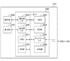
図2において、サーバ101は、制御部200、操作部209、及び表示部210を備え、制御部200は操作部209及び表示部210とそれぞれ接続されている。制御部200は、CPU201、RAM202、ROM203、HDD204、操作部I/F205、表示部I/F206、ネットワークI/F207、及び計時部208を備える。CPU201、RAM202、ROM203、HDD204、操作部I/F205、表示部I/F206、ネットワークI/F207、及び計時部208の各構成要素はシステムバス211を介して互いに接続されている。
2, the
制御部200はサーバ101を統括的に制御する。CPU201はROM203やHDD204に格納されたプログラムを実行して後述する図4のソフトウェアモジュール400の各処理を実行する。これにより、CPU201はシステムバス211に接続された各構成要素を制御する。RAM202はCPU201の作業領域として用いられ、また、RAM202は各データの一時格納領域として用いられる。ROM203は各データやプログラム等を格納する。HDD204はプログラムや、MFP102〜104の各設定データ及び各設定データの更新日時情報等を含む後述する図5のマスターデータ500を格納する。操作部I/F205は操作部209とデータ通信を行い、表示部I/F206は表示部210とデータ通信を行う。ネットワークI/F207はネットワーク105に接続されたMFP102〜104とデータ通信を行う。計時部208は後述するマスターデータ500に含まれる各設定データが更新された時刻等を計時する。操作部209は、例えば、キーボードであり、ユーザのキーボードの操作によって入力された入力情報を受け付ける。表示部210は各画像を表示する。
The
次に、MFP102〜104のハードウェアの構成について説明する。なお、本実施の形態では、MFP102〜104は同様の構成を有するため、以下、一例として、MFP102を用いて説明する。
Next, the hardware configuration of the
図3は、図1におけるMFP102のハードウェアの構成を概略的に示すブロック図である。
FIG. 3 is a block diagram schematically showing a hardware configuration of the
図3において、MFP102は、制御部300、操作部310、スキャナ311、及びプリンタ312を備え、制御部300は操作部310、スキャナ311、及びプリンタ312とそれぞれ接続されている。制御部300は、CPU301、RAM302、ROM303、HDD304、画像処理部305、操作部I/F306、デバイスI/F307、ネットワークI/F308、及び計時部309を備える。CPU301、RAM302、ROM303、HDD304、画像処理部305、操作部I/F306、デバイスI/F307、ネットワークI/F308、及び計時部309の各構成要素はシステムバス313を介して互いに接続されている。
In FIG. 3, the MFP 102 includes a
制御部300はMFP102を統括的に制御する。CPU301はROM303やHDD304に格納されたプログラムを実行して後述する図6のソフトウェアモジュール600の各処理を実行する。これにより、CPU301はシステムバス313に接続された各構成要素を制御する。RAM302はCPU301の作業領域として用いられ、また、RAM302は各データの一時格納領域として用いられる。ROM303は各データやプログラム等を格納する。HDD304はプログラムや、MFP102の各設定データを含む後述する設定データDBを格納する。また、HDD304はMFP102がサーバ101のバックアップ先に設定された場合、該サーバ101から送信された後述するマスターデータ500を格納する。画像処理部305は、スキャナ311で生成された画像データに対し、画像回転、画像圧縮、解像度変換、色空間変換、階調変換等の画像処理を施す。操作部I/F306は操作部310とデータ通信を行い、デバイスI/F307はスキャナ311及びプリンタ312の各々とデータ通信を行う。ネットワークI/F308はネットワーク105で接続されたサーバ101とデータ通信を行う。計時部309は設定データDBに含まれる設定データが変更された時刻等を計時する。操作部310は図示しない操作キーを含み、ユーザの操作キーの操作によって入力された入力情報を受け付ける。スキャナ311は図示しない原稿台に配置された原稿を読み取って画像データを生成する。プリンタ312はスキャナ311等で生成された画像データに基づいて印刷を行う。
The
図4は、図1のサーバ101のソフトウェアモジュール400の構成を概略的に示すブロック図である。
FIG. 4 is a block diagram schematically showing the configuration of the
図4において、ソフトウェアモジュール400は、設定データ管理モジュール401、通信制御モジュール402、及びバックアップ管理モジュール403を備える。ソフトウェアモジュール400の各処理は、サーバ101のCPU201がROM203やHDD204に格納されたプログラムを実行することによって行われる。
4, the
設定データ管理モジュール401は、管理対象装置の各設定データ及び各設定データの更新日時情報を含む図5のマスターデータ500を管理し、管理対象装置の各設定データ及び各設定データの更新日時情報の更新を行う。マスターデータ500は、登録デバイス管理DB501、デバイス情報DB502、ユーザ情報DB503、及びユーザ設定データDB504を備える。登録デバイス管理DB501は管理対象装置を特定する識別子を含むデータベースである。デバイス情報DB502は各管理対象装置の機器情報や、サーバ時刻及び各管理対象装置が計時した時刻との差を示す補正時間等を管理するデータベースである。本実施の形態では、例えば、サーバ101がMFP102から管理対象装置の登録要求通知を受信した場合、受信された登録要求通知に含まれるMFP102が計時した時刻を取得する。また、サーバ101は、MFP102を管理対象装置として登録する際、取得された時刻を用いてサーバ時刻及びMFP102が計時した時刻との差を算出し、算出された差をデバイス情報DB502の補正時間として設定する。これにより、サーバ101は各管理対象装置の補正時間を管理する。デバイス情報DB502は下記表1に示すように管理対象装置毎に管理される。
The setting

ユーザ情報DB503は管理対象装置を利用するユーザのユーザ情報を管理するためのデータベースであり、例えば、下記表2に示すように、管理対象装置を利用するユーザのユーザID及びユーザ名等を含む。
The
ユーザ設定データDB504は、ユーザ毎に設定された管理対象装置の設定データを管理するためのデータベースである。ユーザ設定データDB504は、例えば、下記表3に示すように、各設定データを識別するための識別子や各設定データの更新日時情報を含む。
The user setting
通信制御モジュール402は、管理対象装置の設定データの同期を行うための各通信の制御を行う。バックアップ管理モジュール403は設定されたバックアップ先にマスターデータ500を送信するための各通信を制御する。
The
図6は、図1のMFP103のソフトウェアモジュール600の構成を概略的に示すブロック図である。
FIG. 6 is a block diagram schematically showing the configuration of the
図6において、ソフトウェアモジュール600は、設定データ管理モジュール601及び通信制御モジュール602を備える。ソフトウェアモジュール600の各処理は、MFP102のCPU301がROM303やHDD304に格納されたプログラムを実行することによって行われる。
In FIG. 6, the
設定データ管理モジュール601はMFP102の設定データに関する情報を含む下記表4の設定データDBを管理する。
A setting
通信制御モジュール602はHDD304に格納された設定データの同期を行うための各通信の制御を行う。例えば、通信制御モジュール602は、更新された設定データの取得を要求する差分取得要求通知を定期的に行う。差分取得要求通知は、例えば、MFP103の電源管理状態やジョブの実行状態に基づいて送信される。
The
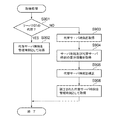
図7は、図1のMFP103で実行される差分取得要求通知の送信処理の手順を示すフローチャートである。
FIG. 7 is a flowchart showing a procedure of a difference acquisition request notification transmission process executed by the
図7の処理は、CPU301がROM303やHDD304に格納されたプログラムを実行することによって行われる。
The processing in FIG. 7 is performed by the
図7において、まず、CPU301は予め設定された差分取得要求通知の送信タイミングの条件を満たしたか否かを判別する(ステップS701)。差分取得要求通知は所定の日時以降に更新された設定データの取得を要求する通知である。差分取得要求通知の送信タイミングの条件を満たすと(ステップS701でYES)、CPU301は差分取得要求通知をサーバ101にリクエスト通知として送信する(ステップS702)。なお、本実施の形態では、差分取得要求通知だけでなく、後述する登録要求通知、全データ取得要求通知、更新要求通知又はデバイス登録要求通知等もリクエスト通知として送信されることもある。したがって、後述するようにリクエスト通知の内容も判別される。また、リクエスト通知としての差分取得要求通知は所定の日時として、例えば、サーバ101から設定データを取得した日時を示す情報を含む。次いで、CPU301はリクエスト通知に対する応答通知をサーバ101から取得すると(ステップS703でYES)、本処理を終了する。
In FIG. 7, first, the
ところで、本実施の形態では、バックアップ先に設定された管理対象装置、例えば、MFP102がサーバ機能を有する場合、管理システム100のサーバ権限をサーバ101からMFP102に移行する場合がある。この場合、サーバ101はマスターデータ500及びバックアップ管理モジュール403を実行するプログラムを代替管理装置としてのMFP102(以下、「代替サーバ」という。)に送信する。代替サーバはサーバ101から各データを受信し、管理システム100のサーバ権限が移行されると、サーバ101と同様に、管理対象装置として登録されたMFP103,104の各設定データを管理する。例えば、MFP103が設定データの更新要求通知を代替サーバに送信した場合、該当する設定データを更新し、当該設定データを更新した日時を設定データの更新日時情報として記録する。このときの設定データの更新日時情報としては設定データが更新された際にMFP102の計時部309が計時した代替サーバ時刻が記録される。すなわち、サーバ権限が代替サーバに移行された後は設定データの更新日時情報が代替サーバ時刻を用いて管理される。
By the way, in this embodiment, when the management target device set as the backup destination, for example, the
次に、代替サーバが管理対象装置から送信されたリクエスト要求の応答を行う処理について説明する。 Next, processing in which the alternative server responds to a request request transmitted from the management target device will be described.
図8A及び図8Bは、図1の代替管理装置としてのMFP102で実行されるリクエスト応答処理の手順を示すフローチャートである。
8A and 8B are flowcharts showing a procedure of request response processing executed by the
図8A及び図8Bの処理は、CPU301がROM303やHDD304に格納されたプログラムを実行することによって行われる。
The processing in FIGS. 8A and 8B is performed by the
ここで、サーバ101から代替サーバにサーバ権限が移行され、代替サーバ時刻がサーバ時刻と一致しない場合、設定データの同期において不具合が生じる可能性がある。例えば、代替サーバ時刻がサーバ時刻よりも3時間遅れている場合を想定する。この場合、サーバ時刻の午前11時にMFP103が設定データの更新要求通知を代替サーバに送信すると、代替サーバは送信された更新要求通知に対応する設定データを更新する際、代替サーバ時刻を用いて午前8時を設定データの更新日時情報として記録する。すなわち、代替サーバはサーバ時刻の午前11時に更新された設定データの更新日時情報として午前8時を記録する。その後、MFP104がサーバ時刻の午前10時以降に更新された設定データの取得を代替サーバに要求しても、代替サーバは、サーバ時刻の午前11時に更新された設定データの更新日時情報が午前8時であると認識してしまう。したがって、代替サーバはサーバ時刻の午前11時に更新された設定データをMFP104に送信しないという不具合が生じる。
Here, if the server authority is transferred from the
これに対応して、本実施の形態では、代替サーバは、サーバ時刻及び代替サーバ時刻の差を管理し、該管理された差を用いて代替サーバ時刻を補正し、補正された代替サーバ時刻に基づいて設定データを管理する。具体的に、代替サーバは、補正された代替サーバ時刻を、ユーザ設定データDB504の各設定データの更新日時情報として用いる。
Correspondingly, in the present embodiment, the alternative server manages the difference between the server time and the alternative server time, corrects the alternative server time using the managed difference, and sets the corrected alternative server time. Manage configuration data based on it. Specifically, the alternative server uses the corrected alternative server time as update date information of each setting data in the user setting
図8A及び図8Bにおいて、まず、CPU301は管理対象装置からリクエスト通知を受信すると(ステップS801でYES)、該リクエスト通知を解析する(ステップS802)。次いで、CPU301はリクエスト通知が新たな設定データの登録を要求する登録要求通知であるか否かを判別する(ステップS803)。
8A and 8B, first, when the
ステップS803の判別の結果、リクエスト通知が登録要求通知であるとき、CPU301はリクエスト通知に基づいて新たに登録を要求された設定データを特定する(ステップS804)。次いで、CPU301は特定された設定データがユーザ設定データDB504に含まれているか否かを判別する(ステップS805)。
As a result of the determination in step S803, when the request notification is a registration request notification, the
ステップS805の判別の結果、特定された設定データがユーザ設定データDB504に含まれているとき、CPU301は後述するステップS808の処理を行う。一方、ステップS805の判別の結果、特定された設定データがユーザ設定データDB504に含まれていないとき、CPU301は特定された設定データをユーザ設定データDB504に登録する(ステップS806)。次いで、CPU301は後述する図9の取得処理を行って、ユーザ設定データDB504を管理するための時刻(以下、「管理時刻」という。)を取得する(ステップS807)。その後、CPU301は取得された管理時刻をユーザ設定データDB504に新たに登録された設定データの更新日時情報として記録する。次いで、CPU301はリクエスト通知に含まれる全ての設定データを特定し終えたか否かを判別する(ステップS808)。
As a result of the determination in step S805, when the specified setting data is included in the user setting
ステップS808の判別の結果、全ての設定データを特定し終えていないとき、CPU301はステップS804の処理に戻る。一方、ステップS808の判別の結果、全ての設定データを特定し終えたとき、CPU301はリクエスト通知の送信元に管理時刻を含む応答通知を送信し(ステップS809)、本処理を終了する。
As a result of the determination in step S808, when all the setting data has not been specified, the
ステップS803の判別の結果、リクエスト通知が登録要求通知でないとき、CPU301はリクエスト通知がユーザ設定データDB504に登録された全ての設定データの取得を要求する全データ取得要求通知であるか否かを判別する(ステップS810)。ステップS810の判別の結果、リクエスト通知が全データ取得要求通知であるとき、CPU301はユーザ設定データDB504の全ての設定データを取得し(ステップS811)、後述する図9の取得処理を行い、管理時刻を取得する(ステップS812)。その後、CPU301は取得された管理時刻及び全ての設定データを含む応答通知を生成し、ステップS809以降の処理を行う。
As a result of the determination in step S803, when the request notification is not a registration request notification, the
ステップS810の判別の結果、リクエスト通知が全データ取得要求通知でないとき、CPU301はリクエスト通知がユーザ設定データDB504に登録された設定データの更新を要求する更新要求通知であるか否かを判別する(ステップS813)。ステップS813の判別の結果、リクエスト通知が更新要求通知であるとき、CPU301はリクエスト通知から更新を要求された設定データを特定する(ステップS814)。次いで、CPU301は特定された設定データがユーザ設定データDB504に更新された後に変更された設定データであるか否かを判別する(ステップS815)。具体的には、特定された設定データが変更された時期がユーザ設定データDB504の直近の更新時期よりも後か否かを判別する。
As a result of the determination in step S810, when the request notification is not the all data acquisition request notification, the
ステップS815の判別の結果、特定された設定データが変更された時期がユーザ設定データDB504の直近の更新時期以前のとき、CPU301は後述するステップS818の処理を行う。一方、ステップS815の判別の結果、特定された設定データが変更された時期がユーザ設定データDB504の直近の更新時期よりも後であるとき、CPU301は変更された設定データを用いて特定された設定データを更新する(ステップS816)。次いで、CPU301は後述する図9の取得処理を行い、管理時刻を取得し(ステップS817)、取得された管理時刻を、ユーザ設定データDB504における更新された設定データの更新日時情報として記録する。次いで、CPU301はリクエスト通知に含まれる全ての設定データを特定し終えたか否かを判別する(ステップS818)。
As a result of the determination in step S815, when the specified setting data is changed before the latest update time of the user setting
ステップS818の判別の結果、全ての設定データを特定し終えていないとき、CPU301はステップS814の処理に戻る。一方、ステップS818の判別の結果、全ての設定データを特定し終えたとき、CPU301はステップS809以降の処理を行う。
As a result of the determination in step S818, when all the setting data has not been specified, the
ステップS813の判別の結果、リクエスト通知が更新要求通知でないとき、CPU301はリクエスト通知が差分取得要求通知であるか否かを判別する(ステップS819)。
If it is determined in step S813 that the request notification is not an update request notification, the
ステップS819の判別の結果、リクエスト通知が差分取得要求通知であるとき、CPU301は差分取得要求通知に対応する設定データをユーザ設定データDB504から取得する(ステップS820)。具体的には、差分取得要求通知が含む所定の日時と、ユーザ設定データDB504の各設定データの更新日時情報とを比較し、更新日時情報が所定の日時よりも後の各設定データを取得する。次いで、CPU301は後述する図9の取得処理を行い、管理時刻を取得し(ステップS821)、取得された管理時刻及び差分取得要求通知に対応する設定データを含む応答通知を生成し、ステップS809以降の処理を行う。これにより、設定データの同期が行われる。
As a result of the determination in step S819, when the request notification is a difference acquisition request notification, the
ステップS819の判別の結果、リクエスト通知が差分取得要求通知でないとき、CPU301はリクエスト通知が管理対象装置の登録を要求するデバイス登録要求通知であるか否かを判別する(ステップS822)。ステップS822の判別の結果、リクエスト通知がデバイス登録要求通知であるとき、CPU301は当該デバイス登録要求通知に基づいて新たな管理対象装置の登録情報を登録し(ステップS823)、ステップS809以降の処理を行う。一方、ステップS822の判別の結果、リクエスト通知がデバイス登録要求通知でないとき、CPU301はリクエスト通知が管理対象装置の登録情報の更新を要求するデバイス情報更新要求通知であるか否かを判別する(ステップS824)。
As a result of the determination in step S819, when the request notification is not a difference acquisition request notification, the
ステップS824の判別の結果、リクエスト通知がデバイス情報更新要求通知であるとき、CPU301は当該デバイス情報更新要求通知に基づいて管理対象装置の登録情報を更新し(ステップS825)、ステップS809以降の処理を行う。一方、リクエスト通知がデバイス情報更新要求通知でないとき、CPU301はリクエスト通知が代替サーバで管理する他のデータに関する要求通知であるか否かを判別する(ステップS826)。
As a result of the determination in step S824, when the request notification is a device information update request notification, the
ステップS826の判別の結果、リクエスト通知が他のデータに関する要求通知であるとき、CPU301は当該他のデータに関する要求通知に基づいて処理を行い(ステップS827)、ステップS809以降の処理を行う。一方、リクエスト通知が他のデータに関する要求通知でないとき、CPU301はエラーを含む応答通知を生成し(ステップS828)、ステップS809以降の処理を行う。
As a result of the determination in step S826, when the request notification is a request notification related to other data, the
図9は、図1の代替管理装置としてのMFP102で実行される取得処理の手順を示すフローチャートである。
FIG. 9 is a flowchart illustrating a procedure of acquisition processing executed by the
図9の処理は、CPU301がROM303やHDD304に格納されたプログラムを実行することによって行われる。
The process of FIG. 9 is performed by the
図9において、まず、CPU301はMFP102自身がサーバ101の代替であるか否かを判別する(ステップS901)。
In FIG. 9, first, the
ステップS901の判別の結果、MFP102自身がサーバ101の代替でないとき、CPU301は計時部309で計時された代替サーバ時刻を管理時刻として取得し(ステップS902)、本処理を終了する。一方、ステップS901の判別の結果、MFP102自身がサーバ101の代替であるとき、CPU301は計時部309で計時された時刻を取得する(ステップS903)。次いで、CPU301はサーバ時刻及び代替サーバ時刻の差分情報を取得する(ステップS904)。具体的に、CPU301は、MFP102のデバイス情報DB502に含まれる予め算出された補正時間を取得する。補正時間はMFP102が管理対象装置として登録されたときに算出されたサーバ時刻及びMFP102の計時部309で計時された時刻の差分である。次いで、CPU301は取得された補正時間を用いて代替サーバ時刻を補正し(ステップS905)、補正された代替サーバ時刻を管理時刻として取得し(ステップS906)、本処理を終了する。ここで、補正時間を用いて補正された代替サーバ時刻は、代替サーバ時刻をサーバ時刻及び代替サーバ時刻の差分情報で補正した時刻であり、サーバ時刻に他ならない。すなわち、図9の処理では、MFP102自身がサーバ101の代替であるとき、管理時刻として代替サーバ時刻ではなく、サーバ時刻が実施的に取得される。そして、管理時刻は更新日時情報としてユーザ設定データDB504に記録される。したがって、MFP102自身がサーバ101の代替となったとしても、ユーザ設定データDB504の各設定データの更新日時情報は実質的にサーバ時刻で管理される。
As a result of the determination in step S901, when the
上述した図8A、図8B、及び図9の処理によれば、MFP102自身がサーバ101の代替となったとしても、ユーザ設定データDB504の各設定データの更新日時情報は実質的にサーバ時刻で管理される。これにより、差分取得要求通知に対し、代替サーバ時刻では無く、サーバ時刻と差分取得要求通知が含む所定の日時とが比較されることになる。すなわち、差分取得要求通知に対する応答通知の生成を常にサーバ時刻に基づいて行うことができる。その結果、設定データの同期において不具合が生じるのを防止することができる。
8A, 8B, and 9 described above, even when the
上述した実施の形態では、サーバ101のバックアップ先に設定された管理対象装置を代替管理装置とした場合について説明したが、代替管理装置は管理対象装置に限られない。例えば、図2のハードウェアと同様の構成を有し、且つ図4のソフトウェアモジュール400を備える他のサーバ装置であってもよい。
In the above-described embodiment, the case has been described where the management target device set as the backup destination of the
また、上述した実施の形態では、他のサーバ装置が代替管理装置である場合、代替管理装置がサーバ101からマスターデータ500を受信する際にサーバ時刻を含む通知を取得してもよい。これにより、サーバ101からサーバ時刻を取得するためだけにサーバ101とデータ通信を行う必要をなくすことができる。その結果、サーバ時刻の取得処理に起因する代替サーバの通信負荷が増えるのを抑制することができる。
In the above-described embodiment, when the other server device is an alternative management device, when the alternative management device receives the
さらに、上述した実施の形態では、取得された通知に含まれるサーバ時刻を用いてサーバ時刻及び代替サーバ時刻の差を算出してもよい。これにより、サーバ時刻を確実に取得することができ、もって、代替サーバ時刻を確実に補正することができる。 Furthermore, in the above-described embodiment, the difference between the server time and the alternative server time may be calculated using the server time included in the acquired notification. As a result, the server time can be acquired with certainty, and the alternative server time can be reliably corrected.
本発明は、上述の実施の形態の1以上の機能を実現するプログラムをネットワーク又は記憶媒体を介してシステム又は装置に供給し、該システム又は装置のコンピュータにおける1つ以上のプロセッサがプログラムを読み出して実行する処理でも実現可能である。また、本発明は、1以上の機能を実現する回路(例えば、ASIC)によっても実現可能である。 The present invention supplies a program that realizes one or more functions of the above-described embodiments to a system or apparatus via a network or a storage medium, and one or more processors in a computer of the system or apparatus read the program. It can also be realized by processing to be executed. The present invention can also be realized by a circuit (for example, ASIC) that realizes one or more functions.
101 サーバ
102 MFP
301 CPU
301 CPU
Claims (12)
前記管理装置が計時する第1の時刻及び前記代替管理装置が計時する第2の時刻の差を用いて前記第2の時刻を補正する補正手段と、
前記補正された第2の時刻に基づいて前記設定データを管理する管理手段とを備えることを特徴とする管理システム。 A management system including an alternative management device that performs alternative management of setting data managed by a management device,
Correction means for correcting the second time using a difference between a first time measured by the management device and a second time measured by the alternative management device;
A management system comprising: management means for managing the setting data based on the corrected second time.
前記代替管理装置が前記管理対象装置として登録されたときに前記第1の時刻及び前記第2の時刻の差が算出されることを特徴とする請求項1記載の管理システム。 The management device registers the replacement management device as a management target device,
The management system according to claim 1, wherein a difference between the first time and the second time is calculated when the alternative management device is registered as the management target device.
前記管理装置が計時する第1の時刻及び前記代替管理装置が計時する第2の時刻の差を用いて前記第2の時刻を補正する補正手段と、
前記補正された第2の時刻に基づいて前記設定データを管理する管理手段とを備えることを特徴とする代替管理装置。 An alternative management device that performs alternative management of setting data managed by the management device,
Correction means for correcting the second time using a difference between a first time measured by the management device and a second time measured by the alternative management device;
An alternative management apparatus comprising: management means for managing the setting data based on the corrected second time.
前記代替管理装置が前記管理対象装置として登録されたときに前記第1の時刻及び前記第2の時刻の差が算出されることを特徴とする請求項6記載の代替管理装置。 Registered as a management target device from the management device,
The alternative management apparatus according to claim 6, wherein a difference between the first time and the second time is calculated when the alternative management apparatus is registered as the management target apparatus.
前記管理装置が計時する第1の時刻及び前記代替管理装置が計時する第2の時刻の差を用いて前記第2の時刻を補正する補正ステップと、
前記補正された第2の時刻に基づいて前記設定データを管理する管理ステップとを有することを特徴とする管理方法。 A method of managing the setting data executed by an alternative management device that performs alternative management of setting data managed by a management device,
A correction step of correcting the second time using a difference between a first time measured by the management device and a second time measured by the alternative management device;
A management step of managing the setting data based on the corrected second time.
前記管理方法は、
前記管理装置が計時する第1の時刻及び前記代替管理装置が計時する第2の時刻の差を用いて前記第2の時刻を補正する補正ステップと、
前記補正された第2の時刻に基づいて前記設定データを管理する管理ステップとを有することを特徴とするプログラム。 A program that causes a computer to execute the setting data management method executed by an alternative management device that performs alternative management of setting data managed by a management device,
The management method is:
A correction step of correcting the second time using a difference between a first time measured by the management device and a second time measured by the alternative management device;
A management step of managing the setting data based on the corrected second time.
Priority Applications (3)
| Application Number | Priority Date | Filing Date | Title |
|---|---|---|---|
| JP2016037030A JP2017156819A (en) | 2016-02-29 | 2016-02-29 | Management system, substitution management unit, management method, and program |
| US15/439,011 US10037049B2 (en) | 2016-02-29 | 2017-02-22 | Management system that performs processing for synchronizing setting data, alternative management apparatus, management method, and storage medium |
| CN201710114470.4A CN107132999A (en) | 2016-02-29 | 2017-02-28 | Management system, replacement management equipment, management method and storage medium |
Applications Claiming Priority (1)
| Application Number | Priority Date | Filing Date | Title |
|---|---|---|---|
| JP2016037030A JP2017156819A (en) | 2016-02-29 | 2016-02-29 | Management system, substitution management unit, management method, and program |
Publications (1)
| Publication Number | Publication Date |
|---|---|
| JP2017156819A true JP2017156819A (en) | 2017-09-07 |
Family
ID=59678965
Family Applications (1)
| Application Number | Title | Priority Date | Filing Date |
|---|---|---|---|
| JP2016037030A Pending JP2017156819A (en) | 2016-02-29 | 2016-02-29 | Management system, substitution management unit, management method, and program |
Country Status (3)
| Country | Link |
|---|---|
| US (1) | US10037049B2 (en) |
| JP (1) | JP2017156819A (en) |
| CN (1) | CN107132999A (en) |
Families Citing this family (1)
| Publication number | Priority date | Publication date | Assignee | Title |
|---|---|---|---|---|
| CN113198174B (en) * | 2021-06-03 | 2022-07-22 | 腾讯科技(深圳)有限公司 | Time synchronization method and device, electronic equipment and readable storage medium |
Family Cites Families (12)
| Publication number | Priority date | Publication date | Assignee | Title |
|---|---|---|---|---|
| JPH05250281A (en) | 1992-03-05 | 1993-09-28 | Toshiba Corp | Time matching system for lan system |
| JP2003108539A (en) | 2001-10-02 | 2003-04-11 | Hitachi Kokusai Electric Inc | Time synchronizing method between server and client |
| DE102004027503B4 (en) * | 2004-06-04 | 2012-08-16 | Robert Bosch Gmbh | Method for establishing a global time base in a timed communication system and communication system |
| CN1968077A (en) * | 2006-09-19 | 2007-05-23 | 威盛电子股份有限公司 | Method and system for time synchronization between client and server-end |
| JP2008262292A (en) * | 2007-04-10 | 2008-10-30 | Hitachi Ltd | Server, and time synchronization method for local terminal group |
| CN101286059B (en) * | 2008-05-29 | 2010-06-02 | 上海交通大学 | On-line measurement data obtaining, correction and gross error serial compensation process |
| CN101425891B (en) * | 2008-12-09 | 2012-09-12 | 中兴通讯股份有限公司 | Time synchronization method, system and customer terminal |
| JP2011128464A (en) * | 2009-12-18 | 2011-06-30 | Canon Inc | Image forming system |
| WO2013160488A1 (en) * | 2012-04-26 | 2013-10-31 | Nube Print Sl | Remote program control device for copiers and printers |
| CN104601349B (en) * | 2013-10-30 | 2017-12-05 | 北京灵集科技有限公司 | The bearing calibration of network behavior logging time and device |
| CN103607596B (en) * | 2013-11-22 | 2017-11-24 | 北京星网锐捷网络技术有限公司 | Clock alignment processing method and processing device |
| JP6508894B2 (en) * | 2014-07-28 | 2019-05-08 | キヤノン株式会社 | Server apparatus, control method of server apparatus and program |
-
2016
- 2016-02-29 JP JP2016037030A patent/JP2017156819A/en active Pending
-
2017
- 2017-02-22 US US15/439,011 patent/US10037049B2/en not_active Expired - Fee Related
- 2017-02-28 CN CN201710114470.4A patent/CN107132999A/en active Pending
Also Published As
| Publication number | Publication date |
|---|---|
| US10037049B2 (en) | 2018-07-31 |
| CN107132999A (en) | 2017-09-05 |
| US20170248988A1 (en) | 2017-08-31 |
Similar Documents
| Publication | Publication Date | Title |
|---|---|---|
| US9053126B2 (en) | Information processing apparatus, information processing system, and recording medium | |
| US11119710B2 (en) | Server for providing a cloud print service, control method, and storage medium | |
| US9225856B2 (en) | Relay server | |
| KR101958245B1 (en) | Information processing apparatus, information processing system, control method for the information processing apparatus, and program | |
| US9930202B2 (en) | Information processing apparatus ensuring temporal matching with server, method of controlling the information processing apparatus, information processing system, and storage medium | |
| GB2561948A (en) | Information processing apparatus, image forming apparatus, system, method of controlling the same, and storage medium | |
| US9086833B2 (en) | System that outputs status information representing a status of a device | |
| US10282131B2 (en) | Electronic device and application control program both of which are suitable for data backup process and the like | |
| EP3588907B1 (en) | Information processing apparatus, control method for information processing apparatus, and storage medium | |
| JP2017156819A (en) | Management system, substitution management unit, management method, and program | |
| US20100198996A1 (en) | Management device and computer readable medium | |
| WO2017145828A1 (en) | Information processing device for managing data of client device, client device, backup method, and storage medium | |
| JP2017011538A (en) | Image processing device, control method therefor, and program | |
| KR102067860B1 (en) | Server that synchronizes information between information processors, information processing system, information processing apparatus, control method for server, control method for information processing system, control method for information processing apparatus, and computer program | |
| JP2015153117A (en) | document generation system | |
| JP2018045307A (en) | Server device, information processing method and program | |
| JP2015156207A (en) | Information processing system, information processing apparatus, information processing method, and program | |
| JP2012250437A (en) | Management system for image forming apparatus | |
| JP2019095854A (en) | System and apparatus management method | |
| US10645236B2 (en) | Information processing apparatus and control method for synchronizing setting information | |
| JP6819387B2 (en) | Image processing equipment, information processing systems, information processing methods, and programs | |
| JP2014194647A (en) | Information processing device, information processing method, and program | |
| JP2018156359A (en) | Information processing system, information processing method, information processing program, information processing apparatus, and electronic device | |
| JP2016162189A (en) | Information processor, control method thereof and program | |
| JP2010231334A (en) | Electronic device and image forming system |