JP6508317B2 - Gaming machine - Google Patents

Gaming machine Download PDF

Info

Publication number
JP6508317B2
JP6508317B2 JP2017246199A JP2017246199A JP6508317B2 JP 6508317 B2 JP6508317 B2 JP 6508317B2 JP 2017246199 A JP2017246199 A JP 2017246199A JP 2017246199 A JP2017246199 A JP 2017246199A JP 6508317 B2 JP6508317 B2 JP 6508317B2
Authority
JP
Japan
Prior art keywords
display
opening
game
ball
state
Prior art date
Legal status (The legal status is an assumption and is not a legal conclusion. Google has not performed a legal analysis and makes no representation as to the accuracy of the status listed.)
Expired - Fee Related
Application number
JP2017246199A
Other languages
Japanese (ja)
Other versions
JP2018043089A (en
Inventor
岡戸 文宏
文宏 岡戸
裕義 洲崎
裕義 洲崎
佐藤 秀昭
秀昭 佐藤
Current Assignee (The listed assignees may be inaccurate. Google has not performed a legal analysis and makes no representation or warranty as to the accuracy of the list.)
Sanyo Bussan Co Ltd
Original Assignee
Sanyo Bussan Co Ltd
Priority date (The priority date is an assumption and is not a legal conclusion. Google has not performed a legal analysis and makes no representation as to the accuracy of the date listed.)
Filing date
Publication date
Application filed by Sanyo Bussan Co Ltd filed Critical Sanyo Bussan Co Ltd
Priority to JP2017246199A priority Critical patent/JP6508317B2/en
Publication of JP2018043089A publication Critical patent/JP2018043089A/en
Application granted granted Critical
Publication of JP6508317B2 publication Critical patent/JP6508317B2/en
Anticipated expiration legal-status Critical
Expired - Fee Related legal-status Critical Current

Links

Images

Landscapes

  • Pinball Game Machines (AREA)

Description

本発明は、遊技機に関するものである。   The present invention relates to a gaming machine.

例えばパチンコ遊技機等の遊技機においては、表示画面に複数の絵柄を変動表示する絵柄表示装置を備えたものが知られている。かかる遊技機では、例えば遊技領域に設けられた作動口を遊技球が通過したことを契機として、たり状態等の遊技者に有利な特別遊技状態を発生させるか否かのたり抽選が行われると共に絵柄の変動表示が開始される。そしてたり抽選に当選した場合には、表示画面に特定柄組合せ等が最終停止表示されると共に、遊技状態が特別遊技状態に移行する。そして、特別遊技状態への移行に伴い、例えば遊技領域に設けられた1つの可変入球装置の開閉が開始され、技球が払い出されるようになっている。 For example, in a gaming machine such as a pachinko gaming machine, one provided with a pattern display device for variably displaying a plurality of symbols on a display screen is known. In such a gaming machine, for example a hydraulic port provided in the game region triggered by the game ball has passed, whether the person or lottery line to generate a favorable special game state to the player, such as those or state At the same time, the variable display of the pattern is started. And when was elected to the person or lottery, particular along with the picture pattern set together, etc. is finally stopped and displayed on the display screen, the gaming state is shifted to the special game state. Along with the shift to the special game state, for example, opening and closing of one variable ball entrance device provided in the game area is started, so that the Yu technique balls are paid out.

絵柄の変動表示についてより詳しくは、先ず絵柄が変動を開始し、全ての絵柄が停止した際に特柄組合せとなっていれば特別遊技状態に移行するという流れが一般的である。 More details about the pattern of the variation display, first picture starts fluctuation, flow of the pattern of all hand shifts to the special game state if a picture pattern sets suit the particular upon stopped common is there.

また、可変入球装置は、特別遊技状態でない状況において、遊技球が入球できない又は入球し難い閉鎖状態となっており、特別遊技状態に移行すると、規定回数(例えば15回)を上限として遊技球が入球し易い開放状態に切り換えられる。また、各開放状態は、所定時間(例えば29.5秒)が経過するか、遊技球が可変入球装置に所定数(例えば10個)入球するかのいずれかが成立するまで維持されることが一般的である(例えば特許文献1参照)。   In addition, the variable ball entry device is in a closed state where game balls can not enter or hardly enter in the special gaming state, and when transitioning to the special gaming state, the specified number of times (for example, 15 times) is the upper limit The game ball is switched to the open state where it is easy to enter the ball. In addition, each open state is maintained until a predetermined time (for example, 29.5 seconds) elapses or a predetermined number (for example, ten pieces) of gaming balls enter the variable ball entry device. That is common (see, for example, Patent Document 1).

しかしながら、上記構成のパチンコ機においては、遊技が単調化するという問題が懸念される。 However, in the pachinko machine of the above configuration, a problem that Yu technique is monotonized that might start.

特開2005−074175号公報JP 2005-074175 A

本発明は上記例示した事情に鑑みてなされたものであり、遊技が単調化することを抑制し得る遊技機を提供することを目的とするものである。 The present invention has been made in view of the above illustrated situation such, it is an object to provide a gaming machine capable of suppressing the Yu technique is monotonized.

請求項1記載の発明は、
表示部に絵柄を変動表示する絵柄表示装置と、
開放状態と閉鎖状態とに切り換え可能な複数の可変入球装置と、
動条件成立に基づいて、遊技者に有利な特別遊技状態を発生させるか否かの抽選を行う主制御手段と、
当該主制御手段が前記抽選の結果に応じた指令情報を出力した場合に前記絵柄の変動表示を行い、前記抽選の結果が前記特別遊技状態の発生当選である場合には、その変動表示が終了する場合に特定の絵柄組合せが停止表示されるように前記絵柄表示装置を表示制御し、前記抽選の結果が前記特別遊技状態の発生当選でない場合には、その変動表示が終了する場合に前記特定の絵柄組合せ以外の絵柄組合せが停止表示されるように前記絵柄表示装置を表示制御する表示制御手段と
を備え、
前記主制御手段は、
前記抽選の結果が前記特別遊技状態の発生当選であって、前記絵柄の変動表示が終了した場合に、遊技状態を前記特別遊技状態に移行させる特別遊技状態移行手段と、
前記可変入球装置のいずれかに遊技球が入球した場合、遊技者に特典が付与されるようにする特典付与手段と、
前記閉鎖状態から前記開放状態に切り換えるべき可変入球装置を特定するための設定を行う設定手段と、
前記特別遊技状態において、前記設定手段の設定結果に基づいて、対応する可変入球装置を開放状態とした後に閉鎖状態に切り換える開閉制御を行う開閉制御手段と
を備え、
前記特別遊技状態の前記開閉制御のパターンとして、前記設定手段による設定態様が相違する第1のパターンと、第2のパターンとを有しており、
前記表示制御手段は、前記第1のパターンの前記開閉制御となる前記特別遊技状態に移行する場合と、前記第2のパターンの前記開閉制御となる前記特別遊技状態に移行する場合とで、前記絵柄の変動表示が終了する場合に同一の前記特定の絵柄組合せが停止表示され得るようにする手段を有し、
当該遊技機は、前記絵柄表示装置とは別個に設けられ、前記表示制御手段を介することなく前記主制御手段によって制御される別表示手段を備え、
当該別表示手段による表示領域は、前記表示部よりも小さく設定されており、
前記絵柄表示装置と前記別表示手段とが離間して配置されており、
前記主制御手段は、前記抽選の結果が前記特別遊技状態の発生当選である場合には、前記別表示手段の表示を変化させた後に特定表示が停止表示されるように前記別表示手段を制御し、前記抽選の結果が前記特別遊技状態の発生当選でない場合には、前記別表示手段の表示を変化させた後に前記特定表示以外の所定表示が停止表示されるように前記別表示手段を制御するものであり、前記第1のパターンの前記開閉制御となる前記特別遊技状態に移行する場合と、前記第2のパターンの前記開閉制御となる前記特別遊技状態に移行する場合とで、前記別表示手段の前記特定表示の停止表示内容を異ならせる手段を有しており、
複数の前記可変入球装置として第1可変入球装置と第2可変入球装置とを有しており、
前記特別遊技状態は、前記第1可変入球装置の前記開閉制御を第1回数実行した後、前記第2可変入球装置の前記開閉制御を第2回数実行し、その後、前記第1可変入球装置の前記開閉制御を実行することなく当該特別遊技状態を終了するように構成されており、
前記第1のパターンと前記第2のパターンとは、前記特別遊技状態における前記第1回数が異なるものであり、
前記設定手段は、前記抽選の結果が前記特別遊技状態の発生当選である場合に、当該発生当選に対応して移行する前記特別遊技状態での前記第1回数を設定する回数設定手段を備え、
前記開閉制御手段は、
前記特別遊技状態において実行された前記第1可変入球装置の前記開閉制御の実行回数が前記回数設定手段により設定された前記第1回数に達しているか否かを判定する判定手段と、
前記判定手段の判定結果に基づいて前記第1可変入球装置の前記開閉制御と前記第2可変入球装置の前記開閉制御との切り替えを行う切替手段と、
を備え、
前記切替手段は、前記実行回数が前記回数設定手段により設定された前記第1回数に達していないと前記判定手段により判定された場合、前記第1可変入球装置の前記開閉制御を実行する一方、前記実行回数が前記回数設定手段により設定された前記第1回数に達していると前記判定手段により判定された場合、前記第2可変入球装置の前記開閉制御を実行するものであることを特徴とする。
The invention according to claim 1 is
A pattern display device that variably displays a pattern on a display unit;
A plurality of variable ball entry devices switchable between an open state and a closed state;
Based on the work movement conditions are satisfied, the main control means for performing whether lottery to generate a favorable special game state to the player,
When the main control means outputs command information according to the result of the lottery, the variable display of the symbol is performed, and when the result of the lottery is the occurrence winning of the special gaming state, the variable display is ended. The display control of the symbol display device is performed so that a specific symbol combination is stopped and displayed, and when the result of the lottery is not the occurrence winning of the special gaming state, the identification is performed when the variation display is ended. And display control means for controlling the display of the pattern display device so that a pattern combination other than the pattern combination is stopped .
The main control means
Special gaming state transition means for transitioning the gaming state to the special gaming state when the result of the lottery is the occurrence winning of the special gaming state and the variation display of the pattern is ended;
A bonus giving means for giving a player a bonus when the game ball enters any of the variable ball entry devices;
Setting means for setting for specifying a variable ball entry device to be switched to the open state from the closed state;
Open / close control means for performing open / close control to switch to the closed state after opening the corresponding variable ball entry device based on the setting result of the setting means in the special gaming state;
Equipped with
As a pattern of the opening and closing control of the special gaming state, it has a first pattern and a second pattern in which setting modes by the setting means are different,
The display control means is switched to the special game state in which the open / close control of the first pattern is performed, and in the case of transition to the special game state in which the open / close control of the second pattern is performed. And means for enabling the same specific pattern combination to be stopped and displayed when the variable display of the pattern ends.
The gaming machine is provided separately from the pattern display device, and includes another display means controlled by the main control means without the display control means.
The display area by the separate display means is set smaller than the display unit,
The pattern display device and the separate display means are disposed apart from each other,
The main control means controls the other display means so that the specific display is stopped and displayed after changing the display of the other display means, when the result of the lottery is the occurrence winning of the special game state. If the result of the lottery is not an occurrence winning of the special gaming state, the control of the other display means is controlled so that the predetermined display other than the specific display is stopped after the display of the other display means is changed. And the above-mentioned separate processing is performed in the case of shifting to the special gaming state in which the opening and closing control of the first pattern is performed and in the case of shifting to the special gaming state in which the opening and closing control of the second pattern is performed. It has means for changing the stop display content of the specific display of the display means,
The plurality of variable ball entering devices include a first variable ball entering device and a second variable ball entering device,
In the special game state, after executing the opening and closing control of the first variable ball entry device a first number of times, the opening and closing control of the second variable ball entry device is performed a second number of times, and then the first variable entry The special gaming state is configured to end without executing the opening and closing control of the ball device,
The first pattern and the second pattern are different in the first number of times in the special game state,
The setting means includes number setting means for setting the first number of times in the special gaming state to be shifted in response to the occurrence winning if the result of the lottery is the occurrence winning of the special gaming state,
The opening / closing control means is
A determination unit that determines whether the number of executions of the opening / closing control of the first variable ball storage device executed in the special gaming state has reached the first number set by the number setting unit;
Switching means for switching between the opening / closing control of the first variable ball entry device and the opening / closing control of the second variable ball entry device based on the determination result of the determination means;
Equipped with
The switching means executes the opening / closing control of the first variable ball entry device, when it is determined by the determining means that the number of executions has not reached the first number set by the number setting means. If it is determined by the determination means that the number of executions has reached the first number of times set by the number of times setting means, the opening and closing control of the second variable ball entry device is executed. It features.

本発明によれば、遊技が単調化することを抑制できる。 According to the present invention, Ru can be suppressed to Yu technique is monotonized.

一実施の形態におけるパチンコ機を示す正面図である。It is a front view showing a pachinko machine in one embodiment. パチンコ機の主要な構成を展開又は分解して示す斜視図である。It is a perspective view which develops or disassembles and shows the main composition of a pachinko machine. パチンコ機を構成する本体枠の前面構成を示す正面図である。It is a front view showing the front composition of the main part frame which constitutes a pachinko machine. 遊技盤の構成を示す正面図である。It is a front view which shows the structure of a game board. 前扉枠の構成を示す背面図である。It is a rear view which shows the structure of a front door frame. パチンコ機の構成を示す背面図である。It is a rear view which shows the structure of a pachinko machine. パチンコ機の背面構成を主要部品毎に分解して示す分解斜視図である。It is an exploded perspective view which disassembles and shows back composition of a pachinko machine for every main part. パチンコ機裏面における第1制御基板ユニット、第2制御基板ユニット及び裏パックユニットの配置を示す模式図である。It is a schematic diagram which shows arrangement | positioning of the 1st control board unit, 2nd control board unit, and back pack unit in a pachinko machine back surface. 本体枠及び遊技盤の構成を示す背面図である。It is a rear view which shows the structure of a main body frame and a game board. 本体枠の背面構成を示す斜視図である。It is a perspective view which shows the back surface structure of a main body frame. 遊技盤の背面構成を示す斜視図である。It is a perspective view showing the back composition of a game board. 軸受け金具の構成を示す斜視図である。It is a perspective view showing composition of a bearing bracket. 第1制御基板ユニットの構成を示す正面図である。It is a front view which shows the structure of a 1st control board unit. 第1制御基板ユニットの構成を示す斜視図である。It is a perspective view which shows the structure of a 1st control board unit. 第1制御基板ユニットの分解斜視図である。It is a disassembled perspective view of a 1st control board unit. 第1制御基板ユニットの背面構成を示す分解斜視図である。It is an exploded perspective view showing the back composition of the 1st control board unit. 第2制御基板ユニットの構成を示す正面図である。It is a front view which shows the structure of a 2nd control board unit. 第2制御基板ユニットの構成を示す斜視図である。It is a perspective view which shows the structure of a 2nd control board unit. 第2制御基板ユニットの分解斜視図である。It is a disassembled perspective view of a 2nd control board unit. 裏パックユニットの構成を示す正面図である。It is a front view which shows the structure of a back pack unit. 裏パックユニットの分解斜視図である。It is an exploded perspective view of a back pack unit. タンクレールの分解斜視図である。It is an exploded perspective view of a tank rail. パチンコ機の電気的構成を示すブロック図である。It is a block diagram which shows the electric constitution of a pachinko machine. 図柄表示装置の表示内容を示す説明図である。It is explanatory drawing which shows the display content of a symbol display apparatus. 遊技制御に用いる各種カウンタの概要を示す説明図である。It is an explanatory view showing an outline of various counters used for game control. 主制御装置によるメイン処理を示すフローチャートである。It is a flowchart which shows the main process by a main control apparatus. 通常処理を示すフローチャートである。It is a flowchart which shows normal processing. 外れ図柄カウンタの更新処理を示すフローチャートである。It is a flowchart which shows the update process of a missing symbol counter. 第1特定ランプ部制御処理を示すフローチャートである。It is a flowchart which shows 1st specific lamp | ramp part control processing. 第1図柄変動開始処理を示すフローチャートである。It is a flow chart which shows the 1st design change start processing. 大当たり状態設定処理を示すフローチャートである。It is a flowchart which shows jackpot state setting processing. 開閉態様カウンタと可変入賞装置の開閉態様との関係を示す図である。It is a figure which shows the relationship between an opening-and-closing aspect counter and the opening-and-closing aspect of a variable winning a prize apparatus. 遊技状態移行処理を示すフローチャートである。It is a flow chart which shows game state transition processing. 大入賞口開閉処理を示すフローチャートである。It is a flow chart which shows big winning a prize opening and closing processing. タイマ割込み処理を示すフローチャートである。It is a flowchart which shows timer interruption processing. 始動入賞処理を示すフローチャートである。It is a flow chart which shows starting winning a prize processing. NMI割込み処理を示すフローチャートである。It is a flowchart which shows NMI interrupt processing. 第1特定ランプ部に表示される色の切替表示と図柄表示装置における図柄の変動表示との相関を示すタイムチャートである。It is a time chart which shows correlation with change display of the color displayed on the 1st specification lamp part, and change display of the pattern in a symbol display device. 払出制御装置によるメイン処理を示すフローチャートである。It is a flow chart which shows main processing by a payment control device. 払出制御処理を示すフローチャートである。It is a flow chart which shows payment control processing. 賞球制御処理を示すフローチャートである。It is a flowchart which shows a prize ball control process. 貸球制御処理を示すフローチャートである。It is a flowchart which shows a rental ball control process. 大当たり表示処理を示すフローチャートである。It is a flow chart which shows jackpot display processing. 大当たり状態下での動作を示すタイミングチャートである。It is a timing chart which shows operation under a big hit state. 第2開放動画を示す図である。It is a figure which shows a 2nd open animation. 第1開放動画を示す図である。It is a figure which shows a 1st open animation.

はじめに、本実施の形態から抽出され得る発明群を手段n(n=1,2,3…)として区分して示し、それらを必要に応じて効果等を示しつつ説明する。なお以下においては、理解の容易のため、本実施の形態において対応する構成を括弧書き等で適宜示すが、この括弧書き等で示した具体的構成に限定されるものではない。   First, the invention group that can be extracted from the present embodiment will be divided and shown as means n (n = 1, 2, 3...), And these will be described while showing effects etc. as necessary. In the following, for ease of understanding, the corresponding configuration in the present embodiment is appropriately described in parentheses or the like, but the present invention is not limited to the specific configuration illustrated in the parentheses or the like.

手段1.表示部に絵柄を変動表示する絵柄表示装置(図柄表示装置41)と、
作動条件成立を検出する作動検出手段(主制御装置271の作動入賞処理機能)と、
前記作動条件成立に基づいて、遊技者に有利な特別遊技状態(大当たり状態)を発生させるか否かの抽選を行う抽選手段(主制御装置271の大当たり判別処理S501)と、
前記抽選手段の抽選結果に基づいて前記絵柄の変動表示を行うと共に、前記抽選手段の抽選結果が前記特別遊技状態当選の場合には、前記絵柄が特定絵柄の組合せで停止するよう前記絵柄表示装置を表示制御する表示制御手段(表示制御装置214)と、
前記抽選手段の抽選結果が前記特別遊技状態当選であって、前記絵柄の変動表示が終了した場合に、遊技状態を前記特別遊技状態に移行させる特別遊技状態移行手段(主制御装置271の大当たり状態開始処理機能S703〜S705)と
を備えた遊技機において、
遊技球飛翔領域に設けられると共に、遊技球が入球し易い開放状態と入球し難い閉鎖状態とに切り換え可能な複数の可変入球装置(第1可変入賞装置32a,第2可変入賞装置32b)と、
可変入球装置のいずれかに遊技球が入球した場合、該可変入球装置に応じて異なる特典を遊技者に付与する特典付与手段(主制御装置271、払出制御装置311)と、
遊技状態が前記特別遊技状態である場合、前記各可変入球装置のうち前記閉鎖状態から前記開放状態に切り換えるべき可変入球装置を設定する設定手段(主制御装置271の開放カウンタ確認処理S803)と、
該設定手段の設定結果に基づいて、対応する可変入球装置を開放状態とした後に閉鎖状態に切り換える開閉制御を行うと共に、前記各可変入球装置の開閉回数の合計が特定の複数回数となるまで前記開閉制御を行う開閉制御手段(主制御装置271の大入賞口開放処理S804,S805及び大入賞口閉鎖処理S810)と
を備えたことを特徴とする遊技機。
Means 1. A pattern display device (pattern display device 41) for variably displaying a pattern on the display unit;
Operation detection means (operation winning processing function of main controller 271) for detecting establishment of operation conditions;
Lottery means (jump determination processing S501 of the main control device 271) for performing lottery of whether or not the special gaming state (big hit state) advantageous to the player is generated based on the establishment of the operation condition;
The symbol display device performs the variable display of the pattern based on the lottery result of the lottery means, and stops the symbol in a combination of specific symbols when the lottery result of the lottery means is the special gaming state winning. Display control means (display control device 214) for controlling display of
Special gaming state transitioning means (a jackpot state of the main control device 271 to shift the gaming state to the special gaming state when the lottery result of the lottery means is the special gaming state winning and the variation display of the symbol is finished In a gaming machine provided with start processing functions S703 to S705),
A plurality of variable ball entry devices (first variable winning device 32a, second variable winning device 32b) provided in the game ball flight area and capable of switching between an open state in which the game ball easily enters the ball and a closed state in which the ball is difficult to enter. )When,
Privilege giving means (main control unit 271, payout control unit 311) for giving the player different benefits depending on the variable ball entry device when the game ball enters the variable ball entry device;
When the gaming state is the special gaming state, setting means for setting the variable ball entry device to be switched from the closed state to the open state among the variable ball entry devices (opening counter confirmation processing S803 of the main control device 271) When,
Based on the setting result of the setting means, the open / close control is performed to switch the corresponding variable ball entry device into the open state and then to the closed state, and the total number of open / close times of each variable ball entry device is a specific number of times A game machine comprising opening / closing control means (big winning opening opening processing S804 and S805 and main winning opening closing processing S810 of the main controller 271) for performing the above opening / closing control.

手段1によれば、遊技状態が特別遊技状態に移行すると、複数設けられた可変入球装置の開閉が特定回数行われる。そして、いずれかの可変入球装置に遊技球が入球した場合、可変入球装置に応じて異なる特典が付与される。かかる構成とすることにより、1回の開閉に基づいて付与される特典を変化させることが可能となる。また、可変入球装置を複数設けることにより、付与する特典を比較的簡単に変化させることが可能となると共に、いずれの可変入球装置が開閉されるかを通じてどのような特典が付与され得るのかを遊技者に教示することが可能となる。故に、可変入球装置の開放が行われる前段階においてはいずれの可変入球装置が開放されるのか、さらに特別遊技状態開始から終了までの間にどれだけの特典が付与されるのかを期待させながら遊技者に遊技を行わせることが可能となり、特別遊技状態下における遊技が単調化することを抑制することが可能となる。加えて、かかる構成においては、各可変入球装置の開閉回数の合計が特定回数となるように開閉制御を行うことからも、特別遊技状態下における遊技が単調化することを抑制することが可能となる。可変入球装置が開閉されるという特別遊技状態下における遊技性を特定回数分担保すると共に、遊技者の望む特典が付与される可変入球装置が特定回数のうち何回開閉されるかに遊技者の関心を向けさせることが可能となるからである。以上の結果、特別遊技状態下における遊技が単調化することを好適に抑制することが可能となる。   According to the means 1, when the gaming state shifts to the special gaming state, the plurality of variable ball entry devices are opened and closed a specific number of times. And when a game ball enters into one of the variable ball entry devices, different benefits are given according to the variable ball entry devices. With this configuration, it is possible to change the benefit given based on one opening and closing. Further, by providing a plurality of variable ball entry devices, it becomes possible to change the benefits to be granted relatively easily, and what kind of benefits can be given through which variable ball entry device is opened and closed Can be taught to the player. Therefore, in the pre-opening stage of the variable ball entry device, it is expected that which variable ball entry device will be opened and how much extra bonus is given from the start to the end of the special game state. However, it becomes possible for the player to play a game, and it is possible to suppress monotonization of the game under the special game state. In addition, in such a configuration, since the opening and closing control is performed so that the total number of opening and closing times of each variable ball entry device becomes a specific number, it is possible to suppress monotonization of the game under the special gaming state It becomes. In addition to securing a certain number of times the game play under the special gaming state that the variable ball-in-place device is opened and closed, and the variable ball-in-place device to which the bonus desired by the player is granted is played It is possible to make the person's As a result of the above, it becomes possible to preferably suppress the monotonization of the game under the special game state.

なお、可変入球装置の「遊技球が入球し難い閉鎖状態」とは、遊技球の入球が困難な状態のみならず遊技球の入球が不可能な状態をも含む。   The "closed state in which the game ball does not easily enter the game" of the variable ball entry device includes not only the state where entry of the game ball is difficult but also the state where entry of the game ball is impossible.

手段2.上記手段1において、前記特別遊技状態移行手段が遊技状態を前記特別遊技状態に移行させる場合、前記開閉制御が前記特定回数行われることを教示する開閉回数教示手段(表示制御装置214)を備えることを特徴とする遊技機。   Means 2. In the above means 1, when the special game state transition means shifts the game state to the special game state, it comprises open / close number teaching means (display control device 214) which teaches that the open / close control is performed the specific number of times. A game machine characterized by

手段2によれば、遊技状態が特別遊技状態に移行する場合、各可変入球装置の開閉される合計回数が教示される。かかる構成とすることにより、各開閉制御に伴って複数の可変入球装置のいずれかが開閉される構成にあって、仮に遊技者の望む特典が付与されない可変入球装置の開閉が初回に行われたとしても、遊技者の望む特典が付与される可変入球装置の開閉が次回以降に行われることを期待させながら遊技を行わせることが可能となり、特別遊技状態下における遊技が単調化することを抑制することが可能となる。   According to the means 2, when the game state shifts to the special game state, the total number of times the variable ball entry device is opened and closed is taught. With this configuration, any one of the plurality of variable ball entry devices is opened and closed according to each opening / closing control, and the variable ball entry device is not temporarily provided with the privilege desired by the player. Even if it is, it is possible to play the game while expecting the opening and closing of the variable ball entry device to which the privilege desired by the player is given to be performed after the next time, and the game under the special gaming state becomes monotonous Can be suppressed.

手段3.上記手段1又は手段2において、前記特別遊技状態移行手段が遊技状態を前記特別遊技状態に移行させる前までに、該特別遊技状態下における前記各可変入球装置の開閉回数を導出し得る開閉態様(開放パターン)を決定する開閉態様決定手段(主制御装置271の大当たり状態設定処理機能S502)を備え、
前記設定手段は、前記開閉態様決定手段の決定した開閉態様に基づいて前記各可変入球装置のいずれかを設定することを特徴とする遊技機。
Means 3. An opening / closing mode in which the special gaming state transition means can derive the number of times of opening / closing of each variable ball entry device under the special gaming state before the special gaming state transition means shifts the gaming state to the special gaming state in the means 1 or 2 (Opening pattern) determining means (the jackpot state setting processing function S502 of the main controller 271) for determining the opening pattern;
A game machine characterized in that the setting means sets one of the variable ball entry devices based on the open / close mode determined by the open / close mode determination means.

手段3によれば、特別遊技状態下における各可変入球装置の開閉回数を導出し得る開閉態様は、特別遊技状態に移行する前までに決定される。かかる構成とすることにより、遊技に関わる処理負荷が増大化することを抑制しつつ、特別遊技状態下における遊技が単調化することを抑制することが可能となる。特別遊技状態下においては、可変入球装置を開閉する処理に加えて例えば可変入球装置に入球した遊技球数を確認する処理や当該処理結果に基づいて特典を付与する処理等を行う必要があり、これらの処理負荷のみで多大なものがあるからである。   According to the means 3, the open / close mode which can derive the open / close times of each variable ball entry device under the special game state is determined before shifting to the special game state. With this configuration, it is possible to suppress monotonization of the game under the special game state while suppressing an increase in the processing load related to the game. In the special gaming state, in addition to the process of opening and closing the variable ball entry device, for example, the process of confirming the number of game balls entered into the variable ball entry device and the process of giving benefits based on the process result, etc. There is a huge amount of these processing loads alone.

手段4.上記手段1又は手段2において、前記開閉制御手段が前記特別遊技状態下で初回の開閉制御を行う前までに、該特別遊技状態下における前記各可変入球装置の開閉回数を導出し得る開閉態様(開放パターン)を決定する開閉態様決定手段(主制御装置271の大当たり状態設定処理機能S502)を備え、
前記設定手段は、前記開閉態様決定手段の決定した開閉態様に基づいて前記各可変入球装置のいずれかを設定することを特徴とする遊技機。
Means 4. In the above means 1 or 2, the open / close mode in which the open / close frequency of each variable ball entry device under the special game state can be derived before the open / close control means performs the first open / close control under the special game state (Opening pattern) determining means (the jackpot state setting processing function S502 of the main controller 271) for determining the opening pattern;
A game machine characterized in that the setting means sets one of the variable ball entry devices based on the open / close mode determined by the open / close mode determination means.

手段4によれば、特別遊技状態下における各可変入球装置の開閉回数を導出し得る開閉態様は、特別遊技状態下で初回の開閉制御が行われる前までに決定される。かかる構成とすることにより、遊技に関わる処理負荷が増大化することを抑制しつつ、特別遊技状態下における遊技が単調化することを抑制することが可能となる。特別遊技状態下においては、可変入球装置を開閉する処理に加えて例えば可変入球装置に入球した遊技球数を確認する処理や当該処理結果に基づいて特典を付与する処理等を行う必要があり、これらの処理負荷のみで多大なものがあるからである。   According to the means 4, the open / close mode which can derive the open / close times of each variable ball entry device under the special game state is determined before the first open / close control is performed under the special game state. With this configuration, it is possible to suppress monotonization of the game under the special game state while suppressing an increase in the processing load related to the game. In the special gaming state, in addition to the process of opening and closing the variable ball entry device, for example, the process of confirming the number of game balls entered into the variable ball entry device and the process of giving benefits based on the process result, etc. There is a huge amount of these processing loads alone.

手段5.上記手段3又は手段4において、前記設定手段は、前記開閉態様より導出される開閉回数分だけ1の可変入球装置を連続して設定した後に他の可変入球装置を設定することを特徴とする遊技機。   Means 5. In the means 3 or the means 4, the setting means is characterized in that one variable ball entry device is continuously set by the number of opening and closing times derived from the opening and closing mode and then another variable ball entry device is set. Gaming machine.

手段5によれば、各可変入球装置は、開閉態様より導出される開閉回数分だけ連続して開閉される。かかる構成とすることにより、遊技に関わる制御負荷が増大化することを抑制しつつ、特別遊技状態下における遊技が単調化することを抑制することが可能となる。   According to the means 5, each variable ball entry device is continuously opened and closed by the number of times of opening and closing derived from the opening and closing mode. With this configuration, it is possible to suppress monotonization of the game under the special game state while suppressing an increase in control load related to the game.

手段6.上記手段3乃至手段5のいずれかにおいて、前記開閉態様決定手段の決定した開閉態様を表示する手段を非具備とすることを特徴とする遊技機。   Means 6. A game machine according to any one of the means 3 to 5, wherein the means for displaying the open / close mode determined by the open / close mode determination means is not provided.

手段6によれば、どのような開閉態様に基づいて開閉制御が行われるのかは表示されない。かかる構成とすることにより、開閉制御が行われる毎にいずれの可変入球装置が開閉されるのかを期待させながら遊技を行わせることが可能となり、特別遊技状態下における遊技が単調化することを抑制することが可能となる。   According to the means 6, it is not displayed based on what opening and closing mode the opening and closing control is performed. With such a configuration, it becomes possible to play a game while expecting which variable ball entry device is opened and closed each time the opening and closing control is performed, and the game under the special gaming state becomes monotonous. It becomes possible to suppress.

手段7.上記手段3乃至手段6のいずれかにおいて、前記開閉態様決定手段は、前記作動条件が成立した場合、抽選により前記開閉態様を決定することを特徴とする遊技機。   Means 7. In any one of the means 3 to 6, the opening / closing mode determining means determines the opening / closing mode by lottery if the operation condition is satisfied.

手段7によれば、各可変入球装置の開閉回数を導出し得る開閉態様は、作動条件が成立した場合に抽選により決定される。かかる構成とすることにより、特別遊技状態下における遊技に関わる処理負荷が増大化することを抑制しつつ、特別遊技状態下における遊技が単調化することを抑制することが可能となる。   According to the means 7, the open / close mode which can derive the open / close frequency of each variable ball entry device is determined by lottery when the operation condition is satisfied. With this configuration, it is possible to suppress monotonization of the game under the special game state while suppressing an increase in the processing load related to the game under the special game state.

手段8.上記手段3乃至手段7のいずれかにおいて、前記表示制御手段は、前記抽選手段の抽選結果が前記特別遊技状態当選の場合、複数種設けられた特定絵柄の組合せのうち、1の特定絵柄の組合せが停止するよう前記絵柄表示装置を表示制御するものであり、前記開閉態様決定手段は、前記絵柄表示装置に表示される特定絵柄の組合せから独立して前記開閉態様を決定することを特徴とする遊技機。   Means 8. In any of the means 3 to the means 7, when the lottery result of the lottery means is the special game state winning, the display control means is a combination of one specific pattern among combinations of a plurality of specific patterns provided. And control the display of the pattern display device so as to stop the movement, and the opening / closing mode determining means determines the opening / closing mode independently from a combination of specific patterns displayed on the pattern display device. Gaming machine.

手段8によれば、開閉態様は、停止する特定絵柄の組合せから独立して決定される。かかる構成とすることにより、いかなる特定絵柄の組合せで終了した場合であっても、どれだけ特典が付与されるのかを期待させながら遊技者に遊技を行わせることが可能となり、特別遊技状態下における遊技が単調化することを抑制することが可能となる。   According to the means 8, the opening and closing aspect is determined independently from the combination of the specific patterns to be stopped. With this configuration, it is possible to allow the player to play the game while expecting how much the benefit will be provided, even when the combination of the specific patterns is completed, which makes it possible to perform the game under the special gaming state. It becomes possible to suppress that the game is monotonous.

手段9.上記手段3乃至手段8のいずれかにおいて、前記各可変入球装置の開閉回数を定めた開閉回数パターン(開放パターン)を予め複数記憶する開閉回数記憶手段(主制御装置271のROM502)を備え、前記開閉態様決定手段は、前記複数の開閉回数パターンから1の開閉回数パターンを前記開閉態様として選択することを特徴とする遊技機。   Means 9. In any one of the means 3 to 8, an opening / closing number storage means (ROM 502 of the main control device 271) for storing a plurality of opening / closing number patterns (opening patterns) defining the opening / closing number of each variable ball entry device in advance is provided. The game machine, wherein the open / close mode determination means selects one open / close frequency pattern from the plurality of open / close frequency patterns as the open / close mode.

手段9によれば、各可変入球装置の開閉回数を定めた開閉回数パターンが予め複数記憶されており、この開閉回数パターンの1つを開閉態様として選択することにより、各可変入球装置の開閉回数が決定される。かかる構成とすることにより、比較的簡単な処理構成で特別遊技状態下における各可変入球装置の開閉回数を決定することが可能となる。なお、可変入球装置を2つ備える構成であれば、一方の可変入球装置の開閉回数を定めた開閉回数パターンを予め複数記憶する構成でもよい。一義的に他の可変入球装置の開閉回数を導出できるからである。   According to the means 9, a plurality of open / close frequency patterns defining the open / close frequency of each variable ball entry device are stored in advance, and one of the open / close frequency patterns is selected as the open / close mode. The number of times of opening and closing is determined. With such a configuration, it is possible to determine the number of times of opening and closing of each variable ball entry device under the special game state with a relatively simple processing configuration. In addition, as long as it is a structure provided with two variable ball entering devices, you may be the structure which memorize | stores multiple opening / closing frequency patterns which defined the frequency | count of opening and closing of one variable ball entering device beforehand. This is because it is possible to uniquely derive the number of opening and closing of other variable ball entry devices.

手段10.上記手段3乃至手段8のいずれかにおいて、前記各開閉制御時に開閉制御されるべき可変入球装置を定めた制御パターン(開放パターン)を予め複数記憶する制御パターン記憶手段(主制御装置271のROM502)を備え、前記開閉態様決定手段は、前記複数の制御パターンから1の制御パターンを前記開閉態様として選択することを特徴とする遊技機。   Means 10. A control pattern storage unit (the ROM 502 of the main control device 271 stores in advance a plurality of control patterns (opening patterns) defining the variable ball entry device to be subjected to the opening and closing control in each of the units 3 to 8 And the opening / closing mode determination unit selects one control pattern from the plurality of control patterns as the opening / closing mode.

手段10によれば、各開閉制御時に開閉制御されるべき可変入球装置を定めた制御パターンが予め複数記憶されており、この制御パターンの1つが開閉態様として選択される。かかる構成とすることにより、比較的簡単な処理構成で特別遊技状態下における各可変入球装置の開閉順序及び開閉回数を決定することが可能となる。なお、可変入球装置を2つ備える構成であれば、一方の可変入球装置の開閉制御タイミングを定めた制御パターンを予め複数記憶する構成でもよい。一義的に他の可変入球装置の開閉制御タイミングを導出できるからである。   According to the means 10, a plurality of control patterns in which variable ball entering devices to be controlled to open and close are defined at the time of each opening and closing control are stored in advance, and one of the control patterns is selected as the opening and closing mode. With this configuration, it is possible to determine the open / close order and the number of open / close times of each variable ball entry device under the special game state with a relatively simple processing configuration. In addition, as long as it is a structure provided with two variable ball entering devices, you may be the structure which stores beforehand two or more control patterns which defined opening-and-closing control timing of one variable ball entering device. This is because the opening / closing control timing of another variable ball entry device can be uniquely derived.

手段11.上記手段9又は手段10において、前記作動条件成立に基づいて、前記特別遊技状態と遊技者の有利度合いが異なる第2特別遊技状態(高確率状態)を発生させるか否かの抽選を行う第2抽選手段(主制御装置271の大当たり図柄設定処理S503)と、
前記抽選手段の抽選結果が前記特別遊技状態当選であり且つ前記第2抽選手段の抽選結果が第2特別遊技状態当選である場合、前記特別遊技状態の終了後に遊技状態を前記第2特別遊技状態に移行させる第2特別遊技状態移行手段(主制御装置271の高確率状態移行処理S710)と
を備え、
前記開閉態様決定手段を、
前記第2抽選手段の抽選結果が第2特別遊技状態当選である場合、遊技者に付与される特典が最も大きい開閉回数パターン又は制御パターンの選択率が、他の開閉回数パターン又は制御パターンの選択率と比して高くなるように、且つ、前記第2抽選手段の抽選結果が第2特別遊技状態非当選である場合、遊技者に付与される特典が最も小さい開閉回数パターン又は制御パターンの選択率が、他の開閉回数パターン又は制御パターンの選択率と比して高くなるように構成したことを特徴とする遊技機。
Means 11. In the above means 9 or 10, based on the establishment of the operation condition, a lottery is performed to determine whether or not to generate a second special gaming state (high probability state) in which the special gaming state and the degree of advantage of the player are different. Lottery means (big hit symbol setting process S503 of the main control device 271),
When the lottery result of the lottery means is the special gaming state winning and the lottery result of the second lottery means is the second special gaming state winning, the gaming state after the end of the special gaming state is the second special gaming state Second special gaming state transition means (high probability state transition processing S710 of the main control device 271) for transitioning to
The opening / closing mode determining means;
When the lottery result of the second lottery means is the second special game state winning, the selection rate of the open / close frequency pattern or control pattern with the largest benefit given to the player is the selection of another open / close frequency pattern or control pattern In order to be higher than the rate, and when the lottery result of the second lottery means is the second special gaming state non-winning, selection of the opening / closing number pattern or control pattern with the smallest benefit given to the player A game machine characterized in that the rate is higher than the selection rate of other opening / closing number patterns or control patterns.

手段11によれば、特別遊技状態の終了後に第2特別遊技状態に移行する場合があり、第2抽選手段の抽選結果が第2特別遊技状態当選である場合、開閉回数パターン又は制御パターンのうち遊技者に付与される特典が最も大きい開閉回数パターン又は制御パターンが高確率で選択され、第2抽選手段の抽選結果が第2特別遊技状態非当選である場合、開閉回数パターン又は制御パターンのうち遊技者に付与される特典が最も小さい開閉回数パターン又は制御パターンが高確率で選択される。かかる構成とすることにより、特別遊技状態下における遊技が単調化することを好適に抑制することが可能となる。第2特別遊技状態当選である場合には、第2特別遊技状態へ移行することに伴う有利さに加えて多くの特典付与を受けることが可能となるため、遊技者の有利度合いを好適に高めることが可能となるからである。   According to the means 11, when the special gaming state is ended, the second special gaming state may be shifted, and when the lottery result of the second lottery means is the second special gaming state winning, among the opening / closing number pattern or the control pattern If the opening / closing frequency pattern or control pattern having the largest benefit given to the player is selected with high probability, and the lottery result of the second lottery means is the second special gaming state non-winning, of the opening / closing frequency pattern or control pattern The opening / closing frequency pattern or control pattern with the smallest benefit given to the player is selected with high probability. With this configuration, it is possible to preferably suppress monotonization of the game under the special game state. In the case of winning the second special gaming state, it is possible to receive many benefits in addition to the advantages associated with the transition to the second special gaming state, suitably enhancing the degree of the player's advantage It is because it becomes possible.

手段12.上記手段1乃至手段11のいずれかにおいて、前記設定手段は、付与される特典の小さな可変入球装置から順に設定していくことを特徴とする遊技機。   Means 12. A gaming machine according to any one of the means 1 to 11, wherein the setting means sequentially sets the small variable ball entry device to which the award is given.

手段12によれば、遊技状態が特別遊技状態に移行すると、付与される特典の小さな可変入球装置から順に開閉される。かかる構成とすることにより、何回目の開閉から特典の最も大きな可変入球装置が開閉されるかを期待させながら特別遊技状態下の遊技を行わせることが可能となる。故に、特別遊技状態における遊技が単調化することを好適に抑制することが可能となる。   According to the means 12, when the gaming state shifts to the special gaming state, the variable ball entry device with the small award given is opened and closed in order. With this configuration, it is possible to play the game under the special gaming state while expecting from what opening and closing the largest variable ball-raising device of the benefit is opened and closed. Therefore, it is possible to preferably suppress monotonization of the game in the special game state.

手段13.上記手段1乃至手段12のいずれかにおいて、前記設定手段が前記各可変入球装置のいずれかを設定する場合に、1の特別遊技状態下で先に設定した可変入球装置以上に遊技者に有利な特典が付与される可変入球装置を次に設定するよう設定可能な可変入球装置を規制する規制手段(主制御装置271の短時間開放カウンタ及び短時間開放カウンタ確認処理S803)を設けたことを特徴とする遊技機。   Means 13. In any one of the above means 1 to 12, when the setting means sets any of the variable ball entry devices, the player can receive more than the variable ball entry device previously set under one special game state. A restriction means (short-time opening counter and short-time opening counter confirmation processing S803 of the main control device 271) is provided which restricts the variable ball-in-place device which can be set to set the variable ball-in-place device A game machine characterized by

手段13によれば、特定回数行われる可変入球装置の開放の中で、先に開放された可変入球装置に基づく特典より、次に開放された可変入球装置に基づく特典が遊技者に不利となることはない。かかる構成とすることにより、何回目の開放から遊技者に最も有利な特典の付与される可変入球装置が開放されるのかを期待させながら各開放下の遊技を行わせることが可能となる。故に、特別遊技状態における遊技が単調化することを好適に抑制することが可能となる。   According to the means 13, according to the opening of the variable ball entry device performed a specific number of times, the bonus based on the variable ball entry device opened next to the player based on the benefit based on the variable ball entry device opened earlier There is no disadvantage. With this configuration, it is possible to play the game under each opening while expecting from what number of times the opening is performed the variable ball receiving device to which the most advantageous bonus is given is released. Therefore, it is possible to preferably suppress monotonization of the game in the special game state.

手段14.上記手段1乃至手段13のいずれかにおいて、前記開閉制御手段が可変入球装置を開放状態に切り換える前に、次に開放状態に切り換えられる可変入球装置を示唆する示唆演出を行うよう前記絵柄表示装置を示唆表示制御する示唆演出手段(表示制御装置214の開放動画表示処理S1606,S1607)を備えることを特徴とする遊技機。   Means 14. In any one of the above means 1 to 13, before the opening / closing control means switches the variable ball entry device to the open state, the symbol display is performed to provide a suggestion effect suggesting the variable ball entry device to be switched to the next open state. A game machine characterized by comprising suggestion effect means (open video display processing S1606 and S1607 of the display control device 214) for suggestive display control of the device.

手段14によれば、各開閉制御前には、いずれの可変入球装置が開放されるのかを示唆する示唆演出が行われる。かかる構成とすることにより、複数の可変入球装置を備える構成にあって、可変入球装置のいずれも開放されていないと遊技者が誤認する等の不具合を抑制することが可能となる。   According to the means 14, before each opening / closing control, a suggestive effect indicating which variable ball entry device is to be released is performed. With such a configuration, it is possible to suppress a problem such as the player's misidentification when there is a plurality of variable ball entry devices and none of the variable ball entry devices are opened.

手段15.上記手段14において、前記示唆演出手段は、前記可変入球装置の全てが閉鎖状態にあって、いずれかの可変入球装置が開放状態に切り換えられる前までに、前記示唆演出を行うよう前記絵柄表示装置を示唆表示制御することを特徴とする遊技機。   Means 15. In the above-mentioned means 14, it is preferable that the indication effect means perform the indication effect before all of the variable ball entry devices are in the closed state and before any of the variable ball entry devices are switched to the open state. A game machine characterized by controlling display of a display device.

手段15によれば、示唆演出は、可変入球装置の全てが閉鎖状態にあって、いずれかの可変入球装置が開放状態に切り換えられる前までに行われる。かかる構成とすることにより、可変入球装置のいずれかが開放されている状況下にあっては特典が付与されることを期待させながら遊技を行わせることが可能となり、可変入球装置の全てが閉鎖されている状況下にあっては、次にいずれの可変入球装置が開放されるのかを期待させながら示唆演出を楽しませることが可能となる。故に、可変入球装置の開放を待つ待機時間となりがちであった可変入球装置の閉鎖されている時間を有効活用することが可能となり、特別遊技状態下の遊技を該特別遊技状態の開始から終了まで楽しませることが可能となる。   According to the means 15, the suggestion effect is performed before all of the variable ball entry devices are in the closed state and before any of the variable ball entry devices are switched to the open state. With such a configuration, it is possible to play a game while expecting to receive benefits when any of the variable ball entry devices are open, all of the variable ball entry devices In the closed situation, it is possible to enjoy the suggested rendering while expecting which variable ball entry device will be opened next. Therefore, it becomes possible to make effective use of the closed time of the variable ball entry device which tends to be the waiting time for waiting for the opening of the variable ball entry device, and the game under the special game state is from the start of the special game state It will be possible to entertain until the end.

手段16.上記手段1乃至手段15のいずれかにおいて、前記開閉制御手段は、前記設定手段の設定結果と対応する可変入球装置を開放状態に切り換える開放制御を行う開放制御手段(主制御装置271の大入賞口開放処理S805)と、該開放制御手段が開放制御を開始してから規定時間(29.5秒)が経過した場合、又は開放制御中の可変入球装置に規定数(10個)の遊技球が入球した場合に、当該可変入球装置を閉鎖状態に切り換える閉鎖制御を行う閉鎖制御手段(主制御装置271の大入賞口閉鎖処理S810)とを備えることを特徴とする遊技機。   Means 16. In any one of the above means 1 to 15, the open / close control means performs open control to switch the variable ball entry device corresponding to the setting result of the setting means to the open state (a big win of the main control 271 Opening processing S 805), and when the specified time (29.5 seconds) has elapsed since the opening control means started the opening control, or a predetermined number (10) of games are played in the variable ball entry device during the opening control And a closing control means (a big winning opening closing process S810 of the main control device 271) for performing closing control for switching the variable ball entering device into a closing state when a ball enters the ball.

手段16によれば、開放された可変入球装置は、規定時間が経過した場合又は規定数の遊技球が入球した場合に閉鎖される。かかる構成においては、いずれの可変入球装置が開放された場合であっても、規定時間の経過又は規定数の遊技球入球を以って閉鎖することが可能となるため、比較的簡単な処理で各可変入球装置を開閉制御することが可能となる。また、いずれの可変入球装置が開放された場合であっても遊技者は規定数の遊技球を入球させるべく遊技を行えばよいため、特別遊技状態下における遊技性を遊技者に比較的容易に理解させることが可能となる。   According to the means 16, the opened variable ball entry device is closed when a prescribed time has elapsed or when a prescribed number of gaming balls have entered. In such a configuration, even when any variable ball entry device is opened, it is possible to close with the passage of a prescribed time or with a prescribed number of gaming ball entry balls, so it is relatively simple. It becomes possible to control opening and closing of each variable ball entry device by processing. In addition, the player can play the game in order to make the specified number of game balls enter even when any variable ball entry device is opened. It can be easily understood.

手段17.上記手段1乃至手段16のいずれかにおいて、前記特典付与手段は、可変入球装置に遊技球が入球した場合、可変入球装置毎に異なる所定数の遊技球を払い出すことを特徴とする遊技機。   Means 17. In any one of the above means 1 to 16, the bonus giving means is characterized in that when the game ball enters the variable ball entry device, a different predetermined number of game balls are paid out for each variable ball entry device. Gaming machine.

手段17によれば、可変入球装置に遊技球が入球した場合、可変入球装置毎に異なる所定数の遊技球が払い出される。かかる遊技機に上記手段1乃至手段12の特徴的構成を適用することにより、特別遊技状態下における遊技が単調化することを好適に抑制することが可能となる。各可変入球装置が何回開閉されるかによって特別遊技状態下で払い出される遊技球数が変化することとなるため、最も多くの遊技球が払い出される可変入球装置が開放されることを期待させながら遊技を行わせることが可能となるからである。   According to the means 17, when the game ball enters the variable ball entry device, a predetermined number of different game balls are paid out for each variable ball entry device. By applying the characteristic configurations of the above means 1 to 12 to such a gaming machine, it becomes possible to preferably suppress the monotonization of the game under the special gaming state. Since the number of gaming balls to be paid out under the special gaming state changes depending on how many times each variable ball entry device is opened and closed, it is expected that the variable ball entry device from which the largest number of gaming balls are paid out is opened. It is because it becomes possible to play a game while making it.

手段18.上記手段1乃至手段17のいずれかにおいて、前記各可変入球装置を、遊技球の落下方向(上下方向)に並ぶように配置したことを特徴とする遊技機。   Means 18. A game machine according to any one of the above means 1 to 17, wherein the variable ball entry devices are arranged in the falling direction (vertical direction) of the game ball.

手段18によれば、各可変入球装置は、遊技球の落下方向に並ぶようにして配置されている。かかる構成においては、例えば遊技球を飛翔させる飛翔強度等を各開閉時に変更せずとも各可変入球装置に遊技球を入球させ得るため、遊技者に特別な操作を強いることなく特別遊技状態下における遊技が単調化することを抑制することが可能となる。   According to the means 18, the variable ball entry devices are arranged in line in the falling direction of the gaming balls. In such a configuration, for example, the game ball can be entered into each variable ball entry device without changing the flight intensity etc. for causing the game ball to fly at each opening and closing, so the special game state is not required to force the player to perform special operations. It is possible to suppress monotonization of the game below.

手段19.上記手段18において、前記各可変入球装置の間に、他の遊技部品(釘等)を非配置としたことを特徴とする遊技機。   Means 19. In the above-mentioned means 18, other gaming parts (nails etc.) are not disposed between the respective variable ball entry devices.

手段19によれば、各可変入球装置の間には他の遊技部品が配置されていない。かかる構成とすることにより、遊技機を設計する設計者が意図した通りの特典を遊技者に付与することが可能となる。仮に各可変入球装置の間に他の遊技部品を配置する構成とした場合、可変入球装置への遊技球の入球し易さを、遊技機を設置する遊技場の管理者等が変化させる可能性があるからである。   According to the means 19, no other game component is arranged between the variable ball entry devices. With this configuration, it is possible to give the player the privilege as intended by the designer designing the gaming machine. If it is assumed that other game components are arranged between each variable ball entry device, the manager of the game arcade where the game machine is installed changes the ease of entering the game ball into the variable ball entry device. There is a possibility of

手段20.上記手段18又は手段19において、遊技者に付与される特典の大きい可変入球装置ほど下方に配置したことを特徴とする遊技機。   Means 20. A game machine characterized in that, in the means 18 or the means 19, a variable ball entry device having a large privilege to be awarded to a player is disposed lower.

手段20によれば、遊技者に付与される特典の大きい可変入球装置ほど下方に配置されている。かかる構成とすることにより、遊技者に付与される特典の大きい可変入球装置ほど遊技球が入球し易い構成とすることが可能となる。   According to the means 20, the larger the variable ball entry device with the larger award given to the player, the lower the position. With this configuration, it is possible to configure the game ball to enter the game more easily as the variable ball entry device has a larger award given to the player.

手段21.表示部に絵柄を変動表示する絵柄表示装置(図柄表示装置41)と、
作動条件成立を検出する作動検出手段(主制御装置271の作動入賞処理機能)と、
前記作動条件成立に基づいて、遊技者に有利な特別遊技状態(大当たり状態)を発生させるか否かの抽選を行う抽選手段(主制御装置271の大当たり判別処理S501)と、
前記抽選手段の抽選結果に基づいて前記絵柄の変動表示を行うと共に、前記抽選手段の抽選結果が前記特別遊技状態当選の場合には、前記絵柄が特定絵柄の組合せで停止するよう前記絵柄表示装置を表示制御する表示制御手段(表示制御装置214)と、
前記抽選手段の抽選結果が前記特別遊技状態当選であって、前記絵柄の変動表示が終了した場合に、遊技状態を前記特別遊技状態に移行させる特別遊技状態移行手段(主制御装置271の大当たり状態開始処理機能S703〜S705)と
を備えた遊技機において、
遊技球飛翔領域に設けられると共に、遊技球が入球し易い開放状態と入球し難い閉鎖状態とに切り換え可能な第1可変入球装置(第1可変入賞装置32a)及び第2可変入球装置(第2可変入賞装置32b)と、
前記第1可変入球装置に遊技球が入球した場合、当該入球に基づいて第1特典(15個の遊技球払出)を遊技者に付与する第1特典付与手段(主制御装置271、払出制御装置311)と、
前記第2可変入球装置に遊技球が入球した場合、当該入球に基づいて前記第1特典より有利度合いの小さい第2特典(3個の遊技球払出)を遊技者に付与する第2特典付与手段(主制御装置271、払出制御装置311)と、
遊技状態が前記特別遊技状態である場合、前記各可変入球装置のうち前記閉鎖状態から前記開放状態に切り換えるべき可変入球装置を設定する設定手段(主制御装置271の開放カウンタ確認処理S803)と、
該設定手段の設定結果に基づいて、対応する可変入球装置を開放状態とした後に閉鎖状態に切り換える開閉制御を行うと共に、前記各可変入球装置の開閉回数の合計が特定の複数回数となるまで前記開閉制御を行う開閉制御手段(主制御装置271の大入賞口開放処理S804,S805及び大入賞口閉鎖処理S810)と
を備えたことを特徴とする遊技機。
Means 21. A pattern display device (pattern display device 41) for variably displaying a pattern on the display unit;
Operation detection means (operation winning processing function of main controller 271) for detecting establishment of operation conditions;
Lottery means (jump determination processing S501 of the main control device 271) for performing lottery of whether or not the special gaming state (big hit state) advantageous to the player is generated based on the establishment of the operation condition;
The symbol display device performs the variable display of the pattern based on the lottery result of the lottery means, and stops the symbol in a combination of specific symbols when the lottery result of the lottery means is the special gaming state winning. Display control means (display control device 214) for controlling display of
Special gaming state transitioning means (a jackpot state of the main control device 271 to shift the gaming state to the special gaming state when the lottery result of the lottery means is the special gaming state winning and the variation display of the symbol is finished In a gaming machine provided with start processing functions S703 to S705),
A first variable ball entry device (first variable winning device 32a) and a second variable ball entry device which are provided in the game ball flight area and can be switched between an open state where the game ball easily enters the ball and a closed state where the ball is difficult to enter. Device (the second variable winning device 32b),
First benefit giving means (main control device 271) for giving a first benefit (15 game ball payouts) to the player based on the ball when the game ball enters the first variable ball storage device A payout control device 311),
When a game ball enters the second variable ball entry device, a second benefit (three game ball payouts) with a smaller degree of advantage than the first benefit is awarded to the player based on the ball entry. Privilege giving means (main controller 271, payout controller 311);
When the gaming state is the special gaming state, setting means for setting the variable ball entry device to be switched from the closed state to the open state among the variable ball entry devices (opening counter confirmation processing S803 of the main control device 271) When,
Based on the setting result of the setting means, the open / close control is performed to switch the corresponding variable ball entry device into the open state and then to the closed state, and the total number of open / close times of each variable ball entry device A game machine comprising opening / closing control means (big winning opening opening processing S804 and S805 and main winning opening closing processing S810 of the main controller 271) for performing the above opening / closing control.

手段21によれば、遊技状態が特別遊技状態に移行すると、複数設けられた可変入球装置の開閉が特定回数行われる。そして、第1可変入球装置に遊技球が入球した場合であれば第1特典が付与され、第2可変入球装置に遊技球が入球した場合であれば第1特典より有利度合いの小さい第2特典が付与される。かかる構成とすることにより、1回の開閉に基づいて付与される特典を変化させることが可能となる。また、可変入球装置を複数設けることにより、付与する特典を比較的簡単に変化させることが可能となると共に、いずれの可変入球装置が開閉されるかを通じてどのような特典が付与され得るのかを遊技者に教示することが可能となる。故に、可変入球装置の開放が行われる前段階においてはいずれの可変入球装置が開放されるのか、さらに特別遊技状態開始から終了までの間にどれだけの特典が付与されるのかを期待させながら遊技者に遊技を行わせることが可能となり、特別遊技状態下における遊技が単調化することを抑制することが可能となる。加えて、かかる構成においては、各可変入球装置の開閉回数の合計が特定回数となるように開閉制御を行うことからも、特別遊技状態下における遊技が単調化することを抑制することが可能となる。可変入球装置が開閉されるという特別遊技状態下における遊技性を特定回数分担保すると共に、第1可変入球装置が特定回数のうち何回開閉されるかに遊技者の関心を向けさせることが可能となるからである。以上の結果、特別遊技状態下における遊技が単調化することを好適に抑制することが可能となる。   According to the means 21, when the gaming state shifts to the special gaming state, the plurality of variable ball entry devices are opened and closed a specific number of times. Then, if the game ball enters the first variable ball entry device, the first benefit is awarded, and if the game ball enters the second variable ball entry device, the first benefit is better than the first benefit. A small second benefit is awarded. With this configuration, it is possible to change the benefit given based on one opening and closing. Further, by providing a plurality of variable ball entry devices, it becomes possible to change the benefits to be granted relatively easily, and what kind of benefits can be given through which variable ball entry device is opened and closed Can be taught to the player. Therefore, in the pre-opening stage of the variable ball entry device, it is expected that which variable ball entry device will be opened and how much extra bonus is given from the start to the end of the special game state. However, it becomes possible for the player to play a game, and it is possible to suppress monotonization of the game under the special game state. In addition, in such a configuration, since the opening and closing control is performed so that the total number of opening and closing times of each variable ball entry device becomes a specific number, it is possible to suppress monotonization of the game under the special gaming state It becomes. In addition to guaranteeing the game play under the special game state that the variable ball entry device is opened and closed for a specific number of times, and directing the player's attention to how many times the first variable ball entry device is opened and closed within a specific number of times Because it is possible. As a result of the above, it becomes possible to preferably suppress the monotonization of the game under the special game state.

なお、可変入球装置の「遊技球が入球し難い閉鎖状態」とは、遊技球の入球が困難な状態のみならず遊技球の入球が不可能な状態をも含む。   The "closed state in which the game ball does not easily enter the game" of the variable ball entry device includes not only the state where entry of the game ball is difficult but also the state where entry of the game ball is impossible.

なお、手段21の特徴的構成に上記手段2乃至手段20に記載の特徴的構成を適用してもよく、かかる場合には相乗的効果が期待できる。   The characteristic configurations described in the above means 2 to means 20 may be applied to the characteristic configuration of the means 21, and in such a case, a synergistic effect can be expected.

以下に、以上の各手段を適用し得る各種遊技機の基本構成を示す。   The basic configurations of various gaming machines to which the above-described means can be applied will be shown below.

弾球遊技機:遊技者が操作する操作手段(遊技球発射ハンドル18)と、その操作手段の操作に基づいて遊技球を弾いて発射する球発射手段(発射モータ229等)と、その発射された遊技球を遊技球飛翔領域に導く球通路(レールユニット50の球案内通路)と、前記遊技球飛翔領域内に配置された各遊技部品(一般入賞口31、可変入賞装置32、作動口33、可変表示ユニット35等)とを備えた遊技機。   Ball-and-ball game machine: operation means (game ball emission handle 18) operated by the player, and ball emission means (emission motor 229 etc.) for firing and releasing the game ball based on the operation of the operation means Ball passage (ball guide passage of the rail unit 50) for guiding the game ball to the game ball flight area and each game component (general winning opening 31, variable winning device 32, operation opening 33 disposed in the game ball flight area) , A variable display unit 35 etc.).

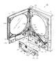
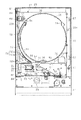
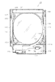
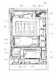
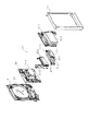
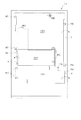
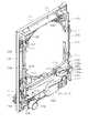
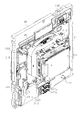
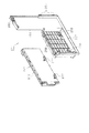
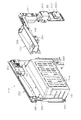
以下、遊技機の一種であるパチンコ遊技機(以下、「パチンコ機」という)の一実施の形態を、図面に基づいて詳細に説明する。図1はパチンコ機10の正面図、図2はパチンコ機10の主要な構成を展開又は分解して示す斜視図、図3はパチンコ機10を構成する本体枠12の前面構成を示す正面図である。なお、図2、図3では便宜上、パチンコ機10の遊技領域内の構成を空白としている。   Hereinafter, an embodiment of a pachinko gaming machine (hereinafter referred to as a "pachinko machine") which is a type of gaming machine will be described in detail based on the drawings. 1 is a front view of a pachinko machine 10, FIG. 2 is a perspective view showing the main configuration of the pachinko machine 10 in an expanded or disassembled state, and FIG. 3 is a front view showing a front configuration of a main frame 12 constituting the pachinko machine 10. is there. In FIG. 2 and FIG. 3, for convenience, the configuration in the game area of the pachinko machine 10 is blank.

図1〜図3に示すように、パチンコ機10は、当該パチンコ機10の外殻を形成する外枠11を備えている。外枠11は、遊技ホールへの設置の際に、いわゆる島設備に取り付けられる。外枠11は、木製の板材を全体として矩形枠状に組み合わせた状態とされ、各板材を小ネジ等の離脱可能な締結部材により固定することによって構成されている。従って、釘やリベットを使って各板材を組み付けていた従来構造と比べて構成部材の再利用(リユース)が容易な構成となっている。本実施の形態では、外枠11の上下方向の外寸は809mm(内寸771mm)、左右方向の外寸は518mm(内寸480mm)となっている。なお、外枠11を合成樹脂やアルミニウム等の金属によって構成してもよい。   As shown in FIGS. 1 to 3, the pachinko machine 10 includes an outer frame 11 that forms an outer shell of the pachinko machine 10. The outer frame 11 is attached to a so-called island facility at the time of installation in the game hall. The outer frame 11 is in a state in which wooden plate members are combined in a rectangular frame shape as a whole, and is configured by fixing each plate member by a detachable fastening member such as a small screw. Therefore, compared with the conventional structure which assembled | attached each board | plate material using a nail | claw or a rivet, it has the structure which is easy to reuse (reuse) of a structural member. In the present embodiment, the outer size of the outer frame 11 in the vertical direction is 809 mm (inner size 771 mm), and the outer size in the left-right direction is 518 mm (inner size 480 mm). The outer frame 11 may be made of a synthetic resin or a metal such as aluminum.

外枠11の一側部には、本体枠12が開閉可能に支持されている。その開閉軸線はパチンコ機10の正面からみて左側に上下へ延びるように設定されており、その開閉軸線を軸心にして本体枠12が前方側に開放できるようになっている。更に言うと、本パチンコ機10には右側に遊技球発射ハンドル18の設置箇所が設けられているため、遊技球発射ハンドル18とは反対側の側部を中心に本体枠12を開閉可能としたということができる。本体枠12は合成樹脂、具体的にはABS樹脂により構成されている。ABS樹脂を用いることにより、比較的低コストで耐衝撃性の高い本体枠12を得ることができる。本体枠12をアルミニウム等の金属によって構成してもよい。なお本実施の形態では、外枠11と本体枠12とにより遊技機本体が構成されている。外枠11に代わる構成として設置枠体を遊技ホール側に予め設けておき、遊技ホールへのパチンコ機10の設置に際しては本体枠12を前記設置枠体に組み付ける構成とすることも可能である。かかる構成では、本体枠12とにより遊技機本体が構成される。   A body frame 12 is supported on one side of the outer frame 11 so as to be openable and closable. The opening / closing axis is set to extend vertically upward to the left as viewed from the front of the pachinko machine 10, so that the body frame 12 can be opened forward with the opening / closing axis as an axis. Furthermore, since the pachinko machine 10 is provided with the game ball launch handle 18 on the right side, the main frame 12 can be opened and closed centering on the side opposite to the game ball launch handle 18 It can be said. The main body frame 12 is made of synthetic resin, specifically, ABS resin. By using the ABS resin, the main frame 12 having high impact resistance can be obtained at relatively low cost. The body frame 12 may be made of a metal such as aluminum. In the present embodiment, the outer frame 11 and the main frame 12 constitute a gaming machine main body. As an alternative to the outer frame 11, an installation frame may be provided in advance on the game hall side, and the main body frame 12 may be assembled to the installation frame when installing the pachinko machine 10 in the game hall. In such a configuration, the gaming machine main body is configured by the main body frame 12.

本体枠12の前面側の下部位置には、前面板14が設けられている。前面板14は横長状に形成され、その横幅は本体枠12の横幅とほぼ一致するように構成されている。前面板14は、幅方向ほぼ中央部において手前側へ膨出した膨出部15aを有するベース部15と、ベース部15の膨出部15a内側に設けられ下方にくぼんだ皿形状をなす球受皿としての下皿16と、下皿16の奥側の壁面を構成する奥壁パネル17とを備えている。ベース部15は本体枠12に対してネジ等の締結部材により固定されていることから、ベース部15が本体枠12に対する取付部を構成している。ベース部15には膨出部15aよりも右方に、手前側へ突出するようにして遊技球発射ハンドル18が設けられている。奥壁パネル17には球排出口17aが設けられており、球排出口17aより排出された遊技球が下皿16内に貯留されるようになっている。   A front plate 14 is provided at a lower position on the front side of the main body frame 12. The front plate 14 is formed in a horizontally long shape, and the width thereof is configured to substantially coincide with the width of the main body frame 12. The front plate 14 has a base portion 15 having a bulging portion 15a bulging toward the near side at a substantially central portion in the width direction, and a bowl-shaped saucer provided inside the bulging portion 15a of the base portion 15 and recessed downward. The lower plate 16 and the back wall panel 17 that constitutes the wall surface on the back side of the lower plate 16 are provided. Since the base portion 15 is fixed to the main body frame 12 by a fastening member such as a screw, the base portion 15 constitutes an attachment portion to the main body frame 12. The game ball emission handle 18 is provided on the base portion 15 so as to project to the front side on the right side of the bulging portion 15a. The back wall panel 17 is provided with a ball discharge port 17a, and gaming balls discharged from the ball discharge port 17a are stored in the lower plate 16.

ベース部15の膨出部15a前面側にはスライド式の球抜きレバー19が設けられている。なお、球抜きレバー19はプッシュ式としてもよい。そして、球抜きレバー19が操作されると下皿16の底面に設けられた図示しない閉鎖板が一体に又はリンクを介して移動して球抜き穴が開放され、下皿16内の貯留球が下方に排出されるよう構成されている。球抜きレバー19には球抜き穴を塞ぐ側へ球抜きレバー19を付勢するコイルバネ等の付勢部材が設けられ、球抜きレバー19の操作が解除された際には付勢部材の付勢力によって閉鎖板が球抜き穴の開放位置に復帰する構成となっている。奥壁パネル17の球排出口17aとは異なる位置には、多数の小孔が集合したスピーカカバー部17bが形成されており、当該パネル17の後方に設置されたスピーカ20の出力音がスピーカカバー部17bを通じて前方に発せられるようになっている。   A slide-type ball removing lever 19 is provided on the front side of the bulging portion 15 a of the base portion 15. The ball release lever 19 may be a push type. When the ball removing lever 19 is operated, a closing plate (not shown) provided on the bottom surface of the lower plate 16 moves integrally or via a link to open the ball removing hole, and the storage balls in the lower plate 16 It is configured to be discharged downward. The ball release lever 19 is provided with a biasing member such as a coil spring which biases the ball release lever 19 to the side for closing the ball removal hole, and when the operation of the ball release lever 19 is released, the biasing force of the biasing member The closure plate is configured to be returned to the open position of the ball removal hole by this. A speaker cover portion 17b in which many small holes are gathered is formed at a position different from the ball discharge port 17a of the back wall panel 17, and the output sound of the speaker 20 installed behind the panel 17 is a speaker cover It is emitted forward through the part 17b.

ベース部15には膨出部15aの左方に灰皿21が設けられている。灰皿21は、内部に溜まった吸い殻等を除去しやすいように手前側下方に反転可能に取り付けられており、その右側面と背面とでベース部15に対面している。具体的な図示は省略するが、灰皿21の右側面には当該灰皿21を回動可能な状態で片持ち支持するための支軸が設けられ、同背面には灰皿21が図示のように上方に開口した位置でベース部15に係止される係止部が設けられている。前面板14はその大部分が本体枠12と同様、ABS樹脂にて成形されている。前面板14はパチンコ機10の前面側に露出されるが、ABS樹脂で成形していることによって、装飾等の目的で表面の適宜箇所にメッキを施すことが可能となる。なお、灰皿21が近くに配置されている関係上、下皿16と奥壁パネル17とを構成する部位に関しては難燃性のABS樹脂を用い、仮に誤ってたばこ等を置いても燃えにくくなるよう構成することが好ましい。   An ashtray 21 is provided on the left side of the bulging portion 15 a in the base portion 15. The ashtray 21 is attached to the front side and lower side so as to be able to easily remove the buttocks and the like accumulated inside, and faces the base portion 15 on the right side surface and the back surface. Although a specific illustration is omitted, on the right side surface of the ashtray 21 is provided a spindle for supporting the ashtray 21 in a rotatable manner in a rotatable manner, and on the back surface, the ashtray 21 is upward as shown. A locking portion is provided which is locked to the base portion 15 at the open position. The front plate 14 is, for the most part, formed of an ABS resin in the same manner as the body frame 12. Although the front plate 14 is exposed on the front side of the pachinko machine 10, by molding it with an ABS resin, it becomes possible to plate an appropriate place on the surface for the purpose of decoration and the like. It should be noted that due to the arrangement of the ashtray 21 nearby, the flame retardant ABS resin is used for the part that constitutes the lower tray 16 and the back wall panel 17, and it becomes difficult to burn even if it is accidentally put cigarettes etc. It is preferable to configure as follows.

本体枠12の前面側の前面板14を除く範囲には、本体枠12を覆うようにして前面扉としての前扉枠13が設けられている。従って、前面板14と前扉枠13とにより本体枠12の前面側全体が覆われている。前扉枠13は、本体枠12に対して開閉可能に取り付けられており、本体枠12と同様、パチンコ機10の正面からみて左側に上下に延びる開閉軸線を軸心にして前方側に開放できるようになっている。なお、前扉枠13は前面板14と同様、ABS樹脂にて成形されている。前扉枠13はパチンコ機10の前面側に露出されるが、ABS樹脂で成形していることによって、装飾等の目的で表面の適宜箇所にメッキを施すことが可能となる。   A front door frame 13 as a front door is provided in a range excluding the front face plate 14 on the front side of the main body frame 12 so as to cover the main body frame 12. Accordingly, the entire front surface side of the main body frame 12 is covered by the front plate 14 and the front door frame 13. The front door frame 13 is attached to the main body frame 12 so as to be openable and closable, and like the main body frame 12, it can be opened forward with an open / close axis extending vertically to the left when viewed from the front of the pachinko machine 10 It is supposed to be. The front door frame 13 is formed of ABS resin as the front plate 14 is. Although the front door frame 13 is exposed on the front side of the pachinko machine 10, by molding it with an ABS resin, it becomes possible to plate an appropriate place on the surface for the purpose of decoration and the like.

前扉枠13の下部位置には、下皿16の上方において手前側へ膨出した膨出部22が設けられ、その膨出部22内側には上方に開口した上皿23が設けられている。上皿23は、後述する払出装置より払い出された遊技球を一旦貯留し、一列に整列させながら遊技球発射装置側へ導くための球受皿である。膨出部22前面側には上皿23用の球抜きレバー24が設けられており、この球抜きレバー24を操作すると上皿23の最下流部付近に設けられた球抜き通路(図示略)が開放され、上皿23内の貯留球が下皿16へ排出されるようになっている。なお、上皿23も下皿16等と同様、難燃性のABS樹脂にて構成することが可能である。   A bulging portion 22 bulging toward the front side above the lower plate 16 is provided at a lower position of the front door frame 13, and an upper plate 23 opening upward is provided inside the bulging portion 22. . The upper tray 23 is a ball tray for temporarily storing game balls paid out from a later described payout device and guiding the game balls to the game ball launcher side while aligning them in a line. A ball release lever 24 for the upper plate 23 is provided on the front side of the bulging portion 22. When the ball release lever 24 is operated, a ball release passage (not shown) provided near the most downstream portion of the upper plate 23 Is released, and the storage balls in the upper plate 23 are discharged to the lower plate 16. The upper plate 23 can also be made of flame-retardant ABS resin, as with the lower plate 16 and the like.

本パチンコ機10では、ガラス扉枠と前飾り枠とを個別に設けこれらを前面枠(本実施の形態の本体枠に相当)に対して各々開閉可能とすると共に前飾り枠に上皿を設けていた従来構成と異なり、ガラス扉枠と前飾り枠とを1つに統合して前扉枠13とし、前扉枠13に対して一体的に上皿23を設ける構成としている。この場合、ガラス扉枠と前飾り枠とを1つに統合して前扉枠13としたため、当該前扉枠13においてガラス支持構造の強度向上が実現できる。つまり、本パチンコ機10では、遊技領域の拡張を目的とし、その遊技領域拡張に伴い大きめのガラス137を前扉枠13に搭載している。従って、ガラス周囲の枠部分が幅狭になり、強度低下の問題が懸念されるが、ガラス下方に上皿一体の枠部分を設けること等によりガラス支持構造の十分な強度が確保できる。なお、ガラス137の縦横寸法は、従来一般に405mm×405mmであったのに対し、本パチンコ機10では453mm×434mmとしている。   In this pachinko machine 10, the glass door frame and the front decoration frame are provided separately, and these can be opened and closed respectively to the front frame (corresponding to the main body frame of the present embodiment) and the upper tray is provided on the front decoration frame. Unlike the conventional configuration, the glass door frame and the front decoration frame are integrated into one to form the front door frame 13, and the upper plate 23 is integrally provided to the front door frame 13. In this case, since the glass door frame and the front decoration frame are integrated into one to form the front door frame 13, strength improvement of the glass support structure can be realized in the front door frame 13. That is, in the pachinko machine 10, with the purpose of expanding the game area, the large glass 137 is mounted on the front door frame 13 along with the expansion of the game area. Accordingly, the frame portion around the glass becomes narrow, and there is a concern about the problem of a reduction in strength. However, by providing a frame portion integral with the upper tray below the glass, sufficient strength of the glass support structure can be secured. The vertical and horizontal dimensions of the glass 137 are generally 45 mm × 405 mm conventionally, but are 453 mm × 434 mm in the present pachinko machine 10.

また、前扉枠13は、少なくともその開閉の際に遊技球発射ハンドル18と干渉しないようにして下方に拡張されている。具体的な数値を示すと、パチンコ機下端から前扉枠13の下端までの寸法Laは、既存の一機種で例えば約201mmであるのに対し、本パチンコ機10では30mm程小さく、約172mmとなっている。また、これに伴いパチンコ機下端から上皿23の上端までの寸法Lbも小さくなっており、既存の一機種では例えば約298mmであるのに対し、本パチンコ機10では約261mmとなっている。ここで、上皿23の位置を下げたことにより、遊技ホールにおいてパチンコ機10左側に並設される球貸し装置のノズル先端との上下方向の距離が大きくなって貸球のこぼれ落ち等が懸念されるが、本実施の形態では、当該ノズルからの貸球排出部分となる左側部分において、膨出部22の壁面を他の壁面より高くした立ち上げ部22aを形成している。これにより、上皿23の位置を下げた構成にあっても貸球のこぼれ落ち等の不都合が解消されるようになっている。立ち上げ部22aの高さ寸法は上皿23の下げ寸法に見合うものであれば良く、その最大高さ寸法は本実施の形態では25mmとされている。   Further, the front door frame 13 is expanded downward so as not to interfere with the game ball emission handle 18 at least when the front door frame 13 is opened or closed. As a specific numerical value, the dimension La from the lower end of the pachinko machine to the lower end of the front door frame 13 is, for example, about 201 mm in one existing model, but is about 30 mm smaller in this pachinko machine 10 and about 172 mm. It has become. Further, along with this, the dimension Lb from the lower end of the pachinko machine to the upper end of the upper plate 23 is also reduced, and for example, about 298 mm in one existing model, it is about 261 mm in the present pachinko machine 10. Here, by lowering the position of the upper plate 23, the vertical distance from the tip end of the ball lending device provided parallel to the left side of the pachinko machine 10 in the game hall becomes large, and there is a concern that the balls will fall off, etc. However, in the present embodiment, the rising portion 22a in which the wall surface of the bulging portion 22 is made higher than the other wall surfaces is formed on the left side portion which is a portion for discharging balls from the nozzle. As a result, even when the upper tray 23 is lowered, inconveniences such as spilled balls can be resolved. The height dimension of the rising portion 22a may be any as long as it corresponds to the lowering dimension of the upper tray 23, and the maximum height dimension thereof is 25 mm in the present embodiment.

なお、前扉枠13においては、上皿形成のための膨出部22が手前側に大きく膨出して設けられるが、上皿23より上方のそれ以外の部位(後述する環状電飾部102等)は、球貸し装置のノズルとの干渉を避けるべく手前側への膨出が制限されている。具体的には、外枠11からの手前側への寸法が45〜50mmに制限されている。   In addition, in the front door frame 13, although the bulging part 22 for upper plate formation is bulgingly provided in the near side greatly, it is provided above other parts of the upper plate 23 (ring electric decoration part 102 etc. which are mentioned later) B) is limited in bulging toward the front side in order to avoid interference with the nozzle of the ball lending device. Specifically, the dimension from the outer frame 11 to the front side is limited to 45 to 50 mm.

図3に示すように、本体枠12は、外形が前記外枠11とほぼ同一形状をなす樹脂ベース25を主体に構成されており、樹脂ベース25の中央部には略円形状の窓孔26が形成されている。樹脂ベース25の後側には遊技盤30が着脱可能に装着されている。図4に示すように、遊技盤30は略四角形状の合板よりなり、その周縁部が樹脂ベース25の裏側に当接した状態で取着されている。すなわち、遊技盤30はパチンコ機10後方より取り付けられ、遊技盤30の前面部の略中央部分だけが樹脂ベース25の窓孔26を通じて本体枠12の前面側に露出した状態となっている。なお、遊技盤30は、従来と同様、上下方向の長さは476mm、左右方向の長さは452mmとなっている。   As shown in FIG. 3, the main body frame 12 is mainly composed of a resin base 25 whose outer shape has substantially the same shape as the outer frame 11, and a substantially circular window hole 26 is formed in the center of the resin base 25. Is formed. The game board 30 is detachably mounted on the rear side of the resin base 25. As shown in FIG. 4, the game board 30 is made of a substantially square plywood, and is attached in a state where its peripheral edge portion abuts on the back side of the resin base 25. That is, the game board 30 is attached from the rear of the pachinko machine 10, and only the substantially central portion of the front face of the game board 30 is exposed to the front side of the main body frame 12 through the window hole 26 of the resin base 25. As in the conventional case, the game board 30 has a length of 476 mm in the vertical direction and a length of 452 mm in the horizontal direction.

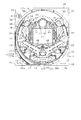
次に、遊技盤30の構成を図4に基づいて説明する。遊技盤30には、ルータ加工が施されることによって前後方向に貫通する大小複数の開口部が形成されている。各開口部には一般入賞口31、第1可変入賞装置32a、第2可変入賞装置32b、作動口33、スルーゲート34及び可変表示ユニット35等がそれぞれ設けられている。実際には、一般入賞口31、各可変入賞装置32a,32b、作動口33、スルーゲート34及び可変表示ユニット35は木ねじ等により遊技盤表面に取り付けられている。本実施の形態では、可変表示ユニット35が遊技盤30の略中央に配置され、その下方に作動口33が配置され、さらにその下方に第1可変入賞装置32aと第2可変入賞装置32bとが配置されている。第1可変入賞装置32aと第2可変入賞装置32bとは、縦並びにすなわち遊技球の落下方向に近接するように配置されている。また、可変表示ユニット35の左右両側にスルーゲート34が配置され、遊技盤30の下部両側に一般入賞口31がそれぞれ複数配置されている。作動口33には、所定の条件下で作動状態(開放状態)となる電動役物が付随的に設けられている。前記一般入賞口31、各可変入賞装置32a,32b及び作動口33に遊技球が入ると、それが後述する検出スイッチにより検出され、その検出結果に基づいて上皿23(場合によっては下皿16)に対し所定数の賞品球が払い出される。具体的には、作動口33及び第2可変入賞装置32bに遊技球が入った場合には3個の賞品球が払い出され、一般入賞口31に遊技球が入った場合には10個の賞品球が払い出され、第1可変入賞装置32aに遊技球が入った場合には15個の賞品球が払い出される。その他に、遊技盤30の最下部にはアウト口36が設けられており、各種入賞口等に入らなかった遊技球はアウト口36を通って図示しない球排出路の方へと案内されるようになっている。アウト口36は、遊技盤30の下端略中央を逆U字状に切り欠いて形成されている。そのため、アウト口を穴状に形成していた従来構成に比べ、アウト口形成が容易となる(但し、図4では手前側にレールユニット50が重ねて設けられているため、アウト口36が閉じた状態で示されている)。また、遊技盤30には、遊技球の落下方向を適宜分散、調整等するために多数の釘が植設されていると共に、風車37等の各種部材(役物)が配設されている。但し、第1可変入賞装置32aと第2可変入賞装置32bとの間には、釘やその他の部材は配置されていない。これは、第2可変入賞装置32bへの遊技球の入球し易さを一定とするための工夫である。すなわち、第1可変入賞装置32aと第2可変入賞装置32bとの間に釘等の部材を配置した場合、本パチンコ機10を設置する遊技場の管理者等が前記部材の位置を調整し、第2可変入賞装置32bへの遊技球の入球し易さを変化させる可能性があるからである。   Next, the configuration of the game board 30 will be described based on FIG. The gaming board 30 is formed with a plurality of large and small openings penetrating in the front-rear direction by being subjected to router processing. Each opening is provided with a general winning opening 31, a first variable winning device 32a, a second variable winning device 32b, an operation opening 33, a through gate 34, a variable display unit 35, and the like. In practice, the general winning opening 31, the variable winning devices 32a and 32b, the operation opening 33, the through gate 34 and the variable display unit 35 are attached to the surface of the game board by wood screws or the like. In the present embodiment, the variable display unit 35 is disposed substantially at the center of the game board 30, and the operation opening 33 is disposed below the variable display unit 35, and further below the first variable winning device 32a and the second variable winning device 32b. It is arranged. The first variable winning device 32a and the second variable winning device 32b are arranged vertically and in proximity to each other in the falling direction of the game ball. In addition, through gates 34 are disposed on the left and right sides of the variable display unit 35, and a plurality of general winning openings 31 are disposed on both sides of the lower part of the game board 30, respectively. The operating port 33 is additionally provided with a motorized part that is in an operating state (open state) under predetermined conditions. When the game ball enters the general winning opening 31, the variable winning devices 32a and 32b, and the operation opening 33, it is detected by a detection switch described later, and the upper tray 23 (in some cases lower tray 16) based on the detection result. A predetermined number of prize balls are paid out. Specifically, three game balls are paid out when the game ball enters the operation opening 33 and the second variable winning device 32b, and ten game balls when the game ball enters the general winning opening 31. When the prize balls are paid out and the game balls enter the first variable winning device 32a, 15 prize balls are paid out. In addition, an out port 36 is provided at the lowermost portion of the game board 30, and game balls that did not enter the various winning ports etc. are guided through the out port 36 toward a ball discharge path not shown. It has become. The out port 36 is formed by cutting out approximately the center of the lower end of the game board 30 in a reverse U shape. Therefore, as compared with the conventional configuration in which the out port is formed in a hole shape, the out port can be easily formed (However, in FIG. 4, since the rail unit 50 is provided overlapping on the front side, the out port 36 is closed. Is shown). Further, on the game board 30, a large number of nails are implanted to appropriately disperse and adjust the falling direction of the game balls, and various members (features) such as the windmill 37 are disposed. However, nails or other members are not disposed between the first variable winning device 32a and the second variable winning device 32b. This is a device for keeping the ease of entering the game ball into the second variable winning device 32b constant. That is, when a member such as a nail is disposed between the first variable winning device 32a and the second variable winning device 32b, the manager of the game arcade where the pachinko machine 10 is installed adjusts the position of the member, This is because there is a possibility of changing the ease of entering the gaming ball into the second variable winning device 32b.

遊技盤30の左右両側部には、組付相手である本体枠12の左右両側からの張出領域との干渉を回避するように凹部としての切欠38が複数箇所に形成されている。   Notches 38 are formed at a plurality of locations on the left and right sides of the game board 30 so as to avoid interference with the overhanging areas from the left and right sides of the main body frame 12 which is the mounting partner.

前述したとおり、本パチンコ機10では上皿23の位置を下げられており、それに伴い上皿23の最下流部に設けた遊技球の取込口の位置も同様に下げられている。この場合、遊技球取込口が比較的高い位置にあった従来構成では、遊技球取込口と遊技盤30とが前後に重なり、遊技盤30には遊技球取込口に対応する切欠を設ける必要があったが、本パチンコ機10では、遊技球取込口を下げたことにより遊技球取込口と遊技盤30とが前後に重なることがなく、遊技球取込口用の切欠の形成が不要となる。故に、遊技盤30の製作工程上、有利な構成となる。   As described above, in the pachinko machine 10, the position of the upper tray 23 is lowered, and accordingly, the position of the game ball intake port provided at the most downstream portion of the upper tray 23 is also lowered. In this case, in the conventional configuration in which the gaming ball intake port is at a relatively high position, the gaming ball intake port and the gaming board 30 overlap back and forth, and the gaming board 30 has a cutout corresponding to the gaming ball intake port Although it was necessary to provide, in this pachinko machine 10, by lowering the game ball intake port, the game ball intake port and the game board 30 do not overlap back and forth, and the cutout for the game ball intake port The formation is unnecessary. Therefore, in the manufacturing process of the game board 30, it becomes an advantageous structure.

可変表示ユニット35には、作動口33への入賞をトリガとして第1図柄(特別図柄)を変動表示する図柄表示装置41が設けられている。可変表示ユニット35には、図柄表示装置41を囲むようにしてセンターフレーム43が配設されている。このセンターフレーム43は、その上部がパチンコ機10前方に延出している。これにより、図柄表示装置41の表示画面の前方を遊技球が落下していくのが防止されており、遊技球の落下により表示画面の視認性が低下するといった不都合が生じない構成となっている。センターフレーム43の上部中央には、第1特定ランプ部47及び第2特定ランプ部48が横並びの状態で設けられている。また、これら両特定ランプ部47,48が配設された領域を挟むように、第1特定ランプ部47及び図柄表示装置41に対応した保留ランプ44が設けられている。遊技球が作動口33を通過した回数は最大4回まで保留され、保留ランプ44の点灯によってその保留個数が表示されるようになっている。なお、保留ランプ44は、図柄表示装置41の一部で変動表示される構成等であっても良い。上述したように、センターフレーム43の上部がパチンコ機10前方に延出していることにより、保留ランプ44、第1特定ランプ部47及び第2特定ランプ部48の視認性が遊技球の落下により阻害されない構成となっている。センターフレーム43の下部には、第2特定ランプ部48に対応した保留ランプ46が設けられている。遊技球がスルーゲート34を通過した回数は最大4回まで保留され、保留ランプ46の点灯によってその保留個数が表示されるようになっている。なお、保留ランプ46は、前記保留ランプ44と同様に、図柄表示装置41の一部で変動表示される構成等であっても良い。   The variable display unit 35 is provided with a symbol display device 41 that variably displays a first symbol (special symbol) using a winning on the operation opening 33 as a trigger. A center frame 43 is disposed on the variable display unit 35 so as to surround the symbol display device 41. The upper portion of the center frame 43 extends forward of the pachinko machine 10. This prevents the game ball from falling in front of the display screen of the symbol display device 41, and does not cause a problem that the visibility of the display screen is reduced by the drop of the game ball. . At the upper center of the center frame 43, a first specific ramp 47 and a second specific ramp 48 are provided side by side. Moreover, the holding | maintenance lamp 44 corresponding to the 1st specific lamp part 47 and the symbol display apparatus 41 is provided so that the area | region where these both specific lamp parts 47 and 48 were arrange | positioned may be pinched | interposed. The number of times the gaming ball passes through the operation opening 33 is held up to four times, and the number of the held balls is displayed by lighting the holding lamp 44. The storage lamp 44 may be configured to be variably displayed on a part of the symbol display device 41. As described above, when the upper portion of the center frame 43 extends forward of the pachinko machine 10, the visibility of the holding lamp 44, the first specific lamp unit 47 and the second specific lamp unit 48 is obstructed by the falling of the game ball It is not configured. At the lower part of the center frame 43, a holding lamp 46 corresponding to the second specific lamp unit 48 is provided. The number of times the game ball passes through the through gate 34 is suspended up to four times, and the number of the reserved balls is displayed by lighting the reserve lamp 46. The holding lamp 46 may be configured to be variably displayed on a part of the symbol display device 41, like the holding lamp 44.

図柄表示装置41は8インチサイズの比較的大型の液晶ディスプレイを備えた液晶表示装置として構成されており、後述する表示制御装置により表示内容が制御される。図柄表示装置41には、例えば左、中及び右に並べて第1図柄が表示され、これらの図柄が上下方向にスクロールされるようにして変動表示されるようになっている。そして、予め設定されている有効ライン上に所定の図柄の組合せが停止表示された場合には、大当たり発生となると共にそれ以降の遊技状態が特別遊技状態としての大当たり状態に移行する。この図柄の変動表示については、後に詳細に説明することとする。なお、図柄表示装置41は、8インチ以外の10インチ,7インチ等の液晶ディスプレイを備えたもの、ワイドサイズのディスプレイを備えたもの、又はCRT,ドットマトリックス,7セグメント等その他のタイプにより表示画面を構成したものであってもよい。   The symbol display device 41 is configured as a liquid crystal display device provided with a relatively large liquid crystal display of 8-inch size, and the display content is controlled by a display control device described later. On the symbol display device 41, for example, the first symbols are displayed side by side on the left, in the middle, and the right, and these symbols are displayed so as to be scrolled in the vertical direction. Then, when the combination of predetermined symbols is stopped and displayed on the effective line set in advance, the jackpot occurs and the subsequent gaming state shifts to the jackpot state as the special gaming state. The variable display of this symbol will be described in detail later. The symbol display device 41 has a liquid crystal display of 10 inches, 7 inches, etc. other than 8 inches, a display of a wide size, or a display screen according to other types such as CRT, dot matrix, 7 segments etc. May be configured.

第1特定ランプ部47には、その内側に赤、緑、青の3色発光タイプのLEDランプが配設されている。そして、作動口33への入賞をトリガとして、所定の順序で発光色の切り替えが行われる。具体的には、作動口33への入賞をトリガとして、赤色光が点灯され、その状態で所定時間が経過すると緑色光に発光色が切り替えられる。そして、緑色光が点灯された状態で前記所定時間が経過すると青色光に発光色が切り替えられる。その後、発光色の切り替え停止時期がくるまで、赤色、緑色、青色という順序で発光色の切り替えが繰り返し行われる。これにより、第1特定ランプ部47には、赤色、緑色、青色が、この順序で繰り返し表示されることとなる。そして、最終的に赤色又は緑色が停止表示された場合には、大当たり発生となると共にそれ以降の遊技状態が大当たり状態に移行し、青色が停止表示された場合には、大当たり発生とならず大当たり状態に移行しない。この発光色の切り替えに関しては、後に詳細に説明することとする。   The first specific lamp unit 47 is provided with an LED lamp of a three-color light emitting type of red, green and blue inside thereof. Then, triggered by a winning on the operation opening 33, switching of the luminescent color is performed in a predetermined order. Specifically, red light is turned on in response to a winning on the operation opening 33, and the light emission color is switched to green light when a predetermined time has elapsed in this state. Then, the emission color is switched to blue light when the predetermined time has elapsed while the green light is on. Thereafter, until the emission color switching stop time comes, the emission color switching is repeatedly performed in the order of red, green and blue. As a result, red, green and blue are repeatedly displayed in this order on the first specific lamp portion 47. Then, when red or green is finally stopped and displayed, the jackpot is generated and the gaming state after that shifts to the jackpot state, and when the blue is stopped and displayed, the jackpot is not generated and the jackpot is generated. It does not shift to the state. The switching of the light emission color will be described in detail later.

一方、第2特定ランプ部48には、その内側に赤、緑の2色発光タイプのLEDランプが配設されている。この第2特定ランプ部48は、スルーゲート34の通過をトリガとして、所定の順序で発光色の切り替えが行われる。具体的には、遊技球がスルーゲート34を通過すると、赤色光の点灯と緑色光の点灯とが交互に行われる。これにより、第2特定ランプ部48には、赤色、緑色が交互に表示されることとなる。そして、赤色が停止表示された場合には、作動口33に付随する電動役物が所定時間だけ開放状態となるよう構成されている。   On the other hand, the second specific lamp unit 48 is provided with a red and green two-color light emitting type LED lamp inside thereof. The second specific lamp unit 48 uses the passage of the through gate 34 as a trigger to switch emission colors in a predetermined order. Specifically, when the gaming ball passes through the through gate 34, lighting of red light and lighting of green light are alternately performed. As a result, red and green are alternately displayed on the second specific lamp unit 48. Then, when red is displayed in a stop state, the motorized accessory attached to the operation port 33 is configured to be in the open state only for a predetermined time.

第1可変入賞装置32a及び第2可変入賞装置32bは、通常状態において遊技球が入賞できない閉状態になっており、大当たり状態に移行すると遊技球が入賞しやすい所定の開放状態に切り換えられるようになっている。より詳しくは、各可変入賞装置32a,32bが開放状態となると、各可変入賞装置32a,32bの大入賞口に遊技球が入賞し易い状態となる。そして、各可変入賞装置32a,32bは、開放時間(例えば29.5秒)の経過又は所定数(例えば10個)の遊技球が入賞したことを閉鎖条件成立として閉状態に切り換えられる。大当たり状態は、各可変入賞装置32a,32bの一方が開閉されたことを1ラウンドとして、15ラウンドの開閉が行われるまで継続する。なお、各可変入賞装置32a,32bの閉状態を、遊技球が入賞できない状態ではなく、遊技球が入賞し難い状態としてもよい。   The first variable winning device 32a and the second variable winning device 32b are in a closed state in which the gaming ball can not win in the normal state, and when transitioning to the jackpot state, the gaming ball is switched to a predetermined open state in which the gaming ball is easy to win. It has become. More specifically, when each of the variable winning devices 32a and 32b is in the open state, the gaming ball is likely to win at the big winning opening of each of the variable winning devices 32a and 32b. Each of the variable winning devices 32a and 32b is switched to the closed state as progress of the open time (for example, 29.5 seconds) or that a predetermined number (for example, 10) of game balls are won as a closing condition. The jackpot state continues until opening and closing of 15 rounds is performed, with one of the variable winning devices 32a and 32b being opened and closed as one round. The closed state of each of the variable winning devices 32a and 32b may not be a state in which the gaming balls can not win, but may be a state in which the gaming balls are difficult to win.

遊技盤30には、遊技球発射装置から発射された遊技球を遊技盤30上部へ案内するためのレール部材としてのレールユニット50が取り付けられており、遊技球発射ハンドル18の回動操作に伴い発射された遊技球はレールユニット50を通じて所定の遊技領域に案内されるようになっている。レールユニット50はリング状をなす樹脂成型品にて構成されており、より具体的には、摩擦抵抗を低減するべくフッ素配合のポリカーボネート樹脂が用いられている。レールユニット50は、内外二重に設けられた内レール部51と外レール部52とを有する。内レール部51は上方の約1/4ほどを除いて略円環状に形成され、外レール部52は内レール部51の上方開放領域を囲むようにかつ内レール51の左側部と並行するように略半円環状に形成されている。   A rail unit 50 is attached to the game board 30 as a rail member for guiding the game ball fired from the game ball launch device to the upper part of the game board 30, and along with the turning operation of the game ball launch handle 18. The fired game balls are guided to a predetermined game area through the rail unit 50. The rail unit 50 is formed of a ring-shaped resin molded product, and more specifically, a fluorine-containing polycarbonate resin is used to reduce the frictional resistance. The rail unit 50 has an inner rail portion 51 and an outer rail portion 52 which are provided in both inner and outer sides. The inner rail portion 51 is formed in a substantially annular shape except for about 1⁄4 of the upper side, and the outer rail portion 52 is parallel to the left side portion of the inner rail 51 so as to surround the upper open area of the inner rail portion 51 It is formed in a substantially semicircular ring shape.

内レール部51は、他の樹脂部分と一体成型され、遊技盤30の面上にほぼ垂直に起立して設けられている。また、外レール部52は、内レール部51と同様に他の樹脂部分と一体成型され、遊技盤30の面上にほぼ垂直に起立して設けられた支持部52aを有し、その支持部52aの内側面に、遊技球の飛翔をより滑らかなものとするための摺動プレート52bが取り付けられている。摺動プレート52bは、長尺状をなすステンレス製の金属帯よりなり、複数箇所で支持部52aに支持されている。かかる場合、内レール部51と外レール部52とにより誘導レールが構成され、これら各レール部51,52が所定間隔を隔てて対向する部分により球案内通路が形成されている。なお、内外のレール部51,52が対向する部位では、遊技盤30との当接部53により各レール部51,52が連結されており、球案内通路は手前側に開放した溝状に形成されている。   The inner rail portion 51 is integrally molded with the other resin portion, and is erected substantially vertically on the surface of the game board 30. Further, the outer rail portion 52 has a support portion 52a which is integrally molded with the other resin portion in the same manner as the inner rail portion 51, and stands substantially vertically on the surface of the game board 30, and the support portion A sliding plate 52b is attached to the inner surface of the 52a to make the game ball fly more smoothly. The slide plate 52b is made of a long stainless steel metal band, and is supported by the support portion 52a at a plurality of places. In this case, the inner rail portion 51 and the outer rail portion 52 constitute a guide rail, and a ball guide passage is formed by a portion where the rail portions 51 and 52 face each other at a predetermined interval. In the region where the inner and outer rail portions 51 and 52 face each other, the rail portions 51 and 52 are connected by the contact portion 53 with the game board 30, and the ball guide passage is formed in a groove shape opened to the front side. It is done.

レールユニット50において、前記球案内通路より遊技球が飛び出す部位(図4の左上部)には戻り球防止部材54が取着され、該飛び出した遊技球の最大飛翔部分に対応する部位(図4の右上部)には返しゴム55が取着されている。戻り球防止部材54により、一旦球案内通路から遊技盤30の上部へと飛び出した遊技球が球案内通路内に戻ってしまうといった事態が防止される。また、所定以上の勢いで発射された遊技球は返しゴム55に当たり、遊技領域の中央寄りに跳ね返されるようになっている。   In the rail unit 50, the return ball preventing member 54 is attached to the part (upper left part in FIG. 4) from which the game ball pops out from the ball guide passage, and the part corresponding to the maximum flying part of the game ball A rubber return 55 is attached to the upper right portion of. The return ball preventing member 54 prevents the game ball, which has jumped out of the ball guide passage to the top of the game board 30, from being returned into the ball guide passage. In addition, the game ball fired with a predetermined momentum or more strikes the return rubber 55 and is bounced back to the center of the game area.

レールユニット50の外周部には、外方へ張り出した円弧状のフランジ56が形成されている。フランジ56は、遊技盤30に対する取付面を構成する。レールユニット50が遊技盤30に取り付けられる際には、遊技盤30上にフランジ56が当接され、その状態で、当該フランジ56に形成された複数の透孔にネジ等が挿通されて遊技盤30に対するレールユニット50の締結がなされる。ここで、レールユニット50の上下及び左右の各端部は略直線状に形成されている。つまり、レールユニット50の上下及び左右の各端部においてはフランジ56が切り落とされ、パチンコ機10における有限の領域にてレール径の拡張、すなわち遊技盤30上の遊技領域の拡張が図られるようになっている。レールユニット50は、遊技盤30上の遊技領域の最大幅となる位置が遊技盤30の左右端位置に至るように配設されている。なお、レールユニット50の球案内通路に対応する部位のなかでも特に遊技球の受け入れ部位に関しては、当該レールユニット50を強固に取り付けて遊技球の飛びを安定させるべく、該当するフランジ56が他よりも多い箇所(本実施の形態では3カ所、他は2カ所)でネジ止めされている。   An arc-shaped flange 56 which protrudes outward is formed on the outer peripheral portion of the rail unit 50. The flange 56 constitutes an attachment surface to the game board 30. When the rail unit 50 is attached to the game board 30, the flange 56 abuts on the game board 30, and in that state, a screw or the like is inserted through the plurality of through holes formed in the flange 56 The rail unit 50 is fastened to 30. Here, the upper and lower and left and right ends of the rail unit 50 are formed substantially in a straight line. That is, the flanges 56 are cut off at the upper and lower and left and right ends of the rail unit 50, and the expansion of the rail diameter in a limited area of the pachinko machine 10, that is, the expansion of the game area on the game board 30 is achieved. It has become. The rail unit 50 is disposed such that the position on the game board 30 which is the maximum width of the game area reaches the left and right end positions of the game board 30. Of the parts corresponding to the ball guide passage of the rail unit 50, particularly with regard to the receiving part of the game ball, the corresponding flange 56 is more than the other one in order to firmly attach the rail unit 50 and stabilize the flight of the game ball. Screwing is carried out at many places (three places in the present embodiment and two places in the other).

内レール部51及び外レール部52間の球案内通路の入口には、同球案内通路の一部を閉鎖するようにして凸部57が形成されている。凸部57は、内レール部51の外周部から下方へ延びるように形成され、遊技領域まで至らず球案内通路内を逆流してくるファール球をファール球通路76(図3参照)に導く機能を有する。遊技盤30の右下隅部及び左下隅部は、証紙等のシールやプレートを貼着するためのスペース(図のSa,Sb)となっており、この貼着スペースを確保するために、フランジ56に切欠58a,58bが形成されている。証紙等のシールを遊技盤30に直接貼り付ける構成とすることで、証紙等の不正な貼り直し等が行いにくいものとなっている。   At the entrance of the ball guide passage between the inner rail portion 51 and the outer rail portion 52, a convex portion 57 is formed so as to close a part of the ball guide passage. The convex portion 57 is formed to extend downward from the outer peripheral portion of the inner rail portion 51 and has a function of guiding the far ball which flows backward in the ball guide passage without reaching the game area to the far ball passage 76 (see FIG. 3) Have. The lower right corner and the lower left corner of the game board 30 are spaces (Sa, Sb in the figure) for attaching a seal or plate such as a certificate, and the flange 56 is provided to secure the attachment space. The notches 58a and 58b are formed in the. By attaching a seal such as a certificate stamp directly to the game board 30, it is difficult to perform unauthorized re-attachment of a certificate stamp or the like.

遊技盤30においてレールユニット50よりも外方の左上部には、前後に貫通した中継端子孔59が設けられており、この中継端子孔59を通じて、遊技盤裏面に設置した中継端子板の接続コネクタ60がパチンコ機10前面側に露出されるようになっている。   The relay terminal hole 59 which penetrated back and forth is provided in the upper left part on the outer side than the rail unit 50 in the game board 30, The connection connector of the relay terminal board installed in the game board back surface through this relay terminal hole 59 60 is exposed on the front side of the pachinko machine 10.

次に、遊技領域について説明する。遊技盤30の盤面はレールユニット50(内外レール部51,52)により内外領域に区画され、略円形状に区画された内側領域が遊技領域とされている。特に本実施の形態では、遊技盤30の盤面上に区画される遊技領域が従来よりもはるかに大きく構成されている。本実施の形態では、外レール部52の最上部地点から遊技盤30下部までの間の距離は445mm(従来品よりも58mm長い)、外レール部52の極左位置から内レール部51の極右位置までの間の距離は435mm(従来品よりも50mm長い)となっている。また、内レール部51の極左位置から内レール部51の極右位置までの間の距離は418mmとなっている。   Next, the game area will be described. The board surface of the game board 30 is divided into inner and outer areas by rail units 50 (inner and outer rail portions 51 and 52), and an inner area divided into a substantially circular shape is used as a game area. In the present embodiment, in particular, the game area divided on the board of the game board 30 is configured to be much larger than the conventional one. In this embodiment, the distance from the top of the outer rail portion 52 to the lower portion of the game board 30 is 445 mm (58 mm longer than the conventional product), and the extreme left position of the outer rail portion 52 to the extreme right position of the inner rail portion The distance between them is 435 mm (50 mm longer than conventional products). Further, the distance from the extreme left position of the inner rail portion 51 to the extreme right position of the inner rail portion 51 is 418 mm.

本実施の形態では、遊技領域を、パチンコ機10の正面から見て内レール部51及び外レール部52によって囲まれる領域のうち、内外レール部51,52の対向部分である球案内通路の領域を除いた領域として説明する。つまり、遊技領域は球案内通路部分は含まないため、遊技領域の向かって左側限界位置は外レール部52によってではなく内レール部51によって特定される。また、遊技領域の向かって右側限界位置は内レール部51によって特定され、遊技領域の下側限界位置はアウト口36が形成された遊技盤30の下端位置によって特定され、遊技領域の上側限界位置は外レール部52によって特定される。従って、本実施の形態では、遊技領域の幅(左右方向の最大幅)は、418mmであり、遊技領域の高さ(上下方向の最大幅)は、445mmである。   In the present embodiment, of the area surrounded by the inner rail portion 51 and the outer rail portion 52 when the gaming area is viewed from the front of the pachinko machine 10, the area of the ball guide passage which is the opposing portion of the inner and outer rail portions 51 and 52 It is described as an area excluding. That is, since the game area does not include the ball guide passage portion, the left limit position toward the game area is specified not by the outer rail portion 52 but by the inner rail portion 51. Further, the right limit position toward the game area is specified by the inner rail portion 51, and the lower limit position of the game area is specified by the lower end position of the gaming board 30 in which the out port 36 is formed, and the upper limit position of the game area Is identified by the outer rail portion 52. Therefore, in the present embodiment, the width of the game area (the maximum width in the horizontal direction) is 418 mm, and the height of the game area (the maximum width in the vertical direction) is 445 mm.

ここで、前記遊技領域の幅は、少なくとも380mm以上あることが望ましい。より好ましくは400mm以上、410mm以上、420mm以上、430mm以上、440mm以上、450mm以上、さらに460mm以上であることが望ましい。すなわち、遊技領域の幅寸法は、遊技領域拡大という観点からは大きい程好ましい。また、遊技領域の高さは、少なくとも400mm以上あることが望ましい。より好ましくは410mm以上、420mm以上、430mm以上、440mm以上、450mm以上、さらには460mm以上であることがより望ましい。もちろん、470mm以上又は480mm以上としてもよい。すなわち、遊技領域の高さ寸法は、遊技領域拡大という観点からは大きい程好ましい。なお、上記幅及び高さの組合せについては、上記数値を任意に組み合わせたものとすることができる。なお、遊技領域の幅又は高さが一定値以上となると、遊技領域の一部が遊技盤30の盤面を越えることも考えられるが、その越えた領域については他の部材を遊技盤面に沿って設けること等によって補えばよい。   Here, the width of the play area is preferably at least 380 mm or more. More preferably, it is 400 mm or more, 410 mm or more, 420 mm or more, 430 mm or more, 440 mm or more, 450 mm or more, and more preferably 460 mm or more. That is, the width dimension of the game area is preferably as large as possible from the viewpoint of expansion of the game area. Also, the height of the game area is preferably at least 400 mm or more. More preferably, it is 410 mm or more, 420 mm or more, 430 mm or more, 440 mm or more, 450 mm or more, and more preferably 460 mm or more. Of course, it may be 470 mm or more or 480 mm or more. That is, the height dimension of the game area is preferably as large as possible from the viewpoint of expansion of the game area. In addition, about the combination of the said width | variety and height, the said numerical value can be combined arbitrarily. If the width or height of the game area exceeds a certain value, it is conceivable that part of the game area will exceed the board of the game board 30, but for the area beyond that, other members may be used along the game board. It may be compensated by providing it.

本実施の形態では、遊技盤30面に対する遊技領域の面積の比率は約70%と、従来に比べ格段に面積比が大きいものとなっている。なお、遊技盤30面に対する遊技領域の面積比は、従来では50%程度に過ぎなかったことから、本実施の形態のように従来と同様の大きさの遊技盤30を使用している前提下では相当に遊技領域を拡大しているといえる。なお、パチンコ機10の外形は遊技ホールへの設置の都合上製造者間でほぼ統一されており、遊技盤30の大きさも同様とせざるを得ない状況下において、上記のように遊技盤30面に対する遊技領域の面積の比率を約20%も高めたことは、遊技領域拡大の観点で非常に有意義である。ここで、前記比率は、少なくとも60%以上であることが望ましい。さらに好ましくは65%以上であり、より好ましくは70%以上である。また、本実施形態の場合を越えて75%以上であれば、一層望ましい。さらには、80%以上であってもよい。なお、80%以上を確保するには遊技領域の形状を略円形状とすることは困難となるため、隅部(例えば右下隅部や右上隅部)を拡張したような形状とすることが好ましい。   In the present embodiment, the ratio of the area of the game area to the surface of the game board 30 is about 70%, which is a significantly large area ratio as compared with the prior art. In addition, since the area ratio of the game area to the game board 30 surface is only about 50% in the related art, it is assumed that the game board 30 of the same size as the related art is used as in the present embodiment. So we can say that the game area has been expanded considerably. It should be noted that the outer shape of the pachinko machine 10 is substantially uniform among the manufacturers for the convenience of installation in the game hall, and the size of the game board 30 must be the same as above. The fact that the ratio of the area of the game area to the game area is increased by about 20% is very significant in terms of expansion of the game area. Here, the ratio is preferably at least 60% or more. More preferably, it is 65% or more, more preferably 70% or more. In addition, it is more desirable if it is 75% or more beyond the case of the present embodiment. Furthermore, it may be 80% or more. In addition, since it becomes difficult to make the shape of the game area into a substantially circular shape in order to secure 80% or more, it is preferable to make the shape (for example, lower right corner or upper right corner) expanded .

また、パチンコ機10全体の正面側の面積に対する遊技領域の面積の比率は約40%と、従来に比べ格段に面積比が大きいものとなっている。なお、パチンコ機10全体の正面側の面積に対する遊技領域の面積比は、35パーセント以上であるのが望ましい。もちろん、40パーセント以上としてもよいし、45パーセント以上、又は50パーセント以上としてもよい。   In addition, the ratio of the area of the game area to the area on the front side of the entire pachinko machine 10 is about 40%, which is a significantly large area ratio compared to the prior art. The area ratio of the game area to the area on the front side of the entire pachinko machine 10 is desirably 35% or more. Of course, it may be 40% or more, 45% or more, or 50% or more.

遊技領域の拡張に関連して、可変表示ユニット35の両側に位置するスルーゲート34は、該ゲート34を通過した遊技球が中央の方へ寄せられるような案内機構を有している。これにより、遊技領域が左右方向に拡張されている場合であっても、遊技球を中央の作動口33や可変入賞装置32の方へと案内することができ、ひいては、遊技領域が拡張されることにより遊技球が入賞しにくくなることによる興趣の低下が抑制されるようになっている。また、遊技領域が左右方向に拡張されていることによって、比較的大型の可変表示ユニット35を遊技領域中央に設けても、可変表示ユニット35の左右両側にスルーゲート34、風車37、複数の釘(遊技球を中央に誘導するための三角釘等の誘導釘)、他の役物などを余裕をもって配設することができ、可変表示ユニット35の左右両側の遊技領域での遊技球の流れが単調とならず、遊技球の挙動を存分に楽しませることができる。   In relation to the expansion of the game area, the through gates 34 located on both sides of the variable display unit 35 have a guide mechanism such that the game balls passed through the gate 34 can be moved toward the center. Thereby, even when the game area is expanded in the left-right direction, the game ball can be guided to the central operation opening 33 or the variable winning device 32, and the game area is expanded as a result. Thus, the decrease in interest caused by the difficulty of winning the game ball is suppressed. Further, even if the relatively large variable display unit 35 is provided at the center of the game area by the game area being expanded in the left and right direction, the through gate 34, the windmill 37, and the plurality of nails (An induction nail such as a triangular nail for guiding the game ball to the center), other characters, etc. can be disposed with some margin, and the flow of the game ball in the game area on both left and right sides of the variable display unit 35 is It does not become monotonous and can fully enjoy the behavior of the gaming ball.

遊技盤30の左右両側部に切欠38が形成されて本体枠12の左右両側からの張出領域との干渉が回避されていること、レールユニット50において遊技盤30上の遊技領域の最大幅となる位置が遊技盤30の左右端位置にまで至るようになっていることは既に述べたが、更に後述するように、本体枠12の左右両側部に設けられる補強部材(軸受け金具235:図9参照)と施錠装置(基枠247、連動杆248等:図9参照)とを配置するための領域を残した幅となるようにして本体枠12に遊技盤30が取り付けられている。これらのことからも、遊技領域の拡張が図られている。   Notches 38 are formed on both left and right sides of the game board 30 to avoid interference with the overhang areas from both right and left sides of the main body frame 12, and the maximum width of the game area on the game board 30 in the rail unit 50 As described above, the reinforcing members provided on the left and right side portions of the main body frame 12 (bearing brackets 235: FIG. The game board 30 is attached to the main body frame 12 so as to have a width leaving an area for arranging a locking device (a base frame 247, an interlocking rod 248, etc .: see FIG. 9) and a locking device. Also from these things, the game area is expanded.

図3の説明に戻り、前記樹脂ベース25において、窓孔26(遊技盤30)の下方には、遊技球発射装置より発射された直後に遊技球を案内するための発射レール61が取り付けられている。発射レール61は、その後方の金属板62を介して樹脂ベース25に取付固定されており、所定の発射角度(打ち出し角度)にて直線的に延びるよう構成されている。従って、遊技球発射ハンドル18の回動操作に伴い発射された遊技球は、まずは発射レール61に沿って斜め上方に打ち出され、その後球案内通路を通じて遊技領域に案内される。前述のとおり遊技領域が従来よりも大幅に拡張されたことにより、球案内通路の曲率は小さくなっているため、打出球を安定化させるための工夫が必要となる。そこで、本実施の形態では、遊技球の発射位置を低くして発射レール61の傾斜角度(発射角度)を既存のものよりも幾分大きくし(すなわち発射レール61を立ち上げるようにし)、また発射レール61を遊技球発射装置の発射位置から遊技領域の中央位置(アウト口36)を越える位置まで延びるよう形成することで発射レール61の長さを既存のものよりも長くして十分な長さの球誘導距離を確保するようにしている。これにより、遊技球発射装置から発射された遊技球をより安定した状態で球案内通路に案内できるようにしている。さらに打出球の安定化を図るべく、発射レール61を設置した金属板62を大型化すると共に該金属板62を多数箇所(本実施の形態では15〜20カ所)でネジ止めしており、これにより発射レール61が遊技盤30に対して強固に位置決めされている。   Returning to the description of FIG. 3, in the resin base 25, below the window hole 26 (game board 30), a launch rail 61 for guiding game balls immediately after being fired from the game ball launch device is attached. There is. The firing rail 61 is attached and fixed to the resin base 25 via the metal plate 62 at the rear thereof, and is configured to extend linearly at a predetermined firing angle (launching angle). Therefore, the game balls fired along with the turning operation of the game ball firing handle 18 are first fired obliquely upward along the firing rail 61 and then guided to the game area through the ball guiding passage. As described above, the curvature of the ball guiding passage is reduced by the game area being greatly expanded as compared with the prior art, and therefore, it is necessary to devise a device for stabilizing the hitting ball. Therefore, in the present embodiment, the launch position of the gaming ball is lowered to make the tilt angle (launch angle) of the launch rail 61 somewhat larger than that of the existing ones (ie, launch the launch rail 61). The length of the firing rail 61 is made longer than the existing one by forming the firing rail 61 so as to extend from the launch position of the gaming ball launcher to a position beyond the central position (out port 36) of the gaming area. It is designed to secure a ball guidance distance of In this way, the game balls fired from the game ball launcher can be guided to the ball guiding passage in a more stable state. Furthermore, in order to stabilize the launch ball, the metal plate 62 on which the launch rail 61 is installed is enlarged, and the metal plate 62 is screwed at a large number of locations (15 to 20 in the present embodiment) Thus, the firing rail 61 is firmly positioned relative to the game board 30.

発射レール61と球案内通路との間には所定間隔の隙間があり、この隙間より下方にファール球通路76が設けられている。従って、仮に遊技球発射装置から発射された遊技球が戻り球防止部材54まで至らずファール球として球案内通路内を逆戻りする場合には、そのファール球がファール球通路76を介して下皿16に排出される。因みに、本実施の形態の場合、発射レール61の長さは約240mm、発射レール先端部のファール球通路76に通じる隙間の長さ(発射レール61の延長線上の長さ)は約40mmである。   There is a gap with a predetermined distance between the firing rail 61 and the ball guiding passage, and a ball ball passage 76 is provided below the gap. Therefore, if the game ball fired from the game ball launch device does not reach the return ball preventing member 54 and moves backward in the ball guiding passage as a far ball, the far ball travels through the lower ball passage 76 through the lower tray 16. Discharged into Incidentally, in the case of this embodiment, the length of the firing rail 61 is about 240 mm, and the length of the gap leading to the far ball passage 76 at the tip of the firing rail (length of the extension of the firing rail 61) is about 40 mm .

ファール球が球案内通路内を逆流してくる際、その多くは外レール部52に沿って流れ、外レール部52の下端部に到達した時点で下方に落下するが、一部のファール球は球案内通路内で暴れ、内レール部51側へ跳ね上がるものもある。この際、跳ね上がったファール球は、球案内通路入口の前記凸部57に当たり、ファール球通路76に誘導される。これにより、ファール球の全てがファール球通路76に確実に案内され、ファール球と次に発射される遊技球との干渉が抑制される。   When a foul ball flows backward in the ball guide passage, most of it flows along the outer rail portion 52 and falls downward when reaching the lower end portion of the outer rail portion 52, but some of the far balls are There is also one that assaults in the ball guide passage and bounces to the inner rail portion 51 side. At this time, the flipped up ball strikes the convex portion 57 at the entrance of the ball guide passage and is guided to the far ball passage 76. As a result, all of the far balls are reliably guided to the far ball passage 76, and the interference between the far balls and the gaming ball to be fired next is suppressed.

なお、詳しい図面の開示は省略するが、遊技球発射装置には、前扉枠13側の球出口(上皿23の最下流部より通じる球出口)から遊技球が1つずつ供給される。この際、本実施の形態では遊技球の発射位置を低くしたため、前扉枠13側の球出口から前記発射位置への落差が大きくなるが、発射レール61の発射基端部付近にはその右側と手前側にそれぞれガイド部材63,64を設置してある。これにより、前扉枠13側の球出口から供給される遊技球が常に所定の発射位置にセットされ、安定した発射動作が実現できる。また、遊技球発射装置には、基端部を中心に回動可能に支持された打球槌が設けられ、打球槌の回動に伴い遊技球が発射されるが、打球槌に関して軽量化が望まれている。それ故、アルミニウム等の軽金属への材料変更や槌シャフト部寸法の縮小化により打球槌の軽量化を図る一方で、十分な発射力を確保すべく、打球槌のヘッド部(基端部と反対側の先端部)に重り部を設けている。これにより、十分でかつ安定した遊技球の発射が実現できる。打球槌の重り部を上方に突出して設けることにより、打球槌を容易に摘んだりひっかけたりすることができ、槌先の打球強さの調整等がし易くなるという効果も得られる。   Although detailed disclosure of the drawings is omitted, one game ball is supplied to the game ball launch device from the ball outlet on the front door frame 13 side (the ball outlet communicating with the most downstream part of the upper tray 23). At this time, in the present embodiment, since the launch position of the gaming ball is lowered, the drop from the exit of the front door frame 13 to the launch position becomes large, but near the launch base end of the launch rail 61 Guide members 63 and 64 are respectively installed on the front side. As a result, the gaming balls supplied from the ball outlet on the front door frame 13 side are always set at a predetermined firing position, and a stable firing operation can be realized. In addition, the game ball launching apparatus is provided with a batting ball supported rotatably around the base end, and the game ball is fired along with the turning of the batting ball, but weight reduction is desirable for the batting ball. It is rare. Therefore, while aiming to reduce the weight of the hit ball by changing the material to a light metal such as aluminum or reducing the shaft diameter, the head portion of the hit ball (opposite to the base end portion) in order to secure a sufficient firing force. The end of the side) has a weight part. As a result, sufficient and stable launch of the game ball can be realized. By providing the weight portion of the batting ball to project upward, the batting ball can be easily picked up and hooked, and the effect of facilitating adjustment of the batting strength and the like of the ball tip can be obtained.

また、本体枠12の前面において発射レール61の左側には、左右一対の排出口66,67が形成されると共に、その前方に、排出口66,67より排出された遊技球を上皿23又は下皿16の何れかに案内するための遊技球案内ユニット70が取り付けられている。便宜上以下の説明では、排出口66を第1排出口、排出口67を第2排出口ともいう。これら排出口66,67は、本体枠12の背面に設けられた遊技球分配部245(図10参照)に通じており、基本的に第1排出口66より遊技球の排出が行われ、この第1排出口66も含め上皿23に通じる通路が遊技球で一杯になると、第1排出口66に代えて第2排出口67より遊技球の排出が行われるようになっている。   Further, on the left side of the firing rail 61 on the front face of the main frame 12, a pair of left and right discharge ports 66, 67 are formed, and in front of that, the gaming balls discharged from the discharge ports 66, 67 A game ball guiding unit 70 for guiding to any of the lower tray 16 is attached. For convenience, in the following description, the discharge port 66 is also referred to as a first discharge port, and the discharge port 67 is also referred to as a second discharge port. These discharge ports 66, 67 communicate with the game ball distribution unit 245 (see FIG. 10) provided on the back of the main body frame 12, and basically the game balls are discharged from the first discharge port 66, When the passage including the first discharge port 66 and the upper plate 23 is full of game balls, the game balls are discharged from the second discharge port 67 instead of the first discharge port 66.

遊技球案内ユニット70は、ポリカーボネート樹脂等の透明な樹脂材料により内部を視認可能に構成され、本体枠12に対して前扉枠13を閉鎖した状態で本体枠12と前扉枠13との間に収まるよう厚みが比較的薄くなるように形成されている。遊技球案内ユニット70には、前述のファール球通路76が一体的に形成されている。遊技球案内ユニット70には、前記排出口66,67と下皿16とを連通するための球排出通路71が形成されている。遊技球案内ユニット70には、本体枠12の第1排出口66の手前側に、上皿23に連通する連通口72が形成され、連通口72を閉鎖するようにして開閉プレート73が取り付けられている。開閉プレート73は支軸74により回動可能に支持され、付勢手段としてのバネ75により連通口72を閉鎖する位置に常時付勢されている。   Between the main body frame 12 and the front door frame 13, the gaming ball guide unit 70 is configured to be able to visually recognize the inside by a transparent resin material such as polycarbonate resin, and the front door frame 13 is closed with respect to the main body frame 12. It is formed to have a relatively small thickness so as to fit within the The above-mentioned ball ball passage 76 is integrally formed in the game ball guide unit 70. The game ball guide unit 70 is formed with a ball discharge passage 71 for communicating the discharge ports 66 and 67 with the lower tray 16. A communication port 72 communicating with the upper tray 23 is formed on the front side of the first discharge port 66 of the main body frame 12 in the gaming ball guide unit 70, and an opening / closing plate 73 is attached to close the communication port 72. ing. The open / close plate 73 is rotatably supported by a support shaft 74, and is always urged to a position where the communication port 72 is closed by a spring 75 as an urging means.

遊技球案内ユニット70の上記構成によれば、前扉枠13を開放した状態ではバネ75の付勢力により開閉プレート73が図示の如く起き上がり、連通口72を閉鎖する。この状態では、第1排出口66より排出される遊技球が球排出通路71を通じて下皿16に案内される。従って、連通口72の上流側に遊技球が貯留されている状態で前扉枠13を開放した場合、その貯留球は連通口72よりこぼれ落ちることなく、球排出通路71を通じて下皿16に流下する。つまり、前飾り枠が省略され前扉枠13に対して上皿23が直接設けられる構成とした本パチンコ機10にあっても、前扉枠13の開放に際し連通口72の上流側にある遊技球がこぼれ落ちてしまうといった不都合が防止できる。これに対し、前扉枠13を閉鎖した状態では、前扉枠13の裏面に設けられた球通路樋138(図2参照)によりバネ75の付勢力に抗して開閉プレート73が押し開けられる。この状態では、第1排出口66より排出される遊技球が連通口72を介して上皿23に案内される。従って、連通口72より上流側の遊技球は上皿23に払い出される。なお、遊技球案内ユニット70の球排出通路71下流側には、下皿16に排出された遊技球が一杯(満タン)になったことを検知する下皿満タンスイッチが取り付けられている。   According to the above configuration of the gaming ball guiding unit 70, in the state in which the front door frame 13 is opened, the opening / closing plate 73 is raised as shown by the biasing force of the spring 75 to close the communication port 72. In this state, the gaming balls discharged from the first discharge port 66 are guided to the lower tray 16 through the ball discharge passage 71. Therefore, when the front door frame 13 is opened in a state where gaming balls are stored on the upstream side of the communication port 72, the storage ball flows down to the lower tray 16 through the ball discharge passage 71 without falling from the communication port 72 Do. That is, even in the pachinko machine 10 in which the front decoration frame is omitted and the upper tray 23 is directly provided to the front door frame 13, the game is on the upstream side of the communication opening 72 when the front door frame 13 is opened. It is possible to prevent inconveniences such as balls falling off. On the other hand, when the front door frame 13 is closed, the open / close plate 73 is pushed and opened against the biasing force of the spring 75 by the ball passage wedge 138 (see FIG. 2) provided on the back surface of the front door frame 13. . In this state, the gaming balls discharged from the first discharge port 66 are guided to the upper tray 23 through the communication port 72. Therefore, the gaming ball on the upstream side of the communication port 72 is paid out to the upper tray 23. A lower tray full tank switch is attached to the downstream side of the ball discharge passage 71 of the gaming ball guide unit 70 for detecting that the gaming ball discharged to the lower tray 16 is full.

樹脂ベース25には、窓孔26の右下部に略四角形状の小窓78が設けられている。従って、遊技盤30の右下隅部スペース(図4のSa)に貼られた証紙等は、この小窓78を通じて視認できるようになっている。この小窓78から遊技盤30上に証紙等を直接貼り付けることも可能である。   A substantially rectangular small window 78 is provided in the lower right portion of the window hole 26 in the resin base 25. Therefore, a certificate stamp or the like attached to the lower right corner space (Sa in FIG. 4) of the game board 30 can be visually recognized through the small window 78. It is also possible to paste a certificate etc. directly onto the game board 30 from the small window 78.

樹脂ベース25には、窓孔26の左上部にも小窓79が設けられている。この小窓79は、図4で説明した遊技盤30の中継端子孔59に対応する位置にそれとほぼ同一の形状で設けられ、中継端子孔59及び小窓79を通じて、遊技盤裏面に設置した中継端子板の接続コネクタ60が本体枠12の前面側に露出される。かかる構成において、前扉枠13側に設けた各種ランプに対しては、本体枠12(樹脂ベース25)の小窓79より露出した接続コネクタ60を介して電気的な接続がなされている。樹脂ベース25の上部には、前扉枠13の開放の状態を検出するための前扉枠開放スイッチ27が設けられている。前扉枠開放スイッチ27は、樹脂ベース25の前面に出没可能なピンを有しており、本体枠12に対して前扉枠13を閉じた状態ではピンが押し込まれて前扉枠13の閉鎖が検知され、本体枠12に対して前扉枠13を開いた状態ではピンが突出位置に戻って前扉枠13の開放が検知されるようになっている。樹脂ベース25の左右2カ所には、本体枠12に対して前扉枠13を閉じた際に前扉枠13背面の金具類(図5に示す補強板131〜134)に接触し、且つその金具類を本体枠12側に導通させてアース(接地)するための金属片28a,28bが取り付けられている。従って、金属片28a,28bを通じて、前扉枠13背面の金具類が本体枠12側の施錠装置やヒンジ金具に導通され、これら施錠装置やヒンジ金具と共にアースされる。   A small window 79 is provided in the upper left portion of the window hole 26 in the resin base 25. The small window 79 is provided at a position corresponding to the relay terminal hole 59 of the game board 30 described in FIG. 4 and has substantially the same shape as that, and the relay installed on the back of the game board through the relay terminal hole 59 and the small window 79 The connector 60 of the terminal board is exposed on the front side of the main body frame 12. In such a configuration, electrical connection is made to various lamps provided on the front door frame 13 side through the connection connector 60 exposed from the small window 79 of the main body frame 12 (resin base 25). A front door frame open switch 27 for detecting the open state of the front door frame 13 is provided on the top of the resin base 25. The front door frame open switch 27 has a pin that can be inserted into and removed from the front surface of the resin base 25. When the front door frame 13 is closed with respect to the main body frame 12, the pin is pushed to close the front door frame 13. In the state where the front door frame 13 is opened with respect to the main body frame 12, the pin is returned to the projecting position, and the opening of the front door frame 13 is detected. When the front door frame 13 is closed with respect to the main body frame 12 at the left and right two places of the resin base 25, it contacts metal fittings (reinforcing plates 131 to 134 shown in FIG. 5) on the back of the front door frame 13 Metal pieces 28a and 28b for attaching the metal fittings to the main body frame 12 and grounding them are attached. Accordingly, the metal fittings on the rear face of the front door frame 13 are conducted to the locking device and hinge fitting on the main body frame 12 side through the metal pieces 28a and 28b, and are grounded together with the locking device and the hinge fitting.

本体枠12の左端側(開閉軸線側)には、前扉枠13を開閉可能に支持するための支持機構として、上下一対の支持金具81,82が取り付けられている。上側の支持金具81には手前側に切欠を有する支持孔83が設けられ、下側の支持金具82には上方へ突出する突起軸84が設けられている。なお、支持金具81,82に支持される前扉枠13の具体的構成については後述する。また、本体枠12の右端側(開閉軸線とは反対側)には、前扉枠13裏面側の開放端側に設けた上下一対の鉤金具155,156(図2参照)を挿入するための挿入孔87,88がそれぞれ設けられている。本パチンコ機10では、本体枠12や前扉枠13を施錠状態とするための施錠装置が本体枠12の裏面側に隠れて配置される構成となっている。従って、鉤金具155,156が挿入孔87,88を介して施錠装置に係止されることによって、前扉枠13が本体枠12に対して開放不能に施錠される。   A pair of upper and lower support brackets 81 and 82 is attached to the left end side (opening and closing axis line side) of the main body frame 12 as a support mechanism for supporting the front door frame 13 so as to be able to open and close. The upper support fitting 81 is provided with a support hole 83 having a notch on the front side, and the lower support fitting 82 is provided with a projection shaft 84 projecting upward. The specific configuration of the front door frame 13 supported by the support fittings 81 and 82 will be described later. Further, on the right end side (the side opposite to the opening and closing axis line) of the main body frame 12, a pair of upper and lower hook fittings 155 and 156 (see FIG. 2) provided on the open end side of the front door frame 13 Insertion holes 87 and 88 are provided respectively. In the pachinko machine 10, a locking device for locking the main body frame 12 and the front door frame 13 is disposed so as to be hidden on the back side of the main body frame 12. Therefore, the front door frame 13 is locked to the main body frame 12 so as not to be opened by the hook fittings 155 and 156 being locked to the locking device through the insertion holes 87 and 88.

本体枠12の右下隅部には、外枠11に対する本体枠12の施錠及び解錠、並びに本体枠12に対する前扉枠13の施錠及び解錠を行うための鍵部材としてのシリンダ錠91が設置されている。シリンダ錠91は施錠装置に一体化されており、施錠装置のうちシリンダ錠91だけが本体枠12の前方に突出した状態で設けられている。この場合、シリンダ錠91は、遊技領域の最大幅となる位置とは異なる位置に設けられている。シリンダ錠91は、本体枠12の施解錠と前扉枠13の施解錠とを共に賄う機能を有しており、鍵穴に差し込んだキーを左(反時計回り方向)に回すと本体枠12の施錠が解かれ、逆にキーを右(時計回り方向)に回すと前扉枠13の施錠が解かれるようになっている。   In the lower right corner of the body frame 12, a cylinder lock 91 is installed as a key member for locking and unlocking the body frame 12 with respect to the outer frame 11, and locking and unlocking the front door frame 13 with respect to the body frame 12. It is done. The cylinder lock 91 is integrated with the locking device, and of the locking device, only the cylinder lock 91 is provided in a state of projecting forward of the main body frame 12. In this case, the cylinder lock 91 is provided at a position different from the position where the width of the game area is the maximum. The cylinder lock 91 has a function of locking and unlocking the main body frame 12 and locking and unlocking the front door frame 13 together, and turning the key inserted in the keyhole to the left (counterclockwise) When the lock is released and the key is turned to the right (clockwise direction), the lock of the front door frame 13 is released.

図2に示すように、本体枠12には、シリンダ錠91を囲むようにして縦長状のカバー部材92が取り付けられている。詳細な図示は省略するが、カバー部材92には、その上端部及び下端部に係止部(フック)が形成されている。従って、上側の係止部を本体枠12側に係止させると共に、下側の係止部を本体枠12と前面板14との間に挟み込むことにより、カバー部材92が本体枠12に取り付けられる。前扉枠13には、カバー部材92の形状に合わせて切欠部145が形成されており、前扉枠13を閉鎖した状態ではこの前扉枠13と共にカバー部材92がパチンコ機前面部を構成する。なお、前扉枠13を閉鎖したとき、カバー部材92に形成された鍔部が前扉枠13により押さえられ、カバー部材92のがたつきが防止されるようになっている。   As shown in FIG. 2, a vertically elongated cover member 92 is attached to the body frame 12 so as to surround the cylinder lock 91. Although detailed illustration is omitted, the cover member 92 is formed with a locking portion (hook) at the upper end portion and the lower end portion. Therefore, the cover member 92 is attached to the main body frame 12 by locking the upper locking portion on the main body frame 12 side and sandwiching the lower locking portion between the main body frame 12 and the front plate 14. . A notch 145 is formed in the front door frame 13 in accordance with the shape of the cover member 92, and the cover member 92 and the front door frame 13 constitute a pachinko machine front face portion in a state where the front door frame 13 is closed. . When the front door frame 13 is closed, the hook portion formed on the cover member 92 is pressed by the front door frame 13 so that the cover member 92 is prevented from rattling.

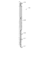
次に、前扉枠13について図1,図5を参照しつつ説明する。なお、図5は、前扉枠13の背面図である。   Next, the front door frame 13 will be described with reference to FIGS. 5 is a rear view of the front door frame 13. As shown in FIG.

前扉枠13には遊技領域のほぼ全域を前方から視認することができるようにした視認窓としての窓部101が形成されている。窓部101は、円形に近い略楕円形状をなし、より詳しくは、その左右側の略中央部が上下側に比べて緩やかに湾曲した形状となっている。なお、前記略中央部が直線状になる形状であってもよい。前扉枠13の窓部101上方において、最も狭い部位のフレーム幅は約61mmである。本実施の形態における上記フレーム幅寸法は、本体枠12において外レール部52の最上部(遊技領域の上端)と本体枠12の上端との間の距離とほぼ一致するものであって、85mm〜95mm程度の上記フレーム幅を有する従来機種に比べて著しく短くなっている。これにより、遊技領域における上部領域の視認性が確保されやすくなると共に、大型の可変表示ユニット35も比較的上方に配置することができるようになっている。窓部101上方のフレーム幅(最狭部位)の寸法は80mm以下であることが望ましく、より望ましくは70mm以下であり、さらに望ましくは60mm以下である。もちろん、所定の強度が確保できるのであれば、50mm以下としても差し支えない。   The front door frame 13 is formed with a window portion 101 as a visual recognition window in which almost the entire game area can be visually recognized from the front. The window portion 101 has a substantially elliptical shape close to a circular shape, and more specifically, a substantially central portion on the left and right sides thereof is gently curved as compared with the upper and lower sides. The substantially central portion may have a linear shape. The frame width of the narrowest portion of the front door frame 13 above the window portion 101 is about 61 mm. The frame width dimension in the present embodiment is substantially equal to the distance between the top of the outer rail portion 52 (the upper end of the game area) of the main frame 12 and the upper end of the main frame 12, Compared to the conventional model having the above frame width of about 95 mm, it is extremely short. As a result, the visibility of the upper area in the game area is easily secured, and the large-sized variable display unit 35 can also be arranged relatively upward. The dimension of the frame width (the narrowest portion) above the window portion 101 is preferably 80 mm or less, more preferably 70 mm or less, and still more preferably 60 mm or less. Of course, as long as a predetermined strength can be secured, it may be 50 mm or less.

前扉枠13の左右のフレーム部分は、フレーム幅を小さくするには制約があり、前扉枠13自体の強度及びガラス支持強度を確保するのに十分な幅寸法を必要とする。本実施の形態では、左右の各フレーム部分において最も狭い部位のフレーム幅を何れも約44mmとしている。この場合、本パチンコ機10にあっては遊技領域を大幅に拡張したことから、パチンコ機10の正面から見て左側すなわち開閉軸線側では、前扉枠13のフレーム幅が上記の通り約44mmとなるのに対し、レールユニット50の外レール部52の左端位置と本体枠12の左端位置との距離が約21mmとなり、後者の寸法がかなり小さいものとなっている。つまり本構成では、前扉枠13を閉鎖した状態において、球案内通路の一部が、前扉枠13の左側フレーム部分と重複し覆い隠されるようになる。しかしながら、球案内通路において遊技球が一時的に視認困難となったとしても、かかる球案内通路は遊技球が遊技領域に案内されるまでの通過領域に過ぎず、遊技者が主として遊技を楽しむ遊技領域において遊技球が視認困難となるわけではない。そのため、実際の遊技に際しては何ら支障が生じない。以上により、前扉枠13の十分な強度及びガラス支持強度を確保しつつも、遊技に何ら支障を及ぼすことなく遊技領域の拡張が可能となる。   The left and right frame portions of the front door frame 13 have limitations in reducing the frame width, and require a width dimension sufficient to secure the strength of the front door frame 13 itself and the glass supporting strength. In the present embodiment, the frame width of the narrowest portion in each of the left and right frame portions is about 44 mm. In this case, since the gaming area is greatly expanded in the pachinko machine 10, the frame width of the front door frame 13 is about 44 mm as described above on the left side, ie, the opening / closing axis side when viewed from the front of the pachinko machine 10. On the other hand, the distance between the left end position of the outer rail portion 52 of the rail unit 50 and the left end position of the main body frame 12 is about 21 mm, and the latter dimension is considerably small. That is, in the present configuration, when the front door frame 13 is closed, a part of the ball guide passage overlaps and is hidden from the left side frame portion of the front door frame 13. However, even if the game ball is temporarily difficult to view in the ball guide passage, such ball guide passage is only a passing area until the game ball is guided to the game area, and a game in which the player enjoys the game mainly It is not always difficult for the game ball to be visible in the area. Therefore, there is no hindrance at the time of an actual game. As described above, the game area can be expanded without affecting the game at all while securing sufficient strength and glass supporting strength of the front door frame 13.

前扉枠13の下端部における左右両側には、本体枠12表面や遊技盤30表面等(証紙等を含む)の一部を視認できるよう透明樹脂を取り付けた小窓107が設けられている。小窓107に取り付けられる透明樹脂は、その内部の証紙等を工場等で容易に機械読み取りできるよう平坦状に構成される。但し、小窓107に、内部の証紙等をホール作業者等が容易に目視できるよう拡大レンズ部を設けることも可能である。   On the left and right sides of the lower end portion of the front door frame 13, small windows 107 are provided with a transparent resin so that a part of the surface of the main body frame 12, the surface of the game board 30, etc. (including a certificate) can be viewed. The transparent resin attached to the small window 107 is configured to be flat so that the inside thereof can be easily machine-read at a factory or the like. However, it is also possible to provide the small window 107 with a magnifying lens portion so that a hole worker or the like can easily view the inside of a certificate stamp or the like.

前扉枠13にはその周囲(例えばコーナー部分)に各種ランプ等の発光手段が設けられている。これら発光手段は、大当たり状態下や所定のリーチ演出時等において点灯、点滅のように発光態様が変更制御されることにより、遊技中の演出効果を高める役割を果たす。例えば、窓部101の周縁に沿ってLED等の発光手段を内蔵した環状電飾部102が左右対称に設けられ、環状電飾部102の中央であってパチンコ機10の最上部にはLED等の発光手段を内蔵した中央電飾部103が設けられている。本パチンコ機10では、中央電飾部103が大当たりランプとして機能し、大当たり状態下で点灯や点滅を行うことにより大当たり状態に移行していることを報知する。また、上皿23周りにも、同じくLED等の発光手段を内蔵した上皿電飾部104が設けられている。その他、中央電飾部103の左右側方には、賞球払出中に点灯する賞球ランプ105と所定のエラー時に点灯するエラー表示ランプ106とがそれぞれ設けられている。なお、環状電飾部102は、内外二重の樹脂カバー層とその内側に収容された発射板付き発光体(LED)とよりなり、樹脂カバー層の各々の内側面には各層で縦横に交差する向きに突条(又は波状の突起)が設けられている。外側の樹脂カバー層は透明であり、内側の樹脂カバー層は有色である。従って、環状電飾部102を発光させれば、多数に分散化された状態、又は立体感を伴った状態の電飾が実現できるようになる。樹脂カバー層には、ガラス粉末入りの樹脂材料を用いると良い。このような樹脂カバー層の構成は、他の電飾部(例えば中央電飾部103や賞球ランプ105)に適用することもできる。   The front door frame 13 is provided with light emitting means such as various lamps around its periphery (for example, a corner portion). These light emitting means play a role of enhancing the rendering effect during the game by changing and controlling the light emission mode such as lighting and blinking in a big hit state or a predetermined reach effect. For example, along the periphery of the window portion 101, an annular illumination part 102 incorporating light emitting means such as an LED is provided symmetrically in the left-right direction, and an LED or the like is provided at the center of the annular illumination part 102 and at the top of the pachinko machine 10. A central illumination part 103 incorporating the light emitting means of the present invention is provided. In the pachinko machine 10, the central electric decoration part 103 functions as a big hit lamp, and notifies that it has shifted to the big hit state by performing lighting or blinking under the big hit state. Further, around the upper tray 23, there is also provided an upper tray electronic decoration portion 104 which incorporates a light emitting means such as an LED. In addition, on the left and right sides of the central illumination part 103, there are respectively provided a prize ball lamp 105 which is lit during payout ball payout and an error display lamp 106 which is lit upon a predetermined error. The annular illumination portion 102 is composed of an inner and outer double resin cover layer and a light emitting body with a launch plate (LED) accommodated inside the inner and outer resin cover layers, and each inner side face of the resin cover layer crosses vertically and horizontally at each layer. A ridge (or a wavelike protrusion) is provided in the direction to be moved. The outer resin cover layer is transparent, and the inner resin cover layer is colored. Therefore, when the annular illumination part 102 is made to emit light, illumination in a state of being dispersed in large numbers or in a state with a three-dimensional effect can be realized. It is preferable to use a resin material containing glass powder for the resin cover layer. Such a configuration of the resin cover layer can also be applied to other electric decoration parts (for example, the central electric decoration part 103 and the prize ball lamp 105).

前扉枠13には、窓部101の下方位置に、貸球操作部120が配設されている。貸球操作部120には球貸しボタン121と、返却ボタン122と、度数表示部123とが設けられている。パチンコ機10の側方に配置されたカードユニット(球貸しユニット)に紙幣やカード等を投入した状態で、貸球操作部120によって球貸し操作、カード返却操作及びカード度数の確認を行うことができる。すなわち、球貸しボタン121は、カード等(記録媒体)に記録された情報に基づいて貸出球を得るために操作されるものであり、カード等に残額が存在する限りにおいて貸出球が払い出される。返却ボタン122は、カードユニットに挿入されたカード等の返却を求める際に操作される。度数表示部123はカード等の残額情報を表示するものである。なお、カードユニットを介さずに球貸し装置等から上皿に遊技球が直接貸し出されるパチンコ機(いわゆる現金機)では貸球操作部120が不要となるが、かかる場合には、貸球操作部120の設置部分に飾りシール等が付されるようになっている。これにより、貸球操作部120を設けた本パチンコ機10の構成において、カードユニットを用いたパチンコ機(いわゆるCR機)と現金機との共用が可能となる。   In the front door frame 13, a ball rental operation unit 120 is disposed below the window portion 101. The ball rental operation unit 120 is provided with a ball rental button 121, a return button 122, and a frequency display unit 123. In a state where a bill, a card, etc. are inserted into a card unit (ball lending unit) disposed to the side of the pachinko machine 10, the ball lending operation, the card returning operation, and the card frequency confirmation may be performed by the rental ball operation unit 120. it can. That is, the ball lending button 121 is operated to obtain a loaned ball based on the information recorded on the card or the like (recording medium), and the loaned ball is paid out as long as the remaining amount is present on the card or the like. The return button 122 is operated to request return of a card or the like inserted in the card unit. The frequency display unit 123 displays balance information of a card or the like. In addition, with pachinko machines (so-called cash machines) in which gaming balls are directly lent out to the upper tray from a ball lending device or the like without passing through a card unit, the ball rental operation unit 120 becomes unnecessary. A decorative seal or the like is attached to the installation portion 120. As a result, in the configuration of the pachinko machine 10 provided with the rental ball operation unit 120, it becomes possible to share a pachinko machine (a so-called CR machine) using a card unit with a cash machine.

前扉枠13の裏側には、窓部101を囲むようにして金属製の各種補強部材が設けられている。詳しくは、図5に示すように、前扉枠13の裏側にあって窓部101の左右及び上下の外側にはそれぞれ補強板131,132,133,134が取り付けられている。これら補強板131〜134は相互に接触して連結されているが、図の左側及び上側の補強板132,133の連結部には直接の接触を避けるための樹脂パーツ135が介在されている。これにより、補強板131〜134による電気経路の閉じたループが切断され、ノイズの原因となる磁界の発生等が防止されている。   Various reinforcing members made of metal are provided on the back side of the front door frame 13 so as to surround the window portion 101. Specifically, as shown in FIG. 5, reinforcing plates 131, 132, 133, and 134 are attached to the back of the front door frame 13 and to the left, right, upper and lower sides of the window portion 101, respectively. The reinforcing plates 131 to 134 are connected in contact with each other, but a resin part 135 for avoiding direct contact is interposed at the connecting portion of the reinforcing plates 132 and 133 on the left side and the upper side of the figure. As a result, the closed loop of the electrical path by the reinforcing plates 131 to 134 is broken, and the generation of the magnetic field that causes noise is prevented.

図5の右側となる開閉軸線側の補強板131にはその上端部及び下端部に、本体枠12に対する組付機構として、組付金具151,152が取り付けられている。そして、本体枠12側の支持金具81,82(図3参照)に対して前扉枠13側の組付金具151,152が取り付けられている。すなわち、下側の組付金具152には下面に開口する軸穴が形成されており、その軸穴に下側の支持金具82の突起軸84が挿入される一方、上側の組付金具151の軸部が上側の支持金具81の支持孔83に挿入されることにより、本体枠12に対して前扉枠13が開閉可能に支持されている。また、同補強板131にはその中間位置にフック状をなす係合爪131aが設けられており、この係合爪131aは、前扉枠13を閉じた状態で本体枠12の孔部12a(図3参照)に挿入されるように構成されている。これにより、上皿23を含む形態で前扉枠13を構成し、その上下の軸支間隔を長くした本パチンコ機10においても、中間位置における前扉枠13の浮き上がりが防止できる。それ故、前扉枠13を浮かしての不正行為等が抑制されるようになっている。   Mounting brackets 151 and 152 are attached to the upper and lower end portions of the reinforcing plate 131 on the opening and closing axis side, which is the right side in FIG. The mounting brackets 151 and 152 on the front door frame 13 side are attached to the support brackets 81 and 82 (see FIG. 3) on the main body frame 12 side. That is, the lower mounting bracket 152 is formed with an axial hole opening to the lower surface, and the projection shaft 84 of the lower support bracket 82 is inserted into the axial hole, while the upper mounting bracket 151 is The front door frame 13 is supported so as to be able to open and close with respect to the main body frame 12 by inserting the shaft portion into the support hole 83 of the upper support fitting 81. Further, the reinforcing plate 131 is provided with a hook-like engaging claw 131a at an intermediate position, and the engaging claw 131a is a hole 12a of the main body frame 12 in a state where the front door frame 13 is closed. (See FIG. 3). As a result, the front door frame 13 is configured to include the upper plate 23, and the front door frame 13 can be prevented from rising at the intermediate position even in the pachinko machine 10 in which the distance between the upper and lower shafts is long. Therefore, the injustice etc. which float the front door frame 13 are controlled.

図5の左側となる開閉軸線とは反対側の補強板132には鉤形状をなす上下一対の鉤金具155,156が取り付けられている。これら鉤金具155,156は、後方に延び、本体枠12に設けた挿入孔87,88(図3参照)に対応するようにして設けられている。本体枠12に対して前扉枠13を閉鎖した際、鉤金具155,156が本体枠12側の挿入孔87,88に挿入されて施錠装置により施錠状態とされるようになっている。   A pair of upper and lower hook fittings 155 and 156 having a hook shape is attached to the reinforcing plate 132 on the opposite side to the opening / closing axis which is the left side of FIG. The hooks 155 and 156 extend rearward and are provided to correspond to the insertion holes 87 and 88 (see FIG. 3) provided in the main body frame 12. When the front door frame 13 is closed with respect to the main body frame 12, the hook metal fittings 155, 156 are inserted into the insertion holes 87, 88 on the main body frame 12 side, and are locked by the locking device.

下側の補強板134には、前記発射レール61に対向する位置に樹脂ケース136が取り付けられている。樹脂ケース136には、前記貸球操作部120用の回路基板が収容されている。樹脂ケース136の背面(図5に見える面)は平坦状をなし、前扉枠13を閉じた際に発射レール61の側壁を構成するようになっている。故に、発射レール61から遊技球が前方にこぼれ落ちることが防止される。   A resin case 136 is attached to the lower reinforcing plate 134 at a position facing the firing rail 61. The resin case 136 accommodates a circuit board for the ball rental operation unit 120. The back surface (surface seen in FIG. 5) of the resin case 136 is flat, and when the front door frame 13 is closed, the side wall of the firing rail 61 is configured. Therefore, the game ball is prevented from falling forward from the firing rail 61.

下側の補強板134の一部を切り欠いた部位には、パチンコ機10後方に向けて球通路樋138が設置されており、球通路樋138の少なくとも上方には、同じくパチンコ機10後方に向けて延びる庇(ひさし)部139が設けられている。この場合、本体枠12側に前扉枠13を閉じた状態では、球通路樋138と庇部139との間に、本体枠12側の連通口72上辺に沿って延びる突条が入り込むようにして配置される。故に、球通路樋138より針金やフィルム等を侵入させて不正行為を行おうとしても、遊技領域にまで針金やフィルム等を侵入させることが非常に困難となる。結果として、針金やフィルム等を利用して行われる不正行為を防止することができる。   A ball passage rod 138 is installed toward the rear of the pachinko machine 10 at a portion where a part of the lower reinforcing plate 134 is cut away, and at least above the ball passage rod 138, similarly to the rear of the pachinko machine 10 An eave (eaves) portion 139 is provided to extend. In this case, when the front door frame 13 is closed to the main body frame 12 side, a ridge extending along the upper side of the communication port 72 on the main body frame 12 side is inserted between the ball passage 球 138 and the collar portion 139 Will be placed. Therefore, even if a wire, a film, or the like is made to intrude from the ball passage 樋 138 to perform an illegal act, it becomes very difficult to make the wire, the film, etc. enter the game area. As a result, it is possible to prevent fraudulent acts performed using wires, films and the like.

上述した補強板131〜134はガラス支持用の金枠としての機能も兼ね備えており、これら補強板131〜134の内側が後方に折り返されてガラス保持溝が形成されている。ガラス保持溝は前後に2列形成されており、矩形状をなす前後一対のガラス137が各ガラス保持溝にて保持される。これにより、2枚のガラス137が前後に所定間隔を隔てて取着されている。   The above-described reinforcing plates 131 to 134 also have a function as a metal frame for supporting glass, and the inner side of these reinforcing plates 131 to 134 is folded back to form a glass holding groove. The glass holding grooves are formed in two rows in the front and rear direction, and a pair of rectangular front and rear glasses 137 are held by the respective glass holding grooves. Thereby, two sheets of glass 137 are attached at predetermined intervals in front and back.

前述した通り本実施の形態のパチンコ機10では遊技領域の拡張を図っていることから、前扉枠13を閉じた状態にあっては、内外のレール部51,52間に形成された球案内通路の一部が前扉枠13により覆い隠される構成となっている。それ故、球案内通路では手前側の開放部がガラス137で覆えない部分ができてしまう。かかる場合、例えば、遊技球発射装置より発射された遊技球が戻り球防止部材54まで至らず戻ってくると、遊技球が球案内通路外に飛び出したり、外レール部52とガラス137との間にできる隙間に挟まってしまうおそれがある。そこで本実施の形態では、前扉枠13に、球案内通路の手前側開放部を被覆するためのレールカバー140を取り付けている。レールカバー140は略円弧状をなす板体であって、透明な樹脂により形成されている。レールカバー140は、その円弧形状が前記球案内通路の形状に対応しており、窓部101の周縁部に沿って、球案内通路の基端部から先端部近傍までの区間を覆うようになっている。特にレールカバー140の内径側の寸法・形状は内レール部51のそれにほぼ一致する。また、レールカバー140の右端部(すなわち、レールカバー140を前扉枠13に取着した図5の状態で右端となる部位)には、球案内通路がガラス137の側縁部からはみ出した部分を被覆するための被覆部141が設けられている。以上のレールカバー140の構成により、前扉枠13が閉じられた状態においては、レールカバー140の裏面が球案内通路のほぼ全域を覆うこととなって、遊技球が球案内通路外に飛び出したり、外レール部52とガラス137との間にできる隙間に挟まってしまうといった不具合の発生を防止することができる。   As described above, in the pachinko machine 10 of the present embodiment, the game area is expanded, so when the front door frame 13 is closed, the ball guide formed between the inner and outer rail portions 51 and 52 A part of the passage is covered by the front door frame 13. Therefore, in the ball guiding passage, there is a portion where the open portion on the front side can not be covered by the glass 137. In such a case, for example, when the game ball fired from the game ball launch device comes back without reaching the return ball preventing member 54, the game ball may jump out of the ball guiding passage, or between the outer rail portion 52 and the glass 137 There is a risk of being caught in the gap that can be So, in this embodiment, the rail cover 140 for covering the front side opening part of a ball | bowl guide passage is attached to the front door frame 13. As shown in FIG. The rail cover 140 is a plate having a substantially arc shape, and is formed of a transparent resin. The arc shape of the rail cover 140 corresponds to the shape of the ball guide passage, and covers the section from the base end portion of the ball guide passage to the vicinity of the tip portion along the peripheral portion of the window portion 101. ing. In particular, the size and shape of the inner diameter side of the rail cover 140 substantially match that of the inner rail portion 51. Further, at the right end of the rail cover 140 (that is, the portion which becomes the right end in the state of FIG. 5 in which the rail cover 140 is attached to the front door frame 13), a portion where the ball guiding passage protrudes from the side edge of the glass 137 A covering portion 141 for covering the With the above-described configuration of the rail cover 140, when the front door frame 13 is closed, the back surface of the rail cover 140 covers almost the entire area of the ball guiding passage, and the gaming ball jumps out of the ball guiding passage It is possible to prevent the occurrence of a defect such as being caught in the gap formed between the outer rail portion 52 and the glass 137.

また、レールカバー140の下部裏側には、その内側縁に沿って円弧状に延び且つ後方へ向けて突出する突条142が形成されている。突条142は、前扉枠13が閉じられた状態において、球案内通路内に入り込んだ状態で内レール部51に重なり合うように配置される。従って、例えば前扉枠13と本体枠12との隙間から針金やフィルム等を侵入させて不正行為を行おうとしても、球案内通路の内側にある遊技領域にまで針金やフィルム等を侵入させることが非常に困難となる。その結果、針金やフィルム等を利用して行われる不正行為を防止することができる。なお、突条142をより広い範囲で、例えばレールカバー140の内側縁の全域に沿って形成する構成としても良く、かかる構成によれば、より広い範囲で針金やフィルム等を侵入させにくくなり、針金やフィルム等を利用して行われる不正行為をより確実に防止することができる。   Further, on the lower rear side of the rail cover 140, there is formed a protrusion 142 extending in an arc shape along the inner edge thereof and protruding rearward. The protrusion 142 is disposed so as to overlap the inner rail portion 51 in a state in which it is in the ball guide passage when the front door frame 13 is closed. Therefore, for example, even if it is attempted to intrude a wire, a film, or the like from the gap between the front door frame 13 and the main body frame 12 to perform an illegal act, the wire, the film, or the like may intrude into the game area inside the ball guiding passage. Will be very difficult. As a result, it is possible to prevent fraudulent acts performed using wires, films and the like. The protrusion 142 may be formed in a wider range, for example, along the entire inner edge of the rail cover 140. According to such a configuration, it is difficult for the wire, the film, etc. to penetrate in the wider range. It is possible to more reliably prevent fraudulent acts performed using wires, films and the like.

次に、パチンコ機10の背面の構成を説明する。なお、図6はパチンコ機10の背面図、図7はパチンコ機10の背面構成を主要部品毎に分解して示す分解斜視図である。   Next, the configuration of the back of the pachinko machine 10 will be described. 6 is a rear view of the pachinko machine 10, and FIG. 7 is an exploded perspective view showing the rear face configuration of the pachinko machine 10 for each of the main parts.

まず、パチンコ機10の背面構成について全体の概要を説明する。パチンコ機10の背面側には、各種制御装置(各種制御基板)が上下左右に並べられるようにして又は前後に重ねられるようにして配置されるとともに、遊技球を供給するための遊技球供給装置(払出機構)や樹脂製の保護カバー等が取り付けられている。本実施の形態では、各種制御装置を2つの取付台に分けて搭載して2つの制御基板ユニットを構成し、それら制御基板ユニットを個別に本体枠12又は遊技盤30の裏面に装着するようにしている。この場合、主制御装置271(主基板)と音声ランプ制御装置272(音声ランプ制御基板)とを一方の取付台に搭載してユニット化すると共に、払出制御装置311(払出制御基板)、発射制御装置312(発射制御基板)及び電源装置313(電源基板)を他方の取付台に搭載してユニット化している。以下においては、便宜上、前者のユニットを「第1制御基板ユニット201」と称し、後者のユニットを「第2制御基板ユニット202」と称することとする。また、払出機構及び保護カバーも1ユニットとして一体化され、一般に樹脂部分を裏パックと称することもあるため、ここではそのユニットを「裏パックユニット203」と称する。各ユニット201〜203の詳細な構成については後述する。   First, an overview of the entire rear surface configuration of the pachinko machine 10 will be described. On the back side of the pachinko machine 10, various control devices (various control boards) are arranged side by side vertically or horizontally or stacked one on top of the other, and a game ball supply device for supplying gaming balls (Discharge mechanism) and a protective cover made of resin are attached. In the present embodiment, various control devices are divided into two mounts and mounted to configure two control board units, and the control board units are individually attached to the back of the main body frame 12 or the game board 30. ing. In this case, the main controller 271 (main substrate) and the voice lamp control device 272 (voice lamp control substrate) are mounted on one of the mounts to be unitized, and a payout control device 311 (dispense control substrate) The device 312 (emission control substrate) and the power supply 313 (power supply substrate) are mounted on the other mounting base to be unitized. Hereinafter, for convenience, the former unit will be referred to as “first control board unit 201”, and the latter unit will be referred to as “second control board unit 202”. Further, since the dispensing mechanism and the protective cover are also integrated as one unit, and the resin portion may be generally referred to as a back pack, the unit will be referred to as a "back pack unit 203" herein. The detailed configuration of each of the units 201 to 203 will be described later.

第1制御基板ユニット201、第2制御基板ユニット202及び裏パックユニット203は、ユニット単位で何ら工具等を用いずに着脱できるよう構成されるとともに、一部に支軸部を設けて本体枠12又は遊技盤30の裏面に対して展開できる構成となっている。これは、各ユニット201〜203やその他構成が前後に重ねて配置された場合に隠れた部位を容易に確認することを可能とするための工夫でもある。実際には、図8の概略図に示すように、略L字状をなす第1制御基板ユニット201はパチンコ機10のほぼ中央に配置され、その下方に第2制御基板ユニット202が配置されている。また、第1制御基板ユニット201に一部重複する領域に、裏パックユニット203が配置されている。   The first control board unit 201, the second control board unit 202, and the back pack unit 203 can be attached and detached without using a tool etc. in unit units, and at the same time, a spindle is provided in the main body frame Alternatively, it can be developed to the back of the game board 30. This is also a device for making it possible to easily confirm a hidden portion when the units 201 to 203 and other components are arranged one on top of the other. In practice, as shown in the schematic view of FIG. 8, the substantially L-shaped first control board unit 201 is disposed substantially at the center of the pachinko machine 10, and the second control board unit 202 is disposed therebelow. There is. Further, the back pack unit 203 is disposed in an area partially overlapping the first control substrate unit 201.

第1制御基板ユニット201にはパチンコ機10の背面から見て左端部に支軸部M1が設けられ、その支軸部M1による軸線Aを中心に第1制御基板ユニット201が回動可能となっている。また、第1制御基板ユニット201には、その右端部すなわち支軸部M1の反対側となる開放端側に、ナイラッチ(登録商標)等よりなる締結部M2が設けられると共に上端部に係止爪部M3が設けられており、これら締結部M2及び係止爪部M3によって第1制御基板ユニット201がパチンコ機10本体の裏面に沿った状態に保持されるようになっている。また、第2制御基板ユニット202にはパチンコ機10の背面から見て右端部に支軸部M4が設けられ、その支軸部M4による軸線Bを中心に第2制御基板ユニット202が回動可能となっている。また、第2制御基板ユニット202には、その左端部すなわち支軸部M4の反対側となる開放端側に、ナイラッチ等よりなる締結部M5が設けられており、この締結部M5によって第2制御基板ユニット202がパチンコ機10本体の裏面に沿った状態に保持されるようになっている。さらに、裏パックユニット203にはパチンコ機10の背面から見て右端部に支軸部M6が設けられ、その支軸部M6による軸線Cを中心に裏パックユニット203が回動可能となっている。また、裏パックユニット203には、その左端部すなわち支軸部M6の反対側となる開放端側にナイラッチ等よりなる締結部M7が設けられるとともに、上端部及び下端部にそれぞれ回動式の係止部M8,M9が設けられており、これら締結部M7及び係止部M8,M9によって裏パックユニット203がパチンコ機10本体の裏面に沿った状態に保持されるようになっている。   The first control board unit 201 is provided with a pivot M1 at the left end when viewed from the back of the pachinko machine 10, and the first control board unit 201 can rotate about an axis A by the spindle M1. ing. Further, in the first control board unit 201, a fastening portion M2 made of ny latch (registered trademark) or the like is provided on the right end portion, that is, the open end side opposite to the support shaft portion M1 and A portion M3 is provided, and the first control board unit 201 is held along the back surface of the pachinko machine 10 main body by the fastening portion M2 and the locking claw portion M3. Further, the second control board unit 202 is provided with a support shaft portion M4 at the right end when viewed from the back surface of the pachinko machine 10, and the second control board unit 202 can rotate about an axis B by the support shaft portion M4. It has become. Further, the second control board unit 202 is provided with a fastening portion M5 comprising a ny latch etc. on the left end portion, that is, the open end side opposite to the support shaft portion M4, and the second control is performed by the fastening portion M5. The substrate unit 202 is held along the back surface of the pachinko machine 10 main body. Further, the back pack unit 203 is provided with a support shaft portion M6 at the right end when viewed from the back of the pachinko machine 10, and the back pack unit 203 is rotatable around an axis C by the support shaft portion M6. . Further, the back pack unit 203 is provided with a fastening portion M7 comprising a ny latch etc. on the left end portion, that is, the open end side opposite to the support shaft portion M6, and also has rotational engagement at the upper end and the lower end. Stop portions M8 and M9 are provided, and the back pack unit 203 is held along the back surface of the pachinko machine 10 main body by the fastening portion M7 and the locking portions M8 and M9.

各ユニット201〜203を回動可能に支持する支軸部M1,M4,M6は、各ユニット201〜203をパチンコ機10の裏面から開いた状態で容易に取り外し可能なヒンジ構造となっている。簡単に説明すると、第1制御基板ユニット201については、締結部M2の締結及び係止爪部M3の係止を解除すると共に、当該ユニット201を軸線Aを中心に回動させて展開し、その状態で持ち上げる。これにより、裏パックユニット203がない前提であれば、第1制御基板ユニット201を取り外すことができる。また、第2制御基板ユニット202については、締結部M5の締結を解除すると共に、当該ユニット202を軸線Bを中心に回動させて展開し、その状態で持ち上げる。これにより、第2制御基板ユニット202を取り外すことができる。さらに、裏パックユニット203については、締結部M7の締結及び係止部M8,M9の係止を解除すると共に、当該ユニット203を軸線Cを中心に回動させて展開し、その状態で持ち上げる。これにより、裏パックユニット203を取り外すことができる。   Support shaft portions M1, M4, and M6 rotatably supporting the units 201 to 203 have a hinge structure which can be easily removed in a state where the units 201 to 203 are opened from the back surface of the pachinko machine 10. Briefly explaining, with regard to the first control board unit 201, the fastening of the fastening portion M2 and the locking of the locking claw portion M3 are released, and the unit 201 is rotated about the axis A to expand and Lift in the state. Thus, on the premise that there is no back pack unit 203, the first control board unit 201 can be removed. In addition, with regard to the second control board unit 202, the fastening of the fastening portion M5 is released, and the unit 202 is rotated about the axis B to be developed, and is lifted in that state. Thereby, the second control board unit 202 can be removed. Further, with regard to the back pack unit 203, the fastening of the fastening portion M7 and the locking of the locking portions M8 and M9 are released, and the unit 203 is rotated about the axis C to unfold, and lifted in that state. Thereby, the back pack unit 203 can be removed.

ここで、各ユニット201〜203の展開方向は同一でなく、第1制御基板ユニット201は、パチンコ機10の背面から見て左開きになるのに対し、第2制御基板ユニット202及び裏パックユニット203は、同右開きになるよう構成されている。この場合、第1制御基板ユニット201は、裏パックユニット203に一部重複して設けられるため、裏パックユニット203を開かないことには第1制御基板ユニット201を取り外すことが不可能であり、さらに言うと、第1制御基板ユニット201及び裏パックユニット203が各々逆方向に展開する構成であるため、裏パックユニット203を所定角度以上に大きく開いた状態又は同ユニット203を取り外した状態でなければ第1制御基板ユニット201を取り外すことが不可能である。従って、第1制御基板ユニット201を取り外すことに着目すると、他のユニット202,203に比べて取り外しが困難な構成となっている。さらに、施錠装置をキー操作して外枠11に対して本体枠12を開放しなければ、裏パックユニット203を開くことができない構成となっているため、より一層第1制御基板ユニット201の取り外しが困難なものとなっている。より具体的な構成については後述する。   Here, the expansion directions of the units 201 to 203 are not the same, and the first control board unit 201 is opened left as viewed from the back of the pachinko machine 10, whereas the second control board unit 202 and the back pack unit The reference numeral 203 is configured to be open to the right. In this case, since the first control board unit 201 is partially overlapped with the back pack unit 203, the first control board unit 201 can not be removed without opening the back pack unit 203, Furthermore, since the first control board unit 201 and the back pack unit 203 are each deployed in the opposite direction, the back pack unit 203 must be opened wide by a predetermined angle or more, or the unit 203 must be removed. For example, it is impossible to remove the first control board unit 201. Therefore, focusing on the removal of the first control board unit 201, removal is more difficult than the other units 202 and 203. Furthermore, since the back pack unit 203 can not be opened unless the main frame 12 is opened with respect to the outer frame 11 by key operation of the locking device, the first control board unit 201 can be further removed. Has become difficult. A more specific configuration will be described later.

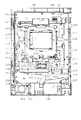
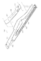
次に、本体枠12及び遊技盤30の裏面構成を説明する。なお、図9は本体枠12に遊技盤30を組み付けた状態でかつ前記各ユニット201〜203等を取り外した状態の構成を示す背面図、図10は本体枠12を後方より見た斜視図、図11は遊技盤30を後方より見た斜視図である。   Next, the back side structure of the main body frame 12 and the game board 30 will be described. 9 is a rear view showing a configuration in which the game board 30 is assembled to the main body frame 12 and the units 201 to 203 are removed, and FIG. 10 is a perspective view of the main body frame 12 as viewed from the rear. FIG. 11 is a perspective view of the game board 30 as viewed from the rear.

遊技盤30は、樹脂ベース25に囲まれた四角枠状の設置領域に裏面側より設置され、本体枠12に設けられた複数(本実施の形態では4カ所)の係止固定具211,212によって後方へ脱落しないように固定されている。係止固定具211,212は手動で回動操作することができ、固定位置(ロック位置)と固定解除位置(アンロック位置)とに切り換えることができるよう構成されている。図9にはロック状態を示す。左右3カ所の係止固定具211は金属片を折り曲げ形成したL型の金具であり、遊技盤30の固定状態で本体枠12の外方へ張り出さないよう構成されている。なお、下部1カ所の係止固定具212は合成樹脂製のI型の留め具である。   The game board 30 is installed from the back side in a rectangular frame-shaped installation area surrounded by the resin base 25 and a plurality of (four in the present embodiment) locking fixtures 211 and 212 provided on the main body frame 12. Is fixed so as not to fall backward by The locking fixtures 211 and 212 can be manually rotated, and can be switched between a fixed position (lock position) and a fixed release position (unlocked position). FIG. 9 shows the locked state. The right and left three locking fixtures 211 are L-shaped brackets formed by bending metal pieces, and are configured not to protrude outward of the main body frame 12 when the game board 30 is fixed. The lower one of the locking fixtures 212 is an I-shaped fastener made of synthetic resin.

遊技盤30の中央に配置される可変表示ユニット35には、センターフレーム43(図4参照)を背後から覆う合成樹脂製のフレームカバー213が後方に突出して設けられており、そのフレームカバー213の後端に、図柄表示装置41と表示制御手段としての表示制御装置214とが前後に重ねられた状態で着脱可能に取り付けられている。フレームカバー213内には、センターフレーム43に内蔵されたLED等を駆動するためのLED制御基板などが配設されている。   The variable display unit 35 disposed at the center of the game board 30 is provided with a frame cover 213 made of a synthetic resin, which covers the center frame 43 (see FIG. 4) from behind, projecting backward. At the rear end, a symbol display device 41 and a display control device 214 as display control means are detachably mounted in a state of being overlapped in the front and back. In the frame cover 213, an LED control board for driving an LED or the like built in the center frame 43 is disposed.

遊技盤30の裏面には、可変表示ユニット35を取り囲むようにして集合板ユニット215が設けられている。集合板ユニット215は、薄板状の枠体として例えばABS樹脂等の合成樹脂により成形されるベースを有し、そのベース面が遊技盤30の裏面に当接されるようにして取り付けられている。集合板ユニット215には、各種入賞口に入賞した遊技球を回収するための遊技球回収機構や、各種入賞口等への遊技球の入賞を検知するための入賞検知機構などが設けられている。   A collective board unit 215 is provided on the back of the game board 30 so as to surround the variable display unit 35. The collecting plate unit 215 has a base formed of a synthetic resin such as ABS resin as a thin plate-like frame, and is attached so that the base surface is in contact with the back surface of the game board 30. The collecting plate unit 215 is provided with a game ball collecting mechanism for collecting game balls that have won in various winning openings, and a winning detection mechanism for detecting winning of gaming balls in various winning openings and the like. .

遊技球回収機構について説明すると、集合板ユニット215の下方には、前記一般入賞口31、各可変入賞装置32a,32b、作動口33の遊技盤開口部に対応し且つ下流側で1カ所に集合する回収通路216が形成されている。また、遊技盤30の下方には、本体枠12にポリカーボネート樹脂等の合成樹脂製の排出通路盤217が取り付けられており、排出通路盤217には排出球をパチンコ機10外部の例えば遊技ホールの島設備等へ案内するための排出通路218が形成されている。従って、図9に仮想線で例示するように、一般入賞口31等に入賞した遊技球は何れも集合板ユニット215の回収通路216を介して集合し、さらに排出通路盤217の排出通路218を介してパチンコ機10外部に排出される。なお、アウト口36も同様に排出通路218に通じており、何れの入賞口にも入賞しなかった遊技球も排出通路218を介してパチンコ機10外部に排出される。上記構成では、遊技盤30の下端面を境界にして、上方に集合板ユニット215(回収通路216)が、下方に排出通路盤217(排出通路218)が設けられており、排出通路盤217が遊技盤30に対して前後方向に重複していない。従って、遊技盤30を本体枠12から取り外す際において、排出通路盤17が遊技盤取り外しの妨げになるといった不都合が生じることもない。   The game ball collecting mechanism will be described. The lower part of the collective plate unit 215 corresponds to the game board opening of the general winning opening 31, the variable winning devices 32a and 32b, and the operation opening 33 and is gathered at one downstream location. A recovery passage 216 is formed. Further, a discharge passage board 217 made of synthetic resin such as polycarbonate resin is attached to the main body frame 12 below the game board 30, and the discharge passage board 217 is provided with a discharge ball outside the pachinko machine 10, for example, in a game hall. A discharge passage 218 for guiding to an island facility or the like is formed. Therefore, as illustrated by the phantom line in FIG. 9, all gaming balls that have won in the general winning opening 31 etc. gather through the collection passage 216 of the collective plate unit 215, and further the discharge passage 218 of the discharge passage board 217 It is discharged to the outside of the pachinko machine 10 through. The out port 36 is also in communication with the discharge passage 218, and the game balls that did not win in any of the winning openings are discharged to the outside of the pachinko machine 10 through the discharge passage 218. In the above configuration, the collecting plate unit 215 (collection passage 216) is provided at the upper side with the lower end surface of the game board 30 as a boundary, the discharge passage board 217 (discharge passage 218) is provided below, and the discharge passage board 217 is It does not overlap with the game board 30 in the front-rear direction. Therefore, when the game board 30 is removed from the main frame 12, the discharge passage board 17 does not interfere with the game board removal.

なお、排出通路盤217は、パチンコ機10前面の上皿23の裏側に配置されており、上皿23に至る球排出口(図2の球通路樋138)より針金やフィルム等を差し込み、さらにその針金やフィルム等を本体枠12と排出通路盤217との隙間を通じて遊技領域側に侵入させるといった不正行為が考えられる。そこで、本パチンコ機10では、図10に示すように、排出通路盤217には、球通路樋138の上部位置に対応する高さ位置に、本体枠12に重なり合うようにしてパチンコ機10前方に延びるプレート219を設けた。従って、本体枠12と排出通路盤217との隙間から針金やフィルム等を侵入させようとしてもそれがプレート219にて阻害され、遊技領域にまで針金やフィルム等を侵入させることが非常に困難となる。その結果、針金やフィルム等を利用して可変入賞装置32を強制的に開放する等の不正行為を防止することができる。   The discharge passage board 217 is disposed on the back of the upper plate 23 on the front surface of the pachinko machine 10, and inserts a wire, a film, etc. from the ball discharge port (ball passage (138 in FIG. 2) leading to the upper plate 23. An illegal act may be considered such that the wire, film or the like is made to enter the gaming area side through the gap between the main frame 12 and the discharge passage board 217. Therefore, in the pachinko machine 10, as shown in FIG. 10, the discharge channel board 217 is placed in front of the pachinko machine 10 so as to overlap the main body frame 12 at a height position corresponding to the upper position of the ball channel rod 138. An extending plate 219 was provided. Therefore, even if it is attempted to infiltrate a wire, film or the like from the gap between the main body frame 12 and the discharge passage board 217, it is inhibited by the plate 219, and it is very difficult to infiltrate the wire or film to the game area. Become. As a result, it is possible to prevent fraudulent acts such as forcibly opening the variable winning device 32 using a wire, a film or the like.

入賞検知機構について説明すると、集合板ユニット215には、遊技盤30表側の一般入賞口31と対応する位置に入賞口スイッチ221が設けられ、第1可変入賞装置32aと対応する位置に第1カウントスイッチ223aが設けられ、第2可変入賞装置32bと対応する位置に第2カウントスイッチ223bが設けられている。各カウントスイッチ223a,223bは、対応する可変入賞装置32a,32bに入賞した遊技球の数をカウントするスイッチである。また、作動口33に対応する位置には作動口33への遊技球の入賞を検知する作動口スイッチ224が設けられ、スルーゲート34に対応する位置にはスルーゲート34の遊技球の通過を検知するゲートスイッチ225が設けられている。入賞口スイッチ221及びゲートスイッチ225は電気配線を通じて盤面中継基板226に接続され、第1カウントスイッチ223aは第1大入賞口中継基板227aに接続され、第2カウントスイッチ223bは第2大入賞口中継基板227bに接続されている。そして、盤面中継基板226及び各大入賞口中継基板227a,227bが主制御装置271に接続されている。作動口スイッチ224は中継基板を介さずに直接主制御装置271に接続されている。その他図示は省略するが、各可変入賞装置32a,32bには、それぞれの大入賞口の開閉扉を開放するための大入賞口ソレノイドが設けられ、作動口33には、それに付随する電動役物を開放するための作動口ソレノイドが設けられている。   The winning detection mechanism will be described. In the collective plate unit 215, a winning opening switch 221 is provided at a position corresponding to the general winning opening 31 on the front side of the gaming board 30, and a first count is made at a position corresponding to the first variable winning device 32a. A switch 223a is provided, and a second count switch 223b is provided at a position corresponding to the second variable winning device 32b. Each count switch 223a, 223b is a switch for counting the number of gaming balls that have won the corresponding variable winning device 32a, 32b. In addition, the operation opening switch 224 which detects the winning a prize of the game ball to the operation opening 33 is provided in the position which corresponds to the operation opening 33, passing of the game ball of the through gate 34 is detected in the position which corresponds to the through gate 34 A gate switch 225 is provided. The winning opening switch 221 and the gate switch 225 are connected to the relay board 226 via electrical wiring, the first count switch 223a is connected to the first large winning opening relay board 227a, and the second count switch 223b is relayed to the second large winning opening relay It is connected to the substrate 227b. Then, the board relay board 226 and the special winning opening relay boards 227 a and 227 b are connected to the main controller 271. The operation port switch 224 is directly connected to the main control device 271 without the relay board. Although not shown in the drawings, each variable winning device 32a, 32b is provided with a big winning opening solenoid for opening the opening / closing door of each big winning opening, and the operation opening 33 is accompanied by an electric combination An actuating port solenoid is provided for releasing the

上記入賞検知機構にて各々検出された検出結果は主制御装置271に取り込まれ、該主制御装置271よりその都度の入賞状況に応じた払出指令(遊技球の払出個数)が払出制御装置311に送信される。そして、払出制御装置311の出力により所定数の遊技球の払出が実行されるようになっている。ここで、従来のいわゆる証拠球方式では、各種入賞口に入賞した遊技球を入賞球処理装置に一旦集め、その入賞球処理装置で入賞球の存在を1つずつ順番に確認した上で払出を行うようにしていたが、本実施の形態のパチンコ機10では、各種入賞口毎に遊技球の入賞を電気的に検知して払出が直ちに行われるようにしているため、払い出す遊技球が多量にあってもその払出をいち早く実施することが可能となるとともに、入賞球処理装置が不要となる。   The detection results respectively detected by the above-mentioned prize detection mechanism are taken into main controller 271, and a payout command (the number of paid out game balls) according to the winning situation from that main controller 271 to payout controller 311 Will be sent. Then, the payout of the predetermined number of gaming balls is executed by the output of the payout control device 311. Here, in the conventional so-called evidence ball method, gaming balls that have won various prize winning openings are collected once in the winning ball processing device, and the presence of the winning balls is confirmed in order one by one with the winning ball processing device. In the pachinko machine 10 according to the present embodiment, the game balls are electrically detected for each of the various winning openings and the payout is made immediately, so a large amount of game balls are paid out. Even if it is in, it becomes possible to carry out the payment promptly, and a winning ball processing device becomes unnecessary.

集合板ユニット215には、その右上部に盤用外部端子板230が設けられている。盤用外部端子板230には、第1図柄の変動が停止(確定)する毎に信号出力するための出力端子と、大当たり状態又は第1図柄の変動時間短縮時に信号出力するための出力端子と、大当たり状態下で信号出力するための出力端子とが設けられている。そして、これらの出力端子を通じて、遊技ホール側の管理制御装置に対して遊技(遊技盤30側の状態)に関する信号が出力される。盤用外部端子板230は、取り外し容易な状態で集合板ユニット215に取り付けられている。なお、図9に示すように、本体枠12裏側の左下部には、打球槌等を備えるセットハンドル228及び発射モータ229が設けられている。   A panel external terminal board 230 is provided in the upper right portion of the collective board unit 215. The panel external terminal board 230 has an output terminal for outputting a signal each time the variation of the first symbol is stopped (confirmed), and an output terminal for outputting a signal when the variation time of the big hit state or the first symbol is shortened. And an output terminal for outputting a signal under a jackpot condition. Then, through these output terminals, a signal relating to the game (the state of the game board 30) is output to the management control device on the game hall side. The board external terminal board 230 is attached to the collective board unit 215 in an easily removable state. As shown in FIG. 9, at the lower left portion on the rear side of the main body frame 12, a set handle 228 provided with a bat or the like and a firing motor 229 are provided.

集合板ユニット215には、第1制御基板ユニット201を取り付けるための取付機構が設けられている。具体的には、この取付機構として、遊技盤30の裏面から見て左下隅部には上下方向に延びる軸受け金具231が設けられ、この軸受け金具231には同一軸線上に上下一対の軸受け孔231aが形成されている。また、遊技盤30において、軸受け金具231の右方には上下一対の被締結孔(具体的にはナイラッチの取付孔)232が設けられ、軸受け金具231の上方には係止爪片233が設けられている。   The collecting plate unit 215 is provided with a mounting mechanism for mounting the first control board unit 201. More specifically, as this mounting mechanism, a bearing fitting 231 extending vertically is provided at the lower left corner when viewed from the back surface of the game board 30, and the bearing fitting 231 has a pair of upper and lower bearing holes 231a on the same axis. Is formed. Further, in the game board 30, a pair of upper and lower fastening holes (specifically, a mounting hole for the ny latch) 232 is provided on the right side of the bearing fitting 231, and a locking claw 233 is provided above the bearing fitting 231. It is done.

本体枠12の裏面には、第2制御基板ユニット202や裏パックユニット203を取り付けるための取付機構が設けられている。具体的には、本体枠12にはその右端部に長尺状の軸受け金具235が取り付けられている。この軸受け金具235は補強部材としても機能する。図12に示すように、軸受け金具235は遊技盤30よりも下方へ延びる長尺板状の金具本体236を有し、その金具本体236より後方へ起立させるようにして、下部2カ所に第2制御基板ユニット202用の軸受け部237が形成されると共に、上部2カ所に裏パックユニット203用の軸受け部238が形成されている。これら軸受け部237,238にはそれぞれ同軸の軸受け孔が形成されている。なお、第2制御基板ユニット202用の軸受け部237と裏パックユニット203用の軸受け部238とを各々個別の軸受け金具で構成することも可能である。その他、第2制御基板ユニット202用の取付機構として、本体枠12には、遊技盤30設置領域よりも下方左端部に上下一対の被締結孔(具体的には、ナイラッチの取付孔)239が設けられている。また、裏パックユニット203用の取付機構として、本体枠12には、遊技盤30設置領域の左端部に上下一対の被締結孔(具体的には、ナイラッチの取付孔)240が設けられている。本体枠12において遊技盤30の左上方、右寄り上方及び右寄り下方の各位置には、遊技盤30との間に裏パックユニット203を挟み込んで支持するための回動式の固定具241,242,243がそれぞれ設けられている。なお、裏パックユニット203は、その上部に大量の遊技球を貯留することから、裏パックユニット203の上部を支持するための固定具241,242に関しては特に十分な強度を持つ構成とするのが望ましく、本実施の形態では回動式の固定具を用いている。   An attachment mechanism for attaching the second control board unit 202 and the back pack unit 203 is provided on the back surface of the main body frame 12. Specifically, a long-sized bearing fitting 235 is attached to the right end portion of the main body frame 12. The bearing fitting 235 also functions as a reinforcing member. As shown in FIG. 12, the bearing fitting 235 has a long plate-like fitting main body 236 extending downward from the game board 30, and is erected rearward from the fitting main body 236, and the second lower two places While the bearing part 237 for the control board unit 202 is formed, the bearing part 238 for the back pack unit 203 is formed in two upper places. Coaxial bearing holes are formed in the bearing portions 237 and 238, respectively. Note that the bearing portion 237 for the second control board unit 202 and the bearing portion 238 for the back pack unit 203 can also be configured with individual bearing fittings. In addition, as a mounting mechanism for the second control board unit 202, the main body frame 12 has a pair of upper and lower fastening holes (specifically, mounting holes for the ny latch) 239 at the left end lower than the game board 30 installation area. It is provided. Further, as a mounting mechanism for the back pack unit 203, the main body frame 12 is provided with a pair of upper and lower fastening holes (specifically, mounting holes for the ny latch) 240 at the left end of the game board 30 installation area. . Rotary fixtures 241, 242, for supporting the back pack unit 203 between the game board 30 and the game board 30 at the upper left, upper right, and lower right positions of the game board 30 in the main frame 12. 243 are provided respectively. In addition, since the back pack unit 203 stores a large amount of gaming balls in the upper part, the fixing tools 241 and 242 for supporting the upper part of the back pack unit 203 have a particularly sufficient strength. Desirably, in the present embodiment, a rotating type fixing tool is used.

上記の如く本体枠12の左右一側部(図9では右側部)には長尺状の軸受け金具235が設けられる一方、本体枠12の左右他側部(図9では左側部)には施錠装置が設けられている。施錠装置は、上下方向に延び本体枠12に固定された基枠247と、その基枠247に対して上下方向に移動可能に組み付けられた長尺状の連動杆248とを備え、基枠247の下部に前記シリンダ錠91が一体化されている。連動杆248は、シリンダ錠91の操作により上下いずれかの方向に移動する。連動杆248には、鉤形状をなす上下一対の鉤金具249が設けられており、外枠11に対して本体枠12を閉鎖した際には、鉤金具249が外枠11側の支持金具(図示略)に係止され、施錠装置により施錠状態とされるようになっている。この場合、シリンダ錠91の操作によって連動杆248が上方向に移動すると、外枠11に対する本体枠12の施錠が解除される。逆に、シリンダ錠91の操作によって連動杆248が下方向に移動すると、本体枠12に対する前扉枠13の施錠が解除される。   As described above, long bearing fittings 235 are provided on the left and right sides (right side in FIG. 9) of the main body frame 12, while the left and right other sides (left side in FIG. 9) of the main body frame 12 are locked. An apparatus is provided. The locking device includes a base frame 247 extending in the vertical direction and fixed to the main body frame 12, and a long interlocking lever 248 assembled so as to be movable in the vertical direction with respect to the base frame 247. The cylinder lock 91 is integrated with the lower portion of the cylinder lock 91. The interlocking rod 248 moves up or down by the operation of the cylinder lock 91. The interlocking hook 248 is provided with a pair of upper and lower hook fittings 249 in a hook shape, and when the main body frame 12 is closed with respect to the outer frame 11, the hook fitting 249 is a support bracket on the outer frame 11 side ( (Not shown) and locked by a locking device. In this case, when the interlocking rod 248 moves upward by the operation of the cylinder lock 91, the locking of the main body frame 12 with respect to the outer frame 11 is released. Conversely, when the interlocking rod 248 moves downward by the operation of the cylinder lock 91, the locking of the front door frame 13 with respect to the main body frame 12 is released.

なお、本体枠12の左右側部に軸受け金具235と施錠装置(基枠247、連動杆248等)とが振り分けられる上記構成において、これら軸受け金具235及び施錠装置(基枠247、連動杆248等)を配置するための領域を残した幅となるようにして、本体枠12に前記遊技盤30が取り付けられている。これによっても遊技領域の拡張が図られていることは前述した通りである。   In the above configuration where the bearing metal fittings 235 and the locking device (base frame 247, interlocking rod 248, etc.) are distributed to the left and right sides of the main body frame 12, these bearing metal fittings 235 and locking devices (base frame 247, interlocking rod 248, etc.) The game board 30 is attached to the main body frame 12 so as to have a width that leaves an area for disposing the game board. As described above, the game area is also expanded by this.

本体枠12の背面における遊技盤30の右下部には、後述する払出機構より払い出される遊技球を上皿23、下皿16又は排出通路218の何れかに振り分けるための遊技球分配部245が設けられている。遊技球分配部245は、左側の開口部245aが第1排出口66を介して上皿23に通じ、中央の開口部245bが第2排出口67を介して下皿16に通じ、右側の開口部245cが排出通路218に通じるように、各通路が形成されている。遊技球分配部245は、本体枠12に対してネジ等により強固に取り付けられている。従って、遊技球分配部245の設置部位における浮き上がりが防止され、隙間から針金やフィルム等を侵入させることによる不正行為が防止できるようになっている。なお、本体枠12の下端部には、奥壁パネル17の裏側に設置されたスピーカ20の背後を囲むための合成樹脂製のスピーカボックス246が取り付けられており、スピーカボックス246がスピーカ音を後方へ逃さないように機能することで低音域の音質改善が図られている。   In the lower right part of the game board 30 on the back of the main frame 12, a game ball distribution unit 245 is provided for distributing the game balls paid out from the payout mechanism described later to any of the upper tray 23, the lower tray 16 or the discharge passage 218. It is done. In the game ball distribution unit 245, the left opening 245a communicates with the upper tray 23 through the first outlet 66, the central opening 245b communicates with the lower tray 16 through the second outlet 67, and the right opening Each passage is formed such that the portion 245 c communicates with the discharge passage 218. The game ball distribution unit 245 is firmly attached to the main body frame 12 by a screw or the like. Therefore, the floating at the installation site of the game ball distribution unit 245 is prevented, and an illegal act caused by intrusion of a wire, a film or the like from the gap can be prevented. A speaker box 246 made of synthetic resin is attached to the lower end portion of the main body frame 12 to surround the back of the speaker 20 installed on the back side of the back wall panel 17. The sound quality improvement of the bass region is aimed at by functioning not to miss.

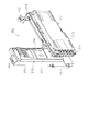
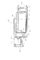
次に、第1制御基板ユニット201の構成を図13〜図16に基づいて説明する。図13は第1制御基板ユニット201の正面図、図14は同ユニット201の斜視図、図15は同ユニット201の分解斜視図、図16は同ユニット201を裏面から見た分解斜視図である。   Next, the configuration of the first control board unit 201 will be described based on FIGS. 13 to 16. 13 is a front view of the first control board unit 201, FIG. 14 is a perspective view of the unit 201, FIG. 15 is an exploded perspective view of the unit 201, and FIG. 16 is an exploded perspective view of the unit 201 viewed from the back. .

第1制御基板ユニット201は略L字状をなす取付台251を有し、取付台251に主制御装置271と音声ランプ制御装置272とが搭載されている。主制御装置271は、主たる制御を司るCPU、遊技プログラムを記憶したROM、遊技の進行に応じた必要なデータを記憶するRAM、各種機器との連絡をとるポート、各種抽選の際に用いられる乱数発生器、時間計数や同期を図る場合などに使用されるクロックパルス発生回路等を含む主基板を具備しており、主基板が透明樹脂材料等よりなる被包手段としての基板ボックス273に収容されて構成されている。なお、基板ボックス273は、略直方体形状のボックスベースと該ボックスベースの開口部を覆うボックスカバーとを備えている。これらボックスベースとボックスカバーとは封印手段としての封印ユニット274によって開封不能に連結され、これにより基板ボックス273が封印されている。   The first control board unit 201 has a substantially L-shaped mount 251 on which the main controller 271 and the voice lamp controller 272 are mounted. The main control device 271 is a CPU that controls the main control, a ROM that stores game programs, a RAM that stores necessary data according to the progress of a game, a port that communicates with various devices, and random numbers used in various lotterys. A main substrate including a generator, a clock pulse generating circuit used for time counting and synchronization, etc. is provided, and the main substrate is accommodated in a substrate box 273 as a covering means made of a transparent resin material or the like. Is configured. The substrate box 273 is provided with a substantially rectangular parallelepiped box base and a box cover that covers the opening of the box base. The box base and the box cover are unopenably connected by a sealing unit 274 as sealing means, whereby the substrate box 273 is sealed.

封印ユニット274はボックスベースとボックスカバーとを開封不能に連結する構成であれば任意の構成が適用できるが、ここでは図14等に示すように、5つの封印部材が連結された構成となっており、この封印部材の長孔に係止爪を挿入することでボックスベースとボックスカバーとが開封不能に連結されるようになっている。封印ユニット274による封印処理は、その封印後の不正な開封を防止し、また万一不正開封が行われてもそのような事態を早期に且つ容易に発見可能とするものであって、一旦開封した後でも再度封印処理を行うこと自体は可能である。すなわち、封印ユニット274を構成する5つの封印部材のうち、少なくとも一つの封印部材の長孔に係止爪を挿入することにより封印処理が行われる。そして、収容した主基板の不具合発生の際や主基板の検査の際など基板ボックス273を開封する場合には、係止爪が挿入された封印部材と他の封印部材との連結を切断する。その後、再度封印処理する場合は他の封印部材の長孔に係止爪を挿入する。基板ボックス273の開封を行った旨の履歴を当該基板ボックス273に残しておけば、基板ボックス273を見ることで不正な開封が行われた旨が容易に発見できる。   The sealing unit 274 can have any configuration as long as it can connect the box base and the box cover in an unopenable manner, but here, as shown in FIG. 14 etc., five sealing members are connected. The box base and the box cover are non-openably connected by inserting the locking claw into the elongated hole of the sealing member. The sealing process by the sealing unit 274 prevents unauthorized opening after the sealing, and makes it possible to detect such a situation early and easily even if unauthorized opening is performed, and the opening is temporarily performed. It is possible to perform the sealing process again even after the That is, the sealing process is performed by inserting the locking claw into the elongated hole of at least one of the five sealing members constituting the sealing unit 274. Then, when the substrate box 273 is unsealed, for example, at the time of failure occurrence of the main substrate housed or at the time of inspection of the main substrate, the connection between the sealing member in which the locking claw is inserted and the other sealing member is cut. Thereafter, when the sealing process is performed again, the locking claw is inserted into the long hole of the other sealing member. If a history indicating that the substrate box 273 has been opened is left in the substrate box 273, it is possible to easily find that the unauthorized opening has been performed by looking at the substrate box 273.

音声ランプ制御装置272は、例えば主制御装置271又は表示制御装置214からの指示に従い音声やランプ表示の制御を司るCPUや、その他ROM、RAM、各種ポート等を含む音声ランプ制御基板を具備しており、音声ランプ制御基板が透明樹脂材料等よりなる基板ボックス275に収容されて構成されている。音声ランプ制御装置272上には電源中継基板276が搭載されており、電源装置313の電源が電源中継基板276を介して表示制御装置214及び音声ランプ制御装置272に供給されるようになっている。   The audio lamp control device 272 comprises an audio lamp control board including a CPU for controlling the display of voice and lamp according to an instruction from the main control device 271 or the display control device 214, and other ROM, RAM, various ports, etc. The sound lamp control substrate is accommodated in a substrate box 275 made of a transparent resin material or the like. A power relay board 276 is mounted on the audio lamp controller 272, and the power of the power supply 313 is supplied to the display controller 214 and the audio lamp controller 272 via the power relay board 276. .

取付台251は、ポリカーボネート樹脂等の合成樹脂製であり、例えば緑や青等に着色されて不透明とされている。但し、取付台251は無色透明又は半透明であってもよい。取付台251の表面には平坦状をなす2つの基板搭載面252,253が設けられている。これら基板搭載面252,253は縦横に直交する向きに延び、前後方向に段差をもって形成されている。基板搭載面252の上縁部及び下縁部にはそれぞれ、基板搭載面252より起立した起立部254が一体成形されている。そして、横長の基板搭載面252上に主制御装置271が配置されると共に、縦長の基板搭載面253上に音声ランプ制御装置272が配置される。このとき、主制御装置271は、上下の側部が起立部254にて支えられる。また、音声ランプ制御装置172は、複数箇所でネジ等により基板搭載面253に固定される。   The mount 251 is made of synthetic resin such as polycarbonate resin, and is colored, for example, green or blue to be opaque. However, the mount 251 may be colorless and transparent or translucent. On the surface of the mount 251, two flat substrate mounting surfaces 252 and 253 are provided. The substrate mounting surfaces 252 and 253 extend in the direction perpendicular to the vertical and horizontal directions, and are formed with a step in the front-rear direction. At the upper edge and lower edge of the substrate mounting surface 252, erected portions 254 which are erected from the substrate mounting surface 252 are integrally formed. The main controller 271 is disposed on the horizontally long substrate mounting surface 252, and the audio lamp control device 272 is disposed on the vertically long substrate mounting surface 253. At this time, the upper and lower sides of the main control device 271 are supported by the rising portion 254. Further, the audio lamp control device 172 is fixed to the substrate mounting surface 253 by screws or the like at a plurality of places.

ここで、図15及び図16に示すように、基板搭載面252には、左右2カ所に横長形状の貫通孔256が形成されている。一方、主制御装置271の基板ボックス273には、その裏面の左右2カ所に回動操作式の固定具277が設けられている。主制御装置271を基板搭載面252に搭載する際には、基板搭載面252の貫通孔256に固定具277が挿通されるように主制御装置271を載置し、その状態で固定具277を回動操作することで主制御装置271がロックされる。従って、主制御装置271は第1制御基板ユニット201の裏面側から固定具277をロック解除しなければ取り外しできないため、基板取り外し等の不正行為に対して抑止効果が得られる。   Here, as shown in FIG. 15 and FIG. 16, horizontally long through holes 256 are formed on the left and right of the substrate mounting surface 252. On the other hand, in the substrate box 273 of the main control device 271, pivoting operation type fasteners 277 are provided at the left and right of the back surface. When the main control device 271 is mounted on the substrate mounting surface 252, the main control device 271 is placed so that the fixing tool 277 is inserted into the through hole 256 of the substrate mounting surface 252, and the fixing device 277 is The main control device 271 is locked by turning operation. Therefore, the main control device 271 can not be removed unless the fixing tool 277 is unlocked from the back surface side of the first control board unit 201, so that a deterrent effect against fraudulent acts such as removal of the board can be obtained.

また、取付台251において、主基板用の基板搭載面252の下方には、基板搭載面252の裏面空間に通じる開口を遮蔽するための遮蔽部257が設けられている。従って、基板搭載面252の下方より取付台251の裏面に手などを差し入れることが阻止され、固定具277のロック状態を不正に解除することができないようになっている。また、第1制御基板ユニット201をパチンコ機10裏面に搭載した状態では、当該ユニット201の上部が裏パックユニット203により覆われるため、やはり取付台251の裏面に手などを差し入れることが阻止され、固定具277のロック状態を不正に解除することができないようになっている。   Further, in the mounting table 251, a shielding portion 257 for shielding an opening communicating with the back surface space of the substrate mounting surface 252 is provided below the substrate mounting surface 252 for the main substrate. Therefore, the insertion of a hand or the like from the lower side of the substrate mounting surface 252 to the back surface of the mounting base 251 is prevented, and the locked state of the fixing tool 277 can not be released illegally. Further, in a state where the first control board unit 201 is mounted on the back surface of the pachinko machine 10, the upper part of the unit 201 is covered by the back pack unit 203, so that insertion of a hand or the like on the back surface of the mount 251 is also blocked. The locker 277 can not be unlocked illegally.

前述した通り、第1制御基板ユニット201は、裏パックユニット203を所定角度以上に大きく開いた状態又は同ユニット203を取り外した状態でなければ取り外すことが不可能であり、また、施錠装置を正しくキー操作して外枠11に対して本体枠12を開放しなければ、裏パックユニット203を開くことができない構成となっている。つまり、本体枠12を開くことができなければ、結果的に第1制御基板ユニット201を回動させたり取り外すことができず、ひいては主制御装置271の取り外しも不可能となる。それ故、主制御装置271の不正な載せ替えや盗難等を効果的に防止することができる。   As described above, the first control board unit 201 can not be removed unless the back pack unit 203 is largely opened to a predetermined angle or more or the unit 203 is removed, and the locking device can not be correctly removed. The back pack unit 203 can not be opened unless the main body frame 12 is opened with respect to the outer frame 11 by key operation. That is, if the main body frame 12 can not be opened, as a result, the first control board unit 201 can not be rotated or removed, and consequently the main control device 271 can not be removed. Therefore, unauthorized reassignment or theft of the main control device 271 can be effectively prevented.

主制御装置271は、パチンコ機10裏面から見て手前側に配置され、音声ランプ制御装置272はその奥側に配置される。この場合、基板搭載面252,253が前後方向に段差をもって形成されているため、これら基板搭載面252,253に主制御装置271及び音声ランプ制御装置272を搭載した状態において各制御装置271,272はその一部を前後に重ねて配置される。つまり、図14等にも見られるように、主制御装置271はその一部(本実施の形態では1/3程度)が浮いた状態で配置される。故に、主制御装置271に重なる領域まで音声ランプ制御装置272を拡張することが可能となり、また別の見方をすれば音声ランプ制御装置272に重なる領域まで主制御装置271を拡張することが可能となり、パチンコ機10という限られた大きさの中にあっても、各制御基板271,272の大型化に良好に対処できるとともに、各制御装置271,272を効率良く設置できる。また、第1制御基板ユニット201を遊技盤30に装着した状態では、基板搭載面252の後方にスペースが確保され、可変入賞装置32やその電気配線等が無理なく設置できるようになっている。なお、基板搭載面252の裏面には格子状のリブ258が設けられており、主制御装置271の支持強度が高められている。   The main control device 271 is disposed on the near side when viewed from the back of the pachinko machine 10, and the sound lamp control device 272 is disposed on the far side. In this case, since the board mounting surfaces 252, 253 are formed with a level difference in the front-rear direction, the main control device 271 and the audio lamp control device 272 are mounted on the substrate mounting surfaces 252, 253, respectively. Are placed one on top of the other. That is, as seen also in FIG. 14 and the like, the main control device 271 is disposed in a state where a part thereof (about 1/3 in the present embodiment) is floated. Therefore, the audio lamp control device 272 can be extended to an area overlapping the main control device 271. From another viewpoint, the main control device 271 can be extended to an area overlapping the audio lamp control device 272 Even in the limited size of the pachinko machine 10, it is possible to cope with the increase in size of the control boards 271 and 272, and to efficiently install the control devices 271 and 272. Further, in a state where the first control board unit 201 is mounted on the game board 30, a space is secured behind the board mounting surface 252, and the variable winning device 32 and its electrical wiring can be installed without difficulty. Note that grid-like ribs 258 are provided on the back surface of the substrate mounting surface 252, and the support strength of the main control device 271 is enhanced.

取付台251の左端面には上下一対の掛止ピン261が設けられており、この掛止ピン261を前記軸受け金具231に取り付けることで、第1制御基板ユニット201が遊技盤30に対して回動可能に片持ち支持される。取付台251の右端部には前記被締結孔232にはめ込まれる締結具として上下一対のナイラッチ262が設けられている。取付台251の上端部には前記係止爪片233が係止される長孔263が設けられている。従って、ナイラッチ262を被締結孔232にはめ込むと共に、長孔263に係止爪片233を係止させることで、第1制御基板ユニット201が遊技盤30に固定される。なお、軸受け金具231及び掛止ピン261が前記支軸部M1に、被締結孔232及びナイラッチ262が前記締結部M2に、係止爪片233及び長孔263が前記係止爪部M3に、それぞれ相当する。   A pair of upper and lower retaining pins 261 is provided on the left end surface of the mounting base 251, and by attaching the retaining pins 261 to the bearing fitting 231, the first control board unit 201 rotates relative to the game board 30. It is supported in a movable manner. A pair of upper and lower ny latches 262 are provided at the right end of the mounting base 251 as fasteners to be fitted into the to-be-fastened holes 232. At the upper end portion of the mounting base 251, an elongated hole 263 in which the locking claw piece 233 is locked is provided. Therefore, the first control board unit 201 is fixed to the gaming board 30 by inserting the ny latch 262 into the to-be-fastened hole 232 and locking the locking claw piece 233 to the long hole 263. The bearing fitting 231 and the locking pin 261 are in the support shaft portion M1, the to-be-fastened hole 232 and the ny latch 262 are in the fastening portion M2, and the locking claw piece 233 and the long hole 263 are in the locking claw portion M3. Each corresponds.

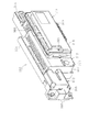
次に、第2制御基板ユニット202の構成を図17〜図19に基づいて説明する。図17は第2制御基板ユニット202の正面図、図18は同ユニット202の斜視図、図19は同ユニット202の分解斜視図である。   Next, the configuration of the second control board unit 202 will be described based on FIGS. 17 to 19. 17 is a front view of the second control board unit 202, FIG. 18 is a perspective view of the unit 202, and FIG. 19 is an exploded perspective view of the unit 202.

第2制御基板ユニット202は横長形状をなす取付台301を有し、取付台301に払出制御装置311、発射制御装置312、電源装置313及びカードユニット接続基板314が搭載されている。払出制御装置311及び発射制御装置312は制御の中枢をなすCPUや、その他ROM、RAM、各種ポート等を含む制御基板を具備している。払出制御装置311の払出制御基板により、賞品球や貸出球の払出が制御される。発射制御装置312の発射制御基板により、遊技者による遊技球発射ハンドル18の操作に従い発射モータ229の制御が行われる。また、電源装置313の電源基板により、各種制御装置等で要する所定の電源電圧が生成され出力される。カードユニット接続基板314は、パチンコ機前面の貸球操作部120及び図示しないカードユニットに電気的に接続され、主として遊技者による球貸し操作の指令を取り込んでそれを払出制御装置311に出力するものである。なお、カードユニットを介さずに球貸し装置等から上皿に遊技球が直接貸し出される現金機では、カードユニット接続基板314は不要である。   The second control board unit 202 has a mounting base 301 having a horizontally long shape, and the dispensing control device 311, the emission control device 312, the power supply device 313, and the card unit connection board 314 are mounted on the mounting base 301. The payout control device 311 and the emission control device 312 are provided with a control board including a CPU, which is central to control, ROM, RAM, various ports, and the like. The payout control board of the payout control device 311 controls the payout of the prize balls and the rental balls. The launch control board of the launch control device 312 controls the launch motor 229 in accordance with the operation of the game ball launch handle 18 by the player. Further, a predetermined power supply voltage required for various control devices and the like is generated and output by the power supply substrate of the power supply 313. The card unit connection board 314 is electrically connected to the ball operation unit 120 on the front of the pachinko machine and a card unit (not shown), and mainly takes in a ball lending operation command from the player and outputs it to the payout control device 311 It is. The card unit connection board 314 is not necessary for a cash machine in which gaming balls are directly lent out to the upper tray from a ball lending device or the like without passing through a card unit.

上記払出制御装置311、発射制御装置312、電源装置313及びカードユニット接続基板314は、透明樹脂材料等よりなる基板ボックス315,316,317,318にそれぞれ収容されて構成されている。特に、払出制御装置311では、主制御装置271と同様、被包手段を構成する基板ボックス315がボックスベースとボックスカバーとを備え、それらが封印手段としての封印ユニット319によって開封不能に連結され、これにより基板ボックス315が封印されている。払出制御装置311には状態復帰スイッチ321が設けられている。例えば、後述する払出モータの球詰まり等、払出エラーの発生時において状態復帰スイッチ321が押されると、払出モータが正逆回転され、球詰まりの解消(正常状態への復帰)が図られるようになっている。電源装置313にはRAM消去スイッチ323が設けられている。本パチンコ機10は各種データのバックアップ機能を有しており、万一停電が発生した際でも停電時の状態を保持し、停電からの復帰(復電)の際には停電時の状態に復帰できるようになっている。従って、例えば遊技ホールの営業終了の場合のように通常手順で電源を遮断すると遮断前の状態が記憶保持されるが、RAM消去スイッチ323を押しながら電源を投入すると、RAMデータが初期化されるようになっている。   The payout control device 311, the emission control device 312, the power supply device 313, and the card unit connection substrate 314 are respectively accommodated in substrate boxes 315, 316, 317, and 318 made of a transparent resin material or the like. In particular, in the dispensing control device 311, similarly to the main control device 27, the substrate box 315 constituting the packaging means comprises a box base and a box cover, and they are connected unopenably by the sealing unit 319 as sealing means, Thus, the substrate box 315 is sealed. The payout control device 311 is provided with a state recovery switch 321. For example, when the state recovery switch 321 is pressed at the occurrence of a dispensing error such as a ball clogging of a dispensing motor described later, the dispensing motor is rotated forward and reverse to eliminate the ball clogging (return to a normal state). It has become. The power supply device 313 is provided with a RAM erase switch 323. The pachinko machine 10 has a backup function of various data, and maintains the state at the time of a power failure even when a power failure occurs, and returns to the state at the time of a power failure when recovering from a power failure (power recovery) It can be done. Therefore, for example, when the power is shut off in the normal procedure as in the case of business closing of the game hall, the state before shutting off is stored and held, but when the power is turned on while pressing the RAM erase switch 323, the RAM data is initialized. It is supposed to be.

取付台301は例えば無色透明な樹脂成型品よりなり、その表面に平坦状をなす基板搭載面302が設けられている。基板搭載面302には、発射制御装置312、電源装置313及びカードユニット接続基板314が横並びとなった状態で搭載され、ネジ等で固定されている。電源装置313の基板ボックス317上には略平板状の台座プレート303が載置されるとともに台座プレート303上に払出制御装置311が搭載され、ネジ等で固定されている。払出制御装置311と電源装置313との間には台座プレート303が介在するため、例えばノイズ除去用の金属プレート等を設置するには台座プレート303に金属プレート等を取り付ければ良く、ノイズ対策が簡単に実現できる。   The mounting base 301 is made of, for example, a colorless and transparent resin molded product, and a flat substrate mounting surface 302 is provided on the surface thereof. The emission control device 312, the power supply device 313, and the card unit connection substrate 314 are mounted side by side on the substrate mounting surface 302 and fixed with screws or the like. A substantially flat pedestal plate 303 is mounted on the substrate box 317 of the power supply 313, and the payout control device 311 is mounted on the pedestal plate 303 and fixed by screws or the like. Since the pedestal plate 303 intervenes between the payout control device 311 and the power supply 313, for example, in order to install a metal plate for noise removal or the like, it is sufficient to attach the metal plate or the like to the pedestal plate 303. Can be realized.

取付台301には、パチンコ機10後方からみて右端部に上下一対の掛止ピン305が設けられており、掛止ピン305を前記軸受け部237に上方から挿通させることで、第2制御基板ユニット202が本体枠12に対して回動可能に片持ち支持される。取付台301の左端部には締結具として上下一対のナイラッチ306が設けられており、ナイラッチ306を前記被締結孔239にはめ込むことで、第2制御基板ユニット202が本体枠12に固定される。なお、軸受け部237及び掛止ピン305が前記支軸部M4に、被締結孔239及びナイラッチ306が前記締結部M5に、それぞれ相当する。   The mounting base 301 is provided with a pair of upper and lower retaining pins 305 at the right end when viewed from the rear of the pachinko machine 10, and the second control board unit is inserted by inserting the retaining pin 305 into the bearing portion 237 from above. A single-piece 202 is rotatably supported on the main body frame 12. A pair of upper and lower ny latches 306 are provided at the left end of the mounting base 301 as fasteners, and the second control board unit 202 is fixed to the main body frame 12 by inserting the ny latch 306 into the to-be-fastened hole 239. The bearing portion 237 and the retaining pin 305 correspond to the support shaft portion M4, and the to-be-fastened hole 239 and the ny latch 306 correspond to the fastening portion M5.

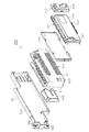
次に、裏パックユニット203の構成を図20〜図22に基づいて説明する。図20は裏パックユニット203の正面図、図21は裏パックユニット203の分解斜視図である。図22はタンクレールの分解斜視図である。   Next, the configuration of the back pack unit 203 will be described based on FIGS. FIG. 20 is a front view of the back pack unit 203, and FIG. 21 is an exploded perspective view of the back pack unit 203. FIG. 22 is an exploded perspective view of the tank rail.

裏パックユニット203は、裏パック351と遊技球の払出機構部352とが一体化されることにより構成されている。裏パック351は例えばABS樹脂等の合成樹脂により一体成型されており、略平坦状のベース部353と、パチンコ機10後方に突出し横長の略直方体形状をなす保護カバー部354とを有する。保護カバー部354は左右側面及び上面が閉鎖され且つ下面のみが開放された形状をなし、少なくとも可変表示ユニット35を囲むのに十分な大きさを有する。但し、本実施の形態では、前述の音声ランプ制御装置272も併せて囲む構成となっている。保護カバー部354の背面には多数の通気孔354aが設けられている。通気孔354aは各々が長孔状をなし、それぞれの通気孔354aが比較的近い位置で隣り合うよう設けられている。従って、隣り合う通気孔354a間にある樹脂部分を切断することにより、裏パック351の背面を容易に開口させることができる。つまり、通気孔354a間の樹脂部分を切断してその内部の表示制御装置214等を露出させることで、所定の検定等を容易に実施することができるようになっている。   The back pack unit 203 is configured by integrating the back pack 351 and the payout mechanism portion 352 of the game ball. The back pack 351 is integrally molded of, for example, a synthetic resin such as ABS resin, and has a substantially flat base portion 353 and a protection cover portion 354 which protrudes to the rear of the pachinko machine 10 and has a horizontally long substantially rectangular parallelepiped shape. The protective cover portion 354 has a shape in which the left and right side surfaces and the upper surface are closed and only the lower surface is open, and at least has a size sufficient to surround the variable display unit 35. However, in the present embodiment, the above-mentioned sound lamp control device 272 is also surrounded. A large number of vent holes 354 a are provided on the back surface of the protective cover portion 354. The vent holes 354a are each in the shape of a long hole, and the vent holes 354a are provided adjacent to each other at a relatively close position. Therefore, the back surface of the back pack 351 can be easily opened by cutting the resin portion between the adjacent air holes 354a. That is, by cutting the resin portion between the vent holes 354a to expose the display control device 214 and the like inside, it is possible to easily carry out a predetermined test or the like.

裏パック351のベース部353には、保護カバー部354を迂回するようにして払出機構部352が配設されている。すなわち、裏パック351の最上部には上方に開口したタンク355が設けられており、タンク355には遊技ホールの島設備から供給される遊技球が逐次補給される。タンク355の下方には、例えば横方向2列(2条)の球通路を有し下流側に向けて緩やかに傾斜するタンクレール356が連結され、タンクレール356の下流側には上下方向に延びるケースレール357が連結されている。払出装置358はケースレール357の最下流部に設けられ、払出制御装置311の制御により払出モータ358aが駆動されて必要個数の遊技球の払出が適宜行われる。払出装置358より払い出された遊技球は払出通路359等を通じて前記上皿23等に供給される。なお、図示は省略するが、ケースレール357の上流部には、タンク355やタンクレール356から供給される遊技球の有無を検出するタンク球無しセンサが設けられている。また、払出装置358には、払出モータ358aの回転を検出する払出回転センサと、払い出される遊技球数をカウントする払出カウントスイッチとが設けられている。   A dispensing mechanism portion 352 is disposed on the base portion 353 of the back pack 351 so as to bypass the protective cover portion 354. That is, a tank 355 opened upward is provided at the top of the back pack 351, and gaming balls supplied from an island facility of the game hall are successively supplied to the tank 355. Below the tank 355, there is connected a tank rail 356 which has, for example, two rows (two rows) of ball passages in the lateral direction and which slopes gently toward the downstream side, and extends vertically on the downstream side of the tank rail 356. Case rails 357 are connected. The payout device 358 is provided at the most downstream part of the case rail 357, and the payout motor 358a is driven by the control of the payout control device 311, and the necessary number of gaming balls are paid out appropriately. The game balls paid out from the payout device 358 are supplied to the upper tray 23 and the like through the payout passage 359 and the like. Although not shown, a tank ball absence sensor for detecting the presence or absence of a game ball supplied from the tank 355 or the tank rail 356 is provided on the upstream side of the case rail 357. Further, the payout device 358 is provided with a payout rotation sensor that detects the rotation of the payout motor 358a and a payout count switch that counts the number of gaming balls to be paid out.

タンクレール356には、当該タンクレール356に振動を付加するためのバイブレータ360が取り付けられている。バイブレータ360は、バイブモータとそのバイブモータを収容する合成樹脂製のケースとによりユニット化されており、2本の脚部360aでタンクレール356に取り付けられている。従って、仮にタンクレール356付近で球詰まりが生じた際、バイブレータ360が駆動されることで球詰まりが解消されるようになっている。   A vibrator 360 for attaching a vibration to the tank rail 356 is attached to the tank rail 356. The vibrator 360 is unitized by a vibration motor and a synthetic resin case accommodating the vibration motor, and is attached to the tank rail 356 by two legs 360a. Therefore, if a ball jam occurs around the tank rail 356, the ball jam is eliminated by driving the vibrator 360.

タンクレール356の構成ついて詳述すると、図22に示すように、タンクレール356は上方に開口した長尺樋状をなすレール本体361を有している。レール本体361の上流部には球面状の球受部362が形成され、球受部362によりタンク355より落下してきた遊技球が円滑にレール本体361内に取り込まれるようになっている。レール本体361には長手方向に延びる仕切壁363が設けられており、仕切壁363により遊技球が二手に分流されるようになっている。仕切壁363により仕切られた2条の球通路は遊技球の直径よりも僅かに幅広となっている。仕切壁363により仕切られた各球通路の底面には、1筋又は2筋の突条364が設けられると共に、その突条364の側方に塵埃を落下させるための開口部365が設けられている。レール本体361には、その下流側半分程度の天井部分を覆うようにして整流板367が配設されている。整流板367は、下流側ほどタンクレール356内の球通路高さを制限するよう弓なりに反った形状をしており、その下面には長手方向に延びる凸部368が形成されている。これにより、タンクレール356内を流れる各遊技球は最終的には上下に積み重なることなく下流側に流出する。従って、タンクレール356に多量の遊技球が流れ込んできても、遊技球の噛み込みが防止され、タンクレール356内における球詰まりが発生し難くなっている。なお、レール本体361が帯電防止のために黒色の導電性ポリカーボネート樹脂により成形されるのに対し、整流板367は球詰まり等を目視で確認できるように透明のポリカーボネート樹脂により成形されている。整流板367は着脱可能に設けられており、当該整流板367を取り外すことによりタンクレール356内のメンテナンスが容易に実施できるようになっている。整流板367には、遊技球の流下を阻止するための手動式のストッパ369が取り付けられている。   More specifically, as shown in FIG. 22, the tank rail 356 has a long rod-like rail main body 361 opened upward. A spherical ball receiving portion 362 is formed on the upstream portion of the rail main body 361, and the game ball dropped from the tank 355 is smoothly taken into the rail main body 361 by the ball receiving portion 362. The rail main body 361 is provided with a partition wall 363 extending in the longitudinal direction, and the gaming wall is divided by the partition wall 363 into two hands. The two ball passages divided by the partition wall 363 are slightly wider than the diameter of the gaming ball. At the bottom of each ball passage partitioned by the partition wall 363, one or two ridges 364 are provided, and an opening 365 for dropping dust on the side of the ridge 364 is provided. There is. A straightening vane 367 is disposed on the rail main body 361 so as to cover a ceiling part on the downstream half side. The straightening vane 367 has a bowed shape so as to limit the height of the ball passage in the tank rail 356 toward the downstream side, and a convex portion 368 extending in the longitudinal direction is formed on the lower surface thereof. As a result, the gaming balls flowing in the tank rail 356 finally flow out downstream without being stacked up and down. Therefore, even if a large amount of gaming balls flow into the tank rail 356, biting of the gaming balls is prevented, and ball clogging in the tank rail 356 is less likely to occur. The rail main body 361 is molded of a black conductive polycarbonate resin to prevent electrification, while the flow regulating plate 367 is molded of a transparent polycarbonate resin so that ball clogging and the like can be visually confirmed. The straightening vane 367 is detachably provided, and by removing the straightening vane 367, maintenance in the tank rail 356 can be easily performed. A manual stopper 369 for preventing the flow of the game ball is attached to the current plate 367.

図20,図21の説明に戻り、払出機構部352には、払出制御装置311から払出装置358への払出指令の信号を中継する払出中継基板381が設置されると共に、外部より主電源を取り込むための電源スイッチ基板382が設置されている。電源スイッチ基板382には、電圧変換器を介して例えば交流24ボルトの主電源が供給され、電源スイッチ382aの切替操作により電源ON又は電源OFFとされるようになっている。   Referring back to FIG. 20 and FIG. 21, the payout mechanism board 352 is provided with a payout relay board 381 for relaying the signal of the payout command from the payout control device 311 to the payout device 358, and takes in the main power from the outside A power switch substrate 382 is installed. The power switch substrate 382 is supplied with a main power of, for example, 24 AC, via a voltage converter, and is turned on or off by switching the power switch 382a.

タンク355から払出通路359に至るまでの払出機構部352は何れも導電性を有する合成樹脂材料、例えば導電性ポリカーボネート樹脂にて成形され、その一部にてアースされている。これにより、遊技球の帯電によるノイズの発生が抑制されるようになっている。   The dispensing mechanism portion 352 from the tank 355 to the dispensing passage 359 is formed of a conductive synthetic resin material, for example, a conductive polycarbonate resin, and is partially grounded. Thereby, generation of noise due to charging of the gaming ball is suppressed.

裏パック351には、その右上部に枠用外部端子板390が設けられている。枠用外部端子板390には、タンク355やタンクレール356で遊技球が不足した場合に信号出力するための出力端子、所定個数の賞球を払い出す毎に信号出力するための出力端子、所定個数の遊技球を貸し出す毎に信号出力するための出力端子、本体枠12の開放時に信号出力するための出力端子、及び前扉枠13の開放時に信号出力するための出力端子が設けられている。そして、これらの出力端子を通じて、遊技ホール側の管理制御装置に対して枠側の状態に関する信号が出力される。なお、所定個数の遊技球を貸し出す毎に信号出力するための出力端子はいわゆる現金機においては不要である。   The back pack 351 is provided with a frame external terminal board 390 at the upper right portion thereof. The frame external terminal board 390 has an output terminal for outputting a signal when a game ball runs out in the tank 355 or the tank rail 356, an output terminal for outputting a signal each time a predetermined number of award balls are paid out, and a predetermined There are provided an output terminal for outputting a signal each time a game ball is lent out, an output terminal for outputting a signal when the main body frame 12 is opened, and an output terminal for outputting a signal when the front door frame 13 is opened. . Then, through these output terminals, a signal regarding the state of the frame side is output to the management control device on the game hall side. In addition, an output terminal for outputting a signal each time a predetermined number of gaming balls are lent is unnecessary in a so-called cash machine.

裏パック351には、枠用外部端子板390に隣接して略四角形状の窓部391が設けられている。従って、裏パックユニット103を本体枠12に取り付けた状態では、窓部391を通じて遊技盤30裏面の盤用外部端子板230が露出し、裏パックユニット103を装着したままで盤用外部端子板230の操作を行うことができるようになっている。前述のとおり、盤用外部端子板230は取り外し容易な状態で集合板ユニット215に取り付けられていることから、盤用外部端子板230の配線を接続したままで、窓部391を介して当該盤用外部端子板230を取り出すことも可能となる。裏パック351の右上部には本体枠12の開放の状態を検出するための本体枠開放スイッチ392が設けられており、外枠11に対して本体枠12を閉じた状態では当該スイッチ392の金属接点が閉じて本体枠12の閉鎖が検知され、外枠11に対して本体枠12を開いた状態では金属接点が開いて本体枠12の開放が検知されるようになっている。   The back pack 351 is provided with a substantially square window portion 391 adjacent to the frame external terminal plate 390. Therefore, when the back pack unit 103 is attached to the main body frame 12, the board external terminal board 230 on the back of the game board 30 is exposed through the window 391 and the board external terminal board 230 is mounted with the back pack unit 103 attached. It is possible to do the operation of. As described above, since the panel external terminal board 230 is attached to the collective plate unit 215 in an easily removable state, while the wiring of the panel external terminal board 230 is connected, the panel via the window 391 It is also possible to take out the external terminal board 230. A main body frame open switch 392 for detecting the open state of the main body frame 12 is provided at the upper right portion of the back pack 351, and the metal of the switch 392 is closed when the main body frame 12 is closed with respect to the outer frame 11. The contacts are closed and the closing of the body frame 12 is detected, and in the state where the body frame 12 is opened with respect to the outer frame 11, the metal contacts are opened and the opening of the body frame 12 is detected.

裏パック351には、パチンコ機10後方からみて右端部に上下一対の掛止ピン385が設けられており、掛止ピン385を前記軸受け部238に上方から挿通させることで、裏パックユニット203が本体枠12に対して回動可能に片持ち支持される。裏パック351には、左端部に締結具として上下一対のナイラッチ386が設けられると共に、上端部に係止孔387が設けられており、ナイラッチ386を前記被締結孔240にはめ込むと共に、係止孔387に前記固定具242を挿入した上で当該固定具242を回動操作することで、裏パックユニット203が本体枠12に固定される。また、前記固定具241,243によっても裏パックユニット203が本体枠12に固定される。なお、軸受け部238及び掛止ピン385が前記支軸部M6に、被締結孔240及びナイラッチ386が前記締結部M7に、固定具242及び係止孔387が前記係止部M8に、それぞれ相当する。また、固定具243が前記係止部M9に相当する。   The back pack 351 is provided with a pair of upper and lower retaining pins 385 at the right end when viewed from the rear of the pachinko machine 10, and by inserting the retaining pins 385 into the bearing portion 238 from above, the back pack unit 203 The main body frame 12 is pivotably supported in a cantilever manner. The back pack 351 is provided with a pair of upper and lower ny latches 386 as fasteners at the left end and a locking hole 387 at the upper end, and the ny latch 386 is fitted into the to-be-fastened hole 240 and the locking hole The back pack unit 203 is fixed to the main body frame 12 by rotating the fixing tool 242 after inserting the fixing tool 242 into 387. The back pack unit 203 is also fixed to the main body frame 12 by the fixing devices 241 and 243. The bearing portion 238 and the locking pin 385 correspond to the shaft portion M6, the to-be-fastened hole 240 and the ny latch 386 to the fastening portion M7, and the fixing tool 242 and the locking hole 387 to the locking portion M8. Do. Further, the fixing tool 243 corresponds to the locking portion M9.

次に、本パチンコ機10の電気的構成について、図23のブロック図に基づいて説明する。   Next, the electrical configuration of the pachinko machine 10 will be described based on the block diagram of FIG.

主制御装置271には、演算装置である1チップマイコンとしてのCPU501が搭載されている。CPU501には、該CPU501により実行される各種の制御プログラムや固定値データを記憶したROM502と、そのROM502内に記憶される制御プログラムの実行に際して各種のデータ等を一時的に記憶するためのメモリであるRAM503と、割込回路やタイマ回路、データ送受信回路などの各種回路が内蔵されている。   The main controller 271 is equipped with a CPU 501 as a one-chip microcomputer which is an arithmetic device. The CPU 501 is a ROM 502 storing various control programs to be executed by the CPU 501 and fixed value data, and a memory for temporarily storing various data etc. when the control program stored in the ROM 502 is executed. A certain RAM 503 and various circuits such as an interrupt circuit, a timer circuit, and a data transmission / reception circuit are incorporated.

RAM503は、パチンコ機10の電源の遮断後においても電源装置313からバックアップ電圧が供給されてデータを保持(バックアップ)できる構成となっており、RAM503には、各種のデータ等を一時的に記憶するためのメモリやエリアの他に、バックアップエリア503aが設けられている。   The RAM 503 is configured to be able to receive data (backup) supplied with a backup voltage from the power supply 313 even after the pachinko machine 10 is powered off, and temporarily stores various data in the RAM 503. A backup area 503a is provided in addition to the memory and the area for the purpose.

バックアップエリア503aは、停電などの発生により電源が遮断された場合において、電源遮断時(停電発生時を含む。以下同様)のスタックポインタや、各レジスタ、I/O等の値を記憶しておくためのエリアであり、電源投入時(停電解消による電源投入を含む。以下同様)には、バックアップエリア503aの情報に基づいてパチンコ機10の状態が電源遮断前の状態に復帰できるようになっている。バックアップエリア503aへの書き込みはNMI割込み処理(図37参照)によって電源遮断時に実行され、バックアップエリア503aに書き込まれた各値の復帰は電源投入時のメイン処理(図26参照)において実行される。なお、CPU501のNMI端子(ノンマスカブル割込端子)には、停電等の発生による電源遮断時に、停電監視回路542からの停電信号SG1が入力されるように構成されており、停電の発生により停電時処理としてのNMI割込み処理が即座に実行される。   The backup area 503a stores the values of the stack pointer, the respective registers, the I / O, etc. when the power is shut off (including the time of the power outage, the same applies hereinafter) when the power is shut off due to the occurrence of a power outage or the like. The area of the pachinko machine 10 can be restored to the state before the power cut off based on the information of the backup area 503a when the power is turned on (including the power on by the power failure cancellation. The same applies hereinafter). There is. Writing to the backup area 503a is executed when the power is shut off by NMI interrupt processing (see FIG. 37), and restoration of each value written to the backup area 503a is executed in the main processing (see FIG. 26) when the power is turned on. The power failure signal SG1 from the power failure monitoring circuit 542 is input to the NMI terminal (non-maskable interrupt terminal) of the CPU 501 at the time of power interruption due to the occurrence of a power failure or the like. NMI interrupt processing as processing is immediately executed.

主制御装置271のCPU501には、アドレスバス及びデータバスで構成されるバスライン504を介して入出力ポート505が接続されている。主制御装置271の入力側には、後述するRAM消去スイッチ回路543、払出制御装置311や、その他図示しないスイッチ群などが接続されている。一方、主制御装置271の出力側には、払出制御装置311や表示制御装置214、各可変入賞装置32a,32bの大入賞口ソレノイド等が接続されている。また、第1特定ランプ部47に配設されたLEDランプのスイッチや第2特定ランプ部48に配設されたLEDランプのスイッチも接続されている。これにより、第1特定ランプ部47及び第2特定ランプ部48は、主制御装置271により直接的に制御されることとなる。   An input / output port 505 is connected to the CPU 501 of the main control device 271 via a bus line 504 configured by an address bus and a data bus. The input side of the main control device 271 is connected to a RAM erase switch circuit 543, a payout control device 311, and other switches not shown. On the other hand, on the output side of the main control device 271, a payout control device 311, a display control device 214, a winning prize opening solenoid of each of the variable winning devices 32a and 32b, and the like are connected. Further, a switch of an LED lamp disposed in the first specific lamp unit 47 and a switch of an LED lamp disposed in the second specific lamp unit 48 are also connected. As a result, the first specified lamp unit 47 and the second specified lamp unit 48 are directly controlled by the main control device 271.

払出制御装置311は、払出モータ358aにより賞球や貸し球の払出制御を行うものである。演算装置であるCPU511は、そのCPU511により実行される制御プログラムや固定値データ等を記憶したROM512と、ワークメモリ等として使用されるRAM513とを備えている。   The payout control device 311 performs payout control of the winning balls and the rental balls by the payout motor 358a. The CPU 511, which is an arithmetic device, includes a ROM 512 storing a control program to be executed by the CPU 511, fixed value data, and the like, and a RAM 513 used as a work memory or the like.

払出制御装置311のRAM513は、主制御装置271のRAM503と同様に、パチンコ機10の電源の遮断後においても電源装置313からバックアップ電圧が供給されてデータを保持(バックアップ)できる構成となっており、RAM513には、各種のデータ等を一時的に記憶するためのメモリやエリアの他に、バックアップエリア513aが設けられている。   Similar to the RAM 503 of the main control device 271, the RAM 513 of the payout control device 311 is configured to be able to receive (back up) data by being supplied with a backup voltage from the power supply device 313 even after the pachinko machine 10 is powered off. The RAM 513 is provided with a backup area 513 a in addition to a memory and an area for temporarily storing various data and the like.

バックアップエリア513aは、停電などの発生により電源が遮断された場合において、電源遮断時のスタックポインタや、各レジスタ、I/O等の値を記憶しておくためのエリアであり、電源投入時には、このバックアップエリア513aの情報に基づいてパチンコ機10の状態が電源遮断前の状態に復帰できるようになっている。バックアップエリア513aへの書き込みはNMI割込み処理によって電源遮断時に実行され、バックアップエリア513aに書き込まれた各値の復帰は電源投入時のメイン処理において実行される。なお、主制御装置271のCPU501と同様、CPU511のNMI端子にも、停電等の発生による電源遮断時に停電監視回路542から停電信号SG1が入力されるように構成されており、停電の発生により、NMI割込み処理が即座に実行されるようになっている。   The backup area 513a is an area for storing values such as a stack pointer at the time of power shutdown, each register, and I / O when the power is shut down due to the occurrence of a power failure or the like. Based on the information of the backup area 513a, the state of the pachinko machine 10 can be restored to the state before the power is turned off. Writing to the backup area 513a is executed when the power is shut off by NMI interrupt processing, and restoration of each value written to the backup area 513a is executed in the main processing when the power is turned on. Similar to the CPU 501 of the main control device 271, the NMI terminal of the CPU 511 is configured to receive the power failure signal SG1 from the power failure monitoring circuit 542 at the time of power interruption due to the occurrence of power failure etc. NMI interrupt processing is to be executed immediately.

払出制御装置311のCPU511には、アドレスバス及びデータバスで構成されるバスライン514を介して入出力ポート515が接続されている。入出力ポート515には、RAM消去スイッチ回路543、主制御装置271、発射制御装置312、払出モータ358aなどがそれぞれ接続されている。   An input / output port 515 is connected to the CPU 511 of the payout control device 311 via a bus line 514 configured by an address bus and a data bus. To the input / output port 515, a RAM erase switch circuit 543, a main controller 271, a launch controller 312, a payout motor 358a, etc. are connected.

発射制御装置312は、発射モータ229による遊技球の発射を許可又は禁止するものであり、発射モータ229は、所定条件が整っている場合に駆動が許可される。具体的には、払出制御装置311から発射許可信号が出力されていること、遊技者が遊技球発射ハンドル18に触れていることをセンサ信号により検出していること、発射を停止させるための発射停止スイッチが操作されていないことを条件に、発射モータ229が駆動され、遊技球発射ハンドル18の操作量に応じた強さで遊技球が発射される。   The launch control device 312 permits or prohibits the launch of the gaming ball by the launch motor 229. The launch motor 229 is permitted to drive when the predetermined condition is satisfied. Specifically, a release permission signal is output from the payout control device 311, a sensor signal is detected by the player touching the game ball release handle 18, a release for stopping the release On the condition that the stop switch is not operated, the firing motor 229 is driven, and the gaming ball is fired with a strength according to the amount of operation of the gaming ball firing handle 18.

表示制御装置214は、図柄表示装置41における第1図柄(特別図柄)の変動表示を制御するものである。表示制御装置214は、CPU521と、ROM(プログラムROM)522と、ワークRAM523と、ビデオRAM524と、キャラクタROM525と、画像コントローラ526と、入力ポート527と、2つの出力ポート528,529と、バスライン530,531とを備えている。入力ポート527の入力側には主制御装置271の出力側が接続され、入力ポート527の出力側には、CPU521、ROM522、ワークRAM523、画像コントローラ526が接続されると共にバスライン530を介して出力ポート528が接続されている。出力ポート528の出力側には音声ランプ制御装置272が接続されている。また、画像コントローラ526にはバスライン531を介して出力ポート529が接続されており、その出力ポート529の出力側には図柄表示装置41が接続されている。   The display control device 214 controls the variable display of the first symbol (special symbol) in the symbol display device 41. The display control device 214 includes a CPU 521, a ROM (program ROM) 522, a work RAM 523, a video RAM 524, a character ROM 525, an image controller 526, an input port 527, two output ports 528 and 529, and a bus line. 530 and 531 are provided. The output side of the main controller 271 is connected to the input side of the input port 527, and the CPU 521, the ROM 522, the work RAM 523 and the image controller 526 are connected to the output side of the input port 527 and the output port via the bus line 530 528 is connected. An audio lamp control device 272 is connected to the output side of the output port 528. Further, an output port 529 is connected to the image controller 526 via a bus line 531, and a symbol display device 41 is connected to the output side of the output port 529.

表示制御装置214のCPU521は、主制御装置271から送信される図柄表示コマンドに基づいて図柄表示装置41の表示を制御する。ROM522は、CPU521により実行される各種の制御プログラムや固定値データを記憶するためのメモリであり、ワークRAM523は、CPU521による各種プログラムの実行時に使用されるワークデータやフラグを一時的に記憶するためのメモリである。   The CPU 521 of the display control device 214 controls the display of the symbol display device 41 based on the symbol display command transmitted from the main control device 271. The ROM 522 is a memory for storing various control programs to be executed by the CPU 521 and fixed value data. The work RAM 523 is for temporarily storing work data and flags used when the CPU 521 executes various programs. Memory.

ビデオRAM524は、図柄表示装置41に表示される表示データを記憶するためのメモリであり、ビデオRAM524の内容を書き替えることにより、図柄表示装置41の表示内容が変更される。キャラクタROM525は、図柄表示装置41に表示される図柄などのキャラクタデータを記憶するためのメモリである。画像コントローラ526は、CPU521、ビデオRAM524、出力ポート529のそれぞれのタイミングを調整してデータの読み書きに介在すると共に、ビデオRAM524に記憶される表示データを、キャラクタROM525から所定のタイミングで読み出して図柄表示装置41に表示させるものである。   The video RAM 524 is a memory for storing display data displayed on the symbol display device 41, and the display content of the symbol display device 41 is changed by rewriting the content of the video RAM 524. The character ROM 525 is a memory for storing character data such as a symbol displayed on the symbol display device 41. The image controller 526 adjusts the respective timings of the CPU 521, the video RAM 524, and the output port 529 to intervene in reading and writing of data, and reads the display data stored in the video RAM 524 from the character ROM 525 at a predetermined timing to display symbols. It is displayed on the device 41.

電源装置313は、パチンコ機10の各部に電源を供給するための電源部541と、停電等による電源遮断を監視する停電監視回路542と、RAM消去スイッチ323に接続されてなるRAM消去スイッチ回路543とを備えている。電源部541は、図示しない電源経路を通じて、主制御装置271や払出制御装置311等に対して各々に必要な動作電源を供給する。その概要としては、電源部541は、外部より供給される交流24ボルト電源を取り込み、各種スイッチやモータ等を駆動するための+12V電源、ロジック用の+5V電源、RAMバックアップ用のバックアップ電源などを生成し、これら+12V電源、+5V電源及びバックアップ電源を主制御装置271や払出制御装置311等に対して供給する。なお、発射制御装置312に対しては払出制御装置311を介して動作電源(+12V電源、+5V電源等)が供給される。   The power supply 313 includes a power supply 541 for supplying power to each part of the pachinko machine 10, a power failure monitoring circuit 542 for monitoring power interruption due to a power failure, etc., and a RAM erase switch circuit 543 connected to the RAM erase switch 323. And have. The power supply unit 541 supplies necessary operation power to each of the main control device 271 and the payout control device 311 through a power supply path (not shown). As a summary, the power supply unit 541 takes in AC 24 volt power supplied from the outside, and generates +12 V power for driving various switches, motors, etc., +5 V power for logic, backup power for RAM backup, etc. Then, the +12 V power supply, the +5 V power supply and the backup power supply are supplied to the main control device 271 and the payout control device 311 and the like. An operation power supply (+12 V power supply, +5 V power supply, etc.) is supplied to the emission control device 312 via the payout control device 311.

停電監視回路542は、停電等の発生による電源遮断時に、主制御装置271のCPU501及び払出制御装置311のCPU511の各NMI端子へ停電信号SG1を出力するための回路である。停電監視回路542は、電源部541から出力される最大電圧である直流安定24ボルトの電圧を監視し、この電圧が22ボルト未満になった場合に停電(電源遮断)の発生と判断して、停電信号SG1を主制御装置271及び払出制御装置311へ出力する。停電信号SG1の出力によって、主制御装置271及び払出制御装置311は、停電の発生を認識し、NMI割込み処理を実行する。なお、電源部541は、直流安定24ボルトの電圧が22ボルト未満になった後においても、NMI割込み処理の実行に充分な時間の間、制御系の駆動電圧である5ボルトの出力を正常値に維持するように構成されている。よって、主制御装置271及び払出制御装置311は、NMI割込み処理を正常に実行し完了することができる。   The power failure monitoring circuit 542 is a circuit for outputting the power failure signal SG1 to each NMI terminal of the CPU 501 of the main control device 271 and the CPU 511 of the payout control device 311 at the time of power interruption due to the occurrence of power failure. The power failure monitoring circuit 542 monitors the voltage of the stable DC voltage of 24 volts which is the maximum voltage output from the power supply 541, and determines that a power failure (power interruption) occurs when this voltage becomes less than 22 volts, The power failure signal SG1 is output to the main control device 271 and the payout control device 311. Based on the output of the power failure signal SG1, the main controller 271 and the payout control device 311 recognize the occurrence of the power failure and execute NMI interrupt processing. The power supply unit 541 outputs an output voltage of 5 volts, which is a drive voltage of the control system, as a normal value for a time sufficient for execution of the NMI interrupt processing even after the voltage of the DC stable 24 volts becomes less than 22 volts. It is configured to maintain. Thus, the main control device 271 and the payout control device 311 can execute and complete the NMI interrupt processing normally.

RAM消去スイッチ回路543は、RAM消去スイッチ323のスイッチ信号を取り込み、そのスイッチ323の状態に応じて主制御装置271及び払出制御装置311のバックアップデータをクリアするためのRAM消去信号SG2を出力する回路である。RAM消去スイッチ323が押された際、RAM消去スイッチ回路543は、主制御装置271及び払出制御装置311に対してRAM消去信号SG2を出力する。これにより、RAM消去スイッチ323が押された状態でパチンコ機10の電源が投入されると、主制御装置271及び払出制御装置311においてそれぞれのバックアップエリア503a,513aのデータがクリアされる。   The RAM erase switch circuit 543 takes in a switch signal of the RAM erase switch 323 and outputs a RAM erase signal SG2 for clearing the backup data of the main controller 271 and the payout control device 311 according to the state of the switch 323. It is. When the RAM erase switch 323 is pressed, the RAM erase switch circuit 543 outputs a RAM erase signal SG2 to the main control device 271 and the payout control device 311. Thus, when the power of the pachinko machine 10 is turned on while the RAM erase switch 323 is pressed, the data in the backup areas 503a and 513a of the main control device 271 and the payout control device 311 are cleared.

ここで、図柄表示装置41の表示内容について、図24に基づいて説明する。   Here, the display contents of the symbol display device 41 will be described based on FIG.

図柄表示装置には、左・中・右の3つの図柄列が設定されている。各図柄列は、例えば「0」〜「9」の数字を各々付した主図柄と、例えば菱形状の絵図柄からなる副図柄とにより構成されている。各主図柄及び副図柄がそれぞれ第1図柄を構成している。各図柄列では、数字の昇順又は降順に主図柄が配列されると共に各主図柄の間に副図柄が配されている。すなわち、各図柄列には、10個の主図柄及び10個の副図柄の計20個の第1図柄が備えられている。この場合において、「0」,「1」,「3」,「5」,「7」,「8」,「9」の数字が付された主図柄は「高確率図柄」に相当し、当該高確率図柄で大当たりが発生した場合、遊技状態が大当たり状態に移行すると共に、さらにその後、特典遊技状態としての高確率状態に移行する。また、「2」,「4」,「6」の数字が付された主図柄は「低確率図柄」に相当し、当該低確率図柄で大当たりが発生した場合、大当たり状態には移行するものの、大当たり状態終了後は高確率状態に移行することなく通常状態に移行する。なお、高確率状態とは、大当たり状態の終了後に付加価値としてその後の大当たり確率がアップした状態、いわゆる確変状態のことをいい、通常状態(低確率状態)とはそのような高確率状態でない遊技状態をいう。また、第1特定ランプ部47においては、大当たり状態終了後に高確率状態に移行する確変大当たりの場合に赤色が表示され、大当たり状態終了後に通常状態に移行する通常大当たりの場合に緑色が表示される。   In the symbol display device, three symbol rows of left, middle and right are set. Each symbol row is composed of, for example, a main symbol to which numerals "0" to "9" are respectively attached, and a sub-symbol consisting of, for example, a rhombus-shaped symbol. Each main symbol and the sub symbol constitute the first symbol. In each symbol row, the main symbols are arranged in ascending or descending order of the numbers, and a sub symbol is arranged between each of the main symbols. That is, each symbol row is provided with a total of 20 first symbols of 10 main symbols and 10 sub-symbols. In this case, the main symbol with the numbers “0”, “1”, “3”, “5”, “7”, “8”, “9” corresponds to “high probability symbol”, When a jackpot occurs with the high probability symbol, the gaming state shifts to the jackpot state, and thereafter, shifts to the high probability state as the bonus gaming state. In addition, the main symbols with the numbers "2", "4" and "6" correspond to "low probability symbols", and when a big hit occurs in the low probability symbols, it shifts to a big hit state, After the jackpot state ends, the transition to the normal state is made without transitioning to the high probability state. In addition, the high probability state refers to a state in which the subsequent jackpot probability is increased as added value after the end of the jackpot state, a so-called probability change state, and the normal state (low probability state) is a game not such high probability state I say the state. Further, in the first specific lamp unit 47, red is displayed in the case of a probability change jackpot to shift to the high probability state after the big hit state ends, and green is displayed in the normal jackpot to shift to the normal state after the big hit state ends. .

そして、図柄表示装置41には、各図柄列毎に20個の第1図柄が周期性をもって上から下へとスクロールするように変動表示されるようになっている。特に、左図柄列においては主図柄の数字が降順に現れ、中図柄列及び右図柄列においては主図柄の数字が昇順に現れるように配列されている。図柄表示装置41には、各図柄列毎に上・中・下の3段の第1図柄が表示されるようになっている。従って、図柄表示装置41には、3段×3列の計9個の第1図柄が表示される。また、図柄表示装置41には、5つの有効ライン、すなわち上ラインL1、中ラインL2、下ラインL3、右上がりラインL4、左上がりラインL5が設定されている。そして、左図柄列→右図柄列→中図柄列の順に変動表示が停止し、その停止時にいずれかの有効ライン上に大当たり図柄の組合せ(本実施の形態では、同一の主図柄の組合せ)が揃えば大当たり発生として大当たり動画が表示されるようになっている。   In the symbol display device 41, the twenty first symbols are variably displayed so as to scroll from top to bottom with periodicity for each symbol row. In particular, the numbers of the main symbols appear in descending order in the left symbol row, and the numbers of the main symbols appear in ascending order in the middle symbol row and the right symbol row. The symbol display device 41 is configured to display the first symbol of the upper, middle, and lower three stages for each symbol row. Therefore, a total of nine first symbols in three rows and three columns are displayed on the symbol display device 41. Further, in the symbol display device 41, five effective lines, that is, an upper line L1, a middle line L2, a lower line L3, an upper right line L4, and an upper left line L5 are set. And the fluctuation display stops in the order of left symbol row → right symbol row → middle symbol row, and the combination of big hit symbols (in this embodiment, the same main symbol combination) on any effective line at the time of the stop is If it is aligned, a big hit animation is displayed as a big hit occurrence.

次に、上記の如く構成されたパチンコ機10の動作について説明する。   Next, the operation of the pachinko machine 10 configured as described above will be described.

本実施の形態では、主制御装置271内のCPU501は、遊技に際し各種カウンタ情報を用いて、大当たり抽選、第1特定ランプ部47の発光色の設定、図柄表示装置41の図柄表示の設定や各可変入賞装置32a,32bの開放回数の設定などを行うこととしており、具体的には、図25に示すように、大当たりの抽選に使用する大当たり乱数カウンタC1と、大当たり種別を判定する際に使用する大当たり種別カウンタC2と、図柄表示装置41が外れ変動する際のリーチ抽選に使用するリーチ乱数カウンタC3と、各可変入賞装置32a,32bの開放回数を設定する際に使用する開閉態様カウンタC4と、大当たり乱数カウンタC1の初期値設定に使用する乱数初期値カウンタCINIと、図柄表示装置41の変動パターン選択に使用する第1変動種別カウンタCS1と、第1特定ランプ部47に表示される色の切り替えを行う期間を決定する第2変動種別カウンタCS2と、左列、中列及び右列の各外れ図柄の設定に使用する左・中・右の各外れ図柄カウンタCL,CM,CRとを用いることとしている。   In the present embodiment, the CPU 501 in the main control device 271 uses the various counter information at the time of the game to make a big hit lottery, setting of the light emission color of the first specific lamp unit 47, setting of symbol display of the symbol display device 41 The number of opening of the variable winning devices 32a, 32b is set, etc. Specifically, as shown in FIG. 25, it is used when determining the jackpot random number counter C1 used for the jackpot lottery and the jackpot type Jackpot type counter C2 to be used, reach random number counter C3 used for reach lottery when symbol display device 41 is moved out, and open / close mode counter C4 used when setting the number of times of opening of each variable winning device 32a, 32b , For random pattern initial value counter CINI used for initial value setting of big hit random number counter C1, and fluctuation pattern selection of symbol display device 41 The first variation type counter CS1 to be used, the second variation type counter CS2 that determines the period to switch the color displayed on the first specific lamp unit 47, and the left, middle and right columns The left, middle, and right off symbol counters CL, CM, and CR used for setting are used.

このうち、カウンタC1〜C4,CINI,CS1,CS2は、その更新の都度前回値に1が加算され、最大値に達した後0に戻るループカウンタとなっている。また、外れ図柄カウンタCL,CM,CRは、CPU501内のRレジスタ(リフレッシュレジスタ)を用いてレジスタ値が加算され、結果的に数値がランダムに変化する構成となっている。各カウンタは短時間間隔で更新され、その更新値がRAM503の所定領域に設定されたカウンタ用バッファに適宜格納される。RAM503には、1つの実行エリアと4つの保留エリア(保留第1〜第4エリア)とからなる保留球格納エリアが設けられており、これらの各エリアには、作動口33への遊技球の入賞履歴に合わせて、大当たり乱数カウンタC1、大当たり種別カウンタC2、リーチ乱数カウンタC3及び開閉態様カウンタC4の各値が時系列的に格納されるようになっている。   Among them, the counters C1 to C4, CINI, CS1, and CS2 are loop counters in which 1 is added to the previous value each time the updating is performed, and the counter returns to 0 after reaching the maximum value. Further, out-of-place symbol counters CL, CM, CR are configured such that the register values are added using the R register (refresh register) in the CPU 501, and as a result, the numerical value changes randomly. Each counter is updated at short time intervals, and the updated value is appropriately stored in a counter buffer set in a predetermined area of the RAM 503. The RAM 503 is provided with a storage ball storage area consisting of one execution area and four storage areas (storage first to fourth areas). Each value of the big hit random number counter C1, the big hit type counter C2, the reach random number counter C3 and the open / close mode counter C4 is stored in time series according to the winning history.

各カウンタについて詳しくは、大当たり乱数カウンタC1は、例えば0〜676の範囲内で順に1ずつ加算され、最大値(つまり676)に達した後0に戻る構成となっている。特に大当たり乱数カウンタC1が1周した場合、その時点の乱数初期値カウンタCINIの値が当該大当たり乱数カウンタC1の初期値として読み込まれる。なお、乱数初期値カウンタCINIは、大当たり乱数カウンタC1と同様のループカウンタであり(値=0〜676)、タイマ割込み毎に1回更新されると共に通常処理の残余時間内で繰り返し更新される。大当たり乱数カウンタC1は定期的に(本実施の形態ではタイマ割込み毎に1回)更新され、遊技球が作動口33に入賞したタイミングでRAM503の保留球格納エリアに格納される。大当たりとなる乱数の値の数は、低確率状態と高確率状態とで2種類設定されており、低確率状態下で大当たりとなる乱数の値の数は2で、その値は「337,673」であり、高確率状態下で大当たりとなる乱数の値の数は10で、その値は「67,131,199,269,337,401,463,523,601,661」である。   Specifically, for each counter, the jackpot random number counter C1 is configured to be sequentially incremented by one within a range of 0 to 676, for example, and returned to 0 after reaching the maximum value (that is, 676). In particular, when the big hit random number counter C1 makes one revolution, the value of the random number initial value counter CINI at that time is read as the initial value of the big hit random number counter C1. The random number initial value counter CINI is a loop counter similar to the big hit random number counter C1 (value = 0 to 676), and is updated once every timer interrupt and repeatedly updated within the remaining time of the normal processing. The jackpot random number counter C1 is periodically updated (once in each timer interrupt in the present embodiment) and stored in the holding ball storage area of the RAM 503 at the timing when the gaming ball wins the operation opening 33. The number of random numbers that will be the jackpot is set in two types, the low probability state and the high probability state, and the number of random numbers that will be the jackpot under the low probability state is 2, the value is “337,673 The number of random numbers that will be jackpots under high probability conditions is 10, and the values are “67, 131, 199, 269, 337, 401, 463, 523, 601, 661”.

大当たり種別カウンタC2は、0〜49の範囲内で順に1ずつ加算され、最大値(つまり49)に達した後0に戻る構成となっている。そして、本実施の形態では、大当たり種別カウンタC2によって、大当たり状態の終了後に高確率状態に移行させるか否かを決定することとしており、例えば、C2=0〜34が大当たり状態終了後に高確率状態に移行する確変大当たりに該当し、C2=35〜49が大当たり状態終了後に通常状態に移行する通常大当たりに該当する。なお、大当たり種別カウンタC2により、第1図柄が変動を停止した際の図柄の組合せ及び当該図柄の組合せを停止させる位置も決定される。即ち、本実施の形態では、図柄表示装置41において有効ラインが5ライン設定されており、特定図柄(主図柄)が10通り設定されていることから、50個のカウンタ値によって全てのパターンが設定されていることとなる。そして、C2=0〜34のとき、即ち確変大当たりのときには、高確率図柄の組合せと当該高確率図柄の組合わせを停止させる位置とが一義的に決定される。一方、C2=35〜49のとき、即ち通常大当たりのときには、低確率図柄の組合せと当該低確率図柄の組合わせを停止させる位置とが一義的に決定される。大当たり種別カウンタC2は定期的に(本実施の形態ではタイマ割込み毎に1回)更新され、遊技球が作動口33に入賞したタイミングでRAM503の保留球格納エリアに格納される。   The jackpot type counter C2 is configured to be sequentially incremented by one within the range of 0 to 49 and to return to 0 after reaching the maximum value (that is, 49). In the present embodiment, the jackpot type counter C2 determines whether or not to shift to the high probability state after the end of the jackpot state, for example, C2 = 0 to 34 is the high probability state after the jackpot state ends. The C2 = 35 to 49 correspond to the normal jackpot to shift to the normal state after the end of the jackpot state. The jackpot type counter C2 also determines the combination of symbols when the first symbol stops changing and the position at which the combination of the symbols is stopped. That is, in the present embodiment, five effective lines are set in the symbol display device 41 and ten specific symbols (main symbols) are set, so all the patterns are set by the 50 counter values. It will be done. Then, when C2 = 0 to 34, that is, in the case of a probability variation jackpot, the combination of the high probability symbols and the position at which the combination of the high probability symbols is stopped is uniquely determined. On the other hand, when C2 = 35 to 49, that is, in the case of a normal jackpot, the combination of the low probability symbols and the position at which the combination of the low probability symbols is stopped is uniquely determined. The jackpot type counter C2 is periodically updated (once in each timer interrupt in the present embodiment), and stored in the holding ball storage area of the RAM 503 at the timing when the gaming ball wins the operation opening 33.

リーチ乱数カウンタC3は、例えば0〜238の範囲内で順に1ずつ加算され、最大値(つまり238)に達した後0に戻る構成となっている。本実施の形態では、リーチ乱数カウンタC3によって、リーチが発生した後最終停止図柄がリーチ図柄の前後に1つだけずれて停止する「前後外れリーチ」と、同じくリーチが発生した後最終停止図柄がリーチ図柄の前後以外で停止する「前後外れ以外リーチ」と、リーチが発生しない「完全外れ」とを抽選することとしており、例えば、C3=0,1が前後外れリーチに該当し、C3=2〜21が前後外れ以外リーチに該当し、C3=22〜238が完全外れに該当する。なお、リーチの抽選は、遊技状態や変動開始時の作動保留球数等に応じて各々個別に設定されるものであっても良い。リーチ乱数カウンタC3は定期的に(本実施の形態ではタイマ割込み毎に1回)更新され、遊技球が作動口33に入賞したタイミングでRAM503の保留球格納エリアに格納される。   For example, the reach random number counter C3 is configured to be sequentially incremented by one within the range of 0 to 238 and to return to 0 after reaching the maximum value (that is, 238). In the present embodiment, the reach random number counter C3 causes the final stop symbol to be shifted by one before and after the reach symbol and then stopped, and the final stop symbol after the same reach is generated. It is decided to draw the lottery "stop out of back and forth except out of reach" and "complete out" where reach does not occur, for example, C3 = 0, 1 corresponds to back out of reach, C3 = 2 21 corresponds to a reach other than the back and forth deviation, and C3 = 22 to 238 correspond to the completely outlier. In addition, the lottery of reach may be individually set according to the gaming state, the number of operation holding balls at the start of fluctuation, and the like. The reach random number counter C3 is periodically updated (once in each timer interrupt in the present embodiment), and is stored in the holding ball storage area of the RAM 503 at the timing when the gaming ball wins the operation opening 33.

開閉態様カウンタC4は、例えば0〜104の範囲内で順に1ずつ加算され、最大値(つまり104)に達した後0に戻る構成となっている。前述した通り、本実施形態では、払い出される賞球数が異なる2種類の可変入賞装置32a,32bが設けられている。そして、開閉態様カウンタC4によって、各可変入賞装置32a,32bを開放させる回数を決定することとしている。これは、大当たり状態下で払い出される賞球数に変化を持たせるための工夫であり、大当たり図柄の組合せと大当たり状態下で払い出される賞球数とを一義的に関連付けないための工夫である。開閉態様カウンタC4は定期的に(本実施の形態ではタイマ割込み毎に1回)更新され、遊技球が作動口33に入賞したタイミングでRAM503の保留球格納エリアに格納される。   The open / close mode counter C4 is configured to be sequentially incremented by one within a range of 0 to 104, for example, and return to 0 after reaching the maximum value (that is, 104). As described above, in the present embodiment, two types of variable winning devices 32a and 32b having different numbers of prize balls to be paid out are provided. The number of times the variable winning devices 32a and 32b are opened is determined by the open / close mode counter C4. This is a device for changing the number of winning balls to be paid out under the jackpot condition, and is a device for not uniquely associating the combination of jackpot symbols and the number of winning balls to be paid out under the jackpot condition. The open / close mode counter C4 is periodically updated (once in each timer interrupt in the present embodiment), and stored in the holding ball storage area of the RAM 503 at the timing when the gaming ball wins the operation opening 33.

第1変動種別カウンタCS1は、例えば0〜198の範囲内で順に1ずつ加算され、最大値(つまり198)に達した後0に戻る構成となっており、第2変動種別カウンタCS2は、例えば0〜240の範囲内で順に1ずつ加算され、最大値(つまり240)に達した後0に戻る構成となっている。第1変動種別カウンタCS1によって、いわゆるノーマルリーチ、スーパーリーチ、プレミアムリーチ等、第1図柄のリーチ種別やその他大まかな図柄変動態様といった図柄表示装置41の表示態様が決定され、第2変動種別カウンタCS2によって、第1特定ランプ部47に表示される色の切り替えを行う期間としての切替表示時間が決定される。また、この切替表示時間は、図柄表示装置41において変動表示される第1図柄の変動時間に相当する。従って、当該第2変動種別カウンタCS2によって、図柄表示装置41においてリーチが発生した後に最終停止図柄(本実施の形態では中図柄)が停止するまでの経過時間(言い換えれば、変動図柄数)などより細かな図柄変動態様も決定されることとなる。つまり、これらの両変動種別カウンタCS1,CS2を組み合わせることで、第1図柄の変動パターンの多種多様化を容易に実現できる。両変動種別カウンタCS1,CS2は、後述する通常処理が1回実行される毎に1回更新され、当該通常処理内の残余時間内でも繰り返し更新される。そして、第1特定ランプ部47に表示される色の切り替え開始時及び第1図柄の変動開始時における変動パターン決定に際して両変動種別カウンタCS1,CS2のバッファ値が取得される。   For example, the first variation type counter CS1 is sequentially incremented by 1 within the range of 0 to 198 and returns to 0 after reaching the maximum value (that is, 198). The second variation type counter CS2 is, for example, Within the range of 0 to 240, 1 is sequentially added, and it is configured to return to 0 after reaching the maximum value (i.e., 240). The first variation type counter CS1 determines the display mode of the symbol display device 41 such as so-called normal reach, super reach, premium reach, reach type of the first symbol and other rough symbol variation modes, and the second variation type counter CS2 A switching display time as a period for switching the color displayed on the first specific lamp unit 47 is determined. Further, this switching display time corresponds to the fluctuation time of the first symbol variably displayed in the symbol display device 41. Therefore, according to the second variation type counter CS2, after the reach is generated in the symbol display device 41, the elapsed time (in other words, the number of variation symbols) until the final stop symbol (the middle symbol in the present embodiment) stops Fine pattern variation modes will also be determined. That is, by combining these two variation type counters CS1 and CS2, it is possible to easily realize various diversification of the variation pattern of the first symbol. Both variation type counters CS1 and CS2 are updated once each time a normal process to be described later is executed once, and are repeatedly updated even within the remaining time in the normal process. Then, the buffer values of both of the fluctuation type counters CS1 and CS2 are acquired at the time of the start of the color switching displayed on the first specific lamp unit 47 and the fluctuation pattern determination at the time of the fluctuation start of the first symbol.

左・中・右の各外れ図柄カウンタCL,CM,CRは、大当たり抽選が外れとなった時に左列第1図柄、中列第1図柄、右列第1図柄の外れ停止図柄を決定するためのものであり、各列では主図柄及び副図柄の合わせて20の第1図柄の何れかが表示されることから、各々に20個(0〜19)のカウンタ値が用意されている。外れ図柄カウンタCLにより左図柄列の上・中・下段の各図柄が決定され、外れ図柄カウンタCMにより中図柄列の上・中・下段の各図柄が決定され、外れ図柄カウンタCRにより右図柄列の上・中・下段の各図柄が決定される。   The left, middle and right out-of-out symbol counters CL, CM and CR are used to determine the out-of-stop symbol for the left row first symbol, middle row first symbol and right row first symbol when the big hit lottery is out. Since one of the 20 first symbols is displayed together with the main symbol and the sub symbols in each row, 20 (0 to 19) counter values are prepared for each. The upper, middle and lower symbols of the left symbol row are determined by the off symbol counter CL, and the upper, middle and lower symbols of the middle symbol row are determined by the off symbol counter CM, and the right symbol row is determined by the off symbol counter CR. The upper, middle and lower symbols are determined.

本実施の形態では、CPU501に内蔵のRレジスタの数値を用いることにより各カウンタCL,CM,CRの値をランダムに更新する構成としている。すなわち、各外れ図柄カウンタCL,CM,CRの更新時には、前回値にRレジスタの下位3ビットの値が加算され、その加算結果が最大値を超えた場合に20減算されて今回値が決定される。各外れ図柄カウンタCL,CM,CRは更新時期が重ならないようにして通常処理内で更新され、それら外れ図柄カウンタCL,CM,CRの組み合わせが、RAM503の前後外れリーチ図柄バッファ、前後外れ以外リーチ図柄バッファ及び完全外れ図柄バッファの何れかに格納される。そして、第1図柄の変動開始時における変動パターン決定に際し、リーチ乱数カウンタC3の値に応じて前後外れリーチ図柄バッファ、前後外れ以外リーチ図柄バッファ及び完全外れ図柄バッファの何れかのバッファ値が取得される。   In the present embodiment, the values of the counters CL, CM, and CR are randomly updated by using the value of the R register built in the CPU 501. That is, at the time of updating each out-of-hand symbol counter CL, CM, CR, the value of lower 3 bits of R register is added to the previous value and 20 is subtracted when the addition result exceeds the maximum value Ru. Each off symbol counter CL, CM, CR is updated within the normal processing so that the update time does not overlap, and the combination of the off symbol counter CL, CM, CR is the reach out of the RAM 503 out of reach pattern buffer, reach out of the out of reach It is stored in either of the pattern buffer and the completely out of pattern buffer. Then, when the fluctuation pattern is determined at the start of the fluctuation of the first symbol, any buffer value of the reach symbol buffer, the reach symbol buffer other than the back and forth symbol buffer, and the completely out symbol buffer is acquired according to the value of reach random number counter C3. Ru.

なお、各カウンタの大きさや範囲は一例にすぎず任意に変更できる。但し、不規則性を重視すれば、大当たり乱数カウンタC1、リーチ乱数カウンタC3、変動種別カウンタCS1,CS2の大きさは何れも異なる素数とし、いかなる場合にも同期しない数値としておくのが望ましい。また、図示は省略するが、第2特定ランプ部48の抽選には第2特定ランプ乱数カウンタC5が用いられる。第2特定ランプカウンタC5は、例えば0〜250の範囲内で順に1ずつ加算され、最大値(つまり250)に達した後0に戻るループカウンタとして構成されている。第2特定ランプ乱数カウンタC5は定期的に(本実施の形態ではタイマ割込み毎に1回)更新され、遊技球が左右何れかのスルーゲート34を通過したことが検知された時に取得される。当選することとなる乱数の値の数は149あり、その範囲は「5〜153」である。   Note that the size and range of each counter are merely an example and can be arbitrarily changed. However, if importance is placed on irregularity, it is desirable that the large random number counter C1, the reach random number counter C3, and the variation type counters CS1 and CS2 have different prime values and that they are not synchronized in any case. Although not shown, the second specific lamp random number counter C5 is used for the lottery of the second specific lamp unit 48. The second specific ramp counter C5 is configured, for example, as a loop counter that is sequentially incremented by one within the range of 0 to 250, and returns to 0 after reaching the maximum value (that is, 250). The second specific lamp random number counter C5 is periodically updated (once in each timer interrupt in the present embodiment), and is acquired when it is detected that the gaming ball has passed either the left or right through gate 34. The number of random numbers to be won is 149, and the range is “5 to 153”.

次いで、主制御装置271内のCPU501により実行される各制御処理を図26〜図37のフローチャートを参照しながら説明する。かかるCPU501の処理としては大別して、電源投入に伴い起動されるメイン処理と、定期的に(本実施の形態では2msec周期で)起動されるタイマ割込み処理と、NMI端子(ノンマスカブル端子)への停電信号の入力により起動されるNMI割込み処理とがあり、説明の便宜上、はじめにタイマ割込み処理とNMI割込み処理とを説明し、その後メイン処理を説明する。   Next, each control process executed by the CPU 501 in the main control device 271 will be described with reference to the flowcharts of FIGS. The processing of the CPU 501 is roughly classified into main processing activated upon power-on, timer interrupt processing activated periodically (with a cycle of 2 msec in this embodiment), and power failure to the NMI terminal (non-maskable terminal). There is NMI interrupt processing activated by the input of a signal, and for convenience of explanation, first, timer interrupt processing and NMI interrupt processing will be described, and then main processing will be described.

図35は、タイマ割込み処理を示すフローチャートであり、本処理は主制御装置271のCPU501により例えば2msec毎に実行される。   FIG. 35 is a flowchart showing timer interrupt processing, which is executed by the CPU 501 of the main control device 271 every 2 msec, for example.

図35において、ステップS901では、各種入賞スイッチの読み込み処理を実行する。すなわち、主制御装置271に接続されている各種スイッチ(但し、RAM消去スイッチ323を除く)の状態を読み込むと共に、当該スイッチの状態を判定して検出情報(入賞検知情報)を保存する。   In FIG. 35, in step S901, reading processing of various winning switches is executed. That is, the state of various switches connected to the main control device 271 (except for the RAM erase switch 323) is read, and the state of the switch is determined to store detection information (winning detection information).

その後、ステップS902では、乱数初期値カウンタCINIの更新を実行する。具体的には、乱数初期値カウンタCINIを1インクリメントすると共に、そのカウンタ値が最大値(本実施の形態では676)に達した際0にクリアする。そして、乱数初期値カウンタCINIの更新値を、RAM503の該当するバッファ領域に格納する。続くステップS903では、大当たり乱数カウンタC1、大当たり種別カウンタC2、リーチ乱数カウンタC3及び開閉態様カウンタC4の更新を実行する。具体的には、大当たり乱数カウンタC1、大当たり種別カウンタC2、リーチ乱数カウンタC3及び開閉態様カウンタC4をそれぞれ1インクリメントすると共に、それらのカウンタ値が最大値(本実施の形態ではそれぞれ、676,49,238,104)に達した際それぞれ0にクリアする。そして、各カウンタC1〜C4の更新値を、RAM503の該当するバッファ領域に格納する。   Thereafter, in step S902, the random number initial value counter CINI is updated. Specifically, the random number initial value counter CINI is incremented by 1 and cleared to 0 when the counter value reaches the maximum value (676 in this embodiment). Then, the updated value of the random number initial value counter CINI is stored in the corresponding buffer area of the RAM 503. In the subsequent step S903, the big hit random number counter C1, the big hit type counter C2, the reach random number counter C3, and the open / close mode counter C4 are updated. Specifically, the big hit random number counter C1, the big hit type counter C2, the reach random number counter C3 and the open / close mode counter C4 are respectively incremented by 1, and their counter values are maximum values (in the embodiment, 676, 49, respectively). Clear to 0 when reaching 238, 104). Then, the updated values of the counters C1 to C4 are stored in the corresponding buffer area of the RAM 503.

その後、ステップS904では、作動口33への入賞に伴う始動入賞処理を実行する。この始動入賞処理を図36のフローチャートにより説明すると、ステップS1001では、遊技球が作動口33に入賞(始動入賞)したか否かを作動口スイッチ224の検出情報により判別する。遊技球が作動口33に入賞したと判別されると、続くステップS1002では、第1特定ランプ部47及び図柄表示装置41の作動保留球数Nが上限値(本実施の形態では4)未満であるか否かを判別する。作動口33への入賞があり、且つ作動保留球数N<4であることを条件にステップS1003に進み、作動保留球数Nを1インクリメントする。続くステップS1004では、前記ステップS903で更新した大当たり乱数カウンタC1、大当たり種別カウンタC2、リーチ乱数カウンタC3及び開閉態様カウンタC4の各値を、RAM503の保留球格納エリアの空き記憶エリアのうち最初のエリアに格納する。そして、始動入賞処理の後、CPU501は本タイマ割込み処理を一旦終了する。   Thereafter, in step S904, a start winning process is performed in association with the winning of the operation port 33. The start winning process will be described with reference to the flowchart of FIG. 36. In step S1001, it is determined from detection information of the operation port switch 224 whether or not the gaming ball has won the operation port 33 (start winning). If it is determined that the gaming ball has won the actuation opening 33, then in step S1002, the number of operation pending balls N of the first specific lamp portion 47 and the symbol display device 41 is less than the upper limit (4 in the present embodiment). Determine if there is. The process proceeds to step S1003 on the condition that there is a winning on the operation port 33 and the number of operation-reserved balls N <4, and the number of operation-reserved balls N is incremented by one. In the subsequent step S1004, each value of the jackpot random number counter C1, jackpot type counter C2, reach random number counter C3 and opening / closing mode counter C4 updated in the step S903 is the first area among the vacant storage areas of the holding sphere storage area of the RAM 503. Store in Then, after the start winning process, the CPU 501 temporarily ends the timer interrupt process.

なお、遊技球が作動口33に入賞(始動入賞)した場合、それに伴い図柄表示装置41による第1図柄の変動表示が開始されることとなるが、始動入賞後、第1図柄が変動し図柄停止に至るまでには所定時間(例えば5秒)が経過していなければならないという制約がある。そこで、上記始動入賞処理では、始動入賞が確認された場合、各カウンタ値の格納処理(ステップS1004)の後に、始動入賞後の経過時間を計るためのタイマをセットすることとしている。具体的には、上記始動入賞処理は2msec周期で実行されるため、例えば5秒の経過時間を計測するにはタイマに数値「2500」をセットし、始動入賞処理の都度、タイマ値を1ずつ減算する。このタイマ値は、その時々の各カウンタC1〜C4の値と共に、RAM503の保留球格納エリアに格納され管理される。そして、後述する第1図柄の変動パターン設定に際しては、上記タイマ値が参照され、残り時間に応じて(所定時間経過後に図柄変動が停止されるよう)変動パターンが設定されるようになっている。   In addition, when the game ball wins in the operation opening 33 (start winning), the fluctuation display of the first symbol by the symbol display device 41 is started along with it, but after the starting winning, the first symbol fluctuates and the symbol There is a restriction that a predetermined time (for example, 5 seconds) has to elapse before the stop. Therefore, in the start winning process, when the start winning is confirmed, a timer for measuring an elapsed time after the start winning is set after the storage process of each counter value (step S1004). Specifically, since the start winning process is executed in a cycle of 2 msec, for example, to measure the elapsed time of 5 seconds, set the timer value "2500" in the timer, and for each start winning process, set the timer value to 1 Subtract. The timer value is stored and managed in the holding ball storage area of the RAM 503, together with the value of each of the counters C1 to C4 at that time. Then, when setting the variation pattern of the first symbol to be described later, the timer value is referred to, and the variation pattern is set according to the remaining time (as symbol variation is stopped after a predetermined time has elapsed) .

図37は、NMI割込み処理を示すフローチャートであり、本処理は、主制御装置271のCPU501により停電の発生等によるパチンコ機10の電源遮断時に実行される。このNMI割込みにより、電源遮断時の主制御装置271の状態がRAM503のバックアップエリア503aに記憶される。すなわち、停電の発生等によりパチンコ機10の電源が遮断されると、停電信号SG1が停電監視回路542から主制御装置271内のCPU501のNMI端子に出力され、CPU501は実行中の制御を中断してNMI割込み処理を開始する。図37のNMI割込み処理プログラムは、主制御装置271のROM502に記憶されている。停電信号SG1が出力された後所定時間は、主制御装置271の処理が実行可能となるように電源部541から電源供給がなされており、この所定時間内にNMI割込み処理が実行される。   FIG. 37 is a flowchart showing NMI interrupt processing, and this processing is executed by the CPU 501 of the main control device 271 when the power of the pachinko machine 10 is shut off due to the occurrence of a power failure or the like. By this NMI interrupt, the state of the main control device 271 at the time of power interruption is stored in the backup area 503 a of the RAM 503. That is, when the power of the pachinko machine 10 is shut off due to the occurrence of a blackout or the like, the blackout signal SG1 is output from the blackout monitoring circuit 542 to the NMI terminal of the CPU 501 in the main control device 271, and the CPU 501 interrupts the control under execution. Start the NMI interrupt processing. The NMI interrupt processing program of FIG. 37 is stored in the ROM 502 of the main control device 271. After the power failure signal SG1 is output, power is supplied from the power supply unit 541 so that the processing of the main control device 271 can be performed for a predetermined time, and NMI interrupt processing is executed within the predetermined time.

NMI割込み処理において、ステップS1101では使用レジスタをRAM503のバックアップエリア503aに退避し、続くステップS1102ではスタックポインタの値を同バックアップエリア503aに記憶する。さらに、ステップS1103では電源遮断の発生情報をバックアップエリア503aに設定し、ステップS1104では電源が遮断されたことを示す電源遮断通知コマンドを他の制御装置に対して送信する。ステップS1105ではRAM判定値を算出し、バックアップエリア503aに保存する。RAM判定値は、例えば、RAM503の作業領域アドレスにおけるチェックサム値である。ステップS1106では、RAMアクセスを禁止する。その後は、電源が完全に遮断して処理が実行できなくなるのに備え、無限ループに入る。   In the NMI interrupt process, at step S1101, the used register is saved in the backup area 503a of the RAM 503, and at the subsequent step S1102, the value of the stack pointer is stored in the backup area 503a. Further, in step S1103, power generation interruption information is set in the backup area 503a, and in step S1104, a power interruption notification command indicating that the power is turned off is transmitted to the other control device. In step S1105, a RAM determination value is calculated and stored in the backup area 503a. The RAM determination value is, for example, a checksum value at a work area address of the RAM 503. In step S1106, RAM access is prohibited. After that, it enters an infinite loop in preparation for completely shutting down the power supply and making processing impossible.

なお、上記のNMI割込み処理は払出制御装置311でも同様に実行され、かかるNMI割込みにより、停電の発生等による電源遮断時の払出制御装置311の状態がRAM513のバックアップエリア513aに記憶される。停電信号SG1が出力された後所定時間は、払出制御装置311の処理が実行可能となるように電源部541から電源供給がなされるのも同様である。すなわち、停電の発生等によりパチンコ機10の電源が遮断されると、停電信号SG1が停電監視回路542から払出制御装置311内のCPU511のNMI端子に出力され、CPU511は実行中の制御を中断して図37のNMI割込み処理を開始する。その内容はステップS1104の電源遮断通知コマンドの送信を行わない点を除き上記説明と同様である。   The above NMI interrupt process is also executed by the payout control device 311 in the same manner, and the state of the payout control device 311 at the time of power shutoff due to the occurrence of a power failure or the like is stored in the backup area 513a of the RAM 513 by the NMI interrupt. The same is true for the power supply from the power supply unit 541 so that the processing of the payout control device 311 can be performed for a predetermined time after the power failure signal SG1 is output. That is, when the power of the pachinko machine 10 is shut off due to the occurrence of a blackout or the like, the blackout signal SG1 is output from the blackout monitoring circuit 542 to the NMI terminal of the CPU 511 in the payout control device 311, and the CPU 511 interrupts the control being executed. Then, the NMI interrupt processing of FIG. 37 is started. The contents are the same as the above description except that the power-off notification command is not transmitted in step S1104.

図26は、主制御装置271内のCPU501により実行されるメイン処理の一例を示すフローチャートであり、このメイン処理は電源投入時のリセットに伴い起動される。   FIG. 26 is a flowchart showing an example of main processing executed by the CPU 501 in the main control device 271. This main processing is started upon reset upon power-on.

メイン処理において、ステップS101では、電源投入に伴う初期設定処理を実行する。具体的には、スタックポインタに予め決められた所定値を設定すると共に、サブ側の制御装置(音声ランプ制御装置272、払出制御装置311等)が動作可能な状態になるのを待つために例えば1秒程度、ウェイト処理を実行する。ステップS102では、払出制御装置311に対して払出許可コマンドを送信し、続くステップS103では、RAMアクセスを許可する。   In the main process, in step S101, an initial setting process associated with power on is executed. Specifically, for example, in order to wait for the sub-side control devices (the audio lamp control device 272, the payout control device 311, etc.) to become operable while setting a predetermined value to the stack pointer in advance, Execute wait processing for about 1 second. In step S102, a payout permission command is transmitted to the payout control device 311, and in the subsequent step S103, RAM access is permitted.

その後、CPU501内のRAM503に関してデータバックアップの処理を実行する。つまり、ステップS104では電源装置313に設けたRAM消去スイッチ323が押されているか否かを判別し、続くステップS105ではRAM503のバックアップエリア503aに電源遮断の発生情報が設定されているか否かを判別する。また、ステップS106ではRAM判定値を算出し、続くステップS107では、そのRAM判定値が電源遮断時に保存したRAM判定値と一致するか否か、すなわちバックアップの有効性を判別する。RAM判定値は、例えばRAM503の作業領域アドレスにおけるチェックサム値である。なお、RAM503の所定のエリアに書き込まれたキーワードが正しく保存されているか否かによりバックアップの有効性を判断することも可能である。   Thereafter, data backup processing is executed on the RAM 503 in the CPU 501. That is, in step S104, it is determined whether or not the RAM erase switch 323 provided in the power supply 313 is pressed, and in the subsequent step S105, it is determined whether or not generation information of power supply interruption is set in the backup area 503a Do. In step S106, the RAM determination value is calculated, and in the subsequent step S107, it is determined whether the RAM determination value matches the RAM determination value stored at the time of power shutdown, that is, the effectiveness of backup. The RAM determination value is, for example, a checksum value at a work area address of the RAM 503. It is also possible to judge the effectiveness of backup based on whether or not the keyword written in the predetermined area of the RAM 503 is correctly stored.

上述したように、本パチンコ機10では、例えばホールの営業開始時など、電源投入時にRAMデータを初期化する場合にはRAM消去スイッチ323を押しながら電源が投入される。従って、RAM消去スイッチ323が押されていれば、RAMの初期化処理(ステップS114〜S116)に移行する。また、電源遮断の発生情報が設定されていない場合や、RAM判定値(チェックサム値等)によりバックアップの異常が確認された場合も同様にRAM503の初期化処理(ステップS114〜S116)に移行する。つまり、ステップS114ではRAM503の使用領域を0にクリアし、続くステップS115ではRAM503の初期化処理を実行する。また、ステップS116では割込み許可を設定し、後述する通常処理に移行する。   As described above, in the pachinko machine 10, the power is turned on while pressing the RAM erase switch 323 when initializing the RAM data at the time of power on, for example, at the time of opening of the hall. Therefore, if the RAM erase switch 323 is pressed, the process proceeds to the RAM initialization process (steps S114 to S116). In addition, when the occurrence information of the power cutoff is not set, or when the abnormality of the backup is confirmed by the RAM determination value (checksum value etc.), similarly, the process proceeds to the initialization process of the RAM 503 (steps S114 to S116). . That is, in step S114, the use area of the RAM 503 is cleared to 0, and in the subsequent step S115, the initialization process of the RAM 503 is executed. In step S116, interrupt permission is set, and the process proceeds to the normal processing described later.

一方、RAM消去スイッチ323が押されていない場合には、電源遮断の発生情報が設定されていること、及びRAM判定値(チェックサム値等)が正常であることを条件に、復電時の処理(電源遮断復旧時の処理)を実行する。つまり、ステップS108では電源遮断前のスタックポインタを復帰させ、ステップS109では電源遮断の発生情報をクリアする。ステップS110ではサブ側の制御装置を電源遮断時の遊技状態に復帰させるためのコマンドを送信し、ステップS111では使用レジスタをRAM503のバックアップエリア503aから復帰させる。また、ステップS112,S113では、割込み許可/不許可を電源遮断前の状態に復帰させた後、電源遮断前の番地へ戻る。   On the other hand, when the RAM erase switch 323 is not pressed, the condition at the time of power recovery is on the condition that the power shutoff occurrence information is set and the RAM determination value (checksum value etc.) is normal. Execute processing (processing at power-off recovery). That is, at step S108, the stack pointer before power shutoff is restored, and at step S109, the power shutoff occurrence information is cleared. In step S110, a command for returning the control device on the sub side to the gaming state when the power is shut off is transmitted, and in step S111, the use register is restored from the backup area 503a of the RAM 503. In steps S112 and S113, after interrupt enable / disable is restored to the state before the power shutoff, the address returns to the address before the power shutoff.

次に、通常処理の流れを図27のフローチャートを参照しながら説明する。この通常処理では遊技の主要な処理が実行される。その概要として、ステップS201〜S207の処理が4msec周期の定期処理として実行され、その残余時間でステップS209,S210のカウンタ更新処理が実行される構成となっている。   Next, the flow of the normal processing will be described with reference to the flowchart of FIG. In this normal process, the main process of the game is executed. As an outline thereof, the processes of steps S201 to S207 are executed as periodic processes of 4 msec cycle, and the counter updating processes of steps S209 and S210 are executed with the remaining time.

通常処理において、ステップS201では、前回の処理で更新されたコマンド等の出力データをサブ側の各制御装置に送信する。具体的には、入賞検知情報の有無を判別し、入賞検知情報があれば払出制御装置311に対して獲得遊技球数に対応する賞球払出コマンドを送信する。また、図柄表示装置41による第1図柄の変動表示に際して停止図柄コマンド、変動パターンコマンド、最終停止コマンド等を表示制御装置214に送信する。なお、第1図柄の変動開始後において、変動パターンコマンド→左図柄列の停止図柄コマンド→中図柄列の停止図柄コマンド→右図柄列の停止図柄コマンドの順で通常処理の都度1つずつ(すなわち、4msec毎に1つずつ)コマンドを送信し、変動時間経過のタイミングで最終停止コマンドを送信するようになっている。さらに、大当たり状態への移行に際して状態移行コマンドを送信し、各可変入賞装置32a,32bの閉鎖に応じて動画コマンドを表示制御装置214に送信する。   In the normal processing, in step S201, output data such as a command updated in the previous processing is transmitted to each control device on the sub side. Specifically, the presence or absence of the winning detection information is determined, and if there is the winning detection information, a prize ball payout command corresponding to the number of acquired gaming balls is transmitted to the payout control device 311. In addition, at the time of the fluctuation display of the first symbol by the symbol display device 41, the stop symbol command, the fluctuation pattern command, the final stop command and the like are transmitted to the display control device 214. In addition, after the start of change of the first symbol, change pattern command → stop symbol command of left symbol row → stop symbol command of middle symbol row → stop symbol command of right symbol row for each normal processing one by one (that is, , One every 4 msec), and the final stop command is transmitted at the timing when the fluctuation time has elapsed. Furthermore, a state transition command is transmitted upon transition to the jackpot state, and a moving image command is transmitted to the display control device 214 in response to the closing of each of the variable winning devices 32a and 32b.

次に、ステップS202では、両変動種別カウンタCS1,CS2の更新を実行する。具体的には、両変動種別カウンタCS1,CS2を1インクリメントすると共に、それらのカウンタ値が最大値(本実施の形態では198,240)に達した際それぞれの値を0にクリアする。そして、両変動種別カウンタCS1,CS2の更新値を、RAM503の該当するバッファ領域に格納する。続くステップS203では、左図柄列、中図柄列及び右図柄列の各外れ図柄カウンタCL,CM,CRの更新を実行する。   Next, in step S202, updating of both variation type counters CS1 and CS2 is executed. Specifically, both variation type counters CS1 and CS2 are incremented by one, and when their counter values reach the maximum value (198 and 240 in the present embodiment), the respective values are cleared to zero. Then, the updated values of both of the fluctuation type counters CS1 and CS2 are stored in the corresponding buffer area of the RAM 503. In the subsequent step S203, the left symbol row, the middle symbol row, and the right symbol row are updated with the out-of-pattern counter CL, CM, CR.

各外れ図柄カウンタCL,CM,CRの更新処理を説明すると、図28に示すように、ステップS301では、左図柄列の外れ図柄カウンタCLの更新時期か否かを判別し、ステップS302では、中図柄列の外れ図柄カウンタCMの更新時期か否かを判別する。そして、左図柄列の更新時期(ステップS301がYES)であればステップS303に進み、左図柄列の外れ図柄カウンタCLを更新する。また、中図柄列の更新時期(ステップS302がYES)であればステップS304に進み、中図柄列の外れ図柄カウンタCMを更新する。さらに、右図柄列の更新時期(ステップS301,S302が共にNO)であればステップS305に進み、右図柄列の外れ図柄カウンタCRを更新する。ステップS303〜S305の外れ図柄カウンタCL,CM,CRの更新では、前回のカウンタ値にRレジスタの下位3ビットの値を加算すると共にその加算結果が最大値を超えた場合に20を減算し、その演算結果を外れ図柄カウンタCL,CM,CRの今回値とする。上記CL,CM,CRの更新処理によれば、左図柄列、中図柄列及び右図柄列の各外れ図柄カウンタCL,CM,CRが1回の通常処理で1つずつ順に更新され、各カウンタ値の更新時期が重なることはない。これにより、通常処理を3回実行する毎に外れ図柄カウンタCL,CM,CRの1セット分が更新されるようになっている。   Explaining the process of updating each out-of-out symbol counter CL, CM, CR, as shown in FIG. 28, in step S301, it is determined whether or not it is time to update out-of-point symbol counter CL in the left symbol row. It is determined whether or not it is time to update the out-of-pattern counter CM of the symbol row. Then, if the left symbol row update timing (step S301 is YES), the process proceeds to step S303, and the left symbol row out-of-design counter CL is updated. If the middle symbol row update timing (step S302 is YES), the process proceeds to step S304, and the middle symbol row out symbol counter CM is updated. Furthermore, if the right symbol row update timing (steps S301 and S302 are both NO), the process proceeds to step S305, and the right symbol row out-of-design counter CR is updated. In the update of the out-of-set symbol counters CL, CM, CR in steps S303 to S305, the value of lower 3 bits of R register is added to the previous counter value and 20 is subtracted if the addition result exceeds the maximum value, The calculation result is deviated and the current value of symbol counters CL, CM, CR is taken. According to the updating process of CL, CM and CR, each left symbol row CL, CM and CR of the left symbol row, middle symbol row and right symbol row is sequentially updated one by one in one normal process, each counter There is no overlap in updating values. As a result, every time the normal processing is performed three times, one set of the symbol counter CL, CM, CR is updated.

その後、ステップS306では、上記更新した外れ図柄カウンタCL,CM,CRの組み合わせが大当たり図柄の組み合わせになっているか否かを判別し、大当たり図柄の組み合わせである場合、そのまま本処理を終了する。大当たり図柄の組み合わせでない場合、ステップS307では、リーチ図柄の組み合わせになっているか否かを判別し、リーチ図柄の組み合わせである場合、さらにステップS308では、それが前後外れリーチであるか否かを判別する。外れ図柄カウンタCL,CM,CRが前後外れリーチの組み合わせである場合、ステップS309に進み、その時の外れ図柄カウンタCL,CM,CRの組み合わせをRAM503の前後外れリーチ図柄バッファに格納する。外れ図柄カウンタCL,CM,CRが前後外れ以外リーチの組み合わせである場合には、ステップS310に進み、その時の外れ図柄カウンタCL,CM,CRの組み合わせをRAM503の前後外れ以外リーチ図柄バッファに格納する。外れ図柄カウンタCL,CM,CRの組み合わせが大当たり図柄の組み合わせでなく、且つリーチ図柄の組み合わせでもない場合(ステップS306,S307が共にNOの場合)、これは外れ図柄カウンタCL,CM,CRの組み合わせが外れ図柄の組み合わせになっていることに相当し、かかる場合には、ステップS311に進み、その時の外れ図柄カウンタCL,CM,CRの組み合わせをRAM503の完全外れ図柄バッファに格納する。   Thereafter, in step S306, it is determined whether or not the combination of the updated outlying symbol counters CL, CM, and CR is a combination of big hit symbols, and if it is a combination of big hit symbols, the process is ended as it is. If it is not a combination of jackpot symbols, it is determined in step S307 whether it is a combination of reach symbols, and if it is a combination of reach symbols, it is further determined in step S308 whether it is an out-of-front reach Do. If the out-of-design symbol counters CL, CM, and CR are a combination of out-of-front and out-of-reach reach, the process proceeds to step S309, and the combination of out-of-out pattern counters CL, CM, CR at that time is stored in the out-of-front out-reach reach pattern buffer of the RAM 503. If the out-of-out pattern counters CL, CM, CR are a combination of reach other than out of back and forth, the process proceeds to step S310, and the combination of out-of-out pattern counters CL, CM, CR at that time is stored in the reach symbol buffer other than out of back and forth in RAM 503 . When the combination of the out-of-out pattern counters CL, CM, CR is not a combination of the big hit symbols nor a combination of reach symbols (when both steps S306 and S307 are NO), this is a combination of out-of-out pattern counters CL, CM, CR In this case, the process proceeds to step S311, and the combination of the out-of-pattern counters CL, CM, and CR at that time is stored in the completely out-of-pattern buffer of the RAM 503.

外れ図柄カウンタCL,CM,CRの更新処理の後、図27のステップS204では、払出制御装置311より受信した賞球計数信号や払出異常信号を読み込む。その後、ステップS205では、第1特定ランプ部47に表示される色の切り替えを行うための第1特定ランプ部制御処理を実行する。この第1特定ランプ部制御処理により、大当たり判定や第1特定ランプ部47に配設されたLEDランプの光源スイッチのオンオフ制御などが行われる。また、第1特定ランプ部制御処理において、図柄表示装置41による第1図柄の変動表示の設定も行われる。但し、第1特定ランプ部制御処理の詳細は後述する。   After the out-of-design symbol counters CL, CM, and CR are updated, at step S 204 in FIG. 27, the prize ball counting signal and the payout abnormality signal received from the payout control device 311 are read. Thereafter, in step S205, a first specific lamp unit control process for switching the color displayed on the first specific lamp unit 47 is executed. By the first specific lamp unit control process, on / off control of the light source switch of the LED lamp disposed in the big hit determination or the first specific lamp unit 47 is performed. Further, in the first specific lamp unit control process, the setting of the variable display of the first symbol by the symbol display device 41 is also performed. However, the details of the first specific lamp unit control process will be described later.

その後、ステップS206では、遊技状態を移行させるための遊技状態移行処理を実行する。詳細は後述するが、この遊技状態移行処理により、遊技状態が大当たり状態や高確率状態に移行する。   Thereafter, in step S206, a game state transition process is executed to shift the game state. Although the details will be described later, the game state is shifted to the jackpot state or the high probability state by the game state transition processing.

ステップS207では、第2特定ランプ部48に表示される色の切り替え処理を行うための第2特定ランプ部制御処理を実行する。簡単に説明すると、遊技球がスルーゲート34を通過したことを条件に、その都度の第2特定ランプ乱数カウンタC5の値が取得されると共に第2特定ランプ部48に表示される色の切り替え処理が実施される。そして、第2特定ランプ乱数カウンタC5の値により表示される色の抽選が実施され、赤色が選択されると、作動口33に付随する電動役物が所定時間開放される。なお説明は省略したが、第2特定ランプ乱数カウンタC5も、大当たり乱数カウンタC1、大当たり種別カウンタC2、リーチ乱数カウンタC3及び開閉態様カウンタC4と同様に、図35に示すタイマ割込み処理により更新されるようになっている。   In step S207, a second specific lamp unit control process is performed to switch the color displayed on the second specific lamp unit 48. Simply stated, on the condition that the gaming ball passes through the gate 34, the value of the second specific lamp random number counter C5 in each case is acquired, and the color switching process displayed on the second specific lamp unit 48 is performed. Will be implemented. Then, the lottery of the color displayed by the value of the second specific lamp random number counter C5 is carried out, and when the red color is selected, the motorized accessory attached to the operation opening 33 is opened for a predetermined time. Although the description is omitted, the second specific lamp random number counter C5 is also updated by the timer interrupt process shown in FIG. 35, similarly to the big hit random number counter C1, the big hit type counter C2, the reach random number counter C3 and the open / close mode counter C4. It is supposed to be.

その後、ステップS208では、次の通常処理の実行タイミングに至ったか否か、すなわち前回の通常処理の開始から所定時間(本実施の形態では4msec)が経過したか否かを判別する。そして、次の通常処理の実行タイミングに至るまでの残余時間内において、乱数初期値カウンタCINI及び両変動種別カウンタCS1,CS2の更新を繰り返し実行する(ステップS209,S210)。つまり、ステップS209では、乱数初期値カウンタCINIの更新を実行する。具体的には、乱数初期値カウンタCINIを1インクリメントすると共に、そのカウンタ値が最大値(本実施の形態では676)に達した際0にクリアする。そして、乱数初期値カウンタCINIの更新値を、RAM503の該当するバッファ領域に格納する。また、ステップS210では、両変動種別カウンタCS1,CS2の更新を実行する。具体的には、両変動種別カウンタCS1,CS2を1インクリメントすると共に、それらのカウンタ値が最大値(本実施の形態では198,240)に達した際それぞれの値を0にクリアする。そして、両変動種別カウンタCS1,CS2の更新値を、RAM503の該当するバッファ領域に格納する。   Thereafter, in step S208, it is determined whether or not the execution timing of the next normal processing has come, that is, whether a predetermined time (4 msec in the present embodiment) has elapsed from the start of the previous normal processing. Then, the update of the random number initial value counter CINI and the both variation type counters CS1 and CS2 is repeatedly executed within the remaining time until the execution timing of the next normal process (steps S209 and S210). That is, in step S209, the random number initial value counter CINI is updated. Specifically, the random number initial value counter CINI is incremented by 1 and cleared to 0 when the counter value reaches the maximum value (676 in this embodiment). Then, the updated value of the random number initial value counter CINI is stored in the corresponding buffer area of the RAM 503. Further, in step S210, updating of both variation type counters CS1 and CS2 is executed. Specifically, both variation type counters CS1 and CS2 are incremented by one, and when their counter values reach the maximum value (198 and 240 in the present embodiment), the respective values are cleared to zero. Then, the updated values of both of the fluctuation type counters CS1 and CS2 are stored in the corresponding buffer area of the RAM 503.

ここで、ステップS201〜S207の各処理の実行時間は遊技の状態に応じて変化するため、次の通常処理の実行タイミングに至るまでの残余時間は一定でなく変動する。故に、かかる残余時間を使用して乱数初期値カウンタCINIの更新を繰り返し実行することにより、乱数初期値カウンタCINI(すなわち、大当たり乱数カウンタC1の初期値)をランダムに更新することができ、同様に両変動種別カウンタCS1,CS2についてもランダムに更新することができる。   Here, since the execution time of each process of steps S201 to S207 changes according to the state of the game, the remaining time until the execution timing of the next normal process is not constant but fluctuates. Therefore, it is possible to randomly update the random number initial value counter CINI (that is, the initial value of the big hit random number counter C1) by repeatedly executing the update of the random number initial value counter CINI using such remaining time. Both variation type counters CS1 and CS2 can be updated at random.

次に、前記ステップS205の第1特定ランプ部制御処理を図29〜図31のフローチャートを参照して説明する。   Next, the first specific lamp unit control process of step S205 will be described with reference to the flowcharts of FIGS.

第1特定ランプ部制御処理において、ステップS401では、今現在の遊技状態が大当たり状態であるか否かを判別し、大当たり状態である場合にはそのまま本処理を終了する。遊技状態が大当たり状態である場合には、第1特定ランプ部47に、赤色又は緑色が継続表示される。大当たり状態でない場合には、ステップS402にて第1特定ランプ部47が切り替え表示中であるか否かを判別する。第1特定ランプ部47が切り替え表示中でない場合にはステップS403に進み、第1特定ランプ部47及び図柄表示装置41の作動保留球数Nが0よりも大きいか否かを判別する。そして、作動保留球数Nが0である場合には、そのまま本処理を終了する。   In the first specific lamp unit control process, in step S401, it is determined whether or not the current gaming state is a big hit state, and if it is a big hit state, the present process ends. When the gaming state is the jackpot state, red or green is continuously displayed on the first specific lamp unit 47. If it is not the jackpot state, it is determined in step S402 whether or not the first specific lamp unit 47 is in the switching display mode. If the first specific lamp unit 47 is not in the switching display mode, the process proceeds to step S403, and it is determined whether the number N of operation reserved balls N of the first specific lamp unit 47 and the symbol display device 41 is larger than zero. Then, when the operation pending ball number N is 0, the present process is ended as it is.

作動保留球数N>0であれば、ステップS404に進む。ステップS404では、作動保留球数Nを1減算する。ステップS405では、保留球格納エリアに格納されたデータをシフトさせる処理を実行する。このデータシフト処理は、保留球格納エリアの保留第1〜第4エリアに格納されているデータを実行エリア側に順にシフトさせる処理であって、保留第1エリア→実行エリア、保留第2エリア→保留第1エリア、保留第3エリア→保留第2エリア、保留第4エリア→保留第3エリアといった具合に各エリア内のデータがシフトされる。   If the operation pending ball number N> 0, the process proceeds to step S404. In step S404, the number of operation pending balls N is decremented by one. In step S405, processing is performed to shift the data stored in the holding ball storage area. This data shift process is a process of sequentially shifting data stored in the pending first to fourth areas of the pending ball storage area toward the execution area, and the first pending area → the execution area, the second pending area → The data in each area is shifted in such a way as the first holding area, the third holding area, the second holding area, the fourth holding area, and the third holding area.

その後、ステップS406では、第1特定ランプ部47に表示される色の切り替えを開始する切替開始処理を実行する。具体的には、表示される色の切り替え時期を判断するためにタイマをリセットし、さらに第1特定ランプ部47に配設されたLEDランプの現在オンとなっている光源のスイッチをオフ制御した上で、赤色光源のスイッチをオン制御する。これにより、第1特定ランプ部47には、赤色が表示される。なお、大当たり状態の終了後でない場合には、切り替え表示開始前は青色光源のスイッチがオンとなっており、大当たり状態の終了後である場合には、赤色光源又は緑色光源のスイッチがオンとなっている。また、この切替開始処理においては、上記処理を行うのと共に、RAM503のカウンタ用バッファに格納されている第2変動種別カウンタCS2の値を確認し、第2変動種別カウンタCS2の値に基づいて第1特定ランプ部47に表示される色の切替表示時間を決定する。なお、第2変動種別カウンタCS2の数値と表示される色の切替表示時間との関係は、それぞれにテーブル等により予め規定されている。   Thereafter, in step S406, a switching start process for starting switching of the color displayed on the first specific lamp unit 47 is executed. Specifically, the timer is reset to determine the switching time of the displayed color, and the switch of the light source currently turned on of the LED lamp disposed in the first specific lamp unit 47 is controlled to be off. Above, switch on the red light source is controlled. Thereby, red is displayed on the first specific lamp unit 47. In addition, when it is not after the end of the jackpot state, the switch of the blue light source is on before the start of the switching display, and when it is after the end of the jackpot state, the switch of the red light source or the green light source is on ing. Further, in the switching start process, the above process is performed, and the value of the second variation type counter CS2 stored in the counter buffer of the RAM 503 is confirmed, and the second variation type counter CS2 is 1) The switching display time of the color displayed on the specific lamp unit 47 is determined. The relationship between the numerical value of the second variation type counter CS2 and the switching display time of the displayed color is prescribed in advance by a table or the like.

その後、ステップS407では、第1図柄の変動開始処理を実行する。ここで、図30のフローチャートを用いて第1図柄変動開始処理の詳細を説明すると、ステップS501では、保留球格納エリアの実行エリアに格納されている大当たり乱数カウンタC1の値に基づいて大当たりか否かを判別する。大当たりか否かは大当たり乱数カウンタ値とその時々の遊技状態との関係に基づいて判別される。前述した通り、通常状態たる低確率状態下であれば大当たり乱数カウンタC1の数値0〜676のうち「337,673」が当たり値であり、高確率状態下であれば「67,131,199,269,337,401,463,523,601,661」が当たり値である。   Thereafter, in step S407, the first symbol variation start process is executed. Here, the first symbol variation start process will be described in detail using the flowchart of FIG. 30. In step S501, whether or not a big hit is made based on the value of the big hit random number counter C1 stored in the execution area of the holding ball storage area Determine if Whether or not the jackpot is determined is determined based on the relationship between the jackpot random number counter value and the playing state at each time. As described above, "337, 673" is the winning value among the numbers 0 to 676 of the jackpot random number counter C1 under the low probability state which is the normal state, and "67, 131, 199, the high probability state". 269, 337, 401, 463, 523, 601, 661 "is the hit value.

大当たりであると判別された場合にはステップS502に進み、大当たり状態設定処理を行う。大当たり状態設定処理とは、大当たり状態に移行した後の各可変入賞装置32a,32bの開放回数を設定する処理である。大当たり状態設定処理では、図31のフローチャートに示す通り、先ずステップS601にて保留球格納エリアの実行エリアに格納されている大当たり種別カウンタC2の値が34以下か否かを判定する。大当たり種別カウンタC2の値が34以下である場合には確変大当たりが発生することを意味する。そこで、ステップS602では確変大当たりテーブルを参照し、保留球格納エリアの実行エリアに格納されている開閉態様カウンタC4の値と対応する各可変入賞装置32a,32bの開放回数を求める。   If it is determined that the jackpot is a jackpot, the process advances to step S502 to perform jackpot state setting processing. The jackpot state setting process is a process for setting the number of times of opening of each of the variable winning devices 32a and 32b after shifting to the jackpot state. In the jackpot state setting process, as shown in the flowchart of FIG. 31, it is first determined in step S601 whether the value of the jackpot type counter C2 stored in the execution area of the holding ball storage area is 34 or less. If the value of the jackpot type counter C2 is 34 or less, it means that a probability variation jackpot occurs. Therefore, in step S602, with reference to the probability variation big hit table, the number of times of opening of each of the variable winning devices 32a and 32b corresponding to the value of the opening / closing mode counter C4 stored in the execution area of the holding ball storage area is determined.

ここで、確変大当たりテーブルとは、図32(a)に示すように、開閉態様カウンタC4の値と、大当たり状態下での各可変入賞装置32a,32bの開放回数との対応関係を表すテーブルである。   Here, as shown in FIG. 32A, the probability variation big hit table is a table showing the correspondence between the value of the open / close mode counter C4 and the number of times of opening of each of the variable winning devices 32a and 32b under the big hit condition. is there.

本実施形態では、大当たり状態下における各可変入賞装置32a,32bの大入賞口を開放させる開放パターンが5パターン設定されている。より具体的には、大入賞口の開放パターンとして、第1可変入賞装置32aの大入賞口(以下、「第1大入賞口」という)を15ラウンド全て開放させる開放パターン1と、1〜3ラウンドまで第2可変入賞装置32bの大入賞口(以下、「第2大入賞口」という)を開放させると共に4〜15ラウンドまで第1大入賞口を開放させる開放パターン2と、1〜6ラウンドまで第2大入賞口を開放させると共に7〜15ラウンドまで第1大入賞口を開放させる開放パターン3と、1〜9ラウンドまで第2大入賞口を開放させると共に10〜15ラウンドまで第1大入賞口を開放させる開放パターン4と、1〜12ラウンドまで第2大入賞口を開放させる共に13〜15ラウンドまで第1大入賞口を開放させる開放パターン5とが設定されている。そして、C4=0〜53が開放パターン1に該当し、C4=54〜83が開放パターン2に該当し、C4=84〜95が開放パターン3に該当し、C4=96〜101が開放パターン4に該当し、C4=102〜104が開放パターン5に該当する。つまり、確変大当たりが発生する場合、開放パターン1が選択される割合は約51.4パーセントであり、開放パターン2が選択される割合は約28.6パーセントであり、開放パターン3が選択される割合は約11.4パーセントであり、開放パターン4が選択される割合は約5.7パーセントであり、開放パターン5が選択される割合は約2.9パーセントである。従って、確変大当たりが発生する場合には、開放パターン1が最も選択されやすい。   In the present embodiment, five open patterns are set to open the big winning opening of each of the variable winning devices 32a and 32b under the big hit state. More specifically, as an opening pattern of the large winning opening, opening pattern 1 for opening all 15 rounds of the large winning opening of the first variable winning device 32a (hereinafter referred to as "first large winning opening"), and 1 to 3 Opening pattern 2 to open the big winning opening of the second variable winning device 32b (hereinafter referred to as "second big winning opening") until the round and opening the first big winning opening to the 4 to 15 round, and 1 to 6 rounds Opening pattern 3 to open the second large winning opening until the second large winning opening and opening the second large winning opening to the first nine rounds and opening the second large winning opening to the first nine rounds An opening pattern 4 for opening the winning opening and an opening pattern 5 for opening the second opening to the 13th through 15th rounds are set.And C4 = 0 to 53 correspond to the open pattern 1, C4 = 54 to 83 correspond to the open pattern 2, C4 = 84 to 95 correspond to the open pattern 3, C4 = 96 to 101 the open pattern 4 C4 = 102 to 104 correspond to the open pattern 5. That is, when a probability variation jackpot occurs, the rate at which open pattern 1 is selected is about 51.4 percent, the rate at which open pattern 2 is selected is about 28.6 percent, and open pattern 3 is selected The ratio is about 11.4%, the ratio for which the open pattern 4 is selected is about 5.7%, and the ratio for which the open pattern 5 is selected is about 2.9%. Therefore, open pattern 1 is the most likely to be selected when a probability change jackpot occurs.

続くステップS603では、確変大当たりテーブルから求めた第2大入賞口を開放させる回数を開放カウンタOCにセットし、本処理を終了する。例えば、保留球格納エリアの実行エリアに格納されている開閉態様カウンタC4の値が77である場合、確変大当たりテーブルの対応する内容は開放パターン2である。開放パターン2では第2大入賞口の開放が3回行われるため、開放カウンタOCに3をセットする。   In the subsequent step S603, the number of times of opening the second large winning opening obtained from the probability variation big hit table is set in the release counter OC, and the present process is ended. For example, when the value of the open / close mode counter C4 stored in the execution area of the holding ball storage area is 77, the corresponding content of the probability variation jackpot table is the release pattern 2. In the opening pattern 2, since the opening of the second big winning opening is performed three times, 3 is set in the opening counter OC.

一方、ステップS601において大当たり種別カウンタC2の値が34より大きい場合には、通常大当たりが発生することを意味する。かかる場合にはステップS604に進み、通常大当たりテーブルを参照し、保留球格納エリアの実行エリアに格納されている開閉態様カウンタC4の値と対応する各大入賞口の開放回数を求める。通常大当たりテーブルとは、確変大当たりテーブルと同様、開閉態様カウンタC4の値と、大当たり状態下での各大入賞口の開放回数との対応関係を表すテーブルである。図32(b)に示すように、通常大当たりテーブルでは、C4=0〜13が開放パターン1に該当し、C4=14〜27が開放パターン2に該当し、C4=28〜41が開放パターン3に該当し、C4=42〜55が開放パターン4に該当し、C4=56〜104が開放パターン5に該当する。つまり、通常大当たりが発生する場合、開放パターン1〜開放パターン4が約13.3パーセントの割合で均等に選択され、約46.7パーセントの割合で開放パターン5が選択される。従って、通常大当たりが発生する場合には、確変大当たりが発生する場合と異なり、開放パターン5が最も選択されやすい。   On the other hand, if the value of the jackpot type counter C2 is larger than 34 in step S601, it means that a jackpot is normally generated. In such a case, the process proceeds to step S604, the normal jackpot table is referred to, and the number of opening times of each winning opening corresponding to the value of the opening / closing mode counter C4 stored in the execution area of the holding ball storage area is obtained. The normal jackpot table is a table representing the correspondence between the value of the open / close mode counter C4 and the number of opening times of each big winning opening under the jackpot state, as in the case of the probability variation jackpot table. As shown in FIG. 32B, in the normal jackpot table, C4 = 0 to 13 correspond to the open pattern 1, C4 = 14 to 27 correspond to the open pattern 2, and C4 = 28 to 41 are the open pattern 3. C4 = 42 to 55 correspond to the release pattern 4 and C4 = 56 to 104 correspond to the release pattern 5. That is, when a jackpot normally occurs, the open patterns 1 to 4 are uniformly selected at a rate of about 13.3%, and the open pattern 5 is selected at a rate of about 46.7%. Therefore, when a big hit usually occurs, the open pattern 5 is most likely to be selected unlike a case where a big hit is generated.

続くステップS605では、通常大当たりテーブルから求めた第2大入賞口を開放させる回数を開放カウンタOCにセットし、本処理を終了する。例えば、保留球格納エリアの実行エリアに格納されている開閉態様カウンタC4の値が77である場合、通常大当たりテーブルの対応する内容は開放パターン5である。開放パターン5では第2大入賞口の開放が12回行われるため、開放カウンタOCに12をセットする。   In the subsequent step S605, the number of times of opening the second large winning opening obtained from the normal jackpot table is set in the opening counter OC, and the present process is ended. For example, when the value of the open / close mode counter C4 stored in the execution area of the holding ball storage area is 77, the corresponding content of the normal jackpot table is the release pattern 5. In the opening pattern 5, since the opening of the second big winning opening is performed 12 times, 12 is set in the opening counter OC.

大当たり状態設定処理に続き、ステップS503では、保留球格納エリアの実行エリアに格納されている大当たり種別カウンタC2の値に対応する図柄、すなわち大当たり図柄を図示しないテーブル(大当たり種別カウンタC2の値と図柄との対応関係を表すテーブル)に基づいて求め、その図柄を停止図柄コマンドに設定する。このとき、大当たり種別カウンタC2の数値0〜49は、全5つの有効ライン上における50通りの大当たり図柄の何れかに対応しており、停止図柄コマンドには50通りの大当たり図柄の何れかが設定される。   Following the jackpot state setting process, in step S503, a table corresponding to the value of jackpot type counter C2 stored in the execution area of the holding ball storage area, that is, a jackpot symbol not shown (value of jackpot type counter C2 and symbols The symbol is determined based on the table showing the correspondence with and the symbol is set as the stop symbol command. At this time, numbers 0 to 49 of the jackpot type counter C2 correspond to any of the 50 jackpot symbols on all five activated lines, and any of the 50 jackpot symbols is set for the stop symbol command. Be done.

次に、ステップS504では、大当たり図柄で停止するまでの第1図柄の変動パターンを決定し、当該変動パターンを変動パターンコマンドに設定する。このとき、RAM503のカウンタ用バッファに格納されている両変動種別カウンタCS1,CS2の値を確認し、第1変動種別カウンタCS1の値に基づいてノーマルリーチ、スーパーリーチ、プレミアムリーチ等のリーチ種別やその他大まかな図柄変動態様を決定すると共に、第2変動種別カウンタCS2の値に基づいてリーチ発生後に最終停止図柄(本実施の形態では中図柄)が停止するまでの経過時間(言い換えれば、変動図柄数)などより細かな図柄変動態様を決定する。なお、第1変動種別カウンタCS1の数値とリーチパターンとの関係、第2変動種別カウンタCS2の数値と停止図柄時間との関係は、それぞれにテーブル等により予め規定されている。但し、上述したように、第2変動種別カウンタCS2の値により第1特定ランプ部47に表示される色の切替表示時間が決定される。従って、第2変動種別カウンタCS2の数値と停止図柄時間との関係を規定するテーブル等は、第2変動種別カウンタCS2の数値と第1特定ランプ部47に表示される色の切替表示時間との関係を規定するテーブル等と対応付けられている。これは、後述する前後外れリーチ表示、前後外れ以外リーチ表示、完全外れ表示を行う場合における変動パターンの設定でも同様である。   Next, in step S504, the fluctuation pattern of the first symbol until stopping with the jackpot symbol is determined, and the fluctuation pattern is set as a fluctuation pattern command. At this time, the values of the two variation type counters CS1 and CS2 stored in the buffer for the counter of the RAM 503 are checked, and reach types such as normal reach, super reach and premium reach etc. based on the value of the first variation type counter CS1 The rough symbol variation mode is determined, and the elapsed time (in other words, the number of variation symbols) until the final stop symbol (the middle symbol in this embodiment) stops after reach occurrence based on the value of the second variation type counter CS2. Etc.) to determine more detailed pattern variation modes. The relation between the numerical value of the first fluctuation type counter CS1 and the reach pattern, and the relation between the numerical value of the second fluctuation type counter CS2 and the stop symbol time are each prescribed in advance by a table or the like. However, as described above, the switching display time of the color displayed on the first specific lamp unit 47 is determined by the value of the second variation type counter CS2. Therefore, a table or the like defining the relationship between the value of the second variation type counter CS2 and the stop symbol time is the value between the second variation type counter CS2 and the switching display time of the color displayed on the first specific lamp unit 47. It is associated with a table or the like that defines a relationship. The same applies to the setting of the fluctuation pattern in the case of performing the front-rear out-of-front reach display, the reach display other than the front-rear out-of-front, and the complete out-of-front display described later.

ステップS501で大当たりではないと判別された場合には、ステップS505で、保留球格納エリアの実行エリアに格納されているリーチ乱数カウンタC3の値に基づいてリーチ発生か否かを判別し、リーチ発生の場合、さらにステップS506で、同じくリーチ乱数カウンタC3の値に基づいて前後外れリーチであるか否かを判別する。本実施の形態では、リーチ乱数カウンタC3の値は0〜238の何れかであり、そのうち「0,1」が前後外れリーチに該当し、「2〜21」が前後外れ以外リーチに該当し、「22〜238」がリーチなし(完全外れ)に該当する。   If it is determined in step S501 that the jack is not a big hit, it is determined in step S505 whether or not the reach has occurred based on the value of the reach random number counter C3 stored in the execution area of the holding ball storage area. In this case, it is further determined in step S506 whether the out-of-back reach is made based on the value of the reach random number counter C3. In the present embodiment, the value of the reach random number counter C3 is any one of 0 to 238, of which "0, 1" corresponds to the back and forth reach, and "2 to 21" corresponds to the reach except back and forth, "22-238" corresponds to no reach (full out).

前後外れリーチ発生の場合、ステップS507に進み、RAM503の前後外れリーチ図柄バッファに格納されている左・中・右の各外れ図柄カウンタCL,CM,CRの各値を停止図柄コマンドに設定する。また、ステップS508では、前後外れリーチ表示のための変動パターンを決定し、当該変動パターンを変動パターンコマンドに設定する。このとき、前記ステップS504と同様に、RAM503のカウンタ用バッファに格納されている両変動種別カウンタCS1,CS2の値を確認し、第1変動種別カウンタCS1の値に基づいてノーマルリーチ、スーパーリーチ、プレミアムリーチ等のリーチ種別やその他大まかな図柄変動態様を決定すると共に、第2変動種別カウンタCS2の値に基づいてリーチ発生後に最終停止図柄(本実施の形態では中図柄)が停止するまでの経過時間(言い換えれば、変動図柄数)などより細かな図柄変動態様を決定する。   In the case of the out-of-front outreach, the process proceeds to step S507, and the values of left, middle, and right out-of-out pattern counters CL, CM, CR stored in the back and forth out-of-reach reach buffer of the RAM 503 are set as stop symbol commands. In step S508, a fluctuation pattern for reaching the front and back is determined, and the fluctuation pattern is set as a fluctuation pattern command. At this time, similarly to the step S504, the values of the two variation type counters CS1 and CS2 stored in the buffer for the counter of the RAM 503 are confirmed, and the normal reach, super reach and premium are based on the value of the first variation type counter CS1. While determining reach classifications such as reach and other rough symbol fluctuation modes, the elapsed time until the final stop symbol (in this embodiment, the middle symbol) stops after reach occurrence based on the value of the second fluctuation type counter CS2 (In other words, the number of variation symbols) etc. Determine a more detailed symbol variation mode.

前後外れ以外リーチ発生の場合、ステップS509に進み、RAM503の前後外れ以外リーチ図柄バッファに格納されている左・中・右の各外れ図柄カウンタCL,CM,CRの各値を停止図柄コマンドに設定する。また、ステップS510では、前後外れ以外リーチ表示のための変動パターンを決定し、当該変動パターンを変動パターンコマンドに設定する。このとき、RAM503のカウンタ用バッファに格納されている変動種別カウンタCS1,CS2の値に基づいて変動パターンが決定されるのは前記ステップS504等と同様である。   In the case of reach occurrence other than back and forth deviation, the process proceeds to step S 509, and each value of left, middle and right out-of-out symbol counters CL, CM, CR stored in reach symbol buffer other than back and forth deviation of RAM 503 is set as stop symbol command Do. Further, in step S510, a fluctuation pattern for reach display other than out of order is determined, and the fluctuation pattern is set as a fluctuation pattern command. At this time, the variation pattern is determined based on the values of the variation type counters CS1 and CS2 stored in the counter buffer of the RAM 503, as in the step S504 and the like.

大当たりでなくリーチでもない場合、ステップS511に進み、RAM503の完全外れ図柄バッファに格納されている左・中・右の各外れ図柄カウンタCL,CM,CRの各値を停止図柄コマンドに設定する。また、ステップS512では、完全外れ表示のための変動パターンを決定し、当該変動パターンを変動パターンコマンドに設定する。このとき、RAM503のカウンタ用バッファに格納されている両変動種別カウンタCS1,CS2の値に基づいて変動パターンが決定されるのは前記ステップS504等と同様である。上記の通り大当たり時、リーチ発生時、リーチ非発生時のいずれかで図柄停止コマンド及び変動パターンコマンドの設定が完了すると、本処理を終了する。   If neither the jackpot nor the reach, the process proceeds to step S 511, and the values of left, middle, and right off symbol counters CL, CM, and CR stored in the complete offset symbol buffer of the RAM 503 are set as stop symbol commands. In step S512, a variation pattern for completely out-of-page display is determined, and the variation pattern is set as a variation pattern command. At this time, the variation pattern is determined based on the values of both variation type counters CS1 and CS2 stored in the counter buffer of the RAM 503 in the same manner as the step S504 and the like. As described above, when the setting of the symbol stop command and the variation pattern command is completed in any of the big hit, the reach occurrence and the non-reach occurrence, the present process is ended.

図29の説明に戻り、ステップS402がYES、すなわち第1特定ランプ部47に表示される色が切り替え表示中である場合には、ステップS408に進み、切替表示時間が経過したか否かを判別する。上述したように、第1特定ランプ部47に表示される色の切替表示時間は予め設定されており、この切替表示時間が経過した時にステップS408が肯定判別される。ステップS408において切替表示時間が経過していないと判別された場合には、ステップS409において表示色切替処理を実行する。この表示色切替処理により、各光源のスイッチがオンオフ制御され、第1特定ランプ部47に表示される色が切り替えられる。具体的には、切替開始処理においてリセットされたタイマが所定時間(例えば、1sec)経過したかどうかが判別され、所定時間経過していた場合には、現在オンとなっている光源のスイッチをオフ制御した上で、予め設定されているフラグを確認し、当該フラグに基づいて所定の光源をオン制御すると共に、フラグのセット及び消去処理を行う。このフラグは第1フラグ、第2フラグというように2種類設定されており、これら2種類のフラグの状態により次にオン制御する光源が決定される。例えば、第1フラグが0であり、第2フラグが1の場合には、緑色光源のスイッチをオン制御し、さらに第2フラグを消去する(両フラグが0の状態となる)。また、両フラグが0の場合には、青色光源のスイッチをオン制御し、さらに第1フラグをセットする(第1フラグが1、第2フラグが0の状態となる)。また、第1フラグが1であり、第2フラグが0の場合には、赤色光源のスイッチをオン制御し、さらに第1フラグを消去し、第2フラグをセットする(第1フラグが0、第2フラグが1の状態となる)。なお、切替開始処理においては、赤色光源のスイッチがオン制御された後に、第1フラグが0、第2フラグが1に設定される。これにより、赤色、緑色、青色の順序で第1特定ランプ部47に表示される色が変更され、前記順序の色の切り替えが繰り返し行われることとなる。一方、前記タイマが所定時間経過していなかった場合には、光源のスイッチのオンオフ制御を行うことなく本処理を終了する。   Returning to the description of FIG. 29, if step S402 is YES, that is, if the color displayed on the first specific lamp unit 47 is in switching display, the process proceeds to step S408 to determine whether the switching display time has elapsed. Do. As described above, the switching display time of the color displayed on the first specific lamp unit 47 is set in advance, and when the switching display time has elapsed, step S408 is positively determined. If it is determined in step S408 that the switching display time has not elapsed, display color switching processing is performed in step S409. By this display color switching process, the switch of each light source is on / off controlled, and the color displayed on the first specific lamp unit 47 is switched. Specifically, it is determined whether or not the timer reset in the switching start process has passed a predetermined time (for example, 1 sec), and if the predetermined time has elapsed, the switch of the light source that is currently on is turned off. After control, a flag set in advance is confirmed, and a predetermined light source is turned on based on the flag, and a flag is set and deleted. This flag is set in two types such as a first flag and a second flag, and the light source to be next controlled on is determined according to the state of these two types of flags. For example, when the first flag is 0 and the second flag is 1, the switch of the green light source is turned on, and the second flag is erased (both flags are in the state of 0). If both flags are 0, the switch of the blue light source is turned on and the first flag is set (the first flag is 1 and the second flag is 0). When the first flag is 1 and the second flag is 0, the switch of the red light source is turned on, the first flag is erased, and the second flag is set (the first flag is 0, The second flag becomes 1). In the switching start process, after the switch of the red light source is turned on, the first flag is set to 0 and the second flag is set to 1. As a result, the color displayed on the first specific lamp unit 47 is changed in the order of red, green and blue, and the switching of the colors in the order is repeated. On the other hand, when the timer has not elapsed for a predetermined time, the present process is ended without performing on / off control of the light source switch.

ステップS408において切替表示時間が経過したと判別された場合には、ステップS410において切替終了処理を実行する。この切替終了処理は、第1特定ランプ部47に表示される色の切り替えを最終的にどの色で停止させるかを判別し、判別された色の光源をオン制御するための処理である。具体的には、まず現在オンとなっている光源のスイッチをオフ制御する。その後、RAM503のカウンタ用バッファに格納されている大当たり乱数カウンタC1の値及び大当たり種別カウンタC2の値を再度確認し、確変大当たりが当該遊技回において発生する場合には、赤色光源のスイッチをオン制御し、通常大当たりが当該遊技回において発生する場合には、緑色光源のスイッチをオン制御し、当該遊技回において大当たりが発生しない場合には、青色光源のスイッチをオン制御する。これにより、それぞれの遊技結果に応じた色が第1特定ランプ部47に表示されることとなる。なお。ここで設定された表示色は、次回の切替開始処理まで維持される。この切替終了処理が行われた後、S411において、停止図柄の確定のために設定されている最終停止コマンドを設定し、その後本処理を終了する。   If it is determined in step S408 that the switching display time has elapsed, switching end processing is executed in step S410. The switching end process is a process for determining in which color the switching of the color displayed on the first specific lamp unit 47 is to be finally stopped and for controlling the light source of the determined color to turn on. Specifically, first, the switch of the light source that is currently on is turned off. After that, the value of the big hit random number counter C1 and the big hit type counter C2 stored in the buffer for the counter of the RAM 503 is checked again, and the switch of the red light source is turned on when the probability variation big hit occurs in the game time When the jackpot usually occurs in the game time, the switch of the green light source is turned on, and when the jackpot does not occur in the game time, the switch of the blue light source is turned on. As a result, colors corresponding to the respective game results are displayed on the first specific lamp unit 47. In addition. The display color set here is maintained until the next switching start process. After the switching end process is performed, in S411, the final stop command set for the determination of the stop symbol is set, and then the present process is ended.

なお、この第1特定ランプ部制御処理において設定された停止図柄コマンドや変動パターンのコマンド、最終停止コマンドなどは、上述した図27の通常処理における外部出力処理において表示制御装置214に対して出力され、表示制御装置214は、これらのコマンドに基づいて図柄の変動態様等の細かな表示内容を決定し、図柄表示装置41を直接的に表示制御する。これにより、図柄表示装置41の表示画面において図柄の変動表示が行われる。   The stop symbol command, the change pattern command, the final stop command, etc. set in the first specific lamp unit control process are output to the display control device 214 in the external output process in the normal process of FIG. 27 described above. The display control device 214 determines the detailed display content such as the variation pattern of the symbol based on these commands, and directly controls the symbol display device 41 for display. Thereby, the fluctuation display of the symbol is performed on the display screen of the symbol display device 41.

次に、前記ステップS206の遊技状態移行処理を図33のフローチャートを参照して説明する。   Next, the game state transition process of step S206 will be described with reference to the flowchart of FIG.

先ず、ステップS701では、現在の遊技状態が大当たり状態か否かを判別する。大当たり状態でない場合にはステップS702に進み、大当たり図柄の組合せで最終停止する大当たり変動が終了したか否かを判別する。具体的には、保留球格納エリアの実行エリアに格納されている大当たり乱数カウンタC1の値と、切替表示時間の経過とに基づいて判別を行う。大当たり変動が終了していない場合にはそのまま本処理を終了し、大当たり変動が終了した場合には、ステップS703〜ステップS705に示す大当たり状態開始処理を行う。大当たり状態開始処理では、ステップS703において、RAM503に設けられたラウンドカウンタRCに15をセットする。ラウンドカウンタRCは、いずれかの大入賞口が開放された回数をカウントするためのカウンタである。その後、ステップS704では一方の大入賞口を開閉させる開閉タイミングを計るためのタイマに3000(すなわち6秒)をセットし、続くステップS705では状態移行コマンドをセットして本処理を終了する。ここで、状態移行コマンドとは表示制御装置214に送信されるものである。表示制御装置214は、当該コマンドを受信することにより、いずれの開放パターンが行われるのかを認識し、大当たり動画を図柄表示装置41に表示させるべく表示制御を開始する。なお、セットされたタイマ値は、タイマ割込み処理の都度、すなわち2msec周期で1ずつ減算される。   First, in step S701, it is determined whether the current gaming state is a jackpot state. If it is not the jackpot state, the process proceeds to step S702, and it is determined whether or not the jackpot fluctuation for the final stop in the combination of jackpot symbols has ended. Specifically, the determination is performed based on the value of the jackpot random number counter C1 stored in the execution area of the holding ball storage area and the elapse of the switching display time. If the jackpot fluctuation has not ended, the present processing ends, and if the jackpot fluctuation ends, the jackpot state start processing shown in step S703 to step S705 is performed. In the jackpot state start process, in step S703, 15 is set in the round counter RC provided in the RAM 503. The round counter RC is a counter for counting the number of times one of the big winning openings has been opened. Thereafter, in step S704, 3000 (that is, 6 seconds) is set in a timer for measuring the opening / closing timing for opening and closing one big winning opening, and in the subsequent step S705, a state transition command is set and this processing is ended. Here, the state transition command is transmitted to the display control device 214. By receiving the command, the display control device 214 recognizes which open pattern is to be performed, and starts display control to display the jackpot moving image on the symbol display device 41. The timer value that has been set is decremented by one each time the timer interrupt process is performed, that is, in a cycle of 2 msec.

一方、ステップS701において遊技状態が大当たり状態である場合には、ステップS706に進み、各大入賞口を開放又は閉鎖するための大入賞口開閉処理を行う。大入賞口開閉処理では、図34のフローチャートに示す通り、先ずステップS801にて大入賞口が開放中であるか否かを判別する。具体的には、各大入賞口ソレノイドの励磁状態に基づいてかかる判別を行う。いずれの大入賞口も開放中でない場合にはステップS802に進み、タイマの値が0か否かを判別する。タイマの値が0でない場合にはそのまま本処理を終了し、0の場合には、さらにステップS803にて開放カウンタOCの値が0でないか否かを判別する。開放カウンタOCの値が0でない場合にはステップS804にて第2大入賞口を開放し、開放カウンタOCの値が0の場合にはステップS805にて第1大入賞口を開放する。その後、ステップS806にてタイマに14750(すなわち29.5秒)をセットし、本処理を終了する。この結果、一方の大入賞口が最大29.5秒間開放される。   On the other hand, when the gaming state is a big hit state in step S701, the process proceeds to step S706, and a big winning opening opening / closing process for opening or closing each big winning opening is performed. In the special winning opening / closing process, as shown in the flowchart of FIG. 34, first, in step S801, it is determined whether or not the special winning opening is open. Specifically, this determination is performed based on the excitation state of each big winning opening solenoid. If none of the special winning openings is open, the process proceeds to step S802, and it is determined whether the value of the timer is zero. If the value of the timer is not 0, the present process is terminated. If it is 0, it is further determined in step S803 whether the value of the release counter OC is not 0 or not. If the value of the release counter OC is not 0, the second large winning opening is opened in step S804, and if the value of the release counter OC is 0, the first large winning opening is opened in step S805. Thereafter, in step S806, the timer is set to 14750 (ie, 29.5 seconds), and the process ends. As a result, one big winning opening is opened up to 29.5 seconds.

また、ステップS801にて一方の大入賞口が開放中である場合にはステップS807に進み、タイマの値が0か否かを判別する。タイマの値が0でない場合には、さらにステップS808にて開放中の大入賞口に遊技球が10個入賞したか否かを各カウントスイッチ223a,223bの検出結果に基づいて判別する。タイマの値が0でなく且つ開放中の大入賞口に遊技球が10個入賞していない場合には、大入賞口閉鎖条件が成立していないことを意味するため、そのまま本処理を終了する。一方、タイマの値が0又は開放中の大入賞口に遊技球が10個入賞した場合には、大入賞口閉鎖条件が成立していることを意味するため、ステップS809にて開放カウンタOCの値を1減算すると共にステップS810にて開放中の大入賞口を閉鎖する。ちなみに、開放カウンタOCの値が減算前の段階で0である場合には、ステップS809にて減算処理を行うことなくステップS810にて開放中の大入賞口を閉鎖する。続くステップS811ではタイマに3000(すなわち6秒)をセットし、ステップS812では動画コマンドをセットする。ここで、動画コマンドとは表示制御装置214に送信されるものである。表示制御装置214は、当該コマンドを受信することにより、1回のラウンドが終了したことを認識し、例えば次ラウンドにいずれの大入賞口が開放されるかを教示する大当たり動画等を図柄表示装置41に表示させるべく表示制御を開始する。その後、ステップS813にてラウンドカウンタRCの値を1減算し、本処理を終了する。   If one of the big winning openings is open at step S801, the process proceeds to step S807, and it is determined whether the value of the timer is zero. If the value of the timer is not 0, it is further determined in step S808 whether ten gaming balls have won in the large winning opening that is open based on the detection results of the count switches 223a and 223b. If the value of the timer is not 0 and the game ball is not winning 10 game balls in the open special winning opening, it means that the special winning opening closing condition is not satisfied, so this processing is ended as it is. . On the other hand, when 10 game balls win in the large winning opening whose timer value is 0 or being open, it means that the special winning opening closing condition is satisfied, so that the opening counter OC is selected in step S809. The value is decremented by 1 and at the step S810 the big winning opening being opened is closed. Incidentally, when the value of the release counter OC is 0 before the subtraction, the big winning opening being opened is closed in step S810 without performing the subtraction process in step S809. In the following step S811, 3000 (ie, 6 seconds) is set in the timer, and in step S812, a moving image command is set. Here, the moving image command is to be transmitted to the display control device 214. The display control device 214 recognizes that one round has ended by receiving the command, and for example, the jackpot moving image etc. which teaches which big winning opening is opened in the next round is a symbol display device Display control is started so as to be displayed at 41. Thereafter, in step S813, the value of the round counter RC is decremented by 1, and the present process is terminated.

大入賞口開閉処理の後、ステップS707では、ラウンドカウンタRCの値が0か否かを判別し、0となっていない場合にはそのまま本処理を終了する。また、ステップS707にてラウンドカウンタRCの値が0である場合には、ステップS708にて大当たり状態を終了させる大当たり状態終了処理を行う。従って、大当たり状態下では、ラウンドカウンタRCにセットされた回数(すなわち15回)の大入賞口の連続開放が許容される。   After the special winning opening / closing process, in step S707, it is determined whether or not the value of the round counter RC is 0. If the value is not 0, the process is terminated. If the value of the round counter RC is 0 in step S707, the jackpot state ending process for ending the jackpot state is performed in step S708. Therefore, under the jackpot condition, the number of times (that is, 15) of the large winning opening continuously opened is allowed to be set to the round counter RC.

大当たり状態終了処理を行った後、ステップS709〜ステップS711では状態移行処理を行う。すなわち、ステップS709では、保留球格納エリアの実行エリアに格納されている大当たり種別カウンタC2の値が34以下か否かを判別する。大当たり種別カウンタC2の値が34以下である場合には確変大当たりが発生したことを意味するため、ステップS710に進み、それ以降の遊技状態を高確率状態とする処理を行って本処理を終了する。また、大当たり種別カウンタC2の値が34より大きい場合には通常大当たりが発生したことを意味するため、ステップS711にてそれ以降の遊技状態を低確率状態とする処理を行って本処理を終了する。   After the big hit state end processing is performed, state transition processing is performed in step S709 to step S711. That is, in step S709, it is determined whether or not the value of the jackpot type counter C2 stored in the execution area of the holding ball storage area is 34 or less. If the value of the jackpot type counter C2 is 34 or less, it means that a probability variation jackpot has occurred, so the process proceeds to step S710, performs processing to make the subsequent gaming state a high probability state, and ends this processing. . If the value of the jackpot type counter C2 is larger than 34, it means that a jackpot has normally occurred. Therefore, in step S711, the processing of setting the gaming state thereafter to a low probability state is performed, and this processing is ended. .

ここで、第1特定ランプ部47に表示される色の切り替え態様と、図柄表示装置41における図柄の変動表示との関係を、図38を用いて以下に説明する。図38(a)は、図柄表示装置41の左・中・右の図柄の表示状況と第1特定ランプ部47において表示される色の切り替え表示が行われているかどうかの状況とを示し、図38(b)は、第1特定ランプ部47に表示される色の切り替え制御の詳細な状況を示す。なお、図38においては、前回の遊技回で大当たりが発生せず、確変大当たりが今回の遊技回で発生するパターンを示すが、他のパターンにおいては最初と最後に表示される色が異なるのみで基本的な態様は同様である。   Here, the relationship between the switching mode of the color displayed on the first specific lamp portion 47 and the variation display of the symbol in the symbol display device 41 will be described below using FIG. Fig.38 (a) shows the display condition of the left, middle, and right symbols of the symbol display device 41, and the condition whether or not the switching display of the color displayed in the first specific lamp unit 47 is performed. 38 (b) shows the detailed status of the color switching control displayed on the first specific lamp unit 47. FIG. In FIG. 38, a jackpot does not occur in the previous game round, and a probability variation jackpot indicates a pattern generated in the present game round, but in the other patterns, only the first and last displayed colors are different. The basic aspect is similar.

まずt1のタイミングで、主制御装置271は、第1特定ランプ部47に配設されたLEDランプのスイッチをオンオフ制御することにより、第1特定ランプ部47に表示される色の切り替え制御を開始すると共に、表示制御装置214に対して表示コマンドを出力する。そして、表示制御装置214は、当該表示コマンドに基づいて表示画面において左・中・右の図柄の変動表示を即座に開始させるよう図柄表示装置41を表示制御する。これにより、左・中・右の図柄の変動と第1特定ランプ部47に表示される色の切り替え表示とが同時に開始されることとなる。また、このt1のタイミングで、主制御装置271において第2変動種別カウンタCS2の値に基づき第1特定ランプ部47に表示される色の切替表示時間が決定される。この切替表示時間は、図38におけるt1〜t4までの時間に相当する。その後、表示制御装置214が独自に図柄表示装置41を表示制御することにより、t2のタイミングで左図柄の変動表示が停止され、所定間隔を置いて右図柄の変動表示が停止され、さらにt3のタイミングで中図柄の変動表示が停止される。この間、主制御装置271は、第1特定ランプ部47に配設されたLEDランプの各光源のスイッチをオンオフ制御することにより、第1特定ランプ部47に表示される色の切り替え制御を継続して行っている。具体的には、第1特定ランプ部47には赤色、緑色、青色の順序でそれぞれの色が所定時間ずつ表示され、当該順序で表示される色の切り替えが繰り返し行われる。そして、t4のタイミングで、主制御装置271は、切替表示時間が経過したことを判断し、第1特定ランプ部47に配設されたLEDランプの緑色光源のスイッチをオフ制御し、さらに赤色光源のスイッチをオン制御することにより、第1特定ランプ部47に表示される色の切替終了処理を行い、さらに表示制御装置214に対して最終停止コマンドを出力する。表示制御装置214は、この最終停止コマンドを受信することにより、左・中・右の図柄を最終停止表示させるよう図柄表示装置41を表示制御する。これにより、t4のタイミングで図柄表示装置41の表示画面における図柄の変動表示と第1特定ランプ部47に表示される色の切り替え表示とが同時に終了することとなる。なお、t4のタイミングでは、第1特定ランプ部47に緑色が表示されてから所定時間経過していないが、切替表示時間が経過しているので、それに規制されることなく緑色光源のスイッチがオフ制御され、赤色光源のスイッチがオン制御される。この赤色光源のスイッチのオン状態は、次の遊技回になるまで継続される。   First, at timing t1, the main control device 271 starts switching control of the color displayed on the first specific lamp unit 47 by turning on and off the switch of the LED lamp disposed in the first specific lamp unit 47. At the same time, it outputs a display command to the display control device 214. Then, the display control device 214 performs display control of the symbol display device 41 so as to immediately start the fluctuation display of the left, middle and right symbols on the display screen based on the display command. Thereby, the variation of the left, middle, and right symbols and the switching display of the color displayed on the first specific lamp unit 47 are simultaneously started. Further, at the timing of t1, the main control device 271 determines the switching display time of the color displayed on the first specific lamp unit 47 based on the value of the second variation type counter CS2. This switching display time corresponds to the time from t1 to t4 in FIG. Thereafter, the display control device 214 independently controls display of the symbol display device 41, so that the fluctuation display of the left symbol is stopped at the timing of t2, the fluctuation display of the right symbol is stopped at a predetermined interval, and t3. The variation display of the inside symbol is stopped at the timing. During this time, the main control device 271 continues the switching control of the color displayed on the first specific lamp unit 47 by turning on and off the switch of each light source of the LED lamp disposed in the first specific lamp unit 47. I'm going. Specifically, each color is displayed in the order of red, green and blue on the first specific lamp unit 47 for a predetermined time, and the switching of the colors displayed in the order is repeated. Then, at timing t4, the main control device 271 determines that the switching display time has elapsed, turns off the switch of the green light source of the LED lamp disposed in the first specific lamp unit 47, and further performs the red light source By performing on control of the switch of (1), the switching end process of the color displayed on the first specific lamp unit 47 is performed, and the final stop command is output to the display control device 214. By receiving the final stop command, the display control device 214 controls the display of the symbol display device 41 so that the left, middle, and right symbols are displayed as the final stop. As a result, the variation display of the symbol on the display screen of the symbol display device 41 and the switching display of the color displayed on the first specific lamp unit 47 simultaneously end at the timing of t4. At the timing of t4, a predetermined time has not elapsed since the green is displayed on the first specific lamp unit 47, but since the switching display time has elapsed, the green light source switch is turned off without being restricted thereto. The red light source is switched on. The on state of the switch of the red light source is continued until the next game time.

次に、払出制御装置311内のCPU511により実行される払出制御について説明する。図39は、払出制御装置311のメイン処理を示すフローチャートであり、このメイン処理は電源投入時のリセットに伴い起動される。   Next, the payout control executed by the CPU 511 in the payout control device 311 will be described. FIG. 39 is a flowchart showing the main processing of the payout control device 311, and this main processing is started upon reset upon power-on.

まず、ステップS1201では、電源投入に伴う初期設定処理を実行する。具体的には、スタックポインタに予め決められた所定値を設定すると共に、割込みモードを設定する。また、ステップS1202では、主制御装置271から送信される払出許可コマンドを受信するまで待機する。そして、払出許可コマンドを受信した時点でステップS1203に進んでRAMアクセスを許可すると共に、ステップS1204で外部割込みベクタの設定を行う。   First, in step S1201, an initial setting process associated with power on is performed. Specifically, the stack pointer is set to a predetermined value determined in advance, and an interrupt mode is set. In step S1202, the process waits until the payment permission command transmitted from the main control device 271 is received. Then, when the payout permission command is received, the process proceeds to step S1203 to permit RAM access, and at step S1204, the external interrupt vector is set.

その後、CPU511内のRAM513に関してデータバックアップの処理を実行する。つまり、ステップS1205では電源装置313に設けたRAM消去スイッチ323が押されているか否かを判別し、続くステップS1206ではRAM513のバックアップエリア513aに電源遮断の発生情報が設定されているか否かを判別する。また、ステップS1207ではRAM判定値を算出し、続くステップS1208では、そのRAM判定値が電源遮断時に保存したRAM判定値と一致するか否か、すなわちバックアップの有効性を判別する。RAM判定値は、例えばRAM513の作業領域アドレスにおけるチェックサム値である。なお、RAM513の所定のエリアに書き込まれたキーワードが正しく保存されているか否かによりバックアップの有効性を判断することも可能である。   Thereafter, data backup processing is executed on the RAM 513 in the CPU 511. That is, in step S1205, it is determined whether or not the RAM erase switch 323 provided in the power supply 313 is pressed, and in the subsequent step S1206, it is determined whether or not generation information of power cutoff is set in the backup area 513a of the RAM 513. Do. In step S1207, a RAM determination value is calculated, and in the subsequent step S1208, it is determined whether the RAM determination value matches the RAM determination value stored at the time of power shutdown, that is, backup effectiveness. The RAM determination value is, for example, a checksum value at a work area address of the RAM 513. In addition, it is also possible to judge the effectiveness of the backup depending on whether or not the keyword written in the predetermined area of the RAM 513 is correctly stored.

RAM消去スイッチ323が押されていれば、RAMの初期化処理(ステップS1215〜S1218)に移行する。また、電源遮断の発生情報が設定されていない場合や、RAM判定値(チェックサム値等)によりバックアップの異常が確認された場合も同様にRAM513の初期化処理(ステップS1215〜S1218)に移行する。つまり、ステップS1215ではRAM513の全領域を0にクリアし、続くステップS1216ではRAM513の初期化処理を実行する。また、ステップS1217ではCPU周辺デバイスの初期設定を行うと共に、ステップS1218では割込み許可を設定し、後述する払出制御処理に移行する。   If the RAM erase switch 323 is pressed, the process proceeds to RAM initialization processing (steps S1215 to S1218). In addition, when the occurrence information of the power cutoff is not set, or when the abnormality of the backup is confirmed by the RAM judgment value (checksum value etc.), similarly, the process proceeds to the initialization process of the RAM 513 (steps S1215 to S1218). . That is, in step S1215, the entire area of the RAM 513 is cleared to 0, and in the subsequent step S1216, the initialization process of the RAM 513 is executed. In step S1217, the CPU peripheral device is initialized, and in step S1218, interrupt permission is set, and the process shifts to a payout control process described later.

一方、RAM消去スイッチ323が押されていない場合には、電源遮断の発生情報が設定されていること、及びRAM判定値(チェックサム値等)が正常であることを条件に、復電時の処理(電源遮断復旧時の処理)を実行する。つまり、ステップS1209では電源遮断前のスタックポインタを復帰させ、ステップS1210では電源遮断の発生情報をクリアする。また、ステップS1211ではCPU周辺デバイスの初期設定を行い、ステップS1212では使用レジスタをRAM513のバックアップエリア513aから復帰させる。さらに、ステップS1213,S1214では、割込み許可/不許可を電源遮断前の状態に復帰させた後、電源遮断前の番地へ戻る。   On the other hand, when the RAM erase switch 323 is not pressed, the condition at the time of power recovery is on the condition that the power shutoff occurrence information is set and the RAM determination value (checksum value etc.) is normal. Execute processing (processing at power-off recovery). That is, in step S1209, the stack pointer before power shutoff is restored, and in step S1210, the power shutoff occurrence information is cleared. In step S1211, CPU peripheral devices are initialized. In step S1212, the use register is restored from the backup area 513a of the RAM 513. Furthermore, in steps S1213 and S1214, after interrupt permission / non-permission is restored to the state before the power-off, the address returns to the address before the power-off.

次に、払出制御処理の流れを図40のフローチャートを参照しながら説明する。   Next, the flow of the payout control process will be described with reference to the flowchart of FIG.

図40において、ステップS1301では、主制御装置271からのコマンドを取得し、賞球の総賞球個数を記憶する。ステップS1302では、発射制御装置312に対して発射許可の設定を行う。また、ステップS1303では、状態復帰スイッチ321をチェックして、状態復帰動作開始と判定した場合に状態復帰動作を実行する。   In FIG. 40, in step S1301, a command from the main control device 271 is obtained, and the total number of balls of the winning balls is stored. In step S1302, the launch control device 312 is set for launch permission. In step S1303, the state recovery switch 321 is checked, and the state recovery operation is executed when it is determined that the state recovery operation is started.

その後、ステップS1304では、下皿16の状態の変化に応じて下皿満タン状態又は下皿満タン解除状態の設定を実行する。すなわち、下皿満タンスイッチの検出信号により下皿16の満タン状態を判別し、下皿満タンになった時、下皿満タン状態の設定を実行し、下皿満タンでなくなった時、下皿満タン解除状態の設定を実行する。また、ステップS1305では、タンク球の状態の変化に応じてタンク球無し状態又はタンク球無し解除状態の設定を実行する。すなわち、タンク球無しスイッチの検出信号によりタンク球無し状態を判別し、タンク球無しになった時、タンク球無し状態の設定を実行し、タンク球無しでなくなった時、タンク球無し解除状態の設定を実行する。   Thereafter, in step S1304, the setting of the lower tray full state or the lower tray full release state is executed according to the change of the state of the lower tray 16. That is, the full tray condition of the lower tray 16 is determined by the detection signal of the lower tray full switch, and when the lower tray full is reached, setting of the lower tray full condition is executed, and the lower tray full is not , Set the lower plate full release state. Also, in step S1305, the setting of the tank ball non-existence state or the tank sphere non-release state is executed according to the change of the state of the tank ball. That is, the tank ball absence state is determined by the detection signal of the tank ball absence switch, and the tank sphere absence state is executed when the tank sphere absence is reached, and the tank sphere absence released state is executed when the tank sphere absence is eliminated. Execute the setting.

その後、ステップS1306では、報知する状態の有無を判別し、報知する状態が有る場合には払出制御装置311に設けた7セグメントLEDにより報知する。   Thereafter, in step S1306, the presence or absence of a notification state is determined, and when there is a notification state, notification is performed using a 7-segment LED provided in the payout control device 311.

ステップS1307〜S1309では、賞球払出の処理を実行する。この場合、賞球の払出不可状態でなく且つ前記ステップS1301で記憶した総賞球個数が0でなければ(ステップS1307,S1308が共にNO)、ステップS1309に進み、図41に示した後述する賞球制御処理を開始する。また、賞球の払出不可状態又は総賞球個数が0であれば(ステップS1307,S1308の何れかがYES)、ステップS1310〜S1312の貸球払出の処理に移行する。   In steps S1307 to S1309, a winning ball payout process is executed. In this case, if the winning balls are not dispensable and the total winning balls stored in step S1301 is not 0 (steps S1307 and S1308 are both NO), the process proceeds to step S1309 and the later-described winning shown in FIG. Start sphere control processing. In addition, when the prize balls can not be paid out or the total number of prize balls is 0 (YES in either step S1307 or S1308), the processing shifts to the processing of the payout of the balls in steps S1310 to S1312.

貸球払出の処理において、貸球の払出不可状態でなく且つカードユニットからの貸球払出要求を受信していれば(ステップS1310がNO、S1311がYES)、ステップS1312に進み、図42に示した後述する貸球制御処理を開始する。また、貸球の払出不可状態又は貸球払出要求を受信していなければ(ステップS1310がYES又はS1311がNO)、後続の球抜きの処理を実行する。   In the processing of the rental ball payout, if the rental ball is not in a non-dispensable state and the rental ball payout request from the card unit has been received (NO in step S1310 and YES in S1311), the process proceeds to step S1312, and is shown in FIG. In addition, the game control process to be described later is started. In addition, if the state of dispensability of the lent balls or the lent ball dispensation request has not been received (step S1310 is YES or S1311 is NO), the subsequent ball removal processing is executed.

ステップS1313では、状態復帰スイッチ321をチェックして球抜き不可状態でないこと、及び球抜き動作開始でないことを条件に、払出モータ358aを駆動させ球抜き処理を実行する。続くステップS1314では、球詰まり状態であることを条件にバイブレータ360の制御(バイブモータ制御)を実行する。その後、本払出制御処理の先頭に戻る。   In step S1313, the state recovery switch 321 is checked to drive the payout motor 358a and execute the ball removal processing on the condition that the ball removal is not possible and the ball removal operation is not started. In the subsequent step S1314, control of the vibrator 360 (vibrator motor control) is executed on condition that the ball is clogged. After that, the process returns to the beginning of the payout control process.

ここで、図41に示す賞球制御処理において、ステップS1401では、払出モータ358aを駆動させて賞球の払出を実行する。続くステップS1402では、払出モータ358aの回転が正常であるかを払出回転センサの検出結果により判別する。払出モータ358aの回転が正常でなければ、ステップS1403に進み、払出モータ358aを駆動させてリトライ処理を実行すると共に払出モータ358aの停止処理を実行し、その後、図40の払出制御処理に戻る。   Here, in the winning ball control process shown in FIG. 41, in step S1401, the payout motor 358a is driven to execute payout of the winning balls. In the following step S1402, it is determined whether the rotation of the payout motor 358a is normal based on the detection result of the payout rotation sensor. If the rotation of the payout motor 358a is not normal, the process proceeds to step S1403 to drive the payout motor 358a to execute the retry process and the stop process of the payout motor 358a, and then return to the payout control process of FIG.

また、払出モータ358aの回転が正常であれば、ステップS1404に進み、遊技球のカウントが正常に行われているか否かを払出カウントスイッチの検出結果により判別する。遊技球のカウントが正常でなければ、ステップS1405に進み、払出モータ358aを駆動させてリトライ処理を実行すると共に払出モータ358aの停止処理を実行し、その後、図40の払出制御処理に戻る。   If the rotation of the payout motor 358a is normal, the process proceeds to step S1404, and it is determined whether the counting of gaming balls is normally performed or not based on the detection result of the payout count switch. If the count of the gaming balls is not normal, the process proceeds to step S1405, drives the payout motor 358a to execute retry processing and executes the stop processing of the payout motor 358a, and then returns to the payout control processing of FIG.

さらに、遊技球のカウントが正常であれば、ステップS1406に進み、払出カウントスイッチによる遊技球のカウント数が総賞球個数に達して払出が完了したか否かを判別する。払出が完了していれば、ステップS1407で払出モータ358aの停止処理を実行し、その後、図40の払出制御処理に戻る。   Further, if the count of the game balls is normal, the process proceeds to step S1406, and it is determined whether the count number of the game balls by the payout count switch has reached the total number of prize balls and the payout is completed. If the payout has been completed, processing for stopping the payout motor 358a is executed in step S1407, and then the processing returns to the payout control processing of FIG.

また、図42に示す貸球制御処理において、ステップS1501では、払出モータ358aを駆動させて貸球の払出を実行する。続くステップS1502では、払出モータ358aの回転が正常であるかを払出回転センサの検出結果により判別する。払出モータ358aの回転が正常でなければ、ステップS1503に進み、払出モータ358aを駆動させてリトライ処理を実行すると共に払出モータ358aの停止処理を実行し、その後、図40の払出制御処理に戻る。   Further, in the rental ball control process shown in FIG. 42, in step S1501, the payout motor 358a is driven to execute payout of the rental balls. In the following step S1502, it is determined whether the rotation of the payout motor 358a is normal based on the detection result of the payout rotation sensor. If the rotation of the payout motor 358a is not normal, the process proceeds to step S1503 to drive the payout motor 358a to execute retry processing and stop processing of the payout motor 358a, and then return to the payout control process of FIG.

また、払出モータ358aの回転が正常であれば、ステップS1504に進み、遊技球のカウントが正常に行われているか否かを払出カウントスイッチの検出結果により判別する。遊技球のカウントが正常でなければ、ステップS1505に進み、払出モータ358aを駆動させてリトライ処理を実行すると共に払出モータ358aの停止処理を実行し、その後、図40の払出制御処理に戻る。   If the rotation of the payout motor 358a is normal, the process proceeds to step S1504, and it is determined whether the counting of the gaming balls is normally performed or not based on the detection result of the payout count switch. If the count of the gaming balls is not normal, the process proceeds to step S1505, the payout motor 358a is driven to execute retry processing, and the payout motor 358a is stopped, and then the processing returns to the payout control process of FIG.

さらに、遊技球のカウントが正常であれば、ステップS1506に進み、払出カウントスイッチによる遊技球のカウント数が所定の貸球個数(25個)に達して払出が完了したか否かを判別する。払出が完了していれば、ステップS1507で払出モータ358aの停止処理を実行し、その後、図40の払出制御処理に戻る。   Further, if the count of the game balls is normal, the process proceeds to step S1506, and it is determined whether or not the count number of the game balls by the payout count switch reaches a predetermined number (25) of rental balls and payout is completed. If the payout is completed, the process of stopping the payout motor 358a is executed in step S1507, and then the process returns to the payout control process of FIG.

次に、遊技状態が大当たり状態に移行した後に表示制御装置214が行う大当たり表示処理の具体的手順について概説する。図43は、表示制御装置214内のCPUにより実行される大当たり表示処理を示すフローチャートである。表示制御装置214は、図43に示す手順に従って主制御装置271から提供される各種コマンドを処理しつつ、図柄表示装置41の表示制御を実行する。   Next, a specific procedure of jackpot display processing performed by the display control device 214 after the gaming state shifts to the jackpot state will be outlined. FIG. 43 is a flowchart showing the jackpot display process executed by the CPU in the display control device 214. The display control device 214 executes display control of the symbol display device 41 while processing various commands provided from the main control device 271 in accordance with the procedure shown in FIG.

先ず、ステップS1601では、遊技状態が大当たり状態か否かを判別する。大当たり状態でない場合、ステップS1602にて状態移行コマンドを受信したか否かを判別し、受信していない場合にはそのまま本処理を終了する。また、ステップS1602にて状態移行コマンドを受信した場合、遊技状態が大当たり状態に移行したことを意味するため、ステップS1603にて表示ラウンドカウンタHRCに15をセットする。続くステップS1604では、状態移行コマンドからいずれの開放パターンが行われるかを解析し、表示開放カウンタHOCに対応する値をセットする。その後、ステップS1605〜ステップS1607に示す開放態様報知処理を行う。開放態様報知処理では、ステップS1605にて表示開放カウンタHOCの値が0でないか否かを判別し、0でない場合にはステップS1606にて第2大入賞口が開放されることを示す第2開放動画を表示させるべく図柄表示装置41を表示制御し、本処理を終了する。また、表示開放カウンタHOCの値が0の場合には、ステップS1607にて第1大入賞口が開放されることを示す第1開放動画を表示させるべく図柄表示装置41を表示制御し、本処理を終了する。なお、本実施形態では、表示制御装置214のキャラクタROM525に、第1開放動画データ群及び第2開放動画データ群が予め記憶されており、上記開放態様報知処理では、対応するデータ群のデータを図柄表示装置41等に順次出力することにより、各開放動画を表示させる。また、各開放動画データ群のデータを全て出力した場合、図柄表示装置41に6秒間の動画がそれぞれ表示される構成となっている。   First, in step S1601, it is determined whether the gaming state is a jackpot state. If it is not the jackpot state, it is determined in step S1602 whether or not the state transition command has been received, and if it has not been received, the processing ends. If the state transition command is received in step S1602, it means that the gaming state has shifted to the big hit state, so 15 is set in the display round counter HRC in step S1603. In the following step S1604, it is analyzed from the state transition command which open pattern is to be performed, and a value corresponding to the display open counter HOC is set. Thereafter, the release mode notification process shown in steps S1605 to S1607 is performed. In the release mode notification processing, it is determined whether or not the value of the display release counter HOC is not 0 in step S1605, and if it is not 0, a second release indicating that the second big winning opening is opened in step S1606 In order to display a moving image, display control of the symbol display device 41 is performed, and this processing is ended. Further, when the value of the display opening counter HOC is 0, the display control of the symbol display device 41 is performed to display the first open moving image indicating that the first large winning opening is opened in step S1607, and this processing is performed. Finish. In the present embodiment, the first open moving image data group and the second open moving image data group are stored in advance in the character ROM 525 of the display control device 214, and the data of the corresponding data group is Each open moving image is displayed by sequentially outputting to the symbol display device 41 or the like. In addition, when all the data of each open moving picture data group is output, the moving picture for 6 seconds is displayed on the symbol display device 41 respectively.

ステップS1601にて遊技状態が大当たり状態であった場合には、ステップS1608にて動画コマンドを受信したか否かを判別する。動画コマンドを受信した場合には、大入賞口が閉鎖されて1回のラウンドが終了したことを意味する。そこで、ステップS1609にて表示開放カウンタHOCの値を1減算すると共に、ステップS1610にて表示ラウンドカウンタHRCの値を1減算する。ちなみに、表示開放カウンタHOCの値が減算前の段階で0である場合には、ステップS1609にて減算処理を行うことなくステップS1610の処理を行う。そして、ステップS1611では表示ラウンドカウンタHRCの値が0か否かを判別し、0でない場合には大入賞口の開放が15回終了していないことを意味するため、前記ステップS1605〜S1607の開放態様報知処理を行う。表示ラウンドカウンタHRCの値が0の場合には大入賞口の開放が15回終了したことを意味するため、ステップS1612に進み、大当たり状態が終了することを示すエンディング動画を表示させるべく図柄表示装置41を表示制御し、本処理を終了する。また、ステップS1608にて動画コマンドを受信していない場合には、一方の大入賞口が開放されていることを意味するため、ステップS1613にて継続動画を表示させるべく図柄表示装置41を表示制御し、本処理を終了する。ちなみに、いずれかの開放動画を表示させる処理やエンディング動画を表示させる処理は、キャラクタROM525に記憶された対応するデータ群の全てのデータを出力した後に大当たり表示処理を終了するが、継続動画を表示させる処理は、対応するデータ群のうち1つのデータ出力する毎に大当たり表示処理を終了する。これは、開放中の大入賞口が閉鎖されたことを示す動画コマンドの受信を迅速に察知するための工夫である。   If it is determined in step S1601 that the gaming state is a jackpot state, it is determined in step S1608 whether a moving image command has been received. When a video command is received, it means that the big winning opening is closed and one round is finished. Therefore, the value of the display release counter HOC is decremented by 1 in step S1609, and the value of the display round counter HRC is decremented by 1 in step S1610. Incidentally, if the value of the display release counter HOC is 0 before the subtraction, the process of step S1610 is performed without performing the subtraction process in step S1609. Then, in step S1611, it is determined whether the value of the display round counter HRC is 0 or not. If it is not 0, this means that opening of the big winning opening has not been completed 15 times, so opening of the steps S1605 to S1607 A mode notification process is performed. If the value of the display round counter HRC is 0, this means that the opening of the big winning opening has been completed 15 times, so the process proceeds to step S1612, and the symbol display device is displayed to display the ending moving image indicating that the big hit state is ended. The display control of 41 is performed, and this processing ends. Further, when the moving image command is not received in step S1608, it means that one big winning opening is opened, so the display control of the symbol display device 41 is performed to display the continuous moving image in step S1613. And the process ends. By the way, the processing to display any open video or the processing to display the ending video ends the jackpot display processing after outputting all data of the corresponding data group stored in the character ROM 525, but the continuous video is displayed. In the processing to be performed, the jackpot display processing ends every time one data out of the corresponding data group is output. This is a device for quickly detecting the reception of a moving image command indicating that the open special winning opening has been closed.

次に、大当たり状態に移行した際の動作について、図44のタイミングチャートに基づき説明する。図44は、開放パターン2が行われる際の動作を示している。なお、本パチンコ機10におけるその他の開放パターンについても、第2大入賞口の開放回数が異なることを除き、基本動作は開放パターン2と同じである。   Next, the operation at the time of transition to the jackpot state will be described based on the timing chart of FIG. FIG. 44 shows an operation when the release pattern 2 is performed. The basic operation of the other pachinko machine 10 is the same as the opening pattern 2 except that the number of opening times of the second big winning opening is different.

図44に示すように、大当たり状態では、大当たり状態に移行したタイミングtoから大当たり状態が終了するタイミングteまで大当たり動画が表示されると共に大入賞口の開閉が行われる。   As shown in FIG. 44, in the big hit state, the big hit moving image is displayed and the big winning opening is opened and closed from the timing to which the big hit state is shifted to the timing te when the big hit state ends.

具体的には、大当たり状態に移行したタイミングtoで1ラウンド目に第2大入賞口が開放されることを示唆する第2開放動画が6秒間表示され、第2開放動画が終了したタイミングr1で1ラウンド目の第2大入賞口開放が行われる。第2大入賞口は、29.5秒の開放時間が経過したか、10個の遊技球が入賞したタイミングe1で閉鎖される。但し、遊技球は約0.6秒毎に1個発射することが可能なため、29.5秒の間に最大49個の遊技球を発射することが可能である。したがって、第2大入賞口は、29.5秒の開放時間を経過することなく10個の遊技球が入賞して閉鎖されることが一般的である。その後、2ラウンド目も第2大入賞口が開放されることを示唆する第2開放動画が6秒間表示され、第2開放動画が終了したタイミングr2で2ラウンド目の第2大入賞口開放が行われる。開放パターン2では、このようにして3ラウンド目まで第2開放動画と第2大入賞口の開閉とが繰り返し行われる。3ラウンド目の第2大入賞口が閉鎖されたタイミングe3からは、第1大入賞口が開放されることを示唆する第1開放動画が6秒間表示され、第1開放動画が終了したタイミングr4で4ラウンド目の第1大入賞口開放が行われる。第1大入賞口は、第2大入賞口と同様、29.5秒の開放時間が経過したか、10個の遊技球が入賞したタイミングe4で閉鎖される。但し、第1大入賞口も第2大入賞口と同様、29.5秒の開放時間を経過することなく10個の遊技球が入賞して閉鎖されることが一般的である。その後、5ラウンド目も第1大入賞口が開放されることを示唆する第1開放動画が6秒間表示され、第1開放動画が終了したタイミングr5で5ラウンド目の第1大入賞口開放が行われる。このようにして4〜15ラウンドでは、第1開放動画と第1大入賞口の開閉とが繰り返し行われ、15ラウンド目の第1大入賞口開放が終了したタイミングe15でエンディング動画が開始され、エンディング動画が終了したタイミングteで大当たり状態が終了する。また、各大入賞口が開放されている間の大当たり動画としては、各大入賞口開放前に表示された開放動画と対応する継続動画が表示される。   Specifically, the second open moving image is displayed for 6 seconds which suggests that the second big winning opening is opened in the first round at the timing to which the state has shifted to the jackpot state, and at the timing r1 at which the second open moving image ends. The second big winning opening of the first round will be held. The second big winning opening is closed at timing e1 at which the opening time of 29.5 seconds has elapsed or ten game balls have won. However, since one game ball can be fired approximately every 0.6 seconds, it is possible to fire up to 49 game balls in 29.5 seconds. Therefore, generally, the second big winning opening is closed with ten game balls winning without an open time of 29.5 seconds. After that, the second open animation is displayed for 6 seconds which suggests that the second big winning opening is also opened in the second round, and the second winning opening of the second round is opened at the timing r2 when the second open animation ends. To be done. In the opening pattern 2, the second opening moving image and the opening and closing of the second large winning opening are repeated until the third round in this manner. From the timing e3 at which the second big winning opening in the third round is closed, the first open moving image indicating that the first big winning opening is opened is displayed for six seconds, and the timing at which the first open moving image ends is r4 The first big winning opening of the fourth round will be held. The first large winning opening, like the second large winning opening, is closed at timing e4 at which an opening time of 29.5 seconds has elapsed or ten game balls have won. However, as in the case of the second large winning opening, it is general that the 10 game balls are won and closed without passing the opening time of 29.5 seconds, similarly to the second large winning opening. After that, the first open animation is displayed for 6 seconds which suggests that the first big winning opening is opened in the fifth round, and the first round winning opening of the fifth round is open at timing r5 when the first open animation is finished. To be done. Thus, in the 4th to 15th rounds, the first open video and the opening and closing of the first big winning opening are repeatedly performed, and the ending video is started at the timing e15 at which the opening of the first big winning opening in the 15th round is completed, The jackpot state ends at timing te when the ending moving image ends. In addition, as the big hit moving picture while each big winning opening is open, the continuous moving picture corresponding to the open moving picture displayed before each big winning opening opening is displayed.

このように本パチンコ機10では、各大入賞口が共に閉鎖されている待機時間(例えばe1〜r2等)に次ラウンドに開放される大入賞口を示唆する開放動画が表示され、一方の大入賞口が開放されている間(例えばr1〜e1等)はただ開放動画と対応する継続動画が表示されるのみである。つまり、ラウンド情報を報知する動画は大入賞口開放前に表示される。また、各大入賞口の開放回数が大当たり状態移行時に教示されることはなく、いずれの大入賞口が開放されるのかは各ラウンド開始前の開放動画からしか示唆されない。   As described above, in the pachinko machine 10, an open video indicating the big winning opening to be opened in the next round is displayed in the waiting time (for example, e1 to r2 etc.) in which the big winning openings are closed together. While the winning opening is open (for example, r1 to e1 etc.), only the continuous moving image corresponding to the open moving image is displayed. That is, the moving image notifying the round information is displayed before the big winning opening is opened. In addition, the number of times of opening each big winning opening is not taught at the time of big hit state transition, it is suggested only from the opening animation before the start of each round which big winning opening is opened.

上記開放パターン2では、第2大入賞口が1〜3ラウンドまで開放され、第1大入賞口が4〜15ラウンドまで開放される。上述した通り、第2大入賞口に遊技球が入賞した場合には3個の賞品球が払い出され、第1大入賞口に遊技球が入賞した場合には15個の賞品球が払い出される。また、各大入賞口は10個の遊技球が入賞して閉鎖されることが一般的であるため、第2大入賞口が開放された場合には約30個の賞品球が払い出され、第1大入賞口が開放された場合には約150個の賞品球が払い出されることとなる。故に、払い出される賞品球数が異なる2種類の可変入賞装置32a,32bを備えた本パチンコ機10では、第2大入賞口の開閉された回数によって、大当たり状態に移行した際に払い出される賞品球数が大きく変動することとなる。すなわち、開放パターン1では約2250個の賞品球払出が見込まれ、開放パターン2では約1890個の賞品球払出が見込まれ、開放パターン3では約1530個の賞品球払出が見込まれ、開放パターン4では約1170個の賞品球払出が見込まれ、開放パターン5では約810個の賞品球払出が見込まれることとなる。ここで、第1可変入賞装置32aと第2可変入賞装置32bとの間に釘やその他の部材を配置しない構成とすることにより、上記賞品球払出をより確実に行わせることが可能となる。   In the opening pattern 2, the second large winning opening is opened up to 1 to 3 rounds, and the first large winning opening is opened up to 4 to 15 rounds. As described above, three prize balls are paid out when the game ball wins the second big winning opening, and 15 prize balls are paid out when the game ball wins the first big winning opening . In addition, since it is common for 10 big game balls to be closed and closed for each big prize mouth, about 30 prize balls are paid out when the 2nd big prize mouth is opened, When the first big winning opening is opened, approximately 150 prize balls will be paid out. Therefore, in the pachinko machine 10 provided with two types of variable winning devices 32a and 32b having different numbers of prize balls to be paid out, the prize balls to be paid out when transitioning to the jackpot state by the number of times the second big winning opening is opened and closed. The number will vary greatly. That is, about 2250 prize balls are expected to be paid out in the open pattern 1, about 1890 prize balls are expected to be paid in the open pattern 2, and about 1530 prize balls are expected to be paid out in the open pattern 3; In this case, about 1170 prize balls are expected to be dispensed, and in the opening pattern 5, about 810 prize balls are expected to be dispensed. Here, by not arranging a nail or any other member between the first variable winning device 32a and the second variable winning device 32b, the prize ball can be paid out more reliably.

次に、図柄表示装置41の表示画面に表示される開放動画について説明する。図45は、第2大入賞口が開放される場合に表示される第2開放動画の一連の表示態様を示す図であり、図46は、第1大入賞口が開放される場合に表示される第1開放動画の一連の表示態様を示す図である。   Next, the open moving image displayed on the display screen of the symbol display device 41 will be described. FIG. 45 is a diagram showing a series of display modes of the second open moving image displayed when the second large winning opening is opened, and FIG. 46 is displayed when the first large winning opening is opened It is a figure which shows a series of display modes of the 1st opening animation.

第2開放動画では、図45(a)に示すように、表示画面の中央に杖を持った少女キャラクタが表示され、この少女キャラクタが、これから変身する旨と、変身に成功すれば第1大入賞口の開放が行われることを教示する。また、表示画面の左上部には、次回の開放回数(本表示態様では1ラウンド)と、各大入賞口の開閉が合計15回行われることとが表示される。その後、図45(b)に示すように、少女キャラクタが呪文を唱えながら杖を上空にかざす様が表示され、呪文と共に少女キャラクタが眩い光に囲まれる様が表示される。眩い光は少女キャラクタのみならず表示画面全体を包み、光が収まった際には、変身に失敗して床に落下する少女キャラクタが表示される(図45(c))。その後、図45(d)に示すように、変身に失敗して落胆する少女キャラクタと、木の妖精キャラクタとが表示され、第2大入賞口が開放される旨を木の妖精キャラクタが教示する。なお、第2開放動画後の継続動画では、少女キャラクタがもう1回変身に挑戦するよう木の妖精キャラクタに励まされる様が表示される。   In the second open animation, as shown in FIG. 45 (a), a girl character with a cane is displayed at the center of the display screen, and if this girl character transforms from now on, if it succeeds in transformation, the first large one Teach that the opening of the winning opening will be performed. Further, on the upper left portion of the display screen, it is displayed that the number of opening next time (one round in the present display mode) and that the opening and closing of each special winning opening is performed a total of 15 times. After that, as shown in FIG. 45 (b), the girl character casts a spell while holding a wand above the sky, and the spell and a girl character surrounded by dazzling light are displayed. The dazzling light covers not only the girl character but the entire display screen, and when the light is settled, a girl character that fails to transform and falls to the floor is displayed (FIG. 45 (c)). Thereafter, as shown in FIG. 45 (d), a girl character who fails to transform and is discouraged, and a fairy character of a tree are displayed, and the fairy character of the tree teaches that the second big winning opening is opened. . In the continuous animation after the second open animation, it is displayed that the fairy character of the tree encourages the girl character to try transformation once more.

第1開放動画では、図46(a)に示すように、表示画面の中央に杖を持った少女キャラクタが表示され、この少女キャラクタが、これから変身する旨と、変身に成功すれば第1大入賞口の開放が行われることを教示する。また、表示画面の左上部には、次回の開放回数(本表示態様では7ラウンド)と、各大入賞口の開閉が合計15回行われることとが表示される。その後、図46(b)に示すように、少女キャラクタが呪文を唱えながら杖を上空にかざす様が表示され、呪文と共に少女キャラクタが眩い光に囲まれる様が表示される。眩い光は少女キャラクタのみならず表示画面全体を包み、光が収まると共に変身に成功して大きくなった少女キャラクタが表示される(図46(c))。その後、図46(d)に示すように、変身に成功した少女キャラクタが表示画面全体に表示され、第1大入賞口の開放が行われることが教示される。なお、第1開放動画後の継続動画では、変身に成功した少女キャラクタが種々の魔法をかける様が表示される。   In the first open animation, as shown in FIG. 46 (a), a girl character with a cane is displayed at the center of the display screen, and if this girl character transforms from now on, if it succeeds in transformation, the first large one Teach that the opening of the winning opening will be performed. Further, on the upper left portion of the display screen, it is displayed that the number of opening next time (7 rounds in this display mode) and that the opening and closing of each big winning opening is performed a total of 15 times. After that, as shown in FIG. 46 (b), the girl character casts a spell while holding a wand above the sky, and the spell and a girl character surrounded by dazzling light are displayed. The dazzling light covers not only the girl character but the entire display screen, and the light is contained and the girl character that has succeeded in transformation and becomes large is displayed (FIG. 46 (c)). Thereafter, as shown in FIG. 46 (d), it is taught that the girl character who succeeded in transformation is displayed on the entire display screen, and the opening of the first big winning opening is performed. In the continuous animation after the first open animation, it is displayed that the girl character who succeeded in transformation casts various magics.

以上詳述した本実施の形態によれば、以下の優れた効果を奏する。   According to the present embodiment described above, the following excellent effects can be obtained.

遊技球が入賞した場合に払い出される賞品球数が異なる可変入賞装置を2種類設けることにより、大当たり状態に移行した際の各大入賞口の開放回数にバリエーションを持たせることが可能となる。また、1回の大当たり状態移行に基づいて払い出される賞品球数に変化を持たせることも可能となる。第1大入賞口が開放された場合であればほぼ150個の賞品球が払い出されるものの、第2大入賞口が開放された場合であればほぼ30個の賞品球しか払い出されないからである。故に、大当たり状態下における遊技において、各ラウンド毎にいずれの大入賞口が開放されるのかを期待させながら遊技を行わせることが可能となり、大当たり状態下における遊技が単調化することを抑制することが可能となる。さらにいうと、可変入賞装置を1つだけ設け、ラウンド毎に払い出される賞品球数を内部的に変化させる構成としても、1回の大当たり状態移行に基づいて払い出される賞品球数に変化を持たせることは可能である。しかしながら、かかる構成においては、同じ大入賞口に遊技球を入賞させているにも関わらず払い出される賞品球数が変化することに遊技者が違和感を抱くことが懸念される。また、主制御装置271及び払出制御装置311がラウンド毎に払い出す賞品球数を変化させる処理を行う必要が生じ、処理負荷が増大化してしまうことも懸念される。一方、本実施形態では、各カウントスイッチ223a,223bの検出結果に基づいて対応する賞品球数を設定すればよいため、主制御装置271及び払出制御装置311の処理負荷が増大化することを抑制することが可能となる。また、いずれの大入賞口が開放されたかを通じて払い出される賞品球数を遊技者に教示することが可能なため、遊技者が上記違和感を抱く恐れもない。故に、比較的簡単な構成で大当たり状態下における遊技が単調化することを抑制することが可能となる。   By providing two types of variable winning devices different in the number of prize balls to be paid out when the game ball has won, it is possible to give variation to the number of times of opening of each big winning opening when shifting to the big hit state. In addition, it is possible to change the number of prize balls to be paid out based on one jackpot state transition. Although approximately 150 prize balls are paid out when the first large winning opening is opened, only approximately 30 prize balls are paid out when the second large winning opening is opened. . Therefore, in the game under the jackpot state, it becomes possible to play the game while expecting which big winning opening is opened in each round, and suppressing the monotonization of the game under the jackpot state Is possible. Furthermore, even if only one variable winning device is provided and the number of prize balls to be paid out in each round is internally changed, the number of prize balls to be paid out based on one jackpot state transition is changed It is possible. However, in such a configuration, there is a concern that the player may feel discomfort that the number of prize balls to be paid out changes despite the fact that the game ball is made to win at the same big winning opening. Further, the main controller 271 and the payout control device 311 need to perform processing to change the number of prize balls to be paid out in each round, and there is also a concern that the processing load may be increased. On the other hand, in the present embodiment, since it is sufficient to set the number of prize balls corresponding to the detection results of the count switches 223a and 223b, the processing load on the main control device 271 and the payout control device 311 is prevented from increasing. It is possible to Further, since it is possible to teach the player the number of prize balls to be paid out through which one of the big winning openings is opened, there is no fear that the player feels the above sense of incongruity. Therefore, it is possible to suppress monotonization of the game under the jackpot state with a relatively simple configuration.

大入賞口を複数備える構成において大当たり状態に移行した際に15ラウンド行う構成とすることにより、大当たり状態下における遊技が単調化することを好適に抑制することが可能となる。大入賞口が開放されるという大当たり状態下における遊技性を15回分担保することが可能となると共に、15回のうち第1大入賞口が何回開放されるのかに遊技者の関心を向けさせることが可能となるからである。確かに、大入賞口の開放回数が異なる大当たり状態を複数備える構成にあっても、大当たり状態下における遊技が単調化することを抑制することが可能である。しかしながら、かかる構成にあっては、遊技者の遊技意欲を著しく低下させてしまう可能性が懸念される。より多くの遊技球を獲得したい遊技者であれば最も多く開放される大当たり状態を基準として各大当たり状態を判断することが想定され、開放回数が少ない大当たり状態に移行した場合、遊技者はあたかも不利益を被ったかのような印象を抱いてしまう可能性があるからである。一方、本パチンコ機10の場合、大入賞口の開放回数は固定であって開放される大入賞口が変化するものであり、第2大入賞口が開放された場合であっても1球の入賞で3個の賞品球を獲得することが可能であるため、少しでも多くの賞品球を獲得しようと遊技者の遊技意欲を駆り立たせることが可能となる。   By adopting a configuration of performing 15 rounds when shifting to the big hit state in the configuration having a plurality of big winning openings, it becomes possible to preferably suppress the monotonization of the game under the big hit state. It is possible to secure 15 times of game play under the jackpot condition that the big winning opening is opened, and also let the player pay attention to how many times the first big winning opening is opened out of 15 times It is because it becomes possible. Certainly, even in the configuration having a plurality of jackpot states in which the number of times of opening of the big winning opening is different, it is possible to suppress monotonization of the game under the jackpot state. However, in such a configuration, there is a concern that the player's willingness to play may be significantly reduced. If it is a player who wants to acquire more game balls, it is assumed that each jackpot state is judged on the basis of the jackpot state that is opened the most, and if the number of times of opening changes to a jackpot state, It is because there is a possibility that it may have an impression as if it had suffered a profit. On the other hand, in the case of the pachinko machine 10, the number of opening of the special winning opening is fixed and the opening of the special winning opening is changed, and even if the second winning opening is open, Since it is possible to obtain three prize balls by winning, it is possible to inspire the player's willingness to play to obtain as many prize balls as possible.

大当たり状態に移行した際に、大入賞口の開放が合計15回行われることを報知する構成とすることにより、大当たり状態下における遊技が単調化することを抑制することが可能となる。仮に1ラウンド目に第2大入賞口の開放が行われたとしても、大入賞口があと14回開放されることを認識できているため、2ラウンド目以降に第1大入賞口の開放が行われることを期待させることが可能となるからである。また、各大入賞口の開放回数を大当たり状態移行時に報知しない構成とすることにより、各ラウンドで第1大入賞口の開放が行われることを期待させながら遊技を行わせることが可能となり、大当たり状態下における遊技が単調化することを抑制することが可能となる。   It is possible to suppress monotonization of the game under the jackpot state by notifying that the opening of the big winning opening is performed a total of 15 times when shifting to the jackpot state. Even if the opening of the second big winning opening is performed in the first round, it can be recognized that the big winning opening will be opened 14 times later, so the opening of the first winning opening after the second round is It is because it can be expected to be performed. Also, by not notifying the opening number of each big winning opening at the time of big hit state transition, it becomes possible to play the game while expecting the opening of the first big winning opening in each round, and the big hit It is possible to suppress monotonization of the game under the state.

変動開始時に大入賞口の開放パターンを決定する構成とすることにより、主制御装置271の処理負荷が増大化することを抑制しつつ、大当たり状態下における遊技が単調化することを抑制することが可能となる。大当たり状態下においては、各大入賞口を開閉する処理に加えて、入賞した遊技球数を確認する処理や賞品球を払い出させるべく賞球払出コマンドを送信する処理等を行う必要があり、大当たり状態下でいずれの大入賞口を開放させるか決定する構成とした場合、主制御装置271にかかる処理負荷が多大なものとなってしまうからである。   By determining the opening pattern of the big winning opening at the start of the fluctuation, it is possible to suppress an increase in the processing load of the main control device 271, and to suppress a monotonous game under the jackpot condition It becomes possible. Under the jackpot condition, in addition to the process of opening and closing each big winning opening, it is necessary to perform a process of checking the number of winning game balls and a process of transmitting a prize ball payout command to pay out the prize balls, etc. This is because the processing load applied to the main control device 271 is large when it is configured to determine which big winning opening is to be opened under the jackpot state.

大入賞口開閉処理において、第2大入賞口を開放カウンタOCに設定された回数だけ開放した後に第1大入賞口の開放を行う構成とすることにより、主制御装置271の処理負荷が増大化することを抑制しつつ、大当たり状態下における遊技が単調化することを抑制することが可能となる。大当たり状態下でいずれの大入賞口を開放させるか決定する構成とした場合、大当たり状態下における主制御装置271の処理負荷が多大なものとなってしまうからである。また、最初に第2大入賞口の開放を行う構成とすることにより、何ラウンド目から第1大入賞口の開放となるかを期待させながら各ラウンドの遊技を行わせることが可能となり、大当たり状態における遊技が単調化することを好適に抑制することが可能となる。   In the special winning opening and closing process, the processing load of the main control device 271 is increased by opening the first special winning opening after opening the second special winning opening the number of times set in the opening counter OC. It is possible to suppress monotonization of the game under the jackpot condition while suppressing the playing. When it is configured to determine which big winning opening is to be opened under the jackpot state, the processing load of the main control device 271 under the jackpot state becomes large. In addition, by opening the second big winning opening first, it becomes possible to play the game of each round while expecting from what round the first big winning opening will be opened, It becomes possible to preferably suppress monotonization of the game in the state.

いずれの大入賞口が開放されるかを示唆する開放動画を表示した後に対応する大入賞口を開放する構成とすることにより、大入賞口を複数備える構成にあって、いずれの大入賞口も開放されていないと遊技者が誤認する等の不具合を抑制することが可能となる。また、かかる構成の場合、一方の大入賞口が開放されている状況下にあってはどれだけの賞品球が払い出されるかを期待させながら遊技を行わせることが可能となり、大入賞口が共に閉鎖されている状況下にあっては、次ラウンドに第1大入賞口が開放されることを期待させながら開放動画を楽しませることが可能となる。故に、大入賞口に遊技球を入賞させるという大当たり状態下の遊技と、動画を表示して遊技者を楽しませるという図柄表示装置41の機能とを相乗的に高めることが可能となり、大当たり状態下の遊技を開始から終了まで楽しませることが可能となる。また、大入賞口の開放を待つための時間となりがちであった大入賞口の閉鎖されている時間を有効活用することも可能となる。   By displaying an open video indicating which large winning opening is opened, the corresponding large winning opening is opened, so that there are a plurality of large winning openings, any of the large winning openings It is possible to suppress a problem such as the player misidentifying that the game is not opened. In addition, in the case of such a configuration, it is possible to play a game while expecting how many prize balls will be paid out under the situation where one of the big winning prize openings is opened, and both of the big winning prize openings Under the closed situation, it is possible to enjoy the open animation while expecting the opening of the first big winning opening in the next round. Therefore, it becomes possible to synergistically enhance the game under the jackpot condition of winning the game ball in the big winning opening and the function of the symbol display device 41 of entertaining the player by displaying the moving image, and the jackpot condition It is possible to enjoy the game of from start to finish. In addition, it also becomes possible to effectively utilize the time when the big winning opening is closed, which tends to be the time to wait for the opening of the big winning opening.

第2大入賞口の賞球払出を3個と設定し、各大入賞口が閉鎖されている待機時間を6秒と設定することにより、大当たり状態下で遊技者の所有する遊技球が減少することを回避することが可能となる。遊技球の発射間隔は0.6秒であるため、待機時間内に10球の遊技球を発射することができる。また、第2大入賞口が開放されている状況下で該第2大入賞口に向けて約13個の遊技球を発射すれば、10個の入賞が見込まれるように設計されている。つまり、第2大入賞口の開放が行われる場合、遊技者は第2大入賞口の開放から次の開放までの間に約23球の遊技球を発射させると想定される。一方、第2大入賞口に遊技球が入賞した場合、1球入賞する毎に3球の遊技球が払い出される。故に、第2大入賞口の開放が行われるラウンドでは30個の遊技球が払い出される。したがって、第2大入賞口の開放が行われた場合であっても、遊技者は自己の所有する遊技球を7個増加させることが可能である。故に、自己の所有する遊技球を増加させるという大当たり状態下での遊技性を確保しつつ、開放動画を表示するための時間を十分に確保することが可能となる。   By setting the number of winning balls paid out for the second large winning opening to 3 and setting the waiting time for which each large winning opening is closed to 6 seconds, the number of gaming balls owned by the player decreases under the jackpot condition It is possible to avoid that. Since the firing interval of the game balls is 0.6 seconds, it is possible to fire 10 game balls within the waiting time. In addition, it is designed such that ten winnings can be expected if about 13 gaming balls are fired toward the second big winning opening under the situation where the second big winning opening is opened. That is, when the opening of the second big winning opening is performed, it is assumed that the player causes about 23 balls of game balls to be fired between the opening of the second big winning opening and the next opening. On the other hand, when the game ball wins in the second big winning opening, three balls of game balls are paid out each time one ball wins. Therefore, 30 game balls are paid out in the round in which the opening of the second big winning opening is performed. Therefore, even when the second big winning opening is opened, the player can increase the number of game balls owned by the player by seven. Therefore, it is possible to secure a sufficient time for displaying the open moving image while securing the playability under the jackpot state of increasing the number of game balls owned by the player.

大当たり図柄を決定する大当たり種別カウンタC2と、大入賞口の開放パターンを決定する開閉態様カウンタC4とを別個に設けることにより、大当たり変動終了時に図柄表示装置41に表示される大当たり図柄と、大当たり状態における大入賞口の開放パターンとを独立して決定することが可能となる。この結果、最終表示された大当たり図柄の組合せから開放パターンを予測することが困難なものとなり、いかなる大当たり図柄の組合せで停止した場合であっても、第1大入賞口の開放が何回行われるのかを期待させながら遊技者に遊技を行わせることが可能となる。   The jackpot symbol displayed on the symbol display device 41 at the end of the jackpot fluctuation by separately providing the jackpot type counter C2 for determining the jackpot symbol and the opening / closing mode counter C4 for determining the opening pattern of the jackpot, and the jackpot state It is possible to determine independently the opening pattern of the winning opening in. As a result, it becomes difficult to predict the release pattern from the combination of the jackpot symbols finally displayed, and the opening of the first winning opening is performed several times, even when stopping in any combination of jackpot symbols It is possible to make a player play a game while expecting

確変大当たりが発生する場合には、第1大入賞口の開放が15ラウンド全てで行われる開放パターン1の選択される割合を最も高く構成し、通常大当たりが発生する場合には、第1大入賞口の開放が3ラウンドだけ行われる開放パターン5の選択される割合を最も高く構成することにより、大当たり状態下における遊技が単調化することを好適に抑制することが可能となる。確変大当たりである場合には、確変大当たりであることに対する優越感に加えて多くの賞品球が払い出される期待感を抱かせることが可能となるし、通常大当たりである場合には、第1大入賞口が少しでも多く開放されること、すなわち開放パターン5以外の開放パターンが選択されていることを強く期待させながら遊技を行わせることが可能となるからである。   When a probability variation big hit occurs, the opening ratio of the first big winning opening constitutes the highest selection ratio of the release pattern 1 performed in all 15 rounds, and when a big hit usually occurs, the first big winning prize By configuring the selected ratio of the opening pattern 5 in which opening of the mouth is performed only for three rounds at the highest, it is possible to preferably suppress the monotonization of the game under the jackpot state. In the case of a probability change jackpot, in addition to a sense of superiority for being a probability change jackpot, it becomes possible to have a sense of expectation that many prize balls will be paid out. This is because it is possible to play the game while strongly expecting that the mouth is opened as much as possible, that is, the opening pattern other than the opening pattern 5 is selected.

第1大入賞口,第2大入賞口共に29.5秒が経過するか10個の遊技球が入賞したことを以って閉鎖条件成立とする構成とすることにより、主制御装置271にかかる処理負荷を軽減させることが可能となる。また、いずれの大入賞口が開放された場合であっても遊技者は10個の遊技球を入賞させるべく遊技を行えばよいため、大当たり状態下における遊技性を遊技者に比較的容易に理解させることが可能となる。   It takes the main control device 271 by adopting a configuration in which 29.5 seconds have elapsed for both the first big winning opening and the second big winning opening, or that 10 game balls have won and the closing condition is met. It is possible to reduce the processing load. In addition, since the player only has to play a game to win 10 game balls even when any of the big winning opening is opened, it is relatively easy for the player to understand the game characteristics under the jackpot condition It is possible to

第1大入賞口と第2大入賞口とを縦並びに配置することにより、第1大入賞口が開放された場合と第2大入賞口が開放された場合とで遊技球を発射する発射強度を変化させる必要が生じないため、遊技者に特別な操作を強いることなく大当たり状態下における遊技を堪能させることが可能となる。   By arranging the first large winning opening and the second large winning opening vertically, the firing strength of firing the game ball when the first large winning opening is opened and the second large winning opening is opened. It is possible to make the player enjoy the game under the jackpot condition without forcing the player to make a special operation.

なお、上述した実施の形態の記載内容に限定されず、例えば次のように実施してもよい。   In addition, it is not limited to the description content of embodiment mentioned above, For example, you may implement as follows.

(a)上記実施の形態では、遊技球が入賞した場合に払い出される賞品球数が異なる複数の大入賞口を備える構成について説明したが、さらに多くの大入賞口を備える構成であってもよい。例えば、遊技球が入賞した場合に15個の賞品球が払い出される第1大入賞口と、3個の賞品球が払い出される第2大入賞口と、10個の賞品球が払い出される第3大入賞口の3種類を備える構成とする。   (A) In the above embodiment, although the configuration has been described in which a plurality of large winning openings different in the number of prize balls to be paid out when the game ball is won, a configuration having more large winning openings may be employed. . For example, the first big prize opening where 15 prize balls are paid out when the game ball wins, the second big prize mouth where 3 prize balls are paid out, and the third big where 10 prize balls are paid out Three different types of winning openings are provided.

(b)上記実施の形態では、第1大入賞口と第2大入賞口とを縦並びに近接配置する構成としたが、かかる構成に限定されるものではなく、各大入賞口を分散配置してもよい。すなわち、第1大入賞口を可変表示ユニット35の上方に配置し、第2大入賞口を作動口33の下方に配置する構成であってもよい。又は、第1大入賞口を遊技盤30の左部に配置し、第2大入賞口を遊技盤30の右部に配置する構成としてもよい。但し、各大入賞口を分散配置する場合には、遊技者が大当たり状態下での遊技性を容易に理解できるよう、例えば図柄表示装置41にてどこに配置された大入賞口が開放するのかを教示することが望ましい。   (B) In the above embodiment, the first big winning opening and the second big winning opening are vertically and closely arranged, but the present invention is not limited to this configuration, and each big winning opening is distributed and arranged. May be That is, the first large winning opening may be disposed above the variable display unit 35, and the second large winning opening may be disposed below the operation opening 33. Alternatively, the first large winning opening may be arranged on the left of the game board 30, and the second large winning opening may be arranged on the right of the game board 30. However, in the case where the large winning openings are distributed, for example, where the large winning openings arranged in the symbol display device 41 are opened so that the player can easily understand the game characteristics under the large hitting state. It is desirable to teach.

(c)上記実施の形態では、第1大入賞口に遊技球が入った場合の賞球を多く、第2大入賞口に遊技球が入った場合の賞球を少なく設定したが、第1大入賞口に遊技球が入った場合の賞球を少なく、第2大入賞口に遊技球が入った場合の賞球を多く設定してもよい。すなわち、縦並びに複数の大入賞口が配置される構成において、下側に配置される大入賞口が開放されるほど多くの賞球が払い出される構成としてもよい。かかる構成とすれば、多くの賞球が払い出される大入賞口ほど遊技球が入球し易い構成とすることが可能となる。   (C) In the above embodiment, the number of winning balls when the gaming ball is in the first big winning opening and the number of winning balls when the gaming ball is in the second big winning opening are set small. The number of winning balls may be set when the gaming ball enters the large winning opening, and the number of winning balls may be set when the gaming ball enters the second large winning opening. That is, in a configuration in which a plurality of large winning openings are arranged vertically, a large number of winning balls may be paid out as the large winning openings arranged on the lower side are opened. With this configuration, it is possible to make the game ball more likely to enter the larger the winning opening where many winning balls are paid out.

(d)上記実施の形態では、払い出される賞品球数が異なる大入賞口を2種類備え、開放パターンを5種類備える構成について説明したが、かかる構成に限定されるものではなく、開放パターンの数は任意である。大入賞口を2種類備える構成にあっては、開放パターンを最大15種類設定することが可能である。   (D) In the above embodiment, the configuration has been described in which two types of large winning openings different in the number of prize balls to be paid out are provided and five types of opening patterns are provided. However, the present invention is not limited to this configuration. Is optional. In the configuration provided with two types of special winning openings, it is possible to set up to 15 types of opening patterns.

(e)上記実施の形態では、大当たり状態に移行すると各大入賞口が合計15回開閉される構成について説明したが、15回に限定されるものではなく、複数開閉されるのであれば回数は任意である。また、各大入賞口が開閉される合計回数を教示する構成であれば、複数の合計開閉回数を備える構成であってもよい。   (E) In the embodiment described above, the configuration is such that each big winning opening is opened and closed 15 times in total when it shifts to the big hit state, but it is not limited to 15 times. It is optional. Moreover, as long as it is a structure which teaches the total frequency | count that each big winning a prize opening is opened and closed, you may be the structure provided with several total opening / closing frequency | count.

(f)上記実施の形態では、変動表示の開始時に開放パターンを決定する構成としたが、大当たり変動終了時に決定する構成であってもよく、大当たり状態に移行する前までに決定する構成であれば上記実施形態と同様の作用効果を奏することが可能である。   (F) In the above embodiment, the open pattern is determined at the start of the variable display, but it may be determined at the end of the jackpot change, or it may be determined before the transition to the jackpot state For example, it is possible to achieve the same function and effect as the above embodiment.

(g)上記実施の形態では、変動表示の開始時に開放パターンを決定する構成としたが、開放パターンを決定することなく、例えば各ラウンドの開放前にいずれの大入賞口を開放させるかを抽選等に基づいて決定する構成としてもよい。しかしながら、かかる構成においては、大当たり状態下での主制御装置271の処理負荷が増加することが懸念される。   (G) In the above embodiment, the opening pattern is determined at the start of the variable display, but it is not possible to determine the opening pattern. It is good also as composition determined based on etc. However, in such a configuration, there is a concern that the processing load of the main control device 271 under the jackpot condition may increase.

(h)上記実施の形態では、開放カウンタOCに設定された回数だけ第2大入賞口を開放した後に第1大入賞口を開放する構成としたが、第1大入賞口の開放を先に行った後に第2大入賞口の開放を行う構成であってもよいし、第1大入賞口の開放と第2大入賞口の開放をランダムに行う構成であってもよい。すなわち、少なくとも一方の大入賞口を開放させる回数を大当たり状態に移行する前までに決定しておき、大当たり状態下でいずれの大入賞口を開放させるかを決定された回数の範囲内で選択する構成としてもよい。   (H) In the above embodiment, the first large winning opening is opened after opening the second large winning opening the number of times set in the opening counter OC, but opening the first large winning opening first The configuration may be such that the second big winning opening is opened after being performed, or the opening of the first big winning opening and the opening of the second big winning opening may be performed at random. That is, the number of opening at least one large winning opening is determined before shifting to the large hitting state, and it is selected within the determined number of times which large winning opening is to be opened under the large hitting state It is good also as composition.

(i)上記実施の形態では、開放パターンとして各ラウンドに開放させる大入賞口が予め設定されている構成としたが、2種類の大入賞口を備える構成の場合、一方の大入賞口を開放させるラウンドさえ設定されていれば上記実施の形態と同様の作用効果を奏することは言うまでもない。   (I) In the above embodiment, the big winning opening to be opened in each round is set in advance as the opening pattern, but in the case of the configuration having two kinds of big winning openings, one big winning opening is opened. It is needless to say that the same operation and effect as those of the above-described embodiment can be obtained as long as the rounds to be performed are set.

(j)上記実施の形態では、開放パターンとして各ラウンドに開放させる大入賞口が予め設定されている構成として説明したが、開放カウンタOCに第2大入賞口の開放を行うラウンド数をセットする構成の場合、15ラウンドのうち第2大入賞口の開放を行うラウンド数のみを確変大当たりテーブル及び通常大当たりテーブルに設定しておけば、上記実施の形態と同様の作用効果を奏することは言うまでもない。   (J) In the above embodiment, the large winning opening to be opened in each round is set in advance as the opening pattern, but the number of rounds for opening the second large winning opening is set in the opening counter OC. In the case of the configuration, it is needless to say that if the number of rounds for opening the second big winning opening out of the 15 rounds is set in the probability variation big hit table and the normal big hit table, the same function and effect as the above embodiment can be obtained. .

(k)上記実施の形態では、確変大当たりテーブル又は通常大当たりテーブルを参照し、保留球格納エリアの実行エリアに格納されている開閉態様カウンタC4の値と対応する各可変入賞装置32a,32bの開閉態様を求め、対応するテーブルから求めた第2大入賞口の開放を行うラウンド数を開放カウンタOCにセットする構成としたが、かかる構成を変更する。開放カウンタOCを非具備とし、開閉態様カウンタC4の値と対応する各可変入賞装置32a,32bの開閉態様を開閉態様格納エリアにセットする構成とする。そして、各ラウンドを開始させる際に、開閉態様格納エリアに格納された開閉態様から開放すべき大入賞口を求める構成とする。かかる構成においても、上記実施の形態と同様の作用効果を奏することが可能となる。   (K) In the above embodiment, referring to the probability variation big hit table or the normal big hit table, the opening and closing of each of the variable winning devices 32a and 32b corresponding to the value of the opening / closing mode counter C4 stored in the execution area of the holding ball storage area Although the number of rounds for opening the second big winning opening obtained from the corresponding table is set in the opening counter OC, the configuration is changed. The open counter OC is not included, and the open / close mode of each of the variable winning devices 32a, 32b corresponding to the value of the open / close mode counter C4 is set in the open / close mode storage area. And when starting each round, it is set as the structure which calculates | requires the big winning opening which should be open | released from the opening-and-closing aspect stored in the opening-and-closing aspect storage area. Also in this configuration, it is possible to achieve the same function and effect as the above embodiment.

(l)上記実施の形態では、開放動画の開始すなわち大当たり状態への移行と共に大入賞口が15回開放されることを表示する構成としたが、大当たり状態下で大入賞口が15回開放されることを遊技者が把握できる構成であれば、表示するタイミングは任意である。例えば、大当たり変動が終了したタイミングで表示する構成としてもよいし、大当たり変動の変動途中で表示する構成であってもよい。或いは、遊技状態や大当たり変動と無関係に図柄表示装置41の一部で表示し続ける構成としてもよい。   (L) In the above embodiment, it is configured to display that the large winning opening is opened 15 times with the start of the open animation, that is, transition to the large hitting state, but the large winning opening is opened 15 times under the large hitting state The display timing is arbitrary as long as the player can grasp the situation. For example, the configuration may be such that display is performed at the timing when the jackpot variation ends, or may be displayed in the middle of the fluctuation of the jackpot variation. Alternatively, it may be configured to continue display on a part of the symbol display device 41 regardless of the gaming state or the jackpot fluctuation.

(m)上記実施の形態では、大入賞口が閉鎖されている待機時間中に開放動画を表示する構成としたが、大入賞口の開放と並行して次のラウンドに関する開放動画を表示する構成としてもよい。かかる構成としても、第1大入賞口,第2大入賞口を縦並びに近接配置すると共に閉鎖条件を同一のものとすれば、いずれの大入賞口が開放された場合であっても開放時間をほぼ一定のものとすることが可能となり、第1開放動画と第2開放動画をそれぞれ複数種類用意する必要が無い。故に、表示制御装置214の記憶容量が増大化することを抑制することが可能となる。一方、第1大入賞口,第2大入賞口が分散配置されている場合又は閉鎖条件が異なる場合には、遊技球の到達時間の相違等により各大入賞口の開放時間に差異が生じる可能性があるため、第1開放動画と第2開放動画を、それぞれの大入賞口が開放された場合に対応して複数種類用意する必要が生じ得る。故に、表示制御装置214の記憶容量が増大化することが懸念される。   (M) In the above embodiment, the open animation is displayed during the waiting time in which the big winning opening is closed, but the open animation for the next round is displayed in parallel with the opening of the big prize opening. It may be Even with this configuration, if the first big winning opening and the second big winning opening are arranged vertically and closely and the closing conditions are the same, the open time is set regardless of which big winning opening is opened. It becomes possible to make it substantially constant, and there is no need to prepare a plurality of first open moving images and a plurality of second open moving images. Therefore, it is possible to suppress an increase in the storage capacity of the display control device 214. On the other hand, when the first big winning opening and the second big winning opening are dispersedly arranged or when the closing conditions are different, the opening time of each big winning opening may be different due to the difference in the arrival time of the game balls, etc. Because of the nature, it may be necessary to prepare a plurality of first open animations and second open animations in response to the opening of the respective special winning openings. Therefore, there is a concern that the storage capacity of the display control device 214 will increase.

(n)上記実施の形態では、大当たり変動終了時に図柄表示装置41に表示される大当たり図柄と、大当たり状態における各大入賞口の開放パターンとを独立して決定する構成としたが、第1特定ランプ部47と各大入賞口の開放パターンとは関連付けて決定してもよい。仮に第1特定ランプ部47と開放パターンとを関連付けたとしても、どのような開放態様が行われるかを遊技者が把握しづらいからである。   (N) In the above embodiment, the jackpot symbol displayed on the symbol display device 41 at the end of the jackpot variation and the opening pattern of each jackpot in the jackpot state are independently determined, but the first specification The ramp portion 47 and the opening pattern of each big winning opening may be determined in association with each other. This is because it is difficult for the player to grasp what kind of opening mode is performed even if the first specific lamp portion 47 and the opening pattern are associated with each other.

(o)上記実施の形態における表示制御装置214は、状態移行コマンドに基づいて遊技状態が大当たり状態に移行したこと及びいずれの開放パターンが行われるのかを認識し、動画コマンドに基づいて大入賞口の閉鎖を認識する構成としたが、各大入賞口の開閉と図柄表示装置41の表示とを連動させる構成であれば、かかる構成に限定されるものではない。例えば、主制御装置271は、遊技状態が大当たり状態に移行したことを意味する状態移行コマンドと、いずれの開放パターンが行われるのかを意味する開放パターンコマンドと、いずれかの大入賞口が開放されたことを意味する開放コマンドと、遊技球がいずれかの大入賞口に1球入賞したことを意味する入賞コマンドとを表示制御装置214に送信する構成とする。かかる構成とすれば、上記実施形態と同様の作用効果に加えて、何個の遊技球が入賞したのかを図柄表示装置41上にて表示することも可能となる。   (O) The display control device 214 in the above embodiment recognizes that the gaming state has shifted to the big hit state based on the state transition command and which open pattern is to be performed, and the big winning opening based on the moving image command. However, the present invention is not limited to this configuration as long as the opening and closing of each winning opening and the display of the symbol display device 41 are interlocked. For example, the main control device 271 has a state transition command that means that the gaming state has shifted to a big hit state, an open pattern command that means which open pattern is to be performed, and any of the big winning openings are opened. The display control device 214 is configured to transmit an open command meaning an event and a prize command meaning that the gaming ball has won one ball at any of the big winning openings. With this configuration, it is possible to display on the symbol display device 41 how many gaming balls have won, in addition to the same operational effects as the above embodiment.

(p)上記実施の形態では、大当たりが発生すると特別遊技状態としての大当たり状態に移行し、その後、第2特別遊技状態としての高確率状態に移行するパチンコ機について説明したが、第2特別遊技状態を備えていない遊技機や、特別遊技状態の終了後に複数の第2特別遊技状態に連続して移行する遊技機に上記構成を適用してもよい。例えば、大当たり状態の終了後に、第1図柄の変動表示(第1特定ランプ部47の切替表示)が所定回数(例えば7回)行われるまで高確率状態に移行し、該高確率状態が終了すると、第1図柄の変動表示(第1特定ランプ部47の切替表示)が所定回数(例えば50回)行われるまで切替短縮状態に移行する構成とする。   (P) In the above embodiment, the pachinko machine has been described that shifts to the jackpot state as the special gaming state when the jackpot occurs, and then transitions to the high probability state as the second special gaming state, but the second special game The above configuration may be applied to a gaming machine that does not have a state, or a gaming machine that continuously transitions to a plurality of second special gaming states after the end of the special gaming state. For example, after the end of the jackpot state, transition to the high probability state until the variable display of the first symbol (switch display of the first specific lamp portion 47) is performed a predetermined number of times (for example, seven times), and the high probability state ends The first symbol variation display (switching display of the first specific lamp portion 47) is configured to shift to the switching shortening state until a predetermined number of times (for example, 50 times) are performed.

(q)上記実施の形態では、最終停止表示された図柄の組合せと、移行する大当たり状態及び高確率状態への移行有無とが一義的に関連付けられている構成としたが、関連付けられていない構成であってもよい。すなわち、移行する大当たり状態及び高確率状態への移行有無とを、最終停止表示された第1図柄の組合せから遊技者が認識できない構成としてもよい。   (Q) In the above embodiment, although the combination of the symbols displayed in the final stop display is uniquely associated with the transition to the jackpot state and the high probability state to be migrated, the configuration is not associated. It may be That is, the player may not be able to recognize from the combination of the first symbol which is displayed as the final stop, the transition to the jackpot state to transition and the transition to the high probability state.

(r)上記実施の形態では、主制御装置271において、図柄表示装置41における停止図柄の細かな組合せ、図柄の変動パターンやリーチ演出を決定する構成であったが、これを変更してもよい。例えば、主制御装置271は、図柄表示装置41における停止図柄の細かな組合せ、図柄の変動パターンやリーチ演出を決定せずに、表示制御装置214がこれらを決定する構成であってもよい。この場合、主制御装置271は、確変大当たり、通常大当たり又は大当たり発生無しのうちのいずれが当該遊技回において発生するかの旨と、第1特定ランプ部47に表示される色の切替表示時間とを含めた表示コマンドを表示制御装置214に対して出力する構成とする。そして、表示制御装置214は、この主制御装置271からの表示コマンドに基づいて、停止図柄の細かな組合せ、図柄の変動パターンやリーチ演出を決定し、切替表示時間の範囲内で図柄の変動表示を制御する。本構成であれば、上記実施の形態における効果を奏しつつ、さらに主制御装置271の処理負荷の軽減を図ることができる。   (R) In the above embodiment, the main controller 271 is configured to determine the detailed combination of stop symbols in the symbol display device 41, the fluctuation pattern of the symbols and the reach effect, but it may be changed . For example, the main control device 271 may be configured such that the display control device 214 determines a detailed combination of stop symbols in the symbol display device 41, a variation pattern of a symbol, and a reach effect. In this case, the main control device 271 indicates that which of the probability variation big hit, normal big hit or no big hit occurrence will occur in the game time, and the switching display time of the color displayed on the first specific lamp part 47 Are output to the display control device 214. Then, the display control device 214 determines the detailed combination of stop symbols, the variation pattern of the symbol and the reach effect based on the display command from the main controller 271, and the variation display of the symbol within the range of the switching display time Control. With this configuration, it is possible to further reduce the processing load of the main control device 271 while achieving the effects of the above embodiment.

(s)上記実施の形態では、第1特定ランプ部47が図柄表示装置41の表示画面の上方に配設されている構成であったが、他の位置に配設されている構成であってもよい。例えば、第1特定ランプ部47がアウト口36付近に配設されている構成であってもよい。   (S) In the above embodiment, the first specific lamp portion 47 is disposed above the display screen of the symbol display device 41, but is disposed at another position. It is also good. For example, the first specific lamp portion 47 may be disposed in the vicinity of the out port 36.

(t)上記実施の形態では、図柄表示装置41の表示画面の全図柄が停止した後に、第1特定ランプ部47に表示される色の切替表示が終了する構成であったが、図柄表示装置41の表示画面の全図柄が停止するのと同時に第1特定ランプ部47に表示される色の切替表示が終了する構成であってもよい。   (T) In the above embodiment, after all symbols on the display screen of the symbol display device 41 are stopped, the switching display of the color displayed on the first specific lamp unit 47 is completed, but the symbol display device The configuration may be such that the switching display of the color displayed on the first specific lamp unit 47 is finished at the same time as all the symbols on the display screen 41 stop.

(u)上記実施の形態では、赤色、緑色、青色の順序を繰り返し表示することにより、第1特定ランプ部47に表示される色の切り替え表示を行う構成であったが、これを変更してもよい。例えば、上記3色がランダムに表示される構成であってもよい。   (U) In the above-described embodiment, the display of switching the color displayed on the first specific lamp unit 47 is performed by repeatedly displaying the order of red, green, and blue. It is also good. For example, the three colors may be displayed randomly.

(v)上記実施の形態では、第1図柄の変動表示を行う図柄表示装置41と別に第1特定ランプ部47を設ける構成としたが、第1特定ランプ部47を設けずともよい。   (V) In the above embodiment, the first specific lamp unit 47 is provided separately from the symbol display device 41 that performs variable display of the first symbol. However, the first specific lamp unit 47 may not be provided.

(w)上記実施の形態では、従来に比べて遊技領域が比較的大きいパチンコ機10について説明したが、これに限らず、従来のような遊技領域や窓部等を有するパチンコ機等の遊技機にも適用できる。また、上記実施の形態とは異なる他のタイプのパチンコ機等、例えば特別装置の特定領域に遊技球が入ると権利が発生して大当たりとなる所謂第3種パチンコ機、他の役物を備えたパチンコ機やこれら構成を組み合わせたパチンコ機等の遊技機にも適用できる。さらには、遊技者に払い出すべき賞品球を仮想遊技媒体として貯留記憶する貯留記憶手段を備えたパチンコ機にも適用できる。   (W) In the above embodiment, the pachinko machine 10 has been described in which the gaming area is relatively large compared to the prior art, but the present invention is not limited to this. A gaming machine such as a pachinko machine having a conventional gaming area, a window, etc. It can be applied to In addition, other types of pachinko machines and the like different from the above embodiment, for example, so-called type 3 pachinko machines and other prizes that become jackpots when rights are generated when gaming balls enter a specific area of a special device The present invention can also be applied to pachinko machines and game machines such as pachinko machines combining these components. Furthermore, the present invention can be applied to a pachinko machine provided with storage storage means for storing and storing prize balls to be paid out to the player as virtual game media.

10…遊技機としてのパチンコ機、11…外枠、12…本体枠、13…前扉枠、30…遊技盤、32a…可変入球装置としての第1可変入賞装置、32b…可変入球装置としての第2可変入賞装置、33…作動口、35…可変表示ユニット、38…切欠、41…絵柄表示装置としての図柄表示装置、47…第2表示手段としての第1特定ランプ部、48…第2特定ランプ部、50…レールユニット、91…シリンダ錠、101…窓部、214…表示制御手段としての表示制御装置、235…軸受け金具、248…連動杆、271…作動検出手段,開閉制御手段等を備える主制御装置、311…特典付与手段としての払出制御装置。   DESCRIPTION OF SYMBOLS 10 ... Pachinko machine as a game machine, 11 ... outer frame, 12 ... main body frame, 13 ... front door frame, 30 ... game board, 32a ... 1st variable winning apparatus as a variable ball entry device, 32b ... variable ball entry device The second variable winning device as 33, the operation opening 35, the variable display unit 38, the notch 41, the symbol display device as the pattern display device 47, the first specific lamp unit as the second display means, the 48. Second specific lamp unit, 50: rail unit, 91: cylinder lock, 101: window unit, 214: display control device as display control means, 235: bearing bracket, 248: interlocking rod, 271: operation detection means, opening / closing control Main control device provided with means etc., 311 ... Payout control device as privilege giving means.

Claims (1)

表示部に絵柄を変動表示する絵柄表示装置と、
開放状態と閉鎖状態とに切り換え可能な複数の可変入球装置と、
動条件成立に基づいて、遊技者に有利な特別遊技状態を発生させるか否かの抽選を行う主制御手段と、
当該主制御手段が前記抽選の結果に応じた指令情報を出力した場合に前記絵柄の変動表示を行い、前記抽選の結果が前記特別遊技状態の発生当選である場合には、その変動表示が終了する場合に特定の絵柄組合せが停止表示されるように前記絵柄表示装置を表示制御し、前記抽選の結果が前記特別遊技状態の発生当選でない場合には、その変動表示が終了する場合に前記特定の絵柄組合せ以外の絵柄組合せが停止表示されるように前記絵柄表示装置を表示制御する表示制御手段と
を備え、
前記主制御手段は、
前記抽選の結果が前記特別遊技状態の発生当選であって、前記絵柄の変動表示が終了した場合に、遊技状態を前記特別遊技状態に移行させる特別遊技状態移行手段と、
前記可変入球装置のいずれかに遊技球が入球した場合、遊技者に特典が付与されるようにする特典付与手段と、
前記閉鎖状態から前記開放状態に切り換えるべき可変入球装置を特定するための設定を行う設定手段と、
前記特別遊技状態において、前記設定手段の設定結果に基づいて、対応する可変入球装置を開放状態とした後に閉鎖状態に切り換える開閉制御を行う開閉制御手段と
を備え、
前記特別遊技状態の前記開閉制御のパターンとして、前記設定手段による設定態様が相違する第1のパターンと、第2のパターンとを有しており、
前記表示制御手段は、前記第1のパターンの前記開閉制御となる前記特別遊技状態に移行する場合と、前記第2のパターンの前記開閉制御となる前記特別遊技状態に移行する場合とで、前記絵柄の変動表示が終了する場合に同一の前記特定の絵柄組合せが停止表示され得るようにする手段を有し、
当該遊技機は、前記絵柄表示装置とは別個に設けられ、前記表示制御手段を介することなく前記主制御手段によって制御される別表示手段を備え、
当該別表示手段による表示領域は、前記表示部よりも小さく設定されており、
前記絵柄表示装置と前記別表示手段とが離間して配置されており、
前記主制御手段は、前記抽選の結果が前記特別遊技状態の発生当選である場合には、前記別表示手段の表示を変化させた後に特定表示が停止表示されるように前記別表示手段を制御し、前記抽選の結果が前記特別遊技状態の発生当選でない場合には、前記別表示手段の表示を変化させた後に前記特定表示以外の所定表示が停止表示されるように前記別表示手段を制御するものであり、前記第1のパターンの前記開閉制御となる前記特別遊技状態に移行する場合と、前記第2のパターンの前記開閉制御となる前記特別遊技状態に移行する場合とで、前記別表示手段の前記特定表示の停止表示内容を異ならせる手段を有しており、
複数の前記可変入球装置として第1可変入球装置と第2可変入球装置とを有しており、
前記特別遊技状態は、前記第1可変入球装置の前記開閉制御を第1回数実行した後、前記第2可変入球装置の前記開閉制御を第2回数実行し、その後、前記第1可変入球装置の前記開閉制御を実行することなく当該特別遊技状態を終了するように構成されており、
前記第1のパターンと前記第2のパターンとは、前記特別遊技状態における前記第1回数が異なるものであり、
前記設定手段は、前記抽選の結果が前記特別遊技状態の発生当選である場合に、当該発生当選に対応して移行する前記特別遊技状態での前記第1回数を設定する回数設定手段を備え、
前記開閉制御手段は、
前記特別遊技状態において実行された前記第1可変入球装置の前記開閉制御の実行回数が前記回数設定手段により設定された前記第1回数に達しているか否かを判定する判定手段と、
前記判定手段の判定結果に基づいて前記第1可変入球装置の前記開閉制御と前記第2可変入球装置の前記開閉制御との切り替えを行う切替手段と、
を備え、
前記切替手段は、前記実行回数が前記回数設定手段により設定された前記第1回数に達していないと前記判定手段により判定された場合、前記第1可変入球装置の前記開閉制御を実行する一方、前記実行回数が前記回数設定手段により設定された前記第1回数に達していると前記判定手段により判定された場合、前記第2可変入球装置の前記開閉制御を実行するものであることを特徴とする遊技機。
A pattern display device that variably displays a pattern on a display unit;
A plurality of variable ball entry devices switchable between an open state and a closed state;
Based on the work movement conditions are satisfied, the main control means for performing whether lottery to generate a favorable special game state to the player,
When the main control means outputs command information according to the result of the lottery, the variable display of the symbol is performed, and when the result of the lottery is the occurrence winning of the special gaming state, the variable display is ended. The display control of the symbol display device is performed so that a specific symbol combination is stopped and displayed, and when the result of the lottery is not the occurrence winning of the special gaming state, the identification is performed when the variation display is ended. And display control means for controlling the display of the pattern display device so that a pattern combination other than the pattern combination is stopped .
The main control means
Special gaming state transition means for transitioning the gaming state to the special gaming state when the result of the lottery is the occurrence winning of the special gaming state and the variation display of the pattern is ended;
A bonus giving means for giving a player a bonus when the game ball enters any of the variable ball entry devices;
Setting means for setting for specifying a variable ball entry device to be switched to the open state from the closed state;
Open / close control means for performing open / close control to switch to the closed state after opening the corresponding variable ball entry device based on the setting result of the setting means in the special gaming state;
Equipped with
As a pattern of the opening and closing control of the special gaming state, it has a first pattern and a second pattern in which setting modes by the setting means are different,
The display control means is switched to the special game state in which the open / close control of the first pattern is performed, and in the case of transition to the special game state in which the open / close control of the second pattern is performed. And means for enabling the same specific pattern combination to be stopped and displayed when the variable display of the pattern ends.
The gaming machine is provided separately from the pattern display device, and includes another display means controlled by the main control means without the display control means.
The display area by the separate display means is set smaller than the display unit,
The pattern display device and the separate display means are disposed apart from each other,
The main control means controls the other display means so that the specific display is stopped and displayed after changing the display of the other display means, when the result of the lottery is the occurrence winning of the special game state. If the result of the lottery is not an occurrence winning of the special gaming state, the control of the other display means is controlled so that the predetermined display other than the specific display is stopped after the display of the other display means is changed. And the above-mentioned separate processing is performed in the case of transition to the special gaming state in which the opening and closing control of the first pattern is performed and in the case of transitioning to the special gaming state in which the opening and closing control of the second pattern It has means for changing the stop display content of the specific display of the display means,
The plurality of variable ball entering devices include a first variable ball entering device and a second variable ball entering device,
In the special game state, after executing the opening and closing control of the first variable ball entry device a first number of times, the opening and closing control of the second variable ball entry device is performed a second number of times, and then the first variable entry The special gaming state is configured to end without executing the opening and closing control of the ball device,
The first pattern and the second pattern are different in the first number of times in the special game state,
The setting means includes number setting means for setting the first number of times in the special gaming state to be shifted in response to the occurrence winning if the result of the lottery is the occurrence winning of the special gaming state,
The opening / closing control means is
A determination unit that determines whether the number of executions of the opening / closing control of the first variable ball storage device executed in the special gaming state has reached the first number set by the number setting unit;
Switching means for switching between the opening / closing control of the first variable ball entry device and the opening / closing control of the second variable ball entry device based on the determination result of the determination means;
Equipped with
The switching means executes the opening / closing control of the first variable ball entry device, when it is determined by the determining means that the number of executions has not reached the first number set by the number setting means. If it is determined by the determination means that the number of executions has reached the first number of times set by the number of times setting means, the opening and closing control of the second variable ball entry device is executed. A game machine that features it.
JP2017246199A 2017-12-22 2017-12-22 Gaming machine Expired - Fee Related JP6508317B2 (en)

Priority Applications (1)

Application Number Priority Date Filing Date Title
JP2017246199A JP6508317B2 (en) 2017-12-22 2017-12-22 Gaming machine

Applications Claiming Priority (1)

Application Number Priority Date Filing Date Title
JP2017246199A JP6508317B2 (en) 2017-12-22 2017-12-22 Gaming machine

Related Parent Applications (1)

Application Number Title Priority Date Filing Date
JP2016108572A Division JP2016153024A (en) 2016-05-31 2016-05-31 Game machine

Related Child Applications (1)

Application Number Title Priority Date Filing Date
JP2018192714A Division JP6593517B2 (en) 2018-10-11 2018-10-11 Game machine

Publications (2)

Publication Number Publication Date
JP2018043089A JP2018043089A (en) 2018-03-22
JP6508317B2 true JP6508317B2 (en) 2019-05-08

Family

ID=61693487

Family Applications (1)

Application Number Title Priority Date Filing Date
JP2017246199A Expired - Fee Related JP6508317B2 (en) 2017-12-22 2017-12-22 Gaming machine

Country Status (1)

Country Link
JP (1) JP6508317B2 (en)

Family Cites Families (3)

* Cited by examiner, † Cited by third party
Publication number Priority date Publication date Assignee Title
JP4142310B2 (en) * 2002-02-26 2008-09-03 株式会社藤商事 Bullet ball machine
JP2005144136A (en) * 2003-10-24 2005-06-09 Aruze Corp Bullet ball machine
JP2005124941A (en) * 2003-10-24 2005-05-19 Sankyo Kk Game machine

Also Published As

Publication number Publication date
JP2018043089A (en) 2018-03-22

Similar Documents

Publication Publication Date Title
JP4961684B2 (en) Game machine
JP4815994B2 (en) Game machine
JP6468330B2 (en) Game machine
JP2007111369A (en) Game machine
JP2007007087A (en) Game machine
JP6504281B2 (en) Gaming machine
JP6504280B2 (en) Gaming machine
JP4670267B2 (en) Game machine
JP6652166B2 (en) Gaming machine
JP6508317B2 (en) Gaming machine
JP5124909B2 (en) Game machine
JP5626410B2 (en) Game machine
JP5664688B2 (en) Game machine
JP5708708B2 (en) Game machine
JP5648671B2 (en) Game machine
JP5626411B2 (en) Game machine
JP6593517B2 (en) Game machine
JP6658929B2 (en) Gaming machine
JP6424943B2 (en) Gaming machine
JP6658781B2 (en) Gaming machine
JP2007007086A (en) Game machine
JP5682729B2 (en) Game machine
JP2011115621A (en) Game machine
JP2006305163A (en) Game machine
JP2010214133A (en) Game machine

Legal Events

Date Code Title Description
A621 Written request for application examination

Free format text: JAPANESE INTERMEDIATE CODE: A621

Effective date: 20180118

A131 Notification of reasons for refusal

Free format text: JAPANESE INTERMEDIATE CODE: A131

Effective date: 20180821

A521 Request for written amendment filed

Free format text: JAPANESE INTERMEDIATE CODE: A523

Effective date: 20181011

TRDD Decision of grant or rejection written
A01 Written decision to grant a patent or to grant a registration (utility model)

Free format text: JAPANESE INTERMEDIATE CODE: A01

Effective date: 20190305

A61 First payment of annual fees (during grant procedure)

Free format text: JAPANESE INTERMEDIATE CODE: A61

Effective date: 20190318

R150 Certificate of patent or registration of utility model

Ref document number: 6508317

Country of ref document: JP

Free format text: JAPANESE INTERMEDIATE CODE: R150

R250 Receipt of annual fees

Free format text: JAPANESE INTERMEDIATE CODE: R250

R250 Receipt of annual fees

Free format text: JAPANESE INTERMEDIATE CODE: R250

LAPS Cancellation because of no payment of annual fees