JP6506620B2 - Recording apparatus and recording head temperature control method - Google Patents
Recording apparatus and recording head temperature control method Download PDFInfo
- Publication number
- JP6506620B2 JP6506620B2 JP2015109123A JP2015109123A JP6506620B2 JP 6506620 B2 JP6506620 B2 JP 6506620B2 JP 2015109123 A JP2015109123 A JP 2015109123A JP 2015109123 A JP2015109123 A JP 2015109123A JP 6506620 B2 JP6506620 B2 JP 6506620B2
- Authority
- JP
- Japan
- Prior art keywords
- recording
- heater
- recording head
- head
- printing
- Prior art date
- Legal status (The legal status is an assumption and is not a legal conclusion. Google has not performed a legal analysis and makes no representation as to the accuracy of the status listed.)
- Active
Links
Images


Landscapes
- Ink Jet (AREA)
- Particle Formation And Scattering Control In Inkjet Printers (AREA)
Description
本発明は記録装置、及び、記録ヘッド駆動方法に関し、特に、例えば、インクジェット記録ヘッドにより画像を記録媒体に記録する記録装置、及びその記録ヘッドの温度制御方法に関する。 The present invention relates to a printing apparatus and a printing head driving method, and more particularly, to a printing apparatus for printing an image on a printing medium by an inkjet printing head, and a temperature control method of the printing head.
インクジェット記録装置に用いられるインクは、低温環境下においてその粘度が大きくなり、記録ヘッドからインクを吐出する際のインク体積が小さくなってしまう。また、インク吐出不良が発生するという問題が生じてしまう。 The viscosity of the ink used in the ink jet recording apparatus increases in a low temperature environment, and the ink volume at the time of ejecting the ink from the recording head decreases. In addition, there is a problem that an ink discharge failure occurs.
このような現象を回避するために、インクジェット記録装置では記録動作前や記録動作中に記録ヘッドからのインク吐出が最適になる温度範囲に記録ヘッドを加熱する制御が行われている。記録ヘッドを加熱するために、記録ヘッドに実装されるヒータボードをインクが吐出しない程度に加温するために短パルスを印加して駆動する手段と、そのヒータボードとは別に備えられているサブヒータを駆動してヘッドを保温する手段がある。これらの加熱手段を使うことで、インク温度を記録に適した温度範囲まで加熱している。 In order to avoid such a phenomenon, in the inkjet recording apparatus, control is performed to heat the recording head to a temperature range in which the ink discharge from the recording head is optimal before and during the recording operation. Means for applying a short pulse to drive the heater board mounted on the recording head so as not to discharge the ink to heat the recording head, and a sub-heater provided separately from the heater board There is a means to drive the head to keep it warm. By using these heating means, the ink temperature is heated to a temperature range suitable for recording.
一方、記録のスループットを向上させるために記録に適した温度範囲まで記録ヘッドを迅速に加熱することができ、さらにその温度を維持可能な制御も望まれている。また、インク吐出用のヒータを駆動すると消費電力が大きく、また、サブヒータも抵抗体であるのでこれを駆動させると消費電力が大きくなってしまう。そのため、記録装置の電源容量の増大を抑え、且つ目標の温度範囲まで迅速に記録ヘッドを加熱することが可能なヒータ制御が求められる。 On the other hand, there is also a demand for control capable of rapidly heating the recording head to a temperature range suitable for recording in order to improve the recording throughput, and further capable of maintaining the temperature. In addition, driving the heater for ink discharge consumes a large amount of power, and since the sub-heater is also a resistor, driving the heater increases the amount of power consumption. Therefore, there is a need for heater control that can suppress an increase in the power supply capacity of the recording apparatus and can rapidly heat the recording head to a target temperature range.
例えば、引用文献1はインク吐出用ヒータとサブヒータを有するインクジェット記録装置において、その消費電力を抑え、電源容量の増大を防ぐために、インク吐出用ヒータとサブヒータの駆動パルスを意図的にずらす構成を提案している。
For example, in the inkjet recording apparatus having the ink discharge heater and the sub heater, the cited
しかしながら、特許文献1に提案されたような従来の技術では、電源容量を増大させないために、吐出用ヒータとサブヒータを同時に駆動させないように意図的に駆動パルスをずらす必要があった。そのため、記録前に行うインク吐出用ヒータを使った短パルス加熱とサブヒータによる加熱を同時に行うことができず、記録ヘッドを目標温度まで加熱するために時間がかかってしまっていた。
However, in the conventional technique as proposed in
また、記録中にはインク吐出用ヒータが駆動しているので、電源容量の点からも、サブヒータを駆動することが困難である。このため、キャリッジの往路走査から復路走査への切り替えの間、又は、復路走査から往路走査への切り替えの間に、サブヒータを駆動して記録ヘッドを加熱するのであるが目標温度に到達させるまでには時間がかかる。これは、記録のスループットを低下させるという問題を生じさせてしまう。 In addition, since the ink discharge heater is driven during recording, it is difficult to drive the sub heater also in terms of power supply capacity. For this reason, during switching of the carriage from the forward scan to the backward scan, or during switching from the backward scan to the forward scan, the sub heater is driven to heat the print head until the target temperature is reached. Takes time. This causes a problem of reducing the recording throughput.
本発明は上記従来例に鑑みてなされたもので、短時間で記録ヘッドの適正な温度制御が可能な記録装置とその記録ヘッドの温度制御方法を提供すること目的とする。 The present invention has been made in view of the above-described conventional example, and it is an object of the present invention to provide a recording apparatus capable of performing appropriate temperature control of a recording head in a short time and a temperature control method of the recording head.
上記目的を達成するために本発明の記録装置は次のような構成からなる。 In order to achieve the above object, the recording apparatus of the present invention is configured as follows.
即ち、複数の記録素子それぞれに対応してインクを吐出するために設けられた第1のヒータと前記第1のヒータとは別に記録ヘッドを加熱するために設けられた第2のヒータとを備えた前記記録ヘッドを用い、記録媒体にインクを吐出して記録を行う記録装置であって、前記第2のヒータを駆動するために用いる、デューティの異なる複数の駆動信号を格納する記憶手段と、動作モードを入力する入力手段と、前記入力手段によって入力された動作モードに基づいて、前記第1のヒータを駆動することで記録に用いられる第1の電力を算出する算出手段と、前記算出手段により算出された第1の電力と、前記第1のヒータにインク吐出を生じさせない程度のパルスを投入して前記第1のヒータを駆動して前記記録ヘッドを加熱するために用いられる第2の電力とに基づいて、前記記憶手段に格納された前記複数の駆動信号から適切な駆動信号を選択する選択手段と、前記選択手段により選択された駆動信号により、前記記録ヘッドの記録動作中と前記記録ヘッドが記録動作していない時間に前記第2のヒータを駆動して前記記録ヘッドを加熱するよう制御することが可能である制御手段とを有することを特徴とする。 That is, a first heater provided to eject ink corresponding to each of a plurality of recording elements, and a second heater provided to heat the recording head separately from the first heater are provided. using the recording head, a recording apparatus for recording by out-discharge ink onto a recording medium, used for driving the second heater, a storage unit for storing a plurality of driving signals having different duty, Calculation means for calculating the first power used for recording by driving the first heater based on the input means for inputting the operation mode, and the operation mode inputted by the input means, and the calculation means Used to heat the recording head by driving the first heater by inputting the first electric power calculated by the control unit and a pulse that does not cause ink discharge to the first heater. Selection means for selecting an appropriate drive signal from the plurality of drive signals stored in the storage means based on the second power to be used, and recording of the recording head by the drive signal selected by the selection means The control unit may control the heating of the recording head by driving the second heater during operation and during a time when the recording head is not performing a recording operation .
また本発明を別の側面から見れば、複数の記録素子それぞれに対応してインクを吐出するために設けられた第1のヒータと前記第1のヒータとは別に記録ヘッドを加熱するために設けられた第2のヒータとを備えた前記記録ヘッドを用い、記録媒体にインクを吐出して記録を行う記録装置における記録ヘッドの温度制御方法であって、動作モードを入力する入力工程と、前記入力工程において入力された動作モードに基づいて、前記第1のヒータを駆動することで記録に用いられる第1の電力を算出する算出工程と、前記算出工程において算出された第1の電力と、前記第1のヒータにインク吐出を生じさせない程度のパルスを投入して前記第1のヒータを駆動して前記記録ヘッドを加熱するために用いられる第2の電力とに基づいて、メモリに格納された前記第2のヒータを駆動するために用いる、デューティの異なる複数の駆動信号から適切な駆動信号を選択する選択工程と、前記選択工程により選択された駆動信号により、前記記録ヘッドの記録動作中と前記記録ヘッドが記録動作していない時間に前記第2のヒータを駆動して前記記録ヘッドを加熱するよう制御する制御工程とを有することを特徴とする記録ヘッドの温度制御方法を備える。 According to another aspect of the present invention, the first heater provided to eject the ink corresponding to each of the plurality of recording elements and the first heater are provided separately for heating the recording head. using the recording head having a second heater that is, a temperature control method of the recording head in the recording apparatus for recording out ejection ink onto a recording medium, an input step of inputting an operation mode, the A calculation step of calculating a first power used for recording by driving the first heater based on an operation mode input in the input step; and the first power calculated in the calculation step Based on the second electric power used to heat the recording head by driving the first heater by inputting a pulse that does not cause ink discharge to the first heater. And a selection step of selecting an appropriate drive signal from a plurality of drive signals having different duties, which are used to drive the second heater stored in the memory, and the drive signal selected in the selection step. Controlling the temperature of the recording head by controlling the second heater to heat the recording head during the recording operation and during the time when the recording head is not performing the recording operation; Prepare.
従って本発明によれば、電源容量を増大させることなく、より迅速に記録ヘッドを加熱することができるという効果がある。 Therefore, according to the present invention, the recording head can be heated more quickly without increasing the power supply capacity.
以下に、図面を参照しながら本発明の実施例について詳細に説明する。なお、この明細書において、「記録」(以下、「プリント」とも称する)とは、文字、図形等有意の情報を形成する場合のみならず、有意無意を問わず、広く記録媒体上に画像、模様、パターン等を形成する、又は媒体の加工を行う場合も表すものとする。また、人間が視覚で知覚し得るように顕在化したものであるか否かを問わない。 Hereinafter, embodiments of the present invention will be described in detail with reference to the drawings. In this specification, “recording” (hereinafter also referred to as “printing”) means not only when forming significant information such as characters and figures, but also when images are widely recorded on recording media regardless of significance. The case of forming a pattern, a pattern or the like or processing a medium is also shown. In addition, it does not matter whether it is manifested so that humans can perceive it visually.
また、「記録媒体」とは、一般的な記録装置で用いられる紙のみならず、広く、布、プラスチック・フィルム、金属板、ガラス、セラミックス、木材、皮革等、インクを受容可能なものも表すものとする。 Also, "recording medium" refers not only to paper used in general recording devices, but also widely to those that can accept ink, such as cloth, plastic film, metal plate, glass, ceramics, wood, leather, etc. It shall be.
また、「インク」とは、上記「記録」の定義と同様広く解釈されるべきもので、記録媒体上に付与されることによって、画像、模様、パターン等の形成又は記録媒体の加工、或いはインクの処理に供され得る液体を表すものとする。インクの処理としては、例えば記録媒体に付与されるインク中の色剤の凝固又は不溶化させることが挙げられる。 In addition, “ink” should be interpreted broadly as in the above definition of “recording”, and by being applied on the recording medium, formation of an image, a pattern, a pattern, etc. or processing of the recording medium, or ink Represents a liquid that can be subjected to the treatment of Examples of the treatment of the ink include coagulation or insolubilization of a colorant in the ink applied to the recording medium.
またさらに、「記録素子(又はノズル)」とは、特にことわらない限り吐出口ないしこれに連通する液路およびインク吐出に利用されるエネルギーを発生する素子(例えば、ヒータや抵抗体)を総括して言うものとする。 Furthermore, the term "recording element (or nozzle)" generally refers to an ejection port or a liquid path communicating with the ejection port unless otherwise specified, and an element (for example, a heater or a resistor) that generates energy used for ink ejection. I shall say.
以下に用いる「ヘッドチップ」とは、シリコン半導体からなる単なる基体を指し示すものではなく、各素子や配線等が設けられた構成を差し示すものである。 The “head chip” used below does not indicate a simple base made of a silicon semiconductor, but indicates a configuration in which elements, wirings, and the like are provided.
<記録装置と記録ヘッドの概要説明(図1〜図3)>
図1は本発明の代表的な実施例であるインクジェット記録ヘッド(以下、記録ヘッド)を用いて記録を行なう記録装置の構成の概要を示す外観斜視図である。
<Overview of Recording Apparatus and Recording Head (FIGS. 1 to 3)>
FIG. 1 is an external perspective view showing an outline of the configuration of a printing apparatus for printing using an inkjet printing head (hereinafter, printing head) as a typical embodiment of the present invention.
図1に示すようにインクジェット記録装置(以下、記録装置)1はインクジェット方式に従ってインクを吐出して記録を行なうインクジェット記録ヘッド(以下、記録ヘッド)3をキャリッジ2に搭載し、キャリッジ2を矢印A方向に往復移動させて記録を行う。記録紙などの記録媒体Pを給紙機構5を介して給紙し、記録位置まで搬送し、その記録位置において記録ヘッド3から記録媒体Pにインクを吐出することで記録を行なう。
As shown in FIG. 1, an ink jet recording apparatus (hereinafter referred to as a recording apparatus) 1 mounts an ink jet recording head (hereinafter referred to as a recording head) 3 for discharging ink to perform recording according to the ink jet method. Make a recording by reciprocating in the direction. A recording medium P such as a recording sheet is fed through the sheet feeding mechanism 5 and conveyed to the recording position, and the
記録装置1のキャリッジ2には記録ヘッド3を搭載するのみならず、記録ヘッド3に供給するインクを貯留するインクタンク6を装着する。インクタンク6はキャリッジ2に対して着脱自在になっている。
Not only the
図1に示した記録装置1はカラー記録が可能であり、そのためにキャリッジ2にはマゼンタ(M)、シアン(C)、イエロ(Y)、ブラック(K)のインクを夫々、収容した4つのインクカートリッジを搭載している。これら4つのインクカートリッジは夫々独立に着脱可能である。
The
この実施例の記録ヘッド3は、熱エネルギを利用してインクを吐出するインクジェット方式を採用している。このため、電気熱変換体を備えている。この電気熱変換体は各吐出口のそれぞれに対応して設けられ、記録信号に応じて対応する電気熱変換体にパルス電圧を印加することによって対応する吐出口からインクを吐出する。なお、記録装置は、上述したシリアルタイプの記録装置に限定するものではなく、記録媒体の幅方向に吐出口を配列した記録ヘッド(ラインヘッド)を記録媒体の搬送方向に配置するいわゆるフルラインタイプの記録装置にも適用できる。
The
図2は図1に示した記録装置の制御構成を示すブロック図である。 FIG. 2 is a block diagram showing a control configuration of the recording apparatus shown in FIG.
図2に示すように、コントローラ600は、MPU601、ROM602、特殊用途集積回路(ASIC)603、RAM604、システムバス605、A/D変換器606などで構成される。ここで、ROM602は後述する制御シーケンスに対応したプログラム、所要のテーブル、その他の固定データを格納する。ASIC603は、キャリッジモータM1の制御、搬送モータM2の制御、及び、記録ヘッド3の制御のための制御信号を生成する。RAM604は、画像データの展開領域やプログラム実行のための作業用領域等として用いられる。システムバス605は、MPU601、ASIC603、RAM604を相互に接続してデータの授受を行う。A/D変換器606は以下に説明するセンサ群からのアナログ信号を入力してA/D変換し、デジタル信号をMPU601に供給する。
As shown in FIG. 2, the
また、図2において、610は画像データの供給源となる図1に示したホストやMFPに対応するホスト装置である。ホスト装置610と記録装置1との間ではインタフェース(I/F)611を介して画像データ、コマンド、ステータス等をパケット通信により送受信する。このパケット通信については後で説明する。なお、インタフェース611としてUSBインタフェースをネットワークインタフェースとは別にさらに備え、ホストからシリアル転送されるビットデータやラスタデータを受信できるようにしても良い。
Further, in FIG. 2,
さらに、620はスイッチ群であり、電源スイッチ621、プリントスイッチ622、回復スイッチ623などから構成される。
Further,
630は装置状態を検出するためのセンサ群であり、位置センサ631、温度センサ632等から構成される。この実施例では、この他にもインク残量を検出するフォトセンサが設けられる。このフォトセンサの詳細について後述する。
さらに、640はキャリッジ2を矢印A方向に往復走査させるためのキャリッジモータM1を駆動させるキャリッジモータドライバ、642は記録媒体Pを搬送するための搬送モータM2を駆動させる搬送モータドライバである。
A
ASIC603は、記録ヘッド3による記録走査の際に、RAM604の記憶領域に直接アクセスしながら記録ヘッドに対して記録素子(吐出用のヒータ)を駆動するためのデータを転送する。加えて、この記録装置には、ユーザインタフェースとしてLCDやLEDで構成される表示部が備えられている。
The
図3は記録ヘッド3に実装されるヘッドチップのノズル配列構成を示す図である。
FIG. 3 is a view showing a nozzle array configuration of a head chip mounted on the
図3に示すように、ヘッドチップ201には4列のノズル列203を設けられており、各ノズル列は千鳥配列でノズルが配置されている。千鳥配列の左右ともに600dpiの解像度でノズルが配列されており、両側合わせて解像度1200dpiでの記録が可能である。これら4列のノズル列のノズルからは、それぞれ、マゼンタ(M)、シアン(C)、イエロ(Y)、ブラック(K)が吐出される。また、ヘッドチップ201には、これらのノズル列の両側を囲むように加熱用のサブヒータ抵抗体202が2か所に分けて配置されている。そして、これら2つのサブヒータ抵抗体それぞれに通電することにより、その抵抗体が発熱し、ヘッドチップ全体を加熱するような構成になっている。
As shown in FIG. 3, the
そして、このサブヒータによりヘッドチップ全体の温度を管理することにより、ノズルからのインク吐出を安定化させることを可能にしている。 Then, by controlling the temperature of the entire head chip with this sub heater, it is possible to stabilize the ink discharge from the nozzles.
次に、以上の構成の記録装置における記録ヘッド温度制御の実施例について説明する。 Next, an embodiment of print head temperature control in the printing apparatus having the above configuration will be described.
まず、記録モードによるサブヒータのPWM駆動信号のDuty(デューティ)設定について説明する。この実施例では、サブヒータに対してPWM駆動パルスを印加し、記録ヘッドの温度制御を行う。詳細には、PWM駆動パルスの周期に対するサブヒータをオンする時間(サブヒータに通電する時間)の比率により規定されるデューティが互いに異なる複数のPWM駆動信号のうち、後述する条件に従って1つのPWM駆動信号を選択して印加する。なお、以下の説明では、PWM駆動パルスの周期をT0とし、サブヒータをオンする時間(サブヒータに通電する時間)をT1とする。 First, the duty setting of the PWM drive signal of the sub heater according to the recording mode will be described. In this embodiment, a PWM drive pulse is applied to the sub heater to control the temperature of the print head. More specifically, among a plurality of PWM drive signals different in duty defined by the ratio of the time for which the sub heater is on (the time for energizing the sub heater) to the period of the PWM drive pulse, one PWM drive signal is Select and apply. In the following description, it is assumed that the period of the PWM driving pulse is T 0 and the time for turning on the sub heater (time for energizing the sub heater) is T 1 .
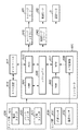
図4は記録モードによるサブヒータのPWM駆動信号のDuty設定シーケンスを示す図である。図4において、(a)は記録装置が画像データを入力して、記録する場合のサブヒータのPWM駆動信号のDuty比決定フローである。これによれば、ステップS10において動作モードを選択し、ステップS30では選択された動作モードに合わせてデューティ(Duty)テーブルを選択する。このテーブルについては後で説明する。そして、ステップS40では、記録中におけるサブヒータのPWM駆動信号のデューティ(Duty)比をデューティテーブルから選択し記録動作へ移行する。この時点で、記録装置1は記録待機状態になる。
FIG. 4 is a diagram showing a duty setting sequence of the PWM drive signal of the sub heater according to the recording mode. In FIG. 4, (a) is a flow of determining the duty ratio of the PWM drive signal of the sub heater when the recording apparatus inputs and records image data. According to this, the operation mode is selected in step S10, and the duty (Duty) table is selected in step S30 in accordance with the selected operation mode. This table will be described later. Then, in step S40, the duty (Duty) ratio of the PWM drive signal of the sub heater during recording is selected from the duty table, and the process shifts to the recording operation. At this point, the
また、(b)はPCなどのホスト装置610から印刷用の画像データが転送されてきた場合のDuty比決定フローである。これによれば、ステップS15ではホスト装置610などの外部機器から送られてきた記録装置の動作モードを指定するデータを受信し、ステップS20では、その受信データから記録装置の動作モードを判別する。そして、ステップS30〜S40では、前述のように、記録動作中のサブヒータのPWM駆動におけるDuty比を決定する。この場合も、メモリ内に保持しているテーブルから最適なDuty比を選択する。
Further, (b) is a flow of determining a duty ratio when image data for printing is transferred from a
図5はメモリに保持されるサブヒータのPWM駆動信号のDuty比を示すデューティテーブルを示す図である。この実施例では、図5に示すテーブルを参照して、動作モードに合わせて最適なDuty比を選択する。 FIG. 5 is a diagram showing a duty table indicating the duty ratio of the PWM drive signal of the sub heater held in the memory. In this embodiment, referring to the table shown in FIG. 5, the optimum duty ratio is selected in accordance with the operation mode.
図5に示す例では、デューティテーブルには4つの異なるデューティ比が格納されており、これらにテーブル番号(No.)として1〜4の数値が付されている。図5には、テーブル番号に対応してサブヒータのPWM駆動信号パルスの周期(T0)に対して、そのパルスがONとなる時間(T1)が異なるデューティ比が示されている。図5から分かるように、テーブル番号1〜4へと徐々にデューティ比が小さくなっている。従って、デューティ比の高いテーブル番号1が選択された場合には、サブヒータ加熱に要する消費電力は大きくなり、デューティ比の低いテーブル番号4が選択された場合には、サブヒータ加熱に要する消費電力は少なくなる。なお、図5では4つの異なるデューティ比のPWM駆動信号のパターンを例示したが、4つ以上の複数のPWM駆動信号のパターンが格納されても良いことは言うまでもない。
In the example shown in FIG. 5, four different duty ratios are stored in the duty table, and numerical values of 1 to 4 are given as table numbers (No.). FIG. 5 shows duty ratios that are different from the period (T 0 ) of the PWM drive signal pulse of the sub heater corresponding to the table number with respect to the time (T 1 ) in which the pulse is turned ON. As can be seen from FIG. 5, the duty ratio gradually decreases to
従って、この実施例におけるDuty比とは、サブヒータのPWM駆動信号パルスの1周期(T0)あたりのそのパルスがONしている時間(T1)の比率と定義することができる。 Therefore, the duty ratio in this embodiment can be defined as the ratio of the time (T 1 ) during which one pulse (T 0 ) of the PWM drive signal pulse of the sub heater is on.
記録装置には通常、多くの動作モードが備えられ、それぞれの動作モードに従って、使用されるインク吐出用ヒータの数が変化する。例えば、モノクロ印刷モードでは黒インクを吐出させるためのヒータのみが駆動し、カラー印刷モードでは、記録解像度によって使用されるヒータ数も異なる。高解像度印刷モードでは、ヒータ数は増加し、消費電力も大きくなる。また、高速印刷モードにすれば、使用されるインク吐出用ヒータの数を少なくして(即ち、消費電力を少なくして)記録が行われる。このように、インク吐出用ヒータの駆動数が変われば、そのヒータで消費する電力も変化する。 The printing apparatus is usually provided with many operation modes, and the number of ink discharge heaters used changes according to each operation mode. For example, in the monochrome printing mode, only the heaters for discharging black ink are driven, and in the color printing mode, the number of heaters used varies depending on the recording resolution. In the high resolution print mode, the number of heaters increases and power consumption also increases. Also, if the high-speed printing mode is selected, printing is performed with the number of ink discharge heaters used being reduced (that is, power consumption is reduced). Thus, if the number of driving of the ink discharge heater changes, the power consumed by the heater also changes.
従って、この実施例では、図4に示すステップS10又はステップS15において特定された動作モードに従ってサブヒータのPWM駆動信号のDuty比を決定する。このため、消費電力の大きい動作モードが選択された場合には、デューティ比の低いサブヒータのPWM駆動信号パルスを用いる。一方、消費電力の小さい動作モードが選択された場合には、デューティ比の高いサブヒータのPWM駆動信号パルスを用いるようにすることができる。このようにしてサブヒータを最大限駆動できるようにPWM駆動信号のDuty比を設定する。 Therefore, in this embodiment, the duty ratio of the PWM drive signal of the sub heater is determined in accordance with the operation mode specified in step S10 or step S15 shown in FIG. Therefore, when an operation mode with high power consumption is selected, the PWM drive signal pulse of the sub heater with a low duty ratio is used. On the other hand, when the operation mode with low power consumption is selected, the PWM drive signal pulse of the sub heater with high duty ratio can be used. Thus, the duty ratio of the PWM drive signal is set so that the sub heater can be driven to the maximum.
このようにすることで、一定の電力が割当てられた記録ヘッドにおいて、効率的にその電力を用いて記録ヘッドの温度制御を行うことが可能になる。例えば、キャリッジの移動が往路走査から復路走査に切り替わる時間帯では、記録ヘッド3からインク吐出を行うことはないので、記録ヘッド3に割当てられた電力を全て記録ヘッドの温度調整に用いることができる。この場合、以下に説明する短パルス加熱以外の余分な電力を最大限用いることができるデューティ比を選択してサブヒータの加熱に用いるようにできる。
By doing this, it becomes possible to efficiently control the temperature of the recording head using the power efficiently in the recording head to which a certain amount of power is allocated. For example, since ink is not ejected from the
また、インク吐出用ヒータの駆動とサブヒータ加熱を同時に行うことで記録に最適な温度まで迅速に記録ヘッドを加熱することが可能なる。インク吐出用ヒータの駆動に必要な消費電力は画像データなどに依存して計算から求めることができる。通常、記録装置と記録ヘッドの設計で、記録ヘッドに割り当て可能な最大電力(HPMAX)は予め決められる。このため、画像データなどに依存したインク吐出用ヒータの消費電力(DP)が計算されると、その結果、サブヒータ加熱に使用可能な最大消費電力(SHMAX)も算出される。従って、
SHMAX=HPMAX−DP ……(1)
という関係が成立する。
Further, by simultaneously performing the driving of the ink discharge heater and the sub heater heating, it is possible to rapidly heat the print head to a temperature optimum for printing. The power consumption required to drive the ink ejection heater can be determined from calculation depending on image data and the like. Usually, in the design of the recording apparatus and the recording head, the maximum power (HPMAX) assignable to the recording head is predetermined. Therefore, when the power consumption (DP) of the ink discharge heater depending on the image data etc. is calculated, as a result, the maximum power consumption (SHMAX) usable for the sub heater heating is also calculated. Therefore,
SHMAX = HPMAX-DP (1)
The relationship is established.
サブヒータの駆動電圧とそのときの負荷電流は決められているため、サブヒータをPWM制御することで、式(1)の関係を保持する限り、電源容量を増大させることなく、インク吐出用ヒータとサブヒータを同時に駆動することが可能となる。 Since the drive voltage of the sub heater and the load current at that time are determined, as long as the relationship of the equation (1) is maintained by PWM control of the sub heater, the ink discharge heater and the sub heater can be used without increasing the power supply capacity. Can be driven simultaneously.
このことから記録ヘッドがインク吐出を行なって記録を行なっている間も、定められた電源容量を超えないようにしてサブヒータ加熱を行うことが可能になる。 From this, it is possible to perform sub-heater heating without exceeding a predetermined power supply capacity even while the recording head discharges ink and performs recording.
次に、記録動作時における記録ヘッドの温度制御について図面を参照して説明する。 Next, temperature control of the recording head during the recording operation will be described with reference to the drawings.
図6は記録ヘッドの温度制御に係る種々の動作のタイムチャートである。 FIG. 6 is a time chart of various operations related to temperature control of the recording head.
図6に示すように、記録開始前やキャリッジ2が記録媒体上を往路走査後に停止し、再び復路走査するまでの時間をスキャン間と呼ぶ。キャリッジ走査では記録ヘッド3を搭載したキャリッジ2を停止状態からランプアップさせ、規定速度(v1)に達した後、定速動作となり、図6に示す区間で記録ヘッド3はインク吐出を行う。1走査終了後、キャリッジ2をランプダウンさせ動作安定を考慮した規定時間(スキャン間)の停止後、逆方向である復路方向へのランプアップを開始する。
As shown in FIG. 6, the time taken for the
図6から分かるように、記録ヘッド3のインク吐出を行う以外の時間に、記録ヘッド3の記録素子にインク吐出を生じさせない程度の短いパルス幅の駆動パルスを投入し、記録ヘッド3を加熱する。この動作を短パルス加熱という。
As can be seen from FIG. 6, a drive pulse having a short pulse width that does not cause ink ejection to the recording elements of the
また、短パルス加熱により、記録ヘッドのインク吐出用ヒータとその吐出口付近のインクの温度調整を行うことができる。これは、上述のように、各ノズルのインク吐出用ヒータにインクを吐出しない程度の長さのパルスを与えて加熱するものであり、一般的にパルス印加周波数も記録動作時のヒートパルスよりも長い周期となっている。記録ヘッドはインク吐出用ヒータに通電することで加熱されるため、記録動作時には短パルス加熱が行われることはなく、図6からも分かるように、キャリッジ走査のランプアップ、ランプダウン、停止時に実行される。 Further, the short pulse heating can adjust the temperature of the ink discharge heater of the recording head and the ink in the vicinity of the discharge port. As described above, this is to heat the ink discharge heater of each nozzle by giving a pulse of such a length as not discharging ink, and generally, the pulse application frequency is also higher than the heat pulse at the time of recording operation. It has a long cycle. Since the recording head is heated by energizing the ink discharge heater, short pulse heating is not performed during the recording operation, and as can be seen from FIG. 6, it is performed when ramping up, ramping down, and stopping the carriage scan. Be done.
一方、サブヒータ加熱は、サブヒータ抵抗体202に動作モードに応じたPWM駆動信号のDuty比で通電することにより実行される。記録ヘッド3のヘッドチップ201に2つ設けられたサブヒータ抵抗体202に選択通電することは可能で、通電の実施はヘッドチップ内の温度検出用ダイオードセンサ(不図示)の出力から得られるヘッドチップ温度により決定される。図3に示されているように、サブヒータ抵抗体202はインク吐出用ヒータとは別構成となっているため、図6に示すようにインク吐出中でも通電が可能である。
On the other hand, sub-heater heating is performed by energizing the
これら短パルス加熱とサブヒータ加熱を実行するタイミングはヘッド温度確認のタイミングで取得されたヘッドダイオードセンサからの出力に基づいて決定される。図6には、そのタイミングとして、t=a、t=b、t=c、t=dの4つのタイミングが例示されている。 The timing to execute the short pulse heating and the sub-heater heating is determined based on the output from the head diode sensor acquired at the head temperature confirmation timing. FIG. 6 exemplifies four timings of t = a, t = b, t = c, and t = d as the timings.
次に、記録ヘッドの温度調整をどのように行うのが、実際の記録動作と関係させて説明する。 Next, how to adjust the temperature of the recording head will be described in relation to the actual recording operation.
印刷ジョブをホスト装置610から受信すると、記録装置1は記録動作前の初期化動作を実行するが、そのときにヘッド温度確認動作も実行する。ヘッド温度(T)が所定の閾値より低い、即ち、ヘッド温度が低温である場合、上述した短パルス加熱やサブヒータ加熱を実行制御する。この動作はそのときのヘッド温度(T)で決定され、ヘッド温度によっては、(1)2つの加熱動作を実行しない、(2)短パルス加熱もしくはサブヒータ加熱のどちらかのみを実行する、(3)2つの加熱動作を実行するなどの選択制御が行われる。この選択は、記録ヘッドに割り当てられた電力で加熱動作に利用可能な電力をどのように用いれば、より短い時間でヘッド温度を規定値に上昇させることができるのかを考慮して行われる。
When a print job is received from the
図6に戻って説明を続けると、ヘッド温度確認t=aのタイミングでヘッド温度(T)が規定値に達していれば記録可能であると判断し、キャリッジ2の移動を開始する。図6に示した例では、t=aで、短パルス加熱とサブヒータ加熱の両方を実行する。この時点では、記録ヘッド3からはインク吐出を行っていないので、記録ヘッドに割り当てられた電力に余裕があるので、2つの動作を同時に実行して、ヘッド温度を迅速に規定値にまで加熱することができる。
Referring back to FIG. 6, if the head temperature (T) reaches a specified value at the timing of head temperature confirmation t = a, it is determined that recording is possible, and the movement of the
そして、記録ヘッド3が記録開始位置に到達するタイミングt=bで記録開始判断を行い、短パルス加熱とサブヒータ加熱を停止する。これによって、記録ヘッド3によるインク吐出動作に対して十分な電力を確保することができる。なお、上述のように、サブヒータ加熱については継続して駆動することも可能なので、図6が示唆するように、記録動作中にもサブヒータ加熱を再開することも可能である。
Then, the recording start determination is performed at timing t = b when the
例えば、文字画像印刷といったインク吐出量が少ない画像記録では、記録ヘッドの温度が低下し、ヘッド温度確認t=cのタイミングで記録ヘッドが規定値を下回ったという場合には、サブヒータ加熱を再開してヘッド温度を目標範囲に保つ制御を行う。インク吐出量が少ない画像記録の場合には、記録ヘッド3の記録素子を駆動してインク吐出を行うのに必要な電力が少ないので、たとえ、サブヒータ加熱を実行するのに必要な電力を確保することができる。
For example, in the case of image recording with a small ink ejection amount such as character image printing, if the temperature of the recording head decreases and the recording head falls below the specified value at the timing of head temperature check t = c, subheater heating is restarted. Control to keep the head temperature within the target range. In the case of image recording with a small amount of ink discharge, the amount of power required to drive the recording elements of the
インク吐出動作が終了し、キャリッジ2の1走査終了後、ヘッド温度確認t=dのタイミングでヘッド温度が規定値に達しない場合には、記録ヘッドの加熱動作を実行する。この場合でも、インク吐出中にサブヒータ加熱を実行していれば、記録ヘッドの温度の低下の程度が小さいので、より短い時間の短パルス加熱とサブヒータ加熱の動作でヘッド温度を規定値に上昇させることができる。
When the ink discharge operation is completed and the head temperature does not reach the specified value at the timing of the head temperature confirmation t = d after one scan of the
従って以上説明した実施例に従えば、記録ヘッドに割当てられた電力を有効に用いて短パルス加熱とサブヒータ加熱を選択動作させ、短時間で記録ヘッドの適正な温度に調整することができる。 Therefore, according to the embodiment described above, the short pulse heating and the sub heater heating can be selectively operated by effectively using the power allocated to the recording head, and the temperature of the recording head can be adjusted in a short time.
なお、短パルス加熱とサブヒータ加熱を同時に実行する際に、短パルス加熱に用いるヒートパルスのパルス幅が一定の場合にはサブヒータ加熱に用いるPWM駆動パルスのデューティ比を動作モードに係らず一定としても良い。この時には、記録ヘッドに割り当てられた電力から短パルス加熱に用いられる電力を差し引いた残りの電力を最も有効に使用できるデューティ比が選択されると良い。 When short pulse heating and sub heater heating are simultaneously performed, if the pulse width of the heat pulse used for short pulse heating is constant, the duty ratio of the PWM drive pulse used for sub heater heating will be constant regardless of the operation mode. good. At this time, it is preferable to select a duty ratio that can most effectively use the remaining power obtained by subtracting the power used for short pulse heating from the power allocated to the recording head.
実施例1では動作モードに応じてサブヒータPWM駆動パルスのDuty比を決定し、サブヒータを駆動させる例について説明した。この実施例では、図7〜図8を参照して、ヘッドランクに応じたサブヒータPWM駆動パルスのDuty比の設定動作について説明する。 In the first embodiment, an example in which the duty ratio of the sub heater PWM drive pulse is determined according to the operation mode and the sub heater is driven has been described. In this embodiment, the setting operation of the duty ratio of the sub heater PWM drive pulse according to the head rank will be described with reference to FIGS. 7 to 8.
サブヒータは抵抗体で構成されており、製造バラツキにより個々の記録ヘッドでその抵抗値が異なるため、同じ電圧でこれを駆動しても消費電力が変わってしまう。このバラツキの情報を記録ヘッドのヘッドランクと呼び、記録ヘッドに内蔵されている不揮発性メモリ(例えば、EEPROM)に記憶させている。従って、この実施例では、記録装置の起動シーケンス中に不揮発性メモリに記録されたヘッドランクを読取り、読取ったヘッドランクで最適なDuty比でサブヒータを駆動する。 The sub-heater is composed of a resistor, and the resistance value of each recording head is different due to manufacturing variations, so even if it is driven with the same voltage, the power consumption changes. This variation information is called a head rank of the recording head, and is stored in a non-volatile memory (for example, an EEPROM) built in the recording head. Therefore, in this embodiment, the head rank recorded in the non-volatile memory is read during the start-up sequence of the recording apparatus, and the sub-heater is driven at the optimum duty ratio with the read head rank.
図7はヘッドランク取得の構成を示したブロック図である。 FIG. 7 is a block diagram showing the configuration of head rank acquisition.
図7に示されるように、ヘッドランクは記録ヘッド3に内蔵される、例えば、EEPROMのような不揮発性メモリ3aに格納されている。ヘッドランクは、記録ヘッド3がキャリッジ2に装着され、記録装置1に電源が投入されたときに、不揮発性メモリ3aからコントローラ600のASIC603に読み込まれる。
As shown in FIG. 7, the head rank is stored in a non-volatile memory 3 a such as an EEPROM, which is built in the
図8は取得したヘッドランクに基づいた記録ヘッドの温度制御処理を示すフローチャートである。 FIG. 8 is a flowchart showing temperature control processing of the recording head based on the acquired head rank.
図8において、(a)は記録装置1に電源ON時のサブヒータPWM駆動信号のDuty設定の動作について説明したフローチャートである。また、(b)は記録装置1が電源ON中に記録ヘッドを交換した場合のサブヒータPWM駆動信号のDuty設定の動作を示すフローチャートである。
In FIG. 8, (a) is a flowchart for explaining the operation of setting the duty of the sub heater PWM drive signal when the power of the
記録装置1が電源OFFである場合、ユーザが記録ヘッドの交換を実施したかどうかを記録装置1は確認できないため、記録装置に電源をONした時には必ず記録ヘッドのランクの確認を行う。そのため、記録装置の電源がONされた場合、印刷ジョブの有無に関わらず図8(a)に示す初期化動作を実行する。
When the
図8(a)によれば、まず、ステップS101で記録ヘッドのヘッドランク値を取得する。これは、図7に示したように、記録ヘッド3の内部にあるEEPROMに書き込まれたランク情報を読み出すことによりなされる。次に、ステップS102では取得したヘッドランク値の評価を行う。これは、取得したヘッドランク値が規定値内にあるかどうかを調べることによってなされる。
According to FIG. 8A, first, at step S101, the head rank value of the print head is acquired. This is done by reading out the rank information written in the EEPROM inside the
ここで、取得したヘッドランク値が規定値外の値を示している場合は、記録ヘッドに故障が発生したか、或いは、記録装置1が対応していない記録ヘッドが装着されたと判断する。そのため、以降の記録動作を行うことは不可能として、処理はステップS106に進み、エラー処理を行い終了する。
Here, if the acquired head rank value indicates a value outside the specified value, it is determined that a failure has occurred in the recording head or a recording head not compatible with the
これらに対して、取得したヘッドランク値が規定値内の値を示している場合は、処理はステップS103に進み、現在、記録装置1に保持しているヘッドランク値(Hrank)と取得したヘッドランク値(Orank)とを比較する。なお、ユーザが記録装置1を購入し、そのインストール作業で初めて記録ヘッドが装着された場合には、記録装置1が保持しているヘッドランク値は工場出荷時の数値となっているので、その数値との比較を行う。
On the other hand, when the acquired head rank value indicates a value within the specified value, the process proceeds to step S103, and the head rank value (Hrank) currently acquired in the
その比較により、ステップS104において、Hrank≠Orank、即ち、保持しているヘッドランク値と取得したヘッドランク値が異なっている場合、記録ヘッドの交換が記録装置の電源OFF中に行われたと判断する。そして、処理はステップS105に進み、ステップS101で保持しているヘッドランク値を取得したヘッドランク値により置換し、保持すべきヘッドランク値を更新する。そして、この更新されたヘッドランク値に従って、図5に示したデューティテーブルからサブヒータ加熱に用いるPWM駆動信号のDuty比の適切な値を選択する。 According to the comparison, if it is determined in step S104 that Hrank 、 Orank, that is, the held head rank value and the acquired head rank value are different, it is determined that the printing head replacement was performed while the printing apparatus was powered off. . Then, the process proceeds to step S105, and the head rank value held in step S101 is replaced with the acquired head rank value, and the head rank value to be held is updated. Then, according to the updated head rank value, an appropriate value of the duty ratio of the PWM drive signal used for heating the sub heater is selected from the duty table shown in FIG.
これに対して、Hrank=Orank、即ち、保持しているヘッドランク値と取得したヘッドランク値が同じであれば、ヘッドランク値の更新は行わず、処理はそのまま終了する。 On the other hand, if Hrank = Orank, that is, if the held head rank value and the acquired head rank value are the same, the head rank value is not updated, and the process ends.
次に、図8(b)のフローチャートを参照して記録装置が電源ON中の記録ヘッド交換に伴うサブヒータのPWM駆動信号のDuty設定の動作について説明する。この動作は、ユーザ操作により記録ヘッド交換のために、記録装置のカバーが開状態であることが検出された場合に行われる。 Next, with reference to the flowchart of FIG. 8B, the operation of setting the duty of the PWM drive signal of the sub heater accompanying the replacement of the printing head while the printing apparatus is powered on will be described. This operation is performed when it is detected that the cover of the printing apparatus is open for the purpose of print head replacement by the user operation.
図8(b)によれば、ステップS107で記録ヘッドがキャリッジ2に装着された状態から非装着状態へ変化したかどうかを調べる。ここで、記録ヘッドがキャリッジ2から取り外されたことが検出されたなら、処理はステップS108に進み、記録ヘッドがキャリッジに装着されたかどうかを調べる。ここで、記録ヘッドがキャリッジ2に装着されたことが検出されたなら、処理はステップS109に進み、記録ヘッドの交換が行われたかを判断する。この処理は、図8(a)を参照して先に説明したランク取得処理と同様の処理である。
According to FIG. 8B, it is checked in step S107 whether or not the recording head has been mounted on the
ここで、以前とは異なる記録ヘッドが装着されたと判断されると、ヘッドランク値の更新が行われ、前述のように、取得したヘッドランク値に応じて適切なサブヒータ加熱時のPWM駆動信号のDuty比を決定する。そして、この記録ヘッドを使用する間はここで決定されたDuty比でのPWM駆動によりサブヒータ加熱が行われる。 Here, when it is determined that a recording head different from the previous one is attached, the head rank value is updated, and as described above, the PWM drive signal at the time of sub heater heating appropriate for the acquired head rank value. Determine the duty ratio. Then, while the recording head is used, sub-heater heating is performed by PWM drive at the duty ratio determined here.
以上のようにこの実施例に従えば、記録ヘッドが交換された場合には、その記録ヘッドに固有のヘッドランク値に応じたサブヒータ加熱ためのPMW駆動パルスのデューティ比を決定することができる。このようにして、各記録ヘッドに固有の特性を反映した適切なサブヒータ加熱が可能になる。 As described above, according to this embodiment, when the recording head is replaced, the duty ratio of the PMW drive pulse for heating the sub heater can be determined according to the head rank value unique to the recording head. In this way, appropriate sub-heater heating that reflects the characteristics unique to each recording head is possible.
1 記録装置、2 キャリッジ、3 記録ヘッド、201 ヘッドチップ、202 サブヒータ抵抗体、203 ノズル列
Claims (10)
前記第2のヒータを駆動するために用いる、デューティの異なる複数の駆動信号を格納する記憶手段と、
動作モードを入力する入力手段と、
前記入力手段によって入力された動作モードに基づいて、前記第1のヒータを駆動することで記録に用いられる第1の電力を算出する算出手段と、
前記算出手段により算出された第1の電力と、前記第1のヒータにインク吐出を生じさせない程度のパルスを投入して前記第1のヒータを駆動して前記記録ヘッドを加熱するために用いられる第2の電力とに基づいて、前記記憶手段に格納された前記複数の駆動信号から適切な駆動信号を選択する選択手段と、
前記選択手段により選択された駆動信号により、前記記録ヘッドの記録動作中と前記記録ヘッドが記録動作していない時間に前記第2のヒータを駆動して前記記録ヘッドを加熱するよう制御することが可能である制御手段とを有することを特徴とする記録装置。 The first heater provided to eject ink corresponding to each of the plurality of printing elements, and the second heater separately provided to heat the printing head separately from the first heater using a recording head, a recording apparatus for recording by out-discharge ink onto a recording medium,
Storage means for storing a plurality of drive signals of different duty used to drive the second heater;
Input means for inputting an operation mode;
Calculating means for calculating a first electric power used for recording by driving the first heater based on the operation mode inputted by the input means;
It is used to heat the recording head by driving the first heater by supplying the first electric power calculated by the calculation means and a pulse that does not cause ink discharge to the first heater. Selection means for selecting an appropriate drive signal from the plurality of drive signals stored in the storage means based on the second power;
Controlling the second heater to heat the recording head by the drive signal selected by the selection means during the recording operation of the recording head and during the time when the recording head is not performing the recording operation And a control means which is capable.
前記入力手段は、前記記録装置への電源が投入された場合と、記録ヘッドが取り外された後に装着された場合には、該装着された記録ヘッドからヘッドランクを入力し、
前記選択手段は、前記入力されたヘッドランクに基づいて、前記記憶手段に格納された前記複数の駆動信号から適切な駆動信号を選択することを特徴とする請求項1に記載の記録装置。 The recording head is replaceable, and the recording head incorporates a non-volatile memory storing a head rank indicating characteristics of the recording head.
The input means, in the case where power to the recording apparatus is turned on, when it is mounted after the recording head is removed, enter the head rank from 該装wear has been recording head,
The recording apparatus according to claim 1, wherein the selection unit selects an appropriate drive signal from the plurality of drive signals stored in the storage unit based on the input head rank.
前記記録ヘッドが記録動作していない時間とは、前記走査手段による前記キャリッジの移動が往路走査から復路走査に切り替わる間と、前記復路走査から前記往路走査に切り替わる間と、前記キャリッジのランプアップとランプダウンの間とを含むことを特徴とする請求項1乃至5のいずれか1項に記載の記録装置。 It further comprises a scanning means for reciprocating the carriage on which the recording head is mounted,
The time during which the recording head is not performing the recording operation includes the period during which the movement of the carriage by the scanning means is switched from the forward scanning to the backward scanning, and during the switching from the backward scanning to the forward scanning. The recording apparatus according to any one of claims 1 to 5, including a ramp down period.
前記デューティはPWM駆動信号の1周期あたりの前記PWM駆動信号のパルスがONしている時間の比率で定義されることを特徴とする請求項1乃至7のいずれか1項に記載の記録装置。 Each of a plurality of drive signals used to drive the second heater is a PWM drive signal,
The recording apparatus according to any one of claims 1 to 7, wherein the duty is defined by a ratio of time during which a pulse of the PWM drive signal is on per cycle of the PWM drive signal.
動作モードを入力する入力工程と、
前記入力工程において入力された動作モードに基づいて、前記第1のヒータを駆動することで記録に用いられる第1の電力を算出する算出工程と、
前記算出工程において算出された第1の電力と、前記第1のヒータにインク吐出を生じさせない程度のパルスを投入して前記第1のヒータを駆動して前記記録ヘッドを加熱するために用いられる第2の電力とに基づいて、メモリに格納された前記第2のヒータを駆動するために用いる、デューティの異なる複数の駆動信号から適切な駆動信号を選択する選択工程と、
前記選択工程により選択された駆動信号により、前記記録ヘッドの記録動作中と前記記録ヘッドが記録動作していない時間に前記第2のヒータを駆動して前記記録ヘッドを加熱するよう制御する制御工程とを有することを特徴とする記録ヘッドの温度制御方法。 The first heater provided to eject ink corresponding to each of the plurality of printing elements, and the second heater separately provided to heat the printing head separately from the first heater using a recording head, a temperature control method of the recording head in the recording apparatus for recording out ejection ink onto a recording medium,
An input step of inputting an operation mode;
A calculation step of calculating a first power used for recording by driving the first heater based on the operation mode input in the input step;
It is used to heat the recording head by driving the first heater by supplying the first electric power calculated in the calculation step and a pulse that does not cause ink discharge to the first heater. A selection step of selecting an appropriate drive signal from a plurality of drive signals with different duties used to drive the second heater stored in the memory based on the second power;
A control step of controlling to heat the recording head by driving the second heater during the recording operation of the recording head and during a time when the recording head is not performing the recording operation by the drive signal selected in the selection step. And a recording head temperature control method.
Priority Applications (1)
| Application Number | Priority Date | Filing Date | Title |
|---|---|---|---|
| JP2015109123A JP6506620B2 (en) | 2015-05-28 | 2015-05-28 | Recording apparatus and recording head temperature control method |
Applications Claiming Priority (1)
| Application Number | Priority Date | Filing Date | Title |
|---|---|---|---|
| JP2015109123A JP6506620B2 (en) | 2015-05-28 | 2015-05-28 | Recording apparatus and recording head temperature control method |
Publications (3)
| Publication Number | Publication Date |
|---|---|
| JP2016221782A JP2016221782A (en) | 2016-12-28 |
| JP2016221782A5 JP2016221782A5 (en) | 2018-06-28 |
| JP6506620B2 true JP6506620B2 (en) | 2019-04-24 |
Family
ID=57745157
Family Applications (1)
| Application Number | Title | Priority Date | Filing Date |
|---|---|---|---|
| JP2015109123A Active JP6506620B2 (en) | 2015-05-28 | 2015-05-28 | Recording apparatus and recording head temperature control method |
Country Status (1)
| Country | Link |
|---|---|
| JP (1) | JP6506620B2 (en) |
Families Citing this family (3)
| Publication number | Priority date | Publication date | Assignee | Title |
|---|---|---|---|---|
| JP2018144349A (en) * | 2017-03-06 | 2018-09-20 | ローランドディー.ジー.株式会社 | Inkjet printer |
| JP6965026B2 (en) * | 2017-05-29 | 2021-11-10 | キヤノン株式会社 | Recording device and recording method |
| JP7005211B2 (en) * | 2017-07-31 | 2022-01-21 | キヤノン株式会社 | Recording device, control method of recording device, and program |
Family Cites Families (6)
| Publication number | Priority date | Publication date | Assignee | Title |
|---|---|---|---|---|
| JPH07125215A (en) * | 1993-11-02 | 1995-05-16 | Canon Inc | Ink jet recording apparatus |
| JPH0858077A (en) * | 1994-08-24 | 1996-03-05 | Canon Inc | Ink jet apparatus and ink jet head |
| JP2004160684A (en) * | 2002-11-08 | 2004-06-10 | Canon Inc | Ink jet recorder |
| KR20060135452A (en) * | 2005-06-25 | 2006-12-29 | 삼성전자주식회사 | Printing apparatus with head chip spitting ink and head chip temperature control method thereof |
| JP2010214866A (en) * | 2009-03-18 | 2010-09-30 | Canon Inc | Recorder and recording control method |
| JP2012176572A (en) * | 2011-02-28 | 2012-09-13 | Seiko Epson Corp | Heating source control method, heating source control device, and inkjet recording apparatus with the device |
-
2015
- 2015-05-28 JP JP2015109123A patent/JP6506620B2/en active Active
Also Published As
| Publication number | Publication date |
|---|---|
| JP2016221782A (en) | 2016-12-28 |
Similar Documents
| Publication | Publication Date | Title |
|---|---|---|
| US6616257B2 (en) | Printing head, printing method and apparatus using same, and apparatus and method for correcting said printing head | |
| JPH0631932A (en) | Ink-jet recording device | |
| US7384115B2 (en) | Method for controlling a printhead | |
| JP5032964B2 (en) | Head substrate, recording head, head cartridge, and recording apparatus | |
| US7341324B2 (en) | Pre-warming portions of an inkjet printhead | |
| JP6506620B2 (en) | Recording apparatus and recording head temperature control method | |
| JP3099549B2 (en) | Preliminary head driving method for inkjet recording apparatus | |
| JP4596757B2 (en) | Recording head test equipment | |
| KR100435011B1 (en) | Printing apparatus and printing control method | |
| US6761424B2 (en) | Image print apparatus and control method thereof | |
| US6276776B1 (en) | Ink-jet printer and temperature control method of recording head | |
| US8474941B2 (en) | Inkjet printing apparatus and inkjet printing method | |
| JP2005041136A (en) | Inkjet recording device and inkjet recording method | |
| JP3888381B2 (en) | Inkjet recording device | |
| JP2011189707A (en) | Recording apparatus and determining method of ejection condition | |
| JP5523184B2 (en) | Recording device | |
| JP2003089196A (en) | Ink jet recorder and its ink temperature controlling method | |
| JP3486547B2 (en) | Inkjet printer and method of controlling temperature of recording head | |
| JP4780882B2 (en) | Inkjet recording apparatus and inkjet recording method | |
| JP2016107446A (en) | Recording apparatus and failure detection method for recording head | |
| JP2006289624A (en) | Recorder and control method of recorder | |
| KR20080114018A (en) | Ink jet image forming apparatus and control method thereof | |
| JP2023151558A (en) | recording device | |
| JP6300551B2 (en) | Liquid ejection device and liquid ejection method | |
| JP4455013B2 (en) | Recording head driving method, recording head, and recording apparatus |
Legal Events
| Date | Code | Title | Description |
|---|---|---|---|
| A521 | Written amendment |
Free format text: JAPANESE INTERMEDIATE CODE: A523 Effective date: 20180514 |
|
| A621 | Written request for application examination |
Free format text: JAPANESE INTERMEDIATE CODE: A621 Effective date: 20180514 |
|
| A977 | Report on retrieval |
Free format text: JAPANESE INTERMEDIATE CODE: A971007 Effective date: 20190213 |
|
| TRDD | Decision of grant or rejection written | ||
| A01 | Written decision to grant a patent or to grant a registration (utility model) |
Free format text: JAPANESE INTERMEDIATE CODE: A01 Effective date: 20190301 |
|
| A61 | First payment of annual fees (during grant procedure) |
Free format text: JAPANESE INTERMEDIATE CODE: A61 Effective date: 20190329 |
|
| R151 | Written notification of patent or utility model registration |
Ref document number: 6506620 Country of ref document: JP Free format text: JAPANESE INTERMEDIATE CODE: R151 |