JP4780882B2 - Inkjet recording apparatus and inkjet recording method - Google Patents
Inkjet recording apparatus and inkjet recording method Download PDFInfo
- Publication number
- JP4780882B2 JP4780882B2 JP2001303437A JP2001303437A JP4780882B2 JP 4780882 B2 JP4780882 B2 JP 4780882B2 JP 2001303437 A JP2001303437 A JP 2001303437A JP 2001303437 A JP2001303437 A JP 2001303437A JP 4780882 B2 JP4780882 B2 JP 4780882B2
- Authority
- JP
- Japan
- Prior art keywords
- pulse
- heaters
- voltage
- recording
- detected
- Prior art date
- Legal status (The legal status is an assumption and is not a legal conclusion. Google has not performed a legal analysis and makes no representation as to the accuracy of the status listed.)
- Expired - Fee Related
Links
Images


Description
【0001】
【発明の属する技術分野】
本発明は、インクジェット記録装置およびインクジェット記録方法に関し、詳しくは、電気熱変換素子を用いインクに熱エネルギーを作用して気泡を生じさせ、この気泡の圧力によってインクを吐出する方式における上記電気熱変換素子の駆動に関するものである。
【0002】
【従来の技術】
近年、プリンタに代表される記録装置が普及しており、そのような記録装置の一つの傾向として、高速記録、高解像度記録、低騒音記録などを可能とするものが求められている。このような要求に応える記録装置として、インクジェット方式の記録装置をあげることができる。インクジェット方式は、記録ヘッドの吐出口からインク(記録液)滴を吐出飛翔させ、これを被記録媒体に付着させて記録する方式である。これにより、上述の高速記録等が比較的容易に実現可能であるとともに、記録ヘッドと被記録媒体とが非接触で記録を行なうことから、インク定着の乱れなどがなく比較的画像の安定した記録が可能となる。
【0003】
このようなインクジェット方式のうち、電気熱変換素子が発生する熱エネルギーを利用してインクを吐出する方式は広く用いられている方式であり、この方式では、電気熱変換素子(以下、「ヒータ」ともいう)の両端に所定電圧の駆動信号を印加することにより熱エネルギーを発生する。
【0004】
このヒータやこれに電圧を印加するための配線電極などは、半導体製造プロセスと同様の技術を用いて基板に形成され、これを元に記録ヘッドが製造される。このため、例えば、記録ヘッドの複数の吐出口それぞれに設けられるヒータについて、それらヒータの各々を構成する発熱抵抗体膜の製造ばらつきによって、抵抗値にばらつきを生じることがある。そして、その結果、記録ヘッドの複数のヒータに一定の電圧を印可しても、上記抵抗値のばらつきに応じてヒータ間で電流がばらついてしまい、最終的に、発生する熱エネルギーの違いを生じ、吐出口によってはインク吐出が良好になされないなどの弊害を生じることがある。また、一つの記録ヘッドにおける複数のヒータ間にばらつきがない場合でも、記録ヘッド間でばらつきがある場合もある。
【0005】
このような問題に対し、従来、製造時に、予め記録ヘッドにおける複数のヒータそれぞれのの抵抗値を測定し、これに基づいてヒータに供給する駆動パルスのパルス幅を設定することが行なわれている。また、ヒータの抵抗値だけでなく、配線電極の抵抗値も考慮してパルス幅を設定することも行なわれている。
【0006】
ところで、複数の吐出口(以下、「ノズル」ともいう)を備えたマルチノズルヘッドの駆動に関して、いわゆる時分割駆動(あるいはブロック駆動)が知られている。例えば、記録ヘッドのノズルが配列する方向に沿った直線である、罫線を最も簡易な制御で記録する方法は、記録ヘッドの複数のノズルから同時に吐出を行うものである。しかし、このように記録ヘッドの全てのノズルを同時に駆動すると、特に、記録の高速化や高密度化などのためノズル数が多い場合には、これによって大きな電圧降下を生じたり、一時的に共通液室内の負圧のレベルが高くなって各ノズルへのインクのリフィルが間に合わなくなったりすることがある。そこで、記録ヘッドの複数のノズルをいくつかのブロックに分け、これらのブロック毎に時分割で駆動を行う時分割駆動方式が採用されることが多い。この時分割駆動方式によれば、各ノズルからの吐出インクによって記録されるインクドットはブロック毎にずれることになるが、記録ヘッドにおける各ノズルの位置を調整したり、ノズル列を傾けるなどしてこのずれができるだけ目立たないようにしている。
【0007】
しかし、更なる高速記録、高解像度記録などの要求によって、ノズル数を数百から数千とし、また、各ヒータの駆動周波数を数十kHzとすることがある。この場合、ブロック毎に同時駆動するヒータ数が増し、そのため、瞬間最大電流が増して電源電圧の配線電極等による電圧降下はさらに大きくなる。記録データによって同時に駆動されるヒータの数は変化することはもちろんであるが、このようにブロック当たりのヒータ数が多い場合には、上述の比較的大きな電圧降下によって、それぞれのヒータに吐出に必要な電圧が印加されなくなり、不吐出や吐出量が不充分になるなどの吐出不良を生ずることがある。
【0008】
この問題を解決するため、配線抵抗を極力小さくして最大電圧降下分のマージンをもたせるべく、ヒータ駆動信号の設定電圧を大きくすることが、従来行なわれている。
【0009】
しかしながら、上述の設定電圧を大きくする方法では、ヒータが耐え得る電圧に一定の限界があるため、ヒータ数の増大に応じて、単純に設定電圧を大きくすることはできない。また、記録データによって、同時駆動するヒータ数が少ない場合は、ヒータに過大なエネルギーが投入され、熱効率が低下することはもとより、ヒータの耐久性を損なうという問題を派生する。
【0010】
これを解決するため、例えば特開平9−11504号公報に開示されるように、同時駆動するヒータ数をカウントし、駆動信号のパルス幅や電圧値を制御する方法が知られている。これは、同時駆動するヒータ数をカウントし、これに基づいて電圧降下分を計算し、その降下分に応じてパルス幅や電圧値を制御するものである。これにより、上述の吐出不良を防止することが可能となる。この方法は、同時駆動するヒータの数に基づいて計算された適性なパルス幅もしくは電圧値が設定されるため、熱効率やヒータの耐久性に関して有効である。
【0011】
しかし、この方法における電圧値の制御は実際的ではない。電圧降下分に応じた補償を行うには、高精度、かつ高速な電圧値の制御が必要であり、現在知られる電圧制御電源では、コストが多大になるだけでなく、技術的にも困難であるからである。このため、上記方法では、専らパルス幅を制御することによって、同時駆動による電圧降下分の発泡エネルギーの補償を行なうのが一般的である。
【0012】
【発明が解決しようとする課題】
以上説明したように、ヒータ駆動に関する配線抵抗のばらつきや複数ヒータの同時駆動による電圧降下による吐出不良の問題を解決すべく、ヒータ駆動信号のパルス幅を制御することが行われている。
【0013】
しかしながら、上述したパルス幅の制御では、パルス幅自体が大きくなり駆動周期に適合しなくなったり、また、パルス幅の制御幅が広くなって、吐出量や吐出速度が変動してしまうという問題を派生する場合がある。
【0014】
図1はヒータ駆動信号のパルス幅と吐出量との関係を示した線図である。この関係は、駆動信号を矩形の単一パルスとし、そのパルスの電圧値を一定とし、また、電圧降下分を差し引いた、実際に吐出に寄与するパルスのエネルギーはパルス幅にかかわらず一定とした条件で得られたものである。すなわち、パルスのエネルギーはいずれのパルス幅でも、発泡を生じ得る限界の発泡臨界エネルギーに対して一定の比率(1より大)のエネルギーを有する。
【0015】
図1に示すように、吐出量は、パルス幅の比較的小さい領域において大きく変動する。上述した従来のいずれのパルス制御でも、この大きく変動する領域は使用せず、基本的なパルス幅を長くして吐出量変動が少ない実使用領域においてパルス幅制御を行なうようにしている。これにより、制御によってパルス幅を変更しても、それ程吐出量や吐出速度が変化しないようにすることを可能としている。
【0016】
しかしながら、さらなる高速駆動をする場合には駆動周期が短くなるため、上記比較的長い幅のパルスがこのような駆動周期内に入らなくなってしまい、記録ヘッドの駆動に支障をきたすことがある。また、大きな電圧降下に応じて適切にパルス幅制御を行なうには、その制御幅も大きくならざるをえず、その結果、その制御領域に図1に示す吐出量が大きく変動する領域が含まれてしまうことがある。そして、パルス幅制御によって吐出量や吐出速度が変動し、記録品位を著しく劣化させるという問題を生じる。
【0017】
本発明は、このような問題を解決するためになされたものであり、その目的とするところは、記録ヘッドにおけるヒータ抵抗、配線抵抗の変化や、複数ヒータを同時駆動するときの電圧降下の変化に応じてパルス幅を制御する場合に、その制御範囲を適切に定めることを可能として安定した吐出を行なうことができるインクジェット記録装置およびインクジェット記録方法を提供することにある。
【0018】
【課題を解決するための手段】
そのために本発明では、複数のヒータのそれぞれに電圧パルスを供給することにより発生する熱エネルギーを利用しインクを吐出する記録ヘッドを用い、被記録媒体にインクを吐出して記録を行なうインクジェット記録装置において、前記複数のヒータに電圧パルスを供給するときの当該電圧パルスの電圧降下の程度を示す量を検出する検出手段と、該検出手段が検出した量に応じて、互いに間隔をおいた第1パルスと第2パルスとで構成されるダブルパルスのうちの先行する前記第1パルスの幅を前記電圧降下の程度を示す量が少なくなるほど長くなるように制御する制御手段と、を備えたことを特徴とする。
【0019】
他の形態では、複数のヒータのそれぞれに電圧パルスを供給することにより発生する熱エネルギーを利用しインクを吐出する記録ヘッドを用い、被記録媒体にインクを吐出して記録を行なうインクジェット記録装置において、前記複数のヒータに電圧パルスを供給するときの当該電圧パルスの電圧降下の程度を示す量を検出する検出手段と、該検出手段が検出した量に応じて、前記電圧パルスとしての分割パルスにおける先行するパルスの幅の比率を前記電圧降下の程度を示す量が少なくなるほど大きくなるように制御する制御手段と、を備えたことを特徴とする。
【0022】
また、複数のヒータのそれぞれに電圧パルスを供給することにより発生する熱エネルギーを利用しインクを吐出する記録ヘッドを用い、被記録媒体にインクを吐出して記録を行なうインクジェット記録方法において、前記複数のヒータに電圧パルスを供給するときの当該電圧パルスの電圧降下の程度を示す量を検出し、該検出ステップが検出した量に応じて、前記電圧パルスとしての分割パルスにおける先行するパルスの幅を前記電圧降下の程度を示す量が少なくなるほど長くなるように制御する、ステップを有したことを特徴とする。
【0023】
他の形態では、複数のヒータのそれぞれに電圧パルスを供給することにより発生する熱エネルギーを利用しインクを吐出する記録ヘッドを用い、被記録媒体にインクを吐出して記録を行なうインクジェット記録方法において、前記複数のヒータに電圧パルスを供給するときの当該電圧パルスの電圧降下の程度を示す量を検出し、該検出ステップが検出した量に応じて、前記電圧パルスとしての分割パルスにおける先行するパルスの幅の比率を前記電圧降下の程度を示す量が少なくなるほど大きくなるように制御する、ステップを有したことを特徴とする。
【0026】
以上の構成によれば、複数のヒータに駆動信号を供給するときの当該駆動信号の電圧降下の程度を示す量に応じて、駆動信号を単一パルスからダブルパルスの駆動信号に変更し、または、パルス波形を求めるので、さらには、分割パルスにおける先行するパルスの幅の比率を前記電圧降下の程度を示す量が少なくなるほど大きくなるように制御するので、単一パルスでヒータを駆動するときにそのパルス幅である通電時間が、吐出量が変動する範囲のものであるときは、それをダブルパルスまたは変更した別の波形のパルスでヒータを駆動することができ、これにより、吐出量が変動しない駆動信号によってインク吐出を行なうことが可能となる。
【0027】
【発明の実施の形態】
以下、図面を参照して本発明の実施形態を詳細に説明する。
【0028】
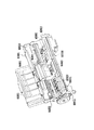
図2は、本発明の一実施形態にかかるインクジェットプリンタの主要な構成を示す斜視図である。
【0029】
本実施形態のプリンタは、それぞれブラック(K)、シアン(C)、マゼンタ(M)、イエロー(Y)のインクを吐出する四つの記録ヘッドを用いるものである。これらの記録ヘッドおよびインクタンクは、図4および5で後述されようにカートリッジ形態のものであり、キャリッジM4001に着脱自在に装着されて用いられる。なお、図2は、記録ヘッドとインクタンクからなるカートリッジが取外された状態を示している。それぞれの記録ヘッドは、図3に示すように、384個のノズルを配設し、ノズル配列密度は360dpiである。
【0030】
以上の記録ヘッドは、インクタンクとともにキャリッジM4001に装着され、キャリッジM4001がガイド軸に案内されながらキャリッジモータ(不図示)の駆動力によって移動することにより、各記録へッドは記録用紙(不図示)に対して走査を行ない、この走査の間に記録データに従って記録用紙にインクを吐出し記録を行なうことができる。より詳しくは、記録開始前ホームポジションに位置しているキャリッジM4001は、記録開始命令があると、図中右方向(往走査方向)に移動する。この間に、各記録ヘッドのノズルから、記録データに従いインクを吐出して記録用紙上にノズル列に対応した幅の記録を行なう。記録ヘッドからのインク吐出は、キャリッジの移動位置を検出するエンコーダの位置検出信号に基づいたタイミングで、各ノズルに対応して設けられるヒータを駆動することによって行なわれる。そして、記録用紙における所定の記録領域の端部までの記録を終了すると、キャリッジM4001はホームポジションに戻り、同様に、上述の往走査方向の走査を行ない、記録を行う。または、往復記録の場合は、上気往走査とは逆の復走査方向においても同様の記録動作を行う。そして、これらの走査の間に、紙送りローラM3001が所定量回転することにより上記幅だけ紙送りを行う。この様にして記録ヘッドの走査と紙送りを繰り返えすことにより、用紙上に所定の画像等の記録を行なうことができる。
【0031】
M3001は紙送りローラであり、自動給送装置M3022から給紙される記録用紙を上記記録ヘッドの走査による記録幅に応じた量搬送する。
【0032】
キャリッジM4001は非記録時、あるいは吐出回復処理などを行う時には、図中の右端に位置するホームポジションに移動し、ここで記録を待機し、また、回復ユニットM5000による吐出回復処理を行なうことができる。
【0033】
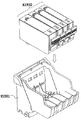
図4は、図2に示した本実施形態のインクジェットプリンタで用いられる記録ヘッドヘッドカートリッジを示す斜視図であり、図5はそれを構成する記録ヘッドとインクタンクとを相互に取外した状態で示す斜視図である。
【0034】
これらの図に示すように、記録ヘッドカートリッジH1000は、記録ヘッドH1001とこれに対して着脱自在に設けられたインクタンクH1900(H1900K,H1900C,H1900M,H1900Y)とで構成されている。すなわち、インクタンクH1900Kはブラックインクを収容し、同様にインクタンクH1900Cはシアンインクを、インクタンクH1900Mはマゼンタインクを、インクタンクH1900Yはイエローインクをそれぞれ収容する。そして、インクタンクH1900K,H1900C,H1900M,H1900Yはそれぞれが個別に記録ヘッドH1001に対して着脱可能に構成されており、これにより、それぞれのインクタンクを個別に交換することができる。これにより、プリンタにおける記録のためのランニングコストを低減することが可能となる。
【0035】
記録ヘッドH1001は、インクタンクH1900をそれぞれ装着するための装着部を一体に備えるものであり、これらの図において下方に、図3に示したノズル列を配設した吐出口面が面している。
【0036】
この記録ヘッドカートリッジH1000は、図2に示したインクジェットプリンタのキャリッジM4001に対して着脱自在に装着され、その装着時にはキャリッジM4001に設けられたヘッドセットレバーM4007(図2参照)によってその装着および位置決めの操作が行なわれる。また、この装着によって記録ヘッドカートリッジH1000の電気接点基板とキャリッジM4001の電気的接点基板とが相互に接続固定される。
【0037】
図6は、上述した本実施形態にかかるインクジェットプリンタの制御構成を示すブロック図であり、特に、記録ヘッド駆動における駆動信号の制御構成を示すものである。
【0038】
図において、画像入力部161は、ホストコンピュータやビデオ機器等からの画像信号あるいはCCD等を備えたスキャナによって読み取られた画像信号を、輝度信号R、G、Bとして入力する。また、操作部162は、操作者が各種パラメータの設定や記録開始などの指示をするための各種キーを備える。
【0039】
CPU163はROM164に格納された各種プログラムに従い、図10にて後述される、本実施形態の駆動信号制御に係わる処理を含み、本プリンタ全体の制御を実行する。ROM164は、本プリンタで行なわれる動作や処理を実行するためのプログラム等を格納し、図では、後述の駆動信号制御に関して本発明の第一の実施形態にかかる同時駆動ビット−ブロック時間テーブルおよび第二の実施形態にかかるヒータ抵抗駆動パルステーブルと、両実施形態で用いる駆動パルス幅分割テーブルとが示されている。同時駆動ビットカウンタ170は、上記第一の実施形態で用いられ、RAM165の記録データ展開エリアaに展開された記録データから同時駆動のビット数をカウントするカウンタであり、CPU163は図10にて後述されるように、このカウンタ値に基づきROM164の同時ビット−駆動パルステーブルを参照する。RAM165は、上述の記録データ展開用エリアa、設定ブロック時間格納エリアb、設定パルス幅格納エリアcをはじめとして、CPU163の処理実行におけるワークエリアを有している。
【0040】
画像信号処理部166は、CPU163の制御の下、後述する画像信号処理を行う。プリンタエンジン部167は、図2にその概略が示される記録機構であり、画像信号処理部166の処理によって得られる記録データに基づいてインクドットの画像を形成する。さらに、バスライン168は、本制御構成におけるアドレス信号、データ、制御信号等を伝送する。
【0041】
図7は、本実施形態の記録ヘッドに構成されるヘッド駆動回路の構成を示す回路図である。
【0042】
本実施形態の各記録ヘッドは、同図に示す回路を3セット備え、これにより、384個の電気熱変換素子(ヒータ)71を24個(8個×3セット)ずつ16のブロックに分割し、これらヒータをブロックごとに時分割で駆動する。すなわち、本実施形態では、それぞれのセットの回路において、ラッチ74から出力される8ビットの記録データそれぞれに対応してドライバ76が設けられ、これら8個のドライバ76それぞれでは、デコーダ77から出力される16の異なるブロックイネーブル信号に応じて、それぞれのドライバにおける16個のヒータの中からブロックイネーブル信号で示されるブロックのヒータを選択する。この回路による駆動の詳細を、図8および9に示すタイミングチャートに従って説明する。
【0043】
図8は、一つのセットの回路における、1ブロック分の記録データおよび駆動ブロックを示すデータの転送タイミングを示すタイミングチャートである。
【0044】
同図に示すように、CLK端子(図7)に入力するクロック信号CLKのエッジタイミングに従って、DATA端子(図7)から信号DATA+BEが入力する。信号DATA+BEのうち、図8の表に示すように、入力順序1〜8で入力する記録データDATA0〜7は、記録データ、すなわち、それぞれヒータのオンまたはオフを示すものであり、8ビットのシフトレジスタ72(図7)に順次格納される。また、同表の入力順序9〜12で入力するブロック選択データBE0〜3は、図9にて説明されるように、これらの組合せたデータがデコードされて駆動すべきブロックを選択するものであり、4ビットシフトレジスタ73(図7)に順次格納される。
【0045】
1ブロック分の記録データ及びブロック選択データの転送が終わると、LT端子(図7)を介して入力する、ラッチ信号LTの立ち上がりエッジによって、シフトレジスタ72およびシフトレジスタ73のそれぞれのデータは、それぞれ8ビットのラッチ74および4ビットのラッチ75によってラッチされる。
【0046】
図9は、記録ヘッドのノズル列に対応した1コラム分のヒータ駆動に関するタイミングチャートである。すなわち、最初の、図8にて説明した1ブロック分のデータの転送が終わると、次のブロックより、データの転送とヒータの駆動は同時に行われるが、図9は、このデータ転送とヒータ駆動について16ブロック分、つまり駆動の1周期分に関するタイミングチャートを示している。
【0047】
図9において、LT信号に従い、4ビットラッチ75にラッチされたブロック選択データはデコーダ77(図7)に入力し、図9の表に示すように、16組のデコーダ出力である、それぞれが16ビットのブロックイネーブルデータBLE0〜15のいずれかにデコードされて出力される。すなわち、図9の表に示すように、ブロック選択データBE0〜3それぞれの内容であるL(0)またはH(1)の組合せが上記1ブロックの転送ごとに順次に変化し、これに応じて駆動が可能なブロック(ブロックイネーブルデータBLEがHとなるブロック)が順次選択される。また、上述のラッチ信号LTの次に、HE端子(図7)よりヒートイネーブル信号HEが入力される。ここで、ヒートイネーブル信号HEはLowアクティブである。
【0048】
そして、図7に示す回路において、HE端子はすべてのドライバに接続している。また、ブロックイネーブルデータBLE0〜15の信号線の全ては、それぞれが16個のヒータ71に対応した8個のドライバ76に接続している。一方、8ビットラッチ74から出力する8本の信号線は、上記8個のドライバ76のうち、対応するドライバ76に個々に接続する。これにより、記録データとブロックイネーブルデータBLEのマトリクスが構成されて128個×3セット分のヒータ71についてブロック駆動が可能となる。
【0049】
より詳細には、ヒートイネーブル信号HEは、ヒータ駆動信号のパルス幅を設定するものである。また、記録データDATAとヒートイネーブル信号HEは、各ドライバ76において16個のヒータそれぞれに対応して設けられた16個のAND回路(不図示)の全てに入力し、また、ブロックイネーブル信号BLEのそれぞれは、上記16個のAND回路のうち対応するAND回路にそれぞれ入力する。そして、記録データDATAとヒートイネーブル信号HEとブロックイネーブル信号BLEの全てがオン(H)の場合は、図9に示す電流VHが対応するヒータ71に流れることになる。このように、ブロックごとにブロックイネーブルデータBLE0〜BLE15が順次に転送されることにより、記録データに従い、順次ブロックごとにそのブロックのヒータが駆動され、これにより、1コラム分の128個×3セット分のヒータが1駆動周期Tの期間内に駆動される。以降、同様にして記録ヘッドの走査に同期して、1コラム分ずつヒータの駆動が行なわれて行く。
【0050】
(実施形態1)
次に、以上説明した本実施形態のインクジェットプリンタにおける、本発明の第一の実施形態による駆動信号制御について以下に説明する。
【0051】
図10は、記録時における制御フローチャートである。また、図11は図6に示したROM164における同時ビット−駆動パルステーブルを示し、図12は、図6に示すROM164における駆動パルス幅分割テーブルを示すそれぞれ模式図である。
【0052】
まず、記録のスタンバイ状態から、ステップS100において、画像データを画像入力部161を介して入力し、ステップS101で、画像信号処理部166のデータバッファに一時的に格納した後、所定のタイミングで、画像処理部において輝度濃度変換、マスキング等、所定の画像処理を行い、最終的に2値化処理を行って2値の記録データを得る。そして、ステップS102において、この記録データはRAM165のデータ展開用エリアaに展開される。
【0053】
次に、ステップS103において、同時駆動ビットカウンタ170はデータ展開用エリアaに展開された記録データから、1カラム分の各ブロックの同時駆動するヒータの数(本明細書および図面では、これを「ビット数」とも言う)をそれぞれカウントし、ステップS104で、図11に示す、ROM164の同時ビット−駆動パルステーブルを参照して、それぞれブロックごとに駆動信号のパルス幅を求める。
【0054】
本実施形態では、図7にて説明したように各ブロックについて、同時駆動数は記録データに応じ0〜24ビットのいずれかとなる。図11の同時ビット−駆動パルステーブルに示すように、同時駆動数が0〜3のときはパルス幅は1.6μs、4〜7のときは1.8μsというようにパルス幅が求められる。
【0055】
このパルス幅とは、ヒータの駆動信号を所定電圧値VHの電圧パルスであって、その形状が矩形のシングルパルスとしたときのパルス幅、すなわち、通電時間である。図1について前述したように、このような単一パルスを用いてヒータを駆動するときは、そのパルス幅が短かい領域で吐出量が大きく変動するため、このような領域である、通電時間が1.6μs〜3.6μsの範囲では、次にしめすように駆動信号をいわゆるダブルパルスに変更することにより、吐出量の変動を生じないようにする。なお、本実施形態のテーブルによって得られるダブルパルスの合計のエネルギーとこれと対応する上記基本となるシングルパルスのエネルギーは、いずれのパルス幅でもそれぞれ等しく、また、前述したように、それぞれの実際に吐出に寄与するエネルギーは等しく臨界発泡エネルギーに対して一定の比率を有するものである。また、その場合、電圧値も上記シングルパルスとダブルパルスは等しく、且つ一定である。
【0056】
以上のテーブル参照の後、次のステップS105で、上記で求めたパルス幅に従い、ブロックごとに、図12に示す、ROM164の駆動パルス幅分割テーブルを参照し、それぞれのブロックの駆動信号波形を設定する。本実施形態では、駆動信号波形として、パルスが2つに分割されたいわゆるダブルパルスを波形の基本とし、それぞれのパルス幅を変えることによって上記シングルパルスとは異なる波形とする。
【0057】
図12におけるP1、P2、P3とは、図13に示すように、2つの分割されたパルスの幅およびこの2つのパルスの間の休止時間を意味するものである。なお、本実施形態では、2つの矩形パルスとしたが、3つ以上の矩形パルスでも、矩形とならないパルスとしても良い。このように、複数のパルスからなる複数パルスは、その加熱によってインクにおける発泡を伴わない加熱を行う少なくとも一つのプレパルス(先行するパルス)と発泡を伴うメインパルスとそれらのパルス間に休止期間を含むものである。また、シングルパルスは、発泡によってインクを吐出する単一のパルスである。
【0058】
図12の駆動パルス分割テーブルに示すように、パルス幅が1.6μsのときは、P1(プレパルス)=0.7μs、P2(休止時間)=0.9μs、P3(メインパルス)=0.9μs、パルス幅が1.8μsのときは、P1(プレパルス)=0.5μs、P2(休止時間)=0.8μs、P3(メインパルス)=1.3μs、パルス幅が2.0μsのときは、P1(プレパルス)=0.4μs、P2(休止時間)=0.7μs、P3(メインパルス)=1.6μs、パルス幅が2.5μsのときは、P1(プレパルス)=0.3μs、P2(休止時間)=0.6μs、P3(メインパルス)=2.2μs、パルス幅が3.0μsのときは、P1(プレパルス)=0.2μs、P2(休止時間)=0.5μs、P3(メインパルス)=2.8μs、パルス幅が3.6μsのときは、P1(プレパルス)=0.0μs、P2(休止時間)=0.0μs、P3(メインパルス)=3.6μs、というように、各々のブロックについて駆動信号のパルス幅が設定される。これから明らかなように、同時駆動ビット数に基づいて求められるパルス幅が3.0μsまでは駆動信号はダブルパルス(複数パルス)であり、それぞれプレパルス、休止期間、メインパルスの幅が異なることによってそれぞれの波形を異ならせるが、求められるパルス幅が3.6μsのときは、上記各幅を異ならせることによって波形自体はシングルパルスとなる。しかし、これは、ダブルパルスにおいて、プレパルスおよび休止期間をそれぞれ0μsとしたものと考えることもできる。
【0059】
このように同時駆動ビット数とパルス幅の関係を見ると、同時駆動ビット数が少ない程、プレパルス幅は大きくなっている。また、同時駆動ビット数が少ない程、プレパルス幅とメインパルス幅を合計したパルス幅(シングルパルス幅相当の通電時間)に対するプレパルス幅の比率が高くなっている。このことで、パルス幅が短い範囲でパルス幅変調を行なった場合であっても安定した吐出を行なうことができる。
【0060】
以上の波形設定の後、ステップS106において、1カラムの各ブロック毎に設定した駆動信号のパルス幅が、RAM165の設定パルス幅エリアcに書き込まれる。そして、ステップS107で、1走査ライン分の記録データについて、上述のカウントおよびそれに基づくパルス波形設定処理が終了したか否か判定し、1走査ライン分の処理が終ると、RAM165の設定パルス幅エリアcに格納された設定パルス幅、すなわち、設定されたダブルパルスのデータに基づいたヒートイネーブル信号HE(図9)を生成し、ステップS108において記録ヘッドの一走査にかかる一行分の記録を行う。
【0061】
以上説明したように、本実施形態によれば、一つのブロックの同時駆動ビット数に基づいて求められるシングルパルスをダブルパルスに変更することにより、シングルパルスの場合に、上記同時駆動数に適切に対応するときにパルスの制御幅が大きくなりすぎることの弊害や、そのパルス幅制御によって得られるパルス幅が吐出不安定領域に入るといった弊害を未然に防止することができる。
【0062】
(実施形態2)
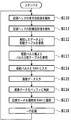
図14は、本発明の第二の実施形態による駆動信号波形制御の手順を示すフローチャートである。
【0063】
記録ヘッドの装着があると、まずステップS110で、ブロックごとにその装着された記録ヘッドの素子抵抗値を検出し、また、ステップS111で、同様にブロックごとに記録ヘッドの配線抵抗値を検出する。本実施形態では、これらの抵抗値は記録ヘッドに設けられたEEPROMに予め書込んでおき、これを読み出すことによって抵抗値の検出を行なうことができる。
【0064】
検出されたこれらの総抵抗値に基づき、ステップS112で、図15に示される、ROM164に格納されたヒータ抵抗-駆動パルステーブルを参照し、カラムにおける各ブロックについて駆動信号のパルス幅を求める。
【0065】
本実施形態では、総抵抗値は、80〜139Ωのいずれかとなる。図15のヒータ抵抗-駆動パルステーブルに示すように、総抵抗値が80〜89Ωのときは1.6μs、89〜99Ωのときは1.8μsというように、総抵抗値に応じてパルス幅が設定される。
【0066】
次に、ステップS113で、第一の実施形態と同様、上記で求めたパルス幅に基づき、図12に示す駆動パルス幅分割テーブルを参照し、各ブロックの駆動信号としてのダブルパルスを求める。
【0067】
そして、ステップS114において、ブロック毎のダブルパルスの波形データが、RAM165の設定パルス幅エリアcに書き込まれる。次に、実施形態1のステップS100〜S102と同様、まずステップS115で、画像データを画像入力部161を介して入力し、次に、ステップS116で、画像信号処理部166のデータバッファに一時的に格納した後、所定のタイミングで、画像処理部において輝度濃度変換、マスキング等、所定の画像処理を行い、最終的に2値化処理を行って2値の記録データを得る。そして、ステップS117において、この記録データはRAM165のデータ展開用エリアaに展開される。そして、ステップS118で、RAM165のパルス幅エリアcに格納されたパルス幅に従い一行分の記録を行う。
【0068】
本実施形態においても、第一実施形態と同様、安定したインクの吐出を行なうことができる。なお、本実施形態は、特開平9−11504号公報に記載の発明と組み合わせて、同時駆動するヒータ数をカウントし、駆動信号のパルス幅を求め、そのパルス幅を変更する形態で実施してもよい。
【0069】
【発明の効果】
以上の説明から明らかなように、本発明によれば、複数のヒータに駆動信号を供給するときの当該駆動信号の電圧降下の程度を示す量に応じて、駆動信号を単一パルスからダブルパルスの駆動信号に変更し、または、パルス波形を求めるので、さらには、分割パルスにおける先行するパルスの幅の比率を前記電圧降下の程度を示す量が少なくなるほど大きくなるように制御するので、単一パルスでヒータを駆動するときにそのパルス幅である通電時間が、吐出量が変動する範囲のものであるときは、それをダブルパルスまたは変更した別の波形のパルスでヒータを駆動することができ、これにより、吐出量が変動しない駆動信号によってインク吐出を行なうことが可能となる。
【0070】
この結果、記録ヘッドにおける複数のヒータを駆動する際、その駆動数などの電圧降下にかかる所定量の変化に応じてパルス幅を制御する場合に、その制御範囲を適切に定めることによって安定した吐出を行なうことができる。
【図面の簡単な説明】
【図1】記録ヘッドの駆動信号のパルス幅とそれによるインク吐出量との関係を示す線図である。
【図2】本発明の一実施形態にかかるインクジェットプリンタの機構部を示す斜視図である。
【図3】上記プリンタで用いられる記録ヘッドのノズル配列を示す正面図である。
【図4】上記プリンタで用いられる記録ヘッドカートリッジを示す斜視図である。
【図5】上記記録ヘッドカートリッジを構成する記録ヘッドとインクタンクとを相互に着脱した状態で示す斜視図である。
【図6】上記本実施形態に係るプリンタの制御構成を示すブロック図である。
【図7】上記プリンタにおける記録ヘッド駆動回路を示す回路図である。
【図8】上記回路における1つのブロックに関する各種データのタイミングチャートである。
【図9】上記回路における1つのカラムのブロックごとの各種データのタイミングチャートである。
【図10】本発明の第一の実施形態にかかる駆動信号のパルス波形制御の手順を示すフローチャートである。
【図11】上記第一の実施形態にかかる同時駆動ビット−駆動パルステーブルを示す模式図である。
【図12】上記第一の実施形態および本発明の第二実施形態にかかる駆動パルス幅分割テーブルを示す模式図である。
【図13】上記第一の実施形態および上記第二実施形態にかかるダブルパルスのパルス幅を説明するための波形図である。
【図14】上記第二の実施形態にかかる駆動信号のパルス波形制御の手順を示すフローチャートである。
【図15】上記第二実施形態にかかるヒータ抵抗−駆動パルステーブルを示す模式図である。
【符号の説明】
71 ヒータ(電気熱変換素子)
72 8ビットシフトレジスタ
73 4ビットシフトレジスタ
74 8ビットラッチ
75 4ビットラッチ
76 ドライバ
77 デコーダ
161 画像入力部
162 操作部
163 CPU
164 ROM
165 RAM
166 画像信号処理部
167 プリンタエンジン部
168 バスライン
170 同時駆動ビットカウンタ
H1000 記録ヘッドカートリッジ
H1001 記録ヘッド
H1900 インクタンク
M4001 キャリッジ[0001]
BACKGROUND OF THE INVENTION
The present invention relates to an ink jet recording apparatus and an ink jet recording method, and more specifically, the electrothermal conversion in a system in which bubbles are generated by applying thermal energy to ink using an electrothermal conversion element, and ink is ejected by the pressure of the bubbles. The present invention relates to element driving.
[0002]
[Prior art]
In recent years, recording apparatuses represented by printers have become widespread, and one tendency of such recording apparatuses is to enable high-speed recording, high-resolution recording, low-noise recording, and the like. An ink jet recording apparatus can be given as a recording apparatus that meets such a requirement. The ink jet system is a system in which ink (recording liquid) droplets are ejected and ejected from an ejection port of a recording head, and this is adhered to a recording medium for recording. As a result, the above-described high-speed recording or the like can be realized relatively easily, and the recording head and the recording medium perform recording in a non-contact manner. Is possible.
[0003]
Among such ink jet methods, a method of ejecting ink using heat energy generated by an electrothermal conversion element is a widely used method. In this method, an electrothermal conversion element (hereinafter referred to as “heater”) is used. Heat energy is generated by applying a drive signal of a predetermined voltage to both ends of the other.
[0004]
The heater and wiring electrodes for applying a voltage to the heater are formed on the substrate using the same technique as in the semiconductor manufacturing process, and the recording head is manufactured based on the heater. For this reason, for example, with respect to the heaters provided in each of the plurality of ejection ports of the recording head, the resistance value may vary due to manufacturing variations of the heating resistor film constituting each of the heaters. As a result, even if a constant voltage is applied to the plurality of heaters of the recording head, the current varies among the heaters according to the variation in the resistance value, resulting in a difference in the generated thermal energy. Depending on the ejection port, there may be a problem that ink is not ejected satisfactorily. Even if there is no variation among the plurality of heaters in one print head, there may be a variation between print heads.
[0005]
In order to solve such a problem, conventionally, at the time of manufacture, the resistance values of each of the plurality of heaters in the recording head are measured in advance, and the pulse width of the drive pulse supplied to the heater is set based on the measured resistance value. . In addition, the pulse width is set in consideration of not only the resistance value of the heater but also the resistance value of the wiring electrode.
[0006]
Incidentally, so-called time-division driving (or block driving) is known for driving a multi-nozzle head having a plurality of ejection openings (hereinafter also referred to as “nozzles”). For example, a method for recording ruled lines with the simplest control, which is a straight line along the direction in which the nozzles of the recording head are arranged, is to simultaneously eject from a plurality of nozzles of the recording head. However, when all the nozzles of the print head are driven simultaneously in this way, especially when the number of nozzles is large for high speed printing or high density, this causes a large voltage drop or a temporary common. In some cases, the level of negative pressure in the liquid chamber becomes high, and ink refilling to each nozzle may not be in time. Therefore, a time-division driving method is often employed in which a plurality of nozzles of the recording head are divided into several blocks, and driving is performed in a time-sharing manner for each block. According to this time-division driving method, the ink dots recorded by the ink ejected from each nozzle will be shifted for each block, but by adjusting the position of each nozzle in the recording head or tilting the nozzle row, etc. This shift is made as inconspicuous as possible.
[0007]
However, the number of nozzles may be several hundred to several thousand, and the driving frequency of each heater may be several tens of kHz depending on demands for higher-speed recording and high-resolution recording. In this case, the number of heaters that are driven simultaneously for each block increases, so that the instantaneous maximum current increases and the voltage drop of the power supply voltage due to the wiring electrodes and the like further increases. Of course, the number of heaters driven at the same time depends on the recording data. However, when there are a large number of heaters per block, it is necessary to discharge each heater due to the relatively large voltage drop described above. May cause a discharge failure such as non-discharge or an insufficient discharge amount.
[0008]
In order to solve this problem, it has been conventionally performed to increase the set voltage of the heater drive signal in order to reduce the wiring resistance as much as possible and to provide a margin for the maximum voltage drop.
[0009]
However, in the above-described method of increasing the set voltage, the voltage that can be withstood by the heater has a certain limit. Therefore, the set voltage cannot be simply increased as the number of heaters increases. In addition, when the number of heaters that are driven simultaneously is small depending on the recording data, excessive energy is input to the heaters, leading to a problem that the durability of the heaters is impaired as well as a decrease in thermal efficiency.
[0010]
In order to solve this problem, for example, as disclosed in JP-A-9-11504, there is known a method of controlling the pulse width and voltage value of a drive signal by counting the number of heaters that are simultaneously driven. This counts the number of heaters that are driven simultaneously, calculates a voltage drop based on this, and controls the pulse width and voltage value according to the drop. Thereby, it becomes possible to prevent the above-mentioned ejection failure. This method is effective with respect to thermal efficiency and durability of the heater because an appropriate pulse width or voltage value calculated based on the number of simultaneously driven heaters is set.
[0011]
However, control of the voltage value in this method is not practical. Compensation according to the voltage drop requires high-precision and high-speed voltage value control, and the voltage control power supply currently known is not only costly but also technically difficult. Because there is. For this reason, in the above method, it is common to compensate for the foaming energy corresponding to the voltage drop due to simultaneous driving by controlling the pulse width exclusively.
[0012]
[Problems to be solved by the invention]
As described above, the pulse width of the heater drive signal is controlled in order to solve the problem of ejection failure due to variations in wiring resistance related to heater drive and voltage drop due to simultaneous drive of a plurality of heaters.
[0013]
However, the above-described pulse width control leads to problems that the pulse width itself becomes large and cannot be adapted to the driving cycle, or that the pulse width control width becomes wide and the discharge amount and discharge speed fluctuate. There is a case.
[0014]
FIG. 1 is a diagram showing the relationship between the pulse width of the heater drive signal and the discharge amount. This relationship is that the driving signal is a rectangular single pulse, the voltage value of the pulse is constant, and the energy of the pulse that actually contributes to ejection after subtracting the voltage drop is constant regardless of the pulse width. It was obtained under the conditions. That is, the energy of the pulse has a constant ratio (greater than 1) with respect to the critical foaming critical energy that can cause foaming at any pulse width.
[0015]
As shown in FIG. 1, the ejection amount varies greatly in a region where the pulse width is relatively small. In any of the conventional pulse controls described above, this region that fluctuates greatly is not used, and the pulse width control is performed in the actual use region where the basic pulse width is increased and the discharge amount fluctuation is small. Thereby, even if the pulse width is changed by control, it is possible to prevent the discharge amount and the discharge speed from changing so much.
[0016]
However, in the case of further high-speed driving, the driving cycle becomes short, so that the pulse having a relatively long width does not fall within such a driving cycle, which may hinder the driving of the recording head. Further, in order to appropriately control the pulse width in response to a large voltage drop, the control width must be increased, and as a result, the control region includes a region where the ejection amount greatly varies as shown in FIG. May end up. Then, the discharge amount and the discharge speed vary due to the pulse width control, which causes a problem that the recording quality is remarkably deteriorated.
[0017]
The present invention has been made to solve such problems. The object of the present invention is to change the heater resistance and wiring resistance in the recording head and to change the voltage drop when driving a plurality of heaters simultaneously. The present invention provides an ink jet recording apparatus and an ink jet recording method capable of appropriately determining a control range when performing pulse width control according to the above and capable of performing stable ejection.
[0018]
[Means for Solving the Problems]
Therefore, in the present invention, an ink jet recording apparatus that performs recording by ejecting ink onto a recording medium using a recording head that ejects ink using thermal energy generated by supplying voltage pulses to each of a plurality of heaters. In accordance with the amount detected by the detection means, the detection means for detecting the amount indicating the degree of voltage drop of the voltage pulse when the voltage pulse is supplied to the plurality of heaters, Each other Of the double pulses composed of the first and second pulses spaced apart Precede And control means for controlling the width of the first pulse so that the width of the first pulse becomes longer as the amount indicating the degree of the voltage drop becomes smaller.
[0019]
In another embodiment, in an ink jet recording apparatus that uses a recording head that discharges ink using thermal energy generated by supplying voltage pulses to each of a plurality of heaters, and performs recording by discharging ink to a recording medium The plurality of heaters Voltage pulse Detecting means for detecting an amount indicating the degree of voltage drop of the voltage pulse when the voltage pulse is supplied, and the ratio of the width of the preceding pulse in the divided pulse as the voltage pulse according to the amount detected by the detecting means. And control means for controlling the voltage drop so as to increase as the amount indicating the degree of voltage drop decreases.
[0022]
Also, each of multiple heaters Voltage pulse In the ink jet recording method in which recording is performed by ejecting ink onto a recording medium using a recording head that ejects ink using thermal energy generated by supplying the plurality of heaters. Voltage pulse Supply when the concerned Voltage pulse Detecting an amount indicating the degree of voltage drop of, and depending on the amount detected by the detection step, Voltage pulse And a step of controlling the width of the preceding pulse in the divided pulse so as to increase as the amount indicating the degree of the voltage drop decreases.
[0023]
In another form, each of the heaters Voltage pulse In the ink jet recording method in which recording is performed by ejecting ink onto a recording medium using a recording head that ejects ink using thermal energy generated by supplying the plurality of heaters. Voltage pulse Supply when the concerned Voltage pulse Detecting an amount indicating the degree of voltage drop of, and depending on the amount detected by the detection step, Voltage pulse And a step of controlling the ratio of the width of the preceding pulse in the divided pulse so as to increase as the amount indicating the degree of the voltage drop decreases.
[0026]
According to the above configuration, the drive signal is changed from a single pulse to a double pulse drive signal according to the amount indicating the degree of voltage drop of the drive signal when the drive signal is supplied to a plurality of heaters, or Since the pulse waveform is obtained, the ratio of the width of the preceding pulse in the divided pulse is controlled so as to increase as the amount indicating the degree of the voltage drop decreases, so that when the heater is driven with a single pulse, When the energization time, which is the pulse width, is within the range where the discharge amount varies, the heater can be driven with a double pulse or a pulse with another waveform that is changed. Ink ejection can be performed by the drive signal that is not performed.
[0027]
DETAILED DESCRIPTION OF THE INVENTION
Hereinafter, embodiments of the present invention will be described in detail with reference to the drawings.
[0028]
FIG. 2 is a perspective view showing a main configuration of the ink jet printer according to the embodiment of the present invention.
[0029]
The printer of this embodiment uses four recording heads that eject black (K), cyan (C), magenta (M), and yellow (Y) inks, respectively. These recording heads and ink tanks are in the form of cartridges as will be described later with reference to FIGS. 4 and 5, and are used by being detachably mounted on the carriage M4001. FIG. 2 shows a state where the cartridge including the recording head and the ink tank is removed. As shown in FIG. 3, each recording head has 384 nozzles, and the nozzle arrangement density is 360 dpi.
[0030]
The above recording head is mounted on a carriage M4001 together with an ink tank, and each recording head is moved to a recording sheet (not shown) by moving the carriage M4001 by a driving force of a carriage motor (not shown) while being guided by a guide shaft. ), And ink is ejected onto the recording paper according to the recording data during the scanning. More specifically, the carriage M4001 located at the home position before the start of recording moves in the right direction (forward scanning direction) in the figure when a recording start command is issued. During this time, ink is ejected from the nozzles of each recording head in accordance with the recording data, and recording with a width corresponding to the nozzle row is performed on the recording paper. Ink is ejected from the recording head by driving a heater provided corresponding to each nozzle at a timing based on a position detection signal of an encoder that detects a moving position of the carriage. When the recording up to the end of the predetermined recording area on the recording paper is completed, the carriage M4001 returns to the home position, and similarly performs the above-described scanning in the forward scanning direction to perform recording. Alternatively, in the case of reciprocal recording, the same recording operation is performed in the backward scanning direction opposite to the upward air scanning. During these scans, the paper feed roller M3001 rotates a predetermined amount to feed the paper by the above width. By repeating scanning of the recording head and paper feeding in this manner, a predetermined image or the like can be recorded on the paper.
[0031]
M3001 is a paper feed roller that transports the recording paper fed from the automatic feeding device M3022 by an amount corresponding to the recording width by scanning of the recording head.
[0032]
The carriage M4001 moves to the home position located at the right end in the figure when not recording or when performing discharge recovery processing, etc., and waits for recording here, and can perform discharge recovery processing by the recovery unit M5000. .
[0033]
4 is a perspective view showing a print head cartridge used in the ink jet printer of the present embodiment shown in FIG. 2, and FIG. 5 shows the print head and ink tank constituting the print head cartridge removed from each other. It is a perspective view.
[0034]
As shown in these drawings, the recording head cartridge H1000 includes a recording head H1001 and an ink tank H1900 (H1900K, H1900C, H1900M, H1900Y) provided detachably with respect to the recording head H1001. That is, the ink tank H1900K contains black ink, the ink tank H1900C similarly contains cyan ink, the ink tank H1900M contains magenta ink, and the ink tank H1900Y contains yellow ink. Each of the ink tanks H1900K, H1900C, H1900M, and H1900Y is configured to be detachable from the recording head H1001, so that each ink tank can be individually replaced. As a result, the running cost for recording in the printer can be reduced.
[0035]
The recording head H1001 is integrally provided with mounting portions for mounting the respective ink tanks H1900. In these drawings, the discharge port surface on which the nozzle rows shown in FIG. 3 are arranged faces downward. .
[0036]
The recording head cartridge H1000 is detachably mounted on the carriage M4001 of the ink jet printer shown in FIG. 2, and when mounted, the recording head cartridge H1000 is mounted and positioned by a head set lever M4007 (see FIG. 2) provided on the carriage M4001. The operation is performed. In addition, by this mounting, the electrical contact board of the recording head cartridge H1000 and the electrical contact board of the carriage M4001 are connected and fixed to each other.
[0037]
FIG. 6 is a block diagram showing a control configuration of the ink jet printer according to the above-described embodiment, and particularly shows a control configuration of a drive signal in driving the recording head.
[0038]
In the figure, an
[0039]
The
[0040]
The image
[0041]
FIG. 7 is a circuit diagram illustrating a configuration of a head driving circuit configured in the recording head of the present embodiment.
[0042]
Each recording head of this embodiment is provided with 3 sets of the circuit shown in the figure, thereby dividing 384 electrothermal transducer elements (heaters) 71 into 16 blocks of 24 (8 × 3 sets). These heaters are driven in a time-sharing manner for each block. That is, in the present embodiment, each set of circuits is provided with a
[0043]
FIG. 8 is a timing chart showing transfer timings of recording data for one block and data indicating a drive block in one set of circuits.
[0044]
As shown in the figure, the signal DATA + BE is input from the DATA terminal (FIG. 7) in accordance with the edge timing of the clock signal CLK input to the CLK terminal (FIG. 7). As shown in the table of FIG. 8, among the signals DATA + BE, the recording data DATA0 to 7 input in the
[0045]
When the transfer of the recording data and the block selection data for one block is completed, the data in the
[0046]
FIG. 9 is a timing chart relating to heater driving for one column corresponding to the nozzle row of the recording head. That is, when the data transfer for one block described in FIG. 8 is completed, data transfer and heater driving are performed simultaneously from the next block. FIG. 9 shows this data transfer and heater driving. Is a timing chart for 16 blocks, that is, for one drive cycle.
[0047]
In FIG. 9, the block selection data latched in the 4-bit latch 75 in accordance with the LT signal is input to the decoder 77 (FIG. 7), and as shown in the table of FIG. The bit block enable data BLE0 to 15 are decoded and output. That is, as shown in the table of FIG. 9, the combination of L (0) or H (1), which is the content of each of the block selection data BE0 to BE3, sequentially changes for each transfer of the one block, and accordingly, Blocks that can be driven (block enable data BLE becomes H) are sequentially selected. Further, the heat enable signal HE is input from the HE terminal (FIG. 7) next to the latch signal LT described above. Here, the heat enable signal HE is active low.
[0048]
In the circuit shown in FIG. 7, the HE terminal is connected to all drivers. Further, all of the signal lines of the block enable data BLE0 to BLE are connected to the eight
[0049]
More specifically, the heat enable signal HE sets the pulse width of the heater drive signal. The recording data DATA and the heat enable signal HE are input to all 16 AND circuits (not shown) provided for each of the 16 heaters in each
[0050]
(Embodiment 1)
Next, drive signal control according to the first embodiment of the present invention in the inkjet printer of the present embodiment described above will be described below.
[0051]
FIG. 10 is a control flowchart during recording. 11 shows a simultaneous bit-drive pulse table in the
[0052]
First, from the recording standby state, in step S100, image data is input via the
[0053]
Next, in step S103, the simultaneous
[0054]
In the present embodiment, as described with reference to FIG. 7, the number of simultaneous drives for each block is 0 to 24 bits depending on the recording data. As shown in the simultaneous bit-drive pulse table of FIG. 11, the pulse width is obtained such that the pulse width is 1.6 μs when the number of simultaneous drives is 0 to 3 and 1.8 μs when the number of simultaneous drives is 4 to 7.
[0055]
This pulse width means that the heater drive signal is a predetermined voltage value V H The pulse width when the voltage pulse is a single pulse having a rectangular shape, that is, the energization time. As described above with reference to FIG. 1, when the heater is driven using such a single pulse, the discharge amount varies greatly in a region where the pulse width is short. In the range of 1.6 μs to 3.6 μs, the drive signal is changed to a so-called double pulse as shown below, so that the fluctuation of the discharge amount is not caused. It should be noted that the total energy of the double pulses obtained by the table of the present embodiment and the energy of the corresponding basic single pulse are the same for any pulse width, and as described above, each energy is actually The energy that contributes to ejection is equally equal to the critical foaming energy. In this case, the single pulse and the double pulse are equal and constant in the voltage value.
[0056]
After the above table reference, in the next step S105, the drive signal waveform of each block is set by referring to the drive pulse width division table of
[0057]
P1, P2, and P3 in FIG. 12 mean the widths of two divided pulses and the pause time between the two pulses, as shown in FIG. In the present embodiment, two rectangular pulses are used, but three or more rectangular pulses may be used as non-rectangular pulses. Thus, a plurality of pulses composed of a plurality of pulses include at least one pre-pulse (preceding pulse) that performs heating without foaming in the ink by the heating, a main pulse with foaming, and a pause period between those pulses. It is a waste. The single pulse is a single pulse for ejecting ink by foaming.
[0058]
As shown in the drive pulse division table of FIG. 12, when the pulse width is 1.6 μs, P1 (pre-pulse) = 0.7 μs, P2 (pause time) = 0.9 μs, P3 (main pulse) = 0.9 μs. When the pulse width is 1.8 μs, P1 (pre-pulse) = 0.5 μs, P2 (pause time) = 0.8 μs, P3 (main pulse) = 1.3 μs, and when the pulse width is 2.0 μs, When P1 (prepulse) = 0.4 μs, P2 (pause time) = 0.7 μs, P3 (main pulse) = 1.6 μs, and the pulse width is 2.5 μs, P1 (prepulse) = 0.3 μs, P2 ( Pause time) = 0.6 μs, P3 (main pulse) = 2.2 μs, and pulse width 3.0 μs, P1 (pre-pulse) = 0.2 μs, P2 (pause time) = 0.5 μs, P3 (main (Pulse) = 2.8μs, when the pulse width is 3.6μs, P1 (pre-pulse) 0.0μs, P2 (pause time) = 0.0μs, P3 (main pulse) = 3.6μs, and so on, the pulse width of the drive signal for each block is set. As is clear from this, the drive signal is a double pulse (multiple pulses) until the pulse width obtained based on the number of simultaneously driven bits is 3.0 μs, and the widths of the pre-pulse, the pause period, and the main pulse are different. However, when the required pulse width is 3.6 μs, the waveform itself becomes a single pulse by varying the widths. However, this can also be considered as a pre-pulse and a pause period of 0 μs in the double pulse.
[0059]
As seen from the relationship between the number of simultaneously driven bits and the pulse width, the smaller the number of simultaneously driven bits, the larger the prepulse width. In addition, the smaller the number of simultaneously driven bits, the higher the ratio of the prepulse width to the total pulse width of the prepulse width and the main pulse width (energization time corresponding to a single pulse width). Thus, stable ejection can be performed even when pulse width modulation is performed within a short pulse width range.
[0060]
After the above waveform setting, in step S106, the pulse width of the drive signal set for each block of one column is written in the set pulse width area c of the
[0061]
As described above, according to the present embodiment, by changing the single pulse obtained based on the number of simultaneously driven bits of one block to a double pulse, the number of simultaneously driven signals can be appropriately set in the case of a single pulse. It is possible to prevent the adverse effect of the pulse control width becoming too large when it corresponds and the adverse effect that the pulse width obtained by the pulse width control enters the unstable ejection region.
[0062]
(Embodiment 2)
FIG. 14 is a flowchart showing a procedure of drive signal waveform control according to the second embodiment of the present invention.
[0063]
When the recording head is mounted, first, in step S110, the element resistance value of the mounted recording head is detected for each block. In step S111, the wiring resistance value of the recording head is similarly detected for each block. . In this embodiment, these resistance values are written in advance in an EEPROM provided in the recording head, and the resistance values can be detected by reading them out.
[0064]
Based on these detected total resistance values, in step S112, the heater resistance-drive pulse table stored in the
[0065]
In the present embodiment, the total resistance value is 80 to 139Ω. As shown in the heater resistance-driving pulse table of FIG. 15, the pulse width depends on the total resistance value, such as 1.6 μs when the total resistance value is 80 to 89Ω and 1.8 μs when the total resistance value is 89 to 99Ω. Is set.
[0066]
Next, in step S113, as in the first embodiment, the double pulse as the drive signal of each block is obtained by referring to the drive pulse width division table shown in FIG.
[0067]
In step S114, the double-pulse waveform data for each block is written in the set pulse width area c of the
[0068]
Also in the present embodiment, as in the first embodiment, stable ink ejection can be performed. In addition, this embodiment is implemented in combination with the invention described in Japanese Patent Application Laid-Open No. 9-11504 by counting the number of heaters that are driven simultaneously, obtaining the pulse width of the drive signal, and changing the pulse width. Also good.
[0069]
【The invention's effect】
As is clear from the above description, according to the present invention, the drive signal is changed from a single pulse to a double pulse according to the amount indicating the degree of voltage drop of the drive signal when the drive signal is supplied to a plurality of heaters. Or the pulse waveform is obtained, and further, the ratio of the width of the preceding pulse in the divided pulse is controlled so as to increase as the amount indicating the degree of the voltage drop decreases. If the energizing time, which is the pulse width when driving the heater with a pulse, is within a range where the discharge amount varies, the heater can be driven with a double pulse or a pulse with another waveform that is changed. As a result, ink can be ejected by a drive signal whose ejection amount does not vary.
[0070]
As a result, when driving a plurality of heaters in the print head, when controlling the pulse width in accordance with a predetermined amount of change in voltage drop, such as the number of drives, stable ejection is achieved by appropriately determining the control range. Can be performed.
[Brief description of the drawings]
FIG. 1 is a diagram illustrating a relationship between a pulse width of a driving signal for a recording head and an ink discharge amount according to the pulse width.
FIG. 2 is a perspective view showing a mechanism part of the ink jet printer according to the embodiment of the present invention.
FIG. 3 is a front view showing a nozzle arrangement of a recording head used in the printer.
FIG. 4 is a perspective view showing a recording head cartridge used in the printer.
FIG. 5 is a perspective view showing a state where a recording head and an ink tank constituting the recording head cartridge are attached to and detached from each other.
FIG. 6 is a block diagram illustrating a control configuration of the printer according to the embodiment.
FIG. 7 is a circuit diagram showing a recording head drive circuit in the printer.
FIG. 8 is a timing chart of various data related to one block in the circuit.
FIG. 9 is a timing chart of various data for each block of one column in the circuit.
FIG. 10 is a flowchart showing a procedure of pulse waveform control of a drive signal according to the first embodiment of the present invention.
FIG. 11 is a schematic diagram showing a simultaneous drive bit-drive pulse table according to the first embodiment.
FIG. 12 is a schematic diagram showing a drive pulse width division table according to the first embodiment and the second embodiment of the present invention.
FIG. 13 is a waveform diagram for explaining a pulse width of a double pulse according to the first embodiment and the second embodiment.
FIG. 14 is a flowchart showing a procedure of pulse waveform control of a drive signal according to the second embodiment.
FIG. 15 is a schematic diagram showing a heater resistance-driving pulse table according to the second embodiment.
[Explanation of symbols]
71 Heater (electrothermal transducer)
72 8-bit shift register
73 4-bit shift register
74 8-bit latch
75 4-bit latch
76 drivers
77 Decoder
161 Image input unit
162 Operation unit
163 CPU
164 ROM
165 RAM
166 Image signal processor
167 Printer Engine
168 Bus line
170 Simultaneously driven bit counter
H1000 recording head cartridge
H1001 Recording head
H1900 ink tank
M4001 Carriage
Claims (10)
前記複数のヒータに電圧パルスを供給するときの当該電圧パルスの電圧降下の程度を示す量を検出する検出手段と、
該検出手段が検出した量に応じて、互いに間隔をおいた第1パルスと第2パルスとで構成されるダブルパルスのうちの先行する前記第1パルスの幅を前記電圧降下の程度を示す量が少なくなるほど長くなるように制御する制御手段と、
を備えたことを特徴とするインクジェット記録装置。In an inkjet recording apparatus that performs recording by ejecting ink onto a recording medium using a recording head that ejects ink using thermal energy generated by supplying voltage pulses to each of a plurality of heaters.
Detecting means for detecting an amount indicating a degree of voltage drop of the voltage pulse when the voltage pulse is supplied to the plurality of heaters;
An amount indicating the degree of the voltage drop in the width of the preceding first pulse of the double pulse composed of the first pulse and the second pulse spaced apart from each other according to the amount detected by the detecting means Control means for controlling the length to become longer as the number decreases,
An ink jet recording apparatus comprising:
前記複数のヒータに電圧パルスを供給するときの当該電圧パルスの電圧降下の程度を示す量を検出する検出手段と、
該検出手段が検出した量に応じて、前記電圧パルスとしての分割パルスにおける先行するパルスの幅の比率を前記電圧降下の程度を示す量が少なくなるほど大きくなるように制御する制御手段と、
を備えたことを特徴とするインクジェット記録装置。In an inkjet recording apparatus that performs recording by ejecting ink onto a recording medium using a recording head that ejects ink using thermal energy generated by supplying voltage pulses to each of a plurality of heaters.
Detecting means for detecting an amount indicating a degree of voltage drop of the voltage pulse when the voltage pulse is supplied to the plurality of heaters;
Control means for controlling the ratio of the width of the preceding pulse in the divided pulse as the voltage pulse so as to decrease as the amount indicating the degree of the voltage drop decreases according to the amount detected by the detecting means;
An ink jet recording apparatus comprising:
前記複数のヒータに電圧パルスを供給するときの当該電圧パルスの電圧降下の程度を示す量を検出し、該検出ステップが検出した量に応じて、前記電圧パルスとしての分割パルスにおける先行するパルスの幅を前記電圧降下の程度を示す量が少なくなるほど長くなるように制御する、ステップを有したことを特徴とするインクジェット記録方法。In an inkjet recording method in which recording is performed by ejecting ink onto a recording medium using a recording head that ejects ink using thermal energy generated by supplying voltage pulses to each of a plurality of heaters.
An amount indicating the degree of voltage drop of the voltage pulse when the voltage pulse is supplied to the plurality of heaters is detected, and according to the amount detected by the detection step, the preceding pulse in the divided pulse as the voltage pulse is detected. An ink jet recording method comprising a step of controlling the width so that the width becomes longer as the amount indicating the degree of voltage drop decreases.
前記複数のヒータに電圧パルスを供給するときの当該電圧パルスの電圧降下の程度を示す量を検出し、該検出ステップが検出した量に応じて、前記電圧パルスとしての分割パルスにおける先行するパルスの幅の比率を前記電圧降下の程度を示す量が少なくなるほど大きくなるように制御する、ステップを有したことを特徴とするインクジェット記録方法。In an inkjet recording method in which recording is performed by ejecting ink onto a recording medium using a recording head that ejects ink using thermal energy generated by supplying voltage pulses to each of a plurality of heaters.
An amount indicating the degree of voltage drop of the voltage pulse when the voltage pulse is supplied to the plurality of heaters is detected, and according to the amount detected by the detection step, the preceding pulse in the divided pulse as the voltage pulse is detected. An ink jet recording method comprising: a step of controlling the width ratio so that the width ratio increases as the amount indicating the degree of voltage drop decreases.
Priority Applications (1)
| Application Number | Priority Date | Filing Date | Title |
|---|---|---|---|
| JP2001303437A JP4780882B2 (en) | 2000-09-29 | 2001-09-28 | Inkjet recording apparatus and inkjet recording method |
Applications Claiming Priority (4)
| Application Number | Priority Date | Filing Date | Title |
|---|---|---|---|
| JP2000-301096 | 2000-09-29 | ||
| JP2000301096 | 2000-09-29 | ||
| JP2000301096 | 2000-09-29 | ||
| JP2001303437A JP4780882B2 (en) | 2000-09-29 | 2001-09-28 | Inkjet recording apparatus and inkjet recording method |
Publications (3)
| Publication Number | Publication Date |
|---|---|
| JP2002172784A JP2002172784A (en) | 2002-06-18 |
| JP2002172784A5 JP2002172784A5 (en) | 2008-11-13 |
| JP4780882B2 true JP4780882B2 (en) | 2011-09-28 |
Family
ID=26601280
Family Applications (1)
| Application Number | Title | Priority Date | Filing Date |
|---|---|---|---|
| JP2001303437A Expired - Fee Related JP4780882B2 (en) | 2000-09-29 | 2001-09-28 | Inkjet recording apparatus and inkjet recording method |
Country Status (1)
| Country | Link |
|---|---|
| JP (1) | JP4780882B2 (en) |
Families Citing this family (3)
| Publication number | Priority date | Publication date | Assignee | Title |
|---|---|---|---|---|
| JP2006239861A (en) * | 2005-02-28 | 2006-09-14 | Sii Printek Inc | Inkjet printer device |
| JP5863192B2 (en) * | 2013-01-29 | 2016-02-16 | 京セラドキュメントソリューションズ株式会社 | Inkjet recording device |
| JP7129256B2 (en) * | 2018-07-19 | 2022-09-01 | キヤノン株式会社 | Recording device and control method |
Family Cites Families (1)
| Publication number | Priority date | Publication date | Assignee | Title |
|---|---|---|---|---|
| JPH0911463A (en) * | 1995-06-28 | 1997-01-14 | Fuji Xerox Co Ltd | Ink-jet recording device, its driving device, and ink-jet recording method |
-
2001
- 2001-09-28 JP JP2001303437A patent/JP4780882B2/en not_active Expired - Fee Related
Also Published As
| Publication number | Publication date |
|---|---|
| JP2002172784A (en) | 2002-06-18 |
Similar Documents
| Publication | Publication Date | Title |
|---|---|---|
| EP1193065B1 (en) | Ink jet printing apparatus and ink jet printing method | |
| EP0390202B1 (en) | Ink jet recording head, driving method for same and ink jet recording apparatus | |
| EP1150245B1 (en) | Ink jet printing method for optimizing image-element edges | |
| KR100994618B1 (en) | Head substrate, printhead, head cartridge, and printing apparatus | |
| US6193351B1 (en) | System to perform ink jet printing head recovery | |
| JPH03227636A (en) | Liquid jet recorder | |
| JP3133869B2 (en) | INK JET RECORDING APPARATUS AND DISCHARGE RECOVERY METHOD OF INK JET RECORDING APPARATUS | |
| JPH07241992A (en) | Recording head, method and device for recording with such recording head | |
| KR100435011B1 (en) | Printing apparatus and printing control method | |
| JP4266588B2 (en) | Recording apparatus and recording control method | |
| JP4780882B2 (en) | Inkjet recording apparatus and inkjet recording method | |
| JPH06246931A (en) | Ink jet device | |
| JPH09207358A (en) | Ink jet recording method and device therefor | |
| JP4585660B2 (en) | Inkjet printing apparatus and inkjet printing method | |
| JP2003089196A (en) | Ink jet recorder and its ink temperature controlling method | |
| US8096631B2 (en) | Ink-jet type image-forming apparatus and ink-jet type image-forming method | |
| EP0897804A2 (en) | Liquid ink printhead | |
| JPH10109409A (en) | Ink jet recording apparatus and control method thereof | |
| JP3159897B2 (en) | Recording device and recording method | |
| JP2006289624A (en) | Recorder and control method of recorder | |
| JPH03218841A (en) | Ink jet recording device | |
| JP4455013B2 (en) | Recording head driving method, recording head, and recording apparatus | |
| JP2004188942A (en) | Inkjet recorder | |
| JP2006168105A (en) | Inkjet printing head controlling apparatus | |
| JP5230093B2 (en) | Element substrate, recording head, recording apparatus |
Legal Events
| Date | Code | Title | Description |
|---|---|---|---|
| A521 | Request for written amendment filed |
Free format text: JAPANESE INTERMEDIATE CODE: A523 Effective date: 20080929 |
|
| A621 | Written request for application examination |
Free format text: JAPANESE INTERMEDIATE CODE: A621 Effective date: 20080929 |
|
| RD02 | Notification of acceptance of power of attorney |
Free format text: JAPANESE INTERMEDIATE CODE: A7422 Effective date: 20101106 |
|
| A977 | Report on retrieval |
Free format text: JAPANESE INTERMEDIATE CODE: A971007 Effective date: 20110328 |
|
| A131 | Notification of reasons for refusal |
Free format text: JAPANESE INTERMEDIATE CODE: A131 Effective date: 20110415 |
|
| A521 | Request for written amendment filed |
Free format text: JAPANESE INTERMEDIATE CODE: A523 Effective date: 20110614 |
|
| TRDD | Decision of grant or rejection written | ||
| A01 | Written decision to grant a patent or to grant a registration (utility model) |
Free format text: JAPANESE INTERMEDIATE CODE: A01 Effective date: 20110701 |
|
| A01 | Written decision to grant a patent or to grant a registration (utility model) |
Free format text: JAPANESE INTERMEDIATE CODE: A01 |
|
| A61 | First payment of annual fees (during grant procedure) |
Free format text: JAPANESE INTERMEDIATE CODE: A61 Effective date: 20110705 |
|
| FPAY | Renewal fee payment (event date is renewal date of database) |
Free format text: PAYMENT UNTIL: 20140715 Year of fee payment: 3 |
|
| R151 | Written notification of patent or utility model registration |
Ref document number: 4780882 Country of ref document: JP Free format text: JAPANESE INTERMEDIATE CODE: R151 |
|
| FPAY | Renewal fee payment (event date is renewal date of database) |
Free format text: PAYMENT UNTIL: 20140715 Year of fee payment: 3 |
|
| LAPS | Cancellation because of no payment of annual fees |