JP6505706B2 - Exchange of rich communication suite capability information in communication system - Google Patents
Exchange of rich communication suite capability information in communication system Download PDFInfo
- Publication number
- JP6505706B2 JP6505706B2 JP2016536334A JP2016536334A JP6505706B2 JP 6505706 B2 JP6505706 B2 JP 6505706B2 JP 2016536334 A JP2016536334 A JP 2016536334A JP 2016536334 A JP2016536334 A JP 2016536334A JP 6505706 B2 JP6505706 B2 JP 6505706B2
- Authority
- JP
- Japan
- Prior art keywords
- client device
- ims
- sip
- user
- capability information
- Prior art date
- Legal status (The legal status is an assumption and is not a legal conclusion. Google has not performed a legal analysis and makes no representation as to the accuracy of the status listed.)
- Active
Links
Images


Classifications
-
- H—ELECTRICITY
- H04—ELECTRIC COMMUNICATION TECHNIQUE
- H04W—WIRELESS COMMUNICATION NETWORKS
- H04W60/00—Affiliation to network, e.g. registration; Terminating affiliation with the network, e.g. de-registration
-
- H—ELECTRICITY
- H04—ELECTRIC COMMUNICATION TECHNIQUE
- H04L—TRANSMISSION OF DIGITAL INFORMATION, e.g. TELEGRAPHIC COMMUNICATION
- H04L65/00—Network arrangements, protocols or services for supporting real-time applications in data packet communication
- H04L65/1066—Session management
- H04L65/1083—In-session procedures
- H04L65/1094—Inter-user-equipment sessions transfer or sharing
-
- H—ELECTRICITY
- H04—ELECTRIC COMMUNICATION TECHNIQUE
- H04L—TRANSMISSION OF DIGITAL INFORMATION, e.g. TELEGRAPHIC COMMUNICATION
- H04L65/00—Network arrangements, protocols or services for supporting real-time applications in data packet communication
- H04L65/10—Architectures or entities
- H04L65/1016—IP multimedia subsystem [IMS]
-
- H—ELECTRICITY
- H04—ELECTRIC COMMUNICATION TECHNIQUE
- H04L—TRANSMISSION OF DIGITAL INFORMATION, e.g. TELEGRAPHIC COMMUNICATION
- H04L65/00—Network arrangements, protocols or services for supporting real-time applications in data packet communication
- H04L65/1066—Session management
- H04L65/1101—Session protocols
- H04L65/1104—Session initiation protocol [SIP]
-
- H—ELECTRICITY
- H04—ELECTRIC COMMUNICATION TECHNIQUE
- H04L—TRANSMISSION OF DIGITAL INFORMATION, e.g. TELEGRAPHIC COMMUNICATION
- H04L65/00—Network arrangements, protocols or services for supporting real-time applications in data packet communication
- H04L65/10—Architectures or entities
- H04L65/1063—Application servers providing network services
Landscapes
- Engineering & Computer Science (AREA)
- Multimedia (AREA)
- Computer Networks & Wireless Communication (AREA)
- Signal Processing (AREA)
- Business, Economics & Management (AREA)
- General Business, Economics & Management (AREA)
- Mobile Radio Communication Systems (AREA)
- Telephonic Communication Services (AREA)
Description
本発明の実施形態は、通信システムにおけるリッチコミュニケーションスイート(RCS:Rich Communication Suite)能力情報を交換することに関する。 Embodiments of the present invention relate to exchanging Rich Communication Suite (RCS) capability information in a communication system.
ワイヤレス通信システムは、第1世代アナログワイヤレス電話サービス(1G)、第2世代(2G)デジタルワイヤレス電話サービス(暫定の2.5Gおよび2.75Gネットワークを含む)、第3世代(3G)および第4世代(4G)高速データ/インターネット対応ワイヤレスサービスを含む、様々な世代を通じて発展してきた。現在、セルラーシステムおよびパーソナル通信サービス(PCS)システムを含む、多くの様々なタイプのワイヤレス通信システムが使用されている。知られているセルラーシステムの例には、セルラーAnalog Advanced Mobile Phone System(AMPS)、および、符号分割多元接続(CDMA)、周波数分割多元接続(FDMA)、時分割多元接続(TDMA)、TDMAのGlobal System for Mobile access(GSM(登録商標))変形に基づくデジタルセルラーシステム、および、TDMA技術とCDMA技術の両方を使用するより新しいハイブリッドデジタル通信システムがある。 Wireless communication systems include first generation analog wireless telephone service (1G), second generation (2G) digital wireless telephone service (including provisional 2.5G and 2.75G networks), third generation (3G) and fourth generation (4G) 4G) has evolved through various generations, including high speed data / Internet enabled wireless services. Currently, many different types of wireless communication systems are used, including cellular systems and personal communication services (PCS) systems. Examples of known cellular systems include Cellular Analog Advanced Mobile Phone System (AMPS) and Code Division Multiple Access (CDMA), Frequency Division Multiple Access (FDMA), Time Division Multiple Access (TDMA), Global TDMA There is a digital cellular system based on the System for Mobile access (GSM (R)) variant and a newer hybrid digital communication system using both TDMA and CDMA techniques.
つい最近、モバイル電話および他のデータ端末の高速データのワイヤレス通信用のワイヤレス通信プロトコルとして、ロングタームエボリューション(LTE)が開発されてきている。LTEは、GSM(登録商標)に基づいており、GSM(登録商標)進化型高速データレート(EDGE)などの様々なGSM(登録商標)関連のプロトコル、および高速パケットアクセス(HSPA)などのユニバーサルモバイル通信システム(UMTS)プロトコルからの寄与を含む。 Most recently, Long Term Evolution (LTE) has been developed as a wireless communication protocol for high speed data wireless communication of mobile phones and other data terminals. LTE is based on GSM (R), and various GSM (R) related protocols such as GSM (R) Evolved High Data Rate (EDGE), and Universal Mobiles such as High Speed Packet Access (HSPA) Includes contributions from the communication system (UMTS) protocol.
種々の通信プロトコルを用いるアクセスネットワーク(たとえば、W-CDMA、LTEなどの3GPPアクセスネットワーク、またはWiFi、WLANまたは有線LANなどの非3GPPアクセスネットワーク)は、事業者(たとえば、Verizon、Sprint、AT&Tなど)によって管理されるIMSネットワークによるインターネットプロトコル(IP)マルチメディアサブシステム(IMS)サービスを、通信システムを介してユーザに提供するように構成することができる。IMSサービスを要求するためにIMSネットワークにアクセスするユーザは、要求されたIMSサービスをサポートするための複数の地域アプリケーションサーバまたはアプリケーションサーバクラスタ(たとえば、同じクラスタ地域にサービスを提供するアプリケーションサーバ群)のうちの1つに割り当てられる。 Access networks using various communication protocols (eg, W-CDMA, 3GPP access networks such as LTE, or non-3GPP access networks such as WiFi, WLAN or wired LAN) are operators (eg, Verizon, Sprint, AT & T, etc.) An Internet Protocol (IP) Multimedia Subsystem (IMS) service according to an IMS network managed by can be configured to provide the user via the communication system. A user accessing an IMS network to request IMS services may have multiple regional application servers or application server clusters (eg, an application server group serving the same cluster region) to support the requested IMS services. Assigned to one of them.
リッチコミュニケーションスイート(RCS)は、IMSドメインにおいて最近になって開発されたサービスタイプである。RCSによってユーザがその問合せ先にデバイス能力および/またはアプリケーションレベルマルチメディア能力を照会できるようになり、それにより、クライアントデバイスが、そのアドレス帳内の問合せ先の能力をリアルタイムで更新することができ、それにより、問合せ先のリアルタイム能力に基づいて、ボイスオーバLTE(VoLTE)、ビデオ通話、インスタントメッセージング(IM)、ファイルまたは画像共有などの「リッチコミュニケーション」を可能にする。現在のRCS規格では、ユーザ機器(UE)(または、クライアントデバイス)が、ターゲットUEのUE特有RCS能力を要求するために、1つまたは複数のターゲットUEにUE-UE間(または、ピアツーピア)セッション開始プロトコル(SIP:Session Initiation Protocol)OPTIONSメッセージを送る。SIP OPTIONSメッセージは、送信側UEのRCS能力を含み、SIP OPTIONSメッセージは、ターゲットUEに、ターゲットUEのRCS能力を指示するSIP 200 OKメッセージをもって、SIP OPTIONSメッセージに応答するように促す。したがって、SIP OPTIONSメッセージおよびSIP 200 OKメッセージの交換は、ピアツーピアハンドシェイキングプロセスであり、そのプロセスはIMSネットワークによって仲介され、そのプロセスによって、両方の終点が他方の終点のためのそれぞれのRCS能力を更新する。
Rich Communication Suite (RCS) is a recently developed service type in the IMS domain. RCS allows the user to query device capabilities and / or application level multimedia capabilities at the contact, allowing client devices to update the capabilities of the contact in their address book in real time. It enables "rich communication" such as voice over LTE (VoLTE), video calling, instant messaging (IM), file or image sharing etc. based on the real-time capabilities of the referee. In the current RCS standard, a user equipment (UE) (or client device) can perform UE-UE (or peer-to-peer) sessions with one or more target UEs to request UE-specific RCS capabilities of the target UEs. Sends Session Initiation Protocol (SIP) OPTIONS messages. The SIP OPTIONS message includes the RCS capabilities of the transmitting UE, and the SIP OPTIONS message prompts the target UE to respond to the SIP OPTIONS message with a
たとえば、UE1がIMSネットワークを介してUE2にSIP OPTIONSメッセージを送ることができ、そのメッセージは、UE1のRCS能力を指示し、UE2のRCS能力の指示をもってUE1に応答するようにUE2に要求し、UE1はIMSネットワークを介してUE3にSIP OPTIONSメッセージを送ることができ、そのメッセージは、UE1のRCS能力を指示し、UE3のRCS能力の指示をもってUE1に応答するようにUE3に要求し、他も同様である。その際、UE2は、UE1からのSIP OPTIONSメッセージに対して、UE2のRCS能力を指示するSIP 200 OKメッセージをもって応答し、UE3は、UE1からのSIP OPTIONSメッセージに対して、UE3のRCS能力を指示するSIP 200 OKメッセージをもって応答し、他も同様である。
For example, UE1 can send a SIP OPTIONS message to UE2 via the IMS network, which indicates the RCS capabilities of UE1 and requests UE2 to respond to UE1 with an indication of the RCS capabilities of UE2, UE 1 may send a SIP OPTIONS message to UE 3 via the IMS network, which indicates the RCS capabilities of UE 1 and requests UE 3 to respond to UE 1 with an indication of RCS capabilities of UE 3 and others It is similar. At that time, UE2 responds to the SIP OPTIONS message from UE1 with a
現在のIMS規格では、様々なUE(たとえば、セルフォン、タブレットコンピュータ、デスクトップコンピュータなど)は、IMSサービスを求めて同じユーザに登録され得る。しかしながら、現在のIMS規格では、別のUEと同じユーザに登録されたUEは、他のUEを一意にアドレス指定するための連絡先情報を必ずしも有するとは限らない。 In current IMS standards, various UEs (eg, cell phones, tablet computers, desktop computers, etc.) may be registered with the same user for IMS service. However, in the current IMS standard, a UE registered with the same user as another UE does not necessarily have contact information for uniquely addressing the other UE.
一実施形態では、第1のユーザに関連付けられたクライアントデバイスは、インターネットプロトコル(IP)マルチメディアサブシステム(IMS)サービスを求めて第1のユーザにクライアントデバイスを登録するためにIMSネットワークを用いて登録プロシージャを実行する。クライアントデバイスは、1つまたは複数の他のクライアントデバイスに関するリッチコミュニケーションスイート(RCS)能力情報を取得するためにIMSサービスを求めて第1のユーザに同様に登録された1つまたは複数の他のクライアントデバイスと(たとえば、GRUUを介して)通信する。クライアントデバイスは、クライアントデバイスのRCS能力情報を報告することを求める要求(たとえば、SIP OPTIONSメッセージ)を受信し、次いで、その受信した要求に応答して、(i)そのクライアントデバイスのRCS能力情報と(ii)1つまたは複数の他のクライアントデバイスに関するRCS能力情報の両方を示すメッセージ(たとえば、SIP 200 OKメッセージ)を送信する。
In one embodiment, the client device associated with the first user uses the IMS network to register the client device with the first user for Internet Protocol (IP) Multimedia Subsystem (IMS) service. Execute the registration procedure. The client device is one or more other clients also registered with the first user for IMS service to obtain rich communication suite (RCS) capability information for one or more other client devices Communicate with the device (eg, via GRUU). The client device receives a request (e.g., a SIP OPTIONS message) for reporting the client device's RCS capability information, and then, in response to the received request, (i) (ii) Send a message (eg, a
本発明の実施形態のより完全な理解、およびその付随する利点の多くは、以下の詳細な説明を添付の図面と併せ読んでよりよく理解すると、容易に得られる。添付の図面は、単に説明のために提示されているにすぎず、本発明を限定するものではない。 A more complete understanding of the embodiments of the present invention, and many of the attendant advantages thereof, will be readily obtained as the same becomes better understood when the following detailed description is read in conjunction with the accompanying drawings. The accompanying drawings are presented for the purpose of illustration only and are not intended to limit the present invention.
本発明の特定の実施形態を対象とする以下の説明および関連する図面において、本発明の態様が開示される。本発明の範囲から逸脱することなく、代替の実施形態が考案され得る。さらに、本発明の関連する詳細を不明瞭にしないように、本発明のよく知られている要素は詳細に説明されないか、または省略される。 Aspects of the invention are disclosed in the following description and related drawings directed to specific embodiments of the invention. Alternate embodiments may be devised without departing from the scope of the present invention. Additionally, well-known elements of the invention will not be described in detail or will be omitted so as not to obscure the relevant details of the invention.
「例示的」および/または「例」という言葉は、本明細書では「例、事例、または例示として機能すること」を意味するために使用される。本明細書で「例示的」および/または「例」として説明するいかなる実施形態も、必ずしも他の実施形態よりも好ましいまたは有利であると解釈されるべきではない。同様に、「本発明の実施形態」という用語は、本発明のすべての実施形態が、論じられた特徴、利点、または動作モードを含むことを必要としない。 The words "exemplary" and / or "example" are used herein to mean "serving as an example, instance, or illustration." Any embodiment described herein as "exemplary" and / or "example" should not necessarily be construed as preferred or advantageous over other embodiments. Similarly, the term "embodiment of the invention" does not require that all embodiments of the invention include the discussed feature, advantage or mode of operation.
さらに、多くの実施形態について、たとえばコンピューティングデバイスの要素によって実行されるべき、一連の動作に関して説明する。本明細書で説明する様々な動作は、特定の回路(たとえば、特定用途向け集積回路(ASIC))によって、1つもしくは複数のプロセッサによって実行されるプログラム命令によって、または両方の組合せによって実施され得ることを認識されよう。加えて、本明細書で説明するこれらの一連の動作は、実行時に、関連するプロセッサに本明細書で説明する機能を実施させるコンピュータ命令の対応するセットを記憶した、任意の形式のコンピュータ可読記憶媒体内で完全に具現化されるものと見なされ得る。したがって、本発明の様々な態様は、請求する主題の範囲内にすべて入ることが企図されているいくつかの異なる形式で具現化され得る。さらに、本明細書で説明する実施形態ごとに、任意のそのような実施形態の対応する形式について、本明細書では、たとえば、記載の動作を実行する「ように構成された論理」として説明することがある。 Furthermore, many embodiments are described, for example, in the context of a series of acts to be performed by an element of a computing device. The various operations described herein may be performed by specific circuits (eg, application specific integrated circuits (ASICs)), by program instructions executed by one or more processors, or by a combination of both. It will be recognized. In addition, these sequences of operations described herein may, when executed, store any corresponding set of computer instructions that cause the associated processor to perform the functions described herein. It can be considered to be fully embodied in the medium. Thus, the various aspects of the invention may be embodied in several different forms, all of which are intended to fall within the scope of the claimed subject matter. Further, for each of the embodiments described herein, the corresponding form of any such embodiment is described herein as, for example, "configured logic" to perform the described operations. Sometimes.
本明細書ではユーザ機器(UE)と呼ばれるクライアントデバイスは、モバイルであるか、または固定されている可能性があり、無線アクセスネットワーク(RAN)と通信し得る。本明細書で使用する「UE」という用語は、「アクセス端末」または「AT」、「ワイヤレスデバイス」、「加入者デバイス」、「加入者端末」、「加入者局」、「ユーザ端末」または「UT」、「モバイル端末」、「移動局」、およびそれらの変形形態と互換的に参照され得る。一般に、UEは、RANを介してコアネットワークと通信する可能性があり、コアネットワークを介してインターネットなどの外部ネットワークに接続され得る。当然、UEには、有線アクセスネットワーク、(たとえば、IEEE 802.11などに基づく)WiFiネットワークなどの、コアネットワークおよび/またはインターネットに接続する他の機構も考えられる。UEは、限定はしないが、PCカード、コンパクトフラッシュ(登録商標)デバイス、外付けもしくは内蔵のモデム、またはワイヤレスもしくは有線の電話などを含むいくつかのタイプのデバイスのうちの任意のものによって具体化され得る。UEが信号をRANに送信し得る通信リンクは、アップリンクチャネル(たとえば、逆方向トラフィックチャネル、逆方向制御チャネル、アクセスチャネルなど)と呼ばれる。RANが信号をUEに送信し得る通信リンクは、ダウンリンクチャネルまたは順方向リンクチャネル(たとえば、ページングチャネル、制御チャネル、ブロードキャストチャネル、順方向トラフィックチャネルなど)と呼ばれる。本明細書で使用される場合、トラフィックチャネル(TCH)という用語は、アップリンク/逆方向トラフィックチャネル、またはダウンリンク/順方向トラフィックチャネルのいずれかを指し得る。 A client device, referred to herein as a user equipment (UE), may be mobile or fixed and may communicate with a radio access network (RAN). The term "UE" as used herein refers to "access terminal" or "AT", "wireless device", "subscriber device", "subscriber terminal", "subscriber station", "user terminal" or Reference may be made interchangeably to “UT”, “mobile terminal”, “mobile station” and variants thereof. In general, the UE may communicate with the core network via the RAN, and may be connected to an external network such as the Internet via the core network. Of course, the UE may also consider other mechanisms to connect to the core network and / or the Internet, such as a wired access network, a WiFi network (e.g. based on IEEE 802.11 etc). A UE may be embodied by any of several types of devices including but not limited to PC card, Compact Flash® device, external or internal modem, or wireless or wired telephones etc. It can be done. The communication link over which the UE may send signals to the RAN is called an uplink channel (eg, a reverse traffic channel, a reverse control channel, an access channel, etc.). The communication links over which the RAN may send signals to the UEs are referred to as downlink channels or forward link channels (eg, paging channels, control channels, broadcast channels, forward traffic channels, etc.). As used herein, the term traffic channel (TCH) may refer to either an uplink / reverse traffic channel or a downlink / forward traffic channel.
図1は、本発明の一実施形態によるワイヤレス通信システム100のハイレベルシステムアーキテクチャを示す。ワイヤレス通信システム100はUE1...Nを含む。UE1...Nは、携帯電話、携帯情報端末(PDA)、ページャ、ラップトップコンピュータ、デスクトップコンピュータなどを含み得る。たとえば、図1において、UE1...2は発呼側携帯電話として示され、UE3...5はタッチスクリーン携帯電話またはスマートフォンとして示され、UENはデスクトップコンピュータまたはPCとして示されている。
FIG. 1 illustrates a high level system architecture of a
図1を参照すると、UE1...Nは、図1にエアインターフェース104、106、108および/または直接有線接続として示されている物理通信インターフェースまたはレイヤを介してアクセスネットワーク(たとえば、RAN120、アクセスポイント125など)と通信するように構成される。エアインターフェース104および106は、所与のセルラー通信プロトコル(たとえば、CDMA、EVDO、eHRPD、GSM(登録商標)、EDGE、W-CDMA(登録商標)、LTEなど)に準拠し得るが、エアインターフェース108は、ワイヤレスIPプロトコル(たとえば、IEEE802.11)に準拠し得る。RAN120は、エアインターフェース104および106などのエアインターフェースを介してUEにサービスする複数のアクセスポイントを含む。RAN120内のアクセスポイントは、アクセスノードまたはAN、アクセスポイントまたはAP、基地局またはBS、ノードB、eノードBなどと呼ばれ得る。これらのアクセスポイントは、地上アクセスポイント(もしくは地上局)または衛星アクセスポイントであり得る。RAN120は、RAN120によってサービスされるUEとRAN120または異なるRANによってサービスされる他のUEとの間の回線交換(CS)呼を完全にブリッジングすることを含む様々な機能を実行することができ、かつインターネット175などの外部ネットワークとのパケット交換(PS)データの交換を仲介することもできるコアネットワーク140に接続するように構成される。インターネット175は、いくつかのルーティングエージェントおよび処理エージェント(便宜上図1には示されていない)を含む。図1において、UENはインターネット175に直接接続する(すなわち、WiFiまたは802.11ベースネットワークのイーサネット(登録商標)接続を介するなど、コアネットワーク140から分離される)ように示されている。それによって、インターネット175は、コアネットワーク140を介してUENとUE1...Nとの間のパケット交換データ通信をブリッジングするように機能し得る。図1には、RAN120から分離されたアクセスポイント125も示されている。アクセスポイント125は、コアネットワーク140とは無関係に(たとえば、FiOS、ケーブルモデムなどの光通信システムを介して)インターネット175に接続され得る。エアインターフェース108は、一例ではIEEE 802.11などのローカルワイヤレス接続を介してUE4またはUE5にサービスし得る。UENは、一例では(たとえば、有線接続性とワイヤレス接続性の両方を有するWiFiルータ用の)アクセスポイント125自体に相当する可能性があるモデムまたはルータとの直接接続などのインターネット175との有線接続を含むデスクトップコンピュータとして示されている。
Referring to FIG. 1,
図1を参照すると、アプリケーションサーバ170は、インターネット175、コアネットワーク140、またはその両方に接続されるように示されている。アプリケーションサーバ170は、構造的に分離された複数のサーバとして実装され得るか、または代替として単一のサーバに相当し得る。以下により詳しく説明するように、アプリケーションサーバ170は、コアネットワーク140および/またはインターネット175を介してアプリケーションサーバ170に接続することのできるUEについて1つまたは複数の通信サービス(たとえば、Voice-over-Internet Protocol(VoIP)セッション、Push-to-Talk(PTT)セッション、グループ通信セッション、ソーシャルネットワーキングサービスなど)をサポートするように構成される。
Referring to FIG. 1,
ワイヤレス通信システム100をより詳細に説明するのを助けるために、RAN120およびコアネットワーク140に関するプロトコル固有の実装形態の例を図2A〜図2Dに関して以下に提供する。詳細には、RAN120およびコアネットワーク140の構成要素は、パケット交換(PS)通信をサポートすることに関連する構成要素に対応し、従来の回線交換(CS)構成要素もこれらのネットワーク内に存在し得るが、図2A〜図2Dには、いずれの従来のCS固有の構成要素も明示的に示さない。
To help describe the
図2Aは、本発明の一実施形態による、RAN120、およびCDMA2000 1xエボリューションデータオプティマイズド(EV-DO)ネットワークにおけるパケット交換通信用のコアネットワーク140の例示的な構成を示す。図2Aを参照すると、RAN120は、有線バックホールインターフェースを介して基地局コントローラ(BSC)215Aに結合される複数の基地局(BS)200A、205A、および210Aを含む。単一のBSCによって制御されるBSのグループは、サブネットと総称される。当業者なら諒解するように、RAN120は、複数のBSCおよびサブネットを含むことができるが、便宜上、図2Aには単一のBSCを示す。BSC215Aは、コアネットワーク140内でA9接続を介してパケット制御機能(PCF)220Aと通信する。PCF220Aは、パケットデータに関連するBSC215Aのためのいくつかの処理機能を実行する。PCF220Aは、コアネットワーク140内でA11接続を介してパケットデータサービングノード(PDSN)225Aと通信する。PDSN225Aは、ポイントツーポイント(PPP)セッションを管理すること、ホームエージェント(HA)および/または外部エージェント(FA)として機能することを含む様々な機能を有し、(以下でより詳細に説明するように)GSM(登録商標)ネットワークおよびUMTSネットワークにおけるゲートウェイ汎用パケット無線サービス(GPRS)サポートノード(GGSN)と機能的に同様である。PDSN225Aは、コアネットワーク140をインターネット175などの外部IPネットワークに接続する。
FIG. 2A illustrates an exemplary configuration of
図2Bは、本発明の一実施形態による、RAN120、および3G UMTS W-CDMA(登録商標)システム内のGPRSコアネットワークとして構成されたコアネットワーク140のパケット交換部分の例示的な構成を示す。図2Bを参照すると、RAN120は、有線バックホールインターフェースを介して無線ネットワークコントローラ(RNC)215Bに結合される複数のノードB 200B、205B、および210Bを含む。1xEV-DOネットワークと同様に、単一のRNCによって制御されるノードBのグループは、サブネットと総称される。当業者なら諒解するように、RAN120は、複数のRNCおよびサブネットを含むことができるが、便宜上、図2Bには単一のRNCを示す。RNC215Bは、コアネットワーク140内のサービングGRPSサポートノード(SGSN)220Bと、RAN120によってサービスされるUEとの間で、シグナリングし、ベアラチャネル(すなわち、データチャネル)を確立し、それを切断することを担う。また、リンクレイヤ暗号化が可能な場合、RNC215Bは、エアインターフェースを介する送信のためにコンテンツをRAN120に転送する前に、コンテンツを暗号化する。RNC215Bの機能は、当技術分野でよく知られており、簡潔にするためこれ以上は説明しない。
FIG. 2B illustrates an exemplary configuration of
図2Bでは、コアネットワーク140は、上述のSGSN220B(およびいくつかの他のSGSNも含む可能性がある)およびGGSN225Bを含む。一般に、GPRSは、IPパケットをルーティングするための、GSM(登録商標)に使用されるプロトコルである。GPRSコアネットワーク(たとえば、GGSN225Bおよび1つまたは複数のSGSN220B)は、GPRSシステムの中心部分であり、W-CDMA(登録商標)ベースの3Gアクセスネットワークのサポートも提供する。GPRSコアネットワークは、GSM(登録商標)およびW-CDMA(登録商標)ネットワークにおけるIPパケットサービスのモビリティ管理、セッション管理、およびトランスポートを提供する、GSM(登録商標)コアネットワーク(すなわち、コアネットワーク140)の一体化された部分である。
In FIG. 2B,
GPRSトンネリングプロトコル(GTP)は、GPRSコアネットワークを特徴付けるIPプロトコルである。GTPは、GGSN225Bにおいて、1つの位置からインターネット175に接続し続けているかのようにしながら、GSM(登録商標)またはW-CDMA(登録商標)ネットワークのエンドユーザ(たとえば、UE)が方々に移動することを可能にするプロトコルである。これは、UEの現在のSGSN220Bから、それぞれのUEのセッションを処理しているGGSN225BにそれぞれのUEのデータを転送することによって達成される。
GPRS Tunneling Protocol (GTP) is an IP protocol that characterizes the GPRS core network. The end users (eg, UEs) of the GSM® or W-CDMA® network move around, as if GTP continued to connect to the
GTPの3つの形態、すなわち(i)GTP-U、(ii)GTP-C、および(iii)GTP'(GTP Prime)がGPRSコアネットワークによって使用される。GTP-Uは、パケットデータプロトコル(PDP)コンテキストごとに分離されたトンネルでのユーザデータの転送に使用される。GTP-Cは、制御シグナリング(たとえば、PDPコンテキストのセットアップおよび削除、GSN到達可能性の検証、加入者があるSGSNから別のSGSNに移動した場合などの更新または変更など)に使用される。GTP'は、GSNから課金機能への課金データの転送に使用される。 Three forms of GTP are used by the GPRS core network: (i) GTP-U, (ii) GTP-C, and (iii) GTP '(GTP Prime). GTP-U is used to transfer user data in a tunnel separated by packet data protocol (PDP) context. GTP-C is used for control signaling (eg, setup and deletion of PDP context, verification of GSN reachability, update or change when a subscriber moves from one SGSN to another, etc.). GTP 'is used to transfer charging data from the GSN to the charging function.
図2Bを参照すると、GGSN225Bは、GPRSバックボーンネットワーク(図示せず)とインターネット175との間のインターフェースとして機能する。GGSN225Bは、関連するパケットデータプロトコル(PDP)形式(たとえば、IPまたはPPP)のパケットデータを、SGSN220Bから来るGPRSパケットから抽出し、対応するパケットデータネットワーク上でパケットを送出する。反対方向において、着信データパケットは、GGSNによってSGSN220Bに接続されたUEに向けられ、SGSN220Bは、RAN120によってサービスされるターゲットUEの無線アクセスベアラ(RAB)を管理および制御する。それによって、GGSN225Bは、ターゲットUEの現在のSGSNアドレスおよびその関連のプロファイルをロケーションレジスタ(たとえば、PDPコンテキスト内)に記憶する。GGSN225Bは、IPアドレス割当てを担い、接続されたUEのデフォルトのルータである。また、GGSN225Bは、認証および課金機能を実行する。
Referring to FIG. 2B,
一例では、SGSN220Bは、コアネットワーク140内の多くのSGSNのうちの1つの代表である。各SGSNは、関連する地理的サービスエリア内で、UEとの間でのデータパケットの配信を担う。SGSN220Bのタスクには、パケットルーティングおよび転送、モビリティ管理(たとえば、接続/切断およびロケーション管理)、論理リンク管理、ならびに認証機能および課金機能が含まれる。SGSN220Bのロケーションレジスタは、位置情報(たとえば、現在のセル、現在のVLR)、および、SGSN220Bに登録されたすべてのGPRSユーザのユーザプロファイル(たとえば、パケットデータネットワークで使用されるIMSI、PDPアドレス)を、たとえばユーザまたはUEごとに1つまたは複数のPDPコンテキスト内に記憶する。したがって、SGSN220Bは、(i)GGSN225BからのダウンリンクGTPパケットの逆トンネリング、(ii)GGSN225Bに向かうIPパケットのアップリンクトンネリング、(iii)UEがSGSNサービスエリアの間を移動するときのモビリティ管理の実行、(iv)モバイル加入者の支払い請求を担う。当業者が諒解するように、(i)〜(iv)の他に、GSM(登録商標)/EDGEネットワークのために構成されたSGSNは、W-CDMA(登録商標)ネットワークのために構成されたSGSNと比較して、わずかに異なる機能を有する。
In one example,
RAN120(または、たとえば、UMTSシステムアーキテクチャにおけるUTRAN)は、Radio Access Network Application Part(RANAP)プロトコルを介して、SGSN220Bと通信する。RANAPは、Iuインターフェース(Iu-ps)を介して、フレームリレーまたはIPなどの伝送プロトコルとともに動作する。SGSN220Bは、SGSN220Bおよび他のSGSN(図示せず)と内部のGGSN(図示せず)との間のIPベースのインターフェースであり、上記で定義されたGTPプロトコル(たとえば、GTP-U、GTP-C、GTP'など)を使用する、Gnインターフェースを介してGGSN225Bと通信する。図2Bの実施形態では、SGSN220BとGGSN225Bとの間のGnは、GTP-CとGTP-Uの両方を搬送する。図2Bには示されないが、Gnインターフェースは、ドメイン名システム(DNS)によっても使用される。GGSN225Bは、公衆データネットワーク(PDN)(図示せず)に、次にインターネット175に、IPプロトコルによるGiインターフェースを介して直接、またはワイヤレスアプリケーションプロトコル(WAP)ゲートウェイを介して接続される。
The RAN 120 (or, for example, the UTRAN in a UMTS system architecture) communicates with the
図2Cは、本発明の一実施形態による、RAN120、および3G UMTS W-CDMA(登録商標)システム内のGPRSコアネットワークとして構成されたコアネットワーク140のパケット交換部分の別の例示的な構成を示す。図2Bと同様に、コアネットワーク140は、SGSN220BおよびGGSN225Bを含む。しかしながら、図2Cでは、ダイレクトトンネルは、SGSN220Bが、PSドメイン内のRAN120とGGSN225Bとの間のダイレクトユーザプレーントンネル、GTP-Uを確立することを可能にする、Iuモードにおける任意選択の機能である。図2CのSGSN220Bなどのダイレクトトンネル対応SGSNは、SGSN220Bがダイレクトユーザプレーン接続を使用できるかどうかにかかわらず、GGSN単位およびRNC単位で構成され得る。図2CのSGSN220Bは、制御プレーンシグナリングを処理し、ダイレクトトンネルをいつ確立するべきかの決定を行う。PDPコンテキストに割り当てられたRABが解放される(すなわち、PDPコンテキストが保たれる)とき、ダウンリンクパケットの処理を可能にするために、GGSN225BとSGSN220Bとの間にGTP-Uトンネルが確立される。
FIG. 2C illustrates another exemplary configuration of
図2Dは、本発明の一実施形態による、RAN120、および進化型パケットシステム(EPS)またはLTEネットワークに基づくコアネットワーク140のパケット交換部分の例示的な構成を示す。図2Dを参照すると、図2B〜図2Cに示すRAN120と異なり、EPS/LTEネットワーク内のRAN120は、図2B〜図2CのRNC215Bなしに、複数の発展型ノードB(EノードBまたはeNB)200D、205D、および210Dとともに構成される。これは、EPS/LTEネットワーク内のEノードBは、コアネットワーク140と通信するためにRAN120内に別個のコントローラ(すなわち、RNC215B)を必要としないからである。言い換えれば、図2B〜図2CのRNC215Bの機能のいくつかは、図2DのRAN120のそれぞれのeノードBに内蔵される。
FIG. 2D illustrates an exemplary configuration of
図2Dでは、コアネットワーク140は、複数のモビリティ管理エンティティ(MME)215Dおよび220D、ホーム加入者サーバ(HSS)225D、サービングゲートウェイ(S-GW)230D、パケットデータネットワークゲートウェイ(P-GW)235D、ならびにポリシーおよび課金ルール機能(PCRF)240Dを含む。これらの構成要素、RAN120、およびインターネット175間のネットワークインターフェースは、図2Dに示され、(下記の)Table 1(表1)に次のように定義される。
In FIG. 2D, the

ここで、図2DのRAN120およびコアネットワーク140に示される構成要素のハイレベル記述について説明する。しかしながら、これらの構成要素は各々、様々な3GPP TS規格により当技術分野でよく知られており、本明細書に含まれる記述は、これらの構成要素によって実行されるすべての機能の網羅的な記述となることを意図しない。
A high level description of the components shown in
図2Dを参照すると、MME215Dおよび220Dは、EPSベアラの制御プレーンシグナリングを管理するように構成される。MME機能は、非アクセス層(NAS)シグナリング、NASシグナリングセキュリティ、インター技術ハンドオーバおよびイントラ技術ハンドオーバのモビリティ管理、P-GWおよびS-GW選択、ならびにMME変更を伴うハンドオーバに関するMME選択を含む。
Referring to FIG. 2D,
図2Dを参照すると、S-GW230Dは、RAN120の方へのインターフェースの終端にあるゲートウェイである。EPSベースのシステムのコアネットワーク140に関連するUEごとに、所与の時点において単一のS-GWが存在する。GTPベースおよびプロキシモバイルIPv6(PMIP)ベースの両S5/S8に関して、S-GW230Dの機能は、モビリティアンカーポイント、パケットルーティングおよび転送、ならびに関連のEPSベアラのQoSクラス識別子(QCI)に基づくDiffServ Code Point(DSCP)の設定を含む。
Referring to FIG. 2D, S-
図2Dを参照すると、P-GW235Dは、パケットデータネットワーク(PDN)、たとえばインターネット175の方へのSGiインターフェースの終端にあるゲートウェイである。UEが複数のPDNにアクセスしている場合、そのUEのために2つ以上のP-GWが存在し得るが、S5/S8接続とGn/Gp接続との混合は、通常、そのUEに関して同時にサポートされない。P-GW機能は、GTPベースの両S5/S8に関して、(ディープパケット検査による)パケットフィルタリング、UE IPアドレス割当て、関連のEPSベアラのQCIに基づくDSCPの設定、オペレータ間の課金のためのアカウンティング、3GPP TS23.203に定義されたアップリンク(UL)およびダウンリンク(DL)ベアラバインディング、3GPP TS23.203に定義されたULベアラバインディング検証を含む。P-GW235Dは、E-UTRAN、GSM(登録商標)/EDGE無線アクセスネットワーク(GERAN)、またはUTRANのいずれかを使用して、GERAN/UTRAN専用UEとE-UTRAN対応UEの両方へのPDN接続を提供する。P-GW235Dは、E-UTRANを使用してS5/S8インターフェースのみを介してE-UTRAN対応UEへのPDN接続を提供する。
Referring to FIG. 2D, P-
図2Dを参照すると、PCRF240Dは、EPSベースのコアネットワーク140のポリシーおよび課金制御要素である。非ローミングシナリオでは、UEのインターネットプロトコル接続アクセスネットワーク(IP-CAN)セッションに関連するHPLMN内に単一のPCRFが存在する。PCRFは、RxインターフェースおよびGxインターフェースの終端にある。トラフィックのローカルブレークアウトを伴うローミングシナリオでは、UEのIP-CANセッションに関連する2つのPCRFが存在し得る。ホームPCRF(H-PCRF)は、HPLMN内に存在するPCRFであり、訪問先PCRF(V-PCRF)は、訪問先VPLMN内に存在するPCRFである。PCRFは、3GPP TS23.203により詳細に記載されており、したがって、簡潔のためにさらに説明しない。図2Dでは、アプリケーションサーバ170(たとえば、3GPP専門用語においてAFと呼ばれ得る)は、インターネット175を介してコアネットワーク140に、または代替としてRxインターフェースを介して直接PCRF240Dに接続されるように示される。一般に、アプリケーションサーバ170(すなわちAF)は、コアネットワークによりIPベアラリソース(たとえば、UMTS PSドメイン/GPRSドメインリソース/LTE PSデータサービス)を使用するアプリケーションを提供する要素である。アプリケーション機能の一例は、IPマルチメディアサブシステム(IMS)コアネットワークサブシステムのプロキシ呼セッション制御機能(P-CSCF)である。AFは、PCRF240Dにセッション情報を提供するためにRx参照点を使用する。セルラーネットワークを介してIPデータサービスを提供する他のいかなるアプリケーションサーバも、Rx参照点を介してPCRF240Dに接続され得る。
Referring to FIG. 2D,
図2Eは、本発明の一実施形態による、EPSまたはLTEネットワーク140Aに接続された拡張型高速パケットデータ(HRPD)RANとして構成されたRAN120、およびまたHRPDコアネットワーク140Bのパケット交換部分の一例を示す。コアネットワーク140Aは、図2Dに関して上記で説明したコアネットワークと同様に、EPSまたはLTEコアネットワークである。
FIG. 2E illustrates an example of the packet switched portion of
図2Eでは、eHRPD RANは、拡張型BSC(eBSC)および拡張型PCF(ePCF)215Eに接続された、複数のトランシーバ基地局(BTS)200E、205E、および210Eを含む。eBSC/ePCF215Eは、S101インターフェースを介してEPSコアネットワーク140A内のMME215Dまたは220Dのうちの1つに接続し、EPSコアネットワーク140A内の他のエンティティとインターフェースするためのA10および/またはA11インターフェースを介してHRPDサービングゲートウェイ(HSGW)220Eに(たとえば、S103インターフェースを介してS-GW230Dに、S2aインターフェースを介してP-GW235Dに、Gxaインターフェースを介してPCRF240Dに、STaインターフェースを介して3GPP AAAサーバ(図2Dには明示的に示さず)に、など)接続し得る。HSGW220Eは、HRPDネットワークとEPS/LTEネットワークとの間に相互動作を提供するために3GPP2に定義される。諒解されるように、eHRPD RANおよびHSGW 220Eは、従来のHRPDネットワークで利用可能でないEPC/LTEネットワークへのインターフェース機能で構成される。
In FIG. 2E, the eHRPD RAN includes a plurality of transceiver base stations (BTSs) 200E, 205E, and 210E connected to an enhanced BSC (eBSC) and an enhanced PCF (ePCF) 215E. The eBSC /
再びeHRPD RANを参照すると、EPS/LTEネットワーク140Aとのインターフェースに加えて、eHRPD RANは、HRPDネットワーク140Bなどの従来のHRPDネットワークとインターフェースすることもできる。諒解されるように、HRPDネットワーク140Bは、図2AのEV-DOネットワークなどの従来のHRPDネットワークの例示的な実装形態である。たとえば、eBSC/ePCF215Eは、A12インターフェースを介して認証、許可、およびアカウンティング(AAA)サーバ225Eと、A10またはA11インターフェースを介してPDSN/FA230Eとインターフェースすることができる。PDSN/FA230Eは、次に、HA235Eに接続し、それによって、インターネット175にアクセスし得る。図2Eでは、いくつかのインターフェース(たとえば、A13、A16、H1、H2など)が明示的に記載されていないが、完全に示されており、HRPDまたはeHRPDに精通している当業者には理解されよう。
Referring again to the eHRPD RAN, in addition to interfacing with the EPS /
図2B〜図2Eを参照すると、LTEコアネットワーク(たとえば、図2D)、ならびにeHRPD RANおよびHSGWとインターフェースするHRPDコアネットワーク(たとえば、図2E)は、場合によっては、(たとえば、P-GW、GGSN、SGSNなどによって)ネットワーク主導型サービス品質(QoS)をサポートし得ることが諒解されよう。 Referring to FIGS. 2B-2E, the LTE core network (eg, FIG. 2D), and the HRPD core network (eg, FIG. 2E) that interfaces with the eHRPD RAN and HSGW may possibly be (eg, P-GW, GGSN It will be appreciated that it may support network-initiated quality of service (QoS) (by, eg, SGSN, etc.).
図3は、本発明の実施形態によるUEの例を示す。図3を参照すると、UE300Aは発呼側電話として示され、UE300Bはタッチスクリーンデバイス(たとえば、スマートフォン、タブレットコンピュータなど)として示されている。図3に示すように、UE300Aの外部ケーシングは、当技術分野で知られているように、特に、アンテナ305A、ディスプレイ310A、少なくとも1つのボタン315A(たとえば、PTTボタン、電源ボタン、音量調節ボタンなど)、キーパッド320Aなどの構成要素で構成される。また、UE300Bの外部ケーシングは、当技術分野で知られているように、特に、タッチスクリーンディスプレイ305B、周辺ボタン310B、315B、320B、および325B(たとえば、電力制御ボタン、音量または振動制御ボタン、飛行機モードトグルボタンなど)、少なくとも1つのフロントパネルボタン330B(たとえば、Homeボタンなど)などの構成要素で構成される。UE300Bの一部として明示的に示されてはいないが、UE300Bは、限定はしないが、WiFiアンテナ、携帯アンテナ、衛星位置システム(SPS)アンテナ(たとえば全地球測位システム(GPS)アンテナ)などを含む1つもしくは複数の外部アンテナおよび/またはUE300Bの外部ケーシングに内蔵された1つもしくは複数の集積アンテナを含み得る。
FIG. 3 shows an example of a UE according to an embodiment of the present invention. Referring to FIG. 3,
UE300AおよびUE300BなどのUEの内部構成要素は、それぞれに異なるハードウェア構成によって具体化され得るが、内部ハードウェア構成要素のための基本的なハイレベルUE構成は図3にプラットフォーム302として示されている。プラットフォーム302は、最終的にコアネットワーク140、インターネット175、ならびに/または他のリモートサーバおよびネットワーク(たとえば、アプリケーションサーバ170、ウェブURLなど)から得ることのできるRAN120から送信されたソフトウェアアプリケーション、データ、および/またはコマンドを受信し実行し得る。プラットフォーム302は、ローカルに記憶されたアプリケーションをRAN対話なしに独立して実行することもできる。プラットフォーム302は、特定用途向け集積回路(ASIC)308もしくは他のプロセッサ、マイクロプロセッサ、論理回路、または他のデータ処理デバイスに動作可能に結合されたトランシーバ306を含み得る。ASIC308または他のプロセッサは、ワイヤレスデバイスのメモリ312中の任意の常駐プログラムとインターフェースするアプリケーションプログラミングインターフェース(API)310レイヤを実行する。メモリ312は、読取り専用またはランダムアクセスメモリ(RAMおよびROM)、EEPROM、フラッシュカード、またはコンピュータプラットフォームに共通の任意のメモリから構成され得る。プラットフォーム302は、メモリ312中でアクティブに使用されないアプリケーションおよび他のデータを記憶し得るローカルデータベース314も含み得る。ローカルデータベース314は、一般的にフラッシュメモリセルであるが、磁気媒体、EEPROM、光学媒体、テープ、ソフトまたはハードディスクなどの、当技術分野で知られている任意の二次記憶デバイスであり得る。
The internal components of a UE, such as
したがって、本発明の一実施形態は、本明細書で説明する機能を実行する能力を含むUE(たとえば、UE300A、300Bなど)を含み得る。当業者が諒解するように、様々な論理要素は、本明細書で開示する機能を達成するために、個別の要素、プロセッサ上で実行されるソフトウェアモジュール、またはソフトウェアとハードウェアとの任意の組合せで具体化され得る。たとえば、ASIC308、メモリ312、API310およびローカルデータベース314をすべて協働的に使用して、本明細書で開示する様々な機能をロード、記憶および実行し得、したがって、これらの機能を実行する論理を様々な要素に分散し得る。代替として、機能は1つの個別構成要素に組み込まれ得る。したがって、図3のUE300Aおよび300Bの特徴は例示的なものにすぎないと見なすべきであり、本発明は図示の特徴または構成に制限されない。
Thus, an embodiment of the invention may include a UE (eg,
UE300Aおよび/または300BとRAN120との間のワイヤレス通信は、CDMA、W-CDMA(登録商標)、時分割多元接続(TDMA)、周波数分割多元接続(FDMA)、直交周波数分割多重化(OFDM)、GSM(登録商標)、またはワイヤレス通信ネットワークもしくはデータ通信ネットワークで使用され得る他のプロトコルなどの、様々な技術に基づき得る。上記で説明され、当技術分野で知られているように、音声送信、および/またはデータは、様々なネットワークおよび構成を使用してRANからUEに送信され得る。したがって、本明細書で提供する例は、本発明の実施形態を限定するためのものではなく、単に本発明の実施形態の態様の説明を助けるためのものにすぎない。
The wireless communication between
図4は、機能を実行するように構成された論理を含む通信デバイス400を示す。通信デバイス400は、限定はしないが、UE300Aもしくは300B、RAN120の任意の構成要素(たとえば、BS200A〜210A、BSC215A、ノードB200B〜210B、RNC215B、eノードB200D〜210Dなど)、コアネットワーク140の任意の構成要素(たとえば、PCF220A、PDSN225A、SGSN220B、GGSN225B、MME215Dもしくは220D、HSS225D、S-GW230D、P-GW235D、PCRF240D)、コアネットワーク140に結合される任意の構成要素、および/またはインターネット175(たとえば、アプリケーションサーバ170)などを含む、上述の通信デバイスのうちのいずれかに対応し得る。したがって、通信デバイス400は、図1のワイヤレス通信システム100を介して1つまたは複数の他のエンティティと通信する(または通信を容易にする)ように構成された任意の電子デバイスに対応し得る。
FIG. 4 shows a
図4を参照すると、通信デバイス400は、情報を受信および/または送信するように構成された論理405を含む。一例では、通信デバイス400がワイヤレス通信デバイス(たとえば、UE300Aまたは300B、BS200A〜210Aのうちの1つ、ノードB200B〜210Bのうちの1つ、eノードB200D〜210Dのうちの1つなど)に対応する場合、情報を受信および/または送信するように構成された論理405は、ワイヤレストランシーバおよび関連のハードウェア(たとえば、RFアンテナ、モデム、変調器および/または復調器など)などのワイヤレス通信インターフェース(たとえば、Bluetooth(登録商標)、WiFi、2G、CDMA、W-CDMA(登録商標)、3G、4G、LTEなど)を含み得る。別の例では、情報を受信および/または送信するように構成された論理405は、有線通信インターフェース(たとえば、インターネット175にアクセスし得るシリアル接続、USBまたはファイアワイヤ接続、イーサネット(登録商標)接続など)に対応し得る。したがって、通信デバイス400が、何らかのタイプのネットワークベースのサーバ(たとえば、PDSN、SGSN、GGSN、S-GW、P-GW、MME、HSS、PCRF、アプリケーションサーバ170など)に対応する場合、情報を受信および/または送信するように構成された論理405は、一例では、イーサネット(登録商標)プロトコルを介してネットワークベースのサーバを他の通信エンティティに接続するイーサネット(登録商標)カードに対応し得る。さらなる例では、情報を受信および/または送信するように構成された論理405は、通信デバイス400がそのローカル環境を監視し得る感知または測定ハードウェア(たとえば、加速度計、温度センサー、光センサー、ローカルRF信号を監視するためのアンテナなど)を含み得る。情報を受信および/または送信するように構成された論理405は、実行されると、情報を受信および/または送信するように構成された論理405の関連ハードウェアがその受信および/または送信機能を実行することを可能にする、ソフトウェアも含み得る。しかしながら、情報を受信および/または送信するように構成された論理405は、ソフトウェア単体に対応せず、情報を受信および/または送信するように構成された論理405は、その機能を達成するためのハードウェアに少なくとも部分的に依拠する。
Referring to FIG. 4,
図4を参照すると、通信デバイス400は、情報を処理するように構成された論理410をさらに含む。一例では、情報を処理するように構成された論理410は、少なくともプロセッサを含み得る。情報を処理するように構成された論理410によって実行され得るタイプの処理の例示的な実装形態は、限定はしないが、判断を行うこと、接続を確立すること、異なる情報オプション間で選択を行うこと、データに関連する評価を行うこと、測定操作を実行するために通信デバイス400に結合されたセンサーと対話すること、情報をあるフォーマットから別のフォーマットに(たとえば、.wmvから.aviへなど、異なるプロトコル間で)変換することなどを含む。たとえば、情報を処理するように構成された論理410中に含まれるプロセッサは、汎用プロセッサ、デジタル信号プロセッサ(DSP)、ASIC、フィールドプログラマブルゲートアレイ(FPGA)もしくは他のプログラマブル論理デバイス、個別ゲートもしくはトランジスタ論理、個別ハードウェア構成要素、または本明細書で説明する機能を実行するように設計されたそれらの任意の組合せに対応し得る。汎用プロセッサはマイクロプロセッサであり得るが、代替として、プロセッサは任意の従来のプロセッサ、コントローラ、マイクロコントローラ、または状態機械であり得る。プロセッサはまた、コンピューティングデバイスの組合せ、たとえば、DSPおよびマイクロプロセッサの組合せ、複数のマイクロプロセッサ、DSPコアと連携する1つもしくは複数のマイクロプロセッサ、または任意の他のそのような構成として実装され得る。情報を処理するように構成された論理410は、実行されると、情報を処理するように構成された論理410の関連ハードウェアがその処理機能を実行することを可能にする、ソフトウェアも含み得る。しかしながら、情報を処理するように構成された論理410は、ソフトウェア単体に対応せず、情報を処理するように構成された論理410は、その機能を達成するためのハードウェアに少なくとも部分的に依拠する。
Referring to FIG. 4,
図4を参照すると、通信デバイス400は、情報を記憶するように構成された論理415をさらに含む。一例では、情報を記憶するように構成された論理415は、少なくとも非一時的メモリおよび関連ハードウェア(たとえば、メモリコントローラなど)を含み得る。たとえば、情報を記憶するように構成された論理415に含まれる非一時的メモリは、RAMメモリ、フラッシュメモリ、ROMメモリ、EPROMメモリ、EEPROMメモリ、レジスタ、ハードディスク、リムーバブルディスク、CD-ROM、または当技術分野で知られている任意の他の形態の記憶媒体に対応し得る。情報を記憶するように構成された論理415は、実行されると、情報を記憶するように構成された論理415の関連ハードウェアがその記憶機能を実行することを可能にするソフトウェアも含み得る。しかしながら、情報を記憶するように構成された論理415は、ソフトウェア単体に対応せず、情報を記憶するように構成された論理415は、その機能を達成するためのハードウェアに少なくとも部分的に依拠する。
Referring to FIG. 4,
図4を参照すると、通信デバイス400は、場合によっては、情報を提示するように構成された論理420をさらに含む。一例では、情報を提示するように構成された論理420は、少なくとも出力デバイスおよび関連ハードウェアを含み得る。たとえば、出力デバイスは、ビデオ出力デバイス(たとえば、ディスプレイ画面、USB、HDMI(登録商標)などの、ビデオ情報を搬送することができるポートなど)、オーディオ出力デバイス(たとえば、スピーカー、マイクロフォンジャック、USB、HDMI(登録商標)などの、オーディオ情報を搬送することができるポートなど)、振動デバイス、および/あるいは情報が出力のためにフォーマットされるか、または通信デバイス400のユーザもしくはオペレータによって実際に出力され得る任意の他のデバイスを含み得る。たとえば、通信デバイス400が図3に示すようにUE300AまたはUE300Bに相当する場合、情報を提示するように構成された論理420は、UE300Aのディスプレイ310AまたはUE300Bのタッチスクリーンディスプレイ305Bを含み得る。さらなる例では、情報を提示するように構成された論理420は、ローカルユーザを有しないネットワーク通信デバイス(たとえば、ネットワークスイッチまたはルータ、リモートサーバなど)などのいくつかの通信デバイスでは省略されることがある。情報を提示するように構成された論理420は、実行されると、情報を提示するように構成された論理420の関連ハードウェアが提示機能を実行することを可能にする、ソフトウェアも含み得る。しかしながら、情報を提示するように構成された論理420は、ソフトウェア単体に対応せず、情報を提示するように構成された論理420は、その機能を達成するためのハードウェアに少なくとも部分的に依拠する。
Referring to FIG. 4, the
図4を参照すると、通信デバイス400は、場合によっては、ローカルユーザ入力を受信するように構成された論理425をさらに含む。一例では、ローカルユーザ入力を受信するように構成された論理425は、少なくともユーザ入力デバイスおよび関連ハードウェアを含み得る。たとえば、ユーザ入力デバイスは、ボタン、タッチスクリーンディスプレイ、キーボード、カメラ、オーディオ入力デバイス(たとえば、マイクロフォン、またはマイクロフォンジャックなどのオーディオ情報を搬送することができるポートなど)、および/または情報が通信デバイス400のユーザもしくはオペレータから受信され得る任意の他のデバイスを含み得る。たとえば、通信デバイス400が図3に示すようにUE300AまたはUE300Bに相当する場合、ローカルユーザ入力を受信するように構成された論理425は、キーパッド320A、ボタン315Aまたは310B〜325Bのうちのいずれか、タッチスクリーンディスプレイ305Bなどを含み得る。さらなる例では、ローカルユーザ入力を受信するように構成された論理425は、ローカルユーザを有しないネットワーク通信デバイス(たとえば、ネットワークスイッチまたはルータ、リモートサーバなど)などのいくつかの通信デバイスでは省略されることがある。ローカルユーザ入力を受信するように構成された論理425は、実行されると、ローカルユーザ入力を受信するように構成された論理425の関連ハードウェアがその入力受信機能を実行することを可能にする、ソフトウェアも含み得る。しかしながら、ローカルユーザ入力を受信するように構成された論理425は、ソフトウェア単体に対応せず、ローカルユーザ入力を受信するように構成された論理425は、その機能を達成するためのハードウェアに少なくとも部分的に依拠する。
Referring to FIG. 4, the
図4を参照すると、405〜425の構成された論理は、図4では別個のまたは相異なるブロックとして示されているが、それぞれの構成された論理がその機能を実行するハードウェアおよび/またはソフトウェアは、部分的に重複し得ることが諒解されよう。たとえば、405〜425の構成された論理の機能を容易にするために使用されるいずれのソフトウェアも、情報を記憶するように構成された論理415に関連する非一時的メモリに記憶することができ、その結果、405〜425の構成された論理は各々、その機能(すなわち、この場合、ソフトウェア実行)を、情報を記憶するように構成された論理415によって記憶されたソフトウェアの動作に部分的に基づいて実行する。同様に、構成された論理のうちの1つに直接関連付けられたハードウェアは、時々、他の構成された論理によって借用または使用され得る。たとえば、情報を処理するように構成された論理410のプロセッサは、データを、情報を受信および/または送信するように構成された論理405によって送信される前に、適切な形式にフォーマットすることができるので、情報を受信および/または送信するように構成された論理405は、その機能(すなわち、この場合、データの送信)を、情報を処理するように構成された論理410に関連付けられたハードウェア(すなわち、プロセッサ)の動作に部分的に基づいて実行する。
Referring to FIG. 4, although the configured logic of 405-425 is shown as separate or distinct blocks in FIG. 4, the hardware and / or software that each configured logic performs its function It will be appreciated that may be partially overlapping. For example, any software used to facilitate the functionality of 405-425 configured logic may be stored in non-transitory memory associated with
概して、別段に明示的に記載されていない限り、本開示全体にわたって使用される「ように構成された論理」という句は、ハードウェアにより少なくとも部分的に実施される実施形態を呼び出すものとし、ハードウェアから独立したソフトウェアだけの実施形態に位置づけるものではない。様々なブロックにおける構成された論理または「ように構成された論理」は、特定の論理ゲートまたは論理要素に限定されるのではなく、概して、本明細書に記載した機能性を、(ハードウェアまたはハードウェアとソフトウェアの組合せのいずれかを介して)実施するための能力を指すことが諒解されよう。したがって、様々なブロックに示す構成された論理または「ように構成された論理」は、「論理」という言葉を共有するにもかかわらず、必ずしも論理ゲートまたは論理要素として実装されるとは限らない。様々なブロックの論理間の他の対話または協働が、以下でより詳細に説明する実施形態の検討から、当業者には明らかになるであろう。 Generally, unless expressly stated otherwise, the phrase "logic configured as used" throughout the present disclosure shall refer to an embodiment that is at least partially implemented by hardware and hard-coded. It is not considered to be an embodiment of software independent of hardware. The configured logic or “configured logic” in the various blocks is not limited to a particular logic gate or logic element, but generally the functionality described herein (hardware or It will be appreciated that it refers to the ability to perform) through any combination of hardware and software. Thus, the configured logic or "configured logic" shown in the various blocks, although sharing the word "logic", is not necessarily implemented as a logic gate or logic element. Other interactions or collaborations between the logic of the various blocks will be apparent to those skilled in the art from consideration of the embodiments described in more detail below.
様々な実施形態は、図5に示すサーバ500などの、様々な市販のサーバデバイスのいずれかにおいて実装され得る。一例では、サーバ500は、上述のアプリケーションサーバ170の1つの例示的な構成に対応し得る。図5において、サーバ500は、揮発性メモリ502と、ディスクドライブ503などの大容量の不揮発性メモリとに結合されたプロセッサ501を含む。サーバ500は、プロセッサ501に結合された、フロッピー(登録商標)ディスクドライブ、コンパクトディスク(CD)またはDVDのディスクドライブ506も含み得る。サーバ500は、他のブロードキャストシステムコンピュータおよびサーバに、またはインターネットに結合されたローカルエリアネットワークなどの、ネットワーク507とのデータ接続を確立するための、プロセッサ501に結合されたネットワークアクセスポート504も含み得る。図4の文脈において、図5のサーバ500は、通信デバイス400の1つの例示的な実装形態を示すが、情報を送信および/または受信するように構成された論理405は、ネットワーク507と通信するためにサーバ500によって使用されるネットワークアクセスポート504に相当し、情報を処理するように構成された論理410は、プロセッサ501に相当し、情報を記憶するように構成された論理415は、揮発性メモリ502、ディスク(disk)ドライブ503、および/またはディスク(disc)ドライブ506のうちの任意の組合せに相当することが諒解されよう。情報を提示するように構成されたオプションの論理420およびローカルユーザ入力を受信するように構成されたオプションの論理425は、図5には明示的に示さず、その中に含まれる場合もあれば、含まれない場合もある。したがって、図5は、通信デバイス400が、図3に示すような305Aまたは305BなどのUEの実装形態に加えてサーバとして実装され得ることを説明するのを助ける。
Various embodiments may be implemented on any of a variety of commercially available server devices, such as
種々の通信プロトコルを用いるアクセスネットワーク(たとえば、図2A〜図2Eに関して上記で説明したように、W-CDMA、LTEなどの3GPPアクセスネットワーク、またはWiFi、WLANもしくは有線LAN、IEEE802、IEEE802.11などの非3GPPアクセスネットワーク)は、事業者(たとえば、Verizon、Sprint、AT&Tなど)によって管理されるIMSネットワークによるインターネットプロトコル(IP)マルチメディアサブシステム(IMS)サービスを、通信システムを介してユーザに提供するように構成することができる。IMSサービスを要求するためにIMSネットワークにアクセスするユーザは、要求されたIMSサービスをサポートするための複数の地域アプリケーションサーバまたはアプリケーションサーバクラスタ(たとえば、同じクラスタ地域にサービスを提供するアプリケーションサーバ群)のうちの1つに割り当てられる。 Access networks using various communication protocols (eg, W-CDMA, 3GPP access networks such as LTE, as described above with respect to FIGS. 2A-2E, or WiFi, WLAN or wired LAN, IEEE 802, IEEE 802.11 etc.) A non-3GPP access network) provides users with Internet Protocol (IP) Multimedia Subsystem (IMS) services via an IMS network managed by an operator (eg, Verizon, Sprint, AT & T, etc.) via a communication system It can be configured as follows. A user accessing an IMS network to request IMS services may have multiple regional application servers or application server clusters (eg, an application server group serving the same cluster region) to support the requested IMS services. Assigned to one of them.
図6は、本発明の一実施形態によるIMSアーキテクチャの一例を示す。図6を参照すると、AS1-1、AS1-2...AS1-Nとして示されたアプリケーションサーバの第1のクラスタはUEにIMSサービスを提供するように構成され、第1の地域内に位置し(または展開され)、AS2-1、AS2-2...AS2-Nとして示されたアプリケーションサーバの第2のクラスタはUEにIMSサービスを提供するように構成され、第2の地域内に位置する(または展開される)と仮定する。図6には明示されないが、アプリケーションサーバの他のクラスタも他のクラスタ地域内に展開することができる。図6において、アプリケーションサーバの各クラスタは、同じ事業者(たとえば、Sprint、Verizon、AT&Tなど)によって運用されると仮定される。図6において、UE1...Nは、クラスタ地域R1内で動作していると仮定され、3GPP RAN120A(たとえば、図2A〜図2EからのRAN120のいずれか)または非3GPP RAN120B(たとえば、有線イーサネット(登録商標)接続、AP125などのWiFi接続など)のいずれかに接続するように構成される。その際、UE1...Nは、3GPP RAN120Aまたは非3GPP RAN120Bのいずれかを通してIMSネットワーク600に接続することができる。
FIG. 6 shows an example of an IMS architecture according to an embodiment of the present invention. Referring to FIG. 6, a first cluster of application servers, shown as AS1-1, AS1-2 ... AS1-N, are configured to provide IMS services to UEs and located in a first area (Or deployed), a second cluster of application servers denoted as AS2-1, AS2-2 ... AS2-N is configured to provide IMS services to the UE, within the second region Assume that it is located (or expanded). Although not explicitly shown in FIG. 6, other clusters of application servers can also be deployed within other cluster areas. In FIG. 6, it is assumed that each cluster of application server is operated by the same operator (eg, Sprint, Verizon, AT & T, etc.). In FIG. 6, UE1... N are assumed to be operating in cluster area R1 and may be
図6を参照すると、IMSネットワーク600は、プロキシ呼セッション制御機能(P-CSCF:proxy call session control function)605、問合せCSCF(I-CSCF)610、サービングCSCF(S-CSCF)615、およびホーム加入者サーバ(HSS:Home Subscriber Server)620を含む、特定の組のIMS構成要素を例示するように示される。P-CSCF605、I-CSCF610およびS-CSCF615は場合によっては、まとめてCSCFと呼ばれ、CSCFは、IMSネットワーク600のトランスポートプレーン、制御プレーン、およびアプリケーションプレーンの間のセッション開始プロトコル(SIP)を介してシグナリングする責任を担う。
Referring to FIG. 6, the
図6のP-CSCF605を参照すると、P-CSCF605は、トランスポートプレーン構成要素とのインターフェースを直接構成する責任を担い、UE1...Nなどの任意のエンドポイントのためのIMSネットワーク600内のシグナリングの最初のポイントである。エンドポイントがIP接続を確保すると、そのエンドポイントによって、P-CSCF605への最初のシグナリングにより登録イベントが行われる。その名が意味するように、P-CSCF605は、エンドポイントからIMSネットワーク600の残りの部分へのSIPメッセージのためのプロキシである。P-CSCF605は通常、エンドポイントのホームネットワーク内にあるが、エンドポイントの訪問先ネットワーク内に存在することもできる。P-CSCF605は、DNS探索を用いて、ターゲットI-CSCF610を識別してSIPメッセージを送信し、ターゲットI-CSCF610は、自らのネットワーク内のI-CSCF610とすることができるか、または管理ドメインを越えた別のI-CSCFとすることができる。P-CSCF605は、ポリシー決定の責任を担うこともできる(たとえば、IMSのリリース5または6における一体型または独立型ポリシー決定機能(PDF:Policy Decision Function)、IMSのリリース7におけるポリシー課金およびリソース機能(PCRF:Policy Charging, and Resource Function)などによる)。
With reference to P-
図6のI-CSCF610を参照すると、I-CSCF610の主な機能は、アプリケーションプレーン内で見いだされたアプリケーションのために、エントリポイントとしてのP-CSCF605と制御ポイントとしてのS-CSCF615との間をプロキシすることである。P-CSCF605が登録要求SIPメッセージを受信するとき、DNS探索を実行して、適切なI-CSCF610を発見し、そのメッセージをルーティングする。I-CSCF610がSIPメッセージを受信すると、Diameterを介してHSS620で探索動作を実行し、エンドポイント端末に関連付けられるS-CSCF615を決定する。I-CSCF610がこの情報を受信すると、さらに処理するために、そのSIPメッセージを適切なS-CSCF615に転送する。
Referring to I-
S-CSCF615を参照すると、S-CSCF615は、アプリケーションプレーンにおいて、アプリケーションサーバ(AS)(たとえば、クラスタ地域R1内のアプリケーションサーバ1-1、1-2...1-N、またはクラスタ地域2内のアプリケーションサーバ2-1、2-2...2-N、以下同様)とのインターフェースを構成する責任を担う。I-CSCF610から登録要求SIPメッセージを受信すると、S-CSCF615は、Diameterプロトコルを介してHSS620に問い合わせ、それにより、端末を現在単独でサービスが提供されているとして登録する。後続のセッション確立は、どのS-CSCF615が端末セッション制御の責任を担うかを知る必要がある。登録プロセスの一部として、S-CSCF615は、HSS620への問合せから得た認証情報を用いて、端末を認証するために開始P-CSCF605に返送されるSIPメッセージ「チャレンジ」を発行する。
Referring to the S-
登録機構としての役割を果たすことに加えて、S-CSCF615は、ASにSIPメッセージをルーティングする責任も担い、それにより、制御プレーンセッション制御が、アプリケーションプレーンアプリケーションロジックとやりとりできるようにする。これを果たすために、S-CSCF615は、初期フィルタ基準(IFC:Initial Filter Criteria)の形でHSS620から得られた情報を使用し、その情報は、インバウンドセッション確立要求に対するトリガとしての役割を果たす。IFCは、SIPメッセージがアプリケーションプレーン内に存在する場合がある種々のアプリケーションサーバに対していかにして、どこからルーティングされるべきであるかを規定する規則を含む。また、S-CSCF615は、アプリケーションサーバとのメッセージ交換の過程において、アプリケーションサーバから得られた二次フィルタ基準(SFC:Secondary Filter Criteria)に基づいて動作することもできる。
In addition to serving as a registration mechanism, the S-
図6を参照すると、IMSネットワーク600からIMSサービス(たとえば、VoIPセッション、PTTセッション、グループ通信セッションなどへの設定登録または参加登録)を要求するUEは、先に言及されたように、S-CSCF615によって選択されたターゲットアプリケーションサーバに割り当てられる(または登録される)。一般的に、IMSネットワーク600は、ターゲットアプリケーションサーバとして、UEに物理的に近く、要求されたIMSサービスを提供できることもわかっているアプリケーションサーバを選択しようと試みる。
Referring to FIG. 6, UEs requesting IMS services (eg, configuration registration or participation registration for VoIP session, PTT session, group communication session, etc.) from
現在のIMS規格では、様々なUE(たとえば、セルフォン、タブレットコンピュータ、デスクトップコンピュータなど)が、IMSサービスを求めて同じユーザに登録され得る。しかしながら、現在のIMS規格では、別のUEと同じユーザに登録されたUEは、他のUEを一意にアドレス指定するための連絡先情報を必ずしも有するとは限らない。 In current IMS standards, various UEs (eg, cell phones, tablet computers, desktop computers, etc.) may be registered with the same user for IMS service. However, in the current IMS standard, a UE registered with the same user as another UE does not necessarily have contact information for uniquely addressing the other UE.
レコードのアドレス(AOR)は、あるSIPユニフォームリソース識別子(URI)を、ユーザが利用可能であり得る別のURIにマッピングすることができるロケーションサービスを用いてドメインを指示するSIP URIである。AORは、ユーザのパブリックアドレスと考えられ得る。SIPベースのアプリケーションは、ユーザエージェント(UA)(たとえば、複数のUAが同じクライアントデバイスに関連付けられることは可能であるが、UAは1つのUEまたはクライアントデバイス上で実行されるように構成される)に、その特定のUAインスタンスまで、すなわちその同じ物理デバイスまで呼をルーティングするためにインターネット上のだれかによって使用され得るURIを構築および配信するように要求し得る。特定のUAインスタンスまでルーティングするURIは、インターネットエンジニアリングタスクフォース(IETF)によって指定されたGlobally Routable UA URI(GRUU)と呼ばれる。GRUUは、ネットワーク内の特定のデバイスを指示するSIP URIであり、そのデバイスを参照するためにグローバルに使用され得る。 The address of the record (AOR) is a SIP URI that indicates a domain with a location service that can map one SIP Uniform Resource Identifier (URI) to another URI that may be available to the user. AOR may be considered as the user's public address. A SIP-based application is a user agent (UA) (eg, multiple UAs can be associated with the same client device, but UAs are configured to run on one UE or client device) You may request to construct and deliver a URI that can be used by someone on the Internet to route the call to that particular UA instance, ie to that same physical device. The URI that routes to a particular UA instance is called Globally Routable UA URI (GRUU) specified by the Internet Engineering Task Force (IETF). GRUU is a SIP URI pointing to a particular device in the network and can be used globally to refer to that device.
GRUUは、SIPドメインによって、たとえばIMSネットワーク600のS-CSCF615によって生成され、GRUUは、そのドメインにおいてSIPプロキシ(たとえば、S-CSCF610)まで再びルーティングするように構成される。このドメインは、今度は、GRUUと特定のUAインスタンス(すなわち、クライアントデバイス)との間の結合を維持する。GRUUを受け取るプロキシは、GRUUを特定のUAインスタンス(すなわち、クライアントデバイス)用の接続にマッピングし、要求をUAインスタンスに転送することができる。
GRUU is generated by the SIP domain, eg, by S-
一般に、パブリックGRUU(すなわち、基礎をなすAORを露出するGRUU)およびテンポラリGRUU(すなわち、基礎をなすAORを隠すGRUU)と呼ばれる、2つのタイプのGRUUがある。パブリックGRUUは、AORへのマッピングが明らかになるように構築される。たとえば、多くのUAは、着呼および発呼の試行を追跡する呼ログを保持する。UAがGRUUに対して(たとえば、転送要求の結果として)呼出しを行った場合、呼ログは、GRUUを含むことができる。呼ログがユーザにレンダリングされるので、代わりにAORをユーザに提示することができるのは有用であるが、その理由は、AORが識別子としてユーザにとって意味があるからである。パブリックGRUUは、AORを取得し、そのドメインにおいてレジストラ(たとえば、S-CSCF)によって選択された値を含む「gr」URIパラメータを加えることによって構築される。「gr」URIパラメータの値は、UAインスタンスの表現を含む。たとえば、AORが「sip:alice@example.com」である場合、パブリックGRUUは、sip:alice@example.com;gr=kjh29x97us97dとなり得る。UAが「gr」URIパラメータを除去する場合、その結果はAORである。いくつかのシステムが未知のパラメータを無視する可能性があるので、パブリックGRUUは、これらのシステムにはAORのように「見える」場合がある。 In general, there are two types of GRUUs called public GRUUs (i.e. GRUUs exposing the underlying AOR) and temporary GRUUs (i.e. GRUUs hiding the underlying AOR). The public GRUU is constructed such that the mapping to the AOR is clear. For example, many UAs maintain call logs that track incoming and outgoing attempts. If the UA makes a call to the GRUU (e.g., as a result of a transfer request), the call log can include the GRUU. Because the call log is rendered to the user, it is useful to be able to present the AOR to the user instead, because the AOR makes sense to the user as an identifier. A public GRUU is constructed by obtaining an AOR and adding a "gr" URI parameter that contains the value selected by the registrar (eg, S-CSCF) in that domain. The value of the "gr" URI parameter contains a representation of the UA instance. For example, if the AOR is "sip: alice@example.com", the public GRUU may be sip: alice@example.com; gr = kjh29x97us97d. If the UA removes the "gr" URI parameter, the result is AOR. Public GRUUs may "look" like AOR to these systems, as some systems may ignore unknown parameters.
テンポラリGRUUを参照すると、GRUUの受信者がAORを抽出することができないように、AORを不明瞭にするGRUUを構築することが望ましいことがある。テンポラリGRUUは、それによって、ユーザのプライバシーを保護することができる。そのような場合、テンポラリGRUUは、それがGRUUの基本的要件を満たすという条件で任意のコンテンツを有することができ、AORは、テンポラリGRUUから容易には決定することができない。テンポラリGRUUは、ある値を含むか、または含まないかのいずれかの「gr」URIパラメータを有し得る。 Referring to the temporary GRUU, it may be desirable to construct the GRUU that obscures the AOR so that the GRUU's recipients can not extract the AOR. The temporary GRUU can thereby protect the privacy of the user. In such cases, temporary GRUU can have any content, provided that it meets the basic requirements of GRUU, and AOR can not be easily determined from temporary GRUU. The temporary GRUU may have either a "gr" URI parameter, with or without certain values.
UAは、登録トランザクションの一部として1組のGRUU(たとえば、パブリックGRUUおよびテンポラリGRUU)を取得することができる。UAは、そうするとき、IETFによって定義された、「+sip.instance」コンタクトヘッダフィールドパラメータ内のインスタンスIDを提供することによってREGISTER要求を介して1組のGRUUを取得することができる。レジストラ(たとえば、S-CSCF615)は、このヘッダフィールドパラメータを検出し、たとえば、200OK SIP応答において、登録に応答してUAに1組のGRUUを提供する。このプロセスは、同じユーザ(すなわち、SIP REGISTERメッセージのsip.instanceフィールド内の同じinstanceID)に関連する、IMSネットワーク600に登録する複数のデバイスに関して以下に示す。以下では、UAの代わりにUEおよびクライアントデバイスが参照されるが、以下で参照される各UEまたはクライアントデバイスは、UAインスタンスの一例であることが諒解されよう。また、以下で説明する実施形態は、この態様を強調しないが、複数のUAは、同じクライアントデバイスまたはUEに割り当てられる場合があり、以下で説明する本発明の実施形態は、複数のUAも登録されるクライアントデバイスの方にも向けられ得る。
The UA can obtain a set of GRUUs (eg, public GRUUs and temporary GRUUs) as part of the registration transaction. The UA can then obtain a set of GRUUs via a REGISTER request by providing the instance ID in the "+ sip.instance" contact header field parameter defined by the IETF. The registrar (eg, S-CSCF 615) detects this header field parameter and provides a set of GRUUs to the UA in response to registration, eg, in a 200 OK SIP response. This process is shown below for multiple devices registering with
図7は、複数のクライアントデバイスを同じユーザに登録する従来のIMSサービス登録プロシージャを示す。図7を参照すると、UE1は第1のユーザによって操作され、UE1は、IMSサービスへの登録を要求するために、IMSネットワーク600のレジストラ構成要素(たとえば、S-CSCF615)にSIP REGISTERメッセージを送信すると仮定されたい(700)。たとえば、「kate@example.com」の連絡先アドレスおよび「instanceID」のsip.instanceを有する「Kate」という名前のユーザに関して、700のSIP REGISTERメッセージは、次のように構成され得る。 FIG. 7 illustrates a conventional IMS service registration procedure for registering multiple client devices with the same user. Referring to FIG. 7, UE1 is operated by a first user, and UE1 sends a SIP REGISTER message to a registrar component of IMS network 600 (e.g., S-CSCF 615) to request registration with an IMS service. Let us assume that (700). For example, for a user named "Kate" having a contact address of "kate@example.com" and a sip.instance of "instanceID", a 700 SIP REGISTER message may be configured as follows.
IMSネットワーク600のレジストラ構成要素は、UE1をユーザ1に登録し、UE1に1組のGRUU(「GRUU[UE1]」)を割り当てる(705)。次いで、IMSネットワーク600のレジストラ構成要素は、下記のTable 3(表3)に示すように構成され得る、SIP 200 OKメッセージを介してUE1に、この割当てを通知する(710)。
The registrar component of
後のある時点において、UE2も第1のユーザ(たとえば、Kate)によって操作され、UE2は、IMSサービスへの登録を要求するために、IMSネットワーク600のレジストラ構成要素(たとえば、S-CSCF615、ただし、UE2用のS-CSCF615は、必ずしもUE1にサービスしているものと同じS-CSCF615である必要はない)にSIP REGISTERメッセージを送信する(715)。たとえば、第1のユーザが「kate@example.com」の連絡先アドレスおよび「instanceID」のsip.instanceを有する「Kate」である場合、715のSIP REGISTERメッセージは、上記のTable 2(表2)に示すように構成され得る。IMSネットワーク600のレジストラ構成要素は、UE2をユーザ1に登録し、UE2に1組のGRUU(「GRUU[UE2]」)を割り当てる(720)。次いで、IMSネットワーク600のレジストラ構成要素は、下記のTable 4(表4)に示すように構成され得る、SIP 200 OKメッセージを介してUE2に、この割当てを通知する(725)。
At some later point in time, UE2 is also operated by the first user (e.g., Kate), and UE2 is a registrar component of IMS network 600 (e.g., S-
後のある時点において、UE3も第1のユーザ(たとえば、Kate)によって操作され、UE3は、IMSサービスへの登録を要求するために、IMSネットワーク600のレジストラ構成要素(たとえば、S-CSCF615、ただし、UE3用のS-CSCF615は、必ずしもUE1またはUE2にサービスしているものと同じS-CSCF615である必要はない)にSIP REGISTERメッセージを送信する(730)。たとえば、第1のユーザが「kate@example.com」の連絡先アドレスおよび「instanceID」のsip.instanceを有する「Kate」である場合、730のSIP REGISTERメッセージは、上記のTable 2(表2)に示すように構成され得る。IMSネットワーク600のレジストラ構成要素は、UE3をユーザ1に登録し、UE3に1組のGRUU(「GRUU[UE3]」)を割り当てる(735)。次いで、IMSネットワーク600のレジストラ構成要素は、下記のTable 5(表5)に示すように構成され得る、SIP 200 OKメッセージを介してUE3に、この割当てを通知する(740)。
At some later point in time, UE3 is also operated by the first user (e.g. Kate), and UE3 is required to register
したがって、図7のプロセスが完了された後、UE1、2、および3は、それ自体のそれぞれのGRUUを認識するが、UE1、2、および3は、第1のユーザに関連付けられた他のUEのうちのいずれかに関するGRUUを認識しない。いくつかのシナリオでは、IMSサービスに登録する様々なUEが、同じユーザ(または、同じ1次識別情報)に関連するIMSサービスに同様に登録された他のUEに関するGRUUを認識することは有利である場合がある。それによって、本発明の少なくとも1つの実施形態は、IMSサービスを求めて同じユーザに登録された1つまたは複数の他のクライアントデバイスに関する連絡先情報(たとえば、GRUU)を用いてターゲットクライアントデバイスを更新することに向けられる。
Thus, after the process of FIG. 7 is completed,
図8は、本発明の一実施形態による、複数のクライアントデバイスを同じユーザに登録するIMSサービス登録プロシージャを示す。図8を参照すると、UE1は第1のユーザによって操作され、UE1は、第1のユーザのためのIMSサービスへの登録を要求する第1のUE(またはUA)であると仮定されたい。これらの仮定のもとで、UE1は、IMSサービスへの登録を要求するために、IMSネットワーク600のレジストラ構成要素(たとえば、S-CSCF615)にSIP REGISTERメッセージを送信する(800)。たとえば、「kate@example.com」の連絡先アドレスおよび「instanceID」のsip.instanceを有する「Kate」という名前のユーザに関して、800のSIP REGISTERメッセージは、Table 2(表2)に関して上述したように構成され得る。IMSネットワーク600のレジストラ構成要素は、UE1をユーザ1に登録し、UE1に1組のGRUU(「GRUU[UE1]」)を割り当てる(805)。次いで、IMSネットワーク600のレジストラ構成要素は、上記でTable 3(表3)に関して示すように構成され得る、SIP 200 OKメッセージを介してUE1に、この割当てを通知する(810)。
FIG. 8 illustrates an IMS service registration procedure for registering multiple client devices with the same user, according to one embodiment of the present invention. Referring to FIG. 8, assume that UE1 is operated by a first user and UE1 is a first UE (or UA) requesting registration with IMS service for the first user. Under these assumptions,
後のある時点において、UE2も第1のユーザ(たとえば、Kate)によって操作され、UE2は、IMSサービスへの登録を要求するために、IMSネットワーク600のレジストラ構成要素(たとえば、S-CSCF615、ただし、UE2用のS-CSCF615は、必ずしもUE1にサービスしているものと同じS-CSCF615である必要はない)にSIP REGISTERメッセージを送信する(815)。たとえば、第1のユーザが「kate@example.com」の連絡先アドレスおよび「instanceID」のsip.instanceを有する「Kate」である場合、815のSIP REGISTERメッセージは、上記のTable 2(表2)に示すように構成され得る。IMSネットワーク600のレジストラ構成要素は、(たとえば、図7の720と同様に)UE2をユーザ1に登録し、UE2に1組のGRUU(「GRUU[UE2]」)を割り当てる(820)。しかしながら、図8の実施形態では、IMSネットワーク600のレジストラ構成要素はまた、ユーザ1が、IMSサービスを求めてすでに登録した別のクライアントデバイスすなわちUE1を有することを検出する。この検出は、同じユーザに登録された各クライアントデバイスの情報(たとえば、GRUU、リッチコミュニケーションスイート(RCS)能力情報など)を追跡するIMSネットワーク600のレジストラ構成要素によって維持されるテーブルに基づく場合がある。830では、IMSネットワーク600のレジストラ構成要素は、825の検出に応答して、GRUU[UE1]とGRUU[UE2]の両方を示すSIP 200 OKメッセージを構成し、下記のTable 6(表6)に示すように構成され得る、SIP 200 OKメッセージをUE2に送る。
At some later point in time, UE2 is also operated by the first user (e.g., Kate), and UE2 is a registrar component of IMS network 600 (e.g., S-
後のある時点において、UE3も第1のユーザ(たとえば、Kate)によって操作され、UE3は、IMSサービスへの登録を要求するために、IMSネットワーク600のレジストラ構成要素(たとえば、S-CSCF615、ただし、UE3用のS-CSCF615は、必ずしもUE1またはUE2にサービスしているものと同じS-CSCF615である必要はない)にSIP REGISTERメッセージを送信する(835)。たとえば、第1のユーザが「kate@example.com」の連絡先アドレスおよび「instanceID」のsip.instanceを有する「Kate」である場合、830のSIP REGISTERメッセージは、上記のTable 2(表2)に示すように構成され得る。IMSネットワーク600のレジストラ構成要素は、(たとえば、図7の735と同様に)UE3をユーザ1に登録し、UE3に1組のGRUU(「GRUU[UE3]」)を割り当てる(840)。しかしながら、図8の実施形態では、IMSネットワーク600のレジストラ構成要素はまた、ユーザ1が、IMSサービスを求めてすでに登録した他のクライアントデバイスすなわちUE1および2を有することを検出する。この検出は、825と同様に、同じユーザに登録された各クライアントデバイスの情報(たとえば、GRUU、RCS能力情報など)を追跡するIMSネットワーク600のレジストラ構成要素によって維持されるテーブルに基づく場合がある。850では、IMSネットワーク600のレジストラ構成要素は、845の検出に応答して、GRUU[UE1]、GRUU[UE2]、およびGRUU[UE3]を示すSIP 200 OKメッセージを構成し、下記のTable 7(表7)に示すように構成され得る、SIP 200 OKメッセージをUE3に送る。
At some later time, UE3 is also operated by the first user (e.g., Kate), and UE3 is required to register with IMS service, a registrar component of IMS network 600 (e.g., S-
図8の実施形態では、IMSネットワーク600のレジストラ構成要素に登録する各UEは、第1のユーザに関連してIMSネットワーク600のレジストラ構成要素に登録された各UEに関する最新のGRUU情報を取得する。対照的に、図7では、各UEは、登録とともに、それ自体のGRUU情報を受信するだけである。
In the embodiment of FIG. 8, each UE registering with the registrar component of
早期に登録したUEは、後に登録したUEに関するGRUU情報を必ずしも取得するとは限らないことが図8の検討から諒解されよう。たとえば、UE2はGRUU[UE1]を通知されるが、UE1はGRUU[UE2]を通知されず、UE3はGRUU[UE1]とGRUU[UE2]の両方を通知されるが、UE1および2はGRUU[UE3]を通知されない。図9および図10は、早期に登録したUEが後に登録したUEのGRUU情報に関して更新され得る、2つの異なる実装形態を提供する。 It will be appreciated from the examination of FIG. 8 that UEs registered early do not necessarily acquire GRUU information on UEs registered later. For example, UE2 is notified of GRUU [UE1] but UE1 is not notified of GRUU [UE2] and UE3 is notified of both GRUU [UE1] and GRUU [UE2] but UE1 and 2 are GRUU [UE1]. UE3] not notified. FIGS. 9 and 10 provide two different implementations that may be updated with respect to the GRUU information of the UE that registered earlier, later the UE registered.
図9を参照すると、800〜850は、図8に関して上述したように実行される。しかしながら、図9では、800〜850の実行に加えて、少なくとも1つのUEがすでに登録したユーザに関連して、IMSネットワーク600のレジストラ構成要素が新規のUEをIMSサービスに登録するたびに、IMSネットワーク600のレジストラ構成要素は、早期に登録したUE上に記憶されたGRUU情報を更新するために機能するSIP登録プロシージャを開始する。
Referring to FIG. 9, 800-850 are performed as described above with respect to FIG. However, in FIG. 9, each time the registrar component of
具体的には、IMSネットワーク600のレジストラ構成要素は、825の検出に応答して、UE1にSIP登録プロシージャを実行するように促すためにUE1に信号を送る(900)。UE1は、IMSネットワーク600のレジストラ構成要素からの900のシグナリングに応答して、IMSサービスへのその登録を更新するために、IMSネットワーク600のレジストラ構成要素にSIP REGISTERメッセージを送信する(905)。一例では、905のSIP REGISTERメッセージは、Table 2(表2)に関して上述したように構成され得る。場合によっては、IMSネットワーク600のレジストラ構成要素は、IMSサービスへのUE1の登録を更新し、GRUU[UE1]とGRUU[UE2]の両方を示すSIP 200 OKメッセージをUE1に送信する(910)。一例では、SIP OKメッセージは、Table 6(表6)に関して上記で示したように構成され得る。それによって、第1のユーザに関連して新規のUEがIMSサービスを求めて登録するときはいつでも、第1のユーザに関連付けられた早期に登録した各UEは、その登録を更新するように促され、それによって、後に登録したUEに関する更新されたGRUU情報を取得することができる。
Specifically, in response to the detection of 825, the registrar component of
後に、IMSネットワーク600のレジストラ構成要素は、845の検出に応答して、UE1および2にSIP登録プロシージャを実行するように促すためにUE1とUE2の両方に信号を送る(915)。UE1は、IMSネットワーク600のレジストラ構成要素からの915のシグナリングに応答して、IMSサービスへのその登録を更新するために、IMSネットワーク600のレジストラ構成要素にSIP REGISTERメッセージを送信し(920)、その後、IMSネットワーク600のレジストラ構成要素は、場合によっては、IMSサービスへのUE1の登録を更新し、GRUU[UE1]、GRUU[UE2]、およびGRUU[UE3]を示すSIP 200 OKメッセージをUE1に送信する(925)。同様に、UE2は、IMSネットワーク600のレジストラ構成要素からの915のシグナリングに応答して、IMSサービスへのその登録を更新するために、IMSネットワーク600のレジストラ構成要素にSIP REGISTERメッセージを送信し(930)、その後、IMSネットワーク600のレジストラ構成要素は、場合によっては、IMSサービスへのUE2の登録を更新し、GRUU[UE1]、GRUU[UE2]、およびGRUU[UE3]を示すSIP 200 OKメッセージをUE2に送信する(935)。それによって、第1のユーザに関連して新規のUEがIMSサービスを求めて登録するときはいつでも、第1のユーザに関連付けられた早期に登録した各UEは、その登録を更新するように促され、それによって、後に登録したUEに関する更新されたGRUU情報を取得することができる。
Later, in response to the detection of 845, the registrar component of
図10を参照すると、800〜850は、図8に関して上述したように実行される。しかしながら、図10では、800〜850の実行に加えて、少なくとも1つの他のUEがすでに登録したユーザに関連して、新規のUEがIMSサービスに登録されるたびに、新規に登録されたUEは、早期に登録したUEにGRUU情報のうちのいくつかまたはすべてを「プッシュ」する。したがって、図9は、早期に登録したUEに新規のGRUU情報を伝達するためのサーバ始動型GRUU更新動作に向けられるが、図10は、早期に登録したUEに新規のGRUU情報を伝達するためのUE始動型更新動作に向けられる。 Referring to FIG. 10, 800-850 are performed as described above with respect to FIG. However, in FIG. 10, in addition to the executions of 800 to 850, newly registered UEs each time a new UE is registered for IMS service in relation to a user that at least one other UE has already registered. “Push” some or all of the GRUU information to the UEs that registered earlier. Thus, while FIG. 9 is directed to a server initiated GRUU update operation for conveying new GRUU information to an early registered UE, FIG. 10 is for conveying new GRUU information to an early registered UE. U.S. UE initiated update operations.
具体的には、UE2が830においてSIP 200 OKメッセージを受信した後、UE2は、UE2に加えて少なくとも1つのUE(すなわち、UE1)に関するGRUU情報が受信されたことを検出する。UE2は、この検出に基づいて、GRUU[UE1]を対象としGRUU[UE2]の指示を含む、SIP OPTIONSメッセージをIMSネットワーク600を介してUE1に送信する(1000)。図10には示されていないが、SIP OPTIONSメッセージは、UE2に関するRCS能力情報をさらに含み得る。また、図10には示されていないが、UE1は、GRUU[UE2]を対象としUE1自体のRCS能力情報を示す、SIP 200 OKメッセージを伴うSIP OPTIONSメッセージに応答し得る。
Specifically, after UE2 receives the
後に、UE3が850においてSIP 200 OKメッセージを受信した後、UE3は、UE3に加えて少なくとも1つのUE(すなわち、UE1および2)に関するGRUU情報が受信されたことを検出する。UE3は、この検出に基づいて、GRUU[UE1]およびGRUU[UE2]をそれぞれ対象とする、SIP OPTIONSメッセージをIMSネットワーク600を介してUE1および2に送信する(1005および1010)。具体的には、1005および1010においてUE1および2に送られたSIP OPTIONSメッセージは各々、少なくともGRUU[UE3]の指示を含む。
Later, after UE3 receives the
さらなる例では、1005および1010においてUE1および2に送られたSIP OPTIONSメッセージは、GRUU[UE3]に加えて、GRUU情報の指示もさらに含み得る。たとえば、1005のSIP OPTIONSメッセージは、GRUU[UE2]とGRUU[UE3]の両方を示すことができ、1010のSIP OPTIONSメッセージは、GRUU[UE1]とGRUU[UE3]の両方を示すことができる。この例に関して拡張すれば、第1のユーザに関連付けられたUEがIMSサービスを求めて登録した順序は、830および/または850のSIP 200 OKメッセージにおいて伝達され得る。たとえば、各UEは、1、2、3などのランキングに関連付けられる場合があり、早期のランクは早期のIMS登録を意味する。別の例では、他の各UEがIMSサービスに登録した明示的な時刻(たとえば、7:03:06.02)が、それぞれのSIP 200 OKメッセージに加えられ得る。いずれの場合でも、UE3がIMS登録順序を認識するとき、UE3は、UE1がUE2よりも前に登録したことを知り、したがって、UE2は、UE3がGRUU[UE1]およびGRUU[UE2]を知っている一方で、UE1がGRUU[UE1]しか知らない可能性があることを推測することができる(たとえば、UE2が1000のプッシュ動作を開始しなかった場合、UE1はGRUU[UE2]を知らず、したがって、UE3は、UE1がすでにGRUU[UE2]を知っていると常には仮定することができない)。この場合、1005のSIP OPTIONSメッセージは、GRUU[UE2]とGRUU[UE3]の両方を含み得るが、1010のSIP OPTIONSメッセージは、GRUU[UE3]しか含まず、その理由は、UE2が、その後の登録に基づいてGRUU[UE1]をすでに知っているものと予測されるからである。
In a further example, the SIP OPTIONS message sent to
図10には示されていないが、1005および/または1010のSIP OPTIONSメッセージは、UE3に関するRCS能力情報をさらに含み得る。また、図10には示されていないが、UE1およびUE2は、GRUU[UE3]を対象としUE1およびUE2のRCS能力情報をそれぞれ示す、SIP 200 OKメッセージを伴うSIP OPTIONSメッセージに応答し得る。
Although not shown in FIG. 10, the 1005 and / or 1010 SIP OPTIONS messages may further include RCS capability information for UE3. Also, although not shown in FIG. 10, UE1 and UE2 may respond to a SIP OPTIONS message with a
さらに、図8〜図10に関して、IMSネットワーク600の登録機能が、単一のレジストラ構成要素によって実行されるものとして説明されるが、「単一のレジストラ構成要素」は、上述の登録機能をまとめて実行する異種のデバイスを指す場合があることを理解されたい。たとえば、IMSネットワーク600は複数のS-CSCF615を含み、「単一のレジストラ構成要素」は、それぞれのUEが位置する場所に基づいて様々なUEに対する様々なS-CSCFを理論的に読み込むことができる。しかしながら、単一のレジストラ構成要素がIMSネットワーク600全体にわたって分布した異種のデバイス(たとえば、S-CSCF615)を含む場合でも、単一のレジストラ構成要素の各部分は、IMSネットワーク600の一部分としなければならず、たとえば、図6の地域R1および/またはR2内のアプリケーションサーバなどの外部の構成要素を含まない。当然、単一のレジストラ構成要素は、図8〜図10のUE1...3の各々にサービスする単一のS-CSCF615などの単一のデバイスにも対応し得る。さらに、単一のレジストラ構成要素が複数のS-CSCF615を含む(たとえば、3G接続デバイスおよびWiFi接続デバイスが異なるS-CSCF615などに割り当てられるように、あるデバイスが3Gアクセスネットワークを通してWiFiを介して別のデバイスに接続する)場合、複数のS-CSCFによってサービスされるデバイスに関するそれぞれのGRUU情報は、複数のS-CSCF615が各々インターフェースし得るHSS620または加入プロファイルリポジトリ(SPR)(図示せず)などの一般にアクセス可能なデータベース内に記憶され得る。
Furthermore, with respect to FIGS. 8-10, although the registration function of
上記で簡単に説明したように、RCSは、IMSドメインにおいて最近になって開発されたサービスタイプである。RCSによってユーザがその問合せ先にデバイス能力および/またはアプリケーションレベルマルチメディア能力を照会できるようになり、それにより、クライアントデバイスが、そのアドレス帳内の問合せ先の能力をリアルタイムで更新することができ、それにより、問合せ先のリアルタイム能力に基づいて、ボイスオーバLTE(VoLTE)、ビデオ通話、インスタントメッセージング(IM)、ファイルまたは画像共有などの「リッチコミュニケーション」を可能にする。現在のRCS標準規格では、UEが、ターゲットUEのUE特有のRCS能力を要求するために、1つまたは複数のターゲットUEにUE-UE間(またはピアツーピア)SIP OPTIONSメッセージを送る。SIP OPTIONSメッセージは、送信側UEのRCS能力を含み、SIP OPTIONSメッセージは、ターゲットUEに、ターゲットUEのRCS能力を示すSIP 200 OKメッセージをもって、SIP OPTIONSメッセージに応答するように促す。したがって、SIP OPTIONSメッセージおよびSIP 200 OKメッセージの交換は、ピアツーピアハンドシェイキングプロセスであり、そのプロセスはIMSネットワーク600によって仲介され、そのプロセスによって、両方の終点が他方の終点のためのそれぞれのRCS能力を更新する。
As briefly described above, RCS is a recently developed service type in the IMS domain. RCS allows the user to query device capabilities and / or application level multimedia capabilities at the contact, allowing client devices to update the capabilities of the contact in their address book in real time. It enables "rich communication" such as voice over LTE (VoLTE), video calling, instant messaging (IM), file or image sharing etc. based on the real-time capabilities of the referee. In the current RCS standard, a UE sends an Inter-UE (or Peer-to-Peer) SIP OPTIONS message to one or more target UEs to request UE-specific RCS capabilities of the target UE. The SIP OPTIONS message includes the RCS capabilities of the transmitting UE, and the SIP OPTIONS message prompts the target UE to respond to the SIP OPTIONS message with a
たとえば、第1のUEがIMSネットワーク600を介して第2のUEにSIP OPTIONSメッセージを送ることができ、そのメッセージは、第1のUEのRCS能力を指示し、第2のUEのRCS能力の指示をもって第1のUEに応答するように第2のUEに要求し、第1のUEはIMSネットワーク600を介して第3のUEにSIP OPTIONSメッセージを送ることができ、そのメッセージは、第1のUEのRCS能力を指示し、第3のUEのRCS能力の指示をもって第1のUEに応答するように第3のUEに要求し、他も同様である。その際、第2のUEは、第1のUEからのSIP OPTIONSメッセージに対して、第2のUEのRCS能力を示すSIP 200 OKメッセージをもって応答し、第3のUEは、第1のUEからのSIP OPTIONSメッセージに対して、第3のUEのRCS能力を示すSIP 200 OKメッセージをもって応答し、他も同様である。
For example, the first UE may send a SIP OPTIONS message to the second UE via the
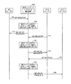
図11は、IMSベースのフォーキングを介してRCS能力情報を発見する従来のプロセスを示す。具体的には、図11は、第1のユーザがIMSサービスを求めてUE1、2、および3に登録され、UE4に登録された第2のユーザが第1のユーザに関するRCS能力情報を取得しようとしている、プロシージャを示す。
FIG. 11 shows a conventional process of discovering RCS capability information via IMS based forking. Specifically, FIG. 11 shows that the first user is registered with
図11を参照すると、UE1、2、および3がIMSネットワーク600を用いて(たとえば、図7のプロセスの早期の実行に基づいて)第1のユーザに登録され、UE1、2、および3がそれ自体のRCS能力情報を維持するが、UE1、2、および3は他の各RCS能力情報を認識しないと仮定されたい。したがって、UE1は、UE1に関するRCS能力情報を維持し(1100)、UE2は、UE2に関するRCS能力情報を維持し(1105)、UE3は、UE3に関するRCS能力情報を維持する(1110)。ある点において、第2のユーザに関連してIMSサービスを求めて登録されたUE4は、第1のユーザに関するRCS能力情報を取り出すことを決定する(1115)。UE4は、1115の決定に応答して、UE4のRCS能力を指示し第1のユーザのRCS能力情報を要求するように構成された、SIP OPTIONSメッセージをIMSネットワーク600に送信する(1120)。具体的には、1120のSIP OPTIONSメッセージは、第1のユーザ(たとえば、kate@example.com、「sip.instanceID」など)を識別するが、GRUUを介しては第1のユーザのいずれかの特定のクライアントデバイス(またはUA)を識別しない。IMSネットワーク600は、UE4からSIP OPTIONSメッセージを受信し、複数のUEが第1のユーザに登録されることを決定し、その結果、IMSネットワーク600は、そのそれぞれのGRUUを介してSIP OPTIONSメッセージを第1のユーザの登録されたUEの各々に「フォーキングする」ことを決定する(1125)。したがって、UE4からのSIP OPTIONSメッセージは、IMSネットワーク600によって、1130、1135、および1140においてそれぞれ、UE1、2、および3の各々に転送される。
Referring to FIG. 11,
図11では、UE2は、UE2に関するRCS能力情報を示すSIP 200 OKメッセージをIMSネットワーク600に送ることによってフォーキングされたSIP OPTIONSメッセージに応答する第1のUEである(1145)。IMSネットワーク600は、1145のSIP 200 OKメッセージを受信し、UE2がフォーキングされたSIP OPTIONSメッセージに対する第1の応答UEであると決定し、次いで、この決定に基づいてSIP 200 OKメッセージをUE4に転送する(1150)。後に、UE1および3はまた、そのそれぞれのRCS能力情報を示すSIP 200 OKメッセージをIMSネットワーク600に送ることによってフォーキングされたSIP OPTIONSメッセージに応答する(1155および1160)。しかしながら、IMSネットワーク600は、IMSフォーキングプロトコルに従って、第1の応答UEからのSIP 200 OKメッセージを返すだけであり、その結果、IMSネットワーク600は、UE1またはUE3からのSIP 200 OKメッセージのいずれもUE4に転送しない(1165)。したがって、図11のRCS能力発見プロシージャの後、UE4は、UE2に関するRCS能力情報を認識するが、UE1および3に関するRCS能力情報を認識せず、その理由は、UE1もUE3もフォーキングされたSIP OPTIONSメッセージに対する第1の応答機でないからである。
In FIG. 11,
図12は、サーバベースのフォーキングを介してRCS能力情報を発見する従来のプロセスを示す。具体的には、図11と同様に、図12は、第1のユーザがIMSサービスを求めてUE1、2、および3に登録され、UE4を操作する第2のユーザが第1のユーザに関するRCS能力情報を取得しようとしている、別のプロシージャを示す。
FIG. 12 shows a conventional process of discovering RCS capability information via server based forking. Specifically, as in FIG. 11, FIG. 12 shows that the first user is registered with
図12を参照すると、UE1、2、および3がIMSネットワーク600を用いて(たとえば、図7のプロセスの早期の実行に基づいて)第1のユーザに登録され、UE1、2、および3がそれ自体のRCS能力情報を維持するが、UE1、2、および3は他の各RCS能力情報を認識しないと仮定されたい。したがって、UE1は、UE1に関するRCS能力情報を維持し(1200)、UE2は、UE2に関するRCS能力情報を維持し(1205)、UE3は、UE3に関するRCS能力情報を維持する(1210)。ある点において、第2のユーザに関連してIMSサービスを求めて登録されたUE4は、第1のユーザに関するRCS能力情報を取り出すことを決定する(1215)。UE4は、1215の決定に応答して、UE4のRCS能力を指示し第1のユーザのRCS能力情報を要求するように構成された、SIP OPTIONSメッセージをIMSネットワーク600に送信する(1220)。具体的には、1220のSIP OPTIONSメッセージは、第1のユーザ(たとえば、kate@example.com、「sip.instanceID」など)を識別するが、GRUUを介しては第1のユーザのいずれの特定のクライアントデバイス(またはUA)も識別しない。IMSネットワーク600は、UE4からSIP OPTIONSメッセージを受信し、第1のユーザが登録される1つのターゲットアプリケーションサーバ(または複数のサーバ)を識別する(1225)。IMSネットワーク600は、SIP OPTIONSメッセージをターゲットアプリケーションサーバに転送する(1230)。ターゲットアプリケーションサーバは、SIP OPTIONSメッセージを受信し、複数のUEが第1のユーザに登録されることを決定し、その結果、ターゲットアプリケーションサーバは、そのそれぞれのGRUUを介してSIP OPTIONSメッセージを第1のユーザの登録されたUEの各々に「フォーキングする」ことを決定する(1235)。したがって、UE4からのSIP OPTIONSメッセージは、ターゲットアプリケーションサーバによって、1240、1245、および1250においてそれぞれ、UE1、2、および3の各々に転送される。
Referring to FIG. 12,
図12では、UE2は、UE2に関するRCS能力情報を示すSIP 200 OKメッセージをターゲットアプリケーションサーバに送ることによってフォーキングされたSIP OPTIONSメッセージに応答する第1のUEである(1255)。UE2に再びSIP 200 OKメッセージを直ちに転送するのではなく、ターゲットアプリケーションサーバは、所与の満了期間を有するタイマを開始させ、フォーキングされたSIP OPTIONSメッセージに応答する第1のユーザのUEのうちの1つまたは複数を待つ(1260)。後に、タイマの満了前に、UE1は、そのRCS能力情報を示すSIP 200 OKメッセージをターゲットアプリケーションサーバに送ることによってフォーキングされたSIP OPTIONSメッセージに応答する(1265)。ターゲットアプリケーションサーバは、フォーキングされたSIP OPTIONSメッセージに応答する第1のユーザのUEのうちの1つまたは複数を待ち続けながら、タイマを動作させ続ける(1270)。後に、タイマの満了前に、UE3は、そのRCS能力情報を示すSIP 200 OKメッセージをターゲットアプリケーションサーバに送ることによってフォーキングされたSIP OPTIONSメッセージに応答する(1275)。この点において、タイマが満了するか、第1のユーザのUEのすべてがフォーキングされたSIP OPTIONSメッセージに応答したことをターゲットアプリケーションサーバが決定し、そのことが、ターゲットアプリケーションサーバに、受信されたSIP 200 OKメッセージの各々からのRCS能力情報を単一の集合的SIP 200 OKメッセージに統合させるようにトリガすると仮定されたい(1280)。ターゲットアプリケーションサーバは、UE1、UE2、およびUE3に関するRCS能力情報を示す集合的SIP 200 OKメッセージをUE4に送信する(1285)。したがって、図12のRCS能力発見プロシージャの後、UE4は、UE1、2、および3の各々に関するRCS能力情報を認識する。しかしながら、1260および1270において起こる待機および1280において起こる後続の統合は、かなりの量の時間(たとえば、20〜30秒)がかかる場合があることが諒解されよう。この理由で、UE4が、図12のプロセスを介して図11と比較してより完全なRCS能力情報を取得する一方で、図12のRCS能力プロシージャ全体は、図11のプロセスよりも遅い。また、図12は、アプリケーションサーバの関与を必要とし、このことは、IMSネットワーク600自体がSIP OPTIONSメッセージをフォーキングする図11と比較してRCS能力プロシージャにより大きいオーバーヘッドを加える。
In FIG. 12, UE2 is the first UE to respond to a SIP OPTIONS message forked by sending a
それによって、本発明の実施形態は、異なるユーザに関するRCS能力情報を問い合わせるユーザが、図11に関して上述したRCS能力発見プロシージャの応答時間を近似するレイテンシ(または応答時間)で(たとえば、図12と同様に)他のユーザの登録されたUEの各々に関する完全な(または、ほぼ完全な)RCS能力情報を取得する、ユーザ間RCS能力発見プロシージャに向けられる。 Thereby, embodiments of the present invention have latency (or response time) that approximates the response time of the RCS capability discovery procedure described above with reference to FIG. A.) An inter-user RCS capability discovery procedure directed to obtaining complete (or nearly complete) RCS capability information for each of the other user's registered UEs.
具体的には、本発明のいくつかの実施形態は、IMSネットワーク600を用いて同じユーザに登録された1つまたは複数の他のUEのRCS能力情報を取得するために特定のユーザに登録されたUEのうちの1つ(または複数)に依拠する。図13は、同じユーザに登録されたUE間でRCS能力情報がどのように共有され得るかの一例を示す。UEのうちの1つ(または複数)が、IMSネットワーク600を用いて同じユーザに登録された他のUEに関するRCS能力情報を取得した後、これらのUEは、図14に関して以下に説明するように、フォーキングされたSIP OPTIONSメッセージに対するそのそれぞれの応答において複数のUEに関するRCS能力情報を束ねることができる。
Specifically, some embodiments of the present invention may register with a particular user to obtain RCS capability information of one or more other UEs registered with the same user using
図13を参照すると、UE1がIMSサービスを求めて第1のユーザにすでに登録され、後にUE2がGRUU[UE1]とGRUU[UE2]の両方を取得すると仮定されたい(1300)。一例では、1300は、830においてUE2に配信されるSIP 200 OKメッセージに応答して図8、図9、または図10のプロセスの実行に基づいて起こり得る。しかしながら、別の実施形態では、1300は、必ずしも登録プロシージャとともに起こる必要はない。いずれの場合でも、UE2は、GRUU[UE1]およびGRUU[UE2]を取得した後のある点において、GRUU[UE1]を対象としUE2に関するRCS能力情報を含む、SIP OPTIONSメッセージをIMSネットワーク600を介してUE1に送信する(1305)。UE1は、GRUU[UE2]を対象としUE1自体のRCS能力情報を示す、SIP 200 OKメッセージを伴うSIP OPTIONSメッセージに応答する(1310)。この点において、UE1および2は各々、それ自体のRCS能力情報、および他のUEに関するRCS能力情報を認識する(1315および1320)。
Referring to FIG. 13, assume that UE1 has already registered with the first user for IMS service and later UE2 gets both GRUU [UE1] and GRUU [UE2] (1300). In one example, 1300 can occur based on execution of the process of FIG. 8, FIG. 9, or FIG. 10 in response to the
ある後の時点において、UE3は、GRUU[UE1]、GRUU[UE2]、およびGRUU[UE3]を取得する(1325)。一例では、1325は、850においてUE3に配信されるSIP 200 OKメッセージに応答して図8、図9、または図10のプロセスの実行に基づいて起こり得る。しかしながら、別の実施形態では、1325は、必ずしも登録プロシージャとともに起こる必要はない。いずれの場合でも、UE3は、GRUU[UE1]、GRUU[UE2]、およびGRUU[UE3]を取得した後のある点において、GRUU[UE1]を対象としUE3に関するRCS能力情報を含む、SIP OPTIONSメッセージをIMSネットワーク600を介してUE1に送信する(1330)。UE1は、GRUU[UE3]を対象としUE1自体のRCS能力情報を示す、SIP 200 OKメッセージを伴うSIP OPTIONSメッセージに応答する(1335)。この点において、UE1は、UE1、2、および3の各々に関するRCS能力情報を認識し、UE3は、UE1および3に関するRCS能力情報を認識する(1340および1345)。同様に、UE3はまた、GRUU[UE1]、GRUU[UE2]、およびGRUU[UE3]を取得した後のある点において、GRUU[UE2]を対象としUE3に関するRCS能力情報を含む、SIP OPTIONSメッセージをIMSネットワーク600を介してUE2に送信する(1350)。UE2は、GRUU[UE3]を対象としUE2自体のRCS能力情報を示す、SIP 200 OKメッセージを伴うSIP OPTIONSメッセージに応答する(1355)。この点において、UE2および3はどちらも、UE1、2、および3の各々に関するRCS能力情報を認識する(1360および1365)。上述のように、図13のプロセスは、図8、図9、または図10の登録プロシージャとともに実装され得るが、図14において交換されたSIP OPTIONSメッセージが登録プロシージャ以外で発生し得ることも可能である。
At some later time, UE3 obtains GRUU [UE1], GRUU [UE2], and GRUU [UE3] (1325). In one example, 1325 may occur based on the execution of the process of FIG. 8, FIG. 9, or FIG. 10 in response to the
上記の説明から諒解されるように、図13は、IMSサービスを求めて同じユーザに登録された複数のUE間でRCS能力情報がどのように交換され得るかの一例を示す。図14は、UE1、2、および3が各々、他の各RCS能力情報を提供されるという仮定のもとで以下に説明される。この情報が、図13に関して上述のように、または何らかの他の機構を介して交換され得ることが諒解されよう。
As can be understood from the above description, FIG. 13 shows an example of how RCS capability information may be exchanged between multiple UEs registered with the same user for IMS service. FIG. 14 is described below under the assumption that
図14は、本発明の一実施形態による、IMSベースのフォーキングを介してRCS能力情報を発見するプロセスを示す。図11と同様に、図14は、第1のユーザがIMSサービスを求めてUE1、2、および3に登録され、UE4を操作する第2のユーザが第1のユーザに関するRCS能力情報を取得しようとしている、プロシージャを示す。
FIG. 14 shows a process for discovering RCS capability information via IMS based forking according to one embodiment of the present invention. Similar to FIG. 11, FIG. 14 shows that the first user is registered with
図14を参照すると、UE1、2、および3がIMSネットワーク600を用いて(たとえば、図8、図9、または図10のプロセスの早期の実行に基づいて)第1のユーザに登録され、UE1、2、および3がそれ自体のRCS能力情報と、第1のユーザに登録された他の各UEのRCS能力情報とを維持すると仮定されたい。一例では、UE1、2、および3は、上述のように、図13のプロセスの実行に基づいて第1のユーザに登録された他のUEのRCS能力情報を取得することができる。したがって、UE1は、UE1、2、および3に関するRCS能力情報を維持し(1400)、UE2は、UE1、2、および3に関するRCS能力情報を維持し(1405)、UE3も、UE1、2、および3に関するRCS能力情報を維持する(1410)。
Referring to FIG. 14,
ある点において、第2のユーザに関連してIMSサービスを求めて登録されたUE4は、第1のユーザに関するRCS能力情報を取り出すことを決定する(1415)。UE4は、1415の決定に応答して、UE4のRCS能力を指示し第1のユーザのRCS能力情報を要求するように構成された、SIP OPTIONSメッセージをIMSネットワーク600に送信する(1420)。具体的には、1420のSIP OPTIONSメッセージは、第1のユーザ(たとえば、kate@example.com、「sip.instanceID」など)を識別するが、GRUUを介しては第1のユーザのいずれの特定のクライアントデバイス(またはUA)も識別しない。IMSネットワーク600は、UE4からSIP OPTIONSメッセージを受信し、複数のUEが第1のユーザに登録されることを決定し、その結果、IMSネットワーク600は、そのそれぞれのGRUUを介してSIP OPTIONSメッセージを第1のユーザの登録されたUEの各々に「フォーキングする」ことを決定する(1425)。したがって、UE4からのSIP OPTIONSメッセージは、IMSネットワーク600によって、1430、1435、および1440においてそれぞれ、UE1、2、および3の各々に転送される。
At some point, UE 4 registered for IMS service in association with the second user decides to retrieve 1415 RCS capability information for the first user. In response to the determination of 1415, UE 4 sends a SIP OPTIONS message to
図14では、UE2は、SIP 200 OKメッセージをIMSネットワーク600に送ることによってフォーキングされたSIP OPTIONSメッセージに応答する第1のUEである(1445)。しかしながら、図11の1145のSIP 200 OKメッセージと異なり、1445のSIP 200 OKメッセージは、UE2に加えてUE1および3に関するRCS能力情報を含む。IMSネットワーク600は、1445のSIP 200 OKメッセージを受信し、UE2がフォーキングされたSIP OPTIONSメッセージに対する第1の応答UEであると決定し、次いで、この決定に基づいてSIP 200 OKメッセージをUE4に転送する(1450)。後に、UE1および3はまた、SIP 200 OKメッセージをIMSネットワーク600に送ることによってフォーキングされたSIP OPTIONSメッセージに応答する(1455および1460)。しかしながら、図11の1155および1160のSIP 200 OKメッセージと異なり、1455および1460のSIP 200 OKメッセージは各々、UE1、2、および3に関するRCS能力情報を含む。
In FIG. 14,
IMSネットワーク600は、IMSフォーキングプロトコルに従って、第1の応答UEからのSIP 200 OKメッセージを返すだけであり、その結果、IMSネットワーク600は、UE1またはUE3からのSIP 200 OKメッセージのいずれもUE4に転送しない(1465)。依然として、UE4は、第1の応答UE(すなわち、UE2)からの1445および1450のSIP 200 OKメッセージ内のRCS能力情報を束ねたために、UE1、2、および3の各々に関するRCS能力情報を取得することができる。
The
したがって、図14のRCS能力発見プロシージャの後、UE4は、UE1、2、および3の各々に関するRCS能力情報を認識する。また、RCS能力情報が第1の応答UEからIMSネットワーク600によって転送されたので、RCS能力発見に関連するレイテンシは、図14では上述の図12のプロセスと比較して低減される。
Thus, after the RCS capability discovery procedure of FIG. 14, UE 4 recognizes RCS capability information for each of
図14はIMSベースのフォーキング実装形態に関して説明したが、図14がアプリケーションサーバベースのフォーキング実装形態に対応するようにどのように修正され得るかは容易に諒解されよう。たとえば、図12のプロセスは、(たとえば、図14において仮定され、図12において示されるように)第1のユーザのUEがRCS能力情報を互いに交換するように修正される場合があり、次いで、ターゲットアプリケーションサーバが、複数のUEに関する束ねられたRCS能力情報を含む、第1の応答UEのSIP 200 OKメッセージを要求側UEに返す場合がある。
While FIG. 14 has been described with respect to an IMS based forking implementation, it will be readily appreciated how FIG. 14 can be modified to correspond to an application server based forking implementation. For example, the process of FIG. 12 may be modified such that the UEs of the first user exchange RCS capability information with each other (as assumed for example in FIG. 14 and shown in FIG. 12); The target application server may return a
情報および信号が多種多様な異なる技術および技法のいずれかを使用して表すことができることを、当業者は諒解されよう。たとえば、上記の説明全体を通して言及できるデータ、命令、コマンド、情報、信号、ビット、シンボル、およびチップは、電圧、電流、電磁波、磁場もしくは磁性粒子、光場もしくは光学粒子、またはそれらの任意の組合せによって表現することができる。 Those skilled in the art will appreciate that information and signals can be represented using any of a wide variety of different technologies and techniques. For example, data, instructions, commands, information, signals, bits, symbols and chips that may be mentioned throughout the above description may be voltage, current, electromagnetic waves, magnetic fields or particles, light fields or particles, or any combination thereof Can be expressed by
さらに、本明細書で開示された実施形態に関連して説明された様々な例示的な論理ブロック、モジュール、回路、およびアルゴリズムステップは、電子ハードウェア、コンピュータソフトウェア、または両方の組合せとして実装され得ることを、当業者は諒解されよう。ハードウェアおよびソフトウェアのこの互換性を明確に示すために、様々な例示的な構成要素、ブロック、モジュール、回路、およびステップを、上記では概してそれらの機能性に関して説明した。そのような機能がハードウェアとして実装されるか、またはソフトウェアとして実装されるかは、具体的な適用例および全体的なシステムに課される設計制約に依存する。当業者は、説明された機能を具体的な適用例ごとに様々な方法で実装することができるが、そのような実装の決定は、本発明の範囲からの逸脱を生じるものと解釈されるべきではない。 Additionally, various illustrative logic blocks, modules, circuits, and algorithmic steps described in connection with the embodiments disclosed herein may be implemented as electronic hardware, computer software, or a combination of both Those skilled in the art will appreciate that. To clearly illustrate this interchangeability of hardware and software, various illustrative components, blocks, modules, circuits, and steps have been described above generally in terms of their functionality. Whether such functionality is implemented as hardware or software depends upon the particular application and design constraints imposed on the overall system. Skilled artisans may implement the described functionality in varying ways for each particular application, but such implementation decisions should be interpreted as causing a departure from the scope of the present invention. is not.
本明細書で開示する実施形態に関して説明する様々な例示的な論理ブロック、モジュール、および回路は、汎用プロセッサ、デジタル信号プロセッサ(DSP)、特定用途向け集積回路(ASIC)、フィールドプログラマブルゲートアレイ(FPGA)または他のプログラマブル論理デバイス、個別ゲートまたはトランジスタ論理、個別ハードウェア構成要素、または本明細書で説明する機能を実行するように設計されたそれらの任意の組合せで実装または実行することができる。汎用プロセッサはマイクロプロセッサであり得るが、代替として、プロセッサは任意の従来のプロセッサ、コントローラ、マイクロコントローラ、または状態機械であり得る。プロセッサはまた、コンピューティングデバイスの組合せ、たとえば、DSPおよびマイクロプロセッサの組合せ、複数のマイクロプロセッサ、DSPコアと連携する1つもしくは複数のマイクロプロセッサ、または任意の他のそのような構成として実装され得る。 The various exemplary logic blocks, modules, and circuits described with respect to the embodiments disclosed herein may be general purpose processors, digital signal processors (DSPs), application specific integrated circuits (ASICs), field programmable gate arrays (FPGAs) Or other programmable logic devices, discrete gates or transistor logic, discrete hardware components, or any combination thereof designed to perform the functions described herein. A general purpose processor may be a microprocessor, but in the alternative, the processor may be any conventional processor, controller, microcontroller, or state machine. The processor may also be implemented as a combination of computing devices, eg, a combination of DSP and microprocessor, multiple microprocessors, one or more microprocessors in conjunction with a DSP core, or any other such configuration .
本明細書で開示した実施形態に関連して説明した方法、シーケンス、および/またはアルゴリズムは、ハードウェアで、プロセッサによって実行されるソフトウェアモジュールで、またはその2つの組合せで直接具体化され得る。ソフトウェアモジュールは、RAMメモリ、フラッシュメモリ、ROMメモリ、EPROMメモリ、EEPROMメモリ、レジスタ、ハードディスク、リムーバブルディスク、CD-ROM、または当技術分野で知られている任意の他の形態の記憶媒体中に常駐し得る。例示的な記憶媒体は、プロセッサが記憶媒体から情報を読み取り、かつ記憶媒体に情報を書き込むことができるように、プロセッサに結合される。代替形態において、記憶媒体はプロセッサと一体であり得る。プロセッサおよび記憶媒体はASIC内に存在することができる。ASICはユーザ端末(たとえば、UE)中に存在し得る。代替として、プロセッサおよび記憶媒体は、ユーザ端末内に個別構成要素として存在することができる。 The methods, sequences, and / or algorithms described in connection with the embodiments disclosed herein may be embodied directly in hardware, in a software module executed by a processor, or in a combination of the two. The software module resides in RAM memory, flash memory, ROM memory, EPROM memory, EEPROM memory, registers, hard disk, removable disk, CD-ROM, or any other form of storage medium known in the art It can. An exemplary storage medium is coupled to the processor such that the processor can read information from, and write information to, the storage medium. In the alternative, the storage medium may be integral to the processor. The processor and the storage medium may reside in an ASIC. The ASIC may reside in a user terminal (eg, a UE). In the alternative, the processor and the storage medium may reside as discrete components in a user terminal.
1つまたは複数の例示的な実施形態では、説明される機能は、ハードウェア、ソフトウェア、ファームウェア、またはそれらの任意の組合せにおいて実装され得る。ソフトウェアに実装された場合、機能は、1つまたは複数の命令またはコードとして、コンピュータ可読記録媒体上に記憶されるか、またはコンピュータ可読記録媒体を介して送信され得る。コンピュータ可読記録媒体は、ある場所から別の場所へのコンピュータプログラムの転送を容易にする任意の媒体を含む、コンピュータ記憶媒体と通信媒体の両方を含む。記憶媒体は、コンピュータによってアクセス可能である任意の入手可能な媒体とすることができる。例として、限定はしないが、そのようなコンピュータ可読記録媒体は、RAM、ROM、EEPROM、CD-ROMもしくは他の光ディスク記憶装置、磁気ディスク記憶装置もしくは他の磁気記憶デバイス、または、命令またはデータ構造の形態の所望のプログラムコードを搬送または記憶するために用いることができ、コンピュータによってアクセス可能である、任意の他の媒体を含むことができる。また、当然、あらゆる接続がコンピュータ可読記録媒体と呼ばれる。たとえば、ソフトウェアが、同軸ケーブル、光ファイバケーブル、ツイストペア、デジタル加入者回線(DSL)、または赤外線、無線、およびマイクロ波などのワイヤレス技術を使用して、ウェブサイト、サーバ、または他のリモートソースから送信される場合、同軸ケーブル、光ファイバケーブル、ツイストペア、DSL、または赤外線、無線、およびマイクロ波などのワイヤレス技術は、媒体の定義に含まれる。本明細書で使用する場合、ディスク(disk)およびディスク(disc)は、コンパクトディスク(CD)、レーザーディスク(登録商標)、光ディスク、デジタル多用途ディスク(DVD)、フロッピー(登録商標)ディスク、およびブルーレイディスクを含み、ディスク(disk)は、通常、磁気的にデータを再生するが、ディスク(disc)は、レーザーで光学的にデータを再生する。上記の組合せもコンピュータ可読記録媒体の範囲内に含めるべきである。 In one or more exemplary embodiments, the functions described may be implemented in hardware, software, firmware, or any combination thereof. When implemented in software, the functions may be stored on or transmitted over as one or more instructions or code on a computer readable recording medium. Computer-readable media includes both computer storage media and communication media including any medium that facilitates transfer of a computer program from one place to another. A storage media may be any available media that can be accessed by a computer. By way of example and not limitation, such computer readable recording media may be RAM, ROM, EEPROM, CD-ROM or other optical disk storage, magnetic disk storage or other magnetic storage device, or instructions or data structures And any other medium that can be used to carry or store desired program code in the form of and accessible by a computer. Also, of course, any connection is called a computer readable recording medium. For example, software may use coaxial cable, fiber optic cable, twisted pair, digital subscriber line (DSL), or wireless technology such as infrared, wireless, and microwave from a website, server, or other remote source When transmitted, coaxial technologies, fiber optic cables, twisted pair, DSL, or wireless technologies such as infrared, wireless, and microwave are included in the definition of medium. As used herein, disks and discs are compact disks (CDs), laser disks (registered trademark), optical disks, digital versatile disks (DVDs), floppy disks, and A Blu-ray disc is included, and a disc normally reproduces data magnetically, whereas a disc reproduces data optically with a laser. Combinations of the above should also be included within the scope of computer readable recording media.
上記の開示は本発明の例示的な実施形態を示すが、添付の特許請求の範囲によって定義された本発明の範囲から逸脱することなく、様々な変更および修正を本明細書において加えることができることを留意されたい。本明細書で説明する本発明の実施形態による機能、ステップ、および/または方法クレームのアクションが任意の特定の順序で実行される必要はない。さらに、本発明の要素は、単数で記載され、または請求されているが、単数への制限が明示的に述べられない限り、複数は企図される。 While the above disclosure describes exemplary embodiments of the present invention, various changes and modifications may be made herein without departing from the scope of the present invention as defined by the appended claims. Please be aware. The actions of features, steps and / or method claims in accordance with the embodiments of the invention described herein need not be performed in any particular order. Furthermore, although elements of the invention may be described or claimed in the singular, the plural is contemplated unless limitation to the singular is explicitly stated.
100 ワイヤレス通信システム
104 エアインターフェース
106 エアインターフェース
108 エアインターフェース
120 無線アクセスネットワーク(RAN)
120A 3GPP RAN
120B 非3GPP RAN
125 アクセスポイント(AP)
140 コアネットワーク
170 アプリケーションサーバ
175 インターネット
200A 基地局
205A 基地局
210A 基地局
215A 基地局コントローラ(BSC)
220A パケット制御機能(PCF)
225A パケットデータサービングノード
200B ノードB
205B ノードB
210B ノードB
215B 無線ネットワークコントローラ(RNC)
220B サービングGRPSサポートノード(SGSN)
225B ゲートウェイ汎用パケット無線サービス(GPRS)サポートノード(GGSN)
200D eノードB
205D eノードB
210D eノードB
215D モビリティ管理エンティティ(MME)
220D モビリティ管理エンティティ(MME)
225D ホーム加入者サーバ(HSS)
230D サービングゲートウェイ(S-GW)
235D パケットデータネットワークゲートウェイ(P-GW)
240D ポリシーおよび課金ルール機能(PCRF)
200E トランシーバ基地局(BTS)
205E トランシーバ基地局(BTS)
210E トランシーバ基地局(BTS)
215E 拡張型BSC(eBSC)および拡張型PCF(ePCF)
220E HRPDサービングゲートウェイ(HSGW)
225E 認証、許可、およびアカウンティング(AAA)サーバ
230E PDSN/FA
235E HA
300A UE(発呼側)
300B UE(タッチスクリーンデバイス)
302 プラットフォーム
305A アンテナ
305B タッチスクリーンディスプレイ
306 トランシーバ
308 特定用途向け集積回路(ASIC)
310 アプリケーションプログラミングインターフェース(API)
310A ディスプレイ
310B 周辺ボタン
312 メモリ
314 ローカルデータベース
315A ボタン
315B 周辺ボタン
320A キーパッド
320B 周辺ボタン
325B 周辺ボタン
330B フロントパネルボタン
400 通信デバイス
405 情報を受信および/または送信するように構成された論理
410 情報を処理するように構成された論理
415 情報を記憶するように構成された論理
420 情報を提示するように構成された論理
425 ローカルユーザ入力を受信するように構成された論理
500 サーバ
501 プロセッサ
502 揮発性メモリ
503 ディスク(disk)ドライブ
504 ネットワークアクセスポート
506 ディスク(disc)ドライブ
507 ネットワーク
600 IMSネットワーク
605 プロキシ呼セッション制御機能(P-CSCF)
610 問合せCSCF(I-CSCF)
615 サービングCSCF(S-CSCF)
620 ホーム加入者サーバ(HSS)
AS アプリケーションサーバ
100 wireless communication system
104 air interface
106 air interface
108 air interface
120 Radio Access Network (RAN)
120A 3GPP RAN
120 B non-3 GPP RAN
125 Access Points (AP)
140 core network
170 Application Server
175 Internet
200A base station
205A base station
210A base station
215A Base Station Controller (BSC)
220A packet control function (PCF)
225A Packet Data Serving Node
200 B Node B
205B Node B
210B Node B
215B Radio Network Controller (RNC)
220B Serving GRPS Support Node (SGSN)
225B Gateway General Packet Radio Service (GPRS) Support Node (GGSN)
200D eNodeB
205D eNodeB
210D eNodeB
215D Mobility Management Entity (MME)
220D Mobility Management Entity (MME)
225D Home Subscriber Server (HSS)
230D Serving Gateway (S-GW)
235D Packet Data Network Gateway (P-GW)
240D Policy and Charging Rules Function (PCRF)
200E transceiver base station (BTS)
205E transceiver base station (BTS)
210E Transceiver Base Station (BTS)
215E Enhanced BSC (eBSC) and Enhanced PCF (ePCF)
220E HRPD Serving Gateway (HSGW)
225E Authentication, Authorization, and Accounting (AAA) Server
230E PDSN / FA
235E HA
300A UE (Calling party)
300B UE (touch screen device)
302 platform
305A antenna
305B touch screen display
306 transceiver
308 Application Specific Integrated Circuits (ASIC)
310 Application Programming Interface (API)
310A display
310B Peripheral button
312 memory
314 Local Database
315A button
315B Peripheral button
320A Keypad
320B Peripheral button
325B Peripheral button
330B front panel button
400 communication device
405 Logic configured to receive and / or transmit information
410 Logic configured to process information
415 Logic configured to store information
420 logic configured to present information
425 Logic configured to receive local user input
500 server
501 processor
502 volatile memory
503 disk drive
504 Network Access Port
506 disc drive
507 Network
600 IMS network
605 Proxy call session control function (P-CSCF)
610 Inquiry CSCF (I-CSCF)
615 Serving CSCF (S-CSCF)
620 Home Subscriber Server (HSS)
AS application server
Claims (15)
前記クライアントデバイスによって、インターネットプロトコル(IP)マルチメディアサブシステム(IMS)サービスを求めて第1のユーザに前記クライアントデバイスを登録するためにIMSネットワークを用いて登録プロシージャを実行するステップ(800、810、815、830、835、850、1300、1325)と、
前記クライアントデバイスによって、1つまたは複数の他のクライアントデバイスに関するリッチコミュニケーションスイート(RCS)能力情報を取得するために前記IMSサービスを求めて前記第1のユーザに同様に登録された前記1つまたは複数の他のクライアントデバイスと通信するステップ(1305、1310、1330、1335、1350、1355)と、
前記クライアントデバイスによって、前記クライアントデバイスのRCS能力情報を報告することを求める要求を受信するステップ(1430、1435、1440)と、
前記クライアントデバイスによって、前記受信された要求に応答して、(i)前記クライアントデバイスのRCS能力情報と(ii)前記1つまたは複数の他のクライアントデバイスに関する前記RCS能力情報の両方を示すメッセージを送信するステップ(1445、1455、1460)と
を含む、方法。 A method of operating a client device (300A, 300B, 400) associated with a first user, comprising:
Performing a registration procedure using the IMS network to register the client device with a first user for an Internet Protocol (IP) Multimedia Subsystem (IMS) service by the client device (800, 810, 815, 830, 835, 850, 1300, 1325),
The one or more similarly registered with the first user for the IMS service to obtain rich communication suite (RCS) capability information regarding one or more other client devices by the client device Communicating with the other client devices of (1305, 1310, 1330, 1335, 1350, 1355);
Receiving, by the client device, a request for reporting RCS capability information of the client device (1430, 1435, 1440);
The client device responds with the received request to: (i) a message indicating both the RCS capability information of the client device and (ii) the RCS capability information for the one or more other client devices And transmitting (1445, 1455, 1460).
前記クライアントデバイスを前記IMSサービスに登録することを求める要求を前記IMSネットワークに送信するステップと、
前記送信された要求に応答して、前記クライアントデバイスがデバイス固有のルーティング識別子の第1の組を用いて前記IMSサービスに登録されるという通知を受信するステップと
を含み、
前記通知が、前記IMSサービスを求めて前記1つまたは複数の他のクライアントデバイスに以前に割り当てられたデバイス固有のルーティング識別子の少なくとも1つの追加の組の指示をさらに含み、
前記通信するステップが、前記1つまたは複数の他のクライアントデバイスに関する前記RCS能力情報を取得するためにデバイス固有のルーティング識別子の前記少なくとも1つの追加の組を使用する、
請求項1に記載の方法。 The registration procedure
Sending a request to the IMS network to register the client device with the IMS service;
Receiving, in response to the sent request, a notification that the client device is registered with the IMS service using a first set of device-specific routing identifiers.
The notification further includes an indication of at least one additional set of device-specific routing identifiers previously assigned to the one or more other client devices for the IMS service,
The communicating step uses the at least one additional set of device specific routing identifiers to obtain the RCS capability information for the one or more other client devices.
The method of claim 1.
デバイス固有のルーティング識別子の前記少なくとも1つの追加の組に基づく宛先アドレスを用いて1つまたは複数のセッション開始プロトコル(SIP)OPTIONSメッセージを構成
するステップと、
前記1つまたは複数のSIP OPTIONSメッセージを前記1つまたは複数の他のクライアントデバイスに送信するステップであって、前記送信された1つまたは複数のSIP OPTIONSメッセージの各々が前記クライアントデバイスに関する前記RCS能力情報を示す、ステップと、
前記送信するステップに応答して前記1つまたは複数の他のクライアントデバイスから、SIP 200 OKメッセージが発生した前記他のクライアントデバイスに関する前記RCS能力情報を各々が示す1つまたは複数のSIP 200 OKメッセージを受信するステップと
を含む、請求項2に記載の方法。 The communicating step comprises
Configuring one or more Session Initiation Protocol (SIP) OPTIONS messages with a destination address based on the at least one additional set of device specific routing identifiers;
Sending the one or more SIP OPTIONS messages to the one or more other client devices, wherein each of the sent one or more SIP OPTIONS messages is the RCS capability for the client device Show information, and
One or more SIP 200 OK messages, each indicating the RCS capability information for the other client device from which the SIP 200 OK message occurred, from the one or more other client devices in response to the sending step And receiving the information.
前記送信されたメッセージが、第2のSIP 200 OKメッセージである、
請求項1に記載の方法。 The received request is a Session Initiation Protocol (SIP) OPTIONS message,
The sent message is a second SIP 200 OK message,
The method of claim 1.
前記送信するステップが、前記メッセージを前記IMSネットワークに送信する、
請求項8に記載の方法。 The forked request is forked in the IMS network,
The sending step sends the message to the IMS network.
The method of claim 8.
前記送信するステップが、前記メッセージを前記アプリケーションサーバに送信する、
請求項8に記載の方法。 The forked request is forked at an application server external to the IMS network and assigned to the client device and the one or more other client devices to support the IMS service.
The sending step sends the message to the application server.
The method of claim 8.
インターネットプロトコル(IP)マルチメディアサブシステム(IMS)サービスを求めて第1のユーザに前記クライアントデバイスを登録するためにIMSネットワークを用いて登録プロシージャを実行する(800、810、815、830、835、850、1300、1325)ための手段(405、410)と、
1つまたは複数の他のクライアントデバイスに関するRCS能力情報を取得するために前記IMSサービスを求めて前記第1のユーザに同様に登録された前記1つまたは複数の他のクライアントデバイスと通信する(1305、1310、1330、1335、1350、1355)ための手段(405)と、
前記クライアントデバイスのリッチコミュニケーションスイート(RCS)能力情報を報告することを求める要求を受信する(1430、1435、1440)ための手段(405)と、
前記受信された要求に応答して、(i)前記クライアントデバイスのRCS能力情報と(ii)前記1つまたは複数の他のクライアントデバイスに関する前記RCS能力情報の両方を示すメッセージを送信する(1445、1455、1460)ための手段(405)と
を含む、クライアントデバイス。 A client device (300A, 300B, 400) associated with the first user,
Execute a registration procedure using an IMS network to register the client device with a first user for an Internet Protocol (IP) Multimedia Subsystem (IMS) service (800, 810, 815, 830, 835, 850, 1300, 1325) means (405, 410);
Communicate with the one or more other client devices that are similarly registered with the first user for the IMS service to obtain RCS capability information for one or more other client devices (1305 , Means (405) for 1310, 1330, 1335, 1350, 1355),
Means (405) for receiving (1430, 1435, 1440) a request for reporting rich communication suite ( RCS ) capability information of the client device;
In response to the received request, send a message indicating (i) both the RCS capability information of the client device and (ii) the RCS capability information for the one or more other client devices (1445) And a means (405) for the client device.
前記クライアントデバイスを前記IMSサービスに登録することを求める要求を前記IMSネットワークに送信するための手段と、
前記送信された要求に応答して、前記クライアントデバイスがデバイス固有のルーティング識別子の第1の組を用いて前記IMSサービスに登録されるという通知を受信するための手段と
を含み、
前記通知が、前記IMSサービスを求めて前記1つまたは複数の他のクライアントデバイスに以前に割り当てられたデバイス固有のルーティング識別子の少なくとも1つの追加の組の指示をさらに含み、
通信するための前記手段が、前記1つまたは複数の他のクライアントデバイスに関する前記RCS能力情報を取得するためにデバイス固有のルーティング識別子の前記少なくとも1つの追加の組を使用する、
請求項11に記載のクライアントデバイス。 Said means for performing
Means for sending a request to the IMS network to register the client device with the IMS service;
Means for receiving, in response to the sent request, a notification that the client device is registered with the IMS service using a first set of device-specific routing identifiers.
The notification further includes an indication of at least one additional set of device-specific routing identifiers previously assigned to the one or more other client devices for the IMS service,
The means for communicating uses the at least one additional set of device specific routing identifiers to obtain the RCS capability information for the one or more other client devices.
A client device according to claim 11.
インターネットプロトコル(IP)マルチメディアサブシステム(IMS)サービスを求めて第1のユーザに前記クライアントデバイスを登録するためにIMSネットワークを用いて登録プロシージャを前記クライアントデバイスに実行させる(800、810、815、830、835、850、1300、1325)ように構成された少なくとも1つの命令と、
1つまたは複数の他のクライアントデバイスに関するRCS能力情報を取得するために前記IMSサービスを求めて前記第1のユーザに同様に登録された前記1つまたは複数の他のクライアントデバイスと前記クライアントデバイスに通信させる(1305、1310、1330、1335、1350、1355)ように構成された少なくとも1つの命令と、
前記クライアントデバイスのリッチコミュニケーションスイート(RCS)能力情報を報告することを求める要求を前記クライアントデバイスに受信させる(1430、1435、1440)ように構成された少なくとも1つの命令と、
前記受信された要求に応答して、(i)前記クライアントデバイスのRCS能力情報と(ii)前記1つまたは複数の他のクライアントデバイスに関する前記RCS能力情報の両方を示すメッセージを前記クライアントデバイスに送信させる(1445、1455、1460)ように構成された少なくとも1つの命令と
を含む、非一時的コンピュータ可読記憶媒体。 A non-transitory computer readable storage medium (415) comprising stored instructions that, when executed by a client device (300A, 300B, 400) associated with a first user, causes the client device to perform an operation. The instruction is
Have the first user perform the registration procedure using the IMS network to register the client device for Internet Protocol (IP) Multimedia Subsystem (IMS) services (800, 810, 815, 830, 835, 850, 1300, 1325) at least one instruction configured as
To the one or more other client devices and the client device also registered with the first user for the IMS service to obtain RCS capability information regarding one or more other client devices At least one instruction configured to communicate (1305, 1310, 1330, 1335, 1350, 1355);
At least one instruction configured to cause the client device to receive a request to report rich communication suite ( RCS ) capability information of the client device (1430, 1435, 1440);
In response to the received request, send a message to the client device indicating (i) the RCS capability information of the client device and (ii) the RCS capability information for the one or more other client devices Non-transitory computer readable storage medium comprising at least one instruction configured to: (1445, 1455, 1460).
前記クライアントデバイスを前記IMSサービスに登録することを求める要求を前記IMSネットワークへ前記クライアントデバイスに送信させるように構成された少なくとも1つの命令と、
前記送信された要求に応答して、前記クライアントデバイスがデバイス固有のルーティング識別子の第1の組を用いて前記IMSサービスに登録されるという通知を前記クライアントデバイスに受信させるように構成された少なくとも1つの命令と
を含み、
前記通知が、前記IMSサービスを求めて前記1つまたは複数の他のクライアントデバイスに以前に割り当てられたデバイス固有のルーティング識別子の少なくとも1つの追加の組の指示をさらに含み、
前記クライアントデバイスに通信させるように構成された前記少なくとも1つの命令が、前記1つまたは複数の他のクライアントデバイスに関する前記RCS能力情報を取得するためにデバイス固有のルーティング識別子の前記少なくとも1つの追加の組を使用する、
請求項14に記載の非一時的コンピュータ可読記憶媒体。 The at least one instruction configured to cause the client device to execute
At least one instruction configured to cause the client device to send a request to the IMS network to register the client device with the IMS service;
At least one configured to cause the client device to receive a notification that the client device is registered with the IMS service using a first set of device-specific routing identifiers in response to the transmitted request; Containing one instruction and
The notification further includes an indication of at least one additional set of device-specific routing identifiers previously assigned to the one or more other client devices for the IMS service,
The at least one instruction configured to cause the client device to communicate further includes at least one additional device-specific routing identifier to obtain the RCS capability information for the one or more other client devices. Use a pair,
The non-transitory computer readable storage medium according to claim 14 .
Applications Claiming Priority (3)
| Application Number | Priority Date | Filing Date | Title |
|---|---|---|---|
| US13/972,791 | 2013-08-21 | ||
| US13/972,791 US9277522B2 (en) | 2013-08-21 | 2013-08-21 | Exchanging rich communication suite capability information in a communications system |
| PCT/US2014/051224 WO2015026647A1 (en) | 2013-08-21 | 2014-08-15 | Exchanging rich communication suite capability information in a communications system |
Publications (3)
| Publication Number | Publication Date |
|---|---|
| JP2016533117A JP2016533117A (en) | 2016-10-20 |
| JP2016533117A5 JP2016533117A5 (en) | 2017-08-31 |
| JP6505706B2 true JP6505706B2 (en) | 2019-04-24 |
Family
ID=51535506
Family Applications (1)
| Application Number | Title | Priority Date | Filing Date |
|---|---|---|---|
| JP2016536334A Active JP6505706B2 (en) | 2013-08-21 | 2014-08-15 | Exchange of rich communication suite capability information in communication system |
Country Status (5)
| Country | Link |
|---|---|
| US (1) | US9277522B2 (en) |
| EP (1) | EP3036879B1 (en) |
| JP (1) | JP6505706B2 (en) |
| CN (1) | CN105493468B (en) |
| WO (1) | WO2015026647A1 (en) |
Families Citing this family (26)
| Publication number | Priority date | Publication date | Assignee | Title |
|---|---|---|---|---|
| CN103685200B (en) * | 2012-09-24 | 2018-01-30 | 中兴通讯股份有限公司 | The method and system of service quality bearer resources control in access negotiation, release |
| WO2015076714A1 (en) * | 2013-11-22 | 2015-05-28 | Telefonaktiebolaget L M Ericsson (Publ) | Centralised capability discovery |
| FR3014632A1 (en) * | 2013-12-06 | 2015-06-12 | Orange | METHOD AND DEVICE FOR ESTABLISHING COMMUNICATION |
| US20160164945A1 (en) * | 2014-12-04 | 2016-06-09 | Futurewei Technologies, Inc. | Method Of Service Capability Discovery Based On Subscriptions For Service Notifications |
| CN106464761A (en) * | 2014-12-25 | 2017-02-22 | 株式会社Ntt都科摩 | Internetwork connection control device, and connection control method |
| CN106161177B (en) * | 2015-03-24 | 2020-02-18 | 中兴通讯股份有限公司 | Method and system for realizing intercommunication between voice mail system and converged communication system |
| CN107534838B (en) * | 2015-05-07 | 2019-11-29 | 华为技术有限公司 | A kind of method for processing business and user equipment |
| US11172410B2 (en) | 2015-09-30 | 2021-11-09 | Apple Inc. | Device, system and method for synchronizing multiple devices |
| CN106604260B (en) * | 2015-10-20 | 2021-12-21 | 中兴通讯股份有限公司 | Application downloading method and device |
| US10003656B2 (en) * | 2015-11-23 | 2018-06-19 | Samsung Electronics Co., Ltd. | System and method for sharing data/objects between electronic devices via IMS infrastructure |
| FR3045999A1 (en) * | 2015-12-18 | 2017-06-23 | Orange | METHOD FOR COMMUNICATING BETWEEN A CALLER AND A PLURALITY OF TERMINALS CALLED |
| CN107343285B (en) * | 2016-04-28 | 2022-05-13 | 中兴通讯股份有限公司 | Management equipment and equipment management method |
| CN106412855B (en) * | 2016-06-30 | 2020-11-27 | 北京小米移动软件有限公司 | Information reminding and transmitting method and device |
| US10153993B2 (en) * | 2016-07-18 | 2018-12-11 | T-Mobile Usa, Inc. | RCS origination forking |
| US10237212B2 (en) * | 2016-07-18 | 2019-03-19 | T-Mobile Usa, Inc. | RCS origination forking |
| US10111068B2 (en) * | 2016-07-29 | 2018-10-23 | Qualcomm Incorporated | Techniques for providing IMS services to multiple machine-type communication devices using a user equipment as a proxy |
| CN108696484B (en) * | 2017-04-07 | 2022-03-18 | 中兴通讯股份有限公司 | Registration method, device and storage medium |
| KR102266879B1 (en) * | 2017-04-14 | 2021-06-22 | 삼성전자주식회사 | A system for providing dialog contents |
| CN107509176A (en) * | 2017-09-13 | 2017-12-22 | 广东欧珀移动通信有限公司 | Method for building up and device, the computer-readable storage medium of a kind of group |
| CN108521427A (en) * | 2018-04-19 | 2018-09-11 | 济南浪潮高新科技投资发展有限公司 | I-CSCF servers based on Heterogeneous Computing and method |
| CN111130616B (en) * | 2018-11-01 | 2022-09-09 | 中兴通讯股份有限公司 | Session control method and satellite ground station |
| CN112448880A (en) * | 2019-09-02 | 2021-03-05 | 中兴通讯股份有限公司 | Method and device for sending RCS service message, client and server |
| US20210250384A1 (en) * | 2020-02-12 | 2021-08-12 | Apple Inc. | IMS Support for Non-Voice Services |
| US11588862B2 (en) * | 2020-10-28 | 2023-02-21 | At&T Intellectual Property I, L.P. | Method for providing voice service to roaming wireless users |
| US11374983B1 (en) | 2021-01-29 | 2022-06-28 | Sprint Communications Company L.P. | Media content service delivery in a wireless communication network |
| US20230117615A1 (en) * | 2021-10-19 | 2023-04-20 | At&T Intellectual Property I, L.P. | Api driven subscriber ims registration status changes and ims routing steering |
Family Cites Families (14)
| Publication number | Priority date | Publication date | Assignee | Title |
|---|---|---|---|---|
| GB0213728D0 (en) * | 2002-06-14 | 2002-07-24 | Nokia Corp | A communication system |
| CN100484141C (en) | 2005-03-28 | 2009-04-29 | 华为技术有限公司 | Method for realizing terminal ability interaction and route control in IMS and CS service concurrence |
| US8391165B2 (en) | 2005-12-30 | 2013-03-05 | Motorola Mobility Llc | Method and apparatus for identifying caller preferences matched to callee capabilities for IMS communications |
| JP2008219490A (en) * | 2007-03-05 | 2008-09-18 | Nec Corp | Network system and address conversion method |
| EP2263361B1 (en) * | 2008-04-02 | 2012-11-21 | Telefonaktiebolaget L M Ericsson (PUBL) | Service delivery to a consumer electronic device using a mobile communication unit for access and service control |
| US8924552B2 (en) * | 2008-05-12 | 2014-12-30 | Telefonaktiebolaget L M Ericsson (Publ) | Remote and local compound device capabilities synchronization method and system |
| US9602552B2 (en) * | 2008-06-02 | 2017-03-21 | Blackberry Limited | Coding and behavior when receiving an IMS emergency session indicator from authorized source |
| EP2166733B1 (en) | 2008-09-23 | 2011-12-21 | Research In Motion Limited | Methods and systems for aggregating presence information to provide a simplified unified presence |
| DK2205020T3 (en) * | 2008-12-31 | 2018-01-02 | Telia Co Ab | Capacity service in a communication system |
| US20110019650A1 (en) * | 2009-07-21 | 2011-01-27 | Sabine Van Niekerk | Methods and apparatus for optimization of device capability exchange in a network |
| CN101909019A (en) | 2010-07-27 | 2010-12-08 | 中兴通讯股份有限公司 | Method and system for processing request message |
| ES2813430T3 (en) * | 2011-02-11 | 2021-03-23 | Vodafone Ip Licensing Ltd | Communications method based on service capacity and social presence |
| CN102958107B (en) | 2011-08-22 | 2016-11-23 | 华为技术有限公司 | A kind of method of capability query, communication terminal and application server |
| US9106671B2 (en) | 2011-08-23 | 2015-08-11 | Telefonaktiebolaget L M Ericsson (Publ) | Capability discovery optimization |
-
2013
- 2013-08-21 US US13/972,791 patent/US9277522B2/en not_active Expired - Fee Related
-
2014
- 2014-08-15 CN CN201480046260.0A patent/CN105493468B/en not_active Expired - Fee Related
- 2014-08-15 WO PCT/US2014/051224 patent/WO2015026647A1/en active Application Filing
- 2014-08-15 EP EP14762125.4A patent/EP3036879B1/en not_active Not-in-force
- 2014-08-15 JP JP2016536334A patent/JP6505706B2/en active Active
Also Published As
| Publication number | Publication date |
|---|---|
| CN105493468B (en) | 2018-10-16 |
| EP3036879B1 (en) | 2017-09-20 |
| CN105493468A (en) | 2016-04-13 |
| US20150055550A1 (en) | 2015-02-26 |
| JP2016533117A (en) | 2016-10-20 |
| EP3036879A1 (en) | 2016-06-29 |
| US9277522B2 (en) | 2016-03-01 |
| WO2015026647A1 (en) | 2015-02-26 |
Similar Documents
| Publication | Publication Date | Title |
|---|---|---|
| JP6505706B2 (en) | Exchange of rich communication suite capability information in communication system | |
| JP6099825B2 (en) | Updating contact information about client devices registered with the same user for Internet Protocol multimedia subsystem services | |
| JP6505679B2 (en) | Updating rich communication suite capability information via a communication network | |
| JP6416361B2 (en) | Server-mediated peer-to-peer communication offloading from network infrastructure | |
| JP6370810B2 (en) | Quality of service for web client-based sessions | |
| JP6396997B2 (en) | Selecting an application server to register one or more user equipment for an Internet Protocol Multimedia Subsystem (IMS) session | |
| EP3036887B1 (en) | Single network registration where multiple applications access the network using separate processors | |
| WO2016069312A1 (en) | Exchanging floor arbitration history information during a communication session | |
| JP6622813B2 (en) | Sharing proximity discovery announcements in wireless communication networks | |
| EP3210401A1 (en) | Selectively triggering a communicative action based on whether a quorum condition for a peer-to-peer group is satisfied | |
| JP2017502604A (en) | Apparatus and method for avoiding data loss after inter-PDSN handoff based on simple IP network | |
| KR20150079828A (en) | Offloading call processing and call hosting for a small group call to a client device |
Legal Events
| Date | Code | Title | Description |
|---|---|---|---|
| A521 | Request for written amendment filed |
Free format text: JAPANESE INTERMEDIATE CODE: A523 Effective date: 20170724 |
|
| A621 | Written request for application examination |
Free format text: JAPANESE INTERMEDIATE CODE: A621 Effective date: 20170724 |
|
| A977 | Report on retrieval |
Free format text: JAPANESE INTERMEDIATE CODE: A971007 Effective date: 20180706 |
|
| A131 | Notification of reasons for refusal |
Free format text: JAPANESE INTERMEDIATE CODE: A131 Effective date: 20180806 |
|
| TRDD | Decision of grant or rejection written | ||
| A01 | Written decision to grant a patent or to grant a registration (utility model) |
Free format text: JAPANESE INTERMEDIATE CODE: A01 Effective date: 20190304 |
|
| A61 | First payment of annual fees (during grant procedure) |
Free format text: JAPANESE INTERMEDIATE CODE: A61 Effective date: 20190327 |
|
| R150 | Certificate of patent or registration of utility model |
Ref document number: 6505706 Country of ref document: JP Free format text: JAPANESE INTERMEDIATE CODE: R150 |
|
| R250 | Receipt of annual fees |
Free format text: JAPANESE INTERMEDIATE CODE: R250 |
|
| R250 | Receipt of annual fees |
Free format text: JAPANESE INTERMEDIATE CODE: R250 |