JP6504938B2 - Substrate for liquid discharge head and liquid discharge head - Google Patents
Substrate for liquid discharge head and liquid discharge head Download PDFInfo
- Publication number
- JP6504938B2 JP6504938B2 JP2015128154A JP2015128154A JP6504938B2 JP 6504938 B2 JP6504938 B2 JP 6504938B2 JP 2015128154 A JP2015128154 A JP 2015128154A JP 2015128154 A JP2015128154 A JP 2015128154A JP 6504938 B2 JP6504938 B2 JP 6504938B2
- Authority
- JP
- Japan
- Prior art keywords
- electrode
- discharge head
- liquid discharge
- substrate
- liquid
- Prior art date
- Legal status (The legal status is an assumption and is not a legal conclusion. Google has not performed a legal analysis and makes no representation as to the accuracy of the status listed.)
- Active
Links
Images


Classifications
-
- B—PERFORMING OPERATIONS; TRANSPORTING
- B41—PRINTING; LINING MACHINES; TYPEWRITERS; STAMPS
- B41J—TYPEWRITERS; SELECTIVE PRINTING MECHANISMS, i.e. MECHANISMS PRINTING OTHERWISE THAN FROM A FORME; CORRECTION OF TYPOGRAPHICAL ERRORS
- B41J2/00—Typewriters or selective printing mechanisms characterised by the printing or marking process for which they are designed
- B41J2/005—Typewriters or selective printing mechanisms characterised by the printing or marking process for which they are designed characterised by bringing liquid or particles selectively into contact with a printing material
- B41J2/01—Ink jet
- B41J2/135—Nozzles
- B41J2/14—Structure thereof only for on-demand ink jet heads
- B41J2/14016—Structure of bubble jet print heads
- B41J2/14072—Electrical connections, e.g. details on electrodes, connecting the chip to the outside...
-
- B—PERFORMING OPERATIONS; TRANSPORTING
- B41—PRINTING; LINING MACHINES; TYPEWRITERS; STAMPS
- B41J—TYPEWRITERS; SELECTIVE PRINTING MECHANISMS, i.e. MECHANISMS PRINTING OTHERWISE THAN FROM A FORME; CORRECTION OF TYPOGRAPHICAL ERRORS
- B41J2/00—Typewriters or selective printing mechanisms characterised by the printing or marking process for which they are designed
- B41J2/005—Typewriters or selective printing mechanisms characterised by the printing or marking process for which they are designed characterised by bringing liquid or particles selectively into contact with a printing material
- B41J2/01—Ink jet
- B41J2/135—Nozzles
- B41J2/14—Structure thereof only for on-demand ink jet heads
- B41J2/14016—Structure of bubble jet print heads
- B41J2/14032—Structure of the pressure chamber
- B41J2/1404—Geometrical characteristics
-
- B—PERFORMING OPERATIONS; TRANSPORTING
- B41—PRINTING; LINING MACHINES; TYPEWRITERS; STAMPS
- B41J—TYPEWRITERS; SELECTIVE PRINTING MECHANISMS, i.e. MECHANISMS PRINTING OTHERWISE THAN FROM A FORME; CORRECTION OF TYPOGRAPHICAL ERRORS
- B41J2/00—Typewriters or selective printing mechanisms characterised by the printing or marking process for which they are designed
- B41J2/005—Typewriters or selective printing mechanisms characterised by the printing or marking process for which they are designed characterised by bringing liquid or particles selectively into contact with a printing material
- B41J2/01—Ink jet
- B41J2/135—Nozzles
- B41J2/14—Structure thereof only for on-demand ink jet heads
- B41J2/14016—Structure of bubble jet print heads
- B41J2/14088—Structure of heating means
- B41J2/14112—Resistive element
- B41J2/14129—Layer structure
-
- B—PERFORMING OPERATIONS; TRANSPORTING
- B41—PRINTING; LINING MACHINES; TYPEWRITERS; STAMPS
- B41J—TYPEWRITERS; SELECTIVE PRINTING MECHANISMS, i.e. MECHANISMS PRINTING OTHERWISE THAN FROM A FORME; CORRECTION OF TYPOGRAPHICAL ERRORS
- B41J2/00—Typewriters or selective printing mechanisms characterised by the printing or marking process for which they are designed
- B41J2/005—Typewriters or selective printing mechanisms characterised by the printing or marking process for which they are designed characterised by bringing liquid or particles selectively into contact with a printing material
- B41J2/01—Ink jet
- B41J2/135—Nozzles
- B41J2/14—Structure thereof only for on-demand ink jet heads
- B41J2/14016—Structure of bubble jet print heads
- B41J2/14145—Structure of the manifold
-
- B—PERFORMING OPERATIONS; TRANSPORTING
- B41—PRINTING; LINING MACHINES; TYPEWRITERS; STAMPS
- B41J—TYPEWRITERS; SELECTIVE PRINTING MECHANISMS, i.e. MECHANISMS PRINTING OTHERWISE THAN FROM A FORME; CORRECTION OF TYPOGRAPHICAL ERRORS
- B41J2/00—Typewriters or selective printing mechanisms characterised by the printing or marking process for which they are designed
- B41J2/005—Typewriters or selective printing mechanisms characterised by the printing or marking process for which they are designed characterised by bringing liquid or particles selectively into contact with a printing material
- B41J2/01—Ink jet
- B41J2/135—Nozzles
- B41J2/14—Structure thereof only for on-demand ink jet heads
- B41J2/14201—Structure of print heads with piezoelectric elements
- B41J2002/14306—Flow passage between manifold and chamber
-
- B—PERFORMING OPERATIONS; TRANSPORTING
- B41—PRINTING; LINING MACHINES; TYPEWRITERS; STAMPS
- B41J—TYPEWRITERS; SELECTIVE PRINTING MECHANISMS, i.e. MECHANISMS PRINTING OTHERWISE THAN FROM A FORME; CORRECTION OF TYPOGRAPHICAL ERRORS
- B41J2/00—Typewriters or selective printing mechanisms characterised by the printing or marking process for which they are designed
- B41J2/005—Typewriters or selective printing mechanisms characterised by the printing or marking process for which they are designed characterised by bringing liquid or particles selectively into contact with a printing material
- B41J2/01—Ink jet
- B41J2/135—Nozzles
- B41J2/14—Structure thereof only for on-demand ink jet heads
- B41J2002/14467—Multiple feed channels per ink chamber
-
- B—PERFORMING OPERATIONS; TRANSPORTING
- B41—PRINTING; LINING MACHINES; TYPEWRITERS; STAMPS
- B41J—TYPEWRITERS; SELECTIVE PRINTING MECHANISMS, i.e. MECHANISMS PRINTING OTHERWISE THAN FROM A FORME; CORRECTION OF TYPOGRAPHICAL ERRORS
- B41J2202/00—Embodiments of or processes related to ink-jet or thermal heads
- B41J2202/01—Embodiments of or processes related to ink-jet heads
- B41J2202/12—Embodiments of or processes related to ink-jet heads with ink circulating through the whole print head
Landscapes
- Physics & Mathematics (AREA)
- Geometry (AREA)
- Particle Formation And Scattering Control In Inkjet Printers (AREA)
Description
本発明は、液体を吐出する液体吐出ヘッド、および液体吐出ヘッドに用いられる液体吐出ヘッド用基板に関するものである。 The present invention relates to a liquid discharge head for discharging a liquid, and a liquid discharge head substrate used for the liquid discharge head.
インク等の液体を吐出する液体吐出ヘッドの一例として、吐出口が形成された吐出口形成部材と、液体を発泡させるための熱エネルギーを発生する発熱抵抗体を備えた液体吐出ヘッド用基板とを有する構成がある。発熱抵抗体を駆動することにより、発熱抵抗体に対応する液体吐出ヘッド用基板の液体との接触部分(以下、「熱作用部」とも称する)において液体が急激に加熱され、熱作用部上の液体が発泡する。この発泡に伴う圧力によって液体を吐出口から吐出させ、メディア表面に記録を行うことができる。 As an example of a liquid discharge head for discharging a liquid such as ink, a discharge port forming member in which a discharge port is formed, and a substrate for a liquid discharge head provided with a heat generating resistor for generating thermal energy for foaming liquid There is a configuration that you have. By driving the heat generating resistor, the liquid is rapidly heated at the contact portion with the liquid of the liquid discharge head substrate corresponding to the heat generating resistor (hereinafter, also referred to as “heat acting portion”), and the heat acting portion The liquid foams. The liquid can be discharged from the discharge port by the pressure accompanying the bubbling, and the recording can be performed on the medium surface.
その際、液体吐出ヘッドの熱作用部は、液体の発泡、収縮に伴うキャビテーションによる衝撃などの物理的作用や、インク等の液体による化学的作用を複合的に受ける。よって、これらの影響から発熱抵抗体を保護するために、発熱抵抗体を覆う保護膜を設けている。 At this time, the heat acting portion of the liquid discharge head receives the physical action such as the impact due to the bubbling of the liquid and the cavitation accompanying the contraction, and the chemical action by the liquid such as the ink in a combined manner. Therefore, in order to protect the heat generating resistor from these influences, a protective film covering the heat generating resistor is provided.
ここで、熱作用部となる保護膜の液体との接触部分では、液体に含まれる色材等の添加物が高温加熱されることにより分解され、難溶解性の物質に変化し、この物質が保護膜の表面に物理吸着する現象が起こる。この物理吸着した物質は「コゲ」と称されているが、このように保護膜の表面にコゲが付着すると、発熱抵抗体から液体への熱伝導が不均一になり発泡が不安定となることにより、液体の吐出が不安定となる恐れがある。 Here, at the contact portion of the protective film to be the heat acting portion with the liquid, the additive such as the coloring material contained in the liquid is decomposed by being heated at high temperature, and it is changed to a poorly soluble substance. The phenomenon of physical adsorption on the surface of the protective film occurs. Although this physically adsorbed substance is called "Koji", when Koji adheres to the surface of the protective film in this way, the heat conduction from the heating resistor to the liquid becomes uneven and the foaming becomes unstable. As a result, the discharge of the liquid may be unstable.
この課題に対し、特許文献1には、電極を設け、保護膜側が正、電極側が負となるよう電圧を印加して液体と保護膜の構成材料との間に電気化学反応を生じさせ、保護膜の表面を液体に溶出させてコゲを除去するクリーニング方法が記載されている。 In order to address this problem, Patent Document 1 provides an electrode, applies a voltage so that the protective film side is positive and the electrode side is negative, causing an electrochemical reaction between the liquid and the constituent material of the protective film, A cleaning method is described which elutes the surface of the membrane into a liquid to remove kogation.
ところで、上述した電気化学反応を利用したコゲ除去の現象は、保護膜のうち電極に近い領域では保護膜の構成材料の溶出が速く進み、電極から遠い領域では溶出が遅く進む。そのため、保護膜と電極との距離を十分にとることで保護膜領域内における距離に応じた溶出速度の差の影響を小さくできる。しかし、保護膜と電極との距離が短いとこの溶出速度の差がより顕著になるため、液体吐出ヘッドのクリーニング処理を続けると、保護膜の厚みにばらつきが生じてしまう。これにより、液体に対する熱伝導に差が生じて安定した発泡現象を生ずることができなくなり、良好な液体吐出を保つことが困難となる恐れがある。 By the way, in the phenomenon of kogation removal using the above-mentioned electrochemical reaction, elution of the constituent material of the protective film rapidly progresses in the region near the electrode in the protective film, and the elution progresses slowly in the region far from the electrode. Therefore, by sufficiently taking the distance between the protective film and the electrode, the influence of the difference in elution rate depending on the distance in the protective film region can be reduced. However, if the distance between the protective film and the electrode is short, the difference in elution rate becomes more remarkable, so that the thickness of the protective film may vary when the cleaning process of the liquid discharge head is continued. As a result, a difference occurs in the heat conduction to the liquid, and a stable bubbling phenomenon can not be generated, which may make it difficult to maintain good liquid discharge.
一方で、保護膜と電極との距離を十分に確保して電極を配置すると、その位置によっては液体吐出ヘッドが大型化する可能性がある。 On the other hand, if the electrodes are arranged with a sufficient distance between the protective film and the electrodes, the liquid discharge head may be enlarged depending on the position.
そこで、本発明の目的は、液体吐出ヘッド用基板の大型化を抑制しつつ、保護膜領域内の溶出量の差を低減できるよう保護膜と電極との距離を確保して、安定した吐出状態を維持することを目的とする。 Therefore, an object of the present invention is to provide a stable discharge state by securing the distance between the protective film and the electrode so as to reduce the difference in elution amount in the protective film region while suppressing the enlargement of the liquid discharge head substrate. Aim to maintain the
本発明の液体吐出ヘッド用基板は、複数の発熱抵抗体が配列された発熱抵抗体列と、前記発熱抵抗体を覆う保護膜と、を有する液体吐出ヘッド用基板であって、前記液体吐出ヘッド用基板の前記保護膜が設けられる面の側に設けられ、液体を流すための複数の開口が前記発熱抵抗体列の方向に沿って配列された開口列と、前記面の側に設けられ、前記保護膜との間に電圧を印加可能な電極と、を有し、前記電極は少なくとも一部が前記開口列の方向において隣接する前記開口の間に位置することを特徴とする。 The substrate for a liquid discharge head according to the present invention is a substrate for a liquid discharge head having a heat generating resistor row in which a plurality of heat generating resistors are arranged, and a protective film covering the heat generating resistors, wherein the liquid discharge head the protective film of the use substrate is provided on a side surface provided, and the opening sequence in which a plurality of openings of Sutame flow of liquid are arranged along the direction of the heating resistor string, provided on a side of the surface , I have a, and an electrode capable of applying a voltage between the protective layer, wherein the electrode is characterized in that at least partially positioned between the adjacent openings in the direction of the opening sequence.
本発明によると、液体吐出ヘッド用基板の大型化を抑制しつつ、保護膜領域内の溶出量の差を低減できるよう保護膜と電極との距離を確保して、安定した吐出状態を維持することが可能となる。 According to the present invention, a stable discharge state is maintained by securing the distance between the protective film and the electrode so as to reduce the difference in the elution amount in the protective film region while suppressing the upsizing of the liquid discharge head substrate. It becomes possible.
(液体吐出装置)
図1は、本発明の実施形態に係る液体吐出ヘッドユニット1が搭載された液体吐出装置2が示されている。本実施形態の液体吐出装置2はシリアルスキャン方式の記録装置であり、ガイド軸3によってキャリッジ4が主走査方向に移動自在にガイドされている。液体吐出ヘッドユニット1はキャリッジ4に搭載され、記録媒体に対して相対移動可能なように液体吐出装置2に搭載されている。キャリッジ4は、不図示のキャリッジモータおよびその駆動力を伝達するベルト等の不図示の駆動力伝達機構により、主走査方向に往復移動される。液体吐出装置2は、液体吐出ヘッドユニット1を主走査方向に移動させつつ、記録媒体に向かってインク等の液体を吐出させる記録動作と、その記録幅に対応する距離だけ記録媒体を副走査方向に搬送する搬送動作と、を繰り返すことによって、記録を行う。このとき、液体吐出装置2は、不図示の送りローラ等の搬送機構によって液体吐出ヘッドユニット1の主走査方向に交差する搬送方向に記録媒体を搬送する。
(Liquid discharge device)
FIG. 1 shows a
(液体吐出ヘッドユニット)
図2は、図1に示される液体吐出ヘッドユニット1の斜視図である。液体吐出ヘッドユニット1は、支持部材5に液体吐出ヘッド100が接合されて構成されている。
(Liquid discharge head unit)
FIG. 2 is a perspective view of the liquid discharge head unit 1 shown in FIG. The liquid discharge head unit 1 is configured by bonding the
液体吐出ヘッド100は、液体吐出ヘッド用基板としての基板6と吐出口形成部材7とが接合されて構成される。吐出口形成部材7は、液体を吐出する複数の吐出口8が略等間隔に配列してなる吐出口列9を複数備えている。不図示のタンクに貯留された液体が支持部材5に設けられた流路を介して液体吐出ヘッドユニット1に供給される。
The
(第1の実施形態)
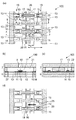
次に、図3を用いて第1の実施形態に係る液体吐出ヘッド100の構成について説明する。図3は、図2に示す液体吐出ヘッド100の発熱抵抗体10の周辺の構成を説明するための図である。図3(a)は液体吐出ヘッド100の一部を示す平面断面図、図3(b)は図3(a)のA−A’断面図、図3(c)は図3(a)のB−B’断面図、図3(d)は吸引回復時の液体の流れを説明するための図である。
First Embodiment
Next, the configuration of the
基板6には、吐出口8に対向して設けられ、液体を吐出するための熱エネルギーを発生する発熱抵抗体10が複数配列された発熱抵抗体列26が吐出口列9の方向に沿って設けられている。吐出口列9および発熱抵抗体列26は液体吐出ヘッド100の長手方向、すなわち基板6の長手方向に沿って設けられている。
The
また、吐出口列9の方向に隣接する発熱抵抗体10の間には隔壁20が設けられており、発熱抵抗体10が設けられた圧力室11がこの隔壁20によって区切られている。なお、本実施形態では、一例として、隔壁20の長さe(図3(a))が12μm、隔壁20の長さf(図3(a))が70μmである。
Further, a
基板6には、圧力室11に液体を供給するための供給口13が複数設けられ、この供給口13は吐出口列9の方向(発熱抵抗体列26の方向)に沿って配列されている。すなわち、この供給口13が配列して設けられた供給口列19は、基板6の長手方向に沿って設けられている。この供給口列19は、発熱抵抗体列26を挟むようにその両側にそれぞれ配置されている。なお、本実施態態では供給口13の形状は略矩形であり、一例として、基板6の表面において、供給口13の長さg(図3(a))は20μm、供給口13の長さh(図3(a))は40μmである。発熱抵抗体10の重心、すなわち、基板6の表面において一様に発熱抵抗体10の質量を分布させたときの質量中心と供給口13の発熱抵抗体10の側の端部との距離d(図3(a))は30μmである。
The
基板6と吐出口形成部材7とが接合されることで、圧力室11に対して両側に配置された供給口13同士を連通する液室21が設けられている(図3(b))。なお、一例として、発熱抵抗体10の重心と液室21を形成する壁の面との距離c(図3(a))は75μmである。
By joining the
次に、基板6の積層構成について説明する。図3(b)に示すように基板6の基体27は例えばシリコンで形成されており、基体27の表面には例えばSiO2やSiNの絶縁層14等が設けられている。さらに、基板6にはTaSiN等で形成された発熱抵抗体10が設けられており、この発熱抵抗体10は不図示の電極配線層と接続されている。この電極配線層は外部端子と電気的に接続されており、この電極配線層を介して発熱抵抗体10に電源を供給し、発熱抵抗体10を発熱させる。これにより、発熱抵抗体10に対応する熱作用部に接する液体が発泡して液体が吐出される。
Next, the laminated structure of the
発熱抵抗体10はSiN等で形成された絶縁層16で被覆されており、その吐出口形成部材7の側には例えばTaで形成された密着層17、さらには保護膜18が設けられている。1つの保護膜18が1つの発熱抵抗体10を被覆するように設けられている。密着層17は不図示の電極配線層を介して外部端子と電気的に接続されており、これにより、複数の保護膜18と外部端子とが電気的に接続されている。
The
なお、保護膜18は、比較的低いpH値の電解液でも溶出する特性を持つIrやRuといった白金族材料を用いることが好ましい。また、絶縁層16や密着層17は必ずしも設けられていなくてもよく、保護膜18が発熱抵抗体10を直接被覆してもよい。本実施形態では、保護膜18は1つの発熱抵抗体10の全ての部分を被覆しており、一例として、基板6の表面における保護膜18の大きさは20μm×20μmである。
The
図3(a)、(c)に示すように、基板6には、液体と保護膜18との間で電気化学反応を生じさせるための電極15が設けられている。電極15は、基板6の表面の、供給口列19の方向において互いに隣接する供給口13の間に設けられており、本実施形態では、電極15は隣接する供給口13間の中心に位置している。本実施形態では、一例として、基板6の表面における電極15の大きさは10μm×10μmである。なお、電極15も保護膜18と同じ材料を用いて形成することが好ましい。
As shown in FIGS. 3A and 3C, the
電極15は、不図示の外部端子と電気的に接続された例えばTaからなる電極配線層22と接続されている。これにより、電極15に外部から電源を供給することが可能となっており、すなわち、電極15は保護膜18との間に電圧を印加可能な構成となっている。液室21内に液体を充填したのち、保護膜18側が正、電極15側が負となるよう電圧を印加することで電気化学反応が起こり、液体と接触している保護膜18の表面が液体に溶出する。これにより、保護膜18の表面に堆積したコゲを除去することが可能となる。この液体は電解質を含んでいればよく、記録に用いられるインク等の液体を用いてもよい。
The
次に、本実施形態の効果を、図3〜図5を用いて説明する。図4、図5は、本実施形態の効果を説明するための比較例を示す図であり、図4(a)は比較例1の液体吐出ヘッド100の一部を示す平面断面図、図4(b)は図4(a)のA−A’断面図である。また、図5(a)は比較例2の液体吐出ヘッド100の一部を示す平面断面図、図5(b)は図5(a)のA−A’断面図であり、図5(c)は吸引回復時の液体の流れを説明するための図である。
Next, the effects of the present embodiment will be described with reference to FIGS. FIGS. 4 and 5 are views showing a comparative example for explaining the effect of the present embodiment, and FIG. 4A is a plan sectional view showing a part of the
図4では、大きさ10μm×10μmの電極15が供給口13と保護膜18との間に設けられており、電極15と保護膜18との最長の距離a(図4(a))は15μm、電極15と保護膜18との最短の距離b(図4(a))は5μmである。このため、電極15と保護膜18の電極15から最も遠い部分との間の電気抵抗は、電極15と保護膜18の電極15に最も近い部分との間の電気抵抗の約3倍程度になる。
In FIG. 4, an
ここで、保護膜18と電極15との距離とは、発熱抵抗体10と重複する保護膜18の領域と、この領域から最も近い位置に設けられた電極15の、この領域に最も近い箇所との距離であり、これが最長となる距離をa、最短となる距離をbとする。以下の説明においても同様とする。図4(a)に示す比較例1では、発熱抵抗体10の列に対してその両側に電極15が設けられた構成であるので、最長となる距離aは保護膜18の重心から電極15までの距離となる。
Here, the distance between the
電気化学反応により保護膜18の構成材料を液体に溶出させて保護膜18表面のコゲの除去動作を行うと、電極15から最も遠い保護膜18の重心の近傍部分では、保護膜18の電極15に最も近い部分と比べて保護膜18の溶出量が少なくなる。そのため、長時間液体吐出ヘッドを使用してコゲの除去動作を繰り返し行うと、保護膜18の厚みがその位置によって異なってしまい、液体に対する発熱抵抗体10の熱伝導が異なることになり、液体の吐出が不安定になる恐れがある。
When the constituent material of the
一方で、図5では、大きさ10μm×10μmの電極15が基板6の表面において供給口13の列に対して発熱抵抗体10の列とは反対側に設けられている。電極15と保護膜18との最長の距離a(図5(a))は75μm、電極15と保護膜18との最短の距離b(図5(a))は65μmである。このため、電極15と保護膜18の電極15から最も遠い部分との間の電気抵抗と、電極15と保護膜18の電極15に最も近い部分との間の電気抵抗との比の値は約1.15程度である。このように電気抵抗の比の値が小さくなり、保護膜18の位置による溶出量の差が小さくなるので、液体の吐出が不安定になるものではない。
On the other hand, in FIG. 5, an
しかし、図5のような位置に電極15を設けると、基板6の表面において吐出口列9の方向に直交する方向に基板6の長さが長くなってしまい、特に吐出口列9の数が多い場合には基板6の大型化、ひいてはコストの増加につながってしまう。例えば、図5では、発熱抵抗体10の重心と液室21を形成する壁の面との距離c(図5(a))が90μmとなり、図3の構成における距離cと比較して15μm長くなる。
However, when the
また、液体吐出ヘッド100に液体を充填する際や記録を繰り返し行った場合、液室21に泡24が取り込まれたり残留したりして、この泡24が電極15の設けられた領域に到達する場合がある。図5のような位置に電極15を設けた場合、吸引回復などで吐出口8から液体を吸引しても、図5(a)に示すように、供給口13からの液体の流れ25は電極15の表面を通りにくい。すると、図5(c)に示すように、電極15の表面に液体がほとんど流れ込まれずに泡24が抜けることがなく滞留し、電極15が液体に接触しなくなる恐れがある。この場合、保護膜18との間に適切に電圧を印加することができず、適切なコゲ除去動作が実現できない恐れがある。
Further, when the
そこで本実施形態では、上述したように、電極15は、基板6の表面の、供給口列19の方向に隣接する供給口13の間に設けられている。一例として、電極15と保護膜18との最長の距離a(図3(a))は43μm、電極15と保護膜18との最短の距離b(図3(a))は36μmであり、これらの電気抵抗の比の値は約1.19程度と、図5の構成と同等にまで低減される。このため、保護膜18の位置による溶出量の差が小さくなる。また、図5の例のように基板6の表面において吐出口列9の方向に直交する方向に基板6の長さが長くなることも抑制される。さらに、吸引回復時には、図3(d)に示すように、電極15の表面に液体の流れが生じるため、泡が発生しても電極15の表面で滞留することが抑制され、泡だまりによってコゲ除去動作が適切に行われない恐れも低減される。
Therefore, in the present embodiment, as described above, the
このように本実施形態によると、供給口13と圧力室11を近づけて圧力室11への液体の再充填を高速化し高速印字を実現しつつ、保護膜の溶出量の差を低減できるよう保護膜18と電極15の距離を確保しているので、安定した吐出状態を維持できる。また、液体吐出ヘッド用基板6の大型化を抑制することが可能となる。さらに、泡だまりによってコゲ除去動作が妨げられる恐れを低減することが可能となる。
As described above, according to the present embodiment, the
なお、電極15と保護膜18との距離に関して、上述した最長の距離aと最短の距離bとの関係が1<a/b≦2となるように電極15を設けることがより望ましい。これにより、長時間にわたって液体吐出ヘッド100を使用しコゲ除去動作を繰り返し行っても、保護膜18の位置による溶出量の差による影響をほとんど無視できる程度にすることができるためである。
It is more preferable to provide the
また、発熱抵抗体10は、絶縁層14に形成された不図示のスルーホールに挿通され、絶縁層14中に形成されたAl、Al−Si、Al−Cu等の金属材料からなる電極配線層に接続されることが望ましい。このような構成とすることで、発熱抵抗体10に接続される配線を基板6の表面の供給口13の間の領域に設けずに済むため、供給口13の間に電極15を配置する領域を確保しやすくなる。
In addition, the
また、発熱抵抗体10の列に交差する方向における基板6の小型化の観点からは、図3(a)に示すように、供給口13の、発熱抵抗体10の列から最も離れた部分よりも発熱抵抗体10の列に寄った位置に電極15が設けられていることが好ましい。すなわち、電極15が発熱抵抗体列26から離れる方向に供給口13の間からはみ出さないように設けられていることが好ましい。
Further, from the viewpoint of reducing the size of the
また、図6(a)に示すように、電極15の重心Cが、配列方向の両側に設けられた供給口13の重心を結ぶ直線lよりも発熱抵抗体10の列に寄った位置に位置するように、電極15が設けられていることが望ましい。これにより、吸引回復や液体の再充填の際に供給口13から吐出口8に向かう流れ25が電極15の表面を通り易くなり、上述した泡だまりの発生をより抑えることが可能となる。
Further, as shown in FIG. 6A, the position of the center of gravity C of the
一方で、保護膜18と電極15の距離を確保する観点からは、図6(b)のように、電極15の重心Cが、配列方向の両側の供給口13の重心を結ぶ直線lよりも発熱抵抗体10の列から離れた位置に位置するように、電極15が設けられていることが好ましい。
On the other hand, from the viewpoint of securing the distance between the
また、電極15はその全ての部分が供給口13の間に位置していなくてもよく、電極15の少なくとも一部が供給口13の配列方向における供給口13の間に位置していればよい。
In addition, it is not necessary for all the portions of the
また、電極15は、供給口列19を構成する供給口13のそれぞれの間に設けられていることがより好ましい。これにより、保護膜18に対してより均一にコゲの除去を行うことができるためである。
Further, the
(第2の実施形態)
次に、図7を用いて第2の実施形態について説明する。なお、上述の実施形態と同様に構成される部分については図中同一符号を付して説明を省略し、異なる部分について説明する。
Second Embodiment
Next, a second embodiment will be described using FIG. In addition, about the part comprised similarly to the above-mentioned embodiment, the code | symbol same in a figure is attached | subjected, description is abbreviate | omitted, and a different part is demonstrated.
上述の実施形態では一列の発熱抵抗体10の列に対してその両側に供給口13の列が設けられた構成であったが、本実施形態では一列の発熱抵抗体10の列に対して片側に一列の供給口13の列が設けられた構成である。なお、本実施形態では、上述した電極15と保護膜18との最長の距離a、最短の距離bは、図7に示す通りとなる。
In the embodiment described above, the rows of the
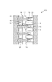
(第3の実施形態)
次に、図8を用いて第3の実施形態について説明する。なお、上述の実施形態と同様に構成される部分については図中同一符号を付して説明を省略し、異なる部分について説明する。
Third Embodiment
Next, a third embodiment will be described using FIG. In addition, about the part comprised similarly to the above-mentioned embodiment, the code | symbol same in a figure is attached | subjected, description is abbreviate | omitted, and a different part is demonstrated.
本実施形態では、上述の実施形態と比べて供給口列を構成する供給口13の数を少なくしている。すなわち、上述の実施形態では1つの供給口13が発熱抵抗体10のそれぞれに隣接するように供給口13を設けていたが、本実施形態では1つの供給口13が複数の発熱抵抗体10に隣接するように供給口13を設けている。具体的には、本実施形態では、一つの供給口13に対して二つの流路12が接続されており、一つの供給口13から主に二つの圧力室11に液体が供給される構成である。高速記録を実現するためには、吐出口8から液体を吐出させた後、圧力室11に液体をすばやく再充填する必要があり、圧力室11と供給口13に近づけることに加え、供給口13の圧力損失が小さい方が好ましい。
In the present embodiment, the number of
ここで、略矩形状の管路の圧力損失は、そのアスペクト比が小さいほど小さくなる。例えば本実施形態では、供給口13の長さjが40μm、長さiが30μm(図8)で供給口13は二つの流路12と接続されている。一方で、上述の実施形態では、供給口13の長さgが20μm、供給口13の長さhが40μm(図3(a))で供給口13は一つの流路12と接続されている。両者の構成においてその圧力損失はほぼ同程度である。
Here, the pressure loss of the substantially rectangular pipe decreases as the aspect ratio decreases. For example, in the present embodiment, the
このように、一つの供給口13に複数の流路12を接続することで、供給口13の圧力損失を大きくなることを抑えつつ、供給口13の配列方向に交差する方向(本実施形態では配列方向に直交する方向)の供給口13のサイズを小さくすることができる。
As described above, by connecting the plurality of
なお、図8では一つの供給口13に液室21を介して二つの流路12が接続されているが、接続される流路12は三つ以上であってもよい。
Although two
(第4の実施形態)
次に、図9を用いて第4の実施形態について説明する。なお、上述の実施形態と同様に構成される部分については図中同一符号を付して説明を省略し、異なる部分について説明する。
Fourth Embodiment
Next, a fourth embodiment will be described using FIG. In addition, about the part comprised similarly to the above-mentioned embodiment, the code | symbol same in a figure is attached | subjected, description is abbreviate | omitted, and a different part is demonstrated.
本実施形態では、発熱抵抗体10の重心Hとこの発熱抵抗体10の最も近くに位置する電極15の重心Cとが発熱抵抗体列26に直交する方向において横並びに位置している。すなわち、基板6の表面において発熱抵抗体10の重心Hと電極15の重心Cとを結ぶ直線が、発熱抵抗体列26に直交する方向に平行になるように、電極15が設けられている。また、発熱抵抗体10の重心Hと供給口13の重心Sとを結ぶ直線は、発熱抵抗体列26に直交する方向に交差している。
In the present embodiment, the center of gravity H of the
本実施形態においても、電極15は供給口13の配列方向において隣接する供給口13の間に位置しており、保護膜18の溶出量の差を低減できるように保護膜18と電極15の距離を確保しているので、安定した吐出状態を維持することができる。また、供給口13の配列方向に交差する方向における液体吐出ヘッド用基板6の大型化を抑制することが可能となる。
Also in this embodiment, the
なお、保護膜18と電極15との距離をより長くする観点からは、本実施形態のような電極15の配置よりも、上述の実施形態のような電極15の配置の方がより好ましい。すなわち、上述の実施形態のように、発熱抵抗体10の重心とこの発熱抵抗体10の最も近くに位置する電極15の重心とが発熱抵抗体列26に直交する方向においてずれて位置することがより好ましい。
From the viewpoint of further increasing the distance between the
(その他の実施形態)
次に、図10を用いてその他の実施形態について説明する。なお、上述の実施形態と同様に構成される部分については図中同一符号を付して説明を省略し、異なる部分について説明する。
(Other embodiments)
Next, another embodiment will be described using FIG. In addition, about the part comprised similarly to the above-mentioned embodiment, the code | symbol same in a figure is attached | subjected, description is abbreviate | omitted, and a different part is demonstrated.
図10(a)〜(c)に示す実施形態では、電極15が設置されている供給口13の間に、吐出口形成部材7と基板6とを接続する接続部としての柱状部材23が設けられている。上述の実施形態では基板6の表面の供給口13間の領域は吐出口形成部材7から離れており、このように吐出口形成部材7と基板6とが接していない部分の距離が長いと、液体吐出ヘッド100が割れたり変形したりする恐れがある。
In the embodiment shown in FIGS. 10 (a) to 10 (c), a
そこで、本実施形態では、供給口13の間に柱状部材23を設けることで、電極15の表面を通る吐出口8と供給口13との液体の流れを確保しつつ、液体吐出ヘッド100の信頼性を向上することができる。なお、柱状部材23は、図10(a)のように独立した複数の部材で設けられていても、図10(b)のように壁状であってもよい。
Therefore, in the present embodiment, by providing the
また、図10(a)、(b)は電極15の表面に柱状部材23を設ける構成であるが、コゲ除去動作に用いられる電極15の面積を確保するために、図10(c)のように、柱状部材23を電極15が設けられていない供給口13の間の領域に設けてもよい。また、供給口13の配列方向に複数の柱状部材23を配置してもよい。
10 (a) and 10 (b) show a configuration in which the
6 基板(液体吐出ヘッド用基板)
10 発熱抵抗体
13 供給口
15 電極
18 保護膜
6 Substrate (substrate for liquid discharge head)
Claims (19)
前記発熱抵抗体を覆う保護膜と、
を有する液体吐出ヘッド用基板であって、
前記液体吐出ヘッド用基板の前記保護膜が設けられる面の側に設けられ、液体を流すための複数の開口が前記発熱抵抗体列の方向に沿って配列された開口列と、
前記面の側に設けられ、前記保護膜との間に電圧を印加可能な電極と、
を有し、
前記電極は少なくとも一部が前記開口列の方向において隣接する前記開口の間に位置することを特徴とする液体吐出ヘッド用基板。 A heating resistor row in which a plurality of heating resistors are arranged,
A protective film covering the heat generating resistor;
A substrate for a liquid discharge head having
Provided on the side surface of the protective layer of the substrate for the liquid discharge head is provided, and the opening sequence in which a plurality of openings of Sutame flow of liquid are arranged along the direction of the heating resistor string,
An electrode provided on the side of the surface, to which a voltage can be applied between the electrode and the protective film;
I have a,
At least a part of the electrode is located between the adjacent openings in the direction of the opening row .
前記電極と前記外部端子とを接続するための配線と、A wire for connecting the electrode and the external terminal;
を有する、請求項1乃至請求項12のいずれか一項に記載の液体吐出ヘッド用基板。The liquid discharge head substrate according to any one of claims 1 to 12, which has
を有する液体吐出ヘッド用基板と、
液体を吐出する吐出口が形成された吐出口形成部材と、
を有し、
前記液体吐出ヘッド用基板の前記保護膜が設けられる面の側に設けられ、液体を流すための複数の開口が前記発熱抵抗体列の方向に沿って配列された開口列と、
前記面の側に設けられ、前記保護膜との間に電圧を印加可能な電極と、
を有し、
前記電極は少なくとも一部が前記開口列の方向において隣接する前記開口の間に位置することを特徴とする液体吐出ヘッド。 A heating resistor row in which a plurality of heating resistors are arranged; a protective film covering the heating resistors;
A substrate for a liquid discharge head having
A discharge port forming member in which a discharge port for discharging a liquid is formed;
Have
Provided on the side surface of the protective layer of the substrate for the liquid discharge head is provided, and the opening sequence in which a plurality of openings for the flow of liquid are arranged along the direction of the heating resistor string,
An electrode provided on the side of the surface, to which a voltage can be applied between the electrode and the protective film;
I have a,
The liquid discharge head, wherein the electrodes are at least partially located between the adjacent openings in the direction of the opening row .
Priority Applications (3)
| Application Number | Priority Date | Filing Date | Title |
|---|---|---|---|
| JP2015128154A JP6504938B2 (en) | 2015-06-25 | 2015-06-25 | Substrate for liquid discharge head and liquid discharge head |
| US15/188,571 US9764550B2 (en) | 2015-06-25 | 2016-06-21 | Liquid ejection head substrate and liquid ejection head |
| US15/677,697 US9981470B2 (en) | 2015-06-25 | 2017-08-15 | Liquid ejection head substrate and liquid ejection head |
Applications Claiming Priority (1)
| Application Number | Priority Date | Filing Date | Title |
|---|---|---|---|
| JP2015128154A JP6504938B2 (en) | 2015-06-25 | 2015-06-25 | Substrate for liquid discharge head and liquid discharge head |
Publications (3)
| Publication Number | Publication Date |
|---|---|
| JP2017007295A JP2017007295A (en) | 2017-01-12 |
| JP2017007295A5 JP2017007295A5 (en) | 2018-07-19 |
| JP6504938B2 true JP6504938B2 (en) | 2019-04-24 |
Family
ID=57605241
Family Applications (1)
| Application Number | Title | Priority Date | Filing Date |
|---|---|---|---|
| JP2015128154A Active JP6504938B2 (en) | 2015-06-25 | 2015-06-25 | Substrate for liquid discharge head and liquid discharge head |
Country Status (2)
| Country | Link |
|---|---|
| US (2) | US9764550B2 (en) |
| JP (1) | JP6504938B2 (en) |
Cited By (1)
| Publication number | Priority date | Publication date | Assignee | Title |
|---|---|---|---|---|
| EP4393714A1 (en) * | 2022-12-27 | 2024-07-03 | Canon Kabushiki Kaisha | Liquid ejection device |
Families Citing this family (4)
| Publication number | Priority date | Publication date | Assignee | Title |
|---|---|---|---|---|
| JP6504938B2 (en) * | 2015-06-25 | 2019-04-24 | キヤノン株式会社 | Substrate for liquid discharge head and liquid discharge head |
| JP6878153B2 (en) * | 2017-06-02 | 2021-05-26 | キヤノン株式会社 | Liquid discharge head, liquid discharge head cleaning method and liquid discharge device |
| JP6918636B2 (en) * | 2017-08-22 | 2021-08-11 | キヤノン株式会社 | Control method for liquid discharge head substrate, liquid discharge head, liquid discharge device, and liquid discharge head |
| JP7346119B2 (en) * | 2019-07-16 | 2023-09-19 | キヤノン株式会社 | Liquid ejection head cleaning method and liquid ejection device |
Family Cites Families (9)
| Publication number | Priority date | Publication date | Assignee | Title |
|---|---|---|---|---|
| US6003977A (en) * | 1996-02-07 | 1999-12-21 | Hewlett-Packard Company | Bubble valving for ink-jet printheads |
| JP4926669B2 (en) * | 2005-12-09 | 2012-05-09 | キヤノン株式会社 | Inkjet head cleaning method, inkjet head, and inkjet recording apparatus |
| JP4656670B2 (en) * | 2008-12-19 | 2011-03-23 | キヤノン株式会社 | Liquid discharge head and method of manufacturing liquid discharge head |
| US8210654B2 (en) * | 2010-05-28 | 2012-07-03 | Hewlett-Packard Development Company, L.P. | Fluid ejection device with electrodes to generate electric field within chamber |
| JP5826008B2 (en) * | 2011-12-02 | 2015-12-02 | キヤノン株式会社 | Ink jet recording head, and recording method and suction method using the ink jet recording head |
| JP6039411B2 (en) * | 2012-12-27 | 2016-12-07 | キヤノン株式会社 | Inkjet head substrate, inkjet head, and inkjet head manufacturing method |
| JP6222968B2 (en) * | 2013-04-09 | 2017-11-01 | キヤノン株式会社 | Liquid discharge head, liquid discharge head cleaning method, and liquid discharge apparatus |
| JP6300486B2 (en) * | 2013-10-18 | 2018-03-28 | キヤノン株式会社 | Liquid discharge head and liquid discharge apparatus |
| JP6504938B2 (en) * | 2015-06-25 | 2019-04-24 | キヤノン株式会社 | Substrate for liquid discharge head and liquid discharge head |
-
2015
- 2015-06-25 JP JP2015128154A patent/JP6504938B2/en active Active
-
2016
- 2016-06-21 US US15/188,571 patent/US9764550B2/en not_active Expired - Fee Related
-
2017
- 2017-08-15 US US15/677,697 patent/US9981470B2/en active Active
Cited By (1)
| Publication number | Priority date | Publication date | Assignee | Title |
|---|---|---|---|---|
| EP4393714A1 (en) * | 2022-12-27 | 2024-07-03 | Canon Kabushiki Kaisha | Liquid ejection device |
Also Published As
| Publication number | Publication date |
|---|---|
| US9764550B2 (en) | 2017-09-19 |
| US20170341385A1 (en) | 2017-11-30 |
| US20160375685A1 (en) | 2016-12-29 |
| US9981470B2 (en) | 2018-05-29 |
| JP2017007295A (en) | 2017-01-12 |
Similar Documents
| Publication | Publication Date | Title |
|---|---|---|
| JP6504938B2 (en) | Substrate for liquid discharge head and liquid discharge head | |
| US6491377B1 (en) | High print quality printhead | |
| JP5569092B2 (en) | Liquid ejecting head, liquid ejecting head unit, and liquid ejecting apparatus | |
| WO2015147804A1 (en) | Printhead fluid passageway thin film passivation layer | |
| US9216575B2 (en) | Recording-element substrate and liquid ejection apparatus | |
| JP2011515237A (en) | Double feed droplet ejector | |
| JP4900486B2 (en) | Ink jet head and electrostatic suction type ink jet head | |
| US20120019597A1 (en) | Inkjet printhead with cross-slot conductor routing | |
| CN109421372B (en) | Liquid discharge head, method of controlling the same, liquid discharge head substrate, and apparatus | |
| JP2016210070A (en) | Substrate for ink jet recording head | |
| JP7190278B2 (en) | LIQUID EJECTOR AND CONTROL METHOD THEREOF | |
| JP2013163355A (en) | Liquid discharging recording head | |
| JP2016182807A (en) | Liquid discharge head cleaning method | |
| JP2011213049A (en) | Liquid discharge head and driving method of the same | |
| JP2022514711A (en) | Die for printhead | |
| KR20090131296A (en) | Inkjet printhead with low voltage ink vaporizing heaters | |
| JP6222968B2 (en) | Liquid discharge head, liquid discharge head cleaning method, and liquid discharge apparatus | |
| JP7134733B2 (en) | PRINTING ELEMENT SUBSTRATE, LIQUID EJECTION HEAD, AND LIQUID EJECTION APPARATUS | |
| JP2016055577A (en) | Passage member, liquid injection head, liquid injection device and liquid agitation method | |
| JP2012152902A (en) | Liquid discharge head substrate | |
| JP7346119B2 (en) | Liquid ejection head cleaning method and liquid ejection device | |
| JP7023650B2 (en) | Liquid discharge head and its manufacturing method | |
| JP6685736B2 (en) | Inkjet head | |
| JP6312547B2 (en) | Inkjet head and printer | |
| JP2024093460A (en) | Liquid ejection device |
Legal Events
| Date | Code | Title | Description |
|---|---|---|---|
| A521 | Request for written amendment filed |
Free format text: JAPANESE INTERMEDIATE CODE: A523 Effective date: 20180605 |
|
| A621 | Written request for application examination |
Free format text: JAPANESE INTERMEDIATE CODE: A621 Effective date: 20180605 |
|
| A977 | Report on retrieval |
Free format text: JAPANESE INTERMEDIATE CODE: A971007 Effective date: 20190207 |
|
| TRDD | Decision of grant or rejection written | ||
| A01 | Written decision to grant a patent or to grant a registration (utility model) |
Free format text: JAPANESE INTERMEDIATE CODE: A01 Effective date: 20190226 |
|
| A61 | First payment of annual fees (during grant procedure) |
Free format text: JAPANESE INTERMEDIATE CODE: A61 Effective date: 20190326 |
|
| R151 | Written notification of patent or utility model registration |
Ref document number: 6504938 Country of ref document: JP Free format text: JAPANESE INTERMEDIATE CODE: R151 |