JP6504905B2 - Liquid discharge head, method of cleaning the head, and recording apparatus - Google Patents
Liquid discharge head, method of cleaning the head, and recording apparatus Download PDFInfo
- Publication number
- JP6504905B2 JP6504905B2 JP2015095647A JP2015095647A JP6504905B2 JP 6504905 B2 JP6504905 B2 JP 6504905B2 JP 2015095647 A JP2015095647 A JP 2015095647A JP 2015095647 A JP2015095647 A JP 2015095647A JP 6504905 B2 JP6504905 B2 JP 6504905B2
- Authority
- JP
- Japan
- Prior art keywords
- liquid
- electrode
- liquid discharge
- discharge head
- cleaning
- Prior art date
- Legal status (The legal status is an assumption and is not a legal conclusion. Google has not performed a legal analysis and makes no representation as to the accuracy of the status listed.)
- Active
Links
- 239000007788 liquid Substances 0.000 title claims description 235
- 238000004140 cleaning Methods 0.000 title claims description 87
- 238000000034 method Methods 0.000 title claims description 48
- 238000010438 heat treatment Methods 0.000 claims description 44
- 239000011241 protective layer Substances 0.000 claims description 37
- 239000000463 material Substances 0.000 claims description 34
- 238000003487 electrochemical reaction Methods 0.000 claims description 27
- 229910052751 metal Inorganic materials 0.000 claims description 14
- 239000002184 metal Substances 0.000 claims description 14
- 238000010828 elution Methods 0.000 claims description 10
- 238000006243 chemical reaction Methods 0.000 claims description 9
- 230000000903 blocking effect Effects 0.000 claims description 6
- 229910052715 tantalum Inorganic materials 0.000 claims description 5
- 229910052758 niobium Inorganic materials 0.000 claims description 4
- 239000006260 foam Substances 0.000 claims 2
- 239000010410 layer Substances 0.000 description 43
- 239000001257 hydrogen Substances 0.000 description 25
- 229910052739 hydrogen Inorganic materials 0.000 description 25
- UFHFLCQGNIYNRP-UHFFFAOYSA-N Hydrogen Chemical compound [H][H] UFHFLCQGNIYNRP-UHFFFAOYSA-N 0.000 description 23
- 238000011084 recovery Methods 0.000 description 17
- 239000000758 substrate Substances 0.000 description 13
- 238000002474 experimental method Methods 0.000 description 9
- 238000005336 cracking Methods 0.000 description 6
- 229910052741 iridium Inorganic materials 0.000 description 6
- 239000000126 substance Substances 0.000 description 6
- 230000005587 bubbling Effects 0.000 description 5
- 230000006866 deterioration Effects 0.000 description 5
- 238000007599 discharging Methods 0.000 description 5
- 230000006870 function Effects 0.000 description 5
- 238000010586 diagram Methods 0.000 description 4
- 125000004435 hydrogen atom Chemical group [H]* 0.000 description 4
- 229910052707 ruthenium Inorganic materials 0.000 description 4
- 229910004298 SiO 2 Inorganic materials 0.000 description 3
- 230000015572 biosynthetic process Effects 0.000 description 3
- 239000003086 colorant Substances 0.000 description 3
- 230000008021 deposition Effects 0.000 description 3
- 238000005338 heat storage Methods 0.000 description 3
- 239000012535 impurity Substances 0.000 description 3
- GKOZUEZYRPOHIO-UHFFFAOYSA-N iridium atom Chemical compound [Ir] GKOZUEZYRPOHIO-UHFFFAOYSA-N 0.000 description 3
- 239000007769 metal material Substances 0.000 description 3
- 239000010955 niobium Substances 0.000 description 3
- 229910004200 TaSiN Inorganic materials 0.000 description 2
- 229910045601 alloy Inorganic materials 0.000 description 2
- 239000000956 alloy Substances 0.000 description 2
- 230000000694 effects Effects 0.000 description 2
- 238000005187 foaming Methods 0.000 description 2
- 150000002431 hydrogen Chemical class 0.000 description 2
- 239000011810 insulating material Substances 0.000 description 2
- 239000008258 liquid foam Substances 0.000 description 2
- 239000004065 semiconductor Substances 0.000 description 2
- 238000000926 separation method Methods 0.000 description 2
- GUVRBAGPIYLISA-UHFFFAOYSA-N tantalum atom Chemical compound [Ta] GUVRBAGPIYLISA-UHFFFAOYSA-N 0.000 description 2
- 229910018125 Al-Si Inorganic materials 0.000 description 1
- 229910018182 Al—Cu Inorganic materials 0.000 description 1
- 229910018520 Al—Si Inorganic materials 0.000 description 1
- 229910000575 Ir alloy Inorganic materials 0.000 description 1
- 206010037660 Pyrexia Diseases 0.000 description 1
- 229910000929 Ru alloy Inorganic materials 0.000 description 1
- KJTLSVCANCCWHF-UHFFFAOYSA-N Ruthenium Chemical compound [Ru] KJTLSVCANCCWHF-UHFFFAOYSA-N 0.000 description 1
- 229910052581 Si3N4 Inorganic materials 0.000 description 1
- 238000009825 accumulation Methods 0.000 description 1
- 239000000654 additive Substances 0.000 description 1
- 239000000853 adhesive Substances 0.000 description 1
- 230000001070 adhesive effect Effects 0.000 description 1
- 239000003513 alkali Substances 0.000 description 1
- 229910052782 aluminium Inorganic materials 0.000 description 1
- 230000005540 biological transmission Effects 0.000 description 1
- 238000004040 coloring Methods 0.000 description 1
- 230000000052 comparative effect Effects 0.000 description 1
- 239000002131 composite material Substances 0.000 description 1
- 239000004020 conductor Substances 0.000 description 1
- 230000008602 contraction Effects 0.000 description 1
- 230000007423 decrease Effects 0.000 description 1
- 238000001514 detection method Methods 0.000 description 1
- 239000008151 electrolyte solution Substances 0.000 description 1
- 238000005530 etching Methods 0.000 description 1
- 230000002349 favourable effect Effects 0.000 description 1
- 230000020169 heat generation Effects 0.000 description 1
- -1 hydrogen ions Chemical class 0.000 description 1
- 238000009413 insulation Methods 0.000 description 1
- 238000010030 laminating Methods 0.000 description 1
- 238000004519 manufacturing process Methods 0.000 description 1
- 150000002739 metals Chemical class 0.000 description 1
- GUCVJGMIXFAOAE-UHFFFAOYSA-N niobium atom Chemical compound [Nb] GUCVJGMIXFAOAE-UHFFFAOYSA-N 0.000 description 1
- 238000002161 passivation Methods 0.000 description 1
- 230000000149 penetrating effect Effects 0.000 description 1
- 230000002093 peripheral effect Effects 0.000 description 1
- 238000010926 purge Methods 0.000 description 1
- 229910052710 silicon Inorganic materials 0.000 description 1
- 239000010703 silicon Substances 0.000 description 1
- HQVNEWCFYHHQES-UHFFFAOYSA-N silicon nitride Chemical compound N12[Si]34N5[Si]62N3[Si]51N64 HQVNEWCFYHHQES-UHFFFAOYSA-N 0.000 description 1
- 238000003860 storage Methods 0.000 description 1
- 238000011144 upstream manufacturing Methods 0.000 description 1
Images


Classifications
-
- B—PERFORMING OPERATIONS; TRANSPORTING
- B41—PRINTING; LINING MACHINES; TYPEWRITERS; STAMPS
- B41J—TYPEWRITERS; SELECTIVE PRINTING MECHANISMS, i.e. MECHANISMS PRINTING OTHERWISE THAN FROM A FORME; CORRECTION OF TYPOGRAPHICAL ERRORS
- B41J2/00—Typewriters or selective printing mechanisms characterised by the printing or marking process for which they are designed
- B41J2/005—Typewriters or selective printing mechanisms characterised by the printing or marking process for which they are designed characterised by bringing liquid or particles selectively into contact with a printing material
- B41J2/01—Ink jet
- B41J2/135—Nozzles
- B41J2/14—Structure thereof only for on-demand ink jet heads
- B41J2/14016—Structure of bubble jet print heads
- B41J2/14088—Structure of heating means
- B41J2/14112—Resistive element
- B41J2/14129—Layer structure
-
- B—PERFORMING OPERATIONS; TRANSPORTING
- B41—PRINTING; LINING MACHINES; TYPEWRITERS; STAMPS
- B41J—TYPEWRITERS; SELECTIVE PRINTING MECHANISMS, i.e. MECHANISMS PRINTING OTHERWISE THAN FROM A FORME; CORRECTION OF TYPOGRAPHICAL ERRORS
- B41J2/00—Typewriters or selective printing mechanisms characterised by the printing or marking process for which they are designed
- B41J2/005—Typewriters or selective printing mechanisms characterised by the printing or marking process for which they are designed characterised by bringing liquid or particles selectively into contact with a printing material
- B41J2/01—Ink jet
- B41J2/135—Nozzles
- B41J2/14—Structure thereof only for on-demand ink jet heads
- B41J2/14016—Structure of bubble jet print heads
- B41J2/14072—Electrical connections, e.g. details on electrodes, connecting the chip to the outside...
-
- B—PERFORMING OPERATIONS; TRANSPORTING
- B41—PRINTING; LINING MACHINES; TYPEWRITERS; STAMPS
- B41J—TYPEWRITERS; SELECTIVE PRINTING MECHANISMS, i.e. MECHANISMS PRINTING OTHERWISE THAN FROM A FORME; CORRECTION OF TYPOGRAPHICAL ERRORS
- B41J2/00—Typewriters or selective printing mechanisms characterised by the printing or marking process for which they are designed
- B41J2/005—Typewriters or selective printing mechanisms characterised by the printing or marking process for which they are designed characterised by bringing liquid or particles selectively into contact with a printing material
- B41J2/01—Ink jet
- B41J2/135—Nozzles
- B41J2/165—Prevention or detection of nozzle clogging, e.g. cleaning, capping or moistening for nozzles
-
- B—PERFORMING OPERATIONS; TRANSPORTING
- B41—PRINTING; LINING MACHINES; TYPEWRITERS; STAMPS
- B41J—TYPEWRITERS; SELECTIVE PRINTING MECHANISMS, i.e. MECHANISMS PRINTING OTHERWISE THAN FROM A FORME; CORRECTION OF TYPOGRAPHICAL ERRORS
- B41J2/00—Typewriters or selective printing mechanisms characterised by the printing or marking process for which they are designed
- B41J2/005—Typewriters or selective printing mechanisms characterised by the printing or marking process for which they are designed characterised by bringing liquid or particles selectively into contact with a printing material
- B41J2/01—Ink jet
- B41J2/135—Nozzles
- B41J2/14—Structure thereof only for on-demand ink jet heads
- B41J2/14016—Structure of bubble jet print heads
- B41J2/14032—Structure of the pressure chamber
- B41J2/14056—Plural heating elements per ink chamber
Landscapes
- Ink Jet (AREA)
- Particle Formation And Scattering Control In Inkjet Printers (AREA)
Description
本発明は、液体吐出方式によりインクを吐出して記録媒体に記録を行うための液体吐出ヘッド及び該ヘッドのクリーニング方法に関するものである。また、本発明は、該ヘッドを備える記録装置に関する。 The present invention relates to a liquid discharge head for discharging ink by a liquid discharge method to perform recording on a recording medium, and a method of cleaning the head. The present invention also relates to a recording apparatus provided with the head.
液体吐出方式(インクジェット記録方式)は、液体吐出ヘッドに設けられた吐出口から液体(例えばインク)を吐出させ、これを紙などの被記録材に付着させて記録を行うものである。電気熱変換素子が発生する熱エネルギーにより生ずる液体の発泡を利用して液体を吐出する方式のインクジェット記録方式は、高画質及び高速記録が可能である。 In the liquid discharge method (ink jet recording method), a liquid (for example, ink) is discharged from a discharge port provided in a liquid discharge head, and this is adhered to a recording material such as paper to perform recording. The inkjet recording method of the system which discharges a liquid using foaming of the liquid which generate | occur | produces with the heat energy which an electrothermal transducer generate | occur | produces enables high quality image and high-speed recording.
この種の液体吐出ヘッドの一般的な構成は、複数の吐出口と、この吐出口に連通する流路と、インクを吐出するために利用される熱エネルギーを発生する複数の電気熱変換素子とを有する。そして、電気熱変換素子は発熱抵抗体及びこれに電力を供給するための電極によって構成され、この電気熱変換素子が、例えば窒化珪素などの絶縁性をもつ下部保護層により被覆されることで、インクと電気熱変換素子間での絶縁性が確保される。 A general configuration of a liquid discharge head of this type includes a plurality of discharge ports, a flow path communicating with the discharge ports, and a plurality of electrothermal conversion elements that generate thermal energy used to discharge ink. Have. The electrothermal transducer is constituted by a heating resistor and an electrode for supplying power thereto, and the electrothermal transducer is covered with a lower protective layer having an insulating property such as silicon nitride, for example. The insulation between the ink and the electrothermal transducer is secured.
液体吐出時における電気熱変換素子の発熱部は、高温に曝されるとともに、液体の発泡、収縮に伴うキャビテーション衝撃やインクによる化学的作用を複合的に受けることになる。このため発熱部には、キャビテーションによる衝撃やインクによる化学的作用から発熱抵抗体を保護するため、上部保護層が設けられる。この上部保護層の表面は700℃付近まで昇温し、かつインクに接する為、耐熱性、機械的特性、化学的安定性、耐アルカリ性等に優れた膜特性が要求される。 The heat generating portion of the electrothermal transducer at the time of liquid discharge is exposed to a high temperature, and is subjected to a composite impact of the cavitation impact accompanying the bubbling and contraction of the liquid and the ink. For this reason, in the heat generating portion, an upper protective layer is provided in order to protect the heat generating resistor from the impact of cavitation and the chemical action by the ink. Since the surface of the upper protective layer is heated to about 700 ° C. and in contact with the ink, film properties excellent in heat resistance, mechanical properties, chemical stability, alkali resistance and the like are required.
また、インクに含まれる色材及び添加物などが高温加熱により分子レベルで分解され、「コゲ」と呼ばれる難溶解性の物質に変化する現象が生じる。このコゲが上部保護層上に物理吸着すると、発熱抵抗体からインクへの熱伝導が不均一になり、吐出したインクの速度が低下する、発泡が不安定になる、吐出に必要なエネルギーが増加するといった問題が生じる。 In addition, coloring materials and additives contained in the ink are decomposed at the molecular level by high temperature heating, and a phenomenon occurs in which the substance is changed to a poorly soluble substance called "koge". When the bark physically adsorbs on the upper protective layer, the heat conduction from the heat generating resistor to the ink becomes uneven, the speed of the discharged ink decreases, the bubbling becomes unstable, and the energy required for the discharge increases. Problems will arise.
そこで、特許文献1には、上部保護層の表面をイリジウムやルテニウムなどの電気化学反応によって溶出可能な材料で構成することで、コゲを除去する技術が開示されている。
Therefore,
特許文献1に示されるコゲ除去のクリーニング方法は、電気化学反応を利用したものである。つまり、溶出可能な材料で形成された上部保護層をアノード電極とし、液体を介して導通可能な位置に配置された対向電極をカソード電極として、両電極間に電圧を印加することにより、液体中へ該材料を溶出させると同時にコゲを除去している。
The cleaning method for removing kogation shown in
このとき、対向電極においては、液体中の水素イオンが還元され水素原子となり、二つの水素原子が再結合することにより、水素ガスが発生する。ここで、水素原子が、スムースに再結合し系外へ排出されれば問題はない。しかしながら、水素の発生スピードが速くなったり、発生時間が長くなったりしてこの排出過程が律速する。このような場合、対向電極や、対向電極に電気的に接続された配線を形成する材料内へ水素原子が吸収され、これら材料の中で再結合し、水素脆化と呼ばれる材料劣化を引き起こし易くなる。水素脆化の問題は排出過程の律速に拘わらず、クリーニング回数の増加によっても起こり得る。コゲ除去を何回か繰り返すうちに材料の劣化部分は割れるなどして断線し、クリーニング動作ができなくなり、アノード電極が残存しているにも拘わらず、ヘッド寿命となる。したがって、予定していたヘッド寿命よりも早期にヘッド寿命がきてしまうことになる。 At this time, in the counter electrode, hydrogen ions in the liquid are reduced to be hydrogen atoms, and two hydrogen atoms are recombined to generate hydrogen gas. Here, there is no problem if hydrogen atoms recombine smoothly and are discharged out of the system. However, the discharge process becomes rate-limited because the generation speed of hydrogen increases or the generation time increases. In such a case, hydrogen atoms are absorbed into the material forming the counter electrode or the wiring electrically connected to the counter electrode, and are recombined among these materials, which tends to cause deterioration of the material called hydrogen embrittlement. Become. The problem of hydrogen embrittlement can also occur with an increase in the number of cleanings, regardless of the rate limit of the discharge process. After several times of repeated removal of the kogation, the degraded portion of the material breaks and breaks, so that the cleaning operation can not be performed, and the head life is reached despite the fact that the anode electrode remains. Therefore, the head life will be reached earlier than the planned head life.
特に商業印刷の分野においては、印字品質を向上するためにクリーニング頻度が増加する傾向にある。このため、クリーニングによる装置の停止時間を極力抑えるために高い電圧でのクリーニングが行われていることがある。それに伴い水素の発生スピードが速くなったり、発生時間が長くなったりして、水素発生量が増加することから対向電極配線の断線が顕在化し易くなり、その対策が求められるようになった。 In particular, in the field of commercial printing, the cleaning frequency tends to increase to improve printing quality. For this reason, in order to minimize the stop time of the apparatus by cleaning, cleaning with high voltage may be performed. As a result, the generation speed of hydrogen increases or the generation time increases, and the amount of hydrogen generation increases, so that the disconnection of the counter electrode wiring is more likely to occur, and a countermeasure has been required.
上記の水素脆化の対策として、一般的には、数百℃、数時間にわたる熱処理が行われる。しかしながら、インクジェットヘッドにおいてこのような熱処理を行うと、インクの変質や液室内におけるインクの固着を引き起こし、正常な印字が阻害される懸念がある。 As a measure for the above-mentioned hydrogen embrittlement, heat treatment is generally performed at several hundreds of degrees C for several hours. However, when such heat treatment is performed in the ink jet head, there is a concern that deterioration of the ink or sticking of the ink in the liquid chamber may be caused, and normal printing may be inhibited.
そこで、本発明は上記の事情に鑑み、印字品位に影響を与えることなく配線材料の水素脆化を抑制できる、液体吐出ヘッド及びそのクリーニング方法を提供することを目的とする。 Therefore, in view of the above circumstances, the present invention has an object to provide a liquid discharge head and a cleaning method thereof that can suppress hydrogen embrittlement of a wiring material without affecting the print quality.
上記課題を解決するために、本発明の一形態に係る液体吐出ヘッドは、
液体吐出口と、前記液体吐出口に連通する液室と、前記液室に配置された第一の電気熱変換部と、前記第一の電気熱変換部と前記液室内の液体との接触を遮断する絶縁性の保護層と、前記保護層の前記第一の電気熱変換部によって加熱される発熱部を少なくとも覆い、前記液体との電気化学反応によって溶出する金属を含む材料で構成された第一の電極と、前記液体を介して前記第一の電極と電気的に接続可能に設けられ、前記第一の電極と前記液体との前記電気化学反応を生起するための第二の電極と、前記第二の電極に接続された電極配線と、を備えた液体吐出ヘッドであって、
前記第二の電極周辺の前記液室内に位置する前記電極配線を加熱する手段を有することを特徴とする。
In order to solve the above-mentioned subject, a liquid discharge head concerning one form of the present invention is:
A liquid discharge port, a liquid chamber communicating with the liquid discharge port, a first electrothermal converter disposed in the liquid chamber, a contact between the first electrothermal converter and the liquid in the liquid chamber an insulating protective layer for blocking said covering at least a heating portion that is heated by said first electrothermal transducer portion of the protective layer, the formed of a material containing a metal elutes by an electrochemical reaction between the liquid and one electrode, through the liquid provided to be connected the first electrode and electrically, a second electrode to raise the electrochemical reaction between the said first electrode liquid, An electrode wiring connected to the second electrode ;
It has a means to heat the said electrode wiring located in the said liquid chamber of the said 2nd electrode periphery, It is characterized by the above-mentioned.
また、本発明の一形態に係る液体吐出ヘッドのクリーニング方法は、
液体吐出口と、前記液体吐出口に連通する液室と、前記液室に配置された第一の電気熱変換部と、前記第一の電気熱変換部と前記液室内の液体との接触を遮断する絶縁性の保護層と、前記保護層の前記第一の電気熱変換部によって加熱される発熱部を少なくとも覆い、前記液体との電気化学反応によって溶出する金属を含む材料で構成された第一の電極と、前記液体を介して前記第一の電極と電気的に接続可能に設けられ、前記第一の電極と前記液体との前記電気化学反応を生起するための第二の電極と、前記第二の電極に接続された電極配線と、を備えた液体吐出ヘッドにおける、前記第一の電極の上に堆積するコゲを前記第一の電極の電気化学反応による溶出と共に除去するクリーニング動作を含む液体吐出ヘッドのクリーニング方法であって、
前記クリーニング動作中、または前記クリーニング動作後に前記第二の電極周辺の前記液室内に位置する前記電極配線を加熱する工程を含むことを特徴とする。
Further, according to one aspect of the present invention, there is provided a method of cleaning a liquid discharge head,
A liquid discharge port, a liquid chamber communicating with the liquid discharge port, a first electrothermal converter disposed in the liquid chamber, a contact between the first electrothermal converter and the liquid in the liquid chamber an insulating protective layer for blocking said covering at least a heating portion that is heated by said first electrothermal transducer portion of the protective layer, the formed of a material containing a metal elutes by an electrochemical reaction between the liquid and one electrode, through the liquid provided to be connected the first electrode and electrically, a second electrode to raise the electrochemical reaction between the said first electrode liquid, in the liquid discharge head and an electrode wiring connected to the second electrode, a cleaning for removing kogation deposited on the first electrode elution co by electrochemical reactions of the first electrode Operation of the liquid discharge head cleaning method I,
The method may further include the step of heating the electrode wiring located in the liquid chamber around the second electrode during the cleaning operation or after the cleaning operation.
さらに、本発明の一形態に係る記録装置は、
液体吐出口と、前記液体吐出口に連通する液室と、前記液室内に配置された第一の電気熱変換部と、前記第一の電気熱変換部と前記液室内の液体との接触を遮断する絶縁性の保護層と、前記保護層の前記第一の電気熱変換部によって加熱される発熱部を少なくとも覆い、前記液体との電気化学反応によって溶出する金属を含む材料で構成された第一の電極と、前記液体を介して前記第一の電極と電気的に接続可能に設けられ、前記第一の電極と前記液体との前記電気化学反応を生起するための第二の電極と、前記第二の電極に接続された電極配線と、を備えた液体吐出ヘッドを用いて記録を行う記録装置であって、
前記第一の電極と前記第二の電極との間に電圧を印加することにより、前記第一の電極の上に堆積するコゲを、前記第一の電極の溶出と共に除去する処理を行うクリーニング手段と、
前記第二の電極周辺の前記液室内に位置する前記電極配線を加熱する手段と、
を有することを特徴とする。
Furthermore, a recording apparatus according to an aspect of the present invention is
A liquid discharge port, a liquid chamber communicating with the liquid discharge port, a first electrothermal converter disposed in the liquid chamber, a contact between the first electrothermal converter and the liquid in the liquid chamber an insulating protective layer for blocking said covering at least a heating portion that is heated by said first electrothermal transducer portion of the protective layer, the formed of a material containing a metal elutes by an electrochemical reaction between the liquid and one electrode, through the liquid provided to be connected the first electrode and electrically, a second electrode to raise the electrochemical reaction between the said first electrode liquid, A recording apparatus that performs recording using a liquid discharge head including an electrode wiring connected to the second electrode ,
By applying a voltage between the second electrode and the first electrode, the kogation to be deposited on the first electrode, a cleaning means for performing a process of removing with elution of the first electrode When,
A means for heating the electrode wire located in the liquid chamber around the second electrode ;
It is characterized by having.
本発明によれば、第二の電極周辺でクリーニング動作中に水素発生の影響を受ける配線材料を加熱することで、断線の原因となる水素脆化を抑制することができる。 According to the present invention, it is possible to suppress hydrogen embrittlement, which causes disconnection, by heating the wiring material which is affected by hydrogen generation during the cleaning operation around the second electrode.
この結果、予定ヘッド寿命までクリーニング動作を確実に行うことができ、液体吐出ヘッドの吐出特性を安定させ、信頼性のある高品位の画像記録を行うことが可能となる。 As a result, the cleaning operation can be reliably performed until the scheduled head life, the discharge characteristics of the liquid discharge head can be stabilized, and reliable high-quality image recording can be performed.
本発明に係る液体吐出ヘッドは、液体吐出口と、前記液体吐出口に連通する液室と、前記液室に配置された第一の電気熱変換部と、前記第一の電気熱変換部と前記液室内の液体との接触を遮断する絶縁性の保護層と、前記保護層の前記第一の電気熱変換部によって加熱される発熱部を少なくとも覆い、前記液体との電気化学反応によって溶出する金属を含む材料で構成された第一の電極(以下、上部電極という)と、前記液体を介して前記第一の電極と電気的に接続可能に設けられ、前記第一の電極と前記液体との前記電気化学反応を生起するための第二の電極(以下、対向電極という)と、前記第二の電極に接続された電極配線(以下、対向電極配線という)と、を備える。本発明の特徴は、対向電極周辺の液室内に位置する対向電極配線を加熱することで、クリーニング時に発生する水素による対向電極配線の劣化を抑制することである。対向電極配線の液室内に位置する部分は、対向電極周辺で液室内の液体と接触する部分である。また、第二の電極周辺(対向電極周辺)とは、第二の電極(対向電極)で発生した水素に曝される領域を示す。 A liquid discharge head according to the present invention includes a liquid discharge port, a liquid chamber communicating with the liquid discharge port, a first electrothermal converter disposed in the liquid chamber, and the first electrothermal converter. At least covering an insulating protective layer which blocks contact with the liquid in the liquid chamber and a heat generating portion heated by the first electrothermal converting portion of the protective layer, and eluting by an electrochemical reaction with the liquid A first electrode (hereinafter, referred to as an upper electrode) made of a material containing a metal, and the first electrode and the liquid are provided so as to be electrically connectable to the first electrode through the liquid. And a second electrode (hereinafter referred to as a counter electrode) for causing the electrochemical reaction, and an electrode wiring connected to the second electrode (hereinafter referred to as a counter electrode wiring). A feature of the present invention is to suppress deterioration of the counter electrode wiring due to hydrogen generated at the time of cleaning by heating the counter electrode wiring located in the liquid chamber around the counter electrode. The portion located in the liquid chamber of the counter electrode wiring is a portion in contact with the liquid in the liquid chamber around the counter electrode. The second electrode periphery (peripheral electrode periphery ) indicates a region exposed to hydrogen generated in the second electrode ( counter electrode ) .
以下、図面を参照して本発明を詳細に説明する。
(1.本発明の液体吐出ヘッドの説明)
図1は、本発明の実施形態に係る液体吐出ヘッドにおけるクリーニング手段130及び加熱手段140を模式的に示す図である。
Hereinafter, the present invention will be described in detail with reference to the drawings.
(1. Description of Liquid Discharge Head of the Present Invention)
FIG. 1 is a view schematically showing a
本発明の実施形態に係る液体吐出ヘッドは、半導体素子(不図示)の形成された液体吐出ヘッド用基板100と、液体吐出口121と、液体吐出口121に連通する液室117を規定する流路形成部材120とを備えている。基板100には、液体吐出口121に対応する熱作用部108が設けられ、液室117内の液体(インク)に吐出エネルギーとなる熱を付加する。発熱部108は基板100に液室117内の液体との接触を遮断する絶縁性の保護層(不図示)で保護された第一の電気熱変換部151によって加熱される部分である。第一の電気熱変換部151の上方には密着配線層116とその上に上部電極131が設けられている。本実施形態に係るクリーニング手段130は、熱作用部108となる上部電極131表面に所定回数の液体吐出を行って形成されるコゲを除去するため、上部電極131と対になる電極として、対向電極132が設けられている。上部電極131は、インクの発泡に伴う化学的、物理的衝撃から第一の電気熱変換部151を守る保護層としての機能と、クリーニング処理に際してコゲを除去する役割を持つ。
The liquid discharge head according to the embodiment of the present invention includes a liquid
また、上部電極131と対向電極132とは電源133,スイッチ134を経由する配線経路135により電気的に接続されており、液室117内の液体を介して電気的な閉回路を形成し得る。この閉回路を構成する構成要素をまとめてクリーニング手段130と呼ぶ。記録(印刷)動作中は、熱作用部108において所定回数の熱エネルギーを付与するが、その間はこの閉回路はスイッチ134が開放されているか、電源133からの電力供給を停止している。熱作用部108となる上部電極131の表面にコゲがある程度溜まった後に、クリーニング動作(コゲ除去)を行う。コゲ除去は、この回路を閉じることで、上部電極131とインクとの界面で電気化学反応を生起する。この電気化学反応により、上部電極131の表面をインク中に溶出させることで、上部電極131の表面に付着したコゲを除去する。液体吐出ヘッド内には、上部電極131、対向電極132及び配線経路135の一部を構成する配線層が含まれ、液体吐出ヘッドの外部にスイッチ134、電源133が含まれる。スイッチ134は、場合よっては液体吐出ヘッドの内部に含まれることがある。液体吐出ヘッド内に含まれるクリーニング手段を内部クリーニング手段、液体吐出ヘッド外のクリーニング手段を外部クリーニング手段と呼ぶことがある。
Further, the
本実施形態では、液体吐出ヘッド用基板100には、対向電極132及び対向電極132直下の密着配線層136の下方に、第二の電気熱変換部152が設けられる。
In the present embodiment, on the liquid
この第二の電気熱変換部152には、電圧を印加する電源143、スイッチ144を経由する配線経路145により電気的に接続されている。第二の電気熱変換部152及び第二の電気熱変換部152を駆動する回路を構成する構成要素をまとめて対向電極配線を加熱する手段(加熱手段140)と呼ぶ。液体吐出ヘッド内には、配線経路145の一部が含まれ、外部回路として、電源143、スイッチ144が含まれる。スイッチ144は、場合よっては液体吐出ヘッドの内部に含まれることがある。第二の電気熱変換部152を駆動する回路は、第一の電気熱変換部151を駆動する回路と同様の回路構成とすることができ、第一の電気熱変換部151を駆動する回路の一部が第二の電気熱変換部152を駆動する回路の一部を兼ねていてもよい。第一の電気熱変換部151を駆動する回路は、従来公知の回路構成であり、液体吐出ヘッド用基板100に設けられた不図示の半導体素子や、後述する記録装置内に設けた電源回路などを含んで構成される。したがって、第二の電気熱変換部を駆動する回路の一部が液体吐出ヘッドの内部に設けられており、該回路の残部が液体吐出ヘッドの外部に設けられていてもよい。
The second
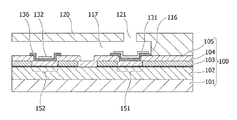
本発明の一実施形態に係る液体吐出ヘッドの配線レイアウトを例示する上面図を図2に、図2におけるA−A’線での断面図を図3に、それぞれ示す。液体吐出ヘッド用基板100には、図3に示すように、シリコンなどの基板101上にSiO2,SiNなどの絶縁材料からなる蓄熱層102介して、発熱抵抗体層103が設けられている。発熱抵抗体層103は、TaSiN等の公知の材料で構成される。発熱抵抗体層103上にはAl,Al−Si,Al−Cu等の金属材料からなる配線としての配線層104が設けられる。配線層104の一部を除去したギャップ間に露出した発熱抵抗体層103部分が第一の電気熱変換部151及び第二の電気熱変換部152となる。配線層104上にはSiO2,SiNなどの絶縁材料からなり、第一及び第二の電気熱変換部と液室内の液体の接触を遮断する絶縁性の保護層105が設けられ、保護層105上に密着配線層116が設けられる。保護層105を含む第一の電気熱変換部151の周辺を発熱部と称することがある。密着配線層116の一部は、保護層105に設けたスルーホール110を介して、第一及び第二の電気熱変換部151、152とは電気的に分離された配線層104に接続される(図示せず)。一方、保護層105上には、密着配線層136を介して、対向電極132が設けられている。密着配線層136は、保護層105に設けたスルーホール111を介して、第一及び第二の電気熱変換部151、152とは電気的に分離された配線層104に接続される(図示せず)。上部電極131及び対向電極132と電気的に接続された配線層104は、図1に示す配線経路135の一部となる。配線層104は、基板端部に設けた端子部(不図示)を介して、後述する記録装置内に設けた外部回路に接続される。本実施形態では、電気的に分離された配線が複数存在する。例えば、一方は保護層下に設けた発熱抵抗体層103と配線層104の積層からなる配線のうち、配線層104にギャップを設けて第一の電気熱変換部151となる配線である。また、他方は配線層104にギャップを設けて第二の電気熱変換部152となる配線であり且つ配線経路145の一部となる配線と、配線経路135の一部となる配線である。
A top view illustrating the wiring layout of the liquid discharge head according to an embodiment of the present invention is shown in FIG. 2, and a cross-sectional view taken along the line AA 'in FIG. 2 is shown in FIG. In the liquid
密着配線層116及び136は、上部電極131、対向電極132と保護層105との密着性を向上させる層であり、また、導電性材料を用いることで、配線経路135の一部ともなる。また、第一の電気熱変換部151で発生した熱を液体と接する熱作用部108に熱損失なく伝達する良好な熱伝導性を示す材料であることが好ましい。密着配線層116及び136は、これらの特性を満たす限りはいずれの材料も用いることができるが、部分的に液室内の液体と接触する場合には、耐液性を有する材料であることが好ましい。また密着配線層116は、クリーニング時に上部電極131の電気化学反応による溶出を行う電圧で、上部電極131よりも溶出しにくい材料であり、表面に不働態膜を形成するタンタル(Ta)やニオブ(Nb)などバルブメタルが好ましく使用できる。密着配線層136も同様のバルブメタルを好ましく使用できる。同じ材料を使用することで、密着配線層116及び136を同時に形成することができる。本発明においては、密着配線層136が対向電極配線となる。また、密着配線層116を上部電極配線ということがある。特に、対向電極配線となる密着配線層136がTaまたはNbを含む材料で形成されていると、不働態膜である酸化皮膜が水素により還元されて配線保護機能が低下し、水素脆化を受けやすくなる。このため、これら材料を使用する対向電極配線では、本発明に係る対向電極配線加熱手段140での加熱処理がより有効である。
The adhesion wiring layers 116 and 136 are layers for improving the adhesion between the
上部電極131は、電気化学反応によって液体中に溶出してコゲ除去するという本来的な機能のほかに、第一の電気熱変換部151を物理的・化学的衝撃からの保護する上部保護層としての機能を有する。また、第一の電気熱変換部151で発生した熱を液体に伝達する熱作用部108として良好な熱伝導性を示すことが要求される。電気化学反応による金属の溶出の有無は、一般に種々の金属の電位−pH図を見れば把握することが可能である。上部電極131の材料としては、好ましい溶出領域をもち、かつ700℃程度の加熱により強固な酸化膜を形成しない材料が好ましく使用できる。このような材料として、IrまたはRuの単体、あるいはIrと他の金属との合金もしくはRuと他の金属との合金を選定することが好ましい。特に、コゲ除去としての機能は、IrまたはRuの含有率が多いほど電気化学反応が効率良く進行するので、それぞれの金属単体の場合が最も好ましいものである。しかしながら、Ir合金もしくはRu合金の場合であっても、本発明の効果を得ることができるものである。このように、少なくとも、IrまたはRuを含む材料であれば本発明の効果を得られるものである。
The
対向電極132は、上部電極131と同様に液室内の液体に接することから、液体に接しても電気的に安定な材料であれば、いずれの材料も使用できる。例えば、上部電極131と同じ金属材料を用いることができる。上部電極131と同じ金属材料を用いると、上部電極131と同時に、対向電極132を形成することができる。
Since the
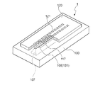
図4は、本発明の一実施形態例になる液体吐出ヘッド1の部分破断斜視図を示す。この液体吐出ヘッド1は、所定のピッチで熱作用部108(上部電極131)が形成された素子列を、基板100を貫通する液体供給路107を挟んで2列並列させてなる液体吐出ヘッド用基板100を有している。この液体吐出ヘッド1は、図2に示すような配線レイアウトを採用することができる。本発明の液体吐出ヘッドは、図4に示す例に限定されず、多色に対応したヘッド、例えば、各色に対応した吐出口列を並列に配置したものや、各色に対応した吐出口列を直列に配置したものであってもよい。
FIG. 4 shows a partially broken perspective view of the
(2.クリーニング動作(コゲ除去動作)の説明)
本発明のコゲ除去動作は、上部電極131をアノード電極、対向電極132をカソード電極とし、電解液である液体(インク)との電気化学反応を利用する。アノード電極である上部電極131を溶出させることで、堆積したコゲを上部電極131の溶出と共に除去することができる。なお、コゲ除去動作時に、特許文献1に開示されているように、上部電極131と対向電極132の極性を反転させると、コゲ除去動作時に電極表面に吸着ないしは引き寄せられた液体中の成分を液体中に再放出することが可能となる。極性を反転させると上部電極131上で水素が発生し、その周辺の上部電極配線(密着配線層116)が水素に曝されるが、第一の電気熱変換部151を駆動する液体吐出の際に加熱されるため、上部電極配線の水素脆化の影響は殆どない。もちろん、クリーニング動作中に第一の電気熱変換部151を駆動して、上部電極配線から積極的に水素を追い出す様にしてもよい。
(2. Description of the cleaning operation (Koge removal operation))
The kogation removing operation of the present invention uses the
(3.記録装置の説明)
図5は本実施形態に係る記録装置500の概略構成例を示すものである。
図示の記録装置500において、キャリッジ505は無端ベルト501に固定され、かつガイドシャフト502に沿って移動可能になっている。無端ベルト501はプーリ503A,503Bに巻回され、一方のプーリ503Aにはキャリッジ駆動モータ504の駆動軸が連結されている。従って、キャリッジ505は、モータ504の回転駆動に伴いガイドシャフト502に沿って往復方向(A方向)に主走査される。
(3. Description of the recording device)
FIG. 5 shows a schematic configuration example of the
In the illustrated
キャリッジ505上には、カートリッジ形態のヘッドユニット410が搭載されている。ここで、ヘッドユニット410は、液体吐出ヘッド1の吐出口121が記録媒体としての用紙Pと対向し、かつ吐出口121の配列方向が主走査方向(A方向)と異なる方向(例えば用紙Pの搬送方向である副走査方向(B方向))に一致するようにキャリッジ505に搭載される。なお、ヘッドユニット410は、例えば、図6に示す構成例を有することができる。図6中、402は液体吐出ヘッド1に電力を供給するための端子を有するTAB(Tape Automated Bonding)用のテープ部材である。このテープ部材402は、記録装置本体から接点403を介して電力や各種信号をやり取りすることができる。404は液体(インク)を液体吐出ヘッド1に供給するためのタンクである。すなわち、図6のヘッドユニット410は、図5の記録装置500に装着可能なカートリッジの形態を有するものである。また、ヘッドユニット410は、液体吐出ヘッド1とタンク404とが別体となったタンク分離型であってもよい。また、液体吐出ヘッド1が複数色に対応したものであってもよい。タンク404は、キャリッジ505以外に配置し、チューブ等によりキャリッジ505に搭載の液体吐出ヘッド1に供給してもよい。液体吐出ヘッド1及びタンク404の組は、使用するインク色に対応した個数を設けることができ、図5に図示の例では4色(例えばブラック、イエロー、マゼンタ、シアン)に対応して4組設けられている。
On the
また、図5の記録装置500には、キャリッジ505の主走査方向上の移動位置を検出するなどの目的でリニアエンコーダ506が設けられている。リニアエンコーダ506の一方の構成要素としてはキャリッジ505の移動方向に沿って設けられたリニアスケール507があり、このリニアスケール507には所定密度で、等間隔にスリットが形成されている。一方、キャリッジ505には、リニアエンコーダ506の他方の構成要素として、例えば、発光部及び受光センサを有するスリットの検出系508及び信号処理回路が設けられている。従って、リニアエンコーダ506からは、キャリッジ505の移動に伴って、インク吐出タイミングを規定するための吐出タイミング信号及びキャリッジの位置情報が出力される。
Further, in the
記録媒体としての記録紙Pは、キャリッジ505のスキャン方向と直交する矢印B方向に間欠的に搬送される。記録紙Pは搬送方向上流側の一対のローラユニット509及び510と、下流側一対のローラユニット511及び512とにより支持され、一定の張力を付与されて液体吐出ヘッド1に対する平坦性を確保した状態で搬送される。各ローラユニットに対する駆動力は、ここでは図示しない搬送モータから伝達される。
The recording paper P as a recording medium is intermittently transported in the arrow B direction orthogonal to the scanning direction of the
以上のような構成によって、キャリッジ505の移動に伴い液体吐出ヘッド1の吐出口121の配列幅に対応した幅の記録と用紙Pの搬送とを交互に繰り返しながら、用紙P全体に対する記録が行われる。
With the above-described configuration, the recording on the entire sheet P is performed while alternately repeating the recording of the width corresponding to the arrangement width of the
なお、キャリッジ505は、記録開始時または記録中に必要に応じてホームポジションで停止する。このホームポジションには、各液体吐出ヘッド1の吐出口121が設けられた面(吐出口面)をキャッピングするキャップ部材513が設けられている。このキャップ部材513には、キャップ内に負圧を発生させ、吐出口121からインクを吸引して強制的に液室内の液体を排出させる機構(不図示)が接続されている。このような液体を吸引、排出させる機構は、一般に、吸引回復機構と呼ばれ、これによって行われる液体排出動作は吸引回復動作と呼ばれている。この吸引回復動作によって、吐出口121の目詰まり等が防止される。
The
図7は上記構成の記録装置500における制御系の構成例を示すブロック図である。
図7において、1700はインタフェースであり、コンピュータ,デジタルカメラ,スキャナ等適宜の形態を有するホスト装置1000から送られてくるコマンドや画像データを含む記録信号を受信する。また、ホスト装置1000に対しては必要に応じ記録装置のステータス情報を送出する。制御部90内には、MPU1701、ROM1702、DRAM1703、ゲートアレイ(G.A.)1704、エネルギーテーブル1725、EEPROM等の不揮発性メモリ1726が含まれる。MPU1701は、ROM1702に記憶された図8について後述するクリーニング処理及びエネルギー設定処理手順に対応した制御プログラムや所要のデータに従って記録装置500内の各部を制御する。ROM1702に記憶されるデータとしては、例えば以下のものが挙げられる。
・第一の電気熱変換部151に印加する駆動パルスの形状や印加時間などの液体吐出ヘッド1の定常的な駆動条件
・上部電極131と対向電極132との間に印加する電圧
・加熱手段140において第二の電気熱変換部152に印加する電圧や駆動パルスの形状や印加時間など。
また、記録媒体搬送の条件、さらにはキャリッジ速度等も含めることができる。
FIG. 7 is a block diagram showing a configuration example of a control system in the
In FIG. 7,
· Steady driving conditions of the
In addition, conditions of recording medium conveyance, and also carriage speed etc. can be included.
DRAM1703は各種データ(上記記録信号やヘッドに供給される記録データ等)を保存しておく。また、DRAM1703には後述する制御の過程で使用されるフラグ用の領域等を設けておくことができる。ゲートアレイ1704は、液体吐出ヘッド1に対する記録データの供給制御を行い、インタフェース1700、MPU1701及びDRAM1703間のデータ転送制御も行う。エネルギーテーブル1725は、インク吐出に必要なエネルギーを決定するデータ、例えば吐出信号のパルス幅を格納する。不揮発性メモリ1726には所要のデータを記録装置の電源オフ時にも保存しておく。また、エネルギーテーブル1725には、第二の電気熱変換部152に印加するエネルギーを決定するデータを格納することができる。
The
504は図5に示すキャリッジ駆動モータ504である。1709は搬送モータであり、記録紙Pを搬送するための駆動源として用いられる。1711は回復系モータであり、図5に示すキャップ部材513のキャッピング動作や、吸引回復を行うポンプ等の吸引回復手段の動作における駆動源として用いられる。1706、1707、1708は、それぞれ、キャリッジ駆動モータ504、搬送モータ1709及び回復系モータ1711を駆動するためのモータドライバである。1705は液体吐出ヘッド1の駆動や、クリーニング動作及び吐出エネルギー設定動作を行うためのヘッドドライバである。図7では加熱手段140を示しているが、加熱手段140はヘッドドライバ1705に組み込むことができる。
(4.クリーニングシーケンスの説明)
図8は本発明の液体吐出ヘッド1を用いる記録装置500が実施可能なクリーニング処理手順の一例を示す。
(4. Description of cleaning sequence)
FIG. 8 shows an example of the cleaning process that can be performed by the
ホスト装置1000等から記録指示が行われると本手順が開始され、まずホスト装置1000から記録に係る画像データを受信し、これを記録装置に適合するデータとして展開する(ステップS1)。そして当該展開した記録データに基づき、記録用紙Pの搬送とキャリッジ505の主走査とを交互に行いながら、液体吐出ヘッド1による記録動作を実行する(ステップS2)。また、この際、記録ドット数(第一の電気熱変換部151の駆動パルス数)のカウントを実施する。
When a recording instruction is issued from the
そして1単位(例えば記録用紙1枚分)の記録動作が終了すると、不揮発性メモリ1726に格納されているドットカウント値の累積データを読み出し(ステップS3)、これに今回カウントしたドット数を加算する(ステップS4)。次に、当該加算値が所定の値Th(例えば1×10⁷)以上となった(Yes)か否(No)かを判定する(ステップS5)。
ここで肯定判定(Yes)であれば、クリーニング動作を開始する。
When the recording operation of one unit (for example, one sheet of recording paper) is completed, the accumulated data of the dot count value stored in the
If the determination result is affirmative (Yes), the cleaning operation is started.
以下、本発明における第一の実施形態について、図8を用いて説明する。第一の実施形態はクリーニング動作中に対向電極周辺の液室内に位置する対向電極配線を加熱する工程を含む。
図1に示す加熱手段140において、第二の電気熱変換部152(対向電極配線用ヒータともいう)の駆動を開始する(ステップS11)。図1に示すクリーニング手段130において、上部電極131がアノード側、対向電極132がカソード側となるように電圧を印加し、クリーニング動作を実施する(ステップS12)。クリーニング完了後(ステップS13)、対向電極配線用ヒータの駆動を停止する(ステップS14)。
Hereinafter, the first embodiment of the present invention will be described with reference to FIG. The first embodiment includes the step of heating the counter electrode wiring located in the liquid chamber around the counter electrode during the cleaning operation.
In the heating means 140 shown in FIG. 1, the driving of the second electrothermal converter 152 (also referred to as a counter electrode wiring heater) is started (step S11). In the cleaning means 130 shown in FIG. 1, a voltage is applied so that the
対向電極配線用ヒータは、常時数百℃を維持するよりも、パルス電圧で駆動するほうがインクの変質を引き起こさないため好ましい。また、対向電極配線下のヒータにより、インクが発泡するエネルギーの閾値をEthとし、そのときの熱貫流率k値を1とする。本発明では、対向電極配線用ヒータの駆動条件は、k値が1以上(液体が発泡する値以上)であっても、1未満(液体が発泡する値未満)であっても、構わない。 The heater for counter electrode wiring is preferably driven by a pulse voltage because it does not cause deterioration of the ink, rather than always maintaining several hundred degrees Celsius. Further, the threshold value of the energy for bubbling the ink is set to Eth by the heater under the counter electrode wiring, and the heat transmission coefficient k value at that time is set to 1. In the present invention, the drive condition of the counter electrode wiring heater may be k value of 1 or more (more than the value at which the liquid foams) or less than 1 (less than the value of the liquid foam).
クリーニング動作では、熱作用部108上のコゲが上部電極131の表面の電気化学反応による溶出とともに除去される。係るクリーニング動作を行った後には、吐出口121付近には溶出した上部電極131の形成材料と剥離したコゲとを含む液体(インク)が滞留している。記録品位に影響を及ぼすものでなければ、このインクをそのまま次回の記録動作に用いることで吐出口121から吐出させてしまうこともできる。しかし本実施形態では、吸引回復等を実施することで(ステップS15)、そのインクを積極的に排出するようにする。
In the cleaning operation, the kogation on the
クリーニング動作では、熱作用部108上のコゲが上部電極131の表面の電気化学反応による溶出とともに除去される。クリーニング動作に伴って、上部電極131の表面が溶出するため、熱作用部108における上部電極131の膜厚が減少する。このため、高い記録品位を保つためには、発泡に必要なパルス幅の閾値であるPthを再度測定し、これを記憶更新する(ステップS41、S42)。その後、不揮発性メモリ1726に格納されているドットカウント値の累積データをクリア(リセット)し(ステップS43)、一連の記録処理を終了する。
In the cleaning operation, the kogation on the
一方、ステップS5にて否定判定(No)された場合には、上記加算値をもって不揮発性メモリ1726に格納されているドットカウント値の累積データを更新し(ステップS44)、記録処理を終了する。
On the other hand, when a negative determination (No) is made in step S5, the accumulated data of the dot count value stored in the
なお、以上の手順では記録動作後にコゲ除去処理ないし回復処理を実施するものとしたが、記録動作に先立って行うようにしてもよい。この場合には、ステップS1で展開した記録データに基づいてドットカウントを行い、これをドットカウントの累積値に加算し、その加算値に基づいてコゲ除去処理の実施の有無を判定するようにすることができる。また、所定量の記録動作毎(例えば液体吐出ヘッドの1または数スキャン毎)にコゲ除去処理が実施されるようにすることも可能である。 In the above procedure, the kogation removing process or the recovery process is performed after the recording operation, but may be performed prior to the recording operation. In this case, dot count is performed based on the print data expanded in step S1, and this is added to the dot count accumulation value, and it is determined whether or not the kogation removal processing is to be performed based on the addition value. be able to. Further, it is also possible to execute the kogation removing process every predetermined amount of recording operation (e.g., every one or several scans of the liquid discharge head).
また、コゲ除去処理後に液体を排出させるための処理としては、上述したような吸引回復に限られない。吐出口に至るインク供給系を加圧することで排出を行わせるものでもよい。また、記録動作とは別に第一の電気熱変換部151を駆動してインクを吐出させる処理(予備吐出処理)により排出を行うものでもよい。この場合には、予備吐出のための駆動パルスも上記カウントに反映させることができる。
Further, the treatment for discharging the liquid after the kogation removing treatment is not limited to the suction recovery as described above. The ink may be discharged by pressurizing the ink supply system leading to the discharge port. Alternatively, discharge may be performed by processing (preliminary discharge processing) in which the first
このように、本実施形態のクリーニング方法では、クリーニング動作を行っている間は、対向電極配線用ヒータが駆動されているため、対向電極にて発生した水素の対向電極配線内への吸蔵は抑制される。そのため、クリーニングを繰り返し行っても、対向電極配線の割れが発生することなく、長期間にわたり安定性に優れたクリーニング処理を実施することが可能となる。 As described above, in the cleaning method of the present embodiment, the heater for the counter electrode wiring is driven while the cleaning operation is performed, so that the storage of hydrogen generated in the counter electrode into the counter electrode wiring is suppressed. Be done. Therefore, even if the cleaning is repeated, it is possible to carry out a cleaning process with excellent stability over a long period of time without the occurrence of cracking of the counter electrode wiring.
次に、本発明における第二の実施形態について、図9を用いて説明する。第二の実施形態はクリーニング動作後に対向電極周辺の液室内に位置する対向電極配線を加熱する工程を含む。
ドットカウントの加算値を判定するステップS5までは、第一の実施形態と同じであり、ここで肯定判定(Yes)であれば、クリーニング動作を開始する。(ステップS21)。その後、所定の時間経過後、クリーニング動作を停止し(ステップS22)、吸引回復を行う(ステップS23)。その後、液室内のインクを排出する(ステップS24)。液体を排出させるための処理としては、吸引回復であっても、吐出口に至るインク供給系を加圧することで排出を行わせるものでもよい。液室内のインクを十分排出した後、対向電極配線用ヒータを駆動して加熱を開始する(ステップS25)。このとき、液室内のインクは排出されているため、インクの変質を考慮することなく、駆動条件を設定して構わないので、直流であってもパルスであってもよい。
Next, a second embodiment of the present invention will be described with reference to FIG. The second embodiment includes the step of heating the counter electrode wiring located in the liquid chamber around the counter electrode after the cleaning operation.
The process up to step S5 for determining the added value of the dot count is the same as in the first embodiment, and if the determination is affirmative (Yes), the cleaning operation is started. (Step S21). Thereafter, after a predetermined time has elapsed, the cleaning operation is stopped (step S22), and suction recovery is performed (step S23). Thereafter, the ink in the liquid chamber is discharged (step S24). As a process for discharging the liquid, even in the suction recovery, the discharge may be performed by pressurizing the ink supply system leading to the discharge port. After the ink in the liquid chamber is sufficiently discharged, the counter electrode wiring heater is driven to start heating (step S25). At this time, since the ink in the liquid chamber is discharged, the drive condition may be set without considering the deterioration of the ink, and therefore, it may be a direct current or a pulse.
その後、ヒータ駆動を停止して加熱を停止し(ステップS26)、インクを充填する(ステップS27)。以降の工程は、第一の実施形態と同様である。
このように、本実施形態のクリーニング方法では、クリーニング動作中に対向電極配線が吸蔵した水素を、インク排出後に対向電極配線用ヒータを駆動することにより追いだすことができる。液室内にインクがないため、より効果的な駆動条件を設定することができる。
Thereafter, the heater drive is stopped to stop the heating (step S26), and the ink is filled (step S27). The subsequent steps are the same as in the first embodiment.
As described above, in the cleaning method of the present embodiment, the hydrogen absorbed by the counter electrode wiring during the cleaning operation can be removed by driving the heater for the counter electrode wiring after the ink is discharged. Since there is no ink in the liquid chamber, more effective drive conditions can be set.
続いて、本発明における第三の実施形態について、図10を用いて説明する。第三の実施形態はクリーニング動作中に対向電極周辺の液室内に位置する対向電極配線を加熱する工程を含む。また、当該加熱工程は液室内の液体を置換しながら行う。
ドットカウントの加算値を判定するステップS5までは、第一の実施形態と同じであり、ここで肯定判定(Yes)であれば、吸引回復を開始する(ステップS31)。その後、対向電極配線用ヒータ駆動を開始し(ステップS32)、クリーニング動作を開始する(ステップS33)。所定の時間経過後、クリーニング動作を停止し(ステップS34)、対向電極配線用ヒータ駆動を停止(ステップS35)、吸引回復動作を停止する(ステップS36)。以降の工程は、第一の実施形態と同様である。
Subsequently, a third embodiment of the present invention will be described with reference to FIG. The third embodiment includes the step of heating the counter electrode wiring located in the liquid chamber around the counter electrode during the cleaning operation. The heating process is performed while replacing the liquid in the liquid chamber.
The process up to step S5 for determining the added value of the dot count is the same as in the first embodiment, and if the determination result is affirmative (Yes), suction recovery is started (step S31). Thereafter, the driving of the counter electrode wiring heater is started (step S32), and the cleaning operation is started (step S33). After a predetermined time has elapsed, the cleaning operation is stopped (step S34), the driving of the counter electrode wiring heater is stopped (step S35), and the suction recovery operation is stopped (step S36). The subsequent steps are the same as in the first embodiment.
このように、本実施形態のクリーニング方法では、対向電極配線ヒータ駆動を吸引回復中(液体を置換させる置換動作中)に行うため、変質したインクは廃棄される。そのため、印字への影響を気にすることなく、対向電極配線用ヒータを駆動することができ、より効果的に対向電極配線内の水素を追いだすことができる。 As described above, in the cleaning method of the present embodiment, since the counter electrode wiring heater is driven during suction recovery (during replacement operation for replacing liquid), the degraded ink is discarded. Therefore, the heater for opposing electrode wiring can be driven without worrying about the influence on printing, and hydrogen in the opposing electrode wiring can be more effectively expelled.
以下、実施例を挙げて本発明の実施の形態を具体的に説明するが、本発明はこれらの実施例のみに限定されるものでは無い。 EXAMPLES Hereinafter, the embodiments of the present invention will be specifically described by way of examples, but the present invention is not limited to these examples.
(実施例1)
<液体吐出ヘッドの製造>
本実施例の液体吐出ヘッドとして、特許文献1に開示の方法と同様にして図2(又は図3)となるように、Siで形成された基板101上にSiO2蓄熱層、TaSiN発熱抵抗体層103、Al配線層104、SiN保護層105を順次形成した。なお、第一及び第二の電気熱変換部151,152はAl配線層104の一部をエッチング除去して形成した。その後、保護層105上に、密着配線層116、136としてタンタルを100nm形成した後、イリジウム膜を50nm成膜した。イリジウム膜をパターニングし、上部電極131、対向電極132をそれぞれ形成した。その後は、特許文献1と同様に、インク供給路107の形成、流路形成部材120の形成、その他必要な端子部の形成等を経て液体吐出ヘッドを完成した。なお、本実施例では、図6に示したようなインクタンク一体型のヘッドユニットではなく、インクタンク分離型とした。
Example 1
<Manufacture of liquid discharge head>
As a liquid discharge head of this embodiment, a SiO 2 heat storage layer, a TaSiN heating resistor, and the like are formed on a
<コゲ除去実験>
第一の実施形態について、図8のクリーニング動作手順に従って、上記の液体吐出ヘッドを用いたコゲ除去実験を実施した。
インクは染料マゼンダインクを用いた。実験方法は、まず、新規のインクタンクを液体吐出ヘッドにセットし、熱作用部108上にコゲが堆積するように所定条件で第一の電気熱変換部151を駆動してコゲ付けをした。表面状態を観察すると、熱作用部108には、ほぼ均一にコゲKと呼ばれる不純物が堆積していた。この状態の液体吐出ヘッドを用いた記録を行うと、コゲKの堆積により記録品位が低下していることが確認された。対向電極用ヒータ(第二の電気熱変換部152)の駆動条件を、インクが発泡するエネルギー閾値をk値1.0とした場合、k値0.8となるように設定し、パルス電圧を印加し、クリーニングを行った。クリーニング終了後、パルス電圧を停止し、吸引回復後、印字品位を確認した。
<Skage removal experiment>
In the first embodiment, the kogation removing experiment using the liquid ejection head described above was performed according to the cleaning operation procedure of FIG.
The ink used dye magenta ink. In the experimental method, first, a new ink tank was set in the liquid discharge head, and the first
この一連の流れ、「新規インクタンクセット、コゲ付け駆動、対向電極配線ヒータ駆動、クリーニング動作、印字品位確認」、を1シーケンスとし、このシーケンスを5サイクル行った。なお、コゲ取り条件は、10V40秒とした。
それぞれのサイクルにおいてシーケンス終了後の熱作用部108の表面状態を観察すると、それまで堆積していたコゲKが除去されていることが確認され、対向電極配線割れも発生していなかった。インクタンク交換後に記録を行うと、記録品位は初期とほぼ同等に回復していた。
This series of flow, “new ink tank set, drive with charge, drive for opposite electrode wiring heater, cleaning operation, print quality check” was made one sequence, and this sequence was performed 5 cycles. The kogation removal condition was 10 V 40 seconds.
Observation of the surface condition of the
(実施例2)
実施例1における、対向電極ヒータ駆動条件を、k値1.2となるように設定した以外は、実施例1と同じ実験を行った。5サイクルのシーケンス終了後、表面状態を観察すると、コゲKが除去できていること、対向電極配線割れも起きてないことを確認した。
(Example 2)
The same experiment as that of Example 1 was performed except that the counter electrode heater driving condition in Example 1 was set to a k value of 1.2. After completion of the five-cycle sequence, the surface condition was observed to confirm that kogation K could be removed and that no cracking of the counter electrode wiring had occurred.
(比較例1)
対向電極配線用ヒータの駆動を行わなかった以外は、実施例1と同じ条件で、コゲ除去実験を行った。5サイクルのシーケンス終了後、コゲKの除去残りと、対向電極配線割れが観察された。
(Comparative example 1)
The kogation removing experiment was performed under the same conditions as in Example 1 except that the driving of the counter electrode wiring heater was not performed. After completion of the 5 cycle sequence, the removal of koge K and the counter electrode wiring crack were observed.
(実施例3)
本発明の第二の実施形態ついて、図9のクリーニング動作手順に従って、実施例1で作製した液体吐出ヘッドを用いたコゲ除去実験を実施した。
インクは染料マゼンダインクを用いた。実験方法は、まず、新規のインクタンクを液体吐出ヘッドにセットし、熱作用部108上にコゲが堆積するように所定条件で電気熱変換部151を駆動してコゲ付けをした。表面状態を観察すると、熱作用部108には、ほぼ均一にコゲKと呼ばれる不純物が堆積していた。この状態の液体吐出ヘッドを用いた記録を行うと、コゲKの堆積により記録品位が低下していることが確認された。その後、10V40秒のクリーニングを行った。吐出口からの吸引により、液室内のインクを排出した(S24)。その後、対向電極用ヒータに、温度が200℃となるように直流電圧を印加した。
(Example 3)
With respect to the second embodiment of the present invention, in accordance with the cleaning operation procedure of FIG. 9, a kogation removing experiment using the liquid discharge head manufactured in Example 1 was carried out.
The ink used dye magenta ink. In the experimental method, first, a new ink tank was set in the liquid discharge head, and the
この一連の流れ、「新規インクタンクセット、コゲ付け駆動、クリーニング動作、対向電極配線ヒータ駆動、印字品位確認」、を1シーケンスとし、このシーケンスを5サイクル行った。
それぞれのサイクルにおいてシーケンス終了後の熱作用部108の表面状態を観察すると、それまで堆積していたコゲKが除去されていることが確認され、対向電極配線割れも発生していなかった。インクタンク交換後に記録を行うと、記録品位は初期とほぼ同等に回復していた。
A series of this flow, “new ink tank set, drive with charging, cleaning operation, counter electrode wiring heater drive, print quality check” was made one sequence, and this sequence was performed five cycles.
Observation of the surface condition of the
(実施例4)
本発明の第三の実施形態ついて、図10のクリーニング動作手順に従って、実施例1で作製した液体吐出ヘッドを用いたコゲ除去実験を実施した。
インクは染料マゼンダインクを用いた。実験方法は、まず、新規のインクタンクを液体吐出ヘッドにセットし、熱作用部108上にコゲが堆積するように所定条件で電気熱変換部151を駆動してコゲ付けをした。表面状態を観察すると、熱作用部108には、ほぼ均一にコゲKと呼ばれる不純物が堆積していた。この状態の液体吐出ヘッドを用いた記録を行うと、コゲKの堆積により記録品位が低下していることが確認された。その後、インクタンクのセット、吸引回復、対向用ヒータ駆動、クリーニング動作を行った。
対向電極用ヒータ駆動条件は、k値1.3のパルス電圧とした。クリーニング終了後、パルス電圧を停止し、吸引回復停止後、印字品位を確認した。
(Example 4)
With respect to the third embodiment of the present invention, in accordance with the cleaning operation procedure of FIG. 10, a kogation removing experiment using the liquid discharge head manufactured in Example 1 was performed.
The ink used dye magenta ink. In the experimental method, first, a new ink tank was set in the liquid discharge head, and the
The heater drive condition for the counter electrode was a pulse voltage with a k value of 1.3. After completion of the cleaning, the pulse voltage was stopped, and after stopping the suction recovery, the print quality was confirmed.
この一連の流れ、「新規インクタンクセット、コゲ付け駆動、吸引動作、対向電極配線ヒータ駆動、クリーニング動作、印字品位確認」、を1シーケンスとし、このシーケンスを5サイクル行った。なお、コゲ取り条件は、10V40秒とした。
それぞれのサイクルにおいてシーケンス終了後の熱作用部108の表面状態を観察すると、それまで堆積していたコゲKが除去されていることが確認され、対向電極配線割れも発生していなかった。インクタンク交換後に記録を行うと、記録品位は初期とほぼ同等に回復していた。
A series of this flow, “new ink tank set, drive with charging, suction operation, counter electrode wiring heater drive, cleaning operation, print quality check” was regarded as one sequence, and five cycles of this sequence were performed. The kogation removal condition was 10 V 40 seconds.
Observation of the surface condition of the
以上の実施例では、通常、10Vで10〜30秒のコゲ取り条件を、40秒に時間を延ばした条件で実施した例を示した。本発明によると、電圧を高めて水素の発生スピードが速いクリーニング条件や、通常の電圧でクリーニング回数が増加する場合においても水素脆化が発生するが、このような場合であっても対向電極配線の割れを防ぐことが可能となる。これらの対策では、記録装置の停止時間を短縮することができる。本発明においては、このような水素脆化による対向電極配線の割れを防ぎ、クリーニング動作を所定の回数まで確実に行うことができる。また、十分なコゲ除去により液体吐出ヘッドの吐出特性を安定させ、信頼性のある高品位の画像記録を行うことが可能となる。したがって、本発明の産業上の利用可能性は極めて高い。 In the above-mentioned example, the example which carried out the conditions of 10 to 30 seconds of kogee removal of 10 V normally was implemented on the conditions which extended time to 40 seconds. According to the present invention, hydrogen embrittlement occurs even under cleaning conditions where the voltage is increased and the hydrogen generation speed is high, or when the number of times of cleaning is increased with a normal voltage, but even in such a case, the counter electrode wiring Can be prevented. With these measures, the stop time of the recording apparatus can be shortened. In the present invention, such cracking of the counter electrode wiring due to hydrogen embrittlement can be prevented, and the cleaning operation can be reliably performed up to a predetermined number of times. In addition, the discharge characteristics of the liquid discharge head can be stabilized by the sufficient removal of the kogation, and reliable high-quality image recording can be performed. Therefore, the industrial applicability of the present invention is extremely high.
以上の説明では、液体として吐出用の液体(インク)を用いる場合を説明したが、本発明はこれに限定されず、液体吐出ヘッドのリサイクル時の洗浄液などについても、対向電極付近でクリーニング(コゲ取り)時に水素発生を伴う場合に適用することができる。 In the above description, although the case of using the discharge liquid (ink) as the liquid has been described, the present invention is not limited to this, and cleaning of the liquid discharge head, etc. is also performed near the counter electrode Can be applied to cases involving hydrogen evolution at times.
1 液体吐出ヘッド
100 液体吐出ヘッド用基板
101 Si基板
102 蓄熱層
103 発熱抵抗体層
104 配線層
105 保護層
107 液体供給路
108 熱作用部
116 密着配線層
117 液室
120 流路形成部材
121 液体吐出口
130 クリーニング手段
131 上部電極
132 対向電極
133 電源
134 スイッチ
135 配線経路
136 密着配線層(対向電極配線)
140 加熱手段
143 電源
144 スイッチ
145 配線経路
151 第一の電気熱変換部
152 第二の電気熱変換部
140 heating means 143
Claims (15)
前記液体吐出口に連通する液室と、
前記液室に配置された第一の電気熱変換部と、
前記第一の電気熱変換部と前記液室内の液体との接触を遮断する絶縁性の保護層と、
前記保護層の前記第一の電気熱変換部によって加熱される発熱部を少なくとも覆い、前記液体との電気化学反応によって溶出する金属を含む材料で構成された第一の電極と、
前記液体を介して前記第一の電極と電気的に接続可能に設けられ、前記第一の電極と前記液体との前記電気化学反応を生起するための第二の電極と、
前記第二の電極に接続された電極配線と、
を備えた液体吐出ヘッドであって、
前記第二の電極周辺の前記液室内に位置する前記電極配線を加熱する手段を有することを特徴とする液体吐出ヘッド。 A liquid outlet,
A liquid chamber communicating with the liquid discharge port;
A first electrothermal converter disposed in the liquid chamber;
An insulating protective layer which blocks contact between the first electrothermal transducer and the liquid in the liquid chamber;
A first electrode made of a material including at least a heat generating portion heated by the first electrothermal conversion portion of the protective layer and containing a metal eluted by an electrochemical reaction with the liquid;
The provided liquid connectable said first electrode and electrically via a second electrode to raise the electrochemical reaction between the said first electrode liquid,
An electrode wire connected to the second electrode ;
A liquid discharge head provided with
A liquid discharge head comprising means for heating the electrode wiring located in the liquid chamber around the second electrode .
前記クリーニング動作中、または前記クリーニング動作後に前記第二の電極周辺の前記液室内に位置する前記電極配線を加熱する工程を含むことを特徴とする液体吐出ヘッドのクリーニング方法。 A liquid discharge port, a liquid chamber communicating with the liquid discharge port, a first electrothermal converter disposed in the liquid chamber, a contact between the first electrothermal converter and the liquid in the liquid chamber an insulating protective layer for blocking said covering at least a heating portion that is heated by said first electrothermal transducer portion of the protective layer, the formed of a material containing a metal elutes by an electrochemical reaction between the liquid and one electrode, through the liquid provided to be connected the first electrode and electrically, a second electrode to raise the electrochemical reaction between the said first electrode liquid, in the liquid discharge head and an electrode wiring connected to the second electrode, a cleaning for removing kogation deposited on the first electrode elution co by electrochemical reactions of the first electrode Operation of the liquid discharge head cleaning method I,
A method of cleaning a liquid discharge head, comprising the step of heating the electrode wiring located in the liquid chamber around the second electrode during the cleaning operation or after the cleaning operation.
前記第一の電極と前記第二の電極との間に電圧を印加することにより、前記第一の電極の上に堆積するコゲを、前記第一の電極の溶出と共に除去する処理を行うクリーニング手段と、
前記第二の電極周辺の前記液室内に位置する前記電極配線を加熱する手段と、
を有することを特徴とする記録装置。 A liquid discharge port, a liquid chamber communicating with the liquid discharge port, a first electrothermal converter disposed in the liquid chamber, a contact between the first electrothermal converter and the liquid in the liquid chamber an insulating protective layer for blocking said covering at least a heating portion that is heated by said first electrothermal transducer portion of the protective layer, the formed of a material containing a metal elutes by an electrochemical reaction between the liquid and one electrode, through the liquid provided to be connected the first electrode and electrically, a second electrode to raise the electrochemical reaction between the said first electrode liquid, A recording apparatus that performs recording using a liquid discharge head including an electrode wiring connected to the second electrode ,
By applying a voltage between the second electrode and the first electrode, the kogation to be deposited on the first electrode, a cleaning means for performing a process of removing with elution of the first electrode When,
A means for heating the electrode wire located in the liquid chamber around the second electrode ;
A recording apparatus characterized by having:
Priority Applications (2)
| Application Number | Priority Date | Filing Date | Title |
|---|---|---|---|
| JP2015095647A JP6504905B2 (en) | 2015-05-08 | 2015-05-08 | Liquid discharge head, method of cleaning the head, and recording apparatus |
| US15/134,665 US9682552B2 (en) | 2015-05-08 | 2016-04-21 | Liquid ejection head, method of cleaning the same, and recording apparatus |
Applications Claiming Priority (1)
| Application Number | Priority Date | Filing Date | Title |
|---|---|---|---|
| JP2015095647A JP6504905B2 (en) | 2015-05-08 | 2015-05-08 | Liquid discharge head, method of cleaning the head, and recording apparatus |
Publications (3)
| Publication Number | Publication Date |
|---|---|
| JP2016210085A JP2016210085A (en) | 2016-12-15 |
| JP2016210085A5 JP2016210085A5 (en) | 2018-06-14 |
| JP6504905B2 true JP6504905B2 (en) | 2019-04-24 |
Family
ID=57222279
Family Applications (1)
| Application Number | Title | Priority Date | Filing Date |
|---|---|---|---|
| JP2015095647A Active JP6504905B2 (en) | 2015-05-08 | 2015-05-08 | Liquid discharge head, method of cleaning the head, and recording apparatus |
Country Status (2)
| Country | Link |
|---|---|
| US (1) | US9682552B2 (en) |
| JP (1) | JP6504905B2 (en) |
Families Citing this family (5)
| Publication number | Priority date | Publication date | Assignee | Title |
|---|---|---|---|---|
| JP2018079671A (en) | 2016-11-18 | 2018-05-24 | キヤノン株式会社 | Liquid discharge head, liquid discharge device, and control method |
| JP6878153B2 (en) | 2017-06-02 | 2021-05-26 | キヤノン株式会社 | Liquid discharge head, liquid discharge head cleaning method and liquid discharge device |
| WO2019204358A1 (en) | 2018-04-16 | 2019-10-24 | Columbia Sportswear North America, Inc. | Composite foam for midsole |
| JP7427360B2 (en) | 2018-10-12 | 2024-02-05 | キヤノン株式会社 | Liquid ejection device, ejection control method, and liquid ejection head |
| JP7163134B2 (en) | 2018-10-18 | 2022-10-31 | キヤノン株式会社 | Liquid ejection head, method for manufacturing liquid ejection head, and liquid ejection apparatus |
Family Cites Families (11)
| Publication number | Priority date | Publication date | Assignee | Title |
|---|---|---|---|---|
| US5257042A (en) * | 1991-07-09 | 1993-10-26 | Xerox Corporation | Thermal ink jet transducer protection |
| JP3127647B2 (en) * | 1993-01-07 | 2001-01-29 | 富士ゼロックス株式会社 | Thermal control type ink jet recording element |
| JPH10774A (en) * | 1996-06-14 | 1998-01-06 | Canon Inc | Substrate for ink jet recording head and ink jet recording head equipped therewith |
| CA2311017C (en) | 1999-06-14 | 2004-07-20 | Canon Kabushiki Kaisha | Recording head, substrate for use of recording head, and recording apparatus |
| JP3962719B2 (en) | 2002-12-27 | 2007-08-22 | キヤノン株式会社 | Ink-jet head substrate, ink-jet head using the same, and method for producing the same |
| JP4182035B2 (en) | 2004-08-16 | 2008-11-19 | キヤノン株式会社 | Inkjet head substrate, method for producing the substrate, and inkjet head using the substrate |
| JP4926669B2 (en) | 2005-12-09 | 2012-05-09 | キヤノン株式会社 | Inkjet head cleaning method, inkjet head, and inkjet recording apparatus |
| JP5312202B2 (en) | 2008-06-20 | 2013-10-09 | キヤノン株式会社 | Liquid discharge head and manufacturing method thereof |
| JP6120662B2 (en) * | 2013-04-25 | 2017-04-26 | キヤノン株式会社 | Regeneration method of liquid discharge head |
| JP6296720B2 (en) * | 2013-07-29 | 2018-03-20 | キヤノン株式会社 | Liquid discharge head, substrate for liquid discharge head, and recording apparatus |
| JP6300486B2 (en) | 2013-10-18 | 2018-03-28 | キヤノン株式会社 | Liquid discharge head and liquid discharge apparatus |
-
2015
- 2015-05-08 JP JP2015095647A patent/JP6504905B2/en active Active
-
2016
- 2016-04-21 US US15/134,665 patent/US9682552B2/en active Active
Also Published As
| Publication number | Publication date |
|---|---|
| US9682552B2 (en) | 2017-06-20 |
| US20160325548A1 (en) | 2016-11-10 |
| JP2016210085A (en) | 2016-12-15 |
Similar Documents
| Publication | Publication Date | Title |
|---|---|---|
| JP6504905B2 (en) | Liquid discharge head, method of cleaning the head, and recording apparatus | |
| JP4926669B2 (en) | Inkjet head cleaning method, inkjet head, and inkjet recording apparatus | |
| JP6433153B2 (en) | Liquid ejection head, cleaning method for the head, and recording apparatus including the head | |
| US8191988B2 (en) | Liquid ejection head, liquid-ejection head substrate, liquid ejecting apparatus including liquid ejection head, and method of cleaning liquid ejection head | |
| JP6296720B2 (en) | Liquid discharge head, substrate for liquid discharge head, and recording apparatus | |
| JP5825876B2 (en) | Ink jet recording apparatus and control method thereof | |
| US9868283B2 (en) | Liquid discharge head cleaning method and liquid discharge apparatus | |
| JP4995355B2 (en) | Inkjet head and inkjet recording apparatus | |
| US9302481B2 (en) | Nozzle plate, liquid ejecting head, and liquid ejecting apparatus | |
| JP6327982B2 (en) | Cleaning method for liquid discharge head | |
| US9527281B2 (en) | Liquid ejection head and liquid ejection apparatus | |
| JP6878153B2 (en) | Liquid discharge head, liquid discharge head cleaning method and liquid discharge device | |
| US9630399B2 (en) | Method for cleaning liquid ejection head | |
| JP5915940B2 (en) | Droplet discharge head driving method, droplet discharge head, and image forming apparatus | |
| US8936351B2 (en) | Nozzle plate, liquid ejecting head, and liquid ejecting apparatus | |
| JP2006334889A (en) | Method for manufacturing substrate for inkjet head, substrate for inkjet head, and inkjet head | |
| JP2016032880A (en) | Manufacturing method of liquid discharge device and liquid discharge device | |
| JP5896275B2 (en) | Droplet discharge head and image forming apparatus | |
| JP2023079429A (en) | Liquid discharge device | |
| JP2023108829A (en) | Liquid discharge head, liquid discharge device and cleaning method | |
| JP2022028596A (en) | Liquid ejection head, liquid ejection device and cleaning method | |
| JP2021094834A (en) | Recording device, control method, and program | |
| JP6146177B2 (en) | Droplet discharge head, ink jet recording apparatus, and image forming apparatus | |
| JP2014177058A (en) | Liquid jet apparatus | |
| JP2010214767A (en) | Apparatus and method for manufacturing nozzle plate, liquid jetting head, and image forming apparatus |
Legal Events
| Date | Code | Title | Description |
|---|---|---|---|
| A521 | Written amendment |
Free format text: JAPANESE INTERMEDIATE CODE: A523 Effective date: 20180426 |
|
| A621 | Written request for application examination |
Free format text: JAPANESE INTERMEDIATE CODE: A621 Effective date: 20180426 |
|
| A977 | Report on retrieval |
Free format text: JAPANESE INTERMEDIATE CODE: A971007 Effective date: 20190123 |
|
| TRDD | Decision of grant or rejection written | ||
| A01 | Written decision to grant a patent or to grant a registration (utility model) |
Free format text: JAPANESE INTERMEDIATE CODE: A01 Effective date: 20190226 |
|
| A61 | First payment of annual fees (during grant procedure) |
Free format text: JAPANESE INTERMEDIATE CODE: A61 Effective date: 20190326 |
|
| R151 | Written notification of patent or utility model registration |
Ref document number: 6504905 Country of ref document: JP Free format text: JAPANESE INTERMEDIATE CODE: R151 |