JP6504871B2 - Bath door - Google Patents
Bath door Download PDFInfo
- Publication number
- JP6504871B2 JP6504871B2 JP2015064316A JP2015064316A JP6504871B2 JP 6504871 B2 JP6504871 B2 JP 6504871B2 JP 2015064316 A JP2015064316 A JP 2015064316A JP 2015064316 A JP2015064316 A JP 2015064316A JP 6504871 B2 JP6504871 B2 JP 6504871B2
- Authority
- JP
- Japan
- Prior art keywords
- bathroom
- folding door
- opening
- door
- gap
- Prior art date
- Legal status (The legal status is an assumption and is not a legal conclusion. Google has not performed a legal analysis and makes no representation as to the accuracy of the status listed.)
- Active
Links
Images


Description
本発明は、浴室折戸に関する。 The present invention relates to a bathroom door.
浴室用の戸として折戸が一般に多く用いられている。この折戸を浴室内に折り込んで開放しようとすると、その最初の段階で折戸の扉体で押し込まれた浴室の空気の圧力が上昇し、その圧力が折戸に作用して重く感じることがある。
この問題は、浴室内で押し込まれた空気を脱衣室側に逃がせれば解消する。その簡易な解決策としては、例えば扉体(折戸障子部)にガラリを設けることが考えられる。しかし、扉体にガラリを設けると折戸の意匠が大幅に変更されるため、この解決方法は意匠の変更を嫌う場合には適用できない。
Origami doors are generally used as a door for a bathroom. When this folding door is folded and opened in the bathroom, the pressure of the air of the bathroom pushed by the door of the folding door rises in the first stage, and the pressure may act on the folding door and feel heavy.
This problem is solved if the air pushed in the bathroom can escape to the dressing room side. As a simple solution, for example, it can be considered to provide a glar on the door (or folding door shoji part). However, since the design of the folding door is largely changed if the door is provided with a glarly, this solution method can not be applied when the user dislikes the change of the design.
そこで、本出願人は、折戸の扉体の意匠を変えず、しかも、扉体の開放に際し、浴室内の空気を脱衣室内に逃がすことで折戸を円滑に開放することを目的に、浴室折戸において、浴室と脱衣室間に通気路(換気経路)を設けて空気の流通を図った浴室折戸を提案した(特許文献1参照)。
この浴室用の折戸は、図9に示すように、折り戸上枠141の上部上枠141aと下部上枠141bの間にエアー開放口181を設け、このエアー開放口181に、2枚折戸体101の開閉に連動して開閉するダンパーブレード182を備えたエアー開放機構110を有している。2枚の折戸の扉体の閉塞状態からの開放時に、その開放動作に連動してダンパーブレード182を開き、エアー開放口181を開放して、空気を脱衣室側に逃がすようにしている。
Therefore, in order to open the folding door smoothly by letting the air in the bathroom escape into the undressing room without changing the design of the door of the folding door, the applicant of the present invention does not change the design of the door of the folding door.
As shown in FIG. 9, this bathroom folding door has an air opening 181 between the upper
ただ、この浴室折戸では、折戸の開放時に浴室内の空気を脱衣室内に逃がすための通気路は上枠に設けたエアー開放口181のみである。そのため、折戸を浴室内に押し込んで開放しようとすると、実際には、折戸で押し込まれた空気を逃がし切れず、折戸の開放操作が重く感じるという問題は解消し切れていないことが分かった。
However, in this bathroom folding door, the air passage for evacuating the air in the bathroom to the undressing room when the folding door is opened is only the air opening
本発明は、従来の浴室折戸の前記問題に鑑みてなされたものであって、その目的は、浴室折戸の意匠を変えることなく、浴室折戸を開放するときに浴室内の圧力上昇により操作が重くなる問題を解決することである。
The present invention has been made in view of the above-mentioned problems of the conventional bathroom folding door, and the object thereof is that the operation is heavy due to the pressure increase in the bathroom when the bathroom folding door is opened without changing the design of the bathroom folding door Solve the problem that
本発明は、折戸枠と、前記折戸枠に開閉自在に支持された折戸とから成り、前記折戸が、浴室内に向かって折曲げ自在に連結された少なくとも2枚の扉体を有する浴室折戸であって、前記折戸は、隣接する扉体の互いに隣接する縦中框に跨って配設されて前記扉体同士を折曲げ自在に連結する連結部材を備え、前記連結部材と少なくとも一方の縦中框の浴室側間に隙間を設け、前記少なくとも一方の縦中框には、前記隙間を介して浴室内と脱衣室内とを連通する通気路を形成する開放口が形成され、前記縦中框の脱衣室側に、脱衣室側から前記開放口を遮る位置に引手を設けた浴室折戸である。
The present invention is a bathroom folding door comprising a folding door frame and a folding door supported openably and closably by the folding door frame, the folding door having at least two door bodies foldably connected toward the inside of the bathroom. The folding door is provided with a connecting member which is disposed across the adjacent vertical middles of the adjacent doors and foldably connects the doors, and the connecting member and at least one of the vertical middles A gap is provided between the bathroom sides of the rattan, and an opening for forming an air passage connecting the inside of the bathroom and the undressing room through the gap is formed in the at least one vertical central rod, It is a bathroom folding door provided with a pull in the position which interrupts | blocks the said opening from the undressing room side to the undressing room side .
本発明によれば、浴室折戸の意匠を変えることなく、浴室折戸を開放するときに浴室内の圧力上昇により操作が重くなる問題を解決することができる。
According to the present invention, it is possible to solve the problem that the operation becomes heavy due to the pressure increase in the bathroom when the bathroom folding door is opened without changing the design of the bathroom folding door.
本発明は、従来は、浴室と脱衣室間の空気の通気路として用いられていない折戸の連結部分に浴室と脱衣室間の空気の通気路を設け、しかも、通気路を設けることによる折戸の扉体の意匠上の変更を極力なくして、閉塞した折戸を浴室側に折り込んで開放する際に、浴室内の空気を脱衣室側に流通させて、折戸開放時における浴室内の圧力上昇に伴う抵抗を無くすることに特徴がある。
以下、本発明をその実施形態について図面を参照して説明する。
The present invention provides the air passage between the bathroom and the undressing room at the connecting part of the door not conventionally used as the air passage between the bathroom and the undressing room, and additionally providing the air passage. When there is no design change of the door as much as possible and the folded or closed door is folded open to the bathroom side and the air in the bathroom is circulated to the undressing room side, the pressure in the bathroom increases when the folded door opens It is characterized by eliminating resistance.
Hereinafter, the present invention will be described with reference to the drawings.
第1の実施形態
まず、本発明の実施形態に係る折戸の全体構造を概略的に説明する。
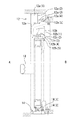
図1は、浴室折戸の姿図であり、図1Aは、浴室折戸を脱衣室側からみた姿図、図1Bは、浴室側からみた姿図である。
浴室折戸(以下、単に折戸という)1は、浴室折戸枠(以下、単に折戸枠という)2と、扉体3と、連結部材4で構成されている。
折戸枠2は、アルミニウムの形材で構成された上枠12、下枠14および両縦枠16、16を枠組みして構成され、浴室の開口部に取り付けられる。
扉体3は、ここでは2枚の扉体、即ち、連結部材4を介して折曲げ自在に連結された戸先側扉体3aと戸尻側扉体3bで構成され、折戸枠2に組み込まれ、即ち、開閉自在に支持されて、図示のように互いに突き合わせた状態になる。
折戸1は、戸先側、戸尻側の両扉体3a、3bを浴室A側に折り込むことにより開放し、折り込んだ両扉体3a、3bを開いて脱衣室B側に展開することで閉塞する。なお、図中18は、浴室側引手である。
First Embodiment First, the overall structure of a folding door according to an embodiment of the present invention will be schematically described.
FIG. 1 is a view of a bathroom folding door, FIG. 1A is a view of the bathroom folding door viewed from the undressing room side, and FIG. 1B is a view of the bathroom folding door viewed from the bathroom side.
A bathroom folding door (hereinafter simply referred to as a folding door) 1 includes a bathroom folding door frame (hereinafter simply referred to as a folding door frame) 2, a
The folding
The
Orifold
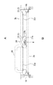
図2は、図1Bの折戸のX−X線に沿った縦断面図である。
折戸1において、上枠12は、間隔をおいて相互に平行に配設した上部上枠12aと下部上枠12bとから構成されており、この間隔に通気路(又は換気経路)10が設けられている。
FIG. 2 is a longitudinal cross-sectional view along line XX of the folding door of FIG. 1B.
In the folding
上部上枠12aは、浴室A側に形成した中空部12a(1)と、この中空部12a(1)を構成する脱衣室側壁12a(2)面から脱衣室B側に水平に延びる水平片12a(3)と、水平片12a(3)の見込み方向端部に形成したシール取付け部12a(4)で一体に形成されており、シール取付け部12a(4)には下向きの換気弁12a(5)が形成されている。
なお、換気弁12a(5)は、脱衣室Bからの空気の流入を許容しつつ、浴室Aからの湯気などを含んだ空気の流出を遮断するために設けたものであり、後述の連結部材4に設ける空気の通気路とは目的が相違する。
The upper
The
下部上枠12bは、中空部12b(1)からなり、中空部12b(1)の下側壁12b(2)の浴室A側には上レール部12b(3)が一体に形成されている。下側壁12b(2)の脱衣室B側端部から下向きにシール取付片12b(4)が延設されており、シール取付片12b(4)には、浴室A側に向かってシール片12b(5)が装着されている。
下枠14は、図示のように中空部14(1)と、中空部14(1)の脱衣室B側上端部から脱衣室B側に延在する床固定部14(2)を一体に備えている。
The lower
The
次に、浴室折戸の扉体3a、3bを折曲げ自在に連結する連結部材4について説明する。
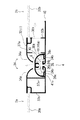
図3は、折戸を閉塞した状態を示す横断面図、図4は、浴室折戸の連結部材及び扉体の突合せ部分近傍を拡大して示す横断面図である。
左右の扉体3a、3bは、上下框(図示せず)と縦框32(1)、32(2)で構成する扉枠体と、扉枠体に装着されたパネル30a、30bで構成されている。両扉体3a、3bの互いに隣接した縦框(縦中框という)32(1)は、両扉体3a、3bの突合せ部(対向部分)34となる端部が開放された断面略コ字状に形成されている。連結部材4は両縦中框32(1)の略コ字状部分の内部に取り付けられており、それによって両扉体3a、3bを連結する。
Next, the connecting
FIG. 3 is a cross-sectional view showing a state in which the folding door is closed, and FIG. 4 is an enlarged cross-sectional view showing the vicinity of the butting portion of the connecting member of the bathroom folding door and the door.
The left and
連結部材4は、それ自体公知であり本発明を構成するものではないが、縦中框32(1)とほぼ同一長さを有する閉塞部材41と、閉塞部材41の長手方向の例えば4箇所に装着した4つの軸受け部材41cとを有する。上下4つの軸受け部材41cは、それぞれ閉塞部材41の内面に装着される。
The connecting
各縦中框32(1)の突合せ部34は、端部片34a、34bを有する断面略コ字状に形成されており、浴室A側の端部片34aの先端部は、閉塞部材41から隙間Gを設けて内側(脱衣室B側)に湾曲している。
一方、脱衣室B側の端部片34bの先端部には、軸受け部材41cに回動自在に軸支される折曲げ軸部36が一体に形成されている。折曲げ軸部36は、円弧状部分36aと平板状部分36bから成る断面略「フ」字状に形成され、各軸受け部材41cの軸受け部43内に配置されて、両扉体3a、3bのヒンジ機構を構成している。
扉体3a、3bを折り曲げて回動する際には、平板状部分36bの先端部36cがその回動支点となり、円弧状部分36aの外面は、軸受け部材41cの内面に当接しつつ摺動する。
The
On the other hand, a bent shaft portion 36 pivotally supported by the bearing member 41c is integrally formed at the tip end of the
When the
閉塞部材41は、脱衣室B側中央が開放された断面略半円状の中空形状に形成されており、脱衣室B側においては、突き合わせた縦中框32(1)間の隙間を閉塞する一方、浴室A側においては、既に述べたように、浴室A側の端部片34aの脱衣室B側に湾曲した先端部と、閉塞部材41との間には隙間Gが設けられている。
即ち、閉塞部材41の浴室A側の半円部41aは、浴室A側の端部片34aに隙間Gを存して対向し、折曲げ軸部36を中心に回動する浴室A側の端部片34aの先端部の回動軌跡に合致する円弧に形成されており、折戸の折り曲げ位置に関わらず隙間Gが維持される。
The closing
That is, the
縦中框32(1)は、図示のように、浴室A側の端部片34aと、脱衣室B側の端部片34bと、これらの端部片34a、34b間を連結する側壁37a、37bにより断面矩形の中空枠として構成されている。
ここで、側壁37a、37bには、その壁面にそれぞれ浴室A側の端部片34aと閉塞部材41との間の隙間Gと連通する開放口(気泡口とも云う)38a(浴室側開放口)、38b(脱衣室側開放口)が設けられており、浴室Aと脱衣室Bはこの隙間Gと各開放口38a、38bを通して連通している。
As shown in the figure, the vertical middle collar 32 (1) is an
Here, in the
したがって、折戸1を浴室A側に折り込み浴室A内の空気を押し込むと、押し込まれた空気は、隙間G、浴室側開放口38a、脱衣室側開放口38bを通して脱衣室Bに流れ、従来のように、扉体3a、3bを浴室A側に折り込んだときに、浴室A内の圧力上昇により折戸開放操作が重くなることや音鳴りがなく、スムーズに開放することができる。
Therefore, when the
なお、浴室側開放口38aと脱衣室側開放口38bは、それぞれ上下に位置をずらして配置することが好ましく、その際、浴室側開放口38aを下側にかつ脱衣室開放口38bを上側に配置することで、浴室Aで発生する水滴などが隙間G及び浴室側開放口38aを通過しても、脱衣室開放口38bを通過することが防止できる。したがって、この折戸1によれば、浴室A内でのシャワー散水時に濾水も飛散もなく、開放口を設けても止水性が確保できる。
また、浴室側開放口38a、脱衣室開放口38bは、それぞれ1個でも或いは下流側への水滴などの進入が防止できる限り、複数個であってもよい。
The
Each of the
本折戸1では、戸尻側の扉体3bにおける縦中框32(1)の脱衣室B側の端部片34bの折曲げ軸部36と反対側には延在部が例えば押出成形により一体に形成されており、ここでは、この形材からなる延在部を脱衣室側引手40として用いる。
脱衣室側引手40は、その見付け方向幅により側壁37bの脱衣室側開放口38bを覆い、脱衣室側から見えないよう目隠しの役割を果している。したがって、折戸1を脱衣室B側からみたとき、意匠上は従来の折戸と格別変わらず、外観を損なうことがない。加えて脱衣室側引手40は、縦中框32(1)の上下全長に渡って延設されているため、脱衣室側開放口38bは上下方向どの位置にあっても露出することがない。そのため、脱衣室側開放口38bの設置位置を自由に設定することができる。加えて、脱衣室側引手40は形材で形成されているため、従来の把手部品よりも安価な仕様とすることができる。
これらの作用効果は、以下で説明する他の実施形態においても共通に得ることができる。
In the
The dressing room side handle 40 covers the dressing
These effects and advantages can be commonly obtained in the other embodiments described below.
第2の実施形態
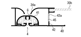
図5は、第2の実施形態に係る折戸の突合せ部近傍を示す図4と同様の図である。
第1の実施形態の折戸と第2の実施形態の折戸との違いは、第1の実施形態の折戸ではその縦中框は断面矩形の中空の形材で構成されているが、第2の実施形態では、板状の形材(側壁)42で構成されており、側壁42に設けた開放口42aにフィルタ45を設置した点である。その他の点では同じであるため、ここでは、相違する部分について説明する。
本実施形態において、フィルタ45は、例えば不織布や発泡性合成樹脂材など適宜の材料でできたそれ自体公知の通気性の防水フィルタであり、図示のように、開放口42aに設定される。
Second Embodiment FIG. 5 is a view similar to FIG. 4 showing the vicinity of a butt portion of a folding door according to a second embodiment.
The difference between the folding door of the first embodiment and the folding door of the second embodiment is that, in the folding door of the first embodiment, the vertical center is formed of a hollow section having a rectangular cross section, but the second embodiment In the embodiment, it is configured of a plate-like shaped member (side wall) 42, and the
In the present embodiment, the
本折戸1によれば、開放口42aにより折戸の開放時における浴室A側からの空気流の通路を確保しつつ、フィルタ45により浴室A側からの水滴などの侵入を防止することができる。
したがって、本実施形態の折戸1においても、第1の実施形態の折戸1と同様に、折戸1を浴室A側に折り込んだ時に重くなることがなく、スムーズに開放することができる等の効果が得られる。
なお、本実施形態のフィルタ45は、例えば、縦中框が中空枠である場合にように、縦中框を構成する横壁が複数あり、開放口が通気路に沿って複数ある場合には、その脱衣室側の開放口に取り付けることができる。
According to the
Therefore, also in the
In the
第3の実施形態
図6は、第3の実施形態に係る折戸1の突合せ部分近傍を示す図5と同様の図である。但し、ここでは、図5に示す防水用のフィルタ45の代わりに、シャッタ50が設けられている。図6Aはシャッタ50を開いた状態、図6Bはシャッタ50が閉じた状態を示す。
第3の実施形態の折戸において、図4と同じ部分についてはその説明を省略する。
シャッタ50は、例えば樹脂又はアルミニウム合金等の金属でできた板状のシャッタ部材52と、シャッタ部材52を開放口42aに当接する閉鎖位置と、開放口42aから離隔した開放位置に移動させる操作部材54とから成っている。
3rd Embodiment FIG. 6: is a figure similar to FIG. 5 which shows the abutment part vicinity of the
In the door according to the third embodiment, the description of the same parts as those in FIG. 4 will be omitted.
The
操作部材54は、脱衣室側引手40の脱衣室側外面上を摺動する摺動部材54aと、摺動部材54aの摺動面と反対側の面に一体に取り付けられた操作つまみ54bからなる。シャッタ50は、形材の脱衣室側引手40に設けたスリット(図示せず)を介して摺動部材54aの図示しない連結部に連結されている。なお、シャッタ部材52は、浴室Aからの空気流に押されて開放口42aを閉鎖しないように、適度の摺動抵抗を備えるか、或いは適宜の係止手段で離隔位置に係止できるようにする。
The operating
本実施形態において、折戸1を開くときは、操作つまみ54bを掴んでシャッタ部材52を開放口42aから離隔する方向に移動する。これにより開放口42aが開放されて、開放口42aと浴室A側の端部片34aと閉塞部材41との間の隙間Gが連通する。つまり、浴室Aと脱衣室Bが連通する。したがって、折戸1を浴室A側に折り込んだとき、押し込まれた浴室A内の空気は隙間と開放口42aを通って脱衣室Bに流れるため、折戸の開放操作が重くなるということはない。
折戸1が開放されたときは、操作つまみ54bをつまんで開放時とは逆の方向に移動させ、シャッタ部材52を開放口42aに当接して閉塞する。それによって、浴室A内で生じた水滴などはシャッタ50で遮断されるため、脱衣室B側に流入することはない。
なお、この折戸1では、シャッタ50を開いたまま浴室を使用すると、浴室Aからの水滴等が空気流と一緒に隙間Gから流入するが、板状のシャッタ部材52の表面に一旦当たり大部分はシャッタ部材52の表面を流下する。また、空気流もシャッタ部材52により蛇行するため、水滴が直接更衣室側に流出することはない。
なお、本実施形態のシャッタ50は、例えば、縦中框が中空枠である場合のように、縦中框を構成する横壁が複数あり、開放口が通気路に沿って複数ある場合には、その脱衣室側の開放口に取り付けることができる。
In the present embodiment, when the
When the
In this
In the case where the
第4の実施形態
図7は、第4の実施形態に係る折戸の突合せ部近傍を示す図4と同様の図であり、図7Aは回転弁が開いた位置を、また図7Bは回転弁が閉じた位置を示す図である。また、図8は、図7に示す折戸の突合せ部の縦断面図であり、図8Aは図7のA−A断面図で回転弁が開いた状態を、また、図8Bは図7のB−B断面図で回転弁が閉じた状態を示している。
本実施形態の折戸1は、図4に示す折戸1の縦中框32(1)内にさらに回転弁60を備えた点で、第1の実施形態と相違し、その他の点では第1の実施形態と同じである。したがって、ここでは縦中框32(1)の部分のみを実線で示し、その他の共通部分は破線で示している。
Fourth Embodiment FIG. 7 is a view similar to FIG. 4 showing the vicinity of the butt portion of a folding door according to a fourth embodiment, and FIG. 7A shows the position where the rotary valve is open and FIG. 7B shows the rotary valve It is a figure which shows a closed position. 8 is a longitudinal sectional view of the butt portion of the folding door shown in FIG. 7, FIG. 8A shows a state in which the rotary valve is open in the AA sectional view of FIG. 7 and FIG. The rotary valve has shown the state closed by -B sectional drawing.
The
回転弁60は、縦中框32(1)の中空部を構成する側壁37a、37bに形成された浴室側開放口38aと脱衣室側開放口38b(各位置は、第1の実施形態におけると同様に上下にずらして配置されている)間に配置されている。
即ち、回転弁60の弁体62は、図8A、8Bに示すように、翼板状に構成されており、弁体62の上端及び下端部に、縦中框32(1)の上端及び下端部に設けられた軸65a、65bが挿入される。また、弁体62の下端部は縦中框32(1)の底板上に配置されており、縦中框32(1)の底板の一部には弧状のテーパ―面つまりせり上がり部分64が軸65aに対して対称に設けられている。
The
That is, as shown in FIGS. 8A and 8B, the
図8Bに示す初期状態、即ち折戸1が閉じた状態においては、回転弁60の弁体62の底面はせり上がり部分64から外れた平坦な底板位置に位置している。
その状態で、折戸1を浴室A側に折り込むと、押し込んだ空気により浴室A側の端部片34aと閉塞部材41との間の隙間Gから空気が縦中框32(1)内に流入する。
この空気流が回転弁60の弁体62に当たり弁体62を軸65a、65bの回りで回動させる。その際、弁体62はその底面が縦中框32(1)の底板のせり上がり部分64に案内されて上昇する。
In the initial state shown in FIG. 8B, that is, in the state in which the
In that state, when the
The air flow strikes the
折戸1が開き、浴室A内と脱衣室B内の気圧が平衡して隙間Gから開放口38aに向かう空気流が停止すると弁体62の上昇は停止し、次に自重により逆回転しながらせり上がり部64に沿って下降して、元の平坦な底板位置に戻る。つまり、回転弁60は自動で最初の開放口の閉鎖位置に戻る。
本実施形態によれば、第1の実施形態の構成に加えて、縦中框32(1)内に回転弁60を配置したため、浴室Aから開放口38aに流入する水滴などは開放口38bに流入する前に回転弁60により遮断できる。そのため、脱衣室Bに水滴などが流入するのをより完全に防止することができる。
When the
According to the present embodiment, in addition to the configuration of the first embodiment, since the
なお、以上の説明では、浴室折戸の扉体は2枚であるとして説明したが3枚以上であってもよく、また、連結部材と縦中框の浴室側間の隙間G、開放口からなる通気路は、隣接する扉体のうち一方の扉体側にのみ設けたものとして説明したが、両方の扉体に設けてもよい。脱衣室側引手は縦中框と別部材で形成してもよい。 In the above description, the door of the bathroom folding door has been described as being two sheets, but may be three or more sheets, and it is composed of a gap G between the connecting member and the bathroom side of the vertical center and an opening Although an air passage was explained as what was provided only in one door side among adjacent doors, it may be provided in both doors. The dressing room side pull handle may be formed of a longitudinal center and a separate member.
1・・・折戸、2・・・折戸枠、3(3a、3b)・・・扉体、4・・・連結部材、12・・・上枠、14・・・下枠、16・・・縦枠、18・・・浴室側引手、32(1)・・・縦中框、34・・・突合せ部、34a、34b・・・端部片、37a、37b・・・側壁、38a、38b・・・開放口、40・・・脱衣室側引手、41・・・閉塞部材、42・・・側壁、42a・・・開放口、45・・・フィルタ、50・・・シャッタ、52・・・シャッタ部材、54・・・操作部材、54a・・・摺動部材、54b・・・操作つまみ、60・・・回転弁、62・・・弁体、64・・・せり上がり部分、65a、65b・・・軸。
DESCRIPTION OF
Claims (6)
前記折戸は、隣接する扉体の互いに隣接する縦中框に跨って配設されて前記扉体同士を折曲げ自在に連結する連結部材を備え、前記連結部材と少なくとも一方の縦中框の浴室側間に隙間を設け、前記少なくとも一方の縦中框には、前記隙間を介して浴室内と脱衣室内とを連通する通気路を形成する開放口が形成され、
前記縦中框の脱衣室側に、脱衣室側から前記開放口を遮る位置に引手を設けた浴室折戸。 A bathroom folding door comprising a folding door frame and a folding door supported openably and closably by the folding door frame, the folding door having at least two door bodies connected so as to be foldable toward the inside of the bathroom,
The folding door is provided with a connecting member which is disposed across the adjacent vertical middle bars of the adjacent door bodies and foldably connects the door bodies, and the bathroom of at least one vertical middle hook with the connecting member A gap is provided between the sides, and an opening is formed in the at least one longitudinal center to form an air passage communicating the inside of the bathroom with the undressing chamber through the gap .
The bathroom folding door which provided the puller in the position which interrupts | blocks the said opening from the undressing room side to the undressing room side of the said vertical middle rod .
前記開放口は前記縦中框を構成する側壁に設けられ、前記開放口に通気性の防水フィルタを備えた浴室折戸。 In the bathroom folding door according to claim 1,
The said opening is provided in the side wall which comprises the said longitudinal middle rod, The bathroom folding door provided with the breathable waterproof filter in the said opening.
前記開放口は前記縦中框を構成する側壁に設けられ、前記開放口に前記開放口を閉塞又は開放するシャッタを備えた浴室折戸。 In the bathroom folding door according to claim 1,
The bathroom fold door provided with the shutter which the said opening is provided in the side wall which comprises the said longitudinal center, and closes or opens the said opening in the said opening.
前記開放口は前記縦中框を構成する対向する側壁に設けられており、両側壁には、それぞれ前記隙間に連通する通気路を形成する浴室側開放口と脱衣室側開放口が形成され、前記脱衣室側開放口が前記浴室側開放口よりも高い位置に形成されている浴室折戸。 In the bathroom folding door according to claim 1,
The opening is provided on the opposing side walls constituting the longitudinal middle ridge, and a bathroom side opening and an undressing room side opening forming an air passage communicating with the gap are formed on both side walls, The bathroom folding door in which the said opening room side opening is formed in the position higher than the said bathroom side opening.
前記対向する側壁間に回転弁が配置されており、
前記回転弁は、前記隙間及び浴室側開放口を通して流入する空気流により回転して前記脱衣室側開放口を開放し、浴室側からの空気流の停止により前記脱衣室側開放口を閉塞する位置に戻る浴室折戸。 In the bathroom folding door according to claim 4,
A rotary valve is disposed between the opposing side walls,
The rotary valve is rotated by the air flow flowing in through the gap and the bathroom side opening port to open the dressing room side opening port, and the position to close the dressing room side opening port by stopping the air flow from the bathroom side Return to the bathroom Orido.
前記引手は、前記縦中框に一体に形成されている浴室折戸。 In the bathroom folding door according to any one of claims 1 to 5,
The said handle is a bathroom folding door integrally formed in the said longitudinal middle rod .
Priority Applications (1)
| Application Number | Priority Date | Filing Date | Title |
|---|---|---|---|
| JP2015064316A JP6504871B2 (en) | 2015-03-26 | 2015-03-26 | Bath door |
Applications Claiming Priority (1)
| Application Number | Priority Date | Filing Date | Title |
|---|---|---|---|
| JP2015064316A JP6504871B2 (en) | 2015-03-26 | 2015-03-26 | Bath door |
Related Child Applications (1)
| Application Number | Title | Priority Date | Filing Date |
|---|---|---|---|
| JP2018172221A Division JP2019007346A (en) | 2018-09-14 | 2018-09-14 | Folding door for bathroom |
Publications (3)
| Publication Number | Publication Date |
|---|---|
| JP2016183506A JP2016183506A (en) | 2016-10-20 |
| JP2016183506A5 JP2016183506A5 (en) | 2018-11-08 |
| JP6504871B2 true JP6504871B2 (en) | 2019-04-24 |
Family
ID=57241630
Family Applications (1)
| Application Number | Title | Priority Date | Filing Date |
|---|---|---|---|
| JP2015064316A Active JP6504871B2 (en) | 2015-03-26 | 2015-03-26 | Bath door |
Country Status (1)
| Country | Link |
|---|---|
| JP (1) | JP6504871B2 (en) |
Families Citing this family (2)
| Publication number | Priority date | Publication date | Assignee | Title |
|---|---|---|---|---|
| JP6145235B1 (en) * | 2017-02-24 | 2017-06-07 | 三協立山株式会社 | Bathroom folding door |
| JP6389921B2 (en) * | 2017-05-11 | 2018-09-12 | 三協立山株式会社 | Bathroom folding door |
Family Cites Families (6)
| Publication number | Priority date | Publication date | Assignee | Title |
|---|---|---|---|---|
| JPS593988U (en) * | 1982-06-30 | 1984-01-11 | 松下電工株式会社 | Folding door connection device |
| JPS6256690U (en) * | 1985-09-30 | 1987-04-08 | ||
| JPH0627731Y2 (en) * | 1988-10-05 | 1994-07-27 | 三和シヤッター工業株式会社 | Orido connection structure |
| JP3161772B2 (en) * | 1991-09-10 | 2001-04-25 | ミサワホーム株式会社 | Door with ventilator |
| JP4730906B2 (en) * | 2006-02-24 | 2011-07-20 | Ykk Ap株式会社 | Opening frame with air passage |
| PL390218A1 (en) * | 2010-01-18 | 2011-08-01 | Jacek Olaf Klimaszewski | Envelope heat exchanger |
-
2015
- 2015-03-26 JP JP2015064316A patent/JP6504871B2/en active Active
Also Published As
| Publication number | Publication date |
|---|---|
| JP2016183506A (en) | 2016-10-20 |
Similar Documents
| Publication | Publication Date | Title |
|---|---|---|
| JP2006076563A (en) | Air vent, in particular for vehicle | |
| DK2791452T3 (en) | Ventilation device for a window or door | |
| JP6504871B2 (en) | Bath door | |
| JP4730906B2 (en) | Opening frame with air passage | |
| JPH04231576A (en) | Window | |
| JP5290806B2 (en) | Joinery | |
| JP4802127B2 (en) | Joinery | |
| JP6449037B2 (en) | Joinery | |
| JP2006274537A (en) | Bathroom door | |
| JP2011219955A (en) | Fixture | |
| JP2019007346A (en) | Folding door for bathroom | |
| JP6419014B2 (en) | Joinery | |
| JP5286124B2 (en) | Joinery | |
| ITPN20070033A1 (en) | WINDOW WITH ADJUSTABLE ROOF PANES | |
| JP6501256B2 (en) | Folding door | |
| JP6375182B2 (en) | Joinery | |
| US1254216A (en) | Ventilator. | |
| JP2016183506A5 (en) | ||
| JP6968555B2 (en) | Joinery | |
| JP7422575B2 (en) | fittings | |
| JP2019119987A (en) | Fixture | |
| JP6494324B2 (en) | Joinery | |
| JP5861120B2 (en) | Door device | |
| JP7008281B2 (en) | Joinery | |
| US624888A (en) | Guera |
Legal Events
| Date | Code | Title | Description |
|---|---|---|---|
| A621 | Written request for application examination |
Free format text: JAPANESE INTERMEDIATE CODE: A621 Effective date: 20171206 |
|
| A977 | Report on retrieval |
Free format text: JAPANESE INTERMEDIATE CODE: A971007 Effective date: 20180925 |
|
| A521 | Written amendment |
Free format text: JAPANESE INTERMEDIATE CODE: A523 Effective date: 20180927 |
|
| A131 | Notification of reasons for refusal |
Free format text: JAPANESE INTERMEDIATE CODE: A131 Effective date: 20181016 |
|
| A521 | Written amendment |
Free format text: JAPANESE INTERMEDIATE CODE: A523 Effective date: 20181205 |
|
| TRDD | Decision of grant or rejection written | ||
| A01 | Written decision to grant a patent or to grant a registration (utility model) |
Free format text: JAPANESE INTERMEDIATE CODE: A01 Effective date: 20190326 |
|
| A61 | First payment of annual fees (during grant procedure) |
Free format text: JAPANESE INTERMEDIATE CODE: A61 Effective date: 20190326 |
|
| R150 | Certificate of patent or registration of utility model |
Ref document number: 6504871 Country of ref document: JP Free format text: JAPANESE INTERMEDIATE CODE: R150 |