JP6502953B2 - Occlusal adjustment structure for each treatment plan - Google Patents
Occlusal adjustment structure for each treatment plan Download PDFInfo
- Publication number
- JP6502953B2 JP6502953B2 JP2016553476A JP2016553476A JP6502953B2 JP 6502953 B2 JP6502953 B2 JP 6502953B2 JP 2016553476 A JP2016553476 A JP 2016553476A JP 2016553476 A JP2016553476 A JP 2016553476A JP 6502953 B2 JP6502953 B2 JP 6502953B2
- Authority
- JP
- Japan
- Prior art keywords
- teeth
- jaw
- occlusal
- occlusal adjustment
- shell
- Prior art date
- Legal status (The legal status is an assumption and is not a legal conclusion. Google has not performed a legal analysis and makes no representation as to the accuracy of the status listed.)
- Active
Links
- 239000000463 material Substances 0.000 claims description 16
- 241000282465 Canis Species 0.000 claims description 14
- 230000001105 regulatory effect Effects 0.000 claims 1
- 210000001847 jaw Anatomy 0.000 description 125
- 210000004283 incisor Anatomy 0.000 description 12
- 238000000034 method Methods 0.000 description 12
- 206010061274 Malocclusion Diseases 0.000 description 11
- 238000005520 cutting process Methods 0.000 description 11
- 208000006650 Overbite Diseases 0.000 description 9
- 210000000214 mouth Anatomy 0.000 description 9
- 230000008859 change Effects 0.000 description 7
- 238000012937 correction Methods 0.000 description 7
- 210000003464 cuspid Anatomy 0.000 description 6
- 210000000887 face Anatomy 0.000 description 6
- 230000036339 tooth positioning Effects 0.000 description 6
- 238000004364 calculation method Methods 0.000 description 5
- 210000004763 bicuspid Anatomy 0.000 description 4
- 238000013500 data storage Methods 0.000 description 4
- 230000006870 function Effects 0.000 description 4
- 230000008569 process Effects 0.000 description 4
- 238000000605 extraction Methods 0.000 description 3
- 238000003384 imaging method Methods 0.000 description 3
- 230000003993 interaction Effects 0.000 description 3
- 230000000750 progressive effect Effects 0.000 description 3
- 230000009467 reduction Effects 0.000 description 3
- 208000012287 Prolapse Diseases 0.000 description 2
- 238000013459 approach Methods 0.000 description 2
- 230000008901 benefit Effects 0.000 description 2
- 210000002455 dental arch Anatomy 0.000 description 2
- 230000002349 favourable effect Effects 0.000 description 2
- 238000004519 manufacturing process Methods 0.000 description 2
- 239000002184 metal Substances 0.000 description 2
- 208000024891 symptom Diseases 0.000 description 2
- 210000001519 tissue Anatomy 0.000 description 2
- 239000013598 vector Substances 0.000 description 2
- 208000006440 Open Bite Diseases 0.000 description 1
- 230000009471 action Effects 0.000 description 1
- 230000001154 acute effect Effects 0.000 description 1
- 230000006978 adaptation Effects 0.000 description 1
- 238000004458 analytical method Methods 0.000 description 1
- 239000013590 bulk material Substances 0.000 description 1
- 239000002537 cosmetic Substances 0.000 description 1
- 210000004513 dentition Anatomy 0.000 description 1
- 230000000994 depressogenic effect Effects 0.000 description 1
- 238000013461 design Methods 0.000 description 1
- 238000001125 extrusion Methods 0.000 description 1
- 230000001815 facial effect Effects 0.000 description 1
- 230000008821 health effect Effects 0.000 description 1
- 239000007943 implant Substances 0.000 description 1
- 230000006698 induction Effects 0.000 description 1
- 239000003562 lightweight material Substances 0.000 description 1
- 230000004048 modification Effects 0.000 description 1
- 238000012986 modification Methods 0.000 description 1
- 229920000642 polymer Polymers 0.000 description 1
- 238000003825 pressing Methods 0.000 description 1
- 238000012545 processing Methods 0.000 description 1
- 230000004044 response Effects 0.000 description 1
- 230000002441 reversible effect Effects 0.000 description 1
- 238000001356 surgical procedure Methods 0.000 description 1
- 238000003856 thermoforming Methods 0.000 description 1
- 230000036346 tooth eruption Effects 0.000 description 1
- 239000012780 transparent material Substances 0.000 description 1
- 238000007666 vacuum forming Methods 0.000 description 1
- 230000000007 visual effect Effects 0.000 description 1
Images


Classifications
-
- A—HUMAN NECESSITIES
- A61—MEDICAL OR VETERINARY SCIENCE; HYGIENE
- A61C—DENTISTRY; APPARATUS OR METHODS FOR ORAL OR DENTAL HYGIENE
- A61C7/00—Orthodontics, i.e. obtaining or maintaining the desired position of teeth, e.g. by straightening, evening, regulating, separating, or by correcting malocclusions
- A61C7/002—Orthodontic computer assisted systems
-
- A—HUMAN NECESSITIES
- A61—MEDICAL OR VETERINARY SCIENCE; HYGIENE
- A61C—DENTISTRY; APPARATUS OR METHODS FOR ORAL OR DENTAL HYGIENE
- A61C7/00—Orthodontics, i.e. obtaining or maintaining the desired position of teeth, e.g. by straightening, evening, regulating, separating, or by correcting malocclusions
- A61C7/08—Mouthpiece-type retainers or positioners, e.g. for both the lower and upper arch
-
- A—HUMAN NECESSITIES
- A61—MEDICAL OR VETERINARY SCIENCE; HYGIENE
- A61C—DENTISTRY; APPARATUS OR METHODS FOR ORAL OR DENTAL HYGIENE
- A61C7/00—Orthodontics, i.e. obtaining or maintaining the desired position of teeth, e.g. by straightening, evening, regulating, separating, or by correcting malocclusions
- A61C7/36—Devices acting between upper and lower teeth
-
- G—PHYSICS
- G06—COMPUTING; CALCULATING OR COUNTING
- G06F—ELECTRIC DIGITAL DATA PROCESSING
- G06F30/00—Computer-aided design [CAD]
Landscapes
- Health & Medical Sciences (AREA)
- Engineering & Computer Science (AREA)
- Animal Behavior & Ethology (AREA)
- Life Sciences & Earth Sciences (AREA)
- Dentistry (AREA)
- General Health & Medical Sciences (AREA)
- Public Health (AREA)
- Veterinary Medicine (AREA)
- Oral & Maxillofacial Surgery (AREA)
- Epidemiology (AREA)
- General Engineering & Computer Science (AREA)
- Physics & Mathematics (AREA)
- Theoretical Computer Science (AREA)
- Computer Hardware Design (AREA)
- Geometry (AREA)
- General Physics & Mathematics (AREA)
- Evolutionary Computation (AREA)
- Dental Tools And Instruments Or Auxiliary Dental Instruments (AREA)
- Architecture (AREA)
- Software Systems (AREA)
- Prostheses (AREA)
Description
本開示は、全般的には、歯科治療の分野に関する。より具体的には、本開示は、治療計画ごとの咬合調整構造物の為のシステム、方法、コンピューティング装置可読媒体、及び装置に関する。 The present disclosure relates generally to the field of dental care. More specifically, the present disclosure relates to systems, methods, computing device readable media, and devices for occlusal adjustment structures per treatment plan.
歯科治療は、例えば、修復及び/又は歯列矯正の処置を含んでよい。修復処置は、歯科補綴材料(例えば、クラウン、ブリッジインレー、オンレー、ベニヤ等)を患者の口腔内に植え付けるように設計されてよい。歯列矯正処置は、美容的外観及び/又は歯科機能を向上させる為に、歯並びの悪い歯を再配置し、咬合構成を変更することを含んでよい。歯列矯正再配置は、例えば、一定期間にわたって1つ以上の歯に制御された力をかけることによって達成可能である。 Dental treatment may include, for example, restorative and / or orthodontic treatment. The restoration procedure may be designed to implant a dental prosthetic material (eg, crown, bridge inlay, onlay, veneer, etc.) into the patient's mouth. Orthodontic treatment may include repositioning the misaligned teeth and changing the occlusal configuration to improve cosmetic appearance and / or dental function. Orthodontic repositioning can be accomplished, for example, by applying a controlled force to one or more teeth over a period of time.
一例として、歯列矯正再配置は、配置器具を使用して歯を再変性する歯科的プロセスによって行われてよい。そのような器具は、ユーザの歯に略順応するものの、現在の歯構成とは若干ずれている、「アライナ」と呼ばれる、弾性特性を有する材料の薄いシェルを利用してよい。 As an example, orthodontic repositioning may be performed by a dental process that reshapes the teeth using a placement tool. Such a device may utilize a thin shell of material with elastic properties, called an "aligner", that conforms substantially to the user's teeth but is slightly offset from the current tooth configuration.
そのような器具を歯の上に配置することにより、制御された力を特定の場所にかけて、新しい構成まで歯を徐々に動かすことが可能である。漸進的な構成をなす連続する器具を使用してこのプロセスを繰り返すことにより、一連の中間的な配列を経て最終的な所望の配列まで歯を動かすことが可能である。 By placing such an instrument on the teeth, it is possible to move the teeth gradually to a new configuration, with controlled forces on specific locations. By repeating this process using a series of progressive devices, it is possible to move the teeth through the series of intermediate arrangements to the final desired arrangement.
そのようなシステムでは、典型的には、軽量且つ/又は透明な材料を利用して、次々に使用することが可能な一連の器具を用意し、歯が動いたら、それらの歯を更に動かす為に次の器具を投入することが可能である。 Such systems typically utilize lightweight and / or transparent materials to provide a series of instruments that can be used one after another to move the teeth further as they move. The following instruments can be inserted into the
様々な場合において、患者が不正咬合を有していることがあり、その場合、患者の歯は正しく並んでいない。不正咬合の一例として、深い咬合があり、これは、患者の下の歯に上の歯が重なり、下の切歯が上顎歯列弓の歯肉組織と接触する過蓋咬合の急性症例である。深い咬合は、美的問題及び/又は健康への影響の問題となる可能性があり、特に、上の歯の歯根へのダメージ、上顎歯列弓の歯肉組織へのダメージ、及び/又は上の歯との摩擦接触による下の歯の摩耗などが問題となる可能性がある。 In various cases, the patient may have a malocclusion, in which case the patient's teeth are not aligned properly. An example of malocclusion is a deep occlusion, which is an acute case of an overcap occlusion where the upper teeth overlap the lower teeth of the patient and the lower incisor contacts the gingival tissue of the upper dental arch. A deep occlusion can be a problem of aesthetics and / or health effects, in particular damage to the roots of the upper teeth, damage to the gum tissue of the upper dental arch, and / or the upper teeth. Wear of the lower teeth due to frictional contact with it may be a problem.
患者における深い咬合の症状を矯正する既存の方法として、前歯(例えば、切歯及び/又は犬歯)の圧下、及び/又は臼歯(例えば、小臼歯及び/又は臼歯)の挺出などが考えられる。臼歯の廷出は、特に、バイトターボ(例えば、上の前歯の後面(舌側面)に接着されて、上下顎の臼歯同士の接触を減らして萌出を促進する金属ブロック)、(例えば、未成年患者の)臼歯の萌出を可能にしながら前の歯列と接触する前歯咬合プレート、(例えば、咬合面が傾斜したブロックが、1つは上の歯列の上に配置され、1つは下の歯列の上に配置されることにより、臼歯同士の接触を減らす)ツインブロックを使用することによって促進されることが可能である。しかしながら、成人患者の場合、臼歯の挺出は不安定な結果につながる可能性がある。前歯の圧下は、特に、アンカーベンド(例えば、切歯に上向きの力をかける為に使用される、臼歯上の金属アンカー)、Jフックヘッドギア、拡張ねじ、小臼歯及び/又は犬歯をバイパスして、臼歯と切歯の間の距離を長くすることによって、低減された力を維持するバイパス歯列弓ワイヤにより、促進可能である。患者における深い咬合の症状を矯正する別の既存の方法として、歯列矯正手術が考えられる。 As an existing method of correcting deep occlusion symptoms in a patient, pressure reduction of the anterior teeth (e.g., incisors and / or canines) and / or extraction of molars (e.g., premolars and / or molars) may be considered. In particular, a tooth bite of a molar is attached to a bite turbo (eg, a metal block attached to the posterior surface (lingual surface) of the upper anterior tooth to reduce contact between the molars of the upper and lower jaws and promote extrusion) (eg, underage) An occlusal plate in contact with the anterior row of teeth while allowing the extraction of the molars of the patient) (for example, a block with an inclined occlusal surface, one located above the upper row, one below the row) Being placed on the dentition can be facilitated by using a twin block) which reduces the contact between the molars. However, in the case of adult patients, molar eruption can lead to erratic results. The reduction of the anterior teeth, in particular, bypasses the anchor bend (for example, a metal anchor on the molars used for applying an upward force to the incisors), J-hook headgear, expansion screws, molars and / or canines. , By increasing the distance between the molars and the incisors, it can be facilitated by a bypass arch wire which maintains a reduced force. Orthodontic surgery may be considered as another existing method of correcting deep occlusion symptoms in patients.
本発明は、背景技術の課題を解決するためのものである。 The present invention is for solving the problems of the background art.
幾つかの既存の方法と異なり、本開示の幾つかの実施形態は、治療ごとに異なる様式で歯配置器具の上に幾つかの咬合調整構造物が配置された、歯配置器具(例えば、アライナ)を特徴とする。例えば、咬合調整構造物は、器具に関連付けられた、治療の一段階に従って配置されてよい。一連の器具のうちの1つ、幾つか、又は全ての器具に、各器具に関連付けられた、治療計画の各段階に固有の(例えば、形状及び位置が固有の)咬合調整構造物が配置されてよい。実施形態によっては、咬合調整構造物は、器具と同じ材料で形成されてよく、且つ/又は、器具と同時に形成されてよい。 Unlike some existing methods, some embodiments of the present disclosure have a tooth placement device (e.g., an aligner) in which several occlusal adjustment structures are disposed on the tooth placement device in a manner that differs from treatment to treatment. ) Is characterized. For example, the occlusal adjustment structure may be arranged according to one stage of treatment associated with the device. One, some or all of the instruments in the series are placed with an occlusal adjustment structure (e.g., unique in shape and position) specific to each stage of the treatment plan associated with each instrument You may In some embodiments, the occlusal adjustment structure may be formed of the same material as the device and / or formed simultaneously with the device.
本開示の以下の詳細説明では、本開示の一部を成す添付図面を参照する。添付図面には、本開示の幾つかの実施形態がどのように実施されうるかが例示されている。これらの実施形態は、当業者であれば本開示の実施形態を実施できるように十分詳細に記載されており、又、当然のことながら、他の実施形態も利用されてよく、本開示の範囲を逸脱しない限り、プロセス及び/又は構造の変更が行われてよい。本明細書で使用されている「幾つかの」特定の物は、1つ以上のそのような物を意味してよい(例えば、幾つかの咬合調整構造物は、1つ以上の咬合調整構造物を意味してよい)。 The following detailed description of the present disclosure refers to the accompanying drawings that form a part of the present disclosure. The accompanying drawings illustrate how some embodiments of the present disclosure may be practiced. These embodiments are described in sufficient detail to enable those skilled in the art to practice the embodiments of the present disclosure, and it is understood that other embodiments may be utilized, and the scope of the present disclosure. Changes in process and / or structure may be made without deviating from. As used herein, "some" specific may mean one or more such things (e.g. some occlusal adjustment structures are one or more occlusal adjustment structures May mean something).
本明細書の各図面は、最初の1つ以上の桁が図面番号に対応し、残りの桁が図面中の要素又は構成要素を識別するという番号付け規則に従う。異なる図面間で同様の要素又は構成要素は、同様の桁を使用することにより識別可能である。例えば、106は、図1の要素「06」を参照することが可能であり、図6の同様の要素は「606」として参照することが可能である。当然のことながら、本明細書に記載の様々な実施形態において示されている要素を追加、交換、及び/又は除去することにより、本開示の新たな実施形態を追加することが可能である。更に、当然のことながら、図面に示されている各要素の比率や相対尺度は、本発明の特定の実施形態を例示することを意図したものであって、限定の意味に解釈されるべきではない。 Each drawing in this specification follows the numbering convention that the first one or more digits correspond to the drawing number and the remaining digits identify an element or component in the drawing. Similar elements or components between different drawings can be identified by using similar digits. For example, 106 may refer to element "06" of FIG. 1, and similar elements of FIG. 6 may be referred to as "606". It will be appreciated that new embodiments of the present disclosure may be added by adding, replacing, and / or removing the elements shown in the various embodiments described herein. Furthermore, it is to be understood that the proportions and relative measures of each element shown in the drawings are intended to illustrate particular embodiments of the present invention and should be interpreted in a limiting sense. Absent.
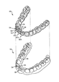
図1は、本開示の1つ以上の実施形態による歯位置調整器具102の斜視図を示しており、ここでは、一連の歯104に幾つかの咬合調整構造物106が貼り付けられている。本開示による器具は、実施形態によっては、複数の漸進的歯位置調整器具を含んでよい。図1に示された器具102のような器具は、幾つか適切な用途がある中でも特に、顎内の個々の歯の漸進的再配置に作用するなどして、治療計画を漸進的に実施する為に利用されてよい。器具102のような器具は、本開示の1つ以上の実施形態に従って調整された、幾つかの歯の位置を取得した仮の歯型に従って製作されてよい。
FIG. 1 shows a perspective view of a
器具は、歯科治療に関連して歯の配置を仕上げて保持する為の、任意の配置器、保持器、及び/又は他の取り外し可能器具を含んでよい。これらの器具は、治療計画の実施時に治療の専門家によって利用されてよい。例えば、治療計画は、本明細書に記載の型に従って作成された一連の器具の使用を含んでよい。 The device may include any deployer, retainer, and / or other removable device for finishing and holding the placement of teeth in connection with dental treatment. These devices may be utilized by the treatment specialist when performing the treatment plan. For example, a treatment plan may include the use of a series of devices made in accordance with the types described herein.
器具(例えば、図1の器具102)は、例えば、ポリマーシェルで製作されてよく、且つ/又は、他の材料で形成されてよく、中に複数のキャビティを有する(例えば、キャビティ107−1、キャビティ107−2、ここではまとめてキャビティ107と称する)。キャビティ107は、1つ以上の歯104を受け、且つ/又は、顎の1つ以上の歯104に力をかけて、1つの歯配列から次の歯配列へと再配置するように、設計(例えば、整形)されてよい。シェルは、上顎及び/又は下顎にある歯104のうちの幾つか、又は多くの場合には全てに、ぴったりかぶせられるように設計されてよい。
The device (eg,
器具102は、シェルと同じ材料で形成された幾つかの咬合調整構造物106を含んでよい。実施形態によっては、咬合調整構造物106は、シェルとの連続体として、シェルと同じ材料で形成されてよい。咬合調整構造物106は、シェルと同時に(例えば、同じバルク材料で)形成されてよく、例えば、ユーザの歯を表すデータに基づいて形成された歯型の上に材料が真空形成される真空形成プロセス中に形成されてよい。
The
シェルは、(例えば、各キャビティ107が歯に対応する)キャビティ107を含んでよい。咬合調整構造物106は、キャビティ107の一部であってよい。キャビティ107−3のような、咬合調整構造物106を含まないキャビティは、特定の歯と嵌合するように整形されてよい。例えば、キャビティ107−3は、キャビティ107−3内で受けられる、対応する歯の3つの面と嵌合するように整形されてよい。この3つの面は、前面(顔側面)128、後面(舌側面)126、及び咬合面(切縁面)124であってよい。キャビティ107−3は、(例えば、その特定の歯を所望の構成に並べることを促進する為に)その特定の歯の現在の構成から若干ずれていてよいが、器具102の装着時にキャビティ107−3とその特定の歯との間の空間があまりないように、キャビティ107−3は、その特定の歯の形状と略一致していてよい。
The shell may include cavities 107 (e.g., each cavity 107 corresponds to a tooth).
これに対し、キャビティ107−1のような、咬合調整構造物106を含むキャビティは、特定の歯の2つの面と嵌合するように整形されてよい。切歯又は犬歯の場合、この2つの面は、前面(顔側面)128及び咬合面(切縁面)124であってよい。キャビティ107−1の後面(舌側面)126は、そこから延びる咬合調整構造物106を含んでよい。咬合調整構造物106は、特定の歯に装着されたときに、その歯と咬合調整構造物106との間に空間が存在するように、キャビティ107−1の一部を成してよい。図7B及び図7Cは、この空間をより詳細に示している。
In contrast, a cavity containing
咬合調整構造物106は、器具102から口の奥に向かって(顔側−舌側方向に)延びてよく、器具102が装着されることを意図された顎と対向する顎の歯と当接するように設計されてよい。例えば、器具102は、ユーザの上顎の歯にぴったりかぶせられるように設計されてよく、咬合調整構造物106は、ユーザの下顎の歯と当接するように設計されてよい。各咬合調整構造物106の形状(例えば、サイズ及び/又は輪郭、角度等)及び位置(例えば、キャビティ上の場所)は、器具102の設計の目的となった治療計画の一段階に固有のものであってよい。例えば、治療計画に従って作成された連続する器具群は、それぞれ、形状及び/又は位置が異なる咬合調整構造物106を有してよい。特定の咬合調整構造物106は、対向する顎の特定の歯との当接状態、意図された用途、及び咬合調整構造物106がかぶせられる歯の向きのうちの少なくとも1つに基づく、治療計画の特定の段階に固有の形状及び位置を有してよい。治療の特定段階に固有の形状及び位置を有する咬合調整構造物106は、治療の各段階に固有ではなく、従って、使用されている間の治療段階における所望の矯正を正確に行うことができない、汎用的且つ/又は均一のアタッチメントを使用する幾つかの既存の方法より有利となりうる。そのような不正確な治療は、幾つかある弱点の中でも特に、治療計画の長期化、治療計画の見直しの必要、及び/又はユーザの余計な不快感につながる可能性がある。これに対し、本開示の幾つかの実施形態は、治療の、より適時の、より正確な、且つ/又は、より快適な実施を可能にする。
The
実施形態によっては、キャビティ107の咬合面(切縁面)124に対向する、キャビティ107のエッジ101は、ユーザの歯肉線108を越えて延びるように整形されてよい。シェルの、顎の歯肉線108を越えて延びる部分は、(例えば、咬合調整構造物106にかかる幾つかの力に反する)逆の力を顎の他の部分に分散させることに役立ちうる。
In some embodiments, the
具体的には示されていないが、実施形態によっては、治療計画の特定の段階において、上側器具(ユーザの上顎の歯にぴったりかぶせられるように設計された器具)と下側器具(ユーザの下顎の歯にぴったりかぶせられるように設計された器具)の両方が幾つかの咬合調整構造物を含むことが可能である。治療計画の特定の段階が、上側器具及び下側器具のうちの一方のみに咬合調整構造物を含むことも可能である。治療計画の特定の段階が、上側器具にも下側器具にも咬合調整構造物を全く含まないことも可能である。治療計画の特定の段階が、切歯、犬歯、小臼歯、及び/又は臼歯、及び/又はこれらの任意の組み合わせに対応するキャビティ上に咬合調整構造物を含むことも可能である。 Although not specifically shown, in certain embodiments of the treatment plan, the upper device (the device designed to fit over the teeth of the user's upper jaw) and the lower device (the lower jaw of the user (in some embodiments) It is possible that both of the devices designed to fit snugly on one's teeth include several occlusal adjustment structures. It is also possible that certain stages of the treatment plan include an occlusal adjustment structure in only one of the upper and lower appliances. It is also possible that certain stages of the treatment planning do not include any occlusal adjustment structures in either the upper or lower appliances. It is also possible that certain stages of the treatment plan include occlusal adjustment structures on cavities corresponding to incisors, canines, premolars and / or molars, and / or any combination thereof.
上側器具上の咬合調整構造物は、下顎の歯と当接するように設計されてよく、下側器具上の咬合調整構造物は、上顎の歯と当接するように設計されてよい。本明細書では、「対向する顎の歯と当接するように設計され」ている咬合調整構造物は、その咬合調整構造物が当接するように設計されている、対向する顎の歯に別の器具がかぶせられていてもいなくてもよいことを意味している。実施形態によっては、(例えば、図7Dに関して例示及び説明されるように)第1の器具のキャビティ上の咬合調整構造物が、対向する顎にかぶせられた第2の器具のキャビティ上の対応する突出構造物と当接するように設計されてよい。 The occlusal adjustment structure on the upper device may be designed to abut the teeth of the lower jaw, and the occlusal adjustment structure on the lower device may be designed to abut the teeth on the upper jaw. As used herein, an occlusal adjustment structure that is "designed to abut against teeth of the opposing jaw" is another tooth on the opposing jaw that is designed to abut the occlusal adjustment structure. It means that the device may or may not be covered. In some embodiments, the occlusal adjustment structure on the cavity of the first device (eg, as illustrated and described with respect to FIG. 7D) is the corresponding on the cavity of the second device overlaid on the opposing jaw. It may be designed to abut the projecting structure.
上側器具は、上の前歯を受けるように設計されたキャビティ107の後ろ側(例えば、舌側)に幾つかの咬合調整構造物106を含んでよい。この幾つかの咬合調整構造物106は、ユーザの咬合時に(例えば、ユーザの臼歯間の離開咬合を実現するように)下の前歯と当接し、下の前歯からの本来の力を受けることが可能である。実施形態によっては、器具102は、(ユーザの咬合によって発生する本来の力に反する)逆の力を上の臼歯列に選択的に分散させるように設計されてよい。
The upper device may include several
咬合調整構造物106は、上下顎間の離開咬合を実現するように設計されてよい。上下顎間の離開咬合を実現することにより、上顎と下顎の垂直方向関係の調整(例えば、矯正)が可能であってよい。即ち、咬合調整構造物106は、上顎と下顎の垂直方向関係、及び/又は、上顎と下顎のそれぞれの歯同士の垂直方向関係の調整を行うように設計されてよく、且つ、その調整を行うことを意図されてよい。実施形態によっては、器具102は、咬合調整構造物106が上下顎間の離開咬合を実現する一方で、器具102が装着される幾つかの歯104を再配置するように設計されてよい。上下顎間の離開咬合を実現することは、上下顎上の器具同士の(例えば、咬合調整構造物106の場所以外での)相互干渉(例えば、接触、力のかけ合いを可能にすること等)を防ぐことに役立ちうる。上下顎間の離開咬合を実現することにより、ユーザの咬合平面(例えば、グローバル咬合平面)を調整することが可能になる。そのような調整は、(例えば、器具102が装着されている間の)一時的なものであってよく、且つ/又は、(例えば、臼歯などの歯の挺出を可能にすることにより)より永続的なものであってよい。例えば、咬合調整構造物106は、ユーザの咬合時に、対向する臼歯間の離開咬合を実現するように設計されてよい(例えば、実施形態によっては、ユーザの幾つかの前歯が、対向する顎に装着された器具上の咬合調整構造物106と接触してよく、これによって、ユーザの臼歯同士の咬合を防ぐことが可能である)。本明細書では、「離開咬合」は、上下顎の対応する歯同士の間に空間を設けることによって、それらの歯同士が結合及び/又は接触しないようにすることを含む。
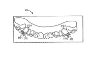
図2は、本開示の幾つかの実施形態による、顎のデジタルモデル214の斜視図を示しており、ここでは、幾つかの咬合調整構造物210が切歯上に配置されている。本開示の幾つかの実施形態は、非過渡的コンピューティング装置可読媒体内に固定されてよい、プロセッサによって実行可能な命令(例えば、ソフトウェア)を含み、これらの命令は、(例えば、歯、歯根、歯肉、及び/又は支持構造物等を含む)ユーザの顎をモデリングする。これらの命令は、幾つかある調整の中でも特に、本明細書に記載の一連の器具を適用することによって、ユーザの歯及び/又は咬合を漸進的に調整する治療計画を作成及び/又は修正する為に実行されてよい。これらの命令は、デジタルモデル214に対応する物理型の(例えば、ステレオリソグラフィなどのラピッドプロトタイピングによる)製作の為の、治療計画の様々な段階のそれぞれにおけるユーザの顎の修正されたモデルを与える為に実行されてよい。物理型は、物理型にかぶせる器具の(例えば、熱成形による)製作の為に使用されてよい。
FIG. 2 shows a perspective view of a
本開示の幾つかの実施形態によれば、これらの命令は、幾つかのデジタル咬合調整構造物210を、顎のデジタルモデル214の対応する数のデジタル歯212の上に配置する為に実行されてよい。これらの命令は、治療の特定の段階において顎のデジタルモデル214のデジタル歯の上にデジタル咬合調整構造物210を配置すること、及び/又は、治療の後続の諸段階の為にデジタル咬合調整構造物210の位置を調整することの為に実行されてよい。顎のデジタルモデル214は、治療計画に従って治療の段階ごとに異なってよい(例えば、デジタル歯の配置を変更してよい)。これらの命令は、治療段階間での顎のデジタルモデル214の変化に応じて、且つ/又は、(例えば、顎のデジタルモデル214に所望の変化を引き起こすことを支援する為の)治療の後続の諸段階において予想される変化に応じて、デジタル咬合調整構造物210の位置を調整する為に実行されてよい。
According to some embodiments of the present disclosure, these instructions are executed to place several digital
治療の各段階において、これらの命令は、(実際の器具によってユーザの実際の顎にかかる実際に力をシミュレートする為に)各段階に対応する器具によって顎のデジタルモデル214にかかる力をモデル化する為に実行されてよい。それらの力は、デジタル歯の現在の構成から若干ずれている器具によって顎のデジタルモデル214にかかる力を含んでよく、且つ/又は、(例えば、ユーザが咬合調整構造物を咬んだときに)ユーザによってアライナにかかる本来の力を含んでよい。これらの命令は、顎のデジタルモデル214の上に形成される対応する器具が(ユーザによって咬合調整構造物にかかる本来の力に反する)逆の力を、ユーザの実際の顎の幾つかの臼歯に分散させるように、顎のデジタルモデル214の形状を調整する為に実行されてよい。
At each stage of treatment, these instructions model the force exerted on the
本明細書(例えば、図2、図3A−3D、図4、図5等)で図示及び/又は記載されている幾つかのデジタルモデルはいずれも、幾つかある用途の中でも特に、治療計画の一段階を表すものであってよく、デジタルモデルにかかる力をモデリングする為に使用されてよく、デジタルモデルにかぶせられる実際の器具を形成する為の物理型を作成する為に使用されてよく、(物理型を作成することなく)実際の器具を直接製作することに使用されてよい。 Any of the several digital models illustrated and / or described herein (eg, FIG. 2, FIGS. 3A-3D, FIG. 4, FIG. 5, etc.) may, among other things, be used for treatment planning. It may represent a single step, may be used to model the force on a digital model, and may be used to create a physical form to form an actual instrument that can be overlaid on a digital model, It may be used to make the actual instrument directly (without creating a physical mold).
顎のデジタルモデル214上のデジタル咬合調整構造物210の配置及び/又は配置の調整は、(例えば、治療の特定段階における力モデリングに基づくソフトウェアの動作によって)自動で行われてよく、或いは、(例えば、コンピューティング装置を有するインタフェースを介してデジタルモデルと対話するオペレータの操作によって)手動で行われてよく、或いは、これらの組み合わせによって行われてよい。同様に、デジタル咬合調整構造物210の形状(例えば、大きさ、向き(基準に対する様々な角度))及び/又は(デジタル歯上の)取付位置は、ソフトウェアによって自動的に設定されてよく、或いは、手動操作によって設定されてよく(例えば、オペレータが、デジタル咬合調整構造物210の必要条件を指定したり、且つ/又は、ソフトウェアによって与えられるデフォルト条件を修正したりしてよい)、或いは、これらの組み合わせによって行われてよい。
Adjustment of the placement and / or placement of the digital
本明細書において記載されるとおり、咬合調整構造物は、幾つかある用途の中でも特に、離開咬合の実現、及び/又は犬歯誘導の調整の為に使用されてよい。デジタル咬合調整構造物210を配置する命令は、命令の結果を、デジタル歯212の再配置に使用される力をモデリングすることに取り入れてよい。例えば、これらの命令は、治療計画の第1の段階(「第1の」は任意の段階を示しており、必ずしも最初の段階を示していない)に従って、第1の数のデジタル歯212を第1の距離だけ再配置することに使用される、対応する第1の数の力をモデリングする為に実行されてよく、又、これらの命令は、デジタル咬合調整構造物212を配置する為の第1の数の力にモデリング結果を取り入れる為に実行されてよい。デジタル咬合調整構造物212の位置を調整する為に実行される命令は、治療計画の第2の段階(例えば、第1の段階の後の段階であるが、必ずしも第1の段階の直後の段階ではない)に従って、第2の数のデジタル歯212を第2の距離だけ再配置することに使用される第2の数の力を計算する為に実行される命令の結果を取り入れてよい。
As described herein, the occlusal adjustment structure may be used to achieve distraction occlusion and / or to adjust cuspid guidance, among other applications. The instructions for placing the digital
本開示の幾つかの実施形態によれば、咬合調整構造物を内蔵する器具を製作するには、実際の咬合調整構造物をユーザの実際の歯に取り付けなくてもよい。デジタルモデリングを用いれば、(物理的なアタッチメントを持たない)ユーザの歯の印象を作成することが可能であり、ソフトウェアにより、デジタル咬合調整構造物210を追加することが可能である。そのような実施形態は、ユーザが歯科医院の椅子に座る時間を短縮できる利点があり、且つ/又は、物理的なアタッチメントに関連する材料の使用を減らしてコストを下げることが可能である。そのような実施形態は、物理的なアタッチメントが一時的なものであったとしても、その物理的なアタッチメントに関連しうるユーザの不快さを減らすことができる利点がある。
According to some embodiments of the present disclosure, in order to manufacture an appliance incorporating an occlusal adjustment structure, the actual occlusal adjustment structure may not be attached to the actual teeth of the user. Using digital modeling, it is possible to create an impression of the user's teeth (without a physical attachment), and with software it is possible to add a digital
図3Aは、本開示の幾つかの実施形態による、治療の第1の段階に対応する、顎のデジタルモデル314の一部分の斜視図を示しており、ここでは、デジタルモデル314上に幾つかのデジタル咬合調整構造物310が配置されている。デジタルモデル314は、幾つかのデジタル歯312−1、312−2、312−3、312−4(例えば、切歯)を含み、これらのそれぞれが、対応するデジタル咬合調整構造物310−1、310−2、310−3、310−4を含む。
FIG. 3A shows a perspective view of a portion of a digital model of the
図3Bは、本開示の幾つかの実施形態による、治療の第2の段階に対応する、顎のデジタルモデル314の一部分の斜視図を示しており、ここでは、デジタルモデル314上に幾つかのデジタル咬合調整構造物310が配置されている。図3Cは、本開示の幾つかの実施形態による、治療の第3の段階に対応する、顎のデジタルモデル314の一部分の斜視図を示しており、ここでは、デジタルモデル314上に幾つかのデジタル咬合調整構造物310が配置されている。図3Dは、本開示の幾つかの実施形態による、治療の第4の段階に対応する、顎のデジタルモデル314の一部分の斜視図を示しており、ここでは、デジタルモデル314上に幾つかのデジタル咬合調整構造物310が配置されている。
FIG. 3B shows a perspective view of a portion of the digital model of the
「第1の段階」は、必ずしも治療計画の最初の段階を意味するものではなく、他の諸段階に対する相対的な呼称である。例えば、「第1の段階」は、50段階の治療計画の第2段階であってよく、図3Bに示された「第2の段階」は、その50段階の治療計画の第10段階であってよく、図3Cに示された「第3の段階」は、その50段階の治療計画の第30段階であってよく、図3Cに示された「第4の段階」は、その50段階の治療計画の第40段階であってよい。 The "first stage" does not necessarily mean the first stage of the treatment plan, but is a relative designation to the other stages. For example, the “first stage” may be the second stage of a 50 stage treatment plan, and the “second stage” shown in FIG. 3B is the 10th stage of the 50 stage treatment plan. The “third stage” shown in FIG. 3C may be the 30th stage of the 50 stage treatment plan, and the “fourth stage” shown in FIG. 3C is the 50 stage It may be the 40th stage of treatment planning.
実施形態に含まれる咬合調整構造物310の数は、図3A−3Dに示されたものより多くても少なくてもよい。例えば、治療計画によっては、第1の段階では4個、第2の段階では2個の咬合調整構造物310を含んでよい。各咬合調整構造物310は、形状及び位置が治療計画の段階ごとに異なってよい。 The number of occlusal adjustment structures 310 included in the embodiment may be more or less than those shown in FIGS. 3A-3D. For example, the treatment plan may include four occlusal adjustment structures 310 in the first stage and two in the second stage. Each occlusal adjustment structure 310 may differ in shape and position from one stage of treatment planning to another.
図3Aでは、第1のデジタル歯312−1が第1のデジタル咬合調整構造物310−1を有しており、これは、第2のデジタル歯312−2上の第2のデジタル咬合調整構造物310−2より小さい。第1のデジタル咬合調整構造物310−1は、同一顎内の隣接歯間方向(近心−遠心方向)311においても、口の前から奥にかけての間の方向(顔側−舌側方向)313においても、第2のデジタル咬合調整構造物310−2より小さい。実施形態によっては、咬合調整構造物が異なれば、歯の根元から先端にかけての方向(歯肉−切歯/歯冠方向)315の大きさが異なってよい。第1のデジタル咬合調整構造物310−1は、第3のデジタル歯312−3上の第3のデジタル咬合調整構造物310−3より小さく、且つ、第4のデジタル歯312−4上の第4のデジタル咬合調整構造物310−4より小さい。第3のデジタル咬合調整構造物310−3は、第2のデジタル咬合調整構造物310−2とほぼ同じ大きさである。第4のデジタル咬合調整構造物は、第2のデジタル咬合調整構造物310−2及び第3のデジタル咬合調整構造物310−3より小さいが、第1のデジタル咬合調整構造物310−1より大きい。咬合調整構造物は、図7A−7Bにおいて図示及び詳述されるように、様々な角度を有してよい。 In FIG. 3A, the first digital tooth 312-1 has a first digital occlusion adjustment structure 310-1, which is a second digital occlusion adjustment structure on a second digital tooth 312-2. It is smaller than thing 310-2. The first digital occlusal adjustment structure 310-1 also has a direction between the front and the back of the mouth (facial-lingual direction) even in the interproximal direction (a mesial-distal direction) 311 in the same jaw Also in 313, it is smaller than 2nd digital occlusion adjustment structure 310-2. In some embodiments, if the occlusal adjustment structure is different, the size of the direction (gingival-incisor / coronal direction) 315 from the root to the tip of the tooth may be different. The first digital occlusion adjustment structure 310-1 is smaller than the third digital occlusion adjustment structure 310-3 on the third digital teeth 312-3 and the fourth on the fourth digital teeth 312-4. 4 smaller than the digital occlusion adjusting structure 310-4. The third digital occlusion adjustment structure 310-3 is approximately the same size as the second digital occlusion adjustment structure 310-2. The fourth digital occlusion adjusting structure is smaller than the second digital occlusion adjusting structure 310-2 and the third digital occlusion adjusting structure 310-3, but larger than the first digital occlusion adjusting structure 310-1 . The occlusal adjustment structure may have various angles, as illustrated and detailed in FIGS. 7A-7B.
咬合調整構造物は、例えば、治療中に、上下顎の対応する歯同士が互いに近づくにつれて、大きさが変わるように(例えば、小さくなるように)設計されてよい。咬合調整構造物は、例えば、治療中に、上下顎の対応する歯同士が互いに遠ざかるにつれて、大きさが変わるように(例えば、大きくなるように)設計されてよい。咬合調整構造物は、1つ以上の隣接歯との近接度に応じて、同一顎内の隣接歯間方向(近心−遠心方向)311に小さくなったり大きくなったりしてよい(例えば、咬合調整構造物は、咬合調整構造物が隣接歯と干渉しないように、込み具合/空き具合に応じて小さくなったり大きくなったりするように設計されてよい)。 The occlusal adjustment structure may, for example, be designed to change in size (eg, become smaller) as the corresponding teeth of the upper and lower jaws approach each other during treatment. The occlusal adjustment structure may, for example, be designed to change in size (eg, increase in size) as the corresponding teeth of the upper and lower jaws move away from one another during treatment. The occlusal adjustment structure may be smaller or larger in the interproximal direction (in the mesial-distal direction) 311 in the same jaw depending on the proximity to one or more adjacent teeth (e.g., occlusion) The adjustment structure may be designed to be smaller or larger depending on the degree of engagement / vacancy so that the occlusal adjustment structure does not interfere with adjacent teeth).
咬合調整構造物は、治療の段階が異なれば歯上の位置が異なるように設計されてよい。図3Bから図3Cにかけて示されるように、デジタル咬合調整構造物310−1の、咬合面(切縁面)324−1に最も近いエッジ323−1が、デジタル歯312−1の咬合面(切縁面)324−1に近づいている。更に、第2の段階から第3の段階にかけて、デジタル咬合調整構造物310−1が、同一顎内の隣接歯間方向(近心−遠心方向)311、及び歯の根元から先端にかけての方向(歯肉−切歯/歯冠方向)315の両方において大きくなっている。咬合調整構造物は、例えば、歯(又は対向する顎の対応する歯)の圧下又は挺出の変化、及び/又は、歯(又は対向する顎の対応する歯)の移動(例えば、同一顎内の隣接歯間方向(近心−遠心方向)311の移動)に基づいて、治療段階間で歯上の位置が変わるように設計されてよい。例えば、ある歯が治療中に圧下した場合、その歯の咬合調整構造物は、治療の後続の段階において歯の咬合面(切縁面)に向かって動かされてよく、これにより、対向する顎の対応する歯が、咬合調整構造物と接触し続けることが可能になる。本明細書では、「圧下」は、歯を顎に向かって後退させること、及び/又は、顎からの歯の萌出を防ぐことを含む。 The occlusal adjustment structure may be designed to have different positions on the teeth at different stages of treatment. As shown from FIG. 3B to FIG. 3C, the edge 323-1 of the digital occlusion adjusting structure 310-1 closest to the occlusal surface (cutting surface) 324-1 is the occlusal surface of the digital tooth 312-1. Edge surface) approaching 324-1. Furthermore, from the second stage to the third stage, the digital bite adjustment structure 310-1 has the interproximal direction (in the mesial-distal direction) 311 in the same jaw, and the direction from the root to the tip of the tooth ( Gingival-incisor / coronal direction) 315 both are larger. The occlusal adjustment structure may, for example, be a change in the pressure or prolapse of the teeth (or the corresponding teeth of the opposing jaws) and / or the movement of the teeth (or the corresponding teeth of the opposing jaws) (eg, within the same jaw) The position on the teeth may be designed to change between the treatment stages based on the movement of the adjacent interproximal direction (the mesial-distal direction 311). For example, if a tooth is depressed during treatment, the occlusal adjustment structure of that tooth may be moved towards the occlusal surface of the tooth in the subsequent stages of the treatment, so that the opposing jaws The corresponding teeth of can be kept in contact with the occlusal adjustment structure. As used herein, "pressing down" includes retracting the teeth towards the jaws and / or preventing ejection of the teeth from the jaws.
図3A−3Dを通して、デジタル咬合調整構造物310−1、310−2、310−3、310−4の、歯の咬合面(切縁面)324−1、324−2、324−3、324−4に最も近いエッジ323−1、323−2、323−3、323−4は、デジタル歯312−1、312−2、312−3、312−4の咬合面(切縁面)324−1、324−2、324−3、324−4に向かって位置が大まかに変化する。そのような、デジタル咬合調整構造物310−1、310−2、310−3、310−4の位置変化は、例えば、デジタル歯312−1、312−2、312−3、312−4を顎内に圧下させる治療計画の一環として設計されてよい(歯が顎内に上がっていくにつれて、対向する顎の対応する歯との接触によって画定される咬合平面が、デジタル歯312−1、312−2、312−3、312−4の咬合面(切縁面)324−1、324−2、324−3、324−4に向かって、略、歯の根元から先端にかけての方向(歯肉−切歯/歯冠方向)315に動いていくことになる)。 The occlusal surface (incisal surface) 324-1, 324-2, 324-3, 324 of the digital occlusion adjusting structure 310-1, 310-2, 310-3, 310-4 through FIGS. 3A-3D. The edge 323-1, 323-2, 323-3, 323-4 closest to -4 is the occlusal surface 324- of the digital teeth 312-1, 312-2, 312-3, 312-4. The position changes roughly toward 1, 324-2, 324-3, 324-4. Such positional changes of the digital occlusal adjustment structures 310-1, 310-2, 310-3, 310-4, for example, jaw the digital teeth 312-1, 312-2, 312-3, 312-4. It may be designed as part of a treatment plan that forces in (the occlusal plane defined by the contact of the opposing jaws with the corresponding teeth as the teeth move up into the jaws, the digital teeth 312-1, 312- 2, the direction from the root of the tooth to the tip toward the occlusal surface (cutting surface) 324-1, 324-2, 324-3, 324-4 of the tooth 312-3, 312-4 Teeth / cow crown direction) 315).
図4は、本開示の幾つかの実施形態による、顎のデジタルモデル414の斜視図を示しており、ここでは、デジタル犬歯412−1、412−2の上に幾つかのデジタル咬合調整構造物410−1、410−2が配置されている。犬歯上に咬合調整構造物を含む(例えば、デジタルモデル414に基づいて形成された)器具を使用することにより、器具装着時に(例えば、歯の萌出又は他の治療目標を可能にする)ユーザの両顎の様々な対向する歯同士の離開咬合を実現することが可能である。
FIG. 4 shows a perspective view of a
デジタル咬合調整構造物410は、デジタル犬歯412から、口の外側から口の内部に向かう方向(顔側−舌側方向)413に延びてよい。デジタル咬合調整構造物410はデジタル犬歯412から延びている為、デジタル咬合調整構造物410は、(個々の患者の歯の形状及び配列によっては)咬合平面に対して斜めの方向に延びる可能性が高い。各デジタル咬合調整構造物の角度は、それらがそこから延びる個々のデジタル歯に固有であってよく、患者の歯の形状及び配列は様々であろうが、デジタル切歯から延びるデジタル咬合調整構造物(例えば、図2)は、咬合平面に平行な方向により近い可能性があり、デジタル臼歯及び/又はデジタル小臼歯から延びるデジタル咬合調整構造物(例えば、図5)は、咬合平面に垂直な方向により近い可能性があり、デジタル犬歯から延びるデジタル咬合調整構造物(例えば、図4)は、咬合平面に対して斜めの方向により近い可能性がある。 The digital occlusion adjustment structure 410 may extend from the digital cuspid tooth 412 in the direction from the outside of the mouth toward the inside of the mouth (facial-lingual direction) 413. Because digital occlusal adjustment structure 410 extends from digital cuspid tooth 412, digital occlusal adjustment structure 410 may extend in a direction oblique to the occlusal plane (depending on the shape and arrangement of the individual patient's teeth) high. The angle of each digital occlusal adjustment structure may be specific to the individual digital teeth from which they extend, and the shape and arrangement of the patient's teeth may vary, but the digital occlusal adjustment structure extending from the digital incisor (E.g., FIG. 2) may be closer to the direction parallel to the occlusal plane, and the digital occlusal adjustment structure (e.g., FIG. 5) extending from the digital molar and / or digital premolar may be perpendicular to the occlusal plane The digital occlusal adjustment structure (eg, FIG. 4) extending from the digital cuspid may be closer to the occlusal plane.
本開示の幾つかの実施形態によれば、デジタル咬合調整構造物410は、治療の特定の段階で顎のデジタルモデル414の、対応する数のデジタル歯412の上に配置されてよい。デジタル咬合調整構造物410の位置は、(例えば、顎のデジタルモデル414に所望の変化を引き起こすことを支援する為の)治療の後続の諸段階に向けて調整されてよい。例えば、器具の、犬歯にかぶせたキャビティの咬合調整構造物を使用して、犬歯誘導を調整することが可能である。犬歯誘導は、下顎が横方向にスライドしたときに上下顎の臼歯同士の接触を防ぐことを支援する、犬歯の一特徴である(例えば、上顎に対して下顎が横方向にスライドしたときに、臼歯を保護する為に、上側犬歯と下側犬歯との相互作用(「誘導」)によって、上下顎の臼歯同士の離開咬合が実現される)。犬歯キャビティ上に咬合調整構造物を有して形成された器具は、犬歯誘導を調整することが可能であり、それは、顎同士が互いに対して横方向に動いたときに、咬合調整構造物と対向する歯との当接によって離開咬合が実現されて臼歯が保護されるように、犬歯キャビティと、対向する顎の対応する歯との当接具合を変えることにより、可能である(この場合、例えば、咬合調整構造物がないとすると、顎同士が互いに対して横方向に動くと、臼歯同士が互いに接触し、且つ/又は互いにすりあわせる可能性がある)。
According to some embodiments of the present disclosure, digital occlusal adjustment structure 410 may be disposed on a corresponding number of digital teeth 412 of
図5は、本開示の幾つかの実施形態による、顎のデジタルモデル514の斜視図を示しており、ここでは、デジタル臼歯512−1、512−2の上に幾つかのデジタル咬合調整構造物510−1、510−2が配置されている。デジタル咬合調整構造物510は、デジタル臼歯512の上に配置されているように示されている。具体的には示されていないが、デジタル咬合調整構造物は、図5に示された、臼歯512の上に配置されたデジタル咬合調整構造物510と類似した様式でデジタル小臼歯の上に配置されてよい。
FIG. 5 shows a perspective view of a
デジタル咬合調整構造物510は、治療の特定の段階において、顎のデジタルモデル514の、対応する数のデジタル歯512(例えば、臼歯)の上に配置されてよい。デジタル咬合調整構造物510の位置は、(例えば、顎のデジタルモデル514に所望の変化を引き起こすことを支援する為の)治療の後続の諸段階に向けて調整されてよい。例えば、器具の、臼歯及び/又は小臼歯にかぶせたキャビティの咬合調整構造物を使用して、ユーザの咬合時に上下顎の臼歯同士及び/又は前歯同士の離開咬合を実現することが可能である。デジタル咬合調整構造物510は、各キャビティから、歯の根元から先端にかけての方向(歯肉−切歯/歯冠方向)515に延びてよい。実施形態によっては、デジタル咬合調整構造物510は、離開咬合を実現する為にデジタルモデル514に基づいて器具内に形成された、対応する実際の咬合調整構造物を支援する為に、歯の根元から先端にかけての方向(歯肉−切歯/歯冠方向)515に、咬合平面を貫通するのに十分な距離だけ延びてよい。離開咬合は、咬合調整構造物と対向する顎の歯との相互作用によって実現されてよい(例えば、咬合調整構造物は、対向する顎の幾つかの歯と接触して、上下顎の他の歯同士が互いに接触することを防ぐことが可能である)。具体的には示されていないが、対向するデジタル顎の対応する面が、デジタル咬合調整構造物510を受けるように輪郭決定されてよい。その面の上に形成される器具が、その輪郭を継承して、咬合調整構造物510が、対向する器具にぴったりフィットして、不要なずれ力を抑えるようにしてよい。
The digital occlusion control structure 510 may be placed on the corresponding number of digital teeth 512 (eg, molars) of the
具体的には示されていないが、幾つかの実施形態は、治療の特定の段階の為に、顎の一方の側(例えば、左側又は右側のいずれか)のみの幾つかの臼歯の上にデジタル咬合調整構造物を含んでよい。顎の一方の側の臼歯から延びる咬合調整構造物を含むことにより、幾つかの歯が、顎の反対側から挺出又は萌出されることが可能であってよい。実施形態によっては、治療の第1の段階が、幾つかの咬合調整構造物が顎の左側の臼歯から延びることを含んでよく、第1の段階に続く第2の段階が、幾つかの咬合調整構造物が顎の右側の臼歯から延びることを含んでよい(これらの逆もあってよい)。顎の、デジタル咬合調整構造物が(臼歯から)延びる側を変化させることにより、幾つかの歯が、顎の両側から交互に挺出又は萌出されることが可能であってよい。 Although not specifically shown, some embodiments may be placed on some molars on only one side of the jaw (e.g., either left or right) for a particular stage of treatment. A digital occlusal adjustment structure may be included. By including an occlusal adjustment structure extending from the molars on one side of the jaws, it may be possible for some teeth to be pushed out or released from the opposite side of the jaws. In some embodiments, the first stage of treatment may include extending some bite adjusting structures from the molars on the left side of the jaw, and the second stage following the first step may include some occlusions It may include extending the adjustment structure from the molars on the right side of the jaw (and vice versa). By changing the side of the jaw where the digital occlusal adjustment structure extends (from the molars), it may be possible for several teeth to be alternately ejected or ejected from both sides of the jaw.
実施形態によっては、治療の第1の段階が、顎の一方の側(例えば、左側又は右側)の第1の臼歯から延びる咬合調整構造物を含んでよく、第1の段階に続く第2の段階が、顎の同じ側の第2の(別の)臼歯から延びる咬合調整構造物を含んでよい。顎の、咬合調整構造物が(臼歯から)延びる同じ側の歯を変化させることにより、幾つかの歯が、顎の同じ側から交互に挺出又は萌出されることが可能であってよい。 In some embodiments, the first stage of treatment may include an occlusal adjustment structure extending from a first molar on one side (eg, left or right) of the jaw, a second following the first stage The stage may include an occlusal adjustment structure extending from a second (another) molar on the same side of the jaw. By changing the teeth on the same side of the jaw where the occlusal adjustment structure extends (from the molars), it may be possible for several teeth to be alternately ejected or released from the same side of the jaw.
図6は、本開示の幾つかの実施形態による、歯位置調整器具の一部分の斜視図を示しており、ここでは、幾つかの咬合調整構造物606がその一部分の上に配置されている。例えば、キャビティ607が咬合調整構造物606を含む。咬合調整構造物606は、第1の面620及び第2の面622を含む。咬合調整構造物606を含むキャビティ607は、切断線7A−7A及び切断線7B−7Bとともに図示されている。
FIG. 6 illustrates a perspective view of a portion of a tooth positioning device, according to some embodiments of the present disclosure, wherein several
図7Aは、切断線7A−7Aに対応する。図7B、図7C、及び図7Dは、切断線7B−7Bに対応する別々の実施形態である。図7Aは、本開示の幾つかの実施形態による、図6に示された器具の一部分(例えば、キャビティ701−1)の、切断線7A−7Aに沿う断面図を示す。この器具は、キャビティ707−1を含み、その中に咬合調整構造物706−1がある。キャビティ707−1は、ユーザによる装着時に中に入る歯の2つの面と嵌合するように整形されてよい。なお、キャビティ707−1の左右のエッジは、例示を目的として示されており、実際には器具の一部でなくてよい(例えば、器具は、ユーザの隣接歯間領域と干渉しないように、器具内の隣接キャビティ間に開口溝を有してよい)。本明細書に記載されるように、咬合調整構造物は、治療計画の個々の段階に固有の形状及び位置を有してよい。咬合調整構造物706−1は、キャビティ707−1の後面(舌側面)726−1上にあるように示されている。キャビティ707−1(例えば、キャビティ707−1上の咬合調整構造物706−1)は、キャビティ707−1の咬合面(切縁面)724−1に近い第1の面720−1が、キャビティ707−1内の歯から、口の前から奥にかけての(顔側−舌側)方向(ページから外に出る方向)に延びてよい。キャビティ707−1(例えば、咬合調整構造物706−1)は、第2の面722−1が、キャビティ707−1内の歯から、ある距離にわたって、第1の面720−1とつながってよい。第1の面720−1及び第2の面722−1は、両方とも、キャビティ707−1の同じ側にあってよい(例えば、第1の面720−1及び第2の面722−1は、両方とも、キャビティ707−1の、歯を受ける内側とは反対の、キャビティ707−1の外側にあってよい)。キャビティ707−1の第1の面720−1とユーザの咬合平面718−1との間の角度716が図示されている。
FIG. 7A corresponds to cutting
本開示の幾つかの実施形態によれば、(図7Aには具体的に示されていないが)キャビティが異なれば、第1の面720−1と咬合平面718−1との間の角度716は異なってよい。様々な咬合調整構造物706−1と咬合平面718−1との間の角度716を様々にすることにより、ユーザの対向する歯によって咬合調整構造物706−1にかかる力をより正確にモデリングすることが可能であってよい。様々な咬合調整構造物706−1と咬合平面718−1との間の角度716を様々にすることにより、ユーザの対向する歯によって各咬合調整構造物706−1にかかる力をより大きくすることが可能であってよく、これは、例えば、ユーザの歯が、上顎又は下顎のいずれかにおいて様々に正しく配列されていない場合(例えば、別々の歯の咬合面(切縁面)724−1が別々の角度で咬合平面718−1に近づく場合)において可能である。個々の咬合調整構造物706−1の角度716を修正することにより、個々の咬合調整構造物706−1(例えば、各咬合調整構造物706−1)の第1の面720−1(例えば、咬合面(切縁面))を、対向する歯の咬合面(切縁面)とほぼ平行にすることが可能であってよい。
According to some embodiments of the present disclosure, different cavities (not specifically shown in FIG. 7A) may result in an
図7Bは、本開示の幾つかの実施形態による、図6に示された器具の一部分(例えば、キャビティ707−2)の、切断線7B−7Bに沿う断面図を示す。図7Bは、図7Aのキャビティ707−1が、図7Aを基準にして、垂直軸721を中心に90度回転した後の様子を示していると言える。本開示の幾つかの実施形態によれば、器具はキャビティ707−2を含み、その中に咬合調整構造物706−2がある。キャビティ707−2は、ユーザによる装着時に中に入る歯の2つの面と嵌合するように整形されてよい。例えば、キャビティ707−2の前面(顔側面)728は、中に入る歯の前面(顔側面)と嵌合するように整形されてよく、キャビティ707−2の咬合面(切縁面)724−2は、中に入る歯の咬合面(切縁面)と嵌合するように整形されてよい。
FIG. 7B illustrates a cross-sectional view of a portion (eg, cavity 707-2) of the device shown in FIG. 6 along
キャビティ707−2の後面(舌側面)726−2は、中に入る歯の後面(舌側面)と嵌合するように一部分が整形されてよい。キャビティ707−2の後面(舌側面)726−2は、中に入る歯の後面(舌側面)と「一部分が嵌合」するように整形されるが、これは、歯と、咬合調整構造物706−2の第1の面720−2及び第2の面722−2との間に空間がある為である(これは、例えば、その空間がない場合のキャビティ707−2の後面(舌側面)の一部分を表す点線725−2によって示されるとおりである)。実施形態によっては、歯と第1の面720−2及び第2の面722−2との間の空間は、空(例えば、空洞)であってよい。そのような実施形態では、咬合調整構造物706−2とキャビティ707−2の他の部分との間に開口溝がある。実施形態によっては、歯と第1の面720−2及び第2の面722−2との間の空間は、身が詰まっていてよい(例えば、器具と同じ材料、又は器具と異なる材料で埋められていてよい)。そのような実施形態では、点線725−2は、歯と第1の面720−2及び第2の面722−2との間の空間を埋める材料の実際のエッジを表すことになるため、実線で示されることになる。 The posterior surface (tongue side) 726-2 of the cavity 707-2 may be partially shaped to mate with the posterior surface (lingual side) of the teeth in it. The posterior surface (tongue side) 726-2 of the cavity 707-2 is shaped to "partly fit" with the posterior surface (lingual side) of the tooth in which it is fitted. This is because there is a space between the first surface 720-2 and the second surface 722-2 of 706-2 (for example, the rear surface of the cavity 707-2 when the space is not As indicated by the dotted line 725-2 representing a portion of In some embodiments, the space between the teeth and the first surface 720-2 and the second surface 722-2 may be empty (eg, a cavity). In such an embodiment, there is an open groove between the bite adjusting structure 706-2 and the other portion of the cavity 707-2. In some embodiments, the space between the teeth and the first surface 720-2 and the second surface 722-2 may be filled (eg, filled with the same material as the device, or a different material than the device). May be In such an embodiment, the dotted line 725-2 would represent the actual edge of the material that fills the space between the teeth and the first surface 720-2 and the second surface 722-2, Will be shown.
咬合調整構造物706−2は、キャビティ707−2の後面(舌側面)726−2上に示されている。キャビティ707−2(例えば、キャビティ707−2上の咬合調整構造物706−2)は、キャビティ707−2の咬合面(切縁面)724−2に近い第1の面720−2が、キャビティ707−2内の歯から、口の前から奥にかけての(顔側−舌側)方向に延びてよい。キャビティ707−2(例えば、咬合調整構造物706−2)は、第2の面722−2を有してよい。第2の面722−2は、キャビティ707−2内で受けられる歯の後部が来るであろう場所(例えば、点線752−2で示される場所)から延びてよい。第2の面722−2は、(少なくとも、第1の面720−2が延びる、口の前から奥にかけての(顔側−舌側)方向に対して)略咬合(切縁)方向に延びてよい。そうならないとしたらキャビティ707−2が中で受ける歯と嵌合するように整形されるポイント727から、第2の面722−2がそれる可能性がある。ポイント727は、キャビティ707−2の咬合(切縁)面724−2の反対側にあるキャビティ707−2のエッジ729の近くにあってよい。第1の面720−2は、キャビティ707−2内の歯から、ある距離にわたって、第2の面722−2とつながる。
An occlusal adjustment structure 706-2 is shown on the posterior (lingual) surface 726-2 of the cavity 707-2. The cavity 707-2 (for example, the occlusal adjustment structure 706-2 on the cavity 707-2) has a first surface 720-2 close to the occlusal surface (cutting surface) 724-2 of the cavity 707-2. From the teeth in 707-2, it may extend in the (facial-lingual) direction from the front to the back of the mouth. Cavity 707-2 (e.g., occlusal adjustment structure 706-2) may have a second surface 722-2. The second surface 722-2 may extend from the location where the back of the tooth received in the cavity 707-2 will come (e.g., the location shown by dotted line 752-2). The second surface 722-2 extends substantially in the occlusal direction (with respect to the (facial-lingual) direction from the front to the back of the mouth (at least the first surface 720-2 extends)) You may If this is not the case, the second surface 722-2 can deviate from the
キャビティ707−2の第1の面720−2とユーザの咬合平面718−2との間の角度717が示されている。図7Aに示された、第1の面720−1と咬合平面718−1との間の角度716は「ロール角度」と見なされてよいが、これに対して、図7Bに示された、第1の面720−2と咬合平面718−2との間の角度717は「ピッチ角度」と見なされてよい。本開示の幾つかの実施形態によれば、(図7Bには具体的に示されていないが)キャビティが異なれば、第1の面720−2と咬合平面718−2との間の角度717は異なってよい。様々な咬合調整構造物706−2と咬合平面718−2との間の角度717を様々にすることにより、ユーザの対向する歯によって咬合調整構造物706−2にかかる力をより正確にモデリングすることが可能であってよい。様々な咬合調整構造物706−2と咬合平面718−2との間の角度717を様々にすることにより、ユーザの対向する歯によって各咬合調整構造物706−2にかかる力の方向をより正確に制御することが可能であってよく、これは、例えば、(例えば、傾いたり、もたれかかったりといった、歯の不適正な傾斜を矯正する為に)ユーザの治療計画が、キャビティ707−3内で歯を、根元及び/又は顎にまっすぐに向かう以外の方向に再配置することを必要とする場合において可能である。
The
図7Cは、本開示の幾つかの実施形態による、第1の器具及び第2の器具の一部分の、図7Bに示された断面図とよく似た断面図を示す。第1の器具の一部分(例えば、キャビティ707−31)は、咬合調整構造物706−3を含む。キャビティ707−31の後面(舌側面)726−3は、中に入る歯の後面(舌側面)と一部分が嵌合するように整形されてよいが、これは、歯と、咬合調整構造物706−3の第1の面720−3及び第2の面722−3との間に空間がある為である(これは、例えば、その空間がない場合のキャビティ707−31の後面(舌側面)の一部分を表す点線725−3によって示されるとおりである)。 FIG. 7C shows a cross-sectional view, much like the cross-sectional view shown in FIG. 7B, of a portion of the first and second devices, according to some embodiments of the present disclosure. A portion of the first device (e.g. cavity 707-31) includes an occlusal adjustment structure 706-3. The posterior surface (lingual side) 726-3 of the cavity 707-31 may be shaped to fit in part with the posterior surface (lingual side) of the tooth in which it is fitted. -3 because there is a space between the first surface 720-3 and the second surface 722-3 (for example, the rear surface (lingual surface) of the cavity 707-31 in the case where there is no such space). As indicated by the dotted line 725-3 representing a portion of
実施形態によっては、咬合調整構造物706−3の第1の面720−3は、器具を装着しているユーザの顎が閉じられたときに、対向する顎において咬合調整構造物706−3と対向するキャビティ707−32の咬合面(切縁面)を受ける為のノッチ730−3が中に配置されていてよい。そのようなノッチ730−3は、治療計画において、咬合調整構造物にかかる力がより正確にモデリングされるように、対向するキャビティ707−32が咬合調整構造物706−3に接触し、且つ/又は、咬合調整構造物706−3に力をかける位置の制御を支援することに役立ちうる。そのようなノッチがない場合、対向するキャビティ707−32は、咬合調整構造物706−3の第1の面720−3に沿って滑り、咬合調整構造物706−3の第1の面720−3の別の場所に力をかける可能性があり、これは、異なる力ベクトル(例えば、異なる大きさ及び/又は方向)につながる可能性がある。咬合調整構造物706−3にかかる力をより正確にモデリングできれば、治療計画の結果がユーザにとってより好ましいものになる可能性がある(例えば、実際の結果が、治療計画におけるモデリング結果をより正確に反映することが可能である)。 In some embodiments, the first surface 720-3 of the occlusal adjustment structure 706-3 may be configured with the occlusal adjustment structure 706-3 at the opposing jaw when the jaws of the user wearing the device are closed. A notch 730-3 may be disposed therein for receiving the occlusal surface of the opposing cavity 707-32. Such notches 730-3 allow the opposing cavities 707-32 to contact the occlusal adjustment structure 706-3 and so that the forces on the occlusal adjustment structure are more accurately modeled in the treatment plan. Alternatively, it can help to control the position where the force is applied to the occlusal adjustment structure 706-3. In the absence of such a notch, the opposing cavity 707-32 slides along the first surface 720-3 of the bite adjusting structure 706-3 and the first surface 720 of the bite adjusting structure 706-3. Three different locations may be stressed, which may lead to different force vectors (e.g. different magnitudes and / or directions). More accurate modeling of the forces on the occlusal adjustment structure 706-3 may make the results of the treatment plan more favorable to the user (eg, actual results may make modeling results in the treatment plan more accurate) It is possible to reflect).
図7Dは、本開示の幾つかの実施形態による、第1の器具及び第2の器具の一部分の、図7Bに示された断面図とよく似た断面図を示す。第1の器具の一部分(例えば、キャビティ707−41)は、咬合調整構造物706−4を含む。キャビティ707−41の後面(舌側面)726−4は、中に入る歯の後面(舌側面)と一部分が嵌合するように整形されてよいが、これは、歯と、咬合調整構造物706−4の第1の面720−4及び第2の面722−4との間に空間がある為である(これは、例えば、その空間がない場合のキャビティ707−4の後面(舌側面)の一部分を表す点線725−4によって示されるとおりである)。 FIG. 7D shows a cross-sectional view, much like the cross-sectional view shown in FIG. 7B, of a portion of the first and second devices, according to some embodiments of the present disclosure. A portion of the first device (e.g., cavities 707-41) includes an occlusal adjustment structure 706-4. The posterior surface (lingual side) 726-4 of the cavity 707-41 may be shaped to fit in part with the posterior surface (lingual side) of the tooth in which it is fitted. -4 because there is a space between the first surface 720-4 and the second surface 722-4 (for example, the rear surface (tongue side) of the cavity 707-4 when there is no such space). As indicated by the dotted line 725-4 representing a portion of
実施形態によっては、咬合調整構造物706−4の第1の面720−4は、器具を装着しているユーザの顎が閉じられたときに、対向する顎において咬合調整構造物706−4と対向するキャビティ707−42の突出構造物731−4を受ける為の受け側構造物732−4が中に配置されていてよい。そのような受け側構造物732−4は、治療計画において、咬合調整構造物にかかる力がより正確にモデリングされるように、対向するキャビティ707−42が咬合調整構造物706−4に接触し、且つ/又は、咬合調整構造物706−4に力をかける位置の制御を支援することに役立ちうる。そのような受け側構造物がない場合、対向するキャビティ707−42は、咬合調整構造物706−4の第1の面720−4に沿って滑り、咬合調整構造物706−4の第1の面720−4の別の場所に力をかける可能性があり、これは、異なる力ベクトル(例えば、異なる大きさ及び/又は方向)につながる可能性がある。咬合調整構造物706−4にかかる力をより正確にモデリングできれば、治療計画の結果がユーザにとってより好ましいものになる可能性がある(例えば、実際の結果が、治療計画におけるモデリング結果をより正確に反映することが可能である)。 In some embodiments, the first surface 720-4 of the occlusal adjustment structure 706-4 may be coupled to the occlusal adjustment structure 706-4 at the opposing jaw when the jaws of the user wearing the device are closed. A receiving structure 732-4 may be disposed therein for receiving the projecting structures 731-4 of the opposing cavities 707-42. Such a receiving structure 732-4 contacts the occlusal adjustment structure 706-4 with opposing cavities 707-42 so that the forces on the occlusal adjustment structure are more accurately modeled in the treatment plan. And / or may help to control the position where the force is applied to the occlusal adjustment structure 706-4. In the absence of such a receiving structure, the opposing cavity 707-42 slides along the first surface 720-4 of the bite adjusting structure 706-4 and the first of the bite adjusting structure 706-4. Other locations on face 720-4 may be stressed, which may lead to different force vectors (eg, different magnitudes and / or directions). More accurate modeling of the forces on the occlusal adjustment structure 706-4 may make the results of the treatment plan more favorable to the user (eg, actual results more accurately model the modeling results in the treatment plan) It is possible to reflect).
図8は、本開示の幾つかの実施形態による、歯位置調整器具802上の幾つかの咬合調整構造物806−1、806−2と、対向する顎の幾つかの歯804−1、804−2との間の当接状態を示している。この対向する顎の幾つかの歯804−1、804−2は、器具をかぶせられていてもいなくてもよい。幾つかの咬合調整構造物806−1、806−2は、器具802が実施するように設計された治療計画の特定の段階に固有の形状及び位置を有してよい。器具802は2つのキャビティだけが図示されているが、器具802には他のキャビティも含まれていてよく、他のキャビティ(幾つか又は全て)は、その上に咬合調整構造物を有してよい。特定の咬合調整構造物(例えば、咬合調整構造物806−1、又は2つ以上の咬合調整構造物)が、対向する顎の特定の歯(例えば、歯804−1)との当接状態、意図される使われ方、及び咬合調整構造物(例えば、咬合調整構造物806−1)を含むキャビティがその上に配置される歯の向きのうちの少なくとも1つに基づく、治療計画の特定の段階に固有の形状及び位置を有してよい。
FIG. 8 illustrates a number of occlusal adjustment structures 806-1 and 806-2 on
咬合調整構造物806−1と歯804−1との間の当接状態は、咬合調整構造物806−1の第1の面820と、歯804−1の咬合面(切縁面)824及び/又は歯804−1にかぶせられた器具のキャビティの咬合面(切縁面)との相対的形状によって画定されてよい。第1のキャビティの第1の面820−1は、第1のキャビティの第1の面820−1と対向する歯804−1のローカル咬合平面832−1と平行であってよく、第2のキャビティの第1の面820−2は、第2のキャビティの第1の面820−2と対向する歯804−2のローカル咬合平面832−2と平行であってよい。ローカル咬合平面は、特定の上の歯と特定の下の歯との咬合にのみ基づく、特定の上の歯と特定の下の歯との間の咬合平面であってよい(これは、例えば、上下顎の歯の全体としての咬合に基づくグローバル咬合平面と対照的である)。咬合調整構造物806−1の第1の面820−1及び/又は咬合調整構造物806−2の第1の面820−2は、ユーザの咬合時に、対向する臼歯同士の離開咬合を実現するように設計されてよい。 The abutment state between the occlusal adjustment structure 806-1 and the tooth 804-1 is determined by the first surface 820 of the occlusal adjustment structure 806-1 and the occlusal surface (cutting surface) 824 of the tooth 804-1. And / or may be defined by a relative shape with the occlusal surface (incisal surface) of the cavity of the device covered with the teeth 804-1. The first surface 820-1 of the first cavity may be parallel to the local occlusal plane 832-1 of the tooth 804-1 facing the first surface 820-1 of the first cavity, and the second The first surface 820-2 of the cavity may be parallel to the local occlusal plane 832-2 of the tooth 804-2 opposite the first surface 820-2 of the second cavity. The local occlusal plane may be an occlusal plane between a particular upper tooth and a particular lower tooth, which is based only on the occlusion of the particular upper tooth and the particular lower tooth (for example, Contrast with global occlusal plane based on overall occlusion of the upper and lower teeth). The first surface 820-1 of the occlusal adjustment structure 806-1 and / or the first surface 820-2 of the occlusal adjustment structure 806-2 realize the disengaging occlusion of the opposing molars at the time of the user's occlusion May be designed as
具体的には示されていないが、歯804−1、804−2は、器具をかぶせられてよく、この器具は、器具802のキャビティの咬合面(切縁面)と当接する咬合調整構造物を含んでよい。治療計画の各段階では、対向する顎の歯804−1、804−2に器具がかぶせられてもかぶせられなくてもよく、治療計画の各段階では、対向する顎の器具上に幾つかの咬合調整構造物があってもなくてもよい。例えば、治療計画の特定の段階では、ユーザの上顎及び下顎のそれぞれに器具がかぶせられてよく、各器具は幾つかの咬合調整構造物を含み、これらの咬合調整構造物は、上下顎の歯の高さを揃えるために、対向する臼歯同士の離開咬合を実現するように設計されている。 Although not specifically shown, the teeth 804-1 and 804-2 may be covered with an appliance, which engages with the occlusal surface of the cavity of the appliance 802 (incisal surface) May be included. At each stage of the treatment plan, the opposing jaw teeth 804-1, 804-2 may or may not be covered by an instrument, and at each stage of the treatment plan, several teeth may be placed on the opposing jaw instrument. The occlusal adjustment structure may or may not be present. For example, in certain stages of the treatment planning, the user's upper and lower jaws may each be covered by an appliance, each appliance comprising several occlusal adjustment structures, which may comprise teeth of the upper and lower jaws In order to equalize the height of the teeth, it is designed to realize the distraction occlusion of the opposing molars.
デジタルモデル上でのデジタル咬合調整構造物の配置は、デジタルモデルに従って製作される器具の物理的咬合調整構造物の実際の位置に対応してよい。例えば、図8に示されるように、咬合調整構造物806−1、806−2は、(例えば、ユーザが顎を閉じる動作により)本来の力834−1,834−2を、対向する顎の歯804−1、804−2にかけてよい。これも図示されているように、治療計画の特定の段階に従って、別々の咬合調整構造物806−1、806−2の向きに対する、別々の歯804−1、804−2の向きは、咬合調整構造物806−1、806−2と、対向する歯804−1、804−2との間の当接状態の形状に基づいて、異なってよい。従って、咬合調整構造物806−1、806−2は、個々の歯804−1、804−2に対して固有であるとともに、治療計画の特定の段階に固有であってよい。咬合調整構造物806−1、806−2は、咬合調整構造物806−1、806−2が、対向する歯804−1、804−2、対向する器具、及び/又は、対向する器具上の咬合調整構造物と当接するローカル咬合平面832−1、832−2に対して垂直に、本来の力(例えば、ユーザの咬合による本来の力)を方向付けてよい。一般に、対向する器具上の咬合調整構造物が咬合調整構造物806−1、806−2に横方向の力をかけるように構成されていない限り、咬合調整構造物806−1、806−2に横方向の力がかかることはないと考えられる。 The arrangement of the digital occlusal adjustment structure on the digital model may correspond to the actual position of the physical occlusal adjustment structure of the device manufactured according to the digital model. For example, as shown in FIG. 8, the occlusal adjustment structures 806-1 and 806-2 (for example, due to the user closing the jaws) do not move the natural forces 834-1 and 834-2 of the opposing jaws. It may be applied to the teeth 804-1 and 804-2. As also illustrated, the orientation of the separate teeth 804-1, 804-2 relative to the orientation of the separate occlusal adjustment structures 806-1, 806-2 according to a particular stage of the treatment plan is an occlusal adjustment It may be different based on the shape of the abutment between the structures 806-1, 806-2 and the opposing teeth 804-1, 804-2. Thus, the occlusal adjustment structures 806-1, 806-2 may be unique to the individual teeth 804-1, 804-2 and may be specific to a particular stage of the treatment plan. Occlusal adjustment structures 806-1 and 806-2 are arranged on the opposing teeth 804-1 and 804-2, opposing appliances, and / or opposing appliances of the occlusal adjustment structures 806-1 and 806-2. The natural force (e.g. the natural force due to the user's occlusion) may be directed perpendicular to the local occlusal plane 832-1, 822-2 which abuts the occlusal adjustment structure. Generally, unless the occlusal adjustment structures on the opposing instrument are configured to apply a lateral force to the occlusal adjustment structures 806-1, 806-2, the occlusal adjustment structures 806-1, 806-2 It is considered that no lateral force is applied.
図9Aは、本開示の幾つかの実施形態による、第1の垂直方向関係938−1にある顎936−1、936−2を示す。図9Bは、本開示の幾つかの実施形態による、第2の垂直方向関係938−2にある顎936−1、936−2を示す。実施形態によっては、上顎936−1の上に装着される(例えば、幾つかの咬合調整構造物を含む)器具が、上顎936−1と下顎936−2との間の垂直方向関係938−1、938−2を調整するように設計されてよい。図9A及び図9Bに示されるように、この、垂直方向関係938−1、938−2の調整は、深い咬合を矯正することによって、ユーザの歯の外観を改善し、本明細書に記載の、深い咬合状態に関連する問題を軽減することに役立ちうる。上顎936−1及び下顎936−2のいずれか又は両方の位置が調整可能である為、実施形態は、上顎936−1に対する下顎936−2の位置を調整することには限定されない。更に、調整は、上顎936−1の上に装着された器具、及び/又は上顎936−2の上に装着された器具によって(例えば、幾つかの器具の幾つかの咬合タブと、対向する顎の幾つかの歯との相互作用によって)実施されてよい。 FIG. 9A illustrates jaws 936-1, 936-2 in a first vertical relationship 938-1 in accordance with some embodiments of the present disclosure. FIG. 9B illustrates jaws 936-1, 936-2 in a second vertical relationship 938-2 in accordance with some embodiments of the present disclosure. In some embodiments, a device mounted on upper jaw 936-1 (e.g., including several occlusal adjustment structures) has a vertical relationship 938-1 between upper jaw 936-1 and lower jaw 936-2. , 938-2 may be designed. As shown in FIGS. 9A and 9B, this adjustment of vertical relationships 938-1, 938-2 improves the appearance of the user's teeth by correcting the deep occlusion, as described herein. , Which can help alleviate problems associated with deep occlusion. The embodiment is not limited to adjusting the position of the lower jaw 936-2 relative to the upper jaw 936-1, as the position of either or both of the upper jaw 936-1 and the lower jaw 936-2 is adjustable. Furthermore, the adjustment may be achieved by means of the device mounted on the upper jaw 936-1 and / or the device mounted on the upper jaw 936-2 (e.g. some occlusal tabs of some devices and the opposing jaws By interaction with some of the teeth.
図10は、本開示の幾つかの実施形態による、オーバーバイト1040及びオーバージェット1042の矯正を示す。オーバーバイト1040は、下顎の位置が上顎に対して後ろ過ぎること、即ち、歯並びが悪いことを意味してよい。具体的には、オーバーバイト1040は、切縁隆起部を基準に測定された、上顎中切歯1004−1が下顎中切歯1004−2の上に来る垂直方向(上下)の重なりの量を意味してよい。オーバージェット1042は、前後軸上での上顎前歯1004−1と下顎前歯1004−2との間の距離であってよい。図10に示されるように、上顎歯1004−1は、第1の位置1004−1Aから第2の位置1004−1Bへと調整されてよく、且つ/又は、下顎歯1004−2は、第1の位置1004−2Aから第2の位置1004−2Bへと調整されてよい。 FIG. 10 illustrates the correction of overbite 1040 and overjet 1042 according to some embodiments of the present disclosure. Overbite 1040 may mean that the position of the lower jaw is too posterior to the upper jaw, ie, the teeth are misaligned. Specifically, the overbite 1040 measures the amount of vertical (upper and lower) overlap at which the upper central incisor 1004-1 is above the lower central incisor 1004-2 measured relative to the incisal ridge. It may mean. The overjet 1042 may be the distance between the upper front teeth 1004-1 and the lower front teeth 1004-2 on the longitudinal axis. As shown in FIG. 10, the upper jaw teeth 1004-1 may be adjusted from the first position 1004-1A to the second position 1004-1B and / or the lower jaw teeth 1004-2 are Position 1004-2A to a second position 1004-2B.
治療計画の一環として作成された一連の器具の中の幾つかの器具が、別々の機能を実施することが可能である。一連の器具の中の別々の器具によって実施される機能の幾つかが、部分的に重なっていてよく、幾つかの機能は、特定の器具に固有であってよい。例として、オーバージェット1042及びオーバーバイト1040のうちの少なくとも一方の矯正を支援する為に、第1の器具が、第1の顎及び/又は第2の顎の幾つかの歯について離開咬合を実現するように設計された第1の数の咬合調整構造物を含んでよい。オーバージェット1042及びオーバーバイト1040のうちの少なくとも一方の矯正を支援する為に、第2の器具が、第1の顎及び/又は第2の顎のその幾つかの歯について離開咬合を実現するように設計された第2の数の咬合調整構造物を含んでよい。この例では、第1の器具は、オーバージェット1042及びオーバーバイト1040のいずれか又は両方を矯正することが可能であり、第2の器具は、オーバージェット1042及びオーバーバイト1040のいずれか又は両方を矯正することが可能である。オーバーバイト及び/又はオーバージェットの矯正は、様々な歯の位置、及び/又は顎の相対的な位置付けを器具により調整することを含んでよい(これは、例えば、本明細書に記載の、幾つかの咬合調整構造物の作用を受ける調整を含んでよい)。そのような調整は、特に、圧下、回転、傾斜、及び/又は離開咬合を含んでよい。 Several devices in a series of devices created as part of a treatment plan can perform different functions. Some of the functions performed by separate devices in the series of devices may be partially overlapping, and some functions may be specific to a particular device. As an example, in order to assist in the correction of at least one of the overjet 1042 and the overbite 1040, the first implement achieves an open occlusion on some teeth of the first jaw and / or the second jaw. May include a first number of occlusal adjustment structures designed to do so. In order to assist in the correction of at least one of the overjet 1042 and the overbite 1040, the second implement may implement a distraction occlusion on its several teeth of the first jaw and / or the second jaw. A second number of occlusal adjustment structures designed to In this example, the first device is capable of correcting either or both of the overjet 1042 and the overbite 1040, and the second device includes either or both of the overjet 1042 and the overbite 1040. It is possible to correct. Overbite and / or overjet correction may include adjusting the position of the various teeth and / or the relative positioning of the jaws with an instrument (this may be done, for example, as described herein). Adjustment that is subject to the action of some occlusal adjustment structures). Such adjustments may include, in particular, reduction, rotation, tilting and / or distraction occlusion.
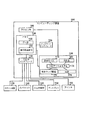
図11は、本開示の1つ以上の実施形態による、治療計画ごとの咬合調整構造物の為のシステムを示す。図11に示されたシステムは、幾つかの構成要素が結合されたコンピューティング装置1144を含む。コンピューティング装置1144は、プロセッサ1146及びメモリ1148を含む。メモリは、本明細書に記載のデータ1150及び実行可能命令1152をはじめとする様々なタイプの情報を含んでよい。
FIG. 11 illustrates a system for an occlusal adjustment structure per treatment plan, according to one or more embodiments of the present disclosure. The system shown in FIG. 11 includes a
メモリ及び/又はプロセッサは、実施形態によっては、コンピューティング装置1144の内部にあっても外部にあってもよい。従って、図11の実施形態において示されるように、システムはネットワークインタフェース1154を含んでよい。そのようなインタフェースは、ネットワーク接続された別のコンピューティング装置での処理を可能にしてよく、或いは、そのような装置は、本明細書において提供される様々な実施形態とともに使用される、患者に関する情報または実行可能命令を取得する為に使用されてよい。
The memory and / or processor may be internal or external to
図11の実施形態において示されるように、システムは、1つ以上の入力及び/又は出力インタフェース1156を含んでよい。そのようなインタフェースは、コンピューティング装置に1つ以上の入力装置又は出力装置を接続する為に使用されてよい。
As shown in the embodiment of FIG. 11, the system may include one or more input and / or
例えば、図11に示される実施形態では、システムは、スキャン装置1158、カメラドック1160、入力装置1162(例えば、キーボード、マウス等)、ディスプレイ装置1164(例えば、モニタ)、及びプリンタ1166との接続性を有する。プロセッサ1146は、ディスプレイ装置1164にデジタルモデル1174の視覚的な表示を提供するように構成されることができる(例えば、プロセッサ1146上で動作してディスプレイ装置1164で見えるGUI)。入出力インタフェース1156は、(例えば、患者の上顎及び患者の下顎に対応する)デジタルモデル1174を表す、データ記憶装置(例えば、メモリ1148)に記憶可能なデータを受けてよい。
For example, in the embodiment shown in FIG. 11, the system is connectable with a
実施形態によっては、スキャン装置1158は、患者の上顎の物理モールド及び患者の下顎の物理モールドをスキャンするように構成されてよい。1つ以上の実施形態では、スキャン装置1158は、患者の上顎及び/又は下顎を直接(口腔内で)スキャンするように構成されてよい。
In some embodiments, the
カメラドック1160は、デジタルカメラや印刷写真スキャナなどの撮像装置(例えば、2D撮像装置)からの入力を受けることが可能である。撮像装置からの入力は、データ記憶装置1148に記憶されてよい。
The
そのような接続性は、様々なタイプの情報の中でも特に、デジタルモデル1174の情報または命令の入力及び/又は出力(例えば、キーボードからの入力)を可能にしてよい。幾つかの実施形態は、1つ以上のネットワークにある様々なコンピューティング装置に分散してよいが、図11に示されているようなシステムは、本明細書で説明された情報の取り込み、計算、及び/又は分析を可能にすることに有用であってよい。 Such connectivity may allow, among other types of information, input and / or output (eg, input from a keyboard) of digital model 1174 information or instructions. Although some embodiments may be distributed to various computing devices in one or more networks, a system such as that shown in FIG. 11 may capture and calculate the information described herein. And / or may be useful to allow analysis.
プロセッサ1146は、データ記憶装置1148と関連して、データ及び/又はアプリケーションモジュール1168に関連付けられてよい。プロセッサ1146は、データ記憶装置1148と関連して、幾つかのアプリケーションモジュールを、治療計画ごとの咬合調整構造物に提供する為に、データを記憶及び/又は利用したり、且つ/又は、命令を実行したりしてよい。
そのようなデータとして、(例えば、第1の顎、第2の顎、幾つかの器具等を含む)本明細書に記載のデジタルモデル1174があってよい。そのようなアプリケーションモジュールとして、調整モジュール1170、力計算モジュール1172、咬合調整構造物配置モジュール1176、及び/又は治療計画モジュール1178があってよい。
As such data, there may be a digital model 1174 as described herein (including, for example, a first jaw, a second jaw, several appliances, etc.). As such application modules, there may be an
咬合調整構造物配置モジュール1176は、治療計画の第1の段階において、幾つかの咬合調整構造物を、顎のデジタルモデル1174の対応する数のデジタル歯(例えば、前歯)の上に配置するように構成されてよい。配置モジュール1176は、力計算モジュール1172によってモデリングされた力の結果(例えば、治療計画の第1の段階に従って、対応する数のデジタル歯を第1の距離だけ再配置する為に使用される力)を取り入れるように構成されてよい。
The occlusal adjustment
調整モジュール1170は、治療計画の第1の段階から第2の段階にかけての顎のデジタルモデル1174の変更に従って、治療計画の第2の段階において、幾つかの咬合調整構造物の、顎のデジタルモデル1174の対応する数のデジタル歯の上での位置を調整するように構成されてよい。調整モジュール1170は、幾つかのデジタル咬合調整構造物の位置を、幾つかのデジタル咬合調整構造物の、顎のデジタルモデルの対応する数のデジタル歯の上での形状(例えば、大きさ、幾つかの角度等)及び/又は取付場所を変更することによって、調整するように構成されてよい。調整モジュール1170は、治療計画の第1の段階において、顎のデジタルモデル1174の上に形成される器具のうちの対応する器具が、力計算モジュール1172によってモデリングされた力に対応する逆の力を、ユーザの顎の幾つかの臼歯に分散させるように、顎のデジタルモデル1174の形状を調整するように構成されてよい。調整モジュール1170は、力計算モジュール1172によってモデリングされた力の結果(例えば、治療計画の第2の段階に従って、対応する数のデジタル歯を第2の距離だけ再配置する為に使用される力)を取り入れるように構成されてよい。
The
力計算モジュール1172は、治療計画の第1の段階の間に器具のうちの対応する器具をユーザが装着することによって幾つかの咬合調整構造物にかかる本来の力をモデリングするように構成されてよい。治療計画モジュール1178は、(例えば、他のアプリケーションモジュール1168の動作に少なくとも部分的に基づいて)治療計画を作成したり、編集したり、削除したり、改訂したり、他の方法で修正したりするように構成されてよい。
The
デジタルモデル1174は、幾つかのデジタル咬合調整構造物の形状を継承し、顎にかぶせられる器具を形成する為の、顎に対応する、治療計画の第1及び第2の段階における物理型を製作する為に、(例えば、ネットワークインタフェース1154を介して)与えられてよい。 The digital model 1174 inherits the shape of several digital occlusal adjustment structures and produces physical versions in the first and second stages of the treatment plan, corresponding to the jaws, to form a device that can be placed on the jaws (E.g., via the network interface 1154).
本明細書において特定の実施形態を例示及び説明してきたが、当業者であれば理解されるように、同じ手法を達成すべく計算された任意の構成が、示された特定の実施形態に取って代わってよい。本開示は、本開示の各種実施形態のあらゆる翻案及び変形を包含するものとする。 While specific embodiments have been illustrated and described herein, it will be appreciated by those skilled in the art that any configuration calculated to achieve the same approach can be used in the particular embodiments shown. It may be replaced. This disclosure is intended to cover all adaptations and variations of various embodiments of the present disclosure.
当然のことながら、「a」、「an」、「one or more(1つ以上の)」、「a number of(幾つかの)」、又は「at least one(少なくとも1つの)」という語句の使用は全て、あるアイテムが1つ以上存在することを意味するものと解釈されたい。更に、当然のことながら、上述の説明は、限定ではなく例示として行われている。上述の実施形態と、本明細書では具体的に説明されていない他の実施形態との組み合わせについては、当業者であれば、上述の説明を精査することにより明らかになるであろう。 It will be appreciated that the words "a", "an", "one or more", "a number of", or "at least one" All uses should be interpreted to mean that one or more items are present. Furthermore, it should be understood that the above description is given by way of illustration, not limitation. Combinations of the above-described embodiments with other embodiments not specifically described herein will be apparent to those of ordinary skill in the art upon reviewing the above description.
当然のことながら、ある要素が別の要素に対して「上にある(on)」、「接続されている(connected to)」、又は「結合されている(coupled with)」ものとして参照された場合、その要素は、その別の要素に対して直接上にあるか、接続されているか、結合されていてよく、或いは、介在する要素が存在してもよい。これに対し、ある要素が別の要素に対して「直接上にある(directly on)」、「直接接続されている(directly connected to)」、又は「直接結合されている(directly coupled with)」ものとして参照された場合、介在する要素又は層は存在しない。本明細書では、「及び/又は(and/or)」という語句は、関連付けられて列挙されたアイテムのうちの2つ以上のアイテムのあらゆる組み合わせを包含する。 It will be appreciated that an element is referred to as being "on", "connected to" or "coupled with" another element In that case, the element may be directly over, connected to or coupled to the other element, or intervening elements may be present. In contrast, an element is "directly on", "directly connected to" or "directly coupled with" another element. When referred to as being, there are no intervening elements or layers. As used herein, the phrase "and / or" includes any and all combinations of two or more of the associated listed items.
当然のことながら、本明細書では、様々な要素を示す為に「第1の(first)」、「第2の(second)」等の語句が使用されてよいが、これらの要素は、これらの語句によって限定されるべきではない。これらの語句は、ある要素を別の要素と区別する為に使用されるのみである。従って、本開示の教示から逸脱しない限り、第1の要素が第2の要素と呼ばれることがあってよい。 It will be appreciated that, as used herein, the terms "first", "second" etc. may be used to indicate various elements, but these elements It should not be limited by the word These terms are only used to distinguish one element from another. Thus, without departing from the teachings of the present disclosure, the first element may be referred to as the second element.
本開示の各種実施形態の範囲は、上述の構造物及び方法が用いられる他の任意の応用を包含する。従って、本開示の各種実施形態の範囲は、添付の特許請求の範囲が包含しうるあらゆる等価物とともに、添付の特許請求の範囲に準拠して決定されるべきである。 The scope of the various embodiments of the present disclosure includes any other applications in which the structures and methods described above are used. Accordingly, the scope of the various embodiments of the present disclosure should be determined in accordance with the appended claims, along with any equivalents that may be included within the appended claims.
上述の「発明を実施するための形態」では、本開示を簡潔にする為に、様々な特徴を単一の実施形態の形にまとめた。本開示の方法は、本開示の実施形態が、特許請求の範囲の各項において明示的に記載されているものより多くの特徴を必要とするという意図を反映するものとして解釈されるべきではない。 In the foregoing Detailed Description, various features are grouped together in a single embodiment for the purpose of streamlining the disclosure. The methods of the present disclosure should not be construed as reflecting the intention that the embodiments of the present disclosure require more features than explicitly stated in the claims. .
むしろ、後述の特許請求の範囲によって反映されるように、発明の対象は、開示された1つの実施形態の全ての特徴より少ない特徴にある。従って、後述の特許請求の範囲は、これによって「発明を実施するための形態」に組み込まれており、特許請求の範囲の各項は、独立した実施形態として自立している。
Rather, as the following claims reflect, inventive subject matter lies in less than all features of a single disclosed embodiment. Thus, the following claims are hereby incorporated into the Detailed Description, and each claim section is self-supporting as an independent embodiment.
Claims (9)
前記第1のシェルと同じ材料で形成され、前記第1のシェルから延び、前記第1の器具が前記第1の顎の上に配置された状態で、第2の顎の歯と当接するように設計された、第1の数の咬合調整構造物であって、前記治療計画の第1の段階に固有である第1の形状及び位置を有しており、前記第1の数の咬合調整構造物と関連する歯を圧下するように構成されている、前記第1の数の咬合調整構造物と、
前記第1の顎の歯を受けるように設計された複数のキャビティを中に有する第2のシェルを備える、前記一連の器具のうちの第2の器具と、
前記第2のシェルと同じ材料で形成され、前記第2のシェルから延び、前記第2の器具が前記第1の顎の上に配置された状態で、前記第2の顎の歯と当接するように設計された、第2の数の咬合調整構造物であって、前記治療計画の第2の段階であって前記第1の段階の後の前記第2の段階に固有である、前記第1の形状及び位置と異なる第2の形状及び位置を有しており、前記第2の数の咬合調整構造物と関連する歯を圧下するように構成されている、前記第2の数の咬合調整構造物と、を備え、
前記第2の数の咬合調整構造物の位置は、前記第1の数の咬合調整構造物の位置に比べて、咬合面に近い、
システム。 The first of a series of instruments designed to progressively implement a treatment plan, the first having a plurality of cavities therein designed to receive the teeth of a first jaw. Said first device comprising a shell;
Formed of the same material as the first shell, extending from the first shell, and in abutment with the teeth of the second jaw, with the first device being disposed on the first jaw A first number of occlusal adjustment structures designed to have a first shape and position specific to the first stage of the treatment plan, the first number of occlusal adjustments Said first number of occlusal adjustment structures configured to depress teeth associated with the structure;
A second device of the series of devices comprising a second shell having a plurality of cavities therein designed to receive the teeth of the first jaw;
Formed of the same material as the second shell, extending from the second shell, and in abutment with the teeth of the second jaw, with the second device being disposed on the first jaw A second number of bite-adjusting structures designed for the second stage, said second stage being specific to said second stage after said first stage, said second stage of said treatment planning; The second number of occlusions having a second shape and location different from the shape and location of one and configured to depress a tooth associated with the second number of occlusion regulating structures And an adjustment structure ,
The position of the second number of occlusal adjustment structures is closer to the occlusal surface than the position of the first number of occlusal adjustment structures,
system.
前記第1の顎の歯を受けるように設計された複数のキャビティを中に有する第6のシェルを備える第6の器具と、
前記第6のシェルと同じ材料で形成され、前記第6のシェルから延びる、第6の数の咬合調整構造物であって、前記治療計画の第6の段階に固有である第6の形状及び位置を有する、前記第6の数の咬合調整構造物と、
前記第2の顎の歯を受けるように設計された複数のキャビティを中に有する第7のシェルを備える、第7の器具と、
前記第7のシェルと同じ材料で形成され、前記第7のシェルから延び、前記第6の数の咬合調整構造物と相互に作用するように設計された、第7の数の咬合調整構造物であって、前記治療計画の前記第6の段階に固有である、第7の形状及び位置を有する、前記第7の数の咬合調整構造物と、を含む、
請求項1に記載のシステム。 The series of devices
A sixth device comprising a sixth shell having therein a plurality of cavities designed to receive the teeth of the first jaw;
A sixth number of occlusal adjustment structures formed of the same material as the sixth shell and extending from the sixth shell, the sixth shape being unique to the sixth stage of the treatment plan and The sixth number of occlusal adjustment structures having a position;
A seventh device comprising a seventh shell having therein a plurality of cavities designed to receive the teeth of the second jaw;
A seventh number of occlusal adjustment structures formed of the same material as the seventh shell, extending from the seventh shell and designed to interact with the sixth number of occlusal adjustment structures And said seventh number of bite-adjusting structures having a seventh shape and position, specific to said sixth stage of said treatment plan;
The system of claim 1.
Applications Claiming Priority (3)
| Application Number | Priority Date | Filing Date | Title |
|---|---|---|---|
| US14/186,799 | 2014-02-21 | ||
| US14/186,799 US10299894B2 (en) | 2014-02-21 | 2014-02-21 | Treatment plan specific bite adjustment structures |
| PCT/IB2015/000214 WO2015125005A2 (en) | 2014-02-21 | 2015-02-20 | Treatment plan specific bite adjustment structures |
Related Child Applications (1)
| Application Number | Title | Priority Date | Filing Date |
|---|---|---|---|
| JP2018241983A Division JP7038038B2 (en) | 2014-02-21 | 2018-12-26 | Occlusion adjustment structure for each treatment plan |
Publications (2)
| Publication Number | Publication Date |
|---|---|
| JP2017506123A JP2017506123A (en) | 2017-03-02 |
| JP6502953B2 true JP6502953B2 (en) | 2019-04-17 |
Family
ID=52633322
Family Applications (3)
| Application Number | Title | Priority Date | Filing Date |
|---|---|---|---|
| JP2016553476A Active JP6502953B2 (en) | 2014-02-21 | 2015-02-20 | Occlusal adjustment structure for each treatment plan |
| JP2018241983A Active JP7038038B2 (en) | 2014-02-21 | 2018-12-26 | Occlusion adjustment structure for each treatment plan |
| JP2020162158A Active JP7100684B2 (en) | 2014-02-21 | 2020-09-28 | Occlusion adjustment structure for each treatment plan |
Family Applications After (2)
| Application Number | Title | Priority Date | Filing Date |
|---|---|---|---|
| JP2018241983A Active JP7038038B2 (en) | 2014-02-21 | 2018-12-26 | Occlusion adjustment structure for each treatment plan |
| JP2020162158A Active JP7100684B2 (en) | 2014-02-21 | 2020-09-28 | Occlusion adjustment structure for each treatment plan |
Country Status (9)
| Country | Link |
|---|---|
| US (7) | US10299894B2 (en) |
| EP (2) | EP3107480B1 (en) |
| JP (3) | JP6502953B2 (en) |
| KR (4) | KR102247260B1 (en) |
| CN (3) | CN106456286B (en) |
| AU (4) | AU2015220534B2 (en) |
| CA (1) | CA2940174C (en) |
| ES (1) | ES2738331T3 (en) |
| WO (1) | WO2015125005A2 (en) |
Families Citing this family (141)
| Publication number | Priority date | Publication date | Assignee | Title |
|---|---|---|---|---|
| US11026768B2 (en) | 1998-10-08 | 2021-06-08 | Align Technology, Inc. | Dental appliance reinforcement |
| US9492245B2 (en) | 2004-02-27 | 2016-11-15 | Align Technology, Inc. | Method and system for providing dynamic orthodontic assessment and treatment profiles |
| US9326831B2 (en) | 2006-10-20 | 2016-05-03 | Align Technology, Inc. | System and method for positioning three-dimensional brackets on teeth |
| US7878805B2 (en) | 2007-05-25 | 2011-02-01 | Align Technology, Inc. | Tabbed dental appliance |
| US8738394B2 (en) | 2007-11-08 | 2014-05-27 | Eric E. Kuo | Clinical data file |
| US8899977B2 (en) | 2008-01-29 | 2014-12-02 | Align Technology, Inc. | Orthodontic repositioning appliances having improved geometry, methods and systems |
| US9492243B2 (en) | 2008-05-23 | 2016-11-15 | Align Technology, Inc. | Dental implant positioning |
| US8092215B2 (en) | 2008-05-23 | 2012-01-10 | Align Technology, Inc. | Smile designer |
| US9119691B2 (en) | 2008-05-23 | 2015-09-01 | Align Technology, Inc. | Orthodontic tooth movement device, systems and methods |
| US8172569B2 (en) | 2008-06-12 | 2012-05-08 | Align Technology, Inc. | Dental appliance |
| US8152518B2 (en) | 2008-10-08 | 2012-04-10 | Align Technology, Inc. | Dental positioning appliance having metallic portion |
| US8292617B2 (en) | 2009-03-19 | 2012-10-23 | Align Technology, Inc. | Dental wire attachment |
| US8765031B2 (en) | 2009-08-13 | 2014-07-01 | Align Technology, Inc. | Method of forming a dental appliance |
| US9211166B2 (en) | 2010-04-30 | 2015-12-15 | Align Technology, Inc. | Individualized orthodontic treatment index |
| US9241774B2 (en) | 2010-04-30 | 2016-01-26 | Align Technology, Inc. | Patterned dental positioning appliance |
| US20110269092A1 (en) | 2010-04-30 | 2011-11-03 | Align Technology, Inc. | Reinforced aligner hooks |
| US9403238B2 (en) | 2011-09-21 | 2016-08-02 | Align Technology, Inc. | Laser cutting |
| US9375300B2 (en) | 2012-02-02 | 2016-06-28 | Align Technology, Inc. | Identifying forces on a tooth |
| US9220580B2 (en) | 2012-03-01 | 2015-12-29 | Align Technology, Inc. | Determining a dental treatment difficulty |
| US9655691B2 (en) | 2012-05-14 | 2017-05-23 | Align Technology, Inc. | Multilayer dental appliances and related methods and systems |
| US9414897B2 (en) | 2012-05-22 | 2016-08-16 | Align Technology, Inc. | Adjustment of tooth position in a virtual dental model |
| US10555792B2 (en) * | 2014-01-31 | 2020-02-11 | Align Technology, Inc. | Direct fabrication of orthodontic appliances with elastics |
| JP6422502B2 (en) | 2014-01-31 | 2018-11-14 | アライン テクノロジー, インコーポレイテッド | Orthodontic appliance having an elastic body |
| US11642198B2 (en) | 2014-06-20 | 2023-05-09 | Align Technology, Inc. | Elastic-coated orthodontic appliance |
| US10299894B2 (en) * | 2014-02-21 | 2019-05-28 | Align Technology, Inc. | Treatment plan specific bite adjustment structures |
| US9844424B2 (en) | 2014-02-21 | 2017-12-19 | Align Technology, Inc. | Dental appliance with repositioning jaw elements |
| US10537406B2 (en) * | 2014-02-21 | 2020-01-21 | Align Technology, Inc. | Dental appliance with repositioning jaw elements |
| CN115068134A (en) | 2014-03-21 | 2022-09-20 | 阿莱恩技术有限公司 | Segmented orthodontic appliances with elastics |
| EP3157458B1 (en) | 2014-06-20 | 2021-05-19 | Align Technology, Inc. | Aligners with elastic layer |
| US10772506B2 (en) | 2014-07-07 | 2020-09-15 | Align Technology, Inc. | Apparatus for dental confocal imaging |
| US9675430B2 (en) | 2014-08-15 | 2017-06-13 | Align Technology, Inc. | Confocal imaging apparatus with curved focal surface |
| US9700385B2 (en) | 2014-08-22 | 2017-07-11 | Alitn Technology, Inc. | Attachment structure |
| US9610141B2 (en) | 2014-09-19 | 2017-04-04 | Align Technology, Inc. | Arch expanding appliance |
| US10449016B2 (en) | 2014-09-19 | 2019-10-22 | Align Technology, Inc. | Arch adjustment appliance |
| US9744001B2 (en) | 2014-11-13 | 2017-08-29 | Align Technology, Inc. | Dental appliance with cavity for an unerupted or erupting tooth |
| US10517701B2 (en) | 2015-01-13 | 2019-12-31 | Align Technology, Inc. | Mandibular advancement and retraction via bone anchoring devices |
| US10588776B2 (en) | 2015-01-13 | 2020-03-17 | Align Technology, Inc. | Systems, methods, and devices for applying distributed forces for mandibular advancement |
| US10537463B2 (en) | 2015-01-13 | 2020-01-21 | Align Technology, Inc. | Systems and methods for positioning a patient's mandible in response to sleep apnea status |
| US10504386B2 (en) | 2015-01-27 | 2019-12-10 | Align Technology, Inc. | Training method and system for oral-cavity-imaging-and-modeling equipment |
| EP3261578B1 (en) | 2015-02-23 | 2023-08-16 | Align Technology, Inc. | System and method to manufacture aligner by modifying tooth position |
| US10179035B2 (en) * | 2015-03-04 | 2019-01-15 | Real 3D Polymers Group Llc | Direct 3D-printed orthodontic aligners with torque, rotation, and full control anchors |
| US11484390B2 (en) * | 2015-03-04 | 2022-11-01 | Real 3D Polymers Llc | Direct 3D-printed orthodontic aligners with torque, rotation, and full control anchors |
| US11963842B2 (en) | 2015-07-07 | 2024-04-23 | Align Technology, Inc. | Appliances for intraoral delivery of agents |
| US11944514B2 (en) | 2015-07-07 | 2024-04-02 | Align Technology, Inc. | Methods for fabricating dental appliances with integrally formed components |
| US10492888B2 (en) | 2015-07-07 | 2019-12-03 | Align Technology, Inc. | Dental materials using thermoset polymers |
| US10248883B2 (en) | 2015-08-20 | 2019-04-02 | Align Technology, Inc. | Photograph-based assessment of dental treatments and procedures |
| US10357336B2 (en) | 2015-10-07 | 2019-07-23 | uLab Systems, Inc. | Systems and methods for fabricating dental appliances or shells |
| US10631953B2 (en) | 2015-10-07 | 2020-04-28 | uLab Systems, Inc. | Three-dimensional printed dental appliances using support structures |
| US11583365B2 (en) | 2015-10-07 | 2023-02-21 | uLab Systems, Inc. | System and methods for tooth movement as a flock |
| US10624717B2 (en) | 2015-10-07 | 2020-04-21 | Ulab Systems Inc. | Tooth modeling system |
| US10335250B2 (en) | 2015-10-07 | 2019-07-02 | uLab Systems, Inc. | Three-dimensional printed dental appliances using lattices |
| US10548690B2 (en) | 2015-10-07 | 2020-02-04 | uLab Systems, Inc. | Orthodontic planning systems |
| US11554000B2 (en) | 2015-11-12 | 2023-01-17 | Align Technology, Inc. | Dental attachment formation structure |
| US11931222B2 (en) | 2015-11-12 | 2024-03-19 | Align Technology, Inc. | Dental attachment formation structures |
| US11596502B2 (en) | 2015-12-09 | 2023-03-07 | Align Technology, Inc. | Dental attachment placement structure |
| US11103330B2 (en) | 2015-12-09 | 2021-08-31 | Align Technology, Inc. | Dental attachment placement structure |
| KR101676205B1 (en) * | 2015-12-31 | 2016-11-15 | 이민정 | Clear aligner device producting method |
| WO2017218947A1 (en) | 2016-06-17 | 2017-12-21 | Align Technology, Inc. | Intraoral appliances with sensing |
| EP3988048B1 (en) | 2016-06-17 | 2024-01-17 | Align Technology, Inc. | Orthodontic appliance performance monitor |
| US9820828B1 (en) * | 2016-07-18 | 2017-11-21 | Ibtesam M. Y. Mustafa | Removable veneers for teeth |
| EP4252698A3 (en) | 2016-07-27 | 2023-12-06 | Align Technology, Inc. | Intraoral scanner with dental diagnostics capabilities |
| US10507087B2 (en) | 2016-07-27 | 2019-12-17 | Align Technology, Inc. | Methods and apparatuses for forming a three-dimensional volumetric model of a subject's teeth |
| US10357342B2 (en) | 2016-09-21 | 2019-07-23 | uLab Systems, Inc. | Digital dental examination and documentation |
| US10952821B2 (en) | 2016-09-21 | 2021-03-23 | uLab Systems, Inc. | Combined orthodontic movement of teeth with temporomandibular joint therapy |
| CN109789000B (en) | 2016-09-21 | 2022-07-19 | 友莱博系统公司 | Orthodontic movement of teeth in combination with airway developmental therapy |
| US20180078342A1 (en) * | 2016-09-21 | 2018-03-22 | William Graham Gardner | Dental Appliance For Use as an Aligner and as a Tool to Reduce Temporomandibular Dysfunction |
| EP4295748A3 (en) | 2016-11-04 | 2024-03-27 | Align Technology, Inc. | Methods and apparatuses for dental images |
| US11376101B2 (en) | 2016-12-02 | 2022-07-05 | Align Technology, Inc. | Force control, stop mechanism, regulating structure of removable arch adjustment appliance |
| US10993783B2 (en) | 2016-12-02 | 2021-05-04 | Align Technology, Inc. | Methods and apparatuses for customizing a rapid palatal expander |
| EP3547952B1 (en) | 2016-12-02 | 2020-11-04 | Align Technology, Inc. | Palatal expander |
| US11026831B2 (en) | 2016-12-02 | 2021-06-08 | Align Technology, Inc. | Dental appliance features for speech enhancement |
| US10548700B2 (en) | 2016-12-16 | 2020-02-04 | Align Technology, Inc. | Dental appliance etch template |
| US10456043B2 (en) | 2017-01-12 | 2019-10-29 | Align Technology, Inc. | Compact confocal dental scanning apparatus |
| WO2018135673A1 (en) * | 2017-01-17 | 2018-07-26 | 이민정 | Method for manufacturing clear aligners |
| CN110366396A (en) * | 2017-01-25 | 2019-10-22 | 登士柏希罗纳有限公司 | Photocuring dental system |
| US10779718B2 (en) | 2017-02-13 | 2020-09-22 | Align Technology, Inc. | Cheek retractor and mobile device holder |
| CN110891518B (en) * | 2017-03-02 | 2021-10-22 | 巴伊材料公司 | Dental appliances with different properties |
| US12090020B2 (en) | 2017-03-27 | 2024-09-17 | Align Technology, Inc. | Apparatuses and methods assisting in dental therapies |
| US10613515B2 (en) | 2017-03-31 | 2020-04-07 | Align Technology, Inc. | Orthodontic appliances including at least partially un-erupted teeth and method of forming them |
| US11045283B2 (en) | 2017-06-09 | 2021-06-29 | Align Technology, Inc. | Palatal expander with skeletal anchorage devices |
| WO2018232299A1 (en) | 2017-06-16 | 2018-12-20 | Align Technology, Inc. | Automatic detection of tooth type and eruption status |
| US10636522B2 (en) | 2017-06-21 | 2020-04-28 | SmileDirectClub LLC | Arrangements for intraoral scanning |
| US11337778B2 (en) | 2017-06-21 | 2022-05-24 | Sdc U.S. Smilepay Spv | Distributed system for fabricating dental aligners |
| US20180368941A1 (en) * | 2017-06-21 | 2018-12-27 | SmileDirectClub LLC | Dental impression kit and methods therefor |
| US20180368954A1 (en) | 2017-06-21 | 2018-12-27 | SmileDirectClub LLC | Dental impression kit and methods therefor |
| US11253409B2 (en) | 2017-06-21 | 2022-02-22 | Sdc U.S. Smilepay Spv | Systems and methods for mobile dentition scanning |
| US10639134B2 (en) | 2017-06-26 | 2020-05-05 | Align Technology, Inc. | Biosensor performance indicator for intraoral appliances |
| CN115006018A (en) * | 2017-06-30 | 2022-09-06 | 阿莱恩技术有限公司 | Computer-implemented method and system for designing and/or manufacturing an orthodontic appliance for treating or preventing temporomandibular joint dysfunction |
| CA3146509A1 (en) * | 2017-07-03 | 2019-01-10 | Clearcorrect Operating, Llc | Systems and methods for designing, and improving retention of, orthodontic aligners |
| US10885521B2 (en) | 2017-07-17 | 2021-01-05 | Align Technology, Inc. | Method and apparatuses for interactive ordering of dental aligners |
| CN114903623A (en) | 2017-07-21 | 2022-08-16 | 阿莱恩技术有限公司 | Jaw profile anchoring |
| WO2019023461A1 (en) | 2017-07-27 | 2019-01-31 | Align Technology, Inc. | Tooth shading, transparency and glazing |
| US10517482B2 (en) | 2017-07-27 | 2019-12-31 | Align Technology, Inc. | Optical coherence tomography for orthodontic aligners |
| US11331166B2 (en) * | 2017-07-27 | 2022-05-17 | Align Technology, Inc. | Surgical stabilizer aligner |
| US20190046297A1 (en) * | 2017-08-11 | 2019-02-14 | Align Technology, Inc. | Devices and systems for creation of attachments for use with dental appliances and changeable shaped attachments |
| WO2019035979A1 (en) | 2017-08-15 | 2019-02-21 | Align Technology, Inc. | Buccal corridor assessment and computation |
| CN110996837B (en) * | 2017-08-17 | 2022-07-26 | 阿莱恩技术有限公司 | System, method and apparatus for correcting malocclusions |
| US11123156B2 (en) | 2017-08-17 | 2021-09-21 | Align Technology, Inc. | Dental appliance compliance monitoring |
| US10813720B2 (en) | 2017-10-05 | 2020-10-27 | Align Technology, Inc. | Interproximal reduction templates |
| WO2019084326A1 (en) * | 2017-10-27 | 2019-05-02 | Align Technology, Inc. | Alternative bite adjustment structures |
| US11576752B2 (en) | 2017-10-31 | 2023-02-14 | Align Technology, Inc. | Dental appliance having selective occlusal loading and controlled intercuspation |
| WO2019089782A1 (en) | 2017-11-01 | 2019-05-09 | Align Technology, Inc. | Systems and methods for correcting malocclusions of teeth |
| CN115252177A (en) | 2017-11-01 | 2022-11-01 | 阿莱恩技术有限公司 | Automated therapy planning |
| WO2019100022A1 (en) | 2017-11-17 | 2019-05-23 | Align Technology, Inc. | Orthodontic retainers |
| CN114948315B (en) | 2017-11-30 | 2024-08-27 | 阿莱恩技术有限公司 | Sensor for monitoring oral appliance |
| WO2019118876A1 (en) | 2017-12-15 | 2019-06-20 | Align Technology, Inc. | Closed loop adaptive orthodontic treatment methods and apparatuses |
| US10980613B2 (en) | 2017-12-29 | 2021-04-20 | Align Technology, Inc. | Augmented reality enhancements for dental practitioners |
| JP7427595B2 (en) | 2018-01-26 | 2024-02-05 | アライン テクノロジー, インコーポレイテッド | Intraoral scanning and tracking for diagnosis |
| US11317993B2 (en) * | 2018-02-09 | 2022-05-03 | Spartan Orthodontics Inc. | Orthodontic device for overbite correction |
| US11937991B2 (en) | 2018-03-27 | 2024-03-26 | Align Technology, Inc. | Dental attachment placement structure |
| US11564777B2 (en) | 2018-04-11 | 2023-01-31 | Align Technology, Inc. | Releasable palatal expanders |
| AU2019262641A1 (en) | 2018-05-04 | 2020-12-03 | Align Technology, Inc. | Curable composition for use in a high temperature lithography-based photopolymerization process and method of producing crosslinked polymers therefrom |
| US11504214B2 (en) | 2018-05-11 | 2022-11-22 | Align Technology, Inc. | Devices, systems, and computer-implemented methods for dental attachment templates |
| US11701203B2 (en) | 2018-06-29 | 2023-07-18 | Align Technology, Inc. | Dental appliance hook placement and visualization |
| US12064313B2 (en) | 2021-02-16 | 2024-08-20 | Ormco Corporation | Orthodontic appliance with bite structures and methods of making same |
| CN112703100B (en) | 2018-09-14 | 2023-06-06 | 阿莱恩技术有限公司 | Hybrid 3D printing with photo-curable material |
| US11123157B2 (en) * | 2018-10-05 | 2021-09-21 | Ross Aronson | Universal attachment for an orthodontic aligner |
| CA3122991C (en) | 2018-12-11 | 2022-10-11 | Gary B. Wiele | An assembly for treatment providing non-invasive controlled positioning and movement of a patient's jaw |
| US11771527B2 (en) | 2019-02-20 | 2023-10-03 | Sdc U.S. Smilepay Spv | Limited wear aligner and treatment methods |
| US20200297245A1 (en) * | 2019-03-21 | 2020-09-24 | Bruce Willard Hultgren | Motion adjustment prediction system |
| US12064315B2 (en) | 2019-04-30 | 2024-08-20 | uLab Systems, Inc. | Indirect bonding tray system |
| CN110251248A (en) * | 2019-05-31 | 2019-09-20 | 上海交通大学医学院附属第九人民医院 | A kind of dental appliance with occlusion guiding |
| US11602414B2 (en) | 2019-06-11 | 2023-03-14 | Align Technology, Inc. | Aligner material, cleanliness, and quality detection via aligner case |
| CN114641257A (en) | 2019-09-16 | 2022-06-17 | 阿莱恩技术有限公司 | Durable decorative marking carrier |
| CN211633659U (en) * | 2019-10-10 | 2020-10-09 | 无锡时代天使生物科技有限公司 | Shell-shaped tooth orthodontic appliance |
| EP4065037A1 (en) | 2019-12-09 | 2022-10-05 | Align Technology, Inc. | Occlusal block design for lateral locking |
| US11723748B2 (en) | 2019-12-23 | 2023-08-15 | Align Technology, Inc. | 2D-to-3D tooth reconstruction, optimization, and positioning frameworks using a differentiable renderer |
| US11622836B2 (en) | 2019-12-31 | 2023-04-11 | Align Technology, Inc. | Aligner stage analysis to obtain mechanical interactions of aligners and teeth for treatment planning |
| WO2021178363A1 (en) | 2020-03-02 | 2021-09-10 | Align Technology, Inc. | Low viscosity photo-curable resins for the direct fabrication of orthodontic appliances |
| CN115485310A (en) | 2020-03-13 | 2022-12-16 | 阿莱恩技术有限公司 | Weak covalent crosslinking for toughness enhancement in thermosets |
| US20220023006A1 (en) * | 2020-07-22 | 2022-01-27 | Clearcorrect Operating, Llc | Mandibular repositioning appliances and methods of manufacturing the same |
| WO2022027071A1 (en) | 2020-07-31 | 2022-02-03 | Align Technology, Inc. | Direct fabrication of mixed metal and polymer orthodontic devices |
| US11661468B2 (en) | 2020-08-27 | 2023-05-30 | Align Technology, Inc. | Additive manufacturing using variable temperature-controlled resins |
| US11957479B2 (en) | 2020-09-03 | 2024-04-16 | Steven A. Swidler | Systems, apparatuses, and methods for diagnosis and treatment of temporomandibular disorders (TMD) |
| US11969311B2 (en) | 2020-12-14 | 2024-04-30 | Align Technology, Inc. | Replacement attachment system |
| US20220218438A1 (en) * | 2021-01-14 | 2022-07-14 | Orthosnap Corp. | Creating three-dimensional (3d) animation |
| WO2022226416A1 (en) | 2021-04-23 | 2022-10-27 | Align Technology, Inc. | Monomeric and polymeric compositions and methods of producing and using the same |
| US11992383B2 (en) | 2021-06-23 | 2024-05-28 | uLab Systems, Inc. | System for force measurement upon orthodontic appliances |
| US11939287B2 (en) | 2021-06-24 | 2024-03-26 | Align Technology, Inc. | Recovery of monomeric and oligomeric building blocks from polymeric materials |
| WO2023217254A1 (en) * | 2022-05-13 | 2023-11-16 | 正雅齿科科技(上海)有限公司 | Dental instrument, dental instrument kit, and design methods and preparation methods therefor |
| USD1035006S1 (en) | 2022-09-12 | 2024-07-09 | Align Technology, Inc. | Dental aligner storage case |
Family Cites Families (222)
| Publication number | Priority date | Publication date | Assignee | Title |
|---|---|---|---|---|
| US2467432A (en) | 1943-07-23 | 1949-04-19 | Harold D Kesling | Method of making orthodontic appliances and of positioning teeth |
| US3379193A (en) * | 1965-10-11 | 1968-04-23 | Richard P. Monaghan | Method of forming and using teeth covers |
| US3407500A (en) | 1966-05-06 | 1968-10-29 | Peter C. Kesling | Tooth positioner |
| CH467972A (en) | 1966-12-29 | 1969-01-31 | Sulzer Ag | Steam generator with panel-like heating surfaces arranged above the combustion chamber |
| US3478742A (en) * | 1967-10-23 | 1969-11-18 | Edward H Bohlmann | Orthodontic multipurpose repositioner and oral habit conditioner |
| US3660900A (en) | 1969-11-10 | 1972-05-09 | Lawrence F Andrews | Method and apparatus for improved orthodontic bracket and arch wire technique |
| US3600808A (en) | 1970-01-22 | 1971-08-24 | James Jackson Reeve | Anterior root-torquing auxiliary wire |
| US3860803A (en) | 1970-08-24 | 1975-01-14 | Diecomp Inc | Automatic method and apparatus for fabricating progressive dies |
| US3683502A (en) | 1970-09-14 | 1972-08-15 | Melvin Wallshein | Orthodontic systems |
| US3738005A (en) | 1972-03-22 | 1973-06-12 | M Cohen | Method and apparatus for applying orthodontic brackets and the like |
| US3916526A (en) | 1973-05-10 | 1975-11-04 | Fred Frank Schudy | Method and apparatus for orthodontic treatment |
| US3922786A (en) | 1974-01-30 | 1975-12-02 | Joseph L Lavin | Method and apparatus for forming and fitting orthodontic appliances |
| US3983628A (en) | 1975-01-24 | 1976-10-05 | Raul Acevedo | Dental articulator, new bite registration guide, and diagnostic procedure associated with stereodont orthodontic study model |
| US3950851A (en) | 1975-03-05 | 1976-04-20 | Bergersen Earl Olaf | Orthodontic positioner and method for improving retention of tooth alignment therewith |
| US4014096A (en) | 1975-03-25 | 1977-03-29 | Dellinger Eugene L | Method and apparatus for orthodontic treatment |
| JPS5358191A (en) | 1976-11-05 | 1978-05-25 | Osamu Yoshii | Method of producing dental correction treating instrument using silicon resin material |
| US4348178A (en) | 1977-01-03 | 1982-09-07 | Kurz Craven H | Vibrational orthodontic appliance |
| US4195046A (en) | 1978-05-04 | 1980-03-25 | Kesling Peter C | Method for molding air holes into a tooth positioning and retaining appliance |
| US4324547A (en) | 1978-09-16 | 1982-04-13 | Vishay Intertechnology, Inc. | Dentistry technique |
| US4253828A (en) | 1979-04-09 | 1981-03-03 | Coles Donna C | Orthodontic appliance |
| DE2936847A1 (en) | 1979-09-12 | 1981-03-19 | Paul Dr. 6054 Rodgau Heitlinger | METHOD FOR PRODUCING DENTAL SPARE AND DEVICE FOR IMPLEMENTING THE METHOD |
| US4330273A (en) * | 1980-07-21 | 1982-05-18 | Kesling Peter C | Orthodontic appliance and method for producing occlusion |
| US4575805A (en) | 1980-12-24 | 1986-03-11 | Moermann Werner H | Method and apparatus for the fabrication of custom-shaped implants |
| US4419992A (en) | 1981-02-12 | 1983-12-13 | Chorbajian Peter M | Occlusal splints and the method of manufacturing the same |
| US4557692A (en) * | 1981-02-12 | 1985-12-10 | Chorbajian Peter M | Occlusal splints and the method of manufacturing the same |
| DE3203937C2 (en) | 1982-02-05 | 1985-10-03 | Luc Dr. 4150 Krefeld Barrut | Method and device for machine restoration or correction of at least one tooth or for machine preparation of at least one tooth for a fixed prosthetic restoration and for machine production of the fixed prosthetic restoration |
| FR2525103B1 (en) | 1982-04-14 | 1985-09-27 | Duret Francois | IMPRESSION TAKING DEVICE BY OPTICAL MEANS, PARTICULARLY FOR THE AUTOMATIC PRODUCTION OF PROSTHESES |
| US4509918A (en) | 1982-04-22 | 1985-04-09 | Clark William J | Apparatus for the orthodontic treatment of teeth |
| US4663720A (en) | 1984-02-21 | 1987-05-05 | Francois Duret | Method of and apparatus for making a prosthesis, especially a dental prosthesis |
| US4500294A (en) | 1983-10-03 | 1985-02-19 | Epic International Corporation | Method and device for detecting dental cavities |
| US4526540A (en) | 1983-12-19 | 1985-07-02 | Dellinger Eugene L | Orthodontic apparatus and method for treating malocclusion |
| DE3415006A1 (en) | 1984-04-19 | 1985-11-07 | Helge Dr. 8000 München Fischer-Brandies | DENTAL PROCESS AND DEVICE FOR BENDING AND TURNING A WIRE PIECE |
| US4798534A (en) | 1984-08-03 | 1989-01-17 | Great Lakes Orthodontic Laboratories Inc. | Method of making a dental appliance |
| US4575330A (en) | 1984-08-08 | 1986-03-11 | Uvp, Inc. | Apparatus for production of three-dimensional objects by stereolithography |
| US4609349A (en) | 1984-09-24 | 1986-09-02 | Cain Steve B | Active removable orthodontic appliance and method of straightening teeth |
| US4591341A (en) | 1984-10-03 | 1986-05-27 | Andrews Lawrence F | Orthodontic positioner and method of manufacturing same |
| US4664626A (en) | 1985-03-19 | 1987-05-12 | Kesling Peter C | System for automatically preventing overtipping and/or overuprighting in the begg technique |
| US4763791A (en) | 1985-06-06 | 1988-08-16 | Excel Dental Studios, Inc. | Dental impression supply kit |
| GB2176402B (en) | 1985-06-20 | 1989-04-19 | Craig Med Prod Ltd | Wound management appliance for use on the human skin |
| US4936862A (en) | 1986-05-30 | 1990-06-26 | Walker Peter S | Method of designing and manufacturing a human joint prosthesis |
| CH672722A5 (en) | 1986-06-24 | 1989-12-29 | Marco Brandestini | |
| US4877398A (en) | 1987-04-16 | 1989-10-31 | Tp Orthodontics, Inc. | Bracket for permitting tipping and limiting uprighting |
| CA1284040C (en) | 1986-06-26 | 1991-05-14 | Peter C. Kesling | Edgewise bracket to provide both free crown tipping and a predetermineddegree of root uprighting |
| US4676747A (en) | 1986-08-06 | 1987-06-30 | Tp Orthodontics, Inc. | Torquing auxiliary |
| US4983334A (en) | 1986-08-28 | 1991-01-08 | Loren S. Adell | Method of making an orthodontic appliance |
| US4755139A (en) | 1987-01-29 | 1988-07-05 | Great Lakes Orthodontics, Ltd. | Orthodontic anchor appliance and method for teeth positioning and method of constructing the appliance |
| US4850864A (en) | 1987-03-30 | 1989-07-25 | Diamond Michael K | Bracket placing instrument |
| US4850865A (en) | 1987-04-30 | 1989-07-25 | Napolitano John R | Orthodontic method and apparatus |
| US4856991A (en) * | 1987-05-05 | 1989-08-15 | Great Lakes Orthodontics, Ltd. | Orthodontic finishing positioner and method of construction |
| US5186623A (en) | 1987-05-05 | 1993-02-16 | Great Lakes Orthodontics, Ltd. | Orthodontic finishing positioner and method of construction |
| US4836778A (en) | 1987-05-26 | 1989-06-06 | Vexcel Corporation | Mandibular motion monitoring system |
| DE3723555C2 (en) | 1987-07-16 | 1994-08-11 | Steinbichler Hans | Process for the production of dentures |
| NL8702391A (en) | 1987-10-07 | 1989-05-01 | Elephant Edelmetaal Bv | METHOD FOR MANUFACTURING A DENTAL CROWN FOR A TEETH PREPARATION USING A CAD-CAM SYSTEM |
| US4793803A (en) | 1987-10-08 | 1988-12-27 | Martz Martin G | Removable tooth positioning appliance and method |
| US4880380A (en) | 1987-10-13 | 1989-11-14 | Martz Martin G | Orthodonture appliance which may be manually installed and removed by the patient |
| US4773853A (en) * | 1987-11-09 | 1988-09-27 | Leon Kussick | Oral orthopedic appliance |
| US5130064A (en) | 1988-04-18 | 1992-07-14 | 3D Systems, Inc. | Method of making a three dimensional object by stereolithography |
| US4941826A (en) | 1988-06-09 | 1990-07-17 | William Loran | Apparatus for indirect dental machining |
| US5100316A (en) | 1988-09-26 | 1992-03-31 | Wildman Alexander J | Orthodontic archwire shaping method |
| US5055039A (en) * | 1988-10-06 | 1991-10-08 | Great Lakes Orthodontics, Ltd. | Orthodontic positioner and methods of making and using same |
| US4935635A (en) | 1988-12-09 | 1990-06-19 | Harra Dale G O | System for measuring objects in three dimensions |
| IL88842A (en) | 1988-12-30 | 1990-07-26 | Shafir Aaron | Apparatus and method for digitizing the contour of a surface particularly useful for preparing a dental crown |
| US5011405A (en) | 1989-01-24 | 1991-04-30 | Dolphin Imaging Systems | Method for determining orthodontic bracket placement |
| AU4950290A (en) | 1989-01-24 | 1990-08-24 | Dolphin Imaging Systems Inc. | Method and apparatus for generating cephalometric images |
| US4889238A (en) | 1989-04-03 | 1989-12-26 | The Procter & Gamble Company | Medicament package for increasing compliance with complex therapeutic regimens |
| US4975052A (en) | 1989-04-18 | 1990-12-04 | William Spencer | Orthodontic appliance for reducing tooth rotation |
| US4915630A (en) * | 1989-05-15 | 1990-04-10 | Honig Gordon C | Dental splint |
| US5121333A (en) | 1989-06-09 | 1992-06-09 | Regents Of The University Of Minnesota | Method and apparatus for manipulating computer-based representations of objects of complex and unique geometry |
| US5128870A (en) | 1989-06-09 | 1992-07-07 | Regents Of The University Of Minnesota | Automated high-precision fabrication of objects of complex and unique geometry |
| US5257203A (en) | 1989-06-09 | 1993-10-26 | Regents Of The University Of Minnesota | Method and apparatus for manipulating computer-based representations of objects of complex and unique geometry |
| US5027281A (en) | 1989-06-09 | 1991-06-25 | Regents Of The University Of Minnesota | Method and apparatus for scanning and recording of coordinates describing three dimensional objects of complex and unique geometry |
| US5184306A (en) | 1989-06-09 | 1993-02-02 | Regents Of The University Of Minnesota | Automated high-precision fabrication of objects of complex and unique geometry |
| JPH039712U (en) | 1989-06-20 | 1991-01-30 | ||
| FR2652256A1 (en) | 1989-09-26 | 1991-03-29 | Jourda Gerard | DEVICE FOR ESTABLISHING THE TRACE OF A REMOVABLE PARTIAL DENTAL PLATE. |
| US5395238A (en) | 1990-01-19 | 1995-03-07 | Ormco Corporation | Method of forming orthodontic brace |
| US5533895A (en) | 1990-01-19 | 1996-07-09 | Ormco Corporation | Orthodontic appliance and group standardized brackets therefor and methods of making, assembling and using appliance to straighten teeth |
| US5431562A (en) | 1990-01-19 | 1995-07-11 | Ormco Corporation | Method and apparatus for designing and forming a custom orthodontic appliance and for the straightening of teeth therewith |
| US5368478A (en) | 1990-01-19 | 1994-11-29 | Ormco Corporation | Method for forming jigs for custom placement of orthodontic appliances on teeth |
| US5474448A (en) | 1990-01-19 | 1995-12-12 | Ormco Corporation | Low profile orthodontic appliance |
| US5454717A (en) | 1990-01-19 | 1995-10-03 | Ormco Corporation | Custom orthodontic brackets and bracket forming method and apparatus |
| US5139419A (en) | 1990-01-19 | 1992-08-18 | Ormco Corporation | Method of forming an orthodontic brace |
| US5447432A (en) | 1990-01-19 | 1995-09-05 | Ormco Corporation | Custom orthodontic archwire forming method and apparatus |
| US5440326A (en) | 1990-03-21 | 1995-08-08 | Gyration, Inc. | Gyroscopic pointer |
| US5562448A (en) | 1990-04-10 | 1996-10-08 | Mushabac; David R. | Method for facilitating dental diagnosis and treatment |
| JPH0428359A (en) | 1990-05-24 | 1992-01-30 | Mitsubishi Petrochem Co Ltd | Manufacture of mouthpiece for teeth set correction |
| US5452219A (en) | 1990-06-11 | 1995-09-19 | Dentsply Research & Development Corp. | Method of making a tooth mold |
| US5340309A (en) | 1990-09-06 | 1994-08-23 | Robertson James G | Apparatus and method for recording jaw motion |
| SE468198B (en) | 1990-12-12 | 1992-11-23 | Nobelpharma Ab | PROCEDURE AND DEVICE FOR MANUFACTURE OF INDIVIDUALLY DESIGNED THREE-DIMENSIONAL BODIES USEFUL AS TENDERS, PROTESTES, ETC |
| US5131844A (en) | 1991-04-08 | 1992-07-21 | Foster-Miller, Inc. | Contact digitizer, particularly for dental applications |
| US5131843A (en) | 1991-05-06 | 1992-07-21 | Ormco Corporation | Orthodontic archwire |
| US5145364A (en) | 1991-05-15 | 1992-09-08 | M-B Orthodontics, Inc. | Removable orthodontic appliance |
| US5176517A (en) | 1991-10-24 | 1993-01-05 | Tru-Tain, Inc. | Dental undercut application device and method of use |
| SE469158B (en) | 1991-11-01 | 1993-05-24 | Nobelpharma Ab | DENTAL SENSOR DEVICE INTENDED TO BE USED IN CONNECTION WITH CONTROL OF A WORKING EQUIPMENT |
| US5328362A (en) | 1992-03-11 | 1994-07-12 | Watson Sherman L | Soft resilient interocclusal dental appliance, method of forming same and composition for same |
| US5273429A (en) | 1992-04-03 | 1993-12-28 | Foster-Miller, Inc. | Method and apparatus for modeling a dental prosthesis |
| US5384862A (en) | 1992-05-29 | 1995-01-24 | Cimpiter Corporation | Radiographic image evaluation apparatus and method |
| FR2693096B1 (en) | 1992-07-06 | 1994-09-23 | Deshayes Marie Josephe | Process for modeling the cranial and facial morphology from an x-ray of the skull. |
| WO1994010935A1 (en) | 1992-11-09 | 1994-05-26 | Ormco Corporation | Custom orthodontic appliance forming method and apparatus |
| US5456600A (en) | 1992-11-09 | 1995-10-10 | Ormco Corporation | Coordinated orthodontic archwires and method of making same |
| US5542842A (en) | 1992-11-09 | 1996-08-06 | Ormco Corporation | Bracket placement jig assembly and method of placing orthodontic brackets on teeth therewith |
| US5528735A (en) | 1993-03-23 | 1996-06-18 | Silicon Graphics Inc. | Method and apparatus for displaying data within a three-dimensional information landscape |
| SE501333C2 (en) | 1993-05-27 | 1995-01-16 | Sandvik Ab | Method for making ceramic tooth restorations |
| CN1054737C (en) | 1993-07-12 | 2000-07-26 | 欧索-泰公司 | A multi-racial preformed orthodontic treatment appliance |
| SE501411C2 (en) | 1993-07-12 | 1995-02-06 | Nobelpharma Ab | Method and apparatus for three-dimensional body useful in the human body |
| SE501410C2 (en) | 1993-07-12 | 1995-02-06 | Nobelpharma Ab | Method and apparatus in connection with the manufacture of tooth, bridge, etc. |
| NL9301308A (en) | 1993-07-26 | 1995-02-16 | Willem Frederick Van Nifterick | Method of securing a dental prosthesis to implants in a patient's jawbone and using means thereof. |
| US5382164A (en) | 1993-07-27 | 1995-01-17 | Stern; Sylvan S. | Method for making dental restorations and the dental restoration made thereby |
| US5427117A (en) | 1993-09-29 | 1995-06-27 | Thornton; W. Keith | Apparatus for prevention of snoring and improved breathing during sleep |
| US5435902A (en) | 1993-10-01 | 1995-07-25 | Andre, Sr.; Larry E. | Method of incremental object fabrication |
| US5338198A (en) | 1993-11-22 | 1994-08-16 | Dacim Laboratory Inc. | Dental modeling simulator |
| SE502427C2 (en) | 1994-02-18 | 1995-10-16 | Nobelpharma Ab | Method and device utilizing articulator and computer equipment |
| US5678567A (en) | 1994-03-25 | 1997-10-21 | Thornton; W. Keith | Apparatus for adjusting a dental device |
| US5621648A (en) | 1994-08-02 | 1997-04-15 | Crump; Craig D. | Apparatus and method for creating three-dimensional modeling data from an object |
| US5880961A (en) | 1994-08-02 | 1999-03-09 | Crump; Craig D. | Appararus and method for creating three-dimensional modeling data from an object |
| SE503498C2 (en) | 1994-10-04 | 1996-06-24 | Nobelpharma Ab | Method and device for a product intended to be part of the human body and a scanning device for a model for the product |
| US5549476A (en) | 1995-03-27 | 1996-08-27 | Stern; Sylvan S. | Method for making dental restorations and the dental restoration made thereby |
| JP3672966B2 (en) | 1995-04-14 | 2005-07-20 | 株式会社ユニスン | Method and apparatus for creating dental prediction model |
| US5645421A (en) | 1995-04-28 | 1997-07-08 | Great Lakes Orthodontics Ltd. | Orthodontic appliance debonder |
| US5885073A (en) * | 1995-06-09 | 1999-03-23 | Kussick Orthodontic Systems, Llc | Orthopedic incline appliance and method |
| US5683244A (en) | 1995-07-10 | 1997-11-04 | Truax; Lloyd H. | Dental appliance to correct malocclusion |
| US5655653A (en) | 1995-07-11 | 1997-08-12 | Minnesota Mining And Manufacturing Company | Pouch for orthodontic appliance |
| JP3727660B2 (en) | 1995-07-21 | 2005-12-14 | カデント・リミテッド | Method for obtaining a three-dimensional tooth image |
| US5742700A (en) | 1995-08-10 | 1998-04-21 | Logicon, Inc. | Quantitative dental caries detection system and method |
| US6382975B1 (en) | 1997-02-26 | 2002-05-07 | Technique D'usinage Sinlab Inc. | Manufacturing a dental implant drill guide and a dental implant superstructure |
| US5725376A (en) | 1996-02-27 | 1998-03-10 | Poirier; Michel | Methods for manufacturing a dental implant drill guide and a dental implant superstructure |
| US5692894A (en) | 1996-04-08 | 1997-12-02 | Raintree Essix, Inc. | Thermoformed plastic dental retainer and method of construction |
| US5799100A (en) | 1996-06-03 | 1998-08-25 | University Of South Florida | Computer-assisted method and apparatus for analysis of x-ray images using wavelet transforms |
| US5823778A (en) | 1996-06-14 | 1998-10-20 | The United States Of America As Represented By The Secretary Of The Air Force | Imaging method for fabricating dental devices |
| US5725378A (en) | 1996-08-16 | 1998-03-10 | Wang; Hong-Chi | Artificial tooth assembly |
| JPH1075963A (en) | 1996-09-06 | 1998-03-24 | Nikon Corp | Method for designing dental prosthetic appliance model and medium recording program for executing the method |
| AUPO280996A0 (en) | 1996-10-04 | 1996-10-31 | Dentech Investments Pty Ltd | Creation and utilization of 3D teeth models |
| JP2824424B2 (en) | 1996-11-07 | 1998-11-11 | 株式会社エフ・エーラボ | 3D machining method |
| US6217334B1 (en) | 1997-01-28 | 2001-04-17 | Iris Development Corporation | Dental scanning method and apparatus |
| US5795150A (en) * | 1997-03-03 | 1998-08-18 | Boyd; James P. | Intraoral semi-custom discluder device and method |
| SE509141C2 (en) | 1997-04-10 | 1998-12-07 | Nobel Biocare Ab | Arrangements and systems for dental product production and information provision |
| US5957686A (en) * | 1997-04-29 | 1999-09-28 | Anthony; Wayne L. | Incisor block |
| US5848115A (en) | 1997-05-02 | 1998-12-08 | General Electric Company | Computed tomography metrology |
| US5879158A (en) | 1997-05-20 | 1999-03-09 | Doyle; Walter A. | Orthodontic bracketing system and method therefor |
| US5866058A (en) | 1997-05-29 | 1999-02-02 | Stratasys Inc. | Method for rapid prototyping of solid models |
| US5975893A (en) | 1997-06-20 | 1999-11-02 | Align Technology, Inc. | Method and system for incrementally moving teeth |
| US6309215B1 (en) | 1997-06-20 | 2001-10-30 | Align Technology Inc. | Attachment devices and method for a dental applicance |
| AU744385B2 (en) | 1997-06-20 | 2002-02-21 | Align Technology, Inc. | Method and system for incrementally moving teeth |
| US6183248B1 (en) | 1998-11-30 | 2001-02-06 | Muhammad Chishti | System and method for releasing tooth positioning appliances |
| US6705863B2 (en) | 1997-06-20 | 2004-03-16 | Align Technology, Inc. | Attachment devices and methods for a dental appliance |
| US6450807B1 (en) * | 1997-06-20 | 2002-09-17 | Align Technology, Inc. | System and method for positioning teeth |
| US6152731A (en) | 1997-09-22 | 2000-11-28 | 3M Innovative Properties Company | Methods for use in dental articulation |
| US5934288A (en) | 1998-04-23 | 1999-08-10 | General Electric Company | Method and apparatus for displaying 3D ultrasound data using three modes of operation |
| AUPP450598A0 (en) | 1998-07-06 | 1998-07-30 | Palmisano, Richard George | A mandibular advancement device |
| US5971754A (en) | 1998-07-30 | 1999-10-26 | Sondhi; Anoop | Indirect bonding method and adhesive for orthodontic treatment |
| US5964587A (en) | 1998-09-16 | 1999-10-12 | Sato; Mikio | Bite control point and a method to form a projection on tooth surface |
| ES2579776T3 (en) * | 1998-10-08 | 2016-08-16 | Align Technology, Inc. | AUTOMATED DEVELOPMENT BY COMPUTER OF AN ORTHODONIC TREATMENT PLAN AND APPARATUS |
| US20020192617A1 (en) * | 2000-04-25 | 2002-12-19 | Align Technology, Inc. | Embedded features and methods of a dental appliance |
| US6572372B1 (en) * | 2000-04-25 | 2003-06-03 | Align Technology, Inc. | Embedded features and methods of a dental appliance |
| US6123544A (en) | 1998-12-18 | 2000-09-26 | 3M Innovative Properties Company | Method and apparatus for precise bond placement of orthodontic appliances |
| US6190165B1 (en) | 1999-03-23 | 2001-02-20 | Ormco Corporation | Plastic orthodontic appliance having mechanical bonding base and method of making same |
| US6315553B1 (en) | 1999-11-30 | 2001-11-13 | Orametrix, Inc. | Method and apparatus for site treatment of an orthodontic patient |
| US6350120B1 (en) | 1999-11-30 | 2002-02-26 | Orametrix, Inc. | Method and apparatus for designing an orthodontic apparatus to provide tooth movement |
| US6633789B1 (en) | 2000-02-17 | 2003-10-14 | Align Technology, Inc. | Effiicient data representation of teeth model |
| US6463344B1 (en) | 2000-02-17 | 2002-10-08 | Align Technology, Inc. | Efficient data representation of teeth model |
| US6364659B1 (en) * | 2000-02-23 | 2002-04-02 | 3M Innovative Properties Company | Orthodontic bite opener |
| US6368106B1 (en) | 2000-03-22 | 2002-04-09 | William J. Clark | Mandibular advancer and method of installing the same |
| US6530375B1 (en) * | 2000-03-22 | 2003-03-11 | Charles R. Cieslik, Jr. | Appliance to correct tempromandibular joint syndrome and methods of making and use |
| ES2594884T3 (en) | 2000-04-25 | 2016-12-23 | Align Technology, Inc. | Systems for repositioning teeth with devices that have variable stiffness |
| US6524101B1 (en) | 2000-04-25 | 2003-02-25 | Align Technology, Inc. | System and methods for varying elastic modulus appliances |
| US6402707B1 (en) | 2000-06-28 | 2002-06-11 | Denupp Corporation Bvi | Method and system for real time intra-orally acquiring and registering three-dimensional measurements and images of intra-oral objects and features |
| US6464495B1 (en) * | 2000-08-29 | 2002-10-15 | Orthoarm, Inc. | Gnathological bite opener |
| US6482298B1 (en) | 2000-09-27 | 2002-11-19 | International Business Machines Corporation | Apparatus for electroplating alloy films |
| US6783360B2 (en) * | 2000-12-13 | 2004-08-31 | Align Technology, Inc. | Systems and methods for positioning teeth |
| US7771195B2 (en) * | 2001-10-29 | 2010-08-10 | Align Technology, Inc. | Polar attachment devices and method for a dental appliance |
| US20030116164A1 (en) * | 2001-12-14 | 2003-06-26 | Boyd James P. | Intraoral discluder device and method for preventing migraine, tension headache, and temporomandibular disorders |
| US6776614B2 (en) | 2002-02-13 | 2004-08-17 | Lingualcare, Inc. | Modular system for customized orthodontic appliances |
| US20030207224A1 (en) | 2002-05-01 | 2003-11-06 | Lotte Brian Walter | Patient specific bite positioner |
| YU103904A (en) | 2002-05-30 | 2006-05-25 | Ortho-Tain Inc. | A dental appliance having a duplicated tooth area and/or a predicated tooth area and a method for correcting the position of the teeth of a patient |
| US7104790B2 (en) | 2002-05-31 | 2006-09-12 | Cronauer Edward A | Orthodontic appliance with embedded wire for moving teeth and method |
| US7963765B2 (en) * | 2002-09-20 | 2011-06-21 | Ortho-Tain, Inc | System of dental appliances having various sizes and types and a method for treating malocclusions of patients of various ages without adjustments or appointments |
| US7159591B2 (en) | 2003-05-06 | 2007-01-09 | Leon Kussick | Kussick mandibular advancement appliance |
| AU2003903900A0 (en) * | 2003-07-25 | 2003-08-07 | Myohealth Pty Ltd | Improved occlusal splint |
| US7077646B2 (en) | 2003-08-29 | 2006-07-18 | Jack Keith Hilliard | Automated method for producing improved orthodontic aligners |
| US7354270B2 (en) | 2003-12-22 | 2008-04-08 | Align Technology, Inc. | Surgical dental appliance |
| US7293987B2 (en) * | 2004-04-30 | 2007-11-13 | Norbert Abels | Adjustable bite ramps for deep bite correction and kits incorporating bite ramps |
| US20050244781A1 (en) * | 2004-04-29 | 2005-11-03 | Norbert Abels | Orthodontic treatment method for concurrent correction of multiple conditions |
| US7226287B2 (en) * | 2004-04-30 | 2007-06-05 | Ultradent Products, Inc. | Kits comprising a plurality of bite ramps having different angles for orthodontic treatment |
| CN2712303Y (en) * | 2004-05-20 | 2005-07-27 | 李昌浩 | Movable type teeth occlusion device |
| US7654267B2 (en) | 2004-06-29 | 2010-02-02 | Nti-Tss, Inc. | Intraoral discluder and method for relieving migraine and tension headaches and temporomandibular disorders |
| US20060078840A1 (en) | 2004-10-08 | 2006-04-13 | Robson Farrand C | Dental orthotic for management of impaired oral functions |
| AU2005305194A1 (en) * | 2004-11-10 | 2006-05-18 | Ortho-Tain, Inc. | Upper and lower single preformed and/or customized appliance |
| US7972134B2 (en) * | 2005-04-01 | 2011-07-05 | 3M Innovative Properties Company | Response surfaces for orthodontic treatment planning |
| US7730891B2 (en) * | 2005-10-07 | 2010-06-08 | Lamberg Steven B | Intraoral mandibular advancement device for treatment of sleep disorders |
| US20080102414A1 (en) * | 2006-10-27 | 2008-05-01 | Norbert Abels | Posterior bite ramps, kits, and methods of use to correct class ii and/or class iii malocclusions |
| GB0703384D0 (en) | 2007-02-21 | 2007-03-28 | Ortho Pro Teknica Ltd | Orthodontic appliances |
| EP2124805A4 (en) * | 2007-03-07 | 2014-03-26 | Darenton Holdings Pty Ltd | Apparatus and methods for correction of orthodontic malocclusions |
| US8099268B2 (en) | 2007-05-25 | 2012-01-17 | Align Technology, Inc. | Tooth modeling |
| US20090087808A1 (en) * | 2007-09-28 | 2009-04-02 | Reika Ortho Technologies, Inc. | Methods And Systems For Moving Teeth |
| US8439672B2 (en) * | 2008-01-29 | 2013-05-14 | Align Technology, Inc. | Method and system for optimizing dental aligner geometry |
| US8257079B1 (en) * | 2008-03-27 | 2012-09-04 | Plowman Paul E | Orthodontic appliance |
| US8297286B2 (en) * | 2008-10-20 | 2012-10-30 | Rampup, Llc | Physical rehabilitation and training aid: method of using musculoskeletal repositioning device |
| US8061358B2 (en) | 2008-10-20 | 2011-11-22 | Rampup, Llc | Birthing aid: method of using musculoskeletal repositioning device |
| JP6058889B2 (en) * | 2008-11-20 | 2017-01-11 | アライン テクノロジー, インコーポレイテッド | Orthodontic system and method including parametric attachment |
| US20100129763A1 (en) | 2008-11-24 | 2010-05-27 | Align Technology, Inc. | Sequential sports guard |
| US8573224B2 (en) * | 2009-10-16 | 2013-11-05 | Airway Technologies, Llc | Custom-molded oral appliance and method of forming |
| US8272866B2 (en) * | 2009-11-27 | 2012-09-25 | James Jiwen Chun | Removable orthodontic appliance |
| WO2012140021A2 (en) | 2011-04-10 | 2012-10-18 | 3Shape A/S | Modeling and manufacturing orthodontic appliances |
| US10383704B2 (en) * | 2011-10-12 | 2019-08-20 | Ormco Corporation | Direct manufacture of orthodontic aligner appliance |
| US9314320B2 (en) | 2011-10-19 | 2016-04-19 | Tmj Services Llc | Device for mitigation of temporomandibular joint disorder |
| DE102012005323B4 (en) | 2012-03-19 | 2015-05-13 | Gernot Heine | Jaw-related correction device and method of making the device |
| CN102715957A (en) * | 2012-05-10 | 2012-10-10 | 苏州艾若克医疗科技有限公司 | Novel oral cavity orthodontic appliance |
| US9730768B2 (en) * | 2013-02-22 | 2017-08-15 | Kelly Lucas | CAD-CAM AGP splint—a method of automatically producing or reproducing a customized AGP (anterior guidance package) equipped splint for a patient with/without a severe malocclusion via one time dentist visit |
| US10080680B2 (en) * | 2013-07-01 | 2018-09-25 | R. Joseph Magness | Dental appliance for treatment of bruxism |
| CN103340690A (en) | 2013-07-17 | 2013-10-09 | 上海正雅齿科科技有限公司 | Methods for manufacturing and using invisible orthodontic devices |
| CN105451681B (en) | 2013-08-09 | 2018-09-18 | 庆熙大学校产学协力团 | It is removably installed in the dental appliance of tooth |
| US20150132707A1 (en) * | 2013-09-11 | 2015-05-14 | Ormco Corporation | Braces to aligner transition in orthodontic treatment |
| US20150216626A1 (en) * | 2014-02-03 | 2015-08-06 | N. Daniel Ranjbar | Method For Placement Of Dental Attachments For Use With Dental Aligners |
| US9844424B2 (en) | 2014-02-21 | 2017-12-19 | Align Technology, Inc. | Dental appliance with repositioning jaw elements |
| US10299894B2 (en) * | 2014-02-21 | 2019-05-28 | Align Technology, Inc. | Treatment plan specific bite adjustment structures |
| US10537406B2 (en) * | 2014-02-21 | 2020-01-21 | Align Technology, Inc. | Dental appliance with repositioning jaw elements |
| US9943991B2 (en) * | 2014-05-21 | 2018-04-17 | Align Technology, Inc. | Mold with separable features |
| US9943386B2 (en) * | 2014-05-21 | 2018-04-17 | Align Technology, Inc. | Mold with weakened areas |
| US10588776B2 (en) * | 2015-01-13 | 2020-03-17 | Align Technology, Inc. | Systems, methods, and devices for applying distributed forces for mandibular advancement |
| US11571278B2 (en) * | 2015-07-07 | 2023-02-07 | Align Technology, Inc. | Systems, apparatuses and methods for dental appliances with integrally formed features |
| US11576752B2 (en) * | 2017-10-31 | 2023-02-14 | Align Technology, Inc. | Dental appliance having selective occlusal loading and controlled intercuspation |
| CN208725922U (en) | 2018-03-16 | 2019-04-12 | 无锡时代天使医疗器械科技有限公司 | Shelly-shaped dental appliance and its shell-like body |
| EP3905984B1 (en) * | 2019-01-03 | 2024-02-21 | Align Technology, Inc. | Automatic aligner design with robust parametric optimization method |
-
2014
- 2014-02-21 US US14/186,799 patent/US10299894B2/en active Active
-
2015
- 2015-02-20 CN CN201580021176.8A patent/CN106456286B/en active Active
- 2015-02-20 KR KR1020197038216A patent/KR102247260B1/en active IP Right Grant
- 2015-02-20 CN CN202210792296.XA patent/CN115153911A/en active Pending
- 2015-02-20 WO PCT/IB2015/000214 patent/WO2015125005A2/en active Application Filing
- 2015-02-20 CN CN202010526175.1A patent/CN111772835B/en active Active
- 2015-02-20 KR KR1020167025918A patent/KR102061249B1/en active IP Right Grant
- 2015-02-20 ES ES15708880T patent/ES2738331T3/en active Active
- 2015-02-20 AU AU2015220534A patent/AU2015220534B2/en active Active
- 2015-02-20 JP JP2016553476A patent/JP6502953B2/en active Active
- 2015-02-20 CA CA2940174A patent/CA2940174C/en active Active
- 2015-02-20 EP EP15708880.8A patent/EP3107480B1/en active Active
- 2015-02-20 EP EP19175891.1A patent/EP3572032A1/en active Pending
- 2015-02-20 KR KR1020217012592A patent/KR102347111B1/en active IP Right Grant
- 2015-02-20 KR KR1020217043322A patent/KR102483683B1/en active IP Right Grant
-
2018
- 2018-12-26 JP JP2018241983A patent/JP7038038B2/en active Active
-
2019
- 2019-03-11 US US16/299,011 patent/US11723753B2/en active Active
- 2019-04-10 AU AU2019202513A patent/AU2019202513B2/en active Active
- 2019-05-29 US US16/425,829 patent/US11141243B2/en active Active
- 2019-05-29 US US16/425,845 patent/US10980616B2/en active Active
- 2019-12-04 US US16/703,613 patent/US12064316B2/en active Active
-
2020
- 2020-09-28 JP JP2020162158A patent/JP7100684B2/en active Active
- 2020-11-23 AU AU2020277085A patent/AU2020277085B2/en active Active
-
2021
- 2021-10-05 US US17/494,627 patent/US11490996B2/en active Active
-
2022
- 2022-01-07 AU AU2022200069A patent/AU2022200069B2/en active Active
-
2024
- 2024-05-20 US US18/669,345 patent/US20240307154A1/en active Pending
Also Published As
Similar Documents
| Publication | Publication Date | Title |
|---|---|---|
| JP7100684B2 (en) | Occlusion adjustment structure for each treatment plan | |
| CN111565668B (en) | Substitute occlusion adjusting structure |
Legal Events
| Date | Code | Title | Description |
|---|---|---|---|
| A521 | Request for written amendment filed |
Free format text: JAPANESE INTERMEDIATE CODE: A523 Effective date: 20170301 |
|
| A621 | Written request for application examination |
Free format text: JAPANESE INTERMEDIATE CODE: A621 Effective date: 20170731 |
|
| A131 | Notification of reasons for refusal |
Free format text: JAPANESE INTERMEDIATE CODE: A131 Effective date: 20180417 |
|
| A977 | Report on retrieval |
Free format text: JAPANESE INTERMEDIATE CODE: A971007 Effective date: 20180418 |
|
| A521 | Request for written amendment filed |
Free format text: JAPANESE INTERMEDIATE CODE: A523 Effective date: 20180712 |
|
| A02 | Decision of refusal |
Free format text: JAPANESE INTERMEDIATE CODE: A02 Effective date: 20180828 |
|
| A521 | Request for written amendment filed |
Free format text: JAPANESE INTERMEDIATE CODE: A523 Effective date: 20181226 |
|
| C60 | Trial request (containing other claim documents, opposition documents) |
Free format text: JAPANESE INTERMEDIATE CODE: C60 Effective date: 20181226 |
|
| A911 | Transfer to examiner for re-examination before appeal (zenchi) |
Free format text: JAPANESE INTERMEDIATE CODE: A911 Effective date: 20190107 |
|
| C21 | Notice of transfer of a case for reconsideration by examiners before appeal proceedings |
Free format text: JAPANESE INTERMEDIATE CODE: C21 Effective date: 20190115 |
|
| TRDD | Decision of grant or rejection written | ||
| A01 | Written decision to grant a patent or to grant a registration (utility model) |
Free format text: JAPANESE INTERMEDIATE CODE: A01 Effective date: 20190305 |
|
| A61 | First payment of annual fees (during grant procedure) |
Free format text: JAPANESE INTERMEDIATE CODE: A61 Effective date: 20190322 |
|
| R150 | Certificate of patent or registration of utility model |
Ref document number: 6502953 Country of ref document: JP Free format text: JAPANESE INTERMEDIATE CODE: R150 |
|
| R250 | Receipt of annual fees |
Free format text: JAPANESE INTERMEDIATE CODE: R250 |
|
| R250 | Receipt of annual fees |
Free format text: JAPANESE INTERMEDIATE CODE: R250 |
|
| R250 | Receipt of annual fees |
Free format text: JAPANESE INTERMEDIATE CODE: R250 |