JP6501672B2 - Particulate matter detection system - Google Patents
Particulate matter detection system Download PDFInfo
- Publication number
- JP6501672B2 JP6501672B2 JP2015162665A JP2015162665A JP6501672B2 JP 6501672 B2 JP6501672 B2 JP 6501672B2 JP 2015162665 A JP2015162665 A JP 2015162665A JP 2015162665 A JP2015162665 A JP 2015162665A JP 6501672 B2 JP6501672 B2 JP 6501672B2
- Authority
- JP
- Japan
- Prior art keywords
- particulate matter
- deposited
- temperature
- electrode
- exhaust gas
- Prior art date
- Legal status (The legal status is an assumption and is not a legal conclusion. Google has not performed a legal analysis and makes no representation as to the accuracy of the status listed.)
- Active
Links
- 239000013618 particulate matter Substances 0.000 title claims description 137
- 238000001514 detection method Methods 0.000 title claims description 72
- 230000020169 heat generation Effects 0.000 claims description 43
- 230000008021 deposition Effects 0.000 claims description 29
- 238000005259 measurement Methods 0.000 claims description 12
- 238000010438 heat treatment Methods 0.000 claims description 7
- 238000009529 body temperature measurement Methods 0.000 claims description 6
- 238000011144 upstream manufacturing Methods 0.000 claims description 4
- 230000006698 induction Effects 0.000 claims description 3
- 230000002093 peripheral effect Effects 0.000 claims description 2
- 230000008018 melting Effects 0.000 description 14
- 238000002844 melting Methods 0.000 description 14
- 230000004927 fusion Effects 0.000 description 8
- 230000006866 deterioration Effects 0.000 description 7
- 238000002474 experimental method Methods 0.000 description 6
- 230000005476 size effect Effects 0.000 description 6
- 238000006243 chemical reaction Methods 0.000 description 5
- 230000005496 eutectics Effects 0.000 description 5
- 239000000446 fuel Substances 0.000 description 4
- 238000000034 method Methods 0.000 description 3
- 239000010705 motor oil Substances 0.000 description 3
- 230000015556 catabolic process Effects 0.000 description 2
- 239000000919 ceramic Substances 0.000 description 2
- 238000006731 degradation reaction Methods 0.000 description 2
- 239000012212 insulator Substances 0.000 description 2
- 239000000155 melt Substances 0.000 description 2
- 230000003647 oxidation Effects 0.000 description 2
- 238000007254 oxidation reaction Methods 0.000 description 2
- 230000004043 responsiveness Effects 0.000 description 2
- 229920006395 saturated elastomer Polymers 0.000 description 2
- 239000000126 substance Substances 0.000 description 2
- OKTJSMMVPCPJKN-UHFFFAOYSA-N Carbon Chemical compound [C] OKTJSMMVPCPJKN-UHFFFAOYSA-N 0.000 description 1
- 230000001133 acceleration Effects 0.000 description 1
- 238000004364 calculation method Methods 0.000 description 1
- 229910052799 carbon Inorganic materials 0.000 description 1
- 230000000052 comparative effect Effects 0.000 description 1
- 230000000694 effects Effects 0.000 description 1
- 239000010419 fine particle Substances 0.000 description 1
- 239000011810 insulating material Substances 0.000 description 1
- 239000002184 metal Substances 0.000 description 1
- 229910052751 metal Inorganic materials 0.000 description 1
- 239000002245 particle Substances 0.000 description 1
Images


Classifications
-
- F—MECHANICAL ENGINEERING; LIGHTING; HEATING; WEAPONS; BLASTING
- F01—MACHINES OR ENGINES IN GENERAL; ENGINE PLANTS IN GENERAL; STEAM ENGINES
- F01N—GAS-FLOW SILENCERS OR EXHAUST APPARATUS FOR MACHINES OR ENGINES IN GENERAL; GAS-FLOW SILENCERS OR EXHAUST APPARATUS FOR INTERNAL COMBUSTION ENGINES
- F01N3/00—Exhaust or silencing apparatus having means for purifying, rendering innocuous, or otherwise treating exhaust
- F01N3/02—Exhaust or silencing apparatus having means for purifying, rendering innocuous, or otherwise treating exhaust for cooling, or for removing solid constituents of, exhaust
- F01N3/021—Exhaust or silencing apparatus having means for purifying, rendering innocuous, or otherwise treating exhaust for cooling, or for removing solid constituents of, exhaust by means of filters
- F01N3/022—Exhaust or silencing apparatus having means for purifying, rendering innocuous, or otherwise treating exhaust for cooling, or for removing solid constituents of, exhaust by means of filters characterised by specially adapted filtering structure, e.g. honeycomb, mesh or fibrous
-
- F—MECHANICAL ENGINEERING; LIGHTING; HEATING; WEAPONS; BLASTING
- F01—MACHINES OR ENGINES IN GENERAL; ENGINE PLANTS IN GENERAL; STEAM ENGINES
- F01N—GAS-FLOW SILENCERS OR EXHAUST APPARATUS FOR MACHINES OR ENGINES IN GENERAL; GAS-FLOW SILENCERS OR EXHAUST APPARATUS FOR INTERNAL COMBUSTION ENGINES
- F01N3/00—Exhaust or silencing apparatus having means for purifying, rendering innocuous, or otherwise treating exhaust
- F01N3/02—Exhaust or silencing apparatus having means for purifying, rendering innocuous, or otherwise treating exhaust for cooling, or for removing solid constituents of, exhaust
- F01N3/021—Exhaust or silencing apparatus having means for purifying, rendering innocuous, or otherwise treating exhaust for cooling, or for removing solid constituents of, exhaust by means of filters
- F01N3/023—Exhaust or silencing apparatus having means for purifying, rendering innocuous, or otherwise treating exhaust for cooling, or for removing solid constituents of, exhaust by means of filters using means for regenerating the filters, e.g. by burning trapped particles
- F01N3/027—Exhaust or silencing apparatus having means for purifying, rendering innocuous, or otherwise treating exhaust for cooling, or for removing solid constituents of, exhaust by means of filters using means for regenerating the filters, e.g. by burning trapped particles using electric or magnetic heating means
-
- F—MECHANICAL ENGINEERING; LIGHTING; HEATING; WEAPONS; BLASTING
- F01—MACHINES OR ENGINES IN GENERAL; ENGINE PLANTS IN GENERAL; STEAM ENGINES
- F01N—GAS-FLOW SILENCERS OR EXHAUST APPARATUS FOR MACHINES OR ENGINES IN GENERAL; GAS-FLOW SILENCERS OR EXHAUST APPARATUS FOR INTERNAL COMBUSTION ENGINES
- F01N3/00—Exhaust or silencing apparatus having means for purifying, rendering innocuous, or otherwise treating exhaust
- F01N3/08—Exhaust or silencing apparatus having means for purifying, rendering innocuous, or otherwise treating exhaust for rendering innocuous
- F01N3/10—Exhaust or silencing apparatus having means for purifying, rendering innocuous, or otherwise treating exhaust for rendering innocuous by thermal or catalytic conversion of noxious components of exhaust
- F01N3/24—Exhaust or silencing apparatus having means for purifying, rendering innocuous, or otherwise treating exhaust for rendering innocuous by thermal or catalytic conversion of noxious components of exhaust characterised by constructional aspects of converting apparatus
Description
本発明は、粒子状物質検出センサと、該粒子状物質検出センサに接続した制御部とを備える粒子状物質検出システムに関する。 The present invention relates to a particulate matter detection system including a particulate matter detection sensor and a control unit connected to the particulate matter detection sensor.
排ガス中の粒子状物質(PM:Particulate Matter)の量を測定する粒子状物質検出センサと、該粒子状物質検出センサに接続した制御部とを備える粒子状物質検出システムが知られている(下記特許文献1参照)。上記粒子状物質検出センサは、排ガス中の粒子状物質が堆積する被堆積部と、該被堆積部に設けられた一対の電極と、被堆積部を加熱するヒータとを備える。被堆積部に粒子状物質が堆積すると、上記一対の電極間に電流が流れる。この電流を測定することにより、排ガスに含まれる粒子状物質の量を測定するよう構成されている。 There is known a particulate matter detection system including a particulate matter detection sensor for measuring the amount of particulate matter (PM: Particulate Matter) in exhaust gas, and a control unit connected to the particulate matter detection sensor (described below) Patent Document 1). The particulate matter detection sensor includes a portion to be deposited on which particulate matter in exhaust gas is deposited, a pair of electrodes provided on the portion to be deposited, and a heater for heating the portion to be deposited. When the particulate matter is deposited on the portion to be deposited, a current flows between the pair of electrodes. By measuring this current, the amount of particulate matter contained in the exhaust gas is measured.
制御部は、測定モードと発熱モードとを行う。制御部は、測定モードでは、上記一対の電極間に流れる電流を測定し、その測定値に基づいて、排ガス中の粒子状物質の量を算出する。また、発熱モードでは、ヒータを発熱させて、被堆積部に堆積した粒子状物質を燃焼し除去する。これにより、粒子状物質検出センサを再生するよう構成されている。 The control unit performs the measurement mode and the heat generation mode. In the measurement mode, the control unit measures the current flowing between the pair of electrodes, and calculates the amount of particulate matter in the exhaust gas based on the measured value. In the heat generation mode, the heater generates heat to burn and remove particulate matter deposited on the portion to be deposited. Thereby, the particulate matter detection sensor is configured to be regenerated.
上記粒子状物質には、いわゆるアッシュが含まれている。アッシュは、エンジンオイルに含まれている金属成分等が酸化して発生したもので、例えば、P、S、Ca等の酸化物からなる。アッシュの融点は、一般的には900℃以上であると考えられている。アッシュは絶縁体であるため、アッシュが上記電極の表面に融着すると、一対の電極間に電流が流れにくくなり、粒子状物質検出センサの性能が劣化しやすくなる。そのため、電極表面にアッシュが融着することを防止すべく、上記粒子状物質検出システムでは、発熱モードにおける被堆積部の温度を600〜900℃にしている。アッシュの融点は900℃以上であるため、被堆積部の温度を600〜900℃にすれば、アッシュは融解せず、電極の表面にアッシュが融着することを抑制できると考えられる。 The above-mentioned particulate matter contains so-called ash. Ash is generated by oxidation of metal components and the like contained in engine oil, and is made of, for example, oxides such as P, S, Ca and the like. The melting point of ash is generally considered to be 900 ° C. or higher. Since the ash is an insulator, when the ash is fused to the surface of the electrode, current does not easily flow between the pair of electrodes, and the performance of the particulate matter detection sensor tends to deteriorate. Therefore, in the above particulate matter detection system, the temperature of the portion to be deposited in the heat generation mode is set to 600 to 900 ° C. in order to prevent the fusion of ash on the electrode surface. Since the melting point of ash is 900 ° C. or higher, it is considered that if the temperature of the deposition site is 600 to 900 ° C., the ash does not melt, and fusion of the ash to the surface of the electrode can be suppressed.
しかしながら、被堆積部の温度を600〜900℃にしても、アッシュが溶融し、電極の表面にアッシュが融着する可能性があった。すなわち、アッシュは、一般的には融点が900℃以上であるが、直径が数ナノメートル程度の微小な粒子になると、いわゆる量子サイズ効果により、融点が低下することがある。また、複数種類のアッシュが混合すると、共晶反応が生じて融点が低下することがある。これらの理由により、アッシュの融点が900℃以下になることがある。したがって、上記発熱モードにおいて被堆積部の温度を600℃〜900℃に加熱すると、アッシュが融解して電極表面に付着する可能性がある。そのため、測定モードにおいて電極間に電流が流れにくくなり、粒子状物質の量を正確に測定できなくなる可能性がある。 However, even if the temperature of the deposition site is 600 to 900 ° C., the ash may be melted and the ash may be fused to the surface of the electrode. That is, ash generally has a melting point of 900 ° C. or more, but when it is in the form of minute particles having a diameter of about several nanometers, the melting point may decrease due to so-called quantum size effect. In addition, when a plurality of types of ash are mixed, a eutectic reaction may occur to lower the melting point. For these reasons, the melting point of ash may be 900 ° C. or less. Therefore, when the temperature of the deposition site is heated to 600 ° C. to 900 ° C. in the heat generation mode, the ash may melt and adhere to the electrode surface. Therefore, current may not flow between the electrodes in the measurement mode, which may make it impossible to accurately measure the amount of particulate matter.
本発明は、かかる課題に鑑みてなされたものであり、粒子状物質検出センサの電極に排ガス中のアッシュが融着しにくい粒子状物質検出システムを提供しようとするものである。 The present invention has been made in view of such problems, and an object of the present invention is to provide a particulate matter detection system in which the ash in the exhaust gas is less likely to be fused to the electrode of the particulate matter detection sensor.
本発明の一態様は、排ガス中の粒子状物質が堆積する被堆積部と、該被堆積部を加熱するヒータと、それぞれ板状に形成された第1電極と第2電極とを、これらの間に絶縁板を介在させた状態で交互に積層したセンサ本体部と、該センサ本体部を保持するハウジングと、該ハウジングに取り付けられ上記センサ本体部を保護するカバーとを有する粒子状物質検出センサと、
該粒子状物質検出センサに接続した制御部と、
上記被堆積部の温度を測定する温度測定部と、を備え、
上記センサ本体部は長尺形状に形成され、該センサ本体部の長手方向における先端側の端面が上記被堆積部となっており、該被堆積部において上記第1電極と上記第2電極とが露出し、上記被堆積部に露出した、上記第1電極及び上記第2電極の表面と、上記絶縁板の表面とは面一になっており、
上記カバーには、上記センサ本体部のうち上記被堆積部が形成された部位を取り囲むインナーカバーと、該インナーカバーの外側に配されたアウターカバーとがあり、
上記インナーカバーは、
上記インナーカバーの側壁部における、上記被堆積部よりも上記長手方向の先端側に形成されるとともに上記長手方向に対して交差する方向に複数並ぶ状態で形成された、上記排ガスが流れるインナー側貫通孔と、上記インナーカバーの底部に形成された、上記排ガスが流れる開口部とを有し、
上記アウターカバーは、上記アウターカバーの側壁部における、上記長手方向に対して交差する方向に複数並ぶ状態で形成された、上記排ガスが流れるアウター側貫通孔を有し、
上記インナー側貫通孔の周縁部には、上記インナーカバーの側壁部から上記長手方向の基端側に向けて傾斜して、上記インナー側貫通孔を通過した上記排ガスを上記被堆積部へ衝突させるためのガス誘導板が形成され、
上記制御部は、上記第1電極と上記第2電極との一対の電極間を流れる電流を測定することにより、上記排ガスに含まれる上記粒子状物質の量を測定する測定モードと、上記ヒータを発熱させ、上記被堆積部に堆積した上記粒子状物質を燃焼し除去する発熱モードとを行い、
上記制御部は、上記発熱モードにおいて、上記温度測定部によって測定される上記被堆積部の温度が、600〜750℃となるように制御するよう構成されている、粒子状物質検出システムにある。
One aspect of the present invention is a deposition target portion on which particulate matter in exhaust gas is deposited, a heater for heating the deposition target portion, and a first electrode and a second electrode each formed in a plate shape. Particulate matter detection sensor having a sensor main body stacked alternately with an insulating plate interposed therebetween, a housing for holding the sensor main body, and a cover attached to the housing for protecting the sensor main body When,
A control unit connected to the particulate matter detection sensor;
And a temperature measuring section for measuring the temperature of the object to be deposited portion,
The sensor main body portion is formed in a long shape, and the end face on the tip end side in the longitudinal direction of the sensor main body portion is the deposition target portion, and the first electrode and the second electrode are the deposition target portion. The surfaces of the first electrode and the second electrode exposed and exposed to the portion to be deposited are flush with the surface of the insulating plate,
The cover includes an inner cover that surrounds a portion of the sensor main body where the portion to be deposited is formed, and an outer cover disposed outside the inner cover.
The above inner cover is
An inner side through which the exhaust gas flows, which is formed on the side end of the inner cover at the tip end side in the longitudinal direction with respect to the portion to be deposited and is aligned in a direction intersecting the longitudinal direction A hole, and an opening through which the exhaust gas flows, which is formed at the bottom of the inner cover;
The outer cover has an outer through hole through which the exhaust gas flows, which is formed in the side wall portion of the outer cover and arranged in a plurality in a direction intersecting with the longitudinal direction.
The exhaust gas that has passed through the inner through hole is made to collide with the deposition target portion by being inclined from the side wall portion of the inner cover toward the base end side in the longitudinal direction at the peripheral portion of the inner through hole . A gas induction plate for the
The control unit measures the amount of the particulate matter contained in the exhaust gas by measuring the current flowing between the pair of electrodes of the first electrode and the second electrode, and the heater. Heat generation is performed to burn and remove the particulate matter deposited on the portion to be deposited;
The control unit is in the particulate matter detection system configured to control the temperature of the portion to be deposited measured by the temperature measurement unit to be 600 to 750 ° C. in the heat generation mode.
上記粒子状物質検出システムの制御部は、発熱モードにおいて、被堆積部の温度が600〜750℃となるように制御するよう構成されている。
そのため、電極の表面にアッシュが融着することを抑制できる。すなわち、アッシュは、量子サイズ効果や共晶反応により、融点が900℃以下に低下することがあるが、後述するように、750℃以下にはなりにくい。そのため、被堆積部の温度の上限を750℃にすることにより、電極の表面にアッシュが融着することを抑制できる。
The control unit of the particulate matter detection system is configured to control the temperature of the portion to be deposited to be 600 to 750 ° C. in the heat generation mode.
Therefore, it is possible to suppress the fusion of ash on the surface of the electrode. That is, although the melting point may fall to 900 degrees C or less by a quantum size effect or a eutectic reaction, as it mentions later, it is hard for the ash to become 750 degrees C or less. Therefore, the fusion of ash on the surface of the electrode can be suppressed by setting the upper limit of the temperature of the deposition site to 750 ° C.
また、上記粒子状物質検出システムでは、発熱モードにおける、被堆積部の温度の下限値を600℃にしている。後述するように、被堆積部の温度が600℃以下の場合は、粒子状物質が燃焼せず、電極間に粒子状物質が残ってしまうおそれがあるが、600℃以上にすれば、粒子状物質を充分に燃焼でき、このような問題を抑制できる。 Further, in the particulate matter detection system, the lower limit value of the temperature of the portion to be deposited in the heat generation mode is set to 600 ° C. As described later, when the temperature of the deposition site is 600 ° C. or less, the particulate matter may not burn and the particulate matter may remain between the electrodes, but if the temperature is 600 ° C. or more, the particulate matter is formed. The substance can be burned sufficiently and such problems can be suppressed.
以上のごとく、上記態様によれば、粒子状物質検出センサの電極に排ガス中のアッシュが融着しにくい粒子状物質検出システムを提供することができる。 As described above, according to the above aspect, it is possible to provide a particulate matter detection system in which the ash in the exhaust gas is not easily fused to the electrode of the particulate matter detection sensor.
上記粒子状物質検出システムは、ディーゼル車やガソリンエンジン車等の車両に搭載するための、車載用粒子状物質検出システムとすることができる。 The particulate matter detection system can be an on-vehicle particulate matter detection system to be mounted on a vehicle such as a diesel vehicle or a gasoline engine vehicle.
(実施形態1)
上記粒子状物質検出システムに係る実施形態について、図1〜図13を参照して説明する。本形態の粒子状物質検出システム1は、図1に示すごとく、粒子状物質検出センサ2と、制御部4と、温度測定部5とを備える。
(Embodiment 1)
Embodiments of the particulate matter detection system will be described with reference to FIGS. 1 to 13. As shown in FIG. 1, the particulate matter detection system 1 of the present embodiment includes a particulate
粒子状物質検出センサ2は、図2、図3に示すごとく、被堆積部20と、一対の電極21(21a,21b)と、ヒータ22とを備える。被堆積部20には、排ガスg中の粒子状物質3が堆積する。また、一対の電極21a,21bは、被堆積部20に設けられており、互いに離間している。ヒータ22は、被堆積部20を加熱するために設けられている。
The particulate
図1に示すごとく、制御部4は、粒子状物質検出センサ2に接続している。温度測定部5は、被堆積部20の温度を測定する。
制御部4は、測定モードと発熱モードとを行う。測定モードは、一対の電極21a,21b間を流れる電流を測定することにより、排ガスgに含まれる粒子状物質3の量を測定するモードである。また、発熱モードは、ヒータ22を発熱させ、被堆積部20に堆積した粒子状物質3を燃焼し除去するモードである。
As shown in FIG. 1, the control unit 4 is connected to the particulate
The control unit 4 performs the measurement mode and the heat generation mode. The measurement mode is a mode in which the amount of
制御部4は、発熱モードにおいて、温度測定部5によって測定される被堆積部20の温度が、600〜750℃となるように制御するよう構成されている。 The control unit 4 is configured to control the temperature of the portion to be deposited 20 measured by the temperature measurement unit 5 to be 600 to 750 ° C. in the heat generation mode.
本形態の粒子状物質検出システム1は、ディーゼル車やガソリンエンジン車等の車両に搭載するための、車載用粒子状物質検出システムである。図1に示すごとく、車両のエンジン10に、排ガスgが流れる排管11が接続している。排管11には、上記粒子状物質検出センサ2が取り付けられている。また、粒子状物質検出センサ2よりも排ガスgの上流側には、粒子状物質3を捕集するフィルタ6が設けられている。
The particulate matter detection system 1 of the present embodiment is an on-vehicle particulate matter detection system to be mounted on a vehicle such as a diesel vehicle or a gasoline engine vehicle. As shown in FIG. 1, an
本形態では、フィルタ6を用いて、排ガスg中の粒子状物質3を捕集し、フィルタ6を通り抜けた粒子状物質3の量を、粒子状物質検出センサ2によって測定している。フィルタ6が粒子状物質3によって目詰まりを起こすと、粒子状物質3を充分に捕集できなくなる。そのため、粒子状物質検出センサ2によって測定される、粒子状物質3の量が増加する。本形態では、排ガスg中の粒子状物質3の量が所定値を超えた場合には、フィルタ6が目詰まりを起こしたと判断し、図示しないフィルタ用ヒータを発熱させて、フィルタ6に捕集された粒子状物質3を燃焼する。これにより、フィルタ6を再生するよう構成してある。
In this embodiment, the
図2に示すごとく、粒子状物質検出センサ2は、四辺形板状のセンサ本体部23を備える。センサ本体部23の端面200から、電極21a,21bが露出している。本形態では、センサ本体部23の端面200に粒子状物質3が堆積する。すなわち、端面200が上記被堆積部20となっている。
As shown in FIG. 2, the particulate
図3に示すごとく、センサ本体部23は、セラミックからなる複数の絶縁板24を備える。これら複数の絶縁板24の間に、第1電極21a及び第2電極21bが介在している。第1電極21a及び第2電極21bは、それぞれ複数個、設けられている。複数の第1電極21aは、絶縁板24に形成された接続プラグ(図示しない)によって、互いに接続されている。同様に、複数の第2電極21bも、接続プラグによって互いに接続されている。また、センサ本体部23には、ヒータ22が設けられている。
As shown in FIG. 3, the
ヒータ22に通電して発熱させると、ヒータ22の電気抵抗が変化する。図13に示すごとく、ヒータ22の温度と、ヒータ22の抵抗との間には一定の関係がある。本形態では、制御部4によってヒータ22の電気抵抗を測定し、その測定値を用いて、ヒータ22の温度、すなわち被堆積部20の温度を算出している。
When the
粒子状物質3は、主成分が炭素であり、電気伝導性を有する。そのため図8に示すごとく、被堆積部20に粒子状物質3が堆積すると、電極21a,21b間に電流が流れる。制御部4は、この電流を測定し、その測定値を用いて、排ガスg中の粒子状物質3の量を算出するよう構成されている。
The
被堆積部20に粒子状物質3が堆積し過ぎると、電極21a,21b間に流れる電流の量が飽和する。そのため、排ガスg中の粒子状物質3の量を算出できなくなる。したがって、この場合には、制御部4は上記ヒータ22(図3参照)を発熱させ、粒子状物質3を燃焼し、除去する。これにより、粒子状物質検出センサ2を再生する。
When the
図9に示すごとく、粒子状物質3には、アッシュ7が付着している。アッシュ7は、エンジンオイルに含まれていたP,S,Ca等が酸化したものである。アッシュ7は、例えば、CaSO4、Ca3(PO4)2、Ca2P2O7、ZnO、Zn3(PO4)2等からなる。これらの物質の融点は、通常は900℃以上であるが、量子サイズ効果や共晶反応が生じたときに、900℃以下になる場合がある。例えば、アッシュ7が直径数ナノメートル程度の微粒子になった場合、量子サイズ効果により、アッシュ7の融点が低下する。また、複数種類のアッシュ7が混ざった場合、共晶反応により、アッシュ7の融点は低下する。これらの理由により、アッシュ7の融点は900℃以下になることがある。
As shown in FIG. 9,
そのため、発熱モードを行う際、すなわちヒータ22を発熱させて粒子状物質3を燃焼し除去する際に、ヒータ22の温度を900℃程度まで上昇させると、アッシュ7が融解し、図14に示すごとく、電極21の表面にアッシュ7が融着する可能性がある。アッシュ7は絶縁体であるため、電極21の表面がアッシュ7によって覆われると、一対の電極21a,21b間に電流が流れなくなる。したがって、排ガスg中の粒子状物質3の量を正確に測定できなくなる可能性がある。そのため本形態では、発熱モードを行う際に、ヒータ22の温度、すなわち被堆積部20の温度を600〜750℃にしている。このようにすると、被堆積部20の温度の上限値が750℃であり、量子サイズ効果等が生じたときのアッシュ7の融点よりも低いため、発熱モードにおいてアッシュ7が融解することを抑制できる。そのため、図10に示すごとく、アッシュ7が電極21の表面に融着することを抑制できる。
Therefore, when the heat generation mode is performed, that is, when the
なお、発熱モードにおける被堆積部20の温度が600℃未満になると、粒子状物質3を充分に燃焼できなくなり、未燃焼の粒子状物質3が被堆積部20に残るおそれがある。また、上述したように、温度が750℃を超えると、電極21にアッシュ7が融着しやすくなる。これらの理由により、本形態では、発熱モードにおける被堆積部20の温度を600〜750℃にしている。
When the temperature of the
次に、上記温度範囲(600〜750℃)の根拠となる実験データの説明をする。まず、発熱モードにおける被堆積部20の温度の下限値(600℃)を確認する実験を行った。この実験では、まず、排管11に粒子状物質検出センサ2を装着し(図1参照)、エンジン10を始動して排ガスgを発生させた。これにより、排ガスg中の粒子状物質3を被堆積部20に堆積させた。その後、ヒータ22を一定時間発熱させた。この際、図5に示すごとく、被堆積部20の温度を550℃、600℃、650℃、700℃、750℃に条件振りした。また、発熱時間を、5〜80秒の間で条件振りした。そして、被堆積部20を観察し、粒子状物質3を除去できたか否かを確認した。
Next, experimental data to be the basis of the above temperature range (600 to 750 ° C.) will be described. First, an experiment was conducted to confirm the lower limit (600 ° C.) of the temperature of the
図5に示すごとく、被堆積部20の温度が600℃又は650℃であれば、20秒以上加熱することにより、粒子状物質3を除去することができる。また、被堆積部20の温度が700℃であれば、10秒以上加熱することにより、粒子状物質3を除去することができる。これに対して、被堆積部20の温度が550℃の場合は、80秒加熱しても粒子状物質3を除去できない。この実験結果から、粒子状物質3を充分に除去するためには、被堆積部20の温度を600℃以上にする必要があることが分かる。
As shown in FIG. 5, if the temperature of the
次に、別の実験を行って、発熱モードにおける被堆積部20の温度を750℃以下にする必要があることを確認した。この実験では、車両を30万km走行させたときと同じ量のアッシュ7が発生するよう、加速試験を行った。そして、発熱モードにおける被堆積部20の温度を、図6に示すごとく、600〜900℃に条件振りし、粒子状物質検出センサ2の劣化率を求めてグラフにした。劣化率の算出方法は、後述する。
Next, another experiment was performed to confirm that the temperature of the
実験にあたって、排管11(図1参照)からフィルタ6を取り外し、短時間で多くの粒子状物質3が粒子状物質検出センサ2に到達するようにした。また、エンジンオイルの硫酸灰分を1.34%(通常は0.8%)にし、発生するアッシュ7の量を増加させた。これにより、車両を30万km走行させたときと同じ量のアッシュ7が、短時間で粒子状物質検出センサ2に到達するようにした。
In the experiment, the filter 6 was removed from the drainage pipe 11 (see FIG. 1) so that a large amount of
また、粒子状物質検出センサ2を排ガスgに曝しつつ、発熱モードと測定モードとを交互に繰り返し行った。発熱モードにおける各サンプルの加熱時間は、1サイクルあたり210秒にした。また、粒子状物質検出センサ2のサンプルを複数個用意し、図6に示すごとく、発熱モードにおける被堆積部20の温度を、それぞれ600℃、700℃、750℃、800℃、850℃、900℃に設定した。
Further, while the particulate
エンジン10から30万km相当の粒子状物質3およびアッシュ7を発生させた後、各サンプルを、粒子状物質3の濃度が通常の排ガスgに曝し、一対の電極21a,21b間に流れる電流の時間変化を測定した。図7に示すごとく、例えば、発熱モードにおいて温度を700℃にしたサンプルは、測定開始後、比較的短時間で電極21a,21b間に電流が流れ始める。これは、電極21の表面にアッシュ7が殆ど融着していないので、粒子状物質3が僅かに堆積しただけで、電極21a,21b間に電流が流れるからだと考えられる。これに対して、発熱モードにおいて温度を800℃にしたサンプルは、測定開始後、700℃のサンプルよりも長時間経過しないと、電流が流れ始めない。これは、800℃のサンプルは、電極21の表面にアッシュ7が融着しているからだと考えられる。
After the
発熱モードにおいて温度を700℃にしたサンプルについて、電極21a,21b間の電流が予め定められた閾値Ioとなるまでの時間Toを測定した。また、これ以外のサンプル(発熱モードにおいて温度を600℃、750℃、800℃、850℃、900℃にしたサンプル)について、電流が上記閾値Ioとなるまでの時間Txを測定した。そして、以下の式を用いて、各サンプルの劣化率dを算出した。
d=(Tx−To)/To×100 (%)
なお、発熱モードにおいて温度を700℃にしたサンプルは、劣化率dを0%とした。各サンプルの劣化率dを図6に示す。
For the sample whose temperature was set to 700 ° C. in the heat generation mode, the time To until the current between the
d = (Tx-To) / To x 100 (%)
In the heat generation mode, the deterioration rate d is set to 0% for the sample whose temperature is set to 700 ° C. The deterioration rate d of each sample is shown in FIG.
図6から、発熱モードにおける被堆積部20の温度が750℃以下であれば、劣化率dは殆ど0%であることが分かる。また、温度が750℃を超えると、劣化率dが上昇することが分かる。これは、発熱モードにおける温度が750℃を超えると、電極21にアッシュ7が融着してしまうため、電極21a,21b間に電流が流れにくくなり、測定モードを開始した後、電流が流れ始めるまでに長時間を要するからだと考えられる。
From FIG. 6, it can be seen that the deterioration rate d is almost 0% when the temperature of the
以上の実験から、発熱モードにおいて、被堆積部20に粒子状物質3が残らず、かつ電極21にアッシュ7が融着することを抑制するためには、被堆積部20の温度を600℃〜750℃に制御する必要があることが分かる。
From the above experiment, in the heat generation mode, the temperature of the
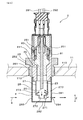
次に、粒子状物質検出センサ2の構造について、さらに詳細に説明する。図4に示すごとく、粒子状物質検出センサ2は、上記センサ本体部23と、保持部81と、ハウジング25と、固定部26とを備える。保持部81はセラミックス等の絶縁材料によって構成されている。この保持部81内に、センサ本体部23が保持されている。また、保持部81は、ハウジング25内に配されている。
Next, the structure of the particulate
ハウジング25は、固定部材26に挿入されている。この固定部材26の雄螺子部261を、排管11に形成した雌螺子部110に螺合してある。これにより、粒子状物質検出センサ2を排管11に固定している。
The
図4に示すごとく、ハウジング25には肩部251が形成されている。肩部251よりも先端側には、ばね部材83が配されている。肩部251を加締めることにより、ばね部材83の加圧力を利用して、保持部81の拡径部811をハウジング25の縮径部252に押し当てている。これにより、拡径部811と縮径部252との間から排ガスgが漏れないようにしている。
As shown in FIG. 4, the
また、粒子状物質検出センサ2は、電極用配線291とヒータ用配線292とを備える。これらの配線291,292は、それぞれ一対に設けられている。電極用配線291は、センサ本体部23内の上記電極21a,21bに電気接続している。また、ヒータ用配線292は、上記ヒータ22に電気接続している。
Further, the particulate
また、センサ本体部23の先端は、インナーカバー27とアウターカバー28との、2個のカバー27,28によって保護されている。アウターカバー28は、底部282と、側壁部281とを備える。側壁部281には、底部282に近い位置に、貫通孔283,284が形成されている。
The tip of the
また、インナーカバー27にも貫通孔(インナー側貫通孔273)が形成されている。インナーカバー27には、開口部272を形成してある。開口部272は、被堆積部20と上記底部282との間に形成されており、センサ本体部23の長手方向(Z方向)に開口している。また、インナーカバー27には、排ガスgを誘導する誘導板271が形成されている。
Further, through holes (inner side through holes 273) are also formed in the
排ガスgは、アウターカバー28の上流側貫通孔283を通り、側壁部281に当たって向きが変わった後、インナー側貫通孔273を通過する。この際、排ガスgは、誘導板271によって、被堆積部20に誘導される。これにより、より多くの排ガスgが被堆積部20に当たるようにしている。これによって、粒子状物質検出センサ2の応答性を高めている。
The exhaust gas g passes through the upstream through
排ガスgは、被堆積部20に当たった後、開口部272を通り、さらに下流側貫通孔284を通って、アウターカバー28の外側に排出される。
After the exhaust gas g hits the
次に、本形態における、制御部4のフローチャートについて説明する。図11に示すごとく、制御部4は、まず、粒子状物質検出センサ2の電極21a,21b間の電流を測定し、その測定値に基づいて、排ガスg中の粒子状物質3の量を算出する(ステップS1;測定モード)。
Next, the flowchart of the control unit 4 in the present embodiment will be described. As shown in FIG. 11, first, the control unit 4 measures the current between the
次いで、制御部4は、フィルタ6を再生する必要が有るか否かを判断する(ステップS2)。ここでYesと判断した場合は、ステップS3に移る。そして、フィルタ用ヒータを発熱させて、フィルタ6に捕集された粒子状物質3を燃焼させる。これにより、フィルタ6を再生する。
Next, the control unit 4 determines whether the filter 6 needs to be regenerated (step S2). If it is determined Yes here, the process proceeds to step S3. Then, the filter heater generates heat to burn the
その後、制御部4は、電極21a,21b間の電流値が所定の値を超えたか否か、すなわち電流が飽和したか否かを判断する。ここでYesと判断した場合は、ステップS5に移る。ここでは、ヒータ6を発熱させ、被堆積部20に堆積した粒子状物質3を燃焼し、除去する(発熱モード)。この際、制御部4は、ヒータ22の温度、すなわち被堆積部20の温度を600〜750℃にする。
Thereafter, the control unit 4 determines whether the current value between the
次に、発熱モードにおける被堆積部20の温度分布について説明する。図12に示すごとく、被堆積部20内の温度は均一ではなく、温度が高い箇所と、低い箇所とがある。本形態では、被堆積部20における最高温度Tmaxと、最低温度Tminとの差を100℃以内にしている。すなわち、平均温度Ttypと最高温度Tmaxとの差を50℃以内にすると共に、平均温度Ttypと最低温度Tminとの差を50℃以内にしている。
Next, the temperature distribution of the
次に、本形態の作用効果について説明する。本形態では、発熱モードにおいて、被堆積部20の温度を600〜750℃に制御している。
そのため、電極21の表面にアッシュ7が融着することを抑制できる。すなわち、上述したように、アッシュ7は、量子サイズ効果や共晶反応により、融点が900℃以下に低下することがあるが、750℃以下には殆どならない。そのため、被堆積部の温度の上限を750℃にすることにより、電極の表面にアッシュが融着することを抑制できる。
Next, the operation and effect of the present embodiment will be described. In the present embodiment, the temperature of the
Therefore, the fusion of the
また、本形態では、発熱モードにおける、被堆積部の温度の下限値を600℃にしている。そのため、発熱モードにおいて、粒子状物質が燃焼せず、電極21a,21b間に粒子状物質が残ってしまう不具合を抑制できる。
Further, in the present embodiment, the lower limit value of the temperature of the portion to be deposited in the heat generation mode is set to 600.degree. Therefore, in the heat generation mode, it is possible to suppress a problem that the particulate matter is not burned and the particulate matter remains between the
また、図12に示すごとく、本形態では、被堆積部20における、温度が最も高い部位と、温度が最も低い部位との温度差(Tmax−Tmin)を、100℃以下にしている。そのため、最高温度Tmaxと750℃との間、及び最低温度Tminと600℃との間に余裕ができ、被堆積部20のどの部位も、確実に、600〜750℃にすることが可能になる。被堆積部20の温度は、排ガスgの温度や流速によって変化しやすいが、Tmax−Tmin≦100(℃)にすれば、発熱モードにおいて排ガスgの温度や流速が急に変化しても、被堆積部20の全ての部位を600〜750℃にしやすくなる。
Further, as shown in FIG. 12, in the present embodiment, the temperature difference (T max −T min ) between the portion with the highest temperature and the portion with the lowest temperature in the
また、本形態では、図2に示すごとく、粒子状物質検出センサ2のセンサ本体部23を、四辺形板状に形成してある。このセンサ本体部23の端面200を、被堆積部20としている。そのため、被堆積部20の面積を小さくすることができ、被堆積部20内の温度ばらつきを小さくすることができる。したがって、発熱モードにおいて、被堆積部20の全ての部位を、600〜750℃にしやすい。
Further, in the present embodiment, as shown in FIG. 2, the sensor
また、図4に示すごとく、本形態では、粒子状物質検出センサ2のインナーカバー27に、排ガスgを被堆積部20に誘導する誘導板271を形成してある。そのため、被堆積部20に排ガスgが当たりやすくなり、粒子状物質検出センサ2の応答性を高めることができる。また、このようにすると、被堆積部20に粒子状物質3が堆積しやすくなり、アッシュ7も粒子状物質3と共に被堆積部20に堆積しやすくなる(図8参照)。しかし、本形態では、発熱モードにおける被堆積部20の温度の上限値を750℃にしているため、アッシュ7の堆積量が多くなっても、アッシュ7が融解して電極21に融着する不具合が生じにくい。
Further, as shown in FIG. 4, in the present embodiment, the
また、本形態では、図1に示すごとく、粒子状物質検出センサ2よりも排ガスgの上流側に、フィルタ6を設けてある。フィルタ6は、粒子状物質3の捕集効率が98%以下である。
そのため、排ガスgの圧損を低減することができる。すなわち、フィルタ6の捕集効率は、一般的には99.9%以上とされている。そのため、フィルタ6が故障しない限り、粒子状物質検出センサ2に到達する粒子状物質3、及びアッシュ7の量は微量である。しかし、このような捕集効率が高いフィルタ6は、排ガスgの圧損が高く、エンジン10の燃費が低下しやすい。そのため、フィルタ6の捕集効率を低下させ、排ガスgの圧損を低下させることが検討されている。本形態のように、フィルタ6の捕集効率を98%以下にすると、排ガスgの圧損を低下でき、燃費が低下することを抑制できる。
なお、フィルタ6の捕集効率を低下させると、粒子状物質検出センサ2に到達する粒子状物質3、及びアッシュ7の量が増加するが、本形態では、発熱モードにおける被堆積部20の温度の上限値を750℃にしているため、アッシュ7の量が増加しても、電極21に多くのアッシュ7が融着することを抑制できる。
Further, in the present embodiment, as shown in FIG. 1, the filter 6 is provided on the upstream side of the exhaust gas g than the particulate
Therefore, the pressure loss of the exhaust gas g can be reduced. That is, the collection efficiency of the filter 6 is generally 99.9% or more. Therefore, unless the filter 6 breaks down, the amounts of the
When the collection efficiency of the filter 6 is reduced, the amounts of the
また、フィルタ6の捕集効率は、80%以下とすることが好ましい。捕集効率を80%以下にすると、フィルタ6の圧損をより低減でき、燃費低下をより抑制できる。 Further, the collection efficiency of the filter 6 is preferably 80% or less. When the collection efficiency is 80% or less, the pressure loss of the filter 6 can be further reduced, and the decrease in fuel consumption can be further suppressed.
また、フィルタ6の捕集効率は、60%以下とすることがさらに好ましい。捕集効率を60%以下にすると、フィルタ6の圧損をさらに低減でき、燃費低下をさらに抑制できる。 Further, the collection efficiency of the filter 6 is more preferably 60% or less. When the collection efficiency is 60% or less, the pressure loss of the filter 6 can be further reduced, and the reduction in fuel consumption can be further suppressed.
以上のごとく、本形態によれば、粒子状物質検出センサの電極に排ガス中のアッシュが融着しにくい粒子状物質検出システムを提供することができる。 As described above, according to the present embodiment, it is possible to provide a particulate matter detection system in which the ash in the exhaust gas is not easily fused to the electrode of the particulate matter detection sensor.
なお、本形態では、制御部4と温度測定部5とを一体化している。すなわち、制御部4によってヒータ22の電気抵抗を測定し、その測定値を用いて、ヒータ22の温度、すなわち被堆積部20の温度を算出している。しかしながら、本発明はこれに限るものではなく、温度測定部5として、専用の温度センサを設けてもよい。
In the present embodiment, the control unit 4 and the temperature measurement unit 5 are integrated. That is, the control unit 4 measures the electrical resistance of the
1 粒子状物質検出システム
2 粒子状物質検出センサ
20 被堆積部
21 電極
22 ヒータ
3 粒子状物質
4 制御部
5 温度検出部
Reference Signs List 1 particulate
Claims (5)
該粒子状物質検出センサ(2)に接続した制御部(4)と、
上記被堆積部(20)の温度を測定する温度測定部(5)と、を備え、
上記センサ本体部(23)は長尺形状に形成され、該センサ本体部(23)の長手方向(Z)における先端側の端面(200)が上記被堆積部(20)となっており、該被堆積部(20)において上記第1電極(21a)と上記第2電極(21b)とが露出し、上記被堆積部(20)に露出した、上記第1電極(21a)及び上記第2電極(21b)の表面と、上記絶縁板(24)の表面とは面一になっており、
上記カバー(27,28)には、上記センサ本体部(23)のうち上記被堆積部(20)が形成された部位を取り囲むインナーカバー(27)と、該インナーカバー(27)の外側に配されたアウターカバー(28)とがあり、
上記インナーカバー(27)は、
上記インナーカバー(27)の側壁部における、上記被堆積部(20)よりも上記長手方向の先端側に形成されるとともに上記長手方向に対して交差する方向に複数並ぶ状態で形成された、上記排ガスが流れるインナー側貫通孔(273)と、上記インナーカバー(27)の底部に形成された、上記排ガスが流れる開口部(272)とを有し、
上記アウターカバー(28)は、上記アウターカバー(28)の側壁部における、上記長手方向に対して交差する方向に複数並ぶ状態で形成された、上記排ガスが流れるアウター側貫通孔(283,284)を有し、
上記インナー側貫通孔(273)の周縁部には、上記インナーカバー(27)の側壁部から上記長手方向の基端側に向けて傾斜して、上記インナー側貫通孔(273)を通過した上記排ガスを上記被堆積部(20)へ衝突させるためのガス誘導板(271)が形成され、
上記制御部(4)は、上記第1電極(21a)と上記第2電極(21b)との一対の電極(21)間を流れる電流を測定することにより、上記排ガスに含まれる上記粒子状物質(3)の量を測定する測定モードと、上記ヒータ(22)を発熱させ、上記被堆積部(20)に堆積した上記粒子状物質(3)を燃焼し除去する発熱モードとを行い、
上記制御部(4)は、上記発熱モードにおいて、上記温度測定部(5)によって測定される上記被堆積部(20)の温度が、600〜750℃となるように制御するよう構成されている、粒子状物質検出システム(1)。 A deposition site (20) on which particulate matter (3) in exhaust gas is deposited, a heater (22) for heating the deposition site (20), and a first electrode (21a) formed in a plate shape A sensor body (23) in which the second electrode (21b) and the second electrode (21b) are alternately stacked with the insulating plate (24) interposed therebetween, and a housing (25) for holding the sensor body (23) And a particulate matter detection sensor (2) having a cover (27, 28) attached to the housing (25) and protecting the sensor body (23) .
A control unit (4) connected to the particulate matter detection sensor (2);
Temperature measuring unit for measuring the temperature of the object to be deposited portion (20) and (5), provided with,
The sensor body (23) is formed in a long shape, and the end face (200) on the tip side in the longitudinal direction (Z) of the sensor body (23) is the deposition target (20). Said 1st electrode (21a) and said 2nd electrode which the said 1st electrode (21a) and said 2nd electrode (21b) exposed in the to-be-deposited part (20) and exposed to the said to-be-deposited part (20) The surface of (21b) and the surface of the insulating plate (24) are flush with each other,
The cover (27, 28) includes an inner cover (27) surrounding a portion of the sensor body (23) where the portion to be deposited (20) is formed, and the cover (27) is disposed outside the inner cover (27). There is an outer cover (28)
The inner cover (27) is
The side wall portion of the inner cover (27) is formed on the tip end side in the longitudinal direction with respect to the portion to be deposited (20) and is formed in a plurality in a row in the direction intersecting the longitudinal direction An inner through hole (273) through which exhaust gas flows, and an opening (272) through which the exhaust gas flows, which is formed at the bottom of the inner cover (27);
The outer cover (28) is formed in the side wall portion of the outer cover (28) in a plurality in the direction crossing the longitudinal direction, and the outer side through holes (283, 284) through which the exhaust gas flows Have
The peripheral portion of the inner through hole (273) is inclined from the side wall portion of the inner cover (27) toward the base end in the longitudinal direction and passes through the inner through hole (273) A gas induction plate (271) is formed to cause the exhaust gas to collide with the portion (20) to be deposited;
The control unit (4) measures the current flowing between the pair of electrodes (21) between the first electrode (21a) and the second electrode (21b) to thereby obtain the particulate matter contained in the exhaust gas. Performing a measurement mode for measuring the amount of (3), and a heat generation mode for burning and removing the particulate matter (3) deposited on the portion (20) by causing the heater (22) to generate heat;
The control unit (4) is configured to control the temperature of the portion to be deposited (20) measured by the temperature measurement unit (5) to be 600 to 750 ° C. in the heat generation mode. , Particulate matter detection system (1).
Priority Applications (2)
| Application Number | Priority Date | Filing Date | Title |
|---|---|---|---|
| JP2015162665A JP6501672B2 (en) | 2015-08-20 | 2015-08-20 | Particulate matter detection system |
| PCT/JP2016/071682 WO2017029948A1 (en) | 2015-08-20 | 2016-07-25 | Particulate matter detection system |
Applications Claiming Priority (1)
| Application Number | Priority Date | Filing Date | Title |
|---|---|---|---|
| JP2015162665A JP6501672B2 (en) | 2015-08-20 | 2015-08-20 | Particulate matter detection system |
Publications (3)
| Publication Number | Publication Date |
|---|---|
| JP2017040214A JP2017040214A (en) | 2017-02-23 |
| JP2017040214A5 JP2017040214A5 (en) | 2017-11-30 |
| JP6501672B2 true JP6501672B2 (en) | 2019-04-17 |
Family
ID=58052191
Family Applications (1)
| Application Number | Title | Priority Date | Filing Date |
|---|---|---|---|
| JP2015162665A Active JP6501672B2 (en) | 2015-08-20 | 2015-08-20 | Particulate matter detection system |
Country Status (2)
| Country | Link |
|---|---|
| JP (1) | JP6501672B2 (en) |
| WO (1) | WO2017029948A1 (en) |
Families Citing this family (1)
| Publication number | Priority date | Publication date | Assignee | Title |
|---|---|---|---|---|
| JP6358226B2 (en) | 2015-10-21 | 2018-07-18 | 株式会社デンソー | Particulate matter detector |
Family Cites Families (6)
| Publication number | Priority date | Publication date | Assignee | Title |
|---|---|---|---|---|
| JP5094702B2 (en) * | 2008-12-24 | 2012-12-12 | 本田技研工業株式会社 | Particulate matter detector |
| JP2011224538A (en) * | 2009-12-01 | 2011-11-10 | Ibiden Co Ltd | Honeycomb filter and apparatus for cleaning exhaust gas |
| JP5500028B2 (en) * | 2010-09-30 | 2014-05-21 | 株式会社デンソー | Method for manufacturing particulate matter detection sensor |
| JP5606356B2 (en) * | 2011-02-17 | 2014-10-15 | 株式会社日本自動車部品総合研究所 | Particulate matter detector |
| WO2012124054A1 (en) * | 2011-03-15 | 2012-09-20 | トヨタ自動車株式会社 | Control device of internal combustion engine |
| EP2784277B1 (en) * | 2011-11-25 | 2018-12-26 | Toyota Jidosha Kabushiki Kaisha | Control device for internal combustion engine |
-
2015
- 2015-08-20 JP JP2015162665A patent/JP6501672B2/en active Active
-
2016
- 2016-07-25 WO PCT/JP2016/071682 patent/WO2017029948A1/en active Application Filing
Also Published As
| Publication number | Publication date |
|---|---|
| JP2017040214A (en) | 2017-02-23 |
| WO2017029948A1 (en) | 2017-02-23 |
Similar Documents
| Publication | Publication Date | Title |
|---|---|---|
| JP6207158B2 (en) | Soot particle sensor system | |
| JP6426072B2 (en) | Filter failure detection device, particulate matter detection device | |
| JP5751330B2 (en) | Control device for internal combustion engine | |
| JP5327379B2 (en) | Control device for internal combustion engine | |
| JP2008032686A (en) | Soot sensor | |
| JP2014529356A (en) | Method and apparatus for measuring the concentration of soot particles in exhaust gases, in particular exhaust gases from internal combustion engines | |
| US10208643B2 (en) | Particulate matter detection apparatus | |
| JP2011080942A (en) | Particulate detection sensor | |
| JP6358226B2 (en) | Particulate matter detector | |
| JPS59196453A (en) | Particulate detecting element | |
| JP6501672B2 (en) | Particulate matter detection system | |
| US10274400B2 (en) | Method and system for exhaust particulate matter sensing | |
| JP5790777B2 (en) | Control device and control method for internal combustion engine | |
| WO2016147711A1 (en) | Particulate matter detection system | |
| JP2009042021A (en) | Particulate discharge amount detector | |
| CN107525750B (en) | Method and system for exhaust particulate matter sensing | |
| US20170030753A1 (en) | Sensor element, sensor module, measuring assembly and exhaust-gas re-circulation system comprising a sensor element of this type, and production method | |
| WO2016052734A1 (en) | Filter failure detection device, and particulate matter detection device | |
| JP6552444B2 (en) | Particulate matter detection device and exhaust gas purification device for internal combustion engine | |
| JP6421736B2 (en) | Particulate matter detector | |
| JP2009041416A (en) | Failure diagnosis device for particulate charger | |
| JP6098528B2 (en) | Filter abnormality judgment system | |
| JP6358851B2 (en) | Particulate matter detection device and particulate matter detection method | |
| JP6805531B2 (en) | Sensor | |
| US10914668B2 (en) | Sensor for detecting particles |
Legal Events
| Date | Code | Title | Description |
|---|---|---|---|
| A521 | Request for written amendment filed |
Free format text: JAPANESE INTERMEDIATE CODE: A523 Effective date: 20171020 |
|
| A621 | Written request for application examination |
Free format text: JAPANESE INTERMEDIATE CODE: A621 Effective date: 20171020 |
|
| A131 | Notification of reasons for refusal |
Free format text: JAPANESE INTERMEDIATE CODE: A131 Effective date: 20180626 |
|
| A521 | Request for written amendment filed |
Free format text: JAPANESE INTERMEDIATE CODE: A523 Effective date: 20180809 |
|
| A131 | Notification of reasons for refusal |
Free format text: JAPANESE INTERMEDIATE CODE: A131 Effective date: 20181016 |
|
| A521 | Request for written amendment filed |
Free format text: JAPANESE INTERMEDIATE CODE: A523 Effective date: 20181211 |
|
| TRDD | Decision of grant or rejection written | ||
| A01 | Written decision to grant a patent or to grant a registration (utility model) |
Free format text: JAPANESE INTERMEDIATE CODE: A01 Effective date: 20190219 |
|
| A61 | First payment of annual fees (during grant procedure) |
Free format text: JAPANESE INTERMEDIATE CODE: A61 Effective date: 20190319 |
|
| R150 | Certificate of patent or registration of utility model |
Ref document number: 6501672 Country of ref document: JP Free format text: JAPANESE INTERMEDIATE CODE: R150 |
|
| R250 | Receipt of annual fees |
Free format text: JAPANESE INTERMEDIATE CODE: R250 |
|
| R250 | Receipt of annual fees |
Free format text: JAPANESE INTERMEDIATE CODE: R250 |
|
| R250 | Receipt of annual fees |
Free format text: JAPANESE INTERMEDIATE CODE: R250 |