JP6500599B2 - Condenser - Google Patents
Condenser Download PDFInfo
- Publication number
- JP6500599B2 JP6500599B2 JP2015106669A JP2015106669A JP6500599B2 JP 6500599 B2 JP6500599 B2 JP 6500599B2 JP 2015106669 A JP2015106669 A JP 2015106669A JP 2015106669 A JP2015106669 A JP 2015106669A JP 6500599 B2 JP6500599 B2 JP 6500599B2
- Authority
- JP
- Japan
- Prior art keywords
- header tank
- refrigerant
- internal space
- condenser
- storage container
- Prior art date
- Legal status (The legal status is an assumption and is not a legal conclusion. Google has not performed a legal analysis and makes no representation as to the accuracy of the status listed.)
- Expired - Fee Related
Links
Images


Landscapes
- Details Of Heat-Exchange And Heat-Transfer (AREA)
- Heat-Exchange Devices With Radiators And Conduit Assemblies (AREA)
Description
本発明は、受液器を備える凝縮器に関する。 The present invention relates to a condenser comprising a receiver.
近年、市場では、従来の凝縮器の放熱性能を維持しつつ、搭載性のよい薄幅な凝縮器が求められている。なお、薄幅な凝縮器は、空気流れ方向の幅寸法が小さい凝縮器である。 In recent years, in the market, there is a demand for thin-walled condensers that can be easily mounted while maintaining the heat radiation performance of conventional condensers. The thin condenser is a condenser having a small width in the air flow direction.
特に、受液器は、気相冷媒と液相冷媒とを分離すると共に、冷凍サイクル内の余剰冷媒を貯留する機器であり、比較的大きな容積が必要となる。このため、薄幅な凝縮器を実現するためには、受液器の幅方向寸法(空気流れ方向の寸法)の小型化を図ることが重要となる。 In particular, the receiver is a device that separates the gas phase refrigerant and the liquid phase refrigerant, and stores excess refrigerant in the refrigeration cycle, and requires a relatively large volume. For this reason, in order to realize a thin condenser, it is important to reduce the size in the width direction (the size in the air flow direction) of the liquid receiver.
これに対して、凝縮器のコア部(熱交換部)の側方部に配置された縦置きの受液器に加えて、コア部の上方側に沿って横に寝かせた姿勢で配置された横置きの受液器を備える構成が種々提案されている(例えば、特許文献1参照)。 On the other hand, in addition to the vertically disposed receiver disposed on the side of the core portion (heat exchange portion) of the condenser, it is disposed in a posture lying horizontally along the upper side of the core portion. Various configurations provided with a horizontally disposed receiver have been proposed (see, for example, Patent Document 1).
特許文献1に開示された凝縮器は、縦置きの受液部と横置きの受液器とが内部で連通するように、連結配管を介して各受液器同士を接続する構成となっている。なお、横置きの受液器は、サイドプレート上に配置されている。
The condenser disclosed in
しかしながら、特許文献1に記載の凝縮器では、冷媒に含まれる水分を吸着する吸着剤を、液相冷媒を貯留する受液器の内部に収容する構成としている。このような構成では、受液器の内部において、液相冷媒を貯留する空間に加えて、受液器の内部に吸着剤を収容する収容空間を確保する必要がある。このことは、受液器における幅方向寸法(空気流れ方向の寸法)の小型化を難しくさせる一因となることから、好ましくない。
However, in the condenser described in
本発明は上記点に鑑みて、受液器における幅方向寸法を抑えることが可能な凝縮器を提供することを目的とする。 An object of this invention is to provide the condenser which can suppress the width direction dimension in a receiver in view of the said point.
請求項1に記載の発明は、
冷媒が流通する複数のチューブ(2a)を上下に積層して構成され、チューブの外側を流れる外部流体との熱交換により冷媒を放熱させるコア部(2)と、
チューブの積層方向に沿って延びると共にコア部におけるチューブの長手方向の一端側に接続される第1ヘッダタンク(5)と、
チューブの積層方向に沿って延びると共にコア部におけるチューブの長手方向の他端側に接続される第2ヘッダタンク(6)と、
チューブの積層方向に沿って延びると共に第1ヘッダタンクに隣接して配置され、第1ヘッダタンクの内部に連通する受液器(10)と、
を備える凝縮器を対象としている。
The invention according to
A core portion (2) configured by vertically laminating a plurality of tubes (2a) through which the refrigerant flows, and emitting heat from the refrigerant by heat exchange with an external fluid flowing outside the tubes;
A first header tank (5) extending along the stacking direction of the tubes and connected to one longitudinal end of the tubes in the core portion;
A second header tank (6) extending along the stacking direction of the tubes and connected to the other end of the tube in the longitudinal direction in the core portion;
A receiver (10) extending along the stacking direction of the tubes and disposed adjacent to the first header tank and in communication with the interior of the first header tank;
Intended for condensers equipped with
上記目的を達成するため、請求項1に記載の発明は、
水分を吸着する乾燥剤(36)と、
少なくとも乾燥剤を収容する収容容器(30)と、を備え、
収容容器は、第2ヘッダタンクに隣接して配置され、第2ヘッダタンクの内部に存する冷媒が流入するように、第2ヘッダタンクの内部に連通しており、
第2ヘッダタンクには、
コア部を構成する一部のチューブを通過した冷媒を集合させる中間集合空間(61b)と、
中間集合空間に集合した冷媒を残部のチューブの少なくとも一部へ分配する中間分配空間(61d)と、が形成されており、
中間集合空間および中間分配空間は、収容容器の内部空間を介して連通していることを特徴としている。
In order to achieve the above object, the invention according to
A desiccant (36) that absorbs moisture,
And (d) a container (30) for containing at least the desiccant.
The storage container is disposed adjacent to the second header tank, and is in communication with the inside of the second header tank so that the refrigerant existing inside the second header tank flows in,
The second header tank
An intermediate collecting space (61b) for collecting the refrigerant that has passed through a part of the tubes constituting the core portion;
An intermediate distribution space (61d) for distributing the refrigerant collected in the intermediate collection space to at least a part of the remaining tube;
The intermediate collection space and the intermediate distribution space are characterized in that they communicate with each other via the internal space of the storage container.
このように、受液器とは別に構成される収容容器に乾燥剤を収容する構成とすれば、受液器に乾燥剤を収容する収容空間を設ける必要がないので、受液器の内部に乾燥剤を収容する構成に比べて、受液器における幅寸法を小型化することが可能となる。 As described above, when the desiccant is stored in the storage container configured separately from the liquid receiver, there is no need to provide a storage space for containing the desiccant in the liquid receiver, and therefore, the receiver can be provided inside the liquid receiver. As compared with the configuration in which the desiccant is contained, the width dimension of the receiver can be reduced.
さらに、受液器に連通する第1ヘッダタンクではなく、第2ヘッダタンクに対して収容容器を連通させる構成としている。これによれば、収容容器と受液器とが互いに干渉しない配置構成となることから、収容容器との干渉を考慮せずに、受液器における幅寸法を小型化することが可能となる。 Further, the container is communicated with the second header tank, not the first header tank communicating with the liquid receiver. According to this configuration, since the storage container and the receiver do not interfere with each other, the width dimension of the receiver can be reduced without considering the interference with the storage container.
従って、請求項1に記載の発明によれば、受液器における幅方向寸法を抑えて、薄幅な凝縮器を実現することが可能となる。
Therefore, according to the first aspect of the present invention, it is possible to realize a thin condenser by suppressing the widthwise dimension of the liquid receiver.
なお、この欄および特許請求の範囲で記載した各手段の括弧内の符号は、後述する実施形態に記載の具体的手段との対応関係の一例を示すものである。 In addition, the code | symbol in the parenthesis of each means described by this column and the claim shows an example of the correspondence with the specific means as described in embodiment mentioned later.
以下、本発明の実施形態について図面を参照して説明する。なお、以下の各実施形態において、先行する実施形態で説明した事項と同一もしくは均等である部分には、同一の参照符号を付し、その説明を省略する場合がある。また、各実施形態において、構成要素の一部だけを説明している場合、構成要素の他の部分に関しては、先行する実施形態において説明した構成要素を適用することができる。以下の実施形態は、特に組み合わせに支障が生じない範囲であれば、特に明示していない場合であっても、各実施形態同士を部分的に組み合わせることができる。 Hereinafter, embodiments of the present invention will be described with reference to the drawings. In the following embodiments, parts that are the same as or equivalent to the items described in the preceding embodiments may be denoted by the same reference numerals, and the description thereof may be omitted. In addition, in each embodiment, when only a part of the components is described, the components described in the preceding embodiments can be applied to other parts of the components. The following embodiments can be partially combined with each other even if they are not particularly specified as long as there is no problem in particular in the combination.
(第1実施形態)
本実施形態に係る凝縮器1は、車両用の空調装置に適用される蒸気圧縮式の冷凍サイクルを構成する熱交換器である。冷凍サイクルは、圧縮機、凝縮器1、減圧機構、蒸発器等を順次配管接続した閉回路として構成される。本実施形態の冷凍サイクルは、圧縮機として、エンジンからの動力により駆動するエンジン駆動式の圧縮機を採用している。なお、圧縮機は、電動モータからの動力により駆動する電動圧縮機を採用してもよい。
First Embodiment
The
凝縮器1は、図示しない圧縮機から吐出された高温高圧の気相冷媒を外部流体である車室外空気と熱交換させて凝縮させる。凝縮器1は、内部で凝縮した冷媒を図示しない減圧機構を介して冷媒を蒸発させる図示しない蒸発器側へ導出する。
The
凝縮器1は、車両を駆動する内燃機関(エンジン)が設置されたエンジンルーム内に配置されている。凝縮器1は、例えば、エンジンルーム内の最前部に形成された走行風の導入路に配置されている。
The
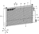
まず、本実施形態の凝縮器1の全体構成について、図1を参照して説明する。ここで、図1の上下、左右、前後を示す各矢印は車両搭載状態における上下方向、左右方向、前後方向を示している。このことは、図1以外の図面においても同様である。
First, the entire configuration of the
本実施形態の凝縮器1は、主たる構成要素として、コア部2、一対のサイドプレート3、4、一対のヘッダタンク5、6、一対のコネクタ7、8、受液器(モジュレータ)10、および収容容器30を備える。
The
凝縮器1を構成する主な部材は、アルミニウムやアルミニウム合金等のアルミニウム製の金属材料で構成されている。凝縮器1は、金属材料で構成される各部材が組み付けられた状態で、各部材の必要な部位に予め設けられたろう材によりろう付け接合されている。
The main members constituting the
コア部2は、内部を冷媒が流通する複数のチューブ2aを上下に積層した積層体である。コア部2は、チューブ2aを流れる冷媒をチューブ2aの外側を流れる外部流体である空気と熱交換させて放熱させる熱交換部を構成する。
The
コア部2は、隣接するチューブ2a間に、冷媒と空気との熱交換を促進するフィン2bが設けられている。本実施形態のフィン2bは、波状に曲折されたコルゲートフィンで構成されている。なお、フィン2bは、コルゲートフィンに限らず、プレートフィン等で構成されていてもよい。
The
本実施形態の各チューブ2aは、扁平な断面を有する単穴あるいは多穴の管で構成されている。各チューブ2aは、隣り合うチューブ2aの間を空気が流通するように、互いに所定間隔を設けて積層されている。
Each
本実施形態のコア部2は、冷媒を凝縮させる凝縮部21、および受液器10から流出した液相冷媒を冷却する過冷却部(サブクーラ)22を有する。本実施形態のコア部2は、過冷却部22が凝縮部21の下方側に位置する構成となっている。なお、本実施形態では、コア部2における図1の太い二点鎖線DLよりも上方側に位置する部位が凝縮部21を構成し、図1の太い二点鎖線よりも下方側に位置する部位が過冷却部22を構成している。
The
一対のサイドプレート3、4は、コア部2を補強する補強部材である。本実施形態のサイドプレート3、4は、コア部2におけるチューブ2aの積層方向(図1の上下方向)の両端部に配置されている。
The pair of
一対のサイドプレート3、4のうち、上端側プレート3は、コア部2における上端に位置するフィン2bに対して接合されている。また、一対のサイドプレート3、4のうち、下端側プレート4は、コア部2における下端に位置するフィン2bに対して接合されている。
Of the pair of
一対のヘッダタンク5、6は、各チューブ2aを流れる冷媒の集合・分配を行うタンクとして機能する。一対のヘッダタンク5、6は、チューブ2aの長手方向両端部に接続されている。
The pair of
具体的には、図1の左側に示す第1ヘッダタンク5は、チューブ2aの積層方向に沿って延びると共に、コア部2におけるチューブ2aの長手方向の一端側に接続されている。また、図1の右側に示す第2ヘッダタンク6は、チューブ2aの積層方向に沿って延びると共に、コア部2におけるチューブ2aの長手方向の他端側に接続されている。
Specifically, the
各ヘッダタンク5、6は、チューブ2aの積層方向に沿って延びる筒状の中空部材で構成されている。各ヘッダタンク5、6は、その内部に各チューブ2aの内部と連通する内部空間が形成されている。
Each
一対のコネクタ7、8は、凝縮器1における冷媒の出入口として機能する。一対のコネクタ7、8のうち、冷媒の入口部を構成する入口側コネクタ7は、第2ヘッダタンク6における上端側に近接する位置に接合されている。入口側コネクタ7には、圧縮機から吐出された冷媒が流通する外部配管が接続される。
The pair of
また、一対のコネクタ7、8のうち、冷媒の出口部を構成する出口側コネクタ8は、収容容器30における下端側に近接する位置に接合されている。出口側コネクタ8は、凝縮器1を通過した冷媒を減圧機構側へ導出する外部配管が接続される。
Further, of the pair of
受液器10は、コア部2の凝縮部21から流出した冷媒を液相冷媒と気相冷媒に分離して、液相冷媒を一時的に貯留するタンクである。受液器10の内部には、液相冷媒を貯留する冷媒貯留空間が形成されている。受液器10は、冷凍サイクルの負荷変動に合わせて、サイクル内を循環する冷媒の循環量を調整する役割を果たしている。
The
受液器10は、チューブ2aの積層方向に沿って延びると共に、第1ヘッダタンク5に隣接して配置されている。受液器10は、第1ヘッダタンク5の内部に連通するように、第1ヘッダタンク5に対して接合されている。受液器10の内部には、円柱状の空間が形成されている。受液器10は、耐圧性を考慮して内壁の断面形状を円形状とすることが望ましい。
The
収容容器30は、乾燥剤36を収容する容器である。収容容器30の内部には、乾燥剤36を収容する収容空間が形成されている。収容容器30は、第2ヘッダタンク6に隣接して配置されている。収容容器30は、第2ヘッダタンク5の内部に存する冷媒が流入するように、第2ヘッダタンク6の内部に連通している。
The
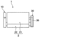
次に、本実施形態の凝縮器1の詳細について、図2を参照して説明する。図2は凝縮器1の模式的な断面図である。なお、説明の便宜のため、図2では、コア部2を構成するチューブ2aおよびフィン2bの図示を省略している。このことは、以降の図面においても同様である。
Next, details of the
図2に示すように、本実施形態の第1ヘッダタンク5には、内部空間を上下に仕切る仕切部材として、2つのセパレータ5a、5bが設けられている。第1ヘッダタンク5の内部は、2つのセパレータ5a、5bにより、3つの内部空間51a〜51cに区分されている。
As shown in FIG. 2, in the
第1ヘッダタンク5の3つの内部空間51a〜51cは、上方の内部空間51a、および中央の内部空間51bがコア部2の凝縮部21に連通し、下方の内部空間51cがコア部2の過冷却部22に連通している。
In the three
第1ヘッダタンク5における上方の内部空間51aは、凝縮部21における冷媒の流れ方向を転向させる空間である。
The upper
第1ヘッダタンク5における中央の内部空間51bは、凝縮部21を通過した冷媒を集合させる空間である。本実施形態の中央の内部空間51bは、後述する受液器10における冷媒導入部101aを介して受液器10の冷媒貯留空間に連通している。このため、凝縮部21を通過した冷媒は、第1ヘッダタンク5の中央の内部空間51b、および冷媒導入部101aを介して、受液器10の内部に導入される。
The central
第1ヘッダタンク5における下方の内部空間51cは、過冷却部22へ冷媒を分配する空間である。本実施形態の下方の内部空間51cは、後述する受液器10の冷媒導出部101bを介して受液器10の冷媒貯留空間に連通している。このため、受液器10の内部の液相冷媒は、後述する冷媒導出部101b、および第1ヘッダタンク5の下方の内部空間51cを介して過冷却部22へ導出される。
The lower
ここで、第1ヘッダタンク5には、中央の内部空間51bを形成する部位に、後述する冷媒導入部101aを介して、受液器10の内部と中央の内部空間51bとを連通させる貫通穴52aが形成されている。
Here, in the
また、第1ヘッダタンク5には、下方の内部空間51cを形成する部位に、後述する冷媒導出部101bを介して、受液器10の内部と下方の内部空間51cとを連通させる貫通穴52bが形成されている。
Further, in the
続いて、本実施形態の第2ヘッダタンク6には、内部空間を上下に仕切る仕切部材として2つのセパレータ6a、6bが設けられている。各セパレータ6a、6bは、コア部2の凝縮部21における冷媒の流れがS字を描く流れとなるように設定されている。
Subsequently, in the
具体的には、第2ヘッダタンク6のセパレータ6aは、上下方向において、第1ヘッダタンク5のセパレータ5aよりも上方となる位置に配置されている。第2ヘッダタンク6のセパレータ6bは、上下方向において第1ヘッダタンク5のセパレータ5bに対応する位置に配置されている。
Specifically, the
第2ヘッダタンク6の内部には、2つのセパレータ6a、6bにより、3つの内部空間61a〜61cに区分されている。各内部空間61a〜61cは、上方の内部空間61aおよび中央の内部空間61bがコア部2の凝縮部21に連通し、下方の内部空間61cがコア部2の過冷却部22に連通している。
The
第2ヘッダタンク6における上方の内部空間61aは、凝縮部21へ冷媒を分配する空間である。第2ヘッダタンク6の上方の内部空間61aは、凝縮部21を構成するチューブ2aを介して、第1ヘッダタンク5の上方の内部空間51aに連通している。
The upper
第2ヘッダタンク6における中央の内部空間61bは、凝縮部21における冷媒の流れ方向を転向させる空間である。第2ヘッダタンク6の中央の内部空間61bは、凝縮部21を構成するチューブ2aを介して、第1ヘッダタンク5の上方の内部空間51a、および中央の内部空間51bに連通している。本実施形態では、第2ヘッダタンク6の中央の内部空間61bが、コア部2を構成する一部のチューブ2aを通過した冷媒を集合させる中間集合空間を構成している。
The central
第2ヘッダタンク6における下方の内部空間61cは、過冷却部22を通過した冷媒を集合させる空間である。第2ヘッダタンク6の下方の内部空間61cは、過冷却部22を構成するチューブ2aを介して、第1ヘッダタンク5の下方の内部空間51cに連通している。本実施形態では、第2ヘッダタンク6の下方の内部空間61cが、過冷却部22を通過した冷媒を集合させる冷媒集合空間を構成している。
The lower
ここで、第2ヘッダタンク6には、上方の内部空間61aに圧縮機から吐出された高温高圧の冷媒が導入されるように、上方の内部空間61aを形成する部位に入口側コネクタ7が接続されている。
Here, the inlet-
また、第2ヘッダタンク6には、下方の内部空間61cを形成する部位に、後述する収容側連通部321を介して、収容容器30の内部と下方の内部空間61cとを連通させる貫通穴62aが形成されている。
Further, in the
続いて、本実施形態の受液器10について説明する。受液器10は、チューブ2aの積層方向に沿って延びる円筒状の筒状部101、筒状部101の上端部および下端部を閉塞する一対の蓋部102、103を有する。説明の便宜のため、以下、受液器10における筒状部101を受液側筒状部101と呼ぶことがある。
Subsequently, the
受液側筒状部101は、外径が第1ヘッダタンク5の前後方向の寸法と同程度の大きさとなっている。受液側筒状部101は、左右方向において、第1ヘッダタンク5における凝縮部21および過冷却部22に接続される部位に対して対向配置されている。
The liquid receiving side
受液側筒状部101には、第1ヘッダタンク5の貫通穴52aに対応する部位に、内部空間51bから受液器10の冷媒貯留空間へ冷媒を導入する冷媒導入部101aが設けられている。冷媒導入部101aは、第1ヘッダタンク5の中央の内部空間61bを形成する部位に接合されている。
The liquid receiving side
また、受液側筒状部101には、第1ヘッダタンク5の貫通穴52bに対応する部位に、受液器10の冷媒貯留空間から内部空間51cへ液相冷媒を導出する冷媒導出部101bが設けられている。冷媒導出部101bは、第1ヘッダタンク5の下方の内部空間51cを形成する部位に接合されている。
In the liquid receiving side
次に、収容容器30について説明する。収容容器30は、第2ヘッダタンク6よりもチューブ2aの積層方向の長さが小さくなっている。本実施形態の収容容器30は、その上端部が第2ヘッダタンク6の上端部よりも下方側に位置している。
Next, the
より具体的には、本実施形態の収容容器30は、入口側コネクタ7と干渉しないように、その上端部が入口側コネクタ7よりも下方側に位置している。換言すれば、入口側コネクタ7は、第2ヘッダタンク6における収容容器30の上端部よりも上方側の部位に接続されている。
More specifically, the upper end portion of the
収容容器30は、チューブ2aの積層方向に沿って延びる円筒状の筒状部31、筒状部31の端部を補強する筒状のサポート部32、サポート部32の端部を閉塞するネジ式のタンクキャップ34、筒状部31の上端側を閉塞する蓋部33を有する。説明の便宜のため、以下、収容容器30における筒状部31を収容側筒状部31と呼ぶことがある。
The
収容側筒状部31は、左右方向において、第2ヘッダタンク6における凝縮部21に接続される部位に対して対向配置されている。収容側筒状部31は、外径が第2ヘッダタンク6の前後方向の寸法と同程度の大きさとなっている。
The housing-
収容側筒状部31は、第2ヘッダタンク6の中央の内部空間61bを形成する部位に連結された中間連結部311を有する。収容側筒状部31は、第2ヘッダタンク6に対して、中間連結部311を介して接続されている。
The housing-side
本実施形態の中間連結部311は、第2ヘッダタンク6と収容側筒状部31とを連結する部位であり、中間連結部311を介して、第2ヘッダタンク6と収容容器30とは連通していない。また、中間連結部311は、収容側筒状部31と一体に成形されている。なお、中間連結部311は、収容側筒状部31と別部材で構成されていてもよい。
The
サポート部32は、左右方向において、第2ヘッダタンク6における過冷却部22に接続される部位に対して対向配置されている。サポート部32には、第2ヘッダタンク6の貫通穴62aに対応する部位に、第2ヘッダタンク6の下方の内部空間61cから冷媒を導入する収容側連通部321が設けられている。収容側連通部321は、第2ヘッダタンク6の下方の内部空間61cを形成する部位に接合されている。
The
また、サポート部32には、収容側連通部321を介して収容容器30の内部に流入した液相冷媒を外部へ導出するために、出口側コネクタ8が接続されている。出口側コネクタ8には、液相冷媒を外部へ導出する導出流路8aが形成されている。従って、本実施形態の収容容器10は、過冷却部22を通過した液相冷媒を出口側コネクタ8へ導く冷媒通路を構成する。
Further, the
ここで、本実施形態の収容容器30の内部には、フィルタ35、および乾燥剤36が配置されている。フィルタ35は、冷凍サイクル内の異物を捕捉する部材である。本実施形態のフィルタ35は、液相冷媒が流通するタンクキャップ34の上部に配置されている。フィルタ35は、例えば、円筒状の網状体で構成される。
Here, the
乾燥剤36は、冷凍サイクルに混入した水を吸着する部材である。本実施形態の乾燥剤36は、収容容器30の内部において、少なくとも一部が冷媒の液面よりも下方となるように配置されている。
The
乾燥剤36は、冷媒が通過可能な袋状部材の内部に粒状の乾燥剤を収容して構成される。粒状の乾燥剤としては、例えば、冷媒中の水分濃度が低い状況でも吸着性能に優れるシリカゲルやゼオライトを採用することができる。
The
タンクキャップ34は、サポート部32に対して着脱可能に構成されている。タンクキャップ34は、フィルタ35を保持する保持部材を構成している。収容容器30は、サポート部32からタンクキャップ34を着脱することで、収容容器30内部に収容されたフィルタ35や乾燥剤36を交換することが可能となっている。
The
次に、上述のように構成された凝縮器1における冷媒の流れ方について説明する。エンジンの作動時に、空調の作動スイッチがオンされて、空調装置の運転が開始されると、エンジンからの動力により圧縮機が駆動して、圧縮機が冷媒を圧縮して吐出する。これにより、圧縮機から吐出された高温高圧の気相冷媒が、入口側コネクタ7を介して第2ヘッダタンク6の上方の内部空間61aに流入する。
Next, the flow of the refrigerant in the
内部空間61aに流入した冷媒は、図2の矢印に示すように、凝縮部21における上方側のチューブ2aに分配されて、当該チューブ2aを通過する際に空気と熱交換して冷却された後、第1ヘッダタンク5の上方の内部空間51aに流入する。
The refrigerant having flowed into the
内部空間51aに流入した冷媒は、凝縮部21における中段付近のチューブ2aに分配されて、当該チューブ2aを通過する際に空気と熱交換して冷却された後、第2ヘッダタンク6の中央の内部空間61bに流入する。
The refrigerant that has flowed into the
内部空間61bに流入した冷媒は、凝縮器1における下方側のチューブ2aに分配されて、当該チューブ2aを通過する際に空気と熱交換して冷却された後、第1ヘッダタンク5の中央の内部空間51bに流入する。内部空間51bには、気相冷媒を一部に含む飽和液冷媒またはある程度の過冷却度を有する過冷却液冷媒が流入する。
The refrigerant having flowed into the
内部空間51bに流入した冷媒は、冷媒導入部101aを介して受液器10に流入して、受液器10の内部で冷媒の比重差により気相冷媒と液相冷媒とに分離される。受液器10の内部には、比重の軽い気相冷媒が上方側に集まり、気相冷媒よりも比重の重い液相冷媒が下方側に集まって貯留される。受液器10の内部に貯留された液相冷媒は、その一部が冷媒導出部101bを介して第1ヘッダタンク5の下方の内部空間51cに流入する。
The refrigerant that has flowed into the
内部空間51cに流入した液相冷媒は、過冷却部22を構成するチューブ2aに分配されて、当該チューブ2aを通過する際に空気と熱交換して過冷却された後、第2ヘッダタンク6の内部空間61cに流入する。
The liquid-phase refrigerant that has flowed into the
内部空間61cに流入した過冷却度を有する液相冷媒は、収容側連通部321を介して収容容器30の内部に流入する。収容容器30の内部に流入した液相冷媒は、フィルタ35で異物が捕捉されると共に、乾燥剤36により水分が吸着された後、出口側コネクタ8を介して減圧機構側へ流出する。
The liquid-phase refrigerant having the degree of supercooling that has flowed into the
ここで、図3は、コア部MCの左右方向の一方に受液器MTを設け、当該受液器MTの内部に乾燥剤DAを収容した凝縮器(比較例)CPの模式図である。図4は、本実施形態に係る凝縮器1の模式図である。そして、図5は、図3に示す凝縮器CPの受液器MTと本実施形態に係る凝縮器1の受液器10との大きさの違いを説明するための要部断面図である。図5は、凝縮器1における受液器10を含む要部を左右方向に切断した切断面を示している。
Here, FIG. 3 is a schematic view of a condenser (comparative example) CP in which the liquid receiver MT is provided on one side in the left-right direction of the core portion MC and the desiccant DA is accommodated inside the liquid receiver MT. FIG. 4 is a schematic view of the
図5に示すように、比較例の凝縮器CPの場合、受液器MTは、冷凍サイクルに負荷変動の調整に必要な冷媒量を貯留すると共に、乾燥剤DAを収容する空間を確保するために、受液器MTの直径を第1ヘッダタンク5に対して大きくする必要がある。
As shown in FIG. 5, in the case of the condenser CP of the comparative example, the liquid receiver MT stores the amount of refrigerant necessary for adjustment of load fluctuation in the refrigeration cycle and secures a space for containing the desiccant DA. In addition, it is necessary to make the diameter of the receiver MT larger than that of the
このため、比較例の凝縮器CPでは、第1ヘッダタンク5に対して寸法A、Bの分だけ受液器MTが前方および右方に突き出てしまう。このことは、凝縮器CPの周囲に無駄なスペースが生ずる要因となることから、好ましくない。
For this reason, in the condenser CP of the comparative example, the receiver MT protrudes forward and right with respect to the
これに対して、本実施形態の凝縮器1の場合、乾燥剤36を受液器10ではなく、収容容器30に収容する構成としている。このため、受液器10の直径を受液器MTの直径よりも小さくすることが可能となる。すなわち、本実施形態の凝縮器1では、受液器10の直径をコア部2の前後寸法や第1ヘッダタンク5の前後寸法に近づけることが可能となる。
On the other hand, in the case of the
以上説明した本実施形態の凝縮器1は、受液器10とは別に構成される収容容器30に対して乾燥剤36を収容する構成としている。これによれば、受液器10の内部に乾燥剤36を収容するためのスペースを確保する必要がない。このため、本実施形態の凝縮器1は、受液器10の内部に乾燥剤36を収容する構成に比べて、受液器10における幅方向の寸法(前後方向の寸法)を小型化することが可能となる。
The
さらに、本実施形態では、受液器10に連通する第1ヘッダタンク5ではなく、第2ヘッダタンク6に対して収容容器30を隣接配置する構成としている。これによれば、収容容器30と受液器10とが互いに干渉しない配置構成となることから、収容容器30との干渉を考慮せずに、受液器10における幅方向の寸法の小型化を図ることができる。
Furthermore, in the present embodiment, the
従って、本実施形態の凝縮器1によれば、受液器10における幅方向の寸法を抑えて、薄幅な凝縮器1を実現することが可能となる。
Therefore, according to the
また、本実施形態では、収容容器30を第2ヘッダタンク6における冷媒集合空間を構成する下方の内部空間61cに連通させる構成としている。これによれば、過冷却部22を通過した液相冷媒が収容容器30に流入するので、過冷却部22を通過した液相冷媒に含まれる水分を乾燥剤36で効率よく吸着させることが可能となる。
Further, in the present embodiment, the
さらに、本実施形態では、出口側コネクタ8付近の比較的余裕のあるスペースに収容容器30を配置する構成としている。これによれば、収容容器30の追加に伴って凝縮器1が全体として大型化してしまうことを抑えることができる。
Furthermore, in the present embodiment, the
ここで、凝縮器1において最も高温となり易い部位は、第2ヘッダタンク6における圧縮機から吐出された冷媒を導入する入口側コネクタ7を接続する部位である。この点を鑑みて、本実施形態では、第2ヘッダタンク6におけるチューブ2aを通過して冷却された冷媒を集合させる中間集合空間(中央の内部空間61b)を形成する部位に、中間連結部311を介して、収容容器30を接続する構成としている。これによれば、第2ヘッダタンク6と収容容器30との間における不必要な熱移動を抑えることができる。
Here, the site | part which tends to become high temperature in the
(第2実施形態)
次に、第2実施形態について、図6、図7を参照して説明する。本実施形態では、出口側コネクタ8を、収容側筒状部31における第2ヘッダタンク6と連結する部位に取り付けている点が第1実施形態と相違している。
Second Embodiment
Next, a second embodiment will be described with reference to FIGS. 6 and 7. The present embodiment is different from the first embodiment in that the
図6、図7に示すように、本実施形態の収容側筒状部31は、中間連結部311の下方において、第2ヘッダタンク6に連結された出口側連結部312を有する。本実施形態の収容側筒状部31は、第2ヘッダタンク6に対して、中間連結部311、および出口側連結部312を介して接続されている。
As shown in FIGS. 6 and 7, the storage
出口側連結部312は、第2ヘッダタンク6における過冷却部22を通過した冷媒を集合させる冷媒集合空間(下方の内部空間61c)を形成する部位に連結されている。本実施形態の出口側連結部312は、第2ヘッダタンク6と収容側筒状部31とを連結する部位であり、出口側連結部312を介して、第2ヘッダタンク6と収容容器30とは連通していない。また、出口側連結部312は、収容側筒状部31と一体に成形されている。なお、出口側連結部312は、収容側筒状部31と別部材で構成されていてもよい。
The outlet
本実施形態の出口側コネクタ8は、主に出口側連結部312に対して接合されている。具体的には、本実施形態の出口側コネクタ8は、出口側連結部312の外表面、および収容側筒状部31の外表面に跨るように接合されている。出口側コネクタ8には、収容容器30の内部と連通して、液相冷媒を外部へ導出する導出流路8aが形成されている。
The
その他の構成は、第1実施形態と同様である。本実施形態の構成によれば、第1実施形態と同様に、受液器10における幅方向の寸法を抑えて、薄幅な凝縮器1を実現することが可能となる。
The other configuration is the same as that of the first embodiment. According to the configuration of the present embodiment, as in the first embodiment, it is possible to realize the
ここで、出口側コネクタ8を第2ヘッダタンク6における収容容器30に対向する外表面に接合すると、第2ヘッダタンク6および収容容器30それぞれとの干渉を避ける必要があり、出口側コネクタ8の取付自由度が殆どなくなってしまう。
Here, when the
そこで、本実施形態では、出口側コネクタ8を第2ヘッダタンク6と収容容器30とを連結する出口側連結部312に接合する構成としている。これによれば、出口側コネクタ8を第2ヘッダタンク6における収容容器30と対向する外表面に接合する場合に比べて、出口側コネクタ8の取付自由度を拡大させることができる。
So, in this embodiment, it is set as the structure which joins the
(第3実施形態)
次に、第3実施形態について、図8を参照して説明する。本実施形態では、第2ヘッダタンク6に対する収容容器30の取付位置が第1実施形態と相違している。
Third Embodiment
Next, a third embodiment will be described with reference to FIG. In the present embodiment, the mounting position of the
図8に示すように、本実施形態の第2ヘッダタンク6には、内部空間を上下に仕切る仕切部材として3つのセパレータ6a〜6cが設けられている。第2ヘッダタンク6のセパレータ6cは、上下方向において、第1ヘッダタンク5のセパレータ5aに対応する位置に配置されている。
As shown in FIG. 8, in the
第2ヘッダタンク6の内部には、3つのセパレータ6a〜6cにより、4つの内部空間61a〜61dに区分されている。各内部空間61a〜61dは、上方の内部空間61aおよび中央の2つの内部空間61b、61dがコア部2の凝縮部21に連通し、下方の内部空間61cがコア部2の過冷却部22に連通している。
Inside the
第2ヘッダタンク6における中央の2つの内部空間61b、61dは、凝縮部21における冷媒の流れ方向を転向させる空間である。
The central two
第2ヘッダタンク6の中央の内部空間61bは、凝縮部21を構成するチューブ2aを介して、第1ヘッダタンク5の上方の内部空間51aに連通している。本実施形態では、第2ヘッダタンク6の中央の内部空間61bが、コア部2を構成する一部のチューブ2aを通過した冷媒を集合させる中間集合空間を構成している。
An
また、第2ヘッダタンク6の中央の内部空間61dは、凝縮部21を構成するチューブ2aを介して、第1ヘッダタンク5の中央の内部空間51bに連通している。第2ヘッダタンク6の中央の内部空間61dは、収容容器30の内部空間を介して第2ヘッダタンク6の中央の内部空間61bに連通している。本実施形態では、第2ヘッダタンク6の中央の内部空間61dが、第2ヘッダタンク6の中央の内部空間61bに集合した冷媒を残部のチューブ2aの少なくとも一部へ分配する中間分配空間を構成している。
Further, the central
本実施形態の第2ヘッダタンク6には、中央の内部空間61bを形成する部位に、後述する第1収容側連通部313を介して、収容容器30の内部と中央の内部空間61bとを連通させる貫通穴62bが形成されている。
In the
また、第2ヘッダタンク6には、中央の内部空間61dを形成する部位に、後述する第2収容側連通部314を介して、収容容器30の内部と中央の内部空間61dとを連通させる貫通穴62cが形成されている。
Further, in the
さらに、第2ヘッダタンク6には、下方の内部空間61cを形成する部位に出口側コネクタ8が接続されている。従って、本実施形態では、過冷却部22を通過した液相冷媒が、第2ヘッダタンク6の内部空間61c、出口側コネクタ8を介して外部に導出される。
Furthermore, the outlet-
続いて、本実施形態の受液器10について説明する。受液器10は、受液側筒状部101、受液側筒状部101の端部を補強する筒状のサポート部104、サポート部104の端部を閉塞するネジ式のタンクキャップ105、受液側筒状部101の上端側を閉塞する蓋部102を有する。
Subsequently, the
本実施形態の受液側筒状部101は、左右方向において、第1ヘッダタンク5における凝縮部21に接続される部位に対して対向配置されている。受液側筒状部101には、第1ヘッダタンク5の貫通穴52aに対応する部位に、内部空間51bから受液器10の冷媒貯留空間へ冷媒を導入する冷媒導入部101aが設けられている。
The liquid receiving side
サポート部104は、左右方向において、第1ヘッダタンク5における過冷却部22に接続される部位に対して対向配置されている。サポート部104には、第1ヘッダタンク5の貫通穴52bに対応する部位に、受液器10の冷媒貯留空間から内部空間51cへ液相冷媒を導出する冷媒導出部104aが設けられている。冷媒導出部104aは、第1ヘッダタンク5の下方の内部空間51cを形成する部位に接合されている。
The
本実施形態の受液器10の内部には、冷凍サイクル内の異物を捕捉するフィルタ35が配置されている。本実施形態のフィルタ35は、液相冷媒が貯留されるタンクキャップ105の上部に配置されている。
Inside the
タンクキャップ105は、サポート部104に対して着脱可能に構成されている。タンクキャップ105は、フィルタ35を保持する保持部材を構成している。受液器10は、サポート部104からタンクキャップ105を着脱することで、収容容器30内部に収容されたフィルタ35を交換することが可能となっている。
The
次に、収容容器30について説明する。収容容器30は、第2ヘッダタンク6よりもチューブ2aの積層方向の長さが小さくなっている。本実施形態の収容容器30は、その上端部が第2ヘッダタンク6の上端部よりも下方側に位置し、下端部が第2ヘッダタンク6の下端部よりも上方側に位置している。
Next, the
より具体的には、本実施形態の収容容器30は、第2ヘッダタンク6に接続された各コネクタ7、8と干渉しないように、上端部が入口側コネクタ7よりも下方側に位置し、下端部が出口側コネクタ8よりも上方側に位置している。換言すれば、入口側コネクタ7が、第2ヘッダタンク6における収容容器30の上端部よりも上方側の部位に接続され、出口側コネクタ8が、第2ヘッダタンク6における収容容器30の下端部よりも下方側の部位に接続されている。
More specifically, the upper end portion of the
収容容器30は、収容側筒状部31、収容側筒状部31の上端側および下端側を閉塞する一対の蓋部33、37を有する。本実施形態の収容側筒状部31は、左右方向において、第2ヘッダタンク6における凝縮部21に接続される部位に対して対向配置されている。
The
収容側筒状部31には、第2ヘッダタンク6の貫通穴62bに対応する部位に、第2ヘッダタンク6の中央の内部空間61bから冷媒を導入する第1収容側連通部313が設けられている。第1収容側連通部313は、第2ヘッダタンク6の中央の内部空間61bを形成する部位に接合されている。
The first housing side communication portion 313 for introducing the refrigerant from the
また、収容側筒状部31には、第2ヘッダタンク6の貫通穴62cに対応する部位に、第2ヘッダタンク6の中央の内部空間61dへ冷媒を導出する第2収容側連通部314が設けられている。第2収容側連通部314は、第2ヘッダタンク6の中央の内部空間61dを形成する部位に接合されている。
Further, in the housing side
その他の構成は、第1実施形態と同様である。以下、上述のように構成された凝縮器1における冷媒の流れ方について説明する。圧縮機が冷媒を圧縮して吐出すると、圧縮機から吐出された高温高圧の気相冷媒が、入口側コネクタ7を介して第2ヘッダタンク6の上方の内部空間61aに流入する。
The other configuration is the same as that of the first embodiment. Hereinafter, the flow of the refrigerant in the
内部空間61aに流入した冷媒は、図8の矢印に示すように、凝縮部21における上方側のチューブ2aに分配されて、当該チューブ2aを通過する際に空気と熱交換して冷却された後、第1ヘッダタンク5の上方の内部空間51aに流入する。
The refrigerant that has flowed into the
内部空間51aに流入した冷媒は、凝縮部21における中段付近のチューブ2aに分配されて、当該チューブ2aを通過する際に空気と熱交換して冷却された後、第2ヘッダタンク6の中央の内部空間61bに流入する。
The refrigerant that has flowed into the
内部空間61bに流入した冷媒は、第1収容側連通部313を介して収容容器30の内部に流入する。収容容器30の内部に流入した液相冷媒は、乾燥剤36により水分が吸着された後、第2収容側連通部314を介して、第2ヘッダタンク6の中央の内部空間61dに流入する。
The refrigerant that has flowed into the
内部空間61dに流入した冷媒は、凝縮器1における下方側のチューブ2aに分配されて、当該チューブ2aを通過する際に空気と熱交換して冷却された後、第1ヘッダタンク5の中央の内部空間51bに流入する。内部空間51bには、気相冷媒を一部に含む飽和液冷媒またはある程度の過冷却度を有する過冷却液冷媒が流入する。
The refrigerant that has flowed into the
内部空間51bに流入した冷媒は、冷媒導入部101aを介して受液器10に流入して気相冷媒と液相冷媒とに分離され、分離された液相冷媒が受液器10の底部側に貯留される。
The refrigerant that has flowed into the
受液器10の内部に貯留された液相冷媒は、その一部が、フィルタ35で異物が捕捉された後、冷媒導出部104aを介して第1ヘッダタンク5の下方の内部空間51cに流入する。
A part of the liquid-phase refrigerant stored inside the
内部空間51cに流入した液相冷媒は、過冷却部22を構成するチューブ2aに分配されて、当該チューブ2aを通過する際に空気と熱交換して過冷却された後、第2ヘッダタンク6の内部空間61cに流入する。そして、内部空間61cに流入した過冷却度を有する液相冷媒は、出口側コネクタ8を介して減圧機構側へ流出する。
The liquid-phase refrigerant that has flowed into the
以上説明した本実施形態の構成によれば、第1実施形態と同様に、受液器10における幅方向の寸法を抑えて、薄幅な凝縮器1を実現することが可能となる。
According to the configuration of the present embodiment described above, it is possible to realize the
本実施形態では、収容容器30の内部が、凝縮部21を流れる冷媒が上下方向に流通する冷媒通路を構成している。これによれば、収容容器30の内部に意図せず液相冷媒が滞留(液溜り)してしまうことを抑えることができる。この結果、受液器10にて冷凍サイクルにおける冷媒の循環量を適切に調整することが可能となる。
In the present embodiment, the inside of the
(第4実施形態)
次に、第4実施形態について、図9を参照して説明する。本実施形態では、出口側コネクタ8を収容容器30における収容側連通部321よりも上方側に接続している点が第1実施形態と相違している。
Fourth Embodiment
Next, a fourth embodiment will be described with reference to FIG. The present embodiment is different from the first embodiment in that the
図9に示すように、本実施形態の受液器10について説明する。本実施形態の受液器10は、第3実施形態と同様に、受液側筒状部101、サポート部104、タンクキャップ105、蓋部102を有する。本実施形態のフィルタ35は、液相冷媒が貯留されるタンクキャップ105の上部に配置されている。
As shown in FIG. 9, the
続いて、本実施形態の収容容器30について説明する。本実施形態の収容容器30は、収容側筒状部31、収容側筒状部31の上端側および下端側を閉塞する一対の蓋部33、37を有する。
Subsequently, the
本実施形態の収容側筒状部31には、第2ヘッダタンク6の貫通穴62aに対応する部位に、第2ヘッダタンク6の下方の内部空間61cから冷媒を導入する収容側連通部315が設けられている。収容側連通部315は、第2ヘッダタンク6の下方の内部空間61cを形成する部位に接合されている。
In the housing-side
また、本実施形態の収容容器30は、収容側筒状部31における収容側連通部315よりも上方側の部位に、出口側コネクタ8が接続されている。これにより、収容側連通部315を介して収容容器30の内部に流入した液相冷媒は、下方側から上方側に向かって流れた後、出口側コネクタ8から外部に導出される。
In addition, in the
その他の構成は、第1実施形態と同様である。本実施形態の構成によれば、第1実施形態と同様に、受液器10における幅方向の寸法を抑えて、薄幅な凝縮器1を実現することが可能となる。
The other configuration is the same as that of the first embodiment. According to the configuration of the present embodiment, as in the first embodiment, it is possible to realize the
さらに、本実施形態では、収容容器30における収容側連通部315よりも上方側の部位に、出口側コネクタ8を接続する構成としている。これによれば、収容容器30の内部において、冷媒が乾燥剤36に沿って流れるので、冷媒に含まれる水分を乾燥剤36で効率よく吸着させることが可能となる。
Furthermore, in the present embodiment, the
(第5実施形態)
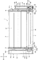
次に、第5実施形態について、図10〜図12を参照して説明する。本実施形態では、第2ヘッダタンク6に対して収容容器30を着脱可能に構成している点が第1実施形態と相違している。
Fifth Embodiment
Next, a fifth embodiment will be described with reference to FIGS. The present embodiment differs from the first embodiment in that the
図10に示すように、本実施形態の第2ヘッダタンク6には、中央の内部空間61bを形成する部位に、タンク側嵌合部63が設けられている。タンク側嵌合部63は、収容容器30側に突出しており、その先端部分が、後述する収容容器30の中間嵌合受部316に嵌合するように構成されている。
As shown in FIG. 10, in the
また、第2ヘッダタンク6には、下方の内部空間61cを形成する部位に、タンク側嵌合受部64が設けられている。タンク側嵌合受部64は、収容容器30側に突出しており、その先端部分が、後述する収容容器30の収容側連通部317と嵌合するように構成されている。
Further, the
続いて、本実施形態の収容容器30には、タンク側嵌合部63に対向する部位に、中間嵌合受部316が設けられている。中間嵌合受部316は、図11に示すように、タンク側嵌合部63に対して着脱可能に嵌合するように構成されている。
Subsequently, in the
また、収容容器30には、タンク側嵌合受部64に対向する部位に、収容側連通部317が設けられている。本実施形態の収容側連通部317は、図12に示すように、タンク側嵌合受部64に対して着脱可能に嵌合するように構成されている。また、収容側連通部317には、タンク側嵌合受部64との嵌合状態を解除する解除部材317aが設けられている。
Further, in the
その他の構成は、第1実施形態と同様である。本実施形態の構成によれば、第1実施形態と同様に、受液器10における幅方向の寸法を抑えて、薄幅な凝縮器1を実現することが可能となる。
The other configuration is the same as that of the first embodiment. According to the configuration of the present embodiment, as in the first embodiment, it is possible to realize the
さらに、本実施形態では、収容容器30を第2ヘッダタンク6に対して着脱可能に接続する構成としている。これによれば、第2ヘッダタンク6から収容容器30を着脱することで、容易にフィルタ35や乾燥剤36を交換することが可能となる。すなわち、凝縮器1の保守性の向上を図ることができる。
Furthermore, in the present embodiment, the
ここで、本実施形態では、図12において、タンク側嵌合受部64に対して収容側連通部317を嵌合するための具体的な構造を図示したが、タンク側嵌合受部64に対して収容側連通部317を着脱可能であれば、他の締結構造としてもよい。
Here, in the present embodiment, a specific structure for fitting the storage
(他の実施形態)
以上、本発明の実施形態について説明したが、本発明は上述の実施形態に限定されるものではなく、特許請求の範囲に記載した範囲内において適宜変更が可能である。例えば、以下のように種々変形可能である。
(Other embodiments)
As mentioned above, although embodiment of this invention was described, this invention is not limited to the above-mentioned embodiment, In the range described in the claim, it can change suitably. For example, various modifications are possible as follows.
(1)上述の各実施形態の如く、収容容器30と入口側コネクタ7とが干渉しないように、収容容器30の上端部が入口側コネクタ7よりも下方側に位置する構成が望ましいが、これに限定されない。収容容器30と入口側コネクタ7との干渉が、凝縮器1の体格に影響が殆どないような場合には、収容容器30の上端部が入口側コネクタ7よりも上方側に位置する構成としてもよい。
(1) As in the above-described embodiments, it is preferable that the upper end of the
(2)上述の各実施形態の如く、第2ヘッダタンク6における中間集合空間を形成する部位に、中間連結部311を介して収容容器30を接続する構成とすることが望ましいが、これに限定されない。例えば、第2ヘッダタンク6と収容容器30との間の熱移動が凝縮器1における放熱性能へ殆ど影響しないような場合には、第2ヘッダタンク6における入口側コネクタ7から冷媒が流入する空間を形成する部位に、収容容器30を接続する構成としてもよい。
(2) As in each of the above-described embodiments, it is preferable that the
(3)上述の各実施形態では、コア部2の凝縮部21として、冷媒の流れが左右に3回転向する例について説明したが、これに限定されない。凝縮部21は、冷媒の流れが左右に1、2回転向したり、冷媒の流れが左右に3回以上転向したりする構成としてもよい。
(3) In each of the above-described embodiments, an example is described in which the flow of the refrigerant is directed to the left and right as the
(4)上述の各実施形態では、コア部2の左側に受液器10を配置し、コア部2の右側に収容容器30を配置する例について説明したが、これに限定されない。例えば、凝縮器1は、コア部2の右側に受液器10を配置し、コア部2の左側に収容容器30を配置する構成としてもよい。
(4) In the above embodiments, the
(5)上述の各実施形態の如く、コア部2に対して過冷却部22を設けることが望ましいが、これに限定されず、過冷却部22が省略されていてもよい。
(5) As in the above-described embodiments, it is desirable to provide the
(6)上述の各実施形態の如く、隣接するチューブ2a間にフィン2bを配置することが望ましいが、これに限定されず、フィン2bが省略されていてもよい。
(6) Although it is desirable to arrange the
(7)上述の各実施形態では、本発明の凝縮器1を車両用の空調装置に適用される冷凍サイクルの凝縮器に適用する例について説明したが、これに限定されない。本発明の凝縮器1は、例えば、熱のこもり易い環境下に設置される据置型の凝縮器として用いることも可能である。
(7) Although the above-mentioned each embodiment demonstrated the example which applies the
(8)上述の実施形態において、実施形態を構成する要素は、特に必須であると明示した場合および原理的に明らかに必須であると考えられる場合等を除き、必ずしも必須のものではないことは言うまでもない。 (8) In the above-mentioned embodiment, the elements constituting the embodiment are not necessarily essential except when clearly indicated as being essential and when it is considered to be obviously essential in principle. Needless to say.
(9)上述の実施形態において、実施形態の構成要素の個数、数値、量、範囲等の数値が言及されている場合、特に必須であると明示した場合および原理的に明らかに特定の数に限定される場合等を除き、その特定の数に限定されない。 (9) In the above embodiment, when numerical values such as the number, numerical value, amount, range and the like of the constituent elements of the embodiment are mentioned, it is clearly indicated that they are particularly essential and clearly in principle specific numbers. It is not limited to that particular number except where limited.
(10)上述の実施形態において、構成要素等の形状、位置関係等に言及するときは、特に明示した場合および原理的に特定の形状、位置関係等に限定される場合等を除き、その形状、位置関係等に限定されない。 (10) In the above embodiment, when referring to the shapes, positional relationships, etc. of the components etc., unless specifically stated otherwise or in principle when limited to a specific shape, positional relationship, etc., the shapes It is not limited to the positional relationship etc.
1 凝縮器
2 コア部
21 凝縮部
5 第1ヘッダタンク
6 第2ヘッダタンク
10 受液器
30 収容容器
36 乾燥剤
DESCRIPTION OF
Claims (3)
前記チューブの積層方向に沿って延びると共に前記コア部における前記チューブの長手方向の一端側に接続される第1ヘッダタンク(5)と、
前記チューブの積層方向に沿って延びると共に前記コア部における前記チューブの長手方向の他端側に接続される第2ヘッダタンク(6)と、
前記チューブの積層方向に沿って延びると共に前記第1ヘッダタンクに隣接して配置され、前記第1ヘッダタンクの内部に連通する受液器(10)と、
水分を吸着する乾燥剤(36)と、
少なくとも前記乾燥剤を収容する収容容器(30)と、を備え、
前記収容容器は、前記第2ヘッダタンクに隣接して配置され、前記第2ヘッダタンクの内部に存する冷媒が流入するように、前記第2ヘッダタンクの内部に連通しており、
前記第2ヘッダタンクには、
前記コア部を構成する一部のチューブを通過した冷媒を集合させる中間集合空間(61b)と、
前記中間集合空間に集合した冷媒を残部のチューブの少なくとも一部へ分配する中間分配空間(61d)と、が形成されており、
前記中間集合空間および前記中間分配空間は、前記収容容器の内部空間を介して連通していることを特徴とする凝縮器。 A core portion (2) configured by vertically laminating a plurality of tubes (2a) through which the refrigerant flows, and emitting heat from the refrigerant by heat exchange with an external fluid flowing outside the tubes;
A first header tank (5) extending along the stacking direction of the tubes and connected to one end of the core portion in the longitudinal direction of the tubes;
A second header tank (6) extending along the stacking direction of the tubes and connected to the other end of the core portion in the longitudinal direction of the tubes;
A receiver (10) which extends along the stacking direction of the tubes and is disposed adjacent to the first header tank and in communication with the inside of the first header tank;
A desiccant (36) that absorbs moisture,
A container (30) for containing at least the desiccant.
The storage container is disposed adjacent to the second header tank, and is in communication with the inside of the second header tank so that the refrigerant existing inside the second header tank flows in,
In the second header tank,
An intermediate collecting space (61b) for collecting the refrigerant having passed through a part of the tubes constituting the core part;
An intermediate distribution space (61d) for distributing the refrigerant collected in the intermediate collection space to at least a part of the remaining tube;
A condenser characterized in that the intermediate collection space and the intermediate distribution space are in communication via an internal space of the storage container.
Priority Applications (1)
| Application Number | Priority Date | Filing Date | Title |
|---|---|---|---|
| JP2015106669A JP6500599B2 (en) | 2015-05-26 | 2015-05-26 | Condenser |
Applications Claiming Priority (1)
| Application Number | Priority Date | Filing Date | Title |
|---|---|---|---|
| JP2015106669A JP6500599B2 (en) | 2015-05-26 | 2015-05-26 | Condenser |
Publications (2)
| Publication Number | Publication Date |
|---|---|
| JP2016217682A JP2016217682A (en) | 2016-12-22 |
| JP6500599B2 true JP6500599B2 (en) | 2019-04-17 |
Family
ID=57580728
Family Applications (1)
| Application Number | Title | Priority Date | Filing Date |
|---|---|---|---|
| JP2015106669A Expired - Fee Related JP6500599B2 (en) | 2015-05-26 | 2015-05-26 | Condenser |
Country Status (1)
| Country | Link |
|---|---|
| JP (1) | JP6500599B2 (en) |
Families Citing this family (1)
| Publication number | Priority date | Publication date | Assignee | Title |
|---|---|---|---|---|
| WO2016190025A1 (en) * | 2015-05-26 | 2016-12-01 | 株式会社デンソー | Condenser |
Family Cites Families (8)
| Publication number | Priority date | Publication date | Assignee | Title |
|---|---|---|---|---|
| JP3081941B2 (en) * | 1990-08-23 | 2000-08-28 | 株式会社ゼクセル | Receiver tank integrated condenser |
| JPH0612127U (en) * | 1992-03-30 | 1994-02-15 | カルソニック株式会社 | Automotive air conditioner capacitors |
| JPH1096570A (en) * | 1996-07-29 | 1998-04-14 | Showa Alum Corp | Liquid receptor integrated condenser |
| JP2000018772A (en) * | 1998-06-23 | 2000-01-18 | Showa Alum Corp | Condenser with receiver tank |
| JP2002147895A (en) * | 2000-11-08 | 2002-05-22 | Toyo Radiator Co Ltd | Condenser equipped with receiver |
| DE10100423A1 (en) * | 2001-01-08 | 2002-07-11 | Valeo Klimasysteme Gmbh | Mixing chamber for a motor vehicle air conditioning condenser that minimizes two-way influence on the flow, eddy formation, bubble generation and that maintains a constant temperature gradient |
| KR100805429B1 (en) * | 2001-09-19 | 2008-02-20 | 한라공조주식회사 | Condenser |
| KR100799551B1 (en) * | 2001-12-28 | 2008-01-31 | 한라공조주식회사 | Condenser with integral liquid reservoir |
-
2015
- 2015-05-26 JP JP2015106669A patent/JP6500599B2/en not_active Expired - Fee Related
Also Published As
| Publication number | Publication date |
|---|---|
| JP2016217682A (en) | 2016-12-22 |
Similar Documents
| Publication | Publication Date | Title |
|---|---|---|
| US9791190B2 (en) | Condenser | |
| US20060254310A1 (en) | Apparatus for cooling air-conditioning refrigerant | |
| JP4052706B2 (en) | Subcool system capacitor | |
| JP6428934B2 (en) | Condenser | |
| JP6358167B2 (en) | Condenser | |
| US8991479B2 (en) | Condenser | |
| JP6500599B2 (en) | Condenser | |
| TW200303973A (en) | Heat exchanger with receiver tank, receiver tank connecting member, receiver tank mounting structure of heat exchanger and refrigeration system | |
| JP2007078292A (en) | Heat exchanger, and dual type heat exchanger | |
| JP2008267753A (en) | Heat exchanger | |
| JP5622411B2 (en) | Capacitor | |
| JP5746872B2 (en) | Capacitor | |
| JP2010065880A (en) | Condenser | |
| JP2017172866A (en) | Condenser | |
| JP6460233B2 (en) | Condenser | |
| JP6406127B2 (en) | Condenser | |
| JP5753694B2 (en) | Capacitor | |
| JP2013029257A (en) | Condenser | |
| JPH11211277A (en) | Subcool system condenser | |
| JP2018076983A (en) | Condenser | |
| JP5604140B2 (en) | Capacitor | |
| JP2018076975A (en) | Condenser | |
| JP2017083023A (en) | Condenser | |
| EP1278030B1 (en) | Heat exchanger | |
| JP2017172865A (en) | Condenser |
Legal Events
| Date | Code | Title | Description |
|---|---|---|---|
| A621 | Written request for application examination |
Free format text: JAPANESE INTERMEDIATE CODE: A621 Effective date: 20170804 |
|
| A977 | Report on retrieval |
Free format text: JAPANESE INTERMEDIATE CODE: A971007 Effective date: 20180510 |
|
| A131 | Notification of reasons for refusal |
Free format text: JAPANESE INTERMEDIATE CODE: A131 Effective date: 20180515 |
|
| A521 | Request for written amendment filed |
Free format text: JAPANESE INTERMEDIATE CODE: A523 Effective date: 20180622 |
|
| A131 | Notification of reasons for refusal |
Free format text: JAPANESE INTERMEDIATE CODE: A131 Effective date: 20180821 |
|
| A521 | Request for written amendment filed |
Free format text: JAPANESE INTERMEDIATE CODE: A523 Effective date: 20181003 |
|
| A02 | Decision of refusal |
Free format text: JAPANESE INTERMEDIATE CODE: A02 Effective date: 20181211 |
|
| A521 | Request for written amendment filed |
Free format text: JAPANESE INTERMEDIATE CODE: A523 Effective date: 20190128 |
|
| A911 | Transfer to examiner for re-examination before appeal (zenchi) |
Free format text: JAPANESE INTERMEDIATE CODE: A911 Effective date: 20190201 |
|
| TRDD | Decision of grant or rejection written | ||
| A01 | Written decision to grant a patent or to grant a registration (utility model) |
Free format text: JAPANESE INTERMEDIATE CODE: A01 Effective date: 20190219 |
|
| A61 | First payment of annual fees (during grant procedure) |
Free format text: JAPANESE INTERMEDIATE CODE: A61 Effective date: 20190304 |
|
| R151 | Written notification of patent or utility model registration |
Ref document number: 6500599 Country of ref document: JP Free format text: JAPANESE INTERMEDIATE CODE: R151 |
|
| LAPS | Cancellation because of no payment of annual fees |