JP6498913B2 - Vehicle seat - Google Patents
Vehicle seat Download PDFInfo
- Publication number
- JP6498913B2 JP6498913B2 JP2014229256A JP2014229256A JP6498913B2 JP 6498913 B2 JP6498913 B2 JP 6498913B2 JP 2014229256 A JP2014229256 A JP 2014229256A JP 2014229256 A JP2014229256 A JP 2014229256A JP 6498913 B2 JP6498913 B2 JP 6498913B2
- Authority
- JP
- Japan
- Prior art keywords
- seat
- vehicle
- width direction
- cushion
- leg
- Prior art date
- Legal status (The legal status is an assumption and is not a legal conclusion. Google has not performed a legal analysis and makes no representation as to the accuracy of the status listed.)
- Active
Links
- 230000033001 locomotion Effects 0.000 claims description 13
- 238000010586 diagram Methods 0.000 description 4
- 239000002184 metal Substances 0.000 description 4
- 230000002093 peripheral effect Effects 0.000 description 3
- 230000003014 reinforcing effect Effects 0.000 description 3
- 239000011347 resin Substances 0.000 description 2
- 229920005989 resin Polymers 0.000 description 2
- 238000009434 installation Methods 0.000 description 1
- 230000009545 invasion Effects 0.000 description 1
- 239000000463 material Substances 0.000 description 1
- 230000001105 regulatory effect Effects 0.000 description 1
- 230000002787 reinforcement Effects 0.000 description 1
- 230000000452 restraining effect Effects 0.000 description 1
Images


Description
本発明は、車両用シートに係り、特に、シートバック及びシートクッションを車体フロアよりも低位置に収納可能な車両用シートに関する。 The present invention relates to a vehicle seat, and more particularly to a vehicle seat capable of storing a seat back and a seat cushion at a position lower than a vehicle body floor.
従来、シート本体を構成するシートバック及びシートクッションを車体フロアよりも低位置に収納可能な車両用シートは既に知られており、その中には、シート本体を前倒れさせてシート前方に設けられた収納フロアに収納可能な車両用リアシートが存在する(例えば、特許文献1参照)。 Conventionally, there are already known vehicle seats in which the seat back and the seat cushion constituting the seat body can be stored at a position lower than the vehicle floor, and among them, the seat body is tilted forward and provided in front of the seat. There is a vehicle rear seat that can be stored on a storage floor (see, for example, Patent Document 1).
特許文献1に記載の車両シートは、車体フロアに取り付けられ、シートバックを回動可能に支持する取り付け軸と、上端がシートクッションの前方部分を支持し、下端が収納フロアに固定された保持溝に回動可能に保持される脚部材と、からなる収納構造を備えている。
シート本体の収納操作時には、シートバックが車体フロアに対してシートクッションを収納フロアへ移動させるように回転し、脚部材がシートバックと連動して保持溝を中心として回転することで、シート本体を収納フロアに収納可能な構成となっている。
また、車両シートは、乗員が着座可能な使用状態から、脚部材を保持溝から離脱させた上で、シートクッションを上方に跳ね上げたチップアップ状態へ切り替え可能な構成となっている。
A vehicle seat described in
When the seat body is retracted, the seat back rotates relative to the vehicle floor to move the seat cushion to the storage floor, and the leg member rotates around the holding groove in conjunction with the seat back. It can be stored on the storage floor.
The vehicle seat can be switched from a use state in which an occupant can be seated to a tip-up state in which the seat member is lifted upward after the leg member is detached from the holding groove.
ところで、特許文献1のようなシート本体を収納可能なシートでは、シートバックを折り畳み可能に連結するためのリクライニング機構や、収納フロアに収納するための収納機構等を備えていることで複雑な構造となっている。そのため、構成部品の配置を工夫してシート全体の剛性を確保する必要がある。
一方で、車両内にシートを設置するにあたり、車両内部の形状や内装部品の設置スペースを考慮した配置レイアウトにすべく、シートクッションを基準位置としたときにシートバックをシート幅方向の一方側にずらして配置する等の工夫が求められることがある。
そこで、上記のようなシートでは、シート全体の剛性を確保しながらも、車両内の配置レイアウトまで配慮した設計が望まれていた。
By the way, in the seat which can store a seat body like
On the other hand, when installing the seat in the vehicle, the seat back should be on one side in the seat width direction when the seat cushion is used as the reference position in order to achieve a layout that takes into account the internal shape of the vehicle and the installation space for interior parts. Some ideas, such as shifting and arranging, may be required.
Therefore, the above-described seat has been desired to be designed in consideration of the layout in the vehicle while ensuring the rigidity of the entire seat.
また、特許文献1のようなシートでは、シートクッションを支持する脚部材が、シートクッションと収納フロアとの間で連結されるために長尺な部材となっていた。
そうすると、使用状態とチップアップ状態との切り替え操作で脚部材を保持溝から着脱させるときに、脚部材の全長が長いことで、離脱した脚部材の前後方向の振れ幅が大きくなってしまい、脚部材を保持溝に再装着させる操作が困難になっていた。
そこで、使用状態から切り替え操作が容易な車両用シートが望まれていた。
Further, in the seat as in
Then, when the leg member is detached from the holding groove by the switching operation between the use state and the tip-up state, the swinging width in the front-rear direction of the detached leg member is increased due to the long overall length of the leg member. The operation of reattaching the member to the holding groove has been difficult.
Therefore, a vehicle seat that can be easily switched from the state of use has been desired.
また、特許文献1のようなシートでは、シート本体を設置する車体フロア面だけでなく、収納フロア面にも収納構造の構成部品を取り付けており、シート本体を収納するために複雑な構造となっていた。
そのため、シンプルな構造で、収納フロアに収納可能な車両用シートが望まれていた。
Further, in the seat as in
Therefore, a vehicle seat that can be stored on a storage floor with a simple structure has been desired.
本発明は、上記の課題に鑑みてなされたものであり、本発明の目的は、シート全体の剛性を確保し、車両内の配置レイアウトまで配慮した車両用シートを提供することにある。
また、本発明の他の目的は、使用状態から切り替え操作が容易な車両用シートを提供することにある。
また、本発明の他の目的は、シンプルな構造で収納フロアに収納可能な車両用シートを提供することにある。
The present invention has been made in view of the above-described problems, and an object of the present invention is to provide a vehicle seat that ensures the rigidity of the entire seat and considers the layout in the vehicle.
Another object of the present invention is to provide a vehicle seat that can be easily switched from a use state.
Another object of the present invention is to provide a vehicle seat that can be stored on a storage floor with a simple structure.
前記課題は、本発明の車両用シートによれば、背もたれ部となるシートバックと、該シートバックに連結され、着座部となるシートクッションと、を有するシート本体を備え、乗員が着座可能な使用状態と、前記シート本体を前記使用状態から移動させた移動状態との間で切り替え可能な車両用シートであって、車体フロア側に取り付けられ、前記シート本体がシート前後方向に回動可能となるように該シート本体のシート前後方向の一端側に連結されるシート回動軸と、上端部が前記シート本体の他端側に取り付けられ、下端部が前記車体フロア側に設けられた脚保持部材に着脱可能に保持される着脱脚と、前記車体フロア側に設けられ、前記シート回動軸及び前記脚保持部材が取り付けられる支持ベースと、該支持ベース上に取り付けられ、前記着脱脚を前記脚保持部材に保持された状態でロック可能なロック装置と、を備え、前記シートバックの骨格となるバックフレームのシート幅方向の中心位置は、前記シートクッションの骨格となるクッションフレームの中心位置に対してシート幅方向の一方側にずれて配置され、前記支持ベースのシート幅方向の中心位置は、前記クッションフレームの中心位置に対して前記一方側にずれて配置され、前記ロック装置は、前記支持ベースの中心位置よりもシート幅方向の他方側に配置されていること、により解決される。 According to the vehicle seat of the present invention, the subject is provided with a seat body having a seat back serving as a backrest portion and a seat cushion coupled to the seat back and serving as a seating portion, and can be used by a passenger. and a state, wherein a sheet body and switchable vehicle seat between a moving state of moving from the use condition, attached to the vehicle body floor side, the seat body can rotate in the direction back and forth sheet and A seat rotation shaft coupled to one end side of the seat body in the longitudinal direction of the seat so that the upper end portion is attached to the other end side of the seat body, and a lower end portion is provided on the vehicle body floor side. A detachable leg that is detachably held by the member, a support base that is provided on the vehicle body floor side and to which the seat rotation shaft and the leg holding member are attached, and is mounted on the support base A locking device that can be locked in a state where the detachable leg is held by the leg holding member, and the center position in the seat width direction of the back frame that becomes the skeleton of the seat back becomes the skeleton of the seat cushion The center position of the support base is shifted to one side in the seat width direction with respect to the center position of the cushion frame, and the center position of the support base in the seat width direction is shifted to the one side with respect to the center position of the cushion frame, The locking device is solved by being arranged on the other side in the sheet width direction with respect to the center position of the support base.
上記の車両用シートでは、シートバックが、シートクッションに対してシート幅方向の一方側にずらして配置されているため、車両内の配置レイアウトを適宜配慮した車両用シートを実現できる。
そして、着脱脚の下端部分が従来のように収納フロアではなく、車体フロア側に配置されているため、着脱脚の全長を小さくできる。着脱脚の全長が小さい分だけ、着脱脚の前後方向の振れ幅が小さくなることから、着脱脚が脚保持部材に保持され易くなる。従って、使用状態から切り替え操作が一層容易になる。
そして、収納構造の構成部品を車体フロア側に全て配置するため、収納フロアに広い収納スペースを確保できる。
そして、支持ベースは、シートクッションに対して一方側にずらした位置にオフセット配置されるため、着座した乗員の荷重を効率良く受けることができる。
そして、ロック装置は、支持ベースの中心位置よりも、シート幅方向の他方側に配置されているため、オフセット配置によって空いたスペースを有効利用できる。
In the above vehicle seat, since the seat back is disposed so as to be shifted to one side in the seat width direction with respect to the seat cushion, a vehicle seat in which the layout in the vehicle is appropriately considered can be realized.
And since the lower end part of an attachment / detachment leg is arrange | positioned at the vehicle body floor side instead of a storage floor like before, the full length of an attachment / detachment leg can be made small. Since the swing width in the front-rear direction of the detachable leg is reduced by the small total length of the detachable leg, the detachable leg is easily held by the leg holding member. Therefore, the switching operation from the use state becomes easier.
And since all the components of the storage structure are arranged on the vehicle body floor side, a large storage space can be secured on the storage floor.
And since a support base is offset-arranged in the position shifted to the one side with respect to the seat cushion, it can receive the load of the seated passenger | crew efficiently.
And since the locking device is arrange | positioned rather than the center position of the support base in the other side of a sheet | seat width direction, the vacant space by offset arrangement | positioning can be used effectively.
また前記課題は、本発明の車両用シートによれば、背もたれ部となるシートバックと、該シートバックに連結され、着座部となるシートクッションと、を有するシート本体を備え、乗員が着座可能な使用状態と、前記シート本体を前記使用状態から移動させた移動状態との間で切り替え可能な車両用シートであって、車体フロア側に取り付けられ、前記シート本体がシート前後方向に回動可能となるように該シート本体のシート前後方向の一端側に連結されるシート回動軸と、前記車体フロア側に設けられ、前記シート回動軸が取り付けられる支持ベースと、前記車両用シートにおいてシート幅方向の他方側に配置され、前記支持ベースに対して前記シート本体を前記シート回動軸を中心として回動可能に連結するリクライニング装置と、を備え、前記シートバックの骨格となるバックフレームのシート幅方向の中心位置は、前記シートクッションの骨格となるクッションフレームの中心位置に対してシート幅方向の一方側にずれて配置され、前記支持ベースのシート幅方向の中心位置は、前記クッションフレームの中心位置に対して前記一方側にずれて配置され、前記リクライニング装置は、前記支持ベースの中心位置よりもシート幅方向の他方側に配置されていること、によっても解決される。
上記の車両用シートでは、シートバックが、シートクッションに対してシート幅方向の一方側にずらして配置されているため、車両内の配置レイアウトを適宜配慮した車両用シートを実現できる。
そして、支持ベースは、シートクッションに対して一方側にずらした位置にオフセット配置されるため、着座した乗員の荷重を効率良く受けることができる。
そして、リクライニング装置は、支持ベースの中心位置よりも、シート幅方向の他方側に配置されているため、オフセット配置によって空いたスペースを有効利用できる。
Further, according to the vehicle seat of the present invention, the vehicle seat of the present invention includes a seat body having a seat back serving as a backrest portion and a seat cushion coupled to the seat back and serving as a seating portion, so that a passenger can be seated. and use, the sheet body a switchable vehicle seat between a moving state of moving from the use condition, attached to the vehicle body floor side, the seat body can rotate in the direction back and forth sheet A seat pivot shaft connected to one end side of the seat body in the front-rear direction of the seat body, a support base provided on the vehicle body floor side to which the seat pivot shaft is attached, and a seat in the vehicle seat A reclining device that is disposed on the other side in the width direction and connects the seat body to the support base so as to be rotatable about the seat rotation axis. The center position in the seat width direction of the back frame serving as the skeleton of the seat back is shifted to one side in the seat width direction with respect to the center position of the cushion frame serving as the skeleton of the seat cushion, and the support base The center position in the seat width direction is shifted to the one side with respect to the center position of the cushion frame, and the reclining device is disposed on the other side in the seat width direction from the center position of the support base. Is also solved.
In the above vehicle seat, since the seat back is disposed so as to be shifted to one side in the seat width direction with respect to the seat cushion, a vehicle seat in which the layout in the vehicle is appropriately considered can be realized.
And since a support base is offset-arranged in the position shifted to the one side with respect to the seat cushion, it can receive the load of the seated passenger | crew efficiently.
And since the reclining apparatus is arrange | positioned in the other side of the sheet | seat width direction rather than the center position of a support base, the space vacated by offset arrangement | positioning can be used effectively.
このとき、上端部が前記シート本体の他端側に取り付けられ、下端部が前記車体フロア側に設けられた脚保持部材に着脱可能に保持される着脱脚を備え、前記支持ベースには、前記シート回動軸及び前記脚保持部材が取り付けられると良い。 At this time, an upper end portion is attached to the other end side of the seat body, and a lower end portion is provided with a detachable leg that is detachably held by a leg holding member provided on the vehicle body floor side. A seat rotation shaft and the leg holding member may be attached .
このとき、前記支持ベースを上方から覆い、前記シート本体と共に移動する前記着脱脚をガイドするベースカバーを備え、前記シートクッションの左右側方部分において前記一方側の側方部分が、前記ベースカバーと上下に重なる位置に配置されていると良い。
上記のように、ベースカバーが、シート本体と共に移動する着脱脚をガイドしているため、既存の構成部品を利用して、使用状態から切り替え操作が容易な車両用シートを実現できる。
そして、シートクッションの左右側方部分において一方側の側方部分が、ベースカバーと上下に重なる位置に配置されているため、シート幅方向のシート大型化を抑制できる。
At this time, a base cover that covers the support base from above and guides the detachable leg that moves together with the seat body is provided, and the side portion on one side of the left and right side portions of the seat cushion is the base cover. It is good to arrange in the position which overlaps up and down.
As described above, since the base cover guides the detachable leg that moves together with the seat body, a vehicle seat that can be easily switched from the use state can be realized by using existing components.
And since the side part of one side is arrange | positioned in the position which overlaps with a base cover up and down in the right-and-left side part of a seat cushion, the seat enlargement of a seat width direction can be suppressed.
このとき、前記移動状態とは、前記シート本体を前記車体フロアよりも低位置に移動させた収納状態であって、前記車両用シートを車体フロア上に連結させるためのフロア連結部材を備え、前記フロア連結部材のシート幅方向の中心位置は、前記クッションフレームの中心位置に対して前記一方側にずれて配置されていると良い。
上記構成により、フロア連結部材が、シートクッションを基準位置にしたときにシートバックをずらした側と同じ側にずらしてオフセット配置されているため、着座した乗員の荷重を効率良く受けることができ、シート全体の剛性を確保できる。
そして、シート本体を使用状態と収納状態との間で移動させるときに、切り替え操作が良好になる。
At this time, the movement state is a storage state in which the seat body is moved to a position lower than the vehicle body floor, and includes a floor connecting member for connecting the vehicle seat on the vehicle body floor, The center position of the floor connecting member in the seat width direction may be arranged so as to be shifted to the one side with respect to the center position of the cushion frame .
With the above configuration, since the floor connecting member is offset and shifted to the same side as the side where the seat back is shifted when the seat cushion is set to the reference position, it can efficiently receive the load of the seated occupant, The rigidity of the entire sheet can be secured.
When the seat body is moved between the use state and the storage state, the switching operation is improved.
このとき、前記車両用シートにおいてシート幅方向の他方側に配置され、前記支持ベースに対して前記シート本体を前記シート回動軸を中心として回動可能に連結するリクライニング装置を備え、前記フロア連結部材の少なくとも一部が、前記リクライニング装置と、前記支持ベースの後端部分とのシート前後方向の間に配置されていると良い。
上記構成により、リクライニング装置及びその周辺部分の支持剛性を高められる。
At this time, the vehicle seat includes a reclining device that is disposed on the other side in the seat width direction and connects the seat body to the support base so as to be rotatable about the seat rotation axis. At least a part of the member may be disposed between the reclining device and the rear end portion of the support base in the seat front-rear direction .
With the above configuration, the support rigidity of the reclining device and its peripheral portion can be increased.
このとき、前記リクライニング装置は、前記支持ベース上に取り付けられ、前記シートバックの下端部と前記リクライニング装置とを連結する連結ブラケットと、該連結ブラケットを外側から覆うブラケットカバーと、を備えていると良い。
上記ブラケットカバーによって、リクライニング装置及びその周辺部分において外部の衝撃から保護することや、異物の侵入を防止できる。
At this time, the reclining device is mounted on the support base, and includes a connection bracket that connects the lower end portion of the seat back and the reclining device, and a bracket cover that covers the connection bracket from the outside. good.
The bracket cover can protect the reclining device and its peripheral portion from external impacts, and prevent foreign matter from entering.
このとき、前記リクライニング装置は、前記シートバックをロックしたロック状態と、ロック解除した状態との間で切り替えるための操作レバーを備え、該操作レバーは、前記シートバックにおいてシート幅方向の他方側に配置されていると良い。
上記構成により、オフセット配置によって空いたスペースを有効利用できる。
At this time, the reclining device includes an operation lever for switching between the locked state in which the seat back is locked and the unlocked state, and the operating lever is provided on the other side of the seat back in the seat width direction. It is good to be arranged.
With the above configuration, the space that is freed by the offset arrangement can be used effectively.
このとき、前記フロア連結部材は、前記車両用シートの左右側方位置に配置され、シート幅方向の他方側にある前記フロア連結部材は、前記一方側にある該フロア連結部材よりもシート幅方向の外側に張り出していると良い。
上記構成により、シートクッションを基準位置としたときにシートバックをシート幅方向の一方側にずらして配置している一方で、他方側にあるフロア連結部材がシート幅方向の外側に張り出しているため、結果的にシートが安定して車体フロア上に取り付けられる。
At this time, the floor connecting member is disposed at the left and right side positions of the vehicle seat, and the floor connecting member on the other side in the seat width direction is wider than the floor connecting member on the one side in the seat width direction. It should be overhanging outside.
With the above configuration, when the seat cushion is set to the reference position, the seat back is shifted to one side in the seat width direction, while the floor connecting member on the other side protrudes outside in the seat width direction. As a result, the seat is stably mounted on the vehicle body floor.
このとき、前記車体フロア上に固定され、シート前後方向に延びる左右のロアレールと、該ロアレールに沿って摺動可能に支持される左右のアッパレールと、該アッパレールを前記ロアレールに支持された状態でロック可能なレールロック装置と、を備え、該レールロック装置は、前記アッパレールをロックしたロック状態と、ロック解除した状態との間で切り替えるための操作ストラップを有し、該操作ストラップは、前記支持ベース上においてシート幅方向の他方側に配置され、シート前方に向かって張り出すように延びていると良い。
上記のように、操作ストラップは、支持ベース上においてシート幅方向の他方側に配置されるため、オフセット配置によって空いたスペースを有効利用できる。
そして、操作ストラップは、シート前方に向かって張り出すように延びているため、着座した乗員が手に取り易い位置となる。
At this time, the left and right lower rails fixed on the vehicle body floor and extending in the front-rear direction of the seat, the left and right upper rails supported so as to be slidable along the lower rails, and the upper rails locked in the state supported by the lower rails. A rail lock device, the rail lock device having an operation strap for switching between a locked state in which the upper rail is locked and an unlocked state, and the operation strap is provided on the support base. It is preferable that it is disposed on the other side in the seat width direction and extends so as to protrude toward the front of the seat .
As described above, since the operation strap is disposed on the other side in the seat width direction on the support base, a space vacated by the offset arrangement can be effectively used.
Since the operation strap extends so as to protrude toward the front of the seat, the seated occupant can easily take the hand.
このとき、着座した乗員を拘束するシートベルトに設けられたタングプレートを装着するためのバックルを備え、該バックルは、前記シートバックよりもシート幅方向の外側に配置され、前記シートクッションに対してシート幅方向の一方側に配置されていると良い。
上記構成により、構成部品同士の干渉を抑制することができ、かつ、オフセット配置によって空いたスペースを有効利用できる。
At this time, a buckle for mounting a tongue plate provided on a seat belt for restraining a seated occupant is provided, and the buckle is disposed on the outer side in the seat width direction than the seat back, and is attached to the seat cushion. It is good to arrange on one side in the sheet width direction .
With the above configuration, interference between components can be suppressed, and a space vacated by the offset arrangement can be effectively used.
このとき、前記シートクッションのうち、少なくとも前記シートバックに連結された部分を挟み込むように覆う外側クッションカバーと内側クッションカバーと、着座した乗員の腕部を支持するアームレストと、を備え、該アームレストは、前記シートバックにおいて一方側の側方部分に配置されていると良い。
上記クッションカバーによって、当該連結された部分において外部の衝撃から保護することや、異物の侵入を防止できる。
そして、オフセット配置によって空いたスペースを利用してアームレストを可動させることができる。
At this time, the seat cushion includes an outer cushion cover and an inner cushion cover that cover at least a portion connected to the seat back, and an armrest that supports an arm portion of a seated occupant. In the seat back, it is preferable that the seat back is disposed on a side portion on one side.
By the cushion cover, it is possible to protect the connected portions from external impact and to prevent foreign matters from entering.
And an armrest can be moved using the space vacated by offset arrangement.
本発明によれば、車両内の配置レイアウトを適宜配慮した車両用シートを実現できる。また、着座した乗員の荷重を効率良く受けてシート全体の剛性を確保できる。
本発明によれば、シート本体を使用状態と収納状態との間で移動させるときに、切り替え操作が良好になる。また、収納フロアに広い収納スペースを確保できる。
本発明によれば、支持ベースのオフセット配置によって、着座した乗員の荷重を効率良く受けられる。また、オフセット配置によって空いたスペースを有効利用できる。
本発明によれば、既存の構成部品を利用して、使用状態から切り替え操作が容易な車両用シートを実現できる。また、シート幅方向のシート大型化を抑制できる。
本発明によれば、リクライニング装置及びその周辺の支持剛性を高められる。
本発明によれば、オフセット配置によって空いたスペースを有効利用できる。また、着座した乗員が操作ストラップを手に取り易い位置となる。
本発明によれば、リクライニング装置及びその周辺部分において外部の衝撃から保護することや、異物の侵入を防止できる。
本発明によれば、オフセット配置によって空いたスペースを有効利用できる。
本発明によれば、シートが安定して車体フロア上に取り付けられる。
本発明によれば、構成部品同士の干渉を抑制でき、かつ、オフセット配置によって空いたスペースを有効利用できる。
本発明によれば、当該連結された部分において外部の衝撃から保護することや、異物の侵入を防止できる。
本発明によれば、オフセット配置によって空いたスペースを利用してアームレストを可動できる。
ADVANTAGE OF THE INVENTION According to this invention, the vehicle seat which considered the arrangement layout in a vehicle suitably is realizable. Further, it is possible to efficiently receive the load of the seated occupant and ensure the rigidity of the entire seat.
According to the present invention, when the seat body is moved between the use state and the storage state, the switching operation is improved. In addition, a large storage space can be secured on the storage floor.
According to the present invention, the load of the seated occupant can be efficiently received by the offset arrangement of the support base. In addition, an empty space can be effectively used by the offset arrangement.
ADVANTAGE OF THE INVENTION According to this invention, the vehicle seat which switching operation is easy from a use state is realizable using an existing component. Moreover, the sheet size increase in the sheet width direction can be suppressed.
According to the present invention, the support rigidity of the reclining device and its periphery can be increased.
According to the present invention, it is possible to effectively use a space vacated by the offset arrangement. Further, the seated occupant can easily take the operation strap.
ADVANTAGE OF THE INVENTION According to this invention, it can protect from an external impact in a reclining apparatus and its peripheral part, and can prevent invasion of a foreign material.
According to the present invention, it is possible to effectively use a space vacated by the offset arrangement.
According to the present invention, the seat is stably mounted on the vehicle body floor.
According to the present invention, it is possible to suppress interference between components, and to effectively use a space vacated by an offset arrangement.
According to the present invention, it is possible to protect the connected portions from external impacts and to prevent foreign matters from entering.
According to the present invention, the armrest can be moved using the space that is vacated by the offset arrangement.
以下、本発明の実施形態に係る車両用シートについて、図1〜図10を参照しながら説明する。
本実施形態は、シート本体を収納フロアに収納可能な車両用シートであって、シート本体が回動可能となるように連結されるシート回動軸と、上端がシート本体に取り付けられ、下端が支持ベース上の脚保持部材に着脱可能に保持される着脱脚と、シートを車体フロア上に連結させるための左右のフロア連結部材とを備えており、シートバック及びフロア連結部材のシート幅方向の中心位置が、共にシートクッションの中心位置に対してシート幅方向の一方側にずれて配置されていることを特徴とする車両用シートの発明に関するものである。
なお、車両用シートのシートバックに対して乗員が着座する側がシート前方側となる。
Hereinafter, a vehicle seat according to an embodiment of the present invention will be described with reference to FIGS.
The present embodiment is a vehicle seat that can store a seat body on a storage floor, the seat pivot shaft connected so that the seat body can pivot, an upper end attached to the seat body, and a lower end A detachable leg that is detachably held by the leg holding member on the support base, and left and right floor connecting members for connecting the seat to the vehicle body floor, and the seat back and the floor connecting member in the seat width direction are provided. The present invention relates to an invention of a vehicle seat characterized in that the center position is shifted to one side in the seat width direction with respect to the center position of the seat cushion.
The side on which the occupant sits with respect to the seat back of the vehicle seat is the front side of the seat.
本実施形態の車両用シートSは、例えば車両の後部座席に相当するリアシートである。なお、車両前後方向に三列のシートを備える車両において二列目のミドルシートとしても利用可能である。
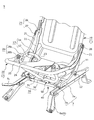
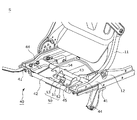
車両用シートSは、図1、図2に示すように、シートバック1と、シートクッション2と、ヘッドレスト3とを備えるシート本体と、車体フロア上にフロア連結部材6を介して取り付けられ、シート本体を前後移動可能に支持する図3の左右のレール装置7と、シート本体を下方から支持する着脱脚30と、レール装置7上に架設され、着脱脚30を下方から支持する支持ベース40と、支持ベース40上に取り付けられ、着脱脚30の下端を着脱可能に保持する脚保持部材50と、支持ベース40を上方から覆うベースカバー60と、から主に構成されている。
また、車両用シートSは、図2に示すように、支持ベース40に対してシートバック1をシート回動軸12を中心として回動可能に連結するリクライニング装置13と、シートバック1に対してシートクッション2を回動可能に連結するクッション回動装置25と、シートクッション2に対して着脱脚30を回動可能に連結する脚回動装置28と、を備えている。
車両用シートSのシート前方側には、図7に示すように、車体フロアよりも低位置に形成された凹型の収納フロアが設けられている。
The vehicle seat S of the present embodiment is a rear seat corresponding to a rear seat of the vehicle, for example. In addition, in a vehicle provided with three rows of seats in the vehicle longitudinal direction, it can be used as a second row of middle seats.
As shown in FIGS. 1 and 2, the vehicle seat S is attached to a seat body including a seat back 1, a
Further, as shown in FIG. 2, the vehicle seat S is connected to the
As shown in FIG. 7, a concave storage floor formed at a position lower than the vehicle body floor is provided on the front side of the vehicle seat S.
車両用シートSは、乗員が着座可能な使用状態と、シート本体を収納フロアに収納させた収納状態と、シート本体を上方に跳ね上げたチップアップ状態との3種類の形態のシートアレンジが可能なシートである。
具体的には、車両用シートSは、図7(a)に示す使用状態から、乗員が図1の操作レバー1cを引っ張ると、シート本体が前倒れして折り畳まれ、収納フロアに収納された図8(c)に示す収納状態に切り替わる。また、収納状態から、乗員が手動でシート本体を上方に起こすことで図9(b)に示すチップアップ状態に切り替わる。さらに、チップアップ状態から、乗員が操作部分として機能する着脱脚30を引っ張ると、シートバック1に対してシートクッション2がシート下方に回転し、図10(b)に示す使用状態に復帰する。詳細は後述する。
The vehicle seat S can be arranged in three types of seat arrangements: a use state in which an occupant can be seated, a storage state in which the seat body is stored on the storage floor, and a tip-up state in which the seat body is flipped upward. It is a sheet.
Specifically, when the occupant pulls the
シートバック1は、図1に示すように、乗員の背中を後方から支持する背もたれ部であって、骨格となる図2のバックフレーム10に、クッションパッド1aを載置して、表皮1bで被覆されて構成されている。シートバック1上面においてシート幅方向の右側には操作レバー1cが配置されている。
なお、シートバック1のシート幅方向の左側には、着座した乗員の腕部を支持するためのアームレスト4が取り付けられている。
As shown in FIG. 1, the seat back 1 is a backrest portion that supports the back of the occupant from the back, and the
On the left side of the seat back 1 in the seat width direction, an
シートクッション2は、図1に示すように、乗員を下方から支持する着座部であって、骨格となる図2のクッションフレーム20に、クッションパッド2aを載置して、クッションパッド2aの上から表皮2bによって被覆されて構成されている。
なお、シートクッション2の左側には、不図示のシートベルトに設けられたタングプレートを装着するためのバックル5が取り付けられている。
ヘッドレスト3は、乗員の頭を後方から支持する頭部であって、芯材となる不図示のピラーにクッションパッド3aを載置して表皮3bで被覆されて構成されている。
As shown in FIG. 1, the
A
The
フロア連結部材6は、図2、図3に示すように、シートの左右側方位置に配置されており、前方フロア連結部材6aと、後方フロア連結部材6bと、から主に構成されている。
前方フロア連結部材6aは、湾曲形状のプレート体からなり、図3に示すように、左右のロアレール7aの前方部分に一端が重ね合わされてボルト締結され、他端がシート前方に延びて車体フロア上にボルト締結されている。
右側の前方フロア連結部材6aは、シート幅方向の外側にやや張り出すようにしてシート前方に延びており、左側の前方フロア連結部材6aよりもシート幅方向の外側に傾斜して配置されている。
As shown in FIGS. 2 and 3, the
The front
The right front
後方フロア連結部材6bは、図2に示すように、平板形状のプレート体からなり、左右のロアレール7aの後方部分に一端が取り付けられ、他端がシート幅方向の外側に延びて車体フロア上にボルト締結されている。
後方フロア連結部材6bは、リクライニング装置13と、支持ベース40の後端部分との前後方向の間に配置されている。
As shown in FIG. 2, the rear
The rear
レール装置7は、上下方向においてシート本体と車体フロアとの間に配設されており、図3に示すように、車体フロア上にフロア連結部材6を介して固定され、シート前後方向に延びる左右のロアレール7aと、ロアレール7aに沿って摺動可能に支持される左右のアッパレール7bと、から主に構成されている。
左右のアッパレール7bの上面には支持ベース40が架設されており、支持ベース40上には、アッパレール7bをロアレール7aに支持された状態でロック可能な不図示のレールロック装置が取り付けられている。
当該レールロック装置は、アッパレール7bをロックしたロック状態と、ロック解除した状態との間で切り替えるための操作ストラップ7cを備えている。
操作ストラップ7cは、シート幅方向の右側に配置され、シート前方に向かって張り出すように延びている。
The
A
The rail lock device includes an
The
バックフレーム10は、シートバック1の骨格となる略矩形状の枠状体からなり、図3に示すように、バックフレーム10の左右外側面であって下方部分には、支持ベース40と連結するための左右の連結ブラケット11が取り付けられている。
連結ブラケット11は、上下方向に延出する略弓形状の板金部材からなり、連結ブラケット11の上端がバックフレーム10に取り付けられ、その下端が支持ベース40に取り付けられている。なお、連結ブラケット11の左右外側には、樹脂製のブラケットカバー11aが取り付けられている。
左側の連結ブラケット11の下端には、左右方向において支持ベース40に軸支されたシート回動軸12が設けられ、右側の連結ブラケット11の下端部には、支持ベース40に対してバックフレーム10を回動可能に連結するリクライニング装置13が取り付けられている。
The
The
A
リクライニング装置13は、公知の装置からなり、図3に示すように、連結ブラケット11の左右内側面に配置されており、左右方向においてクッションフレーム20との干渉を抑制している。
リクライニング装置13は、シート回動軸12と、バックフレーム10をシート回動軸12を中心として前方側に回転させて収納状態に付勢する渦巻きバネ14と、から主に構成されている。
シート回動軸12は、左右方向においてバックフレーム10側と支持ベース40側とに軸支され、渦巻きバネ14は、その一端がバックフレーム10側に係止され、他端が支持ベース40側に係止されている。
リクライニング装置13は、バックフレーム10の回動動作をロックするロック状態に切り替え可能であって、バックフレーム10を図1の起立姿勢にロックし、操作レバー1cが操作されることでロック状態を解除し、渦巻きバネ14の付勢力によってバックフレーム10を前方側に回転させて車体フロア側に折り畳むことができる。
As shown in FIG. 3, the
The
The
The
クッションフレーム20は、シートクッション2の骨格となる略矩形状の枠状体からなり、図3に示すように、左右側方に配置されたサイドフレーム21と、各サイドフレーム21の前方部分を連結する前方連結パイプ22と、各サイドフレームの前後方向の中央部分を連結する中央連結パイプ23と、前方連結パイプ22と中央連結パイプ23を連結する板状フレームとしてのパンフレーム24と、から主に構成されている。
The
サイドフレーム21は、シート前後方向に延出する板金部材からなり、その前方部分が前方連結パイプ22と連結され、その後端部分には、バックフレーム10に対してクッションフレーム20を回動可能に連結するクッション回動装置25が取り付けられている。
なお、サイドフレーム21の後方部分には、図2に示すように、サイドフレーム21を囲むように覆う縦断面コ字形状の外側クッションカバー21aと内側クッションカバー21bとが取り付けられている。
前方連結パイプ22は、コ字形状のパイプ部材からなり、その左右内側面には、クッションフレーム20に対して着脱脚30を回動可能に連結する脚回動装置28が取り付けられている。
The
As shown in FIG. 2, an outer cushion cover 21 a and an
The
クッション回動装置25は、公知の装置からなり、図3に示すように、クッション回動軸26と、クッションフレーム20をクッション回動軸26を中心として下方側に付勢する渦巻きバネ27と、を備えている。
クッション回動軸26は、左右方向においてバックフレーム10側とクッションフレーム20側とに軸支され、渦巻きバネ27は、その一端がバックフレーム10側に係止され、他端がクッションフレーム20側に係止されている。
クッション回動装置25は、クッションフレーム20の回動動作をロックするロック状態に切り替え可能である。
クッション回動装置25は、図8(c)に示すように、シート本体を収納フロアに収納させたときに、具体的には、バックフレーム10をクッションフレーム20側に折り畳んだ状態のときに、クッションフレーム20の回動動作をロックする。そして、図10(a)に示すように、操作レバーとして機能する着脱脚30が引っ張られるとロック状態を解除し、渦巻きバネ27の付勢力によってバックフレーム10に対してクッションフレーム20を下方側に回転させることができる。
The
The
The
As shown in FIG. 8C, the
脚回動装置28は、脚回動軸28aと、着脱脚30を脚回動軸28aを中心としてクッションフレーム20とは逆側に、言い換えれば、クッションフレーム20から離れる方向に付勢するバネ部材28bと、を備えている。
脚回動軸28aは、左右方向において前方連結パイプ22と、着脱脚30の上端部とに軸支され、バネ部材28bは、その一端がクッションフレーム20側に係止され、他端が着脱脚30側に係止されている。
脚回動装置28は、着脱脚30の回動動作をロックするロック状態に切り替え可能であって、図8(a)に示すように、着脱脚30が脚保持部材50から離脱し、クッションフレーム20側に収納されたときに、着脱脚30の回動動作をロックする。そして、図10(a)に示すように、ロックされた着脱脚30が引っ張られるとロック状態を解除し、バネ部材28bの付勢力によって、使用状態に復帰させるように着脱脚30を脚保持部材50に装着可能な位置に移動させることができる。
The
The
The
着脱脚30は、図3に示すように、シートクッション2を支持する略コ字形状のパイプ部材であり、左右側方に配置された脚本体部31と、各脚本体部31の下端を連結する脚連結部32と、を備えている。
脚本体部31の上端は、クッションフレーム20の前後方向の略中央部分において左右内側面に連結されており、脚連結部32の左右方向の略中央部は、脚保持部材50に着脱可能に保持されている。
着脱脚30の上端部は、着脱脚30の下端部よりもシート前方に張り出しており、着脱脚30の下端部から着脱脚30の上端部に向かって前方に上方傾斜している。
As shown in FIG. 3, the
The upper end of the leg
The upper end portion of the
支持ベース40は、シート本体を支持する部材であり、図5に示すように、左右側方にアッパレール7bに沿って配置された左右のサイドベース部41と、各サイドベース部41の前方部分を連結する第1ベース連結部42と、各サイドベース部41の略中央部分を連結する第2ベース連結部43と、各サイドベース部41の上面に取り付けられる左右の補強ベース部44と、第1ベース連結部42及び第2ベース連結部43を連結し、脚保持部材50を支持する保持部材支持部45と、を備えている。
The
サイドベース部41、補強ベース部44は、図5に示すように、前後方向に長尺な略クランク形状の板金部材からなり、サイドベース部41はアッパレール7b上面に連結され、補強ベース部44はサイドベース部41と上下で重なり合って閉断面構造を形成している。
第1ベース連結部42、第2ベース連結部43それぞれの左右両端は、サイドベース部41と補強ベース部44とで挟まれて連結されている。
保持部材支持部45は、脚保持部材50を支持する湾曲形状の板金部材であり、その前方部分は第1ベース連結部42に取り付けられ、その後方部分は第2ベース連結部43に取り付けられている。
As shown in FIG. 5, the
The left and right ends of each of the first
The holding
脚保持部材50は、図3、図5に示すように、着脱脚30を着脱可能に保持する略U字形状のクリップ部材からなり、その開口部分を前方斜め上方に向けた位置で保持部材支持部45に支持されている。
脚保持部材50は、一対の側壁部51と、各側壁部51の下端部を連結する底壁部52と、から構成されている。
各側壁部51は、その下端部から上端部に向かって互いに近接する方向に折り曲げられており、言い換えれば、脚保持部材50の開口部分を狭めるように開口部内側方向に折り曲げられており、その上端部には、開口部外側方向に反り曲げられたカール部53が形成されている。
一対のカール部53は、ベースカバー60に設けられた開口部を各々貫通し、着脱脚30側の外部に露出している。
As shown in FIGS. 3 and 5, the
The
Each
The pair of curled
脚保持部材50に隣接した部分には、車両の後面衝突時に着脱脚30の脚連結部32を脚保持部材50に保持させた状態でロックする慣性ロック装置54が配置される。
慣性ロック装置54は、ロック装置に相当し、支持ベース40に取り付けられており、シート前後方向において脚保持部材50と重なる位置に配置されている。
また慣性ロック装置54は、支持ベース40の中心位置よりも、シート幅方向の左側にある空いたスペースに配置されている。
An
The
The
ベースカバー60は、支持ベース40全体を上方から覆う樹脂成形品からなり、図4に示すように、シート前方側に配置される前方カバー61と、前方カバー61の後方に配置される後方カバーと、から構成されている。前方カバー61と後方カバーとはスナップフィット結合されている。
The
前方カバー61は、シート本体と共に移動する着脱脚30をガイドするガイド形状を備えている。
具体的には、前方カバー61は、着脱脚30を収容する脚収容凹部62と、脚収容凹部62よりもシート後方に配置され、着脱脚30が脚収容凹部62よりも後方に移動することを規制する脚移動規制部63と、脚収容凹部62よりもシート前方に配置され、シートクッション2の左側方部分と当接可能な当接部64と、を備えている。
The
Specifically, the
脚収容凹部62は、ベースカバー60上面の略中央部分から下方側に向かって窪んだ略U字形状の凹部からなり、その開口部分を前方斜め上方に向けた位置で配置されている。
脚収容凹部62の前後の側壁部には四角形状の開口部が形成されており、ベースカバー60裏面側から脚保持部材50の一部が、図1に示すように、当該開口部を介して外部に露出している。
また、後方の側壁部には、図4に示すように、上下に延びる開口部が形成されており、ベースカバー60裏面側から慣性ロック装置54の一部が、当該開口部を介して外部に露出している。
The
A rectangular opening is formed in the front and rear side walls of the
Further, as shown in FIG. 4, an opening extending vertically is formed in the rear side wall, and a part of the
脚移動規制部63は、図4に示すように、ベースカバー60上面の略中央部分からシート前方側に向かって張り出した部分からなり、脚収容凹部62の後方部分から連続して形成されている。
脚移動規制部63は、着脱脚30を脚収容凹部62に収容するときに、着脱脚30の後方移動を規制し、着脱脚30を脚収容凹部62側にガイドできる。
当接部64は、ベースカバー60上面から上方側に向かって突出する凸部からなり、シートクッション2の左側方部分と上下に重なる位置に配置されている。
As shown in FIG. 4, the leg
The leg
The
上記構成において、図4に示すように、シートバック1のシート幅方向の中心位置は、シートクッション2の中心位置に対してシート幅方向の左側にずらして配置されている。
そして一対のフロア連結部材6のシート幅方向の中心位置は、同様にシートクッション2の中心位置に対して左側にずらしてオフセット配置されている。
そのため、車両内の配置レイアウトを配慮しながらも、シートの剛性を確保したシートを実現することができる。
In the above configuration, as shown in FIG. 4, the center position of the seat back 1 in the seat width direction is shifted from the center position of the
The center position in the seat width direction of the pair of
Therefore, it is possible to realize a seat that ensures the rigidity of the seat while considering the layout in the vehicle.
また上記構成において、ヘッドレスト3のシート幅方向の中心位置は、シートクッション2の中心位置と略同じ位置に配置されている。
そのため、車両内の配置レイアウトにあまり影響を及ぼすことがないヘッドレスト3については、シートの剛性を優先した配置を設定できる。
Further, in the above configuration, the center position of the
Therefore, for the
また上記構成において、支持ベース40のシート幅方向の中心位置は、一対のフロア連結部材6の中心位置と略同じ位置となり、シートクッション2の中心位置に対して右側にずらしてオフセット配置されている。
そのため、着座した乗員の荷重を効率良く受けることができる。
In the above configuration, the center position of the
Therefore, the load of the seated occupant can be received efficiently.
<シート収納動作>
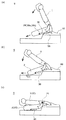
次に、図7、図8に基づいてシート本体を使用状態から収納状態へ移動させる動作を説明する。なお、図7、図8において、リクライニング装置13、クッション回動装置25、及び脚回動装置28は、黒丸で図示されるときにロック状態を示し、白丸で図示されるときにロック解除状態を示すものとする。図9、図10も同様である。
<Sheet storage operation>
Next, an operation for moving the sheet main body from the use state to the storage state will be described with reference to FIGS. 7 and 8, the
車両用シートSが図7(a)に示す使用状態にあるとき、シートバック1は、支持ベース40に支持され、リクライニング装置13によって起立姿勢にロックされており、シートバック1に連結されたシートクッション2は、脚保持部材50に保持された着脱脚30によって下方から支持されている。
When the vehicle seat S is in the use state shown in FIG. 7A, the seat back 1 is supported by the
車両用シートSを使用状態から収納状態へ移動させるときには、例えば、シートバック1上面に設けられた図1の操作レバー1cを操作する。
乗員が操作レバー1cを操作することで、図7(b)に示すように、リクライニング装置13のロック状態が解除され、シートバック1は、渦巻きバネ14の付勢力によって、シートクッション2を収納フロアまで移動させるようにシート回動軸12を中心としてシート前方側に回転を開始する。
着脱脚30は、シートバック1の回転に連動して、シートクッション2に対して脚回動軸28aを中心としてシートクッション2側に回転を開始する。このとき、着脱脚30は、シートクッション2と車体フロア側との間で突っ張った状態となるため、シートクッション2及びシートバック1を安定して移動させることができる。
なお、操作レバー1cとリクライニング装置13との間には、不図示の公知なケーブルが連結されており、操作レバー1cの操作によってケーブルが牽引され、ロック状態を解除する機構となっている。
When the vehicle seat S is moved from the use state to the storage state, for example, the
When the occupant operates the
The
Note that a known cable (not shown) is connected between the
シートバック1が、図8(a)に示すように、所定の回転位置に到達したときに、着脱脚30が脚保持部材50から離脱する。
離脱した着脱脚30は、ベースカバー60上面を乗り上げることで、バネ部材28bの付勢力に抗して脚回動軸28aを中心としてシートクッション2側に折り畳まれるように回転する。そして、着脱脚30は、所定の回転位置に到達したときに、脚回動装置28によってシートクッション2側に収納された状態でロックされる。
As shown in FIG. 8A, when the seat back 1 reaches a predetermined rotational position, the
The detached
さらに、シートバック1が、図8(b)に示すように、所定の回転位置に到達したときに、シートクッション2の前方部分が、着脱脚30よりも先に収納フロア面に当接する。
Further, as shown in FIG. 8B, when the seat back 1 reaches a predetermined rotational position, the front portion of the
上記一連の動作によって、図8(c)に示すように、シート本体が収納フロアに収納され、車両用シートSが収納状態に切り替わる。
シートクッション2は、収納状態のときに、具体的にはシートバック1がシートクッション2側に折り畳まれた状態のときに、クッション回動装置25によってロックされる。
着脱脚30は、収納状態のときに脚保持部材50よりも下方位置に配置される。
By the above series of operations, as shown in FIG. 8C, the seat body is stored on the storage floor, and the vehicle seat S is switched to the stored state.
The
The
<シートチップアップ動作>
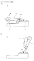
次に、図9に基づいてシート本体を収納状態からチップアップ状態へ移動させる動作を説明する。
車両用シートSが図9(a)に示す収納状態にあるときに、例えば、乗員が手動でシート本体を上方に起こすことで図9(b)に示すチップアップ状態に切り替わる。
このとき、クッション回動装置25がシートクッション2の回動動作をロックしているため、シートバック1を上方に起こすことでシートクッション2も一体的に上方に起こすことができる。
なお、チップアップ状態のときに、アッパレール7bをロアレール7aに対してシート後方側に摺動させることによって、シート前方側に広い荷室スペースを確保できる。
<Seat tip up operation>
Next, the operation of moving the seat body from the stored state to the tip-up state will be described with reference to FIG.
When the vehicle seat S is in the stored state shown in FIG. 9A, for example, the occupant manually raises the seat body to switch to the tip-up state shown in FIG. 9B.
At this time, since the
In the tip-up state, a large cargo space can be secured on the front side of the seat by sliding the
車両用シートSが図9(b)に示すチップアップ状態に切り替わったとき、シートバック1は、使用状態の位置と同じ位置に復帰し、リクライニング装置13によって起立姿勢でロックされることになる。
When the vehicle seat S is switched to the tip-up state shown in FIG. 9B, the seat back 1 returns to the same position as the position in the use state and is locked in the standing posture by the
<シート復帰動作>
次に、図10に基づいてシート本体をチップアップ状態から使用状態へ移動させる動作を説明する。
車両用シートSをチップアップ状態から使用状態へ移動させるときには、図10(a)に示すように、例えば操作部分として機能する着脱脚30を操作する。
乗員が着脱脚30を脚回動軸28aを中心として上方回転させるように、言い換えれば、シートクッション2側から離れる方向に引っ張ることで、クッション回動装置25及び脚回動装置28のロック状態が解除される。
なお、着脱脚30と、クッション回動装置25との間には、不図示の公知なケーブルが連結されており、着脱脚30の操作によってケーブルが引っ張られ、ロック状態を解除する構成となっている。
<Seat return operation>
Next, an operation for moving the seat body from the tip-up state to the use state will be described with reference to FIG.
When the vehicle seat S is moved from the tip-up state to the use state, as shown in FIG. 10A, for example, the
When the occupant pulls the
A known cable (not shown) is connected between the attachment /
シートクッション2は、クッション回動装置25の解除に伴い、図10(b)に示すように、渦巻きバネ27の付勢力によって、シートバック1に対して下方側に回転する。
着脱脚30は、脚回動装置28の解除に伴い、バネ部材28bの付勢力によって、脚保持部材50に装着可能な位置まで脚回動軸28aを中心として回転し、脚保持部材50に装着される。
このとき、着脱脚30は、ベースカバー60のうち、脚収容凹部62及び脚移動規制部63にガイドされることよって、脚収容凹部62の下端側に取り付けられた脚保持部材50に向かって移動するようになる。
上記一連の動作により、車両用シートSが図10(b)に示す使用状態に復帰する。
The
The attachment /
At this time, the
By the series of operations described above, the vehicle seat S returns to the use state shown in FIG.
<その他の実施形態>
上記実施形態において、車両用シートSのシート前方に収納フロアが形成されているが、特に限定されることなく、車両用シートSの後方に収納フロアが形成されていても良い。
その場合、シート回動軸12と着脱脚30とのシート前後方向の位置関係が逆の配置になることが望ましい。
また、収納状態の別実施例として、シートバック1が折り畳まれてシート本体がシート幅方向の一方側に跳ね上げ回転された状態を収納状態として想定しても良い。
<Other embodiments>
In the above embodiment, the storage floor is formed in front of the vehicle seat S, but the storage floor may be formed in the rear of the vehicle seat S without any particular limitation.
In that case, it is desirable that the positional relationship between the
As another example of the storage state, a state in which the seat back 1 is folded and the seat body is flipped up and rotated to one side in the seat width direction may be assumed as the storage state.
上記実施形態において、シート本体の収納状態が、特許請求の範囲の移動状態に相当するものとして説明されたが、特に限定されることなく、本実施形態のチップアップ状態等が移動状態に相当するものとしても良い。 In the above-described embodiment, the storage state of the seat main body has been described as corresponding to the movement state of the claims, but the tip-up state or the like of the present embodiment corresponds to the movement state without particular limitation. It is good as a thing.
上記実施形態において、図4に示すように、シートバック1及びフロア連結部材6のシート幅方向の中心位置は、共にシートクッション2の中心位置に対して左側にずれてオフセット配置されているが、右側にずれてオフセット配置されていても勿論良い。
In the above embodiment, as shown in FIG. 4, the center position in the seat width direction of the seat back 1 and the
上記実施形態において、図3に示すように、支持ベース40は、レール装置7を介して車体フロアに固定されているが、特に限定されることなく、レール装置7を不要として直接車体フロアに固定されていても良い。
また、連結ブラケット11を不要として、直接シートバック1と支持ベース40とをシート回動軸12を介して連結させていても良い。
In the above embodiment, as shown in FIG. 3, the
Further, the seat back 1 and the
上記実施形態では、具体例として自動車に用いられる収納可能な車両用シートについて説明したが、これに限定されることなく、電車、バス等の車両用シートのほか、飛行機、船等の乗物用シートとしても利用することができる。 In the above-described embodiment, a stowable vehicle seat used for an automobile has been described as a specific example. Can also be used.
本実施形態では、主として本発明に係る車両用シートSに関して説明した。
ただし、上記の実施形態は、本発明の理解を容易にするための一例に過ぎず、本発明を限定するものではない。本発明は、その趣旨を逸脱することなく、変更、改良され得ると共に、本発明にはその等価物が含まれることは勿論である。
In the present embodiment, the vehicle seat S according to the present invention has been mainly described.
However, said embodiment is only an example for making an understanding of this invention easy, and does not limit this invention. The present invention can be changed and improved without departing from the gist thereof, and the present invention includes the equivalents thereof.
S 車両用シート
1 シートバック
1a、2a、3a クッションパッド
1b、2b、3b 表皮
1c 操作レバー
2 シートクッション
3 ヘッドレスト
4 アームレスト
5 バックル
6 フロア連結部材
6a 前方フロア連結部材
6b 後方フロア連結部材
7 レール装置
7a ロアレール
7b アッパレール
7c 操作ストラップ
10 バックフレーム
11 連結ブラケット
11a ブラケットカバー
12 シート回動軸
13 リクライニング装置
14 渦巻きバネ
20 クッションフレーム
21 サイドフレーム
21a 外側クッションカバー
21b 内側クッションカバー
22 前方連結パイプ
23 中央連結パイプ
24 パンフレーム
25 クッション回動装置
26 クッション回動軸
27 渦巻きバネ
28 脚回動装置
28a 脚回動軸
28b バネ部材
30 着脱脚
31 脚本体部
32 脚連結部
40 支持ベース
41 サイドベース部
42 第1ベース連結部
43 第2ベース連結部
44 補強ベース部
45 保持部材支持部
50 脚保持部材
51 側壁部
52 底壁部
53 カール部
54 慣性ロック装置
60 ベースカバー
61 前方カバー
62 脚収容凹部
63 脚移動規制部
64 当接部
Claims (12)
乗員が着座可能な使用状態と、前記シート本体を前記使用状態から移動させた移動状態との間で切り替え可能な車両用シートであって、
車体フロア側に取り付けられ、前記シート本体がシート前後方向に回動可能となるように該シート本体のシート前後方向の一端側に連結されるシート回動軸と、
上端部が前記シート本体の他端側に取り付けられ、下端部が前記車体フロア側に設けられた脚保持部材に着脱可能に保持される着脱脚と、
前記車体フロア側に設けられ、前記シート回動軸及び前記脚保持部材が取り付けられる支持ベースと、
該支持ベース上に取り付けられ、前記着脱脚を前記脚保持部材に保持された状態でロック可能なロック装置と、を備え、
前記シートバックの骨格となるバックフレームのシート幅方向の中心位置は、前記シートクッションの骨格となるクッションフレームの中心位置に対してシート幅方向の一方側にずれて配置され、
前記支持ベースのシート幅方向の中心位置は、前記クッションフレームの中心位置に対して前記一方側にずれて配置され、
前記ロック装置は、前記支持ベースの中心位置よりもシート幅方向の他方側に配置されていることを特徴とする車両用シート。 A seat body having a seat back serving as a backrest and a seat cushion coupled to the seat back and serving as a seat;
A vehicle seat that is switchable between a use state in which an occupant can be seated and a movement state in which the seat body is moved from the use state,
Mounted on the car body floor side, and the seat pivot axis, wherein the seat body is connected to one end of the seat front-rear direction of the seat body so as to be rotatable in the direction back and forth sheet,
An detachable leg having an upper end attached to the other end of the seat body and a lower end removably held by a leg holding member provided on the vehicle body floor side;
A support base provided on the vehicle body floor side to which the seat rotation shaft and the leg holding member are attached;
A locking device mounted on the support base and capable of locking in a state where the detachable leg is held by the leg holding member,
The center position in the seat width direction of the back frame serving as the skeleton of the seat back is arranged to be shifted to one side in the seat width direction with respect to the center position of the cushion frame serving as the skeleton of the seat cushion.
The center position of the support base in the seat width direction is arranged to be shifted to the one side with respect to the center position of the cushion frame,
The vehicle seat according to claim 1, wherein the locking device is disposed on the other side in the seat width direction with respect to a center position of the support base.
乗員が着座可能な使用状態と、前記シート本体を前記使用状態から移動させた移動状態との間で切り替え可能な車両用シートであって、
車体フロア側に取り付けられ、前記シート本体がシート前後方向に回動可能となるように該シート本体のシート前後方向の一端側に連結されるシート回動軸と、
前記車体フロア側に設けられ、前記シート回動軸が取り付けられる支持ベースと、
前記車両用シートにおいてシート幅方向の他方側に配置され、前記支持ベースに対して前記シート本体を前記シート回動軸を中心として回動可能に連結するリクライニング装置と、を備え、
前記シートバックの骨格となるバックフレームのシート幅方向の中心位置は、前記シートクッションの骨格となるクッションフレームの中心位置に対してシート幅方向の一方側にずれて配置され、
前記支持ベースのシート幅方向の中心位置は、前記クッションフレームの中心位置に対して前記一方側にずれて配置され、
前記リクライニング装置は、前記支持ベースの中心位置よりもシート幅方向の他方側に配置されていることを特徴とする車両用シート。 A seat body having a seat back serving as a backrest and a seat cushion coupled to the seat back and serving as a seat;
A vehicle seat that is switchable between a use state in which an occupant can be seated and a movement state in which the seat body is moved from the use state,
Mounted on the car body floor side, and the seat pivot axis, wherein the seat body is connected to one end of the seat front-rear direction of the seat body so as to be rotatable in the direction back and forth sheet,
A support base provided on the vehicle body floor side to which the seat rotation shaft is attached;
A reclining device disposed on the other side in the seat width direction of the vehicle seat, and connecting the seat body to the support base so as to be rotatable about the seat rotation axis;
The center position in the seat width direction of the back frame serving as the skeleton of the seat back is arranged to be shifted to one side in the seat width direction with respect to the center position of the cushion frame serving as the skeleton of the seat cushion.
The center position of the support base in the seat width direction is arranged to be shifted to the one side with respect to the center position of the cushion frame,
The reclining device is arranged on the other side in the seat width direction with respect to the center position of the support base.
前記支持ベースには、前記シート回動軸及び前記脚保持部材が取り付けられることを特徴とする請求項2に記載の車両用シート。The vehicle seat according to claim 2, wherein the seat rotation shaft and the leg holding member are attached to the support base.
前記シートクッションの左右側方部分において前記一方側の側方部分が、前記ベースカバーと上下に重なる位置に配置されていることを特徴とする請求項1又は3に記載の車両用シート。 A base cover that covers the support base from above and guides the detachable leg that moves together with the seat body;
It said lateral portion of the one side in the left-right side portions of the seat cushion, the vehicle seat according to claim 1 or 3, characterized in that it is arranged at a position overlapping vertically with the base cover.
前記車両用シートを車体フロア上に連結させるためのフロア連結部材を備え、
前記フロア連結部材のシート幅方向の中心位置は、前記クッションフレームの中心位置に対して前記一方側にずれて配置されていることを特徴とする請求項1乃至4のいずれか1項に記載の車両用シート。 The movement state is a storage state in which the seat body is moved to a position lower than the vehicle body floor,
A floor connecting member for connecting the vehicle seat on the vehicle body floor;
Center position in the sheet width direction of the floor connecting member according to any one of claims 1 to 4, characterized in that it is arranged to be shifted to the one side with respect to the center position of the cushion frame Vehicle seat.
前記フロア連結部材の少なくとも一部が、前記リクライニング装置と、前記支持ベースの後端部分とのシート前後方向の間に配置されていることを特徴とする請求項5に記載の車両用シート。 A reclining device disposed on the other side in the seat width direction of the vehicle seat, and connected to the support base so as to be rotatable about the seat rotation axis;
The vehicle seat according to claim 5 , wherein at least a part of the floor connecting member is disposed between the reclining device and a rear end portion of the support base in a seat front-rear direction .
前記シートバックの下端部と前記リクライニング装置とを連結する連結ブラケットと、
該連結ブラケットを外側から覆うブラケットカバーと、を備えていることを特徴とする請求項6に記載の車両用シート。 The reclining device is mounted on the support base;
A connection bracket for connecting the lower end of the seat back and the reclining device;
The vehicle seat according to claim 6 , further comprising a bracket cover that covers the connecting bracket from the outside.
該操作レバーは、前記シートバックにおいてシート幅方向の他方側に配置されていることを特徴とする請求項6又は7に記載の車両用シート。 The reclining device includes an operation lever for switching between a locked state in which the seat back is locked and a unlocked state,
The vehicle seat according to claim 6 or 7 , wherein the operation lever is disposed on the other side in the seat width direction in the seat back.
シート幅方向の他方側にある前記フロア連結部材は、前記一方側にある該フロア連結部材よりもシート幅方向の外側に張り出していることを特徴とする請求項5乃至8のいずれか1項に記載の車両用シート。 The floor connecting member is disposed at the left and right side positions of the vehicle seat,
The floor connecting member on the other side of the sheet width direction, in any one of claims 5 to 8, characterized in that protrudes outside the seat width direction than the floor connecting member in the one side The vehicle seat as described.
該レールロック装置は、前記アッパレールをロックしたロック状態と、ロック解除した状態との間で切り替えるための操作ストラップを有し、
該操作ストラップは、前記支持ベース上においてシート幅方向の他方側に配置され、シート前方に向かって張り出すように延びていることを特徴とする請求項1乃至9のいずれか1項に記載の車両用シート。 Left and right lower rails fixed on the vehicle body floor and extending in the front-rear direction of the seat, left and right upper rails slidably supported along the lower rails, and rails that can be locked while the upper rails are supported by the lower rails A locking device,
The rail lock device has an operation strap for switching between a locked state in which the upper rail is locked and a unlocked state,
10. The operation strap according to claim 1, wherein the operation strap is disposed on the other side in the seat width direction on the support base and extends so as to protrude toward the front of the seat . Vehicle seat.
該バックルは、前記シートバックよりもシート幅方向の外側に配置され、前記シートクッションに対してシート幅方向の一方側に配置されていることを特徴とする請求項1乃至10のいずれか1項に記載の車両用シート。 With a buckle for attaching a tongue plate provided on the seat belt that restrains the seated occupant,
The said buckle is arrange | positioned on the outer side of a seat width direction rather than the said seat back, and is arrange | positioned with respect to the said seat cushion at the one side of a seat width direction. The vehicle seat described in 1.
着座した乗員の腕部を支持するアームレストと、を備え、
該アームレストは、前記シートバックにおいて一方側の側方部分に配置されていることを特徴とする請求項1乃至11のいずれか1項に記載の車両用シート。 An outer cushion cover and an inner cushion cover that cover the seat cushion so as to sandwich at least a portion connected to the seat back;
Comprising a armrest supporting the arm of the seated occupant, and
The vehicle seat according to any one of claims 1 to 11, wherein the armrest is disposed on a side portion on one side of the seat back.
Priority Applications (4)
| Application Number | Priority Date | Filing Date | Title |
|---|---|---|---|
| JP2014229256A JP6498913B2 (en) | 2014-11-11 | 2014-11-11 | Vehicle seat |
| CN201580061192.XA CN107107791B (en) | 2014-11-11 | 2015-11-10 | Vehicle seat |
| US15/525,801 US10427561B2 (en) | 2014-11-11 | 2015-11-10 | Vehicular seat |
| PCT/JP2015/081623 WO2016076318A1 (en) | 2014-11-11 | 2015-11-10 | Vehicular seat |
Applications Claiming Priority (1)
| Application Number | Priority Date | Filing Date | Title |
|---|---|---|---|
| JP2014229256A JP6498913B2 (en) | 2014-11-11 | 2014-11-11 | Vehicle seat |
Related Child Applications (1)
| Application Number | Title | Priority Date | Filing Date |
|---|---|---|---|
| JP2019047565A Division JP6708941B2 (en) | 2019-03-14 | 2019-03-14 | Vehicle seat |
Publications (2)
| Publication Number | Publication Date |
|---|---|
| JP2016088483A JP2016088483A (en) | 2016-05-23 |
| JP6498913B2 true JP6498913B2 (en) | 2019-04-10 |
Family
ID=56015804
Family Applications (1)
| Application Number | Title | Priority Date | Filing Date |
|---|---|---|---|
| JP2014229256A Active JP6498913B2 (en) | 2014-11-11 | 2014-11-11 | Vehicle seat |
Country Status (1)
| Country | Link |
|---|---|
| JP (1) | JP6498913B2 (en) |
Families Citing this family (1)
| Publication number | Priority date | Publication date | Assignee | Title |
|---|---|---|---|---|
| JP6654172B2 (en) | 2017-08-30 | 2020-02-26 | テイ・エス テック株式会社 | Vehicle seat |
Family Cites Families (7)
| Publication number | Priority date | Publication date | Assignee | Title |
|---|---|---|---|---|
| JPH0629106Y2 (en) * | 1989-01-23 | 1994-08-10 | デルタ工業株式会社 | Hinge structure of automobile seat |
| JP2511117Y2 (en) * | 1991-09-13 | 1996-09-18 | 株式会社タチエス | Shield cover structure of reclining device |
| JP2000103271A (en) * | 1998-09-30 | 2000-04-11 | Shiroki Corp | Inverted seat |
| JP4115953B2 (en) * | 2004-02-27 | 2008-07-09 | 本田技研工業株式会社 | Vehicle seat |
| JP2008105575A (en) * | 2006-10-26 | 2008-05-08 | Mazda Motor Corp | Rear chassis structure of vehicle |
| JP5690093B2 (en) * | 2010-07-29 | 2015-03-25 | ジョンソン コントロールズ テクノロジー カンパニーJohnson Controls Technology Company | Vehicle seat structure |
| WO2014168233A1 (en) * | 2013-04-12 | 2014-10-16 | 本田技研工業株式会社 | Vehicular seat device |
-
2014
- 2014-11-11 JP JP2014229256A patent/JP6498913B2/en active Active
Also Published As
| Publication number | Publication date |
|---|---|
| JP2016088483A (en) | 2016-05-23 |
Similar Documents
| Publication | Publication Date | Title |
|---|---|---|
| JP6262575B2 (en) | Vehicle seat | |
| US9789789B2 (en) | Vehicular seat | |
| WO2016076318A1 (en) | Vehicular seat | |
| JP6378052B2 (en) | Vehicle seat | |
| JP6524198B2 (en) | Vehicle seat | |
| JP2016088480A (en) | Vehicle seat | |
| JP6498913B2 (en) | Vehicle seat | |
| JP6347688B2 (en) | Vehicle seat | |
| JP6236233B2 (en) | Vehicle seat | |
| JP6490948B2 (en) | Vehicle seat | |
| JP2018062341A (en) | Vehicle seat | |
| JP6262451B2 (en) | Vehicle seat | |
| JP6708941B2 (en) | Vehicle seat | |
| JP6139652B2 (en) | Vehicle seat | |
| JP6646237B2 (en) | Vehicle seat | |
| JP6456107B2 (en) | Vehicle seat | |
| JP6708940B2 (en) | Vehicle seat | |
| JP6691308B2 (en) | Vehicle seat | |
| JP6263421B2 (en) | Vehicle seat | |
| JP7280499B2 (en) | vehicle seat | |
| JP2017154740A (en) | Vehicle seat | |
| JP6419536B2 (en) | Vehicle seat | |
| JP7368691B2 (en) | vehicle seat | |
| JP6271866B2 (en) | Vehicle seat | |
| JP2014231304A (en) | Vehicle seat |
Legal Events
| Date | Code | Title | Description |
|---|---|---|---|
| A621 | Written request for application examination |
Free format text: JAPANESE INTERMEDIATE CODE: A621 Effective date: 20170804 |
|
| A131 | Notification of reasons for refusal |
Free format text: JAPANESE INTERMEDIATE CODE: A131 Effective date: 20180918 |
|
| A521 | Request for written amendment filed |
Free format text: JAPANESE INTERMEDIATE CODE: A523 Effective date: 20181031 |
|
| A131 | Notification of reasons for refusal |
Free format text: JAPANESE INTERMEDIATE CODE: A131 Effective date: 20181211 |
|
| A521 | Request for written amendment filed |
Free format text: JAPANESE INTERMEDIATE CODE: A523 Effective date: 20181214 |
|
| TRDD | Decision of grant or rejection written | ||
| A01 | Written decision to grant a patent or to grant a registration (utility model) |
Free format text: JAPANESE INTERMEDIATE CODE: A01 Effective date: 20190212 |
|
| A61 | First payment of annual fees (during grant procedure) |
Free format text: JAPANESE INTERMEDIATE CODE: A61 Effective date: 20190314 |
|
| R150 | Certificate of patent or registration of utility model |
Ref document number: 6498913 Country of ref document: JP Free format text: JAPANESE INTERMEDIATE CODE: R150 |
|
| R250 | Receipt of annual fees |
Free format text: JAPANESE INTERMEDIATE CODE: R250 |
|
| R250 | Receipt of annual fees |
Free format text: JAPANESE INTERMEDIATE CODE: R250 |
|
| R250 | Receipt of annual fees |
Free format text: JAPANESE INTERMEDIATE CODE: R250 |