JP6494440B2 - Image reading apparatus and image forming apparatus - Google Patents

Image reading apparatus and image forming apparatus Download PDF

Info

Publication number
JP6494440B2
JP6494440B2 JP2015115522A JP2015115522A JP6494440B2 JP 6494440 B2 JP6494440 B2 JP 6494440B2 JP 2015115522 A JP2015115522 A JP 2015115522A JP 2015115522 A JP2015115522 A JP 2015115522A JP 6494440 B2 JP6494440 B2 JP 6494440B2
Authority
JP
Japan
Prior art keywords
image
image reading
adf
holding
engagement member
Prior art date
Legal status (The legal status is an assumption and is not a legal conclusion. Google has not performed a legal analysis and makes no representation as to the accuracy of the status listed.)
Active
Application number
JP2015115522A
Other languages
Japanese (ja)
Other versions
JP2017005406A (en
JP2017005406A5 (en
Inventor
潤 大竹
潤 大竹
Current Assignee (The listed assignees may be inaccurate. Google has not performed a legal analysis and makes no representation or warranty as to the accuracy of the list.)
Canon Inc
Original Assignee
Canon Inc
Priority date (The priority date is an assumption and is not a legal conclusion. Google has not performed a legal analysis and makes no representation as to the accuracy of the date listed.)
Filing date
Publication date
Application filed by Canon Inc filed Critical Canon Inc
Priority to JP2015115522A priority Critical patent/JP6494440B2/en
Publication of JP2017005406A publication Critical patent/JP2017005406A/en
Publication of JP2017005406A5 publication Critical patent/JP2017005406A5/ja
Application granted granted Critical
Publication of JP6494440B2 publication Critical patent/JP6494440B2/en
Active legal-status Critical Current
Anticipated expiration legal-status Critical

Links

Images

Description

本発明は、画像読取装置及び画像形成装置に関し、特に画像読取装置本体に原稿を押さえる押さえ手段を開閉可能に設けたものに関する。   The present invention relates to an image reading apparatus and an image forming apparatus, and more particularly to an image reading apparatus main body provided with a pressing means for pressing an original so as to be opened and closed.

一般に、複写機やファクシミリ等の画像形成装置においては、画像読取手段を有し、この画像読取手段により原稿画像を光学的に読み取る画像読取装置を備えたものがある。このような画像読取装置としては、ピックアップローラにより積載トレイから分離部に原稿を送り込み、分離部で原稿を捌いて1枚ずつ搬送する構成の自動原稿搬送装置であるADF(Auto Document Feeder)を有するものがある。   In general, some image forming apparatuses such as copiers and facsimiles include an image reading unit, and an image reading device that optically reads an original image by the image reading unit. As such an image reading apparatus, there is an ADF (Auto Document Feeder) which is an automatic document feeder configured to feed a document from a stacking tray to a separation unit by a pickup roller, and to feed the document by the separation unit one by one. There is something.

また、画像読取装置における原稿画像読取方式としては、固定読み方式と流し読み方式とがあり、従来の画像読取装置においては、それぞれ単独採用、或いは併用されている。固定読み方式は、原稿台ガラス上に原稿を載置した後、画像読取手段が載置原稿を走査することにより、原稿画像を読み取る方式である。流し読み方式は、原稿搬送路上に設けられた流し読みガラスに臨む画像読取位置に画像読取手段を移動させ、画像読取位置に移動した画像読取手段の上方をADFにより搬送された原稿を通過させて原稿画像を読み取る方式である。特に、流し読み方式は、大量の原稿画像を連続して読み取ることができるため、高い生産性を有する。   Further, the original image reading method in the image reading device includes a fixed reading method and a flow reading method. In the conventional image reading device, each is employed independently or in combination. The fixed reading method is a method of reading an original image by placing an original on a platen glass and then scanning the placed original by an image reading unit. In the flow reading method, the image reading means is moved to an image reading position facing a flow reading glass provided on the original conveying path, and the original conveyed by the ADF is passed above the image reading means moved to the image reading position. This is a method of reading a document image. In particular, the flow reading method has high productivity because a large amount of original images can be read continuously.

さらに、近年、画像読取手段を、原稿搬送路を挟んで2つ設け、ADFにより搬送された原稿の表面(第1面)の画像を一方の画像読取手段により、裏面(第2面)の画像を他方の画像読取手段により読み取る方式の画像読取装置がある。そして、この方式の画像読取装置の場合、一度の原稿の搬送で原稿の両面の画像を読み取ることができるので、更に高い生産性を発揮する。   Further, in recent years, two image reading units are provided across the document conveyance path, and an image on the front surface (first surface) of the document conveyed by the ADF is imaged on the back surface (second surface) by one image reading device. There is an image reading apparatus that reads the image by the other image reading means. In the case of this type of image reading apparatus, the images on both sides of the original can be read with a single conveyance of the original, so that higher productivity is exhibited.

ここで、ADFは、固定読みの際は、原稿台ガラス上に載置された原稿を押さえる押さえ手段として機能するものである。そして、このADFは、原稿台ガラス、画像読取手段等を有する画像読取装置本体(以下、スキャナ部という)の上面に、スキャナ部に対して上下方向に開閉(回動)可能に支持されている。この開閉部材であるADFは種々のローラやモータ等の部品を多数内蔵しているため、数kgから数10kgの重さとなっている。このような重さを有する場合、ADFの開閉操作は容易でないことから、画像読取装置においては、ヒンジ機構等の開閉機構によりADFを開閉させるように構成するのが一般的である。   Here, the ADF functions as a pressing means for pressing the document placed on the platen glass during fixed reading. The ADF is supported on an upper surface of an image reading apparatus main body (hereinafter referred to as a scanner unit) having an original table glass, an image reading unit, and the like so as to be opened and closed (rotated) with respect to the scanner unit. . Since the ADF as the opening / closing member incorporates many components such as various rollers and motors, the weight is several kg to several tens kg. When it has such a weight, it is not easy to open and close the ADF. Therefore, the image reading apparatus is generally configured to open and close the ADF by an opening and closing mechanism such as a hinge mechanism.

また、固定読み方式や流し読み方式により原稿画像を読み取る場合、原稿画像を正確に読み取るためには、画像読取手段と原稿との距離を一定に保つ必要があることから、ADFを閉じた際には、ADFをスキャナ部に対して閉じた位置に保持する必要がある。このため、従来は、例えばADFに磁石を設けると共にスキャナ部に鉄片を設け、磁力によってスキャナ部とADFとを磁気的に係合させることにより、ADFを閉じた位置に保持する構成の保持手段を備えたものが提案されている(特許文献1参照)。   Further, when reading a document image by the fixed reading method or the flow reading method, in order to read the document image accurately, it is necessary to keep the distance between the image reading means and the document constant, so that when the ADF is closed, Needs to hold the ADF in a closed position with respect to the scanner unit. For this reason, conventionally, for example, a holding unit configured to hold the ADF in a closed position by providing a magnet in the ADF and providing an iron piece in the scanner unit and magnetically engaging the scanner unit and the ADF by magnetic force. The thing provided is proposed (refer patent document 1).

実開平1−174347号公報Japanese Utility Model Publication No. 1-174347

このような保持手段を備えた従来の画像読取装置の場合、固定読みを行う際には、保持手段による保持を解除した後、ADFを原稿台ガラスに原稿を載置するための開放位置に移動させる。ここで、ADFの保持を解除する際、言い換えれば磁気的な係合によるADFの保持を解除する際には、磁石と連動部材を介して係合されている把手を操作することにより連動部材を介して磁石を移動させると共に、ADFを持ち上げる。これにより、ADFの磁気的な係合を解除する。   In the case of a conventional image reading apparatus provided with such holding means, when performing a fixed reading, after the holding by the holding means is released, the ADF is moved to an open position for placing the original on the platen glass. Let Here, when releasing the holding of the ADF, in other words, when releasing the holding of the ADF by magnetic engagement, the interlock member is operated by operating the handle that is engaged with the magnet via the interlock member. As the magnet is moved, the ADF is lifted. This releases the magnetic engagement of the ADF.

ところで、このように磁気的な係合を解除する場合、ADFの重量に加えて、磁気的な係合を解除する力、すなわち磁石を引き剥がす力が要求されるため、把手を操作するのに大きな力が必要となる。なお、ADFを閉じた位置に保持する構成としては、ADFにフック部を設け、このフック部をスキャナ部に設けた被係止軸に係止させるように構成したものがある。この構成においても、ADFの保持を解除する際、ADFの重量に加えて、フック部の係止を解除する力が要求されるため、把手を操作するのに大きな力が必要となる。   By the way, when releasing the magnetic engagement in this way, in addition to the weight of the ADF, a force to release the magnetic engagement, that is, a force to peel off the magnet is required. Great power is required. As a configuration for holding the ADF in the closed position, there is a configuration in which a hook portion is provided in the ADF, and the hook portion is locked to a locked shaft provided in the scanner portion. Even in this configuration, when releasing the holding of the ADF, in addition to the weight of the ADF, a force for releasing the locking of the hook portion is required, so that a large force is required to operate the handle.

しかし、このように大きな力で把手を操作すると、磁石と把手とを連動させる連動部材、又はフック部と把手とを連動させる連動部材に大きな力が加わって連動部材が変形する場合がある。そして、このように連動部材が変形すると、ADFの保持を解除する際の操作性が低下する。   However, when the handle is operated with such a large force, a large force may be applied to the interlocking member that interlocks the magnet and the handle, or the interlocking member that interlocks the hook portion and the handle, and the interlocking member may be deformed. And if an interlocking member deform | transforms in this way, the operativity at the time of canceling | releasing holding | maintenance of ADF will fall.

そこで、本発明は、このような現状に鑑みてなされたものであり、ADF(押さえ手段)の保持を解除する際の操作性を向上させることのできる画像読取装置及び画像形成装置を提供することを目的とするものである。   Accordingly, the present invention has been made in view of such a current situation, and provides an image reading apparatus and an image forming apparatus capable of improving the operability when releasing the holding of the ADF (pressing means). It is intended.

本発明は、画像読取装置において、装置本体に設けられ、シートの画像を読み取る画像読取手段と、前記装置本体の上面に設けられ、前記画像読取手段により画像が読み取られるシートが載置される透明部材と、前記装置本体に対して回動可能であり、前記透明部材に対して開いた位置である第1の位置と、前記透明部材に対して閉じた位置である第2の位置と、の間を移動可能な押さえ手段と、前記装置本体に設けられた第1係合部材と、前記押さえ手段に設けられた第2係合部材と、を有し、前記第1係合部材及び前記第2係合部材が係合することにより前記押さえ手段を前記第2の位置に保持する保持手段と、前記押さえ手段に設けられ、前記保持手段による前記押さえ手段の保持を解除する保持解除手段と、を備え、前記保持解除手段は、把手部と、前記押さえ手段に設けられた支持部に両端側が回転自在に軸支されると共に、前記把手部と前記第2係合部材とを連結する軸状の連結部材と、前記把手部と前記第2係合部材との間の当接位置において、前記連結部材に当接することによって前記連結部材の所定量以上の撓みを規制する規制手段と、を備え、前記連結部材の軸方向において、前記把手部は前記当接位置に関して前記連結部材の一端側に設けられ、前記第2係合部材は前記当接位置に関して前記連結部材の他端側に設けられていることを特徴とするものである。 In the image reading apparatus, the image reading apparatus is provided on the apparatus main body, and is provided with an image reading unit that reads an image on the sheet, and a transparent sheet on which an image is read by the image reading unit. A first position that is rotatable with respect to the member and the apparatus main body and that is open with respect to the transparent member; and a second position that is closed with respect to the transparent member. And a first engaging member provided in the apparatus main body, and a second engaging member provided in the pressing means, and the first engaging member and the first engaging member. A holding means for holding the pressing means in the second position by engaging two engaging members; a holding releasing means provided in the pressing means for releasing the holding of the pressing means by the holding means; Said holding release hand It includes a grip portion, the both ends are rotatably supported on the support portion provided on the retainer means, and the shaft-like connecting member which connects the second engagement member and the handle portion, the handle Restricting means for restricting bending of the connecting member by a predetermined amount or more by contacting the connecting member at a contact position between the second engaging member and the second engaging member, and the axial direction of the connecting member in the grip portion is provided on one end side of the coupling member with respect to the abutting position, the second engagement member is characterized that you have provided to the other end of the coupling member with respect to said contact position Is.

本発明のように、連結部材に当接する規制手段によって連結部材の所定量以上の撓みを規制することにより、押さえ手段の保持を解除する際の操作性を向上させることができる。 As in the present invention, by regulating the deflection of a predetermined amount or more of the connecting member by the restricting means abutting the consolidated member, it is possible to improve the operability when releasing the holding of the holding means.

本発明の実施の形態に係る画像形成装置を模式的に示す断面図。1 is a cross-sectional view schematically showing an image forming apparatus according to an embodiment of the present invention. 上記画像読取装置の構成を説明する図。FIG. 3 illustrates a configuration of the image reading apparatus. 上記画像読取装置の斜視図。FIG. 3 is a perspective view of the image reading apparatus. 上記画像読取装置に設けられたADFが開放された状態を示す側面図。FIG. 3 is a side view showing a state where an ADF provided in the image reading apparatus is opened. 上記ADFが開放された状態を示す斜視図。The perspective view which shows the state by which the said ADF was open | released. 上記画像読取装置に設けられた着磁板の、(a)は適切な配置位置を説明する図、(b)は適切でない配置位置を説明する図。(A) is a figure explaining the suitable arrangement position of the magnetized board provided in the said image reading apparatus, (b) is a figure explaining the arrangement position which is not appropriate. 上記画像読取装置に設けられたヒンジの断面図。Sectional drawing of the hinge provided in the said image reading apparatus. 上記ヒンジの、(a)は調整例1におけるADF開閉時のヒンジ回動軸周りのトルク線図、(b)は調整例2におけるADF開閉時のヒンジ回動軸周りのトルク線図。(A) of the said hinge is a torque diagram around the hinge rotation axis at the time of ADF opening / closing in Adjustment Example 1, and (b) is a torque diagram around the hinge rotation shaft at the time of ADF opening / closing in Adjustment Example 2. 上記ADFが閉鎖位置にあるとき状態を示す要部拡大斜視図。The principal part expansion perspective view which shows a state when the said ADF exists in a closed position. 上記ADFに設けられた保持解除手段の斜視図。The perspective view of the holding | maintenance cancellation | release means provided in the said ADF. 上記ADFの筐体設けられた、(a)は長丸穴形状の軸規制部を示す図、(b)は長方形穴形状の軸規制部を示す図、(c)は下方が開放された逆U字形状の軸規制部を示す図。(A) is a diagram showing an oblong hole-shaped shaft restricting portion, (b) is a diagram showing a rectangular hole-shaped shaft restricting portion, and (c) is a reverse view with the lower part opened. The figure which shows a U-shaped axis | shaft control part. 上記ADFに設けられた他の構成の保持手段及び保持解除手段の斜視図。The perspective view of the holding | maintenance means of another structure provided in said ADF, and a holding | maintenance release means.

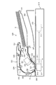
以下、本発明の実施の形態に係る画像読取装置を備えた画像形成装置について、図面を参照しながら説明する。図1は、本実施の形態に係る画像形成装置を模式的に示す断面図である。なお、以下では、ユーザーが画像形成装置に対して各種入力/設定を行う不図示の操作部に臨む位置を画像形成装置の手前側といい、背面側を奥側という。つまり、図1は、画像形成装置を手前側から見たときの画像形成装置の内部構成を示したものである。   Hereinafter, an image forming apparatus provided with an image reading apparatus according to an embodiment of the present invention will be described with reference to the drawings. FIG. 1 is a cross-sectional view schematically showing an image forming apparatus according to the present embodiment. In the following description, the position where the user faces an operation unit (not shown) where various inputs / settings are performed on the image forming apparatus is referred to as the front side of the image forming apparatus, and the back side is referred to as the back side. That is, FIG. 1 shows an internal configuration of the image forming apparatus when the image forming apparatus is viewed from the front side.

図1に示すように、画像形成装置100は、原稿積載トレイ221に積載された原稿Gの画像を読み取る画像読取装置200と、画像読取装置200で読み取られた原稿画像をシートSに形成可能な画像形成部20を有する画像形成装置本体10とを備えている。また、画像形成装置100は、画像形成部20の画像形成動作、画像読取装置200の画像読取動作等を制御する制御部50を備える。   As shown in FIG. 1, the image forming apparatus 100 can form an image reading apparatus 200 that reads an image of a document G stacked on a document stacking tray 221 and a document image read by the image reading apparatus 200 on a sheet S. And an image forming apparatus main body 10 having an image forming unit 20. The image forming apparatus 100 also includes a control unit 50 that controls the image forming operation of the image forming unit 20, the image reading operation of the image reading device 200, and the like.

画像読取装置200は、画像読取部等を有し、シートである原稿Gの画像を読み取る画像読取装置本体(以下、スキャナ部という)210と、スキャナ部210に原稿Gを自動搬送可能な自動原稿搬送装置(シート搬送部)であるADF220とを備えている。   The image reading apparatus 200 includes an image reading unit and the like, an image reading apparatus main body (hereinafter referred to as a scanner unit) 210 that reads an image of a document G that is a sheet, and an automatic document that can automatically convey the document G to the scanner unit 210. ADF220 which is a conveyance apparatus (sheet conveyance part) is provided.

画像形成装置本体10は、画像形成部20と、画像形成部20にシートSを給送するシート給送部30とを有している。さらに画像形成装置本体10は、画像が形成されたシートSを画像形成装置本体10外方(機外)に排出する排出ローラ対40aを備えた排出部40と、排出されたシートSが積載されるシート排出トレイ45とを有している。   The image forming apparatus main body 10 includes an image forming unit 20 and a sheet feeding unit 30 that feeds the sheet S to the image forming unit 20. Further, the image forming apparatus main body 10 is loaded with a discharge unit 40 having a discharge roller pair 40a for discharging the sheet S on which an image is formed to the outside (outside of the apparatus) of the image forming apparatus main body 10, and the discharged sheet S. And a sheet discharge tray 45.

画像形成部20は、トナー像が形成される感光体ドラム22と、感光体ドラム22にレーザ光を照射するレーザスキャナユニット21と、トナー像をシートSに転写する転写部24と、トナー像を定着させる定着部25とを有している。また、転写部24のシート搬送方向上流には、レジストレーションローラ対11が配設されている。なお、画像形成部20は、画像読取装置200によって原稿Gから読み取られた画像情報に基づいてシートSに画像を形成する画像形成手段を構成している。シート給送部30は、シートSが積載される給紙カセット31と、給紙カセット31内のシートSを給送する給送ローラ32と、シートSを1枚ずつに分離しながら搬送する搬送ローラ33a及び分離ローラ33bとを有している。   The image forming unit 20 includes a photosensitive drum 22 on which a toner image is formed, a laser scanner unit 21 that irradiates the photosensitive drum 22 with laser light, a transfer unit 24 that transfers the toner image to the sheet S, and a toner image. And a fixing unit 25 for fixing. Further, a registration roller pair 11 is disposed upstream of the transfer unit 24 in the sheet conveyance direction. The image forming unit 20 constitutes an image forming unit that forms an image on the sheet S based on image information read from the original G by the image reading device 200. The sheet feeding unit 30 conveys a sheet feeding cassette 31 on which the sheets S are stacked, a feeding roller 32 that feeds the sheets S in the sheet feeding cassette 31, and conveys the sheets S while separating them one by one. It has a roller 33a and a separation roller 33b.

次に、このような構成の画像形成装置100の画像形成動作について説明する。制御部50から画像読取装置200に画像読取信号が出力されると、ADF220により原稿Gが搬送され、原稿は後述する第1スキャナユニット211及び第2スキャナユニット251により読み取られる。そして、制御部50は、読み取った原稿画像を電気信号に変換し、電気信号に基づいて画像データ(画像読取情報)を作成する。   Next, an image forming operation of the image forming apparatus 100 having such a configuration will be described. When an image reading signal is output from the control unit 50 to the image reading apparatus 200, the document G is conveyed by the ADF 220, and the document is read by a first scanner unit 211 and a second scanner unit 251 described later. Then, the control unit 50 converts the read document image into an electrical signal, and creates image data (image reading information) based on the electrical signal.

この後、レーザスキャナユニット21から、この画像データに応じたレーザ光が感光体ドラム22に照射される。このとき、感光体ドラム22の表面は、不図示の帯電部材を介して予め帯電されており、レーザ光が照射されることで静電潜像が形成され、続いて静電潜像を現像器23によって現像することにより、感光体ドラム22上にトナー像が形成される。   Thereafter, a laser beam corresponding to the image data is emitted from the laser scanner unit 21 to the photosensitive drum 22. At this time, the surface of the photosensitive drum 22 is charged in advance via a charging member (not shown), and an electrostatic latent image is formed by irradiation with a laser beam. The toner image is formed on the photosensitive drum 22 by developing with the toner image 23.

一方、感光体ドラム22へのトナー像の形成動作に並行して、制御部50から給紙信号がシート給送部30に出力され、これにより給紙カセット31に収納されたシートSが給送ローラ32により給送される。給送ローラ32により給送されたシートSは、搬送ローラ33aと分離ローラ33b間の分離ニップ部で挟持されて1枚ずつに分離されて搬送される。   On the other hand, in parallel with the toner image forming operation on the photosensitive drum 22, a sheet feeding signal is output from the control unit 50 to the sheet feeding unit 30, whereby the sheet S stored in the sheet feeding cassette 31 is fed. Feeded by the roller 32. The sheets S fed by the feeding roller 32 are nipped by a separation nip portion between the conveyance roller 33a and the separation roller 33b, and are separated and conveyed one by one.

そして、分離されたシートSは、レジストレーションローラ対11により斜行が補正された後、感光体ドラム22上のトナー像と同期がとられて転写部24に送られ、転写部24に送られたシートSは、転写部24で感光体ドラム22上のトナー像が転写される。トナー像が転写されたシートSは定着部25で加熱及び加圧され、トナー像が溶融されてシートSに定着される。トナー像が定着されたシートSは、排出ローラ対40aによりシート排出トレイ45に排出され、順次、積載されていく。なお、シートSの両面に画像を形成する場合には、シートSの第1面に画像が定着された後、シートSは反転搬送路12を経てレジストレーションローラ対11に再搬送される。この後、既述した動作を繰り返すことにより、シートSの第2面に画像が形成される。   The separated sheet S is corrected for skew by the registration roller pair 11, and then sent to the transfer unit 24 in synchronization with the toner image on the photosensitive drum 22, and then to the transfer unit 24. The toner image on the photosensitive drum 22 is transferred to the sheet S by the transfer unit 24. The sheet S to which the toner image has been transferred is heated and pressed by the fixing unit 25, and the toner image is melted and fixed to the sheet S. The sheet S on which the toner image is fixed is discharged to the sheet discharge tray 45 by the discharge roller pair 40a and is sequentially stacked. When images are formed on both surfaces of the sheet S, after the image is fixed on the first surface of the sheet S, the sheet S is re-conveyed to the registration roller pair 11 via the reverse conveyance path 12. Thereafter, an image is formed on the second surface of the sheet S by repeating the above-described operation.

ここで、図2に示すように、スキャナ部210は、原稿Gの第1面(表面)の画像を読み取る第1スキャナユニット211を有している。さらに、スキャナ部210の上面には、第1流し読みガラス212と、第1流し読みガラス212と副走査方向(図2における左右方向)に並んで配置された透明部材である原稿台ガラス213が設けられている。なお、後述するようにADF220には、第2スキャナユニット251が設けられている。   Here, as illustrated in FIG. 2, the scanner unit 210 includes a first scanner unit 211 that reads an image on the first surface (front surface) of the document G. Further, on the upper surface of the scanner unit 210, there are a first flow reading glass 212, and a first plate reading glass 212 and an original platen glass 213 which is a transparent member arranged side by side in the sub-scanning direction (left and right direction in FIG. 2). Is provided. As will be described later, the ADF 220 is provided with a second scanner unit 251.

本実施の形態において、画像読取装置200は、ユーザーによって選択された、流し読みモード(ADF原稿読取モード)と、固定読みモード(原稿台ガラス原稿読取モード)とのいずれかのモードによって原稿を読み取るようになっている。流し読みモードは、ADF220により原稿を、第1スキャナユニット211の上方及び第2スキャナユニット251の下方を通過させて原稿画像を読み取るモードである。固定読みモードは、ユーザにより原稿台ガラス213に載置された原稿画像を、第1スキャナユニット211を副走査方向に移動させながら読み取るモードである。   In the present embodiment, the image reading apparatus 200 reads an original in one of a flow reading mode (ADF original reading mode) and a fixed reading mode (original table glass original reading mode) selected by the user. It is like that. The flow reading mode is a mode in which a document image is read by the ADF 220 through the first scanner unit 211 and the second scanner unit 251. The fixed reading mode is a mode for reading a document image placed on the document table glass 213 by the user while moving the first scanner unit 211 in the sub-scanning direction.

なお、ADF220は、原稿台ガラス213が手前側から開閉可能となるように、奥側に配設された後述する図4に示すヒンジ部270によりスキャナ部210に対して上下方向に開閉(回動)可能に支持されている。そして、固定読みモードの場合は、ADF220を上方回動することにより、原稿台ガラス213の上方を開放して原稿台ガラス213上に原稿を載置する。   The ADF 220 is opened and closed (rotated) in the vertical direction with respect to the scanner unit 210 by a hinge unit 270 shown in FIG. 4 (described later) disposed on the back side so that the document table glass 213 can be opened and closed from the front side. ) Supported as possible. In the fixed reading mode, the ADF 220 is rotated upward to open the upper side of the document table glass 213 and place the document on the document table glass 213.

ここで、画像読取手段である第1スキャナユニット211には、等倍光学系の密着型イメージセンサであるCIS(Contact Image Sensor)が用いられている。なお、CISは、光源としてLEDアレイから原稿Gの画像情報面に光を照射し、画像情報面で反射した反射光をセンサ素子に結像して画像情報を読み取るものである。   Here, a CIS (Contact Image Sensor), which is a contact image sensor of an equal magnification optical system, is used for the first scanner unit 211 that is an image reading unit. In the CIS, light is emitted from an LED array as a light source to an image information surface of a document G, and reflected light reflected by the image information surface is imaged on a sensor element to read image information.

また、この第1スキャナユニット211は、不図示の駆動ベルトに接続されている。ここで、流し読みモードの場合は、駆動ベルトをスキャナ部210に設けられた不図示のモータにより駆動し、第1スキャナユニット211を第1流し読みガラス212の下方の第1読取位置Aに移動させる。そして、このように第1スキャナユニット211を第1読取位置Aに停止させた状態で、ADF220によって原稿Gを第1流し読みガラス212上で移動させることにより、原稿画像を読み取る。   The first scanner unit 211 is connected to a drive belt (not shown). Here, in the case of the flow-reading mode, the driving belt is driven by a motor (not shown) provided in the scanner unit 210 and the first scanner unit 211 is moved to the first reading position A below the first flow-reading glass 212. Let Then, with the first scanner unit 211 stopped at the first reading position A in this way, the original G is moved on the first flow reading glass 212 by the ADF 220 to read the original image.

また、固定読みモードの場合は、第1スキャナユニット211を待機位置Bに移動させる。そして、このように第1スキャナユニット211を待機位置Bに移動させた後、第1スキャナユニット211を待機位置Bと終端位置Cの間で往復移動させることにより、原稿台ガラス213に載置された原稿画像を読み取る。なお、制御部50は、第1スキャナユニット211の位置を、不図示のポジションセンサとモータの回転パルス数とにより把握する。   In the fixed reading mode, the first scanner unit 211 is moved to the standby position B. Then, after the first scanner unit 211 is moved to the standby position B in this way, the first scanner unit 211 is reciprocated between the standby position B and the terminal position C to be placed on the document table glass 213. Scan the original image. The control unit 50 grasps the position of the first scanner unit 211 from a position sensor (not shown) and the number of rotation pulses of the motor.

ADF220は、原稿Gの第2面(裏面)の画像を読み取る第2スキャナユニット251を有している。ここで、第2スキャナユニット251には、第1スキャナユニット211と同様にCISが用いられている。なお、第2スキャナユニット251は、原稿搬送路Hにおける、第1スキャナユニット211の第1読取位置Aよりも原稿搬送方向下流に設けられた第2読取位置にて、原稿搬送路Hを搬送される原稿Gの第2面の画像を読み取る第2画像読取手段を構成する。なお、第2読取位置は、第2流し読みガラス252に対向する位置である。   The ADF 220 includes a second scanner unit 251 that reads an image on the second surface (back surface) of the document G. Here, the CIS is used for the second scanner unit 251 similarly to the first scanner unit 211. The second scanner unit 251 is transported on the document transport path H at a second reading position provided in the document transport path H downstream of the first reading position A of the first scanner unit 211 in the document transport direction. A second image reading means for reading an image on the second surface of the original G to be printed. The second reading position is a position facing the second flow reading glass 252.

また、ADF220は、図2及び図3に示すように、流し読みのための原稿Gが積載される原稿積載トレイ221と、流し読みをする際に、原稿搬送路Hを介して原稿Gを搬送する原稿搬送部222とを有している。また、ADF220は、流し読みされた原稿Gが排出されて積載される原稿排出部223を有している。なお、ADF220は、固定読みをする際に原稿台ガラス213に載置された原稿Gが移動しないように、不図示の樹脂製プレートによって原稿Gを押圧可能に構成されている。   As shown in FIGS. 2 and 3, the ADF 220 conveys the document G through the document stacking path 221 on which the document G for flow reading is stacked and the document conveyance path H when performing the flow reading. And a document conveying section 222. The ADF 220 has a document discharge unit 223 on which the flow-read original G is discharged and stacked. The ADF 220 is configured such that the original G can be pressed by a resin plate (not shown) so that the original G placed on the original table glass 213 does not move during fixed reading.

原稿搬送部222は、図2に示すように、原稿積載トレイ221に積載された原稿Gを給送する原稿給送ローラ231と、原稿Gを1枚ずつに分離する分離ローラ対232と、分離された原稿Gを引き抜く第1搬送ローラ対233とを有している。さらに、原稿搬送部222は、原稿Gを搬送する第2搬送ローラ対234と、第3搬送ローラ対236と、第4搬送ローラ対238と、第5搬送ローラ対240とを有している。   As shown in FIG. 2, the document conveying unit 222 includes a document feeding roller 231 that feeds the document G stacked on the document stacking tray 221, a separation roller pair 232 that separates the document G one by one, and a separation roller 231. A first conveying roller pair 233 for pulling out the original G. Further, the document conveyance unit 222 includes a second conveyance roller pair 234 that conveys the document G, a third conveyance roller pair 236, a fourth conveyance roller pair 238, and a fifth conveyance roller pair 240.

また、原稿搬送部222は、第2搬送ローラ対234と第3搬送ローラ対236との間に配設されて原稿Gの斜行を矯正(補正)するレジストレーションローラ対235と、第1プラテンローラ237と、排出ローラ対241とを有している。また、原稿搬送部222は、第2流し読みガラス252と対向するように配設され、原稿Gを搬送する第2プラテンローラ239を有している。   The document conveying unit 222 is disposed between the second conveying roller pair 234 and the third conveying roller pair 236 and corrects (corrects) the skew of the original G. The first platen It has a roller 237 and a discharge roller pair 241. In addition, the document conveying section 222 is disposed so as to face the second flow reading glass 252 and has a second platen roller 239 that conveys the document G.

第1プラテンローラ237は、原稿Gを第2面側から押さえて、原稿Gの第1流し読みガラス212からの浮き上がりを抑制するためのものである。そして、この第1プラテンローラ237は、第3搬送ローラ対236と第4搬送ローラ対238との間に位置する第1流し読みガラス212の直上、即ち第1読取位置Aに位置する第1スキャナユニット211と対向するように配設されている。なお、この第1プラテンローラ237は、不図示のモータにより回転駆動される。   The first platen roller 237 is for holding the document G from the second surface side and suppressing the document G from being lifted from the first flow reading glass 212. The first platen roller 237 is a first scanner positioned at the first reading position A, that is, directly above the first flow reading glass 212 positioned between the third conveying roller pair 236 and the fourth conveying roller pair 238. The unit 211 is disposed so as to face the unit 211. The first platen roller 237 is rotationally driven by a motor (not shown).

また、排出ローラ対241は、第5搬送ローラ対240の下流に配設され、画像読取を終えた原稿Gを原稿排出部223に排出するためのものである。第2プラテンローラ239は、第2流し読みガラス252と対向するように配設され、原稿Gを第1面側から押さえて第2流し読みガラス252との間隔を一定に保ちながら搬送するためのものである。   Further, the discharge roller pair 241 is disposed downstream of the fifth transport roller pair 240, and discharges the original G after image reading to the original discharge unit 223. The second platen roller 239 is disposed so as to face the second flow reading glass 252 and is used for conveying the document G while holding the original G from the first surface side and keeping the distance from the second flow reading glass 252 constant. Is.

次に、このような構成の画像読取装置200による画像読取動作について説明する。まず、原稿積載トレイ221上に載置された原稿Gは、原稿給送ローラ231により給送され、分離ローラ対232の分離ニップ部で1枚ずつに分離される。分離された原稿Gは、第1搬送ローラ対233により引き抜かれた後、第2搬送ローラ対234により、レジストレーションローラ対235のニップ部まで搬送される。   Next, an image reading operation by the image reading apparatus 200 having such a configuration will be described. First, the document G placed on the document stacking tray 221 is fed by the document feeding roller 231 and separated one by one at the separation nip portion of the separation roller pair 232. The separated document G is pulled out by the first transport roller pair 233 and then transported to the nip portion of the registration roller pair 235 by the second transport roller pair 234.

ここで、原稿Gがレジストレーションローラ対235のニップ部に到達した時点では、レジストレーションローラ対235は静止状態となっており、これにより原稿Gは、先端をニップ部に当接させた状態で停止する。この状態で、原稿搬送方向上流側の第2搬送ローラ対234によって原稿Gの後端を所定量押し込むことにより、原稿Gを撓ませて湾曲を生じさせる。   Here, when the document G reaches the nip portion of the registration roller pair 235, the registration roller pair 235 is in a stationary state, whereby the document G is in a state where the leading end is in contact with the nip portion. Stop. In this state, the document G is bent and curved by pushing the rear end of the document G by a predetermined amount by the second conveyance roller pair 234 on the upstream side in the document conveyance direction.

ここで、原稿Gが斜行している場合、主走査方向(原稿搬送方向に直交する幅方向)に対して原稿Gの先端は傾いているが、既述の湾曲による原稿Gのコシ(剛性)で、原稿先端が、主走査方向に平行なレジストレーションローラ対235のニップ線に倣う。これにより、原稿先端の傾きが解消され、原稿Gの斜行が補正される。   Here, when the document G is skewed, the leading edge of the document G is inclined with respect to the main scanning direction (the width direction orthogonal to the document conveyance direction), but the stiffness (rigidity) of the document G due to the above-described curvature. ), The leading edge of the document follows the nip line of the registration roller pair 235 parallel to the main scanning direction. As a result, the inclination of the leading edge of the document is eliminated, and the skew of the document G is corrected.

斜行補正の後、レジストレーションローラ対235による原稿Gの搬送が開始され、原稿Gは、第3搬送ローラ対236によって更に下流へと搬送され、第1流し読みガラス212上の画像読取位置に到達する。そして、第1スキャナユニット211によって原稿Gの第1面の画像読取が所定の速度で行われる。この後、原稿Gは、第4搬送ローラ対238により搬送される。ここで、ユーザーにより原稿Gの第2面も読み取る指示がされていれば、制御部50の制御で、既述の第1面読み取りの後、第2流し読みガラス252上の画像読取位置にて、第2スキャナユニット251により原稿Gの第2面の画像読取が所定の速度で行われる。   After the skew correction, the conveyance of the original G by the registration roller pair 235 is started, and the original G is further conveyed downstream by the third conveyance roller pair 236 to reach the image reading position on the first flow reading glass 212. To reach. Then, the first scanner unit 211 reads an image on the first side of the document G at a predetermined speed. Thereafter, the original G is conveyed by the fourth conveying roller pair 238. Here, if the user instructs to read the second side of the document G, the controller 50 controls the image reading position on the second flow reading glass 252 after the first side reading described above. Then, the second scanner unit 251 reads the image on the second side of the document G at a predetermined speed.

さらに、画像読取後の原稿Gが、第5搬送ローラ対240と排出ローラ対241とにより原稿排出部223に排出される。そして、原稿積載トレイ221上に載置された原稿Gがなくなるまで、既述した動作を繰り返す。原稿積載トレイ221上に載置された原稿Gの有無は、不図示のセンサによって検知可能になっている。   Further, the original G after image reading is discharged to the original discharge unit 223 by the fifth conveying roller pair 240 and the discharge roller pair 241. Then, the above-described operation is repeated until there are no more documents G placed on the document stacking tray 221. The presence / absence of the document G placed on the document stacking tray 221 can be detected by a sensor (not shown).

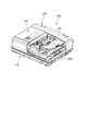
ところで、図4及び図5に示すように、ADF220の底面には、前側突き当て部263と奥側突き当て部264が設けられている。この前側突き当て部263と奥側突き当て部264は、図5に示す第1流し読みガラス212上の前側突き当て領域212a、奥側突き当て領域212bにそれぞれ当接するように配設されている。そして、突き当て部263,264を第1流し読みガラス212上の突き当て領域212a,212bに当接させることにより、第1流し読みガラス212と第1プラテンローラ237との間に原稿搬送路Hの一部を成す所定の間隙が形成される。   Incidentally, as shown in FIGS. 4 and 5, a front abutting portion 263 and a back abutting portion 264 are provided on the bottom surface of the ADF 220. The front side abutting part 263 and the back side abutting part 264 are disposed so as to abut on the front side abutting area 212a and the back side abutting area 212b on the first flow reading glass 212 shown in FIG. . Then, the abutting portions 263 and 264 are brought into contact with the abutting areas 212a and 212b on the first flow reading glass 212, whereby the document transport path H is provided between the first flow reading glass 212 and the first platen roller 237. A predetermined gap that forms a part of is formed.

ここで、所定の間隙が形成されず、間隔が広がると、搬送される原稿Gが第1流し読みガラス212に対して上方に浮き上がってしまい、読取画像がぼやけてしまう。また、突き当て部263,264が前側突き当て領域212a、奥側突き当て領域212bのどちらか一方でしか当接がなされていない、いわゆる片当たりの場合、間隙が図4の左右方向である主走査方向において不均一となる。この場合には、搬送される原稿Gに対して主走査方向に搬送抵抗差が生じ、この結果、原稿Gの斜行等が発生し、読取画像の幾何特性に悪影響を及ぼす。   Here, when the predetermined gap is not formed and the interval is widened, the conveyed original G floats upward with respect to the first flow reading glass 212, and the read image becomes blurred. When the abutting portions 263 and 264 are in contact with only one of the front-side abutting region 212a and the rear-side abutting region 212b, so-called one-side contact, the gap is in the horizontal direction in FIG. It becomes non-uniform in the scanning direction. In this case, a conveyance resistance difference occurs in the main scanning direction with respect to the conveyed document G, and as a result, skew of the document G occurs, which adversely affects the geometric characteristics of the read image.

そこで、このような画像不良を回避するためには、前側突き当て部263と奥側突き当て部264の両方を第1流し読みガラス212上に確実に当接させると共に、当接状態を保持する必要がある。このため、本実施の形態では、ADF220の底面前側に係合部材の一例である磁石261を設け、スキャナ部210上面前側に被係合部材の一例である鉄板等の磁性部材である着磁板262を設けている。   Therefore, in order to avoid such an image defect, both the front side abutting part 263 and the back side abutting part 264 are surely brought into contact with the first flow reading glass 212 and the contact state is maintained. There is a need. Therefore, in the present embodiment, a magnet 261 which is an example of an engaging member is provided on the front side of the bottom surface of the ADF 220, and a magnetized plate which is a magnetic member such as an iron plate which is an example of a member to be engaged on the front side of the upper surface of the scanner unit 210. 262 is provided.

ここで、磁石261はADF220の回動端の底面に設けられ、着磁板262は、ADF220を閉じたときの磁石261の位置に対応する位置に配設されている。このため、ADF220を閉じると、磁石261と着磁板262が磁性的に係合し、安定したADF220の保持が可能となる。つまり、本実施の形態において、図4に示すように、磁石261と着磁板262は、ADF220を閉鎖位置に保持する保持手段260を構成する。そして、閉鎖位置において、ADF220は原稿台ガラス213を覆い、原稿台ガラス213に載置された原稿を押さえる。   Here, the magnet 261 is provided on the bottom surface of the rotation end of the ADF 220, and the magnetized plate 262 is disposed at a position corresponding to the position of the magnet 261 when the ADF 220 is closed. For this reason, when the ADF 220 is closed, the magnet 261 and the magnetized plate 262 are magnetically engaged, and the ADF 220 can be stably held. That is, in the present embodiment, as shown in FIG. 4, the magnet 261 and the magnetized plate 262 constitute a holding means 260 that holds the ADF 220 in the closed position. In the closed position, the ADF 220 covers the document table glass 213 and presses the document placed on the document table glass 213.

ここで、着磁板262は、図6の(a)に示すように、図6の左右方向(原稿搬送方向)である副走査方向において、第1流し読みガラス212と重なる位置、言い換えれば第1スキャナユニット211の副走査方向の位置に対応した位置に配置されている。これにより、閉じられた際、ADF220は副走査方向において第1流し読みガラス212を中心として保持されるようになり、既述した、前側突き当て部263及び奥側突き当て部264の第1流し読みガラス212上への当接が強固で安定したものとなる。   Here, as shown in FIG. 6A, the magnetized plate 262 overlaps with the first flow reading glass 212 in the sub-scanning direction which is the left-right direction (original transport direction) in FIG. The one scanner unit 211 is arranged at a position corresponding to the position in the sub-scanning direction. As a result, when closed, the ADF 220 is held around the first flow reading glass 212 in the sub-scanning direction, and the first flow of the front-side butting portion 263 and the back-side butting portion 264 described above. The contact on the reading glass 212 is strong and stable.

なお、磁石261及び着磁板262が、図6の(b)に示すように、副走査方向において、第1流し読みガラス212と離れた位置に配置された場合には、第1流し読みガラス212付近は磁性的係合による保持力の影響が小さくなる。この場合、ADF220の底面のたわみ、反りにより、前側突き当て部263及び奥側突き当て部264が第1流し読みガラス212から浮き上がり、既述の画像不良を発生させる恐れがある。   Note that when the magnet 261 and the magnetized plate 262 are arranged at a position away from the first flow reading glass 212 in the sub-scanning direction as shown in FIG. 6B, the first flow reading glass. In the vicinity of 212, the influence of the holding force due to magnetic engagement becomes small. In this case, due to the deflection and warping of the bottom surface of the ADF 220, the front side abutting part 263 and the back side abutting part 264 may be lifted from the first flow reading glass 212, and the above-described image defects may occur.

このように、図6の(b)に示すような磁石261及び着磁板262の配置は好ましくない。したがって、図6の(a)に示すように、磁石261及び着磁板262の主走査方向投影領域E内に、前側突き当て領域212a及び奥側突き当て領域212bの少なくとも一部が含まれるような配置が好ましい。   Thus, the arrangement of the magnet 261 and the magnetized plate 262 as shown in FIG. 6B is not preferable. Therefore, as shown in FIG. 6A, at least a part of the front-side butting area 212a and the back-side butting area 212b is included in the main scanning direction projection area E of the magnet 261 and the magnetized plate 262. Is preferable.

本実施の形態においては、図5に示すように、ADF220には、磁石261及び着磁板262によるADF220の保持を解除するための把手部である保持解除レバー281が設けられている。この保持解除レバー281は、後述する図10に示す、ADF220の保持を解除する保持解除手段280の一部を成し、ユーザーは保持解除レバー281を下方から押し上げることで、ADF220の保持解除を行う。ここで、保持解除レバー281はADF220の回動端側の副走査方向における中央部に配設されており、このような位置に保持解除レバー281を配設することにより、ユーザーによる操作を容易なものとしている。   In the present embodiment, as shown in FIG. 5, the ADF 220 is provided with a holding release lever 281 that is a handle for releasing the holding of the ADF 220 by the magnet 261 and the magnetized plate 262. The holding release lever 281 forms a part of holding release means 280 for releasing the holding of the ADF 220 shown in FIG. 10 described later, and the user releases the holding of the ADF 220 by pushing up the holding releasing lever 281 from below. . Here, the holding release lever 281 is disposed at the center portion in the sub-scanning direction on the rotation end side of the ADF 220, and by disposing the holding release lever 281 at such a position, the user can easily operate. It is supposed to be.

ところで、既述したように固定読みモードの場合は、ADF220を上方回動させ、ADF220を、原稿台ガラス213を開放して原稿を載置することが可能な第1の位置である開放位置に移動させた状態で、原稿台ガラス213上に原稿を載置する。なお、スキャナ部210の一端部である奥側端部には、ADF220を回動可能とするため、図4に示すヒンジ部70が設けられており、このヒンジ部270により、ADF220はスキャナ部210に対して回動可能(移動可能)に支持される。   By the way, in the case of the fixed reading mode as described above, the ADF 220 is rotated upward, and the ADF 220 is moved to the open position that is the first position where the original table glass 213 can be opened and the original can be placed. The original is placed on the platen glass 213 in the moved state. Note that a hinge part 70 shown in FIG. 4 is provided at the back end, which is one end part of the scanner part 210, so that the ADF 220 can be rotated. The hinge part 270 causes the ADF 220 to be connected to the scanner part 210. Is supported so as to be rotatable (movable).

ここで、図7に示すように、ヒンジ部270は、ヒンジ回動軸271を有し、ADF220はスキャナ部210に対して、ヒンジ回動軸271を中心として回動する。また、ヒンジ部270は、その内部にヒンジバネA272及びヒンジバネB273を有し、このヒンジバネA272及びヒンジバネB273により、ADF220を上方に回動させる方向に付与するヒンジトルクを発生させる。ここで、ヒンジバネA272及びヒンジバネB273のバネ力や、その組み合わせにより、ユーザーがADF220を開放する際の操作性に影響を及ぼすヒンジトルクの調整が可能である。   Here, as shown in FIG. 7, the hinge portion 270 has a hinge rotation shaft 271, and the ADF 220 rotates about the hinge rotation shaft 271 with respect to the scanner portion 210. The hinge portion 270 includes a hinge spring A272 and a hinge spring B273 inside thereof, and the hinge spring A272 and the hinge spring B273 generate a hinge torque that is applied in a direction in which the ADF 220 is rotated upward. Here, the hinge torque that affects the operability when the user opens the ADF 220 can be adjusted by the spring force of the hinge spring A272 and the hinge spring B273 and the combination thereof.

次に、ADF220開閉時のヒンジ回動軸271周りのトルク線図である図8を用いてヒンジトルクの調整例について説明する。図8の(a)は、ヒンジ調整例1である。このヒンジ調整例1では、既述した図4に示すADF220の開閉角θが20°未満の範囲においては、ADF220の自重により閉鎖方向に働く自重トルクの方が、ヒンジトルクより大きくなるように調整されている。このため、ADF220の開閉角θが20°未満の場合にはADF220は自重で閉じる。   Next, an example of adjusting the hinge torque will be described with reference to FIG. 8 which is a torque diagram around the hinge rotation shaft 271 when the ADF 220 is opened and closed. (A) of FIG. 8 is the hinge adjustment example 1. FIG. In this hinge adjustment example 1, in the range where the opening / closing angle θ of the ADF 220 shown in FIG. 4 is less than 20 °, adjustment is performed so that the own weight torque acting in the closing direction due to the own weight of the ADF 220 is larger than the hinge torque. Has been. For this reason, when the opening / closing angle θ of the ADF 220 is less than 20 °, the ADF 220 is closed by its own weight.

また、ヒンジ調整例1では、開閉角θが20°以上の範囲において、ADF220の自重トルクと、開閉角θが20°以上となった際に発生するヒンジ部270内部の摩擦による負荷トルク(不図示)との総和が、ヒンジトルクと釣り合うように調整されている。このため、ADF220はその開閉角θを維持して静止することが可能であり、その際に外力による支えは不要である。従って、ヒンジ調整例1の場合、ユーザーは、固定読みのために原稿台ガラス213上に原稿Gを載置する際に、開閉角θが20°以上でADF220を開放した場合、ADF220から手を放して原稿Gを載置することが可能である。   Further, in the hinge adjustment example 1, in the range where the opening / closing angle θ is 20 ° or more, the self-weight torque of the ADF 220 and the load torque due to the friction in the hinge portion 270 generated when the opening / closing angle θ becomes 20 ° or more (indefinite) And the sum total with the figure are adjusted so as to balance the hinge torque. For this reason, the ADF 220 can be kept stationary while maintaining its opening / closing angle θ, and at that time, support by an external force is unnecessary. Therefore, in the case of hinge adjustment example 1, when placing the document G on the platen glass 213 for fixed reading, if the user opens the ADF 220 with an opening / closing angle θ of 20 ° or more, the user moves his / her hand from the ADF 220. It is possible to place the original G by releasing it.

図8の(b)は、ヒンジ調整例2である。このヒンジ調整例2では、ADF220の開閉角θが20°未満の範囲においては、ADF220の自重により閉鎖方向に働く自重トルクの方が、ヒンジトルクより小さくなるように調整されている。このため、ADF220を開くと、開閉角θが20°未満の場合でもADF220は自動的に上方へ回動する。また、ヒンジ調整例2では、開閉角θが20°以上の範囲においては、ADF220の自重トルクと、開閉角θが20°以上となった際に発生するヒンジ部270内部の摩擦による負荷トルク(不図示)との総和が、ヒンジトルクと釣り合うように調整されている。このため、ヒンジ調整例2においては、開閉角θが20°以上の範囲においてADF220はその開閉角θを維持して静止することが可能であり、その際に外力による支えは不要である。   FIG. 8B is a hinge adjustment example 2. In this hinge adjustment example 2, when the opening / closing angle θ of the ADF 220 is less than 20 °, the self-weight torque that works in the closing direction due to the self-weight of the ADF 220 is adjusted to be smaller than the hinge torque. For this reason, when the ADF 220 is opened, the ADF 220 automatically rotates upward even when the opening / closing angle θ is less than 20 °. Further, in the hinge adjustment example 2, in the range where the opening / closing angle θ is 20 ° or more, the self-weight torque of the ADF 220 and the load torque due to the friction inside the hinge portion 270 generated when the opening / closing angle θ becomes 20 ° or more ( (Not shown) is adjusted to balance the hinge torque. For this reason, in the hinge adjustment example 2, the ADF 220 can remain stationary while maintaining the opening / closing angle θ in a range where the opening / closing angle θ is 20 ° or more, and support by an external force is not necessary at that time.

なお、本実施の形態において、固定読みによる画像読取時には、原稿台ガラス213を露出させるためADF220の保持を解除した際、ヒンジ部270によりADF220を上方回動させるようにしている。このため、本実施の形態では、ヒンジ調整例2によりヒンジトルクを調整している。   In this embodiment, at the time of image reading by fixed reading, the ADF 220 is rotated upward by the hinge portion 270 when the holding of the ADF 220 is released to expose the original table glass 213. For this reason, in the present embodiment, the hinge torque is adjusted by the hinge adjustment example 2.

ここで、このようにヒンジトルクを調整した場合、ADF220は自重で閉じないため、原稿台ガラス213に原稿を載置した後、ユーザーがADF220に対して閉鎖方向に力を加えてADF220を閉じる。なお、このようにADF220を閉じると、磁石261と着磁板262とが係合され、これによりADF220は原稿を押さえるための第2の位置である閉鎖位置に保持される。   Here, when the hinge torque is adjusted in this way, the ADF 220 does not close due to its own weight. Therefore, after placing the document on the platen glass 213, the user applies a force to the ADF 220 in the closing direction to close the ADF 220. When the ADF 220 is closed in this manner, the magnet 261 and the magnetized plate 262 are engaged with each other, whereby the ADF 220 is held in the closed position that is the second position for pressing the document.

また、ADF220を開放する際には、既述した保持解除レバー281を押し上げる操作を行うことによって磁石261と着磁板262の係合を解除することにより、ADF220の保持を解除する。なお、このようにADF220の保持を解除した場合、ヒンジトルクによりADF220は開閉角20°の位置まで開くようになる。つまり、本実施の形態においては、ヒンジトルクにより、保持解除レバー281を押し上げる操作だけでADF220を開閉角20°の位置まで開くことができる。このため、ユーザーは、ADF220の重量を負担することなくADF220を開放することができ、操作性が向上する。   Further, when the ADF 220 is opened, the holding of the ADF 220 is released by releasing the engagement between the magnet 261 and the magnetized plate 262 by pushing up the holding release lever 281 described above. When the holding of the ADF 220 is released in this way, the ADF 220 opens to a position with an opening / closing angle of 20 ° by the hinge torque. That is, in the present embodiment, the ADF 220 can be opened to the position of the opening / closing angle of 20 ° only by pushing up the holding release lever 281 by the hinge torque. For this reason, the user can open the ADF 220 without burdening the weight of the ADF 220, and the operability is improved.

次に、保持解除レバー281の操作によるADF220の保持を解除するための構成について説明する。図9は、ADF220が原稿台ガラス213を被覆するように閉鎖位置に保持されている状態を示す斜視図である。ここで、既述したように、ADF220は、保持解除レバー281と磁石261を有しており、保持解除レバー281と磁石261は連結部材である回動軸(軸状部材)282によって連結されている。そして、図10に示すように、回動軸282の両端はADF筐体220aに形成された軸支持部283に支持されている。また、このADF筐体220aには軸規制部284が形成されており、この軸規制部284に回動軸282が挿通される。   Next, a configuration for releasing the holding of the ADF 220 by operating the holding release lever 281 will be described. FIG. 9 is a perspective view showing a state in which the ADF 220 is held in the closed position so as to cover the platen glass 213. Here, as described above, the ADF 220 includes the holding release lever 281 and the magnet 261, and the holding release lever 281 and the magnet 261 are connected by the rotation shaft (shaft-like member) 282 that is a connecting member. Yes. As shown in FIG. 10, both ends of the rotation shaft 282 are supported by shaft support portions 283 formed in the ADF housing 220a. In addition, a shaft restricting portion 284 is formed in the ADF casing 220a, and the rotating shaft 282 is inserted through the shaft restricting portion 284.

ADF220の保持を解除する場合は、既述したようにユーザーは保持解除レバー281を押し上げる。ここで、保持解除レバー281を押し上げると、保持解除レバー281と一体に回動軸282が矢印E方向に回転する。さらに、回動軸282が回転すると、回動軸282と一体に磁石261が矢印E方向に回動し、このように磁石261が回動すると、磁石261は着磁板262との磁気的な係合が解除され、ADF220の保持が解除される。つまり、本実施の形態において、保持解除レバー281と、回動軸282と、軸規制部284とによりADF220の保持を解除する保持解除手段280が構成される。   When releasing the holding of the ADF 220, the user pushes up the holding release lever 281 as described above. Here, when the holding release lever 281 is pushed up, the rotation shaft 282 rotates in the direction of arrow E integrally with the holding release lever 281. Further, when the rotating shaft 282 rotates, the magnet 261 rotates in the direction of arrow E integrally with the rotating shaft 282. When the magnet 261 rotates in this way, the magnet 261 is magnetically coupled to the magnetized plate 262. The engagement is released and the holding of the ADF 220 is released. That is, in the present embodiment, the holding release lever 281, the rotation shaft 282, and the shaft restricting unit 284 constitute the holding release means 280 that releases the holding of the ADF 220.

そして、ADF220の保持が解除されると、ADF220は、既述したヒンジ調整例2によってヒンジトルクが調整されているヒンジ部270により自動的に開閉角20°の位置まで開くので、原稿台ガラス213への原稿載置が可能となる。このように、本実施の形態によれば、保持解除レバー281の押し上げ操作のみで、ADF220の保持を解除すると共にADF220を上方へ開放することができ、原稿台ガラス213への原稿載置が可能となる。   When the holding of the ADF 220 is released, the ADF 220 is automatically opened to the position of the opening / closing angle of 20 ° by the hinge portion 270 whose hinge torque has been adjusted by the hinge adjustment example 2 described above. The original can be placed on the document. Thus, according to the present embodiment, the holding of the ADF 220 can be released and the ADF 220 can be opened upward only by pushing up the holding release lever 281, and the document can be placed on the platen glass 213. It becomes.

ここで、既述したように、操作性のために、保持解除レバー281はADF220の回動端の副走査方向における中央部に配設されている。また、読取画像不良を回避するため、磁石261は副走査方向において、第1流し読みガラス212と重なる位置に配置されている。この場合、回動軸282は、ADF220の副走査方向の長さ半分程度の長さを有する。また、保持解除レバー281は回動軸282の副走査方向、言い換えれば回動軸282の軸方向における中央側の一端側に取り付けられ、磁石261は回動軸282の副走査方向における他端側に取り付けられる。さらに、回動軸282の両端は軸支持部283によって回転自在に軸支されている。   Here, as described above, for the sake of operability, the holding release lever 281 is disposed at the center of the rotation end of the ADF 220 in the sub-scanning direction. In order to avoid reading image defects, the magnet 261 is arranged at a position overlapping the first flow reading glass 212 in the sub-scanning direction. In this case, the rotation shaft 282 has a length that is approximately half the length of the ADF 220 in the sub-scanning direction. The holding release lever 281 is attached to one end side of the center side in the sub-scanning direction of the rotating shaft 282, in other words, the axial direction of the rotating shaft 282, and the magnet 261 is the other end side of the rotating shaft 282 in the sub-scanning direction. Attached to. Further, both ends of the rotation shaft 282 are rotatably supported by a shaft support portion 283.

この構成の場合、ユーザーが保持解除レバー281を押し上げ操作すると、回動軸282には上方に撓む方向にも力が作用する。ここで、本実施の形態の画像読取装置200は、A3サイズの原稿を読み取ることができるようになっており、この場合、回動軸282の長さが長くなる。このように回動軸282が長くなると、磁石261と着磁板262との係合力が大きい場合、ユーザーが保持解除レバー281を押し上げ操作すると、回動軸282が上方に撓んでしまう。なお、撓みが大きくなると、軸支持部283での回動軸282に対する摩擦抵抗が増加する。そして、摩擦抵抗が増加すると、回動軸28の回転不良が発生するので、回動軸282を回転させるためには、保持解除レバー281に大きな力を加えなければならなくなり、操作性が低下する。   In the case of this configuration, when the user pushes up the holding release lever 281, a force acts on the rotating shaft 282 in the direction of bending upward. Here, the image reading apparatus 200 according to the present embodiment is capable of reading an A3 size document. In this case, the length of the rotating shaft 282 is increased. When the rotation shaft 282 becomes longer in this way, when the engagement force between the magnet 261 and the magnetized plate 262 is large, when the user pushes up the holding release lever 281, the rotation shaft 282 is bent upward. In addition, when bending becomes large, the frictional resistance with respect to the rotating shaft 282 in the shaft support part 283 will increase. When the frictional resistance is increased, a rotation failure of the rotation shaft 28 occurs. Therefore, in order to rotate the rotation shaft 282, a large force must be applied to the holding release lever 281 and the operability is deteriorated. .

そこで、本実施の形態では、既述したようにADF筐体220aに、例えば回動軸282の径よりも大きい穴形状の軸規制部284を形成し、この軸規制部284に回動軸282を挿通させている。これにより、保持解除レバー281の押し上げ操作に伴い回動軸282が上方に大きく撓もうとすると、回動軸282が軸規制部284の内周面と接触するようになり、回動軸282の所定量以上の撓み(変形)を規制することができる。そして、このように回動軸282の所定量以上の撓みを規制することにより、軸支持部283での回動軸282に対する摩擦抵抗を低減することができ、保持解除レバー281の押し上げ操作時における回動軸282の回転不良の発生を防ぐことができる。   Therefore, in this embodiment, as described above, the ADF housing 220a is formed with the shaft restricting portion 284 having a hole shape larger than the diameter of the turning shaft 282, for example, and the turning shaft 282 is formed on the shaft restricting portion 284. Is inserted. Thus, when the rotation shaft 282 is largely bent upward as the holding release lever 281 is pushed up, the rotation shaft 282 comes into contact with the inner peripheral surface of the shaft restricting portion 284, and the rotation shaft 282 The bending (deformation) of a predetermined amount or more can be regulated. In addition, by restricting the deflection of the rotation shaft 282 by a predetermined amount or more, the frictional resistance of the shaft support portion 283 with respect to the rotation shaft 282 can be reduced, and the holding release lever 281 can be pushed up. It is possible to prevent the rotation failure of the rotation shaft 282.

このように、本実施の形態においては、保持解除レバー281の押し上げ操作時、回動軸282が上方に大きく撓もうとすると、軸規制部284により回動軸282の変形を規制するようにしている。これにより、保持解除レバー281の押し上げ操作時における回動軸28の回転不良の発生を防ぐことができ、操作性を向上させることができる。   As described above, in the present embodiment, when the holding shaft release lever 281 is pushed up, if the rotating shaft 282 is bent upward, the shaft restricting portion 284 restricts the deformation of the rotating shaft 282. Yes. Thereby, it is possible to prevent the rotation failure of the rotating shaft 28 during the push-up operation of the holding release lever 281 and improve the operability.

なお、既述したように、軸規制部284は回動軸282が挿通される穴形状である。ここで、軸規制部284を、回動軸282の径とほぼ同じ径の嵌合穴にした場合、既述したような回動軸282の変形は完全に規制される。しかし、実際には、ADF筐体220aの成形時の歪み、ヒンジトルク付勢によるADF筐体220aの変形等によって、回動軸282は真直ではなく、僅かに変形を有することが考えられる。   As described above, the shaft restricting portion 284 has a hole shape through which the rotating shaft 282 is inserted. Here, when the shaft restricting portion 284 is a fitting hole having a diameter substantially the same as the diameter of the rotating shaft 282, the deformation of the rotating shaft 282 as described above is completely restricted. However, in reality, it is conceivable that the rotation shaft 282 is not straight but slightly deformed due to distortion during molding of the ADF housing 220a, deformation of the ADF housing 220a due to biasing of the hinge torque, and the like.

これを考慮すると、軸規制部284を既述したような嵌合穴にした場合、回動軸282の僅かな変形も許容しないため、回動軸282が回転する際に軸規制部284との間で大きな摩擦抵抗を発生させる恐れがある。この場合、ユーザーによる保持解除レバー281の押し上げが困難になる恐れがある。   In consideration of this, when the shaft restricting portion 284 is a fitting hole as described above, slight deformation of the rotating shaft 282 is not allowed, and therefore, when the rotating shaft 282 rotates, There is a risk of generating large frictional resistance. In this case, it may be difficult for the user to push up the holding release lever 281.

このため、本実施の形態では、軸規制部284を、保持解除レバー281が押し上げられていない状態では、図10に示すように所定の間隙を有するよう、既述したように回動軸282の径よりも大きい穴形状に形成している。なお、この間隙は、保持解除レバー281の押し上げ方向(操作方向)となる回動軸282の上方に形成されている。また、この間隙は、回動軸282の保持解除レバー281の押し上げによる回動軸282の大きな変形の規制と、回動軸282が元々有する僅かな変形の許容とを、共に満足するように形成されている。   For this reason, in the present embodiment, as described above, the shaft restricting portion 284 has the predetermined clearance as shown in FIG. 10 when the holding release lever 281 is not pushed up. It is formed in a hole shape larger than the diameter. This gap is formed above the rotation shaft 282 that is the direction in which the holding release lever 281 is pushed up (operation direction). In addition, this gap is formed so as to satisfy both the restriction of large deformation of the rotation shaft 282 by pushing up the holding release lever 281 of the rotation shaft 282 and the slight deformation allowance inherent in the rotation shaft 282. Has been.

そして、このような間隙を軸規制部284と回動軸282との間に形成することにより、保持解除レバー281が押し上げられた際、回動軸282は上方に撓むことができる。また、大きく撓む前に軸規制部284に接触することができ、回動軸282の変形を規制することができる。なお、このように回動軸282が軸規制部284に接触した場合、軸規制部284に接触する部分は回動軸282の一部であるので、軸規制部284との間で発生する摩擦抵抗は小さく、回動軸282の回転負荷に及ぼす影響は少ない。   By forming such a gap between the shaft restricting portion 284 and the rotation shaft 282, the rotation shaft 282 can bend upward when the holding release lever 281 is pushed up. In addition, the shaft restricting portion 284 can be contacted before being largely bent, and deformation of the rotating shaft 282 can be restricted. In addition, when the rotating shaft 282 contacts the shaft restricting portion 284 in this way, the portion that contacts the shaft restricting portion 284 is a part of the rotating shaft 282, and therefore, friction generated between the shaft restricting portion 284 and the shaft restricting portion 284. The resistance is small and the influence on the rotational load of the rotating shaft 282 is small.

ここで、軸規制部284の形状は、保持解除レバー281が押し上げられていない状態のとき、すなわち保持解除レバー281が操作されていないとき、回動軸282との間に所定の間隙を有していればどのような形状でも良い。この軸規制部284の形状としては、例えば図11の(a)に示すような長丸穴、図11の(b)に示すような長方形穴がある。   Here, the shape of the shaft restricting portion 284 has a predetermined gap with the rotating shaft 282 when the holding release lever 281 is not pushed up, that is, when the holding release lever 281 is not operated. Any shape is acceptable. Examples of the shape of the shaft restricting portion 284 include an oblong hole as shown in FIG. 11A and a rectangular hole as shown in FIG.

なお、軸規制部284が図11の(a)に示す長丸穴形状の場合、保持解除レバー281が操作されていないときには、回動軸282の、回動軸282の撓む方向である上方向に所定の間隙g1が形成され、回動軸282の両側に間隙g2が形成される。ここで、この軸規制部284は、両側の間隙g2の大きさが、所定の間隙g1よりも小さくなるように形成されており、このように軸規制部284を形成することにより、保持解除レバー281を操作すると、回動軸282は確実に上方に撓むようになる。   When the shaft restricting portion 284 has an oblong hole shape shown in FIG. 11A, when the holding release lever 281 is not operated, the rotation shaft 282 is in the direction in which the rotation shaft 282 bends. A predetermined gap g1 is formed in the direction, and a gap g2 is formed on both sides of the rotation shaft 282. Here, the shaft restricting portion 284 is formed such that the size of the gap g2 on both sides is smaller than the predetermined gap g1, and the holding release lever is formed by forming the shaft restricting portion 284 in this way. By operating 281, the rotation shaft 282 is surely bent upward.

さらに軸規制部284を長丸穴とした場合、軸規制部284の内面の、回動軸282と当接する当接面となる上部部分は湾曲形状となる。このため、回動軸282が上方に撓んだ場合でも、回動軸282を、ずれることなく軸規制部284の内面の上端に当接させることができる。なお、このように回動軸282を、ずれることなく軸規制部284の内面の上端に当接させるためには、軸規制部284は、内面と回動軸282との間の間隙のうち、所定の間隙g1が一番大きくなるような形状を有することが好ましい。   Further, when the shaft restricting portion 284 is an oblong hole, the upper portion of the inner surface of the shaft restricting portion 284 serving as a contact surface that contacts the rotating shaft 282 has a curved shape. For this reason, even when the rotating shaft 282 is bent upward, the rotating shaft 282 can be brought into contact with the upper end of the inner surface of the shaft restricting portion 284 without shifting. In order to make the rotation shaft 282 abut on the upper end of the inner surface of the shaft restricting portion 284 without shifting in this way, the shaft restricting portion 284 includes the gap between the inner surface and the turning shaft 282. It is preferable to have a shape such that the predetermined gap g1 is the largest.

また、保持解除レバー281を押し上げ操作した際、回動軸282は上方に撓むが、下方へ大きく撓むことはない。したがって、回動軸282の下方の規制は不要であり、このため軸規制部284の形状としては、図11の(c)に示すように、内面の回動軸282と当接する上部部分と対向する下部部分が開放された逆U字形状でも良い。   Further, when the holding release lever 281 is pushed up, the rotation shaft 282 is bent upward, but is not greatly bent downward. Therefore, it is not necessary to regulate the lower side of the rotating shaft 282. Therefore, as shown in FIG. 11 (c), the shape of the shaft restricting portion 284 is opposed to the upper portion that contacts the rotating shaft 282 on the inner surface. An inverted U-shape in which a lower portion is opened may be used.

また、軸規制部284の位置は、保持解除レバー281と磁石261との間で、かつ操作性を阻害しない位置であれば何処でも良いが、保持解除レバー281に接近している方が保持解除レバー281の押し上げによる回動軸282の変形に対しては有効である。さらに、軸規制部284の位置は、既述したような操作性や、ADF筐体220aの剛性等も考慮して決定することが望ましい。   The position of the shaft restricting portion 284 may be anywhere between the holding release lever 281 and the magnet 261 as long as it does not impair operability. This is effective against deformation of the rotating shaft 282 caused by pushing up the lever 281. Further, the position of the shaft restricting portion 284 is preferably determined in consideration of the operability as described above, the rigidity of the ADF housing 220a, and the like.

以上説明したように、本実施の形態では、ADF220の保持を解除する際、保持解除レバー281の操作により回動軸282が撓んだとき、回動軸282を軸規制部284に当接させることより、回動軸282の所定量以上の撓みを規制するようにしている。そして、このように回動軸282の撓みの大きさを規制することにより、軸支持部283における回動軸282に対する摩擦抵抗を低減することができ、ADF220の保持を解除する際の操作性を向上させることができる。   As described above, in the present embodiment, when the holding of the ADF 220 is released, when the turning shaft 282 is bent by the operation of the holding release lever 281, the turning shaft 282 is brought into contact with the shaft restricting portion 284. Thus, the bending of the rotation shaft 282 over a predetermined amount is restricted. By restricting the amount of bending of the rotation shaft 282 in this way, the frictional resistance of the shaft support portion 283 with respect to the rotation shaft 282 can be reduced, and the operability when releasing the holding of the ADF 220 can be reduced. Can be improved.

また、本実施の形態においては、ヒンジ部270は、ADF220の保持手段260による保持が解除された際、ADF220を所定の角度まで上方回動させるヒンジトルク(弾性力)を有している。これにより、保持解除レバーを操作して保持手段260による保持を解除すると、それまで閉鎖位置にあったADF220を開放位置まで移動させることができる。つまり、本実施の形態によれば、保持解除レバーを押し上げる操作のみで、ADF220の保持解除を行うことができると共に、ADF220を開放位置に移動させることができるので、ADF220を開放位置に移動させる際の負担を小さくすることができる。   In the present embodiment, the hinge portion 270 has a hinge torque (elastic force) that rotates the ADF 220 upward to a predetermined angle when the holding of the ADF 220 by the holding means 260 is released. Thus, when the holding release lever is operated to release the holding by the holding means 260, the ADF 220 that has been in the closed position until then can be moved to the open position. In other words, according to the present embodiment, the ADF 220 can be released from the release and the ADF 220 can be moved to the open position only by pushing up the hold release lever. Therefore, when the ADF 220 is moved to the open position, Can be reduced.

なお、本実施の形態では、ADF220に磁石261、スキャナ部210に着磁板262を設けているが、本発明はこれに限定されない。例えば、ADF220に着磁板262を、スキャナ部210に磁石261を設けるようにしても良い。つまり、スキャナ部210に磁石261又は着磁板262の一方を設け、ADF220に磁石261又は着磁板262の他方を設けるようにすれば良い。また、磁石をADF、スキャナ部のそれぞれに設けた構成としても良い。   In the present embodiment, the ADF 220 is provided with the magnet 261 and the scanner unit 210 is provided with the magnetized plate 262, but the present invention is not limited to this. For example, a magnetized plate 262 may be provided in the ADF 220, and a magnet 261 may be provided in the scanner unit 210. That is, one of the magnet 261 and the magnetized plate 262 may be provided in the scanner unit 210, and the other of the magnet 261 and the magnetized plate 262 may be provided in the ADF 220. Moreover, it is good also as a structure which provided the magnet in each of ADF and a scanner part.

また、本実施の形態では、保持手段の構成として、磁性的にADF220とスキャナ部210とを係合させる構成を説明したが、本発明はこれに限定されない。例えば、保持手段の構成を、図12に示すように、ADF220に係合部材としてフック部材291を設け、スキャナ部210に被係合部材として係止軸292を設けた構成としても、磁石を用いた場合と同様の効果を得ることができる。   In the present embodiment, the configuration in which the ADF 220 and the scanner unit 210 are magnetically engaged is described as the configuration of the holding unit, but the present invention is not limited to this. For example, as shown in FIG. 12, the holding means is configured such that a hook member 291 is provided as an engaging member in the ADF 220 and a locking shaft 292 is provided as an engaged member in the scanner unit 210. The same effect as when there was.

この構成の場合、既述したようにユーザーが保持解除レバー281を押し上げると、回動軸282が矢印E方向に回転し、回動軸282と一体にフック部材291が矢印E方向に回動する。そして、このようにフック部材291が回動すると、フック部材291の被係止部材である係止軸292との係止(係合)が解除され、ADF220の保持が解除される。   In this configuration, as described above, when the user pushes up the holding release lever 281, the rotation shaft 282 rotates in the direction of arrow E, and the hook member 291 rotates in the direction of arrow E integrally with the rotation shaft 282. . When the hook member 291 rotates in this manner, the hook member 291 is released from the engagement (engagement) with the engagement shaft 292 that is the member to be engaged, and the holding of the ADF 220 is released.

なお、本実施の形態に記載された効果は、本発明から生じる最も好適な効果を列挙したに過ぎず、本発明による効果は、本実施の形態に記載されたものに限定されない。また、これまでは本発明を適用した画像読取装置を備えた画像形成装置として電子写真方式の画像形成装置を例に説明したが、本発明はこれに限定されない。例えば、本発明を適用した画像読取装置をノズルからインク液を吐出させることでシートに画像を形成するインクジェット方式の画像形成装置に設けても良い。   It should be noted that the effects described in the present embodiment only list the most preferable effects resulting from the present invention, and the effects according to the present invention are not limited to those described in the present embodiment. Further, although an electrophotographic image forming apparatus has been described as an example of an image forming apparatus provided with an image reading apparatus to which the present invention is applied, the present invention is not limited to this. For example, the image reading apparatus to which the present invention is applied may be provided in an ink jet type image forming apparatus that forms an image on a sheet by ejecting ink liquid from a nozzle.

また、本実施の形態では、画像読取装置として、2つのスキャナユニットにより、原稿の両面の画像を読み取るものについて説明したが、本発明はこれに限定されない。例えば、ADF内部に原稿反転機構を設け、一面の画像が読み取られた原稿を反転させて画像読取位置に搬送することにより、1つのスキャナユニットによって原稿両面の画像を読み取る構成の画像読取装置にも用いることができる。   In the present embodiment, the image reading apparatus has been described that reads images on both sides of a document with two scanner units. However, the present invention is not limited to this. For example, an image reading apparatus configured to read an image on both sides of a document by one scanner unit by providing a document reversing mechanism inside the ADF, inverting a document on which one image is read, and transporting the document to an image reading position. Can be used.

さらに、これまでの説明において、連結部材は軸状の形状を有する場合について説明したが、本発明は、これに限らない。例えば、連結部材は保持解除レバー、並びに磁石及びフック部材の一方が取り付けられると共に、両端が回動自在に軸支される板状の形状を有するものでも良い。   Furthermore, in the above description, although the connection member demonstrated the case where it had an axial shape, this invention is not limited to this. For example, the connection member may have a plate-like shape to which one of a holding release lever, a magnet and a hook member is attached and whose both ends are pivotally supported.

20…画像形成部、100…画像形成装置、200…画像読取装置、210…スキャナ部(画像読取装置本体)、211…第1スキャナユニット(画像読取手段)、212a…前側突き当て領域、212b…奥側突き当て領域、213…原稿台ガラス(透明部材)、220…ADF(押さえ手段)、220a…ADF筐体、222…原稿搬送部、260…保持手段、261…磁石(係合部材)、262…着磁板(被係合部材)、263…前側突き当て部、264…奥側突き当て部、270…ヒンジ部、271…ヒンジ回動軸、280…保持解除手段、281…保持解除レバー、282…回動軸、283…軸支持部、284…軸規制部、291…フック部材(係合部材)、292…係止軸(被係合部材)、G…原稿、H…原稿搬送路、S…シート DESCRIPTION OF SYMBOLS 20 ... Image forming part, 100 ... Image forming apparatus, 200 ... Image reading apparatus, 210 ... Scanner part (image reading apparatus main body), 211 ... First scanner unit (image reading means), 212a ... Front side abutting area, 212b ... Back side abutting area, 213... Glass plate (transparent member), 220... ADF (pressing means), 220 a... ADF housing, 222. 262 ... Magnetized plate (engaged member), 263 ... Front side abutting part, 264 ... Back side abutting part, 270 ... Hinge part, 271 ... Hinge rotation shaft, 280 ... Holding release means, 281 ... Holding release lever , 282... Rotating shaft, 283... Shaft supporting portion, 284... Shaft restricting portion, 291... Hook member (engaging member), 292. , S ... Sea

Claims (12)

装置本体に設けられ、シートの画像を読み取る画像読取手段と、
前記装置本体の上面に設けられ、前記画像読取手段により画像が読み取られるシートが載置される透明部材と、
前記装置本体に対して回動可能であり、前記透明部材に対して開いた位置である第1の位置と、前記透明部材に対して閉じた位置である第2の位置と、の間を移動可能な押さえ手段と、
前記装置本体に設けられた第1係合部材と、前記押さえ手段に設けられた第2係合部材と、を有し、前記第1係合部材及び前記第2係合部材が係合することにより前記押さえ手段を前記第2の位置に保持する保持手段と、
前記押さえ手段に設けられ、前記保持手段による前記押さえ手段の保持を解除する保持解除手段と、を備え、
前記保持解除手段は、
把手部と、
前記押さえ手段に設けられた支持部に両端側が回転自在に軸支されると共に、前記把手部と前記第2係合部材とを連結する軸状の連結部材と、
前記把手部と前記第2係合部材との間の当接位置において、前記連結部材に当接することによって前記連結部材の所定量以上の撓みを規制する規制手段と、を備え
前記連結部材の軸方向において、前記把手部は前記当接位置に関して前記連結部材の一端側に設けられ、前記第2係合部材は前記当接位置に関して前記連結部材の他端側に設けられていることを特徴とする画像読取装置。
An image reading means provided in the apparatus body for reading an image of a sheet;
A transparent member provided on an upper surface of the apparatus main body, on which a sheet on which an image is read by the image reading unit is placed;
It is rotatable with respect to the apparatus main body , and moves between a first position that is an open position with respect to the transparent member and a second position that is a closed position with respect to the transparent member. Possible holding means,
A first engagement member provided in the apparatus main body, and a second engagement member provided in the pressing means, wherein the first engagement member and the second engagement member are engaged with each other. Holding means for holding the pressing means in the second position;
Holding release means provided on the pressing means and releasing the holding of the pressing means by the holding means,
The holding release means is
A handle,
A shaft-like connecting member that rotatably supports both ends of the support portion provided in the pressing means and connects the handle portion and the second engaging member;
Regulation means for regulating deflection of the coupling member by a predetermined amount or more by contacting the coupling member at a contact position between the handle portion and the second engagement member ;
In the axial direction of the connecting member, the grip portion is provided on one end side of the connecting member with respect to the contact position, and the second engagement member is provided on the other end side of the connecting member with respect to the contact position. An image reading apparatus.
前記把手部が操作されていない状態のとき、前記連結部材と前記規制手段との間には所定の間隙が形成されていることを特徴とする請求項1に記載の画像読取装置。   The image reading apparatus according to claim 1, wherein a predetermined gap is formed between the connecting member and the restricting unit when the handle portion is not operated. 前記把手部が操作されることに起因して前記連結部材が回転することにより、前記第1係合部材と前記第2係合部材との係合が解除されることを特徴とする請求項1又は2に記載の画像読取装置。 2. The engagement between the first engagement member and the second engagement member is released when the connecting member rotates due to the operation of the handle portion. Or the image reading apparatus of 2. 前記規制手段は、前記連結部材が挿通されると共に、前記把手部が操作されていない状態のときには、前記規制手段の内面と前記連結部材との間の間隙のうち、前記連結部材が撓む方向に形成される間隙が最も大きくなるような形状を有することを特徴とする請求項1乃至の何れか1項に記載の画像読取装置。 The restricting means is a direction in which the connecting member bends in a gap between the inner surface of the restricting means and the connecting member when the connecting member is inserted and the handle portion is not operated. the image reading apparatus according to any one of claims 1 to 3 gaps to be formed and having a largest made such shapes. 前記規制手段の前記内面には、前記連結部材が撓んだ際に前記連結部材と当接する湾曲形状を有する当接面が形成されていることを特徴とする請求項に記載の画像読取装置。 The image reading apparatus according to claim 4 , wherein a contact surface having a curved shape that contacts the connection member when the connection member is bent is formed on the inner surface of the restricting unit. . 前記規制手段の前記内面には、前記連結部材が撓んだ際に前記連結部材と当接する当接面が形成されると共に、前記当接面と対向する部分が開放された形状を有することを特徴とする請求項に記載の画像読取装置。 The inner surface of the restricting means has a shape in which a contact surface that comes into contact with the connection member when the connection member is bent is formed and a portion that faces the contact surface is opened. The image reading apparatus according to claim 4 , wherein: 前記装置本体に設けられ、前記押さえ手段を回動可能に支持し、前記押さえ手段を前記第1の位置又は前記第2の位置に移動させるヒンジ部を備え、
前記押さえ手段は、前記保持手段による保持から開放されると、前記ヒンジ部の弾性力によって所定の角度まで上方回動されることを特徴とする請求項1乃至の何れか1項に記載の画像読取装置。
Provided in the apparatus main body, comprising a hinge portion that rotatably supports the pressing means, and moves the pressing means to the first position or the second position;
The said pressing means is rotated upward to a predetermined angle by the elastic force of the said hinge part, if it releases | releases from the holding | maintenance by the said holding means, The any one of Claim 1 thru | or 6 characterized by the above-mentioned. Image reading device.
前記押さえ手段の回動端には、前記保持解除手段と、前記第2係合部材と、が設けられ、
前記装置本体の上面かつ前記押さえ手段が前記第2の位置にあるときの前記第2係合部材と対応する位置に、前記第1係合部材が設けられることを特徴とする請求項1乃至の何れか1項に記載の画像読取装置。
The holding release means and the second engagement member are provided at the rotation end of the pressing means,
Claims 1 to 7, characterized in that the upper surface and the pressing means of the apparatus main body at a position corresponding to the second engagement member when in the second position, the first engagement member is provided The image reading apparatus according to any one of the above.
前記第1係合部材及び前記第2係合部材の一方は磁石であり、前記第1係合部材及び前記第2係合部材の他方は前記磁石と磁気的に係合する磁性部材であることを特徴とする請求項1乃至の何れか1項に記載の画像読取装置。 One of the first engagement member and the second engagement member is a magnet, and the other of the first engagement member and the second engagement member is a magnetic member that magnetically engages with the magnet. the image reading apparatus according to any one of claims 1 to 8, characterized in. 前記第1係合部材及び前記第2係合部材の一方はフック部材であり、前記第1係合部材及び前記第2係合部材の他方は前記フック部材が係止される被係止部材であることを特徴とする請求項1乃至の何れか1項に記載の画像読取装置。 One of the first engagement member and the second engagement member is a hook member, and the other of the first engagement member and the second engagement member is a locked member to which the hook member is locked. the image reading apparatus according to any one of claims 1 to 8, characterized in that there. 前記押さえ手段は、シートを搬送するシート搬送部を有し、
前記画像読取手段は、前記透明部材に載置されたシートの画像を読み取る第1読取位置及び前記シート搬送部により搬送されたシートの画像を読み取る第2読取位置に移動可能であり、
前記第1係合部材は、前記画像読取手段の移動方向において、前記第2読取位置に位置する前記画像読取手段に重なるように配置され、
前記把手部は、前記移動方向において前記押さえ手段の中央部に設けられることを特徴とする請求項1乃至1の何れか1項に記載の画像読取装置。
The pressing means includes a sheet conveying unit that conveys a sheet,
The image reading means is movable to a first reading position for reading an image of a sheet placed on the transparent member and a second reading position for reading an image of a sheet conveyed by the sheet conveying unit,
The first engagement member is disposed so as to overlap the image reading unit located at the second reading position in the moving direction of the image reading unit,
The grip portion includes an image reading apparatus according to any one of claims 1 to 1 0, characterized in that provided in the central portion of the pressing means in the direction of movement.
シートの画像を読み取る請求項1乃至1の何れか1項に記載の画像読取装置と、前記画像読取装置により読み取られた画像情報に基づいて画像を形成する画像形成部と、を備えることを特徴とする画像形成装置。 An image reading apparatus according to any one of claims 1 to 1 1 reads an image of the sheet, that and an image forming unit for forming an image based on image information read by the image reading apparatus An image forming apparatus.
JP2015115522A 2015-06-08 2015-06-08 Image reading apparatus and image forming apparatus Active JP6494440B2 (en)

Priority Applications (1)

Application Number Priority Date Filing Date Title
JP2015115522A JP6494440B2 (en) 2015-06-08 2015-06-08 Image reading apparatus and image forming apparatus

Applications Claiming Priority (1)

Application Number Priority Date Filing Date Title
JP2015115522A JP6494440B2 (en) 2015-06-08 2015-06-08 Image reading apparatus and image forming apparatus

Publications (3)

Publication Number Publication Date
JP2017005406A JP2017005406A (en) 2017-01-05
JP2017005406A5 JP2017005406A5 (en) 2018-07-19
JP6494440B2 true JP6494440B2 (en) 2019-04-03

Family

ID=57752348

Family Applications (1)

Application Number Title Priority Date Filing Date
JP2015115522A Active JP6494440B2 (en) 2015-06-08 2015-06-08 Image reading apparatus and image forming apparatus

Country Status (1)

Country Link
JP (1) JP6494440B2 (en)

Family Cites Families (8)

* Cited by examiner, † Cited by third party
Publication number Priority date Publication date Assignee Title
JPS58129717A (en) * 1982-01-28 1983-08-02 三菱電機株式会社 Gas breaker
JPH04172336A (en) * 1990-11-05 1992-06-19 Ricoh Co Ltd Copying device
JPH05346706A (en) * 1992-06-16 1993-12-27 Minolta Camera Co Ltd Automatic document feeder
JP4415819B2 (en) * 2004-10-19 2010-02-17 トヨタ自動車株式会社 Camshaft bearing structure
JP2011022393A (en) * 2009-07-16 2011-02-03 Canon Inc Image forming apparatus
EP2338688B1 (en) * 2009-12-28 2013-02-13 Ricoh Company, Ltd. Image Forming Apparatus
JP5775852B2 (en) * 2012-06-29 2015-09-09 京セラドキュメントソリューションズ株式会社 Open / close cover lock mechanism and image forming apparatus
JP2014205560A (en) * 2013-04-15 2014-10-30 株式会社リコー Automatic document transport device, image reader, and image formation apparatus

Also Published As

Publication number Publication date
JP2017005406A (en) 2017-01-05

Similar Documents

Publication Publication Date Title
US10440213B2 (en) Image reading apparatus and image forming apparatus
JP2007099480A (en) Image forming device
JP2004352402A (en) Sheet transport device, image reading apparatus, and image forming apparatus
US9975715B2 (en) Document sheet conveyance device and image forming apparatus including the same
US8964266B2 (en) Image reading device, image forming apparatus, and optical unit
JP5823454B2 (en) Paper feeding device and image forming apparatus
EP1276310A2 (en) Original feeding apparatus, original reading apparatus, and image forming apparatus
JP5753863B2 (en) Sheet conveying device, and image reading apparatus and image forming apparatus provided with the same
JP5771590B2 (en) Paper feeding device, and image reading device and image forming apparatus provided with the same
JP2020007061A (en) Paper feeder, and image forming apparatus provided with the same
JP6047600B2 (en) Sheet conveying apparatus and image forming apparatus provided with the same
JP6494440B2 (en) Image reading apparatus and image forming apparatus
JP6682217B2 (en) Image reading apparatus and image forming apparatus
JP4792073B2 (en) Image forming apparatus
JP7438725B2 (en) Sheet conveyance device, image reading device, and image forming device
JP6520794B2 (en) Sheet conveying apparatus and image processing apparatus
US20230365363A1 (en) Document conveying apparatus, image reading apparatus and image forming apparatus
JP2005070070A (en) Image forming apparatus
JP6463191B2 (en) Image reading apparatus and image forming apparatus
JP2015164879A (en) Paper feeder, image reader including the same, and image formation apparatus
JP5651799B2 (en) Document conveying apparatus and image forming apparatus
JP6166230B2 (en) Foreign matter removing apparatus and image forming apparatus
JP2007119097A (en) Document feeding device and image reading device
JP2022143907A (en) Sheet feeding device, image reading device and image formation device
JP2021190872A (en) Image forming apparatus

Legal Events

Date Code Title Description
A521 Written amendment

Free format text: JAPANESE INTERMEDIATE CODE: A523

Effective date: 20180606

A621 Written request for application examination

Free format text: JAPANESE INTERMEDIATE CODE: A621

Effective date: 20180606

A977 Report on retrieval

Free format text: JAPANESE INTERMEDIATE CODE: A971007

Effective date: 20181115

A131 Notification of reasons for refusal

Free format text: JAPANESE INTERMEDIATE CODE: A131

Effective date: 20181127

A521 Written amendment

Free format text: JAPANESE INTERMEDIATE CODE: A523

Effective date: 20190123

TRDD Decision of grant or rejection written
A01 Written decision to grant a patent or to grant a registration (utility model)

Free format text: JAPANESE INTERMEDIATE CODE: A01

Effective date: 20190205

A61 First payment of annual fees (during grant procedure)

Free format text: JAPANESE INTERMEDIATE CODE: A61

Effective date: 20190305

R151 Written notification of patent or utility model registration

Ref document number: 6494440

Country of ref document: JP

Free format text: JAPANESE INTERMEDIATE CODE: R151