JP2020007061A - Paper feeder, and image forming apparatus provided with the same - Google Patents
Paper feeder, and image forming apparatus provided with the same Download PDFInfo
- Publication number
- JP2020007061A JP2020007061A JP2018126997A JP2018126997A JP2020007061A JP 2020007061 A JP2020007061 A JP 2020007061A JP 2018126997 A JP2018126997 A JP 2018126997A JP 2018126997 A JP2018126997 A JP 2018126997A JP 2020007061 A JP2020007061 A JP 2020007061A
- Authority
- JP
- Japan
- Prior art keywords
- paper
- sheet
- feeding direction
- upstream side
- mounting table
- Prior art date
- Legal status (The legal status is an assumption and is not a legal conclusion. Google has not performed a legal analysis and makes no representation as to the accuracy of the status listed.)
- Granted
Links
Images


Classifications
-
- B—PERFORMING OPERATIONS; TRANSPORTING
- B65—CONVEYING; PACKING; STORING; HANDLING THIN OR FILAMENTARY MATERIAL
- B65H—HANDLING THIN OR FILAMENTARY MATERIAL, e.g. SHEETS, WEBS, CABLES
- B65H1/00—Supports or magazines for piles from which articles are to be separated
- B65H1/08—Supports or magazines for piles from which articles are to be separated with means for advancing the articles to present the articles to the separating device
- B65H1/18—Supports or magazines for piles from which articles are to be separated with means for advancing the articles to present the articles to the separating device controlled by height of pile
-
- B—PERFORMING OPERATIONS; TRANSPORTING
- B65—CONVEYING; PACKING; STORING; HANDLING THIN OR FILAMENTARY MATERIAL
- B65H—HANDLING THIN OR FILAMENTARY MATERIAL, e.g. SHEETS, WEBS, CABLES
- B65H1/00—Supports or magazines for piles from which articles are to be separated
- B65H1/04—Supports or magazines for piles from which articles are to be separated adapted to support articles substantially horizontally, e.g. for separation from top of pile
-
- B—PERFORMING OPERATIONS; TRANSPORTING
- B65—CONVEYING; PACKING; STORING; HANDLING THIN OR FILAMENTARY MATERIAL
- B65H—HANDLING THIN OR FILAMENTARY MATERIAL, e.g. SHEETS, WEBS, CABLES
- B65H1/00—Supports or magazines for piles from which articles are to be separated
-
- B—PERFORMING OPERATIONS; TRANSPORTING
- B65—CONVEYING; PACKING; STORING; HANDLING THIN OR FILAMENTARY MATERIAL
- B65H—HANDLING THIN OR FILAMENTARY MATERIAL, e.g. SHEETS, WEBS, CABLES
- B65H7/00—Controlling article feeding, separating, pile-advancing, or associated apparatus, to take account of incorrect feeding, absence of articles, or presence of faulty articles
- B65H7/02—Controlling article feeding, separating, pile-advancing, or associated apparatus, to take account of incorrect feeding, absence of articles, or presence of faulty articles by feelers or detectors
-
- B—PERFORMING OPERATIONS; TRANSPORTING
- B65—CONVEYING; PACKING; STORING; HANDLING THIN OR FILAMENTARY MATERIAL
- B65H—HANDLING THIN OR FILAMENTARY MATERIAL, e.g. SHEETS, WEBS, CABLES
- B65H2405/00—Parts for holding the handled material
- B65H2405/10—Cassettes, holders, bins, decks, trays, supports or magazines for sheets stacked substantially horizontally
- B65H2405/11—Parts and details thereof
- B65H2405/111—Bottom
- B65H2405/1111—Bottom with several surface portions forming an angle relatively to each other
-
- B—PERFORMING OPERATIONS; TRANSPORTING
- B65—CONVEYING; PACKING; STORING; HANDLING THIN OR FILAMENTARY MATERIAL
- B65H—HANDLING THIN OR FILAMENTARY MATERIAL, e.g. SHEETS, WEBS, CABLES
- B65H2405/00—Parts for holding the handled material
- B65H2405/10—Cassettes, holders, bins, decks, trays, supports or magazines for sheets stacked substantially horizontally
- B65H2405/11—Parts and details thereof
- B65H2405/111—Bottom
- B65H2405/1115—Bottom with surface inclined, e.g. in width-wise direction
- B65H2405/11152—Bottom with surface inclined, e.g. in width-wise direction with surface inclined downwardly in transport direction
-
- B—PERFORMING OPERATIONS; TRANSPORTING
- B65—CONVEYING; PACKING; STORING; HANDLING THIN OR FILAMENTARY MATERIAL
- B65H—HANDLING THIN OR FILAMENTARY MATERIAL, e.g. SHEETS, WEBS, CABLES
- B65H2405/00—Parts for holding the handled material
- B65H2405/10—Cassettes, holders, bins, decks, trays, supports or magazines for sheets stacked substantially horizontally
- B65H2405/11—Parts and details thereof
- B65H2405/111—Bottom
- B65H2405/1116—Bottom with means for changing geometry
- B65H2405/11164—Rear portion extensible in parallel to transport direction
- B65H2405/111646—Rear portion extensible in parallel to transport direction involving extension members pivotable around an axis parallel to bottom surface and perpendicular to transport direction
-
- B—PERFORMING OPERATIONS; TRANSPORTING
- B65—CONVEYING; PACKING; STORING; HANDLING THIN OR FILAMENTARY MATERIAL
- B65H—HANDLING THIN OR FILAMENTARY MATERIAL, e.g. SHEETS, WEBS, CABLES
- B65H2405/00—Parts for holding the handled material
- B65H2405/10—Cassettes, holders, bins, decks, trays, supports or magazines for sheets stacked substantially horizontally
- B65H2405/14—Details of surface
- B65H2405/141—Reliefs, projections
-
- B—PERFORMING OPERATIONS; TRANSPORTING
- B65—CONVEYING; PACKING; STORING; HANDLING THIN OR FILAMENTARY MATERIAL
- B65H—HANDLING THIN OR FILAMENTARY MATERIAL, e.g. SHEETS, WEBS, CABLES
- B65H2407/00—Means not provided for in groups B65H2220/00 – B65H2406/00 specially adapted for particular purposes
- B65H2407/20—Means not provided for in groups B65H2220/00 – B65H2406/00 specially adapted for particular purposes for manual intervention of operator
- B65H2407/21—Manual feeding
-
- B—PERFORMING OPERATIONS; TRANSPORTING
- B65—CONVEYING; PACKING; STORING; HANDLING THIN OR FILAMENTARY MATERIAL
- B65H—HANDLING THIN OR FILAMENTARY MATERIAL, e.g. SHEETS, WEBS, CABLES
- B65H2511/00—Dimensions; Position; Numbers; Identification; Occurrences
- B65H2511/50—Occurence
- B65H2511/51—Presence
Abstract
Description
本発明は、画像形成装置に用紙を供給する給紙装置、及びこれを備えた画像形成装置に関し、特に、用紙載置台に載置された用紙の有無を正確に検出するための構造に関する。 The present invention relates to a sheet feeder that supplies sheets to an image forming apparatus and an image forming apparatus including the same, and more particularly, to a structure for accurately detecting the presence or absence of a sheet placed on a sheet placing table.
従来、給紙装置として、特許文献1では、給紙カセットを備え、該給紙カセットの後端位置に後端規制板を前後方向に移動可能に配置している。この構成では、用紙の束を給紙カセットに積載した後、後端規制板を前方に移動させて、用紙の束の後端に押し付け、当接させることにより、用紙の束の先端部を給紙カセットの先端部に確実に位置付けている。
Conventionally, in
また、特許文献2では、手差しトレイからの用紙を画像形成装置内に取り込む給紙路の途中において、その給紙路を構成する底板の上面に摩擦部材を配置している。この構成では、底板上の用紙が最終2枚になったとき、下側の最終紙が上側の用紙と共に連れ送りされるのを、底板上面の摩擦部材の摩擦力により抑制するようにしている。
Further, in
ところで、給紙装置には、給紙カセットや手差しトレイ等の用紙載置台の用紙の有無を検出する機構が備えられる構成のものがある。この機構では、用紙載置台を給紙方向下流側に向かって下方に傾斜するように配置すると共に、その用紙載置台に載置される用紙の先端部を所定圧力で給紙方向上流側に押す動作片を設けている。そして、用紙が無いときには、動作片が所定圧力で給紙方向上流側に移動した初期位置にある一方、多数の用紙が載置されているときには、それら用紙の自重により動作片が所定圧力に抗して初期位置から後方(搬送方向下流側)に押し戻されることにより、用紙が載置されていると検出する構成である。 By the way, some paper feeders are provided with a mechanism for detecting the presence or absence of paper on a paper mounting table such as a paper feed cassette or a manual feed tray. In this mechanism, the paper mounting table is disposed so as to be inclined downward toward the downstream side in the paper feeding direction, and the leading end of the paper mounted on the paper mounting table is pressed at a predetermined pressure to the upstream side in the paper feeding direction. An operation piece is provided. When there is no paper, the operating piece is at the initial position where it has moved to the upstream side in the paper feeding direction at a predetermined pressure. On the other hand, when a large number of papers are placed, the operating piece resists the predetermined pressure due to its own weight. Then, the sheet is pushed back from the initial position to the rear (downstream side in the transport direction), thereby detecting that the sheet is loaded.
しかしながら、載置された用紙の枚数が少なく、例えば1枚、2枚の場合には、その自重が軽いため、動作片は所定圧力により初期位置に移動することがある。従って、この場合には、用紙載置台に用紙は無いと誤検出することになる。 However, when the number of sheets placed is small, for example, one or two, the operating piece may move to the initial position due to a predetermined pressure because its own weight is light. Therefore, in this case, it is erroneously detected that there is no sheet on the sheet mounting table.
そこで、特許文献1の技術を利用し、用紙載置台の後端に後端規制板を配置することが考えられる。しかし、この考えでは、給紙方向に長さが異なる用紙が用紙載置台に載置される毎に、後端規制板の位置を手動で前後方向に移動させるなどの調整が必要となり、煩わしい。特に、用紙載置台が手差しトレイである場合には、種々の大きさの用紙が載置される頻度が高いため、その載置の度に後端規制板を移動させるのは面倒である。
Therefore, it is conceivable to arrange a rear end regulating plate at the rear end of the sheet mounting table using the technique of
また、特許文献2の技術を利用し、用紙載置台の載置面に摩擦部材(摩擦シート)を配置する考えもあるが、摩擦部材は、最終用紙の下面との間で摩擦力を発生するため、最終用紙と摩擦部材との間に若干の離隔が生じて浮いている場合などでは、動作片が所定圧力で給紙方向の上流側に簡単に移動してしまい、用紙の検出が確実でない懸念が残る。
In addition, there is a method of arranging a friction member (friction sheet) on the mounting surface of the sheet mounting table using the technology of
本発明は、係る点に鑑み、その目的は、給紙装置において、用紙載置台に用紙を載置するだけで、その用紙の大きさ(給紙方向の長さ)が種々異なっていても、何ら手動操作を要することなく、また、その用紙の枚数が少なくても、確実に用紙が有ることを検出できる構成とすることにある。 SUMMARY OF THE INVENTION In view of the above, the present invention has an object to provide a paper feeding device in which only the paper is placed on a paper mounting table, and the size of the paper (length in the paper feeding direction) is variously changed. It is another object of the present invention to provide a configuration that can reliably detect the presence of a sheet without any manual operation and even when the number of sheets is small.
本発明に係る給紙装置は、画像形成装置に用紙を供給する給紙装置であって、載置面に用紙が載置され、前記用紙を前記画像形成装置に供給する給紙方向の下流側に向かって下方に傾斜する用紙載置台と、前記用紙の給紙方向下流端を前記給紙方向上流側に所定圧力で押す動作片を有し、該動作片の動作により前記用紙の有無を検出する用紙検出部と、前記用紙載置台の前記給紙方向上流側の端部近傍に配置され、前記用紙の前記給紙方向上流側への移動を規制する規制部材と、を有し、前記規制部材は、前記用紙載置台の載置面からの高さが異なる複数の規制部を有し、前記複数の規制部は、前記高さが前記給紙方向の上流側に向かうに従って高くなるように配置されていることを特徴とする。 A paper feeding device according to the present invention is a paper feeding device for supplying paper to an image forming apparatus, wherein paper is placed on a mounting surface, and a downstream side in a paper feeding direction for supplying the paper to the image forming device. A sheet loading table that is inclined downward toward the paper feeder, and an operation piece that presses the downstream end of the paper in the paper supply direction upstream at a predetermined pressure in the paper supply direction, and detects the presence or absence of the paper by the operation of the operation piece. A sheet detecting unit, and a regulating member that is disposed near an end of the sheet placing table on the upstream side in the sheet feeding direction, and regulates movement of the sheet to the upstream side in the sheet feeding direction. The member has a plurality of restricting portions having different heights from the mounting surface of the sheet mounting table, and the plurality of restricting portions are configured such that the height increases toward the upstream side in the sheet feeding direction. It is characterized by being arranged.
前記の構成では、用紙載置台が給紙方向の下流側に向かって下方に傾斜している。そして、用紙を用紙載置台に載置する場合には、その用紙の給紙方向上流側の端部が用紙載置台の複数の規制部の配置範囲に入るように載置される。 In the above configuration, the sheet mounting table is inclined downward toward the downstream side in the sheet feeding direction. Then, when the sheet is placed on the sheet placing table, the sheet is placed such that the end of the sheet on the upstream side in the sheet feeding direction is within the arrangement range of the plurality of regulating portions of the sheet placing table.
そして、この状態において、用紙載置台に多数枚の用紙が載置されている場合、すなわち、それら用紙の自重による給紙方向下流側への圧力が前記所定圧力に打ち勝っている場合には、動作片が用紙の自重により給紙方向下流側に移動するので、用紙検出部は用紙の有りを正しく検出する。 In this state, when a large number of sheets are placed on the sheet placing table, that is, when the pressure of the sheets due to their own weight on the downstream side in the sheet feeding direction exceeds the predetermined pressure, the operation is performed. Since the piece moves to the downstream side in the paper feeding direction due to the weight of the paper, the paper detection unit correctly detects the presence of the paper.
一方、用紙載置台の用紙の枚数が少なく、例えば1枚又は2枚の場合、すなわち、それら用紙の自重による給紙方向下流側への圧力が所定圧力よりも小さい場合には、動作片は用紙の先端部(給紙方向下流側の端部)を給紙方向上流側に押し戻すものの、それら用紙の後端部(給紙方向上流側の端部)が用紙載置台に配置した規制部材の何れかの規制部に係止すると、その規制部により、用紙の移動が規制、阻止される。従って、動作片はそれ以上給紙方向上流側に移動しないので、用紙検出部は用紙載置台に用紙有りと正しく検出する。 On the other hand, when the number of sheets on the sheet mounting table is small, for example, one or two, that is, when the pressure of the sheets due to their own weight on the downstream side in the sheet feeding direction is smaller than a predetermined pressure, the operation piece is the sheet. Although the leading end (the end on the downstream side in the sheet feeding direction) is pushed back to the upstream side in the sheet feeding direction, the rear end (the end on the upstream side in the sheet feeding direction) of the sheet is any one of the regulating members arranged on the sheet table. When the sheet is locked to such a restricting section, the restricting section restricts and prevents the movement of the sheet. Therefore, since the operation piece does not move further upstream in the paper feeding direction, the paper detection unit correctly detects that there is paper on the paper mounting table.
ここで、規制部材は複数の規制部からなり、それら規制部の高さ(用紙載置台の載置面からの高さ)が給紙方向の上流側に向かうに従って高くなるように配置されている。従って、用紙載置台に載置される用紙の給紙方向長さが種々異なる場合、例えば、はがき等の定形サイズの用紙であっても公差(例えば1.5mm程度)が有る場合や、載置する複数の用紙間で給紙方向に多少の位置ずれが生じてしまっている場合、更には、給紙方向長さが異なる種々のカスタマイズされた用紙が選択的に載置される場合等であっても、それら用紙の給紙方向上流側の端部は複数の規制部の何れかに確実に係止する。よって、給紙方向長さが異なる種々の用紙を用紙載置台に選択的に載置する場合であっても、その載置毎に規制部材を従来のように前後方向に移動させ、調整する必要がない。しかも、複数の規制部の何れかが用紙の後端を係止しているので、用紙が用紙載置台の載置面から若干浮いた状態であっても、従来のように載置面に摩擦部材を配置する構成に比べて、用紙が給紙方向上流側に移動するのを確実に規制、阻止することが可能である。 Here, the regulating member is composed of a plurality of regulating portions, and is arranged such that the height of the regulating portions (the height from the mounting surface of the sheet mounting table) increases toward the upstream side in the paper feeding direction. . Therefore, when the length of the paper placed on the paper mounting table in the feeding direction is variously different, for example, there is a tolerance (for example, about 1.5 mm) even for a fixed size paper such as a postcard, In some cases, there is a slight misalignment in the paper feeding direction between a plurality of papers, and various customized papers having different lengths in the paper feeding direction are selectively placed. However, the ends of the sheets on the upstream side in the sheet feeding direction are securely locked to any of the plurality of regulating portions. Therefore, even when various sheets having different lengths in the sheet feeding direction are selectively placed on the sheet placement table, it is necessary to adjust the regulating member by moving the regulating member in the front-rear direction as in the related art for each placement. There is no. In addition, since any one of the plurality of regulating portions locks the trailing end of the sheet, even if the sheet slightly floats from the placing surface of the sheet placing table, the sheet has a friction as in the related art. Compared to the configuration in which the members are arranged, it is possible to reliably restrict and prevent the sheet from moving upstream in the sheet feeding direction.
用紙載置台に用紙が無い場合には、動作片が所定圧力により給紙方向上流側に移動して、その所期の移動量の全てを移動するので、用紙検出部は用紙載置台に用紙が無いと正しく検出する。 When there is no paper on the paper loading table, the operating piece moves to the upstream side in the paper feeding direction by a predetermined pressure, and moves all of the intended movement amount. If not, it is detected correctly.
本発明の一実施形態では、用紙載置台の給紙方向上流側の端部に、前記給紙方向下流側に向かって下方に傾斜する大用紙用の拡張用紙載置台が接続され、前記拡張用紙載置台の前記傾斜の角度は、前記用紙載置台の前記傾斜の角度よりも大きく設定されており、前記規制部材は、前記用紙載置台と前記拡張用紙載置台との接続部近傍の位置に配置されていることを特徴とする。 In one embodiment of the present invention, an extended paper loading table for large paper that is inclined downward toward the downstream in the paper feeding direction is connected to an end of the paper loading table on the upstream side in the paper feeding direction. The angle of the inclination of the mounting table is set to be larger than the angle of the inclination of the paper mounting table, and the regulating member is disposed at a position near a connection portion between the paper mounting table and the extended paper mounting table. It is characterized by having been done.
前記一実施形態では、用紙の給紙方向長さが用紙載置台を超える大用紙の場合には、用紙載置台と拡張用紙載置台とを使用して大用紙が載置される。その際、拡張用紙載置台の傾斜角度は用紙載置台の傾斜角度よりも大きいため、用紙載置台と拡張用紙載置台とに跨がって大用紙を載置した際には、その載置した大用紙の下方には、拡張用紙載置台と用紙載置台との接続部周りに、その接続部周りと大用紙の下面とで囲む空き空間が生じる。そして、この空き空間に規制部材が配置される構成となるので、大用紙が給紙方向に供給される動作に規制部材が干渉することはない。従って、規制部材を外すなどの手動操作を要することなく、大用紙を簡単にスムーズに給紙することが可能である。 In the above embodiment, in the case of a large sheet whose length in the sheet feeding direction exceeds the sheet table, the large sheet is placed using the sheet table and the extended sheet table. At that time, since the inclination angle of the extended paper placing table is larger than the inclination angle of the paper placing table, when a large sheet is placed over the sheet placing table and the extended sheet placing table, the large sheet is placed. Below the large sheet, an empty space is created around the connection between the extended sheet table and the sheet table and surrounded by the connection and the lower surface of the large sheet. Since the regulating member is arranged in the empty space, the regulating member does not interfere with the operation of feeding the large sheet in the sheet feeding direction. Therefore, large paper can be easily and smoothly fed without requiring manual operation such as removal of the regulating member.
本発明の他の実施形態では、前記規制部材において、複数の規制部は、相隣る規制部同士間の離隔が、前記動作片の前記給紙方向上流側への動作量未満の長さに設定されていることを特徴とする。 In another embodiment of the present invention, in the restricting member, the plurality of restricting portions have a distance between adjacent restricting portions, the length of which is smaller than the amount of operation of the operation piece toward the upstream side in the sheet feeding direction. It is characterized by being set.
前記他の実施形態では、用紙載置台に載置される用紙が例えば薄紙など、用紙の自重が軽い場合には、動作片が所定圧力により前記用紙の自重に打ち勝って給紙方向上流側に向かって移動しようとする。しかし、複数の規制部において、相隣る規制部同士間の離隔が動作片の給紙方向上流側への動作量未満の長さに設定されているので、動作片がその所期の動作量を移動する前の途中段階で、用紙の給紙方向上流側の端部が複数の規制部の何れかに係止して、用紙の給紙方向上流側へのそれ以上の移動が阻止される。従って、動作片は所期の移動量の全部を移動する途中の段階で移動を阻止されるので、用紙検出部は用紙載置台に用紙有りと正しく検出することが可能である。 In the other embodiment, when the paper placed on the paper placing table is, for example, thin paper, and the weight of the paper is light, the operating piece overcomes the weight of the paper by a predetermined pressure and moves toward the upstream side in the paper feeding direction. Try to move. However, in the plurality of restricting sections, the distance between adjacent restricting sections is set to a length less than the moving amount of the operating piece upstream in the sheet feeding direction. In the middle stage before the paper is moved, the end on the upstream side in the paper feeding direction is locked by any of the plurality of regulating portions, and further movement of the paper to the upstream side in the paper feeding direction is prevented. . Therefore, the movement piece is prevented from moving in the middle of moving the entire desired movement amount, so that the sheet detecting section can correctly detect that there is a sheet on the sheet mounting table.
本発明によれば、給紙装置及びこれを備えた画像形成装置において、給紙方向の長さが異なる種々の用紙を用紙載置台に選択的に載置するだけで、用紙載置台上の規制部材の位置を変更、調整したり、取り外すなどの手動操作を何ら要することなく、また、載置された用紙が用紙載置面との間に隙間があって多少浮いていても、確実に用紙載置台に用紙有りと正しく検出することが可能である。 According to the present invention, in a paper feeder and an image forming apparatus provided with the same, it is possible to restrict various types of paper having different lengths in the paper feed direction only by selectively loading the paper on the paper mount. There is no need for manual operation such as changing, adjusting or removing the position of the members, and even if the loaded paper has a slight gap with the paper It is possible to correctly detect that there is paper on the mounting table.
以下、本発明の実施形態を図面に基づいて説明する。 Hereinafter, embodiments of the present invention will be described with reference to the drawings.
(実施形態1)
図1は、実施形態1に係る給紙装置を備えた画像形成装置を示す断面図である。
(Embodiment 1)
FIG. 1 is a cross-sectional view illustrating an image forming apparatus including the sheet feeding device according to the first embodiment.
同図において、この画像形成装置1は、原稿を読取って記録用紙に印刷する複写機能を有するものであって、原稿読取り装置2、原稿搬送装置(ADF)3、印刷部4、給紙装置5、手差し装置(給紙装置)7、及び用紙搬送部8等を備えている。原稿読取り装置2及び原稿搬送装置3は、画像形成装置1の本体の上側に搭載され、また印刷部4、給紙装置5、及び用紙搬送部8は、画像形成装置1の本体に内蔵され、更に手差し装置7は、画像形成装置1の本体側壁に取り付けられている。
In FIG. 1, the
この画像形成装置1において扱われる画像データは、ブラック(K)、シアン(C)、マゼンタ(M)、イエロー(Y)の各色を用いたカラー画像に応じたもの、又は単色(例えばブラック)を用いたモノクロ画像に応じたものである。このため、印刷部(画像形成部)4においては、現像装置12、感光体ドラム13、ドラムクリーニング装置14、及び帯電装置15等が各色に応じた4種類のトナー像を形成するためにそれぞれ4個ずつ設けられ、それぞれがブラック、シアン、マゼンタ、及びイエローに対応付けられて、4つの画像ステーションPa、Pb、Pc、Pdが構成されている。
The image data handled in the
各画像ステーションPa、Pb、Pc、Pdのいずれにおいても、ドラムクリーニング装置14により感光体ドラム13表面の残留トナーを除去及び回収した後、帯電装置15により感光体ドラム13の表面を所定の電位に均一に帯電させ、光走査装置11により感光体ドラム13表面を露光して、その表面に静電潜像を形成し、現像装置12により感光体ドラム13表面の静電潜像を現像して、感光体ドラム13表面にトナー像を形成する。これにより、各感光体ドラム13表面に各色のトナー像が形成される。
In each of the image stations Pa, Pb, Pc, and Pd, after removing and collecting the residual toner on the surface of the
この後、中間転写ベルト21を矢印方向Cに周回移動させつつ、ベルトクリーニング装置22により中間転写ベルト21の残留トナーを除去及び回収し、各感光体ドラム13表面に形成された各色のトナー像を中間転写ベルト21に転写して、中間転写ベルト21上にカラーのトナー像を形成する。
Thereafter, the
中間転写ベルト21と2次転写装置23の転写ローラ23aとの間にはニップ域が形成されており、S字状の用紙搬送経路R1を通じて搬送されて来た記録用紙をそのニップ域に挟み込んで搬送しつつ、中間転写ベルト21表面のカラーのトナー像を記録用紙上に転写する。そして、定着装置17の加熱ローラ24と加圧ローラ25との間に記録用紙を挟み込んで加熱及び加圧し、記録用紙上のカラーのトナー像を定着させる。
A nip area is formed between the
一方、用紙搬送部(取込部)8では、記録用紙が給紙装置5や手差し装置7から送り出されて用紙搬送経路R1を通じて搬送されて取り込まれ、この記録用紙が、2次転写装置23や定着装置17を経由し、排紙ローラ36を介して排紙トレイ39へと搬出される。この用紙搬送経路R1には、記録用紙を一旦停止させて、記録用紙先端を揃えた後、中間転写ベルト21と転写ローラ23a間のニップ域でのトナー像の転写タイミングに合わせて記録用紙の搬送を開始する各レジストローラ34、記録用紙の搬送を促す各搬送ローラ35、各排紙ローラ36等が配置されている。
On the other hand, in the paper transport unit (take-in unit) 8, the recording paper is sent out from the
給紙装置5は、画像形成装置1の下部に配置されたカセット51、記録用紙が積載される給紙トレイ52、給紙トレイ52の一端上側に設けられたピックアップローラ53、ピックアップローラ53よりも用紙搬送方向(以下、給紙方向という)の下流側に配置された給紙ローラ54、及び給紙ローラ54に圧接された分離ローラ55等を備えている。この給紙装置5では、ピックアップローラ53により給紙トレイ52から記録用紙を引き出して給紙ローラ54へと導き、記録用紙を給紙ローラ54と分離ローラ55との間に通して1枚ずつに分離して用紙搬送経路R1へと送り出している。
The
また、手差し装置7は、画像形成装置1の本体側壁に配置されており、記録用紙(用紙)が積載される手差しトレイ(用紙載置台)71、手差しトレイ71の一端上側に設けられた給紙ローラ72、給紙ローラ72に圧接された分離ローラ73、及び給紙ローラ72と分離ローラ73との間のニップ域よりも記録用紙の給紙方向上流側に配置された用紙案内部材74等を備えている。この手差し装置7では、給紙ローラ72の図中時計方向Fへの回転により、記録用紙を手差しトレイ71から用紙案内部材74を経由して給紙ローラ72と分離ローラ73との間のニップ域へと導き、記録用紙をニップ域に通して1枚ずつに分離して用紙搬送経路R1へと送り出している。
The
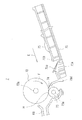
次に、本発明の給紙装置の第1実施形態である手差し装置7について詳しく説明する。図2は、手差し装置7を模式的に示す側面図である。
Next, the
図2に示すように、手差しトレイ71は、その先端部分71aが下方となるように傾斜して配置されており、その先端部分71aには、第1傾斜当接部71b、第2傾斜当接部71c、及び第3傾斜当接部71dが記録用紙の給紙方向Eの上流側から順次設けられている。手差しトレイ71の上面には、記録用紙を挟み込んでガイドする一対のガイド板75が設けられている。各ガイド板75は、給紙方向Eと直交する方向に移動可能に設けられて、図示しない機構により手差しトレイ71の中心に対して対称に連動して移動され、該各ガイド板75の間に挟み込まれた記録用紙の中心を手差しトレイ71の中心に一致させる。
As shown in FIG. 2, the
手差しトレイ71の先端部分71aの第3傾斜当接部71dの上方に給紙ローラ72が配置され、給紙ローラ72の下側に分離ローラ73が配置されている。分離ローラ73は、その軸73aが給紙ローラ72の駆動軸72aと平行であり、バネ(図示せず)により分離ローラ73の軸73aの軸受け(図示せず)が給紙ローラ72の側に付勢されて、分離ローラ73が給紙ローラ72に圧接され、給紙ローラ72と分離ローラ73との間にニップ域Hが形成されている。
The
第3傾斜当接部71dは、その上端部に用紙案内部材74が固定され、用紙案内部材74が給紙ローラ72の表面へと延在し、用紙案内部材74の先端が給紙ローラ72の表面に接触するか又はその表面より僅かに離間している。
A
図3は、同手差し装置7周りを模式的に示す平面図である。図4は、手差し装置7周りを拡大した具体的構成を示す側面図である。図3に示したように、手差し装置7において、手差しトレイ71は給紙方向Eと直交する方向(以下、横幅方向ともいう)に長い長方形状に形成される。手差しトレイ71の給紙方向E側の長さは、小サイズの記録用紙、例えばA6サイズの記録用紙の長さ近傍に設定される。手差しトレイ71の上面はほぼ平面に形成され、この平面が記録用紙を載置する載置面71gとなる。図4に示すように、この載置面71gに小サイズの記録用紙Psを載置したとき、記録用紙Psの給紙方向E上流側の端部(以下、後端部ともいう)は、手差しトレイ71の後端部に位置する。また、前記載置面71gには、前記一対のガイド板75が設けられ、このガイド板75により載置面71g上に記録用紙の中心を横幅方向の中心線l上に位置付ける構成である。
FIG. 3 is a plan view schematically showing the periphery of the
更に、前記手差しトレイ71の給紙方向Eの上流側には、長方形状に形成された拡張トレイ(拡張用紙載置台)80が配置される。拡張トレイ80は、その給紙方向E下流側の端部(以下、前端部ともいう)に、給紙方向E側に突出した形状の2つの接続部80a、80bを有する。この2つの接続部80a、80bは、拡張トレイ80の左端部及び右端部(給紙方向Eと直交する方向の一端部及び他端部)に形成され、手差しトレイ71の後端部に形成した軸支点(図示せず)に回動可能に軸支される。前記2つの接続部80a、80bには、図4にも示したように、上方に盛り上がる形状の盛上り部80c,80dが形成されている。前記拡張トレイ80の上面は、前記盛上り部80c,80dを除いて平面に形成され、この平面が大記録用紙の後部を載置する載置面80eとなる。
Further, on the upstream side of the
図3において、給紙ローラ72は、手差しトレイ71の給紙方向Eの下流端近傍に配置される。また、この給紙ローラ72は、その中心が手差しトレイ71の中心線lの延長線上に位置している。
In FIG. 3, the
図4は、手差しトレイ71及び拡張トレイ80を開いた状態を示している。手差しトレイ71は、詳示しないが、その下端部が画像形成装置1の本体側壁を形成する側壁1aに回動可能に軸支されていて、手差しトレイ71が画像形成装置1の側壁1a内に収容される閉位置と、この閉位置から手差しトレイ71を軸支点を中心に図4で時計方向に回動させた図示の開位置とに位置付けられる。
FIG. 4 shows a state where the
一方、拡張トレイ80は手差しトレイ71の直上方に重ねて位置する収納位置と、拡張トレイ80を軸支点を中心に図4で時計方向に回動させて、手差しトレイ71と拡張トレイ80とで連続した載置面を形成する図示の拡張位置とに位置付けられる。
On the other hand, the
手差し装置7を使用して記録用紙を給紙する場合には、手差しトレイ71を図示の開位置に位置付け、更に拡張トレイ80を収納位置から拡張位置に位置付ける。この状態において、小サイズの記録用紙Psを手差しトレイ71の載置面71gに載置する。一方、載置する用紙の後端部が手差しトレイ71の後端部を超える大サイズの記録用紙Plの場合には、この大サイズの記録用紙Plの前部を手差しトレイ71の載置面71gに載置し、その後部を拡張トレイ80の載置面80eに載置する。このとき、大サイズの記録用紙Plの後部は、拡張トレイ80の2つの接続部80a,8bに形成した盛上り部80c、80dに当接して上方に持ち上げられた状態で、載置面80eに載置される。
When recording paper is fed using the
図4から判るように、手差しトレイ71は、図示の開位置にあるとき、その後端部が先端部の軸支点(図示せず)よりも上方に位置して、手差しトレイ71の全体が給紙方向Eの下流側に向って傾斜角度θ1で傾斜するよう位置付けられる。従って、手差しトレイ71の載置面71gに小サイズの記録用紙Psを載置した場合には、記録用紙Psは自重で給紙方向Eの下流側に向って移動する。
As can be seen from FIG. 4, when the
また、拡張トレイ80も、図示の拡張位置にあるとき、その後端部が先端部の軸支点(図示せず)よりも上方に位置して、拡張トレイ80の全体が給紙方向Eの下流側に向って傾斜角度θ2で傾斜するよう位置付けられる。この拡張トレイ80の傾斜角度θ2は、前記手差しトレイ71の傾斜角度θ1とは異なって、手差しトレイ71の傾斜角度θ1よりも大きい角度(θ2>θ1)に設定されている。
When the
図4に示したように、前記手差しトレイ71の前端部近傍には、この前端部に対向して用紙検出部90が配置される。この用紙検出部90は、図3に示したように、給紙ローラ72の側方(給紙方向Eと直交する方向)に配置され、用紙有無検知アクチュエータ(動作片)91を有している。
As shown in FIG. 4, near the front end of the
用紙有無検知アクチュエータ91は、図5に拡大詳示するように、く字状に曲がったく字状板91aと、四角形状の連結板91bと、付勢バネ91cとから成る。く字状板91aは、給紙方向Eとほぼ平行配置された水平板91dと、この水平板91dの給紙方向Eの上流側端部から上方に立上る立上り板91eとからなり、立上り板91eの下端部近傍に前記手差しトレイ71上の記録用紙Ps、Plの先端部が自重等により当接する。く字状板91aの水平板91dは、給紙方向Eの下流側端部が画像形成装置1本体に設けた軸92に固定されている。また、連結板91bもその下端部が前記軸92に連結され、その上端部には給紙方向E下流側に開いた切欠部91fが形成されている。付勢バネ91cは、前記切欠部91fと画像形成装置1本体との間に縮装されている。
As shown in enlarged detail in FIG. 5, the paper presence /
前記用紙有無検知アクチュエータ91では、付勢バネ91cの付勢力(所定圧力)により、連結板91bが軸92を中心に給紙方向Eの上流側に向って回動し、これに伴い軸92が時計方向に回動して、く字状板91aが給紙方向Eの上流側に向って回動し、手差しトレイ71上の記録用紙Ps、Plの先端部を給紙方向Eの上流側に向って押し返す。
In the paper presence /
手差しトレイ71の載置面71gに記録用紙Ps、Plが無いとき、用紙有無検知アクチュエータ91のく字状板91aは付勢バネ91cの付勢力により給紙方向Eの上流側に向って回動しきった初期位置に位置付けられる。一方、手差しトレイ71の載置面71gに小サイズの記録用紙Psが多数有るときや大サイズの記録用紙Plが有るときには、く字状板91aは記録用紙Psの自重による給紙方向E下流側への押圧を受けて、付勢バネ91cを縮小させながら給紙方向E下流側に向って回動し、前記初期位置から外れることになる。用紙検出部90は、前記用紙有無検知アクチュエータ91のく字状板91aの位置を検出する位置センサ(図示せず)を有し、く字状板91aが前記初期位置にあるとき手差しトレイ71の載置面71gに記録用紙Ps、Plは無いと検出し、初期位置から外れたとき記録用紙Ps、Plは有ると検出する。
When there is no recording paper Ps, Pl on the mounting
前記用紙有無検知アクチュエータ91において、く字状板91aの動作量、すなわち、前記初期位置から、記録用紙Ps、Plの自重による給紙方向E下流側への押圧により付勢バネ91cを完全に縮小させた状態にく字状板91aが回動した押圧位置までの移動量は、例えば2mm以下の1、5mm程度に設定される。
In the paper presence /
そして、図3に示したように、手差しトレイ71の後端部近傍、すなわち、手差しトレイ71と拡張トレイ80との接続部近傍には、載置面71gに載置された小サイズの記録用紙Psの給紙方向E上流側への移動を規制する2つの規制部材100が配置される。この規制部材100は、拡張トレイ80の2つの接続部80a、80b同士が給紙方向Eと直交する方向に挟む空間に位置している。また、2つの規制部材100は、手差しトレイ71の中心線lを挟んで左右方向(給紙方向Eと直交する方向)に1つずつ配置される。従って、2つの規制部材100は、中心線l上の給紙ローラ72を挟んで左右対称に位置している。また、この2つの規制部材100は、最小横幅の記録用紙Psが一対のガイド板75により中心線l上に位置付けられたとき、この記録用紙Psの横幅内に位置するように配置されている。更に、一方の規制部材100は、用紙有無検知アクチュエータ91の配置位置を給紙方向E上流側に向って延ばした線上に位置している。
As shown in FIG. 3, near the rear end of the
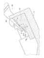
前記2つの規制部材100は、相互に同一構造である。図6は規制部材100周りを拡大した側断面図を示す。
The two regulating
図6において、規制部材100は、多数の刃が給紙方向E側に連続的に直線上に並んでいて、のこぎり形状に形成される。多数の刃の各々は、給紙方向E側の長さが異なる種々の記録用紙Psの後端部が給紙方向E上流側に移動するのを規制する規制部101を構成している。各規制部101は、手差しトレイ71が傾斜角度θ1で傾斜した状態においてほぼ垂直方向に切り立つ切立面101aと、この切立面101aの頂点から斜め下後方に降りる後斜面101bとを有する。切立面101aは、手差しトレイ71上の記録用紙Psの後端に対峙して、記録用紙Psが給紙方向E上流側に移動したとき、その記録用紙Psの後端面が切立面101aに当接して、その給紙方向E上流側への移動を規制、阻止する機能を有する。
In FIG. 6, the regulating
前記多数の規制部101は、手差しトレイ71の載置面71gからの高さh、すなわち、載置面71gから切立面101aの頂点までの長さが相互に異なり、給紙方向E上流側に位置する規制部101ほど前記高さhが高くなるように配置されている。
The plurality of regulating
前記多数の規制部101において、相隣る2つの規制部101間の離隔S、すなわち、切立面101aの頂点同士の離隔は、前記用紙有無検知アクチュエータ91のく字状板91aの初期位置から押圧位置までの移動量未満の長さに設定される。例えば、前記用紙有無検知アクチュエータ91のく字状板91aの移動量が2mmに設定されている場合には、その2mm未満の長さ、例えば1.2mmに設定される。尚、この離隔Sは、相隣る2つの規制部101間同士で同一長さ(等ピッチ)に設定する必要はなく、要は、前記く字状板91aの移動量未満の長さに設定すれば良い。
In the large number of restricting
更に、相隣る2つの規制部101間において、切立面101aの頂点同士の高さhの差dは、手差しトレイ71に載置される記録用紙Psの2枚程度の厚さに設定される。
Further, the difference d between the heights h of the apexes of the
前記規制部材100において、その給紙方向E側の長さ、すなわち、多数の規制部101全体の長さは、例えば本実施形態では15mm程度に設定されている。
In the regulating
尚、図6では、規制部101を15個配置する場合を例示したが、その配置個数は適宜設定可能である。
Although FIG. 6 illustrates a case where fifteen regulating
以上により、本実施形態では、手差し装置7を使用して小サイズの記録用紙Psを画像形成装置1内部に供給する場合には、手差しトレイ71を開位置に、拡張トレイ80を拡張位置に位置付け、この状態で、記録用紙Psを手差しトレイ71の載置面71gに載置する。
As described above, in the present embodiment, when the small-sized recording paper Ps is supplied into the
この状態において、記録用紙Psが多数枚のときには、手差しトレイ71が傾斜角度θ1で下流側に向って傾斜しているので、記録用紙Psはその自重により給紙方向E下流側に移動する。このため、用紙有無検知アクチュエータ91では、く字状板91aが記録用紙Psの自重による給紙方向E下流側の押圧を受けて、付勢バネ91cの付勢力に抗して給紙方向E下流側に回動し、初期位置から外れることになる。従って、用紙検出部90は、手差しトレイ71に記録用紙Psが有ると検出している。この状態では、記録用紙Psの後端部は、手差しトレイ71の後端部において、規制部材100の多数の規制部101の配置範囲内に位置している。
In this state, when the number of recording sheets Ps is large, since the
一方、手差しトレイ71上の記録用紙Psが例えば1枚又は2枚となり、その記録用紙Psの自重による給紙方向E下流側への押圧が用紙有無検知アクチュエータ91の付勢バネ91cの付勢力よりも小さくなった場合には、用紙有無検知アクチュエータ91のく字状板91aが初期位置に向って給紙方向E上流側に回動し、記録用紙Psを給紙方向E上流側に押し戻す状況となる。しかし、記録用紙Psの後端部が多数の規制部101のうち何れか1つの規制部101の切立面101aに当接すると、それ以上給紙方向E上流側への移動がその規制部101により規制、阻止されて、用紙有無検知アクチュエータ91は初期位置にまで移動することはない。従って、用紙検出部90は、手差しトレイ71に記録用紙Psが有ると確実に正しく検出する。
On the other hand, the number of recording sheets Ps on the
ここで、規制部材100は複数の規制部101からなり、更に、それら規制部101の手差しトレイ71の載置面71gからの高さhが給紙方向E上流側に向かうに従って高くなるように配置されている。従って、給紙方向E方向に長さの異なる複数種の記録用紙Psが手差しトレイ71の載置面71gに選択的に載置されても、その載置された記録用紙Psの後端部は、複数の規制部101のうち、その記録用紙Psの後端部から給紙方向E上流側に最初に位置している直近の規制部101の切立面101aの頂点近傍(1つ手前の規制部101との高さhの差異dの部分)に確実に当接し、係止されるので、その記録用紙Psの載置毎に規制部材100を従来のように給紙方向Eの上流側又は下流側に移動、調整する必要がない。
Here, the restricting
従って、手差しトレイ71に載置される記録用紙Psが、例えば、はがき等の定形サイズの用紙であっても公差(例えば1.5mm程度)がある場合や、載置する複数の記録用紙Ps間で給紙方向E側に多少の位置ずれが生じてしまっている場合、更には、給紙方向Eの長さが異なる種々のカスタマイズされた用紙が選択的に載置される場合であっても、それら記録用紙Psが1枚又は2枚程度であっても、記録用紙Psが載置面71gに有りと正しく検出することが可能である。
Therefore, even if the recording paper Ps placed on the
しかも、複数の規制部101のうち何れかの規制部101の切立面101aが記録用紙Psの後端面と当接して、その給紙方向E上流側への移動を阻止しているので、記録用紙Psが手差しトレイ71の載置面71gから若干浮いた状態であっても、従来のように載置面に摩擦部材を配置して用紙下面との摩擦力で移動を抑制する構成に比べて、記録用紙Psが給紙方向E上流側に移動するのを確実に阻止することが可能である。
In addition, since the
尚、手差しトレイ71に記録用紙Psが無い場合には、用紙有無検知アクチュエータ91のく字状板91aが付勢バネ91cの付勢力により初期位置に位置付けられるので、用紙検出部90は手差しトレイ71に記録用紙Psは無いと正しく検出する。
When there is no recording paper Ps in the
本実施形態では、規制部材100は手差しトレイ71の後端部、すなわち、手差しトレイ71と拡張トレイ80との接続部周りに配置され、且つ拡張トレイ80の傾斜角度θ2が手差しトレイ71の傾斜角度θ1よりも大きく(θ2>θ1)設定されている。従って、手差しトレイ71の載置面71gと拡張トレイ80の載置面80eに跨って大サイズの記録用紙Plを載置した場合には、図4から判るように、その記録用紙Plの下方には、前記手差しトレイ71と拡張トレイ80との接続部周りと記録用紙Plとで囲む空き空間Pが生じ、この空き空間Pに規制部材100が位置することになる。従って、大サイズの記録用紙Plの給紙に際して、記録用紙Plが給紙方向E側に移動する動作に規制部材100が干渉することはない。よって、規制部材100を取り外すなどの手動操作を要することなく、大サイズの記録用紙Plを簡単に給紙することが可能である。
In the present embodiment, the regulating
尚、大サイズの記録用紙Plを載置した場合には、その自重が小サイズの記録用紙Psよりも重いため、記録用紙Plが1枚又は2枚であっても、その自重により用紙有無検知アクチュエータ91のく字状板91aが付勢バネ91cの付勢力に抗して給紙方向E下流側に回動するため、初期位置から外れることになる。従って、用紙検出部90は大サイズの記録用紙Plが1枚又は2枚であっても載置されていると正しく検出する。
When a large-sized recording sheet Pl is placed, its own weight is heavier than that of the small-sized recording sheet Ps. Therefore, even if the recording sheet Pl is one or two sheets, the presence or absence of the sheet is detected by its own weight. Since the V-shaped
また、本実施形態では、規制部材100の複数の規制部101において、相隣る規制部101同士間の離隔は、用紙有無検知アクチュエータ91の動作量、すなわち、く字状板91aの押圧位置から初期位置までの移動量(例えば2mm)未満の長さ(例えば1.2mm)に設定されている。従って、たとえ用紙有無検知アクチュエータ91のく字状板91aが付勢バネ91cにより記録用紙Psを給紙方向E上流側に押し戻しても、く字状板91aが初期位置に達する途中の段階で、記録用紙Psの後端部は複数の規制部101の何れか1つの切立面101aに係止して、給紙方向E上流側へのそれ以上の移動が阻止される。従って、用紙有無検知アクチュエータ91のく字状板91aは初期位置に達せず、用紙検出部90は手差しトレイ71上に記録用紙Psは有ると正しく検出する。
Further, in the present embodiment, in the plurality of restricting
更に、本実施形態では、2つの規制部材100は、手差しトレイ71に載置された小サイズの記録用紙Psの横幅内において、中心線lを挟んで左右両側に配置されている。従って、用紙有無検知アクチュエータ91が前記中心線lからずれた位置にて記録用紙Psの先端部を押し戻しても、記録用紙Psは前記2つの規制部材100により中心線lを挟んで左右対称な位置に位置付けられ、左方又は右方に位置ズレを生じることが抑制される。
Further, in the present embodiment, the two regulating
(実施形態2)
図7は実施形態2の給紙装置の要部を示す。
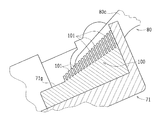
(Embodiment 2)
FIG. 7 shows a main part of the sheet feeding device according to the second embodiment.
前記実施形態1では、規制部材100をのこぎり状に形成したが、本実施形態では、櫛状に形成したものである。
In the first embodiment, the regulating
すなわち、図7に示した規制部材100では、給紙方向E上流側に向って一列状に延びる複数の櫛を手差しトレイ71の後端部に設け、それらの櫛を複数の規制部101としたものである。複数の規制部101は、各々、載置面71gから上方に延びる長方形状に形成され、それらの載置面71gからの高さが給紙方向E上流側に向うに従って高くなるように配置されていることは、前記実施形態1と同様である。
That is, in the regulating
(実施形態3)
図8は実施形態3の給紙装置の要部を示す。
(Embodiment 3)
FIG. 8 shows a main part of the sheet feeding device according to the third embodiment.
本実施形態では、規制部材100をブラシ状に形成したものである。すなわち、図8では、載置面71gから上方に延びる多数の線状の毛材を給紙方向E側及び横幅方向に配置し、それら多数の毛材を多数の規制部101として、それら多数の規制部101を、載置面71gからの高さが給紙方向E上流側に向うに従って高くなるように配置したものである。
In the present embodiment, the regulating
本実施形態では、規制部101が給紙方向E上流側に向けて多数個配置されているので、手差しトレイ71に載置された記録用紙Psの給紙方向E上流側への押し戻し量を最小限に抑制することが可能である。
In the present embodiment, since a large number of the regulating
尚、以上の説明では、規制部材100をのこぎり状、櫛状、ブラシ状としたが、その他、階段状や連続する複数のリブ状としても良い。更に、スポンジや高摩擦シート、マジックテープ(登録商標)を使用して、それらの形状を給紙方向E上流側に向うに従って高くなるように構成しても良い。
In the above description, the regulating
また、以上の実施形態では、手差し装置7に本発明を適用したが、その他、原稿読取り装置2や原稿搬送装置3に適用して、これらに載置される原稿用紙の有無検出を正しく行うようにしても良いのは勿論である。
In the above embodiment, the present invention is applied to the
本発明は、その精神又は主要な特徴から逸脱することなく、他の種々な形で実施することができる。そのため、上述の実施形態は例示に過ぎず、限定的に解釈してはならない。本発明の特許請求の範囲の均等範囲に属する変形や変更は、全て本発明の範囲内のものである。 The present invention may be embodied in various other forms without departing from its spirit or essential characteristics. Therefore, the above-described embodiment is merely an example and should not be construed as limiting. All modifications and changes belonging to the equivalent scope of the claims of the present invention are within the scope of the present invention.
本発明は、給紙装置として、用紙載置台上に配置する規制部材の位置を変更、調整したり、取り外すなどの手動操作を何ら要することなく、用紙載置台上の用紙が例えば1枚又は2枚程度になっても、確実に用紙載置台に用紙有りと正しく検出することが可能であるので、給紙装置及びこれを備えた画像形成装置に適用して、有用である。 The present invention provides, as a paper feeding device, one sheet or two sheets of paper on a paper mounting table without any manual operation such as changing, adjusting, or removing the position of a regulating member disposed on the paper mounting table. Even when the number of sheets is reduced, it is possible to reliably detect that there is a sheet on the sheet mounting table, and thus the present invention is useful when applied to a sheet feeding device and an image forming apparatus including the same.
1 画像形成装置
4 印刷部(画像形成部)
7 手差し装置(給紙装置)
71 手差しトレイ(用紙載置台)
71g 載置面
E 給紙方向
72 給紙ローラ
8 用紙搬送部(取込部)
80 拡張トレイ(拡張用紙載置台)
80a 接続部
80e 載置面
90 用紙検出部
91 用紙有無検出アクチュエータ(動作片)
91a く字状板
91c 付勢バネ
Ps 小サイズの記録用紙(用紙)
Pl 大サイズの記録用紙(用紙)
100 規制部材
101 規制部
101a 切立面
1
7 Manual feeder (paper feeder)
71 Bypass tray (paper loading table)
71g Loading surface E
80 Expansion tray (expansion paper table)
91a
Pl Large-size recording paper (paper)
100 regulating
Claims (7)
載置面に用紙が載置され、前記用紙を前記画像形成装置に供給する給紙方向の下流側に向かって下方に傾斜する用紙載置台と、
前記用紙の給紙方向下流端を前記給紙方向上流側に所定圧力で押す動作片を有し、該動作片の動作により前記用紙の有無を検出する用紙検出部と、
前記用紙載置台の前記給紙方向上流側の端部近傍に配置され、前記用紙の前記給紙方向上流側への移動を規制する規制部材と、を有し、
前記規制部材は、前記用紙載置台の載置面からの高さが異なる複数の規制部を有し、
前記複数の規制部は、前記高さが前記給紙方向の上流側に向かうに従って高くなるように配置されている
ことを特徴とする給紙装置。 A paper supply device for supplying paper to the image forming apparatus,
A sheet placing table on which a sheet is placed, and which is inclined downward toward a downstream side in a sheet feeding direction for supplying the sheet to the image forming apparatus;
A sheet detecting unit that has an operation piece that presses the downstream end of the sheet in the sheet feeding direction at a predetermined pressure on the upstream side in the sheet feeding direction, and detects the presence or absence of the sheet by the operation of the operation piece;
A regulating member disposed near an end of the paper mounting table on the upstream side in the paper supply direction, and a regulating member for regulating movement of the paper to the upstream side in the paper supply direction,
The regulating member has a plurality of regulating portions having different heights from the placing surface of the paper placing table,
The paper feeding device according to claim 1, wherein the plurality of restricting portions are arranged such that the height increases toward an upstream side in the paper feeding direction.
前記手差しトレイには、前記給紙方向に長さの異なる複数種の用紙が選択的に載置される
ことを特徴とする請求項1記載の給紙装置。 The paper mounting table is a manual feed tray,
The sheet feeding device according to claim 1, wherein a plurality of types of sheets having different lengths in the sheet feeding direction are selectively placed on the manual feed tray.
前記拡張用紙載置台の前記傾斜の角度は、前記用紙載置台の前記傾斜の角度よりも大きく設定されており、
前記規制部材は、前記用紙載置台と前記拡張用紙載置台との接続部近傍の位置に配置されている
ことを特徴とする請求項1又は2記載の給紙装置。 At the end of the paper mounting table on the upstream side in the paper feeding direction, an extended paper mounting table for large paper that is inclined downward toward the downstream side in the paper feeding direction is connected,
The angle of the inclination of the expansion sheet mounting table is set to be larger than the angle of the inclination of the sheet mounting table,
The paper feeder according to claim 1, wherein the restricting member is disposed at a position near a connection between the paper mounting table and the extended paper mounting table. 4.
ことを特徴とする請求項1から請求項3の何れか1項に記載の給紙装置。 The said restriction member is arrange | positioned in the width | variety of the direction orthogonal to the said paper feed direction of the said paper, and is arrange | positioned on both sides on either side of the center of the said width. 2. The paper feeding device according to claim 1.
ことを特徴とする請求項1から請求項4の何れか1項に記載の給紙装置。 The distance between the adjacent regulating portions of the plurality of regulating portions is set to a length less than the amount of movement of the operation piece toward the upstream side in the sheet feeding direction. The paper feeding device according to claim 4.
ことを特徴とする請求項1から請求項5の何れか1項に記載の給紙装置。 The paper feeder according to any one of claims 1 to 5, wherein the plurality of regulating portions are formed in a step shape, a comb shape, or a brush shape.
前記用紙載置台に載置された用紙を内部に取り込む取込部と、
前記取込部により取り込んだ用紙に画像を形成する画像形成部と、を備えた
ことを特徴とする画像形成装置。 A sheet feeding device according to any one of claims 1 to 6,
An intake unit that takes in the sheet placed on the sheet placing table,
An image forming apparatus comprising: an image forming unit that forms an image on a sheet captured by the capturing unit.
Priority Applications (3)
| Application Number | Priority Date | Filing Date | Title |
|---|---|---|---|
| JP2018126997A JP7064983B2 (en) | 2018-07-03 | 2018-07-03 | Paper feed device and image forming device equipped with this |
| US16/447,205 US20200010291A1 (en) | 2018-07-03 | 2019-06-20 | Sheet feeder and image forming apparatus including the same |
| CN201910592663.XA CN110668214A (en) | 2018-07-03 | 2019-07-03 | Sheet feeding device and image forming apparatus including the same |
Applications Claiming Priority (1)
| Application Number | Priority Date | Filing Date | Title |
|---|---|---|---|
| JP2018126997A JP7064983B2 (en) | 2018-07-03 | 2018-07-03 | Paper feed device and image forming device equipped with this |
Publications (2)
| Publication Number | Publication Date |
|---|---|
| JP2020007061A true JP2020007061A (en) | 2020-01-16 |
| JP7064983B2 JP7064983B2 (en) | 2022-05-11 |
Family
ID=69068604
Family Applications (1)
| Application Number | Title | Priority Date | Filing Date |
|---|---|---|---|
| JP2018126997A Active JP7064983B2 (en) | 2018-07-03 | 2018-07-03 | Paper feed device and image forming device equipped with this |
Country Status (3)
| Country | Link |
|---|---|
| US (1) | US20200010291A1 (en) |
| JP (1) | JP7064983B2 (en) |
| CN (1) | CN110668214A (en) |
Families Citing this family (3)
| Publication number | Priority date | Publication date | Assignee | Title |
|---|---|---|---|---|
| JP7195460B2 (en) * | 2020-01-27 | 2022-12-23 | 富士通フロンテック株式会社 | Paper sheet storage device and paper sheet handling device |
| JP2022141026A (en) * | 2021-03-15 | 2022-09-29 | 京セラドキュメントソリューションズ株式会社 | Image forming apparatus |
| JP2022152383A (en) * | 2021-03-29 | 2022-10-12 | 富士フイルムビジネスイノベーション株式会社 | Manual paper-feeding device, and image forming apparatus |
Citations (3)
| Publication number | Priority date | Publication date | Assignee | Title |
|---|---|---|---|---|
| JP2002370836A (en) * | 2001-06-13 | 2002-12-24 | Minolta Co Ltd | Paper feeder |
| JP2008260621A (en) * | 2007-04-13 | 2008-10-30 | Ricoh Co Ltd | Automatic document carrying device and image reader |
| JP2017077930A (en) * | 2015-10-19 | 2017-04-27 | キヤノン株式会社 | Sheet feeding device and image formation device |
Family Cites Families (8)
| Publication number | Priority date | Publication date | Assignee | Title |
|---|---|---|---|---|
| JPS5421849A (en) * | 1977-07-20 | 1979-02-19 | Kopia Kk | Waste paper receiving apparatus for copier |
| JPS61287631A (en) * | 1985-06-14 | 1986-12-18 | Konishiroku Photo Ind Co Ltd | Sheet material feeding cassette |
| JP2000025960A (en) * | 1998-07-10 | 2000-01-25 | Ricoh Co Ltd | Paper feed tray |
| RU2002122760A (en) * | 2000-01-26 | 2004-04-10 | Кба-Жиори С.А. (Ch) | METHOD AND DEVICE FOR REGISTRATION OF PAPER SHEETS |
| JP4193069B2 (en) * | 2005-08-31 | 2008-12-10 | ブラザー工業株式会社 | Paper feeding device and image recording apparatus having the same |
| JP2010030772A (en) * | 2008-07-31 | 2010-02-12 | Canon Electronics Inc | Sheet feeder |
| JP6388159B2 (en) * | 2014-11-14 | 2018-09-12 | 富士ゼロックス株式会社 | Image forming apparatus |
| JP6277996B2 (en) * | 2015-05-15 | 2018-02-14 | 京セラドキュメントソリューションズ株式会社 | Sheet supply apparatus and image forming apparatus having the same |
-
2018
- 2018-07-03 JP JP2018126997A patent/JP7064983B2/en active Active
-
2019
- 2019-06-20 US US16/447,205 patent/US20200010291A1/en not_active Abandoned
- 2019-07-03 CN CN201910592663.XA patent/CN110668214A/en active Pending
Patent Citations (3)
| Publication number | Priority date | Publication date | Assignee | Title |
|---|---|---|---|---|
| JP2002370836A (en) * | 2001-06-13 | 2002-12-24 | Minolta Co Ltd | Paper feeder |
| JP2008260621A (en) * | 2007-04-13 | 2008-10-30 | Ricoh Co Ltd | Automatic document carrying device and image reader |
| JP2017077930A (en) * | 2015-10-19 | 2017-04-27 | キヤノン株式会社 | Sheet feeding device and image formation device |
Also Published As
| Publication number | Publication date |
|---|---|
| JP7064983B2 (en) | 2022-05-11 |
| CN110668214A (en) | 2020-01-10 |
| US20200010291A1 (en) | 2020-01-09 |
Similar Documents
| Publication | Publication Date | Title |
|---|---|---|
| US20120080836A1 (en) | Sheet feeder and image forming apparatus including the same | |
| JP2020007061A (en) | Paper feeder, and image forming apparatus provided with the same | |
| JP5823454B2 (en) | Paper feeding device and image forming apparatus | |
| JP4598099B2 (en) | Image forming apparatus | |
| US9561917B2 (en) | Sheet feeding device and image forming apparatus | |
| US9611111B2 (en) | Sheet feeding device and image forming apparatus | |
| JP2014101178A (en) | Paper feeder, image reader including the same, and image formation apparatus | |
| EP2650732B1 (en) | Sheet loading device and image forming apparatus equipped with the same | |
| JP5156480B2 (en) | Image forming apparatus | |
| US20050001372A1 (en) | Sheet feeding apparatus and image forming apparatus | |
| US20200165085A1 (en) | Sheet feeding device and image forming apparatus incorporating the sheet feeding device | |
| JP2021172475A (en) | Sheet discharge device, and original feeder and image forming apparatus comprising the same | |
| JP2007217156A (en) | Sheet delivery mechanism and image forming device equipped with it | |
| JP4476135B2 (en) | Paper cassette | |
| CN110963324B (en) | Image forming apparatus with a toner supply device | |
| JP6354686B2 (en) | Sheet feeding apparatus and image forming apparatus provided with the same | |
| JP2023043589A (en) | Sheet feeding device and image forming apparatus including the same | |
| JP4569907B2 (en) | Medium conveying apparatus and image forming apparatus | |
| JP2018127300A (en) | Sheet stacking device and image formation device | |
| JP4188157B2 (en) | Image forming apparatus | |
| JP2023073920A (en) | image forming device | |
| JP4037296B2 (en) | Document feeder | |
| JP2022006884A (en) | Paper-feeding cassette and image forming device equipped therewith | |
| JP6758058B2 (en) | Paper feed device and image forming device | |
| JP6494440B2 (en) | Image reading apparatus and image forming apparatus |
Legal Events
| Date | Code | Title | Description |
|---|---|---|---|
| A621 | Written request for application examination |
Free format text: JAPANESE INTERMEDIATE CODE: A621 Effective date: 20210324 |
|
| A977 | Report on retrieval |
Free format text: JAPANESE INTERMEDIATE CODE: A971007 Effective date: 20220121 |
|
| A131 | Notification of reasons for refusal |
Free format text: JAPANESE INTERMEDIATE CODE: A131 Effective date: 20220201 |
|
| A521 | Request for written amendment filed |
Free format text: JAPANESE INTERMEDIATE CODE: A523 Effective date: 20220331 |
|
| TRDD | Decision of grant or rejection written | ||
| A01 | Written decision to grant a patent or to grant a registration (utility model) |
Free format text: JAPANESE INTERMEDIATE CODE: A01 Effective date: 20220405 |
|
| A61 | First payment of annual fees (during grant procedure) |
Free format text: JAPANESE INTERMEDIATE CODE: A61 Effective date: 20220425 |
|
| R150 | Certificate of patent or registration of utility model |
Ref document number: 7064983 Country of ref document: JP Free format text: JAPANESE INTERMEDIATE CODE: R150 |