JP6491992B2 - Trigger type liquid ejector - Google Patents

Trigger type liquid ejector Download PDF

Info

Publication number
JP6491992B2
JP6491992B2 JP2015215248A JP2015215248A JP6491992B2 JP 6491992 B2 JP6491992 B2 JP 6491992B2 JP 2015215248 A JP2015215248 A JP 2015215248A JP 2015215248 A JP2015215248 A JP 2015215248A JP 6491992 B2 JP6491992 B2 JP 6491992B2
Authority
JP
Japan
Prior art keywords
cylinder
plunger
storage
negative pressure
trigger
Prior art date
Legal status (The legal status is an assumption and is not a legal conclusion. Google has not performed a legal analysis and makes no representation as to the accuracy of the status listed.)
Active
Application number
JP2015215248A
Other languages
Japanese (ja)
Other versions
JP2017080723A (en
Inventor
角田 義幸
義幸 角田
桑原 和仁
和仁 桑原
Current Assignee (The listed assignees may be inaccurate. Google has not performed a legal analysis and makes no representation or warranty as to the accuracy of the list.)
Yoshino Kogyosho Co Ltd
Original Assignee
Yoshino Kogyosho Co Ltd
Priority date (The priority date is an assumption and is not a legal conclusion. Google has not performed a legal analysis and makes no representation as to the accuracy of the date listed.)
Filing date
Publication date
Application filed by Yoshino Kogyosho Co Ltd filed Critical Yoshino Kogyosho Co Ltd
Priority to JP2015215248A priority Critical patent/JP6491992B2/en
Publication of JP2017080723A publication Critical patent/JP2017080723A/en
Application granted granted Critical
Publication of JP6491992B2 publication Critical patent/JP6491992B2/en
Active legal-status Critical Current
Anticipated expiration legal-status Critical

Links

Images

Description

本発明は、トリガー式液体噴出器に関するものである。   The present invention relates to a trigger type liquid ejector.

ノズルの下方に延びるトリガー部の操作により、容器体から液体を吸い上げてノズルから吐出するトリガー式液体噴出器が知られている(例えば下記特許文献1)。
従来のトリガー式液体噴出器では、容器体と連通する縦供給筒部の上部に、前方に向けて延びる射出筒部が設けられている。射出筒部の先端側にはノズルが付設されている。射出筒部の下方には、トリガー部の操作により作動するシリンダが配置されている。そして、トリガー部の操作を行うことで、縦供給筒部からシリンダ内に液体を吸い上げることができるとともに、その液体を射出筒部からノズルを経て前方に噴射(噴出)させることができる。
2. Description of the Related Art A trigger type liquid ejector that sucks up liquid from a container body and discharges it from a nozzle by operating a trigger portion extending below the nozzle is known (for example, Patent Document 1 below).
In a conventional trigger type liquid ejector, an injection cylinder portion extending toward the front is provided on an upper portion of a vertical supply cylinder portion communicating with a container body. A nozzle is attached to the distal end side of the injection tube portion. A cylinder that is operated by operating the trigger portion is disposed below the injection cylinder portion. And by operating the trigger part, the liquid can be sucked into the cylinder from the vertical supply cylinder part, and the liquid can be ejected (spouted) forward from the injection cylinder part through the nozzle.

特許第3781904号公報Japanese Patent No. 3789904

しかしながら、上記従来のトリガー式液体噴出器では、トリガー部を引くときにのみ液体が噴射される。したがって、例えば広い面積に対して液体を吹き付けるようなときには、何度もトリガー部を引く操作を繰り返す必要があり面倒である。   However, in the conventional trigger type liquid ejector, liquid is ejected only when the trigger portion is pulled. Therefore, for example, when the liquid is sprayed over a large area, it is necessary to repeat the operation of pulling the trigger portion many times, which is troublesome.

本発明は、このような事情に鑑みてなされたものであって、その目的は、液体の連続噴射を可能にしたトリガー式液体噴出器を提供することである。   This invention is made | formed in view of such a situation, The objective is to provide the trigger type | mold liquid ejector which enabled the continuous injection of the liquid.

前記課題を解決するために、本発明は以下の手段を提案している。
本発明に係るトリガー式液体噴出器は、液体が収容された容器体に装着される噴出器本体と、前記噴出器本体の前方側に配置され、液体を前方に向けて噴射する噴出孔が形成されたノズル部材と、を備え、前記噴出器本体は、上下方向に延在し、前記容器体内の液体を吸上げる縦供給筒部と、前記縦供給筒部から前方に向けて延設され、内側が前記縦供給筒部の内部に連通した射出筒部と、前記射出筒部から下方に向けて延設され、前方付勢状態で後方に移動自在に配設されたトリガー部を有し、前記トリガー部の後方への移動によって、液体を前記縦供給筒部内から前記射出筒部内に導入させるとともに、前記射出筒部内から前記噴出孔側に向けて射出させるトリガー機構と、を備えるトリガー式液体噴出器であって、前記トリガー部の後方への移動によって、前記縦供給筒部内を通過した液体が内部に供給される貯留シリンダと、前記貯留シリンダ内にその中心軸線に沿う軸方向に移動自在に配設され、前記貯留シリンダ内への液体の供給に伴い前記軸方向のうちの一方側に向けて移動する貯留プランジャと、前記貯留プランジャに連結され、前記貯留プランジャの前記軸方向の移動に連係する負圧プランジャと、前記軸方向に沿って延びるとともに前記軸方向の他端開口と外部の連通が遮断され、内部に前記負圧プランジャが前記軸方向の一方側に向けて移動自在に収容された負圧シリンダと、を備えることを特徴とする。
In order to solve the above problems, the present invention proposes the following means.
The trigger type liquid ejector according to the present invention includes an ejector body mounted on a container body in which a liquid is accommodated, and an ejection hole that is disposed on the front side of the ejector body and ejects the liquid forward. A nozzle member, and the ejector body extends vertically and extends vertically from the vertical supply cylinder, the vertical supply cylinder that sucks up the liquid in the container body, An injection cylinder part whose inner side communicates with the inside of the vertical supply cylinder part, and a trigger part that extends downward from the injection cylinder part and is movably disposed rearward in a forward biased state, A trigger type liquid comprising: a trigger mechanism that causes the liquid to be introduced from the vertical supply cylinder part into the injection cylinder part by being moved rearward of the trigger part, and to be ejected from the injection cylinder part toward the ejection hole side. An ejector after the trigger And a storage cylinder in which the liquid that has passed through the vertical supply cylinder is supplied to the inside, and the storage cylinder is disposed in the storage cylinder so as to be movable in the axial direction along the central axis thereof. A storage plunger that moves toward one side of the axial direction in accordance with the supply of liquid, a negative pressure plunger that is connected to the storage plunger and is linked to the movement of the storage plunger in the axial direction, and the axial direction A negative pressure cylinder that extends along the other end and that is disconnected from the other end opening in the axial direction and that communicates with the outside, and in which the negative pressure plunger is movably accommodated toward one side in the axial direction. Features.

本発明によれば、液体が収容された容器体に装着した状態で、トリガー部を後方に引くと、容器体内の液体が吸い上げられて縦供給筒部内に導入され、縦供給筒部内を通過した液体が、射出筒部内を通じて噴出孔から噴射される一方、貯留シリンダ内にも導入される。液体の貯留シリンダ内への導入に伴い、貯留シリンダ内の貯留プランジャが、負圧シリンダ内の負圧プランジャとともに前記軸方向の一方側に向けて移動する。この際、負圧シリンダ内のうち、負圧プランジャより前記軸方向の他方側に位置する密閉空間が負圧になる。これにより、負圧プランジャおよび貯留プランジャに対して前記軸方向の他方側に向けた付勢力が作用する。
このように、トリガー部を引く操作を行う毎に、液体を噴出孔から噴射させつつ、貯留プランジャを前記軸方向の一方側に移動させて貯留シリンダ内に液体を溜める(充填する)ことができる。
そして、トリガー部を引く操作を止めると、縦供給筒部内への液体の供給が停止するが、負圧シリンダ内の負圧によって、負圧プランジャおよび貯留プランジャが一体に前記軸方向の他方側に向けて復元移動しはじめる。これにより、貯留シリンダ内に充填した液体が、貯留シリンダ内から噴出孔側に向けて押し出されることで、噴出孔から引き続き噴射させることができる。したがって、トリガー部を後方に引く操作を行ったときだけでなく、トリガー部を操作しない場合であっても液体を噴射させることができ、液体の連続噴射を行うことができる。
なお貯留プランジャが前記軸方向の他方側に向けて復元移動する際、再びトリガー部を引かなければ、貯留プランジャは貯留シリンダにおける前記軸方向の他端まで移動するが、その前にトリガー部を引く操作を繰り返すこともできる。この場合、貯留プランジャが略一定の幅で前記軸方向の一方側への移動と他方側への移動とを繰り返し、全体としては徐々に前記軸方向の一方側へ移動する。これにより、貯留シリンダ内に徐々に液体が溜まっていく。
ところで、負圧プランジャおよび貯留プランジャを復元移動させるときに、負圧シリンダ内の負圧を利用するので、例えば、付勢部材など他の部材から作用する付勢力を利用しなくても、負圧プランジャおよび貯留プランジャを復元移動させることができる。これにより、構造の簡素化を図りつつ、負圧プランジャおよび貯留プランジャに推力を付与することができる。なお、一般的な付勢部材として、例えば金属スプリング等の利用が考えられるが、この種の付勢部材を使用しないことで、このトリガー式液体噴出器を合成樹脂材料のみによって形成することも可能になる。
According to the present invention, when the trigger part is pulled backward in a state where the liquid container is mounted on the container body, the liquid in the container body is sucked up and introduced into the vertical supply cylinder part and passed through the vertical supply cylinder part. While the liquid is ejected from the ejection hole through the inside of the ejection cylinder portion, it is also introduced into the storage cylinder. As the liquid is introduced into the storage cylinder, the storage plunger in the storage cylinder moves toward one side in the axial direction together with the negative pressure plunger in the negative pressure cylinder. At this time, in the negative pressure cylinder, the sealed space located on the other side in the axial direction from the negative pressure plunger becomes negative pressure. Thereby, the urging | biasing force toward the other side of the said axial direction acts with respect to a negative pressure plunger and a storage plunger.
In this way, each time the operation of pulling the trigger portion is performed, the storage plunger can be moved to one side in the axial direction while the liquid is ejected from the ejection hole, and the liquid can be stored (filled) in the storage cylinder. .
When the operation of pulling the trigger portion is stopped, the supply of liquid into the vertical supply cylinder portion is stopped, but the negative pressure plunger and the storage plunger are integrally moved to the other side in the axial direction by the negative pressure in the negative pressure cylinder. Start to move towards restoration. Thereby, the liquid filled in the storage cylinder can be continuously ejected from the ejection hole by being pushed out from the storage cylinder toward the ejection hole side. Therefore, the liquid can be ejected not only when the trigger part is pulled backward but also when the trigger part is not operated, and the liquid can be continuously ejected.
When the storage plunger is restored and moved toward the other side in the axial direction, if the trigger portion is not pulled again, the storage plunger moves to the other end in the axial direction of the storage cylinder, but the trigger portion is pulled before that. You can repeat the operation. In this case, the storage plunger repeats the movement toward the one side in the axial direction and the movement toward the other side with a substantially constant width, and as a whole, gradually moves toward the one side in the axial direction. Thereby, the liquid gradually accumulates in the storage cylinder.
By the way, when the negative pressure plunger and the storage plunger are restored and moved, the negative pressure in the negative pressure cylinder is used. For example, even if the biasing force acting from another member such as a biasing member is not used, the negative pressure The plunger and the storage plunger can be restored. Thereby, thrust can be given to a negative pressure plunger and a storage plunger, aiming at simplification of a structure. As a general urging member, use of, for example, a metal spring is conceivable, but by not using this type of urging member, it is possible to form this trigger type liquid ejector only with a synthetic resin material. become.

前記負圧プランジャの受圧面積は、前記貯留プランジャの受圧面積より大きくてもよい。   The pressure receiving area of the negative pressure plunger may be larger than the pressure receiving area of the storage plunger.

この場合、負圧プランジャの受圧面積が、貯留プランジャの受圧面積より大きいので、負圧シリンダ内の負圧によって、負圧プランジャおよび貯留プランジャが一体に復元移動するときに、負圧プランジャの受圧面積に応じて、負圧プランジャおよび貯留プランジャに大きな推力を付与することができる。これにより、負圧プランジャおよび貯留プランジャをスムーズに復元移動させることができる。   In this case, since the pressure receiving area of the negative pressure plunger is larger than the pressure receiving area of the storage plunger, when the negative pressure plunger and the storage plunger are integrally restored and moved by the negative pressure in the negative pressure cylinder, the pressure receiving area of the negative pressure plunger Accordingly, a large thrust can be applied to the negative pressure plunger and the storage plunger. Thereby, the negative pressure plunger and the storage plunger can be smoothly restored and moved.

前記貯留シリンダおよび前記負圧シリンダは、一体に形成されるとともに、前記貯留シリンダが、前記負圧シリンダの内側に配置された二重筒状に形成され、前記貯留プランジャおよび前記負圧プランジャは、一体に形成されるとともに、前記貯留プランジャが、前記負圧プランジャの内側に配置された二重筒状に形成されていてもよい。   The storage cylinder and the negative pressure cylinder are integrally formed, and the storage cylinder is formed in a double cylinder disposed inside the negative pressure cylinder, and the storage plunger and the negative pressure plunger are: While being formed integrally, the storage plunger may be formed in a double cylinder shape disposed inside the negative pressure plunger.

この場合、貯留シリンダおよび負圧シリンダが、一体に形成されるとともに、貯留プランジャおよび負圧プランジャが、一体に形成されているので、構造の簡素化を図ることができる。   In this case, since the storage cylinder and the negative pressure cylinder are integrally formed, and the storage plunger and the negative pressure plunger are integrally formed, the structure can be simplified.

前記貯留プランジャおよび前記負圧プランジャのうちの少なくとも一方に形成された被係止部から、前記軸方向の一方側に離れて配置された規制部を備え、前記規制部は、前記貯留プランジャおよび前記負圧プランジャが前記軸方向の一方側に向けて移動したときに、前記被係止部が前記軸方向の他方側から当接し、これらの両プランジャのこれ以上の前記軸方向の一方側に向けた移動を規制してもよい。   A restricting portion is disposed on one side in the axial direction from a locked portion formed on at least one of the storage plunger and the negative pressure plunger, and the restricting portion includes the storage plunger and the storage plunger. When the negative pressure plunger moves toward one side in the axial direction, the locked portion abuts from the other side in the axial direction, and further toward the one side in the axial direction beyond these plungers. The movement may be restricted.

この場合、貯留プランジャおよび負圧プランジャが前記軸方向の一方側に向けて移動するときに、被係止部と規制部とが当接することで、両プランジャの更なる移動が規制され、両プランジャの過度な移動を規制して、貯留シリンダ内に許容量以上の液体が充填されてしまうことを防止できる。これにより、貯留シリンダ内の圧力が過度に上昇することを防止でき、破損等の不具合が生じることを防止することができる。そのため、使い勝手が良く、液体の連続噴射を安心して行うことができる。   In this case, when the storage plunger and the negative pressure plunger move toward one side in the axial direction, the further movement of both plungers is restricted by the contact between the locked portion and the restriction portion, and both plungers Therefore, it is possible to prevent the storage cylinder from being filled with an excessive amount of liquid. Thereby, it can prevent that the pressure in a storage cylinder rises excessively, and it can prevent that malfunctions, such as breakage, arise. For this reason, it is easy to use, and the continuous ejection of liquid can be performed with peace of mind.

本発明によれば、トリガー部を後方に引く操作を行ったときだけでなく、トリガー部を操作しない場合であっても液体を噴射させることができ、液体の連続噴射を行うことができる。   According to the present invention, liquid can be ejected not only when the operation of pulling the trigger portion backward is performed but also when the trigger portion is not operated, and continuous liquid ejection can be performed.

本発明に係るトリガー式液体噴出器の第1実施形態を示す縦断面図である。It is a longitudinal section showing a 1st embodiment of a trigger type liquid ejector concerning the present invention. 図1に示すトリガー式液体噴出器を構成する噴出器本体を含む要部の拡大縦断面図である。It is an expanded vertical sectional view of the principal part containing the ejector main body which comprises the trigger type liquid ejector shown in FIG. 図1に示すトリガー式液体噴出器を構成するノズル部材を含む要部の拡大縦断面図である。FIG. 2 is an enlarged longitudinal sectional view of a main part including a nozzle member constituting the trigger type liquid ejector shown in FIG. 1. 図1に示すトリガー式液体噴出器において、トリガー部を後方側に引いて貯留プランジャおよび負圧プランジャを後方移動させた状態を示す縦断面図である。In the trigger type liquid ejector shown in FIG. 1, it is a longitudinal cross-sectional view which shows the state which pulled the trigger part back and moved the storage plunger and the negative pressure plunger back. 本発明に係るトリガー式液体噴出器の第2実施形態を示す縦断面図である。It is a longitudinal cross-sectional view which shows 2nd Embodiment of the trigger type liquid ejector which concerns on this invention. 図5に示すトリガー式液体噴出器を構成するノズル部材を含む要部の拡大縦断面図である。FIG. 6 is an enlarged longitudinal sectional view of a main part including a nozzle member constituting the trigger type liquid ejector shown in FIG. 5. 図5に示すトリガー式液体噴出器を構成する貯留シリンダ、貯留プランジャ、負圧プランジャ、負圧シリンダを含む要部の拡大縦断面図である。FIG. 6 is an enlarged longitudinal sectional view of a main part including a storage cylinder, a storage plunger, a negative pressure plunger, and a negative pressure cylinder constituting the trigger type liquid ejector shown in FIG. 5. 図5に示すトリガー式液体噴出器において、トリガー部を後方側に引いて貯留プランジャおよび負圧プランジャを後方移動させた状態を示す縦断面図である。In the trigger type liquid ejector shown in FIG. 5, it is a longitudinal cross-sectional view which shows the state which pulled the trigger part back and moved the storage plunger and the negative pressure plunger back. 本発明に係るトリガー式液体噴出器の変形例を示す要部の縦断面図である。(a)は、挿入治具を用いて、貯留プランジャおよび負圧プランジャを貯留シリンダ内および負圧シリンダ内に挿入し、かつ栓部材を貯留プランジャに装着する状態を示している。(b)は、貯留プランジャの閉塞壁が、貯留シリンダの前壁部に到達した後に、挿入治具を後方移動させる状態を示している。(c)は、本発明に係るトリガー式液体噴出器の変形例が完成した状態を示している。It is a longitudinal cross-sectional view of the principal part which shows the modification of the trigger type liquid ejector which concerns on this invention. (A) has shown the state which inserts a storage plunger and a negative pressure plunger in a storage cylinder and a negative pressure cylinder, and mounts a plug member on a storage plunger using an insertion jig. (B) has shown the state which moves an insertion jig | tool back after the obstruction | occlusion wall of a storage plunger reaches | attains the front wall part of a storage cylinder. (C) has shown the state which the modification of the trigger type | mold liquid ejector which concerns on this invention was completed.

(第1実施形態)
以下、本発明に係るトリガー式液体噴出器の第1実施形態について、図1から図4を参照して説明する。
図1に示すように、本実施形態のトリガー式液体噴出器1は、液体を収容する容器体Aに装着され、液体を吸上げる縦供給筒部10を有する噴出器本体2と、噴出孔4が形成され、噴出器本体2に装着されたノズル部材3と、を備えている。
なお、トリガー式液体噴出器1の各構成は、特に記載がなければ合成樹脂を用いた成型品とされている。
(First embodiment)
Hereinafter, a first embodiment of a trigger type liquid ejector according to the present invention will be described with reference to FIGS. 1 to 4.
As shown in FIG. 1, a trigger type liquid ejector 1 according to this embodiment is mounted on a container body A that contains a liquid, and includes an ejector body 2 having a vertical supply cylinder portion 10 that sucks the liquid, and an ejection hole 4. And a nozzle member 3 mounted on the ejector body 2.
Each component of the trigger type liquid ejector 1 is a molded product using a synthetic resin unless otherwise specified.

ここで、本実施形態では、縦供給筒部10の中心軸線を軸線O1とし、この軸線O1に沿って容器体A側を下側、その反対側を上側という。また、軸線O1に直交する一方向を前後方向といい、軸線O1方向および前後方向の双方向に直交する方向を左右方向という。   Here, in the present embodiment, the central axis of the vertical supply cylinder portion 10 is defined as an axis O1, and the container body A side is referred to as the lower side along the axis O1, and the opposite side is referred to as the upper side. One direction orthogonal to the axis O1 is referred to as the front-rear direction, and the direction orthogonal to the direction of the axis O1 and the front-rear direction is referred to as the left-right direction.

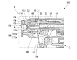
図2に示すように、噴出器本体2は、上下方向に延在する上記縦供給筒部10と、縦供給筒部10から前後方向に沿って延設され、内側が縦供給筒部10の内部に連通した射出筒部11と、を備え、左右方向から見た側面視でL字状に形成されている。
なお、前後方向のうち、縦供給筒部10から射出筒部11が延びる方向を前側或いは前方とし、その反対方向を後側或いは後方という。
As shown in FIG. 2, the ejector body 2 includes the vertical supply cylinder portion 10 extending in the vertical direction, and extends from the vertical supply cylinder portion 10 along the front-rear direction. And an injection cylinder portion 11 communicating with the inside, and is formed in an L shape in a side view as viewed from the left-right direction.
In the front-rear direction, the direction in which the injection cylinder part 11 extends from the vertical supply cylinder part 10 is referred to as the front side or the front side, and the opposite direction is referred to as the rear side or the rear side.

縦供給筒部10は、有頂筒状の外筒12と、外筒12内に嵌合される内筒13と、を備えている。
外筒12は、大径部12aと、大径部12aの上方に配置され、かつ大径部12aよりも縮径した小径部12bと、大径部12aの上端部と小径部12bの下端部とを連結するフランジ部12cと、を備え、下方から上方に向けて縮径した二段筒状に形成されている。なお、小径部12bの上端開口部は頂壁部12dによって塞がれている。
The vertical supply cylinder portion 10 includes a top cylinder-shaped outer cylinder 12 and an inner cylinder 13 fitted into the outer cylinder 12.
The outer cylinder 12 includes a large-diameter portion 12a, a small-diameter portion 12b disposed above the large-diameter portion 12a and having a diameter smaller than that of the large-diameter portion 12a, an upper end portion of the large-diameter portion 12a, and a lower end portion of the small-diameter portion 12b. Are formed in a two-stage cylindrical shape having a diameter reduced from below to above. The upper end opening of the small diameter portion 12b is closed by the top wall portion 12d.

内筒13は、大径部13aと、大径部13aの上方に配置され、かつ大径部13aよりも縮径した小径部13bと、大径部13aの上端部と小径部13bの下端部とを連結するフランジ部13cと、を備え、下方から上方に向けて縮径した二段筒状に形成されている。   The inner cylinder 13 includes a large-diameter portion 13a, a small-diameter portion 13b disposed above the large-diameter portion 13a and having a diameter smaller than that of the large-diameter portion 13a, an upper end portion of the large-diameter portion 13a, and a lower end portion of the small-diameter portion 13b. Are formed in a two-stage cylindrical shape having a diameter reduced from below to above.

内筒13の小径部13b内には、容器体A内に配置され、かつ容器体Aの図示しない底部に下端開口が位置するパイプ15の上部が嵌合されている。内筒13のフランジ部13cは、外筒12のフランジ部12cとの間に隙間S1を確保した状態で、外筒12のフランジ部12cよりも下方に位置している。内筒13の大径部13aにおいて、外筒12の大径部12aから下方に突出した部分には、その径方向の外側に向けて突出する環状の鍔部13dが形成されている。鍔部13dは、容器体Aの口部A1に装着(例えば螺着)される装着キャップ14の上端部内に配設され、装着キャップ14の上端部をその軸線回りに回転自在に係止する。鍔部13dは、装着キャップ14と容器体Aの口部A1における上端開口縁とにより上下方向に挟まれる。
なお、外筒12および内筒13で構成される縦供給筒部10の軸線O1は、容器体Aの容器軸に対して後方側に偏心している。
In the small diameter portion 13b of the inner cylinder 13, an upper portion of a pipe 15 that is disposed in the container body A and that has a lower end opening located at a bottom portion (not shown) of the container body A is fitted. The flange portion 13c of the inner cylinder 13 is positioned below the flange portion 12c of the outer cylinder 12 in a state where a clearance S1 is secured between the flange portion 12c of the outer cylinder 12 and the flange portion 12c. In the large diameter portion 13 a of the inner cylinder 13, an annular flange portion 13 d that protrudes outward in the radial direction is formed at a portion protruding downward from the large diameter portion 12 a of the outer cylinder 12. The flange portion 13d is disposed in the upper end portion of the mounting cap 14 that is mounted (for example, screwed) to the mouth portion A1 of the container body A, and locks the upper end portion of the mounting cap 14 around its axis. The collar portion 13d is sandwiched in the vertical direction by the mounting cap 14 and the upper end opening edge at the mouth portion A1 of the container body A.
In addition, the axis O1 of the vertical supply cylinder portion 10 configured by the outer cylinder 12 and the inner cylinder 13 is eccentric to the rear side with respect to the container axis of the container body A.

射出筒部11は、後端部が縦供給筒部10における上端部の前側に接続されている。射出筒部11の内部は、外筒12に形成された外側吐出孔16、および内筒13に形成された内側吐出孔17を通じて縦供給筒部10の内部に連通している。   The rear end portion of the injection cylinder portion 11 is connected to the front side of the upper end portion of the vertical supply cylinder portion 10. The inside of the injection cylinder part 11 communicates with the inside of the vertical supply cylinder part 10 through an outer discharge hole 16 formed in the outer cylinder 12 and an inner discharge hole 17 formed in the inner cylinder 13.

内筒13の上端部側の内側には、上下方向に弾性変形可能に形成された吐出弁30が配置されている。
吐出弁30は、内筒13内に嵌合され、外筒12における頂壁部12dの下面に当接するベース部31と、ベース部31の下方に配置され、内筒13の内周面に段差状に形成された弁座32に対して上方から当接する弁体33と、ベース部31および弁体33を上下に連結する中空ばね部34と、を備えている。
A discharge valve 30 that is elastically deformable in the vertical direction is disposed on the inner side of the upper end portion of the inner cylinder 13.
The discharge valve 30 is fitted in the inner cylinder 13, is disposed below the base part 31 with the base part 31 in contact with the lower surface of the top wall part 12 d of the outer cylinder 12, and has a step on the inner peripheral surface of the inner cylinder 13. And a hollow spring portion 34 that vertically connects the base portion 31 and the valve body 33 to the valve seat 32 formed in a shape.

弁体33は、中空ばね部34によって上方から押圧されており、弁座32に対して密接している。これにより弁体33は、内筒13内における弁座32よりも上方に位置する空間と、弁座32よりも下方に位置する空間と、の連通を遮断している。
なお、弁体33は中空ばね部34の付勢力に抗して上昇し、弁座32から離間することで、内筒13内における弁座32よりも上方に位置する空間と、弁座32よりも下方に位置する空間とを連通させる。
The valve body 33 is pressed from above by the hollow spring portion 34 and is in close contact with the valve seat 32. Accordingly, the valve body 33 blocks communication between the space located above the valve seat 32 in the inner cylinder 13 and the space located below the valve seat 32.
The valve body 33 rises against the urging force of the hollow spring portion 34 and is separated from the valve seat 32, so that a space located above the valve seat 32 in the inner cylinder 13 and the valve seat 32. Also communicates with the space located below.

内筒13の内周面のうち弁座32よりも下方に位置し、かつパイプ15の上端よりも上方に位置する部分には、内側に向けて突出する環状のテーパ筒部35が形成されている。
このテーパ筒部35は、下方に向かうにしたがって漸次縮径している。テーパ筒部35の内側には、テーパ筒部35の内周面に離反可能に着座する球状の吸込弁36が配置されている。吸込弁36は、内筒13内において、テーパ筒部35よりも上方に位置する空間と、テーパ筒部35よりも下方に位置する空間と、を連通および遮断する。
A portion of the inner peripheral surface of the inner cylinder 13 positioned below the valve seat 32 and positioned above the upper end of the pipe 15 is formed with an annular tapered cylindrical portion 35 that protrudes inward. Yes.
The tapered cylindrical portion 35 is gradually reduced in diameter as it goes downward. A spherical suction valve 36 that is detachably seated on the inner peripheral surface of the tapered cylindrical portion 35 is disposed inside the tapered cylindrical portion 35. In the inner cylinder 13, the suction valve 36 communicates and blocks a space located above the tapered cylinder part 35 and a space located below the taper cylinder part 35.

外筒12において、射出筒部11よりも下方に位置する部分には、前方に向けて突出するシリンダ用筒部40が一体形成されている。
シリンダ用筒部40は、前方に向けて開口しているとともに、部分的に外筒12におけるフランジ部12cと一体形成されている。
In the outer cylinder 12, a cylinder cylinder portion 40 that protrudes forward is integrally formed at a portion located below the injection cylinder portion 11.
The cylinder cylinder portion 40 is open toward the front, and is partially formed integrally with the flange portion 12c of the outer cylinder 12.

噴出器本体2は、射出筒部11から下方に向けて延び、前方付勢状態で後方に揺動自在に配置されたトリガー部51と、トリガー部51の揺動に連動して前後方向に移動する主ピストン52と、主ピストン52の移動に伴って内部が加圧および減圧する主シリンダ53と、トリガー部51を前方に付勢する弾性板部54と、縦供給筒部10および射出筒部11並びに後述する貯留シリンダ90および負圧シリンダ94の全体を、少なくとも上方および左右方向から覆うカバー体55と、をさらに備えている。   The ejector main body 2 extends downward from the injection cylinder portion 11 and moves in the front-rear direction in conjunction with the trigger portion 51 disposed so as to be swingable rearward in a forward-biased state. The main piston 52, the main cylinder 53 whose inside is pressurized and depressurized as the main piston 52 moves, the elastic plate part 54 that urges the trigger part 51 forward, the vertical supply cylinder part 10 and the injection cylinder part 11 and a cover body 55 that covers the entire storage cylinder 90 and negative pressure cylinder 94, which will be described later, at least from above and in the left-right direction.

また、上述した吐出弁30、吸込弁36、トリガー部51、主ピストン52、主シリンダ53および弾性板部54は、トリガー部51の後方への揺動によって、液体を縦供給筒部10内から射出筒部11内に導入させるとともに射出筒部11内から噴出孔4側に射出させるトリガー機構50を構成する。   Further, the discharge valve 30, the suction valve 36, the trigger part 51, the main piston 52, the main cylinder 53, and the elastic plate part 54 described above allow liquid to flow from the inside of the vertical supply cylinder part 10 by swinging the trigger part 51 backward. A trigger mechanism 50 is configured to be introduced into the injection cylinder portion 11 and to be injected from the injection cylinder portion 11 to the ejection hole 4 side.

主シリンダ53は、前方に向けて開口する外筒部60と、外筒部60の後方開口部を塞ぐ後壁部61と、後壁部61の中央部分から前方に向けて突設されるとともに前端が閉塞されたピストンガイド62と、を備えている。   The main cylinder 53 protrudes forward from the outer cylinder part 60 that opens toward the front, the rear wall part 61 that closes the rear opening of the outer cylinder part 60, and the central part of the rear wall part 61. And a piston guide 62 whose front end is closed.

ピストンガイド62は、内側が後方に開口しており、この開口内にシリンダ用筒部40における後壁(外筒12の小径部12b)から前方に向けて突設された嵌合突部41が嵌合されている。
外筒部60は、シリンダ用筒部40の内側に嵌合されている。シリンダ用筒部40の内周面と外筒部60の外周面とは、前後方向の両端部において密接している。その一方、シリンダ用筒部40の内周面と外筒部60の外周面との間のうち、前後方向の両端部同士の間に位置する中間部に、環状の隙間S2が確保されている。
The piston guide 62 is opened rearward on the inside, and a fitting protrusion 41 projecting forward from the rear wall (the small diameter portion 12b of the outer cylinder 12) of the cylinder cylinder portion 40 is provided in the opening. It is mated.
The outer cylinder part 60 is fitted inside the cylinder cylinder part 40. The inner peripheral surface of the cylinder cylinder portion 40 and the outer peripheral surface of the outer cylinder portion 60 are in close contact with each other at both ends in the front-rear direction. On the other hand, an annular gap S2 is secured in an intermediate portion located between both end portions in the front-rear direction, between the inner peripheral surface of the cylinder cylinder portion 40 and the outer peripheral surface of the outer cylinder portion 60. .

外筒部60には、外筒部60の内側と上記隙間S2とを連通させる第1通気孔63が形成されている。外筒12のフランジ部12cには、上記隙間S2と、外筒12のフランジ部12cと内筒13のフランジ部13cとの間に画成された隙間S1と、を連通させる第2通気孔64が形成されている。さらに、内筒13のフランジ部13cには、上記隙間S1と、内筒13の大径部13aおよび装着キャップ14の内側と、を連通させる第3通気孔65が形成されている。   The outer cylinder part 60 is formed with a first air vent 63 that allows the inside of the outer cylinder part 60 to communicate with the gap S2. A second ventilation hole 64 that communicates the gap S2 with the flange portion 12c of the outer cylinder 12 and the gap S1 defined between the flange portion 12c of the outer cylinder 12 and the flange portion 13c of the inner cylinder 13. Is formed. Further, the flange portion 13 c of the inner cylinder 13 is formed with a third vent hole 65 that allows the gap S <b> 1 to communicate with the large diameter portion 13 a of the inner cylinder 13 and the inside of the mounting cap 14.

主シリンダ53の後壁部61には、ピストンガイド62の上方に位置する部分に、前後方向に貫く第1貫通孔66が形成されている。図示の例では、後壁部61における第1貫通孔66の開口周縁部には、後方に向けて突出する筒部が形成されており、この筒部が、外筒12の小径部12bに形成された貫通孔内に嵌合されている。第1貫通孔66は、縦供給筒部10の内筒13に形成された第2貫通孔67を通じて、内筒13内のうち、吐出弁30と吸込弁36との間に位置する空間に連通している。
これにより、主シリンダ53の内側は、第1貫通孔66および第2貫通孔67を通じて、内筒13内のうち、吐出弁30と吸込弁36との間に位置する空間に連通している。したがって、吐出弁30は、射出筒部11内と主シリンダ53内との連通およびその遮断を切替え、吸込弁36は、容器体A内と主シリンダ53内との連通およびその遮断を切替える。
A first through hole 66 penetrating in the front-rear direction is formed in the rear wall portion 61 of the main cylinder 53 at a portion located above the piston guide 62. In the illustrated example, a cylindrical portion protruding rearward is formed at the opening peripheral edge portion of the first through hole 66 in the rear wall portion 61, and this cylindrical portion is formed in the small diameter portion 12 b of the outer cylinder 12. Is fitted into the through-hole. The first through hole 66 communicates with the space located between the discharge valve 30 and the suction valve 36 in the inner cylinder 13 through the second through hole 67 formed in the inner cylinder 13 of the vertical supply cylinder portion 10. doing.
Thereby, the inside of the main cylinder 53 communicates with the space located between the discharge valve 30 and the suction valve 36 in the inner cylinder 13 through the first through hole 66 and the second through hole 67. Therefore, the discharge valve 30 switches communication between the inside of the injection cylinder portion 11 and the main cylinder 53 and shuts off thereof, and the suction valve 36 switches communication between the inside of the container body A and the inside of the main cylinder 53 and shuts off thereof.

主ピストン52は、トリガー部51に連結される円柱状の連結部70と、連結部70よりも後方に位置し、連結部70よりも大径とされたピストン筒71と、を備え、全体として後方に開口した筒状に形成されている。
なお、主シリンダ53および主ピストン52は、前後方向に沿って延びる図示しない共通の軸線上に配置されている。
The main piston 52 includes a columnar connecting part 70 connected to the trigger part 51, and a piston cylinder 71 located behind the connecting part 70 and having a larger diameter than the connecting part 70, and as a whole. It is formed in a cylindrical shape that opens rearward.
The main cylinder 53 and the main piston 52 are disposed on a common axis (not shown) extending along the front-rear direction.

ピストン筒71は、後方に向けて開口し、かつ内部にピストンガイド62が挿入されるピストン本体部72と、ピストン本体部72の後端部からその径方向の外側に向けて突出し、かつ外筒部60の内周面に密に摺接する摺動筒部73と、を備えている。   The piston cylinder 71 has a piston main body 72 that opens rearward and into which the piston guide 62 is inserted. The piston cylinder 71 projects outward from the rear end of the piston main body 72 in the radial direction. A sliding cylinder portion 73 that is in close sliding contact with the inner peripheral surface of the portion 60.

ピストン本体部72は、内径がピストンガイド62の外径よりも大きく形成されている。図示の例では、ピストン本体部72の内周面とピストンガイド62の外周面との間には若干の隙間があいている。
摺動筒部73は、前後方向の中央部から前方および後方に向かうにしたがって漸次拡径するテーパ状に形成され、前後方向の両端部に位置するリップ部73aが外筒部60の内周面に対して摺接する。
The piston main body 72 has an inner diameter larger than the outer diameter of the piston guide 62. In the illustrated example, there is a slight gap between the inner peripheral surface of the piston main body 72 and the outer peripheral surface of the piston guide 62.
The sliding cylindrical portion 73 is formed in a tapered shape that gradually increases in diameter from the central portion in the front-rear direction toward the front and rear, and the lip portions 73a positioned at both ends in the front-rear direction are the inner peripheral surface of the outer cylindrical portion 60 In sliding contact with

主ピストン52の連結部70は、後述する連結軸86を介してトリガー部51に連結されている。これにより、主ピストン52は、トリガー部51とともに弾性板部54の付勢力によって前方に付勢されているとともに、トリガー部51の後方への移動に伴って後方に移動して主シリンダ53内に押し込まれる。   The connecting portion 70 of the main piston 52 is connected to the trigger portion 51 via a connecting shaft 86 described later. Thereby, the main piston 52 is urged forward by the urging force of the elastic plate portion 54 together with the trigger portion 51, and moves rearward in the main cylinder 53 as the trigger portion 51 moves rearward. Pushed in.

また、トリガー部51が最前方揺動位置(最前方移動位置)にあるときに、主ピストン52の摺動筒部73は第1通気孔63を閉塞している。そして、トリガー部51の後方への揺動によって主ピストン52が所定量だけ後方移動したときに、摺動筒部73が第1通気孔63を開放する。これにより、容器体Aの内部は、第3通気孔65、第2通気孔64および第1通気孔63を通じて外部に連通する。   Further, when the trigger portion 51 is in the foremost swing position (the foremost movement position), the sliding cylinder portion 73 of the main piston 52 closes the first vent hole 63. When the main piston 52 moves backward by a predetermined amount due to the backward swing of the trigger portion 51, the sliding cylinder portion 73 opens the first vent hole 63. Thereby, the inside of the container body A communicates with the outside through the third ventilation hole 65, the second ventilation hole 64, and the first ventilation hole 63.

トリガー部51は、左右方向から見た側面視で後方に向けて凹状に湾曲する前面を有する主板部材80と、主板部材80の左右の側縁部から後方に向けて起立する一対の側板部材81と、を備えている。   The trigger portion 51 has a main plate member 80 having a front surface that is concavely curved toward the rear in a side view as viewed from the left and right directions, and a pair of side plate members 81 that stand rearward from the left and right side edge portions of the main plate member 80. And.

一対の側板部材81の上端部には、射出筒部11の側方に至るまで上方に延出し、射出筒部11を左右方向から挟み込む一対の連結板82が形成されている。一対の連結板82には、左右方向の外側に向けて回転軸部83が突設されている。これら回転軸部83は、射出筒部11の上方を覆う上板部材84に設けられた軸受け部に回動可能に支持されている。
これにより、トリガー部51は、回転軸部83を中心に前後方向に揺動可能とされている。
A pair of connecting plates 82 are formed at the upper end portions of the pair of side plate members 81 so as to extend upward to the side of the injection tube portion 11 and sandwich the injection tube portion 11 from the left-right direction. The pair of connecting plates 82 are provided with a rotating shaft portion 83 projecting outward in the left-right direction. These rotary shaft portions 83 are rotatably supported by bearing portions provided on an upper plate member 84 that covers the upper side of the injection cylinder portion 11.
Thereby, the trigger part 51 can be swung in the front-rear direction around the rotation shaft part 83.

トリガー部51には、主板部材80を前後方向に貫通する開口部51aが形成されているとともに、開口部51aの周縁部から後方に向けて延びるように連結筒85が形成されている。
連結筒85の内周面のうち後方側に位置する部分には、連結筒85の内側に向けて左右方向に沿って突出した一対の連結軸86が形成されている。これら連結軸86は、主ピストン52の連結部70に形成された連結孔内に挿入されている。これにより、トリガー部51と主ピストン52とは、互いに連結されている。
The trigger 51 is formed with an opening 51a penetrating the main plate member 80 in the front-rear direction, and a connecting cylinder 85 is formed so as to extend rearward from the peripheral edge of the opening 51a.
A pair of connecting shafts 86 projecting in the left-right direction toward the inner side of the connecting cylinder 85 are formed on a portion of the inner peripheral surface of the connecting cylinder 85 positioned on the rear side. These connecting shafts 86 are inserted into connecting holes formed in the connecting portion 70 of the main piston 52. Thereby, the trigger part 51 and the main piston 52 are mutually connected.

なお、主ピストン52の連結部70は、連結軸86に対してその軸線回りに回動可能とされ、かつ上下方向で所定量だけ移動可能に連結されている。これにより、トリガー部51の前後方向への揺動に伴って、主ピストン52は前後移動可能とされている。   The connecting portion 70 of the main piston 52 is connected to the connecting shaft 86 so as to be rotatable about its axis and movable by a predetermined amount in the vertical direction. Thereby, the main piston 52 can be moved back and forth as the trigger portion 51 swings in the front-rear direction.

射出筒部11の上面には、縦供給筒部10における外筒12の頂壁部12dに連結される水平板状の上記上板部材84が取り付けられている。
上板部材84の左右両側には、左右方向から見た側面視で前方に凸の円弧状に形成され、かつ射出筒部11の下方まで延びる上記弾性板部54がそれぞれ一体的に形成されている。弾性板部54は、左右方向から見た側面視で互いに同心の円弧状に形成され、前後に並ぶ一対の板ばねを備えている。
The horizontal plate-like upper plate member 84 connected to the top wall portion 12 d of the outer cylinder 12 in the vertical supply cylinder portion 10 is attached to the upper surface of the injection cylinder portion 11.
The elastic plate portions 54 are integrally formed on both the left and right sides of the upper plate member 84 so as to be formed in an arc shape that is convex forward in a side view as viewed from the left and right directions and that extends to below the injection cylinder portion 11. Yes. The elastic plate portion 54 is formed in a circular arc shape that is concentric with each other when viewed from the side in the left-right direction, and includes a pair of leaf springs arranged in the front and rear direction.

一対の板ばねのうち、前側に位置する板ばねが主板ばね54aとされ、後側に位置する板ばねが副板ばね54bとされている。
これら主板ばね54aおよび副板ばね54bの下端部は、円弧状の折返し部54cを介して一体的に接続されている。折返し部54cには、下方に向けて係止片54dが突設されており、この係止片54dがトリガー部51における側板部材81に形成されたポケット部81aに上方から差し込まれて係合している。
これにより、弾性板部54は、係止片54dおよびポケット部81aを介してトリガー部51を前方に向けて付勢している。
Of the pair of leaf springs, the leaf spring located on the front side is the main leaf spring 54a, and the leaf spring located on the rear side is the sub leaf spring 54b.
The lower ends of the main leaf spring 54a and the sub leaf spring 54b are integrally connected via an arcuate folded portion 54c. A locking piece 54d projects downward from the folded portion 54c, and the locking piece 54d is inserted into and engaged with a pocket portion 81a formed in the side plate member 81 of the trigger portion 51 from above. ing.
Thereby, the elastic board part 54 is urging | biasing the trigger part 51 toward the front via the locking piece 54d and the pocket part 81a.

トリガー部51の主板部材80の上端部は、弾性板部54による付勢によって後述する接続壁123の下端部に対して後方から当接している。これにより、トリガー部51は最前方揺動位置に位置決めされている。
なお、最前方揺動位置からトリガー部51が後方に引かれると、弾性板部54が係止片54dを介して折返し部54cを後方に移動させるように弾性変形する。このとき、弾性板部54は、主板ばね54aよりも副板ばね54bが大きく弾性変形する。
The upper end portion of the main plate member 80 of the trigger portion 51 is in contact with the lower end portion of the connection wall 123, which will be described later, from behind by the biasing by the elastic plate portion 54. Thereby, the trigger part 51 is positioned in the foremost swing position.
When the trigger portion 51 is pulled backward from the foremost swing position, the elastic plate portion 54 is elastically deformed so as to move the folded portion 54c backward via the locking piece 54d. At this time, in the elastic plate portion 54, the sub leaf spring 54b is elastically deformed larger than the main leaf spring 54a.

なお、係止片54dは、トリガー部51が後方に引かれた場合であっても、ポケット部81aから上方に抜け出しつつもトリガー部51が最後方揺動位置(最後方移動位置)に至るまでポケット部81aへの係合状態を維持する。   Even if the trigger piece 51 is pulled rearward, the locking piece 54d is pulled upward from the pocket portion 81a until the trigger portion 51 reaches the rearmost swing position (the rearmost movement position). The engaged state with the pocket portion 81a is maintained.

ところで図3に示すように、トリガー式液体噴出器1は、トリガー部51の後方への揺動によって、縦供給筒部10内を通過した液体が内部に供給される貯留シリンダ90と、貯留シリンダ90内にその中心軸線O2に沿う前後方向(軸方向)に移動自在に配設され、貯留シリンダ90内への液体の供給に伴い前後方向のうちの後側(一方側)に向けて移動する貯留プランジャ91と、貯留プランジャ91に連結され、貯留プランジャ91の前後方向の移動に連係する負圧プランジャ93と、前後方向に沿って延びるとともに前端開口(他端開口)と外部の連通が遮断され、内部に負圧プランジャ93が後側に向けて移動自在に収容された負圧シリンダ94と、貯留プランジャ91および負圧プランジャ93のうちの少なくとも一方に形成された被係止部97から後方側に離れて配置された規制部98と、を更に備えている。本実施形態では、これらの貯留シリンダ90、貯留プランジャ91、負圧プランジャ93、負圧シリンダ94および規制部98は、いずれもノズル部材3に備えられている。   As shown in FIG. 3, the trigger type liquid ejector 1 includes a storage cylinder 90 in which the liquid that has passed through the vertical supply cylinder portion 10 is supplied to the inside by the swing of the trigger portion 51 to the rear, and a storage cylinder. 90 is movably disposed in the front-rear direction (axial direction) along the central axis O <b> 2, and moves toward the rear side (one side) in the front-rear direction as the liquid is supplied into the storage cylinder 90. A storage plunger 91, a negative pressure plunger 93 connected to the storage plunger 91 and linked to the movement of the storage plunger 91 in the front-rear direction, and extending in the front-rear direction, and the front end opening (the other end opening) and external communication are blocked. And a negative pressure cylinder 94 in which a negative pressure plunger 93 is movably accommodated toward the rear side, and is formed in at least one of a storage plunger 91 and a negative pressure plunger 93. And a regulating portion 98 which is spaced apart rearward from the locked portion 97, and further comprising a. In the present embodiment, the storage cylinder 90, the storage plunger 91, the negative pressure plunger 93, the negative pressure cylinder 94, and the restriction portion 98 are all provided in the nozzle member 3.

ノズル部材3は、主に噴出器本体2よりも前方かつ上方側に配置されている。ノズル部材3は、前述の貯留シリンダ90、貯留プランジャ91、負圧プランジャ93、負圧シリンダ94および規制部98と、射出筒部11に対して装着される装着筒92と、を備えている。   The nozzle member 3 is mainly disposed in front of and above the ejector body 2. The nozzle member 3 includes the storage cylinder 90, the storage plunger 91, the negative pressure plunger 93, the negative pressure cylinder 94, the restriction portion 98, and the mounting cylinder 92 that is attached to the injection cylinder portion 11.

貯留シリンダ90および負圧シリンダ94は、一体に形成されるとともに、貯留シリンダ90が、負圧シリンダ94の内側に配置された二重筒状に形成されている。貯留シリンダ90および負圧シリンダ94はいずれも、射出筒部11の上方に配置され、前後方向に延びている。貯留シリンダ90および負圧シリンダ94は、射出筒部11に対して平行に配置されている。   The storage cylinder 90 and the negative pressure cylinder 94 are integrally formed, and the storage cylinder 90 is formed in a double cylinder shape disposed inside the negative pressure cylinder 94. Both the storage cylinder 90 and the negative pressure cylinder 94 are disposed above the injection cylinder 11 and extend in the front-rear direction. The storage cylinder 90 and the negative pressure cylinder 94 are disposed in parallel to the injection cylinder portion 11.

貯留シリンダ90は、前壁部95と、前壁部95から後方に向けて延びたシリンダ筒96と、を備え、後方に開口した筒状に形成されている。貯留シリンダ90は、噴出器本体2における上板部材84から上方に離間して配置されており、縦供給筒部10よりも前方に位置している。   The storage cylinder 90 includes a front wall portion 95 and a cylinder tube 96 extending rearward from the front wall portion 95, and is formed in a cylindrical shape opened rearward. The storage cylinder 90 is disposed so as to be spaced upward from the upper plate member 84 in the ejector body 2, and is located in front of the vertical supply cylinder portion 10.

前壁部95には、円柱状のノズル軸部100と、ノズル軸部100を外側から囲む囲繞筒101と、囲繞筒101を外側から囲う外郭筒321と、が前方に向けて突設されている。これらノズル軸部100、囲繞筒101および外郭筒321は、シリンダ筒96の中心軸線O2と同軸上に配置されている。なお、囲繞筒101は、ノズル軸部100よりも前方に向けて僅かに突出している。   A columnar nozzle shaft portion 100, a surrounding tube 101 that surrounds the nozzle shaft portion 100 from the outside, and an outer tube 321 that surrounds the surrounding tube 101 from the outside protrude from the front wall portion 95 toward the front. Yes. The nozzle shaft portion 100, the surrounding cylinder 101 and the outer cylinder 321 are arranged coaxially with the central axis O 2 of the cylinder cylinder 96. The surrounding tube 101 slightly protrudes forward from the nozzle shaft portion 100.

ノズル軸部100と囲繞筒101との間には、環状の流通路102が形成されている。
また、ノズル軸部100には、前方に向けて開口する噴出孔4が形成されたノズルキャップ103が装着され、流通路102と噴出孔4とが連通している。そして、前壁部95には、流通路102に連通する連通孔104が形成されている。
これにより、貯留シリンダ90の内部は、連通孔104および流通路102を通じて噴出孔4に連通している。つまり、連通孔104は、流通路102を通じて貯留シリンダ90の内部と噴出孔4とを連通している。
An annular flow passage 102 is formed between the nozzle shaft portion 100 and the surrounding cylinder 101.
In addition, the nozzle shaft portion 100 is fitted with a nozzle cap 103 in which an ejection hole 4 that opens forward is formed, and the flow passage 102 and the ejection hole 4 communicate with each other. A communication hole 104 that communicates with the flow passage 102 is formed in the front wall portion 95.
Thus, the inside of the storage cylinder 90 communicates with the ejection hole 4 through the communication hole 104 and the flow passage 102. That is, the communication hole 104 communicates the inside of the storage cylinder 90 and the ejection hole 4 through the flow passage 102.

シリンダ筒96の前端部には、貯留シリンダ90の内部と、後述する流路126に連通する供給孔95aが形成されている。供給孔95aは、シリンダ筒96の前端部における下側部分に形成され、この部分を上下方向に貫いている。供給孔95aは、射出筒部11内を通して縦供給筒部10内と貯留シリンダ90内とを間接的に連通している。   A supply hole 95 a communicating with the inside of the storage cylinder 90 and a flow path 126 described later is formed at the front end portion of the cylinder cylinder 96. The supply hole 95a is formed in the lower portion of the front end portion of the cylinder cylinder 96 and penetrates this portion in the vertical direction. The supply hole 95a indirectly communicates the inside of the vertical supply cylinder part 10 and the storage cylinder 90 through the injection cylinder part 11.

負圧シリンダ94は、貯留シリンダ90と同軸に配置されている。負圧シリンダ94は、シリンダ筒96の外周面に突設された閉塞フランジ99を介して貯留シリンダ90に連結されている。閉塞フランジ99は、中心軸線O2と同軸に形成され、負圧シリンダ94の前端開口を閉塞している。閉塞フランジ99には、閉塞フランジ99を前後方向に貫通する排気孔99aが形成されている。負圧シリンダ94は、閉塞フランジ99の外周縁から後方に向けて延びている。負圧シリンダ94の後端部は、縦供給筒部10よりも後方に位置している。なお負圧シリンダ94の後端部は、縦供給筒部10と前後方向に同等の位置、または縦供給筒部10よりも前方に位置していてもよい。これらの場合、トリガー式液体噴出器1の前後方向におけるコンパクト化を図り易くすることができる。   The negative pressure cylinder 94 is disposed coaxially with the storage cylinder 90. The negative pressure cylinder 94 is connected to the storage cylinder 90 via a closing flange 99 protruding from the outer peripheral surface of the cylinder cylinder 96. The closing flange 99 is formed coaxially with the central axis O <b> 2 and closes the front end opening of the negative pressure cylinder 94. The closing flange 99 is formed with an exhaust hole 99a penetrating the closing flange 99 in the front-rear direction. The negative pressure cylinder 94 extends rearward from the outer peripheral edge of the closing flange 99. The rear end portion of the negative pressure cylinder 94 is located behind the vertical supply cylinder portion 10. The rear end portion of the negative pressure cylinder 94 may be located at a position equivalent to the longitudinal supply cylinder portion 10 in the front-rear direction or forward of the longitudinal supply cylinder portion 10. In these cases, the trigger type liquid ejector 1 can be easily made compact in the front-rear direction.

貯留プランジャ91および負圧プランジャ93は、一体に形成されるとともに、貯留プランジャ91が、負圧プランジャ93の内側に配置された二重筒状に形成されている。貯留プランジャ91および負圧プランジャ93は、中心軸線O2と同軸に配置されている。
貯留プランジャ91は、前後方向に延びるプランジャ筒110と、プランジャ筒110の前端開口を閉塞する閉塞壁111と、を備えている。
The storage plunger 91 and the negative pressure plunger 93 are integrally formed, and the storage plunger 91 is formed in a double cylinder shape disposed inside the negative pressure plunger 93. The storage plunger 91 and the negative pressure plunger 93 are arranged coaxially with the central axis O2.
The storage plunger 91 includes a plunger cylinder 110 extending in the front-rear direction and a closing wall 111 that closes the front end opening of the plunger cylinder 110.

プランジャ筒110は、後方から前方に向けて段状に縮径する2段筒状に形成されている。プランジャ筒110における段部には、中心軸線O2と同軸に配置された環状の第1リップ部110aが、前方に向けて突設されている。第1リップ部110aは、シリンダ筒96の内周面に対して密に摺接する。
閉塞壁111には、前方に向けて突出し、貯留シリンダ90の前壁部95に形成された連通孔104内に入り込んで、該連通孔104を直接的に塞ぐ凸部113が形成されている。これにより、貯留プランジャ91は、連通孔104を開放自在に閉塞している。
The plunger cylinder 110 is formed in a two-stage cylinder whose diameter decreases stepwise from the rear to the front. An annular first lip portion 110a disposed coaxially with the central axis O2 is projected from the step portion of the plunger cylinder 110 toward the front. The first lip portion 110 a is in close sliding contact with the inner peripheral surface of the cylinder cylinder 96.
The blocking wall 111 is formed with a convex portion 113 that protrudes forward and enters the communication hole 104 formed in the front wall portion 95 of the storage cylinder 90 to directly block the communication hole 104. Thus, the storage plunger 91 closes the communication hole 104 so as to be freely opened.

負圧プランジャ93は、貯留シリンダ90の外周面と負圧シリンダ94の内周面との間に配置されている。負圧プランジャ93の後端部には、径方向の内側に突出する連結環部114が設けられている。連結環部114は、プランジャ筒110の後端部に連結されている。負圧プランジャ93の前端部には、径方向の外側に突出する環状の突起部112が設けられている。突起部112には、中心軸線O2と同軸に配置された環状の第2リップ部112aが、後方に向けて突設されている。第2リップ部112aは、負圧シリンダ94の内周面に対して密に摺接する。   The negative pressure plunger 93 is disposed between the outer peripheral surface of the storage cylinder 90 and the inner peripheral surface of the negative pressure cylinder 94. A connecting ring portion 114 that protrudes inward in the radial direction is provided at the rear end portion of the negative pressure plunger 93. The connecting ring portion 114 is connected to the rear end portion of the plunger cylinder 110. At the front end portion of the negative pressure plunger 93, an annular protrusion 112 protruding outward in the radial direction is provided. An annular second lip portion 112a disposed coaxially with the central axis O2 is provided on the protrusion portion 112 so as to protrude rearward. The second lip portion 112 a is in slidable contact with the inner peripheral surface of the negative pressure cylinder 94.

負圧プランジャ93の受圧面積は、貯留プランジャ91の受圧面積より大きい。本実施形態では、負圧プランジャ93および貯留プランジャ91を、中心軸線O2に直交する投影面に投影したときに、前記投影面において中心軸線O2と同軸の環状に現れる負圧プランジャ93の影の面積(負圧プランジャ93の投影面積)が、前記投影面において中心軸線O2上に現れる貯留プランジャ91の影の面積(貯留プランジャ91の投影面積)より大きい。負圧プランジャ93の投影面積は、前記投影面において、負圧プランジャ93の最小内径部(図示の例では、連結環部114)と最大外径部(図示の例では、第2リップ部112a)との間に位置する部分の面積である。貯留プランジャ91の投影面積は、前記投影面において、貯留プランジャ91の最大外径部(図示の例では、第1リップ部110a)よりも内側に位置する部分の面積である。   The pressure receiving area of the negative pressure plunger 93 is larger than the pressure receiving area of the storage plunger 91. In this embodiment, when the negative pressure plunger 93 and the storage plunger 91 are projected onto a projection plane orthogonal to the central axis O2, the shadow area of the negative pressure plunger 93 that appears in an annular shape coaxial with the central axis O2 on the projection plane. The projected area of the negative pressure plunger 93 is larger than the shadow area of the storage plunger 91 that appears on the central axis O2 on the projection plane (projected area of the storage plunger 91). The projected area of the negative pressure plunger 93 is such that, on the projection plane, the minimum inner diameter portion (in the illustrated example, the connecting ring portion 114) and the maximum outer diameter portion (in the illustrated example, the second lip portion 112a) of the negative pressure plunger 93. It is the area of the part located between. The projected area of the storage plunger 91 is the area of the portion located on the inner side of the maximum outer diameter portion (in the illustrated example, the first lip portion 110a) of the storage plunger 91 on the projection plane.

規制部98は、中心軸線O2と同軸に配置され前後方向に延びる筒状に形成され、負圧シリンダ94内に挿通されている。規制部98は、負圧プランジャ93よりも大径とされ、規制部98の前端部は、負圧プランジャ93の後端部に外挿されている。規制部98の前端部は、突起部112に後側から対向している。規制部98の後端部には、負圧シリンダ94の後端部が嵌合される嵌合筒部115が連結されている。嵌合筒部115は、前後方向に規制部98よりも小さく、規制部98よりも大径の二重筒状に形成されていて、嵌合筒部115の内筒および外筒の間に、負圧シリンダ94の後端部が嵌合されている。   The restricting portion 98 is formed in a cylindrical shape that is disposed coaxially with the central axis O <b> 2 and extends in the front-rear direction, and is inserted into the negative pressure cylinder 94. The restricting portion 98 has a larger diameter than the negative pressure plunger 93, and the front end portion of the restricting portion 98 is extrapolated to the rear end portion of the negative pressure plunger 93. The front end portion of the restricting portion 98 faces the protruding portion 112 from the rear side. A fitting cylinder portion 115 into which the rear end portion of the negative pressure cylinder 94 is fitted is connected to the rear end portion of the restriction portion 98. The fitting cylinder part 115 is formed in a double cylinder shape that is smaller than the restriction part 98 in the front-rear direction and larger in diameter than the restriction part 98, and between the inner cylinder and the outer cylinder of the fitting cylinder part 115, The rear end portion of the negative pressure cylinder 94 is fitted.

図4に示すように、規制部98は、貯留プランジャ91および負圧プランジャ93が後側(軸方向の一方側)に向けて移動したときに、被係止部97が前側(軸方向の他方側)から当接し、これらの両プランジャ91、93のこれ以上の後側に向けた移動を規制する。図示の例では、規制部98の前端部が、突起部112に当接可能とされており、突起部112が、上記被係止部97を構成している。   As shown in FIG. 4, when the storage plunger 91 and the negative pressure plunger 93 are moved toward the rear side (one side in the axial direction), the restricted portion 97 is moved to the front side (the other in the axial direction). Side) and restricts further movement of these plungers 91 and 93 toward the rear side. In the illustrated example, the front end portion of the restricting portion 98 can be brought into contact with the protruding portion 112, and the protruding portion 112 constitutes the locked portion 97.

なお、図3に示すような、凸部113が連通孔104を塞いでいるときの貯留プランジャ91および負圧プランジャ93の位置を最前進位置とする。貯留プランジャ91および負圧プランジャ93が最前進位置に配置されている場合には、貯留シリンダ90内に液体がほとんど収容されていないうえ、貯留シリンダ90内と連通孔104との連通が遮断されている。   Note that the position of the storage plunger 91 and the negative pressure plunger 93 when the convex portion 113 closes the communication hole 104 as shown in FIG. When the storage plunger 91 and the negative pressure plunger 93 are disposed at the most advanced position, the liquid is hardly contained in the storage cylinder 90 and the communication between the storage cylinder 90 and the communication hole 104 is blocked. Yes.

これに対して、図4に示すような、貯留プランジャ91および負圧プランジャ93の後方移動によって、被係止部97が規制部98に対して前方から当接しているときの貯留プランジャ91および負圧プランジャ93の位置を最後退位置とする。貯留プランジャ91が最後退位置に達している場合には、貯留シリンダ90内に液体が最大量収容されている。   On the other hand, as shown in FIG. 4, the storage plunger 91 and the negative pressure plunger 91 when the locked portion 97 is in contact with the restriction portion 98 from the front by the rearward movement of the storage plunger 91 and the negative pressure plunger 93. The position of the pressure plunger 93 is the last retracted position. When the storage plunger 91 has reached the last retracted position, the maximum amount of liquid is stored in the storage cylinder 90.

ここで、貯留シリンダ90(シリンダ筒96)の前端部には、この前端部から下方に向けて延びる中間筒122を介して、前記装着筒92が一体に形成されている。装着筒92は、中間筒122から後方に向けて突出し、射出筒部11に対して前方から嵌合している。これにより、ノズル部材3は、装着筒92を介して噴出器本体2に対して組み合わされている。   Here, the mounting cylinder 92 is integrally formed at the front end of the storage cylinder 90 (cylinder cylinder 96) via an intermediate cylinder 122 extending downward from the front end. The mounting cylinder 92 protrudes rearward from the intermediate cylinder 122 and is fitted to the injection cylinder portion 11 from the front. Thereby, the nozzle member 3 is combined with the ejector body 2 via the mounting cylinder 92.

中間筒122の内部は、上記した供給孔95aを通して貯留シリンダ90の内部と連通している。中間筒122は、閉塞フランジ99に一体形成されており、中間筒122の内部は、排気孔99aを通して負圧シリンダ94の内部にも連通可能とされている。中間筒122には、この中間筒122を貫通して装着筒92内に連通可能な通路孔122aが形成されている。中間筒122の内部は、通路孔122aを通して射出筒部11の内部に連通している。   The inside of the intermediate cylinder 122 communicates with the inside of the storage cylinder 90 through the supply hole 95a. The intermediate cylinder 122 is integrally formed with the closing flange 99, and the inside of the intermediate cylinder 122 can communicate with the inside of the negative pressure cylinder 94 through the exhaust hole 99a. The intermediate cylinder 122 is formed with a passage hole 122 a that passes through the intermediate cylinder 122 and communicates with the mounting cylinder 92. The inside of the intermediate cylinder 122 communicates with the inside of the injection cylinder portion 11 through the passage hole 122a.

中間筒122内には、上下方向のほぼ全長にわたって栓体125が挿入されている。栓体125は、供給孔95aおよび通路孔122aを開放し、かつ中間筒122の下端開口および排気孔99aを密に閉塞した状態で、中間筒122の内周面との間に、通路孔122aと供給孔95aとを連通する流路126を形成している。この栓体125により、流路126の空間容積が小さくなっている。   A plug 125 is inserted into the intermediate cylinder 122 over almost the entire length in the vertical direction. The plug 125 has a passage hole 122a between the inner peripheral surface of the intermediate cylinder 122 in a state where the supply hole 95a and the passage hole 122a are opened and the lower end opening of the intermediate cylinder 122 and the exhaust hole 99a are closed tightly. And a flow path 126 that communicates with the supply hole 95a. Due to the plug 125, the spatial volume of the flow path 126 is reduced.

中間筒122と装着筒92との接続部分に、後方に向けて延在し、射出筒部11内における前後方向のほぼ全長にわたって挿入された挿入部201が形成されている。挿入部201は、射出筒部11の内部空間のうち上側部分に僅かな隙間S3を確保するように、射出筒部11内に挿入されている。これにより、射出筒部11内の空間容積を小さくすることができる。
また、中間筒122と装着筒92との接続部分には、下方に向けて接続壁123が突設されている。そして、接続壁123の下端部が、トリガー部51の主板部材80の上端部に対して前方から当接することで、トリガー部51を最前方揺動位置に位置決めしている。
An insertion portion 201 is formed at a connection portion between the intermediate tube 122 and the mounting tube 92 and extends rearward and is inserted over substantially the entire length in the front-rear direction in the injection tube portion 11. The insertion part 201 is inserted into the injection cylinder part 11 so as to ensure a slight gap S3 in the upper part of the internal space of the injection cylinder part 11. Thereby, the space volume in the injection cylinder part 11 can be made small.
Further, a connection wall 123 protrudes downward from a connection portion between the intermediate cylinder 122 and the mounting cylinder 92. And the lower end part of the connection wall 123 contacts the upper end part of the main plate member 80 of the trigger part 51 from the front, thereby positioning the trigger part 51 at the foremost swing position.

なお、本実施形態では、射出筒部11の内部と噴出孔4とが、通路孔122a、流路126、供給孔95a、貯留シリンダ90の内部、連通孔104および流通路102を通じて連通する。したがって、連通孔104は、先に述べたように貯留シリンダ90の内部と噴出孔4とを連通しているが、それに加え、射出筒部11の内部と噴出孔4とについても連通させている。   In the present embodiment, the inside of the injection cylinder portion 11 and the ejection hole 4 communicate with each other through the passage hole 122a, the flow path 126, the supply hole 95a, the inside of the storage cylinder 90, the communication hole 104, and the flow passage 102. Therefore, the communication hole 104 communicates the inside of the storage cylinder 90 and the ejection hole 4 as described above, but in addition, the interior of the injection cylinder portion 11 and the ejection hole 4 are also communicated. .

図1から図4に示すような前記トリガー式液体噴出器1は、前後方向に延びるとともに、供給孔95aを通じて内部が射出筒部11内、若しくは縦供給筒部10内における射出筒部11との接続部分(弁体33や吸込弁36よりも上方に位置する部分)に連通する貯留シリンダ90と、貯留シリンダ90内に後方移動可能に収容された貯留プランジャ91と、貯留プランジャ91に連結され、貯留プランジャ91の前後動に連係する負圧プランジャ93と、前後方向に延びるとともに前端開口と外部の連通が遮断され、内部に負圧プランジャ93が後方移動自在に収容された負圧シリンダ94と、を備えるとも言える。   The trigger-type liquid ejector 1 as shown in FIGS. 1 to 4 extends in the front-rear direction, and the inside of the trigger-type liquid ejector 1 with the injection cylinder part 11 in the injection cylinder part 11 or the vertical supply cylinder part 10 through the supply hole 95a. A storage cylinder 90 communicating with a connecting portion (portion positioned above the valve body 33 and the suction valve 36), a storage plunger 91 accommodated in the storage cylinder 90 so as to be movable rearwardly, and a storage plunger 91, A negative pressure plunger 93 linked to the back and forth movement of the storage plunger 91; a negative pressure cylinder 94 extending in the front and rear direction, the front end opening being disconnected from the outside, and the negative pressure plunger 93 being accommodated in the rear movably; It can be said that it is equipped with.

また前記トリガー式液体噴出器1は、ノズル部材3に、供給孔95aを通じて内部が射出筒部11内に連通する貯留シリンダ90と、貯留シリンダ90内にその中心軸線O2に沿う前後方向(軸方向)に移動自在に配設され、貯留シリンダ90内への液体の供給に伴い前後方向のうちの後側(一方側)に向けて移動する貯留プランジャ91と、貯留プランジャ91に連結され、貯留プランジャ91の前後方向の移動に連係する負圧プランジャ93と、前後方向に沿って延びるとともに前端開口(他端開口)と外部の連通が遮断され、内部に負圧プランジャ93が後側に向けて移動自在に収容された負圧シリンダ94と、が備えられるとともに、貯留シリンダ90の内部と噴出孔4とを連通する連通孔104が形成され、供給孔95aは、射出筒部11の前端開口の前方に配置されるとも言える。   Further, the trigger type liquid ejector 1 includes a storage cylinder 90 whose inside communicates with the nozzle member 3 through the supply hole 95a in the injection cylinder portion 11, and a longitudinal direction (axial direction) along the central axis O2 in the storage cylinder 90. ) And is connected to the storage plunger 91, and moves to the rear side (one side) of the front-rear direction as the liquid is supplied into the storage cylinder 90. The negative pressure plunger 93 linked to the longitudinal movement of 91 and the front end opening (the other end opening) and the external communication are blocked while extending along the front and rear direction, and the negative pressure plunger 93 moves toward the rear side inside And a negative pressure cylinder 94 that is freely accommodated, and a communication hole 104 that communicates the inside of the storage cylinder 90 and the ejection hole 4 is formed. It is said to be located in front of the front end opening parts 11.

(トリガー式液体噴出器の製造方法)
前記トリガー式液体噴出器1の製造に際し、貯留プランジャ91および負圧プランジャ93をそれぞれ、貯留シリンダ90内および負圧シリンダ94内に各別に挿入して、両シリンダ90、94の前端(軸方向の他端)に到達させることで、貯留プランジャ91および負圧プランジャ93と、貯留シリンダ90および負圧シリンダ94と、を組み付けることができる。なお例えば、その後、排気孔99aを利用して負圧シリンダ94内を真空引きすることによって、負圧シリンダ94と負圧プランジャ93との間に残存している微小な隙間から残留エアを排出し、負圧シリンダ94内を負圧状態(減圧状態)とすることも可能である。
(Manufacturing method of trigger type liquid ejector)
When the trigger type liquid ejector 1 is manufactured, the storage plunger 91 and the negative pressure plunger 93 are inserted into the storage cylinder 90 and the negative pressure cylinder 94, respectively, and the front ends of both cylinders 90, 94 (in the axial direction) By reaching the other end), the storage plunger 91 and the negative pressure plunger 93 and the storage cylinder 90 and the negative pressure cylinder 94 can be assembled. For example, after that, by vacuuming the inside of the negative pressure cylinder 94 using the exhaust hole 99a, the residual air is discharged from the minute gap remaining between the negative pressure cylinder 94 and the negative pressure plunger 93. The negative pressure cylinder 94 can be in a negative pressure state (a reduced pressure state).

(トリガー式液体噴出器の作用)
次に、上述のように構成されたトリガー式液体噴出器1を使用する場合について説明する。
なお、トリガー部51の複数回の操作によって、トリガー式液体噴出器1の各部内に液体が充填され、縦供給筒部10から液体を吸い上げることができる状態になっているものとする。
(Operation of trigger type liquid ejector)
Next, the case where the trigger type liquid ejector 1 comprised as mentioned above is used is demonstrated.
It is assumed that the liquid is filled in each part of the trigger type liquid ejector 1 by the operation of the trigger part 51 a plurality of times, and the liquid can be sucked up from the vertical supply cylinder part 10.

トリガー部51を弾性板部54の付勢力に抗して後方に引くと、トリガー部51の後方移動に伴って主ピストン52が後退するので、主シリンダ53内の液体を、第1貫通孔66および第2貫通孔67を通じて縦供給筒部10の内筒13に導入することができる。すると、内筒13に導入された液体は、吸込弁36を押し下げて閉弁させるとともに、吐出弁30を押し上げて開弁させるので、内側吐出孔17および外側吐出孔16を通じて射出筒部11内に液体を導入することができる。   When the trigger portion 51 is pulled backward against the urging force of the elastic plate portion 54, the main piston 52 moves backward with the rearward movement of the trigger portion 51, so that the liquid in the main cylinder 53 is allowed to flow through the first through hole 66. And, it can be introduced into the inner cylinder 13 of the vertical supply cylinder portion 10 through the second through hole 67. Then, the liquid introduced into the inner cylinder 13 pushes down the suction valve 36 to close it and pushes up the discharge valve 30 to open the valve, so that the liquid is introduced into the injection cylinder portion 11 through the inner discharge hole 17 and the outer discharge hole 16. Liquid can be introduced.

これにより、射出筒部11の内圧が上昇するので、射出筒部11内の液体を中間筒122の内部に導入させ、さらに流路126および供給孔95aを通じて貯留シリンダ90内に導入することができる。そして、貯留プランジャ91を最前進位置から後方に移動させることができ、凸部113を連通孔104から離間させて、連通孔104を開放することができる。   Thereby, since the internal pressure of the injection cylinder part 11 rises, the liquid in the injection cylinder part 11 can be introduced into the intermediate cylinder 122 and further introduced into the storage cylinder 90 through the flow path 126 and the supply hole 95a. . Then, the storage plunger 91 can be moved rearward from the most advanced position, and the communication hole 104 can be opened by separating the projection 113 from the communication hole 104.

したがって、連通孔104および流通路102を通じて液体を噴出孔4に導き、噴出孔4から前方に向けて液体を噴射させることができ、これと同時に貯留プランジャ91を後方に向けて移動させることができる。   Therefore, the liquid can be guided to the ejection hole 4 through the communication hole 104 and the flow passage 102, and the liquid can be ejected forward from the ejection hole 4, and at the same time, the storage plunger 91 can be moved rearward. .

このように、トリガー部51を後方に引く操作を行う毎に、液体を噴出孔4から噴射させることができるとともに、貯留プランジャ91を後方に移動させて、貯留シリンダ90内に液体を溜める(充填する)ことができる。液体の貯留シリンダ90への導入に伴い、貯留シリンダ90内の貯留プランジャ91が、負圧シリンダ94内の負圧プランジャ93とともに後側(軸方向の一方側)に移動する。この際、負圧シリンダ94内のうち、負圧プランジャ93より前側(軸方向の他方側)に位置する密閉空間Sが負圧になる。これにより、負圧プランジャ93および貯留プランジャ91に対して前側に向けた付勢力が作用する。   Thus, every time the trigger portion 51 is pulled backward, the liquid can be ejected from the ejection hole 4 and the storage plunger 91 is moved backward to accumulate the liquid in the storage cylinder 90 (filling). can do. With the introduction of the liquid into the storage cylinder 90, the storage plunger 91 in the storage cylinder 90 moves to the rear side (one side in the axial direction) together with the negative pressure plunger 93 in the negative pressure cylinder 94. At this time, in the negative pressure cylinder 94, the sealed space S located on the front side (the other side in the axial direction) of the negative pressure plunger 93 becomes negative pressure. Thereby, the urging | biasing force toward the front side acts with respect to the negative pressure plunger 93 and the storage plunger 91. FIG.

そして、トリガー部51を引く操作を止めて該トリガー部51を解放すると、弾性板部54の弾性復元力によってトリガー部51が前方に付勢されて元の位置に復帰するので、これに伴って主ピストン52が前方移動する。そのため、主シリンダ53内に負圧が生じ、この負圧によってパイプ15を通じて容器体A内の液体を縦供給筒部10に吸い上げることができる。
すると、新たに吸い上げられた液体は、吸込弁36を押し上げて開弁させ、主シリンダ53内に導入される。これにより、次の噴射に備えることができる。なお、吐出弁30は閉弁している。
When the operation of pulling the trigger portion 51 is stopped and the trigger portion 51 is released, the trigger portion 51 is urged forward by the elastic restoring force of the elastic plate portion 54 and returned to the original position. The main piston 52 moves forward. Therefore, a negative pressure is generated in the main cylinder 53, and the liquid in the container body A can be sucked into the vertical supply cylinder portion 10 through the pipe 15 by this negative pressure.
Then, the newly sucked liquid pushes up the suction valve 36 to open it, and is introduced into the main cylinder 53. Thereby, it can prepare for the next injection. The discharge valve 30 is closed.

このとき、射出筒部11から貯留シリンダ90内への液体の供給は停止するものの、負圧シリンダ94内の負圧によって、負圧プランジャ93および貯留プランジャ91が一体に最前進位置に向けて前方移動(軸方向の他方側に向けて復元移動)しはじめる。これにより、貯留シリンダ90内に溜まった液体を、連通孔104および流通路102を通じて噴出孔4に導き、噴出孔4を通じて前方に液体を噴射させることができる。
このように、トリガー部51を後方に引く操作を行ったときだけでなく、トリガー部51を操作しない場合であっても液体を噴射させることができ、液体の連続噴射を行うことができる。
At this time, the supply of the liquid from the injection cylinder portion 11 into the storage cylinder 90 is stopped, but the negative pressure plunger 93 and the storage plunger 91 are integrally moved forward toward the most advanced position by the negative pressure in the negative pressure cylinder 94. It starts to move (restoration movement toward the other side in the axial direction). Thereby, the liquid accumulated in the storage cylinder 90 can be guided to the ejection hole 4 through the communication hole 104 and the flow passage 102, and the liquid can be ejected forward through the ejection hole 4.
Thus, not only when the trigger part 51 is pulled backward, but also when the trigger part 51 is not operated, the liquid can be ejected, and the liquid can be continuously ejected.

特に、貯留シリンダ90が、射出筒部11の上方に配置され、かつ射出筒部11と平行に配置されているので、貯留シリンダ90が射出筒部11と前後に連なるように配置される場合に比べて、トリガー式液体噴出器1の全長を短くして小型化を図りつつ、貯留プランジャ91のストロークを確保して長時間の連続噴射を行い易い。   In particular, since the storage cylinder 90 is disposed above the injection cylinder portion 11 and in parallel with the injection cylinder portion 11, the storage cylinder 90 is disposed so as to be connected to the injection cylinder portion 11 in the front-rear direction. In comparison, while shortening the overall length of the trigger type liquid ejector 1 and reducing the size, the stroke of the storage plunger 91 is secured and it is easy to perform continuous injection for a long time.

また貯留シリンダ90に、噴出孔4に連通する連通孔104と、射出筒部11内に連通する供給孔95aと、がそれぞれ形成され、さらに貯留プランジャ91が連通孔104を直接的に塞いでいるので、射出筒部11から貯留シリンダ90に至る経路の空間容積(経路が占める内部容積)を制約少なく容易に小さくすることができる。したがって、トリガー部51を操作した際、液体を射出筒部11内から貯留シリンダ90内に直ちに導入することができ、貯留シリンダ90内の圧力を速やかに上昇させて、貯留プランジャ91を直ちに後方移動させ易い。そのため、プライミング回数を抑えながら速やかに液体を噴射させることができる。したがって、使い勝手が良く、操作性に優れている。   Further, the storage cylinder 90 is formed with a communication hole 104 communicating with the ejection hole 4 and a supply hole 95a communicating with the inside of the injection cylinder portion 11, and the storage plunger 91 directly blocks the communication hole 104. Therefore, the spatial volume of the path from the injection cylinder 11 to the storage cylinder 90 (the internal volume occupied by the path) can be easily reduced with little restriction. Therefore, when the trigger part 51 is operated, the liquid can be immediately introduced from the injection cylinder part 11 into the storage cylinder 90, the pressure in the storage cylinder 90 is quickly raised, and the storage plunger 91 is immediately moved backward. Easy to do. Therefore, it is possible to quickly eject the liquid while suppressing the number of priming times. Therefore, it is easy to use and has excellent operability.

また、挿入部201および栓体125によって、射出筒部11内および中間筒122内における各空間容積がさらに小さくなっているので、貯留シリンダ90内の圧力をさらに速やかに上昇させることができる。したがって、液体を高い噴射圧で噴射させることができるうえ、貯留プランジャ91をさらにスムーズに後方移動させることができる。   In addition, since the space in the injection cylinder 11 and the intermediate cylinder 122 is further reduced by the insertion part 201 and the plug 125, the pressure in the storage cylinder 90 can be increased more quickly. Therefore, the liquid can be ejected at a high ejection pressure, and the storage plunger 91 can be moved backward more smoothly.

さらに、貯留プランジャ91が連通孔104を直接的に塞いでいるので、貯留シリンダ90の内圧が所定値を超えない限り、液体が噴射されることがない。したがって、高圧弁等を別途設けなくても適正な圧力(噴射圧)で液体を噴射させることができるとともに、構成の簡略化を図り易い。しかも、負圧シリンダ94内の負圧によって前方付勢される貯留プランジャ91を後方移動させることで蓄圧できるので、液体を噴射する際に、液体に圧力をさらに加えた状態で噴射することができる。
また、未使用時に、噴出孔4から液漏れすることを効果的に抑制することができる。
Further, since the storage plunger 91 directly closes the communication hole 104, the liquid is not ejected unless the internal pressure of the storage cylinder 90 exceeds a predetermined value. Therefore, the liquid can be ejected at an appropriate pressure (injection pressure) without providing a high-pressure valve or the like, and the configuration can be easily simplified. In addition, pressure can be accumulated by moving the storage plunger 91 urged forward by the negative pressure in the negative pressure cylinder 94 backward, so that when the liquid is ejected, it can be ejected in a state where pressure is further applied to the liquid. .
Further, it is possible to effectively suppress liquid leakage from the ejection holes 4 when not in use.

なお、貯留プランジャ91の前進時、再びトリガー部51を引く操作を行わない限り、貯留プランジャ91は最前進位置(貯留シリンダ90における軸方向の他端)まで移動するが、その前にトリガー部51を引く操作を繰り返し行っても良い。
この場合、貯留プランジャ91は、後退と前進とを繰り返しながらも、全体としては徐々に後方に移動する。これにより、貯留シリンダ90内に徐々に液体を溜めることができる。そして、貯留プランジャ91を例えば最後退位置まで移動させることで、貯留プランジャ91が最後退位置から最前進位置に移動するまでの長時間に亘って、液体を連続噴射することができる。なお、貯留プランジャ91および負圧プランジャ93が最後退端位置まで移動すると、被係止部97が規制部98に当接して、両プランジャ91、93の更なる後方移動が規制される。
When the storage plunger 91 advances, the storage plunger 91 moves to the most advanced position (the other end in the axial direction of the storage cylinder 90) unless the operation of pulling the trigger portion 51 again is performed. You may repeat the operation of pulling.
In this case, the storage plunger 91 gradually moves backward as a whole while repeating the backward movement and the forward movement. Thereby, the liquid can be gradually stored in the storage cylinder 90. Then, by moving the storage plunger 91 to the last retracted position, for example, the liquid can be continuously ejected over a long period of time until the storage plunger 91 moves from the last retracted position to the most advanced position. When the storage plunger 91 and the negative pressure plunger 93 move to the last retracted position, the locked portion 97 comes into contact with the restricting portion 98, and further rearward movement of the plungers 91 and 93 is restricted.

以上説明したように、本実施形態に係るトリガー式液体噴出器1によれば、負圧プランジャ93および貯留プランジャ91を復元移動させるときに、負圧シリンダ94内の負圧を利用するので、例えば、付勢部材など他の部材から作用する付勢力を利用しなくても、負圧プランジャ93および貯留プランジャ91を復元移動させることができる。これにより、構造の簡素化を図りつつ、負圧プランジャ93および貯留プランジャ91に推力を付与することができる。なお、一般的な付勢部材として、例えば金属スプリング等の利用が考えられるが、この種の付勢部材を使用しないことで、このトリガー式液体噴出器1を合成樹脂材料のみによって形成することも可能になる。   As described above, according to the trigger type liquid ejector 1 according to the present embodiment, when the negative pressure plunger 93 and the storage plunger 91 are restored and moved, the negative pressure in the negative pressure cylinder 94 is used. The negative pressure plunger 93 and the storage plunger 91 can be restored and moved without using an urging force acting from another member such as an urging member. Thereby, it is possible to apply thrust to the negative pressure plunger 93 and the storage plunger 91 while simplifying the structure. In addition, utilization of a metal spring etc. can be considered as a general urging member, however, by not using this type of urging member, the trigger type liquid ejector 1 may be formed only by a synthetic resin material. It becomes possible.

また、負圧プランジャ93の受圧面積が、貯留プランジャ91の受圧面積より大きいので、負圧シリンダ94内の負圧によって、負圧プランジャ93および貯留プランジャ91が一体に復元移動するときに、負圧プランジャ93の受圧面積に応じて、負圧プランジャ93および貯留プランジャ91に大きな推力を付与することができる。これにより、負圧プランジャ93および貯留プランジャ91をスムーズに復元移動させることができる。   Further, since the pressure receiving area of the negative pressure plunger 93 is larger than the pressure receiving area of the storage plunger 91, the negative pressure plunger 93 and the storage plunger 91 are moved together by the negative pressure due to the negative pressure in the negative pressure cylinder 94. A large thrust can be applied to the negative pressure plunger 93 and the storage plunger 91 according to the pressure receiving area of the plunger 93. Thereby, the negative pressure plunger 93 and the storage plunger 91 can be smoothly restored and moved.

また、貯留プランジャ91および負圧プランジャ93が後側に向けて移動するときに、被係止部97と規制部98とが当接することで、両プランジャ91、93の更なる移動が規制され、両プランジャ91、93の過度な移動を規制して、貯留シリンダ90内に許容量以上の液体が充填されてしまうことを防止できる。これにより、貯留シリンダ90内の圧力が過度に上昇することを防止でき、破損等の不具合が生じることを防止することができる。そのため、使い勝手が良く、液体の連続噴射を安心して行うことができる。   Further, when the storage plunger 91 and the negative pressure plunger 93 move toward the rear side, the further movement of the plungers 91 and 93 is restricted by the contact of the locked portion 97 and the restriction portion 98, By restricting excessive movement of the plungers 91 and 93, it is possible to prevent the storage cylinder 90 from being filled with an excessive amount of liquid. Thereby, it can prevent that the pressure in the storage cylinder 90 rises excessively, and it can prevent that malfunctions, such as a breakage, arise. For this reason, it is easy to use, and the continuous ejection of liquid can be performed with peace of mind.

また、貯留シリンダ90および負圧シリンダ94が、一体に形成されるとともに、貯留プランジャ91および負圧プランジャ93が、一体に形成されているので、構造の簡素化を図ることができる。   In addition, since the storage cylinder 90 and the negative pressure cylinder 94 are integrally formed, and the storage plunger 91 and the negative pressure plunger 93 are integrally formed, the structure can be simplified.

(第2実施形態)
次に、本発明に係る第2実施形態のトリガー式液体噴出器350を、図5から図8を参照して説明する。
なお、この第2実施形態においては、第1実施形態における構成要素と同一の部分については同一の符号を付し、その説明を省略し、異なる点についてのみ説明する。
(Second Embodiment)
Next, a trigger type liquid ejector 350 according to a second embodiment of the present invention will be described with reference to FIGS.
In the second embodiment, the same components as those in the first embodiment are denoted by the same reference numerals, description thereof is omitted, and only different points will be described.

図5および図6に示すように、本実施形態に係るトリガー式液体噴出器350では、噴出器本体2は、射出筒部11に対して前方側から装着される閉塞部材20を備えている。閉塞部材20の下端部は、トリガー部51の主板部材80の上端部に対して前方から当接することで、トリガー部51を最前方揺動位置に位置決めしている。   As shown in FIG. 5 and FIG. 6, in the trigger type liquid ejector 350 according to the present embodiment, the ejector body 2 includes a closing member 20 that is attached to the injection cylinder portion 11 from the front side. The lower end portion of the closing member 20 contacts the upper end portion of the main plate member 80 of the trigger portion 51 from the front, thereby positioning the trigger portion 51 at the foremost swing position.

閉塞部材20は、射出筒部11の前方開口部よりも前方側に位置し、前方開口部に対して対向配置された対向板部21と、対向板部21から後方に向けて延び、射出筒部11に外嵌された第1筒部22と、対向板部21から前方に向けて延びる第2筒部23と、第2筒部23の内側に位置し、かつ対向板部21から前方に向けて延びる支持軸部182と、を備えている。   The closing member 20 is located on the front side of the front opening of the injection cylinder 11, and is opposed to the front opening and is opposed to the front opening, and extends backward from the counter plate 21. A first tube portion 22 fitted on the portion 11, a second tube portion 23 extending forward from the counter plate portion 21, and an inner side of the second tube portion 23, and forward of the counter plate portion 21. And a support shaft portion 182 extending toward the surface.

支持軸部182は、第2筒部23よりも前方に突出することなく、第2筒部23の内側に収まるように形成されている。第2筒部23および支持軸部182は、射出筒部11の中心軸線に対して下方に偏心した位置に配置されている。対向板部21のうち、支持軸部182の上方に位置し、かつ第2筒部23の内側に位置する部分には、射出筒部11の前方開口部に連通する射出孔25が形成されている。これにより、第2筒部23の内部は、射出孔25を通じて射出筒部11の内部に連通している。   The support shaft part 182 is formed so as to fit inside the second cylinder part 23 without protruding forward from the second cylinder part 23. The second cylinder portion 23 and the support shaft portion 182 are disposed at a position that is eccentric downward with respect to the central axis of the injection cylinder portion 11. An injection hole 25 communicating with the front opening of the injection cylinder portion 11 is formed in a portion of the counter plate portion 21 located above the support shaft portion 182 and positioned inside the second cylinder portion 23. Yes. Thereby, the inside of the second cylinder part 23 communicates with the inside of the injection cylinder part 11 through the injection hole 25.

ノズル部材3は、噴出器本体2の前方に配置されている。ノズル部材3は、噴出器本体2の第2筒部23に装着される。ノズル部材3は、閉塞部材20の対向板部21よりも前方に配置され、噴出孔4が形成されたノズル壁部170と、ノズル壁部170から後方に向けて延び、第2筒部23に対して前方から外嵌される外嵌筒部221と、を備えている。外嵌筒部221が、第2筒部23に装着されることで、ノズル部材3と噴出器本体2とが連結される。
なお、外嵌筒部221は、第2筒部23に対して前方に抜け止めがされた状態で回転可能に装着されている。つまり、ノズル部材3は第2筒部23の軸線回りに回転可能とされている。
The nozzle member 3 is disposed in front of the ejector body 2. The nozzle member 3 is attached to the second cylindrical portion 23 of the ejector body 2. The nozzle member 3 is disposed in front of the opposing plate portion 21 of the closing member 20, and has a nozzle wall portion 170 in which the ejection holes 4 are formed, and extends rearward from the nozzle wall portion 170, and is connected to the second tube portion 23. In contrast, an external fitting cylinder portion 221 that is externally fitted from the front is provided. The nozzle member 3 and the ejector body 2 are connected by attaching the outer fitting cylinder part 221 to the second cylinder part 23.
The external fitting cylinder part 221 is rotatably attached to the second cylinder part 23 in a state where it is prevented from coming off. That is, the nozzle member 3 is rotatable around the axis of the second cylinder portion 23.

ノズル壁部170のうち外嵌筒部221の内側に位置する部分には、支持軸部182に対して回転可能に外嵌する被支持筒部172が後方に向けて突設されている。被支持筒部172の内周面には、前後方向に沿って延びる第1凹溝172aが形成されている。
ノズル部材3の前側には、液体の噴出形態を霧状および泡状等に切り替えるためのノズル板175が、左右方向に延びる軸部176回りに開閉可能に取り付けられている。ノズル壁部170の後面のうち、被支持筒部172の内側に位置する部分には、旋回路12eが凹状に形成されている。
A supported cylindrical portion 172 that is externally fitted to the support shaft portion 182 so as to be rotatable with respect to the support shaft portion 182 projects from the nozzle wall portion 170 on the inner side of the externally fitted cylindrical portion 221. A first concave groove 172 a extending along the front-rear direction is formed on the inner peripheral surface of the supported cylindrical portion 172.
On the front side of the nozzle member 3, a nozzle plate 175 for switching the liquid ejection form between mist and foam is attached so as to be openable and closable around a shaft portion 176 extending in the left-right direction. A turning circuit 12e is formed in a concave shape in a portion of the rear surface of the nozzle wall portion 170 located inside the supported cylindrical portion 172.

支持軸部182の外周面における前端部には、第1凹溝172aと旋回路12eとを連通可能な第2凹溝182aが形成されている。第1凹溝172aと第2凹溝182aとは、ノズル部材3の、支持軸部182回りに沿う所定の回転位置で連通し、それ以外の回転位置で非連通状態となる。
なお、被支持筒部172と外嵌筒部221との間には、第2筒部23の内側に密接するシール筒部178が設けられている。
A second concave groove 182a capable of communicating the first concave groove 172a and the turning circuit 12e is formed at the front end portion of the outer peripheral surface of the support shaft portion 182. The first concave groove 172a and the second concave groove 182a communicate with each other at a predetermined rotational position around the support shaft portion 182 of the nozzle member 3, and are not communicated at other rotational positions.
In addition, between the supported cylinder part 172 and the external fitting cylinder part 221, a seal cylinder part 178 that is in close contact with the inside of the second cylinder part 23 is provided.

第2筒部23と、ノズル部材3の被支持筒部172と、の間には、後方から射出孔25が連通する筒状の通過空間183が形成されている。通過空間183は、上述した第1凹溝172aおよび第2凹溝182aが互いに連通したときに、第1凹溝172a、第2凹溝182aおよび旋回路12eを通じて噴出孔4に連通する。これにより、射出筒部11の内部と噴出孔4とは、射出孔25、通過空間183、第1凹溝172a、第2凹溝182aおよび旋回路12eを通じて連通する。
なお、射出孔25および通過空間183の各流路断面積は、第1凹溝172aおよび第2凹溝182aからなる導入路186の流路断面積よりも大きい。
Between the 2nd cylinder part 23 and the to-be-supported cylinder part 172 of the nozzle member 3, the cylindrical passage space 183 which the injection hole 25 communicates from back is formed. The passage space 183 communicates with the ejection hole 4 through the first concave groove 172a, the second concave groove 182a, and the turning circuit 12e when the first concave groove 172a and the second concave groove 182a described above communicate with each other. Thereby, the inside of the injection cylinder portion 11 and the ejection hole 4 communicate with each other through the injection hole 25, the passage space 183, the first concave groove 172a, the second concave groove 182a, and the turning circuit 12e.
In addition, each flow-path cross-sectional area of the injection hole 25 and the passage space 183 is larger than the flow-path cross-sectional area of the introduction path 186 which consists of the 1st ditch | groove 172a and the 2nd ditch | groove 182a.

図5および図7に示すように、貯留シリンダ90、貯留プランジャ91、負圧プランジャ93および負圧シリンダ94が、いずれもノズル部材3に備えられているのに代えて、ノズル部材3とは独立して設けられている。貯留シリンダ90、貯留プランジャ91、負圧プランジャ93および負圧シリンダ94は、噴出器本体2を前後方向に挟んだノズル部材3の反対側に配置されており、噴出器本体2の後側に配置されている。貯留シリンダ90は、前記外筒12から後方に向けて延びており、前記前壁部95は、外筒12と一体に形成されている。負圧シリンダ94の後端部は、貯留シリンダ90の後端部と前後方向に同等の位置に配置されている。貯留シリンダ90、貯留プランジャ91、負圧プランジャ93および負圧シリンダ94は、前記カバー体55内に収容されている。
なお前記被係止部97は、負圧プランジャ93の外周面に、前後方向に延びる縦リブ状に形成されている。被係止部97の前端は、突起部112に連結されて、被係止部97の後端は、カバー体55に前側から対向している。
As shown in FIGS. 5 and 7, the storage cylinder 90, the storage plunger 91, the negative pressure plunger 93, and the negative pressure cylinder 94 are all provided in the nozzle member 3, but independent of the nozzle member 3. Is provided. The storage cylinder 90, the storage plunger 91, the negative pressure plunger 93, and the negative pressure cylinder 94 are disposed on the opposite side of the nozzle member 3 with the ejector body 2 sandwiched in the front-rear direction, and are disposed on the rear side of the ejector body 2. Has been. The storage cylinder 90 extends rearward from the outer cylinder 12, and the front wall portion 95 is formed integrally with the outer cylinder 12. The rear end portion of the negative pressure cylinder 94 is disposed at a position equivalent to the rear end portion of the storage cylinder 90 in the front-rear direction. The storage cylinder 90, the storage plunger 91, the negative pressure plunger 93, and the negative pressure cylinder 94 are accommodated in the cover body 55.
The locked portion 97 is formed on the outer peripheral surface of the negative pressure plunger 93 in the form of a vertical rib extending in the front-rear direction. The front end of the locked portion 97 is connected to the protrusion 112, and the rear end of the locked portion 97 faces the cover body 55 from the front side.

貯留シリンダ90の中心軸線O2は、前記弁体33よりも上方に位置している。外筒12(前壁部95)および前記内筒13には、前記供給孔95aが形成されている。供給孔95aは、中心軸線O2上に配置され、縦供給筒部10内と貯留シリンダ90内とを連通している。供給孔95aは、外筒12に形成された外側供給孔351と、内筒13に形成された内側供給孔352と、を備えている。外側供給孔351は、前記凸部113によって直接的に塞がれている。内側供給孔352は、縦供給筒部10内において弁体33よりも上方の空間内に開口している。供給孔95aは、射出筒部11内を通さず、縦供給筒部10内と貯留シリンダ90内とを直接的に連通している。   The central axis O2 of the storage cylinder 90 is located above the valve body 33. The outer cylinder 12 (front wall portion 95) and the inner cylinder 13 are formed with the supply hole 95a. The supply hole 95a is disposed on the central axis O2, and communicates the inside of the vertical supply cylinder portion 10 and the storage cylinder 90. The supply hole 95 a includes an outer supply hole 351 formed in the outer cylinder 12 and an inner supply hole 352 formed in the inner cylinder 13. The outer supply hole 351 is directly blocked by the convex portion 113. The inner supply hole 352 opens into a space above the valve body 33 in the vertical supply cylinder portion 10. The supply hole 95a does not pass through the injection cylinder part 11, but directly communicates the inside of the vertical supply cylinder part 10 and the storage cylinder 90.

カバー体55の後端部には、カバー体55を前後方向に貫通する露出孔353が形成されている。露出孔353は、前記中心軸線O2と同軸に配置されていて、負圧プランジャ93よりも大径で、かつ第2リップ部112aよりも小径である。カバー体55における露出孔353の開口周縁部353aは、前記被係止部97から後方側に離れて配置されている。図8に示すように、本実施形態では、前記開口周縁部353aが前記規制部98となっている。前記開口周縁部353aは、貯留プランジャ91および負圧プランジャ93が後側(軸方向の一方側)に向けて移動したときに、被係止部97が前側(軸方向の他方側)から当接し、これらの両プランジャ91、93のこれ以上の後側に向けた移動を規制する。   An exposure hole 353 that penetrates the cover body 55 in the front-rear direction is formed at the rear end portion of the cover body 55. The exposure hole 353 is disposed coaxially with the central axis O2, has a larger diameter than the negative pressure plunger 93, and a smaller diameter than the second lip portion 112a. An opening peripheral edge portion 353 a of the exposure hole 353 in the cover body 55 is disposed away from the locked portion 97 to the rear side. As shown in FIG. 8, in the present embodiment, the opening peripheral edge portion 353 a serves as the restricting portion 98. When the storage plunger 91 and the negative pressure plunger 93 move toward the rear side (one side in the axial direction), the locked portion 97 abuts from the front side (the other side in the axial direction). Further, the movement of both the plungers 91 and 93 toward the rear side is restricted.

図5から図8に示すような前記トリガー式液体噴出器350では、噴出器本体2に、供給孔95aを通じて内部が縦供給筒部10内における射出筒部11との接続部分に連通する貯留シリンダ90と、貯留シリンダ90内にその中心軸線O2に沿う前後方向(軸方向)に移動自在に配設され、貯留シリンダ90内への液体の供給に伴い前後方向のうちの後側(一方側)に向けて移動する貯留プランジャ91と、貯留プランジャ91に連結され、貯留プランジャ91の前後方向の移動に連係する負圧プランジャ93と、前後方向に沿って延びるとともに前端開口(軸方向の他端開口)と外部の連通が遮断され、内部に負圧プランジャ93が後側に向けて移動自在に収容された負圧シリンダ94と、が備えられているとも言える。   In the trigger type liquid ejector 350 as shown in FIGS. 5 to 8, a storage cylinder whose inside communicates with a connection portion between the ejector body 2 and the injection cylinder portion 11 in the vertical supply cylinder portion 10 through the supply hole 95a. 90 and the storage cylinder 90 is movably disposed in the front-rear direction (axial direction) along the central axis O 2, and the rear side (one side) of the front-rear direction as the liquid is supplied into the storage cylinder 90. And a negative pressure plunger 93 connected to the storage plunger 91 and linked to the movement of the storage plunger 91 in the front-rear direction, and extending along the front-rear direction and the front end opening (the other end opening in the axial direction) And a negative pressure cylinder 94 in which a negative pressure plunger 93 is movably accommodated toward the rear side.

(トリガー式液体噴出器の作用)
次に、上述のように構成されたトリガー式液体噴出器350を使用する場合について説明する。
なお、トリガー部51の複数回の操作によって、トリガー式液体噴出器350の各部内に液体が充填され、縦供給筒部10から液体を吸い上げることができる状態になっているものとする。
(Operation of trigger type liquid ejector)
Next, a case where the trigger type liquid ejector 350 configured as described above is used will be described.
It is assumed that the liquid is filled in each part of the trigger type liquid ejector 350 by a plurality of operations of the trigger part 51 and the liquid can be sucked up from the vertical supply cylinder part 10.

トリガー部51を後方に引くことで、主シリンダ53内から内筒13に液体を導入するとき、この液体を、射出筒部11内、射出孔25、通過空間183、導入路186および旋回路12eを通じて噴出孔4から前方に向けて噴射することができる。またこのとき、内筒13に導入された液体の液圧を、供給孔95aを通して凸部113に作用させることで、貯留プランジャ91を最前進位置から後方に移動させ、供給孔95aを通して貯留シリンダ90内に液体を導入することもできる。
したがって、噴出孔4から前方に向けて液体を噴射させることができ、これと同時に貯留プランジャ91を後方に向けて移動させることができる。
When the liquid is introduced from the main cylinder 53 into the inner cylinder 13 by pulling the trigger part 51 backward, this liquid is introduced into the injection cylinder part 11, the injection hole 25, the passage space 183, the introduction path 186, and the turning circuit 12e. It can inject toward the front from the ejection hole 4 through. At this time, the hydraulic pressure of the liquid introduced into the inner cylinder 13 is applied to the convex portion 113 through the supply hole 95a, whereby the storage plunger 91 is moved rearward from the most advanced position, and the storage cylinder 90 is passed through the supply hole 95a. Liquid can also be introduced into the interior.
Therefore, the liquid can be ejected forward from the ejection hole 4, and at the same time, the storage plunger 91 can be moved rearward.

トリガー部51を引く操作を止め、容器体A内の液体が主シリンダ53内に導入されるときには、主シリンダ53内から噴出孔4への液体の供給は停止するものの、負圧シリンダ94内の負圧によって、負圧プランジャ93および貯留プランジャ91が一体に最前進位置に向けて前方移動しはじめる。これにより、貯留シリンダ90内に溜まった液体を、縦供給筒部内10、射出筒部内11、通過空間183、導入路186、および旋回路12eを通じて噴出孔4に導き、噴出孔4を通じて前方に液体を噴射させることができる。
このように、トリガー部51を後方に引く操作を行ったときだけでなく、トリガー部51を操作しない場合であっても液体を噴射させることができ、液体の連続噴射を行うことができる。
When the operation of pulling the trigger portion 51 is stopped and the liquid in the container A is introduced into the main cylinder 53, the supply of the liquid from the main cylinder 53 to the ejection hole 4 is stopped, but the inside of the negative pressure cylinder 94 is stopped. Due to the negative pressure, the negative pressure plunger 93 and the storage plunger 91 integrally start to move forward toward the most advanced position. As a result, the liquid accumulated in the storage cylinder 90 is guided to the ejection hole 4 through the vertical supply cylinder portion 10, the injection cylinder portion 11, the passage space 183, the introduction path 186, and the turning circuit 12 e, and is liquid forward through the ejection hole 4. Can be injected.
Thus, not only when the trigger part 51 is pulled backward, but also when the trigger part 51 is not operated, the liquid can be ejected, and the liquid can be continuously ejected.

以上説明したように、本実施形態に係るトリガー式液体噴出器350によれば、前記実施形態と同様の作用効果を奏功させることができる。   As described above, according to the trigger type liquid ejector 350 according to the present embodiment, the same effects as those of the embodiment can be achieved.

また、ノズル体152の外嵌筒部221が、噴出器本体2の第2筒部23に装着可能に形成されているので、ノズル部材3が、貯留シリンダ90、貯留プランジャ91等を有さず、ノズル体152のみを有し、かつノズル体152の外嵌筒部221が噴出器本体2の第2筒部23に装着されてなる既存の構成のトリガー式液体噴出器を、設計変更せずに、そのまま流用することができる。   In addition, since the outer fitting cylindrical portion 221 of the nozzle body 152 is formed to be attachable to the second cylindrical portion 23 of the ejector body 2, the nozzle member 3 does not have the storage cylinder 90, the storage plunger 91, and the like. The trigger-type liquid ejector having an existing configuration in which only the nozzle body 152 is provided and the outer fitting cylinder portion 221 of the nozzle body 152 is mounted on the second cylinder portion 23 of the ejector body 2 is not changed in design. In addition, it can be used as it is.

また、トリガー部51を後方に引いたときに、射出筒部11内からの液体の一部を、供給孔95aおよび貯留シリンダ90内を通さずに噴出孔4に到達させることが可能になり、貯留シリンダ90内に液体が溜められる前であっても、安定して液体を噴射することができる。   Further, when the trigger part 51 is pulled backward, a part of the liquid from the injection cylinder part 11 can reach the ejection hole 4 without passing through the supply hole 95a and the storage cylinder 90, Even before the liquid is stored in the storage cylinder 90, the liquid can be stably ejected.

なお、本発明の技術的範囲は前記実施形態に限定されるものではなく、本発明の趣旨を逸脱しない範囲において種々の変更を加えることが可能である。   The technical scope of the present invention is not limited to the above embodiment, and various modifications can be made without departing from the spirit of the present invention.

例えば、貯留シリンダ90および負圧シリンダ94が、一体に形成されるとともに、貯留シリンダ90が、負圧シリンダ94の内側に配置された二重筒状に形成され、貯留プランジャ91および負圧プランジャ93が、一体に形成されるとともに、貯留プランジャ91が、負圧プランジャ93の内側に配置された二重筒状に形成された構成において、図9(c)に示されるトリガー式液体噴出器400のように、貯留プランジャ91の内部を減圧状態に保ちつつ、貯留プランジャ91のプランジャ筒110(周壁部)に、貯留プランジャ91の内部と貯留シリンダ90の内部とを連通する連絡孔407を形成してもよい。   For example, the storage cylinder 90 and the negative pressure cylinder 94 are integrally formed, and the storage cylinder 90 is formed in a double cylinder disposed inside the negative pressure cylinder 94, and the storage plunger 91 and the negative pressure plunger 93 are formed. Of the trigger type liquid ejector 400 shown in FIG. 9C in a configuration in which the storage plunger 91 is formed in a double cylinder disposed inside the negative pressure plunger 93. As described above, a communication hole 407 for communicating the inside of the storage plunger 91 and the inside of the storage cylinder 90 is formed in the plunger cylinder 110 (circumferential wall portion) of the storage plunger 91 while keeping the inside of the storage plunger 91 in a reduced pressure state. Also good.

この場合、貯留プランジャ91内の負圧が、連絡孔407を通して負圧プランジャ93に及ぼされる。したがって、貯留シリンダ90に液体を貯留した後の貯留プランジャ91および負圧プランジャ93の前方に向けた移動を円滑にすることが可能になり、液体の噴射の態様を安定させることができる。さらに、液だれの発生を抑えることができ、また、負圧シリンダ94と負圧プランジャ93との間に位置する空間に空気が残存するのを抑制することもできる。   In this case, the negative pressure in the storage plunger 91 is exerted on the negative pressure plunger 93 through the communication hole 407. Therefore, it becomes possible to make the movement toward the front of the storage plunger 91 and the negative pressure plunger 93 after storing the liquid in the storage cylinder 90 smooth, and the liquid injection mode can be stabilized. Furthermore, the occurrence of dripping can be suppressed, and the remaining of air in the space located between the negative pressure cylinder 94 and the negative pressure plunger 93 can also be suppressed.

図示の例では、貯留プランジャ91の後端部内に栓部材401が嵌合されている。
栓部材401は、貯留プランジャ91内に嵌合されたシール部402と、シール部402より小径に形成されるとともに、シール部402から前方に向けて突出し、貯留プランジャ91の閉塞壁111(前壁部)を前方に向けて押し込む押し込み突部403と、シール部402から後方に向けて突出する弾性変形可能な弾性突片404と、を備えている。
弾性突片404は、貯留シリンダ90の中心軸線O2回りに間隔をあけて複数配設されている。弾性突片404の後端部には、外側に向けて突出し貯留プランジャ91の後端開口縁に係止される外係止突部405と、内側に向けて突出し後述する挿入治具410の前端部413に係合する内係合突部406と、を備えている。
In the illustrated example, a plug member 401 is fitted in the rear end portion of the storage plunger 91.
The plug member 401 is formed with a seal portion 402 fitted in the storage plunger 91, and has a smaller diameter than the seal portion 402, and protrudes forward from the seal portion 402. A pushing projection 403 that pushes the portion toward the front, and an elastically deformable elastic projection 404 that projects rearward from the seal portion 402.
A plurality of elastic protrusions 404 are arranged around the central axis O2 of the storage cylinder 90 with a space therebetween. At the rear end portion of the elastic projection piece 404, an outer locking projection portion 405 protruding outward and locked to the rear end opening edge of the storage plunger 91, and a front end of an insertion jig 410 that protrudes inward and will be described later And an inner engagement protrusion 406 that engages with the portion 413.

以上のように構成されたトリガー式液体噴出器400は次のようにして形成される。
まず、図9(a)、(b)に示す挿入治具410について説明する。挿入治具410は、貯留プランジャ91および負圧プランジャ93を貯留シリンダ90内および負圧シリンダ94内に挿入し、かつ栓部材401を貯留プランジャ91に装着するときに用いる。
挿入治具410は、貯留プランジャ91の内径より外径の大きい後基部411と、後基部411から前方に向けて突出し貯留プランジャ91内に挿入される柱状の中間部412と、中間部412より前方に位置する前端部413と、を備えている。
後基部411の前端面には、その外周縁から中央側に延びる開放溝414が形成されている。中間部412の前端面412aは、その外周縁側から中央側に向かうに従い漸次後方に向けて延在している。前端部413は球状に形成されている。
The trigger type liquid ejector 400 configured as described above is formed as follows.
First, the insertion jig 410 shown in FIGS. 9A and 9B will be described. The insertion jig 410 is used when the storage plunger 91 and the negative pressure plunger 93 are inserted into the storage cylinder 90 and the negative pressure cylinder 94 and the plug member 401 is attached to the storage plunger 91.
The insertion jig 410 includes a rear base portion 411 having an outer diameter larger than the inner diameter of the storage plunger 91, a columnar intermediate portion 412 that protrudes forward from the rear base portion 411 and is inserted into the storage plunger 91, and a front portion from the intermediate portion 412. And a front end portion 413 located at the front end.
An open groove 414 extending from the outer peripheral edge to the center side is formed on the front end surface of the rear base portion 411. The front end surface 412a of the intermediate portion 412 extends gradually rearward from the outer peripheral edge side toward the center side. The front end 413 is formed in a spherical shape.

前記挿入治具410を用いてトリガー式液体噴出器400を形成するに際し、まず、栓部材401を貯留プランジャ91内に挿入し、弾性突片404の後端部を弾性変形させつつ、押し込み突部403を閉塞壁111に突き当てる。このとき、栓部材401と貯留プランジャ91との間の空気は、例えば、連絡孔407を通して外部に排出される。これにより、貯留プランジャ91および負圧プランジャ93と、栓部材401と、が組み付けられてなる組み付け体が形成される。
その後、挿入治具410の前端部413を栓部材401のシール部402の後面に突き当て、かつ挿入治具410の中間部412の前端面412aを弾性突片404の後端部に突き当てることで、挿入治具410に前記組み付け体をセットする。このとき、挿入治具410のうち、後基部411よりも前方に位置する部分まで、貯留プランジャ91内に挿入される。
When forming the trigger-type liquid ejector 400 using the insertion jig 410, first, the plug member 401 is inserted into the storage plunger 91, and the pushing protrusion is formed while elastically deforming the rear end of the elastic protrusion 404. 403 is abutted against the blocking wall 111. At this time, the air between the plug member 401 and the storage plunger 91 is discharged to the outside through the communication hole 407, for example. Thereby, the assembly body formed by assembling the storage plunger 91, the negative pressure plunger 93, and the plug member 401 is formed.
Thereafter, the front end portion 413 of the insertion jig 410 is abutted against the rear surface of the seal portion 402 of the plug member 401, and the front end surface 412 a of the intermediate portion 412 of the insertion jig 410 is abutted against the rear end portion of the elastic protrusion 404. Then, the assembly is set on the insertion jig 410. At this time, the insertion jig 410 is inserted into the storage plunger 91 up to a portion located in front of the rear base 411.

そして、貯留シリンダ90および負圧シリンダ94に対して挿入治具410を前方に向けて押し込むことで、貯留プランジャ91および負圧プランジャ93に、貯留シリンダ90内および負圧シリンダ94内を前進移動させる。この際、負圧シリンダ94と負圧プランジャ93との間に位置する空間の空気が、負圧プランジャ93の内周面と貯留シリンダ90の外周面との間、貯留シリンダ90の内周面と貯留プランジャ91の外周面との間、貯留プランジャ91の連絡孔407、挿入治具410と貯留プランジャ91の内周面との間、並びに後基部411の開放溝414を通して、外部に排出される。   Then, by pushing the insertion jig 410 forward with respect to the storage cylinder 90 and the negative pressure cylinder 94, the storage plunger 91 and the negative pressure plunger 93 are moved forward in the storage cylinder 90 and the negative pressure cylinder 94. . At this time, the air in the space located between the negative pressure cylinder 94 and the negative pressure plunger 93 is between the inner peripheral surface of the negative pressure plunger 93 and the outer peripheral surface of the storage cylinder 90, and the inner peripheral surface of the storage cylinder 90. It is discharged to the outside through the outer peripheral surface of the storage plunger 91, between the communication hole 407 of the storage plunger 91, between the insertion jig 410 and the inner peripheral surface of the storage plunger 91, and through the open groove 414 of the rear base 411.

そして、貯留プランジャ91の閉塞壁111が、貯留シリンダ90の前壁部95に到達した後に、図9(b)に示すように、挿入治具410を後方移動させると、挿入治具410の前端部413が、弾性突片404の内係合突部406に係合することで、弾性突片404が、外係止突部405が貯留プランジャ91の内周面上を摺動しつつ後方移動する。この際、貯留プランジャ91内のうち、栓部材401より前方に位置する空間が減圧される。これにより、負圧シリンダ94と負圧プランジャ93との間に位置する空間に空気が残存していたとしても、この空気が、負圧プランジャ93の内周面と貯留シリンダ90の外周面との間、貯留シリンダ90の内周面と貯留プランジャ91の外周面との間、および貯留プランジャ91の連絡孔407を通して貯留プランジャ91内に吸い込まれて排出される。   Then, after the closing wall 111 of the storage plunger 91 reaches the front wall portion 95 of the storage cylinder 90, as shown in FIG. 9B, when the insertion jig 410 is moved backward, the front end of the insertion jig 410 The part 413 engages with the inner engagement protrusion 406 of the elastic protrusion 404, so that the elastic protrusion 404 moves backward while the outer locking protrusion 405 slides on the inner peripheral surface of the storage plunger 91. To do. At this time, the space located in front of the plug member 401 in the storage plunger 91 is decompressed. As a result, even if air remains in the space located between the negative pressure cylinder 94 and the negative pressure plunger 93, this air is generated between the inner peripheral surface of the negative pressure plunger 93 and the outer peripheral surface of the storage cylinder 90. In between, between the inner peripheral surface of the storage cylinder 90 and the outer peripheral surface of the storage plunger 91 and through the communication hole 407 of the storage plunger 91, it is sucked into the storage plunger 91 and discharged.

その後、弾性突片404の外係止突部405が、貯留プランジャ91の後端開口縁に到達すると、弾性突片404が外側に向けて復元変形することで、弾性突片404の外係止突部405が、貯留プランジャ91の後端開口縁に係止される。
挿入治具410を更に後方移動させると、挿入治具410の前端部413が、内係合突部406を後方に乗り越えて、挿入治具410が栓部材401から離脱する。その後、例えば残りの部品を組み付ける等することで、図9(c)に示すようなトリガー式液体噴出器400が形成される。
After that, when the outer locking protrusion 405 of the elastic protrusion 404 reaches the rear end opening edge of the storage plunger 91, the elastic protrusion 404 is restored and deformed outward, so that the elastic protrusion 404 is locked outward. The protrusion 405 is locked to the rear end opening edge of the storage plunger 91.
When the insertion jig 410 is further moved backward, the front end portion 413 of the insertion jig 410 gets over the inner engagement protrusion 406 rearward, and the insertion jig 410 is detached from the plug member 401. Thereafter, for example, by attaching the remaining parts, a trigger type liquid ejector 400 as shown in FIG. 9C is formed.

前記実施形態では、貯留プランジャ91および負圧プランジャ93は、貯留シリンダ90内への液体の供給に伴い後方に移動するが、本発明はこれに限られない。例えば、貯留プランジャ91および負圧プランジャ93が、貯留シリンダ90内への液体の供給に伴い前方に移動する構成を採用することも可能である。さらに、貯留シリンダ90の中心軸線O2が、前後方向とは異なる方向に延びていて、貯留プランジャ91および負圧プランジャ93が、その中心軸線O2に沿う軸方向(前後方向とは異なる方向)に移動する構成を採用することもできる。   In the above-described embodiment, the storage plunger 91 and the negative pressure plunger 93 move rearward as the liquid is supplied into the storage cylinder 90, but the present invention is not limited to this. For example, it is possible to employ a configuration in which the storage plunger 91 and the negative pressure plunger 93 move forward as the liquid is supplied into the storage cylinder 90. Further, the central axis O2 of the storage cylinder 90 extends in a direction different from the front-rear direction, and the storage plunger 91 and the negative pressure plunger 93 move in the axial direction along the central axis O2 (a direction different from the front-rear direction). It is also possible to adopt a configuration to

前記実施形態では、被係止部97が、負圧プランジャ93に形成されているが、貯留プランジャ91に形成されていてもよい。
前記実施形態では、負圧プランジャ93の受圧面積が、貯留プランジャ91の受圧面積より大きいが、小さくてもよく、同等であってもよい。
前記実施形態では、貯留シリンダ90および負圧シリンダ94が、一体に形成されているが、別体であってもよい。貯留シリンダ90および負圧シリンダ94が、二重筒状でなくてもよい。
前記実施形態では、貯留プランジャ91および負圧プランジャ93が、一体に形成されているが、別体であってもよい。貯留プランジャ91および負圧プランジャ93が、二重筒状でなくてもよい。
In the embodiment, the locked portion 97 is formed on the negative pressure plunger 93, but may be formed on the storage plunger 91.
In the above embodiment, the pressure receiving area of the negative pressure plunger 93 is larger than the pressure receiving area of the storage plunger 91, but it may be smaller or equivalent.
In the embodiment, the storage cylinder 90 and the negative pressure cylinder 94 are integrally formed, but may be separate. The storage cylinder 90 and the negative pressure cylinder 94 may not be double cylinders.
In the above embodiment, the storage plunger 91 and the negative pressure plunger 93 are integrally formed, but may be separate. The storage plunger 91 and the negative pressure plunger 93 may not be a double cylinder.

前記実施形態では、トリガー部51が後方に揺動自在とされていたが、トリガー部51が後方に移動する形態を適宜採用することが可能である。例えば、トリガー部51が後方に向けてスライド移動自在とされている等してもよい。
前記実施形態では、付勢部材など他の部材から作用する付勢力を利用することなく、負圧シリンダ94内の負圧を利用することで、負圧プランジャ93および貯留プランジャ91を復元移動させているが、本発明はこれに限られない。負圧シリンダ94内の負圧に加え、例えば、金属スプリング等の付勢部材から負圧プランジャ93や貯留プランジャ91に作用する付勢力も利用することで、負圧プランジャ93および貯留プランジャ91を復元移動させてもよい。
In the above embodiment, the trigger portion 51 is swingable backward, but it is possible to appropriately adopt a form in which the trigger portion 51 moves backward. For example, the trigger unit 51 may be slidable backward.
In the above embodiment, the negative pressure plunger 93 and the storage plunger 91 are restored and moved by using the negative pressure in the negative pressure cylinder 94 without using the biasing force acting from other members such as the biasing member. However, the present invention is not limited to this. In addition to the negative pressure in the negative pressure cylinder 94, for example, the negative pressure plunger 93 and the storage plunger 91 are restored by using an urging force acting on the negative pressure plunger 93 and the storage plunger 91 from an urging member such as a metal spring. It may be moved.

その他、本発明の趣旨に逸脱しない範囲で、前記実施形態における構成要素を周知の構成要素に置き換えることは適宜可能であり、また、前記した変形例を適宜組み合わせてもよい。   In addition, it is possible to appropriately replace the constituent elements in the embodiment with known constituent elements without departing from the spirit of the present invention, and the above-described modified examples may be appropriately combined.

1、350、400 トリガー式液体噴出器
2 噴出器本体
3 ノズル部材
4 噴出孔
10 縦供給筒部
11 射出筒部
50 トリガー機構
51 トリガー部
90 貯留シリンダ
91 貯留プランジャ
93 負圧プランジャ
94 負圧シリンダ
95a 供給孔
97 被係止部
98 規制部
A 容器体
O2 中心軸線
1, 350, 400 Trigger type liquid ejector 2 Ejector body 3 Nozzle member 4 Ejection hole 10 Vertical supply cylinder part 11 Injection cylinder part 50 Trigger mechanism 51 Trigger part 90 Storage cylinder 91 Storage plunger 93 Negative pressure plunger 94 Negative pressure cylinder 95a Supply hole 97 Locked portion 98 Restriction portion A Container body O2 Center axis

Claims (4)

液体が収容された容器体に装着される噴出器本体と、
前記噴出器本体の前方側に配置され、液体を前方に向けて噴射する噴出孔が形成されたノズル部材と、を備え、
前記噴出器本体は、
上下方向に延在し、前記容器体内の液体を吸上げる縦供給筒部と、
前記縦供給筒部から前方に向けて延設され、内側が前記縦供給筒部の内部に連通した射出筒部と、
前記射出筒部から下方に向けて延設され、前方付勢状態で後方に移動自在に配設されたトリガー部を有し、前記トリガー部の後方への移動によって、液体を前記縦供給筒部内から前記射出筒部内に導入させるとともに、前記射出筒部内から前記噴出孔側に向けて射出させるトリガー機構と、を備えるトリガー式液体噴出器であって、
前記トリガー部の後方への移動によって、前記縦供給筒部内を通過した液体が内部に供給される貯留シリンダと、
前記貯留シリンダ内にその中心軸線に沿う軸方向に移動自在に配設され、前記貯留シリンダ内への液体の供給に伴い前記軸方向のうちの一方側に向けて移動する貯留プランジャと、
前記貯留プランジャに連結され、前記貯留プランジャの前記軸方向の移動に連係する負圧プランジャと、
前記軸方向に沿って延びるとともに前記軸方向の他端開口と外部の連通が遮断され、内部に前記負圧プランジャが前記軸方向の一方側に向けて移動自在に収容された負圧シリンダと、を備えることを特徴とするトリガー式液体噴出器。
An ejector body mounted on a container body containing a liquid;
A nozzle member disposed on the front side of the ejector body and having a nozzle hole formed to eject liquid toward the front;
The ejector body is
A vertical supply cylinder that extends in the vertical direction and sucks up the liquid in the container body;
An injection cylinder part extending forward from the vertical supply cylinder part, the inside communicating with the inside of the vertical supply cylinder part;
It has a trigger portion that extends downward from the injection tube portion and is movably disposed rearward in a forward-biased state. By moving the trigger portion rearward, liquid is supplied into the vertical supply tube portion. A trigger liquid ejector comprising: a trigger mechanism that is introduced into the injection cylinder part from the inside of the injection cylinder part toward the ejection hole side,
A storage cylinder in which liquid that has passed through the vertical supply cylinder portion is supplied to the inside by movement of the trigger portion to the rear; and
A storage plunger disposed in the storage cylinder so as to be movable in an axial direction along a central axis thereof, and moving toward one side in the axial direction in accordance with the supply of the liquid into the storage cylinder;
A negative pressure plunger connected to the storage plunger and linked to the axial movement of the storage plunger;
A negative pressure cylinder that extends along the axial direction and is blocked from communication with the other end opening in the axial direction and outside, and in which the negative pressure plunger is movably accommodated toward one side in the axial direction; A trigger type liquid ejector characterized by comprising:
前記負圧プランジャの受圧面積は、前記貯留プランジャの受圧面積より大きいことを特徴とする請求項1に記載のトリガー式液体噴出器。   The trigger type liquid ejector according to claim 1, wherein a pressure receiving area of the negative pressure plunger is larger than a pressure receiving area of the storage plunger. 前記貯留シリンダおよび前記負圧シリンダは、一体に形成されるとともに、前記貯留シリンダが、前記負圧シリンダの内側に配置された二重筒状に形成され、
前記貯留プランジャおよび前記負圧プランジャは、一体に形成されるとともに、前記貯留プランジャが、前記負圧プランジャの内側に配置された二重筒状に形成されていることを特徴とする請求項1または2に記載のトリガー式液体噴出器。
The storage cylinder and the negative pressure cylinder are integrally formed, and the storage cylinder is formed in a double cylinder shape disposed inside the negative pressure cylinder,
The said storage plunger and the said negative pressure plunger are formed integrally, and the said storage plunger is formed in the double cylinder shape arrange | positioned inside the said negative pressure plunger. 2. The trigger type liquid ejector according to 2.
前記貯留プランジャおよび前記負圧プランジャのうちの少なくとも一方に形成された被係止部から、前記軸方向の一方側に離れて配置された規制部を備え、
前記規制部は、前記貯留プランジャおよび前記負圧プランジャが前記軸方向の一方側に向けて移動したときに、前記被係止部が前記軸方向の他方側から当接し、これらの両プランジャのこれ以上の前記軸方向の一方側に向けた移動を規制することを特徴とする請求項1から3のいずれか1項に記載のトリガー式液体噴出器。
From a locked portion formed on at least one of the storage plunger and the negative pressure plunger, provided with a restricting portion disposed away from one side in the axial direction,
When the storage plunger and the negative pressure plunger move toward one side in the axial direction, the restricting portion comes into contact with the locked portion from the other side in the axial direction. The trigger type liquid ejector according to any one of claims 1 to 3, wherein the movement toward the one side in the axial direction is restricted.
JP2015215248A 2015-10-30 2015-10-30 Trigger type liquid ejector Active JP6491992B2 (en)

Priority Applications (1)

Application Number Priority Date Filing Date Title
JP2015215248A JP6491992B2 (en) 2015-10-30 2015-10-30 Trigger type liquid ejector

Applications Claiming Priority (1)

Application Number Priority Date Filing Date Title
JP2015215248A JP6491992B2 (en) 2015-10-30 2015-10-30 Trigger type liquid ejector

Publications (2)

Publication Number Publication Date
JP2017080723A JP2017080723A (en) 2017-05-18
JP6491992B2 true JP6491992B2 (en) 2019-03-27

Family

ID=58710186

Family Applications (1)

Application Number Title Priority Date Filing Date
JP2015215248A Active JP6491992B2 (en) 2015-10-30 2015-10-30 Trigger type liquid ejector

Country Status (1)

Country Link
JP (1) JP6491992B2 (en)

Families Citing this family (2)

* Cited by examiner, † Cited by third party
Publication number Priority date Publication date Assignee Title
JP7007208B2 (en) * 2018-01-31 2022-01-24 株式会社吉野工業所 Foam mist switching type discharge spray
JP7126433B2 (en) * 2018-11-30 2022-08-26 株式会社吉野工業所 trigger type liquid ejector

Family Cites Families (5)

* Cited by examiner, † Cited by third party
Publication number Priority date Publication date Assignee Title
US4944431A (en) * 1988-09-23 1990-07-31 Blake William S Trigger sprayer with multi-function piston
JPH05104040A (en) * 1991-05-22 1993-04-27 Jun Yanagida Sprayer
JP5984188B2 (en) * 2013-01-31 2016-09-06 株式会社吉野工業所 Trigger type liquid ejector
JP6076135B2 (en) * 2013-02-27 2017-02-08 株式会社吉野工業所 Trigger type liquid ejector
JP6132338B2 (en) * 2013-04-30 2017-05-24 株式会社吉野工業所 Trigger type liquid ejector

Also Published As

Publication number Publication date
JP2017080723A (en) 2017-05-18

Similar Documents

Publication Publication Date Title
JP6684655B2 (en) Trigger type liquid ejector
US11045821B2 (en) Trigger type liquid ejector
JP6726463B2 (en) Trigger type liquid ejector
JP6511385B2 (en) Trigger type liquid ejector
JP2018069186A (en) Trigger type liquid sprayer
JP6660811B2 (en) Trigger type liquid ejector
JP6543567B2 (en) Trigger type liquid ejector
JP6491992B2 (en) Trigger type liquid ejector
WO2017111040A1 (en) Trigger-type liquid sprayer
JP6476056B2 (en) Trigger type liquid ejector
JP2019177897A (en) Trigger type liquid jetting device
JP6482387B2 (en) Trigger type liquid ejector
JP6491993B2 (en) Trigger type liquid ejector
JP6722558B2 (en) Trigger type liquid ejector
JP6745204B2 (en) Trigger type liquid ejector
JP6460886B2 (en) Trigger type liquid ejector
JP6546859B2 (en) Trigger type liquid ejector
JP6546861B2 (en) Trigger type liquid ejector
JP6546860B2 (en) Trigger type liquid ejector
JP6626724B2 (en) Trigger type liquid ejector
JP6476060B2 (en) Trigger type liquid ejector
WO2023127892A1 (en) Trigger-type liquid sprayer
JP7042676B2 (en) Triggered liquid ejector
JP2022086811A (en) Trigger type liquid sprayer
JP2023097577A (en) Trigger type liquid sprayer

Legal Events

Date Code Title Description
A621 Written request for application examination

Free format text: JAPANESE INTERMEDIATE CODE: A621

Effective date: 20180507

RD03 Notification of appointment of power of attorney

Free format text: JAPANESE INTERMEDIATE CODE: A7423

Effective date: 20181012

A977 Report on retrieval

Free format text: JAPANESE INTERMEDIATE CODE: A971007

Effective date: 20190117

TRDD Decision of grant or rejection written
A01 Written decision to grant a patent or to grant a registration (utility model)

Free format text: JAPANESE INTERMEDIATE CODE: A01

Effective date: 20190205

A61 First payment of annual fees (during grant procedure)

Free format text: JAPANESE INTERMEDIATE CODE: A61

Effective date: 20190304

R150 Certificate of patent or registration of utility model

Ref document number: 6491992

Country of ref document: JP

Free format text: JAPANESE INTERMEDIATE CODE: R150