JP6488309B2 - Multi-component composite reinforcement for tires - Google Patents
Multi-component composite reinforcement for tires Download PDFInfo
- Publication number
- JP6488309B2 JP6488309B2 JP2016541651A JP2016541651A JP6488309B2 JP 6488309 B2 JP6488309 B2 JP 6488309B2 JP 2016541651 A JP2016541651 A JP 2016541651A JP 2016541651 A JP2016541651 A JP 2016541651A JP 6488309 B2 JP6488309 B2 JP 6488309B2
- Authority
- JP
- Japan
- Prior art keywords
- component composite
- grc
- composite reinforcement
- monofilaments
- measured
- Prior art date
- Legal status (The legal status is an assumption and is not a legal conclusion. Google has not performed a legal analysis and makes no representation as to the accuracy of the status listed.)
- Active
Links
- 230000002787 reinforcement Effects 0.000 title claims description 93
- 239000002131 composite material Substances 0.000 title claims description 90
- 229920005989 resin Polymers 0.000 claims description 50
- 239000011347 resin Substances 0.000 claims description 50
- 239000000203 mixture Substances 0.000 claims description 38
- 239000012815 thermoplastic material Substances 0.000 claims description 34
- 238000005452 bending Methods 0.000 claims description 15
- 229920000642 polymer Polymers 0.000 claims description 14
- 238000000034 method Methods 0.000 claims description 13
- 229920001187 thermosetting polymer Polymers 0.000 claims description 13
- 239000011521 glass Substances 0.000 claims description 12
- 230000009477 glass transition Effects 0.000 claims description 12
- 229920001567 vinyl ester resin Polymers 0.000 claims description 12
- 230000006835 compression Effects 0.000 claims description 9
- 238000007906 compression Methods 0.000 claims description 9
- 229920000728 polyester Polymers 0.000 claims description 8
- 239000012779 reinforcing material Substances 0.000 claims description 7
- 239000003351 stiffener Substances 0.000 claims description 5
- 230000005489 elastic deformation Effects 0.000 claims description 4
- 239000000805 composite resin Substances 0.000 claims description 3
- 229920003217 poly(methylsilsesquioxane) Polymers 0.000 claims description 3
- 229920001971 elastomer Polymers 0.000 description 44
- 239000005060 rubber Substances 0.000 description 33
- 239000010410 layer Substances 0.000 description 28
- 239000000835 fiber Substances 0.000 description 24
- 238000005470 impregnation Methods 0.000 description 15
- 239000000853 adhesive Substances 0.000 description 14
- 230000001070 adhesive effect Effects 0.000 description 14
- 229920003244 diene elastomer Polymers 0.000 description 14
- 229920001169 thermoplastic Polymers 0.000 description 14
- -1 for example Chemical class 0.000 description 13
- RRHGJUQNOFWUDK-UHFFFAOYSA-N Isoprene Natural products CC(=C)C=C RRHGJUQNOFWUDK-UHFFFAOYSA-N 0.000 description 12
- 239000000806 elastomer Substances 0.000 description 12
- 239000004416 thermosoftening plastic Substances 0.000 description 11
- 239000011324 bead Substances 0.000 description 10
- 229920001577 copolymer Polymers 0.000 description 10
- 239000003365 glass fiber Substances 0.000 description 10
- 229920000139 polyethylene terephthalate Polymers 0.000 description 10
- 239000005020 polyethylene terephthalate Substances 0.000 description 10
- VYPSYNLAJGMNEJ-UHFFFAOYSA-N Silicium dioxide Chemical compound O=[Si]=O VYPSYNLAJGMNEJ-UHFFFAOYSA-N 0.000 description 9
- 239000000463 material Substances 0.000 description 9
- 238000004513 sizing Methods 0.000 description 9
- 244000043261 Hevea brasiliensis Species 0.000 description 8
- 238000002844 melting Methods 0.000 description 8
- 230000008018 melting Effects 0.000 description 8
- 229920003052 natural elastomer Polymers 0.000 description 8
- 229920001194 natural rubber Polymers 0.000 description 8
- 238000000576 coating method Methods 0.000 description 7
- 238000001125 extrusion Methods 0.000 description 7
- 238000005259 measurement Methods 0.000 description 7
- 230000005855 radiation Effects 0.000 description 7
- 238000004073 vulcanization Methods 0.000 description 7
- 239000000654 additive Substances 0.000 description 6
- IISBACLAFKSPIT-UHFFFAOYSA-N bisphenol A Chemical compound C=1C=C(O)C=CC=1C(C)(C)C1=CC=C(O)C=C1 IISBACLAFKSPIT-UHFFFAOYSA-N 0.000 description 6
- 239000006229 carbon black Substances 0.000 description 6
- 235000019241 carbon black Nutrition 0.000 description 6
- 239000007788 liquid Substances 0.000 description 6
- 239000011159 matrix material Substances 0.000 description 6
- KAKZBPTYRLMSJV-UHFFFAOYSA-N vinyl-ethylene Natural products C=CC=C KAKZBPTYRLMSJV-UHFFFAOYSA-N 0.000 description 6
- PPBRXRYQALVLMV-UHFFFAOYSA-N Styrene Chemical compound C=CC1=CC=CC=C1 PPBRXRYQALVLMV-UHFFFAOYSA-N 0.000 description 5
- 230000009471 action Effects 0.000 description 5
- 239000011248 coating agent Substances 0.000 description 5
- 239000002184 metal Substances 0.000 description 5
- 229910052751 metal Inorganic materials 0.000 description 5
- 229920003986 novolac Polymers 0.000 description 5
- 229920003051 synthetic elastomer Polymers 0.000 description 5
- 238000012360 testing method Methods 0.000 description 5
- 229930185605 Bisphenol Natural products 0.000 description 4
- 238000004132 cross linking Methods 0.000 description 4
- 238000007872 degassing Methods 0.000 description 4
- 150000001993 dienes Chemical class 0.000 description 4
- 229920006241 epoxy vinyl ester resin Polymers 0.000 description 4
- 239000012948 isocyanate Substances 0.000 description 4
- 238000004519 manufacturing process Methods 0.000 description 4
- 239000000047 product Substances 0.000 description 4
- 239000011265 semifinished product Substances 0.000 description 4
- 239000000377 silicon dioxide Substances 0.000 description 4
- 239000004753 textile Substances 0.000 description 4
- 238000009281 ultraviolet germicidal irradiation Methods 0.000 description 4
- XLYOFNOQVPJJNP-UHFFFAOYSA-N water Substances O XLYOFNOQVPJJNP-UHFFFAOYSA-N 0.000 description 4
- 239000004952 Polyamide Substances 0.000 description 3
- 239000005062 Polybutadiene Substances 0.000 description 3
- 229910000831 Steel Inorganic materials 0.000 description 3
- NINIDFKCEFEMDL-UHFFFAOYSA-N Sulfur Chemical compound [S] NINIDFKCEFEMDL-UHFFFAOYSA-N 0.000 description 3
- 230000008901 benefit Effects 0.000 description 3
- 238000004364 calculation method Methods 0.000 description 3
- 239000003795 chemical substances by application Substances 0.000 description 3
- 238000001816 cooling Methods 0.000 description 3
- 238000005260 corrosion Methods 0.000 description 3
- 230000007797 corrosion Effects 0.000 description 3
- 238000000113 differential scanning calorimetry Methods 0.000 description 3
- 238000001035 drying Methods 0.000 description 3
- 239000003822 epoxy resin Substances 0.000 description 3
- 239000004744 fabric Substances 0.000 description 3
- 238000010438 heat treatment Methods 0.000 description 3
- 229920002647 polyamide Polymers 0.000 description 3
- 229920000647 polyepoxide Polymers 0.000 description 3
- 230000000379 polymerizing effect Effects 0.000 description 3
- 230000008569 process Effects 0.000 description 3
- 230000003014 reinforcing effect Effects 0.000 description 3
- 239000011342 resin composition Substances 0.000 description 3
- 239000007787 solid Substances 0.000 description 3
- 239000010959 steel Substances 0.000 description 3
- 229910052717 sulfur Inorganic materials 0.000 description 3
- 239000011593 sulfur Substances 0.000 description 3
- CSCPPACGZOOCGX-UHFFFAOYSA-N Acetone Chemical compound CC(C)=O CSCPPACGZOOCGX-UHFFFAOYSA-N 0.000 description 2
- 239000004953 Aliphatic polyamide Substances 0.000 description 2
- IJGRMHOSHXDMSA-UHFFFAOYSA-N Atomic nitrogen Chemical compound N#N IJGRMHOSHXDMSA-UHFFFAOYSA-N 0.000 description 2
- RTZKZFJDLAIYFH-UHFFFAOYSA-N Diethyl ether Chemical compound CCOCC RTZKZFJDLAIYFH-UHFFFAOYSA-N 0.000 description 2
- LFQSCWFLJHTTHZ-UHFFFAOYSA-N Ethanol Chemical compound CCO LFQSCWFLJHTTHZ-UHFFFAOYSA-N 0.000 description 2
- GUCYFKSBFREPBC-UHFFFAOYSA-N [phenyl-(2,4,6-trimethylbenzoyl)phosphoryl]-(2,4,6-trimethylphenyl)methanone Chemical compound CC1=CC(C)=CC(C)=C1C(=O)P(=O)(C=1C=CC=CC=1)C(=O)C1=C(C)C=C(C)C=C1C GUCYFKSBFREPBC-UHFFFAOYSA-N 0.000 description 2
- 125000002252 acyl group Chemical group 0.000 description 2
- 230000000996 additive effect Effects 0.000 description 2
- 239000012790 adhesive layer Substances 0.000 description 2
- 229920003231 aliphatic polyamide Polymers 0.000 description 2
- 239000003963 antioxidant agent Substances 0.000 description 2
- 125000003118 aryl group Chemical group 0.000 description 2
- 239000003431 cross linking reagent Substances 0.000 description 2
- 238000009472 formulation Methods 0.000 description 2
- 229920001519 homopolymer Polymers 0.000 description 2
- 239000004816 latex Substances 0.000 description 2
- 229920000126 latex Polymers 0.000 description 2
- 239000000178 monomer Substances 0.000 description 2
- 150000003003 phosphines Chemical class 0.000 description 2
- 239000004014 plasticizer Substances 0.000 description 2
- 229920003207 poly(ethylene-2,6-naphthalate) Polymers 0.000 description 2
- 229920001707 polybutylene terephthalate Polymers 0.000 description 2
- 239000011112 polyethylene naphthalate Substances 0.000 description 2
- 239000012763 reinforcing filler Substances 0.000 description 2
- 239000000126 substance Substances 0.000 description 2
- 229920005992 thermoplastic resin Polymers 0.000 description 2
- 238000004804 winding Methods 0.000 description 2
- VEGNIXCUDMQGFZ-UHFFFAOYSA-N 1-[3-[3-[2,3-bis(oxiran-2-ylmethoxy)propoxy]-2-hydroxypropoxy]-2-(oxiran-2-ylmethoxy)propoxy]-3-(oxiran-2-ylmethoxy)propan-2-ol Chemical compound C1OC1COCC(OCC1OC1)COCC(O)COCC(OCC1OC1)COCC(O)COCC1CO1 VEGNIXCUDMQGFZ-UHFFFAOYSA-N 0.000 description 1
- 239000012956 1-hydroxycyclohexylphenyl-ketone Substances 0.000 description 1
- YIKSHDNOAYSSPX-UHFFFAOYSA-N 1-propan-2-ylthioxanthen-9-one Chemical compound S1C2=CC=CC=C2C(=O)C2=C1C=CC=C2C(C)C YIKSHDNOAYSSPX-UHFFFAOYSA-N 0.000 description 1
- YIJYFLXQHDOQGW-UHFFFAOYSA-N 2-[2,4,6-trioxo-3,5-bis(2-prop-2-enoyloxyethyl)-1,3,5-triazinan-1-yl]ethyl prop-2-enoate Chemical compound C=CC(=O)OCCN1C(=O)N(CCOC(=O)C=C)C(=O)N(CCOC(=O)C=C)C1=O YIJYFLXQHDOQGW-UHFFFAOYSA-N 0.000 description 1
- XMLYCEVDHLAQEL-UHFFFAOYSA-N 2-hydroxy-2-methyl-1-phenylpropan-1-one Chemical compound CC(C)(O)C(=O)C1=CC=CC=C1 XMLYCEVDHLAQEL-UHFFFAOYSA-N 0.000 description 1
- 239000004593 Epoxy Substances 0.000 description 1
- 239000004606 Fillers/Extenders Substances 0.000 description 1
- 108090001005 Interleukin-6 Proteins 0.000 description 1
- 239000006237 Intermediate SAF Substances 0.000 description 1
- 239000006057 Non-nutritive feed additive Substances 0.000 description 1
- 239000004642 Polyimide Substances 0.000 description 1
- 239000000370 acceptor Substances 0.000 description 1
- 230000006978 adaptation Effects 0.000 description 1
- 229920003232 aliphatic polyester Polymers 0.000 description 1
- 230000003712 anti-aging effect Effects 0.000 description 1
- 230000003078 antioxidant effect Effects 0.000 description 1
- 239000012298 atmosphere Substances 0.000 description 1
- 239000012965 benzophenone Substances 0.000 description 1
- 150000008366 benzophenones Chemical class 0.000 description 1
- MQDJYUACMFCOFT-UHFFFAOYSA-N bis[2-(1-hydroxycyclohexyl)phenyl]methanone Chemical compound C=1C=CC=C(C(=O)C=2C(=CC=CC=2)C2(O)CCCCC2)C=1C1(O)CCCCC1 MQDJYUACMFCOFT-UHFFFAOYSA-N 0.000 description 1
- 238000007664 blowing Methods 0.000 description 1
- 238000003490 calendering Methods 0.000 description 1
- 239000011203 carbon fibre reinforced carbon Substances 0.000 description 1
- 150000001868 cobalt Chemical class 0.000 description 1
- 230000003750 conditioning effect Effects 0.000 description 1
- 238000010276 construction Methods 0.000 description 1
- 239000007822 coupling agent Substances 0.000 description 1
- 230000008021 deposition Effects 0.000 description 1
- 238000013461 design Methods 0.000 description 1
- 238000001938 differential scanning calorimetry curve Methods 0.000 description 1
- 238000009792 diffusion process Methods 0.000 description 1
- 238000007599 discharging Methods 0.000 description 1
- 238000006073 displacement reaction Methods 0.000 description 1
- 239000000975 dye Substances 0.000 description 1
- 238000010894 electron beam technology Methods 0.000 description 1
- 150000002118 epoxides Chemical class 0.000 description 1
- 239000000945 filler Substances 0.000 description 1
- 229910021485 fumed silica Inorganic materials 0.000 description 1
- 239000007789 gas Substances 0.000 description 1
- 229910052738 indium Inorganic materials 0.000 description 1
- 238000009434 installation Methods 0.000 description 1
- 238000012432 intermediate storage Methods 0.000 description 1
- 229920003049 isoprene rubber Polymers 0.000 description 1
- 125000000325 methylidene group Chemical group [H]C([H])=* 0.000 description 1
- 238000000465 moulding Methods 0.000 description 1
- 229910052757 nitrogen Inorganic materials 0.000 description 1
- 239000012299 nitrogen atmosphere Substances 0.000 description 1
- 239000003960 organic solvent Substances 0.000 description 1
- AUONHKJOIZSQGR-UHFFFAOYSA-N oxophosphane Chemical compound P=O AUONHKJOIZSQGR-UHFFFAOYSA-N 0.000 description 1
- 229920001568 phenolic resin Polymers 0.000 description 1
- HPAFOABSQZMTHE-UHFFFAOYSA-N phenyl-(2,4,6-trimethylphenyl)methanone Chemical compound CC1=CC(C)=CC(C)=C1C(=O)C1=CC=CC=C1 HPAFOABSQZMTHE-UHFFFAOYSA-N 0.000 description 1
- 229920003023 plastic Polymers 0.000 description 1
- 239000004033 plastic Substances 0.000 description 1
- 238000013001 point bending Methods 0.000 description 1
- 229920002857 polybutadiene Polymers 0.000 description 1
- 229920006149 polyester-amide block copolymer Polymers 0.000 description 1
- 229920000223 polyglycerol Polymers 0.000 description 1
- 229920001721 polyimide Polymers 0.000 description 1
- 229920001195 polyisoprene Polymers 0.000 description 1
- 238000006116 polymerization reaction Methods 0.000 description 1
- 238000012545 processing Methods 0.000 description 1
- 230000001737 promoting effect Effects 0.000 description 1
- 239000012783 reinforcing fiber Substances 0.000 description 1
- 238000011160 research Methods 0.000 description 1
- 238000005096 rolling process Methods 0.000 description 1
- 150000003839 salts Chemical class 0.000 description 1
- 229920006395 saturated elastomer Polymers 0.000 description 1
- 238000006748 scratching Methods 0.000 description 1
- 230000002393 scratching effect Effects 0.000 description 1
- 239000002904 solvent Substances 0.000 description 1
- 238000001228 spectrum Methods 0.000 description 1
- 239000003381 stabilizer Substances 0.000 description 1
- 238000003860 storage Methods 0.000 description 1
- QAZLUNIWYYOJPC-UHFFFAOYSA-M sulfenamide Chemical compound [Cl-].COC1=C(C)C=[N+]2C3=NC4=CC=C(OC)C=C4N3SCC2=C1C QAZLUNIWYYOJPC-UHFFFAOYSA-M 0.000 description 1
- 238000009864 tensile test Methods 0.000 description 1
- MDDUHVRJJAFRAU-YZNNVMRBSA-N tert-butyl-[(1r,3s,5z)-3-[tert-butyl(dimethyl)silyl]oxy-5-(2-diphenylphosphorylethylidene)-4-methylidenecyclohexyl]oxy-dimethylsilane Chemical compound C1[C@@H](O[Si](C)(C)C(C)(C)C)C[C@H](O[Si](C)(C)C(C)(C)C)C(=C)\C1=C/CP(=O)(C=1C=CC=CC=1)C1=CC=CC=C1 MDDUHVRJJAFRAU-YZNNVMRBSA-N 0.000 description 1
- 238000002076 thermal analysis method Methods 0.000 description 1
- 229920002725 thermoplastic elastomer Polymers 0.000 description 1
- 239000004634 thermosetting polymer Substances 0.000 description 1
- 239000002562 thickening agent Substances 0.000 description 1
- YRHRIQCWCFGUEQ-UHFFFAOYSA-N thioxanthen-9-one Chemical class C1=CC=C2C(=O)C3=CC=CC=C3SC2=C1 YRHRIQCWCFGUEQ-UHFFFAOYSA-N 0.000 description 1
- 238000012546 transfer Methods 0.000 description 1
- 229920006305 unsaturated polyester Polymers 0.000 description 1
- 238000011144 upstream manufacturing Methods 0.000 description 1
- 125000000391 vinyl group Chemical group [H]C([*])=C([H])[H] 0.000 description 1
- 239000012936 vulcanization activator Substances 0.000 description 1
- 238000005303 weighing Methods 0.000 description 1
Images


Classifications
-
- B—PERFORMING OPERATIONS; TRANSPORTING
- B60—VEHICLES IN GENERAL
- B60C—VEHICLE TYRES; TYRE INFLATION; TYRE CHANGING; CONNECTING VALVES TO INFLATABLE ELASTIC BODIES IN GENERAL; DEVICES OR ARRANGEMENTS RELATED TO TYRES
- B60C9/00—Reinforcements or ply arrangement of pneumatic tyres
- B60C9/0064—Reinforcements comprising monofilaments
-
- D—TEXTILES; PAPER
- D02—YARNS; MECHANICAL FINISHING OF YARNS OR ROPES; WARPING OR BEAMING
- D02G—CRIMPING OR CURLING FIBRES, FILAMENTS, THREADS, OR YARNS; YARNS OR THREADS
- D02G3/00—Yarns or threads, e.g. fancy yarns; Processes or apparatus for the production thereof, not otherwise provided for
- D02G3/44—Yarns or threads characterised by the purpose for which they are designed
- D02G3/48—Tyre cords
-
- B—PERFORMING OPERATIONS; TRANSPORTING
- B60—VEHICLES IN GENERAL
- B60C—VEHICLE TYRES; TYRE INFLATION; TYRE CHANGING; CONNECTING VALVES TO INFLATABLE ELASTIC BODIES IN GENERAL; DEVICES OR ARRANGEMENTS RELATED TO TYRES
- B60C9/00—Reinforcements or ply arrangement of pneumatic tyres
- B60C9/02—Carcasses
- B60C9/04—Carcasses the reinforcing cords of each carcass ply arranged in a substantially parallel relationship
- B60C2009/0416—Physical properties or dimensions of the carcass cords
- B60C2009/0425—Diameters of the cords; Linear density thereof
-
- B—PERFORMING OPERATIONS; TRANSPORTING
- B60—VEHICLES IN GENERAL
- B60C—VEHICLE TYRES; TYRE INFLATION; TYRE CHANGING; CONNECTING VALVES TO INFLATABLE ELASTIC BODIES IN GENERAL; DEVICES OR ARRANGEMENTS RELATED TO TYRES
- B60C9/00—Reinforcements or ply arrangement of pneumatic tyres
- B60C9/02—Carcasses
- B60C9/04—Carcasses the reinforcing cords of each carcass ply arranged in a substantially parallel relationship
- B60C2009/0416—Physical properties or dimensions of the carcass cords
- B60C2009/0433—Modulus
-
- B—PERFORMING OPERATIONS; TRANSPORTING
- B60—VEHICLES IN GENERAL
- B60C—VEHICLE TYRES; TYRE INFLATION; TYRE CHANGING; CONNECTING VALVES TO INFLATABLE ELASTIC BODIES IN GENERAL; DEVICES OR ARRANGEMENTS RELATED TO TYRES
- B60C9/00—Reinforcements or ply arrangement of pneumatic tyres
- B60C9/18—Structure or arrangement of belts or breakers, crown-reinforcing or cushioning layers
- B60C9/20—Structure or arrangement of belts or breakers, crown-reinforcing or cushioning layers built-up from rubberised plies each having all cords arranged substantially parallel
- B60C2009/2074—Physical properties or dimension of the belt cord
- B60C2009/2077—Diameters of the cords; Linear density thereof
-
- B—PERFORMING OPERATIONS; TRANSPORTING
- B60—VEHICLES IN GENERAL
- B60C—VEHICLE TYRES; TYRE INFLATION; TYRE CHANGING; CONNECTING VALVES TO INFLATABLE ELASTIC BODIES IN GENERAL; DEVICES OR ARRANGEMENTS RELATED TO TYRES
- B60C9/00—Reinforcements or ply arrangement of pneumatic tyres
- B60C9/18—Structure or arrangement of belts or breakers, crown-reinforcing or cushioning layers
- B60C9/20—Structure or arrangement of belts or breakers, crown-reinforcing or cushioning layers built-up from rubberised plies each having all cords arranged substantially parallel
- B60C2009/2074—Physical properties or dimension of the belt cord
- B60C2009/208—Modulus of the cords
-
- B—PERFORMING OPERATIONS; TRANSPORTING
- B60—VEHICLES IN GENERAL
- B60C—VEHICLE TYRES; TYRE INFLATION; TYRE CHANGING; CONNECTING VALVES TO INFLATABLE ELASTIC BODIES IN GENERAL; DEVICES OR ARRANGEMENTS RELATED TO TYRES
- B60C9/00—Reinforcements or ply arrangement of pneumatic tyres
- B60C9/18—Structure or arrangement of belts or breakers, crown-reinforcing or cushioning layers
- B60C9/20—Structure or arrangement of belts or breakers, crown-reinforcing or cushioning layers built-up from rubberised plies each having all cords arranged substantially parallel
- B60C9/22—Structure or arrangement of belts or breakers, crown-reinforcing or cushioning layers built-up from rubberised plies each having all cords arranged substantially parallel the plies being arranged with all cords disposed along the circumference of the tyre
- B60C2009/2252—Physical properties or dimension of the zero degree ply cords
-
- D—TEXTILES; PAPER
- D10—INDEXING SCHEME ASSOCIATED WITH SUBLASSES OF SECTION D, RELATING TO TEXTILES
- D10B—INDEXING SCHEME ASSOCIATED WITH SUBLASSES OF SECTION D, RELATING TO TEXTILES
- D10B2101/00—Inorganic fibres
- D10B2101/02—Inorganic fibres based on oxides or oxide ceramics, e.g. silicates
- D10B2101/06—Glass
Description
1.発明の分野
本発明の分野は、空気圧式または半空気圧式の車両用タイヤなど、ゴムで作製された半完成製品または完成物品を補強するのに特に使用され得る、複合補強材および多層積層体の分野である。
より詳細には、熱硬化性樹脂に埋め込まれかつ特にこれらのタイヤの補強要素として使用することができる、連続一方向マルチフィラメントガラス繊維を含む、高い機械的および熱的性質を持つ「GRC」型(ガラス樹脂複合材(glass−resin composite)の略称)のモノフィラメントをベースにした複合補強材に関する。
1. FIELD OF THE INVENTION The field of the invention is that of composite reinforcements and multilayer laminates that can be used in particular to reinforce semifinished products or finished articles made of rubber, such as pneumatic or semi-pneumatic vehicle tires. It is a field.
More particularly, "GRC" type with high mechanical and thermal properties, including continuous unidirectional multifilament glass fibers, which can be embedded in thermosetting resins and can be used in particular as reinforcement elements in these tires The present invention relates to a composite reinforcing material based on monofilaments (abbreviation of glass-resin composite).
2.従来技術
タイヤ設計者は、特にこれらのタイプの質量を低減させること、および腐蝕のあらゆる問題を改善することを目的として、従来の金属ワイヤまたはコードの代わりに有利にかつ効果的に用いることができる低密度テキスタイルまたは複合型「補強材」(細長い補強要素)を長い間求めてきた。
したがって特許出願EP 1 167 080(またはUS 7 032 637)は、ビニルエステル型の架橋樹脂に含浸させた連続一方向ガラス繊維を含む、高い機械的性質を有するGRCモノフィラメントについて既に記述してきた。延伸中のその破断応力よりも大きい圧縮中の高い破断応力と同様に、このGPCモノフィラメントは、3.0〜3.5%程度の破断点伸びと、少なくとも30GPaの初期引張り係数とを有し;その熱可塑性樹脂は、130℃よりも高いTg(ガラス転移温度)と少なくとも3GPaの初期引張り係数とを有する。
上記性質により、この出願EP 1 167 080は、鋼製コードの代わりに、空気圧式タイヤベルト用の新規な補強要素として、特に平行断面でトレッドの下に位置決めされたようなGRCモノフィラメントを用いることが、可能であることが有利であり、それによって、タイヤの構造を著しく軽くすることが可能であることを示した。
それにも関わらず、経験によれば、上記特許出願に記載されたGRCモノフィラメントを、特にそれらを車両用タイヤで使用するのにさらに改善できることが示された。
特に、予期せぬことであるが、従来技術のこれらのGRCモノフィラメントは、ある特定の空気圧式タイヤ用のベルト補強材として使用した場合、これらのタイヤのまさしく製造中に、より詳細には公知のように高圧および非常に高い温度で、典型的には160℃よりも高い温度で実施される、金型内でこれらのタイヤを硬化する成形ステップおよび/または最終ステップ中に、それらの構造の目に見える潰れによって、圧縮に際して何か所かに破断部分が生ずることがわかった。
2. Prior Art Tire designers can be used advantageously and effectively in place of conventional metal wires or cords, in particular for the purpose of reducing these types of mass and improving any problem of corrosion. Low density textiles or composite "reinforcements" (longitudinal reinforcement elements) have long been sought.
Thus, the
Due to the above-mentioned properties, this
Nevertheless, experience has shown that the GRC monofilaments described in the above-mentioned patent applications can be further improved, in particular for their use in vehicle tires.
In particular, unexpectedly, these GRC monofilaments of the prior art, when used as belt reinforcements for certain pneumatic tires, are known in more detail during the exact manufacture of these tires. The eye of their construction during the molding and / or final steps of curing these tires in molds, which are carried out at high pressure and very high temperatures, typically at temperatures higher than 160 ° C. It was found that a fractured part was generated in some places upon compression.
3.発明の簡単な説明
調査研究を継続することにより、本出願人らの会社はついに、GRCモノフィラメントをベースとした新規な複合補強材であって、その圧縮中、曲げの最中、または横剪断下での性質が、特に高温で、従来技術のGRCモノフィラメントの場合よりも著しく改善された複合補強材を発見した。
3. BRIEF DESCRIPTION OF THE INVENTION By continuing the research, our company is finally a new composite reinforcement based on GRC monofilaments, during its compression, during bending or under lateral shear. We have found that the composite reinforcements of the present invention have significantly improved properties, especially at high temperatures, than in the case of the prior art GRC monofilaments.
したがって、第1の対象によれば、本発明は、少なくとも:
− Tg1で示されるそのガラス転移温度が150℃よりも高い、熱硬化性樹脂(102)に埋め込まれたガラスフィラメント(101)を含むガラス−樹脂複合材(「GRC」と略す)で作製された、1つまたは複数のモノフィラメント(10);
− 前記モノフィラメントを、各モノフィラメントを個別にまたはいくつかのモノフィラメントをまとめて覆う、熱可塑性材料(12)の層であって、Tg2で示されるそのガラス転移温度が20℃よりも高い層
を含む、多成分複合補強材(R1、R2)に関する(添付される図1および2を参照)。
Thus, according to a first subject, the present invention at least:
-Made of a glass-resin composite (abbreviated as "GRC") comprising glass filaments (101) embedded in a thermosetting resin (102) whose glass transition temperature, indicated by Tg 1 , is greater than 150 ° C. One or more monofilaments (10);
-A layer of thermoplastic material (12) which covers the monofilaments individually or collectively with several monofilaments, the layer having a glass transition temperature, indicated by Tg 2 , higher than 20 ° C. , Multi-component composite reinforcements (R1, R2) (see attached Figures 1 and 2).
さらに、熱可塑性、したがって熱溶融性である、各GRCモノフィラメントを覆う材料の性質により、「熱結合またはアセンブリ」を用いて、様々な形状および断面を有する広く様々な多成分複合補強材(いくつかのフィラメントを含有する)を製造することが可能になることが非常に有利であり、これは、カバー材料を少なくとも部分的に融解させ、次いで熱可塑性材料で覆われたフィラメントの全てを、それらが適切な手法で配置構成された状態で一緒に配置された後に冷却する。
本発明は、ゴム、特にジエンゴム組成物の2層の間に接触させて位置決めされた、本発明による少なくとも1種の多成分複合補強材を含む、任意の多層積層体にも関する。
本発明は、空気圧式または非空気圧式タイヤなど、ゴムで作製された半完成製品または完成物品用の補強要素としての、本発明による多成分複合補強材または多層積層体の使用にも関する。
Furthermore, due to the nature of the material covering each GRC monofilament, which is thermoplastic and thus heat-meltable, a wide variety of multi-component composite reinforcements (several It is very advantageous to be able to produce (a) containing filaments of at least partially melting the cover material and then all the filaments covered with the thermoplastic material, Cool down after being placed together in an appropriate manner.
The invention also relates to any multilayer laminate comprising at least one multicomponent composite reinforcement according to the invention positioned in contact between two layers of rubber, in particular a diene rubber composition.
The invention also relates to the use of the multicomponent composite reinforcements or multilayer laminates according to the invention as reinforcement elements for semifinished products or finished articles made of rubber, such as pneumatic or non-pneumatic tires.
本発明は、共に未加工状態(即ち、硬化または加硫前)および硬化状態(硬化後)にある、ゴムで作製されたこれらの半完成製品および物品とタイヤそのものにも関する。本発明のタイヤは特に、乗用車、4×4、または「SUV(スポーツユーティリティビークル:Sport Utility Vehicle)」型の自動車を目的としたものであってもよいが、バン、「大型」車両−即ち、地下鉄電車、バス、大型道路運送車両(ローリー、牽引車両、トレーラー)、オフロード用車両−農業用または土木工学用機械、航空機、およびその他の輸送または運搬用車両から選択された、産業用車両を目的としたものであってもよい。 The invention also relates to these semifinished products and articles made with rubber and the tires themselves, both in the raw state (i.e. before curing or vulcanization) and in the cured state (after curing). The tire according to the invention may in particular be intended for passenger cars, 4 × 4 or “SUV (Sport Utility Vehicle)” type vehicles, but vans “large” vehicles—ie Metro trains, buses, large road transport vehicles (lorries, tow vehicles, trailers), off-road vehicles-industrial vehicles selected from agricultural or civil engineering machines, aircraft and other transport or transport vehicles It may be the purpose.
本発明の多成分複合補強材および多層積層体は、前述の文献EP 1 167 080またはUS 7 032 637に特に記載されるように、ほとんど特別に、空気圧式タイヤのクラウン補強物(またはベルト)またはカーカス補強物中の補強要素として使用することができる。それらは、そのようなタイヤのビードゾーンに存在させることもできる。
The multicomponent composite reinforcements and multilayer laminates according to the invention are almost exclusively crown reinforcements (or belts) or pneumatic tires, as described in particular in the
本発明の多成分複合補強材は、その低密度と、圧縮、曲げの最中、および横剪断下での改善される性質とに起因して、有利には、非空気圧式タイヤまたはフレキシブルホイールの補強要素として、即ち構造的に支持されているものとして(内部圧力なしで)、使用することもできる。そのようなタイヤは、当業者に周知であり(例えば、EP 1 242 254、またはUS 6 769 465、EP 1 359 028、またはUS 6 994 135、EP 1 242 254、またはUS 6 769 465、US 7 201 194、WO 00/37269、またはUS 6 640 859、WO 2007/085414、WO 2008/080535、WO 2009/033620、WO 2009/135561、WO 2012/032000参照);それらを、フレキシブルタイヤとホイールのハブとの間にリンクを生成することを目的とした任意の剛性機械要素と組み合わせた場合、空気圧式タイヤで構成されたアセンブリに代えて、現代の路上走行車両の大多数で公知のホイールリムおよびディスクを用いる。
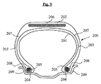
本発明およびその利点は、下記の詳細な記述および例示的な実施形態と、これらの実施例に関係し概略的に図示されている(縮尺は合っていない)図1〜9にも照らして容易に理解されよう。
The multicomponent composite reinforcements according to the invention are advantageously used for non-pneumatic tires or flexible wheels, owing to their low density and their improved properties during compression, bending and under lateral shear. It can also be used as a stiffening element, ie as structurally supported (without internal pressure). Such tires are well known to the person skilled in the art (
The invention and its advantages are facilitated in the light of the following detailed description and exemplary embodiments and also the figures (not to scale) schematically illustrated in connection with these examples. You will understand.
4.発明の詳細な説明
本出願では、他に特に指示しない限り、示される全てのパーセンテージ(%)は質量によるパーセンテージである。
「aからbの間(between a and b)」という表現により示される値の任意の範囲は、aを超えてb未満に及ぶ値の領域を表し(即ち、aおよびbを除外する限度)、それに対して「a〜(から)b(まで)(from a to b)」という表現によって示される値の任意の範囲は、aからbにまで至る値の領域を意味する(即ち、厳密な限度aおよびbを含む)。
したがって本発明は、多成分複合材タイプの補強材に関し、言い換えれば、少なくとも:
− Tg1で示されるそのガラス転移温度が150℃よりも高い、熱硬化性樹脂に埋め込まれたガラスフィラメントを含むGRCで作製された、1つまたは複数のモノフィラメント;
− 前記モノフィラメントを、各モノフィラメントを個別にまたはいくつかのモノフィラメントをまとめて覆う、熱可塑性材料の層であって、Tg2で示されるそのガラス転移温度が20℃よりも高い層
を含む、必須の特徴を有する車両用タイヤなどのゴム物品を補強するために特に使用することができる、複合材の複合材に関する。
4. Detailed Description of the Invention In the present application, unless stated otherwise, all percentages (%) indicated are percentages by weight.
Any range of values given by the expression "between a and b" represents a range of values beyond a and below b (ie the limit excluding a and b), On the other hand, any range of values indicated by the expression “a to b” means the range of values from a to b (ie the exact limit a) and b).
Accordingly, the present invention relates to reinforcements of the multicomponent composite type, in other words at least:
One or more monofilaments made of GRC comprising glass filaments embedded in a thermosetting resin whose glass transition temperature, indicated by Tg 1 , is higher than 150 ° C .;
-A layer of thermoplastic material which covers the monofilaments individually or collectively with several monofilaments, the layer having a glass transition temperature of more than 20 ° C., indicated by Tg 2 , essential Composite composites that can be used in particular to reinforce rubber articles such as vehicle tires having the features.
言い換えれば、本発明の多成分複合補強材は、単一またはいくつかのGRCモノフィラメントまたはスレッドを含み、各GRCスレッドまたはモノフィラメントは、熱可塑性材料の少なくとも1つの層によって覆われる(個々にまたはまとめて)。
熱可塑性材料のこのシースまたは層の存在によって、従来技術からのGRCモノフィラメントの場合に比べ、特に高温(典型的には150℃超)において著しく改善された、圧縮、曲げの最中、または横剪断下(モノフィラメントの軸に直交する)での耐久性というGRCモノフィラメントの性質が得られることが観察された。
In other words, the multi-component composite reinforcement of the invention comprises single or several GRC monofilaments or threads, each GRC thread or monofilament covered by at least one layer of thermoplastic material (individually or collectively) ).
The presence of this sheath or layer of thermoplastic material significantly improves compression, during bending or transverse shear, especially at high temperatures (typically above 150 ° C.), as compared to the case of GRC monofilaments from the prior art It was observed that the properties of the GRC monofilaments of durability down (perpendicular to the monofilament axis) were obtained.
本発明の多成分複合補強材の構造を、以下の詳細に記述する。
本発明の多成分複合補強材の直径DRは、好ましくは0.3から3.0mmの間であり、より好ましくは0.4から2.5mmの間であり、特に0.5から2.2mmの間である。
この定義は、本質的に円筒形状(円形断面を有する)の多成分複合補強材とその他の形状の多成分複合補強材、例えば長円形補強材(多かれ少なかれ平らな形状を有する)または長方形(正方形を含む)断面を有する補強材とを等しく包含する。非円形断面の場合、DRは、慣例的に、多成分複合補強材の厚さである。
20℃で測定される、多成分複合補強材のArで示される破断点伸びは、好ましくは3.0%以上であり、より好ましくは3.5%以上である。20℃で測定されるその初期引張り係数ER20は、好ましくは9GPa超であり、より好ましくは12GPa超である。
The structure of the multicomponent composite reinforcement of the present invention is described in detail below.
The diameter D R of the multi-component composite reinforcement of the present invention is preferably between 0.3 and 3.0 mm, more preferably between 0.4 to 2.5 mm, especially from 0.5 2. Between 2 mm.
This definition applies to multi-component composite reinforcements of essentially cylindrical shape (with a circular cross section) and multi-component composite reinforcements of other shapes, such as oval reinforcements (with more or less flat shapes) or rectangular (squares) And equally encompassing reinforcements having a cross section. For non-circular cross sections, D R is conventionally the thickness of a multicomponent composite reinforcement.
The elongation at break in Ar of the multi-component composite reinforcing material, which is measured at 20 ° C., is preferably 3.0% or more, more preferably 3.5% or more. Its initial tensile modulus E R20 measured at 20 ° C. is preferably more than 9 GPa, more preferably more than 12 GPa.
本発明のこの多成分複合補強材において、20℃で測定された前記または各GRCモノフィラメントの初期引張り係数(EM20)は、好ましくは30GPa超であり、より好ましくは33GPa超である。
上記引張り機械特性(Ar、ER20、およびEM20)は、製造時の状態の多成分複合補強材またはGRCモノフィラメントに関し、即ちサイズ決めされておらず、もしくはサイズ決めされており(即ち、使用の準備ができている)、または補強されたゴムで作製された半完成製品もしくは物品から抽出された状態のものに関し、標準ASTM D 638により「Instron」4466型引張り試験機(引張り試験機と共に供給されたBLUEHILL−2ソフトウェア)を使用して、公知の手法で測定される。測定前に、これらの多成分複合補強材またはこれらのGRCモノフィラメントを、従来の状態調節に供する(欧州規格DIN EN 20139により、標準大気中で少なくとも24時間貯蔵(温度20±2℃;相対湿度50±5%))。試験をしたサンプルを、0.5cN/texの標準プレテンションの下、公称速度100m/分で、400mmの初期長さにわたって引張り応力に供する。得られた全ての結果は、10個の測定値の平均値である。
In this multicomponent composite reinforcement according to the invention, the initial tensile modulus (E M20 ) of the or each GRC monofilament measured at 20 ° C. is preferably more than 30 GPa, more preferably more than 33 GPa.
The above tensile mechanical properties (Ar, E R20 and E M20 ) relate to the as-manufactured multi-component composite reinforcement or GRC monofilament, ie unsized or sized (ie used Prepared according to standard ASTM D 638, “Instron” model 4466 tensile tester (supplied with a tensile tester), as prepared or prepared from semifinished products or articles made of reinforced rubber Measured in a known manner, using the Prior to measurement, these multicomponent composite reinforcements or their GRC monofilaments are subjected to conventional conditioning (storage according to European Standard DIN EN 20139 in a standard atmosphere for at least 24 hours (
本発明の多成分複合補強材を構成する個々のGRCモノフィラメントは、任意の公知の形をとってもよい。例えば、直径が大きい(好ましくは、100μm超)、即ち本質的に円形断面の円筒状モノフィラメント、そうでない場合には本質的に長方形(正方形を含む)の断面の個別のストリップのモノフィラメントであってもよく;熱可塑性材料の層は、前記モノフィラメントまたは各モノフィラメントを個々に覆うことが理解される。
典型的には、ガラスフィラメントは、単一のマルチフィラメント繊維またはいくつかのマルチフィラメント繊維(いくつかある場合は、好ましくは本質的に一方向である)の形で存在し、そのそれぞれは、数十、数百、またはさらに数千の単体のガラスフィラメントを含むことができるものである。これらの非常に微細な単体フィラメントは一般に、好ましくは、5〜30μm程度の、より好ましくは10〜20μmの平均直径を有する。
The individual GRC monofilaments that make up the multicomponent composite reinforcements of the present invention may take any known form. For example, cylindrical monofilaments of large diameter (preferably greater than 100 μm), ie of essentially circular cross section, otherwise monofilaments of individual strips of essentially rectangular (including square) cross section Well; it is understood that the layer of thermoplastic material covers the or each monofilament individually.
Typically, the glass filaments are present in the form of a single multifilament fiber or several multifilament fibers (in some cases, preferably essentially unidirectional), each of which Ten, hundreds, or even thousands of single glass filaments can be included. These very fine elementary filaments generally have an average diameter preferably of the order of 5 to 30 μm, more preferably 10 to 20 μm.
本明細書において「樹脂」という用語は、非修飾形態の樹脂、およびこの樹脂をベースとして少なくとも1種の添加剤(即ち、1種または複数の添加剤)を含む任意の組成物を意味するものとする。「熱硬化性樹脂」または「架橋樹脂」という用語は、当然ながら、樹脂が硬化(光硬化および/または熱硬化)されたこと、言い換えれば、「熱硬化性」ポリマー特異的な状態にある(「熱可塑性」ポリマーとは対照的に)三次元結合の網状構造の形をとることを意味するものとする。
樹脂の、Tg1で示されるガラス転移温度は、好ましくは160℃よりも高く、より好ましくは170℃よりも高く、特に180℃よりも高い。
As used herein, the term "resin" is intended to mean the resin in unmodified form and any composition comprising at least one additive (ie one or more additives) based on this resin. I assume. The terms "thermosetting resin" or "crosslinked resin" are, of course, that the resin has been cured (photocured and / or heat cured), in other words, in a "thermosetting" polymer specific state ( In the context of "thermoplastic" polymers) is meant to be in the form of a three-dimensional bonded network.
The glass transition temperature of the resin, indicated by Tg 1 , is preferably above 160 ° C., more preferably above 170 ° C., in particular above 180 ° C.
特に好ましい一実施形態によれば、DMTA法により150℃で測定された、各GRCモノフィラメントの複素弾性係数(E’150)の実数部は、25GPaよりも大きく、好ましくは30GPaよりも大きい。
特に好ましい別の実施形態によれば、本発明の多成分複合補強材の熱的性質と機械的性質との最適な折衷案の場合、E’(Tg1-25)/E’20比は0.85よりも大きく、好ましくは0.90よりも大きく、E’20およびE’(Tg1-25)は、それぞれ20℃でおよび(Tg1−25)と等しい℃を単位として表される温度でDMTAにより測定された、各モノフィラメントの複素弾性係数の実数部である。
E’の測定は、DMTA(「動的機械熱分析:Dynamic Mechanical Thermal Analysis」)により、公知の手法で実施され、曲げ、引張り、または捩じり試験を制御する「Dynatest 6.83/2010」ソフトウェアを使用したACOEM(フランス)製「DMA+ 450」粘度分析器を用いる。
このデバイスによれば、3点曲げ試験は、公知の手法において、円形断面のモノフィラメントに関する初期幾何形状データの入力が可能にならないので、長方形(または正方形)断面の幾何形状のみを入力してもよい。したがって、直径DMのGRCモノフィラメントに関する弾性係数E’の精密な測定値を得るために、慣例では、試験がなされた試験片と同じ剛性Rで作用できるように、同じ表面慣性モーメントを有する辺の長さ「a」の正方形断面をソフトウェアに導入する。
According to a particularly preferred embodiment, the real part of the complex elastic modulus (E ' 150 ) of each GRC monofilament, measured at 150 ° C. by the DMTA method, is greater than 25 GPa, preferably greater than 30 GPa.
According to a particularly preferred alternative embodiment, in the case of an optimal compromise between the thermal and mechanical properties of the multicomponent composite reinforcement according to the invention, the ratio E ′ (Tg1-25) / E ′ 20 is 0. greater than 85, DMTA preferably greater than 0.90, the temperature represented E '20 and E' (Tg1-25) are respectively 20 ° C. and equal ° C. to (Tg 1 -25) as a unit , The real part of the complex elastic modulus of each monofilament.
The measurement of E 'is performed by DMTA ("Dynamic Mechanical Thermal Analysis") by a known method and controls bending, tension or torsion test "Dynatest 6.83 / 2010" Use ACOEM (France) "DMA + 450" viscosity analyzer using software.
According to this device, the 3-point bending test may only input the geometry of rectangular (or square) cross-sections, as it does not allow the entry of initial geometry data for circular mono-filaments in a known manner. . Thus, in order to obtain a precise measurement of the modulus of elasticity E 'for a GRC monofilament of diameter D M , it is customary to act on the side with the same surface moment of inertia so that it can operate with the same stiffness R as the tested specimen. Introduce a square cross section of length "a" into the software.
下記の周知の関係を、適用しなければならない(Eは材料の弾性係数であり、Isは問題となっている目的の表面慣性モーメントであり、*は乗算記号である):
R=E複合材 *I円形断面=E複合材 *I正方形断面
式中:I円形断面=π*DM 4/64であり、I正方形断面=a4/12である。
直径DMのGRCモノフィラメントの(円形)断面の場合と同じ表面慣性を持つ均等な正方形の辺の長さ「a」の値は、方程式:
a=DM *(π/6)0.25
により、そこから容易に推論される。
The following known relationships must be applied (E is the modulus of elasticity of the material, I s is the surface inertia moment of the object in question, * is the multiplication symbol):
R = E composite * I circular cross section = E composite * I square cross section
Wherein: an I-circular cross-section = π * D M 4/64 , an I square section = a 4/12.
The value of the side length "a" of an even square with the same surface inertia as in the case of the (circular) cross section of a GRC monofilament of diameter D M is the equation:
a = D M * (π / 6) 0.25
It is easily deduced from there.
試験をしたサンプルの断面が円形(または長方形)ではない場合、その特定の形状とは無関係に、試験をしたサンプルの断面に関して表面慣性モーメントISの従来の決定と同じ計算方法が適用されることになる。
ほぼ円形の断面であり直径がDMである、試験がなされる試験片は、35mmの長さを有する。2つの支持体上に、互いに24mmの間隔を空けて水平に配置構成される。繰り返される曲げ応力は、10Hzの周波数で0.1mmに等しい大きさの垂直変位の形をとって(したがって、非対称変形であり、試験片の内側には延伸中ではなく圧縮中にのみ応力がかかる)、2つの支持体の中間で試験片の中心に対して直角に加えられる。
If the cross section of the tested sample is not circular (or rectangular), the same calculation method as the conventional determination of the surface inertia moment I S is applied to the cross section of the tested sample, regardless of its specific shape become.
The specimens to be tested, of approximately circular cross section and diameter D M , have a length of 35 mm. The two supports are arranged horizontally at a distance of 24 mm from each other. The repeated bending stress takes the form of a vertical displacement equal to 0.1 mm at a frequency of 10 Hz (thus an asymmetric deformation and the inside of the specimen is only stressed during compression, not during stretching) ), Which is added at a right angle to the center of the test strip, halfway between the two supports.
次いで下記のプログラムを適用する:この動的応力の下、試験片を25℃から260℃に、2℃/分の勾配で徐々に加熱する。試験の終わりに、弾性係数E’、粘性係数E”、および損失角(δ)の測定値を、温度の関数として得る(E’は複素弾性係数の実数部であり、E”は複素弾性係数の虚数部である)。ガラス転移温度はDMTAにより測定されてもよいことがここでは単に想起され;これはtan(δ)の最大値(ピーク)に対応する。 The following program is then applied: Under this dynamic stress, the specimens are gradually heated from 25 ° C. to 260 ° C., with a gradient of 2 ° C./min. At the end of the test, measurements of elastic modulus E ', viscosity coefficient E "and loss angle (δ) are obtained as a function of temperature (E' is the real part of the complex elastic modulus and E" is the complex elastic modulus Is the imaginary part of It is merely recalled here that the glass transition temperature may be measured by DMTA; this corresponds to the maximum value (peak) of tan (δ).
好ましい実施形態によれば、各GRCモノフィラメントの曲げの最中の圧縮弾性変形は、3.0%よりも大きく、より好ましくは3.5%よりも大きい。別の好ましい実施形態によれば、曲げの最中の圧縮破断応力は、1000MPaよりも大きく、より好ましくは1200MPaよりも大きい。
上記圧縮曲げ特性は、ループ試験(D. Sinclair, J. App. Phys. 21, 380, 1950)と呼ばれる方法によって、前述の出願EP 1 167 080に記載されるようにGRCモノフィラメントで測定される。本発明の場合、ループは生成されかつ徐々にその破断点に至る。断面の大きなサイズに起因して容易に観察可能な破断の性質は、それが破断するまで曲げている最中に応力が加えられる本発明のGRCモノフィラメントにおいて、単に観察によって特定することができるような材料が延伸している側での破断を実現するのを即座に可能にする。この場合、ループの寸法が大きいとすれば、ループに内接する円の半径を読み取ることがいつでも可能になる。破断点直前の内接する円の半径は、Rcにより示される臨界曲率半径に該当する。
次いで下記の式は、計算によって、Ecで示される臨界弾性変形を決定するのを可能にする(式中、rはモノフィラメントの半径に該当し、即ちDM/2である):
Ec=r/(Rc+r)
σcで示される曲げの最中の圧縮破断応力は、下記の式(式中、Eは初期引張り係数である)を使用する計算によって得られる:
σc=Ec*E
According to a preferred embodiment, the compressive elastic deformation during bending of each GRC monofilament is more than 3.0%, more preferably more than 3.5%. According to another preferred embodiment, the compressive breaking stress during bending is greater than 1000 MPa, more preferably greater than 1200 MPa.
Said compressive bending properties are measured on GRC monofilaments as described in the
The following equation then makes it possible to determine by calculation the critical elastic deformation noted E c, where r corresponds to the radius of the monofilament, ie D M / 2:
Ec = r / (Rc + r)
The compressive fracture stress during bending, denoted σ c , is obtained by calculation using the following equation: where E is the initial tensile modulus:
σ c = Ec * E
GRCモノフィラメントの場合、ループは延伸部分で破断するので、そこから、曲げの最中の圧縮破断応力が引張り破断応力よりも大きいと結論付けられる。
3点法(ASTM D 790)と呼ばれる方法による長方形のバーの撓み破断を実施してもよい。この方法も、破断の性質が実際に延伸におけるものであることを視覚的に検証するのを可能にする。
好ましい実施形態によれば、純粋な圧縮における破断応力は、700MPaよりも大きく、より好ましくは900MPaよりも大きく、特に1100MPaよりも大きい。圧縮下でのGRCモノフィラメントの座屈を回避するために、この大きさを、刊行物「Critical compressive stress for continuous fiber unidirectional composites」、Thompson et al.、Journal of Composite Materials, 46(26), 3231-3245に記載される方法により測定する。
In the case of GRC monofilaments, the loop breaks at the stretch, so it can be concluded that the compressive breaking stress during bending is greater than the tensile breaking stress.
Flexural fracture of rectangular bars may be performed by a method called the three point method (ASTM D 790). This method also makes it possible to visually verify that the nature of the fracture is indeed in the stretch.
According to a preferred embodiment, the breaking stress in pure compression is more than 700 MPa, more preferably more than 900 MPa, in particular more than 1100 MPa. In order to avoid the buckling of GRC monofilaments under compression, this size is disclosed in the publication "Critical compressive stress for continuous fiber unidirectional composites", Thompson et al., Journal of Composite Materials, 46 (26), 3231-. It is measured by the method described in 3245.
好ましくは、各GRCモノフィラメントにおいて、ガラスフィラメントの整合の程度は、フィラメントの85%超(本数%)が、モノフィラメントの軸に対して2.0度未満、より好ましくは1.5度未満傾斜しているようなものであり、この傾斜(または不整合)は、Thompson et al.による上記刊行物に記載されるように測定されるものである。
好ましくは、前記または各GRCモノフィラメント中のガラス繊維の質量含量は、60から80%の間、好ましくは65から75%の間である。
Preferably, in each GRC monofilament, the degree of alignment of the glass filaments is such that more than 85% (several percent) of the filaments are inclined less than 2.0 degrees, more preferably less than 1.5 degrees with respect to the axis of the monofilaments The slope (or misalignment) is measured as described in the above-mentioned publication by Thompson et al.
Preferably, the mass content of glass fibers in the or each GRC monofilament is between 60 and 80%, preferably between 65 and 75%.
この質量含量は、初期ガラス繊維のカウント数とGRCモノフィラメントのカウント数との比から計算される。カウント数(または線形密度)は、それぞれが50mの長さに相当する少なくとも3つのサンプルに関して、この長さを計量することによって決定され;そのカウント数は、tex(生成物1000mの、グラムを単位とした質量−心覚えとして、0.111texは1デニールに等しい)で与えられる。
好ましくは、前記または各GRCモノフィラメントの密度は、1.8から2.1の間である。「PG503 DeltaRange」型のMettler Toledo製の専用天秤を用いて測定され(23℃で);数cmのサンプルを空気中で連続的に計量し、エタノールに浸漬し、次いで装置のソフトウェアが、3回の測定に関する平均密度を決定する。
前記または各モノフィラメントの直径DMは、好ましくは0.2から2.0mmの間であり、より好ましくは0.3から1.5mmの間であり、特に0.4から1.2mmの間である。
This mass content is calculated from the ratio of the initial glass fiber count to the GRC monofilament count. The number of counts (or linear density) is determined by weighing this length for at least three samples, each corresponding to a length of 50 m; the number of counts is tex (grams of product 1000 m, units And mass-as a reminder, 0.111 tex is given by 1 denier).
Preferably, the density of the or each GRC monofilament is between 1.8 and 2.1. Measured (at 23 ° C.) using a dedicated balance from Mettler Toledo of the “PG 503 DeltaRange” type; a few cm of the sample are weighed continuously in air, soaked in ethanol, then the software of the device is 3 times Determine the average density for the measurement of
The or each monofilament diameter D M is preferably between 0.2 and 2.0 mm, more preferably between 0.3 and 1.5 mm, in particular between 0.4 and 1.2 mm. is there.
この定義は、本質的に円筒形状(円形断面を有する)のモノフィラメント、およびその他の形状のモノフィラメント、例えば長円形のモノフィラメント(多かれ少なかれ楕円形の、平らな形状を有する)、または長方形の断面のモノフィラメントを等しく包含する。非円形、例えば楕円形または長方形の断面の場合、他の内容が特に示されていない限り、慣例的にDMは、クリアランス径として公知の直径であり、即ち、モノフィラメントを取り囲む回転の仮想的な円筒の直径であり、言い換えれば、その断面に外接する円の直径である。
使用される初期樹脂は、定義によれば、任意の方法によって、特にUV(またはUV−可視)放射線によって、好ましくは少なくとも300nmから450nmに及ぶスペクトルで放出された放射線によって硬化された、架橋することが可能な架橋性(即ち、硬化性)樹脂である。
架橋性樹脂として、好ましくはポリエステルまたはビニルエステル樹脂、好ましくはビニルエステル樹脂製が使用される。「ポリエステル」樹脂という用語は、公知の方法で、不飽和ポリエステル型の樹脂を意味するものとする。ビニルエステル樹脂に関し、それらは複合材料の分野で周知である。
This definition applies to monofilaments of essentially cylindrical shape (with circular cross section), and monofilaments of other shapes, such as oval monofilaments (with more or less elliptical, flat shapes), or monofilaments of rectangular cross section Is equally included. In the case of non-circular, eg oval or rectangular cross-sections, customarily, D M is a diameter known as clearance diameter, ie, the imaginary rotation of rotation surrounding the monofilament, unless otherwise indicated otherwise. It is the diameter of a cylinder, in other words the diameter of a circle circumscribing its cross section.
The initial resin used is, by definition, crosslinked, cured by any method, in particular by UV (or UV-visible) radiation, preferably by radiation emitted in a spectrum ranging from at least 300 nm to 450 nm Crosslinkable (i.e., curable) resin.
As a crosslinkable resin, preferably polyester or vinyl ester resin, preferably vinyl ester resin is used. The term "polyester" resin is taken to mean, in a known manner, a resin of unsaturated polyester type. With respect to vinyl ester resins, they are well known in the field of composites.
この定義に限定するものではないが、ビニルエステル樹脂は、好ましくはエポキシビニルエステル型のものである。より好ましくは、少なくとも部分的にノボラック(フェノプラストとしても公知)および/またはビスフェノール(即ち、このタイプの構造にグラフト化される)をベースにした、特にエポキシド型のビニルエステル樹脂製、または好ましくは、ノボラック、ビスフェノール、もしくはノボラックおよびビスフェノールをベースにしたビニルエステルが使用される。 Without limitation to this definition, the vinyl ester resin is preferably of the epoxy vinyl ester type. More preferably, it is made of a vinyl ester resin, in particular of epoxide type, based at least in part on novolac (also known as phenoplast) and / or bisphenol (ie grafted onto this type of structure), or preferably Novolak, bisphenol, or vinyl esters based on novolak and bisphenol are used.
ノボラック(下記の式I中、括弧内の部分)をベースにしたエポキシビニルエステル樹脂は、例えば、公知の方法で、下記の式(I)に該当する: Epoxy vinyl ester resins based on novolaks (in formula I below, the part in brackets) correspond, for example, to the following formula (I) in a known manner:

ビスフェノールA(下記の式(II)中、括弧内の部分)をベースにしたエポキシビニルエステル樹脂は、例えば、この式に該当する(「A」は、生成物がアセトンを使用して製造されたことを示唆するものとして働く): Epoxy vinyl ester resins based on bisphenol A (in formula (II) below, part in parentheses) correspond, for example, to this formula ("A" was produced using acetone as the product) Act as a suggestion):
ノボラックおよびビスフェノール型のエポキシビニルエステル樹脂は、優れた結果を実証した。そのような樹脂の例として、上述の出願EP−A−1 074 369およびEP−A−1 174 250に記載されるDSM製のビニルエステル樹脂製「Atlac 590」および「E−Nova FW 2045」(約40%のスチレンで希釈したもの)を特に挙げてもよい。エポキシビニルエステル樹脂は、例えばAOC(USA−「Vipel」樹脂)など、その他の製造業者から入手可能である。
好ましくは、本発明の多成分複合補強材において、20℃で測定された熱硬化性樹脂の初期引張り係数は、3.0GPaよりも大きく、より好ましくは3.5GPaよりも大きい。
本発明の多成分複合補強材を構成する個々のGRCモノフィラメントは周知であり、それらは、少なくとも下記のステップ:
− ガラス繊維(フィラメント)の直線的配置構成を生成し、この配置構成を供給方向に搬送するステップ;
− 真空チャンバ内で、真空の作用により繊維の配置構成を脱気するステップ;
− 真空チャンバの出口で、脱気後に、真空下で含浸チャンバ内を通過させて、ガラスフィラメントおよび樹脂を含有するプリプレグを得るために、液体状態の熱硬化樹脂または樹脂組成物を繊維の前記配置構成に含浸させるようにするステップ;
− 前記プリプレグを、所定の面積および形状の断面を有するサイジングダイに通して、モノフィラメントの形状(例えば、丸い断面を有するモノフィラメントまたは長方形の断面を有するストリップ)を与えるステップ;
− ダイの下流で、UV照射チャンバ内で、UV線の作用の下で樹脂を重合させるステップ;
− 次いでこのように得られたモノフィラメントを、中間貯蔵のために巻き取るステップ
を含む公知のプロセスにより、好ましい手法で調製されてもよい。
Novolak and bisphenol type epoxy vinyl ester resins have demonstrated excellent results. As an example of such a resin, "Atlac 590" and "E-Nova FW 2045" made of vinyl ester resin manufactured by DSM described in the above-mentioned applications EP-A-1 074 369 and EP-A-1 174 250 Mention may be made in particular of those diluted with about 40% of styrene). Epoxy vinyl ester resins are available from other manufacturers, such as, for example, AOC (USA- "Vipel" resin).
Preferably, in the multicomponent composite reinforcement of the present invention, the initial tensile modulus of the thermosetting resin measured at 20 ° C. is greater than 3.0 GPa, more preferably greater than 3.5 GPa.
The individual GRC monofilaments that make up the multicomponent composite reinforcements of the invention are well known and they comprise at least the following steps:
-Producing a linear arrangement of glass fibers (filaments) and conveying this arrangement in the feed direction;
-Degassing the arrangement of fibers in the vacuum chamber by the action of vacuum;
Said placement of the fibers in the liquid state thermoset resin or resin composition in order to obtain a prepreg containing glass filaments and resin after degassing at the outlet of the vacuum chamber and passing under vacuum through the impregnation chamber Allowing the composition to be impregnated;
Passing the prepreg through a sizing die having a cross section of a predetermined area and shape to provide a monofilament shape (eg, a monofilament having a round cross section or a strip having a rectangular cross section);
-Polymerizing the resin under the action of UV radiation in a UV irradiation chamber downstream of the die;
The monofilaments thus obtained may then be prepared in a preferred manner by known processes comprising the step of winding up for intermediate storage.
上記ステップの全て(配置構成し、脱気し、含浸し、サイズ決めし、重合し、最終的に巻き取るステップ)は、使用される材料(マルチフィラメント繊維および樹脂組成物)と同様に、当業者に周知のステップであり;それらは例えば、出願EP−A−1 074 369およびEP−A−1 174 250に記載されている。
特に、後半の含浸の有効性を増大させるために、とりわけ完成した複合材モノフィラメント内に気泡が存在しないことを保証するために、繊維の任意の含浸前に、真空の作用によって繊維の配置構成を脱気するステップが好ましくは実施されることが、特に想起されることになる。
All of the above steps (arrangement, degassing, impregnating, sizing, polymerizing and finally winding up), as well as the materials used (multifilament fibers and resin composition) These are steps well known to the trade; they are described, for example, in the applications EP-A-1 074 369 and EP-A-1 174 250.
In particular, in order to increase the effectiveness of the latter impregnation, in particular to ensure that no air bubbles are present in the finished composite monofilament, the arrangement of the fibers by the action of vacuum before any impregnation of the fibers. It will be particularly recalled that the degassing step is preferably carried out.
真空チャンバ内を通過させた後、ガラスフィラメントは、含浸樹脂で完全に満たされた、したがって空気がない含浸チャンバに進入し:このようにして、この含浸ステップを「真空下での含浸」と記述することができるようになった。
含浸樹脂(樹脂組成物)は、好ましくは、300nm超、好ましくは300から450nmの間のUV線に対して感受性(反応性)のある光開始剤を含む。この光開始剤は、好ましくは0.5%〜3%、より好ましくは1%〜2.5%の量で使用される。樹脂は、架橋剤を、例えば5%から15%(含浸組成物に対する質量%)の間の量で含んでいてもよい。
After passing through the vacuum chamber, the glass filaments enter the impregnation chamber completely filled with the impregnating resin and thus without air: thus, this impregnation step is described as "impregnation under vacuum" It became possible to do.
The impregnated resin (resin composition) preferably comprises a photoinitiator sensitive (reactive) to UV radiation above 300 nm, preferably between 300 and 450 nm. The photoinitiator is preferably used in an amount of 0.5% to 3%, more preferably 1% to 2.5%. The resin may comprise a crosslinking agent, for example in an amount of between 5% and 15% (% by weight with respect to the impregnating composition).
好ましくは、この光開始剤は、ホスフィン化合物の系列からのものであり、より好ましくは、例えばビス(2,4,6−トリメチルベンゾイル)フェニルホスフィンオキシド(BASF製「Irgacure 819」)などのビス(アシル)ホスフィンオキシド、またはモノ(アシル)ホスフィンオキシド(例えば、Lamberti製「Esacure TPO」)であって、その他の光開始剤、例えばα−ヒドロキシケトン型の光開始剤、例えばジメチルヒドロキシアセトフェノン(例えば、Lamberti製「Esacure KL200」)もしくは1−ヒドロキシシクロヘキシルフェニルケトン(例えば、Lamberti製「Esacure KS300」)、2,4,6−トリメチルベンゾフェノン(例えば、Lamberti製「Esacure TZT」)などのベンゾフェノンおよび/または例えばイソプロピルチオキサントン(例えば、Lamberti製「Esacure ITX」)などのチオキサントン誘導体との混合物中で使用することができるホスフィン化合物などである。 Preferably, the photoinitiator is from the series of phosphine compounds, more preferably bis (2) (such as bis (2,4,6-trimethylbenzoyl) phenyl phosphine oxide ("Irgacure 819" from BASF) Acyl) phosphine oxide, or mono (acyl) phosphine oxide (for example, "Esacure TPO" from Lamberti), which is another photoinitiator, for example, a photoinitiator of α-hydroxy ketone type, for example dimethylhydroxyacetophenone (for example, Lamberti “Esacure KL200”) or 1-hydroxycyclohexyl phenyl ketone (eg Lamberti “Esacure KS300”), 2,4,6-trimethylbenzophenone (eg Lambert) such as phosphine compounds which can be used in mixtures with benzophenones such as "Esacure TZT" from i) and / or thioxanthone derivatives such as, for example, isopropyl thioxanthone (for example, "Esacure ITX" from Lamberti).
「サイジング」ダイは、決定された寸法の断面、一般にかつ好ましくは円形または長方形の断面を有することによって、ガラス繊維に対する樹脂の割合を調節するのを可能にすると同時に、モノフィラメントに必要な形状および太さをプリプレグに課すのを可能にする。
次いで重合またはUV照射チャンバは、UV線の作用の下で、樹脂を重合し架橋する機能を有する。このチャンバは、例えば200〜600nmの波長を持つUVランプからそれぞれ構成された1つまたは好ましくはいくつかのUV照射器を含む。
The "sizing" die allows to adjust the ratio of resin to glass fiber by having a cross-section of determined dimensions, generally and preferably a circular or rectangular cross-section, while at the same time the required shape and size of the monofilament It makes it possible to impose on the prepreg.
The polymerization or UV irradiation chamber then has the function of polymerizing and crosslinking the resin under the action of UV radiation. This chamber contains one or preferably several UV irradiators, each of which is composed, for example, of a UV lamp with a wavelength of 200 to 600 nm.
次いで、ここで樹脂が固体状態にある、UV照射チャンバを通してこのように形成された最終GRCモノフィラメントを、例えば巻取りリールで回収し、そのリール表面に、非常に大きい長さにわたって巻き取ってもよい。
サイジングダイと最終受容支持体の間では、中間レベルで、好ましくは0.2から2.0cN/texの間、より好ましくは0.3から1.5cN/texの間で、ガラス繊維が供される張力を保つことが好ましく;これを制御するために、例えばこれらの張力を、当業者に周知の適切な張力計を用いて照射チャンバの出口で直接測定することが可能になる。
The final GRC monofilament so formed may then be collected, for example on a take-up reel, through a UV irradiation chamber, where the resin is now in solid state, and wound onto the reel surface over a very large length .
Glass fibers are provided at an intermediate level, preferably between 0.2 and 2.0 cN / tex, more preferably between 0.3 and 1.5 cN / tex, between the sizing die and the final receiving support. To control this, it is possible, for example, to measure these tensions directly at the outlet of the irradiation chamber using a suitable tensiometer well known to the person skilled in the art.
最後に、図1に示される、完成した製造済み複合材ブロックが、その断面に対して非常に大きい長さを有する直径DMの連続GRCモノフィラメント(10)の形で得られ、その単体ガラス繊維(101)は、硬化された樹脂(102)の体積全体にわたって均質に分布されている。
有利には、熱可塑性材料(12)のシースを堆積する前に、上述の熱硬化性樹脂(102)と熱可塑性シース(12)との間で、後で行われる接着を改善するために、GRCモノフィラメント(10)を接着処理に供してもよい。適切な化学処理は、例えば、エポキシ樹脂および/またはイソシアネート化合物をベースにした水性浴内に事前に通し、その後、水をなくし接着層を重合させることを目的として少なくとも1回の熱処理を行うことからなるものとすることができる。そのような接着処理は、当業者に周知である。
Finally, a finished manufactured composite block, shown in FIG. 1, is obtained in the form of continuous GRC monofilaments (10) of diameter D M having a very large length with respect to its cross section, its single glass fiber (101) is homogeneously distributed throughout the volume of the cured resin (102).
Advantageously, before the deposition of the sheath of thermoplastic material (12), in order to improve the subsequent adhesion between the thermosetting resin (102) described above and the thermoplastic sheath (12), GRC monofilaments (10) may be subjected to adhesion processing. A suitable chemical treatment is, for example, pre-passing in an aqueous bath based on epoxy resin and / or isocyanate compound and then performing at least one heat treatment for the purpose of eliminating water and polymerizing the adhesive layer. It can be Such adhesion processes are well known to those skilled in the art.
GRCモノフィラメント(10)が完成したら、後者をシースで覆い、公知の手法で、例えばモノフィラメントを、または適切ないくつかのモノフィラメントが平行に位置決めされている場合にも、溶融状態で熱可塑性材料を送出する適切な押出しヘッド内に通すことによって、熱可塑性材料(12)の層で覆う。
熱可塑性材料でシース形成しまたは覆うステップは、当業者に公知の手法で実施する。例えばその手法は、単に、それまたは各GRCモノフィラメントを適切な直径の1つまたは複数のダイに通し、適切な温度に加熱された押出しヘッドに通し、またはそうでない場合には適切な有機溶媒(または溶媒の混合物)中に事前に溶解させた熱可塑性材料が入っているコーティング浴に通すことからなる。
次いで各押出しヘッドから出たら、このようにシース形成されたフィラメントを、例えば空気もしくは別の低温気体で、または水浴に通すことによって、熱可塑性材料の層が凝固するように十分に冷却し、その後、乾燥段階に供する。
Once the GRC monofilament (10) is complete, the latter is sheathed and the thermoplastic material is delivered in the molten state in a known manner, for example, even if the monofilament or a suitable number of monofilaments are positioned in parallel. Cover with a layer of thermoplastic material (12) by passing through a suitable extrusion head.
The step of sheathing or covering the thermoplastic material is carried out in a manner known to the person skilled in the art. For example, the procedure simply passes the or each GRC monofilament through one or more dies of appropriate diameter, through an extrusion head heated to an appropriate temperature, or otherwise an appropriate organic solvent (or Passing through a coating bath containing the thermoplastic material previously dissolved in the mixture of solvents).
Then as it exits each extrusion head, it is cooled sufficiently to solidify the layer of thermoplastic material, for example by passing it through a sheathed filament, for example with air or another cold gas, or through a water bath, and then , Subject to the drying stage.
例として、全直径が約1.4mmの多成分複合補強材を得るために、約1mmの直径を有するGRCモノフィラメントを、最小厚さEmが約0.2mmに等しいPET層で覆うステップを、2つのダイを含む押出し/シース形成ラインで実施するが、第1のダイ(対向ダイまたは上流ダイ)は約1.05mmに等しい直径を有し、第2のダイ(または下流ダイ)は約1.45mmに等しい直径を有し、両方のダイは約290℃になる押出しヘッドに位置決めされている。したがって、押出し器内で280℃の温度で融解するポリエステルは、シース形成ヘッドを介してGRCモノフィラメントを覆い、このときの、典型的には数十cm3/分である押出しポンプ流量に関してスレッド走行速度は典型的には数十m/分に等しい。この第1のシース形成操作から出たら、その非晶質状態にあるポリエステルを凝固し硬化するために、スレッドを、冷水で満たされた冷却タンクに浸漬し、次いで例えばインラインで空気ノズルによって、または巻取りリールに通して炉内に入れることによって、乾燥してもよい。
前記または各GRCモノフィラメント(10)を覆う層またはシースは、そのガラス転移温度(Tg2)が20℃よりも高い、好ましくは50℃よりも高い、より好ましくは70℃よりも高い熱可塑性材料(12)からなる。さらに、この熱可塑性材料(12)の融解温度(Tmで示される)は、好ましくは150℃より高く、より好ましくは200℃よりも高い。
As an example, for full diameter to obtain a multi-component composite stiffener of about 1.4 mm, the step of the GRC monofilament having a diameter of about 1 mm, covered with a minimum thickness E m is PET layer equal to about 0.2 mm, Although implemented in an extrusion / sheath forming line comprising two dies, the first die (opposing die or upstream die) has a diameter equal to about 1.05 mm and the second die (or downstream die) is about 1 With a diameter equal to .45 mm, both dies are positioned on the extrusion head which will reach about 290.degree. Thus, the polyester melting at a temperature of 280 ° C. in the extruder covers the GRC monofilament through the sheathing head and at this time, the thread travel speed with respect to the extrusion pump flow rate, which is typically a few tens of cm 3 / min. Is typically equal to several tens of meters per minute. Upon exiting this first sheathing operation, the thread is dipped into a chilled tank filled with cold water to solidify and cure the polyester in its amorphous state, and then, for example, by an air nozzle in-line, or It may be dried by passing it through a take-up reel into the furnace.
The layer or sheath covering the or each GRC monofilament (10) is a thermoplastic material having a glass transition temperature (Tg 2 ) of more than 20 ° C., preferably more than 50 ° C., more preferably more than 70 ° C. 12). Furthermore, the melting temperature (denoted by Tm) of this thermoplastic material (12) is preferably above 150 ° C., more preferably above 200 ° C.
好ましくは、前記または各モノフィラメントを覆う熱可塑性材料の層の最小厚さ(Emで示される)は、0.05から0.5mmの間、より好ましくは0.1から0.4mmの間、特に0.1から0.3mmの間である。
好ましくは、この熱可塑性材料(12)の初期引張り係数は、500から2500MPaの間、好ましくは500から1500MPaの間であり;その弾性伸びは、好ましくは5%超であり、より好ましくは8%超であり、特に10%超であり;その破断点伸びは、好ましくは10%超であり、より好ましくは15%超であり、特に20%超である。
典型的には、熱可塑性材料は、ポリマーまたはポリマー組成物(少なくとも1種のポリマーおよび少なくとも1種の添加剤をベースとした組成物)である。
Preferably, the minimum thickness of the layer of thermoplastic material covering the or each monofilament (indicated by E m) is between 0.05 and 0.5 mm, more preferably between 0.4mm 0.1, In particular between 0.1 and 0.3 mm.
Preferably, the initial tensile modulus of this thermoplastic material (12) is between 500 and 2500 MPa, preferably between 500 and 1500 MPa; its elastic elongation is preferably more than 5%, more preferably 8% The elongation at break is preferably more than 10%, more preferably more than 15%, in particular more than 20%.
Typically, the thermoplastic material is a polymer or polymer composition (composition based on at least one polymer and at least one additive).
この熱可塑性ポリマーは、好ましくは、ポリアミド、ポリエステル、およびポリイミドと、そのようなポリマーの混合物とからなる群から選択され、より特別には、脂肪族ポリアミド、ポリエステル、およびそのようなポリマーの混合物からなる群から選択される。特に、脂肪族ポリアミドの中でも、ポリアミドPA−4,6、PA−6、PA−6,6、PA−11、またはPA−12を挙げてもよい。熱可塑性ポリマーは、好ましくはポリエステルであり;ポリエステルの中でも、例えば、PET(ポリエチレンテレフタレート)、PEN(ポリエチレンナフタレート)、PBT(ポリブチレンテレフタレート)、PBN(ポリブチレンナフタレート)、PPT(ポリプロピレンテレフタレート)、およびPPN(ポリプロピレンナフタレート)を挙げてもよい。 The thermoplastic polymer is preferably selected from the group consisting of polyamides, polyesters and polyimides and mixtures of such polymers, and more particularly from aliphatic polyamides, polyesters and mixtures of such polymers Are selected from the group consisting of In particular, among aliphatic polyamides, polyamides PA-4,6, PA-6, PA-6,6, PA-11 or PA-12 may be mentioned. The thermoplastic polymer is preferably a polyester; among polyesters, for example, PET (polyethylene terephthalate), PEN (polyethylene naphthalate), PBT (polybutylene terephthalate), PBN (polybutylene naphthalate), PPT (polypropylene terephthalate) And PPN (polypropylene naphthalate) may be mentioned.
染料、充填剤、可塑剤、抗酸化剤、またはその他の安定化剤などの様々な添加剤を、ポリマー組成物を形成するために上記ポリマーまたはポリマーの混合物に添加してもよい。ジエンゴムマトリックスへの接着を促進させることが可能な相溶性成分、好ましくは熱可塑性樹脂そのもの、例えば出願WO 2013/117474およびWO 2013/117475に記載されている、特にエポキシ化された、例えば飽和型のTPS(熱可塑性スチレン)エラストマーを、上記熱可塑性材料に有利には添加することができる。
Tg1およびTg2は、DSC(示差走査熱量測定:Differential Scanning Calorimetry)による公知の手法で、例えば2回目のパスで測定され、また他に本出願で指示されない限り、標準ASTM D3418(1999)により測定される(Mettler Toledo製「822−2」DSC装置;窒素雰囲気;サンプルは、最初に周囲温度(20℃)から250℃(10℃/分)にし、次いで20℃まで急速に冷却し、その後、10℃/分の勾配で20℃から250℃までのDSC曲線を最終的に記録した)。
Various additives such as dyes, fillers, plasticizers, antioxidants, or other stabilizers may be added to the polymer or mixture of polymers to form a polymer composition. Compatible components capable of promoting adhesion to a diene rubber matrix, preferably the thermoplastic resin itself, eg epoxidized, eg saturated, as described in the applications WO 2013/117474 and WO 2013/117475 The (TPS) thermoplastic elastomer can be advantageously added to the thermoplastic material.
Tg 1 and Tg 2 are measured in a known manner by DSC (Differential Scanning Calorimetry), for example in the second pass, and according to standard ASTM D3418 (1999) unless otherwise indicated in the present application. Measured (Mettler Toledo “822-2” DSC device; nitrogen atmosphere; sample first brought from ambient temperature (20 ° C.) to 250 ° C. (10 ° C./min), then rapidly cooled to 20 ° C., then Finally, DSC curves from 20 ° C. to 250 ° C. with a gradient of 10 ° C./min).
図2は、断面で、本発明による多成分複合補強材の2つの例(R−1およびR−2)を示し、例えば1mmに等しい直径DMを有する上述の単一GRCモノフィラメント(10)は、Emで示される最小厚さ(例えば、約0.2mmに等しい)を有する、例えばPETで作製された熱可塑性材料のその層またはシースによって覆われ;これらの2つの例において、多成分複合補強材の断面は、長方形(ここでは本質的に正方形)または円形(それぞれ図2aおよび図2b)のいずれかである。
本発明のこれら補強材R−1およびR−2の、DRで示される直径(図2aの場合)または厚さ(図2bの場合)は、DM+2Emに等しいものであり、したがってこれら2つの例では約1.4mmに等しい。
ある意味GRCモノフィラメントのフープ機能を発揮する、そのガラスフィラメント、その熱硬化性マトリックス、および熱可塑性シースの組合せを存在させることにより、本発明の多成分複合補強材は、改善された横方向の凝集と、高い寸法的、機械的、および熱的安定性とによって特徴付けられる。
いくつかのGRCモノフィラメントを使用する場合、熱可塑性層またはシースは、例えば図2、5、および6に示されるように、モノフィラメントのそれぞれの表面に個々に堆積されてもよく、そうでない場合には、適切な手法で位置決めされた、例えば図3、4、および7に示されるように主方向に沿って並べられた、モノフィラメントのいくつかの上にまとめて堆積されてもよい。
FIG. 2 shows in cross-section two examples (R-1 and R-2) of a multicomponent composite reinforcement according to the invention, for example the above-mentioned single GRC monofilament (10) having a diameter D M equal to 1 mm , minimum thickness indicated by E m (e.g., equal to about 0.2 mm) having, for example, that are covered by a layer or sheath of thermoplastic material made with PET; in two examples of these, multi-component complexes The cross section of the stiffener is either rectangular (here essentially square) or circular (FIGS. 2a and 2b respectively).
The diameter (in FIG. 2a) or the thickness (in FIG. 2b) of these reinforcements R-1 and R-2 according to the invention, as indicated by D R , is equal to D M + 2E m and thus In two examples it is equal to about 1.4 mm.
By the presence of the combination of its glass filaments, its thermoset matrix, and thermoplastic sheath, which exerts the hoop function of GRC monofilaments in a sense, the multicomponent composite reinforcement of the present invention provides improved lateral cohesion And high dimensional, mechanical and thermal stability.
If several GRC monofilaments are used, the thermoplastic layer or sheath may be deposited individually on each surface of the monofilament, as shown for example in FIGS. 2, 5 and 6, otherwise , May be deposited collectively on some of the monofilaments, positioned in an appropriate manner, eg, aligned along the main direction as shown in FIGS. 3, 4 and 7.
図3は、断面で、多成分複合補強材(R−3)の別の例を示し、実質的に同じ直径(例えば、約1mmに等しい)の2本のGRCモノフィラメント(10)が、最小厚さEm(例えば、約0.25mmに等しい)を有する、例えばPETで作製された熱可塑性材料のシース(12)で一緒に覆われている。これらの例において、多成分複合補強材の断面は、厚さDRがDM+2Emに等しい、例えば1.5mm程度の長方形である。 Figure 3 shows, in cross-section, another example of a multicomponent composite reinforcement (R-3), wherein two GRC monofilaments (10) of substantially the same diameter (e.g. equal to about 1 mm) have a minimum thickness It is covered together with a sheath (12) of thermoplastic material, for example made of PET, having a thickness E m (for example equal to about 0.25 mm). In these examples, the cross-section of a multi-component composite stiffener has a thickness D R is equal to D M + 2E m, for example 1.5mm approximately rectangular.
図4は、断面で、多成分複合補強材(R−4)の別の例を示し、実質的に同じ直径(例えば、約0.5mmに等しい)の4本のGRCモノフィラメント(10)が、厚さDRの実質的に正方形の断面の多成分複合補強材を形成するために、例えばPETで作製された熱可塑性材料のシースで一緒に覆われている。
各GRCモノフィラメント(10)を覆う材料(12)の熱可塑性、したがって熱溶融性の性質は、非常に有利に、いくつかのフィラメントを含有し様々な形状および断面を有する広く様々な多成分複合補強材を熱結合によって製造することを可能にし、これは、カバー材料の少なくとも部分的な融解を行い、次いで熱可塑性材料(12)のシースが一緒に配置された後にこのシースで覆われたフィラメント(10)の全てを冷却することによって、適切な手法で配置構成される。この少なくとも部分的な融解は、好ましくは熱可塑性材料12の融解温度Tmと熱硬化性樹脂102のガラス転移温度Tg2との間の温度で実施されることになる。
したがって図5は、断面で、本発明による多成分複合補強材(R−5)の別の例を示し、図2(図2b)に示される2つの個々の多成分複合補強材R−2は、接触するようになり、結合され、それらの熱可塑性シース(12)の表層融解によって一緒に溶接されており、その後、冷却ステップを行うことにより、厚さDRのこの補強材R−5を得ることを目的とする。
Figure 4 shows, in cross-section, another example of a multicomponent composite reinforcement (R-4), in which four GRC monofilaments (10) of substantially the same diameter (e.g. equal to about 0.5 mm), In order to form a multi-component composite reinforcement of substantially square cross section of thickness D R , it is covered together with a sheath of thermoplastic material, for example made of PET.
The thermoplastic, and therefore the heat-meltable, properties of the material (12) covering each GRC monofilament (10) very advantageously contain a wide variety of multicomponent composite reinforcements containing several filaments and having various shapes and cross sections The material can be produced by thermal bonding, which causes at least partial melting of the cover material and then the sheathed filaments ((12) after the sheath of the thermoplastic material (12) has been placed together By cooling all of 10), it is arranged in an appropriate manner. The at least partial melting, will preferably be conducted at a temperature between the glass transition temperature Tg 2 of the melting temperature Tm and the
Thus, FIG. 5 shows, in cross section, another example of a multicomponent composite reinforcement (R-5) according to the invention, and the two individual multicomponent composite reinforcements R-2 shown in FIG. 2 (FIG. 2b) , Comes in contact, is bonded, is welded together by surface melting of their thermoplastic sheaths (12), and then performs a cooling step to make this stiffener R-5 of thickness D R The purpose is to get.
図6は、本発明による多成分複合補強材の別の例を再生し、図2(図2b)に示される3つの個々の多成分複合補強材R−2が並べられ、接触し、次いでそれらの熱可塑性シース(12)の表層融解によって結合し、一緒に溶接されており、その後、冷却して、厚さDRの断面を有する別の多成分複合補強材(R−6)を得ることを目的とする。
本発明は、ゴムまたはエラストマー、特にジエンゴムまたはエラストマー組成物の2つの層の間にかつ接触して位置決めされた、上述の本発明による少なくとも1つの多成分複合補強材を含む、多層積層体にも関する。
FIG. 6 reproduces another example of a multicomponent composite reinforcement according to the invention, in which the three individual multicomponent composite reinforcements R-2 shown in FIG. 2 (FIG. 2b) are aligned, in contact and then Bonding by surface melting of the thermoplastic sheath (12), welded together, and then cooling to obtain another multicomponent composite reinforcement (R-6) having a cross-section of thickness D R With the goal.
The invention also relates to a multilayer laminate comprising at least one multicomponent composite reinforcement according to the invention as described above, positioned between and in contact with two layers of rubber or elastomer, in particular diene rubber or elastomer composition. Related.
本出願では、公知のように、下記の定義を適用する:
− 国際特許分類の意味の範囲内にある「積層体」または「多層積層体」:互いに接触している平らなまたは平らではない形の少なくとも2つの層を含む任意の生成物であって、後者はおそらくは一緒に接合されもしくは接続されておりまたは接合も接続もされておらず;「接合」または「接続」という用語は、特に接着結合を介して接合しまたは組み立てる全ての意味を含むように広く解釈すべきであり;
− 「ジエン」ゴム:ジエンモノマーから、即ち2つの炭素間二重結合を保持するモノマーから、後者が共役していても非共役であっても、少なくとも部分的に得られる(即ち、ホモポリマーまたはコポリマー)、任意のエラストマー(単一エラストマーまたはエラストマーの混合物)である。
In the present application, as is known, the following definitions apply:
-"Laminate" or "multilayer laminate" within the meaning of the International Patent Classification: any product comprising at least two layers in flat or non-flat form in contact with one another, the latter Are probably joined or connected together or neither joined nor connected; the terms "joint" or "connection" are broadly as including all meanings to be joined or assembled, in particular via an adhesive bond. Should be interpreted;
“Diene” rubber: obtained from a diene monomer, ie a monomer holding two carbon-carbon double bonds, at least partially obtained whether the latter is conjugated or non-conjugated (ie homopolymer or Copolymer), any elastomer (single elastomer or mixture of elastomers).
図7は、それらの熱可塑性シース(12)に埋め込まれた3本のGRCモノフィラメント(10a、10b、10c)(図1に示されるように)からなる多成分複合補強材(R−7)を含む、そのような多層積層体(20)の例を表し、本発明によるこの補強材(R−7)そのものは、エラストマーシースで、特にジエンエラストマーシース(14)でコーティングされて、本発明による多層積層体を形成することを目的とする。
この軽く効率的な多層積層体は、腐食に対して耐性があるものであり、鋼製コードにより補強された従来のプライを有利に置き換えることを可能にする。
さらにかなりの量の熱可塑性材料が存在することにより、本発明のこの積層体にはさらに、これら従来の布地に比べて低いヒステリシスを有するという利点がある。さらに、空気圧式タイヤの製造の主な目的は、これらのタイヤの転がり抵抗を低減させるために、その構成要素のヒステリシスをより低下させることでもある。
FIG. 7 shows a multicomponent composite reinforcement (R-7) consisting of three GRC monofilaments (10a, 10b, 10c) (as shown in FIG. 1) embedded in their thermoplastic sheaths (12) Representing an example of such a multilayer laminate (20) comprising, this reinforcing material (R-7) according to the invention itself is coated with an elastomeric sheath, in particular with a diene elastomeric sheath (14), to obtain a multilayer according to the invention The purpose is to form a laminate.
This light efficient multilayer laminate is resistant to corrosion and allows to advantageously replace conventional plies reinforced with steel cords.
Furthermore, due to the presence of a significant amount of thermoplastic material, this laminate according to the invention has the further advantage of having a lower hysteresis compared to these conventional fabrics. Furthermore, the main objective of the manufacture of pneumatic tires is also to lower the hysteresis of their components in order to reduce the rolling resistance of these tires.
本発明の空気圧式タイヤの多層積層体の構成要素であるゴム組成物の各層、または以下の「ゴム層」は、好ましくはジエン型の、少なくとも1種のエラストマーをベースにする。
このジエンエラストマーは、好ましくは、ポリブタジエン(BR)、天然ゴム(NR)、合成ポリイソプレン(IR)、様々なブタジエンコポリマー、様々なイソプレンコポリマー、およびこれらのエラストマーの混合物からなる群から選択され、そのようなコポリマーは、ブタジエン/スチレンコポリマー(SBR)、イソプレン/ブタジエンコポリマー(BIR)、イソプレン/スチレンコポリマー(SIR)、およびイソプレン/ブタジエン/スチレンコポリマー(SBIR)からなる群から特に選択される。
Each layer of the rubber composition which is a component of the multilayer laminate of the pneumatic tire of the present invention, or the following "rubber layer", is based on at least one elastomer, preferably of diene type.
The diene elastomer is preferably selected from the group consisting of polybutadiene (BR), natural rubber (NR), synthetic polyisoprene (IR), various butadiene copolymers, various isoprene copolymers, and mixtures of these elastomers, Such copolymers are in particular selected from the group consisting of butadiene / styrene copolymers (SBR), isoprene / butadiene copolymers (BIR), isoprene / styrene copolymers (SIR), and isoprene / butadiene / styrene copolymers (SBIR).
特に好ましい1つの実施形態は、「イソプレン」エラストマー、即ちイソプレンホモポリマーまたはコポリマー、言い換えれば、天然ゴム(NR)、合成ポリイソプレン(IR)、様々なイソプレンコポリマー、およびこれらエラストマーの混合物からなる群から選択されたジエンエラストマーの使用にある。イソプレンエラストマーは、好ましくは、天然ゴム、またはcis−1,4型の合成ポリイソプレンである。これらの合成ポリイソプレンの中で、好ましくは、90%超、さらにより好ましくは98%超の含量(mol%)のcis−1,4−結合を有するポリイソプレンが使用される。1つの好ましい実施形態によれば、ゴム組成物の各層は、天然ゴムを50〜100phr含有する。その他の好ましい実施形態によれば、ジエンエラストマーは、完全にまたは部分的に、例えばBR型の別のエラストマーとのブレンドとして使用されるまたは単独で使用される、例えばSBRエラストマーなどの別のジエンエラストマーからなるものであってもよい。 One particularly preferred embodiment is the group consisting of “isoprene” elastomers, ie isoprene homopolymers or copolymers, in other words natural rubber (NR), synthetic polyisoprene (IR), various isoprene copolymers, and mixtures of these elastomers. Use of selected diene elastomers. The isoprene elastomer is preferably natural rubber or synthetic polyisoprene of cis-1,4 type. Among these synthetic polyisoprenes, polyisoprenes having a content (mol%) of preferably more than 90%, and even more preferably of 98%, are used. According to one preferred embodiment, each layer of rubber composition contains 50 to 100 phr of natural rubber. According to another preferred embodiment, the diene elastomer is used completely or partially, for example as a blend with another elastomer of the BR type, or used alone, for example another diene elastomer such as SBR elastomers It may consist of
ゴム組成物は、単一のジエンエラストマーまたはいくつかのジエンエラストマーを含有していてもよく、後者は、ジエンエラストマー以外の任意のタイプの合成エラストマーと、またはそうでない場合にはエラストマー以外のポリマーと組み合わせて使用され得るものである。ゴム組成物は、例えばカーボンブラックやシリカなどの補強充填剤、カップリング剤、老化防止剤、抗酸化剤、可塑剤またはエキステンダー油(後者は芳香族の性質のものでも非芳香族の性質のものでもよい)、高いガラス転移温度を有する可塑樹脂、加工助剤、粘着付与樹脂、戻り防止剤、メチレン受容体および供与体、補強樹脂、架橋または加硫系など、タイヤを製造することが意図されるゴムマトリックス中に習慣的に使用される添加剤の全てまたは一部を含んでいてもよい。
好ましくは、ゴム組成物を架橋するための系は、加硫系と呼ばれる系であり、即ち、硫黄(または硫黄供与剤)および1次加硫加速剤をベースにしたものである。様々な公知の加硫活性化剤または2次加速剤を、この基本的な加硫系に添加してもよい。硫黄は、0.5から10phrの間の好ましい含量で使用され、1次加硫加速剤、例えばスルフェンアミドは、0.5から10phrの間の好ましい含量で使用される。補強充填剤、例えばカーボンブラックまたはシリカの含量は、好ましくは50phr超であり、特に50から150phrの間である。
The rubber composition may contain a single diene elastomer or several diene elastomers, the latter being with any type of synthetic elastomer other than a diene elastomer or with a polymer other than an elastomer otherwise. It can be used in combination. The rubber composition may, for example, be a reinforcing filler such as carbon black or silica, a coupling agent, an anti-aging agent, an antioxidant, a plasticizer or an extender oil (the latter being of a non-aromatic or even aromatic nature) May be used), plastic resins with high glass transition temperature, processing aids, tackifying resins, anti-return agents, methylene acceptors and donors, reinforcing resins, crosslinking or vulcanization systems etc. intended to produce tires The rubber matrix may contain all or part of additives customarily used in the rubber matrix.
Preferably, the system for crosslinking the rubber composition is a system referred to as a vulcanization system, ie one based on sulfur (or a sulfur donor) and a primary vulcanization accelerator. Various known vulcanization activators or secondary accelerators may be added to this basic vulcanization system. Sulfur is used at a preferred content of between 0.5 and 10 phr and a primary vulcanization accelerator such as sulfenamide is used at a preferred content of between 0.5 and 10 phr. The content of reinforcing fillers, such as carbon black or silica, is preferably more than 50 phr, in particular between 50 and 150 phr.
全てのカーボンブラック、特に、タイヤに従来から使用されてきたHAF、ISAF、またはSAF型のブラック(「タイヤグレード」ブラック)が、カーボンブラックとして適している。後者の中で、より特別には、300、600、または700(ASTM)グレード(例えば、N326、N330、N347、N375、N683、N772)のカーボンブラックが挙げられる。450m2/g未満、好ましくは30〜400m2/gのBET表面積を有する沈降またはヒュームドシリカが、シリカとして特に適している。
当業者なら、本発明の記述に照らし、所望のレベルの性質(特に、弾性係数)を実現するためにかつ考えられる特定の適用例に配合物を適応させるために、ゴム組成物の配合をどのように調節するかがわかるであろう。
All carbon blacks, in particular HAF, ISAF or SAF-type blacks (“tire grade” blacks) conventionally used in tires, are suitable as carbon blacks. Among the latter, more particularly mentioned are carbon blacks of 300, 600 or 700 (ASTM) grade (e.g. N326, N330, N347, N375, N683, N772). 450m less than 2 / g, preferably precipitated or fumed silica having a BET surface area of 30 to 400 m 2 / g are particularly suitable as the silica.
The person skilled in the art, in light of the description of the present invention, which rubber composition formulation is used to achieve the desired level of properties (in particular the modulus of elasticity) and to adapt the formulation to the specific application envisaged. You will know how to adjust.
好ましくはゴム組成物は、その架橋状態にあるとき、10%の伸びで4から25MPaの間、より好ましくは4から20MPaの間の割線引張り係数を有し;特に5から15MPaの間の値は、空気圧式タイヤのベルトを補強するのに特に適していることが証明された。係数測定は、標準ASTM D 412(1998)(試験片「C」)により他に指示されない限り、引張り試験で実施し:「真の」割線係数(即ち、試験片の実際の断面に対するもの)は、Msによって本明細書で指示されかつMPaで表される、10%の伸びでの第2の伸び(即ち、適応サイクル後)で測定される(標準ASTM D 1349(1999)による標準温度および相対湿度条件下)。
1つの好ましい実施形態によれば、本発明の多層積層体において、熱可塑性層(12)には、それが接触するゴム組成物の各層に面する接着層が設けられる。
Preferably, the rubber composition, when in its crosslinked state, has a secant tensile modulus between 4 and 25 MPa, more preferably between 4 and 20 MPa at an elongation of 10%; in particular a value between 5 and 15 MPa It proved to be particularly suitable for reinforcing the belts of pneumatic tires. Coefficient measurements are carried out in a tensile test unless otherwise indicated by standard ASTM D 412 (1998) (specimen "C"): The "true" secant modulus (i.e. for the actual cross section of the specimen) is , Ms, designated herein and expressed in MPa, measured at a second elongation at 10% elongation (ie after an adaptation cycle) (standard temperature and relative according to standard ASTM D 1349 (1999) Humidity conditions).
According to one preferred embodiment, in the multilayer laminate of the present invention, the thermoplastic layer (12) is provided with an adhesive layer facing each layer of the rubber composition with which it is in contact.
この熱可塑性材料にゴムを接着するために、任意の適切な接着系、例えば、天然ゴムなどの少なくとも1種のジエンエラストマーを含んだ「RFL」(レゾルシノール−ホルムアルデヒド−ラテックス)型の単純なテキスタイル接着剤、またはゴムと従来の熱可塑性繊維、例えばポリエステルまたはポリアミド繊維との間に満足のいく接着を与えることがわかっている任意の均等な接着剤、例えば、出願WO 2013/017421、WO 2013/017422、WO 2013/017423に記載されている接着剤組成物などを使用することができる。 In order to adhere the rubber to this thermoplastic material, a simple textile adhesion of the type "RFL" (resorcinol-formaldehyde-latex), which comprises any suitable adhesion system, for example at least one diene elastomer such as natural rubber. Agent, or any equivalent adhesive known to provide satisfactory adhesion between rubber and conventional thermoplastic fibers such as polyester or polyamide fibers, eg, applications WO 2013/017421, WO 2013/017422 The adhesive composition etc. which are described in, WO 2013/017423 can be used.
例として、接着剤コーティングプロセスは、下記の連続ステップ:接着剤の浴に通し、その後、排出(例えば、ブローイング、グレーディングによって)して余分な接着剤を除去し;次いで例えば炉内にまたは加熱トンネルに通すことによって乾燥し(例えば、180℃で30秒間)、最後に熱処理を行うステップ(例えば、230℃で30秒間)を、本質的に含んでいてもよい。
上記接着剤コーティングプロセスの前に、熱可塑性材料の表面を例えば機械的にかつ/または物理的にかつ/または化学的に活性化して、その接着剤の取込みおよび/またはそのゴムへの最終的な接着を改善することが有利と考えられる。機械的処理は、例えば、表面をつや消ししまたは引っ掻く事前のステップからなるものとすることができ;物理的処理は、例えば、電子ビームなどの放射線を介した処理からなるものとすることができ;化学的処理は、例えば、エポキシ樹脂および/またはイソシアネート化合物の浴に事前に通すステップからなるものとすることができる。
熱可塑性材料の表面は、原則として滑らかであるので、その接着剤コーティング中に多成分複合補強材によって接着剤の全取込みを改善するために、使用される接着剤に増粘剤を添加することが有利とも考えられる。
当業者なら、本発明の多成分複合補強材の熱可塑性ポリマー層と、本発明の多層積層体に接触している各ゴム層との間の接続は、ゴム物品、特に、積層体が意図されるタイヤの最終硬化(架橋)中に、決定的に確認されることが容易に理解されよう。
By way of example, the adhesive coating process comprises the following successive steps: passing through a bath of adhesive and then discharging (e.g. by blowing, grading) to remove excess adhesive; then, for example, in a furnace or in a heated tunnel A step of drying (for example, at 180 ° C. for 30 seconds) and finally a heat treatment (for example, at 230 ° C. for 30 seconds) may be essentially included.
Prior to the adhesive coating process, the surface of the thermoplastic material is, for example, mechanically and / or physically and / or chemically activated to take up the adhesive and / or finally to the rubber. It is considered advantageous to improve adhesion. The mechanical treatment may, for example, consist of a previous step of matting or scratching the surface; the physical treatment may, for example, consist of treatment via radiation such as an electron beam; The chemical treatment may, for example, consist of pre-passing through a bath of epoxy resin and / or isocyanate compound.
Since the surface of the thermoplastic material is in principle smooth, adding a thickener to the adhesive used to improve the overall uptake of the adhesive by means of a multicomponent composite reinforcement in its adhesive coating Is considered to be advantageous.
Those skilled in the art will appreciate that the connection between the thermoplastic polymer layer of the multicomponent composite reinforcement of the present invention and each rubber layer in contact with the multilayer laminate of the present invention is a rubber article, in particular a laminate. It will be readily understood that it is definitively ascertained during the final curing (crosslinking) of the tire.
上述のおよび図1〜7に示される本発明の全ての特定の例において、直径DMであり円形断面を有するGRCモノフィラメントは、異なる形状の、例えば長方形(正方形を含む)またはその他(例えば楕円形)の断面を有するGRCモノフィラメントにより置き換えることができることは言うまでもなく、ここでDMは、従来通り、クリアランス径として公知の直径、即ち、それらの断面に外接する円の直径を表す。 In all the specific examples of the invention described above and shown in FIGS. 1-7, GRC monofilaments of diameter D M and having a circular cross-section are of different shape, eg rectangular (including square) or otherwise (eg oval) It goes without saying that it can be replaced by a GRC monofilament having a cross-section), where D M conventionally represents the diameter known as clearance diameter, ie the diameter of the circle circumscribing these cross-sections.
5.発明の例示的な実施形態
これらのGRCモノフィラメントをベースにした本発明による多成分複合補強材および多層積層体のGRCモノフィラメントの製造と、空気圧式タイヤでの補強要素としてのその使用の例を、以下に示す。
添付される図8は、図1に示されるGRCモノフィラメント(10)の生成を可能にするデバイス100の例を、非常に簡単に示す。
この図において、リール110は、例示される例において、ガラス繊維111(マルチフィラメントの形をとる)を含有することがわかる。これらの繊維111の直線的配置構成112が生成されるように、搬送することによってリールを連続的に解く。一般に補強繊維は、「粗紡」として送出され、即ち既に、リール上に平行に巻かれた繊維の群になっており;例えば、Owens Corningから「Advantex」という繊維名で販売されている、1200texに等しいカウント数の繊維が使用される(心覚えとして、1tex=1g/1000m繊維)。これは例えば、繊維を平行に進行させることができかつGRCモノフィラメントを設備100の長さに沿って移動させることができる、回転受容器126によって加えられる張力である。
5. Exemplary Embodiments of the Invention An example of a multicomponent composite reinforcement according to the invention based on these GRC monofilaments and the production of GRC monofilaments of a multilayer laminate and its use as a reinforcement element in a pneumatic tire is described below Shown in.
The attached FIG. 8 very simply shows an example of a
In this figure, the
次いでこの配置構成112を、入口管材113aと、含浸チャンバ114に開放されている出口管材113bとの間に配置構成された真空チャンバ113(図示しない真空ポンプに接続される)内に通すが、これらの2本の管材は、好ましくは、例えば繊維の全断面よりも大きい(典型的には2倍程度の大きさ)最小断面と、前記最小断面よりもさらに大きい(典型的には50倍大きい)長さとを有する剛性の壁を持つ。
This
前述の出願EP−A−1 174 250により既に教示されたように、真空チャンバ内に開放される入口開口用および真空チャンバの出口開口用の両方に関して合成の壁を持つ管材の使用と、真空チャンバから含浸チャンバへの移動は、繊維を破断せずに開口を通る繊維の速い通過速度によって同時に適合性があることが証明され、十分な密封を確実にすることも可能になる。実験的に必要となった場合に必要とされる全ては、依然として十分な密封を実現することが可能になるような処理される繊維の全断面を得、繊維の進行速度および管材の長さを得て、最大流動断面を見出すことである。典型的には、チャンバ113内の真空は、例えば0.1bar程度であり、真空チャンバの長さは約1メートルである。
真空チャンバ113および出口管材113bから出ると、繊維111の配置構成112は、供給タンク115(示されていない計量ポンプに接続される)およびビニルエステル型の硬化性樹脂(例えば、DSM製「E−Nova FW 2045」)をベースとした含浸組成物117で完全に満たされた密封含浸タンク116を含む含浸チャンバ114を通過する。例として、組成物117はさらに、UVおよび/またはUV−可視放射線に適した光開始剤、例えばビス(2,4,6−トリメチルベンゾイル)フェニルホスフィンオキシド(BASF製「Irgacure 819」)を含み(1〜2%の質量含量で)、それによって組成物は引き続き処理されることになる。例えばtris(2−ヒドロキシエチル)イソシアヌレートトリアクリレート(Sartomer製「SR 368」)などの架橋剤(例えば、約5%から15%)を含んでいてもよい。当然ながら、含浸組成物117は液体状態にある。
好ましくは、含浸チャンバは数メートルの長さであり、例えば2から10mの間であり、特に3から5mの間である。
Use of tubing with a synthetic wall for both the inlet opening opened into the vacuum chamber and for the outlet opening of the vacuum chamber as taught already by the aforementioned application EP-A-1 174 250, and the vacuum chamber The transfer from the to the impregnation chamber is at the same time proven to be compatible by the fast passage speed of the fibers through the openings without breaking the fibers, which also makes it possible to ensure a sufficient seal. All that is needed if experimentally needed is to obtain the full cross-section of the treated fiber so that it is still possible to achieve a sufficient seal, the rate of fiber progression and the length of the tubing Is to find the largest flow cross section. Typically, the vacuum in the
Upon exiting the
Preferably, the impregnation chamber is several meters long, for example between 2 and 10 m, in particular between 3 and 5 m.
したがって、例えば(質量%で)65〜75%の固体繊維111を含み、その残り(25〜35%)が液体含浸マトリックス117で形成されているプリプレグは、密封された出口管材118内(凡そ真空のままである)で含浸チャンバ114を離れる。
次いでプリプレグを、少なくとも1つのサイジングダイ120を含むサイジング手段119内に通し、その通路(ここには図示せず)は、例えば円形、長方形、またはそうでない場合には円錐形の形状であって、特定の実施形態の条件に適したものである。例として、この通路は円形の最小断面を有し、その下流のオリフィスは、目標とするモノフィラメントの場合よりも僅かに大きい直径を有する。前記ダイは、最小断面の最小寸法よりも典型的には少なくとも100倍大きい長さを有する。その目的は、完成製品に良好な寸法精度を与えることであり、樹脂に対する繊維含量を計量する役割を果たしてもよい。実施形態の1つの可能性ある代替形態によれば、ダイ120は、含浸チャンバ114に直接組み込むことができ、それによって例えば、出口管材118を使用する必要性が回避される。
Thus, for example, a prepreg comprising (in wt%) 65-75% of
The prepreg is then passed through sizing means 119 comprising at least one sizing die 120, the passage of which (not shown here) is for example circular, rectangular or otherwise conical in shape, It is suitable for the conditions of the particular embodiment. By way of example, this passage has a circular minimum cross section and the downstream orifice has a slightly larger diameter than in the case of the target monofilament. The die has a length that is typically at least 100 times greater than the smallest dimension of the smallest cross section. The purpose is to give the finished product good dimensional accuracy and may serve to meter the fiber content to the resin. According to one possible alternative of the embodiment, the
好ましくは、サイジングゾーンは数センチメートルの長さであり、例えば5から50cmの間、特に5から20cmの間である。
サイジング手段(119、120)により、その含浸樹脂がこの段階で液体のままであるという意味で液体である、「液体」複合材モノフィラメント(121)が、この段階で得られ、その断面形状は、好ましくは本質的に円形である。
次いでサイジング手段(119、120)の出口で、このように得られた液体複合材モノフィラメント(121)を、複合材モノフィラメントが内部を移動する密封ガラス管(123)を含んだUV照射チャンバ(122)内に通すことによって重合し;その直径が典型的には数cm(例えば、2〜3cm)である前記管を、ガラス管から短い距離(数cm)に配置構成された列に並んだ複数の(ここでは、例えば4つ)UV照射器(124)(Dr.Honleの「UVAprint」ランプ、波長200〜600nm)によって照射する。好ましくは、照射チャンバは数メートルの長さであり、例えば2から15mの間であり、特に3から10mの間である。この例における照射管123は、その内部を流れる窒素流を有する。
Preferably, the sizing zone is a few centimeters long, for example between 5 and 50 cm, in particular between 5 and 20 cm.
A "liquid" composite monofilament (121) is obtained at this stage, the sizing means (119, 120) being a liquid in the sense that the impregnated resin remains liquid at this stage, the cross-sectional shape of which is: Preferably it is essentially circular.
Then, at the outlet of the sizing means (119, 120), the thus obtained liquid composite monofilament (121) is exposed to a UV irradiation chamber (122) which comprises a sealed glass tube (123) in which the composite monofilament moves. Polymerized by passing through; a plurality of the tubes arranged in a row arranged at a short distance (several cm) from the glass tube, the diameter of which is typically a few cm (e.g. 2-3 cm) Irradiate with (for example, 4 here) UV irradiators (124) (Dr. Honle's "UVAprint" lamp, wavelength 200-600 nm). Preferably, the irradiation chamber is several meters in length, for example between 2 and 15 m, in particular between 3 and 10 m. The
照射条件は、好ましくは、含浸チャンバの出口で、その表面で測定された(例えば、熱電対を用いて)GRCモノフィラメントの温度が架橋樹脂のTg(Tg1)よりも高くなるように(言い換えれば、150℃よりも高くなるように)、かつより好ましくは270℃未満になるように調節される。 The irradiation conditions are preferably such that, at the outlet of the impregnation chamber, the temperature of the GRC monofilament measured at its surface (for example using a thermocouple) is higher than the Tg (Tg 1 ) of the cross-linked resin (in other words , To be higher than 150.degree. C., and more preferably less than 270.degree.
樹脂が重合(硬化)したら、その時点で固体状態にありかつ矢印Fの方向に搬送されるGRCモノフィラメント(125)は、その最終巻取りリール(126)に到達する。最後に、図1に示される完成した製造済み複合材ブロックが、連続した非常に長いGRCモノフィラメント(10)の形で得られ、その単体ガラスフィラメント(101)は、硬化した樹脂(102)の体積全体にわたって均質に分布される。その直径は、例えば約1mmに等しい。上述のプロセスは、高速で、好ましくは50m/分よりも速く、例えば50と150m/分の速度で実施されてもよい。
次いでこのように得られたGRCモノフィラメントは、本質的に、エポキシ樹脂(Nagase ChemteX Corporation製「DENACOL」EX−512ポリグリセロールポリグリシジルエーテル、約1%)およびイソシアネート化合物(EMS製「GRILBOND」IL−6カプロラクタム−ブロックドイソシアネート化合物、約5%)をベースにした水性浴(水約94%)内を通過することによって、接着コーティング操作に供され、その接着コーティングステップの後は、乾燥(185℃で30秒)、次いで熱処理(200℃で30秒)が行われる。
Once the resin has polymerized (cured), the GRC monofilaments (125), which are now in the solid state and transported in the direction of arrow F, reach their final take-up reel (126). Finally, the finished manufactured composite block shown in FIG. 1 is obtained in the form of a continuous very long GRC monofilament (10), the single glass filament (101) of which is the volume of the cured resin (102) Distributed uniformly throughout. Its diameter is for example equal to about 1 mm. The process described above may be performed at high speed, preferably faster than 50 m / min, for example at speeds of 50 and 150 m / min.
The GRC monofilaments thus obtained are then essentially made of an epoxy resin ("DENACOL" EX-512 polyglycerol polyglycidyl ether from Nagase Chemte X Corporation, about 1%) and an isocyanate compound ("GRILBOND" IL-6 from EMS) The adhesion coating operation is carried out by passing in an aqueous bath (about 94% water) based on a caprolactam-blocked isocyanate compound, about 5%), and after the adhesion coating step drying (at 185 ° C.) 30 seconds) followed by heat treatment (30 seconds at 200 ° C.).
このように接着剤をコーティングしたら、次いで熱可塑性材料(12)を用いたシース形成の操作に供し、この場合、上記にて既に詳述したように、PET(Artenius製「Artenius Design+」;密度>1.39;Tg2は約76℃に等しく;Tmは約230℃に等しい)を押出しライン(押出しヘッド290℃)内に通した(10m/分)。 Once the adhesive has been coated in this way, it is then subjected to a sheathing operation using a thermoplastic material (12), in which case PET (Artenius "Artenius Design +"density; as described in detail above); 1.39; Tg 2 is equal to approximately 76 ° C.; Tm has passed equal to about 230 ° C.) to the extrusion line (extruder head 290 ° C.) in the (10 m / min).
例えば図2bに示されるような、このように得られた本発明の多成分複合補強材は、下記の最終的な性質を有していた:
DMは約1.0mmに等しく;Emは約0.2mmに等しく;DRは約1.4mmに等しく;Tg1は約180℃に等しく;Tg2は約76℃に等しく;Arは約3.8%に等しく;ER20は約14GPaに等しく;EM20は約34GPaに等しく;E’150は約30GPaに等しく;E’(Tg1-25)/E’20は約0.92に等しく;モノフィラメントの曲げの最中の圧縮弾性変形は約3.6%に等しく;モノフィラメントの曲げの最中の圧縮破断応力は約1350MPaに等しく;モノフィラメント中のガラス繊維の質量含量は約70%に等しく;20℃での熱硬化性ビニルエステル樹脂の初期引張り係数は約3.6GPaに等しく;PETの初期引張り係数(20℃で)は約1100MPaに等しく;PETの弾性伸び(20℃で)は5%よりも大きく;PETの破断点伸び(20℃で)は10%よりも大きい。
The thus obtained multi-component composite reinforcement according to the invention, for example as shown in FIG. 2 b, had the following final properties:
D M is equal to about 1.0 mm; E m is equal to about 0.2 mm; D R is equal to about 1.4 mm; Tg 1 is equal to about 180 ° C.; Tg 2 is equal to approximately 76 ° C.; Ar is equal to about 3.8%; E R20 is equal to about 14 GPa; E M20 is equal to about 34GPa; 'equal to 150 about 30GPa; E' E (Tg1-25) / E '20 is approximately 0.92 Equal; compressive elastic deformation during bending of the monofilament is equal to about 3.6%; compressive breaking stress during bending of the monofilament is equal to about 1350 MPa; the mass content of glass fibers in the monofilament is about 70% Equal; initial tensile modulus of thermosetting vinyl ester resin at 20 ° C. equal to about 3.6 GPa; initial tensile modulus of PET (at 20 ° C.) equal to about 1100 MPa; elastic elongation of PET (at 20 ° C.) Greater than 5% PET elongation at break (at 20 ° C.) is greater than 10%.
このように製造された本発明の多成分複合補強材は、全タイプの車両、特に乗用車または産業用車両、例えば大型車両、土木工学用車両、航空機、およびその他の輸送または運搬用車両の空気圧式または非空気圧式タイヤを補強するために、特に本発明による多層積層体の形で有利に使用することができる。
例として図9は、この概略図において本発明によるまたはよらない空気圧式タイヤを通る半径断面を非常に概略的に示す(特定の縮尺に忠実ではない)。
この空気圧式タイヤ200は、クラウン補強物またはベルト206によって補強されたクラウン202、2つの側壁203、および2つのビード204を含み、これらのビード204のそれぞれは、ビードワイヤ205で補強されている。クラウン202には、この概略図には図示されないトレッドが設けられている。カーカス補強物207は、各ビード204内の2つのビードワイヤ205の周りに巻き付けられ、この補強物207の折り返し部分208は、ここではそのホイールリム209に適合した状態で表される、例えばタイヤ200の外側に向かって位置決めされる。当然ながら、この空気圧式タイヤ200はさらに、公知の手法で、気密ゴムまたは層と一般に呼ばれるゴムの層201を含み、これはタイヤの半径方向の内面を画定するものでありかつ空気圧式タイヤの内部空間から生ずる空気の拡散からカーカスプライを保護するものである。
The multi-component composite reinforcements of the invention thus produced are pneumatic for all types of vehicles, in particular passenger or industrial vehicles such as heavy vehicles, civil engineering vehicles, aircraft and other transport or transport vehicles. Alternatively, it can be used advantageously to reinforce non-pneumatic tires, in particular in the form of a multilayer laminate according to the invention.
As an example, FIG. 9 very schematically shows a radial cross-section through a pneumatic tire according to the invention or not according to this invention (not to scale) in this schematic view.
The
従来技術のタイヤでは、カーカス補強物207は一般に、「ラジアル」テキスタイルまたは金属補強材と呼ばれるものによって補強された少なくとも1種のゴムプライから形成され、即ち、これらの補強材は、実際に互いに平行に配置構成され、1つのビードから他のビードに伸びて、メジアン円周平面と、80°から90°の間の角度を形成する(2つのビード204の中間に据えられかつクラウン補強物206の中央を通過する、タイヤの回転軸に直交する平面)。
ベルト206は例えば、従来技術のタイヤにおいては、互いに実質的に平行に位置決めされかつメジアン円周平面に対して傾斜している金属コードで補強された、「作用プライ」または「三角プライ」として公知の少なくとも2つの重ねられかつ交差されたゴムプライで形成され、これらの作用プライをその他のゴムファブリックおよび/またはプライと組み合わせてもよいことが可能である。これら作用プライの主な役割は、空気圧式タイヤに高いコーナリング剛性を与えることである。ベルト206は、この例において、「円周」補強スレッドと呼ばれるもので補強された「フーププライ」と呼ばれるゴムプライを含んでいてもよく、即ち、これらの補強スレッドは、実際に互いに平行に配置構成され、空気圧式タイヤに沿って実質的に円周方向に延び、その結果、好ましくはメジアン円周平面に対して0〜10°の範囲内の角度を形成するようになる。これらの補強スレッドの役割は、特に、高速でのクラウンの遠心力に耐えることである。
In the tire of the prior art, the
空気圧式タイヤ200は、本発明による場合、少なくともそのベルト(206)および/またはそのカーカス補強物(207)が、ジエンゴム組成物の2つの層の間に接触して位置決めされた本発明による少なくとも1つの多成分複合補強材からなる本発明による多層積層体を含むという、優先的な特徴を有する。本発明の1つの特定の実施形態によれば、本発明のこの多成分複合補強材は、前述の出願EP 1 167 080に記載されるように、トレッド下に位置決めされた平行セクションの形で使用されてもよい。本発明の別の可能性ある例示的な実施形態によれば、そのような多成分複合補強材で補強され得るのはビードゾーンであり;例えば、本発明による多成分複合補強材で全体をまたは部分的に形成することができるのはビードワイヤ(5)である。
The
図9からのこれらの例において、本発明による多層積層体に使用されるゴム組成物は、例えば、典型的には天然ゴム、カーボンブラック、またはシリカ、加硫系、および通常の添加剤をベースとするカレンダ掛けテキスタイル補強材用の従来の組成物である。本発明によれば、鋼製コードで補強されたゴム組成物と比較すると、組成物は有利には、コバルト塩などの金属塩を含まない。本発明の多成分複合補強材と、それをコーティングするゴム層との間の接着は、単純な公知の手法で、例えばRFL(レゾルシノール−ホルムアルデヒド−ラテックス)型の標準的な接着剤で、または例えば前述の出願WO 2013/017421、WO 2013/017422、WO 2013/017423に記載されるような、より最近の接着剤の助けを借りて、提供されてもよい。 In these examples from FIG. 9, the rubber composition used in the multilayer laminate according to the invention is typically based, for example, on natural rubber, carbon black or silica, a vulcanization system and conventional additives. A conventional composition for calendered textile reinforcements. According to the invention, the composition is advantageously free of metal salts, such as cobalt salts, in comparison to rubber compositions reinforced with steel cords. The adhesion between the multicomponent composite reinforcement according to the invention and the rubber layer coating it is in a simple known manner, for example with a standard adhesive of the RFL (resorcinol-formaldehyde-latex) type, or for example It may be provided with the help of more recent adhesives as described in the aforementioned applications WO 2013/017421, WO 2013/017422, WO 2013/017423.
結論として、従来の金属ファブリックと比較すると、本発明の多層積層体および多成分複合補強材の多くの利点があり(厚さが小さいこと、低密度、低コスト、腐蝕に対する耐性)、本発明により得られた結果は、特に空気圧式タイヤのトレッドとカーカス補強物との間に位置決めされた、そのようなタイヤのベルトを補強するための要素として、非常に多数の可能性ある適用例を示唆している。 In conclusion, there are many advantages of the multilayer laminate and multi-component composite reinforcement of the present invention (small thickness, low density, low cost, resistance to corrosion) compared to conventional metal fabrics, according to the present invention The results obtained suggest a very large number of possible applications as an element for reinforcing the belt of such a tire, in particular positioned between the tread and the carcass reinforcement of a pneumatic tire. ing.
Claims (15)
− Tg1で示されるそのガラス転移温度が150℃よりも高い、熱硬化性樹脂(102)に埋め込まれたガラスフィラメント(101)を含むガラス−樹脂複合材(「GRC」と略す)で作製された、1つまたは複数のモノフィラメント(10)、
− 前記モノフィラメントを、各モノフィラメントを個別にまたはいくつかのモノフィラメントをまとめて覆う、熱可塑性材料(12)の層であって、Tg2で示されるそのガラス転移温度が20℃よりも高い層
を含む、多成分複合補強材(R1、R2)。 Made of a glass-resin composite (abbreviated as "GRC") containing glass filaments (101) embedded in a thermosetting resin (102), at least whose glass transition temperature shown by Tg 1 is higher than 150 ° C. One or more monofilaments (10),
-A layer of thermoplastic material (12) which covers the monofilaments individually or collectively with several monofilaments, the layer having a glass transition temperature, indicated by Tg 2 , higher than 20 ° C. , Multi-component composite reinforcement (R1, R2).
Applications Claiming Priority (3)
| Application Number | Priority Date | Filing Date | Title |
|---|---|---|---|
| FR1363019 | 2013-12-19 | ||
| FR1363019A FR3015363B1 (en) | 2013-12-19 | 2013-12-19 | MULTI-COMPOSITE REINFORCEMENT |
| PCT/EP2014/076446 WO2015090973A1 (en) | 2013-12-19 | 2014-12-03 | Multi-composite reinforcement for a tyre |
Publications (3)
| Publication Number | Publication Date |
|---|---|
| JP2017500457A JP2017500457A (en) | 2017-01-05 |
| JP2017500457A5 JP2017500457A5 (en) | 2018-02-01 |
| JP6488309B2 true JP6488309B2 (en) | 2019-03-20 |
Family
ID=50069241
Family Applications (1)
| Application Number | Title | Priority Date | Filing Date |
|---|---|---|---|
| JP2016541651A Active JP6488309B2 (en) | 2013-12-19 | 2014-12-03 | Multi-component composite reinforcement for tires |
Country Status (7)
| Country | Link |
|---|---|
| US (1) | US20160318342A1 (en) |
| EP (1) | EP3083775B1 (en) |
| JP (1) | JP6488309B2 (en) |
| KR (1) | KR102348477B1 (en) |
| CN (1) | CN105829408B (en) |
| FR (1) | FR3015363B1 (en) |
| WO (1) | WO2015090973A1 (en) |
Families Citing this family (23)
| Publication number | Priority date | Publication date | Assignee | Title |
|---|---|---|---|---|
| EP3007909A4 (en) | 2013-06-15 | 2017-03-01 | Ronald Thompson | Annular ring and non-pneumatic tire |
| FR3009225B1 (en) | 2013-08-01 | 2015-07-31 | Michelin & Cie | MONOBRIN IN CVR (COMPOSITE GLASS-RESIN) IMPROVED |
| KR101764391B1 (en) * | 2014-03-17 | 2017-08-03 | 콘데보 에스.피.에이. | Heat Exchange Cell and Method |
| FR3020369B1 (en) | 2014-04-29 | 2016-05-06 | Michelin & Cie | MULTI-COMPOSITE FLAT REINFORCEMENT |
| EP3253591B1 (en) | 2015-02-04 | 2021-06-30 | Camso Inc. | Non-pneumatic tire and other annular devices |
| FR3036651B1 (en) | 2015-05-28 | 2017-05-19 | Michelin & Cie | MULTI-COMPOSITE FLAT REINFORCEMENT |
| BR112017025585B1 (en) * | 2015-05-28 | 2021-12-21 | Compagnie Generale Des Etablissements Michelin | MULTI-COMPOSITE REINFORCEMENT MADE OF IMPROVED GLASS-RESIN |
| FR3044320B1 (en) | 2015-11-26 | 2017-11-24 | Michelin & Cie | METAL ADHESIVE, HYDROPHOBIC AND ELECTRICALLY CONDUCTIVE COATING, USED IN PARTICULAR AS A PAINT FOR A BIPOLAR FUEL CELL PLATE |
| RU2640553C2 (en) * | 2016-04-26 | 2018-01-09 | Общество С Ограниченной Ответственностью "Анизопринт" | Composite reinforcing yarn, prepreg, tape for 3d printing and installation for their production |
| FR3054146B1 (en) | 2016-07-19 | 2018-07-13 | Compagnie Generale Des Etablissements Michelin | METHOD OF DEPOSITING A METAL, HYDROPHOBIC AND ELECTRICALLY CONDUCTIVE ADHESIVE COATING |
| FR3056444A1 (en) | 2016-09-27 | 2018-03-30 | Compagnie Generale Des Etablissements Michelin | NON-PNEUMATIC ELASTIC WHEEL INCORPORATING LAMINATE BASED ON SILICONE RUBBER AND FIBER-RESIN COMPOSITE |
| FR3056442A1 (en) | 2016-09-27 | 2018-03-30 | Compagnie Generale Des Etablissements Michelin | LAMINATE PRODUCT BASED ON SILICONE RUBBER AND FIBER-RESIN COMPOSITE |
| WO2018227276A1 (en) | 2017-06-15 | 2018-12-20 | Camso Inc. | Wheel comprising a non-pneumatic tire |
| KR102402636B1 (en) * | 2018-06-21 | 2022-05-25 | 코오롱인더스트리 주식회사 | Rubber reinforcing material with reduced weight, method of preparing the same and tire comprising the same |
| FR3089217A3 (en) * | 2018-11-30 | 2020-06-05 | Michelin & Cie | MULTI-COMPOSITE MATERIAL BASED ON GLASS-RESIN COMPOSITE |
| WO2020109721A1 (en) | 2018-11-30 | 2020-06-04 | Compagnie Generale Des Etablissements Michelin | Glass-resin composite-based multi-composite material |
| FR3089228A3 (en) * | 2018-11-30 | 2020-06-05 | Michelin & Cie | BONDING OF A GLASS-RESIN COMPOSITE SINGLE-STRAND WITH A THERMOPLASTIC MATRIX |
| WO2020109723A1 (en) | 2018-11-30 | 2020-06-04 | Compagnie Generale Des Etablissements Michelin | Bonding a glass-resin composite monofilament to a thermoplastic matrix |
| FR3089218A3 (en) | 2018-11-30 | 2020-06-05 | Michelin & Cie | MULTI-COMPOSITE MATERIAL BASED ON GLASS-RESIN COMPOSITE |
| WO2020109722A1 (en) | 2018-11-30 | 2020-06-04 | Compagnie Generale Des Etablissements Michelin | Glass-resin composite-based multi-composite material |
| CN109281214A (en) * | 2018-12-03 | 2019-01-29 | 江苏兴达钢帘线股份有限公司 | A kind of steel cord and its manufacturing method and the tire with this steel cord |
| FR3089995A3 (en) * | 2018-12-18 | 2020-06-19 | Michelin & Cie | Resin composition comprising a specific crosslinking agent |
| FR3100746A1 (en) * | 2019-09-18 | 2021-03-19 | Compagnie Generale Des Etablissements Michelin | Rod including overgummed windings |
Family Cites Families (29)
| Publication number | Priority date | Publication date | Assignee | Title |
|---|---|---|---|---|
| JPS5143501B2 (en) * | 1973-01-27 | 1976-11-22 | ||
| US4111249A (en) * | 1976-11-08 | 1978-09-05 | Grumman Aerospace Corporation | Band reinforced radial tire |
| US4734144A (en) * | 1985-04-25 | 1988-03-29 | Grumman Aerospace Corporation | Banded-tire building method |
| JPH04202825A (en) * | 1990-11-29 | 1992-07-23 | Toyobo Co Ltd | Conjugate monofilament |
| JP3848771B2 (en) * | 1998-01-09 | 2006-11-22 | 横浜ゴム株式会社 | Pneumatic tire |
| FR2787388B1 (en) | 1998-12-18 | 2001-01-12 | Conception & Dev Michelin Sa | ELASTIC BANDAGE THAT CAN BE USED NON-PNEUMATICALLY |
| ATE305847T1 (en) * | 1999-08-04 | 2005-10-15 | Conception & Dev Michelin Sa | METHOD FOR PRODUCING HEAVY DUTY COMPOSITE PARTS |
| US6596373B1 (en) * | 1999-10-13 | 2003-07-22 | Toray Industries, Inc. | Epoxy resin composition for fiber-reinforced composite material prepreg, and fiber-reinforced composite material |
| WO2001042033A1 (en) | 1999-12-10 | 2001-06-14 | Michelin Recherche Et Technique S.A. | Structurally supported resilient tire |
| ATE350226T1 (en) * | 2000-06-22 | 2007-01-15 | Conception & Dev Michelin Sa | TIRE REINFORCED WITH A COMPOSITE ELEMENT,AND COMPOSITE ELEMENT |
| DE60114096T2 (en) | 2000-07-17 | 2006-07-06 | Conception Et Development Michelin S.A. | Continuous impregnation of very long fibers with resin for the production of elongated composite elements |
| MXPA04001568A (en) | 2001-08-24 | 2004-05-17 | Michelin Rech Tech | Non-pneumatic tire. |
| FR2839015A1 (en) | 2002-04-29 | 2003-10-31 | Conception & Dev Michelin Sa | Flexible non-pneumatic tire comprising a series of articulated joints between supporting elements and interconnecting structure |
| US8585947B2 (en) | 2006-01-27 | 2013-11-19 | Michelin Recherche Et Technique S.A. | Process for manufacturing a composite ring |
| CN101541564B (en) * | 2006-11-22 | 2012-03-28 | 倍耐力轮胎股份公司 | Tire with light weight bead core |
| FR2910838B1 (en) | 2006-12-27 | 2009-03-06 | Conception & Dev Michelin Sa | METHOD AND DEVICE FOR MANUFACTURING A COMPOSITE RING |
| FR2921013B1 (en) | 2007-09-14 | 2009-11-27 | Soc Tech Michelin | NON-PNEUMATIC ELASTIC WHEEL. |
| FR2928865B1 (en) | 2008-03-19 | 2010-03-19 | Michelin Soc Tech | NON-PNEUMATIC ELASTIC WHEEL |
| FR2928859B1 (en) * | 2008-03-19 | 2010-03-19 | Michelin Soc Tech | COMPOSITE LAMINATE PRODUCT |
| FR2943269B1 (en) * | 2009-03-20 | 2011-04-22 | Michelin Soc Tech | SELF-ADHERENT COMPOSITE REINFORCEMENT |
| FR2964597B1 (en) | 2010-09-09 | 2012-08-31 | Michelin Soc Tech | NON-PNEUMATIC ELASTIC WHEEL |
| FR2978770B1 (en) | 2011-08-04 | 2013-09-27 | Michelin Soc Tech | AQUEOUS ADHESIVE COMPOSITION BASED ON POLYALDEHYDE AND PHLOROGLUCINOL |
| FR2978769B1 (en) | 2011-08-04 | 2013-09-27 | Michelin Soc Tech | AQUEOUS ADHESIVE COMPOSITION BASED ON POLYALDEHYDE AND POLYPHENOL |
| FR2978771B1 (en) | 2011-08-04 | 2013-09-27 | Michelin Soc Tech | AQUEOUS ADHESIVE COMPOSITION BASED ON POLYALDEHYDE AND 2,2 ', 4,4'-TETRAHYDROXYDIPHENYL SULFIDE |
| WO2013095499A1 (en) * | 2011-12-22 | 2013-06-27 | Michelin Recherche Et Technique, S.A. | Shear band with interlaced reinforcements |
| FR2986456B1 (en) | 2012-02-08 | 2014-03-07 | Michelin & Cie | SOLDER COMPOSITE REINFORCEMENT OF A SELF-ADHERING RUBBER POLYMER LAYER |
| FR2986455B1 (en) | 2012-02-08 | 2014-10-31 | Michelin & Cie | SOLDER COMPOSITE REINFORCEMENT OF A SELF-ADHERING RUBBER POLYMER LAYER |
| FR2991632B1 (en) * | 2012-06-07 | 2014-06-27 | Michelin & Cie | HYBRID ROD LIFT FOR PNEUMATIC. |
| FR3009225B1 (en) * | 2013-08-01 | 2015-07-31 | Michelin & Cie | MONOBRIN IN CVR (COMPOSITE GLASS-RESIN) IMPROVED |
-
2013
- 2013-12-19 FR FR1363019A patent/FR3015363B1/en not_active Expired - Fee Related
-
2014
- 2014-12-03 WO PCT/EP2014/076446 patent/WO2015090973A1/en active Application Filing
- 2014-12-03 CN CN201480069089.5A patent/CN105829408B/en active Active
- 2014-12-03 KR KR1020167015923A patent/KR102348477B1/en active IP Right Grant
- 2014-12-03 JP JP2016541651A patent/JP6488309B2/en active Active
- 2014-12-03 US US15/104,438 patent/US20160318342A1/en not_active Abandoned
- 2014-12-03 EP EP14808950.1A patent/EP3083775B1/en active Active
Also Published As
| Publication number | Publication date |
|---|---|
| EP3083775A1 (en) | 2016-10-26 |
| WO2015090973A1 (en) | 2015-06-25 |
| FR3015363B1 (en) | 2016-02-05 |
| FR3015363A1 (en) | 2015-06-26 |
| KR20160102182A (en) | 2016-08-29 |
| JP2017500457A (en) | 2017-01-05 |
| CN105829408B (en) | 2018-08-31 |
| CN105829408A (en) | 2016-08-03 |
| EP3083775B1 (en) | 2017-09-06 |
| KR102348477B1 (en) | 2022-01-07 |
| US20160318342A1 (en) | 2016-11-03 |
Similar Documents
| Publication | Publication Date | Title |
|---|---|---|
| JP6488309B2 (en) | Multi-component composite reinforcement for tires | |
| JP6518266B2 (en) | Multi-composite flat reinforcement | |
| JP6728194B2 (en) | Glass-Resin Multi Composite Reinforcement With Improved Properties | |
| JP6194543B2 (en) | Composite reinforcement seeded with rubber self-adhesive polymer layer | |
| KR102521824B1 (en) | Multicomposite Flat Stiffener | |
| JP6082888B2 (en) | Composite reinforcement seeded with rubber self-adhesive polymer layer | |
| KR102360510B1 (en) | Multi-composite reinforcement made from improved glass-resin | |
| JP5782514B2 (en) | Composite reinforcement | |
| JP5807679B2 (en) | Composite reinforcement | |
| JP5705835B2 (en) | Self-adhesive composite reinforcement and associated manufacturing method, particularly for tires | |
| JP5995248B2 (en) | Self-adhesive composite reinforcement | |
| US20120125506A1 (en) | Self-Adhesive Composite Reinforcement | |
| KR20130108365A (en) | Tyre cover comprising a self-adherent composite reinforcement |
Legal Events
| Date | Code | Title | Description |
|---|---|---|---|
| A711 | Notification of change in applicant |
Free format text: JAPANESE INTERMEDIATE CODE: A711 Effective date: 20171122 |
|
| A521 | Request for written amendment filed |
Free format text: JAPANESE INTERMEDIATE CODE: A523 Effective date: 20171204 |
|
| A621 | Written request for application examination |
Free format text: JAPANESE INTERMEDIATE CODE: A621 Effective date: 20171204 |
|
| A977 | Report on retrieval |
Free format text: JAPANESE INTERMEDIATE CODE: A971007 Effective date: 20181227 |
|
| TRDD | Decision of grant or rejection written | ||
| A01 | Written decision to grant a patent or to grant a registration (utility model) |
Free format text: JAPANESE INTERMEDIATE CODE: A01 Effective date: 20190124 |
|
| A61 | First payment of annual fees (during grant procedure) |
Free format text: JAPANESE INTERMEDIATE CODE: A61 Effective date: 20190225 |
|
| R150 | Certificate of patent or registration of utility model |
Ref document number: 6488309 Country of ref document: JP Free format text: JAPANESE INTERMEDIATE CODE: R150 |
|
| R250 | Receipt of annual fees |
Free format text: JAPANESE INTERMEDIATE CODE: R250 |
|
| R250 | Receipt of annual fees |
Free format text: JAPANESE INTERMEDIATE CODE: R250 |
|
| R250 | Receipt of annual fees |
Free format text: JAPANESE INTERMEDIATE CODE: R250 |