JP6488198B2 - Control device - Google Patents
Control device Download PDFInfo
- Publication number
- JP6488198B2 JP6488198B2 JP2015110918A JP2015110918A JP6488198B2 JP 6488198 B2 JP6488198 B2 JP 6488198B2 JP 2015110918 A JP2015110918 A JP 2015110918A JP 2015110918 A JP2015110918 A JP 2015110918A JP 6488198 B2 JP6488198 B2 JP 6488198B2
- Authority
- JP
- Japan
- Prior art keywords
- terminal
- base member
- window
- power device
- control device
- Prior art date
- Legal status (The legal status is an assumption and is not a legal conclusion. Google has not performed a legal analysis and makes no representation as to the accuracy of the status listed.)
- Active
Links
Images
Classifications
-
- H—ELECTRICITY
- H02—GENERATION; CONVERSION OR DISTRIBUTION OF ELECTRIC POWER
- H02K—DYNAMO-ELECTRIC MACHINES
- H02K11/00—Structural association of dynamo-electric machines with electric components or with devices for shielding, monitoring or protection
- H02K11/30—Structural association with control circuits or drive circuits
- H02K11/33—Drive circuits, e.g. power electronics
-
- H—ELECTRICITY
- H02—GENERATION; CONVERSION OR DISTRIBUTION OF ELECTRIC POWER
- H02K—DYNAMO-ELECTRIC MACHINES
- H02K11/00—Structural association of dynamo-electric machines with electric components or with devices for shielding, monitoring or protection
- H02K11/30—Structural association with control circuits or drive circuits
-
- H—ELECTRICITY
- H02—GENERATION; CONVERSION OR DISTRIBUTION OF ELECTRIC POWER
- H02P—CONTROL OR REGULATION OF ELECTRIC MOTORS, ELECTRIC GENERATORS OR DYNAMO-ELECTRIC CONVERTERS; CONTROLLING TRANSFORMERS, REACTORS OR CHOKE COILS
- H02P29/00—Arrangements for regulating or controlling electric motors, appropriate for both AC and DC motors
-
- H—ELECTRICITY
- H02—GENERATION; CONVERSION OR DISTRIBUTION OF ELECTRIC POWER
- H02P—CONTROL OR REGULATION OF ELECTRIC MOTORS, ELECTRIC GENERATORS OR DYNAMO-ELECTRIC CONVERTERS; CONTROLLING TRANSFORMERS, REACTORS OR CHOKE COILS
- H02P6/00—Arrangements for controlling synchronous motors or other dynamo-electric motors using electronic commutation dependent on the rotor position; Electronic commutators therefor
- H02P6/28—Arrangements for controlling current
-
- H—ELECTRICITY
- H05—ELECTRIC TECHNIQUES NOT OTHERWISE PROVIDED FOR
- H05K—PRINTED CIRCUITS; CASINGS OR CONSTRUCTIONAL DETAILS OF ELECTRIC APPARATUS; MANUFACTURE OF ASSEMBLAGES OF ELECTRICAL COMPONENTS
- H05K3/00—Apparatus or processes for manufacturing printed circuits
- H05K3/30—Assembling printed circuits with electric components, e.g. with resistors
- H05K3/32—Assembling printed circuits with electric components, e.g. with resistors electrically connecting electric components or wires to printed circuits
-
- H—ELECTRICITY
- H02—GENERATION; CONVERSION OR DISTRIBUTION OF ELECTRIC POWER
- H02K—DYNAMO-ELECTRIC MACHINES
- H02K11/00—Structural association of dynamo-electric machines with electric components or with devices for shielding, monitoring or protection
- H02K11/02—Structural association of dynamo-electric machines with electric components or with devices for shielding, monitoring or protection for suppression of electromagnetic interference
-
- H—ELECTRICITY
- H02—GENERATION; CONVERSION OR DISTRIBUTION OF ELECTRIC POWER
- H02K—DYNAMO-ELECTRIC MACHINES
- H02K29/00—Motors or generators having non-mechanical commutating devices, e.g. discharge tubes or semiconductor devices
- H02K29/06—Motors or generators having non-mechanical commutating devices, e.g. discharge tubes or semiconductor devices with position sensing devices
- H02K29/08—Motors or generators having non-mechanical commutating devices, e.g. discharge tubes or semiconductor devices with position sensing devices using magnetic effect devices, e.g. Hall-plates, magneto-resistors
-
- H—ELECTRICITY
- H02—GENERATION; CONVERSION OR DISTRIBUTION OF ELECTRIC POWER
- H02K—DYNAMO-ELECTRIC MACHINES
- H02K5/00—Casings; Enclosures; Supports
- H02K5/04—Casings or enclosures characterised by the shape, form or construction thereof
- H02K5/22—Auxiliary parts of casings not covered by groups H02K5/06-H02K5/20, e.g. shaped to form connection boxes or terminal boxes
- H02K5/225—Terminal boxes or connection arrangements
-
- H—ELECTRICITY
- H02—GENERATION; CONVERSION OR DISTRIBUTION OF ELECTRIC POWER
- H02K—DYNAMO-ELECTRIC MACHINES
- H02K9/00—Arrangements for cooling or ventilating
- H02K9/22—Arrangements for cooling or ventilating by solid heat conducting material embedded in, or arranged in contact with, the stator or rotor, e.g. heat bridges
- H02K9/223—Heat bridges
Landscapes
- Engineering & Computer Science (AREA)
- Power Engineering (AREA)
- Microelectronics & Electronic Packaging (AREA)
- Manufacturing & Machinery (AREA)
- Motor Or Generator Frames (AREA)
- Electric Connection Of Electric Components To Printed Circuits (AREA)
Description
本発明は、制御装置に関する。 The present invention relates to a control device.
従来、モータ等の被駆動体の駆動を制御する制御装置において、例えば特許文献1に開示されたものがある。これは、複数の電子素子が取り付けられる回路基板を備えるものである。 2. Description of the Related Art Conventionally, there is a control device that controls driving of a driven body such as a motor, for example, disclosed in Patent Document 1. This includes a circuit board to which a plurality of electronic elements are attached.
しかしながら、回路基板はプリントによって複雑な配線を容易に構成できる反面、専用設計部品となることが多く、制御の仕様変更の場合には仕様毎に回路基板を変更する必要があり、部品コストを削減する上で課題があった。
又、プリントによる配線は回路設計の自由度は高いが、回路基板と複数の電子素子とのはんだ付けが必要となり、全加工工程の中ではんだ付け工程の占める割合も大きいため、加工時間を短縮する上で課題があった。
However, while circuit boards can easily configure complex wiring by printing, they are often specially designed parts, and when changing control specifications, it is necessary to change the circuit board for each specification, reducing component costs. There was a problem in doing.
In addition, although wiring by printed circuit has a high degree of freedom in circuit design, it requires soldering between the circuit board and multiple electronic elements, and the proportion of the soldering process occupies a large proportion of the entire processing process, reducing the processing time. There was a problem in doing.
そこで本発明は、被駆動体の駆動を制御する制御装置において、設計自由度を高めつつ部品コストの削減及び加工時間の短縮を図ることを目的とする。 SUMMARY OF THE INVENTION Accordingly, an object of the present invention is to reduce the cost of parts and the processing time while increasing the degree of design freedom in a control device that controls the driving of a driven body.
上記課題の解決手段として、請求項1に記載した発明は、請求項1に記載した発明は、複数の導電性板材を含むターミナルと、前記ターミナルが配設されるベース部材と、前記ターミナルに電気的に接続される複数の電子素子を含む電子部品と、を備える制御装置であって、前記ベース部材には、前記ターミナルの一部を露出させる窓部が前記ベース部材の厚み方向に貫通するように形成されるとともに、拡張用電子部品配置部が設けられており、前記電子部品は、前記窓部から露出した前記ターミナルに電気的に接続されるとともに、前記拡張用電子部品配置部によって、前記複数のターミナル間に選択的に電子部品を電気的接続可能とされ、前記ベース部材に取り付けられると共に、前記ベース部材よりも高い熱伝導率を有する筐体を更に備え、前記複数の電子素子は、第一電子素子と、前記第一電子素子よりも高い発熱性を有する第二電子素子とを備え、前記筐体には、前記第一電子素子及び前記第二電子素子のうち少なくとも前記第二電子素子と対向する位置で窪む凹部が形成され、前記凹部には、前記ベース部材よりも高い熱伝導率を有する熱伝導材が設けられ、前記筐体は、前記凹部に設けた前記熱伝導材を介して前記ベース部材に固定されることを特徴とする。
請求項2に記載した発明は、被駆動体に電力を供給すると共に前記被駆動体の駆動を制御するパワーデバイスを更に備え、前記ターミナルは、前記電子部品を電気的に接続する第一ターミナルと、前記パワーデバイスを電気的に接続する第二ターミナルとを備え、前記窓部は、前記第一ターミナルの一部を露出させる第一窓部と、前記第二ターミナルの一部を露出させる第二窓部とを備え、前記電子部品は、前記第一窓部から露出した前記第一ターミナルに電気的に接続され、前記パワーデバイスは、前記第二窓部から露出した前記第二ターミナルに電気的に接続されることを特徴とする。
請求項3に記載した発明は、前記第一ターミナルは、接地端子を有する接地ターミナルを備え、前記第一窓部は、前記接地端子を露出させる接地窓部を備え、前記接地ターミナルには、雑防素子が選択的に接続可能とされることを特徴とする。
請求項4に記載した発明は、前記電子部品は、前記窓部から露出した前記ターミナルに溶接結合されることを特徴とする。
請求項5に記載した発明は、被駆動体に電力を供給すると共に前記被駆動体の駆動を制御するパワーデバイスを更に備え、前記ベース部材には、前記パワーデバイスが前記ベース部材から浮き上がることを防止する浮き上がり防止部が設けられることを特徴とする。
請求項6に記載した発明は、前記浮き上がり防止部には、前記パワーデバイスを前記ベース部材に係止する係止部が設けられることを特徴とする。
請求項7に記載した発明は、前記係止部は、前記ベース部材の第一面側に設けられる基部と、前記基部から前記ベース部材の第一面側とは反対側の第二面側に向けて延びる脚部と、前記脚部の末端部から前記第二面側に位置するパワーデバイスの側に突出して前記パワーデバイスを係止する爪部と、を備えることを特徴とする。
請求項8に記載した発明は、被駆動体に電力を供給すると共に前記被駆動体の駆動を制御するパワーデバイスを更に備え、前記凹部は、前記第一電子素子及び前記第二電子素子のうち少なくとも前記第二電子素子と対向する位置で窪む第一凹部と、前記パワーデバイスと対向する位置で窪む第二凹部とを備え、前記熱伝導材は、前記第一凹部に設けられる第一熱伝導材と、前記第二凹部に設けられる第二熱伝導材とを備えることを特徴とする。
請求項9に記載した発明は、前記筐体は、被駆動体としてのモータが一体的に連結されるモータ連結部を備えることを特徴とする。
As a means for solving the above-mentioned problems, the invention described in claim 1 is the invention described in claim 1, in which the terminal including a plurality of conductive plates, a base member on which the terminal is disposed, and the terminal are electrically connected. An electronic component including a plurality of electronic elements connected to each other, wherein the base member has a window portion through which a part of the terminal is exposed penetrates in the thickness direction of the base member. And an electronic component placement unit for expansion is provided, and the electronic component is electrically connected to the terminal exposed from the window, and the electronic component placement unit for expansion selectively is electrically connectable to the electronic component between a plurality of terminals, with attached to the base member, further a housing having a higher thermal conductivity than said base member The plurality of electronic elements includes a first electronic element and a second electronic element having higher heat generation than the first electronic element, and the housing includes the first electronic element and the second electronic element. A concave portion that is depressed at a position facing at least the second electronic element among the electronic elements is formed, and the concave portion is provided with a heat conductive material having a thermal conductivity higher than that of the base member. It is fixed to the base member via the heat conducting material provided in the recess .
The invention described in
According to a third aspect of the present invention, the first terminal includes a ground terminal having a ground terminal, the first window includes a ground window that exposes the ground terminal, and the ground terminal includes a ground terminal. The prevention element is selectively connectable.
The invention described in
The invention described in
The invention described in
The invention described in
The invention described in
The invention described in
請求項1に記載した発明によれば、ターミナルが配設されるベース部材に前記ターミナルの一部を露出させる窓部が形成されることで、窓部から露出した所定のターミナルに電子部品を選択的に接続することができるとともに、拡張用電子部品配置部によって、複数のターミナル間に選択的に電子部品を電気的接続可能となっているので、制御装置に求められるノイズ等のタフネス要件に応じて、適宜、電子部品の追加によって対応可能となるため、設計自由度を高めることができる。又、電子部品が窓部から露出したターミナルに電気的に接続されることで、回路基板を必要としない構成となるため、回路基板を設ける場合と比較して、制御の仕様変更の場合であっても仕様毎に回路基板を変更する必要が無いため、部品コストを削減することができる。又、窓部がベース部材の厚み方向に貫通するように形成されることで、窓部に抵抗溶接機等の接続機器を挿通し易くなるため、全加工工程の中でターミナルと電子部品との接続工程の占める割合が大きい場合であっても、加工時間を短縮することができる。従って、設計自由度を高めつつ部品コストの削減及び加工時間の短縮を図ることができる。加えて、ベース部材に取り付けられると共にベース部材よりも高い熱伝導率を有する筐体を更に備えることで、冷却装置を別個に設ける場合と比較して、簡単な構成で放熱性を向上することができる。加えて、筐体には少なくとも第二電子素子と対向する位置で窪む凹部が形成され、筐体が凹部に設けた熱伝導材を介してベース部材に固定されることで、第二電子素子が過度に発熱した場合であっても、第二電子素子を効果的に放熱することができる。
請求項2に記載した発明によれば、電子部品が第一窓部から露出した第一ターミナルに電気的に接続され、パワーデバイスが第二窓部から露出した第二ターミナルに電気的に接続されることで、電子部品及びパワーデバイスをまとめて配置することができるため、設計自由度を高めつつ部品コストの削減及び加工時間の短縮を効果的に図ることができる。
請求項3に記載した発明によれば、接地ターミナルには雑防素子が選択的に接続可能とされることで、仕様に応じて雑防素子を配置することができるため、ノイズ対策が必要な場合であってもノイズ要件を満足させることができる。
請求項4に記載した発明によれば、電子部品が窓部から露出したターミナルに溶接結合されることで、電子部品をはんだ付けする場合と比較して、加工時間の短縮を効果的に図ることができる。
請求項5に記載した発明によれば、ベース部材にはパワーデバイスがベース部材から浮き上がることを防止する浮き上がり防止部が設けられることで、パワーデバイスをベース部材にしっかりと固定することができる。例えば、パワーデバイスを第二窓部から露出した第二ターミナルに溶接結合する場合であっても、パワーデバイスがベース部材から浮き上がることを防止することができる。
請求項6に記載した発明によれば、ベース部材にはパワーデバイスをベース部材に係止する係止部が設けられることで、ボルト等の締結部材を用いる場合と比較して、パワーデバイスをベース部材に容易に係止することができるため、取付工数を削減することができる。
請求項7に記載した発明によれば、係止部が、ベース部材の第一面側に設けられる基部と、基部からベース部材の第一面側とは反対側の第二面側に向けて延びる脚部と、脚部の末端部から第二面側に位置するパワーデバイスの側に突出してパワーデバイスを係止する爪部とを備えることで、脚部のたわみを利用しつつ爪部をパワーデバイスに引っ掛けることによって、パワーデバイスをベース部材に容易に係止することができる。又、脚部がベース部材の第一面側の基部から第二面側に向けて延びることで、ベース部材の厚みを利用して脚部の長さを十分に確保することができ、脚部のたわみの作用を効果的に発揮することができる。
請求項8に記載した発明によれば、凹部が少なくとも第二電子素子と対向する位置で窪む第一凹部と、パワーデバイスと対向する位置で窪む第二凹部とを備え、熱伝導材が第一凹部に設けられる第一熱伝導材と、第二凹部に設けられる第二熱伝導材とを備えることで、第二電子素子及びパワーデバイスが過度に発熱した場合であっても、これらを効果的に放熱することができる。
請求項9に記載した発明によれば、筐体は被駆動体としてのモータが一体的に連結されるモータ連結部を備えることで、制御装置とモータとを一体化した構成において、設計自由度を高めつつ部品コストの削減及び加工時間の短縮を図ることができる。
According to the first aspect of the present invention, the window member that exposes a part of the terminal is formed on the base member on which the terminal is disposed, so that the electronic component is selected for the predetermined terminal exposed from the window portion. The electronic parts can be selectively connected between multiple terminals by the expansion electronic part placement part, so that it meets the toughness requirements such as noise required for the control device. Therefore, it is possible to cope with the problem by adding electronic components as appropriate, and the degree of freedom in design can be increased. In addition, since the electronic component is electrically connected to the terminal exposed from the window portion, the circuit board is not required. Therefore, the control specification is changed as compared with the case where the circuit board is provided. However, since it is not necessary to change the circuit board for each specification, the component cost can be reduced. In addition, since the window part is formed so as to penetrate in the thickness direction of the base member, it becomes easy to insert a connecting device such as a resistance welder into the window part. Even when the proportion of the connection process is large, the processing time can be shortened. Therefore, it is possible to reduce the component cost and the processing time while increasing the degree of freedom in design. In addition, by further providing a housing that is attached to the base member and has a higher thermal conductivity than the base member, heat dissipation can be improved with a simple configuration as compared to a case where a cooling device is provided separately. it can. In addition, the housing is formed with a recess that is recessed at least at a position facing the second electronic element, and the housing is fixed to the base member via a heat conductive material provided in the recess, whereby the second electronic element Even when the heat is excessively generated, the second electronic element can be effectively dissipated.
According to the invention described in
According to the third aspect of the present invention, the noise prevention element can be selectively connected to the grounding terminal, so that the noise prevention element can be arranged according to the specification, and therefore noise countermeasures are required. Even in this case, the noise requirement can be satisfied.
According to the invention described in
According to the fifth aspect of the present invention, the power member can be firmly fixed to the base member by providing the base member with the lift preventing portion that prevents the power device from floating from the base member. For example, even when the power device is welded to the second terminal exposed from the second window portion, the power device can be prevented from being lifted from the base member.
According to the sixth aspect of the present invention, the base member is provided with the locking portion for locking the power device to the base member, so that the power device is based on the base compared with the case where a fastening member such as a bolt is used. Since it can be easily locked to the member, the number of mounting steps can be reduced.
According to the seventh aspect of the present invention, the locking portion has a base portion provided on the first surface side of the base member and a second surface side opposite to the first surface side of the base member from the base portion. By providing a leg portion that extends and a claw portion that protrudes from the end portion of the leg portion to the power device side that is located on the second surface side and engages the power device, the claw portion can be used while utilizing the deflection of the leg portion. By hooking on the power device, the power device can be easily locked to the base member. Further, the leg portion extends from the base portion on the first surface side toward the second surface side of the base member, so that the length of the leg portion can be sufficiently secured using the thickness of the base member. It is possible to effectively exhibit the bending action .
According to the invention described in
According to the ninth aspect of the present invention, the housing includes the motor connecting portion to which the motor as the driven body is integrally connected, so that the control device and the motor can be integrated in a configuration that is integrated. It is possible to reduce the cost of parts and the processing time while increasing the cost.
以下、本発明の実施形態について図面を参照して説明する。
<電動モータ全体>
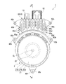
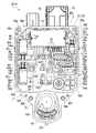
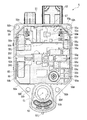
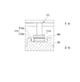
図1〜図3は、実施形態に係る制御装置3を備える電動モータ1の一例を示す。
図1〜図3を参照し、電動モータ1は、ブラシレスモータ2(被駆動体)と、ブラシレスモータ2を制御する制御装置3と、を備える。
尚、図中符号CLはブラシレスモータ2の出力軸20の軸線を示す。以下、軸線CLに沿う方向を「モータ軸方向」、軸線CLと直交する方向を「モータ径方向」、軸線CL回りに周回する方向を「モータ周方向」という。
又、図中符号V1はモータ軸方向の一方側、符号V2はモータ軸方向の他方側をそれぞれ示す。
Embodiments of the present invention will be described below with reference to the drawings.
<Whole electric motor>
1 to 3 show an example of an electric motor 1 including a
1 to 3, the electric motor 1 includes a brushless motor 2 (driven body) and a
In the figure, reference sign CL indicates the axis of the
In the figure, reference numeral V1 indicates one side in the motor axis direction, and reference numeral V2 indicates the other side in the motor axis direction.
<ブラシレスモータ>
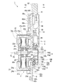
図2及び図3を参照し、ブラシレスモータ2は、軸線CLを形成する出力軸20と、出力軸20と共に回転可能なロータ21と、出力軸20と共にロータ21を回転させるための磁界を発生可能なステータ22とを備える。
<Brushless motor>
2 and 3, the
ロータ21は、円盤状の底壁21aと、底壁21aの外周端からモータ軸方向の一方側V1に延びると共にモータ軸方向の一方側V1に開口部21iを形成する円筒状の周壁21bと、周壁21bの開口部21i側の端部に径方向に延びる鍔部21dとを備える。底壁21aの径方向中心部には、出力軸20を挿通する円筒状のボス部21hが形成される。例えば、ボス部21hに出力軸20を圧入固定することで、出力軸20と共にロータ21が回転可能とされる。周壁21bの径方向内側面には、接着等によって複数のロータマグネット21cが設けられている。ロータ21は、ステータ22が発生する磁界を受けて出力軸20と共に回転可能とされる。
The
ステータ22は、ロータ21の周壁21bの径方向内側に配置される。ステータ22は、制御装置3の筐体8にボルト22dによって固定される。ステータ22の径方向内側には、出力軸20の軸受として機能する一対のベアリング23を嵌装するベアリングホルダ24が設けられ、ステータ22とともにボルト22dによって固定される。
The
ステータ22は、円筒状のステータコア22aと、ステータコア22aに径方向外向きに突設された複数のティース部に対して、モータ軸方向両側に装着される絶縁性のインシュレータ22bと、インシュレータ22b上に巻装される導電性のコイル22cとを備える。コイル22cは、U相、V相、W相の三相に対応する。本実施形態のブラシレスモータ2は、U相、V相、W相の三相のコイル22cを備えた三相ブラシレスモータである。
The
コイル22cの端末部は、ロータ21の開口部21i側から引き出され、前記開口部21i側に筐体8の開口80mを貫通するように配置されるバスバーユニット25に接続される。バスバーユニット25は、外部からの電力をコイル22cに供給する機能を有する。例えば、バスバーユニット25は、各相のコイル22cの巻始め端(不図示)と接続されるU相用バスバー、V相用バスバー及びW相用バスバーと、各相のコイル22cの巻終わり端(不図示)と接続される中性点用バスバーとを備える。各バスバーのうち、U〜W相用バスバーは、開口部21iから制御装置3に向けてモータ軸方向に沿うように延びる3つの給電端子25aを備える。各給電端子25aは、後述する三相バスバー121〜123のモータ側端部125(図7参照)に抵抗溶接等によって電気的に接続される。
The terminal portion of the
<制御装置>
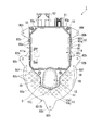
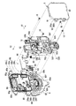
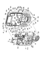
図4及び図5を併せて参照し、制御装置3は、複数のバスバー100(導電性板材)を含むターミナル4と、ターミナル4を埋設する樹脂製のベース部材5と、複数のバスバー100にそれぞれ電気的に接続される複数の電子素子60を含む電子部品6と、ブラシレスモータ2に電力を供給すると共にブラシレスモータ2の駆動を制御するパワーデバイス7と、ベース部材5が取り付けられる筐体8(図3参照)と、ベース部材5を覆う樹脂製のカバー9,10(本体カバー9及びターミナルカバー10)とを備える。
ここで、ターミナル4のうち、電子部品6を電気的に接続するものは請求項に記載の「第一ターミナル」に相当し、パワーデバイス7を電気的に接続するものは請求項に記載の「第二ターミナル」に相当する。
尚、図4及び図5においては、便宜上、筐体8及びカバー9,10の図示を省略する。図中符号30は、制御装置3のうち筐体8及びカバー9,10を除いた部分、即ちベース部材5の内部に複数のバスバー100が配設されたインサート成形部品(以下「バスバーモジュール」という。)を示す。
<Control device>
4 and 5 together, the
Here, among the
4 and 5, the
<ベース部材>
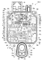
図6を併せて参照し、ベース部材5は、モータ軸方向に厚みを有し、且つ、モータ軸方向から見た平面視で矩形板状をなすベース本体50を備える。ベース本体50は、平面視で、第一辺50aと、第一辺50aに対向する第二辺50bと、第一辺50a及び第二辺50bに直交する第三辺50cと、第一辺50aに隣接して傾斜する第四辺50dと、第四辺50dに対向し且つ第二辺50bに隣接して傾斜する第五辺50eとを有する。
図6においては、便宜上、ベース部材5のうち窓部55、貫通孔50h及び開口部53h等の開口を除く本体部分をハッチングで示す。
<Base member>
Referring also to FIG. 6, the
In FIG. 6, for convenience, the main body portion of the
以下、ベース部材5の厚み方向の一方側を「第一面側」、ベース部材5の第一面側とは反対側を「第二面側」とする。尚、「第一面側」はベース部材5におけるモータ軸方向の一方側に相当し、「第二面側」はベース部材5におけるモータ軸方向の他方側に相当する。
Hereinafter, one side in the thickness direction of the
ベース部材5は、平面視で、ベース本体50の第三辺50cから突出する第一コネクタ51及び第二コネクタ52と、ベース本体50の第三辺50cとは反対側から突出するターミナル接続部53とを更に備える。例えば、ベース部材5には、複数のバスバー100(図7参照)が配設されており、例えば、樹脂等の絶縁材料を用いたインサート成形によって、ベース部材5の内部に埋設されている。
The
ベース本体50とターミナル接続部53との間には、平面視で第四辺50d及び第五辺50eのそれぞれに沿うように延びると共にターミナル接続部53の外周部に沿うように延びる輪郭を有するフランジ部50fが形成される。
ベース本体50には、第一辺50a及び第二辺50bと第三辺50cとが交差する角部に、平面視で頂部に角丸を有する三角形状をなすフランジ部50gが形成される。
フランジ部50f,50gには、ベース部材5の厚み方向に開口する貫通孔50hが形成される。
ターミナル接続部53には、出力軸20に臨む位置に、ベース部材5の厚み方向に開口する開口部53hと、3つのターミナル接続孔53mが形成される。このターミナル接続孔53mは、ブラシレスモータ2の3つの給電端子25aをターミナル接続部53内に導き、後述する三相バスバー121〜123のモータ側端部125と面どうしで付き合わせて電気的に溶接するためのものである。
A flange having a contour extending between the
In the
A through
In the
ベース本体50には、電子部品6及びパワーデバイス7とバスバー100との接続部を露出させる窓部55と、電子部品6が配置される電子部品配置部56と、パワーデバイス7が配置されるパワーデバイス配置部57とが形成される。
In the
<窓部>
窓部55は、ベース部材5の厚み方向にベース本体50を貫通するように形成される。窓部55は、ベース本体50の所定位置に配置される複数の窓部55a〜55oを備える。
ここで、窓部55のうち、電子部品6を電気的に接続する第一ターミナルを露出させるものは請求項に記載の「第一窓部」に相当し、パワーデバイス7を電気的に接続する第二ターミナルを露出させるものは請求項に記載の「第二窓部」に相当する。
<Window part>
The
Here, in the
以下、ベース部材5の厚み方向を単に「厚み方向」、平面視で厚み方向に直交し且つ第一辺50a及び第二辺50bに平行なベース部材5の高さ方向を単に「高さ方向」、平面視で厚み方向に直交し且つ第三辺50cに平行なベース部材5の幅方向を単に「幅方向」ということがある。
Hereinafter, the thickness direction of the
窓部55aは、平面視で幅方向に延びる長方形状をなすと共に、幅方向の中央部で開口部53h寄りに配置される。
窓部55b,55cは、平面視でそれぞれ幅方向に延びる長方形状をなすと共に、窓部55aよりも第三辺50c側で幅方向に並ぶように配置される。
窓部55dは、平面視で幅方向に延びる長方形状をなすと共に、窓部55bよりも第一辺50a寄りに配置される。
窓部55eは、平面視で高さ方向に延びる長方形状をなすと共に、窓部55dの窓部55b側に配置される。
窓部55fは、平面視で矩形状をなすと共に、窓部55bと窓部55eとの間の部分よりも第三辺50c側に配置される。
窓部55gは、平面視で矩形状をなすと共に、第一辺50a寄りで窓部55dよりも第三辺50c側に配置される。
The
The
The
The
The
The
窓部55hは、平面視で幅方向に延びるクランク状をなすと共に、窓部55cよりも第二辺50b寄りに配置される。
窓部55iは、平面視で第二辺50b側から窓部55g近傍まで至るように窓部55hよりも幅方向に長く延びると共に、窓部55hよりも第三辺50c側に配置される。
窓部55jは、平面視で高さ方向に延びるクランク状をなすと共に、幅方向の中央部で第三辺50c寄りに配置される。
窓部55kは、平面視で高さ方向に延びるクランク状をなすと共に、窓部55jの第二辺50b側に配置される。
The
The
The
The
窓部55lは、平面視で三角形状をなすと共に、第一辺50a寄りで窓部55gよりも第三辺50c側に配置される。
窓部55mは、平面視で矩形状をなすと共に、窓部55jの第一辺50a側に配置される。
窓部55nは、平面視で幅方向に延びる長方形状をなすと共に、窓部55mよりも第三辺50c側で且つ窓部55jの第一辺50a側に配置される。
窓部55oは、平面視で幅方向に対して傾斜して延びる台形状をなすと共に、第二コネクタ52寄りに配置される。
The window portion 55l has a triangular shape in plan view and is disposed closer to the
The
The
The window portion 55o has a trapezoidal shape extending obliquely with respect to the width direction in plan view, and is disposed closer to the
<電子部品配置部>
電子部品配置部56は、電子部品6を収容するように、ベース本体50に厚み方向の内側に窪む凹状に形成される。電子部品配置部56は、電子部品6が配置される六つの配置部56a〜56f(第一配置部56a、第二配置部56b、第三配置部56c、第四配置部56d、第五配置部56e及び第六配置部56f)を備える。
<Electronic component placement section>
The electronic component placement portion 56 is formed in a concave shape that is recessed inward in the thickness direction in the
第一配置部56a、第二配置部56b、第三配置部56c、第四配置部56d及び第五配置部56eはベース本体50の第二面側から第一面側に向けて窪む凹状をなし、第六配置部56f(図4参照)はベース本体50の第一面側から第二面側に向けて窪む凹状をなす。
第一配置部56aは、平面視で幅方向に延びる長方形状をなすと共に、窓部55d〜55gに囲まれる部分に配置される。
第二配置部56bは、平面視で幅方向に延びる長方形状をなすと共に、窓部55f,55g,55iに囲まれる部分に第一配置部56aと高さ方向で並ぶように配置される。
第三配置部56cは、平面視で高さ方向に延びる長方形状をなすと共に、窓部55g,55i,55lに囲まれる部分に第一辺50aに沿うように配置される。
第四配置部56dは、平面視で高さ方向に延びる長方形状をなすと共に、窓部55hの第五辺50eの側に第二辺50bに沿うように配置される。
第五配置部56eは、平面視で高さ方向に延びる長方形状をなすと共に、窓部55iの第三辺50cの側に第二辺50bに沿うように配置される。
第六配置部56f(図4参照)は、平面視で高さ方向に延びる長方形状をなすと共に、窓部55iに囲まれる部分に第五配置部56eの窓部55i側に配置される。
The
The
The
The
The
The
The
<パワーデバイス配置部>
パワーデバイス配置部57は、パワーデバイス7を収容するように、ベース本体50に厚み方向の内側に窪む凹状に形成される。パワーデバイス配置部57は、平面視で幅方向に延びる長方形状をなすと共に、窓部55j,55k,55m,55n,55oと重なる部分を含み且つ第三辺50cに沿うように配置される。
<Power device placement section>
The power
<バスバー>
図7を併せて参照し、複数のバスバー100は、信号系ターミナルバスバー101〜106と、二つのパワー用ターミナルバスバー111,112(第一パワー用ターミナルバスバー111及び第二パワー用ターミナルバスバー112)と、三相バスバー121〜123と、パワー用バスバー131と、グランドバスバー141と、を備える。例えば、複数のバスバー100は、それぞれ銅等の金属板材を所望の形状に屈曲することによって形成される。
<Bus bar>
Referring also to FIG. 7, the plurality of
信号系ターミナルバスバー101〜106は、第一コネクタ51の近傍に配置される。信号系ターミナルバスバー101〜106は、それぞれベース本体50の窓部55i内に露出するパワーデバイス側端部107と、第一コネクタ51内に露出するコネクタ側端部108と、窓部55j内に露出する信号系ターミナルバスバー102,103の接続部102a,103aと、信号系ターミナルバスバー105の接続部105a,105bとを備える。
The signal system terminal bus bars 101 to 106 are arranged in the vicinity of the
信号系ターミナルバスバー101〜106は、上位ECU(Electronic Control Unit)等の外部機器との通信ラインとして設けられる。例えば、信号系ターミナルバスバー101〜106は、ブラシレスモータ2の目標回転数の入力、ブラシレスモータ2の回転数の出力、パワーデバイス7の機能設定等に用いられる。
Signal system terminal bus bars 101 to 106 are provided as communication lines with external devices such as a host ECU (Electronic Control Unit). For example, the signal system terminal bus bars 101 to 106 are used for input of the target rotational speed of the
第一パワー用ターミナルバスバー111は、ベース本体50の第二コネクタ52から第一辺50aに沿う領域において第一配置部56a、第二配置部56b及び第三配置部56cを迂回するように配置される。第一パワー用ターミナルバスバー111は、ベース本体50の窓部55d内に露出する接地端部111aと、第二コネクタ52内に露出するコネクタ側端部111bと、接地端部111a及びコネクタ側端部111bとを連結する部分からベース本体50の窓部55g,55l,55o内にそれぞれ露出する舌片部111c,111d,111eとを備える。第一パワー用ターミナルバスバー111には、雑防素子61が選択的に接続可能とされる。
ここで、接地端部111a、第一パワー用ターミナルバスバー111、窓部55dは、それぞれ請求項に記載の「接地端子」、「接地ターミナル」、「接地窓部」に相当する。
The first power
Here, the grounding
第二パワー用ターミナルバスバー112は、信号系ターミナルバスバー101〜106と第一パワー用ターミナルバスバー111との間に配置される。第二パワー用ターミナルバスバー112は、ベース本体50の窓部55i内に露出する舌片部112aと、第二コネクタ52内に露出するコネクタ側端部112bと、舌片部112a及びコネクタ側端部112bとを連結する部分からベース本体50の窓部55l内に露出する舌片部112cとを備える。
The second power
三相バスバー121〜123は、ターミナル接続部53の近傍に配置される。三相バスバー121〜123は、それぞれベース本体50の窓部55i内に露出するパワーデバイス側端部124と、ターミナル接続部53の3つのターミナル接続孔53m内に露出するモータ側端部125と、パワーデバイス側端部124及びモータ側端部125とを連結する部分からベース本体50の窓部55a,55b内にそれぞれ露出する舌片部126,127とを備える。
図中符号120は、三相バスバー121〜123のうちパワーデバイス側端部124及びモータ側端部125とを連結する部分(以下「バスバー本体」という。)を示す。バスバー本体120の板厚方向は、厚み方向と略平行をなす。即ち、バスバー本体120の板厚方向は、モータ軸方向と略平行をなす。以下、バスバー本体120の板厚方向を単に「板厚方向」という。
Three-
パワー用バスバー131は、信号系ターミナルバスバー101〜106よりもターミナル接続部53側の位置で、且つ、厚み方向で三相バスバー121〜123よりも第一面側(図7の紙面奥側)に位置すると共に幅方向に延びるように配置される。パワー用バスバー131は、ベース本体50の窓部55i内に露出するパワーデバイス側端部132及び舌片部133,134と、窓部55f内に露出する舌片部135と、窓部55h内に露出する舌片部136,137とを備える。
The power bus bar 131 is located closer to the
グランドバスバー141は、厚み方向でパワー用バスバー131よりも第一面側(図7の紙面奥側)に位置すると共に幅方向に延びるように配置される。グランドバスバー141は、ベース本体50の窓部55i内に露出するパワーデバイス側端部142及び舌片部143と、窓部55e内に露出する舌片部144と、窓部55h内に露出する舌片部145,146とを備える。
The ground bus bar 141 is disposed so as to be positioned on the first surface side (the back side in FIG. 7) from the power bus bar 131 in the thickness direction and to extend in the width direction. The ground bus bar 141 includes a power
<電子素子>
複数の電子素子60は、雑防素子61、一対の平滑コンデンサ65,66、レジスタ67及びダイオード68を備える。
雑防素子61は、Xコンデンサ62及び二つのチョークコイル63,64(第一チョークコイル63及び第二チョークコイル64)を備える。
Xコンデンサ62は、ラジオノイズを抑制するために設けられる。例えば、Xコンデンサ62は、円筒状の電解コンデンサである。Xコンデンサ62は、ベース本体50の第三配置部56cに配置される。Xコンデンサ62の中心軸線は、ベース本体50の第一辺50aに沿うように配置される。
<Electronic element>
The plurality of
The noise prevention element 61 includes an
The
Xコンデンサ62は、一端面から突出する一対のリード線を有する。前記一対のリード線の先端は、窓部55l内に配置され、例えば抵抗溶接等によって、窓部55lから露出した第一パワー用ターミナルバスバー111の舌片部111dと第二パワー用ターミナルバスバー112の舌片部112cとにそれぞれ電気的に接続される。
The
第一チョークコイル63及び第二チョークコイル64は、ラジオノイズを抑制するために設けられる。例えば、第一チョークコイル63及び第二チョークコイル64は、フェライト等の磁性材料で形成される円柱状のコアに、導線を巻きつけたものである。
第一チョークコイル63はベース本体50の第一配置部56aに配置され、第二チョークコイル64はベース本体50の第二配置部56bに配置される。第一チョークコイル63及び第二チョークコイル64のコアの中心軸線は、幅方向に沿うように配置される。
The
The
第一チョークコイル63の導線の一端部は、窓部55g内に配置され、例えば抵抗溶接等によって、窓部55gから露出した第一パワー用ターミナルバスバー111の舌片部111cに電気的に接続される。第一チョークコイル63の導線の他端部は、窓部55e内に配置され、例えば抵抗溶接等によって、窓部55eから露出したグランドバスバー141の舌片部144に電気的に接続される。
One end portion of the conducting wire of the
第二チョークコイル64の導線の一端部は、窓部55i内に配置され、例えば抵抗溶接等によって、窓部55iから露出した第二パワー用ターミナルバスバー112の舌片部112aに電気的に接続される。第二チョークコイル64の導線の他端部は、窓部55f内に配置され、例えば抵抗溶接等によって、窓部55fから露出したパワー用バスバー131の舌片部135に電気的に接続される。
One end portion of the conducting wire of the
一対の平滑コンデンサ65,66は、ブラシレスモータ2の駆動に伴い生じる電圧の変化を抑制するために設けられる。例えば、一対の平滑コンデンサ65,66は、Xコンデンサ62と同様、円筒状の電解コンデンサである。一方の平滑コンデンサ65は第四配置部56dに配置され、他方の平滑コンデンサ66は第五配置部56eに配置される。各平滑コンデンサ65,66の中心軸線は、ベース本体50の第二辺50bに沿うように配置される。
The pair of smoothing
一対の平滑コンデンサ65,66は、それぞれ一端面から突出する一対のリード線を有する。
一方の平滑コンデンサ65における一対のリード線の先端は、窓部55h内に配置され、例えば抵抗溶接等によって、窓部55hから露出したパワー用バスバー131の舌片部136とグランドバスバー141の舌片部145とにそれぞれ電気的に接続される。
他方の平滑コンデンサ66における一対のリード線の先端は、窓部55i内に配置され、例えば抵抗溶接等によって、窓部55iから露出したパワー用バスバー131の舌片部133とグランドバスバー141の舌片部143とにそれぞれ電気的に接続される。
Each of the pair of smoothing
The tips of the pair of lead wires in one smoothing
The tip ends of the pair of lead wires in the other smoothing
レジスタ67は、第六配置部56fに配置される。レジスタ67は、ベース本体50の第二辺50bに沿うように延びる。例えば、レジスタ67とダイオード68とは、平滑コンデンサ65,66を充電する電流を制限するための電流制限回路として機能する。
レジスタ67の両端部は、窓部55i内に配置される。レジスタ67の一端部は、例えば抵抗溶接等によって、窓部55iから露出したパワー用バスバー131の舌片部134に電気的に接続される。レジスタ67の他端部は、例えば抵抗溶接等によって、窓部55iから露出した信号系ターミナルバスバー104の舌片部104aに電気的に接続される。
The
Both ends of the
ダイオード68は、窓部55kに埋設される不図示の土台に配置される。ダイオード68は、ベース本体50の第二辺50bに沿うように延びる。
ダイオード68の一端部は、例えば抵抗溶接等によって、信号系ターミナルバスバー104の舌片部104bに電気的に接続される。ダイオード68の他端部は、例えば抵抗溶接等によって、窓部55kから露出した信号系ターミナルバスバー101の舌片部101bに電気的に接続される。
The
One end of the
<パワーデバイス>
図5を併せて参照し、パワーデバイス7は、パワーデバイス配置部57に配置される。パワーデバイス7は、幅方向に延びる矩形板状に形成される。例えば、パワーデバイス7は、エポキシ樹脂等のモールド体の内部に集積回路等が内蔵されることよって構成される。例えば、前記集積回路には、FET(Field effect Transistor:電界効果トランジスタ)及びIGBT(Insulated Gate Bipolar Transistor:絶縁ゲートバイポーラトランジスタ)等のスイッチング素子を含む電子素子が含まれる。
<Power device>
Referring also to FIG. 5, the
パワーデバイス7の一側面には、リード線を含む端子列7aが設けられる。端子列7aを構成する各端子は、窓部55i内に露出し、例えば抵抗溶接等によって、窓部55iから露出したバスバー100の各パワーデバイス側端部107,124,132,142にそれぞれ電気的に接続される。
On one side surface of the
<接続回路>
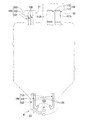
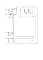
図8を併せて参照し、パワーデバイス7には、上述したXコンデンサ62、チョークコイル63,64、平滑コンデンサ65,66、レジスタ67及びダイオード68が電子素子60が電気的に接続される。
尚、図中符号69は、例えば、セラミックコンデンサ等のノイズ対策用のコンデンサを示す。ノイズ対策が必要な場合を想定して、ベース本体50のパワーデバイス7が配置されるパワーデバイス配置部57のベース本体裏面(第二面側)には、二ヶ所の拡張用電子部品配置部50kが設けられており、このスペースにコンデンサ69(電子部品)が配設可能に構成されている。この拡張用電子部品配置部50kに配される電子部品から突出する一対のリード線は、一方が窓部55jから露出する信号系ターミナルバスバー105の接続部105a,105bに電気的に接続可能に構成され、他方が窓部55jから露出する信号系ターミナルバスバー102,103の接続部102a,103aにそれぞれ電気的に接続可能に構成されている。尚、バスバー100の所定位置に他のコンデンサ69の実装部を設けるようにしてもよい。これにより、制御装置3に求められるタフネス要件が変わってノイズ対策が必要となった場合には、拡張用電子部品配置部50kにコンデンサ69を実装することで、所望のノイズ対策が可能となる。尚、パワーデバイス配置部57のベース本体裏面(第二面側)以外のバスバー100の所定位置に、別の拡張用電子部品配置部を設けるようにしてもよい。
<Connection circuit>
Referring also to FIG. 8, the
<浮き上がり防止部>
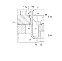
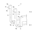
図5を参照し、ベース部材5には、パワーデバイス7がベース部材5のパワーデバイス配置部57から浮き上がることを防止する浮き上がり防止部70が形成される。浮き上がり防止部70には、パワーデバイス7をベース部材5に係止する係止部71が設けられる。係止部71は、平面視で幅方向に延びる長方形状をなすパワーデバイス7の四隅の近傍に、パワーデバイス7の短辺方向に沿うように両側一対ずつ合計四つ設けられる。
パワーデバイス7の複数の端子列7aをバスバー100の各パワーデバイス側端部107,124,132,142とそれぞれ電気的に抵抗溶接する場合、窓部55iの貫通方向のそれぞれから一対の電極を接続部に当接させ、一対の電極間に電流を流して行うが、この際、その電極の当接圧によって、パワーデバイス7がベース部材5のパワーデバイス配置部57から浮き上がろうとする事象が発生し、抵抗溶接の作業性が低下することがあるが、本実施形態の場合、パワーデバイス配置部57に浮き上がり防止部70が形成されているため、抵抗溶接の作業性を向上させることができる。
尚、浮き上がり防止部70には、係止部71に限らず、ボルト等の締結部材が設けられてもよい。
<Floating prevention part>
Referring to FIG. 5, the
When the plurality of
Note that the lifting
<係止部>
図9及び図10を併せて参照し、係止部71は、ベース本体50の第一面側に設けられる基部72と、基部72から第二面側に向けて延びる脚部73と、脚部73の末端部から第二面側に位置するパワーデバイス7の側に突出してパワーデバイス7を係止する爪部74とを備える。
<Locking part>
9 and 10 together, the locking
脚部73の基端部(基部72寄りの部分)には、図9の断面視で円弧状に湾曲する湾曲部73aが形成される。
爪部74は、図9の断面視で、パワーデバイス7の平坦な一面7s(第二面側の面)に当接する平坦な当接部74aと、厚み方向に対して傾斜するテーパ部74bとを備える。
パワーデバイス7の係止部71に臨む側面には、幅方向外側に向けて凸のV字状をなすように傾斜するテーパ部7eが形成される。
A
The
A tapered
<筐体>
図11及び図12を併せて参照し、筐体8は、モータ軸方向で、ベース本体50の外形に沿う形状をなす筐体本体80と、ターミナル接続部53の外形に沿う形状をなすモータ連結部81と、ブラシレスモータ2の外形に沿う形状をなすモータブラケット部82とを備える。例えば、筐体8は、アルミニウム等の熱伝導性の良い金属材料によって形成される。
<Case>
Referring to FIGS. 11 and 12 together, the
<筐体本体>
図1〜図3を併せて参照し、筐体本体80は、モータ軸方向の他方側V2に平坦な面を有する本体ベース部80aと、本体ベース部80aの幅方向両端部から幅方向外側に突出する複数(例えば本実施形態では幅方向両端に一つずつ計二つ)のフランジ部80bと、本体ベース部80aの面上にモータ軸方向の他方側に向けて突出する複数のピン型の放熱フィン80cと、図2における上下の隣接する複数の放熱フィン80cの間を繋ぐように直線状に延びる連結リブ80dと、本体ベース部80aの幅方向両端部から幅方向外側に突出する複数の凸型の放熱フィン80eとを備える。フランジ部80bには、モータ軸方向に開口する貫通孔80hが形成される。
<Case body>
1 to 3 together, the housing
<モータ連結部>
モータ連結部81には、モータ軸方向に開口する開口部81hが形成される。モータ連結部81において開口部81hに臨む部分には、ブラシレスモータ2が一体的に連結されるモータ連結ボス部81aが設けられる。
<Motor connection part>
The
<モータブラケット部>
モータブラケット部82は、モータ軸方向の一方側に平坦な面を有するベース部82aと、ベース部82aの外周部からモータ径方向の外側に突出する複数(例えば本実施形態では三つ)のフランジ部82bと、ベース部82aの面上にモータ軸方向の一方側V1に向けて突出する複数のピン型の放熱フィン82cとを備える。フランジ部82bには、モータ軸方向に開口する貫通孔82hが形成される。
図2中、上側に位置する2つのフランジ部82bの間には、ベース部80aとモータカバー部82との間に、ロータ21(鍔部21d)の外形に沿って設けられた多角形状の壁部82dが設けられている。
このように、本体筐体80には、放熱フィン80c、連結リブ80d、放熱フィン80e、放熱フィン82cが設けられることによって、筐体本体80の表面積を増やすことができ、制御装置3やブラシレスモータ2の熱を効果的に放熱することができる。
又、本体ベース部80aには、隣接する複数の放熱フィン80c同士を天地縦方向に連結する連結リブ80dが形成され、ベース部80aとモータカバー部82との間に、ロータ21(鍔部21d)の外形に沿って設けられた壁部82dが設けられているため、本体筐体80に付着した雨水は、本体ベース部80a上に留まることなく下方に誘導されて、さらに、図2中、壁部82dに沿って左右に誘導されて本体筐体80から排水されることになって、この経路からの雨水によるブラスレスモータ2の被水が効果的に軽減される。
<Motor bracket part>
The
In FIG. 2, between the two
As described above, the
The main
<ベース部材取付部>
図12を併せて参照し、筐体本体80とモータ連結部81との間には、モータ軸方向でベース部材5のフランジ部50fと対向する部位に、ベース部材取付部80fが形成される。
筐体本体80には、モータ軸方向でベース部材5のフランジ部50gと対向する部位に、ベース部材取付部80gが形成される。
ベース部材取付部80f,80gには、モータ軸方向に開口する取付孔80kが形成される。
<Base member mounting part>
Referring also to FIG. 12, a base
A base
The base
例えば、ベース部材5の各フランジ部50f,50gの貫通孔50hにボルト18を挿通し、筐体8の各ベース部材取付部80f,80gの取付孔80kにボルト18をねじ込むことによって、ベース部材5を筐体8に締結固定することができる。
For example, the
<本体カバー>
図1及び図11を併せて参照し、本体カバー9は、モータ軸方向から見て、ベース本体50の外形に沿う矩形状をなす。本体カバー9は、ベース本体50に板厚方向の一方側から接近してベース本体50を覆う。尚、「板厚方向の一方側」は、モータ軸方向の一方側に相当する。
本体カバー9は、ベース本体50を板厚方向の一方側から覆う天板部90と、天板部90からベース本体50に向けて起立すると共にモータ軸方向から見てベース本体50を囲む矩形環状のカバー壁部91とを備える。
<Main body cover>
1 and 11 together, the
The
天板部90には、本体カバー9をベース本体50に係止する係止部92が設けられる。係止部92は、天板部90の幅方向両端部に複数(例えば本実施形態では幅方向両端に二つずつ計四つ)設けられる。
係止部92は、天板部90からベース本体50に向けて延びる一対の脚部92aと、一対の脚部92aの末端部を連結する連結部92bとを備える。
ベース本体50には、係止部92の連結部92bに板厚方向の一方側から係止する爪部50jが設けられる。爪部50jは、本体カバー9の係止部92に対向するように、ベース本体50の幅方向両端部に複数(例えば本実施形態では幅方向両端に二つずつ計四つ)設けられる。
The
The locking
The
<ターミナルカバー>
図1及び図3を併せて参照し、ターミナルカバー10は、モータ軸方向から見て、ターミナル接続部53の外形に沿う形状をなす。ターミナルカバー10は、ターミナル接続部53に板厚方向の一方側から接近してターミナル接続部53を覆う。ターミナルカバー10は、三相バスバー121〜123のモータ側端部125と、出力軸20の締結部20jとを覆う位置に配置され、ブラシレスモータ2の3つの給電端子25aと対応するモータ側端部125との電気的接続部を覆蓋するものである。ターミナル接続部53とターミナルカバー10との間には、環状のシール材40が設けられる。
<Terminal cover>
1 and 3 together, the
ターミナルカバー10は、ターミナル接続部53を板厚方向の一方側から覆う天板部11と、天板部11からターミナル接続部53に向けて起立すると共に板厚方向から見てターミナル接続部53を囲む環状のカバー壁部12とを備える。
ターミナル接続部53は、カバー壁部12の外周側にシール材40を介して接する環状のベース壁部53aを備える。
ターミナルカバー10は、カバー壁部12及びベース壁部53aの径方向でシール材40を圧縮した状態で、ターミナル接続部53に取り付けられる。
尚、カバー壁部12及びベース壁部53aの径方向は、板厚方向に直交する方向(カバー壁部12及びベース壁部53aが対向する方向)に相当する。
The
The
The
The radial direction of the
天板部11には、ターミナルカバー10をターミナル接続部53に係止する係止部13,14(第一係止部13及び第二係止部14)が設けられる。
第一係止部13は、天板部11の外側からターミナル接続部53に向けて延びる一対の第一脚部13aと、一対の第一脚部13aの末端部を連結する第一連結部13bとを備える。
ターミナル接続部53には、第一係止部13の第一連結部13bに板厚方向の一方側から係止する第一爪部53jが設けられる。
第二係止部14は、天板部11の内側で且つ出力軸20の締結部20jに臨む側からターミナル接続部53に向けて延びる一対の第二脚部14aと、一対の第二脚部14aの末端部を連結する第二連結部14bとを備える。
ターミナル接続部53には、第二係止部14の第二連結部14bに板厚方向の一方側から係止する第二爪部53kが設けられる。
The
The
The
The
The
<凹部>
図11及び図12を併せて参照し、筐体本体80には、複数の電子素子60及びターミナル4の一部と対向する位置で窪む複数の第一凹部86と、パワーデバイス7と対向する位置で窪む第二凹部87とが形成される。
ここで、第一凹部及び第二凹部は、請求項に記載の「凹部」に相当する。
図11においては、便宜上、凹部に設けられる熱伝導材をハッチングで示す。
<Recess>
Referring to FIGS. 11 and 12 together, the
Here, the first concave portion and the second concave portion correspond to the “concave portion” recited in the claims.
In FIG. 11, for convenience, the heat conductive material provided in the concave portion is indicated by hatching.
複数の第一凹部86は、Xコンデンサ62と対向する位置で窪むXコンデンサ用凹部86a、二つのチョークコイル63,64と対向する位置で窪むチョークコイル用凹部86b、一対の平滑コンデンサ65,66とそれぞれ対向する位置で窪む一対の平滑コンデンサ用凹部86c、86d、第一パワー用ターミナルバスバー111の接地端部111aと対向する位置で窪む接地端部用凹部86e、三相バスバー121〜123の一対の舌片部126と対向する位置で窪む一対のV相用凹部86f及びW相用凹部86g、及び三相バスバー121〜123の舌片部127と対向する位置で窪むU相用凹部86hを備える。Xコンデンサ62、二つのチョークコイル63,64及び一対の平滑コンデンサ65,66は、レジスタ67及びダイオード68よりも高い発熱性を有する。
ここで、複数の電子素子60のうち、Xコンデンサ62、二つのチョークコイル63,64及び一対の平滑コンデンサ65,66は、請求項に記載の「第二電子素子」に相当する。又、複数の電子素子60のうち、レジスタ67及びダイオード68は、請求項に記載の「第一電子素子」に相当する。
The plurality of first recesses 86 include an
Here, among the plurality of
<熱伝導材>
第一凹部86には第一熱伝導材88が充填され、第二凹部87には第二熱伝導材89が充填される。第一熱伝導材88及び第二熱伝導材89は、ベース部材5よりも高い熱伝導率を有する。例えば、第一熱伝導材88及び第二熱伝導材89は、エポキシ系接着剤にアルミナフィラーを混在させたものを用いる。筐体8は、第一凹部86に設けた第一熱伝導材88及び第二凹部87に設けた第二熱伝導材89を介してベース部材5に固定される。
ここで、第一熱伝導材88及び第二熱伝導材89は、請求項に記載の「熱伝導材」に相当する。
<Heat conduction material>
The first concave portion 86 is filled with the first thermal
Here, the first heat
複数の第一熱伝導材88は、Xコンデンサ用凹部86aに設けられるXコンデンサ用熱伝導材88a、チョークコイル用凹部86bに設けられるチョークコイル用熱伝導材88b、一対の平滑コンデンサ用凹部86c、86dにそれぞれ設けられる一対の平滑コンデンサ用熱伝導材88c,88d、接地端部用凹部86eに設けられる接地端部用熱伝導材88e、一対のV相用凹部86f及びW相用凹部86gにそれぞれ設けられる一対のV相用熱伝導材88f及びW相用熱伝導材88g、及びU相用凹部86hに設けられるU相用熱伝導材88hを備える。
The plurality of first thermal
Xコンデンサ用熱伝導材88aの厚みは、例えば2.80mm以上且つ3.50mm以下の範囲の値とし、本実施形態では3.15mmとする。
チョークコイル用熱伝導材88bの厚みは、例えば2.60mm以上且つ2.80mm以下の範囲の値とし、本実施形態では2.70mmとする。
一対の平滑コンデンサ用熱伝導材88c,88dの厚みは、それぞれ例えば2.30mm以上且つ2.40mm以下の範囲の値とし、本実施形態では2.35mmとする。
接地端部用熱伝導材88eの厚みは、例えば1.83mm以上且つ3.15mm以下の範囲の値とし、本実施形態では2.49mmとする。
一対のV相用熱伝導材88f及びW相用熱伝導材88gの厚みは、それぞれ例えば1.70mm以上且つ3.24mm以下の範囲の値とし、本実施形態では2.47mmとする。
U相用熱伝導材88hの厚みは、例えば1.70mm以上且つ2.82mm以下の範囲の値とし、本実施形態では2.26mmとする。
パワーデバイス7用の第二熱伝導材89の厚みは、例えば0.65mm以上且つ1.65mm以下の範囲の値とし、本実施形態では1.15mmとする。
このように、第一熱伝導材88及び第二熱伝導材89の厚みを、各電子素子60及びパワーデバイス7ごとに規定することによって、各電子素子60及びパワーデバイス7ごとに適した絶縁性を確保できる。
The thickness of the
The thickness of the choke coil thermal
The thicknesses of the pair of smoothing capacitor thermal
The thickness of the thermal
The thicknesses of the pair of V-phase heat
The thickness of the U-phase heat
The thickness of the second heat
As described above, by defining the thicknesses of the first thermal
尚、熱伝導材88,89は、シリコーン系接着剤等の放熱特性に優れる他の材料を用いてもよい。
又、熱伝導材88,89は、PBT(polybutylene terephthalate)等の樹脂材料を用いてもよい。これにより、優れた絶縁特性を発揮できる。
又、熱伝導材88,89は、凹部及び電子素子等の表面に対して、優れた濡れ広がり性および接着性を有してもよい。これにより、凹部及び電子素子から接着剤が剥離することを抑制できるため、優れた耐振性及び放熱特性を確保できる。
又、熱伝導材88,89は、放熱シートと固定用接着剤とを組み合わせたり、放熱ゲルと固定用接着剤とを組み合わせたりしてもよい。
The
Further, the heat
Moreover, the heat
Further, the heat
<コンタクトプレート>
図12及び図13を併せて参照し、バスバーモジュール30を筐体8に取り付けるときには、接地端部用凹部86eにコンタクトプレート115を配置した状態で取り付ける。
コンタクトプレート115は、導電性及び弾性変形可能な部材を用いる。例えば、コンタクトプレート115は、銅等の金属片を折り曲げ加工することによって形成される。
コンタクトプレート115は、バスバーモジュール30に向けて凸をなして湾曲する弾性変形部115aと、弾性変形部115aの幅方向外端から幅方向内側に延びる一対の支持片115bとを備える。
<Contact plate>
12 and 13 together, when the
The
The
コンタクトプレート115は、弾性変形部115aをバスバーモジュール30側に向けた状態で、接地端部用凹部86eに配置される。この状態で、バスバーモジュール30を筐体8に取り付けると、弾性変形部115aが第一パワー用ターミナルバスバー111の接地端部111aとの当接によって弾性変形し、モータ軸方向に沿う方向に潰される。
これにより、コンタクトプレート115のバネ力で接地端部111aを筐体8に電気的に接続できる。例えば、他のグランド接続方法としては、バスバーをねじで締め付け固定する方法があるが、ねじ締付けによる応力及び冷熱衝撃による応力がバスバーにかかる懸念があった。これに対し、本実施形態によれば、ねじ締付けが不要であるため、ねじ締付けによる応力がバスバー100にかかる懸念を排除できる。又、弾性変形部115aの弾性変形によって冷熱衝撃による応力を吸収できるため、冷熱衝撃による応力がバスバー100にかかる懸念も排除できる。
The
Thereby, the ground end 111 a can be electrically connected to the
以上説明したように、上記実施形態は、複数のバスバー100を含むターミナル4と、ターミナル4が配設されるベース部材5と、ターミナル4に電気的に接続される複数の電子素子60を含む電子部品6と、を備える制御装置3であって、ベース部材5には、ターミナル4の一部を露出させる窓部55がベース部材5の厚み方向に貫通するように形成されるとともに、拡張用電子部品配置部50kが設けられており、電子部品6は、窓部55から露出したターミナル4に電気的に接続されるとともに、拡張用電子部品配置部50kによって、複数のバスバー100間に選択的に電子部品69を電気的接続可能とされている。
As described above, in the above embodiment, the
この構成によれば、ターミナル4が配設されるベース部材5にターミナル4の一部を露出させる窓部55が形成されることで、窓部55から露出した所定のターミナル4に電子部品6を選択的に接続することができるとともに、拡張用電子部品配置部50kによって、複数のバスバー100間に選択的に電子部品69を電気的接続可能となっているので、制御装置3に求められるノイズ等のタフネス要件に応じて、適宜、電子部品69の追加によって対応可能となるため、設計自由度を高めることができる。又、電子部品6が窓部55から露出したターミナル4に電気的に接続されることで、回路基板を必要としない構成となるため、回路基板を設ける場合と比較して、制御の仕様変更の場合であっても仕様毎に回路基板を変更する必要が無いため、部品コストを削減することができる。又、窓部55がベース部材5の厚み方向に貫通するように形成されることで、窓部55に抵抗溶接機等の接続機器を挿通し易くなるため、全加工工程の中でターミナル4と電子部品6との接続工程の占める割合が大きい場合であっても、加工時間を短縮することができる。従って、設計自由度を高めつつ部品コストの削減及び加工時間の短縮を図ることができる。
According to this configuration, the
又、上記実施形態では、電子部品6が第一窓部から露出した第一ターミナルに電気的に接続され、パワーデバイス7が第二窓部から露出した第二ターミナルに電気的に接続されることで、電子部品6及びパワーデバイス7をまとめて配置することができるため、設計自由度を高めつつ部品コストの削減及び加工時間の短縮を効果的に図ることができる。
Moreover, in the said embodiment, the
又、上記実施形態では、第一パワー用ターミナルバスバー111(接地ターミナル)には雑防素子61が選択的に接続可能とされることで、仕様に応じて雑防素子61を配置することができるため、ノイズ対策が必要な場合であってもノイズ要件を満足させることができる。 In the above embodiment, the noise preventing element 61 can be selectively connected to the first power terminal bus bar 111 (grounding terminal), so that the noise preventing element 61 can be arranged according to the specifications. Therefore, even if noise countermeasures are required, the noise requirements can be satisfied.
又、上記実施形態では、電子部品6が窓部55から露出したターミナル4に溶接結合されることで、電子部品6をはんだ付けする場合と比較して、加工時間の短縮を効果的に図ることができる。
In the above embodiment, the
又、上記実施形態では、ベース部材5にはパワーデバイス7がベース部材5から浮き上がることを防止する浮き上がり防止部70が設けられることで、パワーデバイス7をベース部材5にしっかりと固定することができる。例えば、パワーデバイス7を第二窓部から露出した第二ターミナルに溶接結合する場合であっても、パワーデバイス7がベース部材5から浮き上がることを防止することができる。
Moreover, in the said embodiment, the
又、上記実施形態では、ベース部材5にはパワーデバイス7をベース部材5に係止する係止部71が設けられることで、ボルト等の締結部材を用いる場合と比較して、パワーデバイス7をベース部材5に容易に係止することができるため、取付工数を削減することができる。
Further, in the above embodiment, the
又、上記実施形態では、係止部71が、ベース部材5の第一面側に設けられる基部72と、基部72からベース部材5の第二面側に向けて延びる脚部73と、脚部73の末端部から第二面側に位置するパワーデバイス7の側に突出してパワーデバイス7を係止する爪部74とを備えることで、脚部73のたわみを利用しつつ爪部74をパワーデバイス7に引っ掛けることによって、パワーデバイス7をベース部材5に容易に係止することができる。又、脚部73がベース部材5の第一面側の基部72から第二面側に向けて延びることで、ベース部材5の厚みを利用して脚部73の長さを十分に確保することができ、脚部73のたわみの作用を効果的に発揮することができる。
更に、脚部73の基端部には湾曲部73aが形成されることで、湾曲部73aを利用して、脚部73のたわみの作用を効果的に発揮することができる。
又、爪部74がパワーデバイス7の平坦な一面7sに当接する平坦な当接部74aを備えることで、爪部74の平坦な当接部74aをパワーデバイス7の平坦な一面7sに当接させることができるため、パワーデバイス7をベース部材5に安定して係止することができる。
又、爪部74が厚み方向に対して傾斜するテーパ部74bを備えることで、爪部74のテーパ部74bに沿ってパワーデバイス7の側面を摺動させることができるため、パワーデバイス7をベース部材5に容易に係止すると共に、脚部73のたわみの作用を効果的に発揮することができる。
又、パワーデバイス7の係止部71に臨む側面には、幅方向外側に向けて凸のV字状をなすように傾斜するテーパ部7eが形成されることで、パワーデバイス7の側面のテーパ部7eに沿って摺動させることができるため、パワーデバイス7をベース部材5に更に容易に係止すると共に、脚部73のたわみの作用を更に効果的に発揮することができる。
Moreover, in the said embodiment, the latching | locking
Furthermore, since the
Further, the
Moreover, since the
Further, a
又、上記実施形態では、ベース部材5に取り付けられると共にベース部材5よりも高い熱伝導率を有する筐体8を更に備えることで、冷却装置を別個に設ける場合と比較して、簡単な構成で放熱性を向上することができる。
Moreover, in the said embodiment, it is simple structure compared with the case where a cooling device is provided separately by further providing the housing | casing 8 which is attached to the
又、上記実施形態では、筐体8には少なくとも第二電子素子と対向する位置で窪む凹部が形成され、筐体8が凹部に設けた熱伝導材を介してベース部材5に固定されることで、第二電子素子が過度に発熱した場合であっても、第二電子素子を効果的に放熱することができる。
Moreover, in the said embodiment, the recessed part which becomes depressed at the position facing the 2nd electronic element at least in the housing | casing 8 is formed, and the housing | casing 8 is fixed to the
又、上記実施形態では、凹部が少なくとも第二電子素子と対向する位置で窪む第一凹部86と、パワーデバイス7と対向する位置で窪む第二凹部87とを備え、熱伝導材が第一凹部86に設けられる第一熱伝導材88と、第二凹部87に設けられる第二熱伝導材89とを備えることで、第二電子素子及びパワーデバイス7が過度に発熱した場合であっても、これらを効果的に放熱することができる。
In the above embodiment, the first recess 86 is recessed at a position facing at least the second electronic element, and the
又、上記実施形態では、筐体8は被駆動体としてのブラシレスモータ2が一体的に連結されるモータ連結部81を備えることで、制御装置3とブラシレスモータ2とを一体化した構成において、設計自由度を高めつつ部品コストの削減及び加工時間の短縮を図ることができる。
In the above embodiment, the
尚、この発明の技術範囲は上記の実施形態に限られるものではなく、本発明の趣旨を逸脱しない範囲において種々の変更を加えることが可能である。 The technical scope of the present invention is not limited to the above embodiment, and various modifications can be made without departing from the spirit of the present invention.
又、上記実施形態においては、バスバー100と電子部品6及びパワーデバイス7との接続を抵抗溶接により行ったが、これに限らず、例えばTIG溶接等のアーク溶接やレーザ溶接等により行ってもよい。
In the above embodiment, the
又、ベース部材5、筐体8、本体カバー9、ターミナルカバー10、ブラシレスモータ2、バスバー100等の材質や形状等は、上記実施形態に限定されない。例えば、バスバー100をアルミニウムにより形成してもよい。又、筐体8を鉄(炭素鋼)等の金属材料によって形成してもよい。
The materials, shapes, and the like of the
その他、本発明の趣旨を逸脱しない範囲で、上記した実施の形態における構成要素を周知の構成要素に置き換えることは適宜可能である。 In addition, it is possible to appropriately replace the components in the above-described embodiments with known components without departing from the spirit of the present invention.
2 ブラシレスモータ(被駆動体、モータ)
3 制御装置
4 ターミナル
5 ベース部材
6 電子部品
7 パワーデバイス
8 筐体
55 窓部
55d 窓部(接地窓部)
60 電子素子
61 雑防素子
69 コンデンサ(電子部品)
70 浮き上がり防止部
71 係止部
72 基部
73 脚部
74 爪部
81 モータ連結部
86 第一凹部(凹部)
87 第二凹部(凹部)
88 第一熱伝導材(熱伝導材)
89 第二熱伝導材(熱伝導材)
100 バスバー(導電性板材)
111 第一パワー用ターミナルバスバー(接地ターミナル)
111a 接地端部(接地端子)
2 Brushless motor (driven body, motor)
3
60 Electronic element 61
70
87 Second recess (recess)
88 1st heat conduction material (heat conduction material)
89 Second heat conduction material (heat conduction material)
100 bus bar (conductive plate)
111 1st power terminal bus bar (grounding terminal)
111a Grounding end (grounding terminal)
Claims (9)
前記ベース部材には、前記ターミナルの一部を露出させる窓部が前記ベース部材の厚み方向に貫通するように形成されるとともに、拡張用電子部品配置部が設けられており、
前記電子部品は、前記窓部から露出した前記ターミナルに電気的に接続されるとともに、前記拡張用電子部品配置部によって、前記複数のターミナル間に選択的に電子部品を電気的接続可能とされ、
前記ベース部材に取り付けられると共に、前記ベース部材よりも高い熱伝導率を有する筐体を更に備え、
前記複数の電子素子は、第一電子素子と、前記第一電子素子よりも高い発熱性を有する第二電子素子とを備え、
前記筐体には、前記第一電子素子及び前記第二電子素子のうち少なくとも前記第二電子素子と対向する位置で窪む凹部が形成され、
前記凹部には、前記ベース部材よりも高い熱伝導率を有する熱伝導材が設けられ、
前記筐体は、前記凹部に設けた前記熱伝導材を介して前記ベース部材に固定されることを特徴とする制御装置。 A control device comprising: a terminal including a plurality of conductive plate members; a base member on which the terminal is disposed; and an electronic component including a plurality of electronic elements electrically connected to the terminal,
The base member is formed so that a window portion exposing a part of the terminal penetrates in the thickness direction of the base member, and an expansion electronic component placement portion is provided,
The electronic component is electrically connected to the terminal exposed from the window, and can be selectively electrically connected between the plurality of terminals by the expansion electronic component placement unit .
A housing attached to the base member and having a higher thermal conductivity than the base member;
The plurality of electronic elements includes a first electronic element and a second electronic element having a higher exothermic property than the first electronic element,
The housing is formed with a recess that is recessed at a position facing at least the second electronic element of the first electronic element and the second electronic element,
The recess is provided with a heat conductive material having a higher thermal conductivity than the base member,
The control device , wherein the casing is fixed to the base member via the heat conducting material provided in the recess .
前記ターミナルは、前記電子部品を電気的に接続する第一ターミナルと、前記パワーデバイスを電気的に接続する第二ターミナルとを備え、
前記窓部は、前記第一ターミナルの一部を露出させる第一窓部と、前記第二ターミナルの一部を露出させる第二窓部とを備え、
前記電子部品は、前記第一窓部から露出した前記第一ターミナルに電気的に接続され、
前記パワーデバイスは、前記第二窓部から露出した前記第二ターミナルに電気的に接続されることを特徴とする請求項1に記載の制御装置。 A power device for supplying power to the driven body and controlling the driving of the driven body;
The terminal includes a first terminal that electrically connects the electronic components, and a second terminal that electrically connects the power device,
The window includes a first window that exposes a portion of the first terminal, and a second window that exposes a portion of the second terminal,
The electronic component is electrically connected to the first terminal exposed from the first window;
The control device according to claim 1, wherein the power device is electrically connected to the second terminal exposed from the second window.
前記第一窓部は、前記接地端子を露出させる接地窓部を備え、
前記接地ターミナルには、雑防素子が選択的に接続可能とされることを特徴とする請求項2に記載の制御装置。 The first terminal includes a ground terminal having a ground terminal;
The first window includes a ground window that exposes the ground terminal;
The control device according to claim 2, wherein a noise prevention element is selectively connectable to the ground terminal.
前記ベース部材には、前記パワーデバイスが前記ベース部材から浮き上がることを防止する浮き上がり防止部が設けられることを特徴とする請求項1から4までの何れか一項に記載の制御装置。 A power device for supplying power to the driven body and controlling the driving of the driven body;
5. The control device according to claim 1, wherein the base member is provided with a lifting prevention unit that prevents the power device from floating from the base member. 6.
前記ベース部材の第一面側に設けられる基部と、
前記基部から前記ベース部材の第一面側とは反対側の第二面側に向けて延びる脚部と、
前記脚部の末端部から前記第二面側に位置するパワーデバイスの側に突出して前記パワーデバイスを係止する爪部と、を備えることを特徴とする請求項6に記載の制御装置。 The locking portion is
A base provided on the first surface side of the base member;
Leg portions extending from the base portion toward the second surface side opposite to the first surface side of the base member;
The control device according to claim 6, further comprising: a claw portion that protrudes from a distal end portion of the leg portion toward the power device located on the second surface side and engages the power device.
前記凹部は、前記第一電子素子及び前記第二電子素子のうち少なくとも前記第二電子素子と対向する位置で窪む第一凹部と、前記パワーデバイスと対向する位置で窪む第二凹部とを備え、
前記熱伝導材は、前記第一凹部に設けられる第一熱伝導材と、前記第二凹部に設けられる第二熱伝導材とを備えることを特徴とする請求項1から7までの何れか一項に記載の制御装置。 A power device for supplying power to the driven body and controlling the driving of the driven body;
The concave portion includes a first concave portion that is depressed at a position facing at least the second electronic element among the first electronic element and the second electronic element, and a second concave portion that is depressed at a position facing the power device. Prepared,
The said heat conductive material is provided with the 1st heat conductive material provided in said 1st recessed part, and the 2nd heat conductive material provided in said 2nd recessed part, The any one of Claim 1-7 characterized by the above-mentioned. The control device according to item .
Priority Applications (5)
| Application Number | Priority Date | Filing Date | Title |
|---|---|---|---|
| JP2015110918A JP6488198B2 (en) | 2015-05-29 | 2015-05-29 | Control device |
| EP16803250.6A EP3306812B1 (en) | 2015-05-29 | 2016-05-27 | Control device |
| PCT/JP2016/065733 WO2016194815A1 (en) | 2015-05-29 | 2016-05-27 | Control device |
| US15/560,199 US10848035B2 (en) | 2015-05-29 | 2016-05-27 | Control apparatus that controls driving of a driven body |
| CN201680030645.7A CN107735939B (en) | 2015-05-29 | 2016-05-27 | control device |
Applications Claiming Priority (1)
| Application Number | Priority Date | Filing Date | Title |
|---|---|---|---|
| JP2015110918A JP6488198B2 (en) | 2015-05-29 | 2015-05-29 | Control device |
Publications (2)
| Publication Number | Publication Date |
|---|---|
| JP2016226181A JP2016226181A (en) | 2016-12-28 |
| JP6488198B2 true JP6488198B2 (en) | 2019-03-20 |
Family
ID=57441148
Family Applications (1)
| Application Number | Title | Priority Date | Filing Date |
|---|---|---|---|
| JP2015110918A Active JP6488198B2 (en) | 2015-05-29 | 2015-05-29 | Control device |
Country Status (5)
| Country | Link |
|---|---|
| US (1) | US10848035B2 (en) |
| EP (1) | EP3306812B1 (en) |
| JP (1) | JP6488198B2 (en) |
| CN (1) | CN107735939B (en) |
| WO (1) | WO2016194815A1 (en) |
Families Citing this family (5)
| Publication number | Priority date | Publication date | Assignee | Title |
|---|---|---|---|---|
| JP6575930B2 (en) * | 2016-06-02 | 2019-09-18 | 株式会社オートネットワーク技術研究所 | Board unit |
| US11451116B2 (en) * | 2017-12-27 | 2022-09-20 | Lg Innotek Co., Ltd. | Motor |
| JP7522684B2 (en) * | 2021-03-04 | 2024-07-25 | 株式会社ミツバ | Drive device, motor device and blower device |
| EP4597806A4 (en) * | 2022-09-29 | 2025-10-22 | Mitsubishi Electric Mobility Corp | ELECTRIC LATHE AND METHOD FOR MANUFACTURING SAME |
| DE102024104519A1 (en) * | 2024-02-19 | 2025-08-21 | Voith Patent Gmbh | Motor unit |
Family Cites Families (10)
| Publication number | Priority date | Publication date | Assignee | Title |
|---|---|---|---|---|
| JP4471752B2 (en) * | 2004-07-06 | 2010-06-02 | 日立オートモティブシステムズ株式会社 | Electric power steering control device and electric power steering system |
| JP4756935B2 (en) * | 2005-06-29 | 2011-08-24 | 本田技研工業株式会社 | Inverter unit with capacitor |
| FR2916011B1 (en) | 2007-05-10 | 2010-12-10 | Somfy Sas | TUBULAR ACTUATOR FOR DRIVING A SCREEN AND METHOD FOR MANUFACTURING SUCH ACTUATOR |
| JP2011223644A (en) | 2010-04-02 | 2011-11-04 | Jtekt Corp | Assembly method of control apparatus |
| WO2013008266A1 (en) * | 2011-07-08 | 2013-01-17 | 三菱電機株式会社 | Electric motor |
| JP6034068B2 (en) | 2011-07-25 | 2016-11-30 | 日本電産サンキョー株式会社 | Eddy current pump device |
| JP6001966B2 (en) | 2012-09-05 | 2016-10-05 | アスモ株式会社 | Vehicle motor unit |
| WO2014104121A1 (en) * | 2012-12-28 | 2014-07-03 | 株式会社ミツバ | Electric motor and electric pump |
| JP2014161209A (en) * | 2013-01-25 | 2014-09-04 | Mitsuba Corp | Electric motor and electric pump |
| JP2015082935A (en) | 2013-10-23 | 2015-04-27 | 日本電産サンキョー株式会社 | Motor and method of connecting winding to terminal pin in motor |
-
2015
- 2015-05-29 JP JP2015110918A patent/JP6488198B2/en active Active
-
2016
- 2016-05-27 US US15/560,199 patent/US10848035B2/en active Active
- 2016-05-27 WO PCT/JP2016/065733 patent/WO2016194815A1/en not_active Ceased
- 2016-05-27 EP EP16803250.6A patent/EP3306812B1/en active Active
- 2016-05-27 CN CN201680030645.7A patent/CN107735939B/en active Active
Also Published As
| Publication number | Publication date |
|---|---|
| EP3306812B1 (en) | 2020-04-29 |
| CN107735939A (en) | 2018-02-23 |
| US20180076695A1 (en) | 2018-03-15 |
| EP3306812A1 (en) | 2018-04-11 |
| JP2016226181A (en) | 2016-12-28 |
| CN107735939B (en) | 2020-10-16 |
| EP3306812A4 (en) | 2019-01-16 |
| WO2016194815A1 (en) | 2016-12-08 |
| US10848035B2 (en) | 2020-11-24 |
Similar Documents
| Publication | Publication Date | Title |
|---|---|---|
| US8436500B2 (en) | Semiconductor module and motorized equipment using the same | |
| JP5160185B2 (en) | Inverter device | |
| JP6488198B2 (en) | Control device | |
| JP5414944B2 (en) | Motor drive device for electric power steering device | |
| JP5160186B2 (en) | Inverter device | |
| CN107041165A (en) | Control unit and electric power steering device using the control unit | |
| JP4538474B2 (en) | Inverter device | |
| JP6960573B2 (en) | Busbar unit and motor drive | |
| JP6983338B2 (en) | Electric drive | |
| JP6922435B2 (en) | Electric drive device and electric power steering device | |
| JP5523044B2 (en) | Drive control device and motor unit | |
| JP2014050238A (en) | Rotary electric machine | |
| JP5011061B2 (en) | Inverter device | |
| JP6447736B2 (en) | Rotating electrical terminal block | |
| JP7282612B2 (en) | Control device and motor device | |
| JP6496794B1 (en) | Component mounting body and electronic equipment | |
| JP6467478B1 (en) | Component mounting body and electronic equipment | |
| CN109923770B (en) | Electric compressor | |
| JP6313940B2 (en) | Electronic control unit | |
| JP5927996B2 (en) | Motor wiring structure | |
| JP2020178479A (en) | Inverter unit | |
| JP2008290675A (en) | Electric power steering device | |
| JP2018117463A (en) | Rotating electric machine stator | |
| JP2011083062A (en) | Motor unit | |
| JP2017059300A (en) | Terminal block device |
Legal Events
| Date | Code | Title | Description |
|---|---|---|---|
| A621 | Written request for application examination |
Free format text: JAPANESE INTERMEDIATE CODE: A621 Effective date: 20171123 |
|
| RD03 | Notification of appointment of power of attorney |
Free format text: JAPANESE INTERMEDIATE CODE: A7423 Effective date: 20181026 |
|
| A131 | Notification of reasons for refusal |
Free format text: JAPANESE INTERMEDIATE CODE: A131 Effective date: 20181204 |
|
| A521 | Request for written amendment filed |
Free format text: JAPANESE INTERMEDIATE CODE: A523 Effective date: 20181220 |
|
| TRDD | Decision of grant or rejection written | ||
| A01 | Written decision to grant a patent or to grant a registration (utility model) |
Free format text: JAPANESE INTERMEDIATE CODE: A01 Effective date: 20190205 |
|
| A61 | First payment of annual fees (during grant procedure) |
Free format text: JAPANESE INTERMEDIATE CODE: A61 Effective date: 20190225 |
|
| R150 | Certificate of patent or registration of utility model |
Ref document number: 6488198 Country of ref document: JP Free format text: JAPANESE INTERMEDIATE CODE: R150 |