JP6485742B2 - Sheet storage device and image forming apparatus - Google Patents
Sheet storage device and image forming apparatus Download PDFInfo
- Publication number
- JP6485742B2 JP6485742B2 JP2015099215A JP2015099215A JP6485742B2 JP 6485742 B2 JP6485742 B2 JP 6485742B2 JP 2015099215 A JP2015099215 A JP 2015099215A JP 2015099215 A JP2015099215 A JP 2015099215A JP 6485742 B2 JP6485742 B2 JP 6485742B2
- Authority
- JP
- Japan
- Prior art keywords
- stopper
- operation member
- main body
- release
- paper feed
- Prior art date
- Legal status (The legal status is an assumption and is not a legal conclusion. Google has not performed a legal analysis and makes no representation as to the accuracy of the status listed.)
- Active
Links
Images


Classifications
-
- B—PERFORMING OPERATIONS; TRANSPORTING
- B65—CONVEYING; PACKING; STORING; HANDLING THIN OR FILAMENTARY MATERIAL
- B65H—HANDLING THIN OR FILAMENTARY MATERIAL, e.g. SHEETS, WEBS, CABLES
- B65H1/00—Supports or magazines for piles from which articles are to be separated
- B65H1/04—Supports or magazines for piles from which articles are to be separated adapted to support articles substantially horizontally, e.g. for separation from top of pile
-
- B—PERFORMING OPERATIONS; TRANSPORTING
- B65—CONVEYING; PACKING; STORING; HANDLING THIN OR FILAMENTARY MATERIAL
- B65H—HANDLING THIN OR FILAMENTARY MATERIAL, e.g. SHEETS, WEBS, CABLES
- B65H1/00—Supports or magazines for piles from which articles are to be separated
- B65H1/26—Supports or magazines for piles from which articles are to be separated with auxiliary supports to facilitate introduction or renewal of the pile
- B65H1/266—Support fully or partially removable from the handling machine, e.g. cassette, drawer
-
- B—PERFORMING OPERATIONS; TRANSPORTING
- B65—CONVEYING; PACKING; STORING; HANDLING THIN OR FILAMENTARY MATERIAL
- B65H—HANDLING THIN OR FILAMENTARY MATERIAL, e.g. SHEETS, WEBS, CABLES
- B65H2402/00—Constructional details of the handling apparatus
- B65H2402/50—Machine elements
- B65H2402/51—Joints, e.g. riveted or magnetic joints
-
- B—PERFORMING OPERATIONS; TRANSPORTING
- B65—CONVEYING; PACKING; STORING; HANDLING THIN OR FILAMENTARY MATERIAL
- B65H—HANDLING THIN OR FILAMENTARY MATERIAL, e.g. SHEETS, WEBS, CABLES
- B65H2402/00—Constructional details of the handling apparatus
- B65H2402/60—Coupling, adapter or locking means
-
- B—PERFORMING OPERATIONS; TRANSPORTING
- B65—CONVEYING; PACKING; STORING; HANDLING THIN OR FILAMENTARY MATERIAL
- B65H—HANDLING THIN OR FILAMENTARY MATERIAL, e.g. SHEETS, WEBS, CABLES
- B65H2405/00—Parts for holding the handled material
- B65H2405/10—Cassettes, holders, bins, decks, trays, supports or magazines for sheets stacked substantially horizontally
- B65H2405/11—Parts and details thereof
- B65H2405/113—Front, i.e. portion adjacent to the feeding / delivering side
-
- B—PERFORMING OPERATIONS; TRANSPORTING
- B65—CONVEYING; PACKING; STORING; HANDLING THIN OR FILAMENTARY MATERIAL
- B65H—HANDLING THIN OR FILAMENTARY MATERIAL, e.g. SHEETS, WEBS, CABLES
- B65H2405/00—Parts for holding the handled material
- B65H2405/10—Cassettes, holders, bins, decks, trays, supports or magazines for sheets stacked substantially horizontally
- B65H2405/11—Parts and details thereof
- B65H2405/114—Side, i.e. portion parallel to the feeding / delivering direction
-
- B—PERFORMING OPERATIONS; TRANSPORTING
- B65—CONVEYING; PACKING; STORING; HANDLING THIN OR FILAMENTARY MATERIAL
- B65H—HANDLING THIN OR FILAMENTARY MATERIAL, e.g. SHEETS, WEBS, CABLES
- B65H2405/00—Parts for holding the handled material
- B65H2405/10—Cassettes, holders, bins, decks, trays, supports or magazines for sheets stacked substantially horizontally
- B65H2405/12—Parts to be handled by user
- B65H2405/121—Locking means
-
- B—PERFORMING OPERATIONS; TRANSPORTING
- B65—CONVEYING; PACKING; STORING; HANDLING THIN OR FILAMENTARY MATERIAL
- B65H—HANDLING THIN OR FILAMENTARY MATERIAL, e.g. SHEETS, WEBS, CABLES
- B65H2801/00—Application field
- B65H2801/03—Image reproduction devices
- B65H2801/06—Office-type machines, e.g. photocopiers
Landscapes
- Engineering & Computer Science (AREA)
- Mechanical Engineering (AREA)
- Sheets, Magazines, And Separation Thereof (AREA)
Description
本発明は、シート収納装置および画像形成装置に関するものである。 The present invention relates to a sheet storage device and an image forming apparatus.
従来から、用紙が積載収容された給紙カセットを装置本体に対して引き出し可能に構成したシート収納装置を備えた画像形成装置が知られている。 2. Description of the Related Art Conventionally, there has been known an image forming apparatus including a sheet storage device configured such that a paper feeding cassette on which sheets are stacked and stored can be pulled out of the apparatus main body.
特許文献1には、装置本体に設けたストッパたるピンに係合するフックと、フックのピンとの係合を解除する解除ボタンとを備えたシート収納装置が記載されている。上記フックは、先端に鉤状部を備え、他端が回動自在に給紙カセットに支持されている。給紙カセットが装置本体に装着されているとき、上記フックの鉤状部が、給紙カセットの引き出し方向上流側からピンに対向している。これにより、給紙カセットが引き出されようとすると、鉤状部がピンにあたり、給紙カセットが装置本体に止められる。 Japanese Patent Application Laid-Open No. 2004-228561 describes a sheet storage device that includes a hook that engages with a pin that is a stopper provided in the apparatus main body, and a release button that releases the engagement of the hook pin. The hook has a hook-shaped portion at the tip, and the other end is supported by the paper feed cassette so as to be rotatable. When the sheet cassette is mounted on the apparatus main body, the hook-shaped portion of the hook faces the pin from the upstream side in the pulling-out direction of the sheet cassette. As a result, when the paper feeding cassette is to be pulled out, the hook-shaped portion hits the pin, and the paper feeding cassette is stopped on the apparatus main body.
解除ボタンは、給紙カセットに移動可能に保持されており、解除ボタンを押すと、フックが解除ボタンの動きに連動して回動し、フック先端の鉤状部が、ピンと対向する対向位置から、退避位置へと移動し、フックのピンとの係合が外れる。これにより、引き出しユニットの装置本体に対する止めが外れて、給紙カセットが装置本体に対して引き出し可能となる。 The release button is movably held in the paper feed cassette. When the release button is pressed, the hook rotates in conjunction with the movement of the release button, and the hook-shaped portion at the tip of the hook moves from the opposite position facing the pin. Then, it moves to the retracted position and disengages from the hook pin. As a result, the drawer unit is released from the apparatus main body, and the paper feed cassette can be pulled out from the apparatus main body.
また、特許文献1に記載のシート収納装置には、解除禁止手段たるシリンダ錠が設けられている。このシリンダ錠には、フックの回動を規制する規制部材が設けられている。シリンダ錠の鍵穴に鍵を差し込んで、鍵によりシリンダ錠を回動させると、その回動により、退避位置からフックの回動を規制する規制位置へと規制部材が移動する。これにより、フックの鉤状部が対向位置から退避位置への移動ができなくなり、解除ボタンによる給紙カセットの装置本体に対する止めの解除が禁止される。 Further, the sheet storage device described in Patent Document 1 is provided with a cylinder lock as release prohibiting means. The cylinder lock is provided with a regulating member that regulates the rotation of the hook. When a key is inserted into the keyhole of the cylinder lock and the cylinder lock is rotated by the key, the restriction member moves from the retracted position to a restriction position that restricts the rotation of the hook. As a result, the hook-shaped portion of the hook cannot be moved from the facing position to the retracted position, and the release of the stop of the sheet feeding cassette with respect to the apparatus main body by the release button is prohibited.
しかしながら、特許文献1に記載のシート収納装置においては、給紙カセットが引き出されたときに、誤ってシリンダ錠の施錠が行われる場合がある。この場合、フックの鉤状部が、対向位置から退避位置へ移動不能な状態で、給紙カセットが装置本体に押し込まれていく。すると、フック先端の被ストッパ部たる鉤状部が装置本体内のストッパ部たるピンに突き当たると、給紙カセットをそれ以上装置本体に押し入れることができなくなり、給紙カセットが装着できないという課題がある。また、鉤状部がピンに突き当た状態で、給紙カセットをさらに装置に本体に押し入れようとすると、ピンやフックに大きな負荷が加わり、ピンやフックが破損してしまうという課題があった。 However, in the sheet storage device described in Patent Document 1, when the paper feeding cassette is pulled out, the cylinder lock may be erroneously locked. In this case, the paper feed cassette is pushed into the apparatus main body while the hook-shaped portion of the hook cannot move from the facing position to the retracted position. Then, when the hook-shaped part that is the stopper part at the tip of the hook hits the pin that is the stopper part in the apparatus main body, the paper cassette cannot be pushed into the apparatus main body any more, and the paper cassette cannot be mounted. is there. In addition, if the paper cassette is pushed into the main body with the hook-shaped portion being in contact with the pin, a large load is applied to the pin and the hook, and the pin and the hook are damaged. .
上記課題を解決するために、本発明は、装置本体に対して引き出し可能に構成された給紙カセットと、前記装置本体に設けたストッパ部に止められる被ストッパ部を有し、前記被ストッパ部が前記ストッパ部に止められる止め位置と止め解除位置との間を移動するように構成されたストッパ手段と、ユーザーの操作により第1の位置と第2の位置とを取り得るように前記給紙カセットに保持された操作部材と、前記操作部材の前記第1の位置から前記第2の位置への動きに連動して前記ストッパ手段を動作させ、前記被ストッパ部を、前記止め位置から前記止め解除位置へ移動させて前記給紙カセットの装置本体内への止めを解除する解除手段と、
前記操作部材の操作による前記給紙カセットの装置本体内への止めの解除ができないようにする解除禁止手段とを備えたシート収納装置であって、前記解除禁止手段は、シリンダ錠と、前記操作部材の前記第1の位置から前記第2の位置への移動を規制する規制部材とを備え、鍵でシリンダ錠を操作することで、前記規制部材を、前記操作部材の移動を規制する規制位置と、前記操作部材から退避した退避位置との間を移動するように構成し、前記規制部材は、前記規制位置にあるとき、前記操作部材に当接して、前記操作部材の前記第2の位置への移動を規制するものであって、前記規制部材の前記操作部材との当接面とは反対側の面に当接して、前記規制部材が前記第2の位置側へ変形しないように押さえる押さえ部材を設け、前記操作部材は、前記解除手段を介して前記被ストッパ部材を動かす可動部を有し、前記解除手段は、前記可動部に収められ、前記操作部材が前記第1の位置から前記第2の位置へ移動する際に、前記可動部に当接して前記操作部材とともに前記第1の位置から前記第2の位置へ移動するリンク部材を有しており、前記リンク部材が、前記可動部に対して、前記操作部材の移動方向に所定の範囲で移動可能に構成したことを特徴とするものである。
In order to solve the above-described problems, the present invention includes a paper feed cassette configured to be drawable with respect to an apparatus main body, and a stoppered part that is stopped by a stopper provided in the apparatus main body. Stopper means configured to move between a stop position where the stopper is stopped by the stopper portion and a stop release position, and the paper feed so that the first position and the second position can be taken by a user operation. The operation member held in the cassette, and the stopper means are operated in conjunction with the movement of the operation member from the first position to the second position, and the stopper portion is moved from the stop position to the stop position. Release means for moving the release cassette to the release position and releasing the stop of the paper feed cassette in the apparatus body;
The sheet storage device includes release prohibiting means for preventing the release of the stop of the sheet feeding cassette into the apparatus main body by operation of the operation member, wherein the release prohibiting means includes a cylinder lock and the operation A regulating member that regulates movement of the member from the first position to the second position, and operates the cylinder lock with a key, thereby regulating the regulating member to regulate movement of the operating member. And the retracted position retracted from the operation member, and when the restriction member is in the restriction position, the contact member abuts on the operation member and the second position of the operation member The contact of the restricting member with the surface opposite to the contact surface with the operation member and pressing the restricting member so as not to be deformed to the second position side. Providing a holding member, the operation The material has a movable portion that moves the stopper member via the release means, the release means is housed in the movable portion, and the operation member moves from the first position to the second position. A link member that contacts the movable part and moves from the first position to the second position together with the operation member, and the link member is The operation member is configured to be movable within a predetermined range in the moving direction.
本発明によれば、解除禁止手段による解除禁止状態で給紙カセットが装置本体に押入れられても、給紙カセットを装置本体に装着することができ、また、ストッパ部や被ストッパ部が破損するのを防止することができる。 According to the present invention, even when the paper feed cassette is pushed into the apparatus main body in the state where the release prohibiting means is in the release prohibited state, the paper feed cassette can be attached to the apparatus main body, and the stopper portion and the stopper target portion are damaged. Can be prevented.
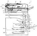
図1は本実施形態に係る画像形成装置の概略構成図である。 FIG. 1 is a schematic configuration diagram of an image forming apparatus according to the present embodiment.
図1に示すように、画像形成装置1は、装置本体の略中央部に配置された画像形成部100や、この画像形成部100の下方に配置された給紙部203や、画像形成装置1により画像形成を行うときに作業者が操作するための操作部13などを有している。
As shown in FIG. 1, the image forming apparatus 1 includes an
また、画像読取装置としての画像読取ユニット50は、画像形成部100の上に固定されたスキャナ150と、これに支持される原稿自動搬送装置(以下「ADF」という。)51とを有している。
The
給紙部203には、装置本体に対して着脱可能な給紙カセット109が2つ装着されており、それぞれに紙種の異なる用紙Pが収容されている。
Two
用紙Pは、給紙カセット109から給紙コロ111によって、給紙部203から排紙部11に至る略上下(鉛直)方向に延びる搬送路110に給紙される。次に、搬送ローラ112により搬送路110内を搬送され、画像形成部100にて画像形成され定着処理された後、排紙ローラ対5により排紙部11へ排紙される。
The paper P is fed by a paper feed roller 111 from a
画像形成部100には、図中矢印で示す反時計まわり方向へ回転駆動される像担持体としての感光体115や、感光体115に静電潜像を形成する光書込み装置116などが設けられている。
The
さらに、感光体115の周囲には、感光体115の反時計まわり方向へ順に、感光体115を均一に帯電する帯電装置としての帯電装置117が配設されている。
Further, a
また、感光体115上の静電潜像にトナーを付着させて可視像化する現像装置118、現像装置118によって形成されたトナー像を搬送されてきた用紙Pに転写する転写ローラ119が配設されている。
Further, a developing
さらには、転写後の感光体115に残存するトナー等を除去して感光体115をクリーニングするクリーニングユニット120なども配設されている。
Further, a
転写ローラ119と排紙部11との間には、転写ローラ119で用紙Pに転写されたトナー像を加熱及び加圧して、用紙Pに定着させる定着装置121が設けられている。
A
光書込み装置116は、スキャナ150からの画像データ、あるいは、パーソナルコンピュータなどから入力される画像情報に基づいて、感光体115の表面をレーザー光によって露光し光書込みを行って、感光体115の表面上に静電潜像を形成する。 The optical writing device 116 exposes the surface of the photoconductor 115 with laser light based on image data from the scanner 150 or image information input from a personal computer or the like, and performs optical writing to perform the optical writing. An electrostatic latent image is formed thereon.
用紙Pは、上下の給紙カセット109の何れか一方の給紙コロ111により選択的に給紙され、搬送ローラ112により搬送路110内を搬送される。
The paper P is selectively fed by one of the paper feed rollers 111 of the upper and lower
さらに、用紙Pは、転写ローラ119よりも用紙搬送方向上流側に設けられているレジストローラ対123にて一旦搬送が停止された後、所定のタイミングで転写ローラ119と感光体115とのニップ部にレジストローラ対123によって送り込まれる。そして、前記ニップ部で感光体115から用紙Pにトナー像が転写される。
Furthermore, after the conveyance of the paper P is temporarily stopped by the
前記ニップ部でトナー像が転写された用紙Pは定着装置121に搬送され、定着装置121で熱と圧力とによりトナー像が用紙Pに定着され、装置外に設けられた排紙部11に排紙ローラ対5によって排出される。
The paper P on which the toner image has been transferred at the nip is conveyed to the
本実施形態の画像形成装置1では両面印刷も可能であり、その場合は用紙Pのおもて面にトナー像が定着された後、分岐爪7で搬送経路を切り替えて反転ローラ対6側に用紙Pを搬送する。
In the image forming apparatus 1 of the present embodiment, double-sided printing is also possible. In this case, after the toner image is fixed on the front surface of the paper P, the conveyance path is switched by the branching
反転ローラ対6は、用紙Pを反転トレイ12に途中まで排出したのち逆回転し、用紙Pを両面搬送路8側へ送り込む。両面搬送路8に送り込まれた用紙Pは表裏が判定された状態で、レジストローラ対123の位置まで再度搬送される。
The reversing roller pair 6 discharges the paper P to the reversing
そして、レジストローラ対123から前記ニップ部に送り込まれた用紙Pの裏面に、感光体115からトナー像を転写した後、そのトナー像を定着装置121で用紙Pに定着し、排紙ローラ対5によって排紙部11に排出する。
Then, after transferring the toner image from the photosensitive member 115 to the back surface of the paper P sent to the nip portion from the
画像形成部100の上に固定されたスキャナ150やこれの上に固定されたADF51からなる画像読取ユニット50は、後述する2つの固定読取部や移動読取部152を有している。
An
移動読取部152は、原稿MSに接触するようにスキャナ150のケーシング上壁に固定された第二コンタクトガラス155の直下に配設されており、光源や、反射ミラーなどからなる光学系を図中左右方向に移動させることができる。
The
そして、光学系を図中左側から右側に移動させていく過程で、光源から発した光を第二コンタクトガラス155上に載置された原稿MSの下面で反射させた後、複数の反射ミラーを経由させて、スキャナ150に固定された画像読取センサ153で受光する。
Then, in the process of moving the optical system from the left side to the right side in the figure, after the light emitted from the light source is reflected by the lower surface of the document MS placed on the second contact glass 155, a plurality of reflecting mirrors are Then, the light is received by the
一方、画像読取ユニット50は固定読取部として、スキャナ150の内部に配設された第一固定読取部151と、ADF51内に配設された後述する第二固定読取部95とを有している。
On the other hand, the
光源、反射ミラー、CCD等の画像読取センサなどを有する第一固定読取部151は、原稿MSに接触するようにスキャナ150のケーシング上壁に固定された第一コンタクトガラス154の直下に配設されている。
A first
そして、ADF51によって搬送される原稿MSが第一コンタクトガラス154上を通過する際に、光源から発した光を原稿MSの第一面で順次反射させながら、複数の反射ミラーを経由させて画像読取センサ153で受光する。
Then, when the document MS conveyed by the ADF 51 passes over the
これにより、光源や反射ミラー等からなる光学系を移動させることなく、原稿MSの第一面を走査する。また、第二固定読取部95は、第一固定読取部151を通過した後の原稿MSの第二面を走査する。
Accordingly, the first surface of the document MS is scanned without moving the optical system including the light source and the reflection mirror. The second fixed reading unit 95 scans the second surface of the document MS after passing through the first
スキャナ150の上に配設されたADF51は、本体カバー52に、読取前の原稿MSを載置するための原稿載置台53、シート材としての原稿MSを搬送するための原稿搬送部54、読取後の原稿MSをスタックするための原稿スタック台55などを保持している。
An ADF 51 disposed on the scanner 150 includes a document placing table 53 for placing a document MS before reading on a
また、本実施形態の画像形成装置1には、両面搬送路8で紙詰まりが生じたときに、両面搬送路8内を外部に露出できるように装置本体に対して開放可能なカバー14が設けられている。また、図1に示すようにカバー14には、より多種の用紙Pを給紙できるよう手差し給紙装置15と手差しトレイ701が設けられている。
Further, the image forming apparatus 1 of the present embodiment is provided with a
手差しトレイ701はカバー14に対して開閉可能であり、図1ではカバー14に対して手差しトレイ701が開いた状態を示している。このように開いた状態の手差しトレイ701上に積載された用紙Pは、手差し給紙装置15によって画像形成装置1内に向けて搬送される。
The
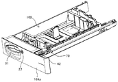
図2は、給紙カセット109の斜視図である。
給紙カセットの前側板109aには、取っ手部31が設けられている。また、給紙カセット109の側面には、装置本体に設けられたストッパ70と係わり合って給紙カセット109を装置本体に止める被ストッパ部材42が設けられている。給紙カセット109は、装置の手前側に引き出し可能に構成されている。
FIG. 2 is a perspective view of the
A
取っ手部31は、手前側に所定範囲移動可能に構成されており、後述するように給紙カセット109を装置本体から取っ手部31を掴んで引き出そうとすると、取っ手部31が引き出し方向に移動する。この移動により、被ストッパ部材42が動いて、ストッパ70からはずれ、給紙カセット109の装置本体に対する止めが外れる。これにより、給紙カセット109が引き出し可能となり、給紙カセット109が装置本体から引き出される。
The
画像形成装置は、例えば、大学の構内など、不特定多数の人に使用される場所に設置される場合がある。このように、不特定多数の人に使用される場合、給紙カセット109の用紙が盗られるおそれがある。従って、本実施形態では、給紙カセットの前側板109aにシリンダ錠22が設けられており、給紙カセット109を画像形成装置本体に施錠可能となっている。
An image forming apparatus may be installed in a place used by an unspecified number of people, such as a campus. As described above, when used by an unspecified number of people, the paper in the
給紙カセット109が装置本体に装着されている状態で、シリンダ錠22の鍵穴に鍵を差し込み、シリンダ錠22を回転させることで、給紙カセット109が、画像形成装置に施錠される。これにより、給紙カセット109内の用紙が盗られるような事態が生じるのを未然に防ぐことができる。
With the
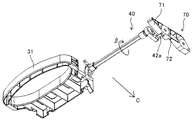
図3は、ストッパ70と、給紙カセットを装置本体に止めるためのストッパ手段たる被ストッパ部材42と、操作部材30と、操作部材の操作により給紙カセットの装置本体に対する止めを解除する解除機構40と、施錠装置20とを示す斜視図である。
操作部材30は、上述の取っ手部31を備えており、解除用スプリング36により給紙カセット109の押し入れ方向に付勢されている。
解除機構40は、給紙カセット109に回動自在に支持されており、リンク軸41と、リンク部材43とを備えている。リンク軸41の一端に被ストッパ部材が取り付けられている。解除機構40は、ストッパ用スプリング44により、図中矢印α方向に回動するように付勢されている。
FIG. 3 shows a
The
The
施錠装置20は、上述したシリンダ錠22と、規制部材21とを有しており、施錠すると、後述するように規制部材21の先端部21aが、操作部材30と対向して、操作部材30の第2の位置たる解除位置への移動を規制する。
The locking
図4は、操作部材30の斜視図である。
操作部材30は、給紙カセット109の引き出し方向に所定の範囲で移動可能に給紙カセット109に保持されている。操作部材30は、取っ手部31の他に、解除用スプリング36の一端が引っ掛けられるバネ受け部32が設けられている。また、操作部材30は、施錠装置20の規制部材21を規制位置へ案内するためのガイド部33、規制部材21が規制位置にあるとき、規制部材の先端部21aと対向して、解除位置への移動が規制される規制面34が設けられている。また、操作部材30は、解除機構40を介して被ストッパ部材を動かす可動部35が設けられている。
FIG. 4 is a perspective view of the
The
可動部35は、切り欠き形状であって、図2に示すように、解除機構40のリンク突起43aが、この可動部35に収まっている。また、可動部35の引き出し方向長さは、リンク突起43aの直径よりも長くなっており、リンク突起43aは、可動部35を所定の範囲で移動可能となっている。また、ガイド部33は、給紙カセットの下方に向うに連れて、装置奥側に位置するようなテーパ面となっている。本実施形態では、ガイド部33を平面としているが、凹面や凸面などの曲面としてもよい。
The
図5、解除機構40の斜視図である。
解除機構40は、リンク軸41と、リンク部材43とを有しており、給紙カセット109に回動自在に支持されている。被ストッパ部材42は、リンク軸41の一端に取り付けられており、リンク部材43は、リンク軸41の他端に取り付けられている。ストッパ手段たる被ストッパ部材42には、突起状の被ストッパ部42aを有しており、この被ストッパ部42aは、装置本体に設けられたストッパ70に止められる。
FIG. 5 is a perspective view of the
The
また、リンク部材43には、突起状のリンク突起43aと、ストッパ用スプリング44の一端が取り付けられるバネ受け43bが設けられている。
The
図6は、ストッパ70の斜視図である。
ストッパ70には、凹状の穴部72と、解除機構40被ストッパ部42aを穴部72へ案内するためのストッパガイド部71が設けられている。この穴部72の上下方向に延びる面が、被ストッパ部42aと給紙カセット109の引き出し方向下流側から対向して、給紙カセットを装置本体に止めるストッパ部72aである。ストッパガイド部71は、給紙カセット109の押し入れ方向(図中右側)にいくに従い下方の位置するようなテーパ面となっている。本実施形態では、ストッパガイド部71を平面としているが、凸面や凹面などの曲面としてもよい。
FIG. 6 is a perspective view of the
The
図7は、給紙カセット109が装置本体に装着されているときの操作部材30、解除機構40、被ストッパ部材42およびストッパ70を示す斜視図である。
図7は、給紙カセット109が装置本体に装着されているとき、被ストッパ部材42の被ストッパ部42aは、ストッパ70の穴部72に入り込んで、ストッパ部72aと対向する止め位置に位置している。これにより、給紙カセット109が引き出し方向へ移動しようとすると、被ストッパ部42aが、ストッパ部72aに突き当たり、給紙カセット109の引き出し方向へ移動が規制され、給紙カセット109が装置本体に止められる。
FIG. 7 is a perspective view showing the
FIG. 7 shows that when the
また、解除機構40は、ストッパ用スプリング44により図中矢印β方向と逆方向に付勢されている。これにより、被ストッパ部42aは、止め位置に位置するように付勢され、装置振動等により、被ストッパ部42aが穴部72から抜け出すことなく、安定的に止め位置に位置させることができる。これにより、振動等により給紙カセット109の止めが外れることなく、給紙カセット109を装置本体内に止めておくことができる。また、ストッパ用スプリング44で被ストッパ部材42を付勢して、被ストッパ部42aが止め位置に位置するようにしてもよい。
Further, the
給紙カセット109を装置本体から引き出すときは、取っ手部31を掴んで、取っ手部31を図中矢印A方向に引く。すると、操作部材30が、ホームポジションから解除位置に向って図中矢印A方向へと移動する。ストッパ用スプリング44の付勢力で、リンク突起43aは可動部35の引き出し方向上流側端部35aに突き当たっている。そのため、操作部材30が、図中矢印A方向に移動すると、可動部35の引き出し方向上流側端部35aが、リンク突起43aを図中矢印A方向に押し込む。すると、解除機構40が図中矢印β方向に回動し、被ストッパ部材42が解除機構40とともに回動する。その結果、図8に示すように、被ストッパ部材42の被ストッパ部42aが、穴部72から抜け出た止め解除位置へ移動し、給紙カセット109の装置本体に対する止めが解除される。操作部材30が解除位置まで移動すると、操作部材30が給紙カセット109に突き当たる。この状態から、取っ手部31をさらに引くと、操作部材30により給紙カセット109が押され、給紙カセット109が装置本体から引き出される。
When pulling out the
給紙カセット109を引き出して、取っ手部31から手を離すと、操作部材30は、解除用スプリング36の付勢力により給紙カセットの押し入れ方向に移動し、第1の位置たるホームポジションに戻る。また、解除機構40も、ストッパ用スプリング44の付勢力により、図中β方向とは反対方向に回動し、被ストッパ部材42が解除機構40とともに回動する。これにより、被ストッパ部42aが、移動可能位置から止め位置へと移動する。
When the
本実施形態では、操作部材30に取っ手部31を設けて、取っ手部31を掴んで給紙カセット109を装置本体から引き出す動作に連動して、操作部材30を解除位置へ移動させる構成としている。これにより、ユーザーは、給紙カセット109を装置本体から引き出すというワンアクションで、給紙カセット109の装置本体への止めの解除と、給紙カセット109の装置本体からの引き出しとを行うことができる。これにより、給紙カセット109の装置本体に対する止めを解除する動作と、給紙カセット109を装置本体から引き出すという動作のツーアクションで、給紙カセット109を装置本体から引き出す構成に比べて、給紙カセット109の引き出し作業を簡素化することができる。これにより、利便性の高い装置を提供することができる。
In the present embodiment, a
図9は、解錠状態のときの施錠装置20と操作部材30とを示す斜視図であり、図10は、施錠状態のときの施錠装置20と操作部材30とを示す斜視図である。
図9に示すように、解錠状態のとき、施錠装置20の規制部材21は、退避位置に位置しており、操作部材30は、図中矢印A方向に移動可能である。よって、解錠状態のとき、操作部材30をホームポジションから解除位置に移動させることができ、給紙カセット109の止めを解除することができる。
FIG. 9 is a perspective view showing the
As shown in FIG. 9, in the unlocked state, the regulating
鍵をシリンダ錠22の鍵穴に差し込んで、鍵を図9のγ方向に回すと、規制部材21がシリンダ錠22を支点にして図9の矢印B方向に回動する。そして、図10に示すように、鍵を90度回転させると、規制部材21が、操作部材30を規制する規制位置に位置し、先端部21aが、操作部材30の規制面34と給紙カセット109の引き出し方向下流側から対向する。これにより、操作部材30を解除位置に移動させるべく、操作部材30を給紙カセット109の引き出し方向に移動させようとすると、操作部材30の規制面34が規制部材21の先端部21aに突き当たり、操作部材30の解除位置への移動が規制される。その結果、操作部材30により解除機構40を回動させることができず、被ストッパ部42aが穴部72から抜き出ることがない。これにより、給紙カセット109が装置本体から引き出されることなく、給紙カセット109が施錠装置20により装置本体に施錠される。
When the key is inserted into the key hole of the
操作部材30は、上述したように、給紙カセット109の引き出し方向に移動可能に給紙カセット109に保持されている関係で、引き出し方向に多少のガタを有する。このため、操作部材30が、ホームポジションよりも引き出し方向下流側に位置する場合がある。この場合、規制部材21が操作部材30に引っ掛かって、規制部材21を規制位置まで回動できないおそれがある。しかし、本実施形態においては、図9に示すように、操作部材30にガイド部33を設けている。そのため、操作部材30が、ホームポジションよりも引き出し方向下流側に位置する場合、規制部材21は、このガイド部33に当接する。この状態からシリンダ錠22を回転させて、規制部材21を回動させると、テーパ面のガイド部33が、規制部材21により押し込まれる。ガイド部33は、テーパ面であるため、ガイド部33には、上方と、操作部材30をホームポジションへ移動させる方向とに力が加わる。これにより、操作部材30が、ホームポジションへと移動し、規制部材21が操作部材30に引っ掛かることなく規制位置へ移動させることができる。
As described above, the
例えば、施錠時において、ユーザーが、施錠に気づかず、何かが引っ掛かっているものと勘違いして、給紙カセット109を強引に引き出そうとする場合がある。この場合、規制部材21の先端部21aが規制面34から引き出し方向に大きな荷重が加わり、規制部材21が給紙カセット109の引き出し方向に変形してしまうおそれがある。そこで、図11に示すように、規制部材21の操作部材30の規制面34と当接する当接面とは反対側の面に当接して、規制部材21が給紙カセット109の引き出し方向に変形しないように押さえる押さえ部材60を設けるのが好ましい。
For example, at the time of locking, there is a case where the user does not notice the locking and misunderstands that something is caught and tries to pull out the
図11に示すように、押さえ部材60には、規制部材21の操作部材30の規制面34と当接する当接面とは反対側の面に当接して、規制部材21が給紙カセット109の引き出し方向に変形しないように押さえる押さえ面62が設けられている。また、押さえ部材60にも、規制部材21が規制位置へ移動するようにガイドするガイド部61が設けられている。この押さえ部材60に設けたガイド部61は、下方に行くに従って、給紙カセットの引き出し方向に位置するようなテーパ面となっている。本実施形態では、ガイド部61は、平面であるが、凹面や凸面などの曲面でもよい。
As shown in FIG. 11, the pressing
図12は、押さえ部材60のガイド部61周辺を下から見た概略図である。
図12に示すように、押さえ部材のガイド部61と、操作部材30のガイド部33とは、引き出し方向と直交する方向に位置をずらして設けられている。また、押さえ部材60の操作部材30のガイド部33と対向する箇所は、切り欠いた逃げ部63が形成されている。
FIG. 12 is a schematic view of the periphery of the
As shown in FIG. 12, the
図12(b)に示すように、操作部材30を解除位置へ移動させるときに、操作部材30のガイド部33が、逃げ部63に入り込む。これにより、操作部材30のガイド部33が、押さえ部材60に突き当たることなく、操作部材30を解除位置まで移動させることができる。
As illustrated in FIG. 12B, when the
図13(a)は、施錠時の押さえ部材60のガイド部61周辺の概略断面図であり、(b)は、施錠時の押さえ部材60のガイド部61周辺を下から見た概略図である。
給紙カセット109を装置本体に施錠すると、規制部材21の先端部21aが、押さえ部材60の押さえ面62と、操作部材30の規制面34との間に入り込む。施錠状態で、操作部材30を給紙カセット109の引き出し方向に移動させようとすると、規制面34が、規制部材の先端部21aと当接する。この状態から、さらに操作部材30を移動させようとすると、規制面34により規制部材21の先端部21aが給紙カセットの引き出し方向に押される。すると、規制部材21の先端の規制面34が当接している面と反対側の面が押さえ部材60の押さえ面62に当接する。これにより、押さえ面62により規制部材21の先端部21aが支えられ、規制面34からの荷重により規制部材21が変形するのを抑制することができる。
FIG. 13A is a schematic cross-sectional view of the periphery of the
When the
規制部材21の先端部21aと押さえ部材60の押さえ面62との隙間は僅かであり、給紙カセット109や給紙カセット109の前側板109aが少しでも捩れて、施錠装置20が傾いていた場合、規制部材21の先端部21aが押さえ部材60にぶつかり、挿入できないおそれがある。しかし、本実施形態では、押さえ部材60にガイド部61を設けている。これにより、給紙カセット109などの捩れなどで、施錠装置20が僅かに傾いていた場合、規制部材21の先端部21aがガイド部61に当接する。そして、このガイド部61により規制部材21の先端部21aが案内されながら、給紙カセット109などの捩れが解消され、押さえ部材60の押さえ面62と、操作部材30の規制面34との間に規制部材21の先端部21aを入り込ませることができる。
When the clearance between the
給紙カセット109が装置本体から引き出されたときに、誤って施錠が行われる場合がある。この場合、操作部材30が解除位置へ移動できなくなる。しかし、本実施形態では、図13(a)、(b)に示すように、操作部材30の可動部35が、リンク突起43aの直径よりも給紙カセット109の引き出し方向に長くなっている。よって、リンク突起43aが、可動部35に対して、自由に給紙カセット109の引き出し方向に移動できる。これにより、解除機構40は、操作部材30とは、別の手段により、ストッパ用スプリング44の付勢力に抗して回動して、被ストッパ部42aを止め位置から移動位置へ移動させることができる。よって、施錠により操作部材30で被ストッパ部42aを止め位置から止め解除位置へ移動させることができずとも、別の手段で、被ストッパ部42aを止め位置から止め解除位置へ移動させることで、被ストッパ部42aがストッパ70を乗り越えて、穴部72に入り込ませることができる。以下に、図を用いて具体的に説明する。
When the
図14は、給紙カセット109を装置本体に押し入れる様子を示す給紙カセット109の斜視図であり、図15は、給紙カセット109を装置本体に押し入れるときの操作部材30と、解除機構40と被ストッパ部材42と、ストッパ70とを示す斜視図である。
図14、図15に示すように、給紙カセット109を図中矢印C方向に移動させて、装置本体に押し入れていくと、被ストッパ部42aが、ストッパ70のストッパガイド部71に当接する。ストッパガイド部71は、給紙カセット109の押し入れ方向(図中矢印C方向)にいくに従い下方の位置するようなテーパ面となっている。よって、被ストッパ部42aがストッパガイド部71に当接した状態からさらに、給紙カセット109を押し入れていくと、ストッパガイド部71により被ストッパ部42aが下方へ押し込まれる。
FIG. 14 is a perspective view of the
As shown in FIGS. 14 and 15, when the
上述したように、本実施形態では、操作部材30の可動部35が、リンク突起43aの直径よりも給紙カセット109の引き出し方向に長くなっており、リンク突起43aが、可動部35に対して、自由に給紙カセット109の引き出し方向に移動可能となっている。よって、ストッパガイド部71により被ストッパ部42aが下方へ押し込まれると、解除機構40と被ストッパ部材とがストッパ用スプリング44の付勢力に抗して回動し、リンク突起43aが、可動部35内を図中矢印C2方向(給紙カセットの引き出し方向)に移動する。
As described above, in the present embodiment, the
給紙カセット109を、さらに装置本体に押し入れていくと、図16に示すように被ストッパ部42aがストッパガイド部71に案内されながら、ストッパ70を乗り越えていく。そして、給紙カセット109が装着されると、被ストッパ部42aが穴部72に到達する。すると、ストッパ用スプリング44の付勢力により、解除機構40が、図中β方向とは逆方向に回動し、被ストッパ部42aは、穴部72に入り込んで、給紙カセット109が装置本体に止められる。
When the
このように、本実施形態では、給紙カセット109を装置本体に押し入れるとき、操作部材30を操作せずとも、被ストッパ部材を回動させて、被ストッパ部42aがストッパ70を乗り越える。これにより、給紙カセット109を押し入れるときに、施錠が行われていたとしても、給紙カセット109を装置本体に装着することができる。また、給紙カセット109を押し入れるときに、施錠が行われていたとしても、被ストッパ部42aがストッパ70に突き当たると、被ストッパ部42aが移動して、ストッパ70や被ストッパ部42aに加わる負荷を逃がすので、被ストッパ部42aやストッパ70が破損することがない。
As described above, in this embodiment, when the
給紙カセット109が装置本体に装着された後は、操作部材30でしか解除機構40を回動させることができない。よって、施錠装置20で操作部材30を移動不能にすることにより、給紙カセット109を装置本体に対して施錠することができる。
After the
また、解除機構40が操作部材と常に一緒に動くような構成とし、被ストッパ部材42の被ストッパ部42aを動かさずに、解除機構と操作部材とが一体で動くように解除機構40を構成してもよい。この構成としても、施錠により操作部材が解除位置へ移動不能となり、これにともない解除機構も回動不能となっても、被ストッパ部材42が回動して、止め位置から止め解除位置へ移動させることができる。よって、このような構成でも、施錠状態で給紙カセットを装置本体に装着しても給紙カセットを装置本体に装着することができる。
Further, the
また、装置本体に設けたストッパ70をピン形状と、被ストッパ部材を、先の図6に示した構成としてもよい。
Further, the
また、本構成(操作部材30、解除機構40、被ストッパ部材42、ストッパ70および施錠装置20の構成)は、給紙カセットに限らず、装置本体から引き出し可能に設けられた部材に対して用いることができる。
Further, this configuration (configuration of the
以上に説明したものは一例であり、以下の態様毎に特有の効果を奏する。
(態様1)
装置本体に対して引き出し可能に構成された給紙カセット109と、装置本体に設けたストッパ70に止められる被ストッパ部42aを有し、被ストッパ部42aが前記ストッパ70に止められる止め位置と止め解除位置との間を移動するように構成された被ストッパ部材42などのストッパ手段と、ユーザーの操作によりホームポジションなどの第1の位置と解除位置などの第2の位置とを取り得るように前記給紙カセットに保持された操作部材30と、前記操作部材30の前記第1の位置から前記第2の位置への動きに連動して前記ストッパ手段を動作させ、前記被ストッパ部42aを、前記止め位置から前記止め解除位置へ移動させて前記給紙カセットの装置本体内への止めを解除する解除機構40などの解除手段と、前記操作部材30の操作による前記給紙カセット109の装置本体内への止めの解除ができないようにする施錠装置20などの解除禁止手段とを備えた給紙部203などのシート収納装置であって、前記解除禁止手段は、前記操作部材30の前記第1の位置から前記第2の位置への移動を規制するよう構成し、前記操作部材30を動かさずに、前記被ストッパ部42aが前記止め位置から前記止め解除位置へ移動可能に、前記解除手段を構成した。
これによれば、解除禁止手段が、操作部材の第1の位置から第2の位置への移動を規制することで、操作部材の操作で、給紙カセットの装置本体内に対する止めが解除されない。
また、通常、被ストッパ部とストッパ部のいずれか一方に、給紙カセットの装置本体への押し込み方向に対して傾斜した傾斜部を設けている。そして、被ストッパ部がストッパ部に突き当たった後に、給紙カセットをさらに装置本体に押し入れると、被ストッパ部がこの傾斜部によって止め位置から止め解除位置へ移動して、被ストッパ部がストッパ部を乗り越えるようにしている。
態様1では、操作部材を動かさずに、被ストッパ部が止め位置から止め解除位置へ移動することができるので、操作部材が解除禁止手段により移動不能状態であっても、被ストッパ部を止め位置から止め解除位置へと移動させることができる。従って、解除禁止手段による解除禁止状態で給紙カセットが装置本体に押入れられて、被ストッパ部がストッパ部に突き当たった後、被ストッパ部がストッパ部を乗り越えるように移動し、給紙カセットを装置本体に装着することができる。また、被ストッパ部がストッパ部に突き当たった後、ストッパ部が移動して、ストッパ部や被ストッパ部に加わる負荷を逃がすので、ストッパ部や被ストッパ部が破損するのを防止することができる。
What was demonstrated above is an example, and there exists an effect peculiar for every following aspect.
(Aspect 1)
A
According to this, the release prohibiting means restricts the movement of the operation member from the first position to the second position, so that the operation of the operation member does not release the stop of the sheet cassette from the apparatus main body.
In general, an inclined portion that is inclined with respect to the direction in which the sheet feeding cassette is pushed into the apparatus main body is provided in one of the stopper portion and the stopper portion. Then, after the stopper part hits the stopper part, when the paper feeding cassette is further pushed into the apparatus main body, the stopper part moves from the stop position to the stop release position by this inclined part, and the stopper part becomes the stopper part. I try to get over.
In the aspect 1, the stopper portion can move from the stop position to the stop release position without moving the operation member. Therefore, even if the operation member is in a state where it cannot be moved by the release prohibiting means, the stopper portion is stopped. To the stop release position. Accordingly, after the paper feed cassette is pushed into the apparatus main body in the state of the release prohibited state by the release prohibiting means and the stopper part hits the stopper part, the stopper part moves so as to get over the stopper part, and the paper feed cassette is moved to the apparatus. Can be attached to the body. In addition, since the stopper portion moves and the load applied to the stopper portion and the stopper portion is released after the stopper portion hits the stopper portion, the stopper portion and the stopper portion can be prevented from being damaged.
(態様2)
(態様1)において、前記操作部材30は、前記給紙カセット109を装置本体から引き出すときに操作者が掴む取っ手部31を有する
これによれば、実施形態で説明したように、給紙カセット109を装置本体から引き出すときに取っ手部31を掴んで引き出す動作によって、操作部材30を操作して、給紙カセット109の装置本体に対する止めを解除することができる。これにより、給紙カセット109を引き出すという動作を行えば、給紙カセット109の装置本体に対する止めを解除することができ、ワンアクションで、給紙カセット109の装置本体に対する止めを解除して、給紙カセット109を引き出すことができる。その結果、解除ボタンを押して、給紙カセット109の止めを解除する動作と、給紙カセット109を引き出すという動作とが必要な特許文献1に記載のシート収納装置に比べて、給紙カセット109の引き出し作業を簡素化することができる。
(Aspect 2)
In (Aspect 1), the
(態様3)
(態様1)または(態様2)において、施錠装置20などの解除禁止手段は、シリンダ錠22と、前記操作部材30の前記第1の位置から前記第2の位置への移動を規制する規制部材21とを備え、鍵でシリンダ錠22を操作することで、前記規制部材21を、前記操作部材30の移動を規制する規制位置と、前記操作部材から退避した退避位置との間を移動するように構成した。
これによれば、実施形態で説明したように、給紙カセット109を装置に施錠することができる。
(Aspect 3)
In (Aspect 1) or (Aspect 2), the release prohibiting means such as the locking
According to this, as described in the embodiment, the
(態様4)
(態様3)において、前記規制部材21が、前記規制位置へ移動するのをガイドするガイド部33を前記操作部材30に設けた。
これによれば、実施形態で説明したように、ガタにより操作部材30が、ホームポジションなどの第1の位置に戻りきっていない場合でも、規制部材21が操作部材30のガイド部33に案内されて、規制部材21を規制位置に移動させることができる。
(Aspect 4)
In (Aspect 3), the
According to this, as described in the embodiment, even when the
(態様5)
(態様3)または(態様4)において、前記規制部材21が規制位置にあるとき、前記操作部材30に当接して、前記操作部材30の解除位置などの第2の位置への移動を規制するものであって、規制部材21の前記操作部材30との当接面とは反対側の面に当接して、前記規制部材21が前記第2位置側へ変形しないように押さえる押さえ部材60を設けた。
これによれば、実施形態で説明したように、規制部材21の変形を抑制することができる。
(Aspect 5)
In (Aspect 3) or (Aspect 4), when the
According to this, as described in the embodiment, the deformation of the regulating
(態様6)
(態様5)において、前記規制部材21が、前記規制位置へ移動するのをガイドするガイド部61を前記押さえ部材60に設けた。
これによれば、実施形態で説明したように、給紙カセットがよじれて、施錠装置20が傾いていても、押さえ部材60のガイド部61で規制部材21を案内して、規制部材21を規制位置に移動させることができる。
(Aspect 6)
In (Aspect 5), the holding
According to this, as described in the embodiment, even if the sheet feeding cassette is twisted and the
(態様7)
(態様1)乃至(態様6)いずれかにおいて、前記操作部材30の解除位置などの第2の位置への移動方向と逆方向に前記操作部材30を付勢する解除用スプリング36などの解除用付勢手段を備えた。
これによれば、実施形態で説明したように、操作部材30を、解除用スプリング36などの付勢力で、解除位置などの第2の位置からホームポジションなどの第1の位置に戻すことができる。
(Aspect 7)
In any one of (Aspect 1) to (Aspect 6), a
According to this, as described in the embodiment, the
(態様8)
(態様1)乃至(態様7)いずれかにおいて、前記被ストッパ部42aが、前記止め位置に位置するように、前記被ストッパ部材42などのストッパ手段を付勢するストッパ用スプリング44などのストッパ用付勢手段を備えた。
これによれば、実施形態で説明したように、装置の振動などにより被ストッパ部42aが、止め位置から動くのを抑制することができ、装置の振動により給紙カセット109の装置本体に対する止めが外れるのを抑制することができる。
(Aspect 8)
In any one of (Aspect 1) to (Aspect 7), a
According to this, as described in the embodiment, it is possible to suppress the
(態様9)
(態様1)乃至(態様8)いずれかにおいて、前記給紙カセット109を前記装置本体に押し入れるときに、前記被ストッパ部42aがストッパ70を乗り越えるように、前記被ストッパ部42aを案内するストッパガイド部71などのストッパガイドを設けた。
これによれば、実施形態で説明したように、操作部材30が施錠により移動不能であっても、被ストッパ部42aがストッパガイド部71などストッパガイドに案内されることで操作部材30と独立して被ストッパ部材42などのストッパ手段が動いて、被ストッパ部42aが、ストッパ70を乗り越える。これにより、施錠状態で、給紙カセットを装置本体へ押し入れても、給紙カセットを装着することができる。
(Aspect 9)
(Aspect 1) to (Aspect 8) In any one of (Aspect 8), the stopper for guiding the
According to this, as described in the embodiment, even if the
(態様10)
シートを収納する給紙部203などのシート収納手段と、シートに画像を形成する画像形成部100などの画像形成手段とを備えた画像形成装置1において、前記シート収納手段として、(態様1)乃至(態様9)いずれかのシート収納装置を用いた。
これによれば、上記実施形態について説明したように、給紙カセット109が引き出された状態で誤って施錠が施されても、給紙カセット109を画像形成装置本体に装着することができる。
(Aspect 10)
In the image forming apparatus 1 including a sheet storage unit such as the
According to this, as described in the above embodiment, even if the
1:画像形成装置
14:カバー
20:施錠装置
21:規制部材
21a:先端部
22:シリンダ錠
30:操作部材
31:取っ手部
32:バネ受け部
33:ガイド部
34:規制面
35:可動部
36:解除用スプリング
40:解除機構
41:リンク軸
42:被ストッパ部材
42a:被ストッパ部
43:リンク部材
43a:リンク突起
44:ストッパ用スプリング
60:押さえ部材
61:ガイド部
62:押さえ面
63:逃げ部
70:ストッパ
71:ストッパガイド部
72:穴部
72a:ストッパ部
100:画像形成部
109:給紙カセット
109a:前側板
111:給紙コロ
203:給紙部
1: Image forming device 14: Cover 20: Locking device 21: Restricting
Claims (8)
前記装置本体に設けたストッパ部に止められる被ストッパ部を有し、前記被ストッパ部が前記ストッパ部に止められる止め位置と止め解除位置との間を移動するように構成されたストッパ手段と、
ユーザーの操作により第1の位置と第2の位置とを取り得るように前記給紙カセットに保持された操作部材と、
前記操作部材の前記第1の位置から前記第2の位置への動きに連動して前記ストッパ手段を動作させ、前記被ストッパ部を、前記止め位置から前記止め解除位置へ移動させて前記給紙カセットの装置本体内への止めを解除する解除手段と、
前記操作部材の操作による前記給紙カセットの装置本体内への止めの解除ができないようにする解除禁止手段とを備えたシート収納装置であって、
前記解除禁止手段は、シリンダ錠と、前記操作部材の前記第1の位置から前記第2の位置への移動を規制する規制部材とを備え、鍵でシリンダ錠を操作することで、前記規制部材を、前記操作部材の移動を規制する規制位置と、前記操作部材から退避した退避位置との間を移動するように構成し、
前記規制部材は、前記規制位置にあるとき、前記操作部材に当接して、前記操作部材の前記第2の位置への移動を規制するものであって、
前記規制部材の前記操作部材との当接面とは反対側の面に当接して、前記規制部材が前記第2の位置側へ変形しないように押さえる押さえ部材を設け、
前記操作部材は、前記解除手段を介して前記被ストッパ部を動かす可動部を有し、
前記解除手段は、前記可動部に収められ、前記操作部材が前記第1の位置から前記第2の位置へ移動する際に、前記可動部に当接して前記操作部材とともに前記第1の位置から前記第2の位置へ移動するリンク部材を有しており、
前記リンク部材が、前記可動部に対して、前記操作部材の移動方向に所定の範囲で移動可能に構成したことを特徴とするシート収納装置。 A paper feed cassette configured to be drawable with respect to the apparatus main body,
A stopper means configured to have a stoppered portion that is stopped by a stopper portion provided in the apparatus main body, and the stoppered portion is configured to move between a stop position that is stopped by the stopper portion and a stop releasing position;
An operating member held in the paper feed cassette so that the first position and the second position can be taken by a user operation;
The stopper member is operated in conjunction with the movement of the operation member from the first position to the second position, and the stopper portion is moved from the stop position to the stop release position to thereby feed the paper. Release means for releasing the cassette into the main body,
A sheet storage device comprising: a release prohibiting unit configured to prevent the release of the stop of the sheet feeding cassette into the apparatus main body by the operation of the operation member;
The release prohibiting means includes a cylinder lock and a restriction member that restricts movement of the operation member from the first position to the second position, and operates the cylinder lock with a key, whereby the restriction member Is configured to move between a restricting position for restricting movement of the operating member and a retracted position retracted from the operating member,
When the restriction member is in the restriction position, the restriction member abuts on the operation member to restrict movement of the operation member to the second position,
A pressing member that contacts the surface of the regulating member opposite to the contact surface with the operation member and holds the regulating member so as not to be deformed to the second position side;
The operating member has a movable part that moves the stopper part via the releasing means,
The release means is housed in the movable portion, and contacts the movable portion when the operation member moves from the first position to the second position, and from the first position together with the operation member. A link member that moves to the second position;
The sheet storage device , wherein the link member is configured to be movable within a predetermined range in a moving direction of the operation member with respect to the movable portion .
前記操作部材は、前記給紙カセットを装置本体から引き出すときに操作者が掴む取っ手部を有することを特徴とするシート収納装置。 The sheet storage device according to claim 1,
The sheet storage device according to claim 1, wherein the operation member has a handle portion that an operator grips when the sheet feeding cassette is pulled out from the apparatus main body .
前記規制部材が、前記規制位置へ移動するのをガイドするガイド部を前記操作部材に設けたことを特徴とするシート収納装置。 In the sheet containing apparatus according to 請 Motomeko 1 or 2,
The sheet storage device according to claim 1, wherein a guide portion that guides the restriction member to move to the restriction position is provided in the operation member .
前記規制部材が、前記規制位置へ移動するのをガイドするガイド部を前記押さえ部材に設けたことを特徴とするシート収納装置。 In the sheet containing apparatus according to any 請 Motomeko 1 to 3,
The sheet storage device according to claim 1, wherein the pressing member is provided with a guide portion that guides the restriction member to move to the restriction position.
前記操作部材の前記第2の位置への移動方向と逆方向に前記操作部材を付勢する解除用付勢手段を備えたことを特徴とするシート収納装置。 The sheet storage device according to any one of claims 1 to 4 ,
A sheet storage device comprising release biasing means for biasing the operation member in a direction opposite to a moving direction of the operation member to the second position.
前記被ストッパ部が、前記止め位置に位置するように、前記ストッパ手段を付勢するストッパ用付勢手段を備えたことを特徴とするシート収納装置。 The sheet storage device according to any one of claims 1 to 5 ,
A sheet storage device comprising a stopper urging means for urging the stopper means so that the stopper portion is located at the stop position.
前記給紙カセットを前記装置本体に押し入れるときに、前記被ストッパ部がストッパ部を乗り越えるように、前記被ストッパ部を案内するストッパガイドを設けたことを特徴とするシート収納装置。 The sheet storage device according to any one of claims 1 to 6 ,
A sheet storage device comprising a stopper guide for guiding the stopper portion so that the stopper portion gets over the stopper portion when the sheet feeding cassette is pushed into the apparatus main body.
シートに画像を形成する画像形成手段とを備えた画像形成装置において、
前記シート収納手段として、請求項1乃至7いずれかに記載のシート収納装置を用いたことを特徴とする画像形成装置。 Sheet storage means for storing the sheet;
In an image forming apparatus including an image forming unit that forms an image on a sheet,
Examples sheet containing means, the image forming apparatus characterized by using a sheet containing apparatus according to any one of claims 1 to 7.
Priority Applications (2)
| Application Number | Priority Date | Filing Date | Title |
|---|---|---|---|
| JP2015099215A JP6485742B2 (en) | 2015-05-14 | 2015-05-14 | Sheet storage device and image forming apparatus |
| US15/151,804 US9718631B2 (en) | 2015-05-14 | 2016-05-11 | Sheet container and image forming apparatus incorporating the sheet container |
Applications Claiming Priority (1)
| Application Number | Priority Date | Filing Date | Title |
|---|---|---|---|
| JP2015099215A JP6485742B2 (en) | 2015-05-14 | 2015-05-14 | Sheet storage device and image forming apparatus |
Publications (3)
| Publication Number | Publication Date |
|---|---|
| JP2016216139A JP2016216139A (en) | 2016-12-22 |
| JP2016216139A5 JP2016216139A5 (en) | 2018-05-24 |
| JP6485742B2 true JP6485742B2 (en) | 2019-03-20 |
Family
ID=57276733
Family Applications (1)
| Application Number | Title | Priority Date | Filing Date |
|---|---|---|---|
| JP2015099215A Active JP6485742B2 (en) | 2015-05-14 | 2015-05-14 | Sheet storage device and image forming apparatus |
Country Status (2)
| Country | Link |
|---|---|
| US (1) | US9718631B2 (en) |
| JP (1) | JP6485742B2 (en) |
Families Citing this family (7)
| Publication number | Priority date | Publication date | Assignee | Title |
|---|---|---|---|---|
| JP6720490B2 (en) * | 2015-09-17 | 2020-07-08 | 富士ゼロックス株式会社 | Paper feeding device and image forming apparatus |
| JP6873657B2 (en) * | 2016-10-25 | 2021-05-19 | キヤノン株式会社 | Seat support device and image forming device |
| JP6819929B2 (en) * | 2016-11-08 | 2021-01-27 | 株式会社リコー | Sheet feeding device, feeding tray, and image forming device |
| JP7216917B2 (en) | 2019-05-14 | 2023-02-02 | 株式会社リコー | Sheet stacking device and image forming device |
| US11687022B2 (en) | 2019-05-21 | 2023-06-27 | Ricoh Company, Ltd. | Sheet stacker and image forming apparatus incorporating the sheet stacker |
| JP7327055B2 (en) * | 2019-09-30 | 2023-08-16 | 京セラドキュメントソリューションズ株式会社 | image forming device |
| US11724898B2 (en) * | 2021-08-20 | 2023-08-15 | Toshiba Tec Kabushiki Kaisha | Image processing device |
Family Cites Families (9)
| Publication number | Priority date | Publication date | Assignee | Title |
|---|---|---|---|---|
| JP3944429B2 (en) | 2002-08-19 | 2007-07-11 | 株式会社リコー | Image forming apparatus |
| JP2006225146A (en) * | 2005-02-21 | 2006-08-31 | Ricoh Co Ltd | Sheet case, sheet storing device using it and image forming device |
| JP2006256778A (en) | 2005-03-16 | 2006-09-28 | Ricoh Co Ltd | Image forming device |
| JP4789150B2 (en) * | 2007-02-15 | 2011-10-12 | 京セラミタ株式会社 | Paper cassette in image forming apparatus |
| JP4721467B2 (en) * | 2007-10-26 | 2011-07-13 | キヤノンマーケティングジャパン株式会社 | Image forming apparatus, paper feed unit, and paper feed tray locking method |
| JP4985990B2 (en) | 2008-12-27 | 2012-07-25 | キヤノンマーケティングジャパン株式会社 | Image forming apparatus, paper feed cassette, and paper feed cassette locking method |
| JP6048668B2 (en) | 2012-04-17 | 2016-12-21 | 株式会社リコー | Paper feeding device and image forming apparatus |
| JP6051932B2 (en) | 2013-02-26 | 2016-12-27 | 株式会社リコー | Paper guide device and image forming apparatus |
| JP6048269B2 (en) | 2013-03-27 | 2016-12-21 | 株式会社リコー | Image forming apparatus |
-
2015
- 2015-05-14 JP JP2015099215A patent/JP6485742B2/en active Active
-
2016
- 2016-05-11 US US15/151,804 patent/US9718631B2/en active Active
Also Published As
| Publication number | Publication date |
|---|---|
| US9718631B2 (en) | 2017-08-01 |
| US20160332829A1 (en) | 2016-11-17 |
| JP2016216139A (en) | 2016-12-22 |
Similar Documents
| Publication | Publication Date | Title |
|---|---|---|
| JP6485742B2 (en) | Sheet storage device and image forming apparatus | |
| US10611587B2 (en) | Sheet feeding apparatus and image forming apparatus | |
| JP2009271408A (en) | Image forming apparatus | |
| JP2017218247A (en) | Sheet feeding device and image formation apparatus | |
| JP2015094933A (en) | Image forming apparatus | |
| JP2015118367A (en) | Image formation device | |
| JP2006069732A (en) | Image forming device | |
| JP4724633B2 (en) | Sheet feeding apparatus and image forming apparatus | |
| JP2007320689A (en) | Image forming device | |
| JP2010127997A (en) | Image forming apparatus | |
| US9612562B2 (en) | Unit pulling-out mechanism and image recording apparatus | |
| JP2009037188A (en) | Image forming apparatus | |
| CN108121184B (en) | Sheet conveying apparatus, method of detaching rotary member unit therefrom, and image forming apparatus | |
| US20190004467A1 (en) | Image forming apparatus | |
| JP5514704B2 (en) | Image forming apparatus | |
| JPH11272144A (en) | Image forming device | |
| JP2009256053A (en) | Manual paper feed tray and image forming device with the same | |
| JP2009037186A (en) | Image forming apparatus | |
| JP2016185854A (en) | Sheet transport device and image formation device including the same | |
| US7684727B2 (en) | Image recording apparatus | |
| JP2019066656A (en) | Image forming apparatus | |
| JP2014106303A (en) | Image forming apparatus | |
| JP2019089627A (en) | Image forming apparatus | |
| JP2023163687A (en) | Sheet supply device and image forming device provided with the same | |
| JP6545313B2 (en) | Sheet feeding apparatus and image forming apparatus |
Legal Events
| Date | Code | Title | Description |
|---|---|---|---|
| A621 | Written request for application examination |
Free format text: JAPANESE INTERMEDIATE CODE: A621 Effective date: 20180214 |
|
| A521 | Request for written amendment filed |
Free format text: JAPANESE INTERMEDIATE CODE: A523 Effective date: 20180403 |
|
| A131 | Notification of reasons for refusal |
Free format text: JAPANESE INTERMEDIATE CODE: A131 Effective date: 20181116 |
|
| A977 | Report on retrieval |
Free format text: JAPANESE INTERMEDIATE CODE: A971007 Effective date: 20181122 |
|
| A521 | Request for written amendment filed |
Free format text: JAPANESE INTERMEDIATE CODE: A523 Effective date: 20190115 |
|
| TRDD | Decision of grant or rejection written | ||
| A01 | Written decision to grant a patent or to grant a registration (utility model) |
Free format text: JAPANESE INTERMEDIATE CODE: A01 Effective date: 20190125 |
|
| A61 | First payment of annual fees (during grant procedure) |
Free format text: JAPANESE INTERMEDIATE CODE: A61 Effective date: 20190207 |
|
| R151 | Written notification of patent or utility model registration |
Ref document number: 6485742 Country of ref document: JP Free format text: JAPANESE INTERMEDIATE CODE: R151 |