JP6484574B2 - Slot machine - Google Patents
Slot machine Download PDFInfo
- Publication number
- JP6484574B2 JP6484574B2 JP2016029242A JP2016029242A JP6484574B2 JP 6484574 B2 JP6484574 B2 JP 6484574B2 JP 2016029242 A JP2016029242 A JP 2016029242A JP 2016029242 A JP2016029242 A JP 2016029242A JP 6484574 B2 JP6484574 B2 JP 6484574B2
- Authority
- JP
- Japan
- Prior art keywords
- game
- power saving
- stop
- command
- reel
- Prior art date
- Legal status (The legal status is an assumption and is not a legal conclusion. Google has not performed a legal analysis and makes no representation as to the accuracy of the status listed.)
- Expired - Fee Related
Links
- 238000000034 method Methods 0.000 claims description 301
- 230000008569 process Effects 0.000 claims description 299
- 238000001514 detection method Methods 0.000 claims description 122
- 230000000694 effects Effects 0.000 claims description 109
- 238000012545 processing Methods 0.000 claims description 88
- 238000003860 storage Methods 0.000 claims description 49
- 230000005540 biological transmission Effects 0.000 claims description 22
- 238000004519 manufacturing process Methods 0.000 claims description 16
- 238000004891 communication Methods 0.000 claims description 15
- 230000000737 periodic effect Effects 0.000 claims description 10
- 238000009877 rendering Methods 0.000 claims description 8
- 238000011895 specific detection Methods 0.000 claims description 6
- 230000008859 change Effects 0.000 description 62
- 238000002360 preparation method Methods 0.000 description 43
- 238000012544 monitoring process Methods 0.000 description 34
- 238000012790 confirmation Methods 0.000 description 19
- 238000003780 insertion Methods 0.000 description 14
- 230000037431 insertion Effects 0.000 description 14
- 230000006870 function Effects 0.000 description 11
- 230000004044 response Effects 0.000 description 11
- 230000005856 abnormality Effects 0.000 description 8
- 239000004973 liquid crystal related substance Substances 0.000 description 8
- 230000007704 transition Effects 0.000 description 8
- 238000009795 derivation Methods 0.000 description 7
- 230000001960 triggered effect Effects 0.000 description 7
- 230000002159 abnormal effect Effects 0.000 description 6
- 238000006243 chemical reaction Methods 0.000 description 6
- 230000010355 oscillation Effects 0.000 description 6
- 230000005284 excitation Effects 0.000 description 5
- 238000003745 diagnosis Methods 0.000 description 4
- 238000010586 diagram Methods 0.000 description 4
- 238000012546 transfer Methods 0.000 description 4
- 238000001994 activation Methods 0.000 description 3
- 238000005034 decoration Methods 0.000 description 3
- 230000007246 mechanism Effects 0.000 description 3
- 230000000630 rising effect Effects 0.000 description 3
- 241000167854 Bourreria succulenta Species 0.000 description 2
- 230000004913 activation Effects 0.000 description 2
- 238000007792 addition Methods 0.000 description 2
- 230000008901 benefit Effects 0.000 description 2
- 238000004364 calculation method Methods 0.000 description 2
- 235000019693 cherries Nutrition 0.000 description 2
- 230000006378 damage Effects 0.000 description 2
- 230000007423 decrease Effects 0.000 description 2
- 230000007547 defect Effects 0.000 description 2
- 230000001066 destructive effect Effects 0.000 description 2
- 238000005259 measurement Methods 0.000 description 2
- 241000219109 Citrullus Species 0.000 description 1
- 235000012828 Citrullus lanatus var citroides Nutrition 0.000 description 1
- 102100036894 Protein patched homolog 2 Human genes 0.000 description 1
- 101710161395 Protein patched homolog 2 Proteins 0.000 description 1
- 238000004378 air conditioning Methods 0.000 description 1
- 238000004458 analytical method Methods 0.000 description 1
- 230000003247 decreasing effect Effects 0.000 description 1
- 230000003111 delayed effect Effects 0.000 description 1
- 238000009434 installation Methods 0.000 description 1
- 238000007562 laser obscuration time method Methods 0.000 description 1
- 238000002156 mixing Methods 0.000 description 1
- 238000012986 modification Methods 0.000 description 1
- 230000004048 modification Effects 0.000 description 1
- NJPPVKZQTLUDBO-UHFFFAOYSA-N novaluron Chemical compound C1=C(Cl)C(OC(F)(F)C(OC(F)(F)F)F)=CC=C1NC(=O)NC(=O)C1=C(F)C=CC=C1F NJPPVKZQTLUDBO-UHFFFAOYSA-N 0.000 description 1
- 230000002093 peripheral effect Effects 0.000 description 1
- 230000002250 progressing effect Effects 0.000 description 1
- 230000000717 retained effect Effects 0.000 description 1
- 238000009751 slip forming Methods 0.000 description 1
- 238000009987 spinning Methods 0.000 description 1
- 239000000758 substrate Substances 0.000 description 1
- 239000002699 waste material Substances 0.000 description 1
Images


Description
本発明は、各々が識別可能な複数種類の識別情報を変動表示可能な可変表示装置の表示結果に応じて所定の入賞が発生可能なスロットマシンに関する。 The present invention relates to a slot machine capable of generating a predetermined winning according to a display result of a variable display device capable of variably displaying a plurality of types of identification information each identifiable.
この種のスロットマシンとして省電力化を図ったスロットマシンが提案されている(例えば、特許文献1参照)。 As this type of slot machine, a slot machine that saves power has been proposed (see, for example, Patent Document 1).
本発明は、省電力化を図ることができるスロットマシンを提供することを目的とする。 An object of this invention is to provide the slot machine which can aim at power saving .
上記課題を解決するために、本発明の請求項1に記載のスロットマシンは、
各々が識別可能な複数種類の識別情報を変動表示可能な可変表示部を備え、
前記可変表示部を変動表示した後、前記可変表示部の変動表示を停止することで表示結果を導出し、該表示結果に応じて入賞が発生可能なスロットマシンにおいて、
遊技の制御を行うとともに、制御情報を送信する遊技制御手段と、
発光手段を含む演出手段と、
前記遊技制御手段から受信した制御情報に基づいて前記演出手段の制御を行う演出制御手段と、
遊技の進行に関連する状況を検出する検出手段とは別個に設けられ、遊技を行う遊技者にもとづく所定状況を検出可能な特定検出手段と、
を備え、
前記遊技制御手段は、
予め決められた順番で処理を実行する基本処理を行う基本処理手段と、一定時間間隔毎に前記基本処理に割り込んで処理を実行する定期割込処理を行う定期割込処理手段と、を含む処理回路と、
前記制御情報を格納可能な制御情報格納手段を含み、該制御情報格納手段に格納された制御情報を前記演出制御手段に送信する通信回路と、
エラーが検出されたときに遊技の進行が不能となるエラー状態に制御するエラー状態制御手段と、
を含み、
前記基本処理において、遊技の進行に応じて複数個で意味を成す第1の制御情報を生成し、前記制御情報格納手段に該第1の制御情報を1個づつ送信順に格納する処理を行い、
前記定期割込処理において、遊技の進行とは関係なく生じる事象に応じて第2の制御情報を生成し、前記制御情報格納手段に格納する処理を行い、
前記処理回路は、複数個の第1の制御情報の前記制御情報格納手段への格納を開始し、該複数個の第1の制御情報の格納が完了するまでの期間において前記定期割込処理の実行を禁止する定期割込処理禁止手段をさらに含み、
前記演出制御手段は、
前記特定検出手段による検出がされずに所定時間が経過したときと、遊技が行われずに所定時間が経過したときとに、前記発光手段を消灯させる節電制御を実行可能であり、
節電制御の実行中に遊技の進行に応じた制御情報を受信したときに、節電制御を終了するとともに、該制御情報に応じて演出手段の制御を行い、
前記特定検出手段による検出がされずに所定時間が経過したとき、または遊技が行われずに所定時間が経過したときに、前記エラー状態である場合は、前記エラー状態が終了するまでは節電制御を実行せず、前記エラー状態が終了したときから節電制御を実行する、スロットマシン。
ことを特徴としている。
本発明の手段1のスロットマシンは、
遊技用価値(メダル)を用いて1ゲームに対して所定数の賭数を設定することによりゲームが開始可能となるとともに、モータの駆動により各々が識別可能な複数種類の図柄を変動表示可能な可変表示装置(リール2L、2C、2R)に表示結果が導出されることにより1ゲームが終了し、該可変表示装置に導出された表示結果に応じて入賞が発生可能とされたスロットマシン(スロットマシン1)であって、
ゲームの開始に伴い前記可変表示装置(リール2L、2C、2R)の変動表示を開始させる変動開始手段と、
前記可変表示装置(リール2L、2C、2R)に表示結果を導出させる制御を行う導出制御手段と、
遊技者を検知する遊技者検知手段(人感センサ5)と、
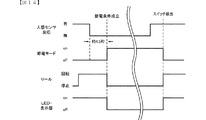
前記可変表示装置(リール2L、2C、2R)の変動表示が開始した後、前記導出制御手段により前記可変表示装置に表示結果が導出されるまでに、前記遊技者検知手段(人感センサ5)により遊技者が検知されなくなった場合に、該可変表示装置(リール2L、2C、2R)の変動表示を一旦停止させることにより変動表示中よりも消費電力を少なくする変動停止手段と、
前記変動停止手段により前記可変表示装置(リール2L、2C、2R)の変動表示が停止している状態で、所定の再開条件(節電モードの解除条件)が成立した場合に、前記可変表示装置(リール2L、2C、2R)の変動表示を再開させる変動再開手段と、
を備える
ことを特徴としている。
この特徴によれば、可変表示装置の変動表示が開始した後、導出制御手段により表示結果が導出されるまでに、遊技者検知手段により遊技者が検知されなくなった場合に、可変表示装置の変動表示が一旦停止され、その後、遊技者が戻って再開条件が成立することで可変表示装置の変動が再開され、遊技者の導出操作によって表示結果を導出させることが可能となる。すなわち、変動停止手段により変動表示が停止した場合には、停止時の表示結果がゲームの結果となるわけではなく、再開条件の成立により変動表示の再開後、遊技者の導出操作によって導出された表示結果がゲームの結果となるため、ゲームの開始後であっても遊技者の不在により効率的に省電力化を図りつつ、遊技者の技術介入を伴うゲームを担保することができる。
尚、可変表示装置の変動表示を一旦停止させることにより変動表示中よりも消費電力を少なくするとは、可変表示装置の駆動を行うモータへの電力供給を停止することや、モータの駆動信号の出力を停止させることで、変動表示中よりも消費電力が少なくなる構成であれば良い。
In order to solve the above-described problem, a slot machine according to
A variable display unit capable of variably displaying a plurality of types of identification information each capable of being identified,
After displaying the variable display unit in a variable manner, the display result is derived by stopping the variable display of the variable display unit, and in a slot machine capable of generating a prize according to the display result,
Game control means for controlling the game and transmitting control information ;
Directing means including light emitting means;
Effect control means for controlling the effect means based on the control information received from the game control means;
Specific detection means provided separately from detection means for detecting a situation related to the progress of the game, and capable of detecting a predetermined situation based on a player who plays the game;
With
The game control means includes
Processing including basic processing means for performing basic processing for executing processes in a predetermined order, and periodic interrupt processing means for performing periodic interrupt processing for interrupting the basic processing and executing processing at regular time intervals Circuit,
A communication circuit including control information storage means capable of storing the control information, and transmitting control information stored in the control information storage means to the effect control means;
An error state control means for controlling to an error state where the progress of the game is disabled when an error is detected;
Including
In the basic processing, a plurality of first control information that makes sense according to the progress of the game is generated, and the control information storage means stores the first control information one by one in the order of transmission,
In the periodic interruption process, the second control information is generated according to an event that occurs regardless of the progress of the game, and the process is stored in the control information storage unit.
The processing circuit starts storing a plurality of first control information in the control information storage means, and performs the periodic interrupt processing in a period until the storage of the plurality of first control information is completed. Further includes a periodic interrupt processing prohibition means for prohibiting execution ,
The production control means includes
It is possible to execute power saving control for turning off the light emitting means when a predetermined time has passed without detection by the specific detection means and when a predetermined time has passed without playing a game,
When control information corresponding to the progress of the game is received during execution of the power saving control, the power saving control is ended, and the rendering means is controlled according to the control information,
When a predetermined time elapses without detection by the specific detection means, or when a predetermined time elapses without playing a game, and in the error state, power saving control is performed until the error state ends. A slot machine that performs power saving control from the time when the error state ends without being executed.
It is characterized by that.
The slot machine of
A game can be started by setting a predetermined number of bets for one game using game values (medals), and a plurality of types of symbols that can be identified by a motor can be displayed in a variable manner. A slot machine (slot) in which one game is completed when a display result is derived to the variable display device (
Fluctuation starting means for starting variable display of the variable display devices (
Derivation control means for controlling the variable display device (
A player detection means (human sensor 5) for detecting a player;
After the variable display on the variable display devices (
In a state where the variable display of the variable display devices (
It is characterized by having.
According to this feature, when the player is no longer detected by the player detection means until the display result is derived by the derivation control means after the variable display of the variable display apparatus is started, The display is temporarily stopped, and then the player returns and the restart condition is satisfied, whereby the change of the variable display device is restarted, and the display result can be derived by the player's derivation operation. That is, when the variable display is stopped by the variable stop means, the display result at the time of the stop is not the game result, but is derived by the player's derivation operation after the variable display is restarted due to the establishment of the restart condition. Since the display result is the result of the game, even after the start of the game, it is possible to secure a game with technical intervention of the player while efficiently saving power due to the absence of the player.
In order to reduce the power consumption by temporarily stopping the variable display of the variable display device than during the variable display, the power supply to the motor that drives the variable display device is stopped or the drive signal of the motor is output. Any configuration that consumes less power than during variable display by stopping the display may be used.
本発明の手段2のスロットマシンは、手段1に記載のスロットマシンであって、
前記変動停止手段は、前記変動表示を一旦停止させる場合に、入賞に対応しない停止態様(入賞ラインにいずれの役も揃わない停止態様)で変動表示を停止させる
ことを特徴としている。
この特徴によれば、変動停止手段により停止した停止態様により遊技者が入賞の発生と誤認してしまうことを防止できる。
The slot machine according to
The variation stop means is characterized in that, when the variation display is temporarily stopped, the variation display is stopped in a stop mode that does not correspond to a winning (stop mode in which no winning line is arranged).
According to this feature, it is possible to prevent the player from misidentifying that a winning has occurred due to the stop mode stopped by the variation stop means.
本発明の手段3のスロットマシンは、手段1または手段2に記載のスロットマシンであって、
前記変動停止手段は、前記変動表示を一旦停止させる場合に、前記導出制御手段により導出され得ない停止態様(基準位置から半コマずれた位置となる停止態様)で変動表示を停止させる
ことを特徴としている。
この特徴によれば、可変表示装置の表示態様から、変動停止手段により停止した停止態様なのか、導出制御手段により導出された停止態様なのか、を判別できる。
The slot machine of
The fluctuation stop means stops the fluctuation display in a stop mode (a stop mode in which the position is shifted by a half frame from a reference position) that cannot be derived by the derivation control unit when the fluctuation display is temporarily stopped. It is said.
According to this feature, it is possible to determine from the display mode of the variable display device whether the stop mode is stopped by the fluctuation stop unit or the stop mode derived by the derivation control unit.
本発明の手段4のスロットマシンは、手段1〜3のいずれかに記載のスロットマシンであって、
前記所定の再開条件(節電モードの解除条件)は、前記遊技者検知手段(人感センサ5)により遊技者が検知され、かつ遊技者による操作(MAXBETスイッチ6、スタートスイッチ7、ストップスイッチ8L、8C、8Rのいずれかの操作)が検知された場合に成立する
ことを特徴としている。
この特徴によれば、遊技者が検知されても、遊技者が操作をして積極的にゲームを再開するという意思表示がなければ変動表示が再開されないため、遊技者が再開する意志がないにも関わらず、変動表示が再開してしまうことを防止できる。
The slot machine of
The predetermined restart condition (condition for canceling the power saving mode) is that the player is detected by the player detecting means (human sensor 5), and the operation by the player (
According to this feature, even if a player is detected, the variable display is not resumed unless there is an intention to restart the game actively by the player's operation, so the player has no intention to resume. Nevertheless, it is possible to prevent the variable display from restarting.
本発明の手段5のスロットマシンは、手段4に記載のスロットマシンであって、
前記遊技者による操作は、遊技を進行させるための遊技操作手段(MAXBETスイッチ6、スタートスイッチ7、ストップスイッチ8L、8C、8R)の操作であり、
前記変動停止手段により前記可変表示装置の変動表示が停止している状態で前記遊技操作手段(ストップスイッチ8L、8C、8R)の操作が検出された場合には、前記所定の再開条件(節電モードの解除条件)が成立しても該遊技操作手段(ストップスイッチ8L、8C、8R)の操作は遊技の進行に関与しない
ことを特徴としている。
この特徴によれば、遊技者が意図せずに、遊技が進行してしまうことを防止できる。
The slot machine according to
The operation by the player is an operation of game operation means (
If an operation of the game operation means (
According to this feature, it is possible to prevent the game from proceeding unintentionally by the player.
本発明の手段6のスロットマシンは、手段1〜手段5のいずれかに記載のスロットマシンであって、
前記遊技者検知手段(人感センサ5)は、遊技を進行させるための遊技操作手段(MAXBETスイッチ6、スタートスイッチ7、ストップスイッチ8L、8C、8R)の周囲の検出状況に基づいて遊技者を検知する
ことを特徴としている。
この特徴によれば、遊技を行っている遊技者の存在を確実に検知することができる。
The slot machine of
The player detection means (human sensor 5) detects the player based on the detection status around the game operation means (
According to this feature, it is possible to reliably detect the presence of a player who is playing a game.
本発明の実施例を以下に説明する。 Examples of the present invention will be described below.
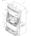
本発明が適用されたスロットマシンの実施例を図面を用いて説明すると、本実施例のスロットマシン1は、前面が開口する筐体1aと、この筐体1aの側端に回動自在に枢支された前面扉1bと、から構成されている。
An embodiment of a slot machine to which the present invention is applied will be described with reference to the drawings. A
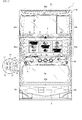
本実施例のスロットマシン1の筐体1aの内部には、図2に示すように、外周に複数種の図柄が配列されたリール2L、2C、2R(以下、左リール、中リール、右リール)が水平方向に並設されており、図1に示すように、これらリール2L、2C、2Rに配列された図柄のうち連続する3つの図柄が前面扉1bに設けられた透視窓3から見えるように配置されている。
Inside the
リール2L、2C、2Rの外周部には、図3に示すように、それぞれ「黒7」、「網7(図中網掛け7)」、「白7」、「BAR」、「リプレイ」、「スイカ」、「チェリー」、「ベル」、「オレンジ」といった互いに識別可能な複数種類の図柄が所定の順序で、それぞれ21個ずつ描かれている。リール2L、2C、2Rの外周部に描かれた図柄は、透視窓3において各々上中下三段に表示される。
As shown in FIG. 3, on the outer periphery of the
各リール2L、2C、2Rは、各々対応して設けられリールモータ32L、32C、32R(図4参照)によって回転させることで、各リール2L、2C、2Rの図柄が透視窓3に連続的に変化しつつ表示されるとともに、各リール2L、2C、2Rの回転を停止させることで、透視窓3に3つの連続する図柄が表示結果として導出表示されるようになっている。
The
リール2L、2C、2Rの内側には、リール2L、2C、2Rそれぞれに対して、基準位置を検出するリールセンサ33L、33C、33Rと、リール2L、2C、2Rを背面から照射するリールLED55と、が設けられている。また、リールLED55は、リール2L、2C、2Rの連続する3つの図柄に対応する12のLEDからなり、各図柄をそれぞれ独立して照射可能とされている。
Inside the
前面扉1bにおける各リール2L,2C,2Rに対応する位置には、リール2L,2C,2Rを前面側から透視可能とする横長長方形状の透視窓3が設けられており、該透視窓3を介して遊技者側から各リール2L,2C,2Rが視認できるようになっている。
At the position corresponding to each
前面扉1bには、メダルを投入可能なメダル投入部4、メダルが払い出されるメダル払出口9、クレジット(遊技者所有の遊技用価値として記憶されているメダル数)を用いて、その範囲内において遊技状態に応じて定められた規定数の賭数のうち最大の賭数(本実施例ではいずれの遊技状態においても3)を設定する際に操作されるMAXBETスイッチ6、クレジットとして記憶されているメダル及び賭数の設定に用いたメダルを精算する(クレジット及び賭数の設定に用いた分のメダルを返却させる)際に操作される精算スイッチ10、ゲームを開始する際に操作されるスタートスイッチ7、リール2L、2C、2Rの回転を各々停止する際に操作されるストップスイッチ8L、8C、8R、演出に用いるための演出用スイッチ56が遊技者により操作可能にそれぞれ設けられている。
The
また、透視窓3の上方には、人感センサ5が設けられている。人感センサ5は、図1の波線で示す感知エリア内の温度変化により人の存在を感知するセンサであり、人の存在を感知した状態か否かを判定し、人の存在を感知していると判定されている間、継続的に感知信号を出力するための判定ユニットを含む。人感センサ5は、その感知エリアが、MAXBETスイッチ6、スタートスイッチ7、ストップスイッチ8L、8C、8R、メダル投入部4及びスロットマシン1前方に位置する遊技者が検出できる位置に配置されている。また、人感センサ5の台座(図視略)には、可変機構が設けられており、手で感知エリアの方向を動かすことにより感知エリアを微調整することが可能とされている。また、後述するセンサ強度切替スイッチ36c(図4参照)の設定によりセンサ強度(感知の強度)を変更可能とされており、設置状況に応じて、例えば、隣の台との干渉を避ける必要がある場合など、人感センサ5のセンサ強度についても調整することが可能とされている。
A
また、前面扉1bには、クレジットとして記憶されているメダル枚数が表示されるクレジット表示器11、入賞の発生により払い出されたメダル枚数やエラー発生時にその内容を示すエラーコード等が表示される遊技補助表示器12、賭数が1設定されている旨を点灯により報知する1BETLED14、賭数が2設定されている旨を点灯により報知する2BETLED15、賭数が3設定されている旨を点灯により報知する3BETLED16、メダルの投入が可能な状態を点灯により報知する投入要求LED17、スタートスイッチ7の操作によるゲームのスタート操作が有効である旨を点灯により報知するスタート有効LED18、ウェイト(前回のゲーム開始から一定期間経過していないためにリールの回転開始を待機している状態)中である旨を点灯により報知するウェイト中LED19、後述するリプレイゲーム中である旨を点灯により報知するリプレイ中LED20が設けられた遊技用表示部13が設けられている。
The
MAXBETスイッチ6の内部には、MAXBETスイッチ6の操作による賭数の設定操作が有効である旨を点灯により報知するBETスイッチ有効LED21(図4参照)が設けられており、ストップスイッチ8L、8C、8Rの内部には、該当するストップスイッチ8L、8C、8Rによるリールの停止操作が有効である旨を点灯により報知する左、中、右停止有効LED22L、22C、22R(図4参照)がそれぞれ設けられている。
Inside the
前面扉1bの内側には、所定のキー操作により後述するエラー状態及び後述する打止状態を解除するためのリセット操作を検出するリセットスイッチ23、後述する設定値の変更中や設定値の確認中にその時点の設定値が表示される設定値表示器24、後述のBB終了時に打止状態(リセット操作がなされるまでゲームの進行が規制される状態)に制御する打止機能の有効/無効を選択するための打止スイッチ36a、後述のBB終了時に自動精算処理(クレジットとして記憶されているメダルを遊技者の操作によらず精算(返却)する処理)に制御する自動精算機能の有効/無効を選択するための自動精算スイッチ36b、人感センサ5のセンサ強度を設定するためのセンサ強度切替スイッチ36c、メダル投入部4から投入されたメダルの流路を、筐体1a内部に設けられた後述のホッパータンク34a(図2参照)側となる取込側通路またはメダル払出口9側となる排出側通路のいずれか一方に選択的に切り替えるための流路切替ソレノイド30、メダル投入部4から投入され、ホッパータンク34a側に流下したメダルを検出する投入メダルセンサ31を有するメダルセレクタ(図示略)、前面扉1bの開放状態を検出するドア開放検出スイッチ25(図4参照)が設けられている。流路切替ソレノイド30は、メダル投入部4から投入されたメダルの流路が、非通電状態では排出側通路であり、通電状態とすることで取込側通路に切り替わり、さらに通電状態から非通電状態とすることで排出側通路に戻るようになっている。
Inside the
筐体1a内部には、図2に示すように、前述したリール2L、2C、2R、リールモータ32L、32C、32R、各リール2L、2C、2Rのリール基準位置をそれぞれ検出可能なリールセンサ33L、33C、33R(図4参照)からなるリールユニット2、外部出力信号を出力するための外部出力基板1000、メダル投入部4から投入されたメダルを貯留するホッパータンク34a、ホッパータンク34aに貯留されたメダルをメダル払出口9より払い出すためのホッパーモータ34b、ホッパーモータ34bの駆動により払い出されたメダルを検出する払出センサ34cからなるホッパーユニット34、電源ボックス100が設けられている。
As shown in FIG. 2, a reel sensor 33L that can detect the reel reference positions of the
ホッパーユニット34の側部には、ホッパータンク34aから溢れたメダルが貯留されるオーバーフロータンク35が設けられている。オーバーフロータンク35の内部には、貯留された所定量のメダルを検出可能な高さに設けられた左右に離間する一対の導電部材からなる満タンセンサ35aが設けられており、導電部材がオーバーフロータンク35内に貯留されたメダルを介して接触することにより導電したときに内部に貯留されたメダル貯留量が所定量以上となったこと、すなわちオーバーフロータンクが満タン状態となったことを検出できるようになっている。
On the side of the
電源ボックス100の前面には、設定変更状態または設定確認状態に切り替えるための設定キースイッチ37、通常時においてはエラー状態や打止状態を解除するためのリセットスイッチとして機能し、設定変更状態においては後述する内部抽選の当選確率(出玉率)の設定値を変更するための設定スイッチとして機能するリセット/設定スイッチ38、電源をon/offする際に操作される電源スイッチ39が設けられている。
The front side of the
本実施例のスロットマシン1においてゲームを行う場合には、まず、メダルをメダル投入部4から投入するか、あるいはクレジットを使用して賭数を設定する。クレジットを使用するにはMAXBETスイッチ6を操作すれば良い。遊技状態に応じて定められた規定数の賭数が設定されると、入賞ラインL1〜L5(図1参照)が有効となり、スタートスイッチ7の操作が有効な状態、すなわち、ゲームが開始可能な状態となる。本実施例では、規定数の賭数として遊技状態に関わらず3枚が定められて規定数の賭数が設定されると入賞ラインL1〜L5が有効となる。尚、遊技状態に対応する規定数のうち最大数を超えてメダルが投入された場合には、その分はクレジットに加算される。
When a game is played in the
入賞ラインとは、各リール2L、2C、2Rの透視窓3に表示された図柄の組み合わせが入賞図柄の組み合わせであるかを判定するために設定されるラインである。本実施例では、図1に示すように、各リール2L、2C、2Rの中段に並んだ図柄に跨って設定された入賞ラインL1、各リール2L、2C、2Rの上段に並んだ図柄に跨って設定された入賞ラインL2、各リール2L、2C、2Rの下段に並んだ図柄に跨って設定された入賞ラインL3、リール2Lの上段、リール2Cの中段、リール2Rの下段、すなわち右下がりに並んだ図柄に跨って設定された入賞ラインL4、リール2Lの下段、リール2Cの中段、リール2Rの上段、すなわち右上がりに並んだ図柄に跨って設定された入賞ラインL5の5種類が入賞ラインとして定められている。
The winning line is a line that is set to determine whether a combination of symbols displayed on the
ゲームが開始可能な状態でスタートスイッチ7を操作すると、各リール2L、2C、2Rが回転し、各リール2L、2C、2Rの図柄が連続的に変動する。この状態でいずれかのストップスイッチ8L、8C、8Rを操作すると、対応するリール2L、2C、2Rの回転が停止し、透視窓3に表示結果が導出表示される。
When the
そして全てのリール2L、2C、2Rが停止されることで1ゲームが終了し、有効化され入賞ライン上に予め定められた図柄の組み合わせ(以下、役とも呼ぶ)が各リール2L、2C、2Rの表示結果として停止した場合には入賞が発生し、その入賞に応じて定められた枚数のメダルが遊技者に対して付与され、クレジットに加算される。また、クレジットが上限数(本実施例では50)に達した場合には、メダルが直接メダル払出口9(図1参照)から払い出されるようになっている。尚、有効化され複数の入賞ライン上にメダルの払出を伴う図柄の組み合わせが揃った場合には、有効化され入賞ラインに揃った図柄の組み合わせそれぞれに対して定められた払出枚数を合計し、合計した枚数のメダルが遊技者に対して付与されることとなる。ただし、1ゲームで付与されるメダルの払出枚数には、上限(本実施例では15枚)が定められており、合計した払出枚数が上限を超える場合には、上限枚数のメダルが付与されることとなる。また、有効化され入賞ライン上に、遊技状態の移行を伴う図柄の組み合わせが各リール2L、2C、2Rの表示結果として停止した場合には図柄の組み合わせに応じた遊技状態に移行するようになっている。
Then, when all the
また、本実施例におけるスロットマシン1にあっては、ゲームが開始されて各リール2L、2C、2Rが回転して図柄の変動が開始した後、いずれかのストップスイッチ8L、8C、8Rが操作されたときに、当該ストップスイッチ8L、8C、8Rに対応するリールの回転が停止して図柄が停止表示される。ストップスイッチ8L、8C、8Rの操作から対応するリール2L、2C、2Rの回転を停止するまでの最大停止遅延時間は190ms(ミリ秒)である。
In the
リール2L、2C、2Rは、1分間に80回転し、80×21(1リール当たりの図柄コマ数)=1680コマ分の図柄を変動させるので、190msの間では最大で4コマの図柄を引き込むことができることとなる。つまり、停止図柄として選択可能なのは、ストップスイッチ8L、8C、8Rが操作されたときに表示されている図柄と、そこから4コマ先までにある図柄、合計5コマ分の図柄である。
The
このため、例えば、ストップスイッチ8L、8C、8Rのいずれかが操作されたときに当該ストップスイッチに対応するリールの下段に表示されている図柄を基準とした場合、当該図柄から4コマ先までの図柄を下段に表示させることができるため、リール2L、2C、2R各々において、ストップスイッチ8L、8Rのうちいずれかが操作されたときに当該ストップスイッチに対応するリールの中段に表示されている図柄を含めて5コマ以内に配置されている図柄を入賞ライン上に表示させることができる。
For this reason, for example, when any one of the stop switches 8L, 8C, 8R is operated and the symbol displayed on the lower stage of the reel corresponding to the stop switch is used as a reference, the symbol from the symbol to four frames ahead is used. Since the symbols can be displayed in the lower row, in each of the
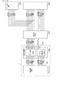
図4は、スロットマシン1の構成を示すブロック図である。スロットマシン1には、図4に示すように、遊技制御基板40、演出制御基板90、電源基板101が設けられており、遊技制御基板40によって遊技状態が制御され、演出制御基板90によって遊技状態に応じた演出が制御され、電源基板101によってスロットマシン1を構成する電気部品の駆動電源が生成され、各部に供給される。
FIG. 4 is a block diagram showing a configuration of the
電源基板101には、外部からAC100Vの電源が供給されるとともに、このAC100Vの電源からスロットマシン1を構成する電気部品の駆動に必要な直流電圧が生成され、遊技制御基板40及び遊技制御基板40を介して接続された演出制御基板90に供給されるようになっている。また、後述するメイン制御部41からサブ制御部91へのコマンド伝送ラインと、遊技制御基板40から演出制御基板90に対して電源を供給する電源供給ラインと、が一系統のケーブル及びコネクタを介して接続されており、これらケーブルと各基板とを接続するコネクタ同士が全て接続されることで演出制御基板90側の各部が動作可能となり、かつメイン制御部41からのコマンドを受信可能な状態となる。このため、メイン制御部41からコマンドを伝送するコマンド伝送ラインが演出制御基板90に接続されている状態でなければ、演出制御基板90側に電源が供給されず、演出制御基板90側のみが動作してしまうことがない。
The
また、電源基板101には、前述したホッパーモータ34b、払出センサ34c、満タンセンサ35a、設定キースイッチ37、リセット/設定スイッチ38、電源スイッチ39が接続されている。
Further, the above-described
遊技制御基板40には、前述したMAXBETスイッチ6、スタートスイッチ7、ストップスイッチ8L、8C、8R、精算スイッチ10、リセットスイッチ23、打止スイッチ36a、自動精算スイッチ36b、人感センサ5、投入メダルセンサ31、ドア開放検出スイッチ25、リールセンサ33L、33C、33Rが接続されているとともに、電源基板101を介して前述した払出センサ34c、満タンセンサ35a、設定キースイッチ37、リセット/設定スイッチ38が接続されており、これら接続されたスイッチ類の検出信号が入力されるようになっている。尚、センサ強度切替スイッチ36cは、前述した人感センサ5の判定ユニットに接続されており、この判定ユニットにより強度切替スイッチ36の設定状態が検知され、センサ強度が設定されるようになっている。
On the
また、遊技制御基板40には、前述したクレジット表示器11、遊技補助表示器12、ペイアウト表示器13、1〜3BETLED14〜16、投入要求LED17、スタート有効LED18、ウェイト中LED19、リプレイ中LED20、BETスイッチ有効LED21、左、中、右停止有効LED22L、22C、22R、設定値表示器24、流路切替ソレノイド30、リールモータ32L、32C、32Rが接続されているとともに、電源基板101を介して前述したホッパーモータ34bが接続されており、これら電気部品は、遊技制御基板40に搭載された後述のメイン制御部41の制御に基づいて駆動されるようになっている。
Further, the
遊技制御基板40には、メイン制御部41、制御用クロック生成回路42、乱数用クロック生成回路43、スイッチ検出回路44、モータ駆動回路45、ソレノイド駆動回路46、LED駆動回路47、電断検出回路48、リセット回路49が搭載されている。
The
メイン制御部41は、1チップマイクロコンピュータにて構成され、後述するROM506に記憶された制御プログラムを実行して、遊技の進行に関する処理を行うととともに、遊技制御基板40に搭載された制御回路の各部を直接的または間接的に制御する。
The
制御用クロック生成回路42は、メイン制御部41の外部にて、所定周波数の発振信号となる制御用クロックCCLKを生成する。制御用クロック生成回路42により生成された制御用クロックCCLKは、例えば図5(A)に示すようなメイン制御部41の制御用外部クロック端子EXCを介してクロック回路502に供給される。乱数用クロック生成回路43は、メイン制御部41の外部にて、制御用クロックCCLKの発振周波数とは異なる所定周波数の発振信号となる乱数用クロックRCLKを生成する。乱数用クロック生成回路43により生成された乱数用クロックRCLKは、例えば図5(A)に示すようなメイン制御部41の乱数用外部クロック端子ERCを介して乱数回路509に供給される。一例として、乱数用クロック生成回路43により生成される乱数用クロックRCLKの発振周波数は、制御用クロック生成回路42により生成される制御用クロックCCLKの発振周波数以下となるようにすれば良い。
The control
スイッチ検出回路44は、遊技制御基板40に直接または電源基板101を介して接続されたスイッチ類から入力された検出信号を取り込んでメイン制御部41に伝送する。モータ駆動回路45は、メイン制御部41から出力されたモータ駆動信号をリールモータ32L、32C、32Rに伝送する。ソレノイド駆動回路46は、メイン制御部41から出力されたソレノイド駆動信号を流路切替ソレノイド30に伝送する。LED駆動回路は、メイン制御部41から出力されたLED駆動信号を遊技制御基板40に接続された各種表示器やLEDに伝送する。電断検出回路48は、スロットマシン1に供給される電源電圧を監視し、電圧低下を検出したときに、その旨を示す電圧低下信号をメイン制御部41に対して出力する。リセット回路49は、電源投入時または電源遮断時などの電源が不安定な状態においてメイン制御部41にシステムリセット信号を与える。また、リセット回路49は、ウォッチドッグタイマ49a(図5(B)参照)を内蔵し、ウォッチドッグタイマ49aがタイムアップした場合、すなわちメイン制御部41のCPU505の動作が一定時間停止した場合においてメイン制御部41にユーザリセット信号を与える。
The
図5(A)は、遊技制御基板40に搭載されたメイン制御部41の構成例を示している。図5(A)に示すメイン制御部41は、1チップマイクロコンピュータであり、外部バスインタフェース501と、クロック回路502と、固有情報記憶回路503と、リセット/割込コントローラ504と、CPU505と、ROM506と、RAM507と、CTC(カウンタ/タイマサーキット)508と、乱数回路509と、PIP(パラレルインプットポート)510と、シリアル通信回路511と、アドレスデコード回路512とを備えて構成される。
FIG. 5A shows a configuration example of the
図5(A)に示すメイン制御部41が備える外部バスインタフェース501は、メイン制御部41を構成するチップの外部バスと内部バスとのインタフェース機能や、アドレスバス、データバス及び各制御信号の方向制御機能などを有するバスインタフェースである。例えば、外部バスインタフェース501は、メイン制御部41に外付けされた外部メモリや外部入出力装置などに接続され、これらの外部装置との間でアドレス信号やデータ信号、各種の制御信号などを送受信するものであれば良い。この実施の形態において、外部バスインタフェース501には、内部リソースアクセス制御回路501Aが含まれている。
The external bus interface 501 provided in the
内部リソースアクセス制御回路501Aは、外部バスインタフェース501を介した外部装置からメイン制御部41の内部データに対するアクセスを制御して、例えばROM506に記憶されたゲーム制御用プログラムや固定データといった、内部データの不適切な外部読出を制限するための回路である。ここで、外部バスインタフェース501には、例えばインサーキットエミュレータ(ICE)といった回路解析装置が、外部装置として接続されることがある。
The internal resource access control circuit 501A controls access to internal data of the
メイン制御部41が備えるクロック回路502は、例えば制御用外部クロック端子EXCに入力される発振信号を2分周することなどにより、内部システムクロックSCLKを生成する回路である。本実施例では、制御用外部クロック端子EXCに制御用クロック生成回路42が生成した制御用クロックCCLKが入力される。クロック回路502により生成された内部システムクロックSCLKは、例えばCPU505といった、メイン制御部41において遊技の進行を制御する各種回路に供給される。また、内部システムクロックSCLKは、乱数回路509にも供給され、乱数用クロック生成回路43から供給される乱数用クロックRCLKの周波数を監視するために用いられる。さらに、内部システムクロックSCLKは、クロック回路502に接続されたシステムクロック出力端子CLKOから、メイン制御部41の外部へと出力されても良い。尚、内部システムクロックSCLKは、メイン制御部41の外部へは出力されないことが望ましい。このように、内部システムクロックSCLKの外部出力を制限することにより、メイン制御部41の内部回路(CPU505など)の動作周期を外部から特定することが困難になり、乱数値となる数値データをソフトウェアにより更新する場合に、乱数値の更新周期が外部から特定されてしまうことを防止できる。
The clock circuit 502 provided in the
メイン制御部41が備える固有情報記憶回路503は、例えばメイン制御部41の内部情報となる複数種類の固有情報を記憶する回路である。一例として、固有情報記憶回路503は、ROMコード、チップ個別ナンバー、IDナンバーといった3種類の固有情報を記憶する。ROM506コードは、ROM506の所定領域における記憶データから生成される4バイトの数値であり、生成方法の異なる4つの数値が準備されれば良い。チップ個別ナンバーは、メイン制御部41の製造時に付与される4バイトの番号であり、メイン制御部41を構成するチップ毎に異なる数値を示している。IDナンバーは、メイン制御部41の製造時に付与される8バイトの番号であり、メイン制御部41を構成するチップ毎に異なる数値を示している。ここで、チップ個別ナンバーはユーザプログラムから読み取ることができる一方、IDナンバーはユーザプログラムから読み取ることができないように設定されていれば良い。尚、固有情報記憶回路503は、例えばROM506の所定領域を用いることなどにより、ROM506に含まれるようにしても良い。或いは、固有情報記憶回路503は、例えばCPU505の内蔵レジスタを用いることなどにより、CPU505に含まれるようにしても良い。
The unique information storage circuit 503 included in the
メイン制御部41が備えるリセット/割込コントローラ504は、メイン制御部41の内部や外部にて発生する各種リセット、割込要求を制御するためのものである。リセット/割込コントローラ504が制御するリセットには、システムリセットとユーザリセットが含まれている。システムリセットは、外部システムリセット端子XSRSTに一定の期間にわたりローレベル信号(システムリセット信号)が入力されたときに発生するリセットである。ユーザリセットは、外部ユーザリセット端子XURSTに一定の期間にわたりローレベルの信号(ユーザリセット信号)が入力されたとき、または内蔵ウォッチドッグタイマ(WDT)のタイムアウト信号が発生したことや、指定エリア外走行禁止(IAT)が発生したことなど、所定の要因により発生するリセットである。尚、本実施例では前述のように内蔵ウォッチドッグタイマを使用せずにリセット回路49に搭載されたウォッチドッグタイマ(WDT)を用いているため、外部ユーザリセット端子XURSTにユーザリセット信号が入力されるか、指定エリア外走行禁止(IAT)が発生することでユーザリセットが発生することとなる。
The reset / interrupt controller 504 provided in the
本実施例では、図5(B)に示すように、ウォッチドッグタイマ49aを内蔵するリセット回路49を遊技制御基板40に搭載している。リセット回路49は、スロットマシン1への供給電源が安定電圧となり一定時間が経過するまでシステムリセット信号をメイン制御部41に対して出力する。また、ウォッチドッグタイマ49aがタイムアウトした場合には、ユーザリセット信号をメイン制御部41に対して出力する。
In this embodiment, as shown in FIG. 5B, a
図5(B)に示すように、遊技制御基板40では、LED駆動回路47からクレジット表示器11へ接続される信号線のうち、クレジット表示器11を構成する複数のセグメントの駆動信号のうち下1桁Bセグメント信号、下1桁Cセグメント信号、上1桁Bセグメント信号、上1桁Cセグメント信号の信号線が分岐し、or回路を介してリセット回路49のウォッチドッグタイマクリア信号端子に接続されている。
As shown in FIG. 5 (B), in the
本実施例では、メイン制御部41が、クレジット表示器11の下1桁Bセグメント、下1桁Cセグメント、上1桁Bセグメント、上1桁Cセグメントのいずれかのセグメントを必ずダイナミック点灯させる制御を行っており、これらのセグメントをダイナミック点灯させるため、メイン制御部41が正常に動作していれば、これら4つのセグメントのいずれかの駆動信号が定期的に出力されるはずであり、これら4つのセグメントのいずれかの駆動信号が定期的に出力されているか否かを監視することにより、メイン制御部41が正常に動作しているか否かを判定することが可能となる。
In the present embodiment, the
そして、これら4つのセグメントの駆動信号をor回路を介して1つにまとめた信号がリセット回路49のウォッチドッグタイマクリア信号端子に入力され、ウォッチドッグタイマ49aがクリアされるようになっており、上記4つのセグメントの駆動信号の出力が停止して、ウォッチドッグタイマ49aがクリアされず、タイムアップすることで、ユーザリセット信号がメイン制御部41に対して出力されるようになっている。
A signal obtained by combining the drive signals of these four segments into one via the or circuit is input to the watchdog timer clear signal terminal of the
このように本実施例では、定期的に駆動信号が与えられるLEDのセグメント信号を分岐してウォッチドッグタイマ49aをクリアするようになっており、メイン制御部41のCPU505が個別にウォッチドッグタイマ49aをクリアする処理を行うことなく、メイン制御部41が正常に動作しているか否かを監視することが可能となることから好ましいが、メイン制御部41からリセット回路49のウォッチドッグタイマクリア信号端子に個別のクリア信号を入力することでウォッチドッグタイマ49aをクリアするようにしても良い。
As described above, in this embodiment, the segment signal of the LED to which the drive signal is given periodically is branched to clear the watchdog timer 49a, and the CPU 505 of the
また、本実施例では、メイン制御部41の外部に設けられたリセット回路49にウォッチドッグタイマ49aを搭載する構成であるが、メイン制御部41に内蔵されたウォッチドッグタイマを用いてメイン制御部41の動作を監視するようにしても良い。
In the present embodiment, the watchdog timer 49a is mounted on the
リセット/割込コントローラ504が制御する割込には、ノンマスカブル割込NMIとマスカブル割込INTが含まれている。ノンマスカブル割込NMIは、CPU505の割込禁止状態でも無条件に受け付けられる割込であり、外部ノンマスカブル割込端子XNMI(入力ポートP4と兼用)に一定の期間にわたりローレベル信号が入力されたときに発生する割込である。マスカブル割込INTは、CPU505の設定命令により、割込要求の受け付けを許可/禁止できる割込であり、優先順位設定による多重割込の実行が可能である。マスカブル割込INTの要因としては、外部マスカブル割込端子XINT(入力ポートP3と兼用)に一定の期間にわたりローレベル信号が入力されたこと、CTC508に含まれるタイマ回路にてタイムアウトが発生したこと、シリアル通信回路511にてデータ送信による割込要因が発生したこと、乱数回路509にて乱数値となる数値データの取り込みによる割込要因が発生したことなど、複数種類の割込要因が予め定められていれば良い。 Interrupts controlled by the reset / interrupt controller 504 include a non-maskable interrupt NMI and a maskable interrupt INT. The non-maskable interrupt NMI is an interrupt that is unconditionally accepted even when the CPU 505 is in an interrupt-disabled state. An interrupt that occurs. The maskable interrupt INT is an interrupt that can permit / prohibit acceptance of an interrupt request by a setting instruction of the CPU 505, and multiple interrupts can be executed by setting priority. The maskable interrupt INT is caused by the fact that a low level signal is input to the external maskable interrupt terminal XINT (also used as the input port P3) for a certain period of time, a time-out occurs in the timer circuit included in the CTC 508, Multiple types of interrupt factors are determined in advance, such as the occurrence of an interrupt factor due to data transmission in the serial communication circuit 511 and the occurrence of an interrupt factor due to the acquisition of numerical data as a random value in the random number circuit 509. It should be.
メイン制御部41が備えるCPU505は、ROM506から読み出したプログラムを実行することにより、スロットマシン1におけるゲームの進行を制御するための処理などを実行する。このときには、CPU505がROM506から固定データを読み出す固定データ読出動作や、CPU505がRAM507に各種の変動データを書き込んで一時記憶させる変動データ書込動作、CPU505がRAM507に一時記憶されている各種の変動データを読み出す変動データ読出動作、CPU505が外部バスインタフェース501やPIP510などを介してメイン制御部41の外部から各種信号の入力を受け付ける受信動作、CPU505が外部バスインタフェース501やシリアル通信回路511などを介してメイン制御部41の外部へと各種信号を出力する送信動作等も行われる。
The CPU 505 provided in the
このように、メイン制御部41では、CPU505がROM506に格納されているプログラムに従って制御を実行するので、以下、メイン制御部41(又はCPU505)が実行する(又は処理を行う)ということは、具体的には、CPU505がプログラムに従って制御を実行することである。このことは、遊技制御基板40以外の他の基板に搭載されているマイクロコンピュータについても同様である。
As described above, in the
メイン制御部41が備えるROM506には、ゲーム制御用のユーザプログラムや固定データ等が記憶されている。また、ROM506には、セキュリティチェックプログラム506Aが記憶されている。CPU505は、スロットマシン1の電源投入やシステムリセットの発生に応じてメイン制御部41がセキュリティモードに移行したときに、ROM506に記憶されたセキュリティチェックプログラム506Aを読み出し、ROM506の記憶内容が変更されたか否かを検査するセキュリティチェック処理を実行する。尚、セキュリティチェックプログラム506Aは、ROM506とは異なる内蔵メモリに記憶されても良い。また、セキュリティチェックプログラム506Aは、例えば外部バスインタフェース501を介してメイン制御部41に外付けされた外部メモリの記憶内容を検査するセキュリティチェック処理に対応したものであっても良い。
A ROM 506 provided in the
メイン制御部41が備えるRAM507は、ゲーム制御用のワークエリアを提供する。ここで、RAM507の少なくとも一部は、バックアップ電源によってバックアップされているバックアップRAMであれば良い。すなわち、スロットマシンへの電力供給が停止しても、所定期間はRAM507の少なくとも一部の内容が保存される。尚、本実施例では、RAM507の全ての領域がバックアップRAMとされており、スロットマシンへの電力供給が停止しても、所定期間はRAM507の全ての内容が保存される。
A RAM 507 provided in the
メイン制御部41が備えるCTC508は、例えば8ビットのプログラマブルタイマを3チャネル(PTC0−PTC2)内蔵して構成され、リアルタイム割込の発生や時間計測を可能とするタイマ回路を含んでいる。各プログラマブルタイマPTC0−PTC2は、内部システムクロックSCLKに基づいて生成されたカウントクロックの信号変化(例えばハイレベルからローレベルへと変化する立ち下がりタイミング)などに応じて、タイマ値が更新されるものであれば良い。また、CTC508は、例えば8ビットのプログラマブルカウンタを4チャネル(PCC0−PCC3)内蔵しても良い。各プログラマブルカウンタPCC0−PCC3は、内部システムクロックSCLKの信号変化、或いは、プログラマブルカウンタPCC0−PCC3のいずれかにおけるタイムアウトの発生などに応じて、カウント値が更新されるものであれば良い。CTC508は、セキュリティ時間を延長する際の延長時間(可変設定時間)をシステムリセット毎にランダムに決定するために用いられるフリーランカウンタや、乱数回路509にて生成される乱数のスタート値をシステムリセット毎にランダムに決定するために用いられるフリーランカウンタなどを、含んでも良い。或いは、これらのフリーランカウンタは、例えばRAM507のバックアップ領域といった、CTC508とは異なるメイン制御部41の内部回路に含まれても良い。
The CTC 508 provided in the
メイン制御部41が備える乱数回路509は、例えば16ビット乱数といった、所定の更新範囲を有する乱数値となる数値データを生成する回路である。本実施例では、遊技制御基板40の側において、後述する内部抽選用の乱数値を示す数値データがカウント可能に制御される。尚、遊技効果を高めるために、これら以外の乱数値が用いられても良い。CPU505は、乱数回路509から抽出した数値データに基づき、乱数回路509とは異なるランダムカウンタを用いて、ソフトウェアによって各種の数値データを加工或いは更新することで、内部抽選用の乱数値を示す数値データをカウントするようにしても良い。以下では、内部抽選用の乱数値を示す数値データが、ハードウェアとなる乱数回路509からCPU505により抽出された数値データをソフトウェアにより加工しないものとする。尚、乱数回路509は、メイン制御部41に内蔵されるものであっても良いし、メイン制御部41とは異なる乱数回路チップとして、メイン制御部41に外付けされるものであっても良い。
A random number circuit 509 included in the
内部抽選用の乱数値は、複数種類の入賞について発生を許容するか否かを判定するために用いられる値であり、本実施例では、「0」〜「65535」の範囲の値をとる。 The random number for internal lottery is a value used to determine whether or not to allow a plurality of types of winnings, and takes a value in the range of “0” to “65535” in this embodiment.
メイン制御部41が備えるPIP510は、例えば6ビット幅の入力専用ポートであり、専用端子となる入力ポートP0〜入力ポートP2と、機能兼用端子となる入力ポートP3〜入力ポートP5とを含んでいる。入力ポートP3は、CPU505等に接続される外部マスカブル割込端子XINTと兼用される。入力ポートP4は、CPU505等に接続される外部ノンマスカブル割込端子XNMIと兼用される。入力ポートP5は、シリアル通信回路511が使用する第1チャネル受信端子RXAと兼用される。入力ポートP3〜入力ポートP5の使用設定は、プログラム管理エリアに記憶される機能設定KFCSにより指示される。
The PIP 510 included in the
図5に示すメイン制御部41が備えるアドレスデコード回路512は、メイン制御部41の内部における各機能ブロックのデコードや、外部装置用のデコード信号であるチップセレクト信号のデコードを行うための回路である。チップセレクト信号により、メイン制御部41の内部回路、或いは、周辺デバイスとなる外部装置を、選択的に有効動作させて、CPU505からのアクセスが可能となる。
An address decoding circuit 512 provided in the
メイン制御部41が備えるROM506には、ゲーム制御用のユーザプログラムやセキュリティチェックプログラム506Aの他に、ゲームの進行を制御するために用いられる各種の選択用データ、テーブルデータなどが格納される。例えば、ROM506には、CPU505が各種の判定や決定、設定を行うために用意された複数の判定テーブルや決定テーブル、設定テーブルなどを構成するデータが記憶されている。また、ROM506には、CPU505が遊技制御基板40から各種の制御コマンドとなる制御信号を送信するために用いられる複数のコマンドテーブルを構成するテーブルデータなどが記憶されている。
The ROM 506 provided in the
メイン制御部41が備えるRAM507には、スロットマシン1におけるゲームの進行などを制御するために用いられる各種のデータを保持する領域として、遊技制御用データ保持エリア590が設けられている。RAM507としては、例えばDRAMが使用されており、記憶しているデータ内容を維持するためのリフレッシュ動作が必要になる。CPU505には、このリフレッシュ動作を行うためのリフレッシュレジスタが内蔵されている。例えば、リフレッシュレジスタは8ビットからなり、そのうち下位7ビットはCPU505がROM506から命令フェッチするごとに自動的にインクリメントされる。したがって、リフレッシュレジスタにおける格納値の更新は、CPU505における1命令の実行時間ごとに行われることになる。
The RAM 507 provided in the
メイン制御部41は、シリアル通信回路511を介してサブ制御部91に各種のコマンドを送信する。メイン制御部41からサブ制御部91へ送信されるコマンドは一方向のみで送られ、サブ制御部91からメイン制御部41へ向けてコマンドが送られることはない。
The
メイン制御部41は、遊技制御基板40に接続された各種スイッチ類の検出状態が入力ポートから入力される。そしてメイン制御部41は、これら入力ポートから入力される各種スイッチ類の検出状態に応じて段階的に移行する基本処理を実行する。
The
また、メイン制御部41は、割込の発生により基本処理に割り込んで割込処理を実行できるようになっている。本実施例では、CTC508に含まれるタイマ回路にてタイムアウトが発生したこと、すなわち一定時間間隔(本実施例では、約0.56ms)毎に後述するタイマ割込処理(メイン)を実行する。
Further, the
また、メイン制御部41は、割込処理の実行中に他の割込を禁止しないように設定されているとともに、複数の割込が同時に発生した場合には、予め定められた順位によって優先して実行する割込が設定されている。尚、本実施例のメイン制御部41が使用する割込は、CTC508に含まれるタイマ回路にてタイムアウトが発生する毎に発生する1種類の割込のみであり、複数の割込が同時に発生することはない。
In addition, the
メイン制御部41は、基本処理として遊技制御基板40に接続された各種スイッチ類の検出状態が変化するまでは制御状態に応じた処理を繰り返しループし、各種スイッチ類の検出状態の変化に応じて段階的に移行する処理を実行する。また、メイン制御部41は、一定時間間隔(本実施例では、約0.56ms)毎にタイマ割込処理(メイン)を実行する。尚、タイマ割込処理(メイン)の実行間隔は、基本処理において制御状態に応じて繰り返す処理が一巡する時間とタイマ割込処理(メイン)の実行時間とを合わせた時間よりも長い時間に設定されており、今回と次回のタイマ割込処理(メイン)との間で必ず制御状態に応じて繰り返す処理が最低でも一巡することとなる。尚、例外として、後述する節電準備中及び節電モード中は、基本処理に戻らずにそのまま待機するようになっており、次回、CTC508に含まれるタイマ回路にてタイムアウトが発生することで、再びタイマ割込処理(メイン)が先頭から実行されることとなる。
The
メインCPU41aは、I/Oポート41dを介して演出制御基板90に、各種のコマンドを送信する。遊技制御基板40から演出制御基板90へ送信されるコマンドは一方向のみで送られ、演出制御基板90から遊技制御基板40へ向けてコマンドが送られることはない。遊技制御基板40から演出制御基板90へ送信されるコマンドの伝送ラインは、ストローブ(INT)信号ライン、データ伝送ライン、グラウンドラインから構成されている。
The main CPU 41a transmits various commands to the
演出制御基板90には、演出用スイッチ56が接続されており、この演出用スイッチ56の検出信号が入力されるようになっている。
An
また、演出制御基板90には、スロットマシン1の前面扉1bに配置された液晶表示器51(図1参照)、演出効果LED52、スピーカ53、54(図16参照)、前述したリールLED55等の演出装置が接続されており、これら演出装置は、演出制御基板90に搭載された後述のサブ制御部91による制御に基づいて駆動されるようになっている。
The
尚、本実施例では、演出制御基板90に搭載されたサブ制御部91により、液晶表示器51、演出効果LED52、スピーカ53、54、リールLED55等の演出装置の出力制御が行われる構成であるが、サブ制御部91とは別に演出装置の出力制御を直接的に行う出力制御部を演出制御基板90または他の基板に搭載し、サブ制御部91がメイン制御部41からのコマンドに基づいて演出装置の出力パターンを決定し、サブ制御部91が決定した出力パターンに基づいて出力制御部が演出装置の出力制御を行う構成としても良く、このような構成では、サブ制御部91及び出力制御部の双方によって演出装置の出力制御が行われることとなる。
In this embodiment, the
また、本実施例では、演出装置として液晶表示器51、演出効果LED52、スピーカ53、54、リールLED55を例示しているが、演出装置は、これらに限られず、例えば、機械的に駆動する表示装置や機械的に駆動する役モノなどを演出装置として適用しても良い。
Further, in the present embodiment, the
演出制御基板90には、メイン制御部41と同様にサブCPU91a、ROM91b、RAM91c、I/Oポート91dを備えたマイクロコンピュータにて構成され、演出の制御を行うサブ制御部91、演出制御基板90に接続された液晶表示器51の表示制御を行う表示制御回路92、演出効果LED52、リールLED55の駆動制御を行うLED駆動回路93、スピーカ53、54からの音声出力制御を行う音声出力回路94、電源投入時またはサブCPU91aからの初期化命令が一定時間入力されないときにサブCPU91aにリセット信号を与えるリセット回路95、演出制御基板90に接続された演出用スイッチ56から入力された検出信号を検出するスイッチ検出回路96、日付情報及び時刻情報を含む時間情報を出力する時計装置97、スロットマシン1に供給される電源電圧を監視し、電圧低下を検出したときに、その旨を示す電圧低下信号をサブCPU91aに対して出力する電断検出回路98、その他の回路等、が搭載されており、サブCPU91aは、遊技制御基板40から送信されるコマンドを受けて、演出を行うための各種の制御を行うとともに、演出制御基板90に搭載された制御回路の各部を直接的または間接的に制御する。
Similar to the
リセット回路95は、遊技制御基板40においてメイン制御部41にシステムリセット信号を与えるリセット回路49よりもリセット信号を解除する電圧が低く定められており、電源投入時においてサブ制御部91は、メイン制御部41よりも早い段階で起動するようになっている。一方で、電断検出回路98は、遊技制御基板40においてメイン制御部41に電圧低下信号を出力する電断検出回路48よりも電圧低下信号を出力する電圧が低く定められており、電断時においてサブ制御部91は、メイン制御部41よりも遅い段階で停電を検知し、後述する電断処理(サブ)を行うこととなる。
The
サブ制御部91は、メイン制御部41と同様に、割込機能を備えており、メイン制御部41からのコマンド受信時に割込を発生させて、メイン制御部41から送信されたコマンドを取得し、バッファに格納するコマンド受信割込処理を実行する。また、サブ制御部91は、システムクロックの入力数が一定数に到達する毎、すなわち一定間隔毎に割込を発生させて後述するタイマ割込処理(サブ)を実行する。
Similar to the
また、サブ制御部91は、メイン制御部41とは異なり、コマンドの受信に基づいて割込が発生した場合には、タイマ割込処理(サブ)の実行中であっても、当該処理に割り込んでコマンド受信割込処理を実行し、タイマ割込処理(サブ)の契機となる割込が同時に発生してもコマンド受信割込処理を最優先で実行するようになっている。
Also, unlike the
また、サブ制御部91にも、停電時においてバックアップ電源が供給されており、バックアップ電源が供給されている間は、RAM91cに記憶されているデータが保持されるようになっている。
The
本実施例のスロットマシン1は、設定値に応じてメダルの払出率が変わるものである。詳しくは、後述する内部抽選において設定値に応じた当選確率を用いることにより、メダルの払出率が変わるようになっている。設定値は1〜6の6段階からなり、6が最も払出率が高く、5、4、3、2、1の順に値が小さくなるほど払出率が低くなる。すなわち設定値として6が設定されている場合には、遊技者にとって最も有利度が高く、5、4、3、2、1の順に値が小さくなるほど有利度が段階的に低くなる。
In the
設定値を変更するためには、設定キースイッチ37をon状態としてからスロットマシン1の電源をonする必要がある。設定キースイッチ37をon状態として電源をonすると、設定値表示器24にRAM507から読み出された設定値が表示値として表示され、リセット/設定スイッチ38の操作による設定値の変更操作が可能な設定変更状態に移行する。設定変更状態において、リセット/設定スイッチ38が操作されると、設定値表示器24に表示された表示値が1ずつ更新されていく(設定6からさらに操作されたときは、設定1に戻る)。そして、スタートスイッチ7が操作されると表示値を設定値として確定する。そして、設定キースイッチ37がoffされると、確定した表示値(設定値)がメイン制御部41のRAM507に格納され、遊技の進行が可能な状態に移行する。
In order to change the setting value, it is necessary to turn on the power of the
また、設定値を確認するためには、ゲーム終了後、賭数が設定されていない状態で設定キースイッチ37をon状態とすれば良い。このような状況で設定キースイッチ37をon状態とすると、設定値表示器24にRAM507から読み出された設定値が表示されることで設定値を確認可能な設定確認状態に移行する。設定確認状態においては、ゲームの進行が不能であり、設定キースイッチ37をoff状態とすることで、設定確認状態が終了し、ゲームの進行が可能な状態に復帰することとなる。
In order to check the set value, after the game is over, the setting
本実施例のスロットマシン1においては、メイン制御部41は、タイマ割込処理(メイン)を実行する毎に、電断検出回路48からの電圧低下信号が検出されているか否かを判定する停電判定処理を行い、停電判定処理において電圧低下信号が検出されていると判定した場合に、電断処理(メイン)を実行する。電断処理(メイン)では、レジスタを後述するRAM507のスタックに退避し、RAM507にいずれかのビットが1となる破壊診断用データ(本実施例では、5AH)、すなわち0以外の特定のデータを格納するとともに、RAM507の全ての領域に格納されたデータに基づくRAMパリティが0となるようにRAMパリティ調整用データを計算し、RAM507に格納する処理を行うようになっている。尚、RAMパリティとはRAM507の該当する領域(本実施例では、全ての領域)の各ビットに格納されている値の排他的論理和として算出される値である。このため、RAM507の全ての領域に格納されたデータに基づくRAMパリティが0であれば、RAMパリティ調整用データは0となり、RAM507の全ての領域に格納されたデータに基づくRAMパリティが1であれば、RAMパリティ調整用データは1となる。
In the
そして、メイン制御部41は、システムリセットによるかユーザリセットによるかに関わらず、その起動時においてRAM507の全ての領域に格納されたデータに基づいてRAMパリティを計算するとともに、破壊診断用データの値を確認し、RAMパリティが0であり、かつ破壊診断用データの値も正しいことを条件に、RAM507に記憶されているデータに基づいてメイン制御部41の処理状態を電断前の状態に復帰させるが、RAMパリティが0でない場合(1の場合)や破壊診断用データの値が正しくない場合には、RAM異常と判定し、RAM異常エラーコードをレジスタにセットしてRAM異常エラー状態に制御し、遊技の進行を不能化させるようになっている。尚、RAM異常エラー状態は、通常のエラー状態と異なり、リセットスイッチ23やリセット/設定スイッチ38を操作しても解除されないようになっており、前述した設定変更状態において新たな設定値が設定されるまで解除されることがない。
The
尚、本実施例では、RAM507に格納されている全てのデータが停電時においてもバックアップ電源により保持されるとともに、メイン制御部41は、電源投入時においてRAM507のデータが正常であると判定した場合に、RAM507の格納データに基づいて電断前の制御状態に復帰する構成であるが、RAM507に格納されているデータのうち停電時において制御状態の復帰に必要なデータのみをバックアップし、電源投入時においてバックアップされているデータに基づいて電断前の制御状態に復帰する構成としても良い。
In this embodiment, all data stored in the RAM 507 is held by the backup power source even in the event of a power failure, and the
また、電源投入時において電断前の制御状態に復帰させる際に、全ての制御状態を電断前の制御状態に復帰させる必要はなく、遊技者に対して不利益とならない最低限の制御状態を復帰させる構成であれば良く、例えば、入力ポートの状態などを全て電断前の状態に復帰させる必要はない。 In addition, when returning to the control state before the power interruption when the power is turned on, it is not necessary to return all the control states to the control state before the power interruption, and the minimum control state that does not disadvantage the player For example, it is not necessary to restore the state of all input ports to the state before power interruption.
次に、メイン制御部41のRAM507の初期化について説明する。メイン制御部41のRAM507の格納領域は、重要ワーク、一般ワーク、特別ワーク、設定値ワーク、非保存ワーク、非初期化領域、未使用領域、スタック領域に区分されている。
Next, initialization of the RAM 507 of the
重要ワークは、各種表示器やLEDの表示用データ、I/Oの入出力データ、遊技時間の計時カウンタ等、BB終了時に初期化すると不都合があるデータが格納されるワークである。一般ワークは、停止制御テーブル、停止図柄、メダルの払出枚数、BB中のメダル払出総数等、BB終了時に初期化可能なデータが格納されるワークである。特別ワークは、各種ソフトウェア乱数等、設定開始前にのみ初期化されるデータが格納されるワークである。非保存ワークは、各種スイッチ類の状態を保持するワークであり、起動時にRAM507のデータが破壊されているか否かに関わらず必ず値が設定されることとなる。非初期化ワークは、RAM異常エラーや設定変更時にも初期化されないデータが格納されるワークである。非初期化ワークには、さらに内部抽選処理で抽選を行う際に用いる設定値が格納される設定値ワーク、演出制御基板90へ送信されるコマンドが一時的に格納されるコマンドバッファ(コマンドバッファ内のコマンドは次回コマンドが格納されるまで維持されるので、最後に送信されたコマンドが常に格納されることとなる)、外部出力基板1000に対して出力される後述のメダルIN信号、メダルOUT信号、RB中信号、BB中信号、節電中信号、ドア開放信号、設定変更信号、投入エラー信号、払出エラー信号のうち外部出力基板1000から出力されるセキュリティ信号を構成するドア開放信号、設定変更信号、投入エラー信号、払出エラー信号の出力状態(on/offの状態)が格納されるセキュリティワークが割り当てられている。未使用領域は、RAM507の格納領域のうち使用していない領域であり、後述する複数の初期化条件のいずれか1つでも成立すれば初期化されることとなる。スタック領域は、メイン制御部41のレジスタから退避したデータが格納される領域であり、このうちの未使用スタック領域は、未使用領域と同様に、後述する複数の初期化条件のいずれか1つでも成立すれば初期化されることとなるが、使用中スタック領域は、プログラムの続行のため、初期化されることはない。
The important work is a work in which data which is inconvenient if it is initialized at the end of the BB, such as various display devices, LED display data, I / O input / output data, and game time counter. The general work is a work that stores data that can be initialized at the end of the BB, such as a stop control table, a stop symbol, the number of medals paid out, and the total number of medals paid out in the BB. The special work is a work that stores data such as various software random numbers that are initialized only before the setting is started. The unsaved work is a work that holds the state of various switches, and a value is always set regardless of whether or not the data in the RAM 507 is destroyed at the time of activation. The uninitialized work is a work that stores data that is not initialized even when a RAM error or setting is changed. The non-initialized work further includes a set value work for storing a set value used when a lottery is performed in the internal lottery process, and a command buffer (in the command buffer) in which a command transmitted to the
本実施例においてメイン制御部41は、設定キースイッチ37がonの状態での起動時、RAM異常エラー発生時、BB終了時、設定キースイッチ37がoffの状態での起動時でRAM507のデータが破壊されていないとき、1ゲーム終了時の5つからなる初期化条件が成立した際に、各初期化条件に応じて初期化される領域の異なる4種類の初期化を行う。
In this embodiment, the
初期化1は、起動時において設定キースイッチ37がonの状態であり、設定変更状態へ移行する場合において、その前に行う初期化、またはRAM異常エラー発生時に行う初期化であり、初期化1では、RAM507の格納領域のうち、使用中スタック領域、非初期化領域を除く全ての領域(未使用領域及び未使用スタック領域を含む)が初期化される。初期化2は、BB終了時に行う初期化であり、初期化2では、RAM507の格納領域のうち、一般ワーク、未使用領域及び未使用スタック領域が初期化される。初期化3は、起動時において設定キースイッチ37がoffの状態であり、かつRAM507のデータが破壊されていない場合において行う初期化であり、初期化3では、非保存ワーク、未使用領域及び未使用スタック領域が初期化される。初期化4は、1ゲーム終了時に行う初期化であり、初期化4では、RAM507の格納領域のうち、未使用領域及び未使用スタック領域が初期化される。
尚、本実施例では、初期化1を設定変更状態の移行前に行っているが、設定変更状態の終了時に行ったり、設定変更状態移行前、設定変更状態終了時の双方で行うようにしても良い。
In this embodiment,
このように本実施例では、電源投入時などにRAM異常エラーが発生した場合には、初期化1が実行され、それ以前の制御状態が初期化されることとなるが、この際、非初期化領域に割り当てられたコマンドバッファ、設定値ワーク、セキュリティワークに格納されているデータは初期化されることがなく、保持されるようになっている。そして、この際、コマンドバッファにはRAM異常エラー発生時において最後に送信されたコマンドが、設定値ワークにはRAM異常エラー発生時の設定値が、セキュリティワークには、RAM異常エラー発生時のドア開放信号、設定変更信号、投入エラー信号、払出エラー信号の出力状態がそれぞれ格納された状態で保持されるので、これらのデータからRAM異常発生時において何らかのエラーコマンドが送信されているか、設定値の値が変更されていないか、ドア開放信号、設定変更信号、投入エラー信号、払出エラー信号の出力状態がどのような状態であったか、を特定することが可能となり、RAM異常の原因を特定すること、さらには、何らかの不正行為が行われた可能性を特定することができる。
As described above, in this embodiment, when a RAM abnormality error occurs at the time of power-on or the like,
さらに、RAM異常エラーを解消するために、設定値の変更操作を行っても、非初期化領域は初期化されることがなく、意図的に非初期化領域の格納データを初期化することは不可能であるため、不正行為によってRAM異常エラーが生じた場合でもその痕跡としてコマンドバッファ、設定値ワーク、セキュリティワークの格納データを残すことができる。 Furthermore, in order to eliminate the RAM abnormality error, the uninitialized area is not initialized even if the setting value is changed, and the stored data in the uninitialized area is intentionally initialized. Since it is impossible, even if a RAM abnormality error occurs due to fraud, the stored data of the command buffer, setting value work, and security work can be left as a trace.
本実施例のスロットマシン1は、前述のように遊技状態に応じて設定可能な賭数の規定数が定められており、遊技状態に応じて定められた規定数の賭数が設定されたことを条件にゲームを開始させることが可能となる。尚、本実施例では、遊技状態に応じた規定数の賭数が設定された時点で、全ての入賞ラインL1〜L5が有効化される。
In the
本実施例のスロットマシン1は、全てのリール2L、2C、2Rが停止した際に、有効化された入賞ライン(本実施例の場合、常に全ての入賞ラインが有効化されるため、以下では、有効化された入賞ラインを単に入賞ラインと呼ぶ)上に役と呼ばれる図柄の組み合わせが揃うと入賞となる。役は、同一図柄の組み合わせであっても良いし、異なる図柄を含む組み合わせであっても良い。入賞となる役の種類は、遊技状態に応じて定められているが、大きく分けて、メダルの払い出しを伴う小役と、賭数の設定を必要とせずに次のゲームを開始可能となる再遊技役と、遊技者にとって有利な遊技状態への移行を伴う特別役と、がある。以下では、小役と再遊技役をまとめて一般役とも呼ぶ。遊技状態に応じて定められた各役の入賞が発生するためには、後述する内部抽選に当選して、当該役の当選フラグがRAM507に設定されている必要がある。
In the
尚、これら各役の当選フラグのうち、小役及び再遊技役の当選フラグは、当該フラグが設定されたゲームにおいてのみ有効とされ、次のゲームでは無効となるが、特別役の当選フラグは、当該フラグにより許容された役の組み合わせが揃うまで有効とされ、許容された役の組み合わせが揃ったゲームにおいて無効となる。すなわち特別役の当選フラグが一度当選すると、例え、当該フラグにより許容された役の組み合わせを揃えることができなかった場合にも、その当選フラグは無効とされずに、次のゲームへ持ち越されることとなる。 Of the winning flags for each of these combinations, the winning flag for the small role and the re-playing role is valid only in the game in which the flag is set, and is invalid in the next game. It is valid until the combination of combinations permitted by the flag is complete, and is invalid in a game having the combination of combinations permitted. In other words, once the winning flag for a special role is won, even if the combination of characters allowed by the flag cannot be aligned, the winning flag is not invalidated and is carried over to the next game. It becomes.
以下、本実施例の内部抽選について説明する。内部抽選は、上記した各役への入賞を許容するか否かを、全てのリール2L、2C、2Rの表示結果が導出表示される以前に(実際には、スタートスイッチ7の検出時)決定するものである。内部抽選では、まず、スタートスイッチ7の検出時に内部抽選用の乱数値(0〜65535の整数)を取得する。詳しくは、RAM507に割り当てられた乱数値格納ワークの値を同じくRAM507に割り当てられた抽選用ワークに設定する。そして、遊技状態及び特別役の持ち越しの有無に応じて定められた各役について、抽選用ワークに格納された数値データと、遊技状態、賭数及び設定値に応じて定められた各役の判定値数に応じて行われる。
Hereinafter, the internal lottery of the present embodiment will be described. In the internal lottery, it is determined whether or not the above winning combination is permitted before the display results of all the
乱数値格納ワークは、スタートスイッチ7の操作と同時に乱数値レジスタR1Dにラッチされた数値データが格納される記憶領域であり、乱数値レジスタR1Dに新たな数値データがラッチされる毎に、ラッチされた数値データがその後のタイマ割込処理(メイン)において読み出され、乱数値格納ワークに格納された数値データが新たにラッチされた最新の数値データに更新されるようになっている。
The random value storage work is a storage area for storing numerical data latched in the random value register R1D simultaneously with the operation of the
内部抽選では、内部抽選の対象となる役、現在の遊技状態及び設定値に対応して定められた判定値数を、内部抽選用の乱数値(抽選用ワークに格納された数値データ)に順次加算し、加算の結果がオーバーフローしたときに、当該役に当選したものと判定される。このため、判定値数の大小に応じた確率(判定値数/65536)で役が当選することとなる。 In the internal lottery, the number of judgment values determined in accordance with the internal lottery target, the current gaming state, and the set value are sequentially assigned to the random number for internal lottery (numerical data stored in the lottery work). When the result of addition overflows, it is determined that the winning combination is won. For this reason, a winning combination will be won with a probability (number of determination values / 65536) according to the number of determination values.
そして、いずれかの役の当選が判定された場合には、当選が判定された役に対応する当選フラグをRAM507に割り当てられた内部当選フラグ格納ワークに設定する。内部当選フラグ格納ワークは、2バイトの格納領域にて構成されており、そのうちの上位バイトが、特別役の当選フラグが設定される特別役格納ワークとして割り当てられ、下位バイトが、一般役の当選フラグが設定される一般役格納ワークとして割り当てられている。詳しくは、特別役が当選した場合には、当該特別役が当選した旨を示す特別役の当選フラグを特別役格納ワークに設定し、一般役格納ワークに設定されている当選フラグをクリアする。また、一般役が当選した場合には、当該一般役が当選した旨を示す一般役の当選フラグを一般役格納ワークに設定する。尚、いずれの役及び役の組み合わせにも当選しなかった場合には、一般役格納ワークのみクリアする。 If a winning combination of any combination is determined, a winning flag corresponding to the winning combination is set in the internal winning flag storage work assigned to the RAM 507. The internal winning flag storage work consists of a 2-byte storage area, of which the upper byte is assigned as the special role storing work in which the winning flag for the special role is set, and the lower byte is the winning of the general role It is assigned as a general role storage work for which a flag is set. Specifically, when a special combination is won, a special combination winning flag indicating that the special combination is won is set in the special combination storing work, and the winning flag set in the general combination storing work is cleared. When a general combination is won, a winning flag for the general combination indicating that the general combination is won is set in the general combination storing work. If no winning combination is selected, only the general winning combination work is cleared.
次に、リール2L、2C、2Rの停止制御について説明する。
Next, stop control of the
メインCPU41aは、リールの回転が開始したとき、及びリールが停止し、かつ未だ回転中のリールが残っているときに、ROM41bに格納されているテーブルインデックス及びテーブル作成用データを参照して、回転中のリール別に停止制御テーブルを作成する。そして、ストップスイッチ8L、8C、8Rのうち、回転中のリールに対応するいずれかの操作が有効に検出されたときに、該当するリールの停止制御テーブルを参照し、参照した停止制御テーブルの滑りコマ数に基づいて、操作されたストップスイッチ8L、8C、8Rに対応するリール2L、2C、2Rの回転を停止させる制御を行う。
The main CPU 41a refers to the table index and the table creation data stored in the ROM 41b when the rotation of the reel starts and when the reel stops and the reel that is still rotating still remains. Create a stop control table for each reel. When any of the stop switches 8L, 8C, and 8R corresponding to the rotating reel is effectively detected, the stop control table of the corresponding reel is referred to and the slip of the referred stop control table is referred to. Based on the number of frames, control is performed to stop the rotation of the
テーブルインデックスには、内部抽選による当選フラグの設定状態(以下、内部当選状態と呼ぶ)別に、テーブルインデックスを参照する際の基準アドレスから、テーブル作成用データが格納された領域の先頭アドレスを示すインデックスデータが格納されているアドレスまでの差分が登録されている。これにより内部当選状態に応じた差分を取得し、基準アドレスに対してその差分を加算することで該当するインデックスデータを取得することが可能となる。尚、役の当選状況が異なる場合でも、同一の制御が適用される場合においては、インデックスデータとして同一のアドレスが格納されており、このような場合には、同一のテーブル作成用データを参照して、停止制御テーブルが作成されることとなる。 In the table index, an index that indicates the start address of the area in which the data for table creation is stored, from the reference address when referring to the table index, according to the setting state of the winning flag by internal lottery (hereinafter referred to as the internal winning state) Differences up to the address where the data is stored are registered. As a result, a difference corresponding to the internal winning state is acquired, and the corresponding index data can be acquired by adding the difference to the reference address. Even when the winning combinations are different, when the same control is applied, the same address is stored as the index data. In such a case, the same table creation data is referred to. Thus, a stop control table is created.
テーブル作成用データは、停止操作位置に応じた滑りコマ数を示す停止制御テーブルと、リールの停止状況に応じて参照すべき停止制御テーブルのアドレスと、からなる。 The table creation data includes a stop control table indicating the number of sliding frames according to the stop operation position, and an address of the stop control table to be referred to according to the reel stop status.
リールの停止状況に応じて参照される停止制御テーブルは、全てのリールが回転しているか、左リールのみ停止しているか、中リールのみ停止しているか、右リールのみ停止しているか、左、中リールが停止しているか、左、右リールが停止しているか、中、右リールが停止しているか、によって異なる場合があり、更に、いずれかのリールが停止している状況においては、停止済みのリールの停止位置によっても異なる場合があるので、それぞれの状況について、参照すべき停止制御テーブルのアドレスが回転中のリール別に登録されており、テーブル作成用データの先頭アドレスに基づいて、それぞれの状況に応じて参照すべき停止制御テーブルのアドレスが特定可能とされ、この特定されたアドレスから、それぞれの状況に応じて必要な停止制御テーブルを特定できるようになっている。尚、リールの停止状況や停止済みのリールの停止位置が異なる場合でも、同一の停止制御テーブルが適用される場合においては、停止制御テーブルのアドレスとして同一のアドレスが登録されているものもあり、このような場合には、同一の停止制御テーブルが参照されることとなる。 The stop control table referred to according to the reel stop status is whether all reels are rotating, only the left reel is stopped, only the middle reel is stopped, only the right reel is stopped, It may vary depending on whether the middle reel is stopped, the left and right reels are stopped, the middle and right reels are stopped, and if any reel is stopped, stop Since there may be differences depending on the stop position of the reels already completed, the address of the stop control table to be referenced for each situation is registered for each rotating reel, and based on the top address of the table creation data, It is possible to specify the address of the stop control table that should be referred to according to the status of each, and it is necessary according to each status from this specified address. And to be able to identify the stop control table. Even when the reel stop status and the stopped position of the stopped reel are different, when the same stop control table is applied, the same address may be registered as the address of the stop control table. In such a case, the same stop control table is referred to.
停止制御テーブルは、停止操作が行われたタイミング別の滑りコマ数を特定可能なデータである。本実施例では、リールモータ32L、32C、32Rに、336ステップ(0〜335)の周期で1周するステッピングモータを用いている。すなわちリールモータ32L、32C、32Rを336ステップ駆動させることでリール2L、2C、2Rが1周することとなる。そして、リール1周に対して16ステップ(1図柄が移動するステップ数)毎に分割した21の領域(コマ)が定められており、これらの領域には、リール基準位置から0〜20の領域番号が割り当てられている。一方、1リールに配列された図柄数も21であり、各リールの図柄に対して、リール基準位置から0〜20の図柄番号が割り当てられているので、0番図柄から20番図柄に対して、それぞれ0〜20の領域番号が順に割り当てられていることとなる。そして、停止制御テーブルには、領域番号別の滑りコマ数が所定のルールで圧縮して格納されており、停止制御テーブルを展開することによって領域番号別の滑りコマ数を取得できるようになっている。
The stop control table is data that can specify the number of sliding frames for each timing when the stop operation is performed. In the present embodiment, a stepping motor that makes one turn at a cycle of 336 steps (0 to 335) is used for the
前述のようにテーブルインデックス及びテーブル作成用データを参照して作成される停止制御テーブルは、領域番号に対応して、各領域番号に対応する領域が停止基準位置(本実施例では、透視窓3の下段図柄の領域)に位置するタイミング(リール基準位置からのステップ数が各領域番号のステップ数の範囲に含まれるタイミング)でストップスイッチ8L、8C、8Rの操作が検出された場合の滑りコマ数がそれぞれ設定されたテーブルである。 As described above, the stop control table created by referring to the table index and the table creation data corresponds to the area number, and the area corresponding to each area number is the stop reference position (in this embodiment, the perspective window 3). Sliding frame when an operation of the stop switches 8L, 8C, 8R is detected at a timing (a timing in which the number of steps from the reel reference position is included in the range of the number of steps of each region number). It is a table with each number set.
次に、停止制御テーブルの作成手順について説明すると、まず、リール回転開始時においては、そのゲームの内部当選状態に応じたテーブル作成用データの先頭アドレスを取得する。具体的には、まずテーブルインデックスを参照し、内部当選状態に対応するインデックスデータを取得し、そして取得したインデックスデータに基づいてテーブル作成用データを特定し、特定したテーブル作成用データから全てのリールが回転中の状態に対応する各リールの停止制御テーブルのアドレスを取得し、取得したアドレスに格納されている各リールの停止制御テーブルを展開して全てのリールについて停止制御テーブルを作成する。 Next, the procedure for creating the stop control table will be described. First, at the start of reel rotation, the top address of the table creation data corresponding to the internal winning state of the game is acquired. Specifically, the table index is first referred to, index data corresponding to the internal winning state is obtained, table creation data is identified based on the obtained index data, and all reels are identified from the identified table creation data. The address of the stop control table for each reel corresponding to the state of rotation is acquired, and the stop control table for each reel stored at the acquired address is expanded to generate a stop control table for all reels.
また、いずれか1つのリールが停止したとき、またはいずれか2つのリールが停止したときには、リール回転開始時に取得したインデックスデータ、すなわちそのゲームの内部当選状態に応じたテーブル作成用データの先頭アドレスに基づいてテーブル作成用データを特定し、特定したテーブル作成用データから停止済みのリール及び当該リールの停止位置の領域番号に対応する未停止リールの停止制御テーブルのアドレスを取得し、取得したアドレスに格納されている各リールの停止制御テーブルを展開して未停止のリールについて停止制御テーブルを作成する。 Further, when any one reel stops or any two reels stop, the index data acquired at the start of reel rotation, that is, the top address of the table creation data corresponding to the internal winning state of the game The table creation data is identified based on the table creation data, and the stop control table address of the unreacted reel corresponding to the stopped reel and the area number of the stop position of the reel is obtained from the identified table creation data. The stop control table for each stored reel is expanded to create a stop control table for the unstopped reels.
次に、メインCPU41aがストップスイッチ8L、8C、8Rのうち、回転中のリールに対応するいずれかの操作を有効に検出したときに、該当するリールに表示結果を導出させる際の制御について説明すると、ストップスイッチ8L、8C、8Rのうち、回転中のリールに対応するいずれかの操作を有効に検出すると、停止操作を検出した時点のリール基準位置からのステップ数に基づいて停止操作位置の領域番号を特定し、停止操作が検出されたリールの停止制御テーブルを参照し、特定した停止操作位置の領域番号に対応する滑りコマ数を取得する。そして、取得した滑りコマ数分リールを回転させて停止させる制御を行う。具体的には、停止操作を検出した時点のリール基準位置からのステップ数から、取得した滑りコマ数引き込んで停止させるまでのステップ数を算出し、算出したステップ数分リールを回転させて停止させる制御を行う。これにより、停止操作が検出された停止操作位置の領域番号に対応する領域から滑りコマ数分先の停止位置となる領域番号に対応する領域が停止基準位置(本実施例では、透視窓3の下段図柄の領域)に停止することとなる。
Next, when the main CPU 41a effectively detects any one of the stop switches 8L, 8C, and 8R corresponding to the rotating reel, the control when the display result is derived to the corresponding reel will be described. When one of the stop switches 8L, 8C, and 8R corresponding to the rotating reel is effectively detected, the stop operation position area is determined based on the number of steps from the reel reference position when the stop operation is detected. The number is specified, the stop control table of the reel where the stop operation is detected is referred, and the number of sliding symbols corresponding to the area number of the specified stop operation position is acquired. Then, control is performed to rotate and stop the reel by the number of acquired sliding frames. Specifically, from the number of steps from the reel reference position at the time when the stop operation is detected, the number of steps from the acquired number of sliding frames to the stop is calculated, and the reel is rotated and stopped by the calculated number of steps. Take control. As a result, the area corresponding to the area number that is the stop position ahead of the number of sliding frames from the area corresponding to the area number of the stop operation position where the stop operation is detected is the stop reference position (in this embodiment, the
本実施例のテーブルインデックスには、一の遊技状態における一の内部当選状態に対応するインデックスデータとして1つのアドレスのみが格納されており、更に、一のテーブル作成用データには、一のリールの停止状況(及び停止済みのリールの停止位置)に対応する停止制御テーブルの格納領域のアドレスとして1つのアドレスのみが格納されている。すなわち一の遊技状態における一の内部当選状態に対応するテーブル作成用データ、及びリールの停止状況(及び停止済みのリールの停止位置)に対応する停止制御テーブルが一意的に定められており、これらを参照して作成される停止制御テーブルも、一の遊技状態における一の内部当選状態、及びリールの停止状況(及び停止済みのリールの停止位置)に対して一意となる。このため、遊技状態、内部当選状態、リールの停止状況(及び停止済みのリールの停止位置)の全てが同一条件となった際に、同一の停止制御テーブル、すなわち同一の制御パターンに基づいてリールの停止制御が行われることとなる。 In the table index of this embodiment, only one address is stored as index data corresponding to one internal winning state in one gaming state, and further, one table creation data includes one reel. Only one address is stored as the address of the storage area of the stop control table corresponding to the stop status (and the stop position of the stopped reel). In other words, table creation data corresponding to one internal winning state in one gaming state and stop control tables corresponding to reel stop states (and stopped positions of stopped reels) are uniquely determined. The stop control table created with reference to is unique for one internal winning state in one gaming state and the reel stop status (and the stop position of the stopped reel). Therefore, when all of the gaming state, the internal winning state, and the reel stop status (and the stop position of the stopped reel) are the same, the reel is based on the same stop control table, that is, the same control pattern. The stop control is performed.
また、本実施例では、滑りコマ数として0〜4の値が定められており、停止操作を検出してから最大4図柄を引き込んでリールを停止させることが可能である。すなわち停止操作を検出した停止操作位置を含め、最大5コマの範囲から図柄の停止位置を指定できるようになっている。また、1図柄分リールを移動させるのに1コマの移動が必要であるので、停止操作を検出してから最大4図柄を引き込んでリールを停止させることが可能であり、停止操作を検出した停止操作位置を含め、最大5図柄の範囲から図柄の停止位置を指定できることとなる。 Further, in this embodiment, a value of 0 to 4 is determined as the number of sliding frames, and it is possible to stop the reel by drawing in a maximum of 4 symbols after detecting a stop operation. In other words, the stop position of the symbol can be designated from a range of a maximum of 5 frames including the stop operation position where the stop operation is detected. In addition, since it is necessary to move one frame to move the reel for one symbol, it is possible to stop the reel by pulling in a maximum of four symbols after detecting the stop operation. The symbol stop position can be designated from a range of up to five symbols including the operation position.
本実施例では、いずれかの役に当選している場合には、当選役をいずれかの入賞ライン上に4コマの範囲で最大限引き込み、当選していない役がいずれの入賞ライン上に揃わないように引き込む滑りコマ数が定められた停止制御テーブルを作成し、リールの停止制御を行う一方、いずれの役にも当選していない場合には、いずれの役も入賞ライン上に揃わない滑りコマ数が定められた停止制御テーブルを作成し、リールの停止制御を行う。これにより、停止操作が行われた際に、いずれかの入賞ライン上に最大4コマの引込範囲で当選している役を揃えて停止させることができれば、これを揃えて停止させる制御が行われ、当選していない役は、最大4コマの引込範囲でハズシて停止させる制御が行われることとなる。 In this embodiment, when any of the winning combinations is won, the winning combination is drawn on the winning line to the maximum in the range of 4 frames, and the winning combination is aligned on any winning line. Create a stop control table that defines the number of sliding frames to be pulled in to prevent reels from being stopped, and if none of the winning combinations are selected, slipping that does not match any winning combination on the winning line A stop control table with a defined number of frames is created and reel stop control is performed. As a result, when a stop operation is performed, if a winning combination can be stopped on any winning line in a drawing range of a maximum of 4 frames, control is performed to align and stop them. In this case, the winning combination is controlled so that the winning combination is stopped within a drawing range of a maximum of 4 frames.
特別役が前ゲーム以前から持ち越されている状態で小役が当選した場合など、特別役と小役が同時に当選している場合には、当選した小役を入賞ラインに4コマの範囲で最大限に引き込むように滑りコマ数が定められているとともに、当選した小役を入賞ラインに最大4コマの範囲で引き込めない停止操作位置については、当選した特別役を入賞ラインに4コマの範囲で最大限に引き込むように滑りコマ数が定められた停止制御テーブルを作成し、リールの停止制御を行う。これにより、停止操作が行われた際に、入賞ライン上に最大4コマの引込範囲で当選している小役を揃えて停止させることができれば、これを揃えて停止させる制御が行われ、入賞ライン上に最大4コマの引込範囲で当選している小役を引き込めない場合には、入賞ライン上に最大4コマの引込範囲で当選している特別役を揃えて停止させることができれば、これを揃えて停止させる制御が行われ、当選していない役は、4コマの引込範囲でハズシて停止させる制御が行われることとなる。すなわちこのような場合には、特別役よりも小役を入賞ライン上に揃える制御が優先され、小役を引き込めない場合にのみ、特別役を入賞させることが可能となる。尚、特別役と小役を同時に引き込める場合には、小役のみを引き込み、特別役と同時に小役が入賞ライン上に揃わないようになっている。 When a special role and a small role are elected at the same time, such as when a special role is elected while the special role has been carried over from before the previous game, the winning small role is the maximum in the range of 4 frames on the winning line. The number of sliding frames is fixed so that it can be drawn to the limit, and for the stop operation position where the selected small role cannot be drawn in the range of up to 4 frames in the winning line, the winning special role is in the range of 4 frames in the winning line Then, a stop control table in which the number of sliding frames is determined so as to be pulled in as much as possible is created, and reel stop control is performed. As a result, when a stop operation is performed, if it is possible to stop all the small roles that have been selected in the drawing range of up to 4 frames on the winning line and stop them, control is performed so that the winning combination is stopped. If you can't draw a small role that has been won in the drawing range of up to 4 frames on the line, if you can stop with a special role that has been won in the drawing range of up to 4 frames on the winning line, A control is performed to stop them in a uniform manner, and a winning combination that has not been won will be controlled to be stopped within a 4-frame pull-in range. That is, in such a case, priority is given to the control for aligning the small combination on the winning line over the special combination, and the special combination can be won only when the small combination cannot be drawn. When a special combination and a small combination can be withdrawn at the same time, only the small combination is drawn in, and the small combination is not aligned on the winning line at the same time as the special combination.
尚、本実施例では、特別役が前ゲーム以前から持ち越されている状態で小役が当選した場合や新たに特別役と小役が同時に当選した場合など、特別役と小役が同時に当選している場合には、当選した特別役よりも当選した小役が優先され、小役が引き込めない場合のみ、特別役を入賞ライン上に揃える制御を行っているが、特別役と小役が同時に当選している場合に、小役よりも特別役を入賞ライン上に揃える制御が優先され、特別役を引き込めない場合にのみ、小役を入賞ライン上に揃える制御を行っても良い。 In this example, when a special role is elected while the special role has been carried over from before the previous game, or when a special role and a small role are simultaneously elected, the special role and the small role are won simultaneously. If the selected special role is given priority over the selected special role, the special role is controlled on the winning line only when the small role cannot be withdrawn. When winning simultaneously, priority is given to the control for aligning the special role on the winning line over the small role, and the control for aligning the small role on the winning line may be performed only when the special role cannot be drawn.
特別役が前ゲーム以前から持ち越されている状態で再遊技役が当選した場合など、特別役と再遊技役が同時に当選している場合には、停止操作が行われた際に、入賞ライン上に最大4コマの引込範囲で再遊技役の図柄を揃えて停止させる制御が行われる。尚、この場合、再遊技役を構成する図柄または同時当選する再遊技役を構成する図柄は、リール2L、2C、2Rのいずれについても5図柄以内、すなわち4コマ以内の間隔で配置されており、4コマの引込範囲で必ず任意の位置に停止させることができるので、特別役と再遊技役が同時に当選している場合には、遊技者によるストップスイッチ8L、8C、8Rの操作タイミングに関わらずに、必ず再遊技役が揃って入賞することとなる。すなわちこのような場合には、特別役よりも再遊技役を入賞ライン上に揃える制御が優先され、必ず再遊技役が入賞することとなる。尚、特別役と再遊技役を同時に引き込める場合には、再遊技役のみを引き込み、再遊技役と同時に特別役が入賞ライン上に揃わないようになっている。
If a special player and a replaying player are elected at the same time, such as when a replaying player is elected while the special role has been carried over from before the previous game, when the stop operation is performed, In addition, a control is performed in which the symbols of the re-gamer are aligned and stopped within a drawing range of up to 4 frames. In this case, the symbols constituting the re-gamer or the symbols constituting the re-gamer to be simultaneously elected are arranged at intervals of 5 symbols or less, that is, within 4 frames, for any of the
本実施例においてメインCPU41aは、リール2L、2C、2Rの回転が開始した後、ストップスイッチ8L、8C、8Rの操作が検出されるまで、停止操作が未だ検出されていないリールの回転を継続し、ストップスイッチ8L、8C、8Rの操作が検出されたことを条件に、対応するリールに表示結果を停止させる制御を行うようになっている。尚、リール回転エラーの発生や後述する節電モードへの移行により、一時的にリールの回転が停止した場合でも、その後リール回転が再開した後、ストップスイッチ8L、8C、8Rの操作が検出されるまで、停止操作が未だ検出されていないリールの回転を継続し、ストップスイッチ8L、8C、8Rの操作が検出されたことを条件に、対応するリールに表示結果を停止させる制御を行うようになっている。
In this embodiment, after the rotation of the
尚、本実施例では、ストップスイッチ8L、8C、8Rの操作が検出されたことを条件に、対応するリールに表示結果を停止させる制御を行うようになっているが、リールの回転が開始してから、リール回転エラーの発生や後述する節電モードへの移行により一時的にリールが回転した期間を除き、予め定められた自動停止時間が経過した場合に、リールの停止操作がなされない場合でも、停止操作がなされたものとみなして自動的に各リールを停止させる自動停止制御を行うようにしても良い。この場合には、遊技者の操作を介さずにリールが停止することとなるため、例え、いずれかの役が当選している場合でもいずれの役も構成しない表示結果を導出させることが好ましい。 In this embodiment, control is performed to stop the display result on the corresponding reel on condition that the operation of the stop switches 8L, 8C, and 8R is detected. However, the rotation of the reel is started. Even if the reel stop operation is not performed when a predetermined automatic stop time has elapsed except for the period when the reel is temporarily rotated due to the occurrence of a reel rotation error or the shift to the power saving mode described later, Alternatively, automatic stop control may be performed in which each reel is automatically stopped on the assumption that the stop operation has been performed. In this case, since the reels are stopped without the player's operation, for example, even when any winning combination is won, it is preferable to derive a display result that does not constitute any winning combination.
図6及び図7は、メイン制御部41が一定間隔(0.56msの間隔)で起動処理やゲーム処理に割り込んで実行するタイマ割込処理(メイン)の制御内容を示すフローチャートである。尚、タイマ割込処理(メイン)の実行期間中であっても他の割込が禁止されるものではなく、割込要因の発生によりさらに新たな割込が発生するようになっている。
6 and 7 are flowcharts showing the control contents of the timer interrupt process (main) executed by the
タイマ割込処理(メイン)においては、まず、Sk1のステップにおいて使用中のレジスタをスタック領域に退避し、Sk2のステップに進む。 In the timer interrupt process (main), first, the register being used in the step of Sk1 is saved in the stack area, and the process proceeds to the step of Sk2.
Sk2のステップでは停電判定処理を行い、Sk3のステップに進む。停電判定処理では、電断検出回路48から電圧低下信号が入力されているか否かを判定し、電圧低下信号が入力されていれば、前回の停電判定処理でも電圧低下信号が入力されていたか否かを判定し、前回の停電判定処理でも電圧低下信号が入力されていた場合には停電と判定し、その旨を示す電断フラグを設定する。
In step Sk2, a power failure determination process is performed, and the process proceeds to step Sk3. In the power failure determination process, it is determined whether or not a voltage drop signal is input from the power
Sk3のステップでは電断フラグが設定されているか否かを判定し、電断フラグが設定されていなければ、Sk4に進み、電断フラグが設定されていた場合には、次回電断復帰時に正常に復帰可能とするための電断処理(メイン)に移行する。 In step Sk3, it is determined whether or not the power interruption flag is set. If the power interruption flag is not set, the process proceeds to Sk4. If the power interruption flag is set, it is normal when the power interruption is restored next time. The process shifts to a power interruption process (main) for enabling the return to.
Sk4のステップでは入力ポートから各種スイッチ類の検出データを入力するポート入力処理を行い、Sk5のステップに進む。 In step Sk4, port input processing for inputting detection data of various switches from the input port is performed, and the process proceeds to step Sk5.
Sk5のステップでは4種類のタイマ割込1〜4から当該タイマ割込処理(メイン)において実行すべきタイマ割込を識別するための分岐用カウンタを1進める。Sk5のステップでは、分岐用カウンタ値が0〜2の場合に1が加算され、カウンタ値が3の場合に0に更新される。すなわち分岐用カウンタ値は、タイマ割込処理(メイン)が実行される毎に、0→1→2→3→0・・・の順番でループする。 In step Sk5, the branch counter for identifying the timer interrupt to be executed in the timer interrupt process (main) is advanced by 1 from the four types of timer interrupts 1 to 4. In the step of Sk5, 1 is added when the branch counter value is 0 to 2, and is updated to 0 when the counter value is 3. That is, the branch counter value loops in the order of 0 → 1 → 2 → 3 → 0... Each time the timer interrupt process (main) is executed.
次いで、Sk6のステップに進み、節電準備中を示す節電準備中フラグがRAM507に設定されているか否かを判定し、節電準備中フラグが設定されていない場合にはSk7のステップに進み、節電準備中フラグが設定されている場合には、Sk12のステップに進み、節電モードへ移行するための準備を行う節電準備中処理を行い、その後、Sk14のステップに進み、Sk2においてスタック領域に退避したレジスタを復帰し、何ら処理を行わない状態で待機する。この状態では、次回タイマ割込処理(メイン)の要因となるタイマ回路のタイムアウトが発生するまで続き、タイマ回路のタイムアウトが発生することで、再びタイマ割込処理(メイン)が実行されることとなる。 Next, the process proceeds to step Sk6 to determine whether or not a power saving preparation flag indicating that power saving is being prepared is set in the RAM 507. If the power saving preparation flag is not set, the process proceeds to step Sk7 to prepare for power saving. If the middle flag is set, the process proceeds to step Sk12 to perform power-saving preparation processing for preparing for shifting to the power-saving mode, and then proceeds to step Sk14, where the register saved in the stack area in Sk2 And waits without any processing. In this state, the timer interrupt process (main) is executed again until the timer circuit timeout that causes the next timer interrupt process (main) occurs, and the timer circuit timeout occurs. Become.
節電準備中フラグは、後述する節電判定処理において節電条件の成立が判定されることに加え、設定変更状態の終了時、設定確認状態の終了時、エラー状態の解除時、打止状態の解除時、精算スイッチ10が操作され、クレジットとして記憶されているメダル及び賭数の設定に用いたメダルを返却する精算制御の終了時に設定されるようになっており、これら節電判定処理において節電条件の成立が判定された場合、設定変更状態の終了後、設定確認状態の終了後、エラー状態の解除後、打止状態の解除後または精算制御の終了後、最初のタイマ割込処理(メイン)において節電準備中処理に移行することとなる。
The power saving preparation flag is used to determine whether a power saving condition is satisfied in the power saving determination process described later, and at the end of the setting change state, at the end of the setting confirmation state, at the time of releasing the error state, and at the time of releasing the stop state. The
Sk7のステップでは、節電モード中を示す節電中フラグがRAM507に設定されているか否かを判定し、節電中フラグが設定されていない場合にはSk8のステップに進み、節電準備中フラグが設定されている場合には、Sk13のステップに進み、節電モード中に実行すべき処理を行うための節電準備中処理を行い、その後、Sk14のステップに進み、Sk2においてスタック領域に退避したレジスタを復帰し、何ら処理を行わない状態で待機する。この状態では、次回タイマ割込処理(メイン)の要因となるタイマ回路のタイムアウトが発生するまで続き、タイマ回路のタイムアウトが発生することで、再びタイマ割込処理(メイン)が実行されることとなる。 In step Sk7, it is determined whether or not a power saving flag indicating that the power saving mode is in progress is set in the RAM 507. If the power saving flag is not set, the process proceeds to step Sk8 and the power saving preparation flag is set. If so, the process proceeds to step Sk13 to perform power saving preparation processing for performing processing to be executed during the power saving mode, and then proceeds to step Sk14 to restore the register saved in the stack area in Sk2. , Wait in a state where no processing is performed. In this state, the timer interrupt process (main) is executed again until the timer circuit timeout that causes the next timer interrupt process (main) occurs, and the timer circuit timeout occurs. Become.
節電中フラグは、節電準備中処理において節電モードへの移行準備が全て完了した場合に設定され、以後、節電モードの解除条件が成立するまで設定されるようになっており、節電条件の成立により移行した節電準備中処理において節電モードの準備が完了することで節電中処理に移行し、以後、停電判定処理により停電が判定されて電断処理に移行するか、節電中処理において節電解除条件が成立するまで、タイマ回路のタイムアウトの発生によりタイマ割込処理(メイン)が実行される毎に、節電中処理が繰り返し実行されることとなる。 The power saving flag is set when all preparations for entering the power saving mode are completed in the power saving preparation process. After that, the power saving mode is set until the conditions for canceling the power saving mode are satisfied. When the preparation for power saving mode is completed in the transferred power saving preparation process, the process shifts to the power saving process.After that, the power failure is determined by the power failure determination process, and the power saving process is started. Until it is established, the power saving process is repeatedly executed every time the timer interrupt process (main) is executed due to the occurrence of a timeout of the timer circuit.
Sk8のステップでは分岐用カウンタ値を参照して2または3か、すなわちタイマ割込3またはタイマ割込4かを判定し、タイマ割込3またはタイマ割込4の場合にはSk11のステップに進み、タイマ割込3またはタイマ割込4ではない場合、すなわちタイマ割込1またはタイマ割込2の場合には、Sk9のステップに進む。 In step Sk8, the branch counter value is referred to determine whether it is 2 or 3, that is, timer interrupt 3 or timer interrupt 4, and in the case of timer interrupt 3 or timer interrupt 4, the process proceeds to step Sk11. If it is not timer interrupt 3 or timer interrupt 4, that is, timer interrupt 1 or timer interrupt 2, the process proceeds to step Sk9.
Sk11のステップではさらに分岐用カウンタの値を参照して3か否か、すなわちタイマ割込4か否かを判定し、タイマ割込4の場合には、Sk26のステップに進み、Sk26〜Sk28のステップの処理の後、Sk29のステップに進み、Sk2においてスタック領域に退避したレジスタを復帰し、割込前の処理に戻る。 In the step of Sk11, it is further determined by referring to the value of the branching counter whether it is 3, that is, whether it is a timer interrupt 4, and in the case of the timer interrupt 4, the process proceeds to the step of Sk26, and from Sk26 to Sk28 After the step processing, the process proceeds to step Sk29, the register saved in the stack area in Sk2 is restored, and the processing before the interrupt is returned.
Sk26のステップでは、ストップスイッチ8L、8C、8Rの検出に伴って停止リールのワークに停止操作位置が格納されたときに、停止リールのワークに格納された停止操作位置から停止位置を決定し、何ステップ後に停止すれば良いかを算出する停止スイッチ処理を行う。 In the step of Sk26, when the stop operation position is stored in the work on the stop reel with the detection of the stop switches 8L, 8C, 8R, the stop position is determined from the stop operation position stored in the work on the stop reel, A stop switch process for calculating the number of steps after which the stop should be performed is performed.
Sk27のステップでは、停止スイッチ処理で算出された停止までのステップ数をカウントして、停止する時期になったら2相励磁によるブレーキを開始する停止処理を行う。 In step Sk27, the number of steps until the stop calculated in the stop switch process is counted, and when it is time to stop, a stop process for starting braking by two-phase excitation is performed.
Sk28のステップでは、停止処理においてブレーキを開始してから一定時間後に3相励磁とする最終停止処理を行う。 In step Sk28, final stop processing is performed for three-phase excitation after a predetermined time from the start of braking in the stop processing.
Sk11のステップにおいてタイマ割込4ではない場合、すなわちタイマ割込3の場合には、Sk23のステップに進み、Sk23〜Sk25のステップの処理の後、Sk29のステップに進み、Sk2においてスタック領域に退避したレジスタを復帰し、割込前の処理に戻る。 If the timer interrupt is not 4 in the step of Sk11, that is, if it is a timer interrupt 3, the process proceeds to the step of Sk23, proceeds to the steps of Sk29 to Sk25, and then saves to the stack area in Sk2. Return to the pre-interrupt process.
Sk23のステップでは、回転中のリール2L、2C、2Rの原点通過(リール基準位置の通過)をチェックし、リール回転エラーの発生を検知するとともに、停止準備が完了しているか(停止準備完了コードが設定されているか)を確認し、停止準備が完了しており、かつ定速回転中であれば、回転中のリールに対応するストップスイッチの操作を有効化する原点通過時処理を行う。
In step Sk23, the origins of the rotating
Sk24のステップでは、スイッチ類の検出状態に変化があったか否かの判定を行い、スイッチ類の検出状態に変化があった場合には、その旨を示すエッジデータ(off→onの場合には立上りエッジ、on→offの場合には立下りエッジ)を該当するスイッチに対応付けて設定するスイッチ入力判定処理を行う。 In the step of Sk24, it is determined whether or not the detection state of the switches has changed. If there is a change in the detection state of the switches, the edge data indicating that change (rising edge in the case of off → on) Switch input determination processing is performed in which an edge, or a falling edge in the case of on → off, is set in association with the corresponding switch.
Sk25のステップでは、人感センサ5の反応状況及びスイッチ類の監視状況に基づいて節電条件が成立したか否かを判定する節電判定処理を行う。
In step Sk25, a power saving determination process is performed to determine whether or not a power saving condition is satisfied based on the reaction status of the
Sk9のステップでは、リールモータ32L、32C、32Rの始動時または定速回転中か否かを確認し、リールモータ32L、32C、32Rの始動時または定速回転中であれば、後述するモータステップ処理において変更した位相信号データや後述する最終停止処理において変更した位相信号データを出力するモータ位相信号出力処理を実行し、Sk10のステップに進む。
In step Sk9, it is checked whether or not the
Sk10のステップでは、分岐用カウンタ値を参照して1か否か、すなわちタイマ割込2か否かを判定し、タイマ割込2の場合にはSk18のステップに進み、Sk18〜Sk22のステップの処理の後、Sk29のステップに進み、Sk2においてスタック領域に退避したレジスタを復帰し、割込前の処理に戻る。 In the step of Sk10, it is determined whether or not it is 1 by referring to the branch counter value, that is, whether or not it is a timer interrupt 2. In the case of the timer interrupt 2, the process proceeds to the step of Sk18, and the steps of Sk18 to Sk22 are performed. After the processing, the process proceeds to the step of Sk29, the register saved in the stack area in Sk2 is restored, and the processing before the interrupt is returned.
Sk18のステップでは、各種表示器をダイナミック点灯させるLEDダイナミック表示処理を行う。 In step Sk18, LED dynamic display processing for dynamically lighting various displays is performed.
Sk19のステップでは、各種LED等の点灯信号等のデータを出力ポートへ出力する制御信号等出力処理を行う。 In step Sk19, control signal output processing for outputting data such as lighting signals of various LEDs to the output port is performed.
Sk20のステップでは、各種時間カウンタを更新する時間カウンタ更新処理を行う。 In step Sk20, time counter update processing for updating various time counters is performed.
Sk21のステップでは、ドア開放検出スイッチ25の検出状態の監視、ドアコマンドの送信要求などを行うドア監視処理を行う。
In the step of Sk21, door monitoring processing is performed for monitoring the detection state of the door opening
Sk22のステップでは、外部出力信号を更新する外部出力信号更新処理を行う。 In step Sk22, an external output signal update process for updating the external output signal is performed.
Sk10のステップにおいてタイマ割込2ではない場合、すなわちタイマ割込1の場合にはSk15のステップに進み、Sk15〜Sk17のステップの処理の後、Sk29のステップに進み、Sk2においてスタック領域に退避したレジスタを復帰し、割込前の処理に戻る。 If it is not timer interrupt 2 in the step of Sk10, that is, in the case of timer interrupt 1, the process proceeds to the step of Sk15, proceeds to the step of Sk29 after processing of the steps of Sk15 to Sk17, and is saved in the stack area in Sk2. Restore the register and return to the process before the interrupt.
Sk15のステップでは、リールモータ32L、32C、32Rの始動時のステップ時間間隔の制御を行うリール始動処理を行う。
In the step of Sk15, a reel start process for controlling the step time interval when starting the
Sk16のステップでは、リールモータ32L、32C、32Rの位相信号データの変更を行うモータステップ処理を行う。
In step Sk16, motor step processing for changing the phase signal data of the
Sk17のステップでは、リールモータ32L、32C、32Rの停止後、一定時間経過後に位相信号を1相励磁に変更するモータ位相信号スタンバイ処理を行う。
In step Sk17, after the
このように本実施例では、一定間隔毎に基本処理に割り込んでタイマ割込処理(メイン)を実行するとともに、タイマ割込処理(メイン)を実行する毎に処理カウンタを更新し、処理カウンタ値に応じて定められた処理を行うようになっており、一度のタイマ割込処理(メイン)に要する負荷を分散できるうえに、処理カウンタ値に関わらず、電圧低下信号に基づいて電断の条件が成立しているか否かを判定する停電判定処理を行い、電断の条件が成立していれば、電断処理を行うようになっており、電断が検知された場合には速やかに電断処理を行うことが可能となる。 As described above, in this embodiment, the timer interrupt process (main) is executed by interrupting the basic process at regular intervals, and the process counter is updated each time the timer interrupt process (main) is executed. In addition to distributing the load required for one timer interrupt process (main), the power interruption condition based on the voltage drop signal regardless of the process counter value. A power failure determination process is performed to determine whether or not the power failure is satisfied.If the power interruption condition is satisfied, the power interruption processing is performed. Disconnection processing can be performed.
また、タイマ割込処理(メイン)内で、電断の条件が成立しているか否かの判定を行い、電断の条件が成立していれば、そのまま電断処理に移行することとなり、タイマ割込処理(メイン)の実行中に電断に伴う割込が発生することもないため、タイマ割込処理(メイン)の実行中に電断処理を割り込ませたり、タイマ割込処理(メイン)の終了を待って電断に伴う割込処理を行う必要がないため、電断条件の成立に伴う処理が複雑化してしまうことがない。 In the timer interrupt process (main), it is determined whether or not the power interruption condition is satisfied. If the power interruption condition is satisfied, the process proceeds to the power interruption process. Since interruptions due to power interruptions do not occur during execution of interrupt processing (main), interruption processing can be interrupted during execution of timer interruption processing (main), or timer interruption processing (main) Since it is not necessary to wait for the end of the interruption to perform an interruption process associated with power interruption, the process associated with establishment of the power interruption condition is not complicated.
また、節電条件が成立し、節電準備中フラグが設定された場合には、その後、節電中フラグが設定され、節電モードに移行し、節電モードが終了して節電中フラグがクリアされるまでの間、通常のタイマ割込処理(メイン)とは異なる処理が行われるとともに、この間は、基本処理に復帰せず、タイマ割込処理(メイン)のみが実行されることとなる。 In addition, when the power saving condition is satisfied and the power saving preparation flag is set, the power saving flag is set, and then the process proceeds to the power saving mode until the power saving mode ends and the power saving flag is cleared. During this time, processing different from the normal timer interrupt processing (main) is performed, and during this time, only the timer interrupt processing (main) is executed without returning to the basic processing.
図8は、メイン制御部41が前述したタイマ割込処理(メイン)において実行するドア監視処理の制御内容を示すフローチャートである。
FIG. 8 is a flowchart showing the control contents of the door monitoring process executed by the
ドア監視処理では、まず、ドア開放検出スイッチ25の入力状態の履歴(ポート入力処理において取得したドア開放検出スイッチ25の正論理化した検出信号の確定状態を約100ms論理和し続けた値)であるドアセンサ履歴を更新する(Sk101)。すなわちドア開放検出スイッチ25の正論理化した検出信号の確定状態とドアセンサ履歴との論理和をとって新たなドアセンサ履歴とする。
In the door monitoring process, first, a history of the input state of the door opening detection switch 25 (a value obtained by continuing to logically OR the determination state of the positive detection signal of the door opening
次いで、ドア監視タイマの値が0か否か、すなわち前回の監視から約100msが経過したか否かを判定し(Sk102)、ドア監視タイマの値が0でなければ、ドア監視タイマの値を1減算し(Sk103)、ドア監視処理を終了し、図7のフローチャートに復帰する。 Next, it is determined whether or not the door monitoring timer value is 0, that is, whether or not about 100 ms has elapsed since the previous monitoring (Sk102). If the door monitoring timer value is not 0, the door monitoring timer value is set. 1 is subtracted (Sk103), the door monitoring process is terminated, and the process returns to the flowchart of FIG.
Sk102のステップにおいてドア監視タイマの値が0であれば、ドア監視タイマの値として44を設定し(Sk104)、新たに100msの計時を開始する。そしてドアセンサ履歴をレジスタに取得し、RAM507のドアセンサ履歴をクリアした後(Sk105)、レジスタに取得したドアセンサ履歴が示すドア開放検出スイッチ25の検出状態と、RAM507に割り当てられたドアコマンド格納領域(ドアコマンドが送信されるまで一時的にドアコマンドが格納される領域であり、ドア開放検出スイッチ25の検出状態が変化することで新たな検出状態を示すドアコマンドに更新される)に格納されているドアコマンドが示すドア開放検出スイッチ25の検出状態と、を比較し、ドア開放検出スイッチ25の検出状態に変化があるか否かを判定する(Sk106)。
If the value of the door monitoring timer is 0 in the step of Sk102, 44 is set as the value of the door monitoring timer (Sk104), and a new time measurement of 100 ms is started. After the door sensor history is acquired in the register and the door sensor history in the RAM 507 is cleared (Sk105), the door
Sk106のステップにおいてドア開放検出スイッチ25の検出状態に変化がなければ、ドア監視処理を終了し、図7のフローチャートに復帰する。
If there is no change in the detection state of the door opening
Sk106のステップにおいてドア開放検出スイッチ25の検出状態に変化がある場合には、取得したドアセンサ履歴(変化後のドア開放検出スイッチ25の検出状態)に基づくドアコマンドを生成してドアコマンド格納領域に格納するとともに、このドアコマンド格納領域に設定されているドアコマンドをシリアル通信回路511に転送し(Sk107)、変化後のドアコマンドをサブ制御部91に対して送信させた後、ドア監視処理を終了し、図7のフローチャートに復帰する。
If there is a change in the detection state of the door opening
図9は、メイン制御部41が前述したタイマ割込処理(メイン)において実行する節電判定処理の制御内容を示すフローチャートである。
FIG. 9 is a flowchart showing the control content of the power saving determination process executed by the
節電判定処理では、まず、エラー中か否かを判定し(Sk201)、エラー中であれば、直ちに節電判定処理を終了して図7に示すフローチャートに復帰する。 In the power saving determination process, it is first determined whether or not an error is occurring (Sk201). If the error is in error, the power saving determination process is immediately terminated and the process returns to the flowchart shown in FIG.
また、Sk201のステップにおいてエラー中ではない場合には、人感センサ5に反応があるか否かを判定し(Sk202)、人感センサに反応がない場合にはSk204のステップに進む。 If there is no error in the step of Sk201, it is determined whether or not there is a response to the human sensor 5 (Sk202), and if there is no response to the human sensor, the process proceeds to the step of Sk204.
Sk202のステップにおいて人感センサ5に反応があると判定された場合には、RAM507に割り当てられた遊技者監視タイマの値として2000を設定し(Sk203)、新たに4480(節電判定処理は、2.24ms毎に行われるものであり、2.24×2000=4480となる)ms(約4.5秒)の計時を開始し、Sk203のステップに進む。
If it is determined in the step of Sk202 that the
Sk204のステップでは遊技者監視タイマの値を1減算し、遊技者監視タイマの値が0か否かを判定し(Sk205)、遊技者監視タイマの値が0の場合、すなわち人感センサ5に反応がない状態が約4.5秒継続した場合には、節電条件の成立を判定してSk210のステップに進み、節電準備中フラグをRAM507に設定し、節電判定処理を終了し、図7に示すフローチャートに復帰することで、次回のタイマ割込処理(メイン)から節電準備中処理に移行させる。
In step Sk204, 1 is subtracted from the value of the player monitoring timer to determine whether the value of the player monitoring timer is 0 (Sk205). If the value of the player monitoring timer is 0, that is, the
Sk205のステップにおいて遊技者監視タイマの値が0でない場合、すなわち人感センサ5の反応があるか、人感センサ5に反応がない状態が4.5秒継続していない場合には、さらにスイッチ類(MAXBETスイッチ6、スタートスイッチ7、ストップスイッチ8L、8C、8R、精算スイッチ10、投入メダルセンサ31)の検出があるか否か、すなわち直前のスイッチ入力判定処理においてエッジデータが設定されたか否かを判定し(Sk206)、スイッチ類の検出がない場合には、Sk208のステップに進み、スイッチ類の検出があると判定された場合には、Sk207のステップに進む。
When the value of the player monitoring timer is not 0 in the step of Sk205, that is, when there is a response from the
Sk207のステップでは、RAM507に割り当てられたスイッチ監視タイマの値として13000を設定し、新たに29120(節電判定処理は、2.24ms毎に行われるものであり、2.24×13000=29120となる)ms(約29秒)の計時を開始し、Sk208のステップに進む。 In step Sk207, 13000 is set as the value of the switch monitoring timer allocated to the RAM 507, and 29120 is newly set (the power saving determination process is performed every 2.24 ms, and 2.24 × 13000 = 29120. ) Start time measurement of ms (about 29 seconds), and proceed to Step Sk208.
Sk208のステップでは、スイッチ監視タイマの値を1減算し、スイッチ監視タイマの値が0か否かを判定し(Sk209)、スイッチ監視タイマの値が0の場合、すなわちスイッチ類が操作されない状態が約29秒継続した場合には、節電条件の成立を判定してSk210のステップに進み、節電準備中フラグをRAM507に設定し、節電判定処理を終了し、図7に示すフローチャートに復帰することで、次回のタイマ割込処理(メイン)から節電準備中処理に移行させる。 In step Sk208, the value of the switch monitoring timer is decremented by 1, and it is determined whether or not the value of the switch monitoring timer is 0 (Sk209). If the value of the switch monitoring timer is 0, that is, the switches are not operated. If it has continued for about 29 seconds, it is determined that the power saving condition is satisfied, and the process proceeds to step Sk210, the power saving preparation flag is set in the RAM 507, the power saving determination process is terminated, and the process returns to the flowchart shown in FIG. Then, the next timer interruption process (main) is shifted to the power saving preparation process.
尚、Sk209のステップにおいてスイッチ監視タイマの値が0ではない場合、すなわち前回いずれかのスイッチ類が操作されてから約29秒が経過していない場合には、節電判定処理を終了し、図7に示すフローチャートに復帰する If the value of the switch monitoring timer is not 0 in Step Sk209, that is, if about 29 seconds have not elapsed since any of the previous switches were operated, the power saving determination process is terminated, and FIG. Return to the flowchart shown in
このように節電判定処理では、人感センサ5が約4.5秒反応しない状態が継続するか、人感センサ5が反応している場合でも、いずれのスイッチ類も操作されない状態が約29秒継続すると節電条件の成立を判定し、節電準備中処理に移行させるようになっている。尚、人感センサ5が約4.5秒反応しない状態が継続している場合やいずれのスイッチ類も操作されない状態が約29秒継続している場合であってもエラー中の場合には、節電条件の成立が判定されることはない。
Thus, in the power saving determination process, the state where the
図10は、メイン制御部41が前述したタイマ割込処理(メイン)において実行する節電準備中処理の制御内容を示すフローチャートである。
FIG. 10 is a flowchart showing the control contents of the power saving preparation process executed by the
節電準備中処理では、まず、分岐用カウンタ値を参照して2または3か、すなわち当該節電準備中処理が行われるタイマ割込処理(メイン)がタイマ割込3またはタイマ割込4かを判定し(Sk301)、タイマ割込3またはタイマ割込4の場合にはSk312のステップに進み、タイマ割込3またはタイマ割込4ではない場合、すなわちタイマ割込1またはタイマ割込2の場合には、Sk302のステップに進み、Sk9と同じモータ位相信号出力処理を行った後、Sk303のステップに進む。
In the power saving preparation process, first, the branch counter value is referenced to determine whether it is 2 or 3, that is, the timer interruption process (main) in which the power saving preparation process is performed is
Sk303のステップでは、分岐用カウンタ値を参照して1か否か、すなわち当該節電準備中処理が行われるタイマ割込処理(メイン)がタイマ割込2か否かを判定し、タイマ割込2の場合にはSk307のステップに進み、Sk18と同じLEDダイナミック表示処理(Sk307)、Sk19と同じ制御信号等出力処理(Sk308)、Sk20と同じ時間カウンタ更新処理(Sk309)、Sk21と同じドア監視処理(Sk310)、Sk22と同じ外部出力信号更新処理(Sk311)を行った後、Sk318のステップに進む。 In step Sk303, it is determined whether or not the branch counter value is 1, that is, whether or not the timer interrupt process (main) in which the power saving preparation process is performed is the timer interrupt 2, and the timer interrupt 2 In this case, the process proceeds to step Sk307, the same LED dynamic display process as Sk18 (Sk307), the same control signal output process as Sk19 (Sk308), the same time counter update process as Sk20 (Sk309), and the same door monitoring process as Sk21 After performing the same external output signal update process (Sk311) as (Sk310) and Sk22, the process proceeds to step Sk318.
Sk303のステップにおいてタイマ割込2ではない場合、すなわち当該節電準備中処理が行われるタイマ割込処理(メイン)がタイマ割込1の場合にはSk304のステップに進み、Sk15と同じリール始動処理(Sk304)、Sk16と同じモータステップ処理(Sk305)、Sk17と同じモータ位相信号スタンバイ処理(Sk306)を行った後、Sk318のステップに進む。 If it is not the timer interrupt 2 in the step of Sk303, that is, if the timer interrupt process (main) in which the power saving preparation process is performed is the timer interrupt 1, the process proceeds to the step of Sk304 and the same reel start-up process ( After performing the same motor step process (Sk305) and Sk17 as in Sk304) and Sk17 and the same motor phase signal standby process (Sk306) as in Sk17, the process proceeds to step Sk318.
Sk312のステップでは、分岐用カウンタ値を参照して3か否か、すなわち当該節電準備中処理が行われるタイマ割込処理(メイン)がタイマ割込4か否かを判定し、タイマ割込4の場合にはSk315のステップに進み、リールが回転中の場合に強制的に停止させる停止位置を決定し、何ステップ後に停止すれば良いかを算出する強制停止処理(Sk315)、強制停止処理で算出された停止までのステップ数をカウントして、停止する時期になったら2相励磁によるブレーキを開始する停止処理(Sk316)、停止処理においてブレーキを開始してから一定時間後に3相励磁とする最終停止処理(Sk317)を行った後、Sk318のステップに進む。 In step Sk312, it is determined whether or not the branch counter value is 3, that is, whether or not the timer interrupt process (main) in which the power saving preparation process is performed is the timer interrupt 4, and the timer interrupt 4 In this case, the process proceeds to step Sk315, where a stop position forcibly stopping when the reel is rotating is determined, and a forced stop process (Sk315) for calculating the number of steps after which the reel should be stopped is calculated. The calculated number of steps until the stop is counted. When it is time to stop, the stop process starts the brake by the two-phase excitation (Sk316), and the three-phase excitation is performed after a certain time from the start of the brake in the stop process. After performing the final stop process (Sk317), the process proceeds to Step Sk318.
Sk312のステップにおいてタイマ割込4ではない場合、すなわち当該節電準備中処理が行われるタイマ割込処理(メイン)がタイマ割込3の場合には、Sk313のステップに進み、Sk24と同じ原点通過時処理(Sk312)、Sk25と同じスイッチ入力判定処理(Sk313)を行った後、Sk318のステップに進む。 If it is not the timer interrupt 4 in the step of Sk312, that is, if the timer interrupt process (main) in which the power saving preparation process is performed is the timer interrupt 3, the process proceeds to the step of Sk313 and the same origin passes as Sk24 After performing the process (Sk312) and the same switch input determination process (Sk313) as Sk25, the process proceeds to Step Sk318.
Sk318では、いずれか1つでもリールが回転中か否かを判定し、いずれか1つでもリールが回転中である場合には、節電準備中処理を終了して図6に示すフローチャートに復帰し、レジスタを復帰した後(Sk14)、何ら処理を行わない状態で待機し、次回タイマ割込処理(メイン)で再び節電準備中処理が行われることとなる。 In Sk318, it is determined whether or not any one of the reels is rotating. If any one of the reels is rotating, the power saving preparation process is terminated and the process returns to the flowchart shown in FIG. After the register is restored (Sk14), the process waits without performing any processing, and the next timer interruption processing (main) performs power saving preparation processing again.
Sk318のステップにおいていずれのリールも回転中ではないと判定した場合、すなわち最初からリールが回転していない場合、または回転中のリールが全て停止した場合には、節電準備中フラグをクリアし、クレジット表示器11、遊技補助表示器12、1〜3BETLED14〜16、投入要求LED17、スタート有効LED18、ウェイト中LED、リプレイ中LED20、BETスイッチ有効LED21、左・中・右停止有効LED22L、22C、22Rを消灯させる(これらLEDへの駆動信号の出力を停止する)(Sk320)。
When it is determined in step Sk318 that none of the reels is rotating, that is, when the reels are not rotating from the beginning, or when all the rotating reels are stopped, the power saving preparation flag is cleared and credits are cleared.
次いで、流路切替ソレノイド30をoffの状態(これにより非通電状態となりメダルの流路は排出通路側となる)として(Sk321)、外部出力基板1000に対する節電中信号の出力状態を更新し(Sk322)、節電モードの開始を示す節電開始コマンドをシリアル通信回路511に転送し(Sk323)、節電開始コマンドをサブ制御部91に対して送信させた後、節電中フラグをRAM507に設定し(Sk324)、節電準備中処理を終了して図6に示すフローチャートに復帰し、レジスタを復帰した後(Sk14)、何ら処理を行わない状態で待機し、次回タイマ割込処理(メイン)から節電中処理(節電モード中の処理)に移行することとなる。
Next, the flow
このように節電準備中処理では、節電条件の成立後、リールが回転中でなければ、メイン制御部41が制御する各種LED及び各種表示器を消灯するとともに、流路切替ソレノイド30を非通電状態とし、これらの完了の後、節電中処理に移行させるようになっている。また、リールが回転中であれば、メイン制御部41が制御する各種LED及び各種表示器を消灯することに加え、リールを強制的に停止させ、これらの完了の後、節電中処理に移行させるようになっている。
Thus, in the power saving preparation process, if the reel is not rotating after the power saving condition is satisfied, the various LEDs and various indicators controlled by the
尚、節電準備中処理に移行した後は、その後節電中処理に移行し、節電モードの解除条件が成立して節電モードが終了するまでは、基本処理に復帰することがなく、この間に何らかのスイッチ類が操作されても当該操作は節電モードの解除条件が成立したか否かの判定に用いられるものの、ゲームを進行させる操作としては無効な操作として扱われる。 After the transition to the power saving preparation process, the process proceeds to the power saving process, and until the power saving mode is released and the power saving mode ends, the basic process does not return. Even if a class is operated, the operation is used as a determination as to whether or not a condition for canceling the power saving mode is satisfied, but it is treated as an invalid operation as an operation for advancing the game.
また、節電準備中処理に移行しても、ドア監視処理や外部出力信号更新処理は行われるようになっており、前面扉1bの開放が検出された場合には、サブ制御部91に対してドア開放検出スイッチ25の検出状態の変化を示すドアコマンドが送信されるとともに、外部出力基板1000を介してドア開放信号の出力も行われることとなる。
In addition, even when the process proceeds to the power saving preparation process, the door monitoring process and the external output signal update process are performed. If the opening of the
図11は、メイン制御部41が前述した節電準備中処理において実行する強制停止処理の制御内容を示すフローチャートである。
FIG. 11 is a flowchart showing the control content of the forced stop process executed by the
強制停止処理では、まず、全てのリールが停止しているか否かを判定し(Sk3001)、いずれか1つでもリールが回転している場合には、当該回転中のリールが定速回転であるか否かを判定する(Sk3002)。 In the forced stop process, it is first determined whether or not all reels are stopped (Sk3001). If any one of the reels is rotating, the reel being rotated is rotating at a constant speed. Whether or not (Sk3002).
Sk3001のステップにおいて全てのリールが停止している場合、またはSk3002のステップにおいて回転中のリールが定速回転ではないと判定された場合、すなわち加速中の場合には、強制停止処理を終了し、図10のフローチャートに復帰する。 If all the reels are stopped in the step of Sk3001, or if it is determined in the step of Sk3002 that the rotating reel is not rotating at a constant speed, that is, if it is accelerating, the forced stop process is terminated. Returning to the flowchart of FIG.
Sk3002のステップにおいて回転中のリールが定速回転であると判定された場合には、最終停止リールか否か、すなわち回転中のリールが最後の1つであるか否かを判定し(Sk3003)、最終停止リールでない場合には、回転している複数リールのうち予め定められた順番で選択したリールに対して引込コマ数を0に設定し(Sk3004)、Sk3005のステップに進む。ここでいう予め定められた順番とは、複数リールのうち単図柄入賞(例えば、「チェリー−ANY−ANY(ANYはいずれの図柄でも可)」)を構成する単図柄(「チェリー−ANY−ANY」であれば「チェリー」)が割り当てられるリール(「チェリー−ANY−ANY」であれば左リール)と、単図柄が割り当てられていないリール(「チェリー−ANY−ANY」であれば中リール及び右リール)の双方が回転中である場合に、単図柄が割り当てられていないリールが優先して選択される順番が該当する。 If it is determined in step Sk3002 that the rotating reel is rotating at a constant speed, it is determined whether or not the reel is the final stop reel, that is, whether or not the rotating reel is the last one (Sk3003). If it is not the final stop reel, the number of frames to be drawn is set to 0 for the reels selected in a predetermined order among the plurality of rotating reels (Sk3004), and the process proceeds to Sk3005. The predetermined order here refers to a single symbol (“cherry-ANY-ANY”) that constitutes a single symbol winning (for example, “Cherry-ANY-ANY”). "Cherry") is assigned to the reel ("Cherry-ANY-ANY" left reel), and the single symbol is not assigned ("Cherry-ANY-ANY" middle reel) When both of the right reels are rotating, the order in which the reels to which no single symbol is assigned is preferentially selected corresponds.
Sk3005のステップでは、現在のリール基準位置からのステップ数から、Sk3004のステップにおいて設定された引込コマ数に応じた停止位置までに要するステップ数を算出し、算出したステップ数をRAM507に設定した後(Sk3010)、強制停止処理を終了して図10のフローチャートに復帰し、その後の停止処理及び最終停止処理において、Sk3005のステップにおいて設定されたステップ数をもとにリールが停止することとなる。 In step Sk3005, after calculating the number of steps required from the current number of steps from the reel reference position to the stop position corresponding to the number of drawn frames set in step Sk3004, the calculated number of steps is set in the RAM 507. (Sk3010), the forced stop process is terminated and the process returns to the flowchart of FIG. 10. In the subsequent stop process and final stop process, the reels stop based on the number of steps set in the step of Sk3005.
Sk3003のステップにおいて最終停止リールであると判定された場合には、引込コマ数を0に設定し、Sk3007のステップに進み、現在設定されている引込コマ数に基づいて当該リールを停止させた場合に、いずれかの入賞ライン上に役が揃うか否かを判定し、役が揃う場合には、Sk3008のステップに進み、引込コマ数に対して1を加算して、再びSk3007のステップに戻る。尚、Sk3007のステップでは、既に左リールが停止しており、かついずれかの入賞ライン上に上述した単図柄が停止している場合には、いずれかの入賞ライン上に単図柄入賞以外の役が揃うか否かを判定することとなる。 When it is determined in the step of Sk3003 that the reel is the last stop reel, the number of frames to be drawn is set to 0, the process proceeds to the step of Sk3007, and the reels are stopped based on the currently set number of frames to be drawn In addition, it is determined whether or not the winning combination is arranged on any of the winning lines. If the winning combination is obtained, the process proceeds to step Sk3008, 1 is added to the number of drawn frames, and the process returns to step Sk3007 again. . In the step of Sk3007, if the left reel has already stopped and the above-described single symbol is stopped on any winning line, a role other than the single symbol winning is displayed on any winning line. It will be determined whether or not.
Sk3007のステップにおいていずれの入賞ライン上にも役が揃わないと判定された場合には、Sk3009のステップに進み、現在のリール基準位置からのステップ数から、現在設定されている引込コマ数+半コマ(+8ステップ)に応じた停止位置までに要するステップ数を算出し、算出したステップ数をRAM507に設定した後(Sk3010)、強制停止処理を終了して図10のフローチャートに復帰し、その後の停止処理及び最終停止処理において、Sk3005のステップにおいて設定されたステップ数をもとにリールが停止することとなる。 If it is determined in the step of Sk3007 that no winning combination is found on any of the winning lines, the process proceeds to step of Sk3009, where the number of steps to be drawn + the currently set number of drawn frames + half the number of steps from the current reel reference position. After calculating the number of steps required until the stop position corresponding to the frame (+8 steps), and setting the calculated number of steps in the RAM 507 (Sk3010), the forced stop process is terminated and the process returns to the flowchart of FIG. In the stop process and the final stop process, the reel is stopped based on the number of steps set in the step of Sk3005.
このように強制停止処理では、リール回転中に節電条件が成立した場合に、最終停止リール以外は、引込コマ数を0とした場合の停止位置にリールが停止するように停止までのステップ数が設定されるようになっており、これに基づいて節電準備中処理においてリールを停止させる処理が行われることとなる。 As described above, in the forced stop process, when the power saving condition is satisfied during the reel rotation, the number of steps until stop is set so that the reel stops at the stop position when the number of frames to be drawn is set to 0 except for the final stop reel. Based on this, a process of stopping the reel is performed in the power saving preparation process.
また、最終停止リールである場合には、停止済みのリールの停止位置との組み合わせに応じて役が揃わない停止位置であり、かつその停止位置から半コマずれた停止位置にリールが停止するように停止までのステップ数が設定されるようになっており、これに基づいて節電準備中処理においてリールを停止させる処理が行われることとなる。 Further, in the case of the final stop reel, the reel stops at a stop position that does not have a combination according to the combination of the stop position of the already stopped reel and that is shifted from the stop position by a half frame. The number of steps until stop is set, and based on this, the process of stopping the reel is performed in the power saving preparation process.
尚、上記では、リールが回転中であり、かつ最終停止リールでない場合に、回転している複数リールのうち単図柄が割り当てられていないリールを優先し、単図柄が割り当てられたリールを最終停止リールとすることで、単図柄入賞を構成する停止態様を回避するようになっているが、最終停止以外のリールの引込コマ数を0に設定する前に、引込コマ数を0とした場合に単図柄が停止するか否かを判定し、単図柄が停止すると判定した場合に、例えば、単図柄が停止しない停止位置となる引込コマ数となるまで引込コマ数を加算することなどによって、当該リールの引込コマ数として単図柄が停止しない引込コマ数を設定することで、単図柄入賞を構成する停止態様を回避するようにしても良い。 In the above, when the reel is rotating and not the final stop reel, the reel to which no single symbol is assigned is given priority among the rotating reels, and the reel to which the single symbol is assigned is finally stopped. By using a reel, the stop mode that constitutes a single symbol winning is avoided. However, if the number of frames to be drawn is set to 0 before the number of frames to be drawn on the reel other than the final stop is set to 0, If it is determined whether or not the single symbol is stopped, and it is determined that the single symbol is stopped, for example, by adding the number of drawn frames until the number of drawn frames becomes the stop position where the single symbol does not stop, etc. By setting the number of drawn symbols that the single symbol does not stop as the number of drawn symbols on the reel, the stop mode that constitutes the single symbol winning may be avoided.
図12は、メイン制御部41が前述したタイマ割込処理(メイン)において実行する節電中処理の制御内容を示すフローチャートである。
FIG. 12 is a flowchart showing the control contents of the power saving process executed by the
節電中処理では、まず、分岐用カウンタ値を参照して1か否か、すなわち当該節電中処理が行われるタイマ割込処理(メイン)がタイマ割込2か否かを判定し(Sk401)、タイマ割込2の場合にはSk402のステップに進み、Sk20と同じ時間カウンタ更新処理(Sk402)、Sk21と同じドア監視処理(Sk403)、Sk22と同じ外部出力信号更新処理(Sk404)を行った後、節電中処理を終了して図6に示すフローチャートに復帰し、レジスタを復帰した後(Sk14)、何ら処理を行わない状態で待機し、次回タイマ割込処理(メイン)で再び節電中処理が行われることとなる。 In the power saving process, first, it is determined whether or not the branch counter value is 1, that is, whether or not the timer interrupt process (main) in which the power saving process is performed is the timer interrupt 2 (Sk401). In the case of timer interrupt 2, the process proceeds to step Sk402, after performing the same time counter updating process as Sk20 (Sk402), the same door monitoring process as Sk21 (Sk403), and the same external output signal updating process as Sk22 (Sk404) 6 is completed and the process returns to the flowchart shown in FIG. 6. After the register is restored (Sk14), the process waits without performing any process, and the next timer interrupt process (main) restarts the process during power saving. Will be done.
Sk401のステップにおいてタイマ割込2ではない場合には、分岐用カウンタ値を参照して2か否か、すなわち当該節電中処理が行われるタイマ割込処理(メイン)がタイマ割込3か否かを判定し(Sk405)、タイマ割込3でない場合には、節電中処理を終了して図6に示すフローチャートに復帰し、レジスタを復帰した後(Sk14)、何ら処理を行わない状態で待機し、次回タイマ割込処理(メイン)で再び節電中処理が行われることとなる。 If it is not timer interrupt 2 in the step of Sk401, it is determined whether or not 2 with reference to the branch counter value, that is, whether or not the timer interrupt process (main) in which the power saving process is performed is timer interrupt 3 (Sk405), if it is not the timer interrupt 3, the power saving process is terminated, the process returns to the flowchart shown in FIG. 6, and after the register is restored (Sk14), the process waits without performing any process. In the next timer interruption process (main), the power saving process is performed again.
Sk405のステップにおいてタイマ割込3であると判定された場合には、Sk24と同じスイッチ入力判定処理(Sk406)を行った後、Sk407のステップに進む。 If it is determined that the timer interrupt is 3 in the step of Sk405, the same switch input determination process (Sk406) as that of Sk24 is performed, and then the process proceeds to the step of Sk407.
Sk407のステップでは、人感センサ5に反応があるか否かが判定され、人感センサ5に反応がない場合には、節電中処理を終了して図6に示すフローチャートに復帰し、レジスタを復帰した後(Sk14)、何ら処理を行わない状態で待機し、次回タイマ割込処理(メイン)で再び節電中処理が行われることとなる。
In step Sk407, it is determined whether or not the
Sk407のステップにおいて人感センサ5に反応があると判定された場合には、さらにいずれかのスイッチ(MAXBETスイッチ6、スタートスイッチ7、ストップスイッチ8L、8C、8R、精算スイッチ10)が操作されたか否か、すなわち直前のスイッチ入力判定処理(Sk406)においてエッジデータが設定されたか否かを判定し(Sk408)、いずれのスイッチも操作されていない場合には、節電中処理を終了して図6に示すフローチャートに復帰し、レジスタを復帰した後(Sk14)、何ら処理を行わない状態で待機し、次回タイマ割込処理(メイン)で再び節電中処理が行われることとなる。
If it is determined in step Sk407 that the
Sk408のステップにおいていずれかのスイッチが操作されていると判定した場合には、エッジデータをクリアして(Sk409)、Sk410のステップに進み、当該節電モードの契機となった節電条件の成立時にリールが回転中であったか否かを判定する。 If it is determined in step Sk408 that any switch is operated, the edge data is cleared (Sk409), and the process proceeds to step Sk410. When the power saving condition that triggers the power saving mode is satisfied, the reel is It is determined whether or not was rotating.
Sk410のステップにおいてリールが回転中でなかったと判定された場合には、Sk412に進み、リールが回転中であったと判定された場合には、回転中であったリールの回転を開始させる設定を行った後(Sk411)、Sk412のステップに進む。 If it is determined in step Sk410 that the reel is not rotating, the process proceeds to Sk412. If it is determined that the reel is rotating, a setting is made to start rotation of the reel that was rotating. (Sk411), the process proceeds to step Sk412.
Sk412のステップでは、外部出力基板1000に対する節電中信号の出力状態を更新し、さらにSk413のステップにおいて節電中フラグをクリアし、節電中処理を終了して図6に示すフローチャートに復帰し、レジスタを復帰した後(Sk14)、何ら処理を行わない状態で待機し、次回タイマ割込処理(メイン)では、通常の処理に戻り、当該タイマ割込処理(メイン)の終了により、節電条件が成立した際の基本処理に復帰することとなる。
In step Sk412, the output state of the power saving signal to the
このように節電中処理では、人感センサ5に反応があり、かついずれかのスイッチの操作が検出された場合に、節電モードの解除条件が成立したと判定し、当該節電モードの契機となった節電条件の成立前の状態に復帰するようになっている。
As described above, in the process during power saving, when the
尚、何らかのスイッチ類が操作されても当該操作は節電モードの解除条件が成立したか否かの判定に用いられるものの、ゲームを進行させる操作としては無効な操作として扱われる。 Even if any switch is operated, the operation is used to determine whether or not the condition for canceling the power saving mode is satisfied, but it is treated as an invalid operation as an operation for proceeding with the game.
また、節電中処理においても、ドア監視処理や外部出力信号更新処理は行われるようになっており、前面扉1bの開放が検出された場合には、サブ制御部91に対してドア開放検出スイッチ25の検出状態の変化を示すドアコマンドが送信されるとともに、外部出力基板1000を介してドア開放信号の出力も行われることとなる。
Also, during the power saving process, the door monitoring process and the external output signal update process are performed, and when the opening of the
次に、メイン制御部41がサブ制御部91に対して送信するコマンドについて説明する。
Next, commands that the
本実施例では、メイン制御部41がサブ制御部91に対して、BETコマンド、クレジットコマンド、内部当選コマンド、リール回転開始コマンド、リール停止コマンド、入賞判定コマンド、払出開始コマンド、払出終了コマンド、遊技状態コマンド、節電開始コマンド、打止コマンド、エラーコマンド、復帰コマンド、設定コマンド、設定確認コマンド、ドアコマンド、操作検出コマンドを含む複数種類のコマンドを送信する。
In this embodiment, the
これらコマンドは、コマンドの種類を示す1バイトの種類データとコマンドの内容を示す1バイトの拡張データとからなり、サブ制御部91は、種類データからコマンドの種類を判別できるようになっている。
These commands consist of 1-byte type data indicating the command type and 1-byte extension data indicating the command content, and the
BETコマンドは、メダルの投入枚数、すなわち賭数の設定に使用されたメダル枚数を特定可能なコマンドであり、ゲーム終了後(設定変更後)からゲーム開始までの状態であり、規定数の賭数が設定されていない状態において、メダルが投入されるか、MAXBETスイッチ6が操作されて賭数が設定されたときに送信される。また、BETコマンドは、賭数の設定操作がなされたときに送信されるので、BETコマンドを受信することで賭数の設定操作がなされたことを特定可能である。
The BET command is a command that can specify the number of inserted medals, that is, the number of medals used to set the bet number, and is a state from the end of the game (after setting change) to the start of the game. Sent when a medal is inserted or the
クレジットコマンドは、クレジットとして記憶されているメダル枚数を特定可能なコマンドであり、ゲーム終了後(設定変更後)からゲーム開始までの状態であり、規定数の賭数が設定されている状態において、メダルが投入されてクレジットが加算されたときに送信される。 The credit command is a command that can specify the number of medals stored as credits, and is a state from the end of the game (after setting change) to the start of the game, and in a state where a predetermined number of bets is set, Sent when a medal is inserted and credits are added.
内部当選コマンドは、内部当選フラグの当選状況、並びに成立した内部当選フラグの種類を特定可能なコマンドであり、スタートスイッチ7が操作されてゲームが開始したときに送信される。また、内部当選コマンドは、スタートスイッチ7が操作されたときに送信されるので、内部当選コマンドを受信することでスタートスイッチ7が操作されたことを特定可能である。
The internal winning command is a command that can specify the winning status of the internal winning flag and the type of the internal winning flag that has been established, and is transmitted when the
リール回転開始コマンドは、リールの回転の開始を通知するコマンドであり、リール2L、2C、2Rの回転が開始されたときに送信される。
The reel rotation start command is a command for notifying the start of reel rotation, and is transmitted when rotation of the
リール停止コマンドは、停止するリールが左リール、中リール、右リールのいずれかであるか、該当するリールの停止操作位置の領域番号、該当するリールの停止位置の領域番号、を特定可能なコマンドであり、各リールの停止操作に伴う停止制御が行われる毎に送信される。また、リール停止コマンドは、ストップスイッチ8L、8C、8Rが操作されたときに送信されるので、リール停止コマンドを受信することでストップスイッチ8L、8C、8Rが操作されたことを特定可能である。 The reel stop command is a command that can specify whether the reel to be stopped is the left reel, the middle reel, or the right reel, the area number of the corresponding reel stop operation position, and the area number of the corresponding reel stop position. And is transmitted each time stop control is performed in accordance with the stop operation of each reel. Since the reel stop command is transmitted when the stop switches 8L, 8C, and 8R are operated, it is possible to specify that the stop switches 8L, 8C, and 8R are operated by receiving the reel stop command. .
入賞判定コマンドは、入賞ラインLNに揃った図柄の組み合わせ、入賞の有無、並びに入賞の種類、入賞時のメダルの払出枚数を特定可能なコマンドであり、全リールが停止して入賞判定が行われた後に送信される。 The winning determination command is a command that can specify the combination of symbols arranged on the winning line LN, whether or not there is a winning, the type of winning, and the number of medals to be paid out at the time of winning. Sent after.
払出開始コマンドは、メダルの払出開始を通知するコマンドであり、入賞やクレジット(賭数の設定に用いられたメダルを含む)の精算によるメダルの払出が開始されたときに送信される。また、払出終了コマンドは、メダルの払出終了を通知するコマンドであり、入賞及びクレジットの精算によるメダルの払出が終了したときに送信される。 The payout start command is a command for notifying the start of payout of medals, and is transmitted when the payout of medals is started by paying out a prize or credit (including medals used for setting the number of bets). The payout end command is a command for notifying the end of payout of medals, and is transmitted when the payout of medals by winning and winning a credit is completed.
遊技状態コマンドは、次ゲームの遊技状態及びRTの種類、RTの残りゲーム数を特定可能なコマンドであり、ゲームの終了時に送信される。 The gaming state command is a command that can specify the gaming state of the next game, the type of RT, and the number of remaining RT games, and is transmitted when the game ends.
節電開始コマンドは、節電モードへ移行する旨を示すコマンドであり、節電モードへ移行した際に送信される。尚、節電モードの終了時には、その旨を示すコマンドが送信されず、サブ制御部91は、節電開始コマンドの受信後、何らかのコマンドを受信することで、節電モードの終了を特定できるようになっているが、節電モードの終了時に、その旨を示すコマンドを送信することで、サブ制御部91が節電モードの終了を特定できる構成でも良い。
The power saving start command is a command indicating that the mode is shifted to the power saving mode, and is transmitted when the mode is shifted to the power saving mode. At the end of the power saving mode, a command to that effect is not transmitted, and the
打止コマンドは、打止状態の発生または解除を示すコマンドであり、BB終了後、エンディング演出待ち時間が経過した時点で打止状態の発生を示す打止コマンドが送信され、リセット操作がなされて打止状態が解除された時点で、打止状態の解除を示す打止コマンドが送信される。 The stop command is a command indicating the occurrence or release of the stop state, and after the end of the BB, the stop command indicating the occurrence of the stop state is transmitted when the ending effect waiting time has elapsed, and the reset operation is performed. When the stop state is released, a stop command indicating the release of the stop state is transmitted.
エラーコマンドは、エラー状態の発生または解除、エラー状態の種類を示すコマンドであり、エラーが判定され、エラー状態に制御された時点でエラー状態の発生及びその種類を示すエラーコマンドが送信され、リセット操作がなされてエラー状態が解除された時点で、エラー状態の解除を示すエラーコマンドが送信される。 An error command is a command that indicates the occurrence or cancellation of an error condition and the type of error condition. When an error is determined and controlled to an error condition, an error command indicating the occurrence and type of the error condition is sent and reset. When the error state is canceled after the operation is performed, an error command indicating the cancellation of the error state is transmitted.
復帰コマンドは、メイン制御部41が電断前の制御状態に復帰した旨を示すコマンドであり、メイン制御部41の起動時において電断前の制御状態に復帰した際に送信される。
The return command is a command indicating that the
設定コマンドは、設定変更状態の開始または終了、設定変更後設定値を示すコマンドであり、設定変更状態に移行する時点で設定変更状態の開始を示す設定コマンドが送信され、設定変更状態の終了時に設定変更状態の終了及び設定変更後の設定値を示す設定コマンドが送信される。また、設定変更状態への移行に伴ってメイン制御部41の制御状態が初期化されるため、設定開始を示す設定コマンドによりメイン制御部41の制御状態が初期化されたことを特定可能である。
The setting command is a command indicating the start or end of the setting change state and the setting value after the setting change. At the time of transition to the setting change state, a setting command indicating the start of the setting change state is transmitted, and when the setting change state ends. A setting command indicating the end of the setting change state and the setting value after the setting change is transmitted. Further, since the control state of the
設定確認コマンドは、設定確認状態の開始または終了を示すコマンドであり、設定確認状態に移行する際に設定確認開始を示す設定確認コマンドが送信され、設定確認状態の終了時に設定確認終了を示す設定確認コマンドが送信される。 The setting confirmation command is a command that indicates the start or end of the setting confirmation state. A setting confirmation command that indicates the start of setting confirmation is transmitted when entering the setting confirmation state, and the setting confirmation end is indicated when the setting confirmation state ends. A confirmation command is sent.
ドアコマンドは、ドア開放検出スイッチ25の検出状態、すなわちon(開放状態)/off(閉状態)を示すコマンドであり、電源投入時、1ゲーム終了時(ゲーム終了後、次のゲームの賭数の設定が開始可能となる前までの時点)、ドア開放検出スイッチ25の検出状態が変化(onからoff、offからon)した時に送信される。
The door command is a command indicating the detection state of the door opening
操作検出コマンドは、操作スイッチ類(MAXBETスイッチ6、スタートスイッチ7、ストップスイッチ8L、8C、8R、精算スイッチ10)の検出状態(on/off)を示すコマンドであり、一定間隔毎に送信される。
The operation detection command is a command indicating the detection state (on / off) of operation switches (
これらコマンドのうちドアコマンド、操作検出コマンド及び節電開始コマンド以外のコマンドは、基本処理において生成され、非初期化領域に割り当てられたコマンドバッファ内のコマンドデータを新たに生成したコマンドデータに更新するとともに、シリアル通信回路511の送信データレジスタに転送することで、サブ制御部91に送信される。
Of these commands, commands other than the door command, the operation detection command, and the power saving start command are generated in the basic process, and the command data in the command buffer assigned to the non-initialized area is updated to the newly generated command data. Then, the data is transmitted to the transmission data register of the serial communication circuit 511 and transmitted to the
一方、ドアコマンドは、タイマ割込処理(メイン)のドア監視処理において生成され、ドアコマンド格納領域に格納される。ドアコマンド格納領域には、ドア開放検出スイッチ25の検出状態が変化した時にその変化後の検出状態を示すドアコマンドが格納される。また、ドアコマンド格納領域に格納されたドアコマンドは、当該ドアコマンドが送信された後もクリアされることがなく、その後、新たに格納されるドアコマンドによって上書きされるようになっている。そして、ドア開放検出スイッチ25の検出状態が変化したときに、コマンドバッファ内のコマンドデータをドアコマンド格納領域に格納されたドアコマンドに更新するとともに、シリアル通信回路511の送信データレジスタに転送することで、サブ制御部91に送信される。
On the other hand, the door command is generated in the door monitoring process of the timer interrupt process (main) and stored in the door command storage area. When the detection state of the door
また、操作検出コマンドは、節電準備中に移行後、節電モードが解除されるまでの期間(節電準備中フラグが設定された後、節電中フラグがクリアされるまでの期間)を除いてタイマ割込処理(メイン)のスイッチ入力判定処理が5回行われる毎にその時点のスイッチ類の検出状態(on/off)に基づいて生成され、コマンドバッファ内のコマンドデータを新たに生成したコマンドデータに更新するとともに、シリアル通信回路511の送信データレジスタに転送することで、サブ制御部91に送信される。
In addition, the operation detection command is not assigned to the timer except for the period until the power saving mode is canceled after the transition to power saving preparation (the period until the power saving flag is cleared after the power saving preparation flag is set). Each time the switch input determination process of the insertion process (main) is performed five times, the command data in the command buffer is newly generated based on the detection state (on / off) of the switches at that time. The data is updated and transferred to the transmission data register of the serial communication circuit 511 to be transmitted to the
また、節電開始コマンドは、タイマ割込処理(メイン)の節電準備中処理における節電準備中の終了時、すなわち次回から節電準備中処理に移行するときに、コマンドバッファ内のコマンドデータを、節電開始コマンドを示すデータに更新するとともに、シリアル通信回路511の送信データレジスタに転送することで、サブ制御部91に送信される。
The power saving start command saves the command data in the command buffer at the end of the power saving preparation process of the timer interrupt process (main), that is, the next time the process proceeds to the power saving preparation process. The data is updated to data indicating a command, and is transmitted to the transmission data register of the serial communication circuit 511, thereby being transmitted to the
また、本実施例では、ゲームの進行制御に伴う事象を契機とするコマンド(以下、第1のコマンドとする)は、基本処理において生成され、送信データレジスタ561に転送することでシリアル通信回路511によってサブ制御部91に送信されることとなるが、ドアコマンドや操作検出コマンドなど、ゲームの進行とは関係なく生じうる事象を契機とするコマンド(以下、第2のコマンドとする)は、基本処理に定期的に割り込んで実行されるタイマ割込処理(メイン)により生成されるようになっている。また、コマンドが2バイトのデータから構成されているため、これら第2のコマンドを生成した時点で直ちに送信データレジスタ561に転送する構成とすると、場合によっては、基本処理においてゲームの進行制御に伴うコマンドデータ1バイト目を転送した後、2バイト目を転送する前にタイマ割込処理が割り込んで実行され、第1のコマンドのデータの1バイト目と2バイト目の間に、第2のコマンドのデータが入り込んでしまって、サブ制御部91側で正規のコマンドとして受信できなくなってしまう可能性がある。
In this embodiment, a command (hereinafter referred to as a first command) triggered by an event associated with the progress control of the game is generated in the basic process and transferred to the transmission data register 561 to transfer the serial communication circuit 511. Is transmitted to the
これに対して本実施例では、割込が許可された後の基本処理(ゲーム処理)において生成した第1のコマンドを送信データレジスタ561に転送するコマンド格納処理では、先頭のコマンドの転送を開始する前の段階から2バイト目のコマンドの転送が完了するまでの段階までの間、割込禁止に設定し、その間、コマンド送信処理を含むタイマ割込処理(メイン)の実行が禁止されるようになっており、第1のコマンドを構成する複数バイトのコマンドデータの間に、第2のコマンドが入り込んでしまうことがない。 On the other hand, in the present embodiment, in the command storing process in which the first command generated in the basic process (game process) after the interruption is permitted is transferred to the transmission data register 561, the transfer of the first command is started. From the previous stage to the stage until the transfer of the second byte command is completed, interrupts are disabled, and during that time, execution of timer interrupt processing (main) including command transmission processing is prohibited Thus, the second command does not enter between the command data of a plurality of bytes constituting the first command.
尚、本実施例では、ゲームの進行とは関係なく生じうる事象を契機とするコマンドとしてドアコマンド及び操作検出コマンドを適用しているが、ゲームの進行とは関係なく生じうるコマンドであり、タイマ割込処理(メイン)においてその送信が要求されるコマンドであれば良く、遊技機の振動など、突発的に生じうるエラーを検知した旨を示すコマンドを第2のコマンドとして適用しても良い。 In this embodiment, the door command and the operation detection command are applied as commands triggered by an event that can occur regardless of the progress of the game. Any command that is required to be transmitted in the interrupt process (main) may be used, and a command indicating that an error that may occur unexpectedly, such as vibration of a gaming machine, may be applied as the second command.
メイン制御部41は、約100ms毎にドア開放検出スイッチ25の検出状態を監視する。詳しくは、タイマ割込処理(メイン)のタイマ割込1〜4のいずれでも行う、すなわち0.56ms毎に行うポート入力処理においてドア開放検出スイッチ25からの検出信号を正論理化した入力状態(ドア開放検出スイッチ25on=1、ドア閉塞状態で0)を取得し、タイマ割込処理(メイン)のタイマ割込2で行う、すなわち2.24ms毎に行うドア監視処理において、前述のポート入力処理において取得したドア開放検出スイッチ25の検出信号の確定状態(2回連続同一となった入力状態)を、約100ms(ドア監視処理45回)論理和し続け、その結果を使用してドア開放検出スイッチ25の検出状態を判定する。そして、約100msが経過した時点で算出結果が1の場合、すなわちその間に1回でもドア開放検出スイッチ25のon(開放状態)が検出された場合には、ドア開放検出スイッチ25のonと判定し、算出結果が0の場合、すなわちその間に1回もドア開放検出スイッチ25のon(開放状態)が検出されていない場合には、ドア開放検出スイッチ25のoffと判定する。この判定の結果と、ドアコマンド格納領域に格納されているドアコマンドが示すドア開放検出スイッチ25の検出状態と、が一致すればドア開放検出スイッチ25の検出状態に変化なしと判定し、一致しなければドア開放検出スイッチ25の検出状態が変化したと判定し、ドアコマンド格納領域に格納されているドアコマンドを、変化後の検出状態を示すドアコマンドに更新し、当該ドアコマンドの送信を命令する。また、メイン制御部41は、ドア開放検出スイッチ25の検出状態が変化したと判定した場合に、ドアコマンドの送信命令に加えて、外部出力基板1000に対するドア開放信号の出力状態も更新する。
The
このように外部出力基板1000に対するドア開放信号の出力状態は、ドアコマンドの送信命令にリンクして更新されるようになっている。
As described above, the output state of the door opening signal to the
本実施例のスロットマシン1は、メイン制御部41がゲームの進行制御を行う操作スイッチとしてMAXBETスイッチ6、スタートスイッチ7、ストップスイッチ8L、8C、8R、精算スイッチ10を備える。
The
メイン制御部41は、これら操作スイッチを、一定時間間隔毎に割り込んで実行されるタイマ割込処理(メイン)中に実行するスイッチ入力判定処理において検出する。スイッチ入力判定処理では、操作スイッチの検出状態を監視し、いずれかの操作スイッチがoffからonに変化した場合に、該当する操作スイッチがoffからonに変化した旨を示すエッジデータ(立上りエッジ)を設定し、onからoffに変化した場合に、該当する操作スイッチがonからoffに変化した旨を示すエッジデータ(立下りエッジ)を設定する。
The
そして、メイン制御部41は、ゲーム処理において現段階の制御状態に応じてゲームの進行制御に関与する操作スイッチの立上りエッジが設定されているか否かに基づいて当該操作スイッチの操作がなされたか否かを判定し、当該操作スイッチの操作がなされていると判定した場合には、エッジデータを全てクリアし、当該操作スイッチの操作に応じたゲームの進行制御を実行するとともに、ゲームの進行制御に伴うコマンド(BETコマンド、内部当選コマンド、リール停止コマンドなど)をシリアル通信回路511の送信データレジスタ561に転送し、サブ制御部91に対して送信させる。尚、いずれかの操作スイッチの操作が検出され、エッジデータが設定された場合でも、次回スイッチ入力判定処理までにクリアされなかった場合には、次回スイッチ入力判定処理でクリアされることとなる。
Then, the
本実施例では、メイン制御部41が節電条件の成立を判定した場合に、節電モードに制御する。
In the present embodiment, when the
節電条件は、人感センサ5が一定時間反応しない場合、人感センサ5が反応していても一定時間遊技を進行させるための操作が検出されない場合、設定変更状態の終了時、設定確認状態の終了時、エラー状態の解除時、打止状態の解除時、精算スイッチ10の操作に伴うクレジットまたは賭数の精算処理の終了時に成立する。
The power-saving condition is that when the
図13に示すように、節電条件の成立後、リールが回転中でなければ、メイン制御部41が制御する各種LED及び各種表示器(クレジット表示器11、遊技補助表示器12、1〜3BETLED14〜16、投入要求LED17、スタート有効LED18、ウェイト中LED、リプレイ中LED20、BETスイッチ有効LED21、左・中・右停止有効LED22L、22C、22R)を消灯する。また、メダルが投入可能な状態であり、流路切替ソレノイド30がon(通電状態)の場合には、流路切替ソレノイド30を非通電状態とし、これらの完了の後、節電モード(節電中処理)に移行させるようになっている。
As shown in FIG. 13, after the power saving condition is satisfied, if the reel is not rotating, various LEDs and various indicators (
また、図14に示すように、節電条件の成立後、リールが回転中であれば、メイン制御部41が制御する各種LED及び各種表示器を消灯することに加え、リールを強制的に停止させ、これらの完了の後、節電モード(節電中処理)に移行させるようになっている。
Further, as shown in FIG. 14, if the reel is rotating after the power saving condition is satisfied, the various LEDs and various indicators controlled by the
また、節電条件の成立によりリールを強制的に停止させる場合には、入賞を構成しない表示態様でリールを停止させるように制御する。特に、最終停止リールについては、基準位置から半コマずらした位置に停止させるようになっており、停止操作によりゲームの結果として停止したものであるか、リールの回転中に一時的に停止したのか、を容易に判別できるようになっている。 Further, when the reels are forcibly stopped due to the establishment of power saving conditions, the reels are controlled to be stopped in a display mode that does not constitute a winning. In particular, the final stop reel is stopped at a position shifted by half a frame from the reference position. Whether the stop reel was stopped as a result of the game by the stop operation, or was it temporarily stopped during the rotation of the reel? Can be easily discriminated.
尚、設定変更状態、設定確認状態、エラー状態、打止状態の場合、すなわちそのまま放置しておくと問題のある状態や不具合を外部から認識する必要のある状態においては、その間に、人感センサ5が一定時間反応しないこと、人感センサ5が反応していても一定時間遊技を進行させるための操作が検出されないことにより節電条件が成立しても節電モードに移行しないようになっており、これらの状態に制御された場合には、その終了時に節電条件の成立と判定して節電モードに移行するようになっている。
In the case of a setting change state, a setting confirmation state, an error state, or a stop state, that is, in a state where there is a problem or a defect needs to be recognized from outside, 5 does not react for a certain period of time, and even if the
節電条件が成立した後、節電モードの解除条件が成立して節電モードが終了するまでは、スイッチ入力判定処理などの処理を除く不要な処理が行われないようになっており、この間は、ゲームが進行しない状態となるが、ドア監視処理や外部出力信号更新処理は行われるようになっており、前面扉1bの開放が検出された場合には、サブ制御部91に対してドア開放検出スイッチ25の検出状態の変化を示すドアコマンドが送信されるとともに、外部出力基板1000を介してドア開放信号の出力も行われることとなる。
After the power-saving condition is satisfied, until the power-saving mode is released and the power-saving mode ends, unnecessary processing other than processing such as switch input determination processing is not performed. However, when the opening of the
また、メイン制御部41は、節電モードにおいて、人感センサ5が反応している状態で、かつMAXBETスイッチ6、スタートスイッチ7、ストップスイッチ8L、8C、8Rのいずれかの操作が検出された場合に、節電モードの解除条件と判定して、節電モードを解除し、もとの状態に復帰させる。すなわち消灯していた各種LED及び各種表示器をもとの表示状態に戻し、メダルが投入可能な状態であれば、図13に示すように、流路切替ソレノイド30をon(通電状態)として、メダルの流路を取込通路側とし、リールの回転中であった場合には、図14に示すように、回転中であったリールの回転を再開させる。
Further, the
尚、節電モードにおいて操作されたスイッチ類の操作は節電モードの解除条件が成立したか否かの判定に用いられるものの、ゲームを進行させる操作としては無効な操作として扱われる。例えば、規定数の賭数が設定されており、スタートスイッチ7によるゲームの開始操作が有効な状態で節電モードに移行した場合において、スタートスイッチ7が操作された場合、当該スタートスイッチ7の操作によって節電モードの解除条件は成立するが、節電モード終了後のゲームの開始操作としては無効となる。同様に、リールの定速回転後、ストップスイッチ8L、8C、8Rが有効化された状態で節電モードに移行した場合において、ストップスイッチ8L、8C、8Rのいずれかが操作された場合、当該ストップスイッチの操作によって節電モードの解除条件は成立するが、節電モード終了後のリールの停止操作としては無効となる。
In addition, although the operation of the switches operated in the power saving mode is used to determine whether or not the condition for canceling the power saving mode is satisfied, it is treated as an invalid operation as an operation for proceeding with the game. For example, when a predetermined number of bets are set and the game starts with the
このように本実施例では、節電モードの成立によりゲーム中か否かに関わらず、消費電力を抑えることが可能な節電モードに制御されるようになっており、遊技者がゲームを行っていない状態での無駄な電力消費を極力少なくすることができる。 As described above, in this embodiment, regardless of whether or not the game is in progress due to the establishment of the power saving mode, it is controlled to the power saving mode capable of suppressing power consumption, and the player is not playing the game. Wasteful power consumption in the state can be reduced as much as possible.
また、人感センサ5を備えており、遊技者の操作が最後にされてからそれほど時間が経過していない場合でも、短い時間で遊技者の不在を判定し、節電モードに移行させることが可能となる。また、節電モードから復帰させる場合には、人感センサ5による反応が検出されるだけでなく、人感センサ5の反応があり、かつMAXBETスイッチ6、スタートスイッチ7、ストップスイッチ8L、8C、8Rの操作が検出されることにより節電モードの解除条件の成立が判定され、節電モードが解除されるようになっており、人感センサ5が反応しても、遊技者が操作をして積極的にゲームを再開するという意思表示がなければ節電モードが解除されないため、遊技者が再開する意志がないにも関わらず、節電モードが解除されて、無駄に電力が消費されてしまうことを防止できる。
In addition, a
また、人感センサ5の検出領域は、人感センサ5は、その感知エリアが、MAXBETスイッチ6、スタートスイッチ7、ストップスイッチ8L、8C、8R、メダル投入部4及びスロットマシン1前方に位置する遊技者が検出できる位置に配置されており、遊技を行っている遊技者の存在を確実に検知することができる。
The detection area of the
尚、本実施例では、人感センサとして感知エリア内の温度変化により人の存在を感知するセンサを用いているが、少なくとも遊技者の存在を感知できるものであれば良く、例えば、遊技者側に照射した赤外線の反射の有無に基づいて遊技者の存在を感知するものなどでも良い。 In the present embodiment, a sensor that detects the presence of a person based on a temperature change in the sensing area is used as the human sensor, but any sensor that can detect at least the presence of the player may be used. It may be a device that senses the presence of a player based on the presence or absence of reflection of infrared rays applied to the player.
また、節電モードにおいて操作されたスイッチ類の操作は節電モードの解除条件が成立したか否かの判定に用いられるものの、ゲームを進行させる操作としては無効な操作として扱われるので、遊技者が意図せずにゲームが進行してしまうことを防止できる。 In addition, although the operation of the switches operated in the power saving mode is used to determine whether or not the condition for canceling the power saving mode is satisfied, it is treated as an invalid operation as an operation for proceeding with the game. It is possible to prevent the game from proceeding without it.
尚、賭数を設定可能な状態におけるMAXBETスイッチ6の操作は、クレジットがある場合に、そのクレジットを用いて賭数を設定する操作であるが、これにより設定された賭数は、後ほど、精算スイッチ10の操作により返却させることができることから、遊技者が意図せずに賭数が設定されても、ゲームの開始操作やリールの停止操作のようにそのままゲームが進行してしまうことがないことから、節電モードにおいてMAXBETスイッチ6が操作された場合には、節電モードの解除条件が成立し、かつ当該操作により賭数が設定される構成としても良く、このような構成とすることで、遊技者が意図せずにゲームが進行してしまうことを防止できるうえに、遊技者によるMAXBETスイッチ6の操作が二度手間となってしまうことも防止できる。
The operation of the
また、本実施例では、人感センサ5が一定時間反応しない場合、人感センサ5が反応していても一定時間遊技を進行させるための操作が検出されない場合だけでなく、設定変更状態の終了時、設定確認状態の終了時、エラー状態の解除時、打止状態の解除時、精算スイッチ10の操作に伴うクレジットまたは賭数の精算処理の終了時にも節電条件が成立し、節電モードへ移行させるようになっている。特に、精算制御が行われた場合など、ゲームを終了する可能性が高い状況、設定値の変更や設定値の確認など開店前や閉店後に行われる可能性が高い状態の終了時には節電条件が成立し、節電モードへ移行するので、効率的な省電力化を図ることができる。
Further, in this embodiment, when the
尚、本実施例では、人感センサ5などのように遊技の進行に関連する検出手段とは別の検出手段を備え、この別の検出手段を用いて節電条件の成立、節電モードの解除条件の成立を判定する例について説明しているが、人感センサ5のような遊技の進行に関連する検出手段とは別の検出手段を搭載せずに、遊技の進行に関連する検出手段のみで節電条件の成立、節電モードの解除条件の成立を判定する構成としても良い。この場合、例えば、遊技者による操作が一定時間検出されない場合、設定変更状態の終了時、設定確認状態の終了時、エラー状態の解除時、打止状態の解除時、精算スイッチ10の操作に伴うクレジットまたは賭数の精算処理の終了時などに節電条件の成立を判定し、MAXBETスイッチ6、スタートスイッチ7、ストップスイッチ8L、8C、8Rなどの操作が検出されることで節電モードの解除条件の成立を判定すれば良く、このような構成とすることで、人感センサ5などのように遊技の進行に関連する検出手段とは別の検出手段を備えることなく、節電条件の成立を判定し、かつ既存のスイッチ類を用いて節電モードの解除条件の成立を判定することが可能となるため、このような機能を搭載しても、スロットマシンの製造コストの高騰を抑えることができる。
In this embodiment, a detection means different from the detection means related to the progress of the game, such as the
また、節電条件が成立した後、節電モードの解除条件が成立して節電モードが終了するまでは、スイッチ入力判定処理などの処理を除く不要な処理が行われないようになっており、この間は、ゲームが進行しない状態となるが、ドア監視処理や外部出力信号更新処理は行われるようになっており、前面扉1bの開放が検出された場合には、サブ制御部91に対してドア開放検出スイッチ25の検出状態の変化を示すドアコマンドが送信されるとともに、外部出力基板1000を介してドア開放信号の出力も行われることとなるため、節電モードに移行しても、前面扉1bの開放が検出された場合には、その旨を示すドア開放信号が出力されるので、前面扉1bが開放され、何らかの不正行為がなされた場合でも早期に発見することが可能となる。
In addition, after the power saving condition is satisfied, until the power saving mode release condition is satisfied and the power saving mode ends, unnecessary processing other than processing such as switch input determination processing is not performed. The game does not proceed, but the door monitoring process and the external output signal update process are performed. When the opening of the
また、設定変更状態、設定確認状態、エラー状態、打止状態の場合、すなわちそのまま放置しておくと問題のある状態や不具合を外部から認識する必要のある状態においては、その間に、人感センサ5が一定時間反応しないこと、人感センサ5が反応していても一定時間遊技を進行させるための操作が検出されないことにより節電条件が成立しても節電モードに移行しないようになっており、これらの状態に制御された場合には、その終了時に節電条件の成立と判定して節電モードに移行するようになっており、このような状況において節電モードに移行してしまうことによって何らかの不正行為がなされた場合に、その発見が遅れてしまうことを防止できる。
In the case of a setting change state, a setting confirmation state, an error state, or a stop state, that is, in a state where there is a problem or a defect needs to be recognized from outside, 5 does not react for a certain period of time, and even if the
また、節電条件の成立が判定された際に、リールの回転中であっても、回転中のリールを一旦停止し、節電モードに移行し、その後、節電モードの解除条件が成立することで、当該節電モードに移行する契機となった節電条件の成立時に回転中であったリールの回転が再開し、遊技者の操作によってリールを停止させることが可能となるため、リールの回転中であっても効率的に省電力化を図ることができるとともに、節電条件の成立によりリールが停止してもその結果がゲームの結果となるわけではなく、リールの再開後、遊技者が停止操作を行うことによって停止した停止態様がゲームの結果となるので、ゲーム開始後、遊技者が不在となり、リールが停止してもそれにより遊技者の不利益となることがない。 Further, when it is determined that the power saving condition is satisfied, even if the reel is rotating, the rotating reel is temporarily stopped, the power saving mode is entered, and then the power saving mode release condition is satisfied. Since the reel that was rotating when the power saving condition that triggered the transition to the power saving mode is established, the reel can be stopped by the player's operation. However, even if the reels are stopped due to the establishment of power saving conditions, the result is not the result of the game, and the player must stop after the reels are restarted. Since the stop mode stopped by the above is the result of the game, the player is absent after the game starts, and even if the reel stops, there is no disadvantage to the player.
また、節電条件の成立によりリールを強制的に停止させる場合には、入賞を構成しない表示態様でリールを停止させるようになっており、節電条件の成立によりリールを強制的に停止させた場合に、その停止態様によって遊技者が入賞の発生と誤認してしまうことを防止できる。 In addition, when the reels are forcibly stopped due to the establishment of power saving conditions, the reels are stopped in a display mode that does not constitute a prize, and when the reels are forcibly stopped due to the establishment of power saving conditions. The stop mode can prevent the player from misidentifying the occurrence of a prize.
特に、本実施例では、最終停止リールについて、基準位置から半コマずらした位置、すなわち通常の停止操作による停止制御では停止することのない位置に停止させるようになっており、停止操作によりゲームの結果として停止したものであるか、リールの回転中に一時的に停止したのか、を容易に判別できるようになっている。 In particular, in this embodiment, the final stop reel is stopped at a position shifted by a half frame from the reference position, that is, at a position where the stop control is not stopped by the stop control by the normal stop operation. As a result, it can be easily discriminated whether it is stopped or temporarily stopped during the rotation of the reel.
尚、本実施例では、最終停止リールを基準位置から半コマずらした位置に停止させるようになっているが、基準位置からずれていない位置に停止するリールと基準位置からずれた位置に停止するリールと、が混在することで、停止操作によりゲームの結果として停止したものであるか、リールの回転中に一時的に停止したのか、を容易に判別できる。 In this embodiment, the final stop reel is stopped at a position shifted by half a frame from the reference position. However, the reel is stopped at a position not shifted from the reference position and stopped at a position shifted from the reference position. By mixing the reels, it is possible to easily determine whether the game is stopped as a result of the game by the stop operation or whether the reels are temporarily stopped during the rotation of the reels.
また、本実施例では、節電条件の成立によりリールを強制的に停止させる場合には、入賞を構成しない表示態様でリールを停止させるとともに、いずれかのリール(最終停止リール)を半コマずらして停止させることで、節電条件の成立によりリールを強制的に停止させた場合に、遊技者がリールの停止態様から入賞の発生を誤認させてしまうことを防止する構成であるが、入賞を構成しない表示態様でリールを停止させる構成、またはいずれかのリールを半コマずらして停止させる構成、すなわち停止操作による停止制御では導出されることのない停止態様とする構成のいずれか一方のみを適用した場合でも、遊技者がリールの停止態様から入賞の発生を誤認させてしまうことを防止できる。 Also, in this embodiment, when the reels are forcibly stopped due to the establishment of power saving conditions, the reels are stopped in a display mode that does not constitute a prize, and one of the reels (final stop reel) is shifted by half a frame. By stopping, when the reel is forcibly stopped due to the establishment of power saving conditions, it is a configuration that prevents the player from misidentifying the occurrence of a prize from the stop mode of the reel, but does not constitute a prize When only one of the configuration in which the reel is stopped in the display mode or the configuration in which one of the reels is shifted half a frame, that is, the configuration in which the stop mode is not derived by the stop control by the stop operation is applied. However, it is possible to prevent the player from misidentifying the occurrence of a winning from the reel stop mode.
また、本実施例では、リールの停止操作が行われるまではゲームの結果としての表示結果がリールに導出されることのない構成であるが、遊技者が不在となって節電条件の成立が判定されるよりも長い所定時間が経過することで遊技者の操作を介すことなくゲームの結果としての表示結果を自動的に導出させる構成でも良く、このような構成であっても、節電条件の成立が判定された際に、リールの回転中であっても、回転中のリールを一旦停止し、節電モードに移行し、その後、節電モードの解除条件が成立することで、当該節電モードに移行する契機となった節電条件の成立時に回転中であったリールの回転が再開し、遊技者の操作によってリールを停止させることが可能となるようにすることで、リールの回転中であっても効率的に省電力化を図ることができるとともに、節電条件の成立によりリールが停止してもその結果がゲームの結果となるわけではなく、リールの再開後、遊技者が停止操作を行うことによって停止した停止態様がゲームの結果となるので、ゲーム開始後、遊技者が不在となり、リールが停止してもそれにより遊技者の不利益となることがない。 Further, in this embodiment, the display result as a game result is not led to the reel until the reel stop operation is performed, but it is determined that the power saving condition is satisfied due to absence of the player. The display result as the game result may be automatically derived without a player's operation by passing a predetermined time longer than the player's operation. Even if the reel is rotating, when it is determined to be established, the spinning reel is temporarily stopped to enter the power saving mode, and then the power saving mode is released, and then the power saving mode is entered. Even when the reels are rotating, the reels that have been rotating when the power-saving conditions that triggered the operation are restarted and the reels can be stopped by the player's operation. Save efficiently Even if the reel is stopped due to establishment of power saving conditions, the result is not the result of the game, but after the reel is restarted, the stop mode is stopped by the player performing a stop operation. As a result of the game, the player is absent after the game is started, and even if the reel is stopped, there is no disadvantage to the player.
メイン制御部41は、遊技状態やエラーの発生状況などを示す外部出力信号を出力する制御を行う。
The
これら外部出力信号は、図15に示すように、メイン制御部41の制御により遊技制御基板40より出力され、外部出力基板1000、スロットマシン1が設置される遊技店(ホール)の情報提供端子板1010を介してホールコンピュータ1020やスロットマシン1に対応して設置されたデータ表示端末1030などのホール機器に出力されるようになっている。
As shown in FIG. 15, these external output signals are output from the
遊技制御基板40から外部出力基板1000に対しては、賭数の設定に用いられたメダル数を示すメダルIN信号、入賞の発生により遊技者に付与されたメダル数を示すメダルOUT信号、遊技状態が後述するRB中の旨を示すRB中信号、遊技状態が後述するBB中の旨を示すBB中信号、節電モードを示す節電中信号、前面扉1bが開放中の旨を示すドア開放信号、後述する設定変更モードに移行している旨を示す設定変更信号、メダルセレクタの異常を示す投入エラー信号、ホッパーユニット34の異常を示す払出エラー信号がそれぞれ出力される。
From the
尚、本実施例では、他のスロットマシンとの共通化を図るため、遊技制御基板40と外部出力基板1000との間には、上記の信号を出力する信号線に加えて、遊技状態を示す予備の信号線が接続されており、さらに将来拡張する可能性のあるエラー出力用の信号線が接続されている。
In this embodiment, in order to share with other slot machines, the game state is shown between the
外部出力基板1000には、リレー回路1001、パラレル・シリアル変換回路1002、出力信号毎の端子が設けられ、情報提供端子板1010の回路と電気的に接続するための接続されるコネクタ1003が設けられている。
The
遊技制御基板40から出力された信号のうち、メダルIN信号、メダルOUT信号、RB中信号、BB中信号、節電中信号は、リレー回路1001を介して、そのままパルス信号として情報提供端子板1010に出力される。
Of the signals output from the
これに対してドア開放信号、設定変更信号、投入エラー信号、払出エラー信号は、パラレル・シリアル変換回路1002にて、これらの信号を個別に識別可能なシリアル信号であるセキュリティ信号に変換して情報提供端子板1010に出力される。
On the other hand, the door opening signal, the setting change signal, the closing error signal, and the paying error signal are converted by the parallel /
これら外部出力基板1000から出力されたメダルIN信号、メダルOUT信号、RB中信号、BB中信号、下段リプレイ信号は、情報提供端子板1010を介してホール機器へ出力される。一方、外部出力基板1000から出力されたセキュリティ信号は、情報提供端子板1010にて再度、ドア開放信号、設定変更信号、投入エラー信号、払出エラー信号に再変換されてホール機器へ出力されることとなる。
The medal IN signal, medal OUT signal, RB signal, BB signal, and lower replay signal output from the
外部出力信号は、ドア開放信号、設定変更信号、投入エラー信号、払出エラー信号を含むが、これらドア開放信号、設定変更信号、投入エラー信号、払出エラー信号は、頻繁に出力される信号ではないため、これらの信号に対して個々に外部出力用の端子を設ける必要性は低い。 The external output signal includes a door opening signal, a setting change signal, a closing error signal, and a dispensing error signal, but these door opening signal, setting changing signal, closing error signal, and dispensing error signal are not frequently output signals. Therefore, it is not necessary to provide an external output terminal for each of these signals.
このため本実施例では、上述のように遊技制御基板40から出力された外部出力信号を、外部出力基板1000を介して、ホール機器に出力するとともに、これら外部出力信号のうちドア開放信号、設定変更信号、投入エラー信号、払出エラー信号を、外部出力基板1000に搭載されたパラレル・シリアル変換回路1002によって、これらの信号を個別に識別可能なシリアル信号であるセキュリティ信号に変換して外部に出力するようになっており、これらドア開放信号、設定変更信号、投入エラー信号、払出エラー信号を1本の端子から出力することが可能となり、必要以上に多くの端子を設ける必要がなくなる。
For this reason, in this embodiment, the external output signal output from the
また、メイン制御部41から外部出力基板1000に出力される外部出力信号のうち、メダルIN信号、メダルOUT信号は、非出力状態において供給電圧をoffとし、出力状態において供給電圧をonとすることで、2値の電圧から出力状態を検出可能としている。
Of the external output signals output from the
また、RB中信号、BB中信号は、それぞれRB中、BB中の場合に、供給電圧をonとしてそれ以外の場合に供給電圧をoffとすることで2値の電圧から出力状態を検出可能としている。 The RB signal and BB signal can detect the output state from the binary voltage by turning on the supply voltage and turning off the supply voltage in other cases when RB and BB, respectively. Yes.
また、節電中信号は、節電モードにおいて供給電圧をoffとして節電モード以外の場合に一定時間間隔毎に供給電圧をonとすることで2値の電圧から出力状態を検出可能としている。 Further, the power saving signal can detect the output state from the binary voltage by turning off the supply voltage in the power saving mode and turning on the supply voltage at regular time intervals other than in the power saving mode.
ドア開放信号、設定変更信号、投入エラー信号、払出エラー信号は、それぞれドア開放中、設定変更中、投入エラー中、払出エラー中の場合において供給電圧をonとし、それ以外の場合に供給電圧をoffとすることで2値の電圧から出力状態を検出可能としている。 For the door open signal, setting change signal, closing error signal, and payout error signal, the supply voltage is turned on when the door is open, the setting is changed, the closing error, and the payout error, respectively, and the supply voltage is set otherwise. By setting it to off, the output state can be detected from the binary voltage.
このようにいずれの外部出力信号においても出力時間が短い状況を示す場合のみ供給電圧をonとするので、これら外部出力信号の出力に用いる消費電力を抑えることができる。 As described above, since the supply voltage is turned on only when the output time of any external output signal is short, the power consumption used to output these external output signals can be suppressed.
特に節電中信号は、節電モード以外において常に供給電圧をonとするのではなく、一定時間間隔毎に供給電圧をonとすることで節電モードではない旨を外部から特定できるようになっており、節電モードに制御されている場合だけでなく、節電モードに制御されていない場合でも消費電力を抑えることができる。 In particular, the power saving signal does not always turn on the supply voltage except in the power saving mode, but it can be specified from the outside that the power saving mode is not turned on by turning on the supply voltage at regular time intervals. The power consumption can be suppressed not only when the power saving mode is controlled but also when the power saving mode is not controlled.
また、本実施例では、外部出力信号として、節電モードに制御されている旨を示す節電中信号が出力されるので、例えば、ホールコンピュータ1020により節電モードに制御されているスロットマシン1を特定し、それに合わせて外部設備(空調設備や照明設備など)の稼働を制御するようにしても良く、これにより、スロットマシンだけでなく、外部設備と合わせて省電力化を図ることができる。
In this embodiment, a power saving signal indicating that the power saving mode is controlled is output as the external output signal. For example, the
また、スロットマシン1に対応するデータ表示端末1030にて節電モードか否かを特定し、対応するスロットマシン1が節電モードに制御されている場合には、合わせてデータ表示端末1030も節電状態に制御することなども可能となる。
In addition, it is determined whether or not the data display terminal 1030 corresponding to the
次に、メイン制御部41が演出制御基板90に対して送信するコマンドに基づいてサブ制御部91が実行する演出の制御について説明する。
Next, the control of the effect performed by the
サブ制御部91は、メイン制御部41からのコマンドを受信した際に、コマンド受信割込処理を実行する。コマンド受信割込処理では、RAM91cに設けられた受信用バッファに、コマンド伝送ラインから取得したコマンドを格納する。
When the
受信用バッファには、最大で16個のコマンドを格納可能な領域が設けられており、複数のコマンドを蓄積できるようになっている。 The reception buffer is provided with an area capable of storing a maximum of 16 commands so that a plurality of commands can be accumulated.
サブ制御部91は、タイマ割込処理(サブ)において、受信用バッファに未処理のコマンドが格納されているか否かを判定し、未処理のコマンドが格納されている場合には、そのうち最も早い段階で受信したコマンドに基づいてROM91bに格納された制御パターンテーブルを参照し、制御パターンテーブルに登録された制御内容に基づいて液晶表示器51、演出効果LED52、スピーカ53、54、リールLED55等の各種演出装置の出力制御を行う。
In the timer interrupt process (sub), the
制御パターンテーブルには、複数種類の演出パターン毎に、コマンドの種類に対応する液晶表示器51の表示パターン、演出効果LED52の点灯態様、スピーカ53、54の出力態様、リールLEDの点灯態様等、これら演出装置の制御パターンが登録されており、サブ制御部91は、コマンドを受信した際に、制御パターンテーブルの当該ゲームにおいてRAM91cに設定されている演出パターンに対応して登録された制御パターンのうち、受信したコマンドの種類に対応する制御パターンを参照し、当該制御パターンに基づいて演出装置の出力制御を行う。これにより演出パターン及び遊技の進行状況に応じた演出が実行されることとなる。
In the control pattern table, the display pattern of the
尚、サブ制御部91は、あるコマンドの受信を契機とする演出の実行中に、新たにコマンドを受信した場合には、実行中の制御パターンに基づく演出を中止し、新たに受信したコマンドに対応する制御パターンに基づく演出を実行するようになっている。すなわち演出が最後まで終了していない状態でも、新たにコマンドを受信すると、受信した新たなコマンドが新たな演出の契機となるコマンドではない場合を除いて実行していた演出はキャンセルされて新たなコマンドに基づく演出が実行されることとなる。
If the
特に、本実施例では、演出の実行中に賭数の設定操作がなされたとき、すなわちサブ制御部91が、賭数が設定された旨を示すBETコマンドを受信したときに、実行中の演出を中止するようになっている。このため、遊技者が、演出を最後まで見るよりも次のゲームを進めたい場合には、演出がキャンセルされ、次のゲームを開始できるので、このような遊技者に対して煩わしい思いをさせることがない。また、演出の実行中にクレジットまたは賭数の精算操作がなされたとき、すなわちサブ制御部91が、ゲームの終了を示す遊技状態コマンドを受信した後、ゲームの開始を示す内部当選コマンドを受信する前に、払出開始コマンドを受信した場合には、実行中の演出を中止するようになっている。クレジットや賭数の精算を行うのは、遊技を終了する場合であり、このような場合に実行中の演出を終了させることで、遊技を終了する意志があるのに、不要に演出が継続してしまわないようになっている。
In particular, in this embodiment, when the betting number setting operation is performed during the execution of the effect, that is, when the
演出パターンは、内部当選コマンドを受信した際に、内部当選コマンドが示す内部抽選の結果に応じた選択率にて選択され、RAM91cに設定される。演出パターンの選択率は、ROM91bに格納された演出テーブルに登録されており、サブ制御部91は、内部当選コマンドを受信した際に、内部当選コマンドが示す内部抽選の結果に応じて演出テーブルに登録されている選択率を参照し、その選択率に応じて複数種類の演出パターンからいずれかの演出パターンを選択し、選択した演出パターンを当該ゲームの演出パターンとしてRAM91cに設定するようになっており、同じコマンドを受信しても内部当選コマンドの受信時に選択された演出パターンによって異なる制御パターンが選択されるため、結果として演出パターンによって異なる演出が行われることがある。
When the internal winning command is received, the effect pattern is selected at a selection rate corresponding to the result of the internal lottery indicated by the internal winning command, and is set in the
次に、サブ制御部91が1.12msの間隔で定期的に実行するタイマ割込処理(サブ)を、図16のフローチャートに基づいて以下に説明する。
Next, a timer interrupt process (sub) that is periodically executed by the
タイマ割込処理(サブ)においては、まず、RAM91cに割り当てられた受信用バッファ(メイン制御部41から受信したコマンドが格納される領域)にコマンドが格納されているか否か、すなわちメイン制御部41からコマンドを受信しているか否かを判定する(Ss1)。
In the timer interrupt process (sub), first, whether or not a command is stored in a reception buffer (an area for storing a command received from the main control unit 41) allocated to the
Ss1のステップにおいて受信用バッファにコマンドが格納されていなければ、Ss7のステップに進み、Ss1のステップにおいて受信用バッファにコマンドが格納されている場合には、受信用バッファからコマンドを取得し(Ss2)、Ss3のステップに進む。 If the command is not stored in the reception buffer in the step Ss1, the process proceeds to the step Ss7. If the command is stored in the reception buffer in the step Ss1, the command is acquired from the reception buffer (Ss2 ), Go to step Ss3.
Ss3のステップでは、メイン制御部41側が節電モードに制御されることに応じてサブ制御部91側も節電状態に制御する節電処理を行い(Ss3)、Ss4のステップに進む。
In the step of Ss3, in response to the
Ss4のステップでは、取得したコマンドが内部当選コマンドか否かを判定し、内部当選コマンドであれば、ROM91bに格納されている演出テーブルを参照し、内部当選コマンドが示す内部抽選の結果に応じた選択率にて演出パターンを選択し、選択した演出パターンを当該ゲームの演出パターンとしてRAM91cに設定する演出パターン選択処理を実行し、Ss5のステップに進む。
In step Ss4, it is determined whether or not the acquired command is an internal winning command. If the acquired command is an internal winning command, the production table stored in the
Ss5のステップでは、ROM91bに格納されている制御パターンテーブルを参照し、RAM91cに設定されている演出パターン及び取得したコマンドに対応して登録されている制御パターンを読み出して制御パターン格納領域の制御パターンを更新する制御パターン更新処理を実行し、Ss6のステップに進む。
In step Ss5, the control pattern table stored in the
Ss6のステップでは、制御パターン格納領域に設定されている制御パターンと演出装置の出力状態とが一致するか否かを判定し、制御パターン格納領域に設定されている制御パターンと演出装置の出力状態が一致しない場合には、制御パターン格納領域に設定されている制御パターンに応じて演出装置の出力制御を行い、Ss7のステップに進む。 In step Ss6, it is determined whether or not the control pattern set in the control pattern storage area matches the output state of the rendering device, and the control pattern set in the control pattern storage region and the output state of the rendering device are determined. If they do not match, output control of the rendering device is performed according to the control pattern set in the control pattern storage area, and the process proceeds to step Ss7.
Ss7のステップでは、各種カウンタの値を更新する処理を行った後、タイマ割込処理(サブ)を終了する。 In step Ss7, after the process of updating the values of various counters is performed, the timer interrupt process (sub) is terminated.
図17は、サブ制御部91が前述したタイマ割込処理(サブ)において実行する節電処理の制御内容を示すフローチャートである。
FIG. 17 is a flowchart showing the control content of the power saving process executed by the
節電処理では、まず、RAM91cに節電状態を示す節電中フラグが設定されているか否かを判定し(Ss101)、節電フラグが設定されていない場合には、Ss102のステップに進み、直前のSs2のステップにおいてバッファから取得したコマンドが節電開始コマンドであるか否かを判定する。
In the power saving process, first, it is determined whether or not a power saving flag indicating a power saving state is set in the
Ss102のステップにおいて節電開始コマンドではないと判定された場合には、節電処理を終了する一方で、節電開始コマンドであると判定された場合には、液晶表示器51の駆動電源の供給を停止(off)し(Ss103)、スピーカ53、54の出力信号を増幅するアンプの駆動電源の供給を停止(off)し(Ss104)、現在の制御状態に応じた節電用の制御パターンを読み出して制御パターン格納領域の制御パターンを更新し(Ss105)、節電中フラグをRAM91cに設定し(Ss106)、節電状態に移行させて節電処理を終了する。そして、Ss105の設定に伴い遊技効果LED52a〜e、リールLEDの点灯状態等も節電用のパターンに制御されることとなる。
If it is determined in step Ss102 that the command is not a power saving start command, the power saving process is terminated. On the other hand, if it is determined that the command is a power saving start command, the supply of drive power to the
一方、Ss101のステップにおいて節電中フラグが設定されている場合、すなわち節電制御を行っている状態では、直前のSs2のステップにおいてバッファから取得したコマンドが節電開始コマンド以外のコマンドであるか否かを判定する(Ss107)。 On the other hand, when the power saving flag is set in step Ss101, that is, in a state where power saving control is being performed, whether or not the command acquired from the buffer in the immediately preceding step Ss2 is a command other than the power saving start command. Determination is made (Ss107).
Ss107のステップにおいて節電開始コマンドであると判定された場合には、節電処理を終了する一方、節電開始コマンド以外のコマンドであると判定された場合には、液晶表示器51の駆動電源の供給を開始(on)し(Ss108)、アンプの駆動電源の供給を開始(on)し(Ss109)、節電中フラグをクリアして節電状態の制御を終了させて節電処理を終了する。そして、これに伴い、後の制御パターン更新処理において節電用パターンの制御パターンから今回受信したコマンドに応じた制御パターンに更新されることで演出が再開されることとなる。
If it is determined in step Ss107 that the command is a power saving start command, the power saving process is terminated. On the other hand, if it is determined that the command is other than the power saving start command, supply of drive power to the
このようにサブ制御部91は、メイン制御部41から節電開始コマンドを受信することで、図18に示すように、節電フラグを設定して節電状態に制御し、これに伴い液晶表示器51、アンプの電源をoffとし、さらにリールLED55、遊技効果LED52a〜eを予め定められた節電パターンに制御し、サブ制御部91側の制御においても節電条件の成立により省電力化を図ることができるようになっている。
In this way, the
本実施例のスロットマシン1において遊技効果LED52a〜eは、図1及び図19に示すように配置されている。
In the
遊技効果LED52aは、前面扉1bの上部装飾部1cに左右方向に配置されており、遊技効果LED52bは、上部装飾パネル1dの左右サイド側に上下方向に配置されており、遊技効果LED52cは、中部装飾パネル1eの左右サイド側に上下方向に配置されており、遊技効果LED52dは、中部装飾パネル1eの透視窓3の左右側に配置されており、遊技効果LED52eは、タイトルパネル1gを下方から照射する位置に配置されている。
The
本実施例では、節電パターンとして、図20に示すように、リール停止中にメイン制御部41が節電モードに移行し、サブ制御部91が節電状態に制御するのか、リール回転中にメイン制御部41が節電モードに移行し、サブ制御部91が節電状態に制御するのか、に応じて異なる節電パターンが定められている。リール停止中に節電モードに移行したか、リール回転中に節電モードに移行したか、は節電開始コマンドを受信する直前に受信したコマンド(操作検出コマンドやドア開放コマンドを除く)に応じて特定される。例えば、最後に受信したコマンドが遊技状態コマンドであれば、リール停止中である旨が特定され、最後に受信したコマンドがリール回転開始コマンドや最終停止以外を示すリール停止コマンドであれば、リール回転中である旨が特定される。
In this embodiment, as shown in FIG. 20, as the power saving pattern, the
リール停止中に節電モードに移行した際に適用される節電パターンは、リールLED55、上部装飾部1cの遊技効果LED52a、上部装飾パネル1dサイドの遊技効果LED52b、中部装飾パネル1eの遊技効果LED52d、タイトルパネル1gの遊技効果LED52eが消灯状態に定められ、中部装飾パネル1eサイドの遊技効果LED52cが緑色点灯状態に定められている。
The power saving pattern applied when the mode is changed to the power saving mode while the reels are stopped includes the
一方、リール回転中に節電モードに移行した際に適用される節電パターンは、リールLED55、上部装飾部1cの遊技効果LED52a、上部装飾パネル1dサイドの遊技効果LED52b、中部装飾パネル1eの遊技効果LED52d、タイトルパネル1gの遊技効果LED52eが消灯状態に定められ、中部装飾パネル1eサイドの遊技効果LED52cが赤色点灯状態に定められている。
On the other hand, the power-saving pattern applied when shifting to the power-saving mode during reel rotation is the
このようにリール停止中にメイン制御部41が節電モードに移行し、サブ制御部91が節電状態に制御するのか、リール回転中にメイン制御部41が節電モードに移行し、サブ制御部91が節電状態に制御するのか、に応じて異なるパターンが定められており、唯一点灯状態となるLEDの発光色が異なるため、節電モードに移行した場合であっても、節電モードを解除させることなく、外部からリール回転中の節電モードなのか、リール停止中の節電モードなのか、を容易に判別することが可能となる。
Thus, the
尚、本実施例では、LEDの発光色を変えることでリール回転中の節電モードなのか、リール停止中の節電モードなのか、判別できる構成であるが、LEDの点灯態様や発光するLEDの位置の違いなどに応じてリール回転中の節電モードなのか、リール停止中の節電モードなのか、判別できる構成としても上記と同様の効果を得られる。 In this embodiment, by changing the light emission color of the LED, it is possible to determine whether it is the power saving mode while the reel is rotating or the power saving mode when the reel is stopped, but the lighting state of the LED and the position of the light emitting LED The same effect as described above can be obtained even when the power-saving mode during reel rotation or the power-saving mode while the reel is stopped can be discriminated depending on the difference between the two.
また、本実施例のスロットマシン1では、図21に示すように、中部装飾パネル1eの左右両サイドに、遊技者側に向かって中部装飾パネル1eよりも突出するようにサイドランプ収納レンズ1fが設けられており、リールLED55や遊技効果LED52dが中部装飾パネル1eから正面方向に発光するのに対して、遊技効果LED52cは、サイドランプ収納レンズ1f内に設けられ、遊技者に向かって斜め方向に発光することとなる。
Further, in the
そして、サブ制御部91は、節電モードへ移行した際に、正面方向に発光する遊技効果LED52dやリールLED55を消灯状態とし、遊技者に向かって斜め方向に発光する遊技効果LED52cを点灯状態として、節電モード中である旨及びリール回転中の節電モードであるか、リール停止中の節電モードであるか、を報知するようになっている。
When the
このため、図22に示すように、遊技島に並設されたスロットマシン1を、遊技島の端部から遊技者が眺めた場合に、遮られることの少ない遊技効果LED52cの点灯状態によって節電モード中である旨及びリール回転中の節電モードであるか、リール停止中の節電モードであるか、が報知される一方、遊技島の端部から遊技者が眺めた場合に、あまり見えない正面の遊技効果LED52dやリールLED55は消灯状態となるため、節電モードである旨を遊技を行っていない遊技者や係員に対して効果的に認識させることができ、かつ節電効果も高めることができる。
For this reason, as shown in FIG. 22, when the player looks at the
また、本実施例のスロットマシン1は、リールの他に物理的に動作する可動物を搭載していない構成であるが、例えば、演出用装置として物理的に動作する可動物を搭載しても良い。
Further, the
このような可動物を搭載する場合、可動物の位置を特定するために、電源投入時において可動物の基準位置を確認するために一度可動物を動かす基準位置検出動作を行う必要がある。そして、このような可動物を搭載する場合、節電状態に制御した際に、可動物の電源をoffすることが考えられるが、このような場合、節電状態から復帰する毎に基準位置検出動作を行うと、それによって無駄に電力を消費してしまうこととなる。このため、節電状態に制御した後、節電状態から復帰させる場合には、可動物の基準位置検出動作を行わないことが好ましく、このようにすることで、節電状態から復帰する際の消費電力を抑えることができる。また、節電状態に応じて可動物の電源を一時的にoffする場合には、予め定めた位置に停止させることが好ましく、このような構成とすることで、復帰時の位置を正確に特定することが可能となり、節電状態からの復帰時に基準位置検出動作を行わずとも、可動物の位置を特定することが可能となる。 When such a movable object is mounted, in order to specify the position of the movable object, it is necessary to perform a reference position detection operation for moving the movable object once in order to confirm the reference position of the movable object when the power is turned on. When such a movable object is mounted, it is conceivable that the power of the movable object is turned off when the power saving state is controlled. In such a case, the reference position detection operation is performed every time the power saving state is restored. Doing so would waste power. For this reason, when returning from the power saving state after controlling to the power saving state, it is preferable not to perform the reference position detection operation of the movable object, and in this way, the power consumption when returning from the power saving state is reduced. Can be suppressed. Further, when the power of the movable object is temporarily turned off according to the power saving state, it is preferable to stop at a predetermined position, and with such a configuration, the position at the time of return is accurately specified. Therefore, the position of the movable object can be specified without performing the reference position detection operation when returning from the power saving state.
以上、本発明の実施例を図面により説明してきたが、本発明はこの実施例に限定されるものではなく、本発明の主旨を逸脱しない範囲における変更や追加があっても本発明に含まれることは言うまでもない。 Although the embodiments of the present invention have been described with reference to the drawings, the present invention is not limited to these embodiments, and modifications and additions within the scope of the present invention are included in the present invention. Needless to say.
上記の実施例では、賭数の設定や入賞に伴う遊技用価値の付与に用いる遊技媒体としてメダルを適用したスロットマシンを例として説明した。しかしながら、本発明を具現化するスロットマシンは、パチンコ遊技機で用いられている遊技球を遊技媒体として適用したスロットマシンであっても良い。遊技球を遊技媒体として用いる場合は、例えば、メダル1枚分を遊技球5個分に対応させることができ、上記の実施例で賭数として3を設定する場合は、15個の遊技球を用いて賭数を設定するものに相当する。 In the above-described embodiment, the slot machine to which medals are applied as a game medium used for setting the number of bets and giving game value associated with winning is described as an example. However, the slot machine that embodies the present invention may be a slot machine to which a game ball used in a pachinko gaming machine is applied as a game medium. When using a game ball as a game medium, for example, one medal can correspond to five game balls, and when 3 is set as the number of bets in the above embodiment, 15 game balls are used. This is equivalent to setting the number of bets using.
また、上記の実施例では、メダル並びにクレジットを用いて賭数を設定するスロットマシンを用いているが、本発明はこれに限定されるものではなく、遊技球を用いて賭数を設定するスロットマシンや、クレジットのみを使用して賭数を設定する完全クレジット式のスロットマシンであっても良い。 In the above embodiment, the slot machine for setting bets using medals and credits is used. However, the present invention is not limited to this, and slots for setting bets using game balls are used. It may be a machine or a fully credit type slot machine that uses only credits to set bets.
さらに、流路切替ソレノイド30や投入メダルセンサ31など、メダルの投入機構に加えて、遊技球の取込を行う球取込装置、球取込装置により取り込まれた遊技球を検出する取込球検出スイッチを設けるとともに、ホッパーモータ34bや払出センサ34cなど、メダルの払出機構に加えて、遊技球の払出を行う球払出装置、球払出装置により払い出された遊技球を検出する払出球検出スイッチを設け、メダル及び遊技球の双方を用いて賭数を設定してゲームを行うことが可能であり、かつ入賞の発生によってメダル及び遊技球が払い出されるスロットマシンに適用しても良い。
Further, in addition to the medal insertion mechanism such as the flow
1 スロットマシン
2L、2C、2R リール
5 人感センサ
6 MAXBETスイッチ
7 スタートスイッチ
8L、8C、8R ストップスイッチ
41 メイン制御部
91 サブ制御部
1
Claims (1)
前記可変表示部を変動表示した後、前記可変表示部の変動表示を停止することで表示結果を導出し、該表示結果に応じて入賞が発生可能なスロットマシンにおいて、
遊技の制御を行うとともに、制御情報を送信する遊技制御手段と、
発光手段を含む演出手段と、
前記遊技制御手段から受信した制御情報に基づいて前記演出手段の制御を行う演出制御手段と、
遊技の進行に関連する状況を検出する検出手段とは別個に設けられ、遊技を行う遊技者にもとづく所定状況を検出可能な特定検出手段と、
を備え、
前記遊技制御手段は、
予め決められた順番で処理を実行する基本処理を行う基本処理手段と、一定時間間隔毎に前記基本処理に割り込んで処理を実行する定期割込処理を行う定期割込処理手段と、を含む処理回路と、
前記制御情報を格納可能な制御情報格納手段を含み、該制御情報格納手段に格納された制御情報を前記演出制御手段に送信する通信回路と、
エラーが検出されたときに遊技の進行が不能となるエラー状態に制御するエラー状態制御手段と、
を含み、
前記基本処理において、遊技の進行に応じて複数個で意味を成す第1の制御情報を生成し、前記制御情報格納手段に該第1の制御情報を1個づつ送信順に格納する処理を行い、
前記定期割込処理において、遊技の進行とは関係なく生じる事象に応じて第2の制御情報を生成し、前記制御情報格納手段に格納する処理を行い、
前記処理回路は、複数個の第1の制御情報の前記制御情報格納手段への格納を開始し、該複数個の第1の制御情報の格納が完了するまでの期間において前記定期割込処理の実行を禁止する定期割込処理禁止手段をさらに含み、
前記演出制御手段は、
前記特定検出手段による検出がされずに所定時間が経過したときと、遊技が行われずに所定時間が経過したときとに、前記発光手段を消灯させる節電制御を実行可能であり、
節電制御の実行中に遊技の進行に応じた制御情報を受信したときに、節電制御を終了するとともに、該制御情報に応じて演出手段の制御を行い、
前記特定検出手段による検出がされずに所定時間が経過したとき、または遊技が行われずに所定時間が経過したときに、前記エラー状態である場合は、前記エラー状態が終了するまでは節電制御を実行せず、前記エラー状態が終了したときから節電制御を実行する、スロットマシン。 A variable display unit capable of variably displaying a plurality of types of identification information each capable of being identified,
After displaying the variable display unit in a variable manner, the display result is derived by stopping the variable display of the variable display unit, and in a slot machine capable of generating a prize according to the display result,
Game control means for controlling the game and transmitting control information ;
Directing means including light emitting means;
Effect control means for controlling the effect means based on the control information received from the game control means;
Specific detection means provided separately from detection means for detecting a situation related to the progress of the game, and capable of detecting a predetermined situation based on a player who plays the game;
With
The game control means includes
Processing including basic processing means for performing basic processing for executing processes in a predetermined order, and periodic interrupt processing means for performing periodic interrupt processing for interrupting the basic processing and executing processing at regular time intervals Circuit,
A communication circuit including control information storage means capable of storing the control information, and transmitting control information stored in the control information storage means to the effect control means;
An error state control means for controlling to an error state where the progress of the game is disabled when an error is detected;
Including
In the basic processing, a plurality of first control information that makes sense according to the progress of the game is generated, and the control information storage means stores the first control information one by one in the order of transmission,
In the periodic interruption process, the second control information is generated according to an event that occurs regardless of the progress of the game, and the process is stored in the control information storage unit.
The processing circuit starts storing a plurality of first control information in the control information storage means, and performs the periodic interrupt processing in a period until the storage of the plurality of first control information is completed. Further includes a periodic interrupt processing prohibition means for prohibiting execution ,
The production control means includes
It is possible to execute power saving control for turning off the light emitting means when a predetermined time has passed without detection by the specific detection means and when a predetermined time has passed without playing a game,
When control information corresponding to the progress of the game is received during execution of the power saving control, the power saving control is ended, and the rendering means is controlled according to the control information,
When a predetermined time elapses without detection by the specific detection means, or when a predetermined time elapses without playing a game, and in the error state, power saving control is performed until the error state ends. A slot machine that performs power saving control from the time when the error state ends without being executed.
Priority Applications (1)
| Application Number | Priority Date | Filing Date | Title |
|---|---|---|---|
| JP2016029242A JP6484574B2 (en) | 2016-02-18 | 2016-02-18 | Slot machine |
Applications Claiming Priority (1)
| Application Number | Priority Date | Filing Date | Title |
|---|---|---|---|
| JP2016029242A JP6484574B2 (en) | 2016-02-18 | 2016-02-18 | Slot machine |
Related Parent Applications (1)
| Application Number | Title | Priority Date | Filing Date |
|---|---|---|---|
| JP2011102369A Division JP5934473B2 (en) | 2011-04-28 | 2011-04-28 | Slot machine |
Publications (3)
| Publication Number | Publication Date |
|---|---|
| JP2016093692A JP2016093692A (en) | 2016-05-26 |
| JP2016093692A5 JP2016093692A5 (en) | 2016-08-25 |
| JP6484574B2 true JP6484574B2 (en) | 2019-03-13 |
Family
ID=56070242
Family Applications (1)
| Application Number | Title | Priority Date | Filing Date |
|---|---|---|---|
| JP2016029242A Expired - Fee Related JP6484574B2 (en) | 2016-02-18 | 2016-02-18 | Slot machine |
Country Status (1)
| Country | Link |
|---|---|
| JP (1) | JP6484574B2 (en) |
Families Citing this family (1)
| Publication number | Priority date | Publication date | Assignee | Title |
|---|---|---|---|---|
| JP6484573B2 (en) * | 2016-02-18 | 2019-03-13 | 株式会社三共 | Slot machine |
Family Cites Families (7)
| Publication number | Priority date | Publication date | Assignee | Title |
|---|---|---|---|---|
| JPH10328398A (en) * | 1997-05-28 | 1998-12-15 | Taiyo Elec Co Ltd | Game hall equipment and game machine |
| JP2004337239A (en) * | 2003-05-13 | 2004-12-02 | Olympia:Kk | Game machine |
| JP2005052505A (en) * | 2003-08-07 | 2005-03-03 | Olympia:Kk | Game machine |
| JP2007000503A (en) * | 2005-06-27 | 2007-01-11 | Aruze Corp | Game machine |
| JP4999565B2 (en) * | 2007-06-15 | 2012-08-15 | 株式会社三共 | Game system, management device and slot machine |
| JP5314390B2 (en) * | 2008-11-25 | 2013-10-16 | 京楽産業.株式会社 | Game machine |
| JP6484573B2 (en) * | 2016-02-18 | 2019-03-13 | 株式会社三共 | Slot machine |
-
2016
- 2016-02-18 JP JP2016029242A patent/JP6484574B2/en not_active Expired - Fee Related
Also Published As
| Publication number | Publication date |
|---|---|
| JP2016093692A (en) | 2016-05-26 |
Similar Documents
| Publication | Publication Date | Title |
|---|---|---|
| JP6103861B2 (en) | Slot machine | |
| JP6101453B2 (en) | Slot machine | |
| JP5938180B2 (en) | Slot machine | |
| JP6121129B2 (en) | Slot machine | |
| JP6121093B2 (en) | Slot machine | |
| JP5959305B2 (en) | Slot machine | |
| JP5985171B2 (en) | Slot machine | |
| JP5800555B2 (en) | Slot machine | |
| JP2014117530A (en) | Slot machine | |
| JP6101471B2 (en) | Slot machine | |
| JP5934473B2 (en) | Slot machine | |
| JP2013165898A (en) | Game machine | |
| JP2014121392A (en) | Slot machine | |
| JP6484573B2 (en) | Slot machine | |
| JP5947668B2 (en) | Slot machine | |
| JP5800585B2 (en) | Slot machine | |
| JP6207133B2 (en) | Slot machine | |
| JP5934472B2 (en) | Slot machine | |
| JP6045199B2 (en) | Slot machine | |
| JP5947667B2 (en) | Slot machine | |
| JP6484574B2 (en) | Slot machine | |
| JP6099953B2 (en) | Slot machine | |
| JP6257729B2 (en) | Slot machine | |
| JP6228268B2 (en) | Slot machine | |
| JP6085389B2 (en) | Slot machine |
Legal Events
| Date | Code | Title | Description |
|---|---|---|---|
| A621 | Written request for application examination |
Free format text: JAPANESE INTERMEDIATE CODE: A621 Effective date: 20160218 |
|
| A521 | Request for written amendment filed |
Free format text: JAPANESE INTERMEDIATE CODE: A523 Effective date: 20160708 |
|
| A131 | Notification of reasons for refusal |
Free format text: JAPANESE INTERMEDIATE CODE: A131 Effective date: 20161220 |
|
| A521 | Request for written amendment filed |
Free format text: JAPANESE INTERMEDIATE CODE: A523 Effective date: 20170215 |
|
| A02 | Decision of refusal |
Free format text: JAPANESE INTERMEDIATE CODE: A02 Effective date: 20170613 |
|
| A521 | Request for written amendment filed |
Free format text: JAPANESE INTERMEDIATE CODE: A523 Effective date: 20170908 |
|
| A911 | Transfer to examiner for re-examination before appeal (zenchi) |
Free format text: JAPANESE INTERMEDIATE CODE: A911 Effective date: 20170913 |
|
| A912 | Re-examination (zenchi) completed and case transferred to appeal board |
Free format text: JAPANESE INTERMEDIATE CODE: A912 Effective date: 20171006 |
|
| A521 | Request for written amendment filed |
Free format text: JAPANESE INTERMEDIATE CODE: A523 Effective date: 20180808 |
|
| A521 | Request for written amendment filed |
Free format text: JAPANESE INTERMEDIATE CODE: A523 Effective date: 20181107 |
|
| A61 | First payment of annual fees (during grant procedure) |
Free format text: JAPANESE INTERMEDIATE CODE: A61 Effective date: 20190218 |
|
| R150 | Certificate of patent or registration of utility model |
Ref document number: 6484574 Country of ref document: JP Free format text: JAPANESE INTERMEDIATE CODE: R150 |
|
| R250 | Receipt of annual fees |
Free format text: JAPANESE INTERMEDIATE CODE: R250 |
|
| LAPS | Cancellation because of no payment of annual fees |