JP6484407B2 - Pipe moving device - Google Patents

Pipe moving device Download PDF

Info

Publication number
JP6484407B2
JP6484407B2 JP2014111606A JP2014111606A JP6484407B2 JP 6484407 B2 JP6484407 B2 JP 6484407B2 JP 2014111606 A JP2014111606 A JP 2014111606A JP 2014111606 A JP2014111606 A JP 2014111606A JP 6484407 B2 JP6484407 B2 JP 6484407B2
Authority
JP
Japan
Prior art keywords
wheel
fixed
tension
wheels
steering cables
Prior art date
Legal status (The legal status is an assumption and is not a legal conclusion. Google has not performed a legal analysis and makes no representation as to the accuracy of the status listed.)
Expired - Fee Related
Application number
JP2014111606A
Other languages
Japanese (ja)
Other versions
JP2015224001A (en
Inventor
廣瀬 茂男
茂男 廣瀬
ミケレ グアラニエリ
ミケレ グアラニエリ
パウロ デベネスト
パウロ デベネスト
Current Assignee (The listed assignees may be inaccurate. Google has not performed a legal analysis and makes no representation or warranty as to the accuracy of the list.)
Hibot KK
Original Assignee
Hibot KK
Priority date (The priority date is an assumption and is not a legal conclusion. Google has not performed a legal analysis and makes no representation as to the accuracy of the date listed.)
Filing date
Publication date
Application filed by Hibot KK filed Critical Hibot KK
Priority to JP2014111606A priority Critical patent/JP6484407B2/en
Priority to PCT/JP2015/065472 priority patent/WO2015182725A1/en
Publication of JP2015224001A publication Critical patent/JP2015224001A/en
Application granted granted Critical
Publication of JP6484407B2 publication Critical patent/JP6484407B2/en
Expired - Fee Related legal-status Critical Current
Anticipated expiration legal-status Critical

Links

Images

Classifications

    • BPERFORMING OPERATIONS; TRANSPORTING
    • B61RAILWAYS
    • B61BRAILWAY SYSTEMS; EQUIPMENT THEREFOR NOT OTHERWISE PROVIDED FOR
    • B61B13/00Other railway systems
    • B61B13/10Tunnel systems
    • FMECHANICAL ENGINEERING; LIGHTING; HEATING; WEAPONS; BLASTING
    • F16ENGINEERING ELEMENTS AND UNITS; GENERAL MEASURES FOR PRODUCING AND MAINTAINING EFFECTIVE FUNCTIONING OF MACHINES OR INSTALLATIONS; THERMAL INSULATION IN GENERAL
    • F16LPIPES; JOINTS OR FITTINGS FOR PIPES; SUPPORTS FOR PIPES, CABLES OR PROTECTIVE TUBING; MEANS FOR THERMAL INSULATION IN GENERAL
    • F16L55/00Devices or appurtenances for use in, or in connection with, pipes or pipe systems

Description

本発明は、屈曲部や分岐部のある配管の内部を自由に移動可能であって、その配管の内部を検査したり補修したりするための作業装置を搬送することができる配管内移動装置に関する。   The present invention relates to an in-pipe moving device capable of freely moving inside a pipe having a bent portion or a branch portion and capable of transporting a working device for inspecting or repairing the inside of the pipe. .

一般に、ガス管、上水道・下水道等の配管、化学プラントの配管等においては、配管を切断せずに、配管の内部を検査したり補修したりすることができる技術が強く求められている。これを実現するためには、配管の開口部から配管内に作業装置を挿入し、配管にある屈曲部や分岐部を必要により通過して、作業装置を所望の位置に搬送できる配管内移動装置が必要である。   In general, for gas pipes, pipes for water and sewers, pipes for chemical plants, etc., there is a strong demand for a technique that can inspect and repair the inside of pipes without cutting the pipes. In order to achieve this, a moving device in the pipe that can insert the working device into the piping from the opening of the piping and pass the bending device or the branching portion in the piping as necessary to transport the working device to a desired position. is necessary.

特許文献1には、本願発明者が完成させた発明であって、配管内を移動しながら配管の内部を検査するための配管検査装置が記載されている。   Patent Document 1 describes a pipe inspection device that is an invention completed by the present inventor and that inspects the inside of a pipe while moving in the pipe.

特開2012−76475号(特許第4677595号)公報JP 2012-76475 A (Patent No. 4767595)

特許文献1に記載された配管検査装置は、少なくとも1個の駆動ユニットと、少なくとも1個の検査ユニットを有している。駆動ユニットは、複数の駆動部と、その駆動部を連結する複数の連結部と、駆動部及び連結部を通る2本の操縦用ケーブルと、その操縦用ケーブルの張力を調節する張力調節部とを有し、駆動部はモータによって回転可能な車軸と、その車軸に装着された車輪とを有している。そして、2本の操縦用ケーブルを互いに同一の張力によって引っ張ることにより、駆動ユニットはジグザグ状に屈折し、駆動部の車輪が配管の内壁に接触した状態で、駆動ユニットは直進する。また、2本の操縦用ケーブルを互いに異なる張力によって引っ張ることにより、駆動ユニットはジグザグ状に屈折し且つ螺旋状に配列し、駆動部の車輪が配管の内壁に接触した状態で、駆動ユニットは螺旋状に進むように構成されている。   The pipe inspection apparatus described in Patent Document 1 has at least one drive unit and at least one inspection unit. The drive unit includes a plurality of drive units, a plurality of connection units that connect the drive units, two control cables that pass through the drive unit and the connection unit, and a tension adjustment unit that adjusts the tension of the control cable. The drive unit has an axle that can be rotated by a motor, and wheels that are mounted on the axle. By pulling the two steering cables with the same tension, the drive unit is refracted in a zigzag shape, and the drive unit goes straight in a state where the wheels of the drive unit are in contact with the inner wall of the pipe. In addition, by pulling the two control cables with different tensions, the drive unit is refracted in a zigzag shape and arranged in a spiral shape, and the drive unit is in a spiral state with the wheels of the drive unit in contact with the inner wall of the pipe. It is comprised so that it may progress to a shape.

しかしながら、特許文献1に記載された配管検査装置においては、2本の操縦用ケーブルが複数の駆動部と連結部を貫通し、各操縦用ケーブルに設けられたバネをリールに巻き付け、そのリールをモータで回転駆動して2本の操縦用ケーブルを逆向きに巻き取ることにより、2本の操縦用ケーブルの張力のバランスを変えることができ、この張力のバランス調節によって配管内を直進させ、又は、螺旋状に進ませる構成となっていた。そのため、2本の操縦用ケーブルが複数の駆動部及び連結部の多数箇所において擦れ合うことから、操作時における摩擦力が大きなものとなり、2本の操縦用ケーブルを操作するために大きな力が必要になっていたばかりでなく、配管の形状変化に追従できなくなるため配管内の運動性が低下し、更に、2本の操縦用ケーブルの摩擦部分の摩耗が進み易いという問題があった。   However, in the pipe inspection apparatus described in Patent Document 1, two steering cables pass through a plurality of drive parts and connecting parts, and springs provided on the steering cables are wound around the reels. The balance of tension of the two steering cables can be changed by rotating the motor with a motor and winding the two steering cables in the opposite direction. It was configured to advance in a spiral. For this reason, the two steering cables rub against each other at a large number of locations of the plurality of drive parts and the connecting parts, so the frictional force during operation becomes large, and a large force is required to operate the two steering cables. In addition to this, there is a problem in that the movement in the piping is lowered because it becomes impossible to follow the change in the shape of the piping, and the frictional portions of the two steering cables tend to wear out.

また、バネを介して2本の操縦用ケーブルが連結されていて、リールの回動に基づいて一方の操縦用ケーブルが引き出され、他方の操縦用ケーブルが巻き取られる構造となっていた。そのため、2本の操縦用ケーブルの張力を独立に制御できない構造となっており、2本の操縦用ケーブルの操作によって走行条件の異なる配管内での配管検査装置の走行制御が難しいという問題があった。更に、駆動ユニットと張力調節部との間を、バネ力を発生する方向が軸方向である長いコイルバネによって連結する構造となっていたため、配管検査装置の走行方向の長さが非常に長いものとなり、屈曲部や分岐部を通過する際にコイルバネが配管の内面に摺動接触し、走行時の摩擦抵抗が増大するという問題もあった。   In addition, two steering cables are connected via a spring, and one steering cable is pulled out based on the rotation of the reel, and the other steering cable is wound up. Therefore, the tension of the two steering cables cannot be controlled independently, and there is a problem that it is difficult to control the traveling of the pipe inspection device in pipes having different traveling conditions by operating the two steering cables. It was. Furthermore, since the drive unit and the tension adjustment unit are connected by a long coil spring in which the direction of generating the spring force is the axial direction, the length of the pipe inspection device in the traveling direction becomes very long. Further, when passing through the bent portion or the branch portion, the coil spring is in sliding contact with the inner surface of the pipe, and there is a problem that the frictional resistance during running increases.

本発明は、このような従来の問題点に鑑みてなされたものであり、操縦用ケーブルの操作時における摩擦力を軽減させ、2本の操縦用ケーブルを小さな操作力で確実に操作できるようにすると共に、2本の操縦用ケーブルの張力を個別に調節可能として配管の状況に応じた張力を生成できる配管内移動装置を提供することを目的としている。更に、配管内検査装置の走行方向の長さを短くして、屈曲部や分岐部等の直線部以外の部分も直線部と同様にスムースに走行できるようにすることを目的としている。   The present invention has been made in view of such a conventional problem, and reduces frictional force during operation of the steering cable so that the two steering cables can be reliably operated with a small operating force. In addition, an object of the present invention is to provide an in-pipe moving apparatus that can generate tension according to the situation of the pipes by allowing the tensions of the two control cables to be individually adjusted. Another object of the present invention is to shorten the length of the in-pipe inspection apparatus in the traveling direction so that portions other than the straight portion such as the bent portion and the branch portion can smoothly travel in the same manner as the straight portion.

本発明の配管内移動装置は、モータによって回転駆動されると共に回転方向へ縦並びに配置される少なくとも3個の車輪と、少なくとも3個の車輪間を水平方向及び垂直方向へ摺動可能に連結する少なくとも2個のジョイント部と、一端が走行方向の先頭に位置する車輪の車軸支持部に固定され、且つ残りの車輪の車軸支持部及び車輪の他端、そしてジョイント部の両側方を通り、後頭に位置する車輪の固定部に固定された固定プレートに一端を固定し、他端を張力調整部のフレームに固定されたチューブワイヤの内部を通過し、その他端を張力調整部内のケーブル牽引装置に固定された2本の操縦用ケーブルとを備えている。更に、チューブワイヤと張力調節部のフレーム間に、チューブワイヤと張力調節部のフレーム間に働く圧縮力を計測するセンサを設け、少なくとも3個の車輪の回転推進方向に対して車輪の左右に張られる2本の操縦用ケーブルは、先頭の車輪の車軸支持部から後方に張られる途中で右側の操縦用ケーブルは左側に、左側の操縦用ケーブルは右側に入れ替えるための回転型のケーブルガイド部材を設けた、ことを特徴としている。   The in-pipe moving device of the present invention is connected to at least three wheels that are driven to rotate by a motor and are arranged vertically in the rotation direction, and at least three wheels that are slidable in the horizontal direction and the vertical direction. At least two joint parts, one end fixed to the wheel axle support part located at the head in the traveling direction, and the axle support part of the remaining wheel, the other end of the wheel, and both sides of the joint part, One end is fixed to the fixing plate fixed to the fixing part of the wheel located at the other end, the other end passes through the inside of the tube wire fixed to the frame of the tension adjusting part, and the other end is connected to the cable pulling device in the tension adjusting part. And two fixed steering cables. Furthermore, a sensor for measuring the compressive force acting between the tube wire and the tension adjusting unit frame is provided between the frame of the tube wire and the tension adjusting unit. These two steering cables are provided with a rotary cable guide member that can be used to replace the right steering cable on the left side and the left steering cable on the right side while being stretched backward from the axle support portion of the leading wheel. It is provided.

回転型のケーブルガイド部材は、前記2番目の車輪の回転軸の軸方向両側に配置された左右のガイドプーリを有する構成にするとよい。   The rotary type cable guide member may be configured to have left and right guide pulleys disposed on both sides in the axial direction of the rotary shaft of the second wheel.

ジョイント部は、前記2番目の車輪の回転部に回転自在に支持された回転リングと、その車輪の駆動モータの固定部に固定された固定プレートを有している。そして、2本の操縦用ケーブルの1本を回転リングに巻回し、残り1本を固定プレートに取り付けられたチューブワイヤを通過させる構成にするとよい。   The joint portion includes a rotating ring that is rotatably supported by the rotating portion of the second wheel, and a fixed plate that is fixed to a fixed portion of the drive motor of the wheel. And it is good to make it the structure which winds one of the two control cables around a rotating ring, and allows the remaining one to pass through the tube wire attached to the fixed plate.

張力調節部は、2本の操縦用ケーブルの他端が固定され且つその2本の操縦用ケーブルの引張力を調節することにより、その引張力に応じて前記少なくとも3個の車輪間の折り曲げのトルクを変更可能に構成することが好ましい。   The tension adjusting unit is configured such that the other ends of the two steering cables are fixed and the tension between the two steering cables is adjusted to adjust the bending between the at least three wheels according to the tension. It is preferable that the torque can be changed.

張力調節部は、チューブワイヤと張力調節部のフレーム間に働く圧縮力によって変形するバネと、そのバネの変位を計測する変位センサとを備え、その変位センサからの情報に基づき少なくとも3個の車輪間の折り曲げトルクを調節するための2本の操縦用ケーブルの引張力を調節可能なアクチュエータを有する構成にするとよい。   The tension adjusting unit includes a spring that is deformed by a compressive force acting between the tube wire and the frame of the tension adjusting unit, and a displacement sensor that measures the displacement of the spring, and at least three wheels based on information from the displacement sensor. It is preferable to have an actuator that can adjust the tensile force of the two steering cables for adjusting the bending torque between them.

ケーブルの引っ張り力に比例した圧縮力を受けるチューブワイヤとケーブル牽引装置の間の圧縮力を計測する装置は、チューブワイヤとケーブル牽引装置とを板バネによって撓み変形可能に連結し、その変形量を計測可能とする構成にすることが好ましい。   A device that measures the compressive force between a tube wire that receives a compressive force proportional to the pulling force of the cable and the cable pulling device connects the tube wire and the cable pulling device so that they can be bent and deformed by a leaf spring. It is preferable that the measurement is possible.

本発明の配管内移動装置によれば、操縦用ケーブルの操作時における摩擦力を軽減させ、2本の操縦用ケーブルを小さな操作力で確実に操作できると共に、2本の操縦用ケーブルの張力を個別に調節可能としてその張力を配管内の状況に合わせた望みの値に保持することができる。更に、配管内検査装置の走行方向の長さを短くして、屈曲部や分岐部等の直線部以外の部分も直線部と同様にスムースに走行できる配管内移動装置を提供することができる。   According to the in-pipe moving device of the present invention, the frictional force during operation of the control cable can be reduced, the two control cables can be reliably operated with a small operation force, and the tension of the two control cables can be reduced. The tension can be adjusted individually, and the tension can be maintained at a desired value according to the situation in the pipe. Furthermore, the in-pipe moving device can be provided in which the length in the running direction of the in-pipe inspection apparatus is shortened so that portions other than the straight portion such as the bent portion and the branch portion can run smoothly similarly to the straight portion.

本発明の配管内移動装置の第1の実施例を示す外観斜視図である。It is an external appearance perspective view which shows the 1st Example of the moving apparatus in piping of this invention. 本発明の配管内移動装置の第1の実施例を示すもので、図2Aは側面図、図2Bは操縦用ケーブルの配線状態を説明するための説明図である。The 1st Example of the moving apparatus in piping of this invention is shown, FIG. 2A is a side view, FIG. 2B is explanatory drawing for demonstrating the wiring state of the cable for steering. 本発明の配管内移動装置の第1の実施例を示すもので、図3Aは底面図、図3Bは操縦用ケーブルの配線状態を説明するための説明図である。The 1st Example of the moving apparatus in piping of this invention is shown, FIG. 3A is a bottom view, FIG. 3B is explanatory drawing for demonstrating the wiring state of the cable for steering. 本発明の配管内移動装置の第1の実施例を示す平面図である。It is a top view which shows the 1st Example of the moving apparatus in piping of this invention. 本発明の配管内移動装置の第1の実施例を示す正面図である。It is a front view which shows the 1st Example of the moving apparatus in piping of this invention. 図3AのX−X線部分を断面して拡大すると共に操縦用ケーブルの配線状態を説明するための説明図である。It is explanatory drawing for demonstrating the wiring state of the cable for steering, while expanding the X-X line part of FIG. 3A in cross section. 本発明の配管内移動装置の第1の実施例を分解して示す斜視図である。It is a perspective view which decomposes | disassembles and shows the 1st Example of the moving apparatus in piping of this invention. 図1に示す配管内移動装置に係る2両目の車輪を分解して示す斜視図である。It is a perspective view which decomposes | disassembles and shows the 2nd wheel which concerns on the moving apparatus in piping shown in FIG. 図1に示す配管内移動装置に係る張力調節部を分解して示す斜視図である。It is a perspective view which decomposes | disassembles and shows the tension | tensile_strength adjustment part which concerns on the moving apparatus in piping shown in FIG. 図1に示す配管内移動装置に係る張力調節部を縦方向に断面した説明図である。It is explanatory drawing which cut | disconnected the tension adjustment part which concerns on the moving apparatus in piping shown in FIG. 1 in the vertical direction. 図1に示す配管内移動装置に係る張力調節部の正面図である。It is a front view of the tension | tensile_strength adjustment part which concerns on the moving apparatus in piping shown in FIG. 図10に示す張力調節部の概略構成を示す説明図である。It is explanatory drawing which shows schematic structure of the tension adjustment part shown in FIG. 図1に示す配管内移動装置に係る張力調節部の他の実施例を示すもので、図13Aはロードセンサを用いた張力調節部の概略構成図、図13Bは複数のプーリを用いた張力調節部の概略構成図である。FIG. 13A is a schematic configuration diagram of a tension adjustment unit using a load sensor, and FIG. 13B is a tension adjustment using a plurality of pulleys. It is a schematic block diagram of a part. 図1に示す配管内移動装置の動作を説明するもので、T字路を直線走行する状態を表した説明図である。FIG. 2 is an explanatory diagram illustrating an operation of the in-pipe moving device illustrated in FIG. 1 and illustrating a state in which the vehicle travels straight on a T-shaped road. 図1に示す配管内移動装置の動作を説明するもので、T字路を分岐部に入り込む状態を表した説明図である。FIG. 2 is an explanatory diagram illustrating an operation of the in-pipe moving device illustrated in FIG. 1 and illustrating a state where a T-junction enters a branching portion.

以下に、図1乃至図15を参照して、本発明の配管内移動装置の実施の例を説明する。
図1〜図12、図14及び図15は、本発明に係る配管内移動装置の第1の実施の例を説明するものである。
Below, with reference to FIG. 1 thru | or FIG. 15, the Example of the moving apparatus in piping of this invention is described.
1 to 12, 14, and 15 illustrate a first embodiment of the in-pipe moving device according to the present invention.

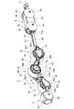
図1乃至図5に示すように、本発明の第1の実施例に係る配管内移動装置1は、3個の車輪2A,2B,2Cと、隣り合う車輪2A,2B及び2B,2C間を水平方向及び垂直方向へ揺動可能に連結する2個のジョイント部3A,3Bと、先頭の車輪2Aの前方に配置された視覚部4と、走行方向へ縦並びに配置された3個の車輪2A〜2CをV字状に配置させるように張力を付与してV字状に折り曲げる2本の操縦用ケーブル5X,5Yと、2本の操縦用ケーブル5X,5Yの張力を調節可能な張力調節部6等を備えて構成されている。   As shown in FIGS. 1 to 5, the in-pipe moving device 1 according to the first embodiment of the present invention includes three wheels 2 </ b> A, 2 </ b> B, 2 </ b> C and adjacent wheels 2 </ b> A, 2 </ b> B and 2 </ b> B, 2 </ b> C. Two joint parts 3A and 3B that are connected so as to be swingable in the horizontal direction and the vertical direction, a visual part 4 arranged in front of the leading wheel 2A, and three wheels 2A arranged vertically in the traveling direction. ~ 2C can be arranged in a V shape and tension is applied to the two control cables 5X, 5Y to be bent into a V shape, and a tension adjustment unit capable of adjusting the tension of the two control cables 5X, 5Y 6 etc. are comprised.

しかしながら、配管内移動装置1としては、車輪を4個用い、且つ、ジョイント部を3個用いて構成することができる。更に、車輪を5個以上用い、且つ、ジョイント部を車輪よりも1個少ない4個以上用いて配管内移動装置を構成することもできる。この実施例では、3個の車輪2A,2B,2Cと2個のジョイント部3A,3Bを用いた配管内移動装置1について説明する。   However, the in-pipe moving device 1 can be configured using four wheels and three joint portions. Furthermore, the in-pipe moving device can be configured by using five or more wheels and using four or more joint portions, which are one fewer than the wheels. In this embodiment, an in-pipe moving apparatus 1 using three wheels 2A, 2B, 2C and two joint portions 3A, 3B will be described.

配管内移動装置1の3個の車輪2A,2B,2Cは、図6乃至図8に示すように、その基本的構成は同一であり、駆動モータ11と、この駆動モータ11の回転部12と一体的に回転駆動されるホイール15と、このホイール15の外周面に一体的に設けられたタイヤ16と、を備えて構成されている。駆動モータ11の回転部12とタイヤ16を有するホイール15とは連結部材17を介して連結されて一体的に構成されている。   As shown in FIGS. 6 to 8, the three wheels 2A, 2B, and 2C of the in-pipe moving device 1 have the same basic configuration. The drive motor 11 and the rotating portion 12 of the drive motor 11 A wheel 15 that is integrally rotated and a tire 16 that is integrally provided on the outer peripheral surface of the wheel 15 are provided. The rotating part 12 of the drive motor 11 and the wheel 15 having the tire 16 are connected via a connecting member 17 and are integrally formed.

駆動モータ11は、電力の供給を受けて機械動力を発生する原動機であり、その構成は周知であるため、ここでは構成の概略を説明する。この実施例で示す駆動モータ11は、水平方向の一側に開口する穴を有する円筒状の筒体からなる固定部(車軸支持部)13と、その固定部13の穴に挿入されて回転自在に支持されている回転部12とからなり、回転部12の一端が固定部13の側方に突出されている。回転部12は、モータの回転軸の一側に固定された円筒状をなす減速機を有しており、その減速機の一端が固定部13の一端から側方へ突出されている。この減速機はモータの回転数を適宜に減速して回転部12から出力させるもので、先端にはスプライン軸部22が設けられており、このスプライン軸部22が連結部材17のスプライン受け穴に挿入され、固定ネジ18によってネジ止めされている。   The drive motor 11 is a prime mover that receives mechanical power and generates mechanical power. Since the configuration is well known, the outline of the configuration will be described here. A drive motor 11 shown in this embodiment is inserted into a fixing portion (axle support portion) 13 formed of a cylindrical tube having a hole opened on one side in a horizontal direction, and is inserted into a hole of the fixing portion 13 to freely rotate. And one end of the rotating part 12 protrudes to the side of the fixed part 13. The rotating part 12 has a cylindrical reduction gear fixed to one side of the rotation shaft of the motor, and one end of the reduction gear projects from one end of the fixing part 13 to the side. The speed reducer appropriately reduces the rotational speed of the motor and outputs it from the rotating part 12. A spline shaft part 22 is provided at the tip, and the spline shaft part 22 is inserted into the spline receiving hole of the connecting member 17. It is inserted and fixed with a fixing screw 18.

連結部材17は、図6及び図8に示すように、一端が端面片によって閉じられた筒状の胴体部17aと、この胴体部17aの開口側端部に連続して半径方向外側へ広がるように形成されたフランジ部17bとを有している。連結部材17の胴体部17aには、端面片の中央部に穿設された通し穴20と、胴体部17aの外周面に設けた周方向に連続する環状溝21とが設けられている。この胴体部17aのスプライン受け穴に回転部12のスプライン軸部22が嵌合されており、通し穴20を貫通する固定ネジ18のネジ部をスプライン軸部22の端面中央に設けたネジ孔に螺合して締め付けることにより、連結部材17が回転部12にスプライン結合されて回転方向に一体とされている。   As shown in FIGS. 6 and 8, the connecting member 17 extends continuously outward in the radial direction continuously to a cylindrical body portion 17 a whose one end is closed by an end face piece and an opening side end portion of the body portion 17 a. And a flange portion 17b formed on the surface. The body portion 17a of the connecting member 17 is provided with a through hole 20 formed in the center portion of the end face piece and an annular groove 21 provided in the outer circumferential surface of the body portion 17a in the circumferential direction. The spline shaft portion 22 of the rotating portion 12 is fitted in the spline receiving hole of the body portion 17 a, and the screw portion of the fixing screw 18 that penetrates the through hole 20 is a screw hole provided at the center of the end surface of the spline shaft portion 22. By screwing and tightening, the connecting member 17 is splined to the rotating portion 12 and integrated in the rotating direction.

連結部材17のフランジ部17bの半径方向外側には周方向に等間隔に配置された複数の通し穴が設けられており、これらの通し穴に対応するネジ孔がホイール15の端面に同数設けられている。これらの通し穴を貫通する固定ネジ23のネジ部をホイール15に設けたネジ孔に螺合して締め付けることにより、フランジ部17bがホイール15に固定されている。これにより、連結部材17を介して回転部12とホイール15とが連結され、駆動モータ11を駆動することにより回転部12の回転方向に応じて、タイヤ16を有するホイール15が回転部12と一体的に同方向へ回転駆動される。タイヤ16の材質としては、例えば、ウレタンゴムが好適である。しかしながら、タイヤ16の材質としては、これに限定されるものではなく、シリコンゴムその他のゴム状弾性体を用いることができる。   A plurality of through holes arranged at equal intervals in the circumferential direction are provided on the outer side in the radial direction of the flange portion 17 b of the connecting member 17, and the same number of screw holes corresponding to these through holes are provided on the end surface of the wheel 15. ing. The flange portion 17 b is fixed to the wheel 15 by screwing the screw portion of the fixing screw 23 penetrating these through holes into the screw hole provided in the wheel 15 and tightening. Thereby, the rotating part 12 and the wheel 15 are connected via the connecting member 17, and the wheel 15 having the tire 16 is integrated with the rotating part 12 according to the rotation direction of the rotating part 12 by driving the drive motor 11. Are driven to rotate in the same direction. As a material of the tire 16, for example, urethane rubber is suitable. However, the material of the tire 16 is not limited to this, and silicon rubber and other rubber-like elastic bodies can be used.

図6に示すように、駆動モータ11の固定部13には、連結部材17と反対側において固定リング25と揺動リンク26が回動可能に嵌合されている。固定リング25は複数の固定ネジ27によって固定部13の外周に締付固定されており、この固定リング25の外側に配置された揺動リング26は固定部13に対して回動可能とされている。揺動リング26は、固定部13の端面に固定ネジ28で固定された固定プレート29によって抜け止めされている。そして、固定プレート29の外側には、固定ネジ31によってカバープレート32がネジ止めされている。   As shown in FIG. 6, a fixing ring 25 and a swing link 26 are rotatably fitted to the fixing portion 13 of the drive motor 11 on the side opposite to the connecting member 17. The fixing ring 25 is fastened and fixed to the outer periphery of the fixing portion 13 by a plurality of fixing screws 27, and the swinging ring 26 disposed outside the fixing ring 25 is rotatable with respect to the fixing portion 13. Yes. The oscillating ring 26 is prevented from coming off by a fixing plate 29 fixed to the end face of the fixing portion 13 with a fixing screw 28. A cover plate 32 is screwed to the outside of the fixed plate 29 by a fixing screw 31.

これにより、駆動モータ11の固定部13に対して固定リング25と固定プレート29とカバープレート32とが固定されていて、この固定部13に対して回転部12と揺動リング26とが回転自在に支持された構成となっている。このような構成が3個の車輪2A〜2Cに共通する基本構成であり、先頭から2番目の車輪2Bのみに回転リング33が追加的に取り付けられている。   As a result, the fixing ring 25, the fixing plate 29, and the cover plate 32 are fixed to the fixing portion 13 of the drive motor 11, and the rotating portion 12 and the swing ring 26 are rotatable with respect to the fixing portion 13. It is the structure supported by. Such a configuration is a basic configuration common to the three wheels 2A to 2C, and the rotation ring 33 is additionally attached only to the second wheel 2B from the top.

回転リング33は、図6に示すように、連結部材17の胴体部17aに回転自在に嵌合されている。回転リング33の外周面には周方向に連続する環状溝34が設けられており、その環状溝34には第1の操縦用ケーブル5Xが摺動可能に巻回される。この回転リング33は、胴体部17aに設けた環状溝21に装着される止め輪35によって抜け止めされ、連結部材17によって回転自在に支持されている。   As shown in FIG. 6, the rotating ring 33 is rotatably fitted to the body portion 17 a of the connecting member 17. An annular groove 34 that is continuous in the circumferential direction is provided on the outer peripheral surface of the rotating ring 33, and the first steering cable 5 </ b> X is slidably wound around the annular groove 34. The rotating ring 33 is prevented from coming off by a retaining ring 35 attached to the annular groove 21 provided in the body portion 17a, and is rotatably supported by the connecting member 17.

図1及び図7等に示すように、先頭に位置する(1両目)車輪2Aでは、同図において左側となる走行方向の前側を向いた状態において、駆動モータ11の回転軸の軸方向の左側面に固定リング25Aと揺動リング26Aが配置され、図に表れない右側面に連結部材が配置されている。そして、車輪2Aの中心から遠い位置に配置された揺動リング26Aに設けた半径方向外側に突出するアーム部26aを走行方向の前方に向けると共に、そのアーム部26aに前側ブラケット37がネジ止めされて固定されている。前側ブラケット37は、車輪2Aの前方を横断するように延在されており、この前側ブラケット37に視覚部4が固定されている。   As shown in FIGS. 1 and 7, etc., the wheel 2A located at the head (first car) has a left side in the axial direction of the rotating shaft of the drive motor 11 in a state of facing the front side in the running direction which is the left side in the figure. The fixed ring 25A and the swing ring 26A are arranged on the surface, and the connecting member is arranged on the right side surface not shown in the drawing. Then, the arm portion 26a protruding outward in the radial direction provided on the swing ring 26A disposed at a position far from the center of the wheel 2A is directed forward in the traveling direction, and the front bracket 37 is screwed to the arm portion 26a. Is fixed. The front bracket 37 extends so as to cross the front of the wheel 2 </ b> A, and the visual part 4 is fixed to the front bracket 37.

図1〜図4及び図7に示すように、揺動リング26Aの内側に配置されている固定リング25Aに設けた半径方向外側に突出するアーム部25aは走行方向の後方に向けられており、そのアーム部25aに連結ボックス38Aがネジ止めされて固定されている。連結ボックス38Aは断面形状がコ字状をなしており、その上面片38mと下面片38nとの間に連結アーム39Aが挿入されている。この連結アーム39Aは、先頭から2番目(2両目)の車輪2Bに回動可能に支持される揺動リング26Bのアーム部26bに固定されている。   As shown in FIG. 1 to FIG. 4 and FIG. 7, the arm portion 25 a protruding outward in the radial direction provided on the fixed ring 25 </ b> A disposed inside the swing ring 26 </ b> A is directed rearward in the traveling direction, The connecting box 38A is fixed to the arm portion 25a with screws. The connection box 38A has a U-shaped cross section, and a connection arm 39A is inserted between the upper surface piece 38m and the lower surface piece 38n. The connecting arm 39A is fixed to the arm portion 26b of the swing ring 26B that is rotatably supported by the second (second car) wheel 2B from the top.

この2両目の車輪2Bに設けられた連結アーム39Aと1両目の車輪2Aに設けられた連結ボックス38Aとは、連結アーム39Aを貫通して連結ボックス38Aに両端支持される枢軸によって水平方向へ回動可能に連結されている。これにより、1両目の車輪2Aの固定リング25Aと2両目の車輪2Bの揺動リング26Bとが連結ボックス38Aと連結アーム39Aを介して水平方向へ揺動可能に連結されている。また、揺動リング26Bが2両目の車輪2Bの固定部13に回動自在に嵌合されているため、固定リング25Aと揺動リング26Bとが垂直方向へ相対的に揺動変位可能とされている。   The connecting arm 39A provided on the second wheel 2B and the connecting box 38A provided on the first wheel 2A are rotated in the horizontal direction by a pivot that penetrates the connecting arm 39A and is supported at both ends by the connecting box 38A. It is linked movably. As a result, the fixed ring 25A of the first wheel 2A and the swing ring 26B of the second wheel 2B are connected via the connection box 38A and the connection arm 39A so as to be swingable in the horizontal direction. Further, since the swing ring 26B is rotatably fitted to the fixed portion 13 of the second wheel 2B, the fixed ring 25A and the swing ring 26B can be relatively displaced in the vertical direction. ing.

また、連結ボックス38Aの上面片38mの上面中央には、2本の操縦用ケーブル5X,5Yの先頭側の端部を固定支持するためのケーブル固定箱41がネジ止めされて固定されている。この連結ボックス38Aの下面片38nの左右両側部には、ケーブル固定箱41から引き出された2本の操縦用ケーブル5X,5Yを個別にガイドする2個のガイドピン42がネジ止めされている。これら連結ボックス38Aと連結アーム39Aと固定リング25Aと揺動リング26Bとによって、1両目の車輪2Aと2両目の車輪2Bとの間を水平方向及び垂直方向へ揺動可能に連結する第1のジョイント部3Aが構成されている。   Further, a cable fixing box 41 for fixing and supporting the leading end portions of the two steering cables 5X and 5Y is fixed with screws at the center of the upper surface of the upper surface piece 38m of the connection box 38A. Two guide pins 42 for individually guiding the two steering cables 5X and 5Y drawn from the cable fixing box 41 are screwed to the left and right sides of the lower surface piece 38n of the connection box 38A. A first box for connecting the first wheel 2A and the second wheel 2B so as to be swingable in the horizontal and vertical directions by the connection box 38A, the connection arm 39A, the fixing ring 25A and the swing ring 26B. The joint portion 3A is configured.

2両目の車輪2Bの揺動リング26Bの内側には固定リング25Bが配置されており、その固定リング25Bのアーム部25bが後方に延在されていて、そのアーム部25bに第2のジョイント部3Bの連結ボックス38Bが固定されている。この連結ボックス38Bには第2のジョイント部3Bの連結アーム39Bが差し込まれており、その連結アーム39Bを貫通して連結ボックス38Bに両端支持される枢軸によって水平方向へ回動可能に連結されている。   A fixing ring 25B is disposed inside the swing ring 26B of the second wheel 2B, and an arm portion 25b of the fixing ring 25B extends rearward, and a second joint portion is connected to the arm portion 25b. A 3B connection box 38B is fixed. A connecting arm 39B of the second joint portion 3B is inserted into the connecting box 38B, and is connected to the connecting box 39B so as to be rotatable in the horizontal direction by pivots supported at both ends by the connecting box 38B. Yes.

連結ボックス38Bの下面には、2本の操縦用ケーブル5X,5Yの引き出し方向を変更する回転型のケーブルガイド部材9が設けられている。ケーブルガイド部材9は、図6〜図8等に示すように、4個のガイドプーリ50と、この4個のガイドプーリ50を支える支持プレート51と、この支持プレート51を連結ボックス38Bの下面にネジ止めして4個のガイドプーリ50を回動可能に支持する2個の取付ネジ52とによって構成されている。支持プレート51は、駆動モータ11の回転軸と平行する方向に延在されており、その長手方向の両側において2個のガイドプーリ50が重ね合された状態で配置されている。この支持プレート51を2個の取付ネジ52で固定することにより、2個のガイドプーリ50が車輪2Bの後方において、その回転軸と平行する方向の両側にそれぞれ回動自在に配置されている。   On the lower surface of the connection box 38B, there is provided a rotary type cable guide member 9 for changing the pulling direction of the two steering cables 5X and 5Y. 6 to 8 and the like, the cable guide member 9 includes four guide pulleys 50, a support plate 51 that supports the four guide pulleys 50, and the support plate 51 on the lower surface of the connection box 38B. It is composed of two mounting screws 52 that are screwed to support the four guide pulleys 50 in a rotatable manner. The support plate 51 extends in a direction parallel to the rotation axis of the drive motor 11, and is arranged in a state where two guide pulleys 50 are overlapped on both sides in the longitudinal direction. By fixing the support plate 51 with the two mounting screws 52, the two guide pulleys 50 are respectively disposed on both sides in the direction parallel to the rotation axis behind the wheel 2B.

第2のジョイント部3Bの連結アーム39Bは3両目の車輪2Cの駆動モータ11の固定部13に固定される固定リング25Cのアーム部25cに固定されている。これにより、2両目の車輪2Bの固定リング25Bと3両目の車輪2Cの固定リング25Cとが連結ボックス38Bと連結アーム39Bを介して水平方向へ揺動可能とされている。これら連結ボックス38Bと連結アーム39Bと固定リング25Bと固定リング25Cとによって、2両目の車輪2Bと3両目の車輪2Cとの間を水平方向へ揺動可能に連結する第2のジョイント部3Bが構成されている。   The connecting arm 39B of the second joint part 3B is fixed to the arm part 25c of the fixing ring 25C fixed to the fixing part 13 of the drive motor 11 of the third wheel 2C. As a result, the fixing ring 25B of the second wheel 2B and the fixing ring 25C of the third wheel 2C can swing in the horizontal direction via the connection box 38B and the connection arm 39B. A second joint portion 3B that connects the second wheel 2B and the third wheel 2C so as to be swingable in the horizontal direction by the connection box 38B, the connection arm 39B, the fixing ring 25B, and the fixing ring 25C is provided. It is configured.

この場合、2両目の車輪2Bの駆動モータ11の固定部13に固定リング25Bが固定され、3両目の車輪2Cの駆動モータ11の固定部13に固定リング25Cが固定されている。そのため、2両目の車輪2Bの固定リング25Bと3両目の車輪2Cの固定リング25Cとは、連結ボックス38Bと連結アーム39Bを中心として、水平方向へは揺動可能であるが、垂直方向へは揺動できない状態となっている。しかしながら、かかる場合においても、2つの車輪2B,2Cの2つの固定部13自体が姿勢変更可能であるため、2番目の車輪2Bを中心として前後の車輪2A,2Cによって形成される折れ曲げ角を調節することが可能である。   In this case, the fixing ring 25B is fixed to the fixing portion 13 of the driving motor 11 of the second wheel 2B, and the fixing ring 25C is fixed to the fixing portion 13 of the driving motor 11 of the third wheel 2C. Therefore, the fixing ring 25B of the second wheel 2B and the fixing ring 25C of the third wheel 2C can swing in the horizontal direction around the connection box 38B and the connection arm 39B, but in the vertical direction. Cannot swing. However, even in such a case, since the two fixing portions 13 themselves of the two wheels 2B and 2C can be changed in posture, the bending angle formed by the front and rear wheels 2A and 2C around the second wheel 2B is set. It is possible to adjust.

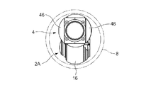
視覚部4は、配管8内の状態を目視によって認識するためのもので、例えば、監視カメラを用いて構成することができる。視覚部4は、前側ブラケット37の前面に固定されたカメラケース45と、このカメラケース45内に収納された図示しない監視カメラと、カメラケース45に取り付けられた一対のカメラホイール46,46等を備えて構成されている。監視カメラは、カメラケース45の前方の窓から走行方向の前方を撮影し、その情報を後述する制御装置に送信すると共に、配管内移動装置1を操縦する者に視覚で視認できる機能を有している。また、前側ブラケット37と固定リング25Aとの間にはコイルバネ37aが架け渡されており、このコイルバネ37aのバネ力によって視覚部4が常に走行方向の前方を向くように調整されている。   The visual unit 4 is for visually recognizing the state in the pipe 8 and can be configured using, for example, a surveillance camera. The visual unit 4 includes a camera case 45 fixed to the front surface of the front bracket 37, a monitoring camera (not shown) housed in the camera case 45, a pair of camera wheels 46 and 46 attached to the camera case 45, and the like. It is prepared for. The surveillance camera captures the front in the traveling direction from the window in front of the camera case 45, transmits the information to a control device to be described later, and has a function that can be visually recognized by a person who operates the in-pipe moving device 1. ing. A coil spring 37a is bridged between the front bracket 37 and the fixing ring 25A, and the visual part 4 is always adjusted to face forward in the traveling direction by the spring force of the coil spring 37a.

一対のカメラホイール46,46は、カメラケース45の左右両側に配置されており、カメラケース45の両側部に突出された支持軸にフリーな状態で回転自在に支持されている。更に、一対のカメラホイール46,46は、外周面が球体の曲面の一部をなすように湾曲形成された円盤形状とされており、これにより、カメラケース45が配管8内面に接触するのを防止し若しくはその接触が最小限となるようにしている。この実施例では、一対のカメラホイール46,46は、回転自在なフリー状態とされているが、カメラケース45の内部にモータ等の動力源を設け、一対のカメラホイール46,46をモータ駆動する構成とすることもできる。   The pair of camera wheels 46, 46 are arranged on the left and right sides of the camera case 45, and are rotatably supported in a free state on support shafts protruding on both sides of the camera case 45. Further, the pair of camera wheels 46 and 46 are formed in a disk shape whose outer peripheral surface is curved so as to form a part of the curved surface of the sphere, so that the camera case 45 contacts the inner surface of the pipe 8. To prevent or minimize such contact. In this embodiment, the pair of camera wheels 46 and 46 are in a freely rotatable state. However, a power source such as a motor is provided inside the camera case 45 to drive the pair of camera wheels 46 and 46 with a motor. It can also be configured.

3両目の車輪2Cの駆動モータ11の固定部13に回転自在に支持される揺動リング26Cのアーム部26cには後側ブラケット48が固定されている。後側ブラケット48は、3両目の車輪2Cの後方を水平方向へ横切るように延在されている。この後側ブラケット48には板バネ49の長手方向の一端が固定されている。板バネ49は水平方向に展開されており、その長手方向の他端が張力調節部6の端部75aに固定されている。   A rear bracket 48 is fixed to the arm portion 26c of the swing ring 26C that is rotatably supported by the fixing portion 13 of the drive motor 11 of the third wheel 2C. The rear bracket 48 extends so as to cross the rear of the third wheel 2C in the horizontal direction. One end of the leaf spring 49 in the longitudinal direction is fixed to the rear bracket 48. The leaf spring 49 is expanded in the horizontal direction, and the other end in the longitudinal direction is fixed to the end 75 a of the tension adjusting unit 6.

図1〜図4に示すように、2本の操縦用ケーブル5X,5Yの先頭側の端部は、1両目の車輪2Aの固定リング25Aと一体の連結ボックス38Aに固定されたケーブル固定箱41に固定されている。2本の操縦用ケーブル5X,5Yの固定手段としては、例えば、ケーブル固定箱41に対する操縦用ケーブル5X,5Yのロウ付けや半田付け等の固着手段で固定するが、その固定部の周りにニクロム線を巻き付け、通電時にこの固定を解除可能として、非常時解除機構を設けることもできる。これによれば、非常時に車輪2A〜2Cの配管8内壁への押し付け力を無くすことができ、配管内移動装置1を手動で回収することが可能となる。   As shown in FIGS. 1 to 4, the leading ends of the two steering cables 5X and 5Y are cable fixing boxes 41 fixed to a connecting box 38A integrated with the fixing ring 25A of the first wheel 2A. It is fixed to. As the fixing means for the two steering cables 5X and 5Y, for example, the steering cables 5X and 5Y are fixed to the cable fixing box 41 by fixing means such as brazing or soldering. An emergency release mechanism can be provided so that the wire can be wound and the fixation can be released when energized. According to this, the pressing force to the inner wall of the pipe 8 of the wheels 2A to 2C can be eliminated in an emergency, and the in-pipe moving device 1 can be manually recovered.

ケーブル固定箱41から引き出された2本の操縦用ケーブル5X,5Yは、連結ボックス38Aの反対側において、その連結ボックス38Aに固定されているガイドピン42によって個別に巻回され、そのガイドピン42により方向を変更されて後頭側に延在されている。   The two steering cables 5X and 5Y drawn out from the cable fixing box 41 are individually wound by guide pins 42 fixed to the connection box 38A on the opposite side of the connection box 38A. The direction is changed by, and it is extended to the occipital side.

2両目の車輪2Bにおいて、2本の操縦用ケーブル5X,5Yのうち、第1の操縦用ケーブル5Xは、駆動モータ11の回転部12と一体に回転する連結部材17に回転自在に支持されている回転リング33の環状溝34内に摺動可能に巻回され、その後方からケーブルガイド部材9側に引き出されている。また、第2の操縦用ケーブル5Yは、駆動モータ11の固定部13に固定されている固定プレート29に設けた通路29aを通過して、その後方からケーブルガイド部材9側に引き出されている。   Of the two steering cables 5X and 5Y, the first steering cable 5X is rotatably supported by a connecting member 17 that rotates integrally with the rotating portion 12 of the drive motor 11 in the second wheel 2B. It is slidably wound in an annular groove 34 of the rotating ring 33 and is pulled out from the rear side to the cable guide member 9 side. The second steering cable 5 </ b> Y passes through a passage 29 a provided in a fixed plate 29 fixed to the fixing portion 13 of the drive motor 11, and is pulled out from the rear side to the cable guide member 9 side.

回転リング33から引き出された第1の操縦用ケーブル5Xは、その引出し側に対向された側に位置するケーブルガイド部材9の一方のガイドプーリ50(図3A,3Bにおいて車輪2Bの左側)に略半周程度巻き付けられ、そこから反対側に位置する一方のガイドプーリ50(図3A,3Bにおいて車輪2Bの右側)に略半周程度巻き付けられる。そして、3両目の車輪2Cの側方を通過して、車輪2Cの固定リング25Cに一端を固定し、他端を張力調節部6に固定されたチューブワイヤ74の中を通過し、第2の送りナット64に他端が固定されている。   The first steering cable 5X pulled out from the rotating ring 33 is substantially connected to one guide pulley 50 (the left side of the wheel 2B in FIGS. 3A and 3B) of the cable guide member 9 located on the side facing the pull-out side. It is wound about a half turn, and is wound about a half turn around one guide pulley 50 (on the right side of the wheel 2B in FIGS. 3A and 3B) located on the opposite side. Then, after passing through the side of the third wheel 2C, one end is fixed to the fixing ring 25C of the wheel 2C, the other end is passed through the tube wire 74 fixed to the tension adjusting unit 6, and the second The other end is fixed to the feed nut 64.

また、回転リング33から引き出された第2の操縦用ケーブル5Yは、その引出し側に対向された側に位置するケーブルガイド部材9の他方のガイドプーリ50(図3A,3Bにおいて車輪2Bの右側)に略半周程度巻き付けられ、そこから反対側に位置する他方のガイドプーリ50(図3A,3Bにおいて車輪2Bの左側)に略半周程度巻き付けられる。そして、同じく3両目の車輪2Cの側方を通過して、車輪2Cの固定リング25Cに一端を固定し、他端を張力調節部6に固定されたチューブワイヤ74の中を通過し、第1の送りナット64に他端が固定される。   Further, the second steering cable 5Y drawn from the rotating ring 33 is connected to the other guide pulley 50 of the cable guide member 9 located on the side facing the drawing side (the right side of the wheel 2B in FIGS. 3A and 3B). Is wound around the other guide pulley 50 (the left side of the wheel 2B in FIGS. 3A and 3B) located on the opposite side. Similarly, it passes through the side of the third wheel 2C, one end is fixed to the fixing ring 25C of the wheel 2C, and the other end passes through the tube wire 74 fixed to the tension adjusting unit 6, and the first The other end is fixed to the feed nut 64.

張力調節部6は、図1〜図4、図7及び図9〜図11に示すような構成を有している。張力調節部6は、2本の操縦用ケーブル5X,5Yの張力を個別に調節可能な同一構成からなる2組の調節機構を備えている。図9〜図11において詳細に示すように、1組の調節機構は、略長方形の箱体からなるフレーム55と、このフレーム55に内蔵されたモータ組立体56と、操縦用ケーブル5X,5Yに張力を付与するバネ部材57と、フレーム55に取り付けられた走行ホイール58等を備えて構成されている。   The tension adjusting unit 6 has a configuration as shown in FIGS. 1 to 4, 7 and 9 to 11. The tension adjusting unit 6 includes two sets of adjusting mechanisms having the same configuration capable of individually adjusting the tensions of the two steering cables 5X and 5Y. As shown in detail in FIG. 9 to FIG. 11, the set of adjusting mechanisms includes a frame 55 formed of a substantially rectangular box, a motor assembly 56 built in the frame 55, and the steering cables 5X and 5Y. A spring member 57 for applying tension, a traveling wheel 58 attached to the frame 55, and the like are provided.

フレーム55は、両端が開口された断面形状が四角形をなす筒体からなり、その前面側は前プレート60によって閉じられ、後面側は後プレート61によって閉じられている。前プレート60と後プレート61との間には、モータ組立体56と送りネジ63と送りナット64とガイドバー65と変位センサ66が収容されている。   The frame 55 is formed of a cylinder having a square cross section with both ends opened, and the front side is closed by the front plate 60 and the rear side is closed by the rear plate 61. A motor assembly 56, a feed screw 63, a feed nut 64, a guide bar 65, and a displacement sensor 66 are accommodated between the front plate 60 and the rear plate 61.

モータ組立体56は、軸方向に直列に接続されたモータ56aと、そのモータ56aの回転数を減速して出力する減速機56bとからなり、減速機56bの回転軸がモータ組立体56の出力軸56cとして後プレート61を貫通して後方に突出されている。出力軸56cには駆動ギア68が固定されており、その駆動ギア68には従動ギア69が噛合されている。従動ギア69は、後プレート61にベアリング71を介して回転自在に支持された送りネジ63の一端に固定されている。   The motor assembly 56 includes a motor 56 a connected in series in the axial direction, and a speed reducer 56 b that decelerates and outputs the rotational speed of the motor 56 a, and the rotation shaft of the speed reducer 56 b is the output of the motor assembly 56. The shaft 56c protrudes rearward through the rear plate 61. A drive gear 68 is fixed to the output shaft 56c, and a driven gear 69 is engaged with the drive gear 68. The driven gear 69 is fixed to one end of a feed screw 63 that is rotatably supported by the rear plate 61 via a bearing 71.

送りネジ63のネジ部には送りナット64が軸方向へ移動可能に螺合されており、この送りナット64に操縦用ケーブル5X(又は5Y)の後端が固定されている。送りナット64には、送りネジ63と平行に配置されたガイドバー65が摺動可能に貫通されており、そのガイドバー65は前プレート60と後プレート61とによって両端支持されている。   A feed nut 64 is screwed to the thread portion of the feed screw 63 so as to be movable in the axial direction, and the rear end of the steering cable 5X (or 5Y) is fixed to the feed nut 64. A guide bar 65 disposed parallel to the feed screw 63 is slidably passed through the feed nut 64, and the guide bar 65 is supported at both ends by a front plate 60 and a rear plate 61.

前プレート60の前面にはバネ部材の一具体例を示す板バネ57がネジ止めされて固定されている。図9に示すように、板バネ57は、略円盤形に形成された板状の部材からなり、その平面部の中央に所定の隙間をあけて2つのバネ片57aが設けられている。2つのバネ片57aは、コ字状の溝を点対称に配置することによって形成されており、操縦用ケーブル5X,5Yに引張力が加わるときに、それと同じ圧縮力がチューブワイヤ74から張力調節部6のフレーム55に加わる効果でバネ片57aが微小に撓む効果を変位センサ66で計測することにより、チューブワイヤ74の張力を計測できるように構成されている。なお、操縦用ケーブル5X,5Yはバネ片57aには固定されておらず、そのバネ片57aに設けた穴を貫通して送りナット64に固定されている。   A plate spring 57 showing a specific example of a spring member is fixed to the front surface of the front plate 60 with screws. As shown in FIG. 9, the plate spring 57 is made of a plate-like member formed in a substantially disk shape, and two spring pieces 57a are provided with a predetermined gap in the center of the plane portion. The two spring pieces 57a are formed by arranging U-shaped grooves symmetrically with respect to a point. When a tensile force is applied to the steering cables 5X and 5Y, the same compression force is applied from the tube wire 74 to adjust the tension. The tension of the tube wire 74 can be measured by measuring, with the displacement sensor 66, the effect that the spring piece 57a bends slightly due to the effect applied to the frame 55 of the portion 6. The steering cables 5X and 5Y are not fixed to the spring pieces 57a, but are fixed to the feed nuts 64 through holes formed in the spring pieces 57a.

バネ片57aの基部には固定管73が取り付けられており、この固定管73を介して2本のチューブワイヤ74の一端がそれぞれ固定されている。チューブワイヤ74は操縦用ケーブル5X及び5Yが生成する引張力を支持する圧縮力を受けるためのものであり、同時に操縦用ケーブル5X,5Yを保護する役目も果たすものであって、その他端は3両目の車輪2に取り付けられた連結アーム39Bに個別に固定されている。前プレート60の前面には前カバー75が取り付けられており、その前カバー75に設けたブラケット75aに板バネ49の他端が固定されている。   A fixed tube 73 is attached to the base of the spring piece 57a, and one ends of two tube wires 74 are fixed through the fixed tube 73, respectively. The tube wire 74 is for receiving a compressive force that supports the tensile force generated by the steering cables 5X and 5Y. At the same time, the tube wire 74 also serves to protect the steering cables 5X and 5Y. It is individually fixed to a connecting arm 39B attached to the wheels 2 of both eyes. A front cover 75 is attached to the front surface of the front plate 60, and the other end of the leaf spring 49 is fixed to a bracket 75 a provided on the front cover 75.

変位センサ66は、操縦用ケーブル5X,5Yの張力に相当する圧縮力がチューブワイヤ74から加えられたとき、その圧縮力によってバネ片57aが弾性変形するときの、そのバネ片57aの変位量を検出し、その変位量に基づいて操縦用ケーブル5X,5Yの張力を計測し、その情報で操縦用ケーブル5X,5Yの張力を配管内移動装置1の走行状態に適した値に制御し、望ましい状態で走行するために使用されるものである。   The displacement sensor 66 indicates the amount of displacement of the spring piece 57a when the spring piece 57a is elastically deformed by the compression force when a compressive force corresponding to the tension of the control cables 5X and 5Y is applied from the tube wire 74. Detecting and measuring the tension of the steering cables 5X and 5Y based on the amount of displacement, and controlling the tension of the steering cables 5X and 5Y to a value suitable for the traveling state of the in-pipe moving device 1 based on the information, is desirable. It is used for traveling in a state.

なお、後プレート61の背面には、駆動ギア68と従動ギア69を囲って保護する後カバー76が取り付けられている。そして、後カバー76には、図示しない制御装置と連結するための接続具77が取り付けられている。   A rear cover 76 that surrounds and protects the drive gear 68 and the driven gear 69 is attached to the rear surface of the rear plate 61. The rear cover 76 is attached with a connection tool 77 for coupling with a control device (not shown).

4個の走行ホイール58は、フレーム55の前後及び左右の4箇所に配置されており、フレーム55の両側部に突出された支持軸にフリーな状態で回転自在に支持されている。4個の走行ホイール58は、外周面が球体の曲面の一部をなすように湾曲形成された円盤形状に形成されている。これにより、配管8内において直線走行及び旋回走行が自由且つ容易に行えるようにしている。この実施例では、4個の走行ホイール58は、回転自在なフリー状態とされているが、フレーム55の内部にモータ等の動力源を設け、前輪又は後輪の一方又は両方をモータ駆動する構成とすることもできる。このような構成を有する張力調節機構が2組設けられている。   The four traveling wheels 58 are arranged at four positions on the front and rear sides and on the left and right sides of the frame 55, and are rotatably supported in a free state on support shafts protruding on both sides of the frame 55. The four traveling wheels 58 are formed in a disk shape that is curved so that the outer peripheral surface forms part of the curved surface of a sphere. As a result, linear travel and turning travel can be performed freely and easily in the pipe 8. In this embodiment, the four traveling wheels 58 are in a freely rotatable state, but a configuration in which a power source such as a motor is provided inside the frame 55 and one or both of the front wheels and the rear wheels are motor-driven. It can also be. Two sets of tension adjusting mechanisms having such a configuration are provided.

図12は、張力調節部6の機能の概略を説明する図である。フレーム55に支持されているモータ組立体56の駆動によって操縦用ケーブル5X,5Yを引っ張り、又は緩めると、これに連動するようにチューブワイヤ74が引っ張り、又は緩められる。このチューブワイヤ74の移動を変位センサ66で検出し、2本の操縦用ケーブル5X,5Yの張力を調整することにより、配管内移動装置1の直線走行や螺旋走行等の走行状態を最適な状態にコントロールすることが可能となる。   FIG. 12 is a diagram for explaining the outline of the function of the tension adjusting unit 6. When the steering cables 5X and 5Y are pulled or loosened by driving the motor assembly 56 supported by the frame 55, the tube wire 74 is pulled or loosened so as to be interlocked therewith. The movement of the tube wire 74 is detected by the displacement sensor 66, and the tension of the two steering cables 5X and 5Y is adjusted, so that the traveling state of the in-pipe moving device 1 such as linear traveling and spiral traveling is in an optimum state. It becomes possible to control.

かくして、モータ組立体56を駆動すると、出力軸56cに固定された駆動ギア68から従動ギア69に回転力が伝達され、送りネジ63が出力軸56cの回転方向に応じて右回転又は左回転される。これにより、図10において、送りナット64がガイドバー65にガイドされて右側に移動すると、その移動量だけ操縦用ケーブル5X,5Yがフレーム55から引き出され、操縦用ケーブル5X,5Yの張力が緩められる。これに対して、送りナット64が左側に移動すると、その移動量だけ操縦用ケーブル5X,5Yがフレーム内に引き込まれ、操縦用ケーブル5X,5Yの張力が強められる。   Thus, when the motor assembly 56 is driven, a rotational force is transmitted from the drive gear 68 fixed to the output shaft 56c to the driven gear 69, and the feed screw 63 is rotated clockwise or counterclockwise depending on the rotation direction of the output shaft 56c. The Accordingly, in FIG. 10, when the feed nut 64 is guided by the guide bar 65 and moves to the right side, the steering cables 5X and 5Y are pulled out from the frame 55 by the moving amount, and the tension of the steering cables 5X and 5Y is loosened. It is done. On the other hand, when the feed nut 64 moves to the left side, the steering cables 5X and 5Y are drawn into the frame by the movement amount, and the tension of the steering cables 5X and 5Y is increased.

この際、操縦用ケーブル5X,5Yの張力を緩めると、これに応じてチューブワイヤ74の圧縮力が弛んだ状態となる。これに対して、操縦用ケーブル5X,5Yの張力を強めると、これに応じてチューブワイヤ74の圧縮力が強められる。このような操縦用ケーブル5X,5Yの操作による張力調節は、2本の操縦用ケーブル5X,5Yにおいて個別に行うことができる。   At this time, when the tension of the steering cables 5X and 5Y is loosened, the compressive force of the tube wire 74 is loosened accordingly. On the other hand, when the tension of the control cables 5X and 5Y is increased, the compressive force of the tube wire 74 is increased accordingly. Such tension adjustment by operating the steering cables 5X and 5Y can be performed individually in the two steering cables 5X and 5Y.

即ち、2本の操縦用ケーブル5X,5Yの張力を同一にすると、3個の車輪2A〜2Cは1本の直線上に並んで走行方向に真っ直ぐ向いた状態となる。この際、2本の操縦用ケーブル5X,5Yの張力が弱い場合には、3個の車輪2A〜2CがV字状に配置されて配管内壁を押し付ける力が弱いものとなる。このような走行状態は、牽引すべきワイヤの長さが短く、配管が水平な状態の場合等に取られる。これに対して、2本の操縦用ケーブル5X,5Yの張力が強い場合には、3個の車輪2A〜2CがV字状に配置されて配管内壁を押し付ける力が強いものとなる。このような走行状態は、牽引すべきワイヤの長さが長くて抵抗が大きい場合や、配管が垂直で登って行かなければならない等の場合に取られる。   That is, when the tensions of the two steering cables 5X and 5Y are made the same, the three wheels 2A to 2C are aligned on one straight line and are in a state of facing straight in the traveling direction. At this time, if the tensions of the two steering cables 5X and 5Y are weak, the three wheels 2A to 2C are arranged in a V shape and the force pressing the inner wall of the pipe is weak. Such a running state is taken when the length of the wire to be pulled is short and the pipe is horizontal. On the other hand, when the tensions of the two steering cables 5X and 5Y are strong, the three wheels 2A to 2C are arranged in a V shape and the force pressing the inner wall of the pipe becomes strong. Such a traveling state is taken when the length of the wire to be pulled is long and the resistance is large, or when the pipe has to be climbed vertically.

一方、2本の操縦用ケーブル5X,5Yの張力を変えると、3個の車輪2A〜2Cは水平方向にく字状に折り曲げられた状態となる。この際、2本の操縦用ケーブル5X,5Yの張力の差が小さい場合には、3個の車輪2A〜2C間の水平方向における角度が小さなものとなる。このような場合には、配管8内において、配管内移動装置1が比較的遅い速度で旋回動作される。これに対して、2本の操縦用ケーブル5X,5Yの張力の差が大きい場合には、3個の車輪2A〜2C間の水平方向における角度が大きなものとなる。このような場合には、配管8内において、配管内移動装置1が比較的早い速度で旋回動作される。   On the other hand, when the tensions of the two steering cables 5X and 5Y are changed, the three wheels 2A to 2C are bent in a horizontal shape in a square shape. At this time, when the difference in tension between the two steering cables 5X and 5Y is small, the angle in the horizontal direction between the three wheels 2A to 2C becomes small. In such a case, the in-pipe moving device 1 is turned in the pipe 8 at a relatively slow speed. On the other hand, when the difference in tension between the two steering cables 5X and 5Y is large, the angle in the horizontal direction between the three wheels 2A to 2C becomes large. In such a case, the in-pipe moving device 1 is turned in the pipe 8 at a relatively high speed.

また、2本の操縦用ケーブル5X,5Yは、ケーブルガイド部材9によって左右方向に延在方向が変更されているため、左右のケーブル張力を変えることによって水平方向に大きく蛇行させることができる。しかも、車輪2Bの軸方向の両側に配置したガイドプーリ50に操縦用ケーブル5X、5Yを通過させているため、大きな摩擦力を発生させることなく、比較的小さな力によって操縦用ケーブル5X,5Yを引っ張り操作することができる。   In addition, since the two steering cables 5X and 5Y are changed in the horizontal direction by the cable guide member 9, they can be greatly meandered in the horizontal direction by changing the left and right cable tension. In addition, since the steering cables 5X and 5Y are passed through the guide pulleys 50 arranged on both sides in the axial direction of the wheel 2B, the steering cables 5X and 5Y are connected with a relatively small force without generating a large frictional force. Can be pulled.

張力調節部6の後方には、図示しないが、配管8の内部の状態を検査する検査装置と、配管内移動装置1の動作を制御するための制御装置とが電気的に接続されている。検査装置は、配管内移動装置1の搬送対象となるもので、配管8内面の付着物の状態、配管内の亀裂や腐食の有無等を検査する装置である。この検査装置としては、例えば、超音波センサや渦流探傷センサ等を適用することができる。制御装置は、視覚部4から送られてきた情報に基づいて3個の車輪2A〜2C、張力調節部6及び検査装置の動作を制御するもので、例えば、マイクロコンピュータ(CPU)、記憶装置(RAM,ROM),入出力装置(I/O)、各種センサ等によって構成される。この制御装置は、配管8の外部において作業者の手動操作によって操作される。   Although not illustrated, an inspection device that inspects the internal state of the pipe 8 and a control device that controls the operation of the in-pipe moving device 1 are electrically connected behind the tension adjusting unit 6. The inspection device is a device to be transported by the in-pipe moving device 1, and is a device for inspecting the state of deposits on the inner surface of the pipe 8, the presence or absence of cracks or corrosion in the pipe, and the like. As this inspection apparatus, for example, an ultrasonic sensor, an eddy current flaw detection sensor, or the like can be applied. The control device controls the operation of the three wheels 2A to 2C, the tension adjusting unit 6 and the inspection device based on the information sent from the visual unit 4, for example, a microcomputer (CPU), a storage device ( RAM, ROM), an input / output device (I / O), various sensors, and the like. This control device is operated by an operator's manual operation outside the pipe 8.

次に、配管内移動装置1の走行動作を説明する。
図14は、水平路8aと、この水平路8aの途中から上方へ立ち上がる垂直路8bを有する配管8内に挿入された配管内移動装置1が水平路8aを直進する状態を説明する図である。
Next, the traveling operation of the in-pipe moving device 1 will be described.
FIG. 14 is a diagram for explaining a state in which the in-pipe moving device 1 inserted into the pipe 8 having the horizontal path 8a and the vertical path 8b rising upward from the middle of the horizontal path 8a goes straight on the horizontal path 8a. .

配管内移動装置1は、先頭の視覚部4から先に配管8内に挿入され、配管8の外で作業者が図示しない制御装置を手動操作することによって走行動作が実行される。
配管内移動装置1は、図14において、水平路8aの右側から左側に向けて移動する。
The in-pipe moving device 1 is inserted into the pipe 8 first from the leading visual unit 4, and a traveling operation is executed by an operator manually operating a control device (not shown) outside the pipe 8.
In-pipe moving device 1 moves from the right side to the left side of horizontal path 8a in FIG.

この場合、配管内移動装置1の3個の車輪2A〜2Cは、張力調節部6によって付与される2本の操縦用ケーブル5X,5Yの張力に基づいて山形に配置された状態となり、1両目の車輪2Aのタイヤ16と3両目の車輪2Cのタイヤ16の下端が水平路8aの下面に接触し、2両目の車輪2Bの上端が水平路8aの上面に接触する。これにより、配管内移動装置1が3個の車輪2A〜2Cによって上下方向から支えられ、走行可能な状態となる。このときの2本の操縦用ケーブル5X,5Yの張力は同一であり、同一の張力で左右から引っ張ることにより、配管内移動装置1は走行方向へ直線状に向けられる。   In this case, the three wheels 2A to 2C of the in-pipe moving device 1 are arranged in a mountain shape based on the tension of the two steering cables 5X and 5Y provided by the tension adjusting unit 6. The lower end of the tire 16 of the second wheel 2A and the lower end of the tire 16 of the third wheel 2C are in contact with the lower surface of the horizontal path 8a, and the upper end of the second wheel 2B is in contact with the upper surface of the horizontal path 8a. As a result, the in-pipe moving device 1 is supported by the three wheels 2A to 2C from above and below, and is ready to travel. The tensions of the two steering cables 5X and 5Y at this time are the same. By pulling from the left and right with the same tension, the in-pipe moving device 1 is linearly directed in the traveling direction.

次に、3個の車輪2A〜2Cの駆動モータ11を等しい速度で等しく回転駆動することにより、配管内移動装置1が直線状に真っ直ぐ進み、左側の位置まで移動する。この際、2両目の車輪2Bが垂直路8bに達すると、その車輪2Bが垂直路8b内に入り込むため、2両目の車輪2Bの回転力が水平路8aの上面に伝達されないことになる。   Next, by driving the drive motors 11 of the three wheels 2A to 2C to rotate equally at the same speed, the in-pipe moving device 1 advances straightly and moves to the left position. At this time, when the second wheel 2B reaches the vertical path 8b, the wheel 2B enters the vertical path 8b, so that the rotational force of the second wheel 2B is not transmitted to the upper surface of the horizontal path 8a.

そこで、視覚部4によって垂直路8aの有無を検出し、垂直路8aの有ることが認識されたところで、その入口から所定距離手前において、配管内移動装置1を90度旋回させる(右旋回又は左旋回のいずれでも良い。)ようにする。この際、2本の操縦用ケーブル5X,5Y間の張力差を大きくすると旋回動作は速くなり、その張力差を小さくすると旋回動作は遅くなる。これにより、1両目の車輪2Aのタイヤ16と3両目の車輪2Cのタイヤ16の各側端が水平路8aの一方の側面に接触し、2両目の車輪2Bの側端が水平路8aの他方の側面に接触する。その結果、配管内移動装置1が3個の車輪2A〜2Cによって左右方向から支えられ、走行可能な状態となる。   Therefore, the presence or absence of the vertical path 8a is detected by the visual unit 4, and when it is recognized that the vertical path 8a is present, the in-pipe moving apparatus 1 is turned 90 degrees (right turn or You can turn either left.) At this time, if the tension difference between the two steering cables 5X and 5Y is increased, the turning operation becomes faster, and if the tension difference is reduced, the turning operation becomes slower. Thereby, each side end of the tire 16 of the first wheel 2A and the tire 16 of the third wheel 2C contacts one side surface of the horizontal path 8a, and the side end of the second wheel 2B is the other side of the horizontal path 8a. Touch the side of the. As a result, the in-pipe moving device 1 is supported from the left and right directions by the three wheels 2A to 2C, and can travel.

その後、2両目の車輪2Bが垂直路8bを通過したところで、配管内移動装置1を逆方向へ90度旋回させ、元の姿勢に復帰させる。このときの配管内移動装置1の状態が、図14において左側に示したものである。このように配管内移動装置1をある角度(例えば、直角に曲がる屈曲部では90度)旋回させ、その後逆方向に同一角度戻す姿勢制御は、水平路の屈曲部を走行する場合にも同様に行われる。   Thereafter, when the second wheel 2B passes through the vertical path 8b, the in-pipe moving device 1 is turned 90 degrees in the reverse direction to return to the original posture. The state of the in-pipe moving device 1 at this time is shown on the left side in FIG. In this way, the posture control in which the in-pipe moving device 1 is turned by a certain angle (for example, 90 degrees in a bent portion that is bent at a right angle) and then returned to the same angle in the opposite direction is the same when traveling on a bent portion of a horizontal road Done.

図15は、水平路8aと、この水平路8aの途中から上方へ立ち上がる垂直路8bを有する配管8内に挿入された配管内移動装置1が水平路8aの途中から垂直路8b内に入り込み、その垂直路8bを上昇する動作を説明する図である。   FIG. 15 shows that the in-pipe moving device 1 inserted into the pipe 8 having the horizontal path 8a and the vertical path 8b rising upward from the middle of the horizontal path 8a enters the vertical path 8b from the middle of the horizontal path 8a. It is a figure explaining the operation | movement which raises the vertical path | route 8b.

図15において、図15Xは配管内移動装置1が水平路8aを移動する状態を示し、図15Yは配管内移動装置1の1両目の車輪2Aが垂直路8bに入り込んだ状態を示し、図15Zは配管内移動装置1の2両目の車輪2Bが垂直路8bに入り込んだ状態を示すものである。   15X shows a state in which the in-pipe moving device 1 moves in the horizontal path 8a, and FIG. 15Y shows a state in which the first wheels 2A of the in-pipe moving device 1 enter the vertical path 8b. Shows a state in which the second wheel 2B of the in-pipe moving device 1 enters the vertical path 8b.

図15Xに示すように、配管8内に挿入された配管内移動装置1は、先頭の視覚部4から提供される視界情報に基づいて駆動制御され、図15において水平路8aの右側から左側に向けて移動する。   As shown in FIG. 15X, the in-pipe moving device 1 inserted into the pipe 8 is driven and controlled based on the field of view information provided from the leading visual unit 4, and from the right side to the left side of the horizontal path 8a in FIG. Move towards.

まず、配管内移動装置1の3個の車輪2A〜2Cは、張力調節部6によって付与される2本の操縦用ケーブル5X,5Yの張力に基づいて山形に配置された状態となり、1両目の車輪2Aのタイヤ16と3両目の車輪2Cのタイヤ16の各下端が水平路8aの下面に接触し、2両目の車輪2Bの上端が水平路8aの上面に接触する。これにより、配管内移動装置1が3個の車輪2A〜2Cによって上下方向から支えられ、走行可能な状態となる。   First, the three wheels 2 </ b> A to 2 </ b> C of the in-pipe moving device 1 are arranged in a mountain shape based on the tension of the two steering cables 5 </ b> X and 5 </ b> Y provided by the tension adjusting unit 6. The lower ends of the tire 16 of the wheel 2A and the tire 16 of the third wheel 2C contact the lower surface of the horizontal path 8a, and the upper end of the second wheel 2B contacts the upper surface of the horizontal path 8a. As a result, the in-pipe moving device 1 is supported by the three wheels 2A to 2C from above and below, and is ready to travel.

ここで3個の車輪2A〜2Cの駆動モータ11を等しい速度で等しく回転駆動することにより、配管内移動装置1が直線状に真っ直ぐ移動する。次に、垂直路8b内に入り込むために配管内移動装置1の姿勢制御を行う。この姿勢制御は、視覚部4で垂直路8bを検出し、その入口の所定距離手前で配管内移動装置1を所定角度旋回させて姿勢を変化させることによって実行される。   Here, by driving the drive motors 11 of the three wheels 2 </ b> A to 2 </ b> C to rotate equally at the same speed, the in-pipe moving device 1 moves straightly. Next, posture control of the in-pipe moving device 1 is performed in order to enter the vertical path 8b. This posture control is executed by detecting the vertical path 8b by the visual unit 4, and turning the in-pipe moving device 1 by a predetermined angle before the entrance to change the posture.

即ち、垂直路8bの入口から所定距離手前で配管内移動装置1を180度旋回させる。この際、2本の操縦用ケーブル5X,5Y間の張力差を大きくすると旋回動作は高速で行われ、その張力差を小さくすると旋回動作は低速で行われる。これにより、配管内移動装置1は、図15Xにおいて左側に示した状態となり、1両目の車輪2Aのタイヤ16と3両目の車輪2Cのタイヤ16の各側端が水平路8aの上面に接触し、2両目の車輪2Bの側端が水平路8aの下面に接触する。その結果、配管内移動装置1は、それ以前と同様に3個の車輪2A〜2Cによって上下方向から支えられ、走行可能な状態が保持される。   That is, the in-pipe moving apparatus 1 is turned 180 degrees before a predetermined distance from the entrance of the vertical path 8b. At this time, if the tension difference between the two steering cables 5X and 5Y is increased, the turning operation is performed at a high speed, and if the tension difference is decreased, the turning operation is performed at a low speed. As a result, the in-pipe moving device 1 enters the state shown on the left side in FIG. 15X, and the side ends of the tire 16 of the first wheel 2A and the tire 16 of the third wheel 2C contact the upper surface of the horizontal path 8a. The side ends of the second wheels 2B are in contact with the lower surface of the horizontal path 8a. As a result, the in-pipe moving device 1 is supported from above and below by the three wheels 2A to 2C in the same manner as before, and the traveling state is maintained.

この姿勢を維持した状態で配管内移動装置1が水平路8a内を移動すると、図15Yに示すように、視覚部4に続いて1両目の車輪2Aが垂直路8bに入り込む。これと連動するように、3両目の車輪2Cが水平路8aの上面から離れ、下面側に移動してその下面に接触する。これにより、3個の車輪2A〜2Cが共に配管8の内面に接触するため、それぞれの回転力が配管8に伝達され、配管内移動装置1の垂直路8b内への入り込みが可能となる。   When the in-pipe moving device 1 moves in the horizontal path 8a while maintaining this posture, the first wheel 2A enters the vertical path 8b following the visual part 4, as shown in FIG. 15Y. The third wheel 2C moves away from the upper surface of the horizontal path 8a, moves to the lower surface side and contacts the lower surface so as to be interlocked with this. Accordingly, since the three wheels 2A to 2C are all in contact with the inner surface of the pipe 8, the respective rotational forces are transmitted to the pipe 8, and the in-pipe moving device 1 can enter the vertical path 8b.

その後、1両目の車輪2Aが垂直路8b内にある程度入り込むと、2両目の車輪2Bが水平路8aの下面から離れることになるが、その際には3両目の車輪2Cの回転力が水平路8aの下面に伝達されていて、その伝達力によって3両目の車輪2cが走行方向前方に移動する。そのため、空中にある2両目の車輪2Bが3両目の車輪2Cに押されて垂直路8b内に入り込む。そして、図15Zに示すように、2両目の車輪2Bが垂直路8bの左側面に接触すると、2両目の車輪2Bの回転力が垂直路8bに対して伝達可能となる。   Thereafter, when the first wheel 2A enters the vertical path 8b to some extent, the second wheel 2B moves away from the lower surface of the horizontal path 8a. In this case, the rotational force of the third wheel 2C is applied to the horizontal path 8b. The third wheel 2c is moved forward in the traveling direction by the transmission force. Therefore, the second wheel 2B in the air is pushed by the third wheel 2C and enters the vertical path 8b. Then, as shown in FIG. 15Z, when the second wheel 2B comes into contact with the left side surface of the vertical path 8b, the rotational force of the second wheel 2B can be transmitted to the vertical path 8b.

その結果、2両目の車輪2bが垂直路8b内にある程度入り込むと、3両目の車輪2Cが水平路8aの下面から離れ、その回転力が水平路8aに対して伝達不能になるが、このときには1両目の車輪2Aと2両目の車輪2Bとが垂直路8bの内面に接触し、それぞれの伝達力が垂直路8bに対して伝達可能な状態となっている。そのため、1両目の車輪2Aと2両目の車輪2Bの回転力によって配管内移動装置1が垂直路8b内を上昇する。そして、配管内移動装置1が垂直路8b内をある程度移動すると、3両目の車輪2Cも垂直路8bの内面に接触することになり、これ以後は3両目の車輪2Cの回転力も追加されて、配管内移動装置1が垂直路8bを上昇するようになる。   As a result, when the second wheel 2b enters the vertical path 8b to some extent, the third wheel 2C is separated from the lower surface of the horizontal path 8a, and its rotational force cannot be transmitted to the horizontal path 8a. The first wheel 2A and the second wheel 2B are in contact with the inner surface of the vertical path 8b, and the respective transmission forces can be transmitted to the vertical path 8b. Therefore, the in-pipe moving device 1 moves up in the vertical path 8b by the rotational force of the first wheel 2A and the second wheel 2B. Then, when the in-pipe moving device 1 moves to some extent in the vertical path 8b, the third wheel 2C also comes into contact with the inner surface of the vertical path 8b. Thereafter, the rotational force of the third wheel 2C is also added, The in-pipe moving device 1 moves up the vertical path 8b.

この配管内移動装置1が垂直路8bへ入り込む際に、3両目の車輪2Cと張力調節部6との間が板バネ49で連結されていて、その板バネ49は3個の車輪2A〜2Cの折り曲げ方向に対しては容易に撓み変形が可能である。そのため、張力調節部6においても、水平路8aから垂直路8bへの入り込みが容易に行われる。   When the in-pipe moving device 1 enters the vertical path 8b, the third wheel 2C and the tension adjusting unit 6 are connected by a leaf spring 49, and the leaf spring 49 has three wheels 2A to 2C. The bending direction can be easily deformed. Therefore, also in the tension adjusting unit 6, the horizontal path 8a can easily enter the vertical path 8b.

図13A,13Bは、配管内移動装置に用いられる張力調節部の他の実施例の機能の概略を説明する図である。
図13Aに示す実施例は、フレーム55に支持されているモータ組立体56の駆動部に張力計測センサ81を設け、その張力計測センサ81に操縦用ケーブル5X,5Yの一端を固定して張力調節部80を構成したものである。この実施例では、張力計測センサ81の出力を検出することにより、操縦用ケーブル5X,5Yの張力を直接検出することが可能となる。なお、張力計測センサ81が移動するため、配線処理が若干難しくなる。
13A and 13B are diagrams illustrating an outline of functions of another embodiment of the tension adjusting unit used in the in-pipe moving device.
In the embodiment shown in FIG. 13A, a tension measurement sensor 81 is provided in the drive portion of the motor assembly 56 supported by the frame 55, and one end of the steering cables 5X and 5Y is fixed to the tension measurement sensor 81 to adjust the tension. The unit 80 is configured. In this embodiment, by detecting the output of the tension measuring sensor 81, it is possible to directly detect the tension of the steering cables 5X and 5Y. Since the tension measurement sensor 81 moves, the wiring process is slightly difficult.

図13Bに示す実施例は、3個のプーリ85,86,87とスプリング88と変位センサ89を用いて張力調節部84を構成したものである。3個のプーリ85〜87は直列に配置されていて、これら3個のプーリ85〜87の間に操縦用ケーブル5X,5Yを通過させると共に、真ん中のプーリ86にスプリング88を作用させ、そのプーリ86を移動させることで操縦用ケーブル5X,5Yの張力を強弱調節可能い構成している。変位センサ89は、プーリ86の変位に基づいて操縦用ケーブル5X,5Yの張力を検出するものである。このような第2の実施例に係る張力調節部80や第3の実施例に係る張力調節部84によっても前記実施例に係る張力調節部6と同様の効果を得ることができる。ただし、この第2及び第3の実施例では、構造が若干複雑になるため、本発明の配管内移動装置1に対しては、第1の実施例に係る張力調節部6を好適である。   In the embodiment shown in FIG. 13B, the tension adjusting unit 84 is configured by using three pulleys 85, 86, 87, a spring 88, and a displacement sensor 89. The three pulleys 85 to 87 are arranged in series, and the steering cables 5X and 5Y are passed between the three pulleys 85 to 87, and a spring 88 is applied to the middle pulley 86, and the pulleys By moving 86, the tension of the steering cables 5X and 5Y can be adjusted. The displacement sensor 89 detects the tension of the steering cables 5X and 5Y based on the displacement of the pulley 86. The same effects as those of the tension adjusting unit 6 according to the embodiment can be obtained by the tension adjusting unit 80 according to the second embodiment and the tension adjusting unit 84 according to the third embodiment. However, since the structures of the second and third embodiments are slightly complicated, the tension adjusting unit 6 according to the first embodiment is suitable for the in-pipe moving apparatus 1 of the present invention.

以上説明したが、本発明は上記実施例に限定されるものではなく、均等の範囲内で種々の変形が可能であり、特許請求の範囲に記載された発明の範囲にて様々な変更が可能であることは、当業者によって容易に理解されよう。   As described above, the present invention is not limited to the above-described embodiments, and various modifications can be made within an equivalent range, and various modifications can be made within the scope of the invention described in the claims. It will be readily understood by those skilled in the art.

1…配管内移動装置、 2A,2B,2C…車輪、 3A,3B…ジョイント部、 4…視認部、 5X,5Y…操縦用ケーブル、 6,80,84…張力調節部、 8…配管、 8a…水平路、 8b…垂直路、 9…ケーブルガイド部材、 11…駆動モータ、 12…回転部、 13…固定部、 16…タイヤ、 17…連結部材、 25,25A,25B…固定リング、 26,26A,26B…揺動リング、 29…固定プレート、 33…回転リング、 34…環状溝、 38,38A,38B…連結ボックス、 39,39A,39B…連結アーム、 41…ケーブル固定箱、 42…ガイドピン、 49…板バネ、 50…ガイドプーリ、 51…支持プレート、 56…モータ組(アクチュエータ)、 57…バネ部材(板バネ)、 63…送りネジ、 64…送りナット、 65…ガイドバー、 74…チューブワイヤ   DESCRIPTION OF SYMBOLS 1 ... Movement apparatus in piping, 2A, 2B, 2C ... Wheel, 3A, 3B ... Joint part, 4 ... Visual recognition part, 5X, 5Y ... Steering cable, 6, 80, 84 ... Tension adjustment part, 8 ... Piping, 8a ... horizontal path, 8b ... vertical path, 9 ... cable guide member, 11 ... drive motor, 12 ... rotating part, 13 ... fixing part, 16 ... tire, 17 ... connecting member, 25, 25A, 25B ... fixing ring, 26, 26A, 26B ... Oscillating ring, 29 ... Fixed plate, 33 ... Rotating ring, 34 ... Annular groove, 38, 38A, 38B ... Connection box, 39, 39A, 39B ... Connection arm, 41 ... Cable fixing box, 42 ... Guide Pins 49 ... leaf springs 50 ... guide pulleys 51 ... support plates 56 ... motor assemblies (actuators) 57 ... spring members (plate springs) 63 ... feeds 64, feed nut, 65 ... guide bar, 74 ... tube wire

Claims (5)

モータによって回転駆動されると共に回転方向へ縦並びに配置される少なくとも3個の車輪と、
少なくとも3個の車輪間を水平方向及び垂直方向へ摺動可能に連結する少なくとも2個のジョイント部と、
一端が走行方向の先頭に位置する車輪の車軸支持部に固定され、かつ、残りの車輪の両側方を通り、その他端張力調節部に固定された2本の操縦用ケーブルと、
記2本の操縦用ケーブル、先頭の車輪の車軸支持部から後方に張られる途中で右側の操縦用ケーブルは左側に、左側の操縦用ケーブルは右側に入れ替えるための回転型のケーブルガイド部材と、
前記2本の操縦用ケーブルが挿通される2個のチューブワイヤと、を備え、
前記2個のチューブワイヤは、一端が後頭に位置するジョイント部に固定され、かつ、他端が前記張力調節部に固定されている
ことを特徴とする配管内移動装置。
At least three wheels that are rotationally driven by a motor and arranged vertically in the rotational direction;
At least two joint parts slidably connected between at least three wheels in the horizontal direction and the vertical direction;
One end fixed to the axle support portion of the wheel located at the head in the running direction, and, through both side of the remaining wheels, and two steering cables to the other end of its is fixed to the tension regulatory unit ,
Previous SL two steering cables, the axle support portion of the top of the wheel to the left the right side of the steering cables in the course spanned behind the left steering cable for the rotary type for replacing the right cable guide member When,
Two tube wires through which the two steering cables are inserted, and
One of the two tube wires is fixed to a joint part located at the back of the head, and the other end is fixed to the tension adjusting part .
前記回転型のケーブルガイド部材は、前記2番目の車輪の回転軸の軸方向両側に配置された左右のガイドプーリを有する
ことを特徴とする請求項1記載の配管内移動装置。
The in-pipe moving device according to claim 1, wherein the rotary type cable guide member has left and right guide pulleys arranged on both sides in the axial direction of the rotary shaft of the second wheel.
記2番目の車輪は、当該車輪の回転部に回転自在に支持された回転リングと、当該車輪の駆動モータの固定部に固定された固定プレートを有し、
前記2本の操縦用ケーブルの1本を前記回転リングに巻回し、残り1本を前記固定プレートに設けた通路を通過させるようにした
ことを特徴とする請求項1又は2記載の配管内移動装置。
Before Stories second wheel has a rotating ring which is rotatably supported in the rotating part of the wheel, a fixed plate fixed to the fixed portion of the drive motor of the wheel,
The in-pipe movement according to claim 1 or 2, wherein one of the two control cables is wound around the rotating ring and the remaining one is passed through a passage provided in the fixed plate. apparatus.
前記張力調節部は、前記2本の操縦用ケーブルの引張力を調節することにより、その引張力に応じて前記少なくとも3個の車輪間の折り曲げのトルクを変更可能である
ことを特徴とする請求項1乃至3のいずれか1記載の配管内移動装置。
The tension adjusting unit, by adjusting the pulling tension of the steering cables of the two, characterized in that it is capable of changing the torque of the bending between the at least three wheels in accordance with the pulling force The in-pipe moving device according to any one of claims 1 to 3.
前記張力調節部は、前記チューブワイヤと前記張力調節部のフレーム間に働く圧縮力によって変形するバネと、前記バネの変位を計測する変位センサとを備え、
前記変位センサからの情報に基づき前記少なくとも3個の車輪間の折り曲げトルクを調節するための前記2本の操縦用ケーブルの引張力を調節可能なアクチュエータを有する
ことを特徴とする請求項4記載の配管内移動装置。
The tension adjusting unit includes a spring that is deformed by a compressive force acting between the tube wire and the frame of the tension adjusting unit, and a displacement sensor that measures the displacement of the spring.
5. The actuator according to claim 4, further comprising an actuator capable of adjusting a tensile force of the two steering cables for adjusting a bending torque between the at least three wheels based on information from the displacement sensor. In-pipe moving device.
JP2014111606A 2014-05-29 2014-05-29 Pipe moving device Expired - Fee Related JP6484407B2 (en)

Priority Applications (2)

Application Number Priority Date Filing Date Title
JP2014111606A JP6484407B2 (en) 2014-05-29 2014-05-29 Pipe moving device
PCT/JP2015/065472 WO2015182725A1 (en) 2014-05-29 2015-05-28 Apparatus moving through interior of pipe

Applications Claiming Priority (1)

Application Number Priority Date Filing Date Title
JP2014111606A JP6484407B2 (en) 2014-05-29 2014-05-29 Pipe moving device

Publications (2)

Publication Number Publication Date
JP2015224001A JP2015224001A (en) 2015-12-14
JP6484407B2 true JP6484407B2 (en) 2019-03-13

Family

ID=54699048

Family Applications (1)

Application Number Title Priority Date Filing Date
JP2014111606A Expired - Fee Related JP6484407B2 (en) 2014-05-29 2014-05-29 Pipe moving device

Country Status (2)

Country Link
JP (1) JP6484407B2 (en)
WO (1) WO2015182725A1 (en)

Families Citing this family (6)

* Cited by examiner, † Cited by third party
Publication number Priority date Publication date Assignee Title
CN105510349A (en) * 2016-01-20 2016-04-20 深圳市特发信息股份有限公司 Intelligent processing system for cable jacket defects
JP6793338B2 (en) * 2017-02-03 2020-12-02 パナソニックIpマネジメント株式会社 Moving device, transport system and moving method
KR102015649B1 (en) * 2017-09-11 2019-08-28 국방과학연구소 Stabilization module for side scan sonar
JP7133809B2 (en) * 2018-12-03 2022-09-09 荏原環境プラント株式会社 Pipe inspection robot
CN113167667B (en) * 2018-12-13 2023-04-18 三菱电机株式会社 Traction detection device and mobile body system provided with same
CN113294625A (en) * 2021-05-27 2021-08-24 河海大学 Robot and method for walking on bent pipeline

Family Cites Families (1)

* Cited by examiner, † Cited by third party
Publication number Priority date Publication date Assignee Title
JP4677595B1 (en) * 2010-09-30 2011-04-27 国立大学法人東京工業大学 Pipe inspection device

Also Published As

Publication number Publication date
JP2015224001A (en) 2015-12-14
WO2015182725A1 (en) 2015-12-03

Similar Documents

Publication Publication Date Title
JP6484407B2 (en) Pipe moving device
JP6301078B2 (en) Pipe moving device
CN111246974B (en) Apparatus and method for passing pipeline
JP7133809B2 (en) Pipe inspection robot
WO2012042921A1 (en) Device for testing piping
JP2000052282A (en) Robot travelling in t-shaped branch pipe and its directional control method
JP2006520454A (en) Transmission device with nut, screw and cable
EP3682215B1 (en) Speed control device for a smart pipeline inspection gauge
KR102205572B1 (en) Inspection robot for riser
JP2018015836A5 (en) Drive mechanism, robot apparatus, article manufacturing method, and control method
JP2017007520A (en) In-pipe travel device
KR100856801B1 (en) Robot for internal inspection pipelines having steering device
CN106568613A (en) Start-stop mechanism for lower probe of sampling tube in grain sampler
KR101463902B1 (en) Winding machine for low strenght metal wire
JP2006248779A (en) Wire material reel device
JPH02120168A (en) Pipe travel carriage
JP2001103632A (en) Winch drum type tensioner
JPH04217475A (en) Moving robot
JPH11116136A (en) Intra-pipe moving device
CN116683346A (en) Obstacle-avoiding cable inspection robot in pipeline
JP2016109141A (en) Drive assembly and manipulator device

Legal Events

Date Code Title Description
A621 Written request for application examination

Free format text: JAPANESE INTERMEDIATE CODE: A621

Effective date: 20170521

A131 Notification of reasons for refusal

Free format text: JAPANESE INTERMEDIATE CODE: A131

Effective date: 20180605

A521 Request for written amendment filed

Free format text: JAPANESE INTERMEDIATE CODE: A523

Effective date: 20180802

TRDD Decision of grant or rejection written
A01 Written decision to grant a patent or to grant a registration (utility model)

Free format text: JAPANESE INTERMEDIATE CODE: A01

Effective date: 20190129

A61 First payment of annual fees (during grant procedure)

Free format text: JAPANESE INTERMEDIATE CODE: A61

Effective date: 20190218

R150 Certificate of patent or registration of utility model

Ref document number: 6484407

Country of ref document: JP

Free format text: JAPANESE INTERMEDIATE CODE: R150

LAPS Cancellation because of no payment of annual fees