JP6480960B2 - Beam delivery system and control method thereof - Google Patents
Beam delivery system and control method thereof Download PDFInfo
- Publication number
- JP6480960B2 JP6480960B2 JP2016573151A JP2016573151A JP6480960B2 JP 6480960 B2 JP6480960 B2 JP 6480960B2 JP 2016573151 A JP2016573151 A JP 2016573151A JP 2016573151 A JP2016573151 A JP 2016573151A JP 6480960 B2 JP6480960 B2 JP 6480960B2
- Authority
- JP
- Japan
- Prior art keywords
- light
- adjuster
- monitor
- control unit
- adjusters
- Prior art date
- Legal status (The legal status is an assumption and is not a legal conclusion. Google has not performed a legal analysis and makes no representation as to the accuracy of the status listed.)
- Active
Links
- 238000000034 method Methods 0.000 title claims description 25
- 230000005540 biological transmission Effects 0.000 claims description 84
- 238000011144 upstream manufacturing Methods 0.000 claims description 30
- 238000001514 detection method Methods 0.000 claims description 10
- 230000001678 irradiating effect Effects 0.000 claims description 7
- 230000004044 response Effects 0.000 claims description 3
- 230000003287 optical effect Effects 0.000 description 83
- 230000008569 process Effects 0.000 description 8
- 230000008859 change Effects 0.000 description 7
- 230000000694 effects Effects 0.000 description 6
- 238000003780 insertion Methods 0.000 description 5
- 230000037431 insertion Effects 0.000 description 5
- 238000012545 processing Methods 0.000 description 5
- 239000013077 target material Substances 0.000 description 5
- 230000036278 prepulse Effects 0.000 description 4
- 230000003247 decreasing effect Effects 0.000 description 3
- 230000010354 integration Effects 0.000 description 3
- 102100024074 Dystrobrevin alpha Human genes 0.000 description 2
- 101001053689 Homo sapiens Dystrobrevin alpha Proteins 0.000 description 2
- 238000013459 approach Methods 0.000 description 2
- 238000005259 measurement Methods 0.000 description 2
- 230000007246 mechanism Effects 0.000 description 2
- 230000036544 posture Effects 0.000 description 2
- 238000011084 recovery Methods 0.000 description 2
- 239000004065 semiconductor Substances 0.000 description 2
- 230000005469 synchrotron radiation Effects 0.000 description 2
- 229910052688 Gadolinium Inorganic materials 0.000 description 1
- WHXSMMKQMYFTQS-UHFFFAOYSA-N Lithium Chemical compound [Li] WHXSMMKQMYFTQS-UHFFFAOYSA-N 0.000 description 1
- ZOKXTWBITQBERF-UHFFFAOYSA-N Molybdenum Chemical compound [Mo] ZOKXTWBITQBERF-UHFFFAOYSA-N 0.000 description 1
- 101100456571 Mus musculus Med12 gene Proteins 0.000 description 1
- 229910052771 Terbium Inorganic materials 0.000 description 1
- ATJFFYVFTNAWJD-UHFFFAOYSA-N Tin Chemical compound [Sn] ATJFFYVFTNAWJD-UHFFFAOYSA-N 0.000 description 1
- 230000001276 controlling effect Effects 0.000 description 1
- 238000001816 cooling Methods 0.000 description 1
- 230000003111 delayed effect Effects 0.000 description 1
- 238000013461 design Methods 0.000 description 1
- 238000011161 development Methods 0.000 description 1
- 238000007599 discharging Methods 0.000 description 1
- 238000002474 experimental method Methods 0.000 description 1
- UIWYJDYFSGRHKR-UHFFFAOYSA-N gadolinium atom Chemical compound [Gd] UIWYJDYFSGRHKR-UHFFFAOYSA-N 0.000 description 1
- 238000003384 imaging method Methods 0.000 description 1
- 230000006698 induction Effects 0.000 description 1
- 239000007788 liquid Substances 0.000 description 1
- 229910052744 lithium Inorganic materials 0.000 description 1
- 238000002844 melting Methods 0.000 description 1
- 230000008018 melting Effects 0.000 description 1
- 238000012986 modification Methods 0.000 description 1
- 230000004048 modification Effects 0.000 description 1
- 239000003607 modifier Substances 0.000 description 1
- 229910052750 molybdenum Inorganic materials 0.000 description 1
- 239000011733 molybdenum Substances 0.000 description 1
- 230000007935 neutral effect Effects 0.000 description 1
- 230000010355 oscillation Effects 0.000 description 1
- 238000000206 photolithography Methods 0.000 description 1
- 230000010287 polarization Effects 0.000 description 1
- 230000002250 progressing effect Effects 0.000 description 1
- 230000005855 radiation Effects 0.000 description 1
- 230000001105 regulatory effect Effects 0.000 description 1
- 230000002441 reversible effect Effects 0.000 description 1
- 229910052710 silicon Inorganic materials 0.000 description 1
- 239000010703 silicon Substances 0.000 description 1
- 230000007480 spreading Effects 0.000 description 1
- GZCRRIHWUXGPOV-UHFFFAOYSA-N terbium atom Chemical compound [Tb] GZCRRIHWUXGPOV-UHFFFAOYSA-N 0.000 description 1
- 229910052718 tin Inorganic materials 0.000 description 1
- 238000012546 transfer Methods 0.000 description 1
- 229910052724 xenon Inorganic materials 0.000 description 1
- FHNFHKCVQCLJFQ-UHFFFAOYSA-N xenon atom Chemical compound [Xe] FHNFHKCVQCLJFQ-UHFFFAOYSA-N 0.000 description 1
Images


Classifications
-
- H—ELECTRICITY
- H05—ELECTRIC TECHNIQUES NOT OTHERWISE PROVIDED FOR
- H05G—X-RAY TECHNIQUE
- H05G2/00—Apparatus or processes specially adapted for producing X-rays, not involving X-ray tubes, e.g. involving generation of a plasma
- H05G2/001—Production of X-ray radiation generated from plasma
- H05G2/008—Production of X-ray radiation generated from plasma involving an energy-carrying beam in the process of plasma generation
-
- G—PHYSICS
- G01—MEASURING; TESTING
- G01J—MEASUREMENT OF INTENSITY, VELOCITY, SPECTRAL CONTENT, POLARISATION, PHASE OR PULSE CHARACTERISTICS OF INFRARED, VISIBLE OR ULTRAVIOLET LIGHT; COLORIMETRY; RADIATION PYROMETRY
- G01J1/00—Photometry, e.g. photographic exposure meter
- G01J1/02—Details
- G01J1/0238—Details making use of sensor-related data, e.g. for identification of sensor or optical parts
-
- G—PHYSICS
- G01—MEASURING; TESTING
- G01J—MEASUREMENT OF INTENSITY, VELOCITY, SPECTRAL CONTENT, POLARISATION, PHASE OR PULSE CHARACTERISTICS OF INFRARED, VISIBLE OR ULTRAVIOLET LIGHT; COLORIMETRY; RADIATION PYROMETRY
- G01J1/00—Photometry, e.g. photographic exposure meter
- G01J1/02—Details
- G01J1/04—Optical or mechanical part supplementary adjustable parts
- G01J1/0403—Mechanical elements; Supports for optical elements; Scanning arrangements
-
- G—PHYSICS
- G01—MEASURING; TESTING
- G01J—MEASUREMENT OF INTENSITY, VELOCITY, SPECTRAL CONTENT, POLARISATION, PHASE OR PULSE CHARACTERISTICS OF INFRARED, VISIBLE OR ULTRAVIOLET LIGHT; COLORIMETRY; RADIATION PYROMETRY
- G01J1/00—Photometry, e.g. photographic exposure meter
- G01J1/02—Details
- G01J1/04—Optical or mechanical part supplementary adjustable parts
- G01J1/0407—Optical elements not provided otherwise, e.g. manifolds, windows, holograms, gratings
- G01J1/0411—Optical elements not provided otherwise, e.g. manifolds, windows, holograms, gratings using focussing or collimating elements, i.e. lenses or mirrors; Aberration correction
-
- G—PHYSICS
- G01—MEASURING; TESTING
- G01J—MEASUREMENT OF INTENSITY, VELOCITY, SPECTRAL CONTENT, POLARISATION, PHASE OR PULSE CHARACTERISTICS OF INFRARED, VISIBLE OR ULTRAVIOLET LIGHT; COLORIMETRY; RADIATION PYROMETRY
- G01J1/00—Photometry, e.g. photographic exposure meter
- G01J1/02—Details
- G01J1/04—Optical or mechanical part supplementary adjustable parts
- G01J1/0407—Optical elements not provided otherwise, e.g. manifolds, windows, holograms, gratings
- G01J1/0418—Optical elements not provided otherwise, e.g. manifolds, windows, holograms, gratings using attenuators
-
- G—PHYSICS
- G01—MEASURING; TESTING
- G01J—MEASUREMENT OF INTENSITY, VELOCITY, SPECTRAL CONTENT, POLARISATION, PHASE OR PULSE CHARACTERISTICS OF INFRARED, VISIBLE OR ULTRAVIOLET LIGHT; COLORIMETRY; RADIATION PYROMETRY
- G01J1/00—Photometry, e.g. photographic exposure meter
- G01J1/02—Details
- G01J1/04—Optical or mechanical part supplementary adjustable parts
- G01J1/0407—Optical elements not provided otherwise, e.g. manifolds, windows, holograms, gratings
- G01J1/0448—Adjustable, e.g. focussing
-
- G—PHYSICS
- G01—MEASURING; TESTING
- G01J—MEASUREMENT OF INTENSITY, VELOCITY, SPECTRAL CONTENT, POLARISATION, PHASE OR PULSE CHARACTERISTICS OF INFRARED, VISIBLE OR ULTRAVIOLET LIGHT; COLORIMETRY; RADIATION PYROMETRY
- G01J1/00—Photometry, e.g. photographic exposure meter
- G01J1/42—Photometry, e.g. photographic exposure meter using electric radiation detectors
- G01J1/4257—Photometry, e.g. photographic exposure meter using electric radiation detectors applied to monitoring the characteristics of a beam, e.g. laser beam, headlamp beam
-
- G—PHYSICS
- G01—MEASURING; TESTING
- G01J—MEASUREMENT OF INTENSITY, VELOCITY, SPECTRAL CONTENT, POLARISATION, PHASE OR PULSE CHARACTERISTICS OF INFRARED, VISIBLE OR ULTRAVIOLET LIGHT; COLORIMETRY; RADIATION PYROMETRY
- G01J1/00—Photometry, e.g. photographic exposure meter
- G01J1/42—Photometry, e.g. photographic exposure meter using electric radiation detectors
- G01J1/429—Photometry, e.g. photographic exposure meter using electric radiation detectors applied to measurement of ultraviolet light
-
- G—PHYSICS
- G02—OPTICS
- G02B—OPTICAL ELEMENTS, SYSTEMS OR APPARATUS
- G02B17/00—Systems with reflecting surfaces, with or without refracting elements
- G02B17/08—Catadioptric systems
- G02B17/0892—Catadioptric systems specially adapted for the UV
-
- G—PHYSICS
- G02—OPTICS
- G02B—OPTICAL ELEMENTS, SYSTEMS OR APPARATUS
- G02B17/00—Systems with reflecting surfaces, with or without refracting elements
- G02B17/08—Catadioptric systems
- G02B17/0896—Catadioptric systems with variable magnification or multiple imaging planes, including multispectral systems
-
- G—PHYSICS
- G02—OPTICS
- G02B—OPTICAL ELEMENTS, SYSTEMS OR APPARATUS
- G02B19/00—Condensers, e.g. light collectors or similar non-imaging optics
- G02B19/0033—Condensers, e.g. light collectors or similar non-imaging optics characterised by the use
- G02B19/0095—Condensers, e.g. light collectors or similar non-imaging optics characterised by the use for use with ultraviolet radiation
-
- G—PHYSICS
- G02—OPTICS
- G02B—OPTICAL ELEMENTS, SYSTEMS OR APPARATUS
- G02B26/00—Optical devices or arrangements for the control of light using movable or deformable optical elements
- G02B26/08—Optical devices or arrangements for the control of light using movable or deformable optical elements for controlling the direction of light
- G02B26/0816—Optical devices or arrangements for the control of light using movable or deformable optical elements for controlling the direction of light by means of one or more reflecting elements
-
- H—ELECTRICITY
- H01—ELECTRIC ELEMENTS
- H01S—DEVICES USING THE PROCESS OF LIGHT AMPLIFICATION BY STIMULATED EMISSION OF RADIATION [LASER] TO AMPLIFY OR GENERATE LIGHT; DEVICES USING STIMULATED EMISSION OF ELECTROMAGNETIC RADIATION IN WAVE RANGES OTHER THAN OPTICAL
- H01S3/00—Lasers, i.e. devices using stimulated emission of electromagnetic radiation in the infrared, visible or ultraviolet wave range
- H01S3/005—Optical devices external to the laser cavity, specially adapted for lasers, e.g. for homogenisation of the beam or for manipulating laser pulses, e.g. pulse shaping
Landscapes
- Physics & Mathematics (AREA)
- General Physics & Mathematics (AREA)
- Spectroscopy & Molecular Physics (AREA)
- Optics & Photonics (AREA)
- Engineering & Computer Science (AREA)
- Plasma & Fusion (AREA)
- Electromagnetism (AREA)
- Exposure And Positioning Against Photoresist Photosensitive Materials (AREA)
- X-Ray Techniques (AREA)
- Lasers (AREA)
Description
本開示は、ビームデリバリシステム及びその制御方法に関する。 The present disclosure relates to a beam delivery system and a control method thereof.
近年、半導体プロセスの微細化に伴って、半導体プロセスの光リソグラフィにおける転写パターンの微細化が急速に進展している。次世代においては、70nm〜45nmの微細加工、さらには32nm以下の微細加工が要求されるようになる。このため、例えば32nm以下の微細加工の要求に応えるべく、波長13nm程度の極端紫外(EUV)光を生成するための装置と縮小投影反射光学系(reduced projection reflective optics)とを組み合わせた露光装置の開発が期待されている。 In recent years, along with miniaturization of semiconductor processes, miniaturization of transfer patterns in optical lithography of semiconductor processes has been rapidly progressing. In the next generation, fine processing of 70 nm to 45 nm, and further fine processing of 32 nm or less will be required. Therefore, for example, an exposure apparatus combining an apparatus for generating extreme ultraviolet (EUV) light having a wavelength of about 13 nm and a reduced projection reflective optical system to meet the demand for fine processing of 32 nm or less. Development is expected.
EUV光生成装置としては、ターゲット物質にレーザ光を照射することによって生成されるプラズマを用いたLPP(Laser Produced Plasma)方式の装置と、放電によって生成されるプラズマを用いたDPP(Discharge Produced Plasma)方式の装置と、軌道放射光を用いたSR(Synchrotron Radiation)方式の装置との3種類の装置が提案されている。 The EUV light generation apparatus includes an LPP (Laser Produced Plasma) system using plasma generated by irradiating a target material with laser light, and a DPP (Discharge Produced Plasma) using plasma generated by discharge. Three types of devices have been proposed: a device of the system and a device of SR (Synchrotron Radiation) system using orbital radiation.
本開示の一例は、ターゲットにパルスレーザ光を照射することで極端紫外光を生成する極端紫外光生成装置において、レーザ装置からのパルスレーザ光を前記ターゲットに向けて伝送する、ビームデリバリシステムであって、前記レーザ装置から出力されたパルスレーザ光の発散角を調節する複数のビーム調節器と、前記複数のビーム調節器における最下流の第1ビーム調節器から出力されたパルスレーザ光の一部をサンプル光として分岐するビームサンプラと、前記サンプル光を受光してモニタ径を出力するビームモニタと、前記モニタ径に基づいて前記複数のビーム調節器を制御するビーム伝送制御部と、を含み、前記ビーム伝送制御部は、前記ビームモニタによるモニタ径が前記第1ビーム調節器以外の前記複数のビーム調節器それぞれに対応する所定値となるように、前記第1ビーム調節器以外の前記複数のビーム調節器それぞれを上流側から調整し、パルスレーザ光がターゲット位置より下流に集光するように前記第1ビーム調節器を調整してもよい。 An example of the present disclosure is a beam delivery system that transmits pulse laser light from a laser device toward the target in an extreme ultraviolet light generation device that generates extreme ultraviolet light by irradiating the target with pulsed laser light. A plurality of beam adjusters for adjusting the divergence angle of the pulsed laser light output from the laser device, and a part of the pulsed laser light output from the first downstream beam adjuster in the plurality of beam adjusters A beam sampler that branches as sample light, a beam monitor that receives the sample light and outputs a monitor diameter, and a beam transmission control unit that controls the plurality of beam adjusters based on the monitor diameter, The beam transmission control unit has a monitor diameter of the beam monitor other than the first beam adjuster. The plurality of beam adjusters other than the first beam adjuster are adjusted from the upstream side so as to be a predetermined value corresponding to the first beam adjuster so that the pulsed laser light is condensed downstream from the target position. The adjuster may be adjusted.
本開示の他の例は、ターゲットにパルスレーザ光を照射することで極端紫外光を生成する極端紫外光光生成装置において、前記パルスレーザ光の発散角を調節する複数のビーム調節器を含むビームデリバリシステムの制御方法であって、レーザ装置からパルスレーザ光を出力させ、前記複数のビーム調節器における最下流の第1ビーム調節器以外のビーム調節器を上流側から順次選択し、選択したビーム調節器の下流においてサンプル光をモニタし、前記サンプル光のモニタ径が前記選択したビーム調節器に対応する所定値となるよう、前記選択したビーム調節器を調整し、パルスレーザ光がターゲット位置より下流に集光するように前記第1ビーム調節器を調整してもよい。 Another example of the present disclosure is an extreme ultraviolet light generation device that generates extreme ultraviolet light by irradiating a target with pulsed laser light, and includes a beam including a plurality of beam adjusters that adjust the divergence angle of the pulsed laser light. A delivery system control method comprising: outputting a pulsed laser beam from a laser device; sequentially selecting a beam adjuster other than the most downstream first beam adjuster in the plurality of beam adjusters from an upstream side; The sample light is monitored downstream of the adjuster, and the selected beam adjuster is adjusted so that the monitor diameter of the sample light becomes a predetermined value corresponding to the selected beam adjuster. The first beam adjuster may be adjusted to collect light downstream.
本開示のいくつかの実施形態を、単なる例として、添付の図面を参照して以下に説明する。
内容
1.概要
2.EUV光生成システムの全体説明
構成
動作
3.EUV光生成システムの詳細
構成
動作
4.ビーム調節器
構成
動作
課題
5.実施形態1
構成
動作
効果
他の構成例
6.実施形態2
構成
動作
効果
他の構成例
7.実施形態3
構成
動作
効果
8.その他の実施形態
他の構成例1
他の構成例2
他の構成例3
Configuration Operation Effect Other Configuration Examples Embodiment 2
Configuration Operation Effect Other
Configuration Operation Effect 8. Other Embodiments Other Configuration Example 1
Other configuration example 2
Other configuration example 3
以下、本開示の実施形態について、図面を参照しながら詳しく説明する。以下に説明される実施形態は、本開示のいくつかの例を示すものであって、本開示の内容を限定するものではない。また、各実施形態で説明される構成及び動作の全てが本開示の構成及び動作として必須であるとは限らない。なお、同一の構成要素には同一の参照符号を付して、重複する説明を省略する。 Hereinafter, embodiments of the present disclosure will be described in detail with reference to the drawings. Embodiment described below shows some examples of this indication, and does not limit the contents of this indication. In addition, all the configurations and operations described in the embodiments are not necessarily essential as the configurations and operations of the present disclosure. In addition, the same referential mark is attached | subjected to the same component and the overlapping description is abbreviate | omitted.
1.概要
LPP方式のEUV光生成システムは、ターゲット供給装置から出力したターゲットにパルスレーザ光を照射することで、EUV光を生成してもよい。パルスレーザ光の焦点をターゲット位置に設定すると、ターゲット表面で反射されたレーザ光が戻り光となってレーザ光路を逆行し、上流の光学素子が破損し得る。また、パルスレーザ光の焦点をターゲット位置より上流側に設定すると、戻り光はビームデリバリシステムの途中で集光され、ビームデリバリシステムの光学素子が破損し得る。ここで、パルスレーザ光の焦点とは、パルスレーザ光が集光する位置を意味する。1. Outline An LPP EUV light generation system may generate EUV light by irradiating a target output from a target supply apparatus with pulsed laser light. When the focal point of the pulse laser beam is set at the target position, the laser beam reflected on the target surface becomes return light and travels backward in the laser beam path, and the upstream optical element can be damaged. Further, when the focal point of the pulse laser beam is set upstream of the target position, the return light is condensed in the middle of the beam delivery system, and the optical element of the beam delivery system may be damaged. Here, the focal point of the pulse laser beam means a position where the pulse laser beam is condensed.
本開示における一例は、EUV光生成装置においてパルスレーザを伝送するビームデリバリシステムの制御であってもよい。ビームデリバリシステムは、パルスレーザ光の発散角を調節する、複数のビーム調節器を含んでもよい。本制御は、複数のビーム調節器それぞれを上流側から順次選択し、下流におけるサンプル光のモニタ径に基づいて選択したビーム調節器を調整してもよい。本制御は、パルスレーザ光の焦点がターゲット位置より下流に位置するように、最下流のビーム調節器を調整してもよい。本制御により、戻り光による光学素子の破損を抑制し得る。 An example in the present disclosure may be control of a beam delivery system that transmits a pulse laser in an EUV light generation apparatus. The beam delivery system may include a plurality of beam adjusters that adjust the divergence angle of the pulsed laser light. In this control, each of the plurality of beam conditioners may be sequentially selected from the upstream side, and the selected beam conditioner may be adjusted based on the monitor diameter of the sample light downstream. In this control, the most downstream beam adjuster may be adjusted so that the focal point of the pulse laser beam is located downstream from the target position. By this control, damage to the optical element due to the return light can be suppressed.
2.EUV光生成システムの全体説明
<構成>
図1は、例示的なLPP方式のEUV光生成装置の構成を概略的に示す。EUV光生成装置1は、少なくとも1つのレーザ装置3と共に用いてもよい(EUV光生成装置1及びレーザ装置3を含むシステムを、以下、EUV光生成システム11と称する)。図1に示し、かつ以下に詳細に説明するように、EUV光生成装置1は、チャンバ2及びターゲット供給部26(例えばドロップレット発生器)を含んでもよい。チャンバ2は、密閉可能であってもよい。ターゲット供給部26は、例えばチャンバ2の壁に取り付けられてもよい。ターゲット供給装置から供給されるターゲットの材料は、スズ、テルビウム、ガドリニウム、リチウム、キセノン、又はそれらのうちのいずれか2つ以上の組合せを含んでもよいが、これらに限定されない。2. Overview of EUV light generation system <Configuration>
FIG. 1 schematically shows a configuration of an exemplary LPP type EUV light generation apparatus. The EUV
チャンバ2の壁には、少なくとも1つの貫通孔が設けられてもよい。その貫通孔をレーザ装置3から出力されたパルスレーザ光32が通過してもよい。チャンバ2には、レーザ装置3から出力されたパルスレーザ光32が透過する少なくとも1つのウインドウ21が設けられてもよい。チャンバ2の内部には、例えば、回転楕円面形状の反射面を有するEUV集光ミラー23が配置されてもよい。EUV集光ミラー23は、第1の焦点、及び第2の焦点を有する。
The wall of the chamber 2 may be provided with at least one through hole. The
EUV集光ミラー23の表面には例えば、モリブデンとシリコンとが交互に積層された多層反射膜が形成されていてもよい。EUV集光ミラー23は、例えば、その第1の焦点がプラズマ発生位置(プラズマ生成領域25)又はその近傍に位置し、その第2の焦点が露光装置の仕様によって規定される所望の集光位置(中間焦点(IF)292)に位置するように配置されるのが好ましい。EUV集光ミラー23の中央部には、パルスレーザ光33が通過することができる貫通孔24が設けられてもよい。
For example, a multilayer reflective film in which molybdenum and silicon are alternately laminated may be formed on the surface of the
EUV光生成装置1は、EUV光生成制御部5を含んでもよい。また、EUV光生成装置1は、ターゲットセンサ4を含んでもよい。ターゲットセンサ4は、ターゲットの存在、軌道、位置の少なくとも1つを検出してもよい。ターゲットセンサ4は、撮像機能を有していてもよい。
The EUV
更に、EUV光生成装置1は、チャンバ2内部と露光装置6内部とを連通する接続部29を含んでもよい。接続部29内部には、アパーチャが形成された壁291を設けてもよい。壁291は、そのアパーチャがEUV集光ミラー23の第2の焦点位置に位置するように配置してもよい。
Further, the EUV
更に、EUV光生成装置1は、レーザ光進行方向制御部34、レーザ光集光ミラー22、ターゲット27を回収するターゲット回収部28などを含んでもよい。レーザ光進行方向制御部34は、レーザ光の進行方向を制御するために、レーザ光の進行方向を規定する光学素子と、この光学素子の位置または姿勢を調整するためのアクチュエータとを備えてもよい。
Furthermore, the EUV
<動作>
図1を参照すると、レーザ装置3から出力されたパルスレーザ光31は、レーザ光進行方向制御部34を経てパルスレーザ光32としてウインドウ21を透過してチャンバ2内に入射してもよい。パルスレーザ光32は、少なくとも1つのレーザ光経路に沿ってチャンバ2内に進み、レーザ光集光ミラー22で反射されて、パルスレーザ光33として少なくとも1つのターゲット27に照射されてもよい。<Operation>
Referring to FIG. 1, the
ターゲット供給部26は、ターゲット27をチャンバ2内部のプラズマ生成領域25に向けて出力してもよい。ターゲット27には、パルスレーザ光33に含まれる少なくとも1つのパルスが照射される。レーザ光が照射されたターゲット27はプラズマ化し、そのプラズマからEUV光251が生成される。EUV光251は、EUV集光ミラー23によって反射されるとともに集光されてもよい。EUV集光ミラー23で反射されたEUV光252は、中間焦点292を通って露光装置6に出力されてもよい。なお、1つのターゲット27に、パルスレーザ光33に含まれる複数のパルスが照射されてもよい。
The
EUV光生成制御部5は、EUV光生成システム11全体の制御を統括してもよい。EUV光生成制御部5はターゲットセンサ4によって撮像されたターゲット27のイメージデータ等を処理してもよい。EUV光生成制御部5は、例えば、ターゲット27を出力するタイミングの制御及びターゲット27の出力方向の制御の内の少なくとも1つを行ってもよい。EUV光生成制御部5は、例えば、レーザ装置3のレーザ発振タイミングの制御、パルスレーザ光32の進行方向の制御、及びパルスレーザ光33の集光位置の制御の内の少なくとも1つを行ってもよい。上述の様々な制御は単なる例示に過ぎず、必要に応じて他の制御を追加してもよい。
The EUV
3.EUV光生成システムの詳細
<構成>
図2は、EUV光生成システム11の構成例の詳細を示す。図2に示されるように、チャンバ2の内部には、レーザ光集光光学系22a、EUV集光ミラー23、ターゲット回収部28、EUV集光ミラーホルダ81、プレート82、83、レーザ光マニュピレータ84、及びダンパミラー46が設けられてもよい。3. Details of EUV light generation system <Configuration>
FIG. 2 shows details of a configuration example of the EUV light generation system 11. As shown in FIG. 2, the chamber 2 includes a laser beam condensing
チャンバ2には、プレート82が固定されてもよい。プレート82には、レーザ光マニュピレータ84を介してプレート83が固定されてもよい。EUV集光ミラー23は、EUV集光ミラーホルダ81を介してプレート82に固定されてもよい。
A
レーザ光集光光学系22aは、凸面ミラー221及びレーザ光集光ミラー22を含んでもよい。レーザ光集光光学系22aはプレート83上に配置されてもよい。凸面ミラー221及びレーザ光集光ミラー22によって反射されたパルスレーザ光33がプラズマ生成領域25で集光されるように、これらのミラーの位置及び姿勢が保持されてもよい。ターゲット回収部28は、ターゲット27の軌道の延長線上に配置されてもよい。
The laser beam focusing
レーザ光マニュピレータ84は、プレート83上のレーザ光集光光学系22aをプレート82に対して移動するよう構成されてもよい。 レーザ光マニュピレータ84は、レーザ光集光光学系22aを移動することで、パルスレーザ光の集光位置を、EUV光生成制御部5から指定された位置にX軸、Y軸、Z軸方向において移動できるよう構成されてもよい。
The
ダンパミラー46は、プラズマ生成領域25の下流におけるレーザ光路上に配置され、プラズマ生成領域25を通過したパルスレーザ光をビームダンプ装置47に向けて反射するよう構成されていてもよい。ダンパミラー46は、入射するパルスレーザ光を平行光化して反射してもよく、軸外放物面ミラーであってもよい。ダンパミラー46は、その反射面をターゲット物質の融点以上に加熱するヒータを備えてもよい。
The
チャンバ2には、ビームダンプ装置47が取り付けられてもよい。ビームダンプ装置47は、ダンパミラー46で反射されたパルスレーザ光が入射する位置に配置されてもよい。ビームダンプ装置47は、チャンバ2に取り付けられダンパミラー46で反射されたパルスレーザ光が入射するダンパウインドウを含んでもよい。
A
チャンバ2には、ターゲット供給部26が取り付けられてもよい。ターゲット供給部26は、ターゲットの材料を溶融した状態で内部に貯蔵してもよい。ターゲット供給部26に形成されたノズル孔の位置がチャンバ2の内部に位置していてもよい。ターゲット供給部26は、ノズル孔を介して、溶融したターゲットの材料をドロップレット状のターゲット27としてチャンバ2内のプラズマ生成領域25に供給してもよい。本開示において、ターゲット27をドロップレット27とも呼ぶ。
A
チャンバ2の外部には、ビームデリバリシステムであるレーザ光進行方向制御部34と、EUV光生成制御部5と、が設けられてもよい。レーザ光進行方向制御部34は、レーザ装置3が出力するパルスレーザ光を、ウインドウ21を介してレーザ光集光光学系22aに導いてもよい。
A laser beam traveling
レーザ光進行方向制御部34は、ビーム調節器341、高反射ミラー342、ビーム調節器343、高反射ミラー344、ビーム調節器345、ビームサンプラ346、サンプル光集光光学系347、ビームモニタ348、及びビーム伝送制御部349を備えてもよい。ビーム調節器341、343、345は、入力されたパルスレーザ光の発散角を調整して出力するよう構成されてもよい。ビーム調節器341、343、345の構成は後述する。
The laser beam traveling
ビームサンプラ346は、パルスレーザ光の一部をサンプル光としてサンプル光集光光学系347に導入するよう構成されてもよい。サンプル光集光光学系347は、サンプル光を集光するよう構成、配置されてもよい。ビームモニタ348は、サンプル光集光光学系347の焦点付近に受光面が位置するよう配置されてもよい。ビームモニタ348は、例えば、ビームプロファイラであってもよい。ビーム伝送制御部349は、ビーム調節器341、343、345及びビームモニタ348に接続されてもよい。
The
EUV光生成制御部5は、露光装置6からの制御信号を受信してもよい。EUV光生成制御部5は、露光装置6からの制御信号に従って、ターゲット供給部26、レーザ装置3、ビーム伝送制御部349、及びレーザ光マニュピレータ84を制御してもよい。
The EUV
<動作>
EUV光生成制御部5からのターゲット出力信号TTに従って、ターゲット供給部26は、所定速度及び所定間隔で、プラズマ生成領域25にドロップレット状のターゲット27を供給してもよい。例えば、ターゲット供給部26は、数十kHz〜数百kHzにおける所定周波数で、ドロップレットを生成してもよい。<Operation>
In accordance with the target output signal TT from the EUV light
ターゲットセンサ4は、所定領域を通過するターゲット27を検出してもよい。ターゲットセンサ4は、ターゲット27の検出信号として通過タイミング信号PTをEUV光生成制御部5に出力してもよい。
The target sensor 4 may detect the
EUV光生成制御部5は、露光装置6から、バースト信号BTを受信してもよい。バースト信号BTは、所定期間においてEUV光を生成すべきことをEUV光生成システム11に指示する信号であってもよい。EUV光生成制御部5は、当該所定期間において、EUV光を露光装置6に出力するための制御を行ってもよい。
The EUV
EUV光生成制御部5は、バースト信号BTがONの期間において、レーザ装置3が通過タイミング信号PTに応じてパルスレーザ光を出力するように制御してもよい。EUV光生成制御部5は、バースト信号BTがOFFの期間において、レーザ装置3がパルスレーザ光の出力を停止するように制御してもよい。
The EUV light
例えば、EUV光生成制御部5は、露光装置6から受信したバースト信号BTと、通過タイミング信号PTに対して所定の時間遅延させた発光トリガ信号ETとを、レーザ装置3に出力してもよい。バースト信号BTがONである間、レーザ装置3は、発光トリガ信号ETの各パルスに応答して、パルスレーザ光を出力してもよい。
For example, the EUV
EUV光生成制御部5は、レーザ光マニュピレータ84によってパルスレーザ光の照射位置を調整してもよい。EUV光生成制御部5は、通過タイミング信号PTと発光トリガ信号ETとの間の遅延時間を変更してもよい。
The EUV
パルスレーザ光は、プラズマ生成領域25に到達したターゲット27に、レーザ光集光光学系22aによって集光照射され、EUV光を生成し得る。ターゲット27に照射されなかったパルスレーザ光は、ダンパミラー46に入射してもよい。
The pulse laser beam can be focused and irradiated on the
ダンパミラー46によって反射されたパルスレーザ光は、ビームダンプ装置47で吸収され熱に変換されてもよい。この際発生する熱は、図示しない冷却装置によって外部に排出されてもよい。
The pulse laser beam reflected by the
レーザ装置3は、チャンバ2と異なるフロアに設置され得る。その場合、レーザ光進行方向制御部34は、数十mに及ぶ距離、レーザ光を伝送し得る。このため、レーザ光進行方向制御部34は、複数のビーム調節器341、343、345によって、伝送過程のパルスレーザ光の発散角を調整しながらパルスレーザ光を伝送してもよい。
The
ビームサンプラ346は、レーザ光集光光学系22aに入射するパルスレーザ光の一部をサンプル光としてサンプル光集光光学系347に導いてもよい。ビームモニタ348は、サンプル光の集光像をビーム伝送制御部349に送信してもよい。
The
ビーム伝送制御部349は、サンプル光の集光像に基づいて、レーザ光集光光学系22aに入射するパルスレーザ光の発散角が適切になるよう、ビーム調節器341、343、345を制御してもよい。
The beam
4.ビーム調節器
<構成>
図3Aは、ビーム調節器345の構成例を示す。他のビーム調節器341、343も同様の構成を有してもよい。ビーム調節器345は、2つの軸外放物面凹面ミラー631、634と2つの軸外放物面凸面ミラー632、633とを含んでもよい。パルスレーザ光の光路上において、軸外放物面凹面ミラー631、軸外放物面凸面ミラー632、軸外放物面凸面ミラー633、及び軸外放物面凹面ミラー634は、この順序で配置されてもよい。4). Beam controller <configuration>
FIG. 3A shows a configuration example of the
軸外放物面凹面ミラー631及び軸外放物面凸面ミラー632は上流側の組を構成し、軸外放物面凸面ミラー633及び軸外放物面凹面ミラー634は下流側の組を構成してもよい。上流側の組と下流側の組との間において、軸外放物面凹面ミラーと軸外放物面凸面ミラーの配置順序が逆であってもよい。
The off-axis paraboloid
図3Aの状態において、軸外放物面凹面ミラー631の焦点F1と軸外放物面凸面ミラー632の焦点F2とが一致するように、ビーム調節器345は構成されてもよい。さらに、軸外放物面凸面ミラー633の焦点F3と軸外放物面凹面ミラー634の焦点F4とが一致するように、ビーム調節器345は構成されてもよい。上流側の組、下流側の組で各々焦点が一致するような配置である場合、ビーム調節器345に入射するパルスレーザ光が平行光であれば、ビーム調節器345から出射するパルスレーザ光は平行光であり得る。
In the state of FIG. 3A, the
軸外放物面凹面ミラー631、634は、同一の関数で表される形状の反射曲面を有してもよい。つまり、軸外放物面凹面ミラー631、634の反射面の形状を規定する関数は同一であってもよい。軸外放物面凸面ミラー632、633は、同一の関数で表される形状の反射曲面を有してもよい。つまり、軸外放物面凸面ミラー632、633の反射面の形状を規定する関数は同一であってもよい。
The off-axis paraboloid
軸外放物面凹面ミラー631と軸外放物面凸面ミラー632との間の光軸OA2と、軸外放物面凸面ミラー633と軸外放物面凹面ミラー634と間の光軸OA4が平行となるよう、軸外放物面凹面ミラー631、634及び軸外放物面凸面ミラー632、633は配置されてもよい。
An optical axis OA2 between the off-axis paraboloid
軸外放物面凹面ミラー631に入射するパルスレーザ光の光軸OA1と、軸外放物面凹面ミラー634から出射するパルスレーザ光の光軸OA5とが一致するよう、軸外放物面凹面ミラー631、634及び軸外放物面凸面ミラー632、633は配置されてもよい。
The off-axis paraboloid concave surface is such that the optical axis OA1 of the pulse laser beam incident on the off-axis paraboloid
軸外放物面凸面ミラー632と軸外放物面凸面ミラー633間との光軸OA3、軸外放物面凹面ミラー631に入射するパルスレーザ光の光軸OA1、及び軸外放物面凹面ミラー634から出射するパルスレーザ光の光軸OA5が平行となるよう、軸外放物面凹面ミラー631、634及び軸外放物面凸面ミラー632、633は配置されてもよい。
The optical axis OA3 between the off-axis paraboloid
軸外放物面凹面ミラー631に入射するパルスレーザ光の光軸OA1と、軸外放物面凹面ミラー631と軸外放物面凸面ミラー632との間の光軸OA2との間の角度は、直角であってもよい。つまり、軸外放物面凹面ミラー631、634及び軸外放物面凸面ミラー632、633の入射角及び反射角は、45°であってもよい。ミラーの入射角及び反射角は、入射光軸と出射光軸との間で定義され、入射光軸と出射光軸の間の角度の半分であり得る。
The angle between the optical axis OA1 of the pulsed laser light incident on the off-axis paraboloid
軸外放物面凸面ミラー632と軸外放物面凹面ミラー631との間の距離と軸外放物面凸面ミラー633と軸外放物面凹面ミラー634との間の距離とは同一であってもよい。これらの距離はHで表わされている。軸外放物面凸面ミラー632と軸外放物面凹面ミラー631との間の距離Hは、軸外放物面凹面ミラー631の反射面が光軸OA2と交差する点と軸外放物面凸面ミラー632の反射面が光軸OA2と交差する点との間の距離であってもよい。軸外放物面凸面ミラー633と軸外放物面凹面ミラー634との間の距離Hは、軸外放物面凸面ミラー633の反射面が光軸OA4と交差する点と軸外放物面凹面ミラー634の反射面が光軸OA4と交差する点との間の距離であってもよい。
The distance between the off-axis paraboloid
ビーム調節器345は、さらに、ベースプレート638及び1軸移動ステージ635を含んでもよい。1軸移動ステージ635は、1軸移動ステージ635上を1軸方向において移動可能な移動プレート637含んでもよい。1軸移動ステージ635は、移動プレート637上のミラーを移動する移動装置であり得る。
The
1軸移動ステージ635は、ベースプレート638上に配置され、ベースプレート638に対して移動プレート637を移動できるよう構成されてもよい。移動プレート637の移動方向は、軸外放物面凹面ミラー631と軸外放物面凸面ミラー632との間の光軸OA2及び軸外放物面凸面ミラー633と軸外放物面凹面ミラー634と間の光軸OA4に対して平行であってもよい。
The uniaxial moving
軸外放物面凹面ミラー631、634はベースプレート638に固定されてもよい。軸外放物面凸面ミラー632、633は、移動プレート637に固定されてもよい。1軸移動ステージ635は、軸外放物面凸面ミラー632と軸外放物面凹面ミラー631との間の距離、及び、軸外放物面凸面ミラー633と軸外放物面凹面ミラー634との間の距離を、同時に増加または同時に減少させる方向に変化させ得る。
The off-axis paraboloid
具体的には、移動プレート637の移動に伴い、軸外放物面凸面ミラー632と軸外放物面凹面ミラー631との間の距離H、及び、軸外放物面凸面ミラー633と軸外放物面凹面ミラー634との間の距離Hが、同時に増減し得る。
Specifically, as the moving
<動作>
図3A〜図3Cを参照して、ビーム調節器345の動作を説明する。図3Bは、図3Aに示すビーム調節器345の状態から、移動プレート637を軸外放物面凹面ミラー631、634から離した状態を示す。図3Cは、図3Aに示すビーム調節器345の状態から、移動プレート637を軸外放物面凹面ミラー631、634に近づけた状態を示す。<Operation>
The operation of the
図3Aにおいて、軸外放物面凹面ミラー631に入射するパルスレーザ光は平行光でよい。軸外放物面凹面ミラー631は、パルスレーザ光が焦点F1にて集光されるように、パルスレーザ光を反射してもよい。
In FIG. 3A, the pulsed laser light incident on the off-axis paraboloid
上述のように、焦点F1は、軸外放物面凸面ミラー632の焦点F2と一致してもよい。したがって、軸外放物面凸面ミラー632は、軸外放物面凹面ミラー631で反射され焦点F1に集光するように進行するパルスレーザ光を、平行光に変換して反射し得る。軸外放物面凸面ミラー632によって平行光に変換されたパルスレーザ光のビーム径BD2は、入射ビーム径BD1の1/M12倍に縮小され得る。
As described above, the focal point F <b> 1 may coincide with the focal point F <b> 2 of the off-axis paraboloid
軸外放物面凹面ミラー631の焦点距離をLF1、軸外放物面凸面ミラー632の焦点距離LF2とする。上述のように、焦点F1と焦点F2とは一致してもよい。倍率M12は、LF1/LF2であり得る。また、軸外放物面凹面ミラー631と軸外放物面凸面ミラー632との間の距離Hは、LF2−LF1であり得る。
The focal length of the off-axis paraboloid
ビーム径BD2の平行光となったパルスレーザ光は、軸外放物面凸面ミラー633によって、焦点F3から発散するようなパルスレーザ光として反射され得る。上述のように、焦点F3と焦点F4とは一致してもよい。したがって、軸外放物面凹面ミラー634は、焦点F3から発散するようなパルスレーザ光を、軸外放物面凹面ミラー631に入射したパルスレーザ光と略同一の光軸OA5を持つ平行光に変換して反射し得る。
The pulsed laser light that has become parallel light having the beam diameter BD2 can be reflected by the off-axis paraboloidal
軸外放物面凸面ミラー633で反射され軸外放物面凹面ミラー634に入射するパルスレーザ光のビーム径は、倍率M43で拡大され得る。軸外放物面凸面ミラー633の焦点距離LF3、軸外放物面凹面ミラー634の焦点距離をLF4とする。上述のように、焦点F3と焦点F4とは一致してもよい。
The beam diameter of the pulsed laser light reflected by the off-axis paraboloid
倍率M43は、LF4/LF3であり得る。LF1=LF4、LF2=LF3である場合、倍率M12と倍率M43は同一となり得る。したがって、軸外放物面凹面ミラー634からの出射光のビーム径BD3は、軸外放物面凹面ミラー631に入射したパルスレーザ光とビーム径BD1と同一であり得る。
The magnification M43 may be LF4 / LF3. When LF1 = LF4 and LF2 = LF3, the magnification M12 and the magnification M43 can be the same. Therefore, the beam diameter BD3 of the emitted light from the off-axis paraboloid
ビーム伝送制御部349からの制御により、1軸移動ステージ635は、ベースプレート638に対して移動プレート637を移動してもよい。ビーム伝送制御部349は、移動プレート637を移動することで、軸外放物面凹面ミラー631と軸外放物面凸面ミラー632との間の距離Hを増減させ得る。距離Hは、軸外放物面凹面ミラー631の反射面が光軸OA2と交差する点と軸外放物面凸面ミラー632の反射面が光軸OA2と交差する点との間の距離であってもよい。軸外放物面凹面ミラー634と軸外放物面凸面ミラー633との間の距離もHであり得る。距離Hを変化させることで、ビーム伝送制御部349は、ビーム調節器345からの出射光を、集光又は発散させ得る。
The uniaxial moving
例えば、図3Bに示すように、ビーム伝送制御部349は、図3Aの状態から距離HをdL1だけ増加させてもよい。軸外放物面凹面ミラー634から出射するパルスレーザ光の発散角は減少し得る。軸外放物面凹面ミラー631に入射したパルスレーザ光のビーム径BD1に対して、軸外放物面凹面ミラー634から出射するパルスレーザ光のビーム径BD3は、わずかに小さくなるものの略等しい径であり得る。さらに、軸外放物面凹面ミラー631に入射したパルスレーザ光の光軸OA1と、軸外放物面凹面ミラー634から出射するパルスレーザ光の光軸OA5とは、一致し得る。
For example, as illustrated in FIG. 3B, the beam
また、例えば、図3Cに示すように、ビーム伝送制御部349は、図3Aの状態から距離HをdL2だけ減少させてもよい。軸外放物面凹面ミラー634から出射するパルスレーザ光の発散角は増加し得る。軸外放物面凹面ミラー631に入射したパルスレーザ光のビーム径BD1に対して、軸外放物面凹面ミラー634から出射するパルスレーザ光のビーム径BD3は、わずかに大きくなるものの略等しい径であり得る。さらに、軸外放物面凹面ミラー631に入射したパルスレーザ光の光軸OA1と、軸外放物面凹面ミラー634から出射するパルスレーザ光の光軸OA5とは、一致し得る。
For example, as illustrated in FIG. 3C, the beam
<課題>
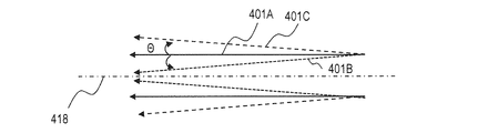
まず、発散角の定義を説明する。図4は発散角の定義を示す。図4において、レーザ光軸418と平行に進行するパルスレーザ光401Aを、発散角θ=0の平行光と定義する。レーザ光軸418に対して広がる方向に進行するパルスレーザ光401Cを、プラス発散角のパルスレーザ光と定義する。レーザ光軸418に対して狭まる方向に進行するパルスレーザ光401Bを、マイナス発散角のパルスレーザ光と定義する。なお、発散角θは半角で定義する。<Issues>
First, the definition of the divergence angle will be described. FIG. 4 shows the definition of the divergence angle. In FIG. 4, pulsed laser light 401A traveling in parallel with the laser
図5A〜図5Cは、ターゲット27における照射パルスレーザ光の集光状態による戻り光の状態を示す。図5A〜図5Cにおいて、実線矢印は照射パルスレーザ光を示し、破線矢印は戻り光を示す。図5A〜5Cは、最終段のビーム調節器345を例示し、ビーム調節器345に入射するパルスレーザ光は平行光とする。
FIGS. 5A to 5C show the state of the return light depending on the focused state of the irradiation pulse laser beam on the
図5Aは、パルスレーザ光の焦点413Aをターゲット位置に設定した場合の戻り光の状態を示す。パルスレーザ光の焦点413Aがターゲット位置に位置する状態を、ベストフォーカス状態とも呼ぶ。ビーム調節器345から出力されるパルスレーザ光411Aは、平行光であってもよい。ターゲット27はプラズマ化する前に表面反射によってパルスレーザ光を反射し得る。ターゲット27で反射されたパルスレーザ光は、戻り光となり得る。
FIG. 5A shows the state of the return light when the
パルスレーザ光の焦点をターゲット位置に設定した場合、戻り光は照射パルスレーザ光の光路をほぼ逆行し得る。ビーム調節器345へ入射する戻り光412Aは、平行光であり得る。さらに、戻り光は、上流側のパルスレーザ光の光路を構成する光学素子に入射し、光学素子を破損させ得る。特にレーザ装置3がマスタオシレータ(MO)と複数の増幅器(PA)を備えたMOPA構成の場合、上流側に行くほど光学素子のレーザ耐性は低くなり得る。この場合、増幅後の高出力レーザ光の一部である戻り光は、レーザ耐性の低い光学素子を破損させ得る。
When the focus of the pulse laser beam is set at the target position, the return light can substantially reverse the optical path of the irradiation pulse laser beam. The
図5Bは、パルスレーザ光の焦点413Bをターゲット位置より上流側に設定した場合の戻り光の状態を示す。パルスレーザ光の焦点413Bがターゲット位置より上流側に位置する状態を、上流側デフォーカス状態とも呼ぶ。ビーム調節器345から出力されるパルスレーザ光411Bは、マイナス発散角のパルスレーザ光であり得る。ターゲット27はプラズマ化する前に表面反射によってパルスレーザ光を反射し得る。ターゲット27で反射されたパルスレーザ光は、戻り光となり得る。
FIG. 5B shows the state of the return light when the
ビーム調節器345へ入射する戻り光412Bは、マイナス発散角のパルスレーザ光であり得る。マイナス発散角の戻り光は、上流側のパルスレーザ光の光路の途中で集光され得る。例えば戻り光は、レーザ光進行方向制御部34の光学素子の表面付近に集光されると、光学素子を破損させ得る。
The
図5Cは、パルスレーザ光の焦点413Cをターゲット位置より下流側に設定した場合の戻り光の状態を示す。パルスレーザ光の焦点413Cが、ターゲット位置より下流側に位置する状態を、下流側デフォーカス状態とも呼ぶ。ビーム調節器345から出力されるパルスレーザ光411Cは、プラス発散角のパルスレーザ光であり得る。ターゲット27はプラズマ化する前に表面反射によってパルスレーザ光を反射し得る。ターゲット27で反射されたパルスレーザ光は、戻り光となり得る。
FIG. 5C shows the state of the return light when the
ビーム調節器345へ入射する戻り光412Cは、プラス発散角のレーザ光であり得る。プラス発散角の戻り光は、拡散しながらパルスレーザ光の光路を逆行し、その過程でエネルギ密度が低下し得る。このため、上流側のレーザ光路を構成する光学素子が破損する可能性が非常に低くなり得る。
The return light 412C incident on the
図5Bに示す状態では、戻り光がレーザ光進行方向制御部34の途中で集光され得ることに加え、図5Aに示す状態に対して戻り光の光量が増大し得る。図5Dは、図5A及び図5Bにおける、ターゲット27へのパルスレーザ光照射状態を示す。図5Dにおいて、実線矢印は図5Bにおけるパルスレーザ光411Bを示し、破線矢印は図5Aにおけるパルスレーザ光411Aを示す。
In the state shown in FIG. 5B, the return light can be collected in the middle of the laser beam traveling
LPP方式のEUV光生成装置1は、ターゲット27の位置ばらつきを考慮して、パルスレーザ光をターゲット径に対して同等以上の径で照射するよう設計され得る。図5Dに示すパルスレーザ光411Aは、上記設計に対応する。これに対して、ビーム調節器345によってパルスレーザ光の焦点をターゲット位置より上流側に設定すると、図5Dに示すパルスレーザ光411Bの照射状態となり得る。
The LPP EUV
ターゲット27へのパルスレーザ光411Aおよびパルスレーザ光411Bの照射状態を、パルスレーザ光の進行方向(矢視F)から見て比較する。パルスレーザ光411Aの照射領域416Aの径は、パルスレーザ光411Aのスポット径415Aと一致し、ターゲット27の径よりわずかに大きくなり得る。そのため、パルスレーザ光411Aの一部はターゲット27に照射され得ない。
The irradiation states of the
一方、パルスレーザ光411Bの照射領域416Bの径は、ターゲット27の径より小さく、パルスレーザ光411Bの全てがターゲット27に照射され得る。レーザ光集光光学系22aに入射するパルスレーザ光411Bの径は、レーザ光集光光学系22aに入射するパルスレーザ光411Aの径に対して小さくなるため、スポット径415Bも小さくなり得る。これに伴って焦点深度も深くなるため、焦点413Bがパルスレーザ光上流側に位置しても、ターゲット位置においてパルスレーザ光411Bはパルスレーザ光411Aよりも小さな径で照射され得る。
On the other hand, the diameter of the
上述のように、図5Bにおけるパルスレーザ光411Bは、図5Aにおけるパルスレーザ光411Aに対して小さな径でターゲット27に照射され、ターゲット27に対する照射光量が増加し得る。したがって、パルスレーザ光がターゲット27に照射されて反射される割合が一定と仮定すると、図5Aにおけるパルスレーザ光照射状態よりも、図5Bにおけるパルスレーザ光照射状態の方が、戻り光の光量が多くなり得る。
As described above, the
発明者らは、図5A〜図5Cの状態を個別に実験し上記知見を得た。これにより以下の課題が明確となった。パルスレーザ光の焦点をターゲット位置に設定すると、ターゲット表面で反射されたパルスレーザ光が戻り光となってパルスレーザ光路を逆行し、上流の光学素子が破損し得る。パルスレーザ光の焦点をターゲット位置より上流側に設定すると、戻り光は伝送光学系を含む上流側のパルスレーザ光の光路の途中で集光され、たとえばレーザ光進行方向制御部34の光学素子が破損し得る。
The inventors obtained the above findings by individually experimenting with the states of FIGS. 5A to 5C. As a result, the following issues became clear. When the focal point of the pulse laser beam is set at the target position, the pulse laser beam reflected by the target surface becomes a return beam and travels backward in the pulse laser beam path, and the upstream optical element can be damaged. When the focal point of the pulse laser beam is set upstream from the target position, the return light is collected in the middle of the optical path of the upstream pulse laser beam including the transmission optical system. For example, the optical element of the laser beam traveling
5.実施形態1
<構成>
実施形態1のEUV光生成システム11は、図2に示す構成と同様の構成を有してもよい。5.
<Configuration>
The EUV light generation system 11 of
<動作>
図6A〜図6Cは、実施形態1におけるビーム伝送制御部349の動作のフローチャートを示す。ビーム伝送制御部349は、レーザ光進行方向制御部34の全ビーム調節器を、入射パルスレーザ光の発散角を保持したパルスレーザ光を出力する状態に設定してもよい。その後、ビーム伝送制御部349は、最終段のビーム調節器以外のビーム調節器それぞれを上流から調整し、平行光を出力する状態に設定してもよい。さらに、ビーム伝送制御部349は、最終段のビーム調節器を、下流側デフォーカス状態を実現するよう調整してもよい。<Operation>
6A to 6C are flowcharts showing the operation of the beam
具体的に説明する。図6Aを参照して、ビーム伝送制御部349は、レーザ光進行方向制御部34におけるビーム調節器について予め設定されているパラメータを読み込んでもよい(S101)。パラメータは、実験により決定され、不図示の記憶媒体に格納されていてもよい。読み込まれるパラメータは、ビーム調節器数N、フォーカス径D1〜DN−1、フォーカス径の許容値DT1〜DTN−1、デフォーカス径Dd、デフォーカス径の許容値DdTを含んでもよい。
This will be specifically described. Referring to FIG. 6A, the beam
ビーム調節器数Nは、レーザ光進行方向制御部34におけるビーム調節器の総数であってもよい。ビーム調節器の序数は、上流から下流に向かい1からNまで順に増加してもよい。
The number N of beam adjusters may be the total number of beam adjusters in the laser beam traveling
フォーカス径D1〜DN−1は、ビームモニタ348における、ビーム調節器1〜N−1それぞれの目標フォーカス径であってもよい。ビーム調節器1〜N−1それぞれを上流から調整する際、フォーカス径D1〜DN−1は、ビームモニタ348におけるビーム調節器1〜N−1それぞれの集光径を最小とするための、目標値であってもよい。
The focus diameters D1 to DN-1 may be target focus diameters of the
フォーカス径の許容値DT1〜DTN−1は、ビームモニタ348におけるビーム調節器1〜N−1それぞれの集光径を最小とするようにビーム調節器1〜N−1を調整する際の、許容値であってもよい。
The allowable values DT1 to DTN-1 of the focus diameter are the allowable values when adjusting the
デフォーカス径Ddは、パルスレーザ光の下流側デフォーカス状態を実現した際の、ビームモニタ348における目標デフォーカス径であってもよい。デフォーカス径の許容値DdTは、ビームモニタ348におけるビーム調節器Nのデフォーカス径の許容値であってもよい。
The defocus diameter Dd may be a target defocus diameter in the
次に、ビーム伝送制御部349は、ビーム調節器1〜Nそれぞれを初期化してもよい(S102〜S105)。具体的には、まず、ビーム伝送制御部349は、変数Kに1を代入してもよい(S102)。さらに、ビーム伝送制御部349は、ビーム調節器Kを初期化してもよい(S103)。具体的には、ビーム伝送制御部349は、ビーム調節器Kに平行光が入力した場合に平行光を出力するように、ビーム調節器Kを調整してもよい。調整後のビーム調節器Kは、入射パルスレーザ光の発散角を保持したパルスレーザ光を出力し得る。但し、レーザ装置3から出力されるレーザ光が平行光であるとは限らないので、あるビーム調節器と次段のビーム調節器との間、あるいはビーム調節器Kから出力されるレーザ光の発散角はプラスでもマイナスでもよい。
Next, the beam
次に、ビーム伝送制御部349は、変数Kをインクリメントしてもよい(S104)。変数Kの値がNでない場合(S105:N)、ビーム伝送制御部349は、ステップS103に戻ってもよい。変数Kの値がNである場合(S105:Y)、ビーム調節器1〜Nの初期化が終了し、ビーム伝送制御部349は、ステップS106に進んでもよい。
Next, the beam
ステップS106において、ビーム伝送制御部349は、EUV光生成制御部5を介してレーザ装置3を制御し、パルスレーザ光を出力させてもよい。このとき、ターゲット27は出力されなくてもよい。これにより、ターゲット27からの戻り光による光学素子の破損を避け得る。
In step S106, the beam
次に、ビーム伝送制御部349は、ビーム調節器1〜N−1のモニタ径がそれぞれフォーカス径D1〜DN−1となるよう、ビーム調節器1〜N−1を調整してもよい(S107〜S110)。本処理によりビーム調節器1〜N−1を、適正なビーム伝搬状態に調整し得る。適正なビーム伝搬状態とは、例えばビーム調節器1〜N−1それぞれから出力されるレーザ光がコリメート(平行光化)された状態であってもよい。あるいは、レーザ光のビームウエストが、あるビーム調節器と次段のビーム調節器との中間に位置する状態であってもよい。
Next, the beam
具体的には、ビーム伝送制御部349は、変数Kに1を代入してもよい(S107)。さらに、ビーム伝送制御部349は、ビームモニタ348によるモニタ径がフォーカス径DKとなるよう、ビーム調節器Kを調整してもよい(S108)。調整方法の詳細は、図6Bを参照して後述する。
Specifically, the beam
次に、ビーム伝送制御部349は、変数Kをインクリメントしてもよい(S109)。変数Kの値がN−1でない場合(S110:N)、ビーム伝送制御部349は、ステップS108に戻ってもよい。変数Kの値がN−1である場合(S110:Y)、ビーム調節器1〜N−1の調整が終了し、ビーム伝送制御部349は、ビーム調節器Nの調整(S111)に進んでもよい。
Next, the beam
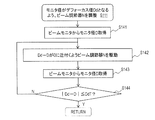
ステップS111において、ビーム伝送制御部349は、ビームモニタ348によるモニタ径がデフォーカス径Ddとなるよう、ビーム調節器Nを調整してもよい。調整方法の詳細は、図6Cを参照して後述する。本処理により調整されたビーム調節器Nの状態は、下流側デフォーカス状態であってもよい。ビーム調節器Nの調整が終了すると、ビーム伝送制御部349は、EUV光生成制御部5を介してレーザ装置3を制御し、パルスレーザ光を停止させてもよい(S112)。
In step S111, the beam
図6Bを参照して、ビーム調節器1〜N−1それぞれの調整方法(S108)を説明する。図6Bは、ステップS108の詳細のフローチャートを示す。まず、ビーム伝送制御部349は、ビームモニタ348から、測定されたモニタ径Dを取得してもよい(S121)。次に、ビーム伝送制御部349は、ビーム調節器Kのフォーカス径DKとモニタ径Dとの差分が0に近付くように、ビーム調節器Kを駆動してもよい(S122)。
With reference to FIG. 6B, the adjustment method (S108) of each of the
ビーム伝送制御部349は、ビームモニタ348から、測定されたモニタ径Dを取得してもよい(S123)。ビーム伝送制御部349は、ビーム調節器Kのフォーカス径DKとモニタ径Dとの差分の絶対値が、ビーム調節器Kのフォーカス径許容値DTK以下であるか判定してもよい(S124)。判定結果がNoの場合(S124:N)、ビーム伝送制御部349は、ステップS122に戻ってもよい。判定結果がYesの場合(S124:Y)、ビーム伝送制御部349は、本処理を終了してもよい。
The beam
次に、図6Cを参照して、ビーム調節器Nの調整方法(S111)を説明する。図6Cは、ステップS111の詳細のフローチャートを示す。まず、ビーム伝送制御部349は、ビームモニタ348から、測定されたモニタ径Dを取得してもよい(S141)。次に、ビーム伝送制御部349は、ビーム調節器Nのデフォーカス径Ddとモニタ径Dとの差分が0に近付くように、ビーム調節器Nを駆動してもよい(S142)。
Next, an adjustment method (S111) of the beam adjuster N will be described with reference to FIG. 6C. FIG. 6C shows a detailed flowchart of step S111. First, the beam
ビーム伝送制御部349は、ビームモニタ348から、測定されたモニタ径Dを取得してもよい(S143)。ビーム伝送制御部349は、ビーム調節器Nのデフォーカス径Ddとモニタ径Dとの差分の絶対値が、デフォーカス径許容値DdT以下であるか判定してもよい(S144)。判定結果がNoの場合(S144:N)、ビーム伝送制御部349は、ステップS142に戻ってもよい。判定結果がYesの場合(S144:Y)、ビーム伝送制御部349は、本処理を終了してもよい。
The beam
<効果>
実施形態1のEUV光生成システム11は、ビーム調節器を自動で下流側デフォーカス状態に調整し得るので、戻り光による光学素子の破損を抑制し得る。複数のビーム調節器を上流のビーム調節器から順次調整することで、迅速かつ適切な下流側デフォーカス状態を実現し得る。<Effect>
The EUV light generation system 11 according to the first embodiment can automatically adjust the beam adjuster to the downstream defocus state, and thus can prevent the optical element from being damaged by the return light. By sequentially adjusting the plurality of beam adjusters from the upstream beam adjuster, a quick and appropriate downstream defocus state can be realized.
ビーム調節器のモニタ径に基づく調整前に、入射光の発散角を維持する所定の状態に初期化することによって、その後の迅速かつ適切なビーム調節器それぞれの調整を実現し得る。また、最終段のビーム調節器の調整前に、上流のビーム調節器を適正なビーム伝搬状態に調整することで、最終段のビーム調節器の調整前に、パルスレーザ光焦点位置及び発散角を所定の状態に確定させ得る。これにより、最終段のビーム調節器を適切な下流側デフォーカス状態に容易に調整し得る。 Prior to the adjustment based on the monitor diameter of the beam conditioner, the subsequent adjustment of each beam conditioner can be realized quickly and appropriately by initializing to a predetermined state that maintains the divergence angle of the incident light. Also, by adjusting the upstream beam conditioner to an appropriate beam propagation state before adjusting the final stage beam conditioner, the focal position and divergence angle of the pulse laser beam can be adjusted before adjusting the last stage beam conditioner. A predetermined state can be established. As a result, the beam adjuster at the final stage can be easily adjusted to an appropriate downstream defocus state.
レーザ光進行方向制御部34の最終段のビーム調節器を下流側デフォーカス状態に調整することで、より確実にパルスレーザ光の適切な下流側デフォーカス状態を実現し得る。
By adjusting the beam adjuster at the final stage of the laser beam traveling
<他の構成例>
ビーム調節器の初期化ステップは省略してもよい。ビーム伝送制御部349は、レーザ光進行方向制御部34内の一部のビーム調節器のみをモニタ径に基づいて調整してもよい。<Other configuration examples>
The beam tuner initialization step may be omitted. The beam
例えば、ビーム伝送制御部349は、ビーム調節器345を、発散角度を変化させない初期化状態とし、ビーム調節器341、343をモニタ径に基づいて調整してもよい。調整されるビーム調節器341、343のうち最下流のビーム調節器343は、下流側デフォーカス状態に調整され、ビーム調節器341は、適正なビーム伝搬状態に調整されてもよい。あるいは、ビーム調節器341、345のように、ビーム伝送制御部349は、不連続の複数ビーム調節器を選択的に調整してもよい。
For example, the beam
レーザ光進行方向制御部34は、ビーム調節器341、343、345それぞれの直後に配置されたビームサンプラ及びビームサンプラそれぞれのサンプル光をモニタするビームモニタを含んでもよい。ビーム伝送制御部349は、ビーム調節器341、343、345の直後のサンプル光それぞれのモニタ径に基づいて、ビーム調節器341、343、345を調整してもよい。
The laser beam traveling
図6Cの処理(S111)は、EUV光生成中に実行されてもよい。これにより、EUV光生成中も下流側デフォーカス状態を維持し得る。レーザ装置3は、プリパルスレーザ光を出力するプリパルスレーザ装置と、メインパルスレーザ光を出力するメインパルスレーザ装置とを含んでもよい。
The process (S111) in FIG. 6C may be executed during EUV light generation. Thereby, the downstream defocus state can be maintained even during EUV light generation. The
EUV光生成システム11は、ターゲット27にプリパルスレーザ光を照射した後、メインパルスレーザ光を照射してもよい。この構成において、ビーム伝送制御部349は、プリパルスレーザ光路におけるビームデリバリシステムに対して上記処理を行ってもよい。
The EUV light generation system 11 may irradiate the
6.実施形態2
ビームモニタ348によるモニタ径がフォーカス径DKとなるようにビーム調節器Kを調整するステップS108において、集光されたサンプル光が、ビームモニタ348に入射し得る。一方、ビームモニタ348によるモニタ径がデフォーカス径Ddとなるようにビーム調節器Nを調整するステップS111において、ビームモニタ348に入射するサンプル光のエネルギ密度が低下し得る。このため、レーザ光進行方向制御部34は、ビームモニタ348における計測精度を向上させるための構成を備えてもよい。6). Embodiment 2
In step S108 in which the beam adjuster K is adjusted so that the monitor diameter of the
<構成>
図7は、実施形態2におけるレーザ光進行方向制御部34の構成例を示す。レーザ光進行方向制御部34は、サンプル光集光光学系347とビームモニタ348との間のサンプル光路にND(Neutral Density)フィルタ351を出入可能な、フィルタ挿入ステージ352を備えてもよい。NDフィルタ351は、サンプル光の波長域において略均等に、透過光量を低減し得る。<Configuration>
FIG. 7 shows a configuration example of the laser beam traveling
NDフィルタ351は、ビームスプリッタで置き換えてもよい。ビームスプリッタは、サンプル光路に対して傾斜して配置されてもよい。フィルタ挿入ステージ352は、ビーム伝送制御部349に接続されてもよい。
The
<動作>
図8は、実施形態2におけるビーム伝送制御部349の動作のフローチャートを示す。ビーム伝送制御部349は、ビーム調節器1〜N−1の調整において、NDフィルタ351をサンプル光路に挿入してもよい。ビーム伝送制御部349は、ビーム調節器Nの調整において、NDフィルタ351をサンプル光路から外してもよい。<Operation>
FIG. 8 shows a flowchart of the operation of the beam
具体的に説明する。ステップS201〜S206は、実施形態1の図6AにおけるステップS101〜S106と同様でもよい。ステップS207において、ビーム伝送制御部349は、フィルタ挿入ステージ352により、NDフィルタ351をサンプル光路に挿入してもよい。
This will be specifically described. Steps S201 to S206 may be the same as steps S101 to S106 in FIG. 6A of the first embodiment. In step S207, the beam
ステップS208〜S211は、図6AにおけるステップS107〜S110と同様でもよい。ステップS212において、ビーム伝送制御部349は、フィルタ挿入ステージ352により、NDフィルタ351をサンプル光路から外してもよい。ステップS213及びS214は、図6AにおけるステップS111及びS112と同様でもよい。
Steps S208 to S211 may be the same as steps S107 to S110 in FIG. 6A. In step S212, the beam
<効果>
実施形態2は、ビーム調節器1〜Nの調整において、ビームモニタに348入射するサンプル光のエネルギ密度変化を軽減し、ビームモニタ348における計測精度を向上させ得る。<Effect>
In the second embodiment, in the adjustment of the
<他の構成例>
サンプル光路に偏光素子と波長板を含む光学系を配置してもよく、レーザ光進行方向制御部34は、波長板を回転させる回転ステージを備えてよい。ビーム伝送制御部349は、サンプル光のエネルギ密度に応じて、波長板の回転角度を変更してもよい。<Other configuration examples>
An optical system including a polarizing element and a wave plate may be disposed in the sample optical path, and the laser beam traveling
サンプル光路に互いに透過偏光方向が直行する2つの偏光子を配置してよく、レーザ光進行方向制御部34は、いずれかの偏光子を回転させる回転ステージを備えてよい。ビーム伝送制御部349は、サンプル光のエネルギ密度に応じて、偏光子の回転角度を変更してもよい。
Two polarizers whose transmission polarization directions are perpendicular to each other may be arranged in the sample optical path, and the laser beam traveling
ビームモニタ348のゲインを変更できる場合、ビーム伝送制御部349は、サンプル光のエネルギ密度に応じて、ビームモニタ348のゲインを変更してもよい。ビーム伝送制御部349は、サンプル光のエネルギ密度が高い場合ゲインを下げ、エネルギ密度が低い場合にゲインを上げてもよい。
When the gain of the beam monitor 348 can be changed, the beam
ビーム伝送制御部349は、サンプル光のエネルギ密度に応じて、ビームモニタ348の画像取得積算回数を変更してもよい。ビーム伝送制御部349は、サンプル光のエネルギ密度が高い場合に積算回数を下げ、エネルギ密度が低い場合に積算回数を上げてもよい。ビームモニタ348は、光チョッパを内蔵してもよい。ビーム伝送制御部349は、サンプル光のエネルギ密度が高い場合にチョッパ回転数を上げ、エネルギ密度が低い場合にチョッパ回転数を下げてもよい。
The beam
7.実施形態3
<構成>
図9は、実施形態3におけるビーム調節器345の構成例を示す。ビーム調節器345は、移動プレート637の移動範囲を規制するための近接スイッチ639を備えてもよい。近接スイッチ639は、ビーム伝送制御部349に接続されてもよい。近接スイッチ639は、移動プレート637がデフォーカス位置からベストフォーカス位置の近傍に達すると、ビーム伝送制御部349に検出信号を出力するよう構成されてもよい。7).
<Configuration>
FIG. 9 shows a configuration example of the
<動作>
ビーム伝送制御部349が移動プレート637をデフォーカス位置からベストフォーカス位置に向かって移動すると、近接スイッチ639は、ベストフォーカス位置直前の規定位置において、検出信号を出力してもよい。検出信号はビーム伝送制御部349に送信されてもよい。ビーム伝送制御部349は、検出信号に従って移動プレート637を停止させてもよい。パルスレーザ光が出力されていない場合、ビーム伝送制御部349は近接スイッチ639からの検出信号を無視してもよい。近接スイッチ639は、誘導形、静電容量形、超音波形、光電形、磁気形等いずれのタイプのスイッチでもよい。<Operation>
When the
なお、同様の機能は、1軸移動ステージのエンコータからの出力値によって1軸移動ステージの移動範囲を制限するソフトウェアによって実現されてもよい。 A similar function may be realized by software that limits the movement range of the single-axis moving stage by the output value from the encoder of the single-axis moving stage.
<効果>
実施形態3は、EUV光生成中のビーム調節器の調整において、ビーム調節器がベストフォーカス状態となることを効果的に防止し得る。<Effect>
The third embodiment can effectively prevent the beam conditioner from being in the best focus state in the adjustment of the beam conditioner during EUV light generation.
8.その他の実施形態
ビーム調節器345の他の構成例を説明する。8). Other Embodiments Another configuration example of the
<他の構成例1>
図10は、ビーム調節器345の他の構成例を示す。他のビーム調節器341、343も、同様の構成を有してよい。ビーム調節器345は、変形可能な高反射面711と、高反射面711の背面に配置され、液体や気体等の媒質を収容する容器712と、を含んでもよい。高反射面711は、媒質の加圧状態において凸面を形成し、媒質の減圧状態において凹面を形成してもよい。容器712は、圧力調節器713に接続されてもよい。圧力調節器713は、ビーム伝送制御部349に接続されてもよい。<Other configuration example 1>
FIG. 10 shows another configuration example of the
ビーム調節器345は、圧力調節器713によって容器712に媒質を供給又は排出することによって、高反射面711への圧力を変化させてもよい。ビーム伝送制御部349は、圧力調節器713を介して高反射面711の背面への圧力を制御することによって、高反射面711を変形させ、発散角を調整してもよい。高反射面711には、ドライバーレーザ光が高反射する膜がコートされていてもよい。
The
<他の構成例2>
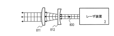
図11Aは、ビーム調節器345の他の構成例を示し、図11B〜図11Dは、その動作を示す。他のビーム調節器341、343も、同様の構成を有してよい。<Other configuration example 2>
FIG. 11A shows another configuration example of the
図11Aに示すように、ビーム調節器345は、レンズホルダ813に保持された球面凸レンズ811と、レンズホルダ814に保持された球面凹レンズ812と、を含んでもよい。レンズホルダ813及び814は、それぞれ、支持部815及び816によって支持されてもよい。支持部816は固定ステージ817に固定されてもよい。支持部815は、固定ステージ817上をスライドするスライダ819に固定されてもよい。ドライバ818は、ビーム伝送制御部349からの指示に従ってスライダ819を移動させてもよい。
As shown in FIG. 11A, the
球面凸レンズ811は焦点距離F1を有し、球面凹レンズ812は焦点距離F2を有してもよい。図11Aが示す状態において、球面凸レンズ811の焦点位置と球面凹レンズ812の焦点位置は、共焦点位置800において一致してもよい。
The spherical
図11Bに示す状態において、球面凸レンズ811の焦点位置と球面凹レンズ812の焦点位置は、共焦点位置800において一致してもよい。ビーム調節器345は、入射した平面波を、断面積が異なる平面波に変換してもよい。
In the state shown in FIG. 11B, the focal position of the spherical
図11Cに示すように、スライダ819は、図11Bに示す位置から下流側にスライドして、球面凸レンズ811を球面凹レンズ812から離れる方向に移動してもよい。球面凸レンズ811の焦点位置801は、球面凹レンズ812の焦点位置802よりも下流側に位置してよい。ビーム調節器345は、入射した平面波を凹面波に変換してもよい。
As shown in FIG. 11C, the
図11Dに示すように、スライダ819は、図11Bに示す位置から上流側にスライドして、球面凸レンズ811を球面凹レンズ812に近づく方向に移動してもよい。球面凸レンズ811の焦点位置801は、球面凹レンズ812の焦点位置802よりも上流側に位置してよい。ビーム調節器345は、入射した平面波を凸面波に変換してもよい。
As shown in FIG. 11D, the
上述のように、ビーム調節器345は、レーザ光の波面、レーザ光の断面積、ビームダイバージェンスを調節し得る。ビーム調節器345は、不図示の高反射ミラー及び当該高反射ミラーの角度を制御するアクチュエータをさらに含んでもよい。これにより、レーザ光の進行方向を制御し得る。
As described above, the
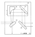
<他の構成例3>
図12は、ビーム調節器345の他の構成例を示す。他のビーム調節器341、343も、同様の構成を有してよい。ビーム調節器345は、軸外放物面凸面ミラー851、軸外放物面凹面ミラー852、平面ミラー853、平面ミラー854、ミラー固定プレート855、及び不図示の駆動機構、を含んでもよい。<Other configuration example 3>
FIG. 12 shows another configuration example of the
軸外放物面凸面ミラー851は、レーザ光が入射する位置に、不図示のミラーホルダによって固定されていてもよい。軸外放物面凸面ミラー851は、レーザ光を軸外放物面凹面ミラー852に向けて反射してもよい。
The off-axis paraboloidal
軸外放物面凸面ミラー851からの反射光は、軸外放物面凹面ミラー852の焦点の位置から放射した光と同等の波面を有する光と見なせる様に調整可能であってもよい。平面波が入射する場合、軸外放物面凸面ミラー851の焦点の位置と軸外放物面凹面ミラー852の焦点の位置とは同じであってもよい。
The reflected light from the off-axis paraboloid
軸外放物面凹面ミラー852は、軸外放物面凸面ミラー851によって反射されたレーザ光の光路に沿って移動できるように、不図示のミラーホルダを介してミラー固定プレート855に固定されていてもよい。軸外放物面凹面ミラー852は、軸外放物面凸面ミラー851によって反射されたレーザ光を平面ミラー853に向けて反射してもよい。
The off-axis paraboloid
平面ミラー853は、軸外放物面凹面ミラー852とともに移動できるように、不図示のミラーホルダを介してミラー固定プレート855に固定されていてもよい。平面ミラー853は、軸外放物面凹面ミラー852によって反射されたレーザ光を、平面ミラー854に向けて反射してもよい。
The
平面ミラー854は、平面ミラー853によって反射されたレーザ光の光路に、不図示のミラーホルダによって固定されていてもよい。平面ミラー854は、平面ミラー853によって反射されたレーザ光を、チャンバ2との間に配置された光学素子に向けて反射してもよい。
The
ミラー固定プレート855と、軸外放物面凸面ミラー851及び平面ミラー854との間隔が伸縮するように、ミラー固定プレート825が駆動機構によって紙面上下方向に移動させられてもよい。ミラー固定プレート825と軸外放物面凸面ミラー851及び平面ミラー854との間隔を伸縮させることにより、レーザ光のビーム断面積の大きさを調節し得る。
The mirror fixing plate 825 may be moved up and down by the drive mechanism so that the distance between the
上記の説明は、制限ではなく単なる例示を意図したものである。従って、添付の請求の範囲を逸脱することなく本開示の実施形態に変更を加えてもよいことは、当業者には明らかであろう。 The above description is intended to be illustrative only and not limiting. Thus, it will be apparent to one skilled in the art that modifications may be made to the embodiments of the present disclosure without departing from the scope of the appended claims.
ある実施形態の構成の一部を他の実施形態の構成に置き換え得る。ある実施形態の構成に他の実施形態の構成を加え得る。各実施形態の構成の一部について、削除、他の構成の追加、他の構成による置換をし得る。 A part of the configuration of one embodiment may be replaced with the configuration of another embodiment. The configuration of another embodiment can be added to the configuration of one embodiment. A part of the configuration of each embodiment may be deleted, added with another configuration, or replaced with another configuration.
本明細書及び添付の特許請求の範囲全体で使用される用語は、「限定的でない」用語と解釈されるべきである。例えば、「含む」又は「含まれる」という用語は、「含まれるものとして記載されたものに限定されない」と解釈されるべきである。「有する」という用語は、「有するものとして記載されたものに限定されない」と解釈されるべきである。また、本明細書及び添付の特許請求の範囲に記載される修飾句「1つの」は、「少なくとも1つ」又は「1又はそれ以上」を意味すると解釈されるべきである。 Terms used throughout this specification and the appended claims should be construed as "non-limiting" terms. For example, the terms “include” or “included” should be interpreted as “not limited to those described as included”. The term “comprising” should be interpreted as “not limited to what is described as having”. Also, the modifier “one” in the specification and the appended claims should be interpreted to mean “at least one” or “one or more”.
3 レーザ装置、11 EUV光生成システム、27 ターゲット、341、343、345 ビーム調節器、346 ビームサンプラ、348 ビームモニタ、349 ビーム伝送制御部、351 NDフィルタ、352 フィルタ挿入ステージ、639 近接スイッチ 3 laser device, 11 EUV light generation system, 27 target, 341, 343, 345 beam conditioner, 346 beam sampler, 348 beam monitor, 349 beam transmission control unit, 351 ND filter, 352 filter insertion stage, 639 proximity switch
Claims (10)
前記レーザ装置から出力されたパルスレーザ光の発散角を調節する複数のビーム調節器と、
前記複数のビーム調節器における最下流の第1ビーム調節器から出力されたパルスレーザ光の一部をサンプル光として分岐するビームサンプラと、
前記サンプル光を受光してモニタ径を出力するビームモニタと、
前記モニタ径に基づいて前記複数のビーム調節器を制御するビーム伝送制御部と、を含み、
前記ビーム伝送制御部は、
前記ビームモニタによるモニタ径が前記第1ビーム調節器以外の前記複数のビーム調節器それぞれに対応する所定値となるように、前記第1ビーム調節器以外の前記複数のビーム調節器それぞれを上流側から順次調整し、
パルスレーザ光がターゲット位置より下流に集光するように前記第1ビーム調節器を調整する、ビームデリバリシステム。In an extreme ultraviolet light generation device that generates extreme ultraviolet light by irradiating a target with pulsed laser light, a beam delivery system that transmits the pulsed laser light from the laser device toward the target,
A plurality of beam adjusters for adjusting the divergence angle of the pulsed laser light output from the laser device;
A beam sampler for branching a part of the pulsed laser light outputted from the first beam adjuster at the most downstream of the plurality of beam adjusters as a sample light;
A beam monitor that receives the sample light and outputs a monitor diameter;
A beam transmission control unit for controlling the plurality of beam adjusters based on the monitor diameter,
The beam transmission controller is
Each of the plurality of beam adjusters other than the first beam adjuster is arranged on the upstream side so that the monitor diameter by the beam monitor becomes a predetermined value corresponding to each of the plurality of beam adjusters other than the first beam adjuster. Adjust sequentially from
A beam delivery system that adjusts the first beam adjuster so that pulsed laser light is condensed downstream from a target position.
前記第1ビーム調節器は、前記ビームデリバリシステムにおける最終段ビーム調節器である、ビームデリバリシステム。The beam delivery system according to claim 1,
The beam delivery system, wherein the first beam conditioner is a final stage beam conditioner in the beam delivery system.
前記ビーム伝送制御部は、前記ビームモニタを使用した前記調整の前に、前記複数のビーム調節器それぞれを、平行光が入射した場合に平行光を出力するよう初期化する、ビームデリバリシステム。The beam delivery system according to claim 1,
The beam transmission control unit initializes each of the plurality of beam adjusters to output parallel light when parallel light is incident before the adjustment using the beam monitor.
前記第1ビーム調節器に対応する所定値は、前記複数のビーム調節器の他のビーム調節器に対応する所定値よりも大きく、
前記ビーム伝送制御部は、前記他のビーム調節器の調整において前記ビームモニタに入射するサンプル光の光量を、前記第1ビーム調節器の調整において前記ビームモニタに入射するサンプル光の光量よりも減少させる、ビームデリバリシステム。The beam delivery system according to claim 3,
A predetermined value corresponding to the first beam adjuster is greater than a predetermined value corresponding to another beam adjuster of the plurality of beam adjusters;
The beam transmission control unit reduces the light amount of the sample light incident on the beam monitor in the adjustment of the other beam adjuster than the light amount of the sample light incident on the beam monitor in the adjustment of the first beam adjuster. Let the beam delivery system.
前記第1ビーム調節器は、パルスレーザ光の集光位置がターゲット位置となる状態の近傍において検出信号を前記ビーム伝送制御部に出力し、
前記ビーム伝送制御部は、前記検出信号に応答して前記第1ビーム調節器の調整を停止する、ビームデリバリシステム。The beam delivery system according to claim 1,
The first beam adjuster outputs a detection signal to the beam transmission control unit in the vicinity of a state where the focused position of the pulse laser beam becomes the target position,
The beam transmission control unit stops the adjustment of the first beam adjuster in response to the detection signal.
レーザ装置からパルスレーザ光を出力させ、
前記複数のビーム調節器における最下流の第1ビーム調節器以外のビーム調節器を上流側から順次選択し、
選択したビーム調節器の下流においてサンプル光をモニタし、
前記サンプル光のモニタ径が前記選択したビーム調節器に対応する所定値となるよう、前記選択したビーム調節器を調整し、
パルスレーザ光がターゲット位置より下流に集光するように前記第1ビーム調節器を調整する、制御方法。A method for controlling a beam delivery system including a plurality of beam adjusters for adjusting a divergence angle of the pulse laser light in an extreme ultraviolet light generation apparatus that generates extreme ultraviolet light by irradiating a target with pulse laser light, ,
The pulse laser beam is output from the laser device,
Sequentially selecting beam adjusters other than the most downstream first beam adjuster in the plurality of beam adjusters from the upstream side;
Monitor the sample light downstream of the selected beam conditioner,
Adjusting the selected beam conditioner so that the monitor diameter of the sample light becomes a predetermined value corresponding to the selected beam conditioner;
A control method, wherein the first beam adjuster is adjusted so that pulsed laser light is condensed downstream from a target position.
前記第1ビーム調節器は、前記ビームデリバリシステムにおける最終段ビーム調節器である、制御方法。The control method according to claim 6, comprising:
The control method, wherein the first beam conditioner is a final stage beam conditioner in the beam delivery system.
前記モニタ径に基づいた前記調整の前に、前記複数のビーム調節器それぞれを、平行光が入射した場合に平行光を出力するよう調整する、制御方法。The control method according to claim 6, comprising:
A control method of adjusting each of the plurality of beam adjusters so as to output parallel light when parallel light is incident before the adjustment based on the monitor diameter.
前記第1ビーム調節器に対応する所定値は、前記複数のビーム調節器の他のビーム調節器に対応する所定値よりも大きく、
前記他のビーム調節器の調整において前記モニタ径を測定するビームモニタに入射するサンプル光の光量を、前記第1ビーム調節器の調整において前記ビームモニタに入射するサンプル光の光量よりも減少させる、制御方法。The control method according to claim 8, comprising:
A predetermined value corresponding to the first beam adjuster is greater than a predetermined value corresponding to another beam adjuster of the plurality of beam adjusters;
Reducing the amount of sample light incident on the beam monitor that measures the monitor diameter in the adjustment of the other beam adjuster to be less than the amount of sample light incident on the beam monitor in the adjustment of the first beam adjuster; Control method.
前記第1ビーム調節器から、パルスレーザ光の集光位置がターゲット位置となる状態の近傍において検出信号を受信し、
前記検出信号に応答して前記第1ビーム調節器の調整を停止する、制御方法。The control method according to claim 6, comprising:
From the first beam adjuster, a detection signal is received in the vicinity of a state where the focused position of the pulse laser beam becomes the target position,
A control method, wherein adjustment of the first beam adjuster is stopped in response to the detection signal.
Applications Claiming Priority (1)
| Application Number | Priority Date | Filing Date | Title |
|---|---|---|---|
| PCT/JP2015/053344 WO2016125295A1 (en) | 2015-02-06 | 2015-02-06 | Beam delivery system and control method therefor |
Publications (2)
| Publication Number | Publication Date |
|---|---|
| JPWO2016125295A1 JPWO2016125295A1 (en) | 2017-11-09 |
| JP6480960B2 true JP6480960B2 (en) | 2019-03-13 |
Family
ID=56563659
Family Applications (1)
| Application Number | Title | Priority Date | Filing Date |
|---|---|---|---|
| JP2016573151A Active JP6480960B2 (en) | 2015-02-06 | 2015-02-06 | Beam delivery system and control method thereof |
Country Status (3)
| Country | Link |
|---|---|
| US (1) | US10194515B2 (en) |
| JP (1) | JP6480960B2 (en) |
| WO (1) | WO2016125295A1 (en) |
Families Citing this family (5)
| Publication number | Priority date | Publication date | Assignee | Title |
|---|---|---|---|---|
| WO2016151682A1 (en) * | 2015-03-20 | 2016-09-29 | 国立大学法人 東京大学 | Euv light rotating ellipsoidal mirror reflectance measuring device |
| EP3695261B1 (en) | 2017-10-09 | 2023-06-07 | Nederlandse Organisatie voor toegepast- natuurwetenschappelijk onderzoek TNO | Refocusing device |
| EP3543760A1 (en) * | 2018-03-22 | 2019-09-25 | Nederlandse Organisatie voor toegepast- natuurwetenschappelijk onderzoek TNO | Refocusing device |
| JP7306888B2 (en) | 2019-06-13 | 2023-07-11 | ギガフォトン株式会社 | Extreme ultraviolet light generation system, laser beam size control method, and electronic device manufacturing method |
| JP7329422B2 (en) | 2019-11-18 | 2023-08-18 | ギガフォトン株式会社 | BEAM DELIVERY SYSTEM, FOCAL LENGTH SELECTION METHOD, AND ELECTRONIC DEVICE MANUFACTURING METHOD |
Family Cites Families (10)
| Publication number | Priority date | Publication date | Assignee | Title |
|---|---|---|---|---|
| JP2000357835A (en) | 1999-06-15 | 2000-12-26 | Amada Eng Center Co Ltd | Laser oscillator |
| JP2003347236A (en) | 2002-05-28 | 2003-12-05 | Sony Corp | Laser irradiation device |
| JP4875879B2 (en) | 2005-10-12 | 2012-02-15 | 株式会社小松製作所 | Initial alignment method of extreme ultraviolet light source device |
| JP4932592B2 (en) | 2007-05-14 | 2012-05-16 | 株式会社小松製作所 | Extreme ultraviolet light source device |
| JP5833806B2 (en) | 2008-09-19 | 2015-12-16 | ギガフォトン株式会社 | Extreme ultraviolet light source device, laser light source device for extreme ultraviolet light source device, and adjustment method of laser light source for extreme ultraviolet light source device |
| JP5368261B2 (en) | 2008-11-06 | 2013-12-18 | ギガフォトン株式会社 | Extreme ultraviolet light source device, control method of extreme ultraviolet light source device |
| JP5816440B2 (en) * | 2011-02-23 | 2015-11-18 | ギガフォトン株式会社 | Optical device, laser device, and extreme ultraviolet light generator |
| EP2546634B1 (en) | 2011-07-14 | 2019-04-17 | SCREEN Holdings Co., Ltd. | Inspection apparatus and inspection method |
| DE102012217520A1 (en) * | 2012-09-27 | 2014-03-27 | Trumpf Laser- Und Systemtechnik Gmbh | Beam guiding device and method for adjusting the opening angle of a laser beam |
| TWI611731B (en) * | 2012-12-21 | 2018-01-11 | Gigaphoton Inc | Laser beam control device and extreme ultraviolet light generating device |
-
2015
- 2015-02-06 WO PCT/JP2015/053344 patent/WO2016125295A1/en active Application Filing
- 2015-02-06 JP JP2016573151A patent/JP6480960B2/en active Active
-
2017
- 2017-06-05 US US15/613,789 patent/US10194515B2/en active Active
Also Published As
| Publication number | Publication date |
|---|---|
| US20170280544A1 (en) | 2017-09-28 |
| US10194515B2 (en) | 2019-01-29 |
| WO2016125295A1 (en) | 2016-08-11 |
| JPWO2016125295A1 (en) | 2017-11-09 |
Similar Documents
| Publication | Publication Date | Title |
|---|---|---|
| US9574935B2 (en) | System for generating extreme ultra violet light | |
| US9128391B2 (en) | Optical device including wavefront correction parts and beam direction parts, laser apparatus including the optical device, and extreme ultraviolet light generation system including the laser apparatus | |
| JP5368261B2 (en) | Extreme ultraviolet light source device, control method of extreme ultraviolet light source device | |
| JP5846572B2 (en) | Chamber apparatus, extreme ultraviolet light generation apparatus, and control method of extreme ultraviolet light generation apparatus | |
| JP6480960B2 (en) | Beam delivery system and control method thereof | |
| US9363878B2 (en) | Device for controlling laser beam and apparatus for generating extreme ultraviolet light utilizing wavefront adjusters | |
| US10027084B2 (en) | Alignment system and extreme ultraviolet light generation system | |
| US9167679B2 (en) | Beam position control for an extreme ultraviolet light source | |
| US20130037693A1 (en) | Optical system and extreme ultraviolet (euv) light generation system including the optical system | |
| JP2012510156A (en) | System and method for driving laser beam delivery in an EUV light source | |
| WO2016135965A1 (en) | Beam dump device, laser device provided with same, and extreme ultraviolet light generation device | |
| JP5711326B2 (en) | Extreme ultraviolet light generator | |
| WO2016098240A1 (en) | Extreme ultraviolet light generation device | |
| JP7329422B2 (en) | BEAM DELIVERY SYSTEM, FOCAL LENGTH SELECTION METHOD, AND ELECTRONIC DEVICE MANUFACTURING METHOD | |
| JP2016154156A (en) | Extreme ultraviolet light generation device | |
| JP6232462B2 (en) | Alignment system | |
| US11828952B2 (en) | Light source and extreme ultraviolet light source system using the same | |
| WO2014119200A1 (en) | Mirror device |
Legal Events
| Date | Code | Title | Description |
|---|---|---|---|
| A621 | Written request for application examination |
Free format text: JAPANESE INTERMEDIATE CODE: A621 Effective date: 20180104 |
|
| TRDD | Decision of grant or rejection written | ||
| A01 | Written decision to grant a patent or to grant a registration (utility model) |
Free format text: JAPANESE INTERMEDIATE CODE: A01 Effective date: 20190122 |
|
| A61 | First payment of annual fees (during grant procedure) |
Free format text: JAPANESE INTERMEDIATE CODE: A61 Effective date: 20190208 |
|
| R150 | Certificate of patent or registration of utility model |
Ref document number: 6480960 Country of ref document: JP Free format text: JAPANESE INTERMEDIATE CODE: R150 |
|
| R250 | Receipt of annual fees |
Free format text: JAPANESE INTERMEDIATE CODE: R250 |
|
| R250 | Receipt of annual fees |
Free format text: JAPANESE INTERMEDIATE CODE: R250 |
|
| R250 | Receipt of annual fees |
Free format text: JAPANESE INTERMEDIATE CODE: R250 |