JP6479407B2 - Radiation thermometer and temperature measurement method - Google Patents
Radiation thermometer and temperature measurement method Download PDFInfo
- Publication number
- JP6479407B2 JP6479407B2 JP2014213906A JP2014213906A JP6479407B2 JP 6479407 B2 JP6479407 B2 JP 6479407B2 JP 2014213906 A JP2014213906 A JP 2014213906A JP 2014213906 A JP2014213906 A JP 2014213906A JP 6479407 B2 JP6479407 B2 JP 6479407B2
- Authority
- JP
- Japan
- Prior art keywords
- light
- wavelength range
- temperature
- measurement
- predetermined wavelength
- Prior art date
- Legal status (The legal status is an assumption and is not a legal conclusion. Google has not performed a legal analysis and makes no representation as to the accuracy of the status listed.)
- Active
Links
- 230000005855 radiation Effects 0.000 title claims description 118
- 238000000034 method Methods 0.000 title claims description 19
- 238000009529 body temperature measurement Methods 0.000 title description 20
- 238000005259 measurement Methods 0.000 claims description 150
- 238000000295 emission spectrum Methods 0.000 claims description 38
- 239000000758 substrate Substances 0.000 claims description 32
- 238000001228 spectrum Methods 0.000 claims description 24
- 230000003287 optical effect Effects 0.000 claims description 18
- 238000004519 manufacturing process Methods 0.000 claims description 13
- 239000004065 semiconductor Substances 0.000 claims description 13
- 238000004364 calculation method Methods 0.000 claims description 9
- 230000001678 irradiating effect Effects 0.000 claims description 2
- 238000010438 heat treatment Methods 0.000 claims 2
- 239000010408 film Substances 0.000 description 40
- 239000010409 thin film Substances 0.000 description 22
- 230000007423 decrease Effects 0.000 description 12
- JMASRVWKEDWRBT-UHFFFAOYSA-N Gallium nitride Chemical compound [Ga]#N JMASRVWKEDWRBT-UHFFFAOYSA-N 0.000 description 10
- 229910002601 GaN Inorganic materials 0.000 description 8
- 230000015572 biosynthetic process Effects 0.000 description 8
- 238000012937 correction Methods 0.000 description 6
- 239000000463 material Substances 0.000 description 6
- XUIMIQQOPSSXEZ-UHFFFAOYSA-N Silicon Chemical compound [Si] XUIMIQQOPSSXEZ-UHFFFAOYSA-N 0.000 description 4
- 150000001875 compounds Chemical class 0.000 description 4
- 238000012821 model calculation Methods 0.000 description 4
- 238000002310 reflectometry Methods 0.000 description 4
- 229910052710 silicon Inorganic materials 0.000 description 4
- 239000010703 silicon Substances 0.000 description 4
- PFNQVRZLDWYSCW-UHFFFAOYSA-N (fluoren-9-ylideneamino) n-naphthalen-1-ylcarbamate Chemical compound C12=CC=CC=C2C2=CC=CC=C2C1=NOC(=O)NC1=CC=CC2=CC=CC=C12 PFNQVRZLDWYSCW-UHFFFAOYSA-N 0.000 description 2
- 230000005457 Black-body radiation Effects 0.000 description 2
- 238000007796 conventional method Methods 0.000 description 2
- 239000013078 crystal Substances 0.000 description 2
- 238000011156 evaluation Methods 0.000 description 2
- 230000010355 oscillation Effects 0.000 description 2
- PIGFYZPCRLYGLF-UHFFFAOYSA-N Aluminum nitride Chemical compound [Al]#N PIGFYZPCRLYGLF-UHFFFAOYSA-N 0.000 description 1
- JBRZTFJDHDCESZ-UHFFFAOYSA-N AsGa Chemical compound [As]#[Ga] JBRZTFJDHDCESZ-UHFFFAOYSA-N 0.000 description 1
- 229910052581 Si3N4 Inorganic materials 0.000 description 1
- VYPSYNLAJGMNEJ-UHFFFAOYSA-N Silicium dioxide Chemical compound O=[Si]=O VYPSYNLAJGMNEJ-UHFFFAOYSA-N 0.000 description 1
- 238000013459 approach Methods 0.000 description 1
- 230000005540 biological transmission Effects 0.000 description 1
- 230000004397 blinking Effects 0.000 description 1
- 238000005229 chemical vapour deposition Methods 0.000 description 1
- 239000000470 constituent Substances 0.000 description 1
- 238000009826 distribution Methods 0.000 description 1
- 230000000694 effects Effects 0.000 description 1
- 229910052732 germanium Inorganic materials 0.000 description 1
- GNPVGFCGXDBREM-UHFFFAOYSA-N germanium atom Chemical compound [Ge] GNPVGFCGXDBREM-UHFFFAOYSA-N 0.000 description 1
- 229910052736 halogen Inorganic materials 0.000 description 1
- 150000002367 halogens Chemical class 0.000 description 1
- 229910052738 indium Inorganic materials 0.000 description 1
- APFVFJFRJDLVQX-UHFFFAOYSA-N indium atom Chemical compound [In] APFVFJFRJDLVQX-UHFFFAOYSA-N 0.000 description 1
- 230000031700 light absorption Effects 0.000 description 1
- 229910052751 metal Inorganic materials 0.000 description 1
- 239000002184 metal Substances 0.000 description 1
- 238000012986 modification Methods 0.000 description 1
- 230000004048 modification Effects 0.000 description 1
- 150000004767 nitrides Chemical class 0.000 description 1
- 238000000255 optical extinction spectrum Methods 0.000 description 1
- 239000002994 raw material Substances 0.000 description 1
- 229910052594 sapphire Inorganic materials 0.000 description 1
- 239000010980 sapphire Substances 0.000 description 1
- 238000000926 separation method Methods 0.000 description 1
- HQVNEWCFYHHQES-UHFFFAOYSA-N silicon nitride Chemical compound N12[Si]34N5[Si]62N3[Si]51N64 HQVNEWCFYHHQES-UHFFFAOYSA-N 0.000 description 1
- 229910052814 silicon oxide Inorganic materials 0.000 description 1
- 238000004544 sputter deposition Methods 0.000 description 1
- 238000000411 transmission spectrum Methods 0.000 description 1
- 238000007740 vapor deposition Methods 0.000 description 1
Images


Classifications
-
- G—PHYSICS
- G01—MEASURING; TESTING
- G01J—MEASUREMENT OF INTENSITY, VELOCITY, SPECTRAL CONTENT, POLARISATION, PHASE OR PULSE CHARACTERISTICS OF INFRARED, VISIBLE OR ULTRAVIOLET LIGHT; COLORIMETRY; RADIATION PYROMETRY
- G01J5/00—Radiation pyrometry, e.g. infrared or optical thermometry
- G01J5/02—Constructional details
- G01J5/08—Optical arrangements
- G01J5/0801—Means for wavelength selection or discrimination
- G01J5/0802—Optical filters
-
- G—PHYSICS
- G01—MEASURING; TESTING
- G01J—MEASUREMENT OF INTENSITY, VELOCITY, SPECTRAL CONTENT, POLARISATION, PHASE OR PULSE CHARACTERISTICS OF INFRARED, VISIBLE OR ULTRAVIOLET LIGHT; COLORIMETRY; RADIATION PYROMETRY
- G01J5/00—Radiation pyrometry, e.g. infrared or optical thermometry
- G01J5/0003—Radiation pyrometry, e.g. infrared or optical thermometry for sensing the radiant heat transfer of samples, e.g. emittance meter
- G01J5/0007—Radiation pyrometry, e.g. infrared or optical thermometry for sensing the radiant heat transfer of samples, e.g. emittance meter of wafers or semiconductor substrates, e.g. using Rapid Thermal Processing
-
- G—PHYSICS
- G01—MEASURING; TESTING
- G01J—MEASUREMENT OF INTENSITY, VELOCITY, SPECTRAL CONTENT, POLARISATION, PHASE OR PULSE CHARACTERISTICS OF INFRARED, VISIBLE OR ULTRAVIOLET LIGHT; COLORIMETRY; RADIATION PYROMETRY
- G01J5/00—Radiation pyrometry, e.g. infrared or optical thermometry
- G01J5/02—Constructional details
- G01J5/08—Optical arrangements
- G01J5/0896—Optical arrangements using a light source, e.g. for illuminating a surface
-
- G—PHYSICS
- G01—MEASURING; TESTING
- G01J—MEASUREMENT OF INTENSITY, VELOCITY, SPECTRAL CONTENT, POLARISATION, PHASE OR PULSE CHARACTERISTICS OF INFRARED, VISIBLE OR ULTRAVIOLET LIGHT; COLORIMETRY; RADIATION PYROMETRY
- G01J5/00—Radiation pyrometry, e.g. infrared or optical thermometry
- G01J5/60—Radiation pyrometry, e.g. infrared or optical thermometry using determination of colour temperature
- G01J5/602—Radiation pyrometry, e.g. infrared or optical thermometry using determination of colour temperature using selective, monochromatic or bandpass filtering
-
- G—PHYSICS
- G01—MEASURING; TESTING
- G01J—MEASUREMENT OF INTENSITY, VELOCITY, SPECTRAL CONTENT, POLARISATION, PHASE OR PULSE CHARACTERISTICS OF INFRARED, VISIBLE OR ULTRAVIOLET LIGHT; COLORIMETRY; RADIATION PYROMETRY
- G01J5/00—Radiation pyrometry, e.g. infrared or optical thermometry
- G01J5/80—Calibration
- G01J5/802—Calibration by correcting for emissivity
Landscapes
- Physics & Mathematics (AREA)
- General Physics & Mathematics (AREA)
- Spectroscopy & Molecular Physics (AREA)
- Radiation Pyrometers (AREA)
Description
本発明は、放射温度計及び温度測定方法に関する。 The present invention relates to a radiation thermometer and a temperature measurement method.
放射温度計は、測定対象物から放射される熱輻射強度(熱放射強度)を測定して測定対象物の温度を求めるものである。この放射温度計は、測定対象物に非接触で、比較的短い時間で測定対象の温度を測定できるという特徴を有するため、工業的な価値が大きい。とくに、温度や圧力、雰囲気などを外界と大きく異なる条件にした状況下にある測定対象物の温度を測定する場合には、前述の特徴が有効に発揮される。さらに、測定対象物が移動する場合には、非接触式であるという放射温度計の特徴が重要となる。 The radiation thermometer measures the thermal radiation intensity (thermal radiation intensity) radiated from the measurement object and obtains the temperature of the measurement object. Since this radiation thermometer has the characteristic that the temperature of the measurement object can be measured in a relatively short time without contact with the measurement object, it has a great industrial value. In particular, when measuring the temperature of an object to be measured under conditions in which the temperature, pressure, atmosphere, and the like are greatly different from those of the outside world, the above-described characteristics are effectively exhibited. Further, when the measurement object moves, the feature of the radiation thermometer that is non-contact type becomes important.
放射温度計が用いられている工業的な応用の例としては、半導体の製造や窒化物系を含む化合物半導体の製造などが挙げられる。高い純度で高品質の半導体を製造するためには、製造装置の内部を外部から隔離し、製造装置の内部に保持した基板を高温に加熱する場合がほとんどである。とくに、化学的に活性な原料ガスに晒して基板上に成膜を行う有機金属化学気相成長法(MOCVD:MetalOrganic Chemical Vapor Deposition)、あるいは、高真空中で半導体の構成元素を蒸発させて基板上に成膜させる分子ビームエピタキシャル法(MBE:Molecular Beam Epitaxy)がよく知られている。 Examples of industrial applications in which a radiation thermometer is used include the manufacture of semiconductors and the manufacture of compound semiconductors including nitrides. In order to manufacture a high-quality semiconductor with high purity, the inside of the manufacturing apparatus is often isolated from the outside, and the substrate held inside the manufacturing apparatus is heated to a high temperature. In particular, a metal organic chemical vapor deposition (MOCVD) method in which a film is formed on a substrate by exposure to a chemically active source gas, or a constituent element of a semiconductor is evaporated in a high vacuum. A molecular beam epitaxial method (MBE) for forming a film thereon is well known.
これらの半導体製造装置については、製造される半導体の均一性や再現性を良好に保つために、非常に精密な温度計測が求められる。具体例としては、測定対象物の温度が600℃から1200℃の範囲で、測定精度が±2℃あるいはそれ以下である。実際に、InGaN(窒化インジウムガリウム)とGaN(窒化ガリウム)で構成される多重量子井戸を発光層とする発光素子の製造においては、この発光層の製造過程で基板はおおむね700℃から800℃の範囲内で他の製造条件から決まる特定の温度に保持されている。この特定の温度が発光素子の発光波長に大きく影響するため、高い発光波長均一性および再現性を実現するためには上記に述べたような精密な温度計測が必要となる。 With respect to these semiconductor manufacturing apparatuses, very precise temperature measurement is required in order to keep the uniformity and reproducibility of the semiconductors manufactured. As a specific example, the temperature of the measurement object is in the range of 600 ° C. to 1200 ° C., and the measurement accuracy is ± 2 ° C. or less. Actually, in the manufacture of a light emitting device having a multiple quantum well composed of InGaN (indium gallium nitride) and GaN (gallium nitride) as a light emitting layer, the substrate is generally at 700 to 800 ° C. in the process of manufacturing the light emitting layer. It is maintained at a specific temperature within a range determined by other manufacturing conditions. Since this specific temperature greatly affects the light emission wavelength of the light emitting element, precise temperature measurement as described above is required to achieve high light emission wavelength uniformity and reproducibility.
一方、放射温度計を用いて測定対象物の温度を正確に測定するためには、測定対象物の放射率の値が必要である。物体の温度が上昇するにつれて物体からの熱輻射強度は増大するため、物体からの熱輻射強度を測定することで物体の温度を計測することが可能である。ただし、一般の物体からの熱輻射強度は同じ温度の黒体からの熱輻射強度に比べて小さい。ある温度の物体からの熱輻射強度を同じ温度にある黒体からの熱輻射の強度で割ったものが放射率である。したがって、物体からの熱輻射強度を測定し、この熱輻射強度をその物体の放射率で割ることで、この物体と同じ温度の黒体が放射する熱輻射の強度を求め、この熱輻射強度から物体の温度を計算することができる。ここで述べた原理を用いた放射温度計は、広い温度範囲での黒体を用いた較正を行うことなしに、放射温度計から測定対象までのさまざまな構成の光学部品の変更に対して、適切な温度での較正を行うことで対応が可能である。 On the other hand, in order to accurately measure the temperature of the measurement object using the radiation thermometer, the emissivity value of the measurement object is required. Since the heat radiation intensity from the object increases as the temperature of the object rises, it is possible to measure the temperature of the object by measuring the heat radiation intensity from the object. However, the heat radiation intensity from a general object is smaller than the heat radiation intensity from a black body at the same temperature. The emissivity is obtained by dividing the heat radiation intensity from an object at a certain temperature by the intensity of heat radiation from a black body at the same temperature. Therefore, by measuring the thermal radiation intensity from the object and dividing this thermal radiation intensity by the emissivity of the object, the intensity of the thermal radiation emitted by the black body at the same temperature as this object is obtained, and from this thermal radiation intensity The temperature of the object can be calculated. Radiation thermometers using the principle described here are suitable for changing optical components of various configurations from radiation thermometers to measurement objects without performing calibration using black bodies over a wide temperature range. This can be done by calibrating at an appropriate temperature.
放射率はさまざまな材料で測定されており、各種文献などで公表されている。一般に放射温度計は放射率を記憶しておき、これを用いて物体からの熱輻射の強度を補正できる機能を持っているものが多く、測定対象物の材料の放射率が文献値などでわかっていれば、これを放射温度計に記憶させて用いることができる。ただし、放射率は、測定対象物の材質だけでなく、表面状態や温度などにも依存する。この意味で、公表されている放射率は精密な温度測定に用いることは難しい。 The emissivity is measured with various materials and published in various literatures. In general, radiation thermometers have a function that can store the emissivity and use it to correct the intensity of heat radiation from the object. If so, it can be stored in a radiation thermometer for use. However, the emissivity depends not only on the material of the object to be measured but also on the surface condition and temperature. In this sense, the published emissivity is difficult to use for precise temperature measurements.
一方、ある限定された条件下では、放射率を測定することが可能である。つまり、熱輻射強度を測定するための光の波長範囲において、測定対象物を光が透過せず、また測定対象物の表面に照射した光が散乱されない場合、測定対象物の表面での光の反射率をRとすると、放射率(ε)は、ε=1−Rという式で表わされる。したがって、熱輻射強度を測定する光の波長範囲において、測定対象物の表面が十分な鏡面性を有し、外部からの光源を用いて測定対象物の反射率を測定することが可能であり、測定対象物が光を吸収する場合には、測定対象物の表面状態や温度にかかわらず放射率を求めることができる。このような方法を用いて精度良く測定対象物の温度を測定するためには、あらかじめ設定された波長で測定対象物からの熱輻射の強度及び反射率を正確に求めることが重要である。 On the other hand, under certain limited conditions, it is possible to measure emissivity. In other words, in the light wavelength range for measuring the heat radiation intensity, when light does not pass through the measurement object and the light irradiated on the surface of the measurement object is not scattered, the light on the surface of the measurement object When the reflectance is R, the emissivity (ε) is expressed by the equation ε = 1−R. Therefore, in the wavelength range of the light for measuring the heat radiation intensity, the surface of the measurement object has sufficient specularity, and it is possible to measure the reflectance of the measurement object using an external light source, When the measurement object absorbs light, the emissivity can be obtained regardless of the surface state and temperature of the measurement object. In order to accurately measure the temperature of the measurement object using such a method, it is important to accurately obtain the intensity and reflectance of the heat radiation from the measurement object at a preset wavelength.
前述のように測定対象物の放射率を求めながら温度を測定する放射温度計は、基板上に薄膜を形成する場合の基板温度測定にとくに重要である。基板上に薄膜を形成する過程では、薄膜により光の干渉が生じることで、薄膜を含む基板の放射率は成膜が進む(膜が厚くなる)につれて絶えず変化する。この放射率の変化により、たとえ測定対象物の温度が一定であっても、測定対象物からの熱輻射の強度は変化する。このような場合であっても、前述のような条件が満たされている場合には、外部からの光源を用いて適切に反射率を測定することで、放射率の補正を行うことができる。 A radiation thermometer that measures temperature while obtaining the emissivity of an object to be measured as described above is particularly important for measuring the substrate temperature when a thin film is formed on the substrate. In the process of forming a thin film on the substrate, light interference occurs in the thin film, and the emissivity of the substrate including the thin film constantly changes as the film formation proceeds (the film becomes thicker). Due to this change in emissivity, the intensity of heat radiation from the measurement object changes even if the temperature of the measurement object is constant. Even in such a case, when the above-described conditions are satisfied, the emissivity can be corrected by appropriately measuring the reflectance using an external light source.
しかしながら、熱輻射強度の測定における信号の雑音を低減するためには、熱輻射強度を測定する光の波長範囲を広くし、検出器で検出される光強度を大きくする必要がある。例えば、中心波長が950nmで選択波長範囲が±25nmの波長選択フィルタを用いた場合には(波長範囲の幅=50nm)、同じ中心波長で波長範囲が±5nm(波長範囲の幅=10nm)の場合に比べて、単純に5倍の信号強度が期待される。このように大きな信号強度を得ることにより、熱輻射強度が小さくなる低温での温度測定が可能になり、測定温度の下限を下げることができる。あるいは、短時間に十分な信号強度を得ることが可能となり、より高速の温度測定ができるようになる。 However, in order to reduce signal noise in the measurement of the heat radiation intensity, it is necessary to widen the wavelength range of the light for measuring the heat radiation intensity and increase the light intensity detected by the detector. For example, when a wavelength selection filter having a center wavelength of 950 nm and a selection wavelength range of ± 25 nm is used (wavelength range width = 50 nm), the wavelength range is ± 5 nm (wavelength range width = 10 nm) at the same center wavelength. Compared to the case, a signal strength of 5 times is simply expected. By obtaining such a large signal intensity, temperature measurement at a low temperature where the heat radiation intensity becomes small becomes possible, and the lower limit of the measurement temperature can be lowered. Alternatively, sufficient signal intensity can be obtained in a short time, and higher-speed temperature measurement can be performed.
一方で、上記の熱輻射強度を測定する波長の範囲の上限についてはおもに2つの要因が考えられる。第1の要因は、熱輻射による発光エネルギーが波長依存性を持つことによる。この波長依存性は測定対象の温度により異なる。黒体の温度が1200℃以下の場合、近赤外より短波長の波長領域では、波長が短くになるにしたがい、発光エネルギーが小さくなる。したがって、ある波長範囲で熱輻射を観測して、その観測値から、黒体輻射の式を用いて温度を計算すると誤差が生じる。具体例を図13に示す。図13は熱輻射を測定する波長範囲が、上限を1000nmとし、下限を変化させて、測定波長範囲の熱輻射強度から黒体輻射の式を用いて温度を計算したものである。較正温度は1000℃、測定対象の温度は600℃である。図13から熱輻射強度を測定する波長の下限が900nm(波長範囲は100nm)では温度の誤差が2℃程度であること、波長の下限が短くなる(波長範囲が大きくなる)にしたがい誤差が大きくなることがわかる。600℃での測定温度の誤差を10℃以内にするためには波長の下限は800nm(波長範囲は200nm)である。第1の要因による測定温度の誤差は、熱輻射強度の測定波長範囲と、測定対象の温度により決まる。もし第1の要因しか生じない場合には、測定された温度をもとに温度制御をしても、絶対値に誤差はあるものの、安定した制御が可能であり、再現性もよい。 On the other hand, two factors can be considered for the upper limit of the wavelength range for measuring the heat radiation intensity. The first factor is due to the fact that the light emission energy due to thermal radiation has wavelength dependency. This wavelength dependency varies depending on the temperature of the object to be measured. When the temperature of the black body is 1200 ° C. or lower, the emission energy decreases as the wavelength becomes shorter in the wavelength region shorter than the near infrared. Therefore, if thermal radiation is observed in a certain wavelength range and the temperature is calculated from the observed value using the blackbody radiation equation, an error occurs. A specific example is shown in FIG. In FIG. 13, the wavelength range for measuring the heat radiation is calculated by using the black body radiation equation from the heat radiation intensity in the measurement wavelength range with the upper limit being 1000 nm and the lower limit being changed. The calibration temperature is 1000 ° C., and the temperature to be measured is 600 ° C. From FIG. 13, when the lower limit of the wavelength for measuring the heat radiation intensity is 900 nm (the wavelength range is 100 nm), the temperature error is about 2 ° C., and the error becomes larger as the lower limit of the wavelength becomes shorter (the wavelength range becomes larger). I understand that In order to make the measurement temperature error at 600 ° C. within 10 ° C., the lower limit of the wavelength is 800 nm (the wavelength range is 200 nm). The measurement temperature error due to the first factor is determined by the measurement wavelength range of the heat radiation intensity and the temperature of the measurement target. If only the first factor occurs, even if temperature control is performed based on the measured temperature, there is an error in the absolute value, but stable control is possible and reproducibility is good.
第2の要因は基板上に薄膜を成膜することによる放射率の変化によるものである。選択波長範囲が広くなると、とくに基板上に形成される薄膜において選択波長範囲内での光吸収が小さい場合には、その薄膜の厚みが大きくなるにつれて、熱輻射強度を測定する波長範囲内での干渉の影響が無視できなくなる。具体的には、選択された波長範囲での熱輻射強度の波長分布がおおむね一定とみなされる場合よりも大きく変化することになり、選択波長範囲内で観測される熱輻射強度が中心波長における熱輻射強度を忠実には反映しなくなり、熱輻射強度に大きな誤差を含むことになる。第2の要因による誤差は、基板上に成膜する薄膜の膜厚に依存し、測定対象の温度が一定であっても、見かけ上の温度が変化することになる。これは、逆に、薄膜を形成しながら測定した温度をもとに温度を制御すると、実際には測定対象の温度が変化することになり、温度の制御として大きな問題となる。測定対象の温度が同じであったとしても、基板上に成膜した薄膜の膜厚が同じでなければ、基本的に測定した温度の再現性はない。この問題を解決するためには、熱輻射強度を測定する波長範囲を小さくし、放射率の測定精度を向上させることが有効である。 The second factor is due to a change in emissivity caused by forming a thin film on the substrate. When the selected wavelength range is widened, particularly when the light absorption within the selected wavelength range is small in the thin film formed on the substrate, the thickness of the thin film increases, and the thickness within the wavelength range for measuring the heat radiation intensity increases. The influence of interference cannot be ignored. Specifically, the wavelength distribution of the thermal radiation intensity in the selected wavelength range will change more than if it is considered to be generally constant, and the thermal radiation intensity observed in the selected wavelength range will be The radiation intensity is not reflected faithfully, and a large error is included in the heat radiation intensity. The error due to the second factor depends on the thickness of the thin film formed on the substrate, and the apparent temperature changes even if the temperature of the measurement target is constant. Conversely, if the temperature is controlled on the basis of the temperature measured while forming the thin film, the temperature of the measurement object actually changes, which is a major problem in temperature control. Even if the temperature of the object to be measured is the same, there is basically no reproducibility of the measured temperature unless the thickness of the thin film formed on the substrate is the same. In order to solve this problem, it is effective to reduce the wavelength range in which the thermal radiation intensity is measured and improve the emissivity measurement accuracy.
このように、従来の放射率を補正する放射温度計では、熱輻射強度を測定する波長範囲を広くすると熱輻射強度の精度が低下し、逆に狭くすると熱輻射強度の信号強度が低下するため、測定温度領域が狭くなる、あるいは、長い測定時間が必要になるなどの問題がある。 Thus, in a conventional radiation thermometer that corrects the emissivity, if the wavelength range for measuring the heat radiation intensity is widened, the accuracy of the heat radiation intensity is lowered, and conversely, if it is narrowed, the signal intensity of the heat radiation intensity is lowered. There are problems such as a narrow measurement temperature range or a long measurement time.
本発明が解決しようとする課題は、熱輻射強度を測定する波長範囲を変えず、熱輻射強度の精度及び信号強度の低下を抑え、温度測定精度を向上させることができる放射温度計及び温度測定方法を提供することである。 Problems to be solved by the present invention are a radiation thermometer and a temperature measurement that can improve the temperature measurement accuracy without changing the wavelength range for measuring the heat radiation intensity, suppressing the decrease in the accuracy of the heat radiation intensity and the signal intensity. Is to provide a method.
本発明の実施形態に係る放射温度計は、測定対象物に照射する広帯域の光を発生させる広帯域光源と、広帯域光源により発生した広帯域の光が測定対象物に入射し、その測定対象物によって反射された反射光及び測定対象物から放射された熱輻射光のうち所定の波長範囲の光だけを通す光学フィルタと、光学フィルタを通過した該所定の波長範囲の光を受光する受光部と、受光部により受光された所定の波長範囲の光の反射光強度及び熱輻射強度を用いて測定対象物の温度を算出する算出部とを備え、該広帯域の光の発光スペクトルは、半値全幅(FWHM)が上記の所定の波長範囲の幅以上であり、上記の所定の波長範囲において長波長になるにしたがい光強度が増大するスペクトルである。 A radiation thermometer according to an embodiment of the present invention includes a broadband light source that generates broadband light that irradiates a measurement object, and broadband light generated by the broadband light source is incident on the measurement object and is reflected by the measurement object. An optical filter that passes only light in a predetermined wavelength range among the reflected light and thermal radiation emitted from the measurement object, a light receiving unit that receives the light in the predetermined wavelength range that has passed through the optical filter, And a calculation unit that calculates the temperature of the object to be measured using the reflected light intensity and the thermal radiation intensity of light in a predetermined wavelength range received by the unit, and the emission spectrum of the broadband light has a full width at half maximum (FWHM) Is a spectrum that is equal to or larger than the width of the predetermined wavelength range, and the light intensity increases as the wavelength becomes longer in the predetermined wavelength range.
また、上記実施形態に係る放射温度計において、上記の所定の波長範囲の幅は50nm以上200nm以下であることが望ましい。 In the radiation thermometer according to the embodiment, the width of the predetermined wavelength range is desirably 50 nm or more and 200 nm or less.
また、上記実施形態に係る放射温度計において、上記の広帯域の光は、上記の所定の波長範囲の上限波長の光強度が上記の所定の波長範囲の下限波長の光強度の1.3倍以上20倍以下となる光であることが望ましい。 In the radiation thermometer according to the embodiment, the broadband light has a light intensity of an upper limit wavelength of the predetermined wavelength range of 1.3 times or more of a light intensity of the lower limit wavelength of the predetermined wavelength range. The light is desirably 20 times or less.
本発明の実施形態に係る温度測定方法は、広帯域の光を広帯域光源により発生させる工程と、広帯域光源により発生した広帯域の光を測定対象物に照射する工程と、測定対象物によって反射された上記の広帯域の光の反射光及び測定対象物から放射された熱輻射光のうち所定の波長範囲の光だけを光学フィルタにより通す工程と、光学フィルタを通過した所定の波長範囲の光を受光部により受光する工程と、受光部により受光された所定の波長範囲の光の反射光強度及び熱輻射強度を用いて測定対象物の温度を算出部により算出する工程とを有し、上記広帯域の光の発光スペクトルは、半値全幅が所定の波長範囲の幅以上であり、所定の波長範囲において長波長になるにしたがい光強度が増大するスペクトルである。 A temperature measurement method according to an embodiment of the present invention includes a step of generating broadband light by a broadband light source, a step of irradiating the measurement object with broadband light generated by the broadband light source, and the above-described reflection of the measurement object. Of the reflected light of the broadband light and the heat radiation light radiated from the measurement object, only the light in the predetermined wavelength range is passed through the optical filter, and the light in the predetermined wavelength range that has passed through the optical filter is received by the light receiving unit. Receiving the light, and calculating the temperature of the object to be measured by the calculation unit using the reflected light intensity and the heat radiation intensity of the light in the predetermined wavelength range received by the light receiving unit. The emission spectrum is a spectrum in which the full width at half maximum is equal to or greater than the width of the predetermined wavelength range, and the light intensity increases as the wavelength becomes longer in the predetermined wavelength range.
また、上記実施形態に係る温度測定方法において、上記の所定の波長範囲の幅は50nm以上200nm以下であることが望ましい。 In the temperature measurement method according to the embodiment, the width of the predetermined wavelength range is desirably 50 nm or more and 200 nm or less.
本発明の一態様によれば、熱輻射強度を測定する波長範囲を変えず、熱輻射強度の精度及び信号強度の低下を抑え、温度測定精度を向上させることができる。 According to one embodiment of the present invention, it is possible to improve the temperature measurement accuracy by suppressing the accuracy of the heat radiation intensity and the signal strength without changing the wavelength range for measuring the heat radiation intensity.
実施の一形態について図面を参照して説明する。 An embodiment will be described with reference to the drawings.
図1に示すように、実施の一形態に係る放射温度計1は、半導体基板(ウェハ)などの測定対象物Wに照射する広帯域の光L1を発生させる広帯域光源2と、その広帯域光源2により生じた広帯域の光L1を測定対象物Wに向けて反射するハーフミラー3と、測定対象物Wから受ける光のうち所定の波長範囲の光だけを通す光学フィルタ4と、その光学フィルタ4を通過した所定の波長範囲の光を受光する受光部5と、その受光部5により受光された所定の波長範囲の光の反射光強度及び熱輻射強度(熱輻射光強度)を用いて測定対象物Wの温度を算出する算出部6とを備えている。
As shown in FIG. 1, a
この放射温度計1は、例えば、測定対象物W上に薄膜を成膜する際の測定対象物Wの温度を測定するために用いられ、測定対象物Wの表面に膜を生成する成膜装置(図示せず)の上方に設けられている。この成膜装置では、常圧又は減圧に保持された成膜室内に測定対象物Wが載置され、この測定対象物Wが加熱されつつ、成膜のための原料となるガスが成膜室内に供給され、測定対象物Wの表面上に膜が形成される。この成膜工程において、測定対象物Wは、例えば600℃以上1200℃以下の範囲内で加熱される。
The
測定対象物Wの温度を測定する場合には、広帯域の光L1が広帯域光源2により出射され、その広帯域光源2から出射された広帯域の光L1はハーフミラー3により反射され、成膜装置の光学透過窓を通過して測定対象物W、詳しくは基板及びその基板上に形成された薄膜に照射される。その後、測定対象物(基板及び基板上に形成された薄膜)Wに入射した光L1の反射光及び測定対象物Wから放射された熱輻射光(熱放射光)はハーフミラー3及び光学フィルタ4を通過し、所定の波長範囲の光だけが受光部5により受光され、電気信号として検出される。検出された信号は算出部6に伝達され、測定対象物Wの温度が算出部6により算出され、最後に表示部(図示せず)により表示される。
When measuring the temperature of the measuring object W, the broadband light L1 is emitted from the
算出部6による測定対象物Wの温度算出では、測定された反射光強度(反射率)に基づいて測定対象物Wの放射率が求められ、測定対象物Wからの熱輻射強度(熱輻射光強度)がその測定対象物Wの放射率により割られる。これにより、その測定対象物Wと同じ温度の黒体が放射する熱輻射強度が求められ、この熱輻射強度から測定対象物Wの温度が計算される。すなわち、受光部5で検出される所定の波長範囲が熱輻射強度を測定する波長範囲となる。
In calculating the temperature of the measurement target W by the
このような温度測定において、測定対象物Wからの反射光強度と熱輻射強度の信号を分離するためには、例えば、制御部(図示せず)により広帯域光源2からの光を適当な周期で点滅させ、受光部5により検出される光強度のうちこの周期に対応する信号を分離する方法などを用いることができる。このとき、算出部6は、前述の周期に応じて、測定対象物Wからの熱輻射強度と反射光強度の信号を分離して用いる分離部として機能する。
In such temperature measurement, in order to separate the reflected light intensity and thermal radiation intensity signals from the measurement object W, for example, the control unit (not shown) emits light from the
ここで、測定対象物Wからの反射光強度及び熱輻射強度は、選択された所定の波長範囲内での強度の波長積分、あるいは、選択された所定の波長範囲内での平均値であると考えることができる。また、図1の例では、光学フィルタ4により所定の波長範囲を調整することが可能である。この光学フィルタ4は広帯域波長から所定の波長範囲を選択する波長選択フィルタとして機能し、広帯域波長から所定の波長範囲を除く光を遮断し、所定の波長範囲の光だけを通す。 Here, the reflected light intensity and the thermal radiation intensity from the measurement object W are the wavelength integral of the intensity within the selected predetermined wavelength range, or the average value within the selected predetermined wavelength range. Can think. In the example of FIG. 1, the predetermined wavelength range can be adjusted by the optical filter 4. The optical filter 4 functions as a wavelength selection filter that selects a predetermined wavelength range from a broadband wavelength, blocks light excluding the predetermined wavelength range from the broadband wavelength, and allows only light in the predetermined wavelength range to pass.
図2に示すように、狭帯域の光は、狭帯域(狭い波長帯域)だけに発光強度が存在する光である(図2中のA1参照)。一方、広帯域の光は、広帯域(広い波長帯域)に発光強度が存在する光である(図2中のA2参照)。少なくとも、広帯域の光の半値全幅(FWHM)は、熱輻射強度を測定する所定の波長範囲の幅H1以上となる。以下、単に狭帯域の光を狭帯域光と記し、広帯域の光を広帯域光と記し、半値全幅を半値幅と記し、熱輻射強度を測定する所定の波長範囲を測定波長範囲と記す。 As shown in FIG. 2, narrowband light is light in which emission intensity exists only in a narrowband (narrow wavelength band) (see A1 in FIG. 2). On the other hand, broadband light is light having emission intensity in a wide band (wide wavelength band) (see A2 in FIG. 2). At least the full width at half maximum (FWHM) of the broadband light is equal to or greater than the width H1 of the predetermined wavelength range for measuring the heat radiation intensity. Hereinafter, the narrow band light is simply referred to as narrow band light, the broadband light is referred to as broadband light, the full width at half maximum is referred to as half width, and the predetermined wavelength range for measuring the thermal radiation intensity is referred to as measurement wavelength range.
例えば、測定温度が500℃から1200℃の範囲内である場合、測定波長範囲の中心波長が950nmであり、波長範囲が中心波長の±25nmから±100nmの範囲以内であり、すなわち測定波長範囲の幅H1は50nm以上200nm以下の範囲であることが好ましい。なお、広帯域光の半値幅は測定波長範囲の幅H1かそれ以上である。 For example, when the measurement temperature is in the range of 500 ° C. to 1200 ° C., the center wavelength of the measurement wavelength range is 950 nm, and the wavelength range is within the range of ± 25 nm to ± 100 nm of the center wavelength, that is, the measurement wavelength range The width H1 is preferably in the range of 50 nm to 200 nm. Note that the half-value width of the broadband light is the width H1 of the measurement wavelength range or more.
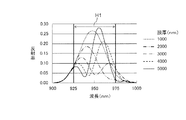
次に、測定対象物W上の膜厚の変化による反射率への影響について図3乃至図5を参照して説明する。図3には狭帯域光の反射スペクトルの例が示されており、図4には広帯域光の反射スペクトルの例が示されている。また、図5には、モデルとして用いる、中心波長950nmの狭帯域光及び広帯域光の発光スペクトルが示されている。 Next, the influence on the reflectance due to the change in the film thickness on the measurement target W will be described with reference to FIGS. FIG. 3 shows an example of a reflection spectrum of narrowband light, and FIG. 4 shows an example of a reflection spectrum of broadband light. FIG. 5 shows emission spectra of narrowband light and broadband light having a center wavelength of 950 nm used as a model.
図3及び図4は、950nmの中心波長に対して±25nmの範囲(波長幅H1=50nm)における、測定対象物W上の膜厚の変化による反射率への影響をモデル計算により評価したものである。とくに、基板としてシリコン、基板上に形成される薄膜として窒化ガリウム(GaN)を用いた場合について、GaNの膜厚(1000nm、2000nm、3000nm、4000nm及び5000nm)毎の反射スペクトルがどのように変化するかを評価したものである。 FIG. 3 and FIG. 4 show an evaluation of the influence on the reflectance due to the change of the film thickness on the measurement target W in the range of ± 25 nm (wavelength width H1 = 50 nm) with respect to the center wavelength of 950 nm by model calculation. It is. In particular, in the case where silicon is used as the substrate and gallium nitride (GaN) is used as the thin film formed on the substrate, how the reflection spectrum changes for each GaN film thickness (1000 nm, 2000 nm, 3000 nm, 4000 nm, and 5000 nm). It is evaluated.
なお、図5に示すように、狭帯域光は、発光スペクトルの半値幅(半値全幅)が37nmであり、半値幅が波長幅H1(=50nm)よりも小さい光である(図5中のB1参照)。広帯域光は、発光スペクトルの半値幅(半値全幅)が200nmであり、半値幅が50nmよりも大きい光である(図5中のB2参照)。 As shown in FIG. 5, the narrow-band light is light having a half-value width (full width at half maximum) of 37 nm and a half-value width smaller than the wavelength width H1 (= 50 nm) (B1 in FIG. 5). reference). The broadband light is light having a full width at half maximum (full width at half maximum) of 200 nm and a width at half maximum greater than 50 nm (see B2 in FIG. 5).
図3に示すように、狭帯域光の反射スペクトルは、膜厚の増大、すなわち1000nm、2000nm、3000nm、4000nm及び5000nmと増大すると共に形状(反射率の増減度合い)が変わっている。同様に、広帯域光の各反射スペクトルも、図4に示すように、膜厚の増大、すなわち1000nm、2000nm、3000nm、4000nm及び5000nmと増加すると共に形状(反射率の増減度合い)が変わっている。これらの図3及び図4を比較すると、広帯域光の反射スペクトルは、狭帯域光の反射スペクトルに比べて測定波長範囲にわたって大きく変化することがわかる。 As shown in FIG. 3, the reflection spectrum of narrowband light increases with increasing film thickness, that is, 1000 nm, 2000 nm, 3000 nm, 4000 nm, and 5000 nm, and the shape (degree of increase or decrease in reflectivity) changes. Similarly, as shown in FIG. 4, each reflection spectrum of broadband light also increases in film thickness, that is, 1000 nm, 2000 nm, 3000 nm, 4000 nm, and 5000 nm, and the shape (degree of increase / decrease in reflectance) changes. Comparing these FIG. 3 and FIG. 4, it can be seen that the reflection spectrum of the broadband light varies greatly over the measurement wavelength range as compared with the reflection spectrum of the narrow band light.
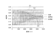
次いで、理想光、狭帯域光及び広帯域光、すなわち各発光スペクトルの半値幅の違いによる反射率への影響について図6を参照して説明する。図6には、理想光、狭帯域光及び広帯域光毎の反射率の膜厚依存性、すなわち反射率及び膜厚の関係の一例が示されている。ここで理想光とは発光スペクトルの半値幅が無視できるほど小さい光のことである。 Next, the influence on the reflectance due to the difference in half-value width of each emission spectrum will be described with reference to FIG. FIG. 6 shows an example of the film thickness dependence of the reflectivity for each of ideal light, narrowband light, and broadband light, that is, an example of the relationship between reflectivity and film thickness. Here, the ideal light is light that is so small that the half width of the emission spectrum can be ignored.
図6は、前述と同じように950nmの中心波長に対して±25nmの範囲(波長幅H1=50nm)における、中心波長950nmの理想光、狭帯域光及び広帯域光(各発光スペクトルの半値幅の違い)による反射率への影響をモデル計算により評価したものである。とくに、基板としてシリコン、基板上に形成される薄膜として窒化ガリウム(GaN)を用いた場合について、GaNの膜厚が増大するにつれて、反射率がどのように変化するかを評価したものである。なお、モデルとして用いる狭帯域光及び広帯域光毎の発光スペクトルは前述と同様に図5に示されている。温度の較正は、薄膜の成膜前の基板を用いて1000℃で行う。 FIG. 6 shows the ideal light, narrowband light, and broadband light (with half-width of each emission spectrum) in the range of ± 25 nm (wavelength width H1 = 50 nm) with respect to the center wavelength of 950 nm as described above. This is an evaluation of the influence on the reflectance due to (difference) by model calculation. In particular, in the case where silicon is used as the substrate and gallium nitride (GaN) is used as the thin film formed on the substrate, it is evaluated how the reflectance changes as the GaN film thickness increases. In addition, the emission spectrum for each narrowband light and broadband light used as a model is shown in FIG. Temperature calibration is performed at 1000 ° C. using a substrate before the thin film is formed.
図6に示すように、理想的な950nmでの反射率は膜厚の増大とともに正弦波状の振動を繰り返すことがわかる(図6中のC1参照)。この挙動は発光スペクトルの半値幅が0である場合に相当し、反射率の振動の振幅は一定で変化しない。一方、狭帯域光の発光スペクトルの半値幅が37nmである光源を用いて反射率を測定した場合には(図6中のC2参照)、反射率の振動の振幅が膜厚の増大とともに次第に減少することがわかる。膜をおおよそ5μm(5000nm)成長させた場合、測定した反射率は約17%で振幅はほぼ0になる。さらに、広帯域光の発光スペクトルの半値幅が200nmである光源を用いた場合には(図6中のC3参照)、反射率の振動の振幅の減衰はさらに急で、膜を4μm(4000nm)成長させた段階で反射率の振動の振幅はほぼ0になる。このように、反射率を測定するための広帯域光源2の発光スペクトルの半値幅が大きくなるにつれて、測定された反射率の振動の振幅は小さくなる。
As shown in FIG. 6, it can be seen that the ideal reflectance at 950 nm repeats sinusoidal vibration as the film thickness increases (see C1 in FIG. 6). This behavior corresponds to a case where the half-value width of the emission spectrum is 0, and the amplitude of the oscillation of the reflectance is constant and does not change. On the other hand, when the reflectance is measured using a light source having a half-width of the emission spectrum of narrowband light of 37 nm (see C2 in FIG. 6), the amplitude of reflectance vibration gradually decreases as the film thickness increases. I understand that When the film is grown approximately 5 μm (5000 nm), the measured reflectance is about 17% and the amplitude is almost zero. Furthermore, when a light source having a half-width of the emission spectrum of broadband light of 200 nm is used (see C3 in FIG. 6), the attenuation of the amplitude of the reflectance vibration is further steep, and the film grows by 4 μm (4000 nm). At this stage, the amplitude of the vibration of the reflectance becomes almost zero. Thus, as the half-value width of the emission spectrum of the
次に、測定対象物Wの温度を算出する場合の放射率補正について図7を参照して説明する。図7には、放射率(輻射率)の補正無し、放射率の補正有りで狭帯域光及び広帯域光毎の測定温度の膜厚依存性、すなわち測定温度及び膜厚の関係が示されている。 Next, emissivity correction when calculating the temperature of the measurement object W will be described with reference to FIG. FIG. 7 shows the film thickness dependence of the measurement temperature for each of the narrowband light and the broadband light without correction of the emissivity (emissivity) and with correction of the emissivity, that is, the relationship between the measurement temperature and the film thickness. .
図7の例は、モデル計算による熱輻射強度を図6に示された反射率を用いて放射率の補正を行い、測定対象物Wの温度を求めたものである。モデル計算の手順は、測定対象物Wの温度を1000℃とし、放射率(ε)を式(1)であるε=1−Rにより計算する。なお、熱輻射強度を950nm±25nmの波長範囲での積分値として求める。 In the example of FIG. 7, the temperature of the measurement object W is obtained by correcting the emissivity of the thermal radiation intensity by the model calculation using the reflectance shown in FIG. 6. In the model calculation procedure, the temperature of the measuring object W is set to 1000 ° C., and the emissivity (ε) is calculated from ε = 1−R in the equation (1). The heat radiation intensity is obtained as an integral value in the wavelength range of 950 nm ± 25 nm.
図7に示すように、放射率の補正を行わない場合には(図7中のD1参照)、測定温度は約978℃を中心として振動し、測定温度の振動の振幅は最大で±17℃程度である。一方、狭帯域光の発光スペクトルの半値幅が37nmである光源を用いて反射率を測定し、放射率補正を行った場合には(図7中のD2参照)、測定温度は中心の値が1000℃で振動の振幅は±5℃程度まで低減される。さらに、広帯域光の発光スペクトルの半値幅が200nmである光源を用いて測定した反射率をもとに放射率補正をした場合には(図7中のD3参照)、測定温度は1000℃を中心として±2℃の範囲に収まる。このように反射率を測定するための広帯域光源2の発光スペクトルの半値幅を少なくとも測定波長範囲の幅H1以上にすることで、熱輻射強度を測定する波長範囲を狭めることなく、温度測定精度を向上させることができる。
As shown in FIG. 7, when emissivity correction is not performed (see D1 in FIG. 7), the measurement temperature oscillates about 978 ° C., and the amplitude of the measurement temperature oscillation is ± 17 ° C. at the maximum. Degree. On the other hand, when the reflectance is measured using a light source having a half-width of the emission spectrum of narrowband light of 37 nm and the emissivity correction is performed (see D2 in FIG. 7), the measured temperature has a central value. At 1000 ° C., the amplitude of vibration is reduced to about ± 5 ° C. Furthermore, when the emissivity correction is performed based on the reflectance measured using a light source whose half-value width of the emission spectrum of broadband light is 200 nm (see D3 in FIG. 7), the measurement temperature is centered at 1000 ° C. As within ± 2 ° C. Thus, by setting the half-value width of the emission spectrum of the
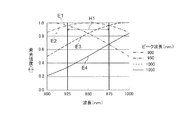
次いで、広帯域光の発光スペクトルのピーク波長の違いによる温度誤差について図8乃至図10を参照して説明する。図8には、半値幅が200nmでピーク波長が900nm、950nm、1000nm及び1050nmである光源の発光スペクトルが示されている。なお、測定波長範囲が950nmを中心として±25nm(波長範囲の幅H1=50nm)である。また、図9には、温度の振れ幅のピーク波長依存性、すなわち温度誤差及びピーク波長の関係が示されている。 Next, the temperature error due to the difference in the peak wavelength of the emission spectrum of the broadband light will be described with reference to FIGS. FIG. 8 shows an emission spectrum of a light source having a half width of 200 nm and peak wavelengths of 900 nm, 950 nm, 1000 nm, and 1050 nm. The measurement wavelength range is ± 25 nm (wavelength range width H1 = 50 nm) centered on 950 nm. FIG. 9 also shows the peak wavelength dependence of the temperature fluctuation width, that is, the relationship between the temperature error and the peak wavelength.
図8に示すように、広帯域光のピーク波長が900nmである場合には(図8中のE1参照)、光強度(すなわち熱輻射強度)が測定波長範囲にわたって光の波長増加に応じて減少しており、950nmである場合には(図8中のE2参照)、光強度が測定波長範囲において光の波長増加に応じて増加してから減少している。一方、広帯域光のピーク波長が1000nm又は1050nmである場合には(図8中のE3及びE4参照)、光強度が測定波長範囲にわたって光の波長増加に応じて増加している。 As shown in FIG. 8, when the peak wavelength of the broadband light is 900 nm (see E1 in FIG. 8), the light intensity (that is, the heat radiation intensity) decreases with increasing light wavelength over the measurement wavelength range. In the case of 950 nm (see E2 in FIG. 8), the light intensity increases and decreases as the wavelength of light increases in the measurement wavelength range. On the other hand, when the peak wavelength of the broadband light is 1000 nm or 1050 nm (see E3 and E4 in FIG. 8), the light intensity increases with increasing light wavelength over the measurement wavelength range.
図9に示すように、広帯域光のピーク波長が900nmである場合には、温度誤差が6℃と大きく、950nmである場合には、3.6℃程度となる。一方、広帯域光のピーク波長が1000nmである場合には、温度誤差が1.2℃程度と小さく、1050nmである場合には、2℃程度となる。このため、広帯域光のピーク波長が1000nm又は1050nmである光源、すなわち、広帯域光源2として、ピーク波長が熱輻射強度を測定する測定波長範囲より大きく、測定波長範囲にわたって光強度が波長増加に応じて増える光を発生させる光源を用いて測定を行った場合、放射率を補正して求めた測定対象物Wの温度誤差を非常に小さくすることができる。
As shown in FIG. 9, when the peak wavelength of the broadband light is 900 nm, the temperature error is as large as 6 ° C., and when it is 950 nm, it is about 3.6 ° C. On the other hand, when the peak wavelength of the broadband light is 1000 nm, the temperature error is as small as about 1.2 ° C., and when it is 1050 nm, it is about 2 ° C. For this reason, as a light source having a peak wavelength of broadband light of 1000 nm or 1050 nm, that is, the
図10は、広帯域光のピーク波長が1000nmである光源を用い、測定対象の温度が600℃の場合の本実施形態での測定温度のGaNの膜厚依存性を示したものである。なお、比較のために、従来の狭帯域光源(半値幅:37nm、ピーク波長:950nm)を反射率測定用光源として用いた場合を合わせて示す。温度の較正は成膜前の基板を用いて1000℃で行う。測定温度は約600.6℃を中心として振動し、測定温度の振れ幅は2.5μm程度で最大で±0.8℃程度(温度の振れ幅としては1.6℃程度)となり、膜厚の増大とともに振れ幅は小さくなる。一方、従来の狭帯域光源を用いた場合には、温度の振れ幅が最大5℃程度である。4μmから5μmにかけて狭帯域光源を用いたものとの振れ幅の差が最大となる。 FIG. 10 shows the dependence of the measurement temperature on the GaN film thickness in this embodiment when the light source having a peak wavelength of broadband light of 1000 nm is used and the temperature of the measurement target is 600 ° C. For comparison, a case where a conventional narrow-band light source (half width: 37 nm, peak wavelength: 950 nm) is used as a reflectance measurement light source is also shown. Temperature calibration is performed at 1000 ° C. using a substrate before film formation. The measurement temperature oscillates around 600.6 ° C, the measurement temperature fluctuation is about 2.5μm, and the maximum is about ± 0.8 ° C (temperature fluctuation is about 1.6 ° C). As the value increases, the swing width decreases. On the other hand, when a conventional narrow-band light source is used, the maximum temperature fluctuation is about 5 ° C. The difference in deflection width from that using a narrow-band light source is maximized from 4 μm to 5 μm.
したがって、測定波長範囲にわたって光強度が波長増加に応じて増える光を発生させる光源を用いることで、熱輻射強度を測定する波長範囲を狭めることなく、温度測定精度を向上させることができる。さらに、較正温度から大きく離れた600℃程度の低温での温度測定でも誤差が小さいことがわかる。また、膜厚が1μm以上で狭帯域光源を用いたものとの有意差が得られていることがわかる。 Therefore, by using a light source that generates light whose light intensity increases as the wavelength increases over the measurement wavelength range, the temperature measurement accuracy can be improved without narrowing the wavelength range for measuring the heat radiation intensity. Further, it can be seen that the error is small even in the temperature measurement at a low temperature of about 600 ° C. which is far from the calibration temperature. Further, it can be seen that a significant difference is obtained from that using a narrow-band light source with a film thickness of 1 μm or more.
図11は、上記と同様の光源を用い、温度の振れ幅の温度依存性を示したものである。上述のように基板上に成膜する薄膜の膜厚が増大するにつれて測定温度は振動するが、図11に示すように、振動する測定温度の中心値は狭帯域光源を用いた従来技術と広帯域光源を用いた本実施形態ではほとんど差がない。この中心の温度から測定対象の温度を引いたものを中心温度偏差とする。中心温度の偏差は測定対象の温度が600℃から1200℃の範囲で、緩やかに減少し、1℃以内となる。一方、温度の振れ幅は狭帯域光源を用いた従来技術では測定対象の温度が高くなるにつれて増大し、測定対象の温度が600℃から1200℃の範囲で、5℃弱から12℃まで増大する。他方、広帯域光源を用いた本実施形態の場合、振れ幅は上記の測定温度範囲で2℃より小さい。 FIG. 11 shows the temperature dependence of the temperature fluctuation using the same light source as described above. As described above, the measurement temperature oscillates as the thickness of the thin film formed on the substrate increases. As shown in FIG. 11, the center value of the oscillating measurement temperature is the same as that of the conventional technique using a narrow band light source and the broadband. In this embodiment using a light source, there is almost no difference. A value obtained by subtracting the temperature of the measurement object from the center temperature is defined as a center temperature deviation. The deviation of the center temperature decreases gradually within 1 ° C. when the temperature to be measured is in the range of 600 ° C. to 1200 ° C. On the other hand, in the conventional technique using a narrow band light source, the temperature fluctuation width increases as the temperature of the measurement target increases, and the temperature of the measurement target increases from a little less than 5 ° C. to 12 ° C. in the range of 600 ° C. to 1200 ° C. . On the other hand, in the case of the present embodiment using a broadband light source, the fluctuation width is smaller than 2 ° C. in the above measurement temperature range.
上述のように、基板上に成膜する膜の膜厚が1μm以上の厚い場合であっても高い精度で測定することができる。また、温度範囲が例えば600℃から1200℃と大きく変化する場合でも同様である。したがって、とくに幅広い膜厚範囲で大きな温度差を持つ成膜プロセスで、非常に有効となる。 As described above, even when the film formed on the substrate is thicker than 1 μm, it can be measured with high accuracy. The same applies to the case where the temperature range changes greatly from 600 ° C. to 1200 ° C., for example. Therefore, it is very effective especially in a film forming process having a large temperature difference in a wide film thickness range.
ここで、通常、反射率を測定するための外部の光源としては、発光スペクトルの半値幅が小さい発光ダイオード(LED:Light Emitting Diode)を用いることが多い。これは、LEDが取り扱いに便利及び安価で、反射率を測定するためには十分な発光強度を持つ上、発光スペクトルの半値幅が小さいLEDを使うことによって、LEDの発光スペクトルのピーク波長で、反射率を測定することができるためである。 Here, usually, as an external light source for measuring the reflectance, a light emitting diode (LED: Light Emitting Diode) having a small half-value width of an emission spectrum is often used. This is because the LED is convenient and inexpensive to handle, has sufficient emission intensity to measure reflectance, and uses an LED with a small half-value width of the emission spectrum, so that at the peak wavelength of the emission spectrum of the LED, This is because the reflectance can be measured.
一方、本実施形態では、前述とは逆に、反射率を測定するための光源として、発光スペクトルの半値幅が広い広帯域光源2を用いる。具体的には、熱輻射強度を測定する測定波長範囲の幅に比べて、光源の発光スペクトルの半値幅が同じかより大きい広帯域光源2を用いる。広帯域光源2の発光スペクトルがいくつかのピークを持つ場合には、熱輻射強度を測定する測定波長範囲内に最も大きなピークに対する半値幅が測定波長範囲の幅以上であることが好ましい。
On the other hand, in the present embodiment, contrary to the above, the
なお、発光スペクトルの半値幅が広がることにより、反射スペクトルの測定値は、測定対象物W上に形成された薄膜の干渉の効果をより強く受けることになるが、膜厚の変化に応じて振動する反射率の振幅は膜厚の増加に伴って小さくなる。この振幅が小さくなる反射率を用いて熱輻射強度の放射率の補正を行うことで、温度測定精度を向上させることができる。 Note that, since the half-value width of the emission spectrum is widened, the measurement value of the reflection spectrum is more strongly affected by the interference of the thin film formed on the measurement target W, but it vibrates according to the change in the film thickness. The amplitude of the reflectivity decreases with increasing film thickness. The temperature measurement accuracy can be improved by correcting the emissivity of the thermal radiation intensity using the reflectance with which the amplitude becomes small.
熱輻射強度を測定する測定波長範囲については、測定対象の測定すべき温度によって適切に決めることが可能である。MOCVDあるいはMBEによる化合物半導体の製造においては、おおむね500℃以上1200℃以下の温度範囲に基板を加熱する場合がほとんどである。この場合、熱輻射強度を測定する波長としては、400nm以上3000nm以下の波長を設定すると、温度の測定精度が高くなるため好適である。より好ましくは600nm以上2000nm以下の間、さらに好ましくは800nm以上1500nm以下の間に設定する。また、前述の温度範囲より高温での測定が必要である場合には上記の波長範囲をより短く設定すると良く、逆により低温での測定が必要な場合にはより長く設定すると良い。 The measurement wavelength range in which the heat radiation intensity is measured can be appropriately determined depending on the temperature to be measured of the measurement target. In the production of a compound semiconductor by MOCVD or MBE, the substrate is mostly heated to a temperature range of about 500 ° C. to 1200 ° C. in most cases. In this case, it is preferable to set a wavelength of 400 nm or more and 3000 nm or less as the wavelength for measuring the heat radiation intensity because the temperature measurement accuracy is increased. More preferably, it is set between 600 nm and 2000 nm, and more preferably between 800 nm and 1500 nm. In addition, the wavelength range may be set shorter when measurement at a higher temperature than the above temperature range is required, and may be set longer when measurement at a lower temperature is required.
また、熱輻射強度を測定する波長範囲の幅H1については、必要とする温度の精度や下限、測定時間の上限などにより決定される。前述の化合物半導体の製造装置の場合には、±2℃の温度の精度、測定下限の温度が500℃、測定時間が1ミリ秒の場合、熱輻射強度を測定する波長範囲の幅は少なくとも20nm以上であると、測定精度が高くなるため好適である。より好ましくは30nm以上、さらに好ましくは40nm以上、最も好ましくは50nm以上である。 Further, the width H1 of the wavelength range for measuring the heat radiation intensity is determined by the accuracy and lower limit of the required temperature, the upper limit of the measurement time, and the like. In the case of the above-described compound semiconductor manufacturing apparatus, when the temperature accuracy is ± 2 ° C., the measurement lower limit temperature is 500 ° C., and the measurement time is 1 millisecond, the width of the wavelength range for measuring the heat radiation intensity is at least 20 nm. The above is preferable because the measurement accuracy increases. More preferably, it is 30 nm or more, More preferably, it is 40 nm or more, Most preferably, it is 50 nm or more.
また、反射率を測定するための広帯域光源2については、すでに述べたように、上述の熱輻射強度を測定する測定波長範囲に対する光源の発光スペクトルの半値幅や発光ピーク位置が重要である。具体的には、広帯域光源2の発光スペクトルの半値幅は、熱輻射強度を測定するための測定波長範囲の幅H1に比べて1倍以上であることが必要である(より好ましくは1.5倍以上、さらに好ましくは2倍以上である)。また、ピーク波長が測定波長範囲より大きく、測定波長範囲にわたって光強度が波長増加に応じて増える光を発生させることが必要である。測定波長範囲を決める光学フィルタ4の光透過スペクトルが急峻でなく測定波長範囲を精度良く決められない場合には、透過スペクトルの半値幅を測定波長範囲と定義することも可能である。
As for the
本実施形態で用いることができる光源としては、ハロゲンランプ、LED、スーパーコンティニューム光源など公知のものを単独でまたは組み合わせて用いることができる。また、光源の発光スペクトルを好適なものにするために、適切な光学フィルタと組み合わせて用いることができる。また、LEDの場合には、複数の発光波長の異なるLEDランプ、あるいはLEDチップを組み合わせて用いることができる。また、1つのLEDチップ内に、異なる発光波長の活性層を積層したものを用いることができる。 As a light source that can be used in the present embodiment, a known light source such as a halogen lamp, an LED, or a supercontinuum light source can be used alone or in combination. Further, in order to make the emission spectrum of the light source suitable, it can be used in combination with an appropriate optical filter. In the case of an LED, a plurality of LED lamps or LED chips having different emission wavelengths can be used in combination. Moreover, what laminated | stacked the active layer of a different light emission wavelength in one LED chip can be used.
なお、広帯域光源2の発光スペクトルが主要なピークの裾の波長領域に小さなサイドピークを有していても、広帯域光源2の発光スペクトルのピーク波長としては、測定波長範囲内で観測される発光スペクトルの全体的特徴を左右するピークについての波長とする。また、前述の説明においては、広帯域光源2の発光スペクトルは、熱輻射強度を測定するための測定波長範囲内で滑らかで連続的であることを前提としているが、これに限るものではなく、おおむね等間隔の比較的小さな波長間隔で離散している線スペクトルで構成されていても良い。
Even if the emission spectrum of the
ただし、この波長範囲に含まれる線スペクトルの数が少ない場合には、本実施形態に係る効果が顕著とならない。このため、熱輻射強度を測定する波長範囲の中に含まれる線スペクトルの数は5以上であることが望ましく、より好ましくは7以上であり、さらに好ましくは10以上である。これらの線スペクトルのピーク波長での発光強度を次々と結ぶことで、疑似的な連続スペクトルを求めることも可能である。広帯域光源2の発光スペクトルの半値幅はこの擬似的な連続スペクトルで定義することができる。この場合、広帯域光源2の発光スペクトルのピーク波長については、前述の疑似的な連続スペクトルの強度が、熱輻射強度を測定するための測定波長範囲内で、おおむね長波長側で増大している場合と定義する。
However, when the number of line spectra included in this wavelength range is small, the effect according to the present embodiment is not significant. For this reason, the number of line spectra included in the wavelength range for measuring the heat radiation intensity is desirably 5 or more, more preferably 7 or more, and further preferably 10 or more. It is also possible to obtain a pseudo continuous spectrum by connecting the emission intensities at the peak wavelengths of these line spectra one after another. The half width of the emission spectrum of the
以上説明したように、実施形態によれば、広帯域光源2の広帯域光の発光スペクトルは、半値幅が測定波長範囲の幅H1以上であり、測定波長範囲において波長増加に応じて光強度が増大するスペクトルであることから、受光部5により受光された上記の広帯域光源2からの光は、光強度が長波長になるに従って増大する光となり、受光された光の熱輻射スペクトルが黒体の熱輻射スペクトルに近づく。このことが、熱輻射強度を測定する波長範囲を変えず、熱輻射強度の精度及び信号強度の低下を抑え、温度測定精度を向上させることができる原因であると考えられる。
As described above, according to the embodiment, the emission spectrum of the broadband light of the
この原理に基づく、熱輻射強度の測定波長範囲での、発光波長依存性は以下のようになる。すなわち、測定温度範囲がおおむね800℃から1100℃の範囲の場合、測定波長範囲の上限での熱輻射強度(Ph)を測定波長範囲の下限での熱輻射強度(Pl)で割ったものは以下の関係である。 Based on this principle, the emission wavelength dependency in the measurement wavelength range of the thermal radiation intensity is as follows. That is, when the measurement temperature range is approximately 800 ° C. to 1100 ° C., the heat radiation intensity (Ph) at the upper limit of the measurement wavelength range divided by the heat radiation intensity (Pl) at the lower limit of the measurement wavelength range is as follows: It is a relationship.
Ph/Pl=9.8×exp(Δλ×ξ)
ここで、expは自然対数の底に対する指数関数、Δλは熱輻射強度の測定波長範囲(単位はμm)、ξは熱輻射強度の測定波長範囲の中心波長(以下λ0と記す、単位はμm)についての関数で、
ξ=−29.8×λ0+36.8
で表される。
Ph / Pl = 9.8 × exp (Δλ × ξ)
Here, exp is an exponential function with respect to the base of natural logarithm, Δλ is a measurement wavelength range of thermal radiation intensity (unit: μm), ξ is a center wavelength of a measurement wavelength range of thermal radiation intensity (hereinafter referred to as λ0, unit is μm) Is a function about
ξ = −29.8 × λ0 + 36.8
It is represented by
図12に、いくつかの具体的なλ0とΔλについてのPh/Plの好ましい範囲を示す。たとえば、熱輻射強度を測定する波長範囲の中心波長(λ0)が0.9μm、測定範囲の波長の幅(Δλ)が0.1μmの場合(測定波長範囲は0.85〜0.95μm)、本実施形態の広帯域光源における0.95μm(上限波長)の光強度は0.85μm(下限波長)の光強度の1.3倍から20倍の範囲にあることが好ましい。 FIG. 12 shows the preferred range of Ph / Pl for some specific λ0 and Δλ. For example, when the center wavelength (λ0) of the wavelength range for measuring the heat radiation intensity is 0.9 μm and the wavelength width (Δλ) of the measurement range is 0.1 μm (measurement wavelength range is 0.85 to 0.95 μm), The light intensity of 0.95 μm (upper limit wavelength) in the broadband light source of the present embodiment is preferably in the range of 1.3 to 20 times the light intensity of 0.85 μm (lower limit wavelength).
なお、これまでの説明では、測定対象としてシリコン基板上にGaNを成膜する場合について述べてきたが、サファイアのような透明基板にも用いることができる。ただし、その場合には、成膜される薄膜が光透過性である場合、測定対象は、基板を保持する光を透過させない治具(サセプタ)である。また、基板上に成膜する薄膜の材料はGaNに限定されるものではなく、一般的な薄膜材料について用いることができる。薄膜材料の具体例としては、窒化アルミニウム(AlN)、砒化ガリウム(GaAs)、セレン化亜鉛(ZnSe)などに代表される化合物半導体およびその混晶、シリコン、ゲルマニウムに代表される4族半導体、およびその混晶、窒化ケイ素、酸化ケイ素のようなアモルファス材料などが挙げられる。またそれらの積層構造についても同様である。 In the description so far, the case where GaN is formed on a silicon substrate as a measurement target has been described, but it can also be used for a transparent substrate such as sapphire. However, in that case, when the thin film to be formed is light-transmitting, the measurement object is a jig (susceptor) that does not transmit light that holds the substrate. Further, the material of the thin film formed on the substrate is not limited to GaN, and a general thin film material can be used. Specific examples of the thin film material include compound semiconductors typified by aluminum nitride (AlN), gallium arsenide (GaAs), zinc selenide (ZnSe), and mixed crystals thereof, group 4 semiconductors typified by silicon and germanium, and Examples thereof include amorphous materials such as mixed crystals, silicon nitride, and silicon oxide. The same applies to those laminated structures.
また、前述の実施形態においては、MOCVDやMBEなどでの成膜を主な適用例として挙げているが、成膜に伴う基板の温度変化が生ずる可能性があれば、MOCVDやMBEに限るものではなく、スパッタや蒸着などの手法にも適用可能であり、さらには成膜に限らない一般的な温度測定に対しても適用することが可能である。また、前述の放射温度計1の構成については、図1に示すものが一つの例であるが、この構成要素や構成方法等にさまざまな変更を加えることが可能である。
In the above-described embodiment, film formation by MOCVD, MBE, or the like is given as a main application example. However, if there is a possibility that the temperature of the substrate changes due to film formation, the film formation is limited to MOCVD or MBE. Instead, it can be applied to techniques such as sputtering and vapor deposition, and can also be applied to general temperature measurement not limited to film formation. Further, the configuration of the
以上、本発明のいくつかの実施形態を説明したが、これらの実施形態は、例として提示したものであり、発明の範囲を限定することは意図していない。これら新規な実施形態は、その他の様々な形態で実施されることが可能であり、発明の要旨を逸脱しない範囲で、種々の省略、置き換え、変更を行うことができる。これら実施形態やその変形は、発明の範囲や要旨に含まれるとともに、特許請求の範囲に記載された発明とその均等の範囲に含まれる。 As mentioned above, although some embodiment of this invention was described, these embodiment is shown as an example and is not intending limiting the range of invention. These novel embodiments can be implemented in various other forms, and various omissions, replacements, and changes can be made without departing from the scope of the invention. These embodiments and modifications thereof are included in the scope and gist of the invention, and are included in the invention described in the claims and the equivalents thereof.
1 放射温度計
2 広帯域光源
3 ハーフミラー
4 光学フィルタ
5 受光部
6 算出部
H1 測定波長範囲の幅
L1 広帯域光
W 測定対象物
DESCRIPTION OF
Claims (7)
前記広帯域光源により発生した前記広帯域の光が前記測定対象物に入射し、その測定対象物によって反射された反射光及び前記測定対象物から放射された熱輻射光のうち所定の波長範囲の光だけを通す光学フィルタと、
前記光学フィルタを通過した前記所定の波長範囲の反射光及び熱輻射光を受光する受光部と、
前記受光部により受光された前記所定の波長範囲の反射光強度に基づいて前記所定の波長範囲の熱輻射光強度を補正し、前記測定対象物の温度を算出する算出部と、
を備え、
前記広帯域の光の発光スペクトルは、半値全幅が前記所定の波長範囲の幅以上であり、前記所定の波長範囲において長波長になるにしたがい光強度が増大するスペクトルであり、
前記広帯域光源は前記測定対象物の加熱源とは別個に設けられている、ことを特徴とする放射温度計。 A broadband light source that generates broadband light to irradiate the measurement object;
The broadband light generated by the broadband light source is incident on the measurement object, and only reflected light reflected by the measurement object and heat radiation light emitted from the measurement object within a predetermined wavelength range. An optical filter that passes through,
A light receiving unit that receives reflected light and heat radiation in the predetermined wavelength range that has passed through the optical filter;
A calculation unit that corrects the heat radiation light intensity of the predetermined wavelength range based on the reflected light intensity of the predetermined wavelength range received by the light receiving unit, and calculates the temperature of the measurement object;
With
Emission spectrum of the broadband light is the full width at half maximum equal to or greater than the width of said predetermined wavelength range, Ri spectrum der light intensity increases in accordance becomes longer wavelengths in the predetermined wavelength range,
The radiation thermometer, wherein the broadband light source is provided separately from a heating source of the measurement object .
前記広帯域光源により発生した前記広帯域の光を測定対象物に照射する工程と、
前記測定対象物によって反射された反射光及び前記測定対象物から放射された熱輻射光のうち所定の波長範囲の光だけを光学フィルタにより通す工程と、
前記光学フィルタを通過した前記所定の波長範囲の反射光及び熱輻射光を受光部により受光する工程と、
前記受光部により受光された前記所定の波長範囲の反射光強度に基づいて前記所定の波長範囲の熱輻射光強度を補正し、前記測定対象物の温度を算出部により算出する工程と、
を有し、
前記広帯域の光の発光スペクトルは、半値全幅が前記所定の波長範囲の幅以上であり、前記所定の波長範囲において長波長になるにしたがい光強度が増大するスペクトルであり、
前記広帯域光源は前記測定対象物の加熱源とは別個に設けられている、ことを特徴とする温度測定方法。 Generating broadband light with a broadband light source;
Irradiating a measurement object with the broadband light generated by the broadband light source;
A step of passing only light in a predetermined wavelength range among reflected light reflected by the measurement object and heat radiation light emitted from the measurement object by an optical filter;
Receiving a reflected light and heat radiation light in the predetermined wavelength range that has passed through the optical filter by a light receiving unit;
Correcting the heat radiation intensity of the predetermined wavelength range based on the reflected light intensity of the predetermined wavelength range received by the light receiving unit, and calculating the temperature of the measurement object by the calculation unit;
Have
Emission spectrum of the broadband light is the full width at half maximum equal to or greater than the width of said predetermined wavelength range, Ri spectrum der light intensity increases in accordance becomes longer wavelengths in the predetermined wavelength range,
The temperature measuring method, wherein the broadband light source is provided separately from a heating source of the measurement object .
Priority Applications (2)
| Application Number | Priority Date | Filing Date | Title |
|---|---|---|---|
| JP2014213906A JP6479407B2 (en) | 2014-10-20 | 2014-10-20 | Radiation thermometer and temperature measurement method |
| US14/880,561 US9995632B2 (en) | 2014-10-20 | 2015-10-12 | Radiation thermometer and thermometry method |
Applications Claiming Priority (1)
| Application Number | Priority Date | Filing Date | Title |
|---|---|---|---|
| JP2014213906A JP6479407B2 (en) | 2014-10-20 | 2014-10-20 | Radiation thermometer and temperature measurement method |
Publications (2)
| Publication Number | Publication Date |
|---|---|
| JP2016080590A JP2016080590A (en) | 2016-05-16 |
| JP6479407B2 true JP6479407B2 (en) | 2019-03-06 |
Family
ID=55748797
Family Applications (1)
| Application Number | Title | Priority Date | Filing Date |
|---|---|---|---|
| JP2014213906A Active JP6479407B2 (en) | 2014-10-20 | 2014-10-20 | Radiation thermometer and temperature measurement method |
Country Status (2)
| Country | Link |
|---|---|
| US (1) | US9995632B2 (en) |
| JP (1) | JP6479407B2 (en) |
Families Citing this family (2)
| Publication number | Priority date | Publication date | Assignee | Title |
|---|---|---|---|---|
| JP6479525B2 (en) | 2015-03-27 | 2019-03-06 | 株式会社ニューフレアテクノロジー | Film forming apparatus and temperature measuring method |
| WO2017061333A1 (en) * | 2015-10-08 | 2017-04-13 | 株式会社ニューフレアテクノロジー | Vapor-phase growth rate measurement device, vapor-phase growth device, and growth rate detection method |
Family Cites Families (18)
| Publication number | Priority date | Publication date | Assignee | Title |
|---|---|---|---|---|
| US5166080A (en) * | 1991-04-29 | 1992-11-24 | Luxtron Corporation | Techniques for measuring the thickness of a film formed on a substrate |
| US5154512A (en) * | 1990-04-10 | 1992-10-13 | Luxtron Corporation | Non-contact techniques for measuring temperature or radiation-heated objects |
| JPH10111186A (en) * | 1996-10-03 | 1998-04-28 | Hitachi Ltd | Method and apparatus for measuring temperature of semiconductor substrate |
| US5841110A (en) | 1997-08-27 | 1998-11-24 | Steag-Ast Gmbh | Method and apparatus for improved temperature control in rapid thermal processing (RTP) systems |
| US6448097B1 (en) * | 2001-07-23 | 2002-09-10 | Advanced Micro Devices Inc. | Measure fluorescence from chemical released during trim etch |
| WO2004010094A1 (en) * | 2002-07-19 | 2004-01-29 | Luxtron Corporation | Emissivity corrected radiation pyrometer integral with a reflectometer and roughness sensor for remote measuring of true surface temperatures |
| US7069769B2 (en) * | 2004-01-20 | 2006-07-04 | Academia Sinica | Ultraviolet photoacoustic ozone detection |
| US7354772B2 (en) * | 2004-05-03 | 2008-04-08 | Naresh Menon | Tag free bio sensing micro strip |
| WO2007005489A2 (en) * | 2005-07-05 | 2007-01-11 | Mattson Technology, Inc. | Method and system for determining optical properties of semiconductor wafers |
| KR100698766B1 (en) * | 2005-09-07 | 2007-03-23 | 한국과학기술원 | Apparatus for Monitoring Failure Positions in Wavelength Division Multiplexing-Passive Optical Networks and Wavelength Division Multiplexing-Passive Optical Network Systems Having the Apparatus |
| US20070076780A1 (en) * | 2005-09-30 | 2007-04-05 | Champetier Robert J | Devices, systems and methods for determining temperature and/or optical characteristics of a substrate |
| DE102005059338A1 (en) * | 2005-12-08 | 2007-06-14 | Carl Zeiss Jena Gmbh | Method and arrangement for the examination of samples |
| GB2447925B (en) * | 2007-03-28 | 2010-04-07 | Internat Moisture Analysers Ltd | Fluid detector |
| CN101945689B (en) * | 2008-01-30 | 2012-07-18 | 应用材料公司 | System and method for pre-ionization of surface wave launched plasma discharge sources |
| JP5500120B2 (en) * | 2011-04-25 | 2014-05-21 | パナソニック株式会社 | Inspection method for electronic devices |
| US9182351B2 (en) * | 2013-11-26 | 2015-11-10 | Nanometrics Incorporated | Optical metrology system for spectral imaging of a sample |
| US9766463B2 (en) * | 2014-01-21 | 2017-09-19 | Osterhout Group, Inc. | See-through computer display systems |
| KR102243553B1 (en) * | 2014-07-16 | 2021-04-22 | 삼성전자주식회사 | Organic photoelectronic device and image sensor |
-
2014
- 2014-10-20 JP JP2014213906A patent/JP6479407B2/en active Active
-
2015
- 2015-10-12 US US14/880,561 patent/US9995632B2/en active Active
Also Published As
| Publication number | Publication date |
|---|---|
| JP2016080590A (en) | 2016-05-16 |
| US9995632B2 (en) | 2018-06-12 |
| US20160109299A1 (en) | 2016-04-21 |
Similar Documents
| Publication | Publication Date | Title |
|---|---|---|
| US8282272B2 (en) | Calibration substrate and method of calibration therefor | |
| US20150276388A1 (en) | Curvature measurement apparatus and method | |
| JP6479525B2 (en) | Film forming apparatus and temperature measuring method | |
| TWI661085B (en) | Apparatus and method for controlling temperature in a processing chamber of a CVD reactor by using two temperature sensing devices | |
| US10957564B2 (en) | Self-calibration apparatus and method for real-time temperature measurement system of MOCVD device | |
| US8786841B2 (en) | Thin film temperature measurement using optical absorption edge wavelength | |
| JP6479407B2 (en) | Radiation thermometer and temperature measurement method | |
| EP2741062B1 (en) | Method for measuring temperature of semiconductor layer | |
| TWI663385B (en) | Optical temperature sensor and manufacturing method of optical temperature sensor | |
| US6679946B1 (en) | Method and apparatus for controlling substrate temperature and layer thickness during film formation | |
| KR102527612B1 (en) | Systems and methods for heat treatment and temperature measurement of workpieces at low temperatures | |
| JP2020153982A (en) | Growth rate detection apparatus, vapor deposition apparatus and vapor deposition rate detection method | |
| US10281335B2 (en) | Pulsed radiation sources for transmission pyrometry | |
| JP6301214B2 (en) | Optical temperature sensor and method for controlling optical temperature sensor | |
| JP7037372B2 (en) | Film forming equipment and film forming method | |
| KR20150056269A (en) | Apparatus, method for processing substrate and apparatus, method for laser heat treatment using the same | |
| CN104697637B (en) | A kind of real time temperature measurement method of film growth | |
| CN117157845A (en) | Mode-hop-free laser module | |
| TWI646313B (en) | Temperature measuring device and temperature measuring method | |
| CN104726841A (en) | Assistant temperature correction device and method for semiconductor film growth reaction chamber | |
| US20240145274A1 (en) | Low temperature measurement of semiconductor substrates | |
| KR20240031371A (en) | How to Etch or Deposit Thin Films | |
| KR20240140129A (en) | Method for emissivity-corrected high-temperature measurements | |
| JP6546064B2 (en) | Temperature measuring device | |
| JPH11248539A (en) | Non-contact temperature measuring device |
Legal Events
| Date | Code | Title | Description |
|---|---|---|---|
| A621 | Written request for application examination |
Free format text: JAPANESE INTERMEDIATE CODE: A621 Effective date: 20170724 |
|
| A977 | Report on retrieval |
Free format text: JAPANESE INTERMEDIATE CODE: A971007 Effective date: 20180328 |
|
| A131 | Notification of reasons for refusal |
Free format text: JAPANESE INTERMEDIATE CODE: A131 Effective date: 20180420 |
|
| A521 | Request for written amendment filed |
Free format text: JAPANESE INTERMEDIATE CODE: A523 Effective date: 20180615 |
|
| A131 | Notification of reasons for refusal |
Free format text: JAPANESE INTERMEDIATE CODE: A131 Effective date: 20181026 |
|
| A521 | Request for written amendment filed |
Free format text: JAPANESE INTERMEDIATE CODE: A523 Effective date: 20181219 |
|
| TRDD | Decision of grant or rejection written | ||
| A01 | Written decision to grant a patent or to grant a registration (utility model) |
Free format text: JAPANESE INTERMEDIATE CODE: A01 Effective date: 20190108 |
|
| A61 | First payment of annual fees (during grant procedure) |
Free format text: JAPANESE INTERMEDIATE CODE: A61 Effective date: 20190206 |
|
| R150 | Certificate of patent or registration of utility model |
Ref document number: 6479407 Country of ref document: JP Free format text: JAPANESE INTERMEDIATE CODE: R150 |
|
| R250 | Receipt of annual fees |
Free format text: JAPANESE INTERMEDIATE CODE: R250 |
|
| R250 | Receipt of annual fees |
Free format text: JAPANESE INTERMEDIATE CODE: R250 |
|
| R250 | Receipt of annual fees |
Free format text: JAPANESE INTERMEDIATE CODE: R250 |