JP6478565B2 - Imprint system and article manufacturing method - Google Patents
Imprint system and article manufacturing method Download PDFInfo
- Publication number
- JP6478565B2 JP6478565B2 JP2014226406A JP2014226406A JP6478565B2 JP 6478565 B2 JP6478565 B2 JP 6478565B2 JP 2014226406 A JP2014226406 A JP 2014226406A JP 2014226406 A JP2014226406 A JP 2014226406A JP 6478565 B2 JP6478565 B2 JP 6478565B2
- Authority
- JP
- Japan
- Prior art keywords
- imprint
- substrate
- mold
- map
- pattern
- Prior art date
- Legal status (The legal status is an assumption and is not a legal conclusion. Google has not performed a legal analysis and makes no representation as to the accuracy of the status listed.)
- Active
Links
Images


Classifications
-
- B—PERFORMING OPERATIONS; TRANSPORTING
- B29—WORKING OF PLASTICS; WORKING OF SUBSTANCES IN A PLASTIC STATE IN GENERAL
- B29C—SHAPING OR JOINING OF PLASTICS; SHAPING OF MATERIAL IN A PLASTIC STATE, NOT OTHERWISE PROVIDED FOR; AFTER-TREATMENT OF THE SHAPED PRODUCTS, e.g. REPAIRING
- B29C43/00—Compression moulding, i.e. applying external pressure to flow the moulding material; Apparatus therefor
- B29C43/32—Component parts, details or accessories; Auxiliary operations
- B29C43/58—Measuring, controlling or regulating
-
- G—PHYSICS
- G03—PHOTOGRAPHY; CINEMATOGRAPHY; ANALOGOUS TECHNIQUES USING WAVES OTHER THAN OPTICAL WAVES; ELECTROGRAPHY; HOLOGRAPHY
- G03F—PHOTOMECHANICAL PRODUCTION OF TEXTURED OR PATTERNED SURFACES, e.g. FOR PRINTING, FOR PROCESSING OF SEMICONDUCTOR DEVICES; MATERIALS THEREFOR; ORIGINALS THEREFOR; APPARATUS SPECIALLY ADAPTED THEREFOR
- G03F7/00—Photomechanical, e.g. photolithographic, production of textured or patterned surfaces, e.g. printing surfaces; Materials therefor, e.g. comprising photoresists; Apparatus specially adapted therefor
- G03F7/0002—Lithographic processes using patterning methods other than those involving the exposure to radiation, e.g. by stamping
Description
本発明は、インプリントシステム及び物品の製造方法に関する。 The present invention relates to an imprint system and an article manufacturing method.
インプリント技術は、ナノスケールの微細パターンの転写を可能にする技術であり、半導体デバイスや磁気記憶媒体の量産用ナノリソグラフィ技術の1つとして注目されている。インプリント技術を用いたインプリント装置は、パターンが形成されたモールド(原版)と基板上の樹脂(インプリント材)とを接触させた状態で樹脂を硬化させ、硬化した樹脂からモールドを引き離すことで基板上にパターンを形成する。かかるインプリント装置では、樹脂硬化法として、一般に、紫外線などの光の照射によって基板上の樹脂を硬化させる光硬化法が採用されている。 The imprint technique is a technique that enables transfer of a nanoscale fine pattern, and has attracted attention as one of nanolithography techniques for mass production of semiconductor devices and magnetic storage media. The imprint apparatus using the imprint technique cures the resin in a state where the mold (original plate) on which the pattern is formed and the resin (imprint material) on the substrate are in contact with each other, and pulls the mold away from the cured resin. A pattern is formed on the substrate. Such an imprint apparatus generally employs a photocuring method in which a resin on a substrate is cured by irradiation with light such as ultraviolet rays.
また、インプリント装置では、基板上に樹脂を供給(塗布)する際に、例えば、インクジェット法を用いて基板上に樹脂の液滴の配列を形成している。そして、基板上の樹脂(液滴)にモールドを押し付けることで、かかる樹脂をモールドのパターン(凹部)に充填させている。但し、インプリント装置においては、モールドのパターンの違いや製造ばらつき、装置の動作ばらつきなどによって、基板上に形成されるパターンの欠陥や残膜厚(RLT)の異常などの問題が発生し、良質なパターンを形成することが困難である。 In the imprint apparatus, when resin is supplied (applied) onto a substrate, an array of resin droplets is formed on the substrate using, for example, an inkjet method. Then, by pressing the mold against the resin (droplets) on the substrate, the resin is filled in the mold pattern (concave portion). However, in the imprint apparatus, problems such as defects in the pattern formed on the substrate and abnormal residual film thickness (RLT) occur due to differences in mold patterns, manufacturing variations, apparatus operation variations, etc. It is difficult to form a simple pattern.
このような問題を回避するために、樹脂の液滴の基板上における供給位置を示すマップ(樹脂塗布パターン、インプリントレシピ、ドロップレシピ)を最適化する技術が提案されている(特許文献1及び2参照)。特許文献1には、モールドのパターンへの樹脂の充填量、基板上に形成すべき残膜厚、基板のショット領域やエッジの位置、下地(基板)における凹凸分布、及び、後工程での加工寸法のばらつきを考慮してインプリントレシピを作成する方法が開示されている。また、特許文献2には、半導体集積回路を構成する回路ブロックごとに欠陥数が最も少ないドロップレシピを選択及び収集するドロップレシピ作成支援データベースを作成する方法が開示されている。
In order to avoid such a problem, a technique for optimizing a map (resin application pattern, imprint recipe, drop recipe) indicating a supply position of a resin droplet on a substrate has been proposed (
インプリント装置では、インプリント処理を繰り返すことで、モールドのパターン、即ち、凹部に剥離しきれない樹脂が徐々に堆積(付着)し、モールドのパターンの形状(凹凸形状)が変化してしまう。そこで、一定回数のインプリント処理が終了したら、モールドを装置から外して洗浄し、洗浄されたモールドを装置に再び取り付けてインプリント処理を繰り返すことが一般的に行われている。なお、モールドの凹凸形状とは、例えば、パターン寸法、凹部と凸部との体積比率(Duty Cycle)、凹部の深さ(凸部の高さ)、凹凸のテーパー角、表面粗さ(Ra)などを含む。 In the imprint apparatus, by repeating the imprint process, a mold pattern, that is, a resin that cannot be peeled off is gradually deposited (attached), and the shape (uneven shape) of the mold pattern changes. Therefore, when a certain number of imprint processes are completed, the mold is generally removed from the apparatus and cleaned, and the imprint process is repeated by reattaching the cleaned mold to the apparatus. Note that the concave / convex shape of the mold is, for example, a pattern dimension, a volume ratio between the concave and convex portions (Duty Cycle), a depth of the concave portion (height of the convex portion), a taper angle of the concave and convex portions, and surface roughness (Ra) Etc.
一方、モールドを洗浄すると、そのパターンが摩耗し、パターンの形状に変化が生じることが知られている。従って、インプリント処理を繰り返すことで、樹脂の付着や洗浄による摩耗によって、モールドのパターンの形状に経時変化が生じる。モールドの長寿命化のためには、モールドの洗浄頻度を少なくすることが有効である。但し、この場合には、モールドのパターンに付着した樹脂に起因するパターンの欠陥や残膜厚の異常の発生を抑制するために、新たなマップを生成する必要がある。これは、モールドのパターンの形状の経時変化に対して、同一のマップを用いてインプリント処理を繰り返すことは、パターンの欠陥や残膜厚の異常の発生を引き起こす可能性が高いからである。 On the other hand, it is known that when the mold is washed, the pattern is worn and the shape of the pattern is changed. Therefore, by repeating the imprint process, the shape of the mold pattern changes with time due to the adhesion of the resin and the wear caused by the cleaning. In order to extend the life of the mold, it is effective to reduce the frequency of cleaning the mold. However, in this case, it is necessary to generate a new map in order to suppress the occurrence of pattern defects and abnormal remaining film thickness due to the resin adhering to the mold pattern. This is because repeating the imprint process using the same map with respect to a change in the shape of the mold pattern over time is likely to cause a defect in the pattern and an abnormality in the remaining film thickness.
しかしながら、マップの作成には、上述したように、モールドのパターンの形状の他に、基板のショット領域やエッジの位置、下地における凹凸分布、後工程での加工寸法などを考慮しなければならない。従って、新たなマップの作成には一定時間を必要とし、その間のインプリント処理を停止しなければならないため、インプリント装置の生産性(稼働率)を低下させてしまう。 However, in creating the map, as described above, in addition to the shape of the mold pattern, it is necessary to consider the shot area and edge position of the substrate, the uneven distribution in the base, the processing dimensions in the subsequent process, and the like. Therefore, it takes a certain time to create a new map, and the imprint process during that time must be stopped, which reduces the productivity (operating rate) of the imprint apparatus.
本発明は、このような従来技術の課題に鑑みてなされ、生産性の点で有利なインプリントシステムを提供することを例示的目的とする。 The present invention has been made in view of the above-described problems of the prior art, and an exemplary object thereof is to provide an imprint system that is advantageous in terms of productivity.
上記目的を達成するために、本発明の一側面としてのインプリントシステムは、基板上のインプリント材とモールドとを互いに接触させた状態で前記インプリント材を硬化させるインプリント処理を行うインプリントシステムであって、前記基板上に前記インプリント材の液滴を供給するディスペンサを含み、前記インプリント材を硬化させるインプリント処理を行う処理部と、前記ディスペンサから供給すべき液滴の前記基板上における供給位置及び供給量の少なくとも一方を示す、互いに異なる複数の分布情報を管理するライブラリと、前記モールド及び前記ディスペンサの少なくとも一方の経時変化による前記インプリント処理の結果の変化に関する情報に基づいて、前記ライブラリで管理されている前記複数の分布情報から前記インプリント処理に用いる1つの分布情報を選択する制御部と、を有し、前記複数の分布情報のそれぞれは、前記経時変化から変化が予測されるインプリント処理の結果の範囲内の複数の結果のそれぞれに対応する、液滴の前記基板上における供給位置及び供給量の少なくとも一方を示すことを特徴とする。 In order to achieve the above object, an imprint system according to one aspect of the present invention performs an imprint process for curing an imprint material in a state where the imprint material on the substrate and the mold are in contact with each other. A system comprising a dispenser that supplies droplets of the imprint material onto the substrate, a processing unit that performs an imprint process for curing the imprint material, and the substrate of droplets to be supplied from the dispenser A library for managing a plurality of different distribution information indicating at least one of the supply position and the supply amount above, and information on a change in the result of the imprint process due to a change with time of at least one of the mold and the dispenser , the in-from the plurality of distribution information managed in the library Possess a control unit for selecting one of the distribution information to be used for lint processing, and each of the plurality of distribution information, the plurality of results within the range of the change over time from changes in the imprint process predicted results It is characterized by showing at least one of the supply position and supply amount of the droplet on the substrate corresponding to each .
本発明の更なる目的又はその他の側面は、以下、添付図面を参照して説明される好ましい実施形態によって明らかにされるであろう。 Further objects and other aspects of the present invention will become apparent from the preferred embodiments described below with reference to the accompanying drawings.
本発明によれば、例えば、生産性の点で有利なインプリントシステムを提供することができる。 According to the present invention, for example, an imprint system advantageous in terms of productivity can be provided.
以下、添付図面を参照して、本発明の好適な実施の形態について説明する。なお、各図において、同一の部材については同一の参照番号を付し、重複する説明は省略する。 DESCRIPTION OF EXEMPLARY EMBODIMENTS Hereinafter, preferred embodiments of the invention will be described with reference to the accompanying drawings. In addition, in each figure, the same reference number is attached | subjected about the same member and the overlapping description is abbreviate | omitted.
<第1の実施形態>
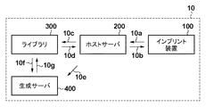
図1は、本発明の一側面としてのインプリントシステム10の構成を示す概略図である。インプリントシステム10は、基板上のインプリント材をモールドで成形するインプリント処理を行う。本実施形態では、インプリント材として、樹脂を使用し、樹脂硬化法として、紫外線の照射によって樹脂を硬化させる光硬化法を採用する。但し、本発明は、樹脂硬化法を限定するものではなく、熱によって樹脂を硬化させる熱硬化法を採用してもよい。インプリントシステム10は、インプリント装置(処理部)100と、ホストサーバ(制御部)200と、ライブラリ300と、生成サーバ(生成部)400とを有する。
<First Embodiment>
FIG. 1 is a schematic diagram showing a configuration of an
インプリント装置100は、基板上に樹脂を供給するためのディスペンサ(塗布部)を含み、インプリント処理を行う処理部として機能する。例えば、インプリント装置100は、ディスペンサから供給すべき樹脂の液滴の基板上における供給位置を示すマップ(樹脂塗布パターン、インプリントレシピ、ドロップレシピなどとも呼ばれる)に従って、基板上に樹脂の液滴の配列を形成する。そして、インプリント装置100は、基板上に供給された樹脂とモールドとを接触させた状態で樹脂を硬化させ、硬化した樹脂からモールドを引き離す(離型する)ことで基板上にパターンを形成する。また、インプリント装置100は、インプリント処理の結果やインプリント装置100の状態に関する情報を、ホストサーバ200に送信する機能10aを有している。
The
ホストサーバ200は、CPU、メモリ、HDDなどを含むコンピュータで構成され、インプリントシステム10の各部、即ち、インプリント装置100、ライブラリ300及び生成サーバ400を制御する。ホストサーバ200は、例えば、ディスペンサから供給すべき樹脂の液滴の基板上における供給位置を示すマップを制御する。また、ホストサーバ200は、インプリント処理を行う際のインプリント条件も制御する。ホストサーバ200は、インプリント処理に用いる、即ち、インプリント処理に適切なマップをインプリント装置100に送信する機能10bやライブラリ300に管理されているマップを参照(照会)する機能10cを有する。また、ホストサーバ200は、新たなマップの生成を指示するジョブやマップを生成するために必要となる情報を、生成サーバ400に送信する機能10eを有する。ここで、マップを生成するために必要となる情報とは、例えば、モールドのパターンの寸法、基板上に形成すべきパターンの残膜厚、基板面内情報、基板のショット領域のレイアウト情報などを含む。また、基板面内情報は、基板の面内における樹脂の揮発量の分布及び基板の面内における気流の分布を含む。
The
ライブラリ300は、CPU、メモリ、HDDなどを含むコンピュータで構成され、ディスペンサから供給すべき樹脂の液滴の基板上における供給位置を示すマップを管理(保管)する。ライブラリ300は、インプリント処理に適切なマップをホストサーバ200に送信する機能10dと、マップを生成するために必要となる情報を生成サーバ400に送信する機能10fとを有する。また、ライブラリ300は、保管している複数のマップの生成履歴及び選択履歴を解析する機能を有してもよい。
The
生成サーバ400は、CPU、メモリ、HDDなどを含むコンピュータで構成され、ホストサーバ200からのジョブに応じて、ディスペンサから供給すべき樹脂の液滴の基板上における供給位置を示すマップを生成する。この際、生成サーバ400は、モールドのパターンの寸法(モールドのパターンの設計値又は実測値)及び基板上に形成すべきパターンの残膜厚に基づいて、マップを生成する。更に、生成サーバ400は、基板の面内における樹脂の揮発量の分布及び基板の面内における気流の分布を含む基板面内情報、及び、基板のショット領域のレイアウト情報の少なくとも一方にも基づいて、マップを生成してもよい。生成サーバ400は、このようなマップを生成するために必要となる情報を、上述したように、ホストサーバ200やライブラリ300から取得する。また、生成サーバ400は、生成したマップをライブラリ300に送信する機能10gを有する。
The
なお、インプリントシステム10を構成する装置、サーバ及びライブラリ間での機能については図1に示す構成に限定されるものではなく、かかる機能を、図1に示す構成とは異なる装置、サーバ及びライブラリ間で実現してもよい。また、ホストサーバ200、ライブラリ300及び生成サーバ400は、インプリントシステム10の外部に設けることも可能である。但し、この場合にも、ホストサーバ200、ライブラリ300及び生成サーバ400とインプリント装置100とを接続して、インプリント処理に適切なマップをインプリント装置100に提供可能にする必要がある。
Note that the functions among the devices, servers, and libraries that make up the
インプリントシステム10では、基板上に形成すべきパターンや残膜厚に応じて、互いに異なる複数のマップをライブラリ300に予め保管している。インプリント装置100では、特に、ディスペンサの経時変化やモールドのパターンの経時変化によって、ディスペンサから供給すべき樹脂の液滴の基板上における供給位置を示すマップの変更が必要となる場合がある。このような場合、本実施形態では、新たなマップを生成することなく、ライブラリ300に管理されている複数のマップを参照してインプリント処理に適切なマップをインプリント装置100、即ち、ディスペンサに設定することができる。従って、マップを変更する際に、インプリント処理を停止させたり、モールドを交換したりすることが不要となるため、インプリント装置100の生産性(稼働率)を向上させることができる。本実施形態では、モールド及びディスペンサの少なくとも一方の経時変化によるインプリント処理の結果の変化を予測し、それに応じた複数のマップを予め管理しているため、予測可能な一定の経時変化やその変化幅に対して有効となる。なお、本実施形態では、突発的、或いは、局所的に発生する異常に対して、予め管理しているマップで最適なものがない場合には、インプリント処理の結果に応じて、新たなマップを生成する。
In the
本実施形態で想定している予測可能な経時変化とは、上述したように、モールドの経時変化やディスペンサの経時変化などである。モールドの経時変化は、モールドの洗浄などによるパターンの形状(凹凸形状)の変化、即ち、パターン寸法(線幅)、凹部と凸部との体積比率(Duty Cycle)、凹部の深さ(凸部の高さ)、凹凸のテーパー角、表面粗さ(Ra)などの変化を含む。また、ディスペンサの経時変化は、ディスペンサから吐出される樹脂の液滴量や着弾位置などの変化を含む。これらの経時変化によって、インプリント処理の結果、具体的には、基板上に形成されたパターンの線幅(CD:Critical Dimension)、残膜厚及び欠陥数が変化する。 As described above, the predictable change with time assumed in the present embodiment is a change with time of a mold, a change with time of a dispenser, and the like. Changes in the mold over time are changes in the shape of the pattern (uneven shape) due to cleaning of the mold, that is, pattern dimensions (line width), volume ratio between the recessed portion and the protruding portion (Duty Cycle), and the depth of the recessed portion (the protruding portion Height), taper angle of unevenness, surface roughness (Ra) and the like. The change with time of the dispenser includes changes in the amount of droplets of resin discharged from the dispenser and the landing position. Due to these temporal changes, as a result of the imprint process, specifically, the line width (CD: Critical Dimension), the remaining film thickness, and the number of defects of the pattern formed on the substrate change.
本実施形態では、インプリント処理の結果の変化に関する情報に基づいて、ライブラリ300で管理されている複数のマップからインプリント処理で用いる1つのマップを選択する。ここで、インプリント処理の結果の変化に関する情報は、モールドの使用履歴、ディスペンサの使用履歴及びインプリント処理の結果のうちの少なくとも1つを含む。また、インプリント処理の結果は、基板上に形成されたパターンの線幅、残膜厚及び欠陥数のうちの少なくとも1つを含む。
In the present embodiment, one map used in the imprint process is selected from a plurality of maps managed by the
更に、本実施形態では、インプリント処理の結果の変化に関する情報に加えて、インプリント処理を行う際のインプリント条件にも基づいて、ライブラリ300で管理されている複数のマップからインプリント処理で用いる1つのマップを選択してもよい。ここで、インプリント条件は、基板の面内における樹脂の揮発量の分布及び基板の面内における気流の分布を含む基板面内分布情報や基板のショット領域のレイアウト情報などを含む。
Furthermore, in the present embodiment, in addition to the information related to the change in the imprint processing result, the imprint processing can be performed from a plurality of maps managed in the
ライブラリ300で管理される複数のマップは、上述したように、インプリント処理の結果の変化を予測して生成される。ここで、ディスペンサから吐出される樹脂の液滴量の変化について考える。例えば、インプリント装置100に使用するディスペンサから吐出される樹脂の液滴量の実測値が5.0pLであるとする。この場合、液滴量の変化の範囲を±0.5pLと予測し、5.0±0.5pLの範囲において、0.1pLごとに、それに対応するマップ、即ち、11個のマップを生成してライブラリ300で管理する。
As described above, the plurality of maps managed by the
また、基板上に形成されたパターンの欠陥数の変化について考える。例えば、パターンの欠陥数の変化、即ち、増加によって必要となる樹脂の供給量の予測増加分1%の範囲において、0.1%ごとに、それに対応するマップ、即ち、11個のマップを生成してライブラリ300で管理する。
Also, consider the change in the number of defects in the pattern formed on the substrate. For example, in the range of 1% of the expected increase in the amount of resin required due to a change in the number of defects in the pattern, that is, an increase, a corresponding map, that is, 11 maps are generated every 0.1%. And managed by the
また、基板上に形成されたパターンの残膜厚の変化について考える。例えば、残膜厚の設計値が25.0nmであるとする。この場合、残膜厚の変化の範囲を±0.5nmと予測し、25.0±0.5nmの範囲において、0.1nmごとに、それに対応するマップ、即ち、11個のマップを生成してライブラリ300で管理する。
Also, consider the change in the remaining film thickness of the pattern formed on the substrate. For example, it is assumed that the design value of the remaining film thickness is 25.0 nm. In this case, the range of change in the remaining film thickness is predicted to be ± 0.5 nm, and a map corresponding to each 0.1 nm is generated in the range of 25.0 ± 0.5 nm, that is, 11 maps. Managed by the
また、基板上に形成されたパターンのCDの変化について考える。例えば、CDの設計値が50.0nmであるとする。この場合、CDの変化の範囲を±0.5nmと予測し、50.0±0.5nmの範囲において、0.1nmごとに、それに対応するマップ、即ち、11個のマップを生成してライブラリ300で管理する。 Consider the change in CD of the pattern formed on the substrate. For example, it is assumed that the design value of CD is 50.0 nm. In this case, the range of the CD change is predicted to be ± 0.5 nm, and a map corresponding to that, that is, 11 maps is generated every 0.1 nm in the range of 50.0 ± 0.5 nm, that is, a library. Manage at 300.
また、モールドのパターンの形状の変化について考える。例えば、モールドのパターンの変化によって必要となる樹脂の供給量の予測増加分1%の範囲において、0.1%ごとに、それに対応するマップ、即ち、11個のマップを生成してライブラリ300で管理する。
Also, consider changes in the shape of the mold pattern. For example, in the range of 1% of the expected increase in the amount of resin supply required due to changes in the mold pattern, a map corresponding to that, that is, 11 maps is generated every 0.1%, and the
また、上述したような変化のそれぞれに対してマップを生成及び管理するだけではなく、それらの組み合わせ(特に、同時に変化することが想定されるもの)について変化を予測し、それに対応するマップを生成及び管理してもよい。 In addition to generating and managing a map for each of the changes described above, a change is predicted for a combination of them (especially one that is assumed to change at the same time), and a corresponding map is generated. And may be managed.
インプリント装置100又は検査装置においてインプリント処理の結果の変化が検知された場合には、それに対応するマップをライブラリ300で管理されている複数のマップから選択してディスペンサに設定する。インプリント処理の結果の変化が改善(補正)されているかどうかの確認が必要な場合には、インプリント装置100又は検査装置を用いて、その変化が適正に改善されているかどうかを確認することができる。
When the
また、インプリント処理の結果の変化が検知されていない場合でも、インプリント処理の結果を定期的に検査し、その変化が検知されたら、それに対応するマップをライブラリ300で管理されている複数のマップから選択してディスペンサに設定してもよい。
Even if a change in the imprint processing result is not detected, the imprint processing result is periodically inspected. If the change is detected, a plurality of maps corresponding to the map are managed in the
図2は、インプリントシステム10におけるインプリント装置100の構成を示す概略図である。インプリント装置100は、半導体デバイスなどの製造プロセスで使用されるリソグラフィ装置であって、上述したように、基板上の樹脂にモールドのパターンを転写する。
FIG. 2 is a schematic diagram showing the configuration of the
インプリント装置100は、モールド101を保持するヘッド102と、照射部103と、基板104を保持するステージ105と、ディスペンサ110と、樹脂供給部111と、制御部112と、格納部113とを有する。
The
モールド101は、基板104に対向する面に、基板104に供給された樹脂120に転写すべきパターンが形成されたパターン領域101aを有する。モールド101は、例えば、矩形の外形形状を有する。モールド101は、基板上の樹脂120を硬化させるための紫外線を透過する材料、例えば、石英などで構成されている。
The
ヘッド102は、モールド101を真空吸引力又は静電気力によって保持(固定)する。ヘッド102は、モールド101をz軸方向に駆動する(移動させる)駆動機構を含む。ヘッド102は、基板上に供給された未硬化の樹脂120にモールド101を押印する機能、及び、基板上の硬化した樹脂120からモールド101を引き離す機能を有する。
The
照射部103は、基板上の樹脂120を硬化させる機能を有する。照射部103は、例えば、ハロゲンランプやLDEなどを含み、モールド101を介して、基板上の樹脂120に紫外線を照射する。
The
基板104は、モールド101のパターンが転写される基板であって、例えば、単結晶シリコン基板やSOI(Silicon on Insulator)基板などを含む。
The
ステージ105は、基板104を保持する基板チャックと、モールド101と基板104との位置合わせ(アライメント)を行うための駆動機構とを含む。かかる駆動機構は、例えば、粗動駆動系と微動駆動系とで構成され、x軸方向及びy軸方向に基板104を駆動する(移動させる)。また、かかる駆動機構は、x軸方向及びy軸方向だけではなく、z軸方向及びθ(z軸周りの回転)方向に基板104を駆動する機能や基板104の傾きを補正するためのチルト機能を備えていてもよい。
The
樹脂供給部111は、未硬化の樹脂120を保管するタンクを含む。樹脂供給部111は、供給管を介して、ディスペンサ110に対して未硬化の樹脂120を供給する。
The
ディスペンサ110は、例えば、基板104に対して樹脂120の液滴を吐出する複数のノズルを含み、基板上に樹脂120を供給(塗布)する。ディスペンサ110における樹脂120の供給量の単位は「滴」であり、樹脂120の1滴あたりの量は、サブピコリットルから数ピコリットルである。また、ディスペンサ110から樹脂120の液滴を滴下可能な基板上の位置は、数μmごとと決まっている。
For example, the
樹脂供給部111からディスペンサ110に樹脂120を供給しながらステージ105を駆動(スキャン駆動又はステップ駆動)させるとともに、ディスペンサ110から樹脂120の液滴を吐出することで、基板上に樹脂120の液滴の配列が形成される。
While supplying the
制御部112は、CPUやメモリなどを含み、インプリント装置100の全体(動作)を制御する。制御部112は、インプリント装置100の各部を制御して、インプリント処理を行う。また、制御部112は、ホストサーバ200に対して、必要に応じて、インプリント処理の結果、モールド101やディスペンサ110の使用履歴、温度や湿度の変化などの樹脂120の揮発に関わる情報などを送信する。制御部112は、ホストサーバ200から取得したマップを格納部113に格納する。
The
図3は、インプリントシステム10におけるホストサーバ200の構成を示す概略図である。ホストサーバ200は、結果管理部201と、結果判定部202と、マップ選択部203と、装置情報管理部204と、パターン情報管理部205と、設計情報管理部206と、条件管理部207と、装置履歴送信部208と、生成指示部209とを含む。
FIG. 3 is a schematic diagram showing the configuration of the
結果管理部201は、インプリント装置100から、インプリント処理時における装置条件、モールドの使用履歴、ディスペンサの使用履歴、インプリント処理の結果などを含むインプリント結果情報を取得し、それらを管理する。また、結果管理部201は、検査装置から、インプリント装置100によるインプリント処理の結果を解析した解析結果も取得して管理する。
The
結果判定部202は、結果管理部201で管理されているインプリント結果情報に基づいて、ディスペンサから供給すべき樹脂の液滴の基板上における供給位置を示すマップの変更が必要かどうかを判定する。
Based on the imprint result information managed by the
マップ選択部203は、結果判定部202によってマップの変更が必要であると判定された場合に、ライブラリ300で管理されている複数のマップから最適なマップを選択し、かかるマップをインプリント装置100に送信する。ライブラリ300で最適なマップが管理されていない場合には、マップ選択部203は、最適なマップに最も近いマップを選択し、かかるマップをインプリント装置100に送信する。この際、マップ選択部203は、生成指示部209に対して、新たなマップ(例えば、最適なマップ)の生成を指示するためのジョブを送信する。
When the
装置情報管理部204は、結果管理部201からインプリント結果情報を取得し、かかるインプリント処理情報から装置情報を抽出して管理する。同様に、パターン情報管理部205は、結果管理部201からインプリント結果情報を取得し、かかるインプリント処理情報からパターン情報を抽出して管理する。また、装置情報管理部204及びパターン情報管理部205は、管理している情報の変化を監視して経時変化情報として管理する。
The device
設計情報管理部206は、モールドのパターンの設計情報(設計値)やモールドのパターンの検査情報(実測値)を管理する。条件管理部207は、基板上に形成すべきパターンの残膜厚、基板のショット領域のレイアウト情報、モールドのパターンへの樹脂の充填時間、装置設定などを管理する。
The design
装置履歴送信部208は、装置情報管理部204及びパターン情報管理部205から経時変化情報を取得し、かかる経時変化情報を生成指示部209に送信する。
The device
生成指示部209は、マップ選択部203からのジョブに応じて、設計情報管理部206、条件管理部207及び装置履歴送信部208からマップの生成に必要な情報を取得し、かかる情報を、マップの生成を指示するジョブとともに、生成サーバ400に送信する。
The
また、生成指示部209は、マップ情報管理部301で管理されているマップ情報と、解析部303で管理されている選択履歴とを参照して、ライブラリ300で管理されているマップが不足していないか、或いは、不足する可能性がないかを判定する。マップが不足している、或いは、不足する可能性があると判定した場合には、生成指示部209は、新たなマップの生成を指示するジョブを生成サーバ400に送信する。
Also, the
図4は、インプリントシステム10におけるライブラリ300の構成を示す概略図である。ライブラリ300は、マップ情報管理部301と、マップ保存部302と、解析部303とを有する。
FIG. 4 is a schematic diagram showing the configuration of the
マップ情報管理部301は、ライブラリ300で管理しているマップが生成された際の生成条件に関するマップ情報を管理する。マップ情報管理部301は、ホストサーバ200からのライブラリ300で管理されているマップの照会に応じて、マップ情報を参照して該当するマップを管理しているかどうかを判定する。該当するマップを管理している場合には、マップ情報管理部301は、かかるマップをホストサーバ200に送信する。また、マップ情報管理部301は、ホストサーバ200からマップの生成を指示するジョブを取得した場合に、マップの生成に必要な情報を生成サーバ400に送信する。更に、マップ情報管理部301は、生成サーバ400で生成された新たなマップのマップ情報を生成サーバ400から取得して管理する。
The map
マップ保存部302は、インプリント装置100に送信可能なファイル形式でマップを保存(保管)する。マップ保存部302は、マップ情報管理部301を介して、ホストサーバ200にマップを送信するとともに、生成サーバ400で生成されたマップを保存する。
The
解析部303は、ホストサーバ200からマップの選択結果を取得し、マップの選択履歴として管理する。
The
図5は、インプリントシステム10における生成サーバ400の構成を示す概略図である。生成サーバ400は、設計情報設定部401と、パラメータ設定部402と、レイアウト情報設定部403と、装置履歴設定部404と、装置変化管理部405と、パターン変化管理部406と、液滴数算出部407と、決定部408と、出力部409とを含む。
FIG. 5 is a schematic diagram showing the configuration of the
設計情報設定部401は、モールド101に形成されているパターンの設計情報をホストサーバ200から取得し、かかる設計情報を設定(入力)する。パラメータ設定部402は、モールド101の凹部の深さ(凸部の高さ)、基板上に形成するパターンの残膜厚などの設定情報をホストサーバ200から取得し、かかる設定情報を設定(入力)する。また、パラメータ設定部402は、基板上の樹脂120の拡がりに関する情報、モールド101のパターンへの樹脂120の充填時間、基板上で必要な樹脂120の液滴の間隔などの制約条件も設定(入力)する。
The design
レイアウト情報設定部403は、基板104のショット領域のレイアウト情報をホストサーバ200から取得して、かかるレイアウト情報を設定(入力)する。装置履歴設定部404は、モールド101やディスペンサ110の使用履歴などから算出される樹脂120の液滴補正量及び液滴の基板上における供給位置を決定するための分布情報を、ホストサーバ200から取得し、かかる分布情報を設定(入力)する。
The layout
装置変化管理部405は、ディスペンサ110の使用履歴から算出される樹脂120の液滴補正量及び液滴の基板上における供給位置を決定するための分布情報を管理(提供)する。パターン変化管理部406は、モールド101の使用履歴から算出される樹脂120の液滴補正量及び液滴の基板上における供給位置を決定するための分布情報を管理(提供)する。
The device
液滴数算出部407は、インプリント処理を行う基板上のインプリント領域に供給すべき樹脂120の供給量、即ち、樹脂120の液滴数を算出する。液滴数算出部407は、例えば、設計情報設定部401及びパラメータ設定部402で設定された情報、装置変化管理部405及びパターン変化管理部406で管理された情報、液滴補正量などに基づいて、液滴数を算出する。
The droplet
決定部408は、基板上における樹脂120の液滴の配列、即ち、樹脂120の液滴の供給位置を決定する。決定部408は、例えば、設計情報設定部401及びパラメータ設定部402で設定された情報、装置変化管理部405及びパターン変化管理部406で管理された情報、液滴数算出部407で算出された液滴数、液滴補正量などに基づいて、供給位置を決定する。
The
出力部409は、決定部408で決定された基板上における樹脂120の液滴の供給位置に基づいて、指定された形式でマップを出力する。出力部409で出力されたマップは、ライブラリ300に送信されて管理される。
The
インプリントシステム10におけるインプリント処理について詳細に説明する。図6は、インプリントシステム10におけるインプリント処理を説明するためのフローチャートである。インプリント処理は、上述したように、ホストサーバ200がインプリント装置100、ライブラリ300及び生成サーバ400を統括的に制御し、制御部112がインプリント装置100の各部を統括的に制御することで行われる。
The imprint process in the
S100では、基板104に形成すべきパターンを形成可能なモールド101をインプリント装置100に搬入し、かかるモールド101をヘッド102に保持させる。モールド101は、例えば、フォトマスクに用いる透明な石英基板に、設計情報に対応する凹凸のパターンが形成されたものである。モールド101には、一般的に、そのパターンを識別するためのIDが設定されている。
In S <b> 100, a
S101では、ヘッド102に保持されたモールド101のIDを読み取り、かかるIDに基づいて、ホストサーバ200から、モールド101のパターン情報、具体的には、パターンの配置、線幅及び密度、或いは、パターンの形状の計測結果などを取得する。
In S101, the ID of the
S102では、ホストサーバ200から、インプリント装置100に搭載されたディスペンサ110に関するディスペンサ情報を取得する。ここで、ディスペンサ情報は、例えば、ディスペンサ110の種類及びノズル数、吐出性能である平均吐出量、ノズルごとの吐出量のばらつき、基板上での着弾位置のばらつきなどを含む。ディスペンサ110には、一般には、そのディスペンサ情報を識別するためのIDが設定されているため、かかるIDを読み取ることで、インプリント装置100に搭載されたディスペンサ110に関するディスペンサ情報を取得することができる。
In S <b> 102, dispenser information related to the
S103では、基板104をインプリント装置100に搬入し、図7(a)に示すように、かかる基板104をステージ105に保持させる。
In step S103, the
S104では、ライブラリ300で管理されている複数のマップからインプリント処理に用いる1つのマップを選択する。具体的には、S101及びS102のそれぞれで取得したパターン情報及びディスペンサ情報、モールド101の使用履歴、ディスペンサ110の使用履歴、及び、インプリント処理の結果のうちの少なくとも1つに基づいて、マップを選択する。上述したように、マップは、ディスペンサ110から供給すべき樹脂120の液滴の基板上における供給位置を示すものである。かかるマップは、本実施形態では、生成サーバ400で生成され、目標とする充填時間に対して、欠陥や残膜厚の異常のないインプリント処理が可能なように最適化されている。
In S104, one map used for imprint processing is selected from a plurality of maps managed by the
S105では、基板のショット領域のうち、インプリント処理が行われていないショット領域を対象ショット領域として指定する。ここで、ショット領域とは、1回のインプリント処理でパターンが形成される領域を意味するものとする。また、対象ショット領域とは、これからインプリント処理を行うショット領域を意味するものとする。本実施形態では、例えば、図7(b)に示すように、基板104において連続するショット領域S1、S2、S3、S4、・・・の順にインプリント処理を行う。但し、インプリント処理の順序は、図7(b)に示すようなものに限定されるものではなく、千鳥格子順であってもよいし、ランダムであってもよい。 In S105, a shot area that has not been subjected to imprint processing among the shot areas of the substrate is designated as a target shot area. Here, the shot area means an area where a pattern is formed by one imprint process. Further, the target shot area means a shot area where imprint processing will be performed from now on. In this embodiment, for example, as shown in FIG. 7B, imprint processing is performed in the order of shot areas S1, S2, S3, S4,. However, the order of the imprint processing is not limited to that shown in FIG. 7B, and may be in a houndstooth order or random.
S106では、ディスペンサ110によって、基板上に樹脂120を供給する。この際、ディスペンサ110は、図7(c)に示すように、S104で選択されたマップに従って、ステージ105の移動に応じて基板上に樹脂120の液滴を順次吐出する。
In S <b> 106, the
S107では、押印処理を行う。具体的には、まず、図8(a)に示すように、樹脂120が供給された基板104に対して、モールド101を近接させる。次いで、図8(b)に示すように、モールド101と基板104との位置合わせを行いながら、モールド101と基板上の樹脂120とを接触させる。そして、モールド101のパターンに樹脂120が充填されるまで、かかる状態を維持する。モールド101と基板上の樹脂120とを接触させた初期段階では、モールド101のパターンへの樹脂120の充填が不十分であるため、パターンの隅に充填欠陥を生じている。但し、時間が経過していくにつれて、モールド101のパターンの隅々まで樹脂120が充填され、充填欠陥が減少する。
In S107, a stamping process is performed. Specifically, first, as shown in FIG. 8A, the
S108では、硬化処理を行う。具体的には、モールド101のパターンに樹脂120を十分充填させた後、図8(c)に示すように、照射部103によって、モールド101の裏面から樹脂120に紫外線を所定時間照射して、基板上の樹脂120を硬化させる。
In S108, a curing process is performed. Specifically, after sufficiently filling the pattern of the
S109では、離型処理を行う。具体的には、図8(d)に示すように、基板上の硬化した樹脂120からモールド101を引き離す。これにより、基板上にモールド101のパターンに対応する樹脂パターン121が形成される。
In S109, a mold release process is performed. Specifically, as shown in FIG. 8D, the
S110では、S104で選択したマップの変更が必要であるかどうかを判定する。かかる判定の基準は、例えば、インプリント処理の結果の変化、即ち、基板上に形成されたパターンのCD、残膜厚及び欠陥数などの変化である。このような変化は、ディスペンサ110から吐出された樹脂120の液滴の液滴量や着弾位置のずれ、モールド101のパターンの寸法の変化、モールド101の使用限度回数のオーバーなどによって生じる。また、このような変化は、モールド101の押印力や離型力の変動、押印処理におけるモールド101と基板104との間のゴミの挟み込みなどによっても生じる。インプリント処理の結果の変化は、インプリント装置100や外部の検査装置で検知することが可能である。インプリント処理の結果の変化が検知された場合には、パターンの転写不良(製品不良)を招く可能性があるため、インプリント処理を停止してもよい。マップの変更が必要である場合には、新たなマップを選択するために、S104に移行する。一方、マップの変更が必要でない場合には、S111に移行する。
In S110, it is determined whether or not the map selected in S104 needs to be changed. The criterion for such determination is, for example, a change in the result of the imprint process, that is, a change in the CD formed on the substrate, the remaining film thickness, the number of defects, and the like. Such a change is caused by the amount of droplets or landing positions of the
S111では、基板104の全てのショット領域にインプリント処理を行ったかどうかを判定する。基板104の全てのショット領域にインプリント処理を行っていない場合には、インプリント処理が行われていないショット領域を対象ショット領域として指定するために、S105に移行する。S105からS111までの処理を繰り返すことで、基板104の全てのショット領域に樹脂パターン121が形成される。一方、基板104の全てのショット領域にインプリント処理を行った場合には、S112に移行する。
In S <b> 111, it is determined whether imprint processing has been performed on all shot regions of the
S112では、全てのショット領域にインプリント処理が行われた基板104を、インプリント装置100から搬出する。インプリント装置100から搬出された基板104は、樹脂パターン121をマスクとして下層側が加工(例えば、エッチング)される。半導体デバイスを製造する際には、これらの処理がプロセスのレイヤごとに繰り返される。
In S <b> 112, the
ここで、同一のモールド101及びディスペンサ110を用いて、次のロットの基板104にインプリント処理を行う場合を考える。このような場合には、かかるインプリント処理に用いるマップとして、前のロットで使用していたマップ(同一のマップ)が選択される。
Here, consider a case where imprint processing is performed on the
また、マップの変更が必要であるかどうかの判定(S110)では、モールド101の洗浄が必要であるかどうかも判定してもよい。モールド101の洗浄が必要でない場合には、かかるモールド101の使用履歴に応じて、ライブラリ300で管理されている複数のマップから最適なマップが選択される。この際、最適なマップがライブラリ300で管理されていない場合には、かかるマップの生成を指示するジョブがホストサーバ200から生成サーバ400に送信される。そして、かかるジョブに応じて生成サーバ400で生成されたマップがライブラリ300で保管されるとともに、ホストサーバ200を介して、インプリント装置100に送信される。
In the determination of whether or not the map needs to be changed (S110), it may be determined whether or not the
一方、モールド101の洗浄が必要である場合には、インプリント処理を停止して、ヘッド102からモールド101を取り外す。但し、この場合には、新たなモールド101をヘッド102に保持させて、ライブラリ300で管理されている複数のマップから新たなモールド101に対応するマップを選択することで、インプリント処理を停止する期間を最小限に抑えるとよい。
On the other hand, when the
ヘッド102から取り外されたモールド101は、モールド洗浄装置に搬入して洗浄される。モールド洗浄装置は、例えば、モールド101に付着するゴミや汚れに対して、薬液や純水を使用してウェット洗浄する洗浄装置を用いてもよいし、エキシマレーザやプラズマなどを使用してドライ洗浄する洗浄装置を用いてもよい。モールド101の洗浄が終了したら、かかるモールド101の使用履歴に洗浄したことが追加される。
The
また、モールド101を洗浄すると、そのパターンが摩耗し、パターンの形状に変化が生じる可能性がある。そこで、洗浄したモールド101のパターンの形状(凹凸形状)を計測する必要がある。具体的には、モールド101のパターンの形状として、モールド101のパターン寸法、凹部と凸部との体積比率(Duty Cycle)、凹部の深さ(凸部の高さ)、凹凸のテーパー角、表面粗さ(Ra)などを計測する。このようなモールド101のパターンの形状を表す物理量は、一般的な寸法計測装置、高さ計測装置、粗さ計測装置を用いて計測することができる。
Further, when the
例えば、モールド101のパターンの線幅及びDuty Cycleを計測する際には、電子ビーム方式の寸法計測装置(CD−SEM)を用いればよい。モールド101のパターンがライン(凹部)とスペース(凸部)との繰り返しパターンである場合、ラインの幅及びスペースの幅を複数箇所について計測し、モールド101を洗浄する前と比べて差分があれば、モールド101のパターンの線幅が変化したことになる。Duty Cycleについては、ラインとスペースとの比率から求めることができる。
For example, when measuring the line width and duty cycle of the pattern of the
また、モールド101の、凹部の深さ、凹凸のテーパー角、表面粗さを計測する際には、AFMや共焦点顕微鏡を用いればよい。これらは、モールド101のパターンを直接計測することで求めてもよいし、モールド101のパターンの外側に設けた計測用パターンを計測することで間接的に求めてもよい。
Further, when measuring the depth of the concave portion, the taper angle of the concave and convex portions, and the surface roughness of the
モールド101を洗浄すると、モールド101の表面(パターン領域101a)が一定量摩耗して薄くなることに加えて、そのパターンに応じて摩耗量の分布も発生する。例えば、モールド101のパターンがライン(凹部)とスペース(凸部)との繰り返しパターンである場合、洗浄によって、凹部の幅が太くなり、凸部の幅が狭くなるため、凹部の体積比率が増加する。また、凸部がより摩耗する場合には、凸部の高さがより小さくなり、凹凸のテーパー角は小さくなる。モールド101の表面における凹凸が小さくなる場合には、表面粗さが小さくなる。
When the
モールド101のパターン(凹凸形状)を表す物理量は、モールド101のパターンを直接計測するのではなく、洗浄後に行われるテストインプリント処理により得られる樹脂パターンを計測することで求めることも可能である。テストインプリント処理により得られる樹脂パターンを計測する場合には、樹脂パターンを切り出してその断面を計測してもよい。
The physical quantity representing the pattern (uneven shape) of the
このようにして計測されたモールド101のパターンの寸法は、ホストサーバ200に送信され、モールド101のパターンの寸法の実測値として管理される。また、洗浄したモールド101を用いてインプリント処理を行う場合には、モールド101を洗浄したことを含むモールド101の履歴情報に基づいて、新たなマップが選択又は生成され、インプリント処理に用いられる。
The dimension of the pattern of the
図9を参照して、ディスペンサ110から供給すべき樹脂120の液滴の基板上における供給位置や供給量を示すマップを生成する処理について詳細に説明する。本実施形態では、上述したように、生成サーバ400においてマップを生成し、かかるマップをライブラリ300で管理する。但し、インプリントシステム10の外部の情報処理装置などでマップを生成し、かかるマップをライブラリ300で管理してもよい。
With reference to FIG. 9, a process for generating a map indicating the supply position and supply amount of the droplets of the
S200では、モールド101のパターンの設計情報や装置情報から基板上の各領域に必要な樹脂120の供給量(塗布量)を算出した供給量分布を取得する。供給量分布は、ホストサーバ200における装置情報管理部204、パターン情報管理部205、設計情報管理部206、条件管理部207及び生成指示部209からの情報に基づいて算出される。ここで、かかる情報は、モールド101のパターンの寸法、基板上に形成すべきパターンの残膜厚、基板104の面内における樹脂の揮発量の分布や気流の分布を含む基板面内分布情報、基板104のショット領域のレイアウト情報などを含む。
In S200, a supply amount distribution obtained by calculating the supply amount (application amount) of the
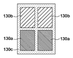
本実施形態では、供給量分布情報として、図10に示すように、基板上における樹脂120の供給量分布を濃淡の多値情報に変換した画像データを用いる。図10を参照するに、領域130a乃至130cは、モールド101のパターンの位置、形状及び深さなどに基づいて算出された濃淡を示している。領域130aは、パターンの深さが深く、樹脂120の必要体積が大きい領域を示している。領域130bは、パターンの深さが浅く、樹脂120の必要体積が領域130aよりも小さい領域を示している。領域130cは、パターンがなく、樹脂120の必要体積が領域130bよりも小さい領域を示している。
In the present embodiment, as the supply amount distribution information, as shown in FIG. 10, image data obtained by converting the supply amount distribution of the
S201では、S200で取得された供給量分布情報やディスペンサ110から吐出される樹脂120の液滴のサイズ(例えば、液滴量)に基づいて、基板上のインプリント領域内に必要な樹脂120の液滴数を算出する。
In S201, based on the supply amount distribution information acquired in S200 and the size of the droplets of the
S202では、S200で取得された供給量分布及びS201で算出された液滴数に基づいて、ディスペンサ110から供給すべき樹脂120の液滴の基板上における供給位置や供給量を示すマップを生成する。具体的には、まず、S200で取得した供給量分布情報から多値分布データを生成する。次いで、かかる多値分布データをハーフトーン処理によって2値化して、ディスペンサ110における樹脂120の液滴の吐出及び非吐出を指定する情報に変換することでマップを生成する。ハーフトーン処理としては、公知技術である誤差拡散法を用いることができる。図11は、S202で生成されたマップの一例を示す図である。図11では、基板上における樹脂120の液滴の供給位置(液滴の吐出)を黒点140aで示し、基板上における樹脂120の液滴の非供給位置(液滴の非吐出)を白点140bで示している。
In S202, based on the supply amount distribution acquired in S200 and the number of droplets calculated in S201, a map indicating the supply position and supply amount of the droplets of the
S203では、S202で生成されたマップ、即ち、ディスペンサ110から供給すべき樹脂120の液滴の基板上における供給位置を示すマップをライブラリ300に送信する。かかるマップは、ライブラリ300におけるマップ保存部302に保存される。
In S <b> 203, the map generated in S <b> 202, that is, a map indicating the supply position on the substrate of the droplets of the
本実施形態では、マップを生成する処理において、ハーフトーン処理として誤差拡散法を用いているが、これに限定されるものではなく、ディザ法などの他の手法も適用可能である。また、ハーフトーン処理以外の手法でも、基板上の必要な領域に必要量の液滴を配置できる手法であれば適用可能である。 In the present embodiment, the error diffusion method is used as the halftone processing in the process of generating the map. However, the present invention is not limited to this, and other methods such as a dither method can be applied. Also, a technique other than the halftone process can be applied as long as it can arrange a necessary amount of droplets in a necessary area on the substrate.
また、本実施形態では、マップとして、樹脂120の液滴の吐出及び非吐出を指定する2値情報に変換したデータを用いているが、データの形式を特に限定するものではない。例えば、マップとして、基板上における樹脂120の液滴の供給位置を基板上の相対位置座標で表した数値データを用いることも可能である。また、マップには、基板上における樹脂120の各液滴の量(液滴量)に関する情報を追加することも可能である。
In this embodiment, data converted into binary information designating ejection and non-ejection of droplets of the
本実施形態におけるインプリントシステム10では、モールド101及びディスペンサ110の少なくとも一方の経時変化によるインプリント処理の結果の変化を予測し、それに応じた複数のマップを予め管理している。従って、インプリント処理の結果が変化に応じて、新たなマップを生成することなく、ライブラリ300に管理されている複数のマップからインプリント処理に適切なマップを選択することができる。これにより、マップを変更する際に、インプリント処理を停止させたり、モールド101を交換したりすることが不要となるため、インプリント装置100の生産性(稼働率)を向上させることができる。
In the
<第2の実施形態>
図12を参照して、モールド101やディスペンサ110などの経時変化から変化が予測されるインプリント処理の結果の範囲における複数のマップを生成する処理について説明する。本実施形態では、上述したように、生成サーバ400においてマップを生成し、かかるマップをライブラリ300で管理する。但し、インプリントシステム10の外部の情報処理装置などでマップを生成し、かかるマップをライブラリ300で管理してもよい。
<Second Embodiment>
With reference to FIG. 12, a process for generating a plurality of maps in the range of the result of the imprint process in which a change is predicted from a change with time such as the
S300では、ホストサーバ200から、モールド101のパターン情報、具体的には、パターンの配置、線幅及び密度、或いは、パターンの形状の計測結果などを取得する。S301では、ホストサーバ200から、インプリント装置100に搭載されたディスペンサ110に関するディスペンサ情報を取得する。
In S300, the pattern information of the
S302では、ホストサーバ200から、インプリント処理を行う際のインプリント条件を取得する。S303では、ホストサーバ200から、基板104のショット領域のレイアウト情報を取得する。S303では、ホストサーバ200から、モールド101の使用履歴及びディスペンサ110の使用履歴を取得する。
In S <b> 302, the imprint condition for performing the imprint process is acquired from the
S305では、S300乃至S303のそれぞれで取得したパターン情報、ディスペンサ情報、インプリント条件、モールド101の使用履歴及びディスペンサ110の使用履歴に基づいて、インプリント処理の結果の変化の範囲を予測する。この際、インプリント処理の結果の変化の範囲内において、マップを生成すべき複数の結果を設定する。また、本実施形態では、現在のインプリント処理の結果(即ち、現在のインプリント装置100の状態)を中心として、その変化の範囲を予測する。
In S305, the range of change in the imprint processing result is predicted based on the pattern information, dispenser information, imprint conditions, use history of the
S306では、S305で予測されたインプリント処理の結果の変化の範囲内におけるマップを生成する。本実施形態では、インプリント処理の変化の範囲内で設定された複数の結果のうちの1つの結果に対応するマップを生成する。なお、マップの生成については、第1の実施形態と同様であるため、ここでの詳細な説明は省略する。 In S306, a map is generated within the range of change in the result of the imprint process predicted in S305. In the present embodiment, a map corresponding to one result among a plurality of results set within the range of change in imprint processing is generated. The map generation is the same as in the first embodiment, and a detailed description thereof is omitted here.
S307では、S306で生成されたマップ、即ち、ディスペンサ110から供給すべき樹脂120の液滴の基板上における供給位置を示すマップをライブラリ300に送信する。かかるマップは、ライブラリ300におけるマップ保存部302に保存される。
In S307, the map generated in S306, that is, the map indicating the supply position on the substrate of the droplets of the
S308では、S305で予測されたインプリント処理の結果の範囲内における複数のマップの全て、即ち、インプリント処理の変化の範囲内で設定された複数の結果のそれぞれに対応するマップを生成しかたどうかを判定する。複数のマップの全てを生成していない場合には、インプリント処理の結果の範囲内における新たなマップを生成するために、S306に移行する。一方、複数のマップの全てを生成している場合には、処理を終了する。 In S308, whether or not to generate maps corresponding to all of the plurality of maps within the range of the imprint processing result predicted in S305, that is, each of the plurality of results set within the range of change of the imprint processing. Determine. If all of the plurality of maps have not been generated, the process proceeds to S306 in order to generate a new map within the range of the result of the imprint process. On the other hand, if all of the plurality of maps have been generated, the process ends.
また、インプリントシステム10では、インプリント処理の結果の変化に応じて、ディスペンサ110から供給すべき樹脂120の液滴の基板上における供給位置を示すマップを変更するとともに、ライブラリ300で管理するマップを更新することも可能である。図13を参照して、インプリント処理の結果の変化に対するマップの変更及び更新に関する処理について説明する。かかる処理は、ホストサーバ200がインプリント装置100、ライブラリ300及び生成サーバ400を統括的に制御することで行われる。
Further, in the
S401では、インプリント処理の結果の変化が検知されたかどうかを判定する。上述したように、インプリント処理の結果の変化は、インプリント装置100や外部の検査装置で検知することが可能である。インプリント処理の結果の変化が検知されていない場合には、インプリント処理の結果の変化が検知されるまで待機する。一方、インプリント処理の結果の変化が検知された場合には、S402に移行する。
In step S401, it is determined whether a change in the imprint processing result has been detected. As described above, a change in the imprint processing result can be detected by the
S402では、S401で検知されたインプリント処理の結果の変化に応じて、かかるインプリント処理の結果に対応する最適なマップ(即ち、次のインプリント処理で用いるべきマップ)がライブラリ300で管理されているかどうかを判定する。インプリント処理の結果に対応するマップがライブラリ300で管理されていない場合には、S403に移行する。一方、インプリント処理の結果に対応するマップがライブラリ300で管理されている場合には、S404に移行する。
In S402, in accordance with the change in the imprint processing result detected in S401, an optimal map corresponding to the imprint processing result (that is, a map to be used in the next imprint processing) is managed by the
S403では、生成サーバ400に対して、インプリント処理の結果に対応するマップの生成を指示する。生成サーバ400で生成されたマップは、ライブラリ300に送信されて管理される。
In step S403, the
S404では、ライブラリ300で管理されている複数のマップから、インプリント処理の結果に対応する最適なマップを、次のインプリント処理で用いるマップとして選択する。
In S404, an optimum map corresponding to the result of the imprint process is selected from the plurality of maps managed by the
S405では、S404でのマップの選択結果から、予測されたインプリント処理の結果の変化の範囲(予測範囲)にずれが発生しているか、即ち、インプリント処理の結果の変化の範囲が(例えば、第1範囲から第2範囲に)変動しているかどうかを判定する。予測範囲にずれが発生している場合には、S406に移行する。一方、予測範囲にずれが発生しない場合には、処理を終了する。 In S405, whether or not there is a deviation in the predicted change range (prediction range) of the imprint process result from the map selection result in S404, that is, the change range of the imprint process result (for example, , It is determined whether there is a change from the first range to the second range. If there is a deviation in the prediction range, the process proceeds to S406. On the other hand, if there is no deviation in the prediction range, the process ends.
S406では、予測範囲のずれに応じて、インプリント処理の結果の範囲(例えば、第2範囲)を新たに予測し、生成サーバ400に対して、かかる範囲内における複数のマップの生成を指示する。本実施形態では、S404で選択されたマップに対応するインプリント処理の結果を中心とする新たな予測範囲内の複数の結果のそれぞれに対応するマップの生成を指示する。生成サーバ400で生成された複数のマップは、ライブラリ300に送信されて管理される。この際、生成サーバ400による新たな予測範囲内における複数のマップの生成を、インプリント装置100によるインプリント処理と並行して行うとよい。これにより、インプリント処理の結果の変化が新たに検知されたときに、新たなマップを生成すること、即ち、インプリント処理を停止させることが不要となるため、インプリント装置100の生産性(稼働率)を向上させることができる。また、これまでの予測範囲(第1範囲)と新たな予測範囲(第2範囲)とは、一部重なり合っていてもよい。
In S406, a range of the imprint processing result (for example, the second range) is newly predicted according to the shift of the prediction range, and the
このように、本実施形態では、予測されたインプリント処理の結果の変化の範囲(予測範囲)にずれが発生した場合には、新たな予測範囲内の複数の結果のそれぞれに対応するマップを生成し、かかるマップをライブラリ300で管理している。換言すれば、インプリント処理の結果の変化に応じて、ライブラリ300で管理しているマップを更新している。従って、インプリント処理の結果が変化に応じて、新たなマップを生成することなく、ライブラリ300に管理されている複数のマップからインプリント処理に適切なマップを選択することができる。これにより、マップを変更する際に、インプリント処理を停止させたり、モールド101を交換したりすることが不要となるため、インプリント装置100の生産性(稼働率)を向上させることができる。
As described above, in the present embodiment, when a shift occurs in the range of change in the predicted imprint processing result (prediction range), a map corresponding to each of the plurality of results in the new prediction range is displayed. The map is generated and managed by the
<第3の実施形態>
図14は、本発明の一側面としてのインプリントシステム11の構成を示す概略図である。インプリントシステム11は、インプリントシステム10と同様な構成を有し、基板上のインプリント材をモールドで成形するインプリント処理を行う。具体的には、インプリントシステム11は、インプリント装置100、ホストサーバ200、ライブラリ300及び生成サーバ400に加えて、他のインプリント装置100A及び100Bを有する。インプリント装置100、100A及び100Bは、ホストサーバ200によって制御されている。
<Third Embodiment>
FIG. 14 is a schematic diagram showing a configuration of an
インプリント装置100、100A及び100Bのそれぞれで同時にインプリント処理を行う場合を考える。この場合、ホストサーバ200は、インプリント装置100、100A及び100Bのそれぞれについて、ライブラリ300で管理されている複数のマップからインプリント処理に用いる1つのマップを選択する。これは、インプリント装置100、100A及び100Bで使用されるモールド101及びディスペンサ110が装置ごとに異なる(別である)からである。なお、インプリント装置100、100A及び100Bで使用されるモールド101及びディスペンサ110に実質的に差がない場合には、インプリント装置100、100A及び100Bで同一のマップを選択してもよい。但し、インプリント装置100、100A及び100Bの間でインプリント処理の結果に変化に差が生じた場合には、インプリント装置100、100A及び100Bのそれぞれについて、最適なマップを選択することが必要となる。
Consider a case where imprint processing is simultaneously performed in each of the
また、本実施形態では、ライブラリ300は、マップを管理する際に、インプリント装置100、100A及び100Bのそれぞれを識別して管理する。換言すれば、インプリント装置100、100A及び100Bごとに、予測範囲内におけるマップを管理する。これにより、インプリント装置100、100A及び100Bの間でインプリント処理の結果に変化に差が生じた場合にも、最適なマップを選択できる可能性を高めることができる。
In the present embodiment, the
また、インプリント装置100、100A及び100Bのそれぞれの予測範囲については、他のインプリント装置におけるマップの選択結果を参照して設定することも可能である。ここで、インプリント装置100で使用されるモールド101の洗浄回数がインプリント装置100Aで使用されるモールド101の洗浄回数よりも先行して進んでいた場合を考える。この場合、インプリント装置100におけるマップの選択履歴から、インプリント装置100Aにおいて選択されるマップを予測することが可能となる。例えば、モールド101の洗浄に対して、予め予測されているモールド101のパターンの寸法の変化と、インプリント装置100で実際に使用しているモールド101のパターンの寸法の変化との間に差分があることがある。そこで、この差分をインプリント装置100Bにおける予測範囲に反映させる。これにより、インプリント装置100Bで使用されるモールド101の洗浄回数がインプリント装置100Aで使用されているモールド101の洗浄回数に達したときに、最適なマップを選択できる可能性を高めることができる。
In addition, the prediction ranges of the
複数のインプリント装置を有するインプリントシステム11においては、各インプリント装置におけるマップの選択結果を、他のインプリント装置の予測範囲に反映させることで、予測範囲の精度を高めることが可能となる。
In the
また、本実施形態では、3つのインプリント装置100、100A及び100Bを1つのホストサーバ200で制御している。このように、複数のインプリント装置を1つのホストサーバで制御する場合にはかかるホストサーバの負荷が大きくなることが想定される。従って、ディスペンサが供給すべき樹脂の液滴の基板上における供給位置を示すマップを選択する機能を各インプリント装置が有していてもよい。この場合、ホストサーバは、各インプリント装置におけるマップの選択履歴を管理することになる。
In the present embodiment, the three
このように、インプリントシステム11では、複数のインプリント装置を有していても、各インプリント装置を識別して複数のマップを予め管理している。従って、各インプリント装置について、インプリント処理の結果が変化に応じて、新たなマップを生成することなく、ライブラリ300に管理されている複数のマップからインプリント処理に適切なマップを選択することができる。これにより、マップを変更する際に、インプリント処理を停止させたり、モールド101を交換したりすることが不要となるため、インプリント装置100の生産性(稼働率)を向上させることができる。
As described above, even if the
<第4の実施形態>
物品としてのデバイス(半導体デバイス、磁気記憶媒体、液晶表示素子等)の製造方法について説明する。かかる製造方法は、インプリントシステム10又は11を用いてパターンを基板(ウエハ、ガラスプレート、フィルム状基板等)に形成する工程を含む。かかる製造方法は、パターンを形成された基板を処理する工程を更に含む。当該処理ステップは、当該パターンの残膜を除去するステップを含みうる。また、当該パターンをマスクとして基板をエッチングするステップなどの周知の他のステップを含みうる。本実施形態における物品の製造方法は、従来に比べて、物品の性能、品質、生産性及び生産コストの少なくとも1つにおいて有利である。
<Fourth Embodiment>
A method for manufacturing a device (semiconductor device, magnetic storage medium, liquid crystal display element, etc.) as an article will be described. Such a manufacturing method includes a step of forming a pattern on a substrate (wafer, glass plate, film-like substrate, etc.) using the
以上、本発明の好ましい実施形態について説明したが、本発明はこれらの実施形態に限定されないことはいうまでもなく、その要旨の範囲内で種々の変形及び変更が可能である。 As mentioned above, although preferable embodiment of this invention was described, it cannot be overemphasized that this invention is not limited to these embodiment, A various deformation | transformation and change are possible within the range of the summary.
10:インプリントシステム 100:インプリント装置 200:ホストサーバ 300:ライブラリ 400:生成サーバ 10: imprint system 100: imprint apparatus 200: host server 300: library 400: generation server
Claims (15)
前記基板上に前記インプリント材の液滴を供給するディスペンサを含み、前記インプリント材を硬化させるインプリント処理を行う処理部と、
前記ディスペンサから供給すべき液滴の前記基板上における供給位置及び供給量の少なくとも一方を示す、互いに異なる複数の分布情報を管理するライブラリと、
前記モールド及び前記ディスペンサの少なくとも一方の経時変化による前記インプリント処理の結果の変化に関する情報に基づいて、前記ライブラリで管理されている前記複数の分布情報から前記インプリント処理に用いる1つの分布情報を選択する制御部と、
を有し、
前記複数の分布情報のそれぞれは、前記経時変化から変化が予測されるインプリント処理の結果の範囲内の複数の結果のそれぞれに対応する、液滴の前記基板上における供給位置及び供給量の少なくとも一方を示すことを特徴とするインプリントシステム。 An imprint system for performing an imprint process for curing the imprint material in a state where the imprint material on the substrate and the mold are in contact with each other ,
A processing unit that includes a dispenser that supplies droplets of the imprint material on the substrate, and that performs an imprint process for curing the imprint material ;
A library for managing a plurality of different distribution information indicating at least one of a supply position and a supply amount of a droplet to be supplied from the dispenser on the substrate;
One distribution information used for the imprint process is obtained from the plurality of distribution information managed in the library based on information on a change in the result of the imprint process due to a change with time of at least one of the mold and the dispenser. A control unit to select; and
I have a,
Each of the plurality of distribution information includes at least a supply position and a supply amount of the droplet on the substrate corresponding to each of the plurality of results within the range of the result of the imprint process in which a change is predicted from the change with time. An imprint system characterized by showing one side .
前記制御部は、前記処理部及び前記他の処理部のそれぞれについて、前記ライブラリで管理されている前記複数の分布情報から前記インプリント処理に用いる1つの分布情報を選択することを特徴とする請求項1に記載のインプリントシステム。 Each of which includes a dispenser for supplying droplets of the imprint material on the substrate, and further includes other processing units for performing an imprint process for curing the imprint material ,
The control unit selects one distribution information used for the imprint process from the plurality of distribution information managed in the library for each of the processing unit and the other processing unit. Item 4. The imprint system according to Item 1.
前記基板上に前記インプリント材の液滴を供給するディスペンサを含み、前記インプリント材を硬化させるインプリント処理を行う処理部と、
前記ディスペンサから供給すべき液滴の前記基板上における供給位置及び供給量の少なくとも一方を示す、互いに異なる複数の分布情報を管理するライブラリと、
前記ディスペンサの経時変化による前記インプリント処理の結果の変化に関する情報に基づいて、前記ライブラリで管理されている前記複数の分布情報から前記インプリント処理に用いる1つの分布情報を選択する制御部と、
を有することを特徴とするインプリントシステム。 An imprint system for performing an imprint process for curing the imprint material in a state where the imprint material on the substrate and the mold are in contact with each other,
A processing unit that includes a dispenser that supplies droplets of the imprint material on the substrate, and that performs an imprint process for curing the imprint material;
A library for managing a plurality of different distribution information indicating at least one of a supply position and a supply amount of a droplet to be supplied from the dispenser on the substrate;
A control unit that selects one distribution information used for the imprint process from the plurality of distribution information managed in the library, based on information on a change in the result of the imprint process due to a change in the dispenser over time ;
An imprint system comprising:
前記工程で前記パターンを形成された前記基板を処理する工程と、
を含むことを特徴とする物品の製造方法。 Forming a pattern on a substrate using the imprint system according to any one of claims 1 to 14;
Processing the substrate on which the pattern has been formed in the step;
A method for producing an article comprising:
Priority Applications (5)
| Application Number | Priority Date | Filing Date | Title |
|---|---|---|---|
| JP2014226406A JP6478565B2 (en) | 2014-11-06 | 2014-11-06 | Imprint system and article manufacturing method |
| TW104133032A TWI610722B (en) | 2014-11-06 | 2015-10-07 | Imprint system and method of manufacturing article |
| KR1020150150735A KR102004578B1 (en) | 2014-11-06 | 2015-10-29 | Imprint system and method of manufacturing article |
| US14/927,547 US10661486B2 (en) | 2014-11-06 | 2015-10-30 | Imprint system and method of manufacturing article |
| CN201510736950.5A CN105589296B (en) | 2014-11-06 | 2015-11-03 | Imprint system and method for manufacturing article |
Applications Claiming Priority (1)
| Application Number | Priority Date | Filing Date | Title |
|---|---|---|---|
| JP2014226406A JP6478565B2 (en) | 2014-11-06 | 2014-11-06 | Imprint system and article manufacturing method |
Publications (3)
| Publication Number | Publication Date |
|---|---|
| JP2016092270A JP2016092270A (en) | 2016-05-23 |
| JP2016092270A5 JP2016092270A5 (en) | 2017-12-14 |
| JP6478565B2 true JP6478565B2 (en) | 2019-03-06 |
Family
ID=55911521
Family Applications (1)
| Application Number | Title | Priority Date | Filing Date |
|---|---|---|---|
| JP2014226406A Active JP6478565B2 (en) | 2014-11-06 | 2014-11-06 | Imprint system and article manufacturing method |
Country Status (5)
| Country | Link |
|---|---|
| US (1) | US10661486B2 (en) |
| JP (1) | JP6478565B2 (en) |
| KR (1) | KR102004578B1 (en) |
| CN (1) | CN105589296B (en) |
| TW (1) | TWI610722B (en) |
Families Citing this family (8)
| Publication number | Priority date | Publication date | Assignee | Title |
|---|---|---|---|---|
| JP6742177B2 (en) * | 2016-07-15 | 2020-08-19 | キヤノン株式会社 | Imprint apparatus and article manufacturing method |
| JP6940944B2 (en) * | 2016-12-06 | 2021-09-29 | キヤノン株式会社 | Imprint device and article manufacturing method |
| JP6755168B2 (en) * | 2016-12-09 | 2020-09-16 | キヤノン株式会社 | Imprint system, replica manufacturing equipment, management equipment, imprinting equipment, and article manufacturing method |
| JP7025132B2 (en) * | 2017-06-05 | 2022-02-24 | キヤノン株式会社 | Manufacturing method of imprint device and goods |
| US11131923B2 (en) * | 2018-10-10 | 2021-09-28 | Canon Kabushiki Kaisha | System and method of assessing surface quality by optically analyzing dispensed drops |
| JP7391599B2 (en) * | 2019-10-11 | 2023-12-05 | キヤノン株式会社 | Information processing device, information processing method, and computer program |
| JP7441037B2 (en) * | 2019-12-13 | 2024-02-29 | キヤノン株式会社 | Imprint device, information processing device, imprint method, and article manufacturing method |
| JP7401396B2 (en) * | 2020-06-04 | 2023-12-19 | キヤノン株式会社 | Imprint device, article manufacturing method, and measurement method for imprint device |
Family Cites Families (15)
| Publication number | Priority date | Publication date | Assignee | Title |
|---|---|---|---|---|
| JPS5929433B2 (en) | 1975-07-18 | 1984-07-20 | 三菱油化株式会社 | Manufacturing method for laminates |
| JP3309725B2 (en) * | 1996-08-02 | 2002-07-29 | セイコーエプソン株式会社 | ink cartridge |
| US8586126B2 (en) * | 2008-10-21 | 2013-11-19 | Molecular Imprints, Inc. | Robust optimization to generate drop patterns in imprint lithography which are tolerant of variations in drop volume and drop placement |
| JP2010239118A (en) * | 2009-03-11 | 2010-10-21 | Canon Inc | Imprint apparatus and method |
| JP2011159764A (en) * | 2010-01-29 | 2011-08-18 | Toshiba Corp | Method of forming pattern, system for calculating resist coating distribution, and program for calculating the same |
| JP5599205B2 (en) * | 2010-03-17 | 2014-10-01 | 富士フイルム株式会社 | Imprint system |
| KR101000372B1 (en) * | 2010-05-18 | 2010-12-13 | 홍영기 | Printing stamper for alignment layer, manufacturing method and system therefore |
| JP5214683B2 (en) | 2010-08-31 | 2013-06-19 | 株式会社東芝 | Imprint recipe creating apparatus and method, and imprint apparatus and method |
| JP2012114157A (en) * | 2010-11-22 | 2012-06-14 | Toshiba Corp | Drop recipe preparation method and database generating method |
| JP5875250B2 (en) * | 2011-04-28 | 2016-03-02 | キヤノン株式会社 | Imprint apparatus, imprint method, and device manufacturing method |
| JP2012234901A (en) * | 2011-04-28 | 2012-11-29 | Toshiba Corp | Operation method for imprint apparatus and operation method for imprint template management device |
| JP2013193326A (en) * | 2012-03-19 | 2013-09-30 | Toshiba Corp | Pattern forming method |
| JP2013254843A (en) * | 2012-06-07 | 2013-12-19 | Tokyo Electron Ltd | Template and imprint device |
| JP2014033069A (en) * | 2012-08-03 | 2014-02-20 | Toshiba Corp | Patterning method and dispenser |
| JP5813603B2 (en) * | 2012-09-04 | 2015-11-17 | 株式会社東芝 | Imprint apparatus and imprint method |
-
2014
- 2014-11-06 JP JP2014226406A patent/JP6478565B2/en active Active
-
2015
- 2015-10-07 TW TW104133032A patent/TWI610722B/en active
- 2015-10-29 KR KR1020150150735A patent/KR102004578B1/en active IP Right Grant
- 2015-10-30 US US14/927,547 patent/US10661486B2/en active Active
- 2015-11-03 CN CN201510736950.5A patent/CN105589296B/en active Active
Also Published As
| Publication number | Publication date |
|---|---|
| CN105589296B (en) | 2020-03-31 |
| TWI610722B (en) | 2018-01-11 |
| KR102004578B1 (en) | 2019-07-26 |
| JP2016092270A (en) | 2016-05-23 |
| KR20160054405A (en) | 2016-05-16 |
| US10661486B2 (en) | 2020-05-26 |
| CN105589296A (en) | 2016-05-18 |
| TW201622826A (en) | 2016-07-01 |
| US20160129614A1 (en) | 2016-05-12 |
Similar Documents
| Publication | Publication Date | Title |
|---|---|---|
| JP6478565B2 (en) | Imprint system and article manufacturing method | |
| JP6438332B2 (en) | Imprint system and article manufacturing method | |
| JP6322158B2 (en) | IMPRINT METHOD AND DEVICE, ARTICLE MANUFACTURING METHOD, AND PROGRAM | |
| JP4660581B2 (en) | Pattern formation method | |
| KR20190139967A (en) | Method of predicting the yield of the device manufacturing process | |
| JP5697345B2 (en) | Imprint apparatus and article manufacturing method | |
| JP2008276002A (en) | Method for controlling photomask, method for generating number of times of cleansing photomask, and photomask control system | |
| CN106918986B (en) | Adjusting method of imprint apparatus, imprint method, and article manufacturing method | |
| JP2017163040A (en) | Method for analyzing defects of patterns, imprint apparatus, and method for manufacturing articles | |
| JP6714378B2 (en) | Imprint apparatus and article manufacturing method | |
| US20160231648A1 (en) | Lithography apparatus, control method therefor, and method of manufacturing article | |
| JP7270417B2 (en) | IMPRINT APPARATUS CONTROL METHOD, IMPRINT APPARATUS, AND ARTICLE MANUFACTURING METHOD | |
| JP2017117958A (en) | Imprint device, information processing unit and article manufacturing method | |
| JP2013058697A (en) | Template cleaning apparatus | |
| JP2016149530A (en) | Lithography apparatus, control method therefor, and article manufacturing method | |
| JP6253269B2 (en) | Lithographic apparatus, lithographic method, and article manufacturing method using the same | |
| JP2017199760A (en) | Imprint method, manufacturing method of material, and program | |
| JP2019192753A (en) | Molding apparatus and article manufacturing method | |
| JP2018074160A (en) | Imprint lithography of edge region | |
| JP2022014197A (en) | Management device, imprint device, and management method | |
| JP2023020870A (en) | Information processing device, molding device, molding method and method for manufacturing article | |
| JP2020034608A (en) | Lithographic apparatus and method of manufacturing article |
Legal Events
| Date | Code | Title | Description |
|---|---|---|---|
| A521 | Written amendment |
Free format text: JAPANESE INTERMEDIATE CODE: A523 Effective date: 20171101 |
|
| A621 | Written request for application examination |
Free format text: JAPANESE INTERMEDIATE CODE: A621 Effective date: 20171101 |
|
| A131 | Notification of reasons for refusal |
Free format text: JAPANESE INTERMEDIATE CODE: A131 Effective date: 20180817 |
|
| A977 | Report on retrieval |
Free format text: JAPANESE INTERMEDIATE CODE: A971007 Effective date: 20180815 |
|
| A521 | Written amendment |
Free format text: JAPANESE INTERMEDIATE CODE: A523 Effective date: 20181011 |
|
| TRDD | Decision of grant or rejection written | ||
| A01 | Written decision to grant a patent or to grant a registration (utility model) |
Free format text: JAPANESE INTERMEDIATE CODE: A01 Effective date: 20190107 |
|
| A61 | First payment of annual fees (during grant procedure) |
Free format text: JAPANESE INTERMEDIATE CODE: A61 Effective date: 20190205 |
|
| R151 | Written notification of patent or utility model registration |
Ref document number: 6478565 Country of ref document: JP Free format text: JAPANESE INTERMEDIATE CODE: R151 |