JP6477894B2 - Resin circuit board, component-mounted resin circuit board - Google Patents
Resin circuit board, component-mounted resin circuit board Download PDFInfo
- Publication number
- JP6477894B2 JP6477894B2 JP2017538032A JP2017538032A JP6477894B2 JP 6477894 B2 JP6477894 B2 JP 6477894B2 JP 2017538032 A JP2017538032 A JP 2017538032A JP 2017538032 A JP2017538032 A JP 2017538032A JP 6477894 B2 JP6477894 B2 JP 6477894B2
- Authority
- JP
- Japan
- Prior art keywords
- component
- circuit board
- conductor
- resin
- mounting land
- Prior art date
- Legal status (The legal status is an assumption and is not a legal conclusion. Google has not performed a legal analysis and makes no representation as to the accuracy of the status listed.)
- Active
Links
Images


Classifications
-
- H—ELECTRICITY
- H05—ELECTRIC TECHNIQUES NOT OTHERWISE PROVIDED FOR
- H05K—PRINTED CIRCUITS; CASINGS OR CONSTRUCTIONAL DETAILS OF ELECTRIC APPARATUS; MANUFACTURE OF ASSEMBLAGES OF ELECTRICAL COMPONENTS
- H05K1/00—Printed circuits
- H05K1/18—Printed circuits structurally associated with non-printed electric components
- H05K1/182—Printed circuits structurally associated with non-printed electric components associated with components mounted in the printed circuit board, e.g. insert mounted components [IMC]
- H05K1/183—Components mounted in and supported by recessed areas of the printed circuit board
-
- H—ELECTRICITY
- H01—ELECTRIC ELEMENTS
- H01L—SEMICONDUCTOR DEVICES NOT COVERED BY CLASS H10
- H01L23/00—Details of semiconductor or other solid state devices
- H01L23/12—Mountings, e.g. non-detachable insulating substrates
- H01L23/14—Mountings, e.g. non-detachable insulating substrates characterised by the material or its electrical properties
- H01L23/145—Organic substrates, e.g. plastic
-
- H—ELECTRICITY
- H01—ELECTRIC ELEMENTS
- H01L—SEMICONDUCTOR DEVICES NOT COVERED BY CLASS H10
- H01L23/00—Details of semiconductor or other solid state devices
- H01L23/12—Mountings, e.g. non-detachable insulating substrates
-
- H—ELECTRICITY
- H01—ELECTRIC ELEMENTS
- H01L—SEMICONDUCTOR DEVICES NOT COVERED BY CLASS H10
- H01L23/00—Details of semiconductor or other solid state devices
- H01L23/48—Arrangements for conducting electric current to or from the solid state body in operation, e.g. leads, terminal arrangements ; Selection of materials therefor
- H01L23/488—Arrangements for conducting electric current to or from the solid state body in operation, e.g. leads, terminal arrangements ; Selection of materials therefor consisting of soldered or bonded constructions
- H01L23/498—Leads, i.e. metallisations or lead-frames on insulating substrates, e.g. chip carriers
- H01L23/49822—Multilayer substrates
-
- H—ELECTRICITY
- H01—ELECTRIC ELEMENTS
- H01L—SEMICONDUCTOR DEVICES NOT COVERED BY CLASS H10
- H01L23/00—Details of semiconductor or other solid state devices
- H01L23/48—Arrangements for conducting electric current to or from the solid state body in operation, e.g. leads, terminal arrangements ; Selection of materials therefor
- H01L23/488—Arrangements for conducting electric current to or from the solid state body in operation, e.g. leads, terminal arrangements ; Selection of materials therefor consisting of soldered or bonded constructions
- H01L23/498—Leads, i.e. metallisations or lead-frames on insulating substrates, e.g. chip carriers
- H01L23/49827—Via connections through the substrates, e.g. pins going through the substrate, coaxial cables
-
- H—ELECTRICITY
- H01—ELECTRIC ELEMENTS
- H01L—SEMICONDUCTOR DEVICES NOT COVERED BY CLASS H10
- H01L23/00—Details of semiconductor or other solid state devices
- H01L23/48—Arrangements for conducting electric current to or from the solid state body in operation, e.g. leads, terminal arrangements ; Selection of materials therefor
- H01L23/50—Arrangements for conducting electric current to or from the solid state body in operation, e.g. leads, terminal arrangements ; Selection of materials therefor for integrated circuit devices, e.g. power bus, number of leads
-
- H—ELECTRICITY
- H05—ELECTRIC TECHNIQUES NOT OTHERWISE PROVIDED FOR
- H05K—PRINTED CIRCUITS; CASINGS OR CONSTRUCTIONAL DETAILS OF ELECTRIC APPARATUS; MANUFACTURE OF ASSEMBLAGES OF ELECTRICAL COMPONENTS
- H05K1/00—Printed circuits
- H05K1/02—Details
- H05K1/0213—Electrical arrangements not otherwise provided for
- H05K1/0216—Reduction of cross-talk, noise or electromagnetic interference
- H05K1/023—Reduction of cross-talk, noise or electromagnetic interference using auxiliary mounted passive components or auxiliary substances
- H05K1/0231—Capacitors or dielectric substances
-
- H—ELECTRICITY
- H05—ELECTRIC TECHNIQUES NOT OTHERWISE PROVIDED FOR
- H05K—PRINTED CIRCUITS; CASINGS OR CONSTRUCTIONAL DETAILS OF ELECTRIC APPARATUS; MANUFACTURE OF ASSEMBLAGES OF ELECTRICAL COMPONENTS
- H05K1/00—Printed circuits
- H05K1/18—Printed circuits structurally associated with non-printed electric components
- H05K1/182—Printed circuits structurally associated with non-printed electric components associated with components mounted in the printed circuit board, e.g. insert mounted components [IMC]
- H05K1/185—Components encapsulated in the insulating substrate of the printed circuit or incorporated in internal layers of a multilayer circuit
- H05K1/186—Components encapsulated in the insulating substrate of the printed circuit or incorporated in internal layers of a multilayer circuit manufactured by mounting on or connecting to patterned circuits before or during embedding
-
- H—ELECTRICITY
- H05—ELECTRIC TECHNIQUES NOT OTHERWISE PROVIDED FOR
- H05K—PRINTED CIRCUITS; CASINGS OR CONSTRUCTIONAL DETAILS OF ELECTRIC APPARATUS; MANUFACTURE OF ASSEMBLAGES OF ELECTRICAL COMPONENTS
- H05K3/00—Apparatus or processes for manufacturing printed circuits
- H05K3/46—Manufacturing multilayer circuits
- H05K3/4611—Manufacturing multilayer circuits by laminating two or more circuit boards
- H05K3/4614—Manufacturing multilayer circuits by laminating two or more circuit boards the electrical connections between the circuit boards being made during lamination
-
- H—ELECTRICITY
- H01—ELECTRIC ELEMENTS
- H01L—SEMICONDUCTOR DEVICES NOT COVERED BY CLASS H10
- H01L2224/00—Indexing scheme for arrangements for connecting or disconnecting semiconductor or solid-state bodies and methods related thereto as covered by H01L24/00
- H01L2224/01—Means for bonding being attached to, or being formed on, the surface to be connected, e.g. chip-to-package, die-attach, "first-level" interconnects; Manufacturing methods related thereto
- H01L2224/10—Bump connectors; Manufacturing methods related thereto
- H01L2224/15—Structure, shape, material or disposition of the bump connectors after the connecting process
- H01L2224/16—Structure, shape, material or disposition of the bump connectors after the connecting process of an individual bump connector
- H01L2224/161—Disposition
- H01L2224/16151—Disposition the bump connector connecting between a semiconductor or solid-state body and an item not being a semiconductor or solid-state body, e.g. chip-to-substrate, chip-to-passive
- H01L2224/16221—Disposition the bump connector connecting between a semiconductor or solid-state body and an item not being a semiconductor or solid-state body, e.g. chip-to-substrate, chip-to-passive the body and the item being stacked
- H01L2224/16225—Disposition the bump connector connecting between a semiconductor or solid-state body and an item not being a semiconductor or solid-state body, e.g. chip-to-substrate, chip-to-passive the body and the item being stacked the item being non-metallic, e.g. insulating substrate with or without metallisation
-
- H—ELECTRICITY
- H05—ELECTRIC TECHNIQUES NOT OTHERWISE PROVIDED FOR
- H05K—PRINTED CIRCUITS; CASINGS OR CONSTRUCTIONAL DETAILS OF ELECTRIC APPARATUS; MANUFACTURE OF ASSEMBLAGES OF ELECTRICAL COMPONENTS
- H05K2201/00—Indexing scheme relating to printed circuits covered by H05K1/00
- H05K2201/01—Dielectrics
- H05K2201/0104—Properties and characteristics in general
- H05K2201/0129—Thermoplastic polymer, e.g. auto-adhesive layer; Shaping of thermoplastic polymer
-
- H—ELECTRICITY
- H05—ELECTRIC TECHNIQUES NOT OTHERWISE PROVIDED FOR
- H05K—PRINTED CIRCUITS; CASINGS OR CONSTRUCTIONAL DETAILS OF ELECTRIC APPARATUS; MANUFACTURE OF ASSEMBLAGES OF ELECTRICAL COMPONENTS
- H05K2201/00—Indexing scheme relating to printed circuits covered by H05K1/00
- H05K2201/10—Details of components or other objects attached to or integrated in a printed circuit board
- H05K2201/10431—Details of mounted components
- H05K2201/10507—Involving several components
- H05K2201/10522—Adjacent components
-
- H—ELECTRICITY
- H05—ELECTRIC TECHNIQUES NOT OTHERWISE PROVIDED FOR
- H05K—PRINTED CIRCUITS; CASINGS OR CONSTRUCTIONAL DETAILS OF ELECTRIC APPARATUS; MANUFACTURE OF ASSEMBLAGES OF ELECTRICAL COMPONENTS
- H05K2203/00—Indexing scheme relating to apparatus or processes for manufacturing printed circuits covered by H05K3/00
- H05K2203/02—Details related to mechanical or acoustic processing, e.g. drilling, punching, cutting, using ultrasound
- H05K2203/0285—Using ultrasound, e.g. for cleaning, soldering or wet treatment
-
- H—ELECTRICITY
- H05—ELECTRIC TECHNIQUES NOT OTHERWISE PROVIDED FOR
- H05K—PRINTED CIRCUITS; CASINGS OR CONSTRUCTIONAL DETAILS OF ELECTRIC APPARATUS; MANUFACTURE OF ASSEMBLAGES OF ELECTRICAL COMPONENTS
- H05K3/00—Apparatus or processes for manufacturing printed circuits
- H05K3/30—Assembling printed circuits with electric components, e.g. with resistor
- H05K3/32—Assembling printed circuits with electric components, e.g. with resistor electrically connecting electric components or wires to printed circuits
- H05K3/328—Assembling printed circuits with electric components, e.g. with resistor electrically connecting electric components or wires to printed circuits by welding
-
- H—ELECTRICITY
- H05—ELECTRIC TECHNIQUES NOT OTHERWISE PROVIDED FOR
- H05K—PRINTED CIRCUITS; CASINGS OR CONSTRUCTIONAL DETAILS OF ELECTRIC APPARATUS; MANUFACTURE OF ASSEMBLAGES OF ELECTRICAL COMPONENTS
- H05K3/00—Apparatus or processes for manufacturing printed circuits
- H05K3/30—Assembling printed circuits with electric components, e.g. with resistor
- H05K3/32—Assembling printed circuits with electric components, e.g. with resistor electrically connecting electric components or wires to printed circuits
- H05K3/34—Assembling printed circuits with electric components, e.g. with resistor electrically connecting electric components or wires to printed circuits by soldering
- H05K3/341—Surface mounted components
- H05K3/3431—Leadless components
- H05K3/3436—Leadless components having an array of bottom contacts, e.g. pad grid array or ball grid array components
Description
本発明は、表面に部品が実装され、表面および内部に回路が構成形成された、可撓性を有する材料からなる樹脂回路基板に関する。 The present invention relates to a resin circuit board made of a flexible material in which components are mounted on a surface and a circuit is configured and formed on the surface and inside.
従来、各種の電子機器には、電子部品が実装された樹脂回路基板が多く採用されている。例えば、特許文献1に記載の構成では、熱可塑性の樹脂からなるフレキシブル基板の表面に、半導体ベアチップが実装されている。半導体ベアチップは、超音波接合によって、フレキシブル基板に接合している。 Conventionally, resin circuit boards on which electronic components are mounted are often used in various electronic devices. For example, in the configuration described in Patent Document 1, a semiconductor bare chip is mounted on the surface of a flexible substrate made of a thermoplastic resin. The semiconductor bare chip is bonded to the flexible substrate by ultrasonic bonding.
熱可塑性のフレキシブル基板は、例えば半田リフロー等の全体加熱による接合方法が行いにくい。全体加熱による接合では、フレキブル基板が軟化あるいは溶融して変形してしまうおそれがあるためである。一方、全体加熱ではなく局所的な接合方法である、部分的な加熱および加圧による接合、または、超音波接合であっても、部分的にではあるが樹脂回路基板の樹脂部分が軟化してしまう。また、超音波接合の場合には、フレキシブル基板の可撓性によって、超音波振動が分散して十分な超音波接合が行い難くなる。これらの事情によって、電子部品と樹脂回路基板との接合不良が生じ易くなってしまう。 A thermoplastic flexible substrate is difficult to perform a joining method by overall heating such as solder reflow. This is because the flexible substrate may be deformed by being softened or melted in the joining by the whole heating. On the other hand, the resin part of the resin circuit board is softened partially, even in the case of bonding by partial heating and pressurization, or ultrasonic bonding, which is a local bonding method rather than overall heating. End up. Further, in the case of ultrasonic bonding, due to the flexibility of the flexible substrate, ultrasonic vibration is dispersed and it becomes difficult to perform sufficient ultrasonic bonding. Due to these circumstances, bonding failure between the electronic component and the resin circuit board is likely to occur.
したがって、本発明の目的は、部品が確実に実装できる熱可塑性の材料を用いた樹脂回路基板を提供することにある。 Accordingly, an object of the present invention is to provide a resin circuit board using a thermoplastic material on which components can be reliably mounted.
この発明の樹脂回路基板は、積層体、複数の実装用ランド導体、および、複数の第2部品を備える。積層体は、熱可塑性を有する複数の樹脂層を積層してなる。複数の実装用ランド導体は、積層体の表面に形成され、超音波接合によって第1部品の端子導体が接合される導体パターンである。複数の第2部品は、積層体内に配置されており、樹脂層よりも弾性率が高い。積層体を平面視して、複数の第2部品は、複数の第2部品を結ぶ直線が第1部品の重心を通り、且つ、複数の実装用ランド導体にそれぞれ重なるように、配置されている。 The resin circuit board of the present invention includes a laminate, a plurality of mounting land conductors, and a plurality of second components. The laminate is formed by laminating a plurality of thermoplastic resin layers. The plurality of mounting land conductors are conductor patterns that are formed on the surface of the multilayer body and to which the terminal conductors of the first component are joined by ultrasonic joining. The plurality of second parts are arranged in the laminate and have a higher elastic modulus than the resin layer. In plan view of the multilayer body, the plurality of second parts are arranged such that straight lines connecting the plurality of second parts pass through the center of gravity of the first part and overlap the plurality of mounting land conductors, respectively. .
この構成では、第1部品が樹脂回路基板に接合される際に、複数の第2部品によって接合領域の強度を確保できる。これにより、第1部品が実装用ランド導体に確実に実装される。 In this configuration, when the first component is bonded to the resin circuit board, the strength of the bonding region can be ensured by the plurality of second components. As a result, the first component is reliably mounted on the mounting land conductor.
また、この発明の樹脂回路基板では、次の構成であることが好ましい。複数の第2部品は、チップ型の受動回路部品である。複数の第2部品は、層間接続導体によって、積層体の回路導体に接続されている。層間接続導体は、第2部品において実装用ランド導体と反対側に配置されている。 The resin circuit board of the present invention preferably has the following configuration. The plurality of second components are chip-type passive circuit components. The plurality of second components are connected to the circuit conductor of the multilayer body by interlayer connection conductors. The interlayer connection conductor is arranged on the side opposite to the mounting land conductor in the second component.
この構成では、第1部品が樹脂回路基板に接合される際の層間接続導体の形状変化の影響を抑制できる。 With this configuration, it is possible to suppress the influence of the shape change of the interlayer connection conductor when the first component is bonded to the resin circuit board.
また、この発明の樹脂回路基板では、複数の第2部品は、積層体の高さ方向における略同じ位置に配置されていることが好ましい。 In the resin circuit board of the present invention, it is preferable that the plurality of second parts are arranged at substantially the same position in the height direction of the laminate.
この構成では、複数の実装用ランド導体に係る力が均等になる。 In this configuration, the forces related to the plurality of mounting land conductors are equalized.
また、この発明の樹脂回路基板では、複数の第2部品は、積層体の裏面よりも表面に近い位置に配置されていることが好ましい。 Moreover, in the resin circuit board of this invention, it is preferable that several 2nd components are arrange | positioned in the position near the surface rather than the back surface of a laminated body.
この構成では、実装用ランド導体と第2部品との間に配置される樹脂層の厚みが薄くなり、接合の際の樹脂層の変形の影響を抑制できる。 In this configuration, the thickness of the resin layer disposed between the mounting land conductor and the second component is reduced, and the influence of deformation of the resin layer during bonding can be suppressed.
また、この発明の樹脂回路基板では、複数の第2部品は、積層体を構成する複数の樹脂層における表面側から2層目の樹脂層に配置されていることが好ましい。 In the resin circuit board of the present invention, it is preferable that the plurality of second components be arranged in the second resin layer from the surface side in the plurality of resin layers constituting the laminate.
この構成では、実装用ランド導体と第2部品との間に配置される樹脂層の厚みが一層分になり、第2部品を積層体に内蔵しつつ、接合の際の樹脂層の変形の影響を抑制できる。 In this configuration, the thickness of the resin layer disposed between the mounting land conductor and the second component is one layer, and the influence of the deformation of the resin layer at the time of joining is achieved while the second component is incorporated in the laminate. Can be suppressed.
また、この発明の部品搭載樹脂回路基板は、積層体、複数の実装用ランド導体、第1部品、および、複数の第2部品を備える。積層体は、熱可塑性を有する複数の樹脂層が積層されてなる。複数の実装用ランド導体は、積層体の表面に形成されている。第1部品は、端子導体が実装用ランド導体に実装されている。複数の第2部品は、積層体内に配置されており、樹脂層よりも弾性率の高い材料からなる。端子導体は、超音波接合部を介して、実装用ランド導体に接続されている。 The component-mounted resin circuit board of the present invention includes a laminate, a plurality of mounting land conductors, a first component, and a plurality of second components. The laminate is formed by laminating a plurality of thermoplastic resin layers. The plurality of mounting land conductors are formed on the surface of the multilayer body. In the first component, the terminal conductor is mounted on the mounting land conductor. The plurality of second parts are arranged in the laminate and are made of a material having a higher elastic modulus than the resin layer. The terminal conductor is connected to the mounting land conductor via the ultrasonic bonding portion.
この構成では、第1部品が樹脂回路基板に接合される際に、複数の第2部品によって接合領域の強度を確保できる。これにより、第1部品が実装用ランド導体に確実に実装される。 In this configuration, when the first component is bonded to the resin circuit board, the strength of the bonding region can be ensured by the plurality of second components. As a result, the first component is reliably mounted on the mounting land conductor.
また、この発明の部品搭載樹脂回路基板では、第1部品は、高周波ICであり、第2部品は、第1部品に電気的に接続するコンデンサであるとよい。 In the component-mounted resin circuit board of the present invention, the first component may be a high-frequency IC, and the second component may be a capacitor that is electrically connected to the first component.
この構成では、第2部品によって接合を確実にするとともに、第1部品のノイズ対策も行うことができる。 In this configuration, it is possible to ensure the joining by the second component and to take noise countermeasures for the first component.
この発明よれば、電子部品が確実に実装できる熱可塑性の材料を用いた樹脂回路基板を実現することができる。 According to this invention, it is possible to realize a resin circuit board using a thermoplastic material on which electronic components can be reliably mounted.
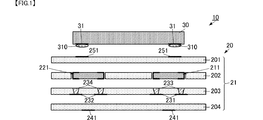
本発明の第1の実施形態に係る樹脂回路基板および部品搭載樹脂回路基板について、図を参照して説明する。図1は、本発明の第1の実施形態に係る部品搭載樹脂回路基板の構成を示す分解側面断面図である。図2は、本発明の第1の実施形態に係る部品搭載樹脂回路基板の構成を示す側面断面図である。図3は、本発明の第1の実施形態に係る部品搭載樹脂回路基板の部品配置の概念を示すための平面図である。 A resin circuit board and a component-mounted resin circuit board according to a first embodiment of the present invention will be described with reference to the drawings. FIG. 1 is an exploded side sectional view showing the configuration of a component-mounted resin circuit board according to the first embodiment of the present invention. FIG. 2 is a side sectional view showing the configuration of the component-mounted resin circuit board according to the first embodiment of the present invention. FIG. 3 is a plan view for illustrating the concept of component arrangement of the component-mounted resin circuit board according to the first embodiment of the present invention.
図1、図2に示すように、部品搭載樹脂回路基板10は、樹脂回路基板20と第1部品30とを備える。
As shown in FIGS. 1 and 2, the component-mounted resin circuit board 10 includes a
第1部品30は、例えば、高周波ICを形成した半導体チップ部品であり、主面の一方面に複数の端子導体31が形成されている。第1部品30は、平面視して矩形である。
The
複数の端子導体31は、一方面に配列形成されている。例えば、図3の例では、複数の端子導体31は、第1部品30を平面視して2×2の配列で形成されている。複数の端子導体31は、第1部品30の側面付近に配置されている。端子導体31には、金属バンプ310、例えば、半田バンプや金バンプ等が形成されている。
The plurality of
樹脂回路基板20は、積層体21、第2部品211,212,221,222を備える。積層体21は、複数の樹脂層201,202,203,204を積層してなる。複数の樹脂層201,202,203,204は、熱可塑性樹脂からなり、例えば、液晶ポリマを主材料としてなる。
The
積層体21の表面、すなわち、樹脂層201の表面には、複数の実装用ランド導体251が形成されている。複数の実装用ランド導体251は、矩形の導体パターンである。複数の実装用ランド導体251は、ここに実装される第1部品30の端子導体31と同じ配列パターンで形成されている。積層体21の裏面、すなわち、樹脂層204の裏面には、複数の外部接続導体241が形成されている。
A plurality of mounting
第2部品211,212,221,222は、樹脂層201,202,203,204よりも弾性率の高い材料からなる。例えば、第2部品211,212,221,222は、実装型コンデンサ等の受動回路素子からなる。第2部品211,212,221,222は、積層体21の内部に配置されている。具体的には、図1に示すように、示すように、積層体21の高さ方向における樹脂層202と同じ位置に配置されている。さらに、図3に示すように、樹脂回路基板20を平面視して、第2部品211,212,221,222は、複数の実装用ランド導体251と重なっている。
The
第2部品211,212,221,222は、樹脂層203に形成された層間接続導体231,232を介して、樹脂層203と樹脂層204との間に配置された導体パターン233,234にそれぞれ接続されている。
The
第1部品30は、このような構成の積層体21の表面に実装されている。この際、第1部品30の端子導体31は、実装用ランド導体251に対して、超音波接合されている。この端子導体31と実装用ランド導体251が超音波接合される界面が、本発明の「超音波接合部」に対応する。
The
ここで、第2部品211,212,221,222は、次の条件を満たす位置に配置されている。部品搭載樹脂回路基板10を平面視して、第2部品211,212,221,222の2つを組み合わせて、これらの配置位置の間を結ぶ直線が第1部品30の重心G30を通る。この際、全ての組み合せのうち、少なくとも1つの組み合わせによる直線が第1部品30の重心Gを通っていればよい。例えば、図3の例であれば、部品搭載樹脂回路基板10を平面視して、第2部品211の配置領域の所定点と第2部品222の配置領域の所定点とを結ぶ直線RL1は、第1部品30の重心G30を通る。また、部品搭載樹脂回路基板10を平面視して、第2部品221の配置領域の所定点と第2部品212の配置領域の所定点とを結ぶ直線RL2は、第1部品30の重心G30を通る。言い換えれば、第2部品211,212,221,222が重心Gに対して、特定の方位に寄っている配列でなければよい。
Here, the
なお、これは、樹脂回路基板20単体であれば、樹脂回路基板20を平面視して、第2部品211,212,221,222の2つを組み合わせて、これらの配置位置の間を結ぶ直線が複数の実装用ランド導体251の配置位置の幾何学的中心を通るという条件に置き換えることも可能である。
If this is a
このような構成とすることによって、積層体21よりも弾性率が高い第2部品211,212,221,222が、第1部品30を樹脂回路基板20に超音波接合する際の土台となり、接合時の実装用ランド導体251の部分の接合安定性を向上することができる。また、このような第2部品211,212,221,222の配置パターンとすることによって、超音波接合時に加わる超音波振動の偏りが抑制される。これにより、複数の実装用ランド導体251に安定した超音波振動が与えられる。したがって、第1部品30の端子導体31を樹脂回路基板20の実装用ランド導体251に確実に接合し、接合強度を安定化することができる。
By adopting such a configuration, the
さらに、第2部品211,212,221,222は、樹脂回路基板20の高さ方向の同じ位置にある。また、樹脂回路基板20の高さ方向における、樹脂回路基板20の表面からの第2部品211,212,221,222の距離DPは、樹脂回路基板20の高さDの半分以下である。このような構成とすることによって、第2部品211,212,221,222と実装用ランド導体251の間に配置される樹脂層の厚みを薄くできる。接合の際の樹脂層の変形は、樹脂層の厚みが薄いほど小さい。これにより、接合の際の樹脂層の変形の影響を抑制でき、接合強度をさらに安定化することができる。
Further, the
この際、図1に示すように、積層体21を構成する複数の樹脂層201,202,203,204における樹脂層202に第2部品211,212,221,222を配置することで、第2部品211,212,221,222と実装用ランド導体251の間に配置される樹脂層は、樹脂層201のみとなる。したがって、第2部品211,212,221,222と実装用ランド導体251の間に配置される樹脂層の厚みを、樹脂層201の厚み分だけにすることができる。接合の際の樹脂層の変形の影響を抑制でき、接合強度をさらに安定化することができる。
At this time, as shown in FIG. 1, the
また、図1、図2に示すように、第2部品211,212,221,222を積層体21内の導体パターン233,234に接続する層間接続導体231,232は、第2部品211,212,221,222における実装用ランド導体251と反対側の面に配置されている。これにより、第1部品30が樹脂回路基板20に接合される際の層間接続導体231,232の形状変化の影響を抑制できる。したがって、第1部品30を樹脂回路基板20に実装する際の端子導体31と実装用ランド導体251との接合強度をさらに安定化することができる。
As shown in FIGS. 1 and 2, the
なお、このような構成からなる部品搭載樹脂回路基板は、次に示す製造フローによって、製造される。 In addition, the component mounting resin circuit board which consists of such a structure is manufactured by the manufacturing flow shown next.
まず、複数の樹脂層201,202,203,204を用意する。樹脂層201,202,203,204には、例えば銅箔等の金属箔からなる所望の導体パターンが形成されている。例えば、樹脂層201の表面には、実装用ランド導体251が形成されている。また、樹脂層202には、第2部品211,212,221,222を収容する孔が設けられている。
First, a plurality of
次に、樹脂層201,202,203,204を積層し、加熱圧着する。この際、第2部品211,212,221,222は、樹脂層202の孔に収容された状態で、積層、加熱圧着が行われる。これにより、樹脂回路基板20が形成される。
Next, the resin layers 201, 202, 203, and 204 are laminated and thermocompression bonded. At this time, the
次に、第1部品30を樹脂回路基板20に実装する。具体的には、第1部品30の端子導体31を、樹脂回路基板20の実装用ランド導体251に当接させて、端子導体31を実装用ランド導体251に超音波接合する。これにより、部品搭載樹脂回路基板10が形成される。
Next, the
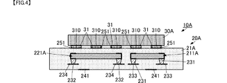
次に、本発明の第2の実施形態に係る樹脂回路基板および部品搭載樹脂回路基板について、図を参照して説明する。図4は、本発明の第2の実施形態に係る部品搭載樹脂回路基板の構成を示す側面断面図である。図5は、本発明の第2の実施形態に係る部品搭載樹脂回路基板の部品配置の概念を示すための平面図である。 Next, a resin circuit board and a component-mounted resin circuit board according to a second embodiment of the present invention will be described with reference to the drawings. FIG. 4 is a side sectional view showing the configuration of the component-mounted resin circuit board according to the second embodiment of the present invention. FIG. 5 is a plan view for illustrating the concept of component placement of the component-mounted resin circuit board according to the second embodiment of the present invention.
本実施形態に係る部品搭載樹脂回路基板10Aは、第1部品30Aの端子導体31の配置パターン、および、樹脂回路基板20Aの実装用ランド導体251の配置パターン、第2部品221A,221Aの配置パターンにおいて、第1の実施形態に係る部品搭載樹脂回路基板10と異なる。他の基本的な構成は、第1の実施形態に係る部品搭載樹脂回路基板10と同じである。
The component-mounted
図4、図5に示すように、複数の端子導体31は、第1部品30Aの主面の一方面の全面に亘って配列している。図5の例であれば、複数の端子導体31は、4×5の二次元配列によって配置されている。
As shown in FIGS. 4 and 5, the plurality of
樹脂回路基板20Aでは、複数の実装用ランド導体251は、複数の端子導体31に対応してそれぞれ積層体21Aの表面に配置されている。
In the
図5に示すように、第2部品211A,221Aは、部品搭載樹脂回路基板10Aを平面視して、第1部品30Aの対角に当たる位置に配置されている。例えば、図5の例では、第2部品211Aは、第1部品30Aの第1角付近の4個の端子導体31と重なるように配置されている。一方、第2部品221Aは、第1部品30Aの第2角(第1角の対角)付近の6個の端子導体31と重なるように配置されている。
As shown in FIG. 5, the
このような配置を用いることによって、部品搭載樹脂回路基板10Aを平面視して、第2部品211Aの配置領域の所定点と第2部品221Aの配置領域の所定点とを結ぶ直線RL1Aは、第1部品30Aの重心G30Aを通る。これにより、第1の実施形態に係る部品搭載樹脂回路基板10と同様の作用が得られ、端子導体31と実装用ランド導体251との接合強度を安定化することができる。
By using such an arrangement, the straight line RL1A connecting the predetermined point in the arrangement area of the
なお、上述の各実施形態では、第1部品の角に最も近い端子導体を含む態様を示したが、これに限るものではなく、少なくとも1組の第2部品の配置位置の所定位置を結ぶ直線が、第1部品の重心を通るようにすれば、本願発明の効果を得ることができる。 In each of the above-described embodiments, the aspect including the terminal conductor closest to the corner of the first component is shown. However, the present invention is not limited to this, and a straight line connecting the predetermined positions of the arrangement positions of at least one set of the second components. However, if the center of gravity of the first part is passed, the effect of the present invention can be obtained.
また、上述の各実施形態では、第1部品および第2部品の電気回路的な関係を示していないが、例えば、第1部品が高周波ICであり、第2部品がコンデンサであって、これらが電気回路として接続される態様であれば、コンデンサを高周波ICのノイズ除去用として用いることができ、高周波ICをノイズから保護することができる。この際、上述の実施形態に示すように、実装用ランド導体と第2部品とが近接しているので、コンデンサと高周波ICの距離が短くなる。したがって、これらの間の引き回し導体を短くでき、この引き回し導体によるノイズの影響を小さくでき、より有効である。 In each of the above-described embodiments, the electrical circuit relationship between the first component and the second component is not shown. For example, the first component is a high-frequency IC and the second component is a capacitor. As long as it is connected as an electric circuit, the capacitor can be used for noise removal of the high frequency IC, and the high frequency IC can be protected from noise. At this time, as shown in the above-described embodiment, since the mounting land conductor and the second component are close to each other, the distance between the capacitor and the high-frequency IC is shortened. Therefore, the routing conductor between them can be shortened, and the influence of noise by this routing conductor can be reduced, which is more effective.
また、本願発明とは異なり、上述の各実施形態において、1つの第2部品の面積を大きくし、全ての端子導体31(実装用ランド導体251)と重なるようにすることも考えられる。しかしながら、上述の実施形態に示すように、端子導体31(実装用ランド導体251)毎、または、全てではない所定数の端子導体31(実装用ランド導体251)に重なるように、複数の第2部品を配置することによって、積層体21内での配線自由度が向上する。例えば、第1部品と平面視で重なる領域であって、かつ、複数の第2部品の配置されていない領域においても配線(平面状の導体パターンや層間接続導体)を通すことができる。したがって、例えば、部品搭載樹脂回路基板を小型化することができる。
In addition, unlike the present invention, in each of the above-described embodiments, it is also conceivable to increase the area of one second component so as to overlap all the terminal conductors 31 (mounting land conductors 251). However, as shown in the above-described embodiment, the second conductors 31 (mounting land conductors 251) or a plurality of second conductors 31 (mounting land conductors 251) overlap each other or a predetermined number of terminal conductors 31 (mounting land conductors 251). By arranging the components, the degree of freedom of wiring in the stacked
なお、上述の説明では、第2部品の高さが樹脂層の1層分である態様をしましたが、複数層分であってもよい。この場合、第2部品を収容するキャビティは、複数層に亘って形成すればよい。 In the above description, the height of the second component is one layer of the resin layer, but may be a plurality of layers. In this case, the cavity for housing the second component may be formed over a plurality of layers.
また、図6に示すように、異方性導電膜を用いて端子導体と実装用ランド導体とを接合してもよい。図6は、本発明の他の接合態様を示す断面図である。 Further, as shown in FIG. 6, the terminal conductor and the mounting land conductor may be joined using an anisotropic conductive film. FIG. 6 is a cross-sectional view showing another bonding mode of the present invention.
図6に示す部品搭載樹脂回路基板10Bは、第1の実施形態に係る部品搭載樹脂回路基板10に対して、金属バンプ310が異方性導電膜320に変更された点で異なる。部品搭載樹脂回路基板10Dの他の構成は、部品搭載樹脂回路基板10と同様であり、同様の箇所の説明は省略する。
The component-mounted
図6に示すように、部品30の端子導体31と、樹脂回路基板20の実装用ランド導体251とは、異方性導電膜320によって接合されている。具体的な製造方法としては、端子導体31または実装用ランド導体251を覆うように異方性導電膜320を配置する。異方性導電膜320が端子導体31と実装用ランド導体251とに当接するように、部品30を樹脂回路基板20に配置する。この状態で、異方性導電膜320に対して加熱プレスを行うことによって、端子導体31と実装用ランド導体251との接合、すなわち、部品30と樹脂回路基板20との接合を実現する。
As shown in FIG. 6, the
このように、異方性導電膜を用いた態様であっても、上述の各実施形態の作用効果を実現できる。なお、異方性導電膜は、第2の実施形態にも適用できる。 Thus, even if it is an aspect using an anisotropic conductive film, the effect of each above-mentioned embodiment is realizable. The anisotropic conductive film can also be applied to the second embodiment.
また、上述の説明では、平面視して端子導体31が円形の場合を示しているが、端子導体31の形状はこれに限らず、矩形等であってもよい。
In the above description, the
10,10A,10B:部品搭載樹脂回路基板
20,20A:樹脂回路基板
21,21A:積層体
30,30A:第1部品
31:端子導体
201,202,203,204:樹脂層
211,212,221,222,211A,221A:第2部品
231,232:層間接続導体
231,232:導体パターン
241:外部接続導体
251:実装用ランド導体
310:金属バンプ
320:異方性導電膜10, 10A, 10B: Component-mounted
Claims (6)
前記積層体の表面に形成され、第1部品の端子導体が接合される複数の実装用ランド導体と、
前記積層体内に配置された、前記樹脂層よりも弾性率の高い複数の第2部品と、
を備え、
前記複数の第2部品は、前記複数の樹脂層のうちの一部の樹脂層に設けられた複数の孔にそれぞれ直接的に収容されており、
前記積層体を平面視して、前記複数の第2部品は、前記複数の第2部品を結ぶ直線が前記第1部品の重心を通り、且つ、前記複数の実装用ランド導体にそれぞれ重なるように、配置されており、
前記複数の第2部品は、層間接続導体によって、前記積層体の回路導体に接続されており、
前記第2部品に直接的に接続される前記層間接続導体は、前記第2部品に対して、前記実装用ランド導体側に形成されておらず、前記実装用ランド導体と反対側に形成されている、
樹脂回路基板。 A laminate formed by laminating a plurality of resin layers having thermoplasticity;
A plurality of mounting land conductors formed on the surface of the laminate, to which the terminal conductors of the first component are joined;
A plurality of second parts disposed in the laminate and having a higher elastic modulus than the resin layer;
With
The plurality of second parts are respectively directly accommodated in a plurality of holes provided in a part of the plurality of resin layers,
In plan view of the multilayer body, the plurality of second components are arranged such that straight lines connecting the plurality of second components pass through the center of gravity of the first component and overlap the plurality of mounting land conductors, respectively. Has been placed ,
The plurality of second parts are connected to the circuit conductor of the multilayer body by interlayer connection conductors,
The interlayer connection conductor directly connected to the second component is not formed on the mounting land conductor side with respect to the second component, and is formed on the side opposite to the mounting land conductor. Yes,
Resin circuit board.
請求項1に記載の樹脂回路基板。 The plurality of second parts are arranged at substantially the same position in the height direction of the laminate,
The resin circuit board according to claim 1.
請求項1または請求項2に記載の樹脂回路基板。 The plurality of second parts are arranged at positions closer to the front surface than the back surface of the laminate,
The resin circuit board according to claim 1 or 2 .
請求項1乃至請求項3のいずれかに記載の樹脂回路基板。 The plurality of second parts are arranged in the second resin layer from the surface side in the plurality of resin layers constituting the laminate,
The resin circuit board in any one of Claim 1 thru | or 3 .
前記積層体の表面に形成された複数の実装用ランド導体と、
端子導体が前記実装用ランド導体に実装された第1部品と、
前記積層体内に配置された、前記樹脂層よりも弾性率の高い複数の第2部品と、
を備え、
前記複数の第2部品は、前記複数の樹脂層のうちの一部の樹脂層に設けられた複数の孔にそれぞれ直接的に収容されており、
前記積層体を平面視して、前記複数の第2部品は、前記複数の第2部品を結ぶ直線が前記第1部品の重心を通り、且つ、前記複数の実装用ランド導体にそれぞれ重なるように、配置されており、
前記複数の第2部品は、層間接続導体によって、前記積層体の回路導体に接続されており、
前記第2部品に直接的に接続される前記層間接続導体は、前記第2部品に対して、前記実装用ランド導体側に形成されておらず、前記実装用ランド導体と反対側に形成されており、
前記端子導体は、超音波接合部、または、異方性導電部を介して、前記実装用ランド導体に接続されている、
部品搭載樹脂回路基板。 A laminate formed by laminating a plurality of resin layers having thermoplasticity;
A plurality of mounting land conductors formed on the surface of the laminate;
A first component pin conductor is mounted on the mounting land conductor,
A plurality of second parts disposed in the laminate and having a higher elastic modulus than the resin layer;
With
The plurality of second parts are respectively directly accommodated in a plurality of holes provided in a part of the plurality of resin layers,
In plan view of the multilayer body, the plurality of second components are arranged such that straight lines connecting the plurality of second components pass through the center of gravity of the first component and overlap the plurality of mounting land conductors, respectively. Has been placed,
The plurality of second parts are connected to the circuit conductor of the multilayer body by interlayer connection conductors,
The interlayer connection conductor directly connected to the second component is not formed on the mounting land conductor side with respect to the second component, and is formed on the side opposite to the mounting land conductor. And
The terminal conductor is connected to the mounting land conductor via an ultrasonic bonding part or an anisotropic conductive part,
Component-mounted resin circuit board.
前記第2部品は、前記第1部品に電気的に接続するコンデンサである、
請求項5に記載の部品搭載樹脂回路基板。 The first component is a high frequency IC;
The second component is a capacitor that is electrically connected to the first component.
The component-mounted resin circuit board according to claim 5 .
Applications Claiming Priority (3)
| Application Number | Priority Date | Filing Date | Title |
|---|---|---|---|
| JP2015172613 | 2015-09-02 | ||
| JP2015172613 | 2015-09-02 | ||
| PCT/JP2016/075265 WO2017038791A1 (en) | 2015-09-02 | 2016-08-30 | Resin circuit board and component-mounting resin circuit board |
Publications (2)
| Publication Number | Publication Date |
|---|---|
| JPWO2017038791A1 JPWO2017038791A1 (en) | 2018-03-01 |
| JP6477894B2 true JP6477894B2 (en) | 2019-03-06 |
Family
ID=58187473
Family Applications (1)
| Application Number | Title | Priority Date | Filing Date |
|---|---|---|---|
| JP2017538032A Active JP6477894B2 (en) | 2015-09-02 | 2016-08-30 | Resin circuit board, component-mounted resin circuit board |
Country Status (4)
| Country | Link |
|---|---|
| US (1) | US10278289B2 (en) |
| JP (1) | JP6477894B2 (en) |
| CN (1) | CN208016129U (en) |
| WO (1) | WO2017038791A1 (en) |
Family Cites Families (14)
| Publication number | Priority date | Publication date | Assignee | Title |
|---|---|---|---|---|
| JP4610067B2 (en) * | 2000-09-27 | 2011-01-12 | 京セラ株式会社 | Manufacturing method of wiring board with built-in electric element |
| US6512182B2 (en) * | 2001-03-12 | 2003-01-28 | Ngk Spark Plug Co., Ltd. | Wiring circuit board and method for producing same |
| JP3910387B2 (en) * | 2001-08-24 | 2007-04-25 | 新光電気工業株式会社 | Semiconductor package, manufacturing method thereof, and semiconductor device |
| JP4492233B2 (en) * | 2003-11-27 | 2010-06-30 | 株式会社デンソー | Semiconductor chip mounting structure and semiconductor chip mounting method |
| JP4489485B2 (en) * | 2004-03-31 | 2010-06-23 | 株式会社ルネサステクノロジ | Semiconductor device |
| JP3909772B2 (en) | 2004-10-19 | 2007-04-25 | 日本アビオニクス株式会社 | Semiconductor mounting method and flexible wiring board |
| JP2007027255A (en) * | 2005-07-13 | 2007-02-01 | Fujitsu Ltd | Semiconductor mounting substrate and its manufacturing method |
| JP5020671B2 (en) * | 2007-03-27 | 2012-09-05 | 日本特殊陶業株式会社 | Wiring board with built-in capacitor |
| EP2416355B1 (en) * | 2009-04-02 | 2016-12-21 | Murata Manufacturing Co., Ltd. | Circuit board |
| JPWO2011121993A1 (en) * | 2010-03-30 | 2013-07-04 | 株式会社村田製作所 | Parts assembly |
| CN103141164B (en) * | 2010-10-08 | 2016-06-08 | 株式会社村田制作所 | Substrate having built-in components and manufacture method thereof |
| WO2013187117A1 (en) * | 2012-06-14 | 2013-12-19 | 株式会社村田製作所 | High frequency module |
| WO2014148133A1 (en) * | 2013-03-19 | 2014-09-25 | 株式会社村田製作所 | Multilayer ceramic capacitor |
| KR102175723B1 (en) * | 2014-02-25 | 2020-11-09 | 삼성전자주식회사 | Semiconductor package |
-
2016
- 2016-08-30 CN CN201690001117.4U patent/CN208016129U/en active Active
- 2016-08-30 WO PCT/JP2016/075265 patent/WO2017038791A1/en active Application Filing
- 2016-08-30 JP JP2017538032A patent/JP6477894B2/en active Active
-
2018
- 2018-02-23 US US15/903,064 patent/US10278289B2/en active Active
Also Published As
| Publication number | Publication date |
|---|---|
| US20180182680A1 (en) | 2018-06-28 |
| WO2017038791A1 (en) | 2017-03-09 |
| US10278289B2 (en) | 2019-04-30 |
| CN208016129U (en) | 2018-10-26 |
| JPWO2017038791A1 (en) | 2018-03-01 |
Similar Documents
| Publication | Publication Date | Title |
|---|---|---|
| JP5660263B1 (en) | Electronic component, method for manufacturing electronic component, and circuit board | |
| JP3925615B2 (en) | Semiconductor module | |
| JP6809544B2 (en) | Electronics | |
| JP2006237276A (en) | Three-dimensional circuit device and its relay board | |
| JP6365794B2 (en) | Resin multilayer substrate and electronic device | |
| JP4046088B2 (en) | Three-dimensional electronic circuit device and its relay substrate and relay frame | |
| WO2008050521A1 (en) | 3d electronic circuit device | |
| JP6160308B2 (en) | Laminated board | |
| JP6233524B2 (en) | Component built-in board | |
| US9922918B2 (en) | Substrate for stacked module, stacked module, and method for manufacturing stacked module | |
| WO2017183394A1 (en) | Multilayer substrate and electronic device | |
| JP6593448B2 (en) | Resin substrate, component mounting resin substrate, and method of manufacturing component mounting resin substrate | |
| JP6593447B2 (en) | Resin substrate, component mounting resin substrate, resin substrate manufacturing method, component mounting resin substrate manufacturing method | |
| JP6323622B2 (en) | Component mounting board | |
| JP6477894B2 (en) | Resin circuit board, component-mounted resin circuit board | |
| JP6890575B2 (en) | Component mounting resin substrate | |
| JP2019040903A (en) | Circuit board and semiconductor module | |
| JP6089557B2 (en) | Electronic component module | |
| US10188000B2 (en) | Component mounting board | |
| JP6191808B1 (en) | Multilayer substrate and electronic equipment | |
| JP2007150181A (en) | Laminated packaged structure | |
| JP2017204490A (en) | Component mounting board, manufacturing method of component mounting board | |
| JP2012004154A (en) | Component embedding multi-layer wiring board and manufacturing method therefor | |
| JP2011187785A (en) | Electronic circuit module |
Legal Events
| Date | Code | Title | Description |
|---|---|---|---|
| A521 | Request for written amendment filed |
Free format text: JAPANESE INTERMEDIATE CODE: A523 Effective date: 20171115 |
|
| A621 | Written request for application examination |
Free format text: JAPANESE INTERMEDIATE CODE: A621 Effective date: 20171115 |
|
| A131 | Notification of reasons for refusal |
Free format text: JAPANESE INTERMEDIATE CODE: A131 Effective date: 20180925 |
|
| A521 | Request for written amendment filed |
Free format text: JAPANESE INTERMEDIATE CODE: A523 Effective date: 20181115 |
|
| TRDD | Decision of grant or rejection written | ||
| A01 | Written decision to grant a patent or to grant a registration (utility model) |
Free format text: JAPANESE INTERMEDIATE CODE: A01 Effective date: 20190108 |
|
| A61 | First payment of annual fees (during grant procedure) |
Free format text: JAPANESE INTERMEDIATE CODE: A61 Effective date: 20190121 |
|
| R150 | Certificate of patent or registration of utility model |
Ref document number: 6477894 Country of ref document: JP Free format text: JAPANESE INTERMEDIATE CODE: R150 |