JP6477147B2 - Method for measuring the amount of flux linkage in a permanent magnet motor, program for measuring the amount of flux linkage in a permanent magnet motor, and device for measuring the amount of flux linkage in a permanent magnet motor - Google Patents
Method for measuring the amount of flux linkage in a permanent magnet motor, program for measuring the amount of flux linkage in a permanent magnet motor, and device for measuring the amount of flux linkage in a permanent magnet motor Download PDFInfo
- Publication number
- JP6477147B2 JP6477147B2 JP2015070213A JP2015070213A JP6477147B2 JP 6477147 B2 JP6477147 B2 JP 6477147B2 JP 2015070213 A JP2015070213 A JP 2015070213A JP 2015070213 A JP2015070213 A JP 2015070213A JP 6477147 B2 JP6477147 B2 JP 6477147B2
- Authority
- JP
- Japan
- Prior art keywords
- permanent magnet
- induced voltage
- amount
- correction
- measuring
- Prior art date
- Legal status (The legal status is an assumption and is not a legal conclusion. Google has not performed a legal analysis and makes no representation as to the accuracy of the status listed.)
- Active
Links
Images


Description
本発明は、精度高く永久磁石電動機の鎖交磁束量を測定することができる永久磁石電動機の鎖交磁束量測定方法、永久磁石電動機の鎖交磁束量測定プログラム、および永久磁石電動機の鎖交磁束量測定装置に関する。 The present invention relates to a method for measuring the amount of magnetic flux linkage of a permanent magnet motor, a program for measuring the amount of magnetic flux linkage of a permanent magnet motor, and the magnetic flux linkage of a permanent magnet motor. The present invention relates to a quantity measuring device.
従来から、永久磁石同期電動機を制御する場合、d軸インダクタンス、q軸インダクタンス、巻線抵抗値、永久磁石電動機の鎖交磁束量などの電動機定数を用いて制御している。これらの電動機定数の測定精度の高さは、電動機制御の精度を左右する。このため、例えば、特許文献1には、d軸インダクタンス、q軸インダクタンスを測定する技術が記載されている。
Conventionally, when controlling a permanent magnet synchronous motor, control is performed using motor constants such as d-axis inductance, q-axis inductance, winding resistance value, and flux linkage of the permanent magnet motor. The high measurement accuracy of these motor constants affects the accuracy of motor control. For this reason, for example,
ところで、電動機定数のうち、永久磁石電動機の鎖交磁束量は、誘起電圧を回転子の回転速度で除算することによって得られる。したがって、鎖交磁束量を精度高く測定するためには、誘起電圧と回転子の回転速度とを精度高く測定する必要がある。 By the way, among the motor constants, the amount of flux linkage of the permanent magnet motor is obtained by dividing the induced voltage by the rotational speed of the rotor. Therefore, in order to measure the flux linkage with high accuracy, it is necessary to measure the induced voltage and the rotational speed of the rotor with high accuracy.
従来の相間誘起電圧の測定には、電動機に通電せずに、電動機の回転子を外部から回転させて、被測定電動機の端子電圧を観測する方法があるが、この方法では、回転子の回転軸を直接回転させる外力を供給するための装置が必要である。また、コンプレッサ用の電動機のように、回転子の回転軸が筐体外部に露出していない場合には、外力で回転子を回転させることができない。 In the conventional measurement of the interphase induced voltage, there is a method of observing the terminal voltage of the measured motor by rotating the rotor of the motor from the outside without energizing the motor. A device for supplying an external force that directly rotates the shaft is required. Further, when the rotating shaft of the rotor is not exposed to the outside of the housing as in a compressor motor, the rotor cannot be rotated by an external force.
なお、回転子の回転軸が筐体外部に露出していない場合、インバータで電動機を回転させたのち、フリーラン状態として回転させ、惰性での回転中に相間誘起電圧を観測すると、回転子が減速するので永久磁石電動機の鎖交磁束量を正確に測定することができない。 In addition, when the rotating shaft of the rotor is not exposed to the outside of the housing, after rotating the electric motor with an inverter, rotating it as a free-run state, and observing the interphase induced voltage during rotation in inertia, the rotor Since it decelerates, the amount of flux linkage of the permanent magnet motor cannot be measured accurately.
本発明は、上記に鑑みてなされたものであって、惰性による回転子の回転であっても、精度高く永久磁石電動機の鎖交磁束量を測定することができる永久磁石電動機の鎖交磁束量測定方法、永久磁石電動機の鎖交磁束量測定プログラム、および永久磁石電動機の鎖交磁束量測定装置を提供することを目的とする。 The present invention has been made in view of the above, and the amount of interlinkage magnetic flux of a permanent magnet motor that can accurately measure the amount of interlinkage magnetic flux of a permanent magnet motor even when the rotor rotates due to inertia. It is an object of the present invention to provide a measuring method, a flux linkage measuring program for a permanent magnet motor, and a flux linkage measuring device for a permanent magnet motor.
上述した課題を解決し、目的を達成するために、本発明にかかる永久磁石電動機の鎖交磁束量測定方法は、永久磁石電動機内の鎖交磁束量を測定する永久磁石電動機の鎖交磁束量測定方法であって、永久磁石回転子が回転している状態から前記永久磁石電動機への電力供給の停止によって前記永久磁石回転子をフリーラン状態に移行させる電力供給停止時点における永久磁石回転子の回転速度を取得するとともに該電力供給停止時点から電動機の誘起電圧を所定サンプリング周期で測定する誘起電圧測定ステップと、測定された誘起電圧の時間変化を指数関数的減衰であるとしてその減衰量を決定する減衰量決定ステップと、前記減衰量を有した減衰指数関数をもとに前記永久磁石回転子の前記回転速度の減速に対応する時系列のサンプリング時点を補正した補正サンプリング時点を求め、さらに該補正サンプリング時点における補正誘起電圧及び補正回転角度を算出する補正ステップと、前記補正誘起電圧の振幅値を算出する補正誘起電圧振幅値算出ステップと、前記補正誘起電圧の振幅値をフリーラン状態開始時の前記回転速度値で除算した値を前記永久磁石電動機の鎖交磁束量として算出する鎖交磁束量算出ステップと、を含むことを特徴とする。 In order to solve the above-described problems and achieve the object, a method for measuring the amount of flux linkage in a permanent magnet motor according to the present invention is the amount of flux linkage in a permanent magnet motor that measures the amount of flux linkage in a permanent magnet motor. A measuring method, wherein the permanent magnet rotor is shifted to a free-run state by stopping the power supply to the permanent magnet motor from a state where the permanent magnet rotor is rotating. An induced voltage measurement step for obtaining the rotation speed and measuring the induced voltage of the motor at a predetermined sampling period from the time when the power supply is stopped, and determining the amount of attenuation by assuming that the time change of the measured induced voltage is exponential decay And a time-series sampling corresponding to the reduction of the rotational speed of the permanent magnet rotor based on the attenuation exponent function having the attenuation amount. A correction step for obtaining a correction sampling time point for correcting the time point, further calculating a correction induced voltage and a correction rotation angle at the correction sampling time point, a correction induced voltage amplitude value calculation step for calculating an amplitude value of the correction induced voltage, A linkage magnetic flux amount calculating step of calculating a value obtained by dividing the amplitude value of the correction induced voltage by the rotation speed value at the start of the free-run state as the linkage magnetic flux amount of the permanent magnet motor.
また、本発明にかかる永久磁石電動機の鎖交磁束量測定方法は、上記の発明において、永久磁石電動機内の鎖交磁束量を測定する永久磁石電動機の鎖交磁束量測定方法であって、永久磁石回転子が回転している状態から前記永久磁石電動機への電力供給の停止によって前記永久磁石回転子をフリーラン状態に移行させる電力供給停止時点における前記永久磁石回転子の回転速度を取得するとともに該電力供給停止時点から電動機の誘起電圧を所定サンプリング周期で測定する誘起電圧測定ステップと、測定された誘起電圧の時間変化を指数関数的減衰であるとしてその減衰量を決定する指数部の減衰係数を変数とした減衰指数関数を乗算した三角関数に前記誘起電圧を乗算した相関処理によって求められた相関値が最大となるときの最適減衰係数を決定する最適減衰係数決定ステップと、前記最適減衰係数を有した最適減衰指数関数をもとに前記永久磁石回転子の回転速度の減速に対応する時系列のサンプリング時点を補正した補正サンプリング時点を求め、さらに該補正サンプリング時点における補正誘起電圧及び補正回転角度を算出する補正ステップと、前記補正回転角度を変数とする基本波三角関数に前記補正誘起電圧を乗算した相関処理によって求められた相関値をもとに基本波成分の補正誘起電圧振幅値を算出する補正誘起電圧振幅値算出ステップと、前記補正誘起電圧振幅値をフリーラン状態開始時の回転速度で除算した値を前記永久磁石電動機の鎖交磁束量として算出する鎖交磁束量算出ステップと、を含むことを特徴とする。 A method of measuring the amount of flux linkage of a permanent magnet motor according to the present invention is the method of measuring the amount of flux linkage of a permanent magnet motor that measures the amount of flux linkage in the permanent magnet motor in the above invention. While acquiring the rotational speed of the permanent magnet rotor at the time of stopping the power supply to shift the permanent magnet rotor to the free-run state by stopping the power supply to the permanent magnet motor from the state where the magnet rotor is rotating An induced voltage measurement step for measuring the induced voltage of the electric motor at a predetermined sampling period from the time when the power supply is stopped, and an attenuation coefficient of an exponent part for determining a time variation of the measured induced voltage as an exponential decay. Optimum attenuation when the correlation value obtained by the correlation processing obtained by multiplying the induced voltage by the trigonometric function obtained by multiplying the attenuation exponential function with the variable as the variable is the maximum An optimum damping coefficient determining step for determining the number, and a corrected sampling time point obtained by correcting a time-series sampling time corresponding to a reduction in the rotational speed of the permanent magnet rotor based on the optimum damping index function having the optimum damping coefficient And a correction step for calculating a correction induced voltage and a correction rotation angle at the time of the correction sampling, and a correlation obtained by a correlation process obtained by multiplying the fundamental wave trigonometric function having the correction rotation angle as a variable by the correction induction voltage. A corrected induced voltage amplitude value calculating step for calculating a corrected induced voltage amplitude value of a fundamental wave component based on the value; and a value obtained by dividing the corrected induced voltage amplitude value by a rotation speed at the start of a free-run state. An interlinkage magnetic flux amount calculating step for calculating the interlinkage magnetic flux amount.
また、本発明にかかる永久磁石電動機の鎖交磁束量測定方法は、上記の発明において、前記最適減衰係数決定ステップ及び前記補正誘起電圧振幅値算出ステップでは、正弦波を用いた相間値及び余弦波を用いた相間値に対する2乗和の平方根を用いることを特徴とする。 Further, the interlinkage magnetic flux amount measuring method for a permanent magnet motor according to the present invention is the above invention, wherein in the optimum damping coefficient determination step and the corrected induced voltage amplitude value calculation step, an interphase value and a cosine wave using a sine wave are used. The square root of the sum of squares for the interphase value using is used.
また、本発明にかかる永久磁石電動機の鎖交磁束量測定プログラムは、永久磁石電動機内の鎖交磁束量を測定する永久磁石電動機の鎖交磁束量測定プログラムであって、制御部に、永久磁石回転子が回転している状態から前記永久磁石電動機への電力供給の停止によって前記永久磁石回転子をフリーラン状態に移行させる電力供給停止時点における永久磁石回転子の回転速度を取得するとともに該電力供給停止時点から電動機の誘起電圧を所定サンプリング周期で測定する誘起電圧測定ステップと、測定された誘起電圧の時間変化を指数関数的減衰であるとしてその減衰量を決定する減衰量決定ステップと、前記減衰量を有した減衰指数関数をもとに前記永久磁石回転子の前記回転速度の減速に対応する時系列のサンプリング時点を補正した補正サンプリング時点を求め、さらに該補正サンプリング時点における補正誘起電圧及び補正回転角度を算出する補正ステップと、前記補正誘起電圧の振幅値を算出する補正誘起電圧振幅値算出ステップと、前記補正誘起電圧の振幅値をフリーラン状態開始時の前記回転速度値で除算した値を前記永久磁石電動機の鎖交磁束量として算出する鎖交磁束量算出ステップと、を実行させることを特徴とする。 A program for measuring the amount of flux linkage in a permanent magnet motor according to the present invention is a program for measuring the amount of flux linkage in a permanent magnet motor for measuring the amount of flux linkage in a permanent magnet motor. Obtaining the rotational speed of the permanent magnet rotor at the time of stopping the power supply for shifting the permanent magnet rotor to the free-run state by stopping the power supply to the permanent magnet motor from the state where the rotor is rotating An induced voltage measuring step for measuring the induced voltage of the electric motor at a predetermined sampling period from the time of supply stop, an attenuation amount determining step for determining the attenuation amount with the time change of the measured induced voltage as exponential decay, and Based on a damping index function having a damping amount, the time series sampling time points corresponding to the reduction of the rotational speed of the permanent magnet rotor were corrected. A correction step for obtaining a positive sampling time point, calculating a correction induced voltage and a correction rotation angle at the correction sampling time point, a correction induced voltage amplitude value calculating step for calculating an amplitude value of the correction induced voltage, and a correction induced voltage A linkage magnetic flux amount calculating step of calculating a value obtained by dividing the amplitude value by the rotation speed value at the start of the free-run state as the linkage magnetic flux amount of the permanent magnet motor is executed.
また、本発明にかかる永久磁石電動機の鎖交磁束量測定装置は、永久磁石電動機内の鎖交磁束量を測定する永久磁石電動機の鎖交磁束量測定装置であって、永久磁石回転子が回転している状態から前記永久磁石電動機への電力供給の停止によって前記永久磁石回転子をフリーラン状態に移行させる電力供給停止時点における永久磁石回転子の回転速度を取得するとともに該電力供給停止時点から電動機の誘起電圧を所定サンプリング周期で測定する誘起電圧測定部と、測定された誘起電圧の時間変化を指数関数的減衰であるとしてその減衰量を決定する減衰量決定部と、前記減衰量を有した減衰指数関数をもとに前記永久磁石回転子の前記回転速度の減速に対応する時系列のサンプリング時点を補正した補正サンプリング時点を求め、さらに該補正サンプリング時点における補正誘起電圧及び補正回転角度を算出する補正部と、前記補正誘起電圧の振幅値を算出する補正誘起電圧振幅値算出部と、前記補正誘起電圧の振幅値をフリーラン状態開始時の前記回転速度値で除算した値を前記永久磁石電動機の鎖交磁束量として算出する鎖交磁束量算出部と、を備えたことを特徴とする。 The apparatus for measuring the amount of flux linkage in a permanent magnet motor according to the present invention is a device for measuring the amount of flux linkage in a permanent magnet motor for measuring the amount of flux linkage in a permanent magnet motor, wherein the permanent magnet rotor rotates. The rotation speed of the permanent magnet rotor at the time of stopping the power supply for shifting the permanent magnet rotor to the free-run state by stopping the power supply to the permanent magnet motor from the state where the power supply is stopped and from the time of stopping the power supply An induced voltage measuring unit that measures the induced voltage of the motor at a predetermined sampling period; an attenuation determining unit that determines the amount of attenuation of the measured induced voltage over time as exponential attenuation; and the attenuation amount. A corrected sampling time point obtained by correcting a time-series sampling time point corresponding to the reduction of the rotation speed of the permanent magnet rotor based on the damping index function obtained; A correction unit that calculates a correction induced voltage and a correction rotation angle at the time of correction sampling, a correction induced voltage amplitude value calculation unit that calculates an amplitude value of the correction induced voltage, and an amplitude value of the correction induced voltage at the start of a free-run state A flux linkage amount calculation unit that calculates a value obtained by dividing the rotation speed value as a flux linkage amount of the permanent magnet motor.
本発明によれば、永久磁石回転子が回転している状態から永久磁石電動機への電力供給の停止によって前記永久磁石回転子をフリーラン状態に移行させる電力供給停止時点における永久磁石回転子の回転速度を取得するとともに該電力供給停止時点から電動機の誘起電圧を所定サンプリング周期で測定し、測定された誘起電圧の時間変化を指数関数的減衰であるとしてその減衰量を決定し、前記減衰量を有した減衰指数関数をもとに前記永久磁石回転子の前記回転速度の減速に対応する時系列のサンプリング時点を補正した補正サンプリング時点を求め、さらに該補正サンプリング時点における補正誘起電圧及び補正回転角度を算出し、前記補正誘起電圧の振幅値を算出し、前記補正誘起電圧の振幅値をフリーラン状態開始時の前記回転速度値で除算した値を前記永久磁石電動機の鎖交磁束量として算出するようにしている。これによって、回転子が惰性で回転し、摩擦や回転負荷による影響で減速していく場合であっても、精度高く永久磁石電動機の鎖交磁束量を測定することができる。 According to the present invention, the rotation of the permanent magnet rotor at the time of stopping the power supply in which the permanent magnet rotor is shifted to the free run state by stopping the power supply to the permanent magnet motor from the state in which the permanent magnet rotor is rotating. The speed is acquired and the induced voltage of the motor is measured at a predetermined sampling period from the time when the power supply is stopped, the time variation of the measured induced voltage is determined as exponential decay, and the amount of decay is determined. A correction sampling time point obtained by correcting a time series sampling time point corresponding to the deceleration of the rotation speed of the permanent magnet rotor is obtained based on the attenuation exponent function, and a correction induced voltage and a correction rotation angle at the correction sampling time point are obtained. Calculating the amplitude value of the corrected induced voltage, and calculating the amplitude value of the corrected induced voltage as the rotational speed at the start of a free-run state. In that the dividing value calculated as the flux linkage amount of the permanent magnet motor. Thereby, even when the rotor rotates due to inertia and decelerates due to the influence of friction or rotational load, the amount of magnetic flux linkage of the permanent magnet motor can be measured with high accuracy.
以下、添付図面を参照してこの発明を実施するための形態について説明する。 DESCRIPTION OF EMBODIMENTS Hereinafter, embodiments for carrying out the present invention will be described with reference to the accompanying drawings.
(全体構成)
図1は、本発明の実施の形態である永久磁石電動機の鎖交磁束量測定装置10(以下、鎖交磁束量測定装置10という)を含む構成を示すブロック図である。図1において、鎖交磁束量測定装置10は、電動機制御装置1によって駆動制御される永久磁石電動機MO(以下、電動機MOという)内の鎖交磁束量を測定する。
(overall structure)
FIG. 1 is a block diagram showing a configuration including an interlinkage magnetic flux amount measuring device 10 (hereinafter referred to as an interlinkage magnetic flux amount measuring device 10) of a permanent magnet motor according to an embodiment of the present invention. In FIG. 1, an interlinkage magnetic flux
(永久磁石電動機)
図2に示すように、永久磁石電動機MOは、U相、V相、W相の各相の巻線がそれぞれ巻回されたU相コイル31、V相コイル32、W相コイル33を有し、各相コイル31〜33の巻線に交流電圧が印加されることによって永久磁石回転子(以下、回転子という)30が回転する永久磁石同期電動機である。好ましくは、永久磁石埋め込み型電動機である。駆動部3は、電気角で120°ずつ位相がずれた交流電圧を各相コイル31〜33に供給して回転子30を駆動する。
(Permanent magnet motor)
As shown in FIG. 2, the permanent magnet motor MO has a U-phase coil 31, a V-phase coil 32, and a W-
(電動機制御装置)
図1に示すように、電動機制御装置1は、非干渉化制御部6を含む電圧指令生成部2、駆動部3、電流検出部4、及び位相/角速度検出部5を有する。電流検出部4は、少なくとも2相の電流の振幅を検出する。例えば、電流検出部4は、U相の電流iuの振幅を検出する電流センサ41と、V相の電流ivの振幅を検出する電流センサ42とを有する。
(Motor control device)
As shown in FIG. 1, the electric
位相/角速度検出部5は、電流iuと電流ivとからW相の電流iwを算出し、この電流iwと、検出された電流iu及び電流ivとから得られる固定座標系(UVW座標系)の電流ベクトル(iu,iv,iw)を回転座標系(dq座標系)の電流ベクトル(Id,Iq)に変換する。そして、位相/角速度検出部5は、電流Id、電流Iq、回転子30の電気角θe(rad)、機械角角速度ωm(rad/s)を電圧指令生成部2に出力する。なお、電気角θeは駆動部3に出力され、電気角角速度ωeは鎖交磁束量測定装置10に出力される。なお、機械角角速度ωmは電気角角速度ωeを電動機MOの極対数Pnで除算することによって得られ、この際に得られた電気角角速度ωeが鎖交磁束量測定装置10に出力される。位相/角速度検出部5は、鎖交磁束量測定装置10に電気角角速度ωeでなく機械角角速度ωmを出力するようにしてもよい。この場合、鎖交磁束量測定装置10は、入力された機械角角速度ωmに極対数Pnを乗算することによって電気角角速度ωeを得ることができる。なお、極対数Pnは、定数として予め図示しない記憶部に保持される。ちなみに、本実施の形態では永久磁石電動機MOの制御を、いわゆるベクトル制御で行うが、本発明はこれに限られない。すなわち、以下でも説明するように、回転子30を所定回転数で回転させた状態からフリーラン状態に移行することができれば、どのような制御を用いても良い。
The phase /
電圧指令生成部2は、上位の図示しない外部コントローラから、d軸電流指令値Ido*、及び機械角角速度指令ωm*を受け、入力された電流Id、電流Iq、電気角θe、機械角角速度ωm、及び機械角角速度指令ωm*に応じて、d軸電圧指令値Vd*及びq軸電圧指令値Vq*を生成し、駆動部3に出力する。なお、d軸電圧指令値Vd*及びq軸電圧指令値Vq*は、位相/角速度検出部5にも出力され、位相/角速度検出部5は、d軸電圧指令値Vd*及びq軸電圧指令値Vq*、及び、電流Id及び電流Iqをもとに、回転子30の実際の位置と算出した位置とのずれである軸誤差Δθを求め、この軸誤差Δθをもとに、上述した電気角角速度ωeを算出する。位相/角速度検出部5は、電気角角速度ωeを極対数Pnで除算した機械角角速度ωmを出力し、電気角角速度ωeを積分した電気角θeを出力する。
The
非干渉化制御部6は、d軸電圧指令値Vd*とq軸電圧指令値Vq*との干渉化を防ぐため、電気角角速度ωe、電流Id、電流Iqをもとに、d軸電圧指令値Vd*とq軸電圧指令値Vq*との各補正値を出力する。この非干渉化制御部6は、予め求められた電動機MOの電動機定数である、d軸インダクタンス、q軸インダクタンス、巻線抵抗値、電動機MOの鎖交磁束量などを用いて電動機MOの駆動電圧を補正する。上述した鎖交磁束量測定装置10は、電動機MOの鎖交磁束量を予め測定するための装置である。なお、鎖交磁束量の測定時には、非干渉化測定部6に適当な磁束値で代用して、電動機MOを駆動する。また、鎖交磁束測定装置10は、電動機MOの鎖交磁束量を測定するときのみに電動機制御装置1に接続されることが好ましい。
The
駆動部3は、電圧指令生成部2から入力されたd軸電圧指令値Vd*及びq軸電圧指令値Vq*、及び、位相/角速度検出部5から入力された電気角θeをもとに、3相のU相電圧指令値Vu*、V相電圧指令値Vv*、W相電圧指令値Vw*を生成する。駆動部3は、生成されたU相電圧指令値Vu*、V相電圧指令値Vv*、W相電圧指令値Vw*をもとに、外部から入力された外部直流電圧Vdcを3相の交流電圧であるU相電圧、V相電圧、W相電圧に変換し、電動機MOの各相コイル31〜33に供給する。
The drive unit 3 is based on the d-axis voltage command value Vd * and the q-axis voltage command value Vq * input from the voltage
(鎖交磁束量測定装置の構成)
図1に示すように、鎖交磁束量測定装置10には、電動機制御装置1から、電気角角速度ωe、電力供給の停止信号SGが入力され、電圧検出部20から、電圧検出センサ21によって検出されたU相電圧Vu、及び電圧検出センサ22によって検出されたV相電圧Vvが入力される。
(Configuration of flux linkage measuring device)
As shown in FIG. 1, the interlinkage magnetic flux
鎖交磁束量測定装置10は、制御部CT、入出力部16、及び記憶部17を有する。また、制御部CTは、誘起電圧測定部11、減衰量決定部12、補正部13、補正誘起電圧振幅値算出部14、及び鎖交磁束量算出部15を有する。
The flux
なお、U相コイル31、V相コイル32、W相コイル33の各相間(電動機端子間)の相間誘起電圧は、電動機MOの鎖交磁束量(各相のコイルと鎖交する磁束量)の時間変化であり、電動機MOの鎖交磁束量と回転子30の角速度との積である。したがって、式(1)に示すように、電動機MOの鎖交磁束量Ψeは、誘起電圧の振幅値Euvを電気角角速度ωeで除算した値として求めることができる。ここで、鎖交磁束量Ψeは、電気角角速度における鎖交磁束量である。
Ψe=Euv/ωe …(1)
ただし、電動機制御装置1による制御は、回転座標系(dq座標系)を用いた制御を行い、この回転座標系では、鎖交磁束量Ψeの実効値(Ψe/2^(1/2))である鎖交磁束実効量Ψreが用いられる。この鎖交磁束実効量Ψreは、相間波高値電圧Euvを相間電圧実効値Eruvとすることによって得られる。すなわち、鎖交磁束実効量Ψreは、式(2)によって得られる。
Ψre=Eruv/ωe …(2)
The interphase induced voltage between the phases of the U-phase coil 31, V-phase coil 32, and W-phase coil 33 (between the motor terminals) is the amount of interlinkage magnetic flux of the motor MO (the amount of magnetic flux interlinking with the coils of each phase). This is a time change, and is the product of the amount of flux linkage of the motor MO and the angular velocity of the
Ψe = Euv / ωe (1)
However, the control by the electric
Ψre = Eruv / ωe (2)
まず、誘起電圧測定部11は、電動機MO内の回転子30が一定回転数Nで回転している状態から電動機MOへの電力供給を停止して回転子30をフリーラン状態に移行させる電力供給停止信号SGの受信時点の電気角角速度ωeを取得するとともに、電力供給停止信号SGの受信時点から電動機端子(コイル31〜33)間の相間誘起電圧、例えばU相コイル31とV相コイル32との間の相間誘起電圧Vuvを所定サンプリング周期Tsで測定する。
First, the induced
フリーラン状態は、駆動部3から電流を電動機MO側に供給せずに電動機制御装置1側をハイインピーダンス状態にし、惰性で回転子30を回転させる状態である。したがって、回転子30は、フリーラン状態では、摩擦や負荷による影響で減速する。
The free-run state is a state in which the
また、相間誘起電圧Vuvは、電圧検出センサ21が検出したU相電圧Vuから電圧検出センサ22が検出したV相電圧Vvを減算することによって得られる。なお、相間誘起電圧Vuvに替えて、相間誘起電圧Vvw、Vwuであってもよい。
The interphase induced voltage Vuv is obtained by subtracting the V-phase voltage Vv detected by the
相間誘起電圧Vuvのサンプリングは、鎖交磁束量測定装置10に対してサンプリング数mと、測定したい周期数Cとを指示することによってサンプリング周期Tsを可変できる。このサンプリング周期Tsは、次式(3)によって得られる。
Ts=(Pn×C)/N×(1/m) …(3)
なお、実際の測定では、回転子30がフリーラン状態で回転子30が減速するため、指示した周期数Cより少ない周期のデータとなる。
In the sampling of the interphase induced voltage Vuv, the sampling cycle Ts can be varied by instructing the interlinkage magnetic
Ts = (Pn × C) / N × (1 / m) (3)
In actual measurement, since the
図3は、誘起電圧測定部11が測定した相間誘起電圧Vuvの時間波形を示す図である。図3の●で示すプロットは、サンプリング時点での相間誘起電圧Vuvであり、実線は、各プロットを直線補間した値である。サンプリング数は、全部でm個である。t(n)は、n番目のサンプリング時点を示している。図3に示すように、相間誘起電圧Vuvは、フリーラン状態になった時点t(0)から摩擦と負荷とによって減速し、波高値も減少している。
FIG. 3 is a diagram illustrating a time waveform of the interphase induced voltage Vuv measured by the induced
減衰量決定部12は、測定された相間誘起電圧Vuvの時間変化を指数関数的減衰であるとして、その減衰量を決める減衰係数αを変数とした減衰指数関数η(n)を乗算した三角関数に、相間誘起電圧Vuv(n)を乗算した相関処理によって求められた相関値が最大となるときの最適減衰係数αmaxを決定する。 The attenuation amount determination unit 12 assumes that the time change of the measured interphase induced voltage Vuv is exponential attenuation, and multiplies the attenuation exponent function η (n) with the attenuation coefficient α that determines the attenuation amount as a variable. The optimum attenuation coefficient αmax when the correlation value obtained by the correlation processing multiplied by the interphase induced voltage Vuv (n) is maximized is determined.
まず、減衰量決定部12は、減衰指数関数η(n)を、時間に対する正規化減衰関数とし、指数関数の減衰量を決める変数として指数部の減衰係数αを用いて次式(4)として定義する。
η(n)=exp{−α×t(n)} …(4)
なお、上述したように、nは、0〜m−1である。
First, the attenuation amount determination unit 12 uses the attenuation exponent function η (n) as a normalized attenuation function with respect to time, and uses the attenuation coefficient α of the exponent part as a variable for determining the attenuation amount of the exponent function as the following equation (4): Define.
η (n) = exp {−α × t (n)} (4)
As described above, n is 0 to m-1.
また、各サンプリング時点nにおける電気角角速度ωe(n)は、フリーラン状態開始時t(0)における電気角角速度ωe(0)に対して、減衰指数関数η(n)に対応して次式(5)に示すように減衰するものとして電気角角速度ωeη(n)を定義する。
ωeη(n)=η(n)×ωe(0) …(5)
Further, the electrical angular angular velocity ωe (n) at each sampling time point n corresponds to the attenuation exponent function η (n) with respect to the electrical angular angular velocity ωe (0) at the start t (0) of the free-run state. As shown in (5), the electrical angular angular velocity ωeη (n) is defined as one that attenuates.
ωeη (n) = η (n) × ωe (0) (5)
電気角角速度ωeη(n)にサンプリング間隔時間(t(n)−t(n−1))を乗算してサンプリング間隔時間(t(n)−t(n−1))における電気角差Δθ(n)は、次式(6)のようになる。また、各サンプリング時点t(n)における永久磁石回転子30の回転角度θ(n)は、次式(7)で表せる。ここで、回転角度θ(n)は電気角である。
Δθ(n)={t(n)−t(n−1)}×ωeη(n) …(6)
θ(n)=θ(n−1)+Δθ(n) …(7)
The electrical angular difference Δθ (at the sampling interval time (t (n) −t (n−1)) is obtained by multiplying the electrical angular angular velocity ωeη (n) by the sampling interval time (t (n) −t (n−1)). n) is expressed by the following equation (6). Further, the rotation angle θ (n) of the
Δθ (n) = {t (n) −t (n−1)} × ωeη (n) (6)
θ (n) = θ (n−1) + Δθ (n) (7)
そして次式(8)、(9)に示すように、式(7)の回転角度θ(n)を用いて、減衰指数関数η(n)が乗算された三角関数の正弦成分である正弦減衰関数Sη(n)と余弦成分である余弦減衰関数Cη(n)とを生成する。
Sη(n)=η(n)×sin{θ(n)} [0≦θ(n)≦2kπ]
Sη(n)=0 [θ(n)>2kπ] …(8)
Cη(n)=η(n)×cos{θ(n)} [0≦θ(n)≦2kπ]
Cη(n)=0 [θ(n)>2kπ] …(9)
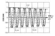
ただし、kは、電気角周期数であり、サンプリング数mを超えない周期数である。なお、図4は、減衰指数関数η(n)と、生成された正弦減衰関数Sη(n)及び余弦減衰関数Cη(n)との関係を示す図である。
Then, as shown in the following equations (8) and (9), a sine attenuation that is a sine component of a trigonometric function multiplied by the attenuation exponential function η (n) using the rotation angle θ (n) of the equation (7). A function Sη (n) and a cosine decay function Cη (n) which is a cosine component are generated.
Sη (n) = η (n) × sin {θ (n)} [0 ≦ θ (n) ≦ 2kπ]
Sη (n) = 0 [θ (n)> 2kπ] (8)
Cη (n) = η (n) × cos {θ (n)} [0 ≦ θ (n) ≦ 2kπ]
Cη (n) = 0 [θ (n)> 2kπ] (9)
However, k is the number of electrical angular cycles, and is the number of cycles not exceeding the sampling number m. FIG. 4 is a diagram showing the relationship between the attenuation exponent function η (n) and the generated sine attenuation function Sη (n) and cosine attenuation function Cη (n).
さらに、式(10)、(11)に示すように、計測された相関誘起電圧Vuv(n)と正弦減衰関数Sη(n)との相関処理、及び相関誘起電圧Vuvと余弦減衰関数Cη(n)との相関処理を行って、それぞれの相関値Esin,Ecosを求める。
![]()
![]()
![]()
![]()
ここで、一般に関数と関数とを乗算した相関処理の値は、2つの関数の類似度を示す。例えば、2つの関数の乗算値が大きければ、2つの関数は似ており、2つの関数の乗算値が小さければ、2つの関数は、あまり似ていないことになる。特に、2つの関数の乗算値が0の場合は、直交関係であり、無関係であると言える。 Here, in general, the value of the correlation processing obtained by multiplying the function by the function indicates the similarity between the two functions. For example, if the multiplication value of two functions is large, the two functions are similar, and if the multiplication value of the two functions is small, the two functions are not very similar. In particular, when the multiplication value of two functions is 0, it is an orthogonal relationship and can be said to be irrelevant.
そして、相間誘起電圧Vuv(n)と正弦減衰関数Sη(n)との相関値Esinと、相間誘起電圧Vuv(n)と余弦減衰関数Cη(n)との相関値Ecosとを用いた次式(12)、(13)によって、全体相関値Euvの大きさ|Euv|と位相φとがそれぞれ求められる。全体相関値Euvの大きさ|Euv|(振幅)及び位相φは、相間する三角関数の振幅|Euv|と位相φを意味する。全体相関値Euvの大きさ|Euv|は、相関値Esinと相関値Ecosとの2乗和の平方根の値である。
![]()

![]()
なお、式(10)、(11)における(1/kπ)は、フーリエ係数と同様に、相関値の一致度を調整するための係数である。式(10)、(11)の2式から得られる全体相関値Eruvの大きさ|Eruv|は、式(12)に示すように、相関値Esinと相関値Ecosとの2乗和の平方根の実効値(|Euv|/2^(1/2))として求められる。また、全体相関値Eruvの位相φは、式(13)に示すように、相関値Esinを相関値Ecosで除算した値のarctanとして求められる。 Note that (1 / kπ) in the equations (10) and (11) is a coefficient for adjusting the degree of coincidence of correlation values, similarly to the Fourier coefficient. The magnitude | Eruv | of the overall correlation value Eruv obtained from the two expressions (10) and (11) is the square root of the square sum of the correlation value Esin and the correlation value Ecos, as shown in the expression (12). It is obtained as an effective value (| Euv | / 2 ^ (1/2)). Further, the phase φ of the overall correlation value Eruv is obtained as arctan which is a value obtained by dividing the correlation value Esin by the correlation value Ecos as shown in the equation (13).
ところで、上述した減衰指数関数η(n)の減衰係数αは、変数である。そこで、変数の値を変化させて上述した全体相関値Eruvの大きさ|Eruv|の値の変化を求めると、図5に示すように変化し、全体相関値Eruvの大きさ|Eruv|が最大となる減衰係数αの最適値(最適減衰係数)αmaxを有する。図5では、最適減衰係数αmaxは、減衰係数αが2〜3の間に存在する。例えば、最適減衰係数αmaxは、2.5である。なお、減衰係数αが最大値近傍では、減衰係数αの値の変化が少ないので、ノイズによる誤検出を避けるため、減衰係数αを移動平均した値としている。減衰係数αが最適減衰係数αmaxのときの減衰指数関数η(n)は、相関誘起電圧Vuvの時間変化に最も相関するものであると言える。このようにして、減衰量決定部12は、最適減衰係数αmaxを決定する。 By the way, the attenuation coefficient α of the above-described attenuation index function η (n) is a variable. Therefore, when the value of the variable is changed to obtain the change in the value of the above-described overall correlation value Eruv | Eruv |, the change is as shown in FIG. 5 and the magnitude of the overall correlation value Eruv | The optimum value (optimum attenuation coefficient) αmax of the attenuation coefficient α is as follows. In FIG. 5, the optimum attenuation coefficient αmax exists between the attenuation coefficient α of 2 to 3. For example, the optimum attenuation coefficient αmax is 2.5. When the attenuation coefficient α is in the vicinity of the maximum value, there is little change in the value of the attenuation coefficient α. Therefore, in order to avoid erroneous detection due to noise, the attenuation coefficient α is a moving average value. It can be said that the attenuation index function η (n) when the attenuation coefficient α is the optimum attenuation coefficient αmax is most correlated with the time change of the correlation induced voltage Vuv. In this way, the attenuation amount determination unit 12 determines the optimum attenuation coefficient αmax.
次に、補正部13は、最適減衰係数αmaxを有した最適減衰指数関数ηα(n)を用いて、計測した相関誘起電圧Vuvを、フリーラン状態後の回転子30の減速がないものとした相関誘起電圧Vuvに戻すための逆変換を行うため、回転子30の電気角角速度ωeの減速に対応する時系列のサンプリング時点t(n)を、回転子30が減速しない状態に補正した補正サンプリング時点t´(n)を求め、さらに補正サンプリング時点t´(n)における補正相間誘起電圧Vuv´(n)及び補正回転角度θ´(n)を算出する。
Next, the correction unit 13 uses the optimum attenuation exponent function ηα (n) having the optimum attenuation coefficient αmax, and sets the measured correlation induced voltage Vuv so that there is no deceleration of the
補正サンプリング時点t´(n)は、次式(14)で表すことができる。
t´(n)=t´(n−1)+{t(n)−t(n−1)}×ηα(n)
…(14)
また、補正相間誘起電圧Vuv´(n)は、次式(15)で表すことができる。
Vuv´(n)=Vuv(n)/ηα(n) …(15)
さらに、補正サンプリング時点間隔時間(t´(n)−t´(n−1))における補正電気角差Δθ´(n)は、次式(16)で表すことができる。
Δθ´(n)=ωe×{(t´(n)−t´(n−1))} …(16)
また、補正サンプリング時刻t´(n)での補正回転角度θ´(n)は、次式(17)で表すことができる。
θ´(n)=ωe(0)×t´(n) …(17)
The corrected sampling time t ′ (n) can be expressed by the following equation (14).
t ′ (n) = t ′ (n−1) + {t (n) −t (n−1)} × ηα (n)
... (14)
Further, the corrected interphase induced voltage Vuv ′ (n) can be expressed by the following equation (15).
Vuv ′ (n) = Vuv (n) / ηα (n) (15)
Furthermore, the corrected electrical angle difference Δθ ′ (n) in the corrected sampling time interval (t ′ (n) −t ′ (n−1)) can be expressed by the following equation (16).
Δθ ′ (n) = ωe × {(t ′ (n) −t ′ (n−1))} (16)
Further, the corrected rotation angle θ ′ (n) at the corrected sampling time t ′ (n) can be expressed by the following equation (17).
θ ′ (n) = ωe (0) × t ′ (n) (17)
次に、補正誘起電圧振幅値算出部14は、補正回転角度θ´(n)を変数とする基本波三角関数に補正相間誘起電圧Vuv´(n)を乗算した相関処理によって求められた相関値をもとに補正相間誘起電圧実効値E´ruvを算出する。 Next, the corrected induced voltage amplitude value calculation unit 14 calculates the correlation value obtained by the correlation process in which the fundamental wave trigonometric function having the corrected rotation angle θ ′ (n) as a variable is multiplied by the corrected interphase induced voltage Vuv ′ (n). Based on the above, the corrected interphase induced voltage effective value E′ruv is calculated.
すなわち、補正誘起電圧振幅値算出部14は、まず、次式(18)、(19)に示すように、補正回転角度θ´(n)を用いて、補正サンプリング時点t´(n)での三角関数の基本波正弦成分である補正正弦波関数S(n)と基本波余弦成分である補正余弦波関数C(n)とを生成する。
S(n)=sin{θ´(n)} [0≦θ´(n)≦2kπ]
S(n)=0 [θ´(n)>2kπ] …(18)
C(n)=cos{θ´(n)} [0≦θ´(n)≦2kπ]
C(n)=0 [θ´(n)>2kπ] …(19)
ただし、kは、電気角周期数であり、サンプリング数mを超えない周期数である。
That is, first, the corrected induced voltage amplitude value calculation unit 14 uses the corrected rotation angle θ ′ (n) as shown in the following equations (18) and (19), at the corrected sampling time point t ′ (n). A corrected sine wave function S (n) that is a fundamental wave sine component of a trigonometric function and a corrected cosine wave function C (n) that is a fundamental wave cosine component are generated.
S (n) = sin {θ ′ (n)} [0 ≦ θ ′ (n) ≦ 2 kπ]
S (n) = 0 [θ ′ (n)> 2kπ] (18)
C (n) = cos {θ ′ (n)} [0 ≦ θ ′ (n) ≦ 2 kπ]
C (n) = 0 [θ ′ (n)> 2kπ] (19)
However, k is the number of electrical angular cycles, and is the number of cycles not exceeding the sampling number m.
さらに、式(20)、(21)に示すように、補正相関誘起電圧V´uvと補正正弦波関数S(n)との相関処理、及び補正相関誘起電圧V´uvと補正余弦波関数C(n)との相関処理を行って、それぞれの相関値E´sin,E´cosを求める。
![]()
![]()
![]()
![]()
そして、補正相関誘起電圧V´uvと補正正弦波関数S(n)との相関値E´sinと、補正相関誘起電圧V´uvと補正余弦波関数Cη(n)との相関値E´cosとを用いた次式(22)、(23)によって、全体相関値E´uvの大きさ|E´uv|と位相φ´とがそれぞれ求められる。
![]()
![]()
鎖交磁束量算出部15は、補正誘起電圧振幅値算出部14によって算出された補正相間誘起電圧実効値E´ruvをフリーラン状態開始時の電気角角速度ωe(0)で除算した値を電動機MOの鎖交磁束量として算出する。すなわち、式(1)の相関誘起電圧Eruvを補正相間誘起電圧実効値E´ruvとし、電気角角速度ωeを電気角角速度ωe(0)として、鎖交磁束実効量Ψreを求める。電動機制御装置1による制御は、相間誘起電圧の基本波成分の値と実効値とを用いて制御する場合が多く、上述した鎖交磁束実効量Ψreは、そのまま制御量として用いることができるので好適である。
The flux linkage calculating unit 15 divides the corrected interphase induced voltage effective value E′ruv calculated by the corrected induced voltage amplitude value calculating unit 14 by the electrical angular angular velocity ωe (0) at the start of the free-run state. Calculated as the amount of flux linkage of MO. That is, the interlinkage flux effective amount ψre is obtained by using the correlation induced voltage Eruv in the equation (1) as the corrected interphase induced voltage effective value E′ruv and the electrical angular angular velocity ωe as the electrical angular angular velocity ωe (0). The control by the
入出力部16は、タッチパネルなどによって実現される入出力インターフェースである。記憶部17は、メモリやハードディスクによって実現される。鎖交磁束量算出部15で求められた鎖交磁束実効量Ψreは、記憶部17に記憶される。また、鎖交磁束量算出部15で求められた鎖交磁束実効量Ψreは、入出力部16から出力される。入出力部16から出力され、あるいは記憶部17に記憶された鎖交磁束実効量Ψreは、その後、電動機制御装置1内に設定される。
The input /
(鎖交磁束量測定処理)
ここで、図7に示したフローチャートを参照して、鎖交磁束量測定装置10による鎖交磁束量測定処理手順について説明する。まず、誘起電圧測定部11は、電動機MO内の回転子30が一定回転数Nで回転している状態から電動機MOへの供給電力の停止によって回転子30をフリーラン状態に移行させる電力供給停止信号SGの受信時点の電気角角速度ωeを取得するとともに、電力供給停止信号SGの受信時点からU相コイル31とV相コイル32との間の相間誘起電圧Vuvを所定サンプリング周期Tsで測定する(ステップS101)。
(Interlinkage flux measurement process)
Here, with reference to the flowchart shown in FIG. 7, the interlinkage magnetic flux amount measurement processing procedure by the interlinkage magnetic flux
その後、減衰量決定部12は、測定された相間誘起電圧Vuvの時間変化を指数関数的減衰であるとして減衰係数αを変数とした減衰指数関数η(n)を乗算した三角関数に相間誘起電圧Vuv(n)を乗算した相関処理によって求められた相関値が最大となるときの最適減衰係数αmaxを決定する(ステップS102)。 After that, the attenuation amount determination unit 12 assumes that the time change of the measured interphase induced voltage Vuv is exponential decay and multiplies the trigonometric function obtained by multiplying the decay exponential function η (n) with the attenuation coefficient α as a variable. The optimum attenuation coefficient αmax when the correlation value obtained by the correlation process multiplied by Vuv (n) is maximized is determined (step S102).
補正部13は、最適減衰係数αmaxを有した最適減衰指数関数ηα(n)を用いて、計測した相関誘起電圧Vuvを、フリーラン状態後の回転子30の減速がないものとした相関誘起電圧Vuvに戻すための逆変換を行うため、回転子30の電気角角速度ωeの減速に対応する時系列のサンプリング時点t(n)を、回転子30が減速しない状態に補正した補正サンプリング時点t´(n)を求め、さらに補正サンプリング時点t´(n)における補正相間誘起電圧Vuv´(n)及び補正回転角度θ´(n)を算出する(ステップS103)。
The correction unit 13 uses the optimum attenuation exponent function ηα (n) having the optimum attenuation coefficient αmax to set the measured correlation induced voltage Vuv as a value that does not cause the
補正誘起電圧振幅値算出部14は、補正回転角度θ´(n)を変数とする基本波三角関数に補正相間誘起電圧Vuv´(n)を乗算した相関処理によって求められた相関値をもとに補正相間誘起電圧実効値E´ruvを算出する(ステップS104)。 The corrected induced voltage amplitude value calculation unit 14 is based on the correlation value obtained by the correlation process in which the fundamental wave trigonometric function having the corrected rotation angle θ ′ (n) as a variable is multiplied by the corrected interphase induced voltage Vuv ′ (n). The corrected interphase induced voltage effective value E′ruv is calculated (step S104).
鎖交磁束量算出部15は、補正誘起電圧振幅値算出部14によって算出された補正相間誘起電圧実効値E´ruvをフリーラン状態開始時の電気角角速度ωe(0)で除算した値を電動機MOの鎖交磁束量として算出し(ステップS105)、本処理を終了する。 The flux linkage calculating unit 15 divides the corrected interphase induced voltage effective value E′ruv calculated by the corrected induced voltage amplitude value calculating unit 14 by the electrical angular angular velocity ωe (0) at the start of the free-run state. Calculation is made as the amount of flux linkage of MO (step S105), and this processing is terminated.
なお、上述した鎖交磁束量測定処理手順は、鎖交磁束量測定装置10に実行させるプログラムとして、記憶部17に記憶され、制御部CTによって読み出されることによって実行される。そして、このプログラムは、インストール可能な形式または実行可能な形式のファイルデータでCD−ROM、フレキシブルディスク(FD)、CD−R、DVD(Digital Versatile Disk)、USB媒体、フラッシュメモリ等のコンピュータで読み取り可能な記録媒体に記録されて提供される。
The above-described interlinkage magnetic flux amount measurement processing procedure is stored in the
また、鎖交磁束量測定装置10に実行させるプログラムは、インターネット等のネットワークに接続されたコンピュータ上に格納し、ネットワーク経由でダウンロードさせることにより提供するように構成しても良い。さらに、鎖交磁束量測定装置10に実行させるプログラムをインターネット等のネットワーク経由で提供または配布するように構成しても良い。
The program to be executed by the flux
上述した実施の形態では、コンプレッサなどに設けられる電動機MOのように回転子30の回転軸が筐体外部に露出していない場合であっても、所定の処理手順や所定のプログラムによって、フリーラン状態の電動機MOの鎖交磁束量を自動的に測定することができる。したがって、測定者によって精度が左右されず、精度の高い測定が可能となる。特に、実際に測定される相間誘起電圧には高周波成分が含まれており、目視では、基本波成分の相間誘起電圧を精度高く測定することが困難である。
In the above-described embodiment, even if the rotating shaft of the
また、上述した実施の形態では、相間誘起電圧の減衰関数として1次関数ではなく、減衰指数関数を用いているので、測定結果を補正することで、精度の高い測定が可能となる。特に、指数関数は、時点が0のときの値が1であるため、関数の正規化が容易となる。 Further, in the above-described embodiment, the attenuation function of the interphase induced voltage is not a linear function but an attenuation exponent function, so that it is possible to perform highly accurate measurement by correcting the measurement result. In particular, since the exponential function has a value of 1 when the time is 0, normalization of the function is easy.
なお、上述した実施の形態で測定した鎖交磁束量の値は、外部の回転装置を用いて回転子30を回転させた場合と同程度の高い精度で得ることができた。
In addition, the value of the amount of flux linkage measured in the above-described embodiment could be obtained with the same high accuracy as when the
なお、上述した実施の形態では、相間誘起電圧を検出し、検出した相間誘起電圧から永久磁石電動機の鎖交磁束量を算出しているが、各相の誘起電圧を検出して、鎖交磁束量を算出してもよい。 In the above-described embodiment, the interphase induced voltage is detected, and the amount of interlinkage magnetic flux of the permanent magnet motor is calculated from the detected interphase induced voltage. However, the interlinkage magnetic flux is detected by detecting the induced voltage of each phase. The amount may be calculated.
また、上述した実施の形態では、誘起電圧測定部11が永久磁石電動機の鎖交磁束量測定装置10に設けられているが、本発明はこれに限られず、例えば電動機制御装置1に誘起電圧測定部11が設けられていてもよい。この場合には、例えば回転子30のフリーラン状態への移行時の電気角角速度ωeを電動機制御装置1で取得すると共に、フリーラン状態への移行時点から誘起電圧測定部11により電動機端子間の相関誘起電圧を測定して、前記電気角角速度ωeと誘起電圧とを電動機制御装置1に設けた記憶部で記憶しておくとよい。この構成の場合には、電動機制御装置1の記憶部で記憶したデータを永久磁石電動機の鎖交磁束量測定装置10と送受信すればよいため、角速度や誘起電圧をリアルタイムで送受信する必要がなくなる。また、電動機制御装置1と永久磁石電動機の鎖交磁束量測定装置10とが離れて設置されていても、データを送受信することで、鎖交磁束量の測定が可能となる。
In the above-described embodiment, the induced
1 電動機制御装置
2 電圧指令生成部
3 駆動部
4 電流検出部
5 位相/角速度検出部
6 非干渉化制御部
10 永久磁石電動機の鎖交磁束量測定装置
11 誘起電圧測定部
12 減衰量決定部
13 補正部
14 補正誘起電圧振幅値算出部
15 鎖交磁束量算出部
16 入出力部
17 記憶部
20 電圧検出部
21,22 電圧検出センサ
30 永久磁石回転子
31 U相コイル
32 V相コイル
33 W相コイル
41,42 電流センサ
CT 制御部
MO 永久磁石電動機
SG 電力供給停止信号
Vdc 外部直流電圧
αmax 最適減衰係数
ωm 機械角角速度
ωm* 機械角角速度指令
ωe 電気角角速度
θe 回転角度
Id,Iq,iu,iv 電流
Vd* d軸電圧指令値
Vq* q軸電圧指令値
Vu U相電圧
Vv V相電圧
DESCRIPTION OF
Claims (5)
永久磁石回転子が回転している状態から前記永久磁石電動機への電力供給の停止によって前記永久磁石回転子をフリーラン状態に移行させる電力供給停止時点における永久磁石回転子の回転速度を取得するとともに該電力供給停止時点から電動機の誘起電圧を所定サンプリング周期で測定する誘起電圧測定ステップと、
測定された誘起電圧の時間変化を指数関数的減衰であるとしてその減衰量を決定する減衰量決定ステップと、
前記減衰量を有した減衰指数関数をもとに前記永久磁石回転子の前記回転速度の減速に対応する時系列のサンプリング時点を補正した補正サンプリング時点を求め、さらに該補正サンプリング時点における補正誘起電圧及び補正回転角度を算出する補正ステップと、
前記補正誘起電圧の振幅値を算出する補正誘起電圧振幅値算出ステップと、
前記補正誘起電圧の振幅値をフリーラン状態開始時の前記回転速度値で除算した値を前記永久磁石電動機の鎖交磁束量として算出する鎖交磁束量算出ステップと、
を含むことを特徴とする永久磁石電動機の鎖交磁束量測定方法。 A method for measuring the amount of flux linkage in a permanent magnet motor for measuring the amount of flux linkage in a permanent magnet motor,
While acquiring the rotational speed of the permanent magnet rotor at the time of stopping the power supply for shifting the permanent magnet rotor to the free-run state by stopping the power supply to the permanent magnet motor from the state where the permanent magnet rotor is rotating An induced voltage measurement step of measuring the induced voltage of the electric motor at a predetermined sampling period from the time of stopping the power supply;
An attenuation determination step for determining the attenuation of the measured induced voltage over time as an exponential attenuation; and
A correction sampling time point obtained by correcting a time-series sampling time point corresponding to the reduction of the rotation speed of the permanent magnet rotor based on the attenuation index function having the attenuation amount is obtained, and a corrected induced voltage at the correction sampling time point And a correction step for calculating a correction rotation angle;
A corrected induced voltage amplitude value calculating step for calculating an amplitude value of the corrected induced voltage;
A linkage flux amount calculating step of calculating a value obtained by dividing the amplitude value of the correction induced voltage by the rotation speed value at the start of a free-run state as the linkage flux amount of the permanent magnet motor;
A method for measuring the amount of magnetic flux linkage of a permanent magnet motor.
永久磁石回転子が回転している状態から前記永久磁石電動機への電力供給の停止によって前記永久磁石回転子をフリーラン状態に移行させる電力供給停止時点における前記永久磁石回転子の回転速度を取得するとともに該電力供給停止時点から電動機の誘起電圧を所定サンプリング周期で測定する誘起電圧測定ステップと、
測定された誘起電圧の時間変化を指数関数的減衰であるとしてその減衰量を決定する指数部の減衰係数を変数とした減衰指数関数を乗算した三角関数に前記誘起電圧を乗算した相関処理によって求められた相関値が最大となるときの最適減衰係数を決定する最適減衰係数決定ステップと、
前記最適減衰係数を有した最適減衰指数関数をもとに前記永久磁石回転子の回転速度の減速に対応する時系列のサンプリング時点を補正した補正サンプリング時点を求め、さらに該補正サンプリング時点における補正誘起電圧及び補正回転角度を算出する補正ステップと、
前記補正回転角度を変数とする基本波三角関数に前記補正誘起電圧を乗算した相関処理によって求められた相関値をもとに基本波成分の補正誘起電圧振幅値を算出する補正誘起電圧振幅値算出ステップと、
前記補正誘起電圧振幅値をフリーラン状態開始時の回転速度で除算した値を前記永久磁石電動機の鎖交磁束量として算出する鎖交磁束量算出ステップと、
を含むことを特徴とする永久磁石電動機の鎖交磁束量測定方法。 A method for measuring the amount of flux linkage in a permanent magnet motor for measuring the amount of flux linkage in a permanent magnet motor,
Obtaining the rotational speed of the permanent magnet rotor at the time of stopping the power supply for shifting the permanent magnet rotor to a free-run state by stopping the power supply to the permanent magnet motor from the state where the permanent magnet rotor is rotating And an induced voltage measurement step for measuring the induced voltage of the electric motor at a predetermined sampling period from the time when the power supply is stopped,
The time variation of the measured induced voltage is assumed to be exponential decay, and is determined by a correlation process in which the induced voltage is multiplied by a trigonometric function obtained by multiplying the decay exponential function with the exponential decay coefficient as a variable that determines the amount of decay. An optimum attenuation coefficient determining step for determining an optimum attenuation coefficient when the obtained correlation value is maximized;
A correction sampling time point obtained by correcting a time-series sampling time point corresponding to a reduction in the rotational speed of the permanent magnet rotor is obtained based on the optimum damping index function having the optimum damping coefficient, and further, a correction induction at the correction sampling time point is obtained. A correction step for calculating a voltage and a correction rotation angle;
Correction induced voltage amplitude value calculation for calculating a corrected induced voltage amplitude value of the fundamental wave component based on a correlation value obtained by a correlation process obtained by multiplying the correction wave induced voltage by a fundamental wave trigonometric function having the correction rotation angle as a variable Steps,
A linkage magnetic flux amount calculating step of calculating a value obtained by dividing the correction induced voltage amplitude value by the rotation speed at the start of a free-run state as the flux linkage amount of the permanent magnet motor;
A method for measuring the amount of magnetic flux linkage of a permanent magnet motor.
制御部に、
永久磁石回転子が回転している状態から前記永久磁石電動機への電力供給の停止によって前記永久磁石回転子をフリーラン状態に移行させる電力供給停止時点における永久磁石回転子の回転速度を取得するとともに該電力供給停止時点から電動機の誘起電圧を所定サンプリング周期で測定する誘起電圧測定ステップと、
測定された誘起電圧の時間変化を指数関数的減衰であるとしてその減衰量を決定する減衰量決定ステップと、
前記減衰量を有した減衰指数関数をもとに前記永久磁石回転子の前記回転速度の減速に対応する時系列のサンプリング時点を補正した補正サンプリング時点を求め、さらに該補正サンプリング時点における補正誘起電圧及び補正回転角度を算出する補正ステップと、
前記補正誘起電圧の振幅値を算出する補正誘起電圧振幅値算出ステップと、
前記補正誘起電圧の振幅値をフリーラン状態開始時の前記回転速度値で除算した値を前記永久磁石電動機の鎖交磁束量として算出する鎖交磁束量算出ステップと、
を実行させることを特徴とする永久磁石電動機の鎖交磁束量測定プログラム。 A program for measuring the amount of flux linkage in a permanent magnet motor that measures the amount of flux linkage in a permanent magnet motor,
In the control unit,
While acquiring the rotational speed of the permanent magnet rotor at the time of stopping the power supply for shifting the permanent magnet rotor to the free-run state by stopping the power supply to the permanent magnet motor from the state where the permanent magnet rotor is rotating An induced voltage measurement step of measuring the induced voltage of the electric motor at a predetermined sampling period from the time of stopping the power supply;
An attenuation determination step for determining the attenuation of the measured induced voltage over time as an exponential attenuation; and
A correction sampling time point obtained by correcting a time-series sampling time point corresponding to the reduction of the rotation speed of the permanent magnet rotor based on the attenuation index function having the attenuation amount is obtained, and a corrected induced voltage at the correction sampling time point And a correction step for calculating a correction rotation angle;
A corrected induced voltage amplitude value calculating step for calculating an amplitude value of the corrected induced voltage;
A linkage flux amount calculating step of calculating a value obtained by dividing the amplitude value of the correction induced voltage by the rotation speed value at the start of a free-run state as the linkage flux amount of the permanent magnet motor;
A program for measuring the amount of flux linkage in a permanent magnet motor, characterized in that
永久磁石回転子が回転している状態から前記永久磁石電動機への電力供給の停止によって前記永久磁石回転子をフリーラン状態に移行させる電力供給停止時点における永久磁石回転子の回転速度を取得するとともに該電力供給停止時点から電動機の誘起電圧を所定サンプリング周期で測定する誘起電圧測定部と、
測定された誘起電圧の時間変化を指数関数的減衰であるとしてその減衰量を決定する減衰量決定部と、
前記減衰量を有した減衰指数関数をもとに前記永久磁石回転子の前記回転速度の減速に対応する時系列のサンプリング時点を補正した補正サンプリング時点を求め、さらに該補正サンプリング時点における補正誘起電圧及び補正回転角度を算出する補正部と、
前記補正誘起電圧の振幅値を算出する補正誘起電圧振幅値算出部と、
前記補正誘起電圧の振幅値をフリーラン状態開始時の前記回転速度値で除算した値を前記永久磁石電動機の鎖交磁束量として算出する鎖交磁束量算出部と、
を備えたことを特徴とする永久磁石電動機の鎖交磁束量測定装置。 An apparatus for measuring the amount of flux linkage in a permanent magnet motor for measuring the amount of flux linkage in a permanent magnet motor,
While acquiring the rotational speed of the permanent magnet rotor at the time of stopping the power supply for shifting the permanent magnet rotor to the free-run state by stopping the power supply to the permanent magnet motor from the state where the permanent magnet rotor is rotating An induced voltage measuring unit that measures the induced voltage of the electric motor at a predetermined sampling period from the time when the power supply is stopped;
An attenuation amount determination unit that determines the amount of attenuation as the exponential attenuation of the time change of the measured induced voltage;
A correction sampling time point obtained by correcting a time-series sampling time point corresponding to the reduction of the rotation speed of the permanent magnet rotor based on the attenuation index function having the attenuation amount is obtained, and a corrected induced voltage at the correction sampling time point And a correction unit for calculating a correction rotation angle;
A corrected induced voltage amplitude value calculating unit for calculating an amplitude value of the corrected induced voltage;
An interlinkage magnetic flux amount calculation unit for calculating a value obtained by dividing the amplitude value of the correction induced voltage by the rotation speed value at the start of a free-run state as an interlinkage magnetic flux amount of the permanent magnet motor;
A flux linkage measuring device for a permanent magnet electric motor, comprising:
Priority Applications (1)
| Application Number | Priority Date | Filing Date | Title |
|---|---|---|---|
| JP2015070213A JP6477147B2 (en) | 2015-03-30 | 2015-03-30 | Method for measuring the amount of flux linkage in a permanent magnet motor, program for measuring the amount of flux linkage in a permanent magnet motor, and device for measuring the amount of flux linkage in a permanent magnet motor |
Applications Claiming Priority (1)
| Application Number | Priority Date | Filing Date | Title |
|---|---|---|---|
| JP2015070213A JP6477147B2 (en) | 2015-03-30 | 2015-03-30 | Method for measuring the amount of flux linkage in a permanent magnet motor, program for measuring the amount of flux linkage in a permanent magnet motor, and device for measuring the amount of flux linkage in a permanent magnet motor |
Publications (2)
| Publication Number | Publication Date |
|---|---|
| JP2016192830A JP2016192830A (en) | 2016-11-10 |
| JP6477147B2 true JP6477147B2 (en) | 2019-03-06 |
Family
ID=57246917
Family Applications (1)
| Application Number | Title | Priority Date | Filing Date |
|---|---|---|---|
| JP2015070213A Active JP6477147B2 (en) | 2015-03-30 | 2015-03-30 | Method for measuring the amount of flux linkage in a permanent magnet motor, program for measuring the amount of flux linkage in a permanent magnet motor, and device for measuring the amount of flux linkage in a permanent magnet motor |
Country Status (1)
| Country | Link |
|---|---|
| JP (1) | JP6477147B2 (en) |
Cited By (1)
| Publication number | Priority date | Publication date | Assignee | Title |
|---|---|---|---|---|
| CN110470985A (en) * | 2019-07-16 | 2019-11-19 | 上海鲍麦克斯电子科技有限公司 | A kind of system and method detecting servo motor timing |
Families Citing this family (2)
| Publication number | Priority date | Publication date | Assignee | Title |
|---|---|---|---|---|
| JP7205306B2 (en) * | 2019-03-01 | 2023-01-17 | 株式会社Ihi | Rotating machine system and magnetic flux linkage estimation method |
| CN111880061B (en) * | 2020-08-03 | 2022-08-09 | 国网重庆市电力公司电力科学研究院 | Pulse wave velocity correction method for monitoring partial discharge of high-voltage cable |
Family Cites Families (4)
| Publication number | Priority date | Publication date | Assignee | Title |
|---|---|---|---|---|
| JPS61266087A (en) * | 1985-05-20 | 1986-11-25 | Meidensha Electric Mfg Co Ltd | Pickup device of motor |
| JPS62141993A (en) * | 1985-12-13 | 1987-06-25 | Hitachi Ltd | Driving method for brushless motor |
| US7188466B2 (en) * | 2004-02-10 | 2007-03-13 | General Electric Company | Passive, high-temperature amplifier for amplifying spark signals detected in igniter in gas turbine engine |
| CN104081652B (en) * | 2012-01-20 | 2016-06-29 | 三菱电机株式会社 | The control device of motor with permanent magnet and control method |
-
2015
- 2015-03-30 JP JP2015070213A patent/JP6477147B2/en active Active
Cited By (1)
| Publication number | Priority date | Publication date | Assignee | Title |
|---|---|---|---|---|
| CN110470985A (en) * | 2019-07-16 | 2019-11-19 | 上海鲍麦克斯电子科技有限公司 | A kind of system and method detecting servo motor timing |
Also Published As
| Publication number | Publication date |
|---|---|
| JP2016192830A (en) | 2016-11-10 |
Similar Documents
| Publication | Publication Date | Title |
|---|---|---|
| US9825579B2 (en) | Temperature estimating apparatus for synchronous motor | |
| EP3040690B1 (en) | Angle error correction device and angle error correction method for position detector | |
| KR101961106B1 (en) | Sensorless control method and apparatus thereof | |
| JP4519864B2 (en) | AC rotating machine electrical constant measuring method and AC rotating machine control apparatus used for carrying out this measuring method | |
| JP4578700B2 (en) | Brushless DC motor control device | |
| US8723462B2 (en) | Methods, systems and apparatus for estimating angular position and/or angular velocity of a rotor of an electric machine | |
| TWI525981B (en) | System, method and apparatus of sensor-less field oriented control for permanent magnet motor | |
| WO2017110855A1 (en) | Motor diagnostic method and electric power conversion equipment using same | |
| US11463033B2 (en) | Apparatus, system, and method for controlling motor | |
| JP5753474B2 (en) | Synchronous motor controller | |
| JP6477147B2 (en) | Method for measuring the amount of flux linkage in a permanent magnet motor, program for measuring the amount of flux linkage in a permanent magnet motor, and device for measuring the amount of flux linkage in a permanent magnet motor | |
| JP5909658B2 (en) | Motor constant calculation method and motor constant calculation apparatus for permanent magnet type synchronous motor | |
| EP3133732B1 (en) | Power conversion device and power conversion method | |
| JP2010035352A (en) | Device for estimating rotor position of synchronous electric motor | |
| JP4735439B2 (en) | Initial magnetic pole position estimation device for permanent magnet type synchronous motor | |
| JP7304891B2 (en) | Rotating machine control device and electric vehicle control device | |
| JP2019033582A (en) | Control device and control method | |
| JP2010035351A (en) | Device for estimating rotor position of synchronous electric motor | |
| KR102439814B1 (en) | Motor Speed Estimation Apparatus and Motor Speed Estimation Method | |
| KR101654826B1 (en) | System and method for driving multi-core architecture based AC motor position sensorless | |
| JP2009027799A (en) | Cylindrical synchronous motor system, method for detecting magnetic pole position of cylindrical synchronous motor, and driving method thereof | |
| JP6108114B2 (en) | Control device for permanent magnet type synchronous motor | |
| CN110086394B (en) | Control device | |
| JP5148789B2 (en) | Identification method of flux linkage and electrical time constant of permanent magnet synchronous motor | |
| JP6537461B2 (en) | Controller of rotating machine |
Legal Events
| Date | Code | Title | Description |
|---|---|---|---|
| A621 | Written request for application examination |
Free format text: JAPANESE INTERMEDIATE CODE: A621 Effective date: 20180307 |
|
| TRDD | Decision of grant or rejection written | ||
| A977 | Report on retrieval |
Free format text: JAPANESE INTERMEDIATE CODE: A971007 Effective date: 20181227 |
|
| A01 | Written decision to grant a patent or to grant a registration (utility model) |
Free format text: JAPANESE INTERMEDIATE CODE: A01 Effective date: 20190108 |
|
| A61 | First payment of annual fees (during grant procedure) |
Free format text: JAPANESE INTERMEDIATE CODE: A61 Effective date: 20190121 |
|
| R151 | Written notification of patent or utility model registration |
Ref document number: 6477147 Country of ref document: JP Free format text: JAPANESE INTERMEDIATE CODE: R151 |