JP6476868B2 - Picking system - Google Patents
Picking system Download PDFInfo
- Publication number
- JP6476868B2 JP6476868B2 JP2015000460A JP2015000460A JP6476868B2 JP 6476868 B2 JP6476868 B2 JP 6476868B2 JP 2015000460 A JP2015000460 A JP 2015000460A JP 2015000460 A JP2015000460 A JP 2015000460A JP 6476868 B2 JP6476868 B2 JP 6476868B2
- Authority
- JP
- Japan
- Prior art keywords
- storage shelf
- transfer device
- container
- picking system
- transfer
- Prior art date
- Legal status (The legal status is an assumption and is not a legal conclusion. Google has not performed a legal analysis and makes no representation as to the accuracy of the status listed.)
- Expired - Fee Related
Links
- 230000032258 transport Effects 0.000 claims description 22
- 239000000725 suspension Substances 0.000 description 3
- 239000000470 constituent Substances 0.000 description 2
- 230000000694 effects Effects 0.000 description 2
- 238000000034 method Methods 0.000 description 2
- 238000012986 modification Methods 0.000 description 2
- 230000004048 modification Effects 0.000 description 2
- 230000007547 defect Effects 0.000 description 1
- 238000010586 diagram Methods 0.000 description 1
- 238000002955 isolation Methods 0.000 description 1
Images
Landscapes
- Warehouses Or Storage Devices (AREA)
Description
本願発明は、保管された複数の容器内にそれぞれ収容される物品を作業者が選択的に取り出すピッキングシステムであって、前記容器が自動的に搬送されるピッキングシステムに関する。 The present invention relates to a picking system in which an operator selectively takes out articles respectively stored in a plurality of stored containers, and relates to a picking system in which the containers are automatically conveyed.
同種類の物品が収容されている容器であって、複数種類の物品に対応した複数の容器が保管されている保管棚から、作業者が伝票などに記された所定の物品を所定の個数取り出すピッキング作業が、物流の拠点などにおいて実施されている。 An operator takes out a predetermined number of predetermined articles on a slip or the like from a storage shelf in which a plurality of containers corresponding to a plurality of types of articles are stored. Picking work is carried out at logistics bases.
このピッキング作業としては、作業者が保管棚に沿って移動しながら、所定の物品を取り出す方式もあるが、昨今では作業者の負担を軽減し作業効率を向上させるため、容器を作業者の近傍まで自動で搬送するピッキング用自動倉庫が提案されている(例えば特許文献1参照)。 As this picking work, there is a method of taking out a predetermined article while the worker moves along the storage shelf, but recently, in order to reduce the burden on the worker and improve the work efficiency, the container is placed in the vicinity of the worker. There has been proposed an automatic warehouse for picking that automatically conveys the film (see Patent Document 1, for example).
例えば従来のピッキング用自動倉庫において、保管棚の一方の側方に容器を自動的に搬送する搬送装置を配置し、保管棚の他方を作業者が作業する領域とするピッキング用自動倉庫が存在する。この場合、搬送装置と保管棚との間の容器の移載は保管棚の一方側で行われ、容器内に収容される物品の作業者による取り出しは保管棚の他方側で行われるため、この部分の保管棚にはいずれの側にも筋交いを設けることができない。従って、保管棚の構造的強度をある程度維持するためには、ピッキング作業を行う作業領域を制限する必要があった。 For example, in a conventional automatic picking warehouse, there is an automatic picking warehouse in which a transport device that automatically transports containers is arranged on one side of a storage shelf, and the other side of the storage shelf is used as an area for workers to work. . In this case, the transfer of the container between the transfer device and the storage shelf is performed on one side of the storage shelf, and the operator takes out the articles stored in the container on the other side of the storage shelf. There is no bracing on either side of the partial storage shelf. Therefore, in order to maintain the structural strength of the storage shelf to some extent, it is necessary to limit the work area where the picking work is performed.
本願発明は、上記課題に鑑みなされたものであり、保管棚の構造的強度を確保しつつピッキング作業を行う作業領域も広く確保することができるピッキングシステムの提供を目的とする。 The present invention has been made in view of the above problems, and an object of the present invention is to provide a picking system capable of ensuring a wide work area for performing a picking operation while ensuring the structural strength of a storage shelf.
上記目的を達成するために、本願発明にかかるピッキングシステムは、保管された複数の容器内にそれぞれ収容される物品を作業者が選択的に取り出すピッキングシステムであって、上下方向、および、横方向に前記容器を並べて保持可能な吊り下げ式の保管棚と、前記保管棚に沿って移動し、前記容器を搬送する搬送装置と、前記保管棚、および、前記搬送装置の少なくとも一方の下方であって、作業者が作業する作業領域内に配置される作業台と、前記保管棚と前記搬送装置との間、および、前記作業台と前記搬送装置との間で前記容器を移載する移載装置とを備えることを特徴とする。 In order to achieve the above object, a picking system according to the present invention is a picking system in which an operator selectively takes out articles respectively contained in a plurality of stored containers, and includes a vertical direction and a horizontal direction. A suspension-type storage shelf that can hold the containers side by side, a transport device that moves along the storage shelf and transports the containers, a storage shelf, and a lower part of at least one of the transport devices. The transfer of transferring the container between a work table arranged in a work area where an operator works, the storage shelf and the transfer device, and between the work table and the transfer device And a device.
これによれば、棚の両側から容器や物品を出し入れする必要がなくなり、棚の片側全体に筋交いなどを設けることができる。従って、吊り下げ式の保管棚の耐震強度などを向上させることが可能となる。また、吊り下げ式の保管棚の下方空間を作業空間として有効に利用することができ、作業者の作業領域を広く確保しつつピッキングシステムやこれを収容する建屋などのコンパクト化に寄与することが可能となる。 According to this, it becomes unnecessary to take in and out containers and articles from both sides of the shelf, and braces can be provided on the entire side of the shelf. Accordingly, it is possible to improve the seismic strength of the hanging type storage shelf. In addition, the lower space of the hanging storage shelf can be used effectively as a work space, contributing to downsizing of the picking system and the building that accommodates it while ensuring a wide work area for the worker. It becomes possible.
また、前記搬送装置は、吊り下げ式であってもよい。 Further, the transfer device may be a hanging type.
また、前記作業台は、前記搬送装置の下方領域に配置され、前記移載装置は、前記搬送装置の直下に配置される前記作業台との間で前記容器を移載するものでもよい。 The work table may be disposed in a lower region of the transfer device, and the transfer device may transfer the container to and from the work table disposed directly below the transfer device.
これらによれば、搬送装置の下方空間も作業領域として有効に利用することができ、より広い作業領域の確保とピッキングシステム全体のコンパクト化の両立を図ることが可能となる。 According to these, the lower space of the transfer device can also be used effectively as a work area, and it is possible to ensure both a wider work area and a compact picking system as a whole.
さらに、前記搬送装置の横方向の移動方向に並んだ状態で前記保管棚に取り付けられ、前記保管棚下方の人の存在を検知する人感センサを備えてもよい。 Furthermore, a human sensor may be provided that is attached to the storage shelf in a state of being aligned in the lateral movement direction of the transport device and detects the presence of a person below the storage shelf.
これによれば、ピッキングシステムが作業領域に存在している作業者の位置を把握することができ、当該情報などに基づき搬送装置を制御して安全を確保しつつ高い作業効率の確保を実現することができる。 According to this, the picking system can grasp the position of the worker existing in the work area, and realizes high work efficiency while ensuring safety by controlling the transport device based on the information and the like. be able to.
本願発明によれば、保管棚の構造的強度を確保したうえで、作業者の広い作業領域を確保しつつピッキングシステム全体のコンパクト化を図ることが可能となる。 According to the present invention, it is possible to make the entire picking system compact while ensuring a wide working area for an operator while ensuring the structural strength of the storage shelf.
次に、本願発明に係るピッキングシステムの実施の形態について、図面を参照しつつ説明する。なお、以下の実施の形態は、本願発明に係るピッキングシステムの一例を示したものに過ぎない。従って本願発明は、以下の実施の形態を参考に請求の範囲の文言によって範囲が画定されるものであり、以下の実施の形態のみに限定されるものではない。よって、以下の実施の形態における構成要素のうち、発明の最上位概念を示す独立請求項に記載されていない構成要素については、本願発明の課題を達成するのに必ずしも必要ではないが、より好ましい形態を構成するものとして説明される。 Next, an embodiment of a picking system according to the present invention will be described with reference to the drawings. The following embodiment is merely an example of the picking system according to the present invention. Accordingly, the scope of the present invention is defined by the wording of the claims with reference to the following embodiments, and is not limited to the following embodiments. Therefore, among the constituent elements in the following embodiments, constituent elements that are not described in the independent claims indicating the highest concept of the invention are not necessarily required to achieve the object of the present invention, but are more preferable. It will be described as constituting a form.
また、図面は、本願発明を示すために適宜強調や省略、比率の調整を行った模式的な図となっており、実際の形状や位置関係、比率とは異なる場合がある。 Also, the drawings are schematic diagrams in which emphasis, omission, and ratio adjustment are performed as appropriate to show the present invention, and may differ from actual shapes, positional relationships, and ratios.
(実施の形態1)
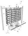
図1は、ピッキングシステムを搬送装置側から示す斜視図である。
(Embodiment 1)
FIG. 1 is a perspective view showing the picking system from the conveying device side.
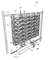
図2は、ピッキングシステムを作業者側から示す斜視図である。 FIG. 2 is a perspective view showing the picking system from the operator side.
同図に示すように、ピッキングシステム100は、保管された複数の容器200内にそれぞれ収容される物品201を作業者300が選択的に取り出すピッキングシステムである。具体的にピッキングシステムとは、例えば、一つの容器200には同一種類の物品201が複数個収容されており、物品201の種類に応じて複数の容器200が保管されている。作業者300は、保管されている容器200の中から指示された物品201の種類が収容されている容器200を選び出し、該当する容器200から指示された物品201を指示された個数取り出す。これらの作業を繰り返し、複数種類の物品201の群をひとまとまりとして搬出する。以上のようなピッキング作業の効率化を図るためのシステムがピッキングシステムである。
As shown in the figure, the
ピッキングシステム100は、保管棚101と、搬送装置102と、作業台103と、移載装置104とを備えている。
The
保管棚101は、上下方向(図中Z軸方向)、および、横方向(水平面内の所定の方向、図中X軸方向)に所定の物品201が収容される容器200を並べて保持可能な吊り下げ式の棚である。本実施の形態の場合、保管棚101は、建屋の支柱241、または、別途設けた支柱241などに張り渡された梁部材203に吊り下げられた状態で取り付けられる棚であり、支柱241が取り付けられる基礎部204からは所定の空間(下方空間)を隔てて配置されている。
The
このような吊り下げ式の保管棚101は、高い免震効果を得ることができ、地震発生時において保管棚101から容器200が落下することを可及的に防止することが可能となる。
Such a suspension-
また、保管棚101は、搬送装置102との間で容器200を移載する側とは反対側の面に、筋交い(ブレス)が設けられており、少なくとも容器200が保管される部分の全てに筋交いが設けられている。
Further, the
これによれば、ブレス欠陥のない保管棚101となり、保管棚101の構造的強度を高く維持することが可能となる。
According to this, it becomes the
本実施の形態の場合、保管棚101は、水平面内に拡がる棚板が上下方向に複数段備えており、容器200を載置状態で保管するものとなっている。
In the case of the present embodiment, the
なお、図には保管棚101は、一つしか示されていないが、搬送装置102を挟んだ反対側にも保管棚101が配置されていても良く、搬送装置102に沿って複数の保管棚101が配置されていてもよい。
Although only one
搬送装置102は、保管棚101に沿って移動し、保管棚101に沿って容器200を搬送することのできる装置である。本実施の形態の場合、保管棚101が上下方向(図中Z軸方向)、および、左右方向(図中X軸方向)に容器200を並べて保管可能であり、搬送装置102は、容器200を上下方向、および、左右方向に二次元的に搬送することのできるいわゆるスタッカクレーンが採用されている。
The
なお、搬送装置102は、スタッカクレーンに限定されるばかりでなく、例えば、保管棚101の各段に沿ってそれぞれ走行し、容器200を搬送する複数の搬送車と、複数の前記搬送車との間で容器200をそれぞれ移載することができ、かつ、容器200を上下方向に搬送することのできる垂直コンベアとを備える搬送装置102などを採用してもかまわない。
The
移載装置104は、保管棚101と搬送装置102との間で容器200を移載することができ、作業台103と搬送装置102との間でも容器200を移載することができる装置である。本実施の形態の場合、移載装置104は、搬送装置102に取り付けられており、搬送装置102により上下方向、および、左右方向に自在に移動できるものとなっている。
The
移載装置104の具体的な移載方法は特に限定されるものではないが、例えば、フォークを水平面内に出没させて容器200を移載するものや、移載する側と移載される側の載置面を同じレベルにしておき容器200を押したり引いたりすることで移載するもの、容器200を吊り下げて保持する機構を備え、容器200を吊り下げた状態で移動させ吊り下げた状態を解放することで移載するものなどを例示することができる。
Although the specific transfer method of the
作業台103は、保管棚101、および、搬送装置102の少なくとも一方の下方であって、作業者300が作業する作業領域内に配置される台である。本実施の形態の場合、作業台103は、保管棚101の容器200が載置されている棚板の下方に棚板と同様の状態で配置されており、移載装置104により保管棚101と搬送装置102との間における移載状態と同じ状態で搬送装置102との間で容器200が移載されるものとなっている。
The work table 103 is a table disposed below the
以上のピッキングシステム100によれば、作業者300がピッキング作業をするための作業台103が、保管棚101の下方空間に配置されているため、作業者300の作業領域を広く確保できるにもかかわらずピッキングシステム100がコンパクトとなり、建屋内においてピッキング作業に要する面積を狭くすることが可能となる。
According to the
また、作業者300が保管棚101に保管されている容器200に直接アクセスすることが無いため、保管棚101の片側全面に筋交いなど構造的強度を高める部材を設けることができ、作業者300側への容器200の落下を防止することが可能となる。
In addition, since the
また、保管棚101との移載状態と同じ状態で作業台103とも移載することができるため、汎用的な移載装置104をピッキングシステム100に採用することが可能となる。
In addition, since the work table 103 can be transferred in the same state as the transfer state with the
(実施の形態2)
続いて、実施の形態2について説明する。なお、実施の形態1と同様の作用や機能、同様の形状や機構や構造を有するもの(部分)には同じ符号を付して説明を省略する場合がある。また、以下では実施の形態1と異なる点を中心に説明し、同じ内容については説明を省略する場合がある。
(Embodiment 2)
Next, the second embodiment will be described. In addition, the same code | symbol may be attached | subjected to what has the effect | action and function similar to Embodiment 1, and the same shape, mechanism, and structure (part) may be abbreviate | omitted. In the following description, differences from the first embodiment will be mainly described, and description of the same contents may be omitted.
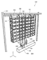
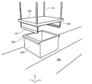
図3は、他の実施の形態に係るピッキングシステムを搬送装置側から示す斜視図である。 FIG. 3 is a perspective view showing a picking system according to another embodiment from the conveying device side.
同図に示すように、本実施の形態の場合、ピッキングシステム100は、吊り下げ式の搬送装置102を備えている。搬送装置102は、基礎部204の上方(天井側)に張り渡された軌条121に沿って走行する走行車122と、走行車122に対しワイヤーなどの吊り部材124により吊り下げられた状態で昇降し容器200を保持することができる昇降台123を備えている。
As shown in the figure, in the case of the present embodiment, the
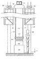
図4は、他の実施の形態に係るピッキングシステムを側方から示す平面図である。 FIG. 4 is a plan view showing a picking system according to another embodiment from the side.
同図に示すように、作業台103は、搬送装置102が移動する領域の下方領域(軌条121の下方領域)に配置されている。
As shown in the figure, the work table 103 is disposed in a lower region (a lower region of the rail 121) of the region in which the
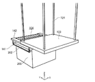
図5は、他の実施の形態に係る移載装置の一方の移載状態を示す斜視図である。 FIG. 5 is a perspective view showing one transfer state of the transfer apparatus according to another embodiment.
図6は、他の実施の形態に係る移載装置の他方の移載状態を示す斜視図である。 FIG. 6 is a perspective view showing the other transfer state of the transfer device according to another embodiment.
これらの図に示すように、移載装置104は、搬送装置102の下方、昇降台123の移動領域の直下に配置される作業台103との間で容器200を移載することができるものとなっている。本実施の形態の場合、移載装置104は、図5に示すように、昇降台123から作業台103に向かう方向(図中Z軸方向)である第一軸方向に容器200を移載することができ、かつ、図6に示すように、昇降台123から保管棚101に向かう方向(図中Y軸方向)である第二軸方向にも容器200を移載することができるものとなっている。つまり本実施の形態に係る移載装置104は、第一軸、および、第一軸とは異なる方向の第二軸のいずれの方向にも容器200を移載することができるものである。
As shown in these drawings, the
具体的に本実施の形態の場合、移載装置104は、容器200に設けられた係合部202と係合し、かつ、自らが回転などすることにより係合を解除することのできる鈎部141を備えている。移載装置104は、作業台103に載置された状態の容器200の係合部202と鈎部141との係合を解除し、また、係合させることで昇降台123と作業台103との間で容器200を移載することができ、一方、係合部202と鈎部141とを係合させた状態でアーム142を昇降台123に対して出没させることにより、容器200を第二軸方向に移載することができる。
Specifically, in the case of the present embodiment, the
以上のピッキングシステム100によれば、作業者300がピッキング作業をするための作業領域が、保管棚101の下方空間に配置されるため、作業領域を広く確保することができるにもかかわらずピッキングシステム100を含むピッキング作業に要する領域全体がコンパクトとなる。
According to the
なお、本願発明は、上記実施の形態に限定されるものではない。例えば、本明細書において記載した構成要素を任意に組み合わせて、また、構成要素のいくつかを除外して実現される別の実施の形態を本願発明の実施の形態としてもよい。また、上記実施の形態に対して本願発明の主旨、すなわち、請求の範囲に記載される文言が示す意味を逸脱しない範囲で当業者が思いつく各種変形を施して得られる変形例も本願発明に含まれる。 In addition, this invention is not limited to the said embodiment. For example, another embodiment realized by arbitrarily combining the components described in this specification and excluding some of the components may be used as an embodiment of the present invention. In addition, the present invention includes modifications obtained by making various modifications conceivable by those skilled in the art without departing from the gist of the present invention, that is, the meaning described in the claims. It is.
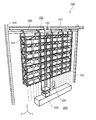
なお、ピッキングシステム100は図7に示すように、搬送装置102の横方向(図中X軸方向)の移動方向に並んだ状態で保管棚101に取り付けられ、保管棚101の下方の人の存在を検知する人感センサ105を備えてもかまわない。
As shown in FIG. 7, the
この場合、作業者300が保管棚101に沿って延在する作業台103のどの位置に存在しているかを人感センサ105を用いて検出し、作業者300が存在する位置およびその近傍の作業台103には、昇降台123や昇降台123に保持された容器200を移載しない制御をしてもかまわない。
In this case, the
本願発明は、複数の容器からそれぞれ物品をピッキングし複数種類の物品をひとまとまりにするピッキング作業に利用可能である。 The present invention can be used for a picking operation in which articles are picked from a plurality of containers and a plurality of kinds of articles are collected.
100 ピッキングシステム
101 保管棚
102 搬送装置
103 作業台
104 移載装置
105 人感センサ
121 軌条
122 走行車
123 昇降台
124 吊り部材
141 鈎部
142 アーム
200 容器
201 物品
202 係合部
203 梁部材
204 基礎部
241 支柱
300 作業者
DESCRIPTION OF
Claims (3)
上下方向、および、横方向に前記容器を並べて保持可能な吊り下げ式の保管棚と、
前記保管棚に沿って移動し、前記容器を搬送する吊り下げ式の搬送装置と、
前記搬送装置の下方であって、作業者が作業する作業領域内に配置される作業台と、
前記保管棚と前記搬送装置との間、および、前記搬送装置の直下に配置される前記作業台と前記搬送装置との間で前記容器を移載する移載装置とを備える
ピッキングシステム。 A picking system in which an operator selectively takes out articles respectively contained in a plurality of stored containers,
A suspended storage shelf that can hold the containers side by side in the vertical direction and the horizontal direction;
A suspended transfer device that moves along the storage shelf and transfers the container;
A work table disposed below the transfer device and in a work area where an operator works,
A picking system comprising: a transfer device that transfers the container between the storage shelf and the transfer device, and between the work table and the transfer device arranged immediately below the transfer device.
上下方向、および、横方向に前記容器を並べて保持可能な吊り下げ式の保管棚と、 A suspended storage shelf that can hold the containers side by side in the vertical direction and the horizontal direction;
前記保管棚に沿って移動し、前記容器を搬送する搬送装置と、 A transport device that moves along the storage shelf and transports the container;
前記保管棚、および、前記搬送装置の少なくとも一方の下方であって、作業者が作業する作業領域内に配置される作業台と、 A workbench disposed below the storage shelf and at least one of the transfer devices and in a work area where an operator works;
前記保管棚と前記搬送装置との間、および、前記作業台と前記搬送装置との間で前記容器を移載する移載装置と、 A transfer device for transferring the container between the storage shelf and the transfer device, and between the work table and the transfer device;
前記搬送装置の横方向の移動方向に並んだ状態で前記保管棚に取り付けられ、前記保管棚下方の人の存在を検知する人感センサと A human sensor that is attached to the storage shelf in a state of being aligned in the lateral movement direction of the transport device and detects the presence of a person below the storage shelf;
を備えるピッキングシステム。Picking system with
請求項2に記載のピッキングシステム。The picking system according to claim 2.
Priority Applications (1)
| Application Number | Priority Date | Filing Date | Title |
|---|---|---|---|
| JP2015000460A JP6476868B2 (en) | 2015-01-05 | 2015-01-05 | Picking system |
Applications Claiming Priority (1)
| Application Number | Priority Date | Filing Date | Title |
|---|---|---|---|
| JP2015000460A JP6476868B2 (en) | 2015-01-05 | 2015-01-05 | Picking system |
Publications (2)
| Publication Number | Publication Date |
|---|---|
| JP2016124677A JP2016124677A (en) | 2016-07-11 |
| JP6476868B2 true JP6476868B2 (en) | 2019-03-06 |
Family
ID=56358770
Family Applications (1)
| Application Number | Title | Priority Date | Filing Date |
|---|---|---|---|
| JP2015000460A Expired - Fee Related JP6476868B2 (en) | 2015-01-05 | 2015-01-05 | Picking system |
Country Status (1)
| Country | Link |
|---|---|
| JP (1) | JP6476868B2 (en) |
Families Citing this family (2)
| Publication number | Priority date | Publication date | Assignee | Title |
|---|---|---|---|---|
| CN109720765A (en) * | 2019-01-26 | 2019-05-07 | 西安威仁自动化科技有限公司 | A kind of automatic access material device |
| JP7580101B2 (en) * | 2020-03-02 | 2024-11-11 | 伊東電機株式会社 | Warehouse Equipment |
Family Cites Families (4)
| Publication number | Priority date | Publication date | Assignee | Title |
|---|---|---|---|---|
| JP2662837B2 (en) * | 1991-12-24 | 1997-10-15 | 璋 伊東 | Shelf lifting device |
| JPH06277122A (en) * | 1993-03-29 | 1994-10-04 | Kajima Corp | Storing equipment utilizing empty space |
| JP3333273B2 (en) * | 1993-05-28 | 2002-10-15 | 麒麟麦酒株式会社 | Picking equipment |
| JP5316844B2 (en) * | 2008-07-01 | 2013-10-16 | 株式会社ダイフク | Goods storage equipment |
-
2015
- 2015-01-05 JP JP2015000460A patent/JP6476868B2/en not_active Expired - Fee Related
Also Published As
| Publication number | Publication date |
|---|---|
| JP2016124677A (en) | 2016-07-11 |
Similar Documents
| Publication | Publication Date | Title |
|---|---|---|
| JP7057370B2 (en) | Automatic storage and recovery system | |
| TWI722208B (en) | Transport system | |
| TWI828841B (en) | custody system | |
| RU2555083C2 (en) | Suspended robot-aided system, and its operating method | |
| JP6222135B2 (en) | Automatic warehouse | |
| TWI714809B (en) | Transport system | |
| CN113195379B (en) | Storage system | |
| TW201940396A (en) | Stocker system | |
| JP6915366B2 (en) | Tracked carrier system | |
| CN101104473A (en) | Article storing device | |
| WO2021215132A1 (en) | Automated warehouse system | |
| JP2016210518A (en) | Automated warehouse and operation method of the same | |
| JP6476868B2 (en) | Picking system | |
| JP2018154479A (en) | Multi-tier automatic warehouse | |
| JP2019006517A (en) | Package delivery system | |
| JP2017165513A (en) | Picking system | |
| JP5966588B2 (en) | Transfer equipment for cart | |
| JP2011246223A (en) | Automatic warehouse | |
| JP2018080028A (en) | Automated warehouse | |
| JP2017109284A (en) | Work-piece conveyance system, laser processing system, method for conveying work-piece | |
| JP2010241547A (en) | Traveling vehicle system | |
| JP6256174B2 (en) | Automatic warehouse | |
| JP2019123614A (en) | Container crane and cargo handling method by container crane | |
| JP4834128B2 (en) | Transport system | |
| JP4834127B2 (en) | Transport system |
Legal Events
| Date | Code | Title | Description |
|---|---|---|---|
| A621 | Written request for application examination |
Free format text: JAPANESE INTERMEDIATE CODE: A621 Effective date: 20171023 |
|
| A977 | Report on retrieval |
Free format text: JAPANESE INTERMEDIATE CODE: A971007 Effective date: 20180809 |
|
| A131 | Notification of reasons for refusal |
Free format text: JAPANESE INTERMEDIATE CODE: A131 Effective date: 20180821 |
|
| A521 | Request for written amendment filed |
Free format text: JAPANESE INTERMEDIATE CODE: A523 Effective date: 20180921 |
|
| TRDD | Decision of grant or rejection written | ||
| A01 | Written decision to grant a patent or to grant a registration (utility model) |
Free format text: JAPANESE INTERMEDIATE CODE: A01 Effective date: 20190108 |
|
| A61 | First payment of annual fees (during grant procedure) |
Free format text: JAPANESE INTERMEDIATE CODE: A61 Effective date: 20190121 |
|
| R150 | Certificate of patent or registration of utility model |
Ref document number: 6476868 Country of ref document: JP Free format text: JAPANESE INTERMEDIATE CODE: R150 |
|
| R250 | Receipt of annual fees |
Free format text: JAPANESE INTERMEDIATE CODE: R250 |
|
| R250 | Receipt of annual fees |
Free format text: JAPANESE INTERMEDIATE CODE: R250 |
|
| LAPS | Cancellation because of no payment of annual fees |