JP6476744B2 - Transport device - Google Patents
Transport device Download PDFInfo
- Publication number
- JP6476744B2 JP6476744B2 JP2014217391A JP2014217391A JP6476744B2 JP 6476744 B2 JP6476744 B2 JP 6476744B2 JP 2014217391 A JP2014217391 A JP 2014217391A JP 2014217391 A JP2014217391 A JP 2014217391A JP 6476744 B2 JP6476744 B2 JP 6476744B2
- Authority
- JP
- Japan
- Prior art keywords
- article
- unit
- transport
- processing
- unloading
- Prior art date
- Legal status (The legal status is an assumption and is not a legal conclusion. Google has not performed a legal analysis and makes no representation as to the accuracy of the status listed.)
- Expired - Fee Related
Links
Images


Classifications
-
- B—PERFORMING OPERATIONS; TRANSPORTING
- B23—MACHINE TOOLS; METAL-WORKING NOT OTHERWISE PROVIDED FOR
- B23Q—DETAILS, COMPONENTS, OR ACCESSORIES FOR MACHINE TOOLS, e.g. ARRANGEMENTS FOR COPYING OR CONTROLLING; MACHINE TOOLS IN GENERAL CHARACTERISED BY THE CONSTRUCTION OF PARTICULAR DETAILS OR COMPONENTS; COMBINATIONS OR ASSOCIATIONS OF METAL-WORKING MACHINES, NOT DIRECTED TO A PARTICULAR RESULT
- B23Q7/00—Arrangements for handling work specially combined with or arranged in, or specially adapted for use in connection with, machine tools, e.g. for conveying, loading, positioning, discharging, sorting
- B23Q7/14—Arrangements for handling work specially combined with or arranged in, or specially adapted for use in connection with, machine tools, e.g. for conveying, loading, positioning, discharging, sorting co-ordinated in production lines
- B23Q7/1426—Arrangements for handling work specially combined with or arranged in, or specially adapted for use in connection with, machine tools, e.g. for conveying, loading, positioning, discharging, sorting co-ordinated in production lines with work holders not rigidly fixed to the transport devices
- B23Q7/1463—Arrangements for handling work specially combined with or arranged in, or specially adapted for use in connection with, machine tools, e.g. for conveying, loading, positioning, discharging, sorting co-ordinated in production lines with work holders not rigidly fixed to the transport devices using rotary driving means
-
- B—PERFORMING OPERATIONS; TRANSPORTING
- B23—MACHINE TOOLS; METAL-WORKING NOT OTHERWISE PROVIDED FOR
- B23Q—DETAILS, COMPONENTS, OR ACCESSORIES FOR MACHINE TOOLS, e.g. ARRANGEMENTS FOR COPYING OR CONTROLLING; MACHINE TOOLS IN GENERAL CHARACTERISED BY THE CONSTRUCTION OF PARTICULAR DETAILS OR COMPONENTS; COMBINATIONS OR ASSOCIATIONS OF METAL-WORKING MACHINES, NOT DIRECTED TO A PARTICULAR RESULT
- B23Q41/00—Combinations or associations of metal-working machines not directed to a particular result according to classes B21, B23, or B24
- B23Q41/02—Features relating to transfer of work between machines
-
- B—PERFORMING OPERATIONS; TRANSPORTING
- B23—MACHINE TOOLS; METAL-WORKING NOT OTHERWISE PROVIDED FOR
- B23Q—DETAILS, COMPONENTS, OR ACCESSORIES FOR MACHINE TOOLS, e.g. ARRANGEMENTS FOR COPYING OR CONTROLLING; MACHINE TOOLS IN GENERAL CHARACTERISED BY THE CONSTRUCTION OF PARTICULAR DETAILS OR COMPONENTS; COMBINATIONS OR ASSOCIATIONS OF METAL-WORKING MACHINES, NOT DIRECTED TO A PARTICULAR RESULT
- B23Q7/00—Arrangements for handling work specially combined with or arranged in, or specially adapted for use in connection with, machine tools, e.g. for conveying, loading, positioning, discharging, sorting
- B23Q7/14—Arrangements for handling work specially combined with or arranged in, or specially adapted for use in connection with, machine tools, e.g. for conveying, loading, positioning, discharging, sorting co-ordinated in production lines
- B23Q7/1426—Arrangements for handling work specially combined with or arranged in, or specially adapted for use in connection with, machine tools, e.g. for conveying, loading, positioning, discharging, sorting co-ordinated in production lines with work holders not rigidly fixed to the transport devices
- B23Q7/1463—Arrangements for handling work specially combined with or arranged in, or specially adapted for use in connection with, machine tools, e.g. for conveying, loading, positioning, discharging, sorting co-ordinated in production lines with work holders not rigidly fixed to the transport devices using rotary driving means
- B23Q7/1468—Arrangements for handling work specially combined with or arranged in, or specially adapted for use in connection with, machine tools, e.g. for conveying, loading, positioning, discharging, sorting co-ordinated in production lines with work holders not rigidly fixed to the transport devices using rotary driving means comprising rollers or cogwheels, or pinions or the like
Description
本発明は、物品に対して所定の処理を施す複数の処理装置により構成される生産ラインに用いられ、搬送路上の物品を搬送する搬送装置に関するものである。 The present invention relates to a transport apparatus for transporting an article on a transport path, which is used in a production line including a plurality of processing apparatuses that perform predetermined processing on an article.
搬送装置は、例えば特許文献1,2に示すように、加工処理を施す工作機械に対して工作物の搬入および搬出を行うとともに、工作機械間の工作物の搬送に用いられる。このような搬送装置は、例えば特許文献1の図2、および特許文献2の図10に示すように、工作物を搬送方向の両側から把持する把持部材と、当該把持部材を搬送方向に移動させる駆動装置とを備える。また、複数の工作機械により生産ラインが構成される場合には、複数の搬送装置を連携して動作可能な搬送システムが当該生産ラインに用いられる。 For example, as shown in Patent Literatures 1 and 2, the transfer device is used to transfer a workpiece to and from a machine tool to be processed, and to transfer the workpiece between the machine tools. For example, as shown in FIG. 2 of Patent Document 1 and FIG. 10 of Patent Document 2, such a transport apparatus moves a gripping member that grips a workpiece from both sides in the transport direction and the gripping member in the transport direction. And a drive unit. In addition, when a production line is configured by a plurality of machine tools, a transport system that can operate in cooperation with a plurality of transport devices is used for the production line.
工作機械間に配置される搬送装置は、特許文献1のように工作機械間をベルトコンベアにより工作物を搬送する構成では、上流側の工作機械から工作物を搬出するユニットと、下流側の工作機械に工作物を搬入するユニットが干渉しないように配置する必要がある。そのため、搬送装置が全体として搬送方向に大型化し、搬送路により連結される工作機械間の距離が大きくなる。そうすると、工場内における工作機械のレイアウトの設定自由度が低下する。 In the configuration in which the transport device disposed between the machine tools is configured to transport the workpiece by the belt conveyor between the machine tools as in Patent Document 1, a unit for unloading the workpiece from the upstream machine tool, and the downstream machine It is necessary to arrange so that the unit which carries in a work to a machine does not interfere. Therefore, the transport device as a whole is enlarged in the transport direction, and the distance between the machine tools connected by the transport path is increased. Then, the setting freedom of the layout of the machine tool in the factory is reduced.
本発明は、このような事情に鑑みてなされたものであり、装置の小型化を図ることにより、処理装置間の距離を小さくすることが可能な搬送装置を提供することを目的とする。 The present invention has been made in view of such circumstances, and it is an object of the present invention to provide a transport apparatus capable of reducing the distance between processing apparatuses by miniaturizing the apparatus.
(請求項1)本発明に係る搬送装置は、搬送路上に載置された物品に対して所定の処理を施す第一処理装置および第二処理装置が前記物品の搬送方向に並んで設置されることにより構成される生産ラインに用いられ、前記搬送路上の前記物品を搬送する。搬送装置は、前記第一処理装置の機内から前記物品を機外まで搬出する搬出ユニットと、前記第二処理装置の機外から前記物品を機内まで搬入する搬入ユニットと、を備える。前記搬出ユニットおよび前記搬入ユニットは、搬送方向に重複した位置に配置され、且つ前記物品を搬送方向に移動可能とするそれぞれの搬送領域が搬送方向に連続する位置にそれぞれ配置される。前記搬出ユニットおよび前記搬入ユニットは、前記搬送路の上方に配置され、前記搬送路の上面から所定の高さにおいて前記物品に係止して当該物品に搬送方向の外力を付与する係止部材と、前記係止部材を支持するとともに、当該係止部材を搬送方向に移動させる駆動装置と、をそれぞれ有する。前記搬出ユニットおよび前記搬入ユニットの各前記係止部材は、前記搬送路の幅方向の一方側および他方側に互いに離間して配置され、前記駆動装置に支持される基端部と、前記基端部よりも前記搬送路の幅方向中央側に配置され前記物品に係止する爪部と、前記基端部と前記爪部を連結する連結部と、をそれぞれ有する。
(請求項2)本発明に係る搬送装置は、搬送路上に載置された物品に対して所定の処理を施す第一処理装置および第二処理装置が前記物品の搬送方向に並んで設置されることにより構成される生産ラインに用いられ、前記搬送路上の前記物品を搬送する。搬送装置は、前記第一処理装置の機内から前記物品を機外まで搬出する搬出ユニットと、前記第二処理装置の機外から前記物品を機内まで搬入する搬入ユニットと、を備える。前記搬出ユニットおよび前記搬入ユニットは、搬送方向に重複した位置に配置され、且つ前記物品を搬送方向に移動可能とするそれぞれの搬送領域が搬送方向に連続する位置にそれぞれ配置される。前記搬送装置は、前記搬入ユニットであって前記第一処理装置の機外から前記物品を機内まで搬入する第一搬入ユニットと、前記搬出ユニットであって前記第一処理装置の機内から前記物品を機外まで搬出する第一搬出ユニットと、前記搬入ユニットであって前記第二処理装置の機外から前記物品を機内まで搬入する第二搬入ユニットと、を備える。前記第一搬入ユニットは、前記第一処理装置の機外から前記搬送路上の規定位置まで処理前の前記物品を搬入するとともに、当該搬入動作において前記規定位置に載置された処理後の前記物品に処理前の前記物品を押し付けることによって、処理後の前記物品を前記搬送路上の搬出待機位置まで移動させる。前記第一搬出ユニットは、前記搬出待機位置に載置された処理後の前記物品を前記第一処理装置の機外まで搬出する。
(Claim 1) In the transport apparatus according to the present invention, a first processing apparatus and a second processing apparatus for performing predetermined processing on an article placed on a transport path are installed side by side in the transport direction of the article And transport the articles on the transport path. The transport apparatus includes a carry-out unit for carrying the article out of the machine of the first processing apparatus to the outside of the machine, and a carry-in unit for carrying the article into the machine from the outside of the machine of the second processing apparatus. The carry-out unit and the carry-in unit are disposed at overlapping positions in the transport direction, and the respective transport areas for moving the article in the transport direction are respectively disposed at continuous positions in the transport direction. The carry-out unit and the carry-in unit are disposed above the transport path, and engage with the article at a predetermined height from the upper surface of the transport path to apply an external force in the transport direction to the article And a driving device for supporting the locking member and moving the locking member in the transport direction. The locking members of the carry-out unit and the carry-in unit are disposed apart from each other on one side and the other side in the width direction of the transport path, and a base end supported by the drive device; It has a claw part which is arranged on the widthwise center side of the transport path rather than a part and which is engaged with the article, and a connecting part which connects the base end and the claw.
(Claim 2) In the conveying device according to the present invention, a first processing device and a second processing device for performing predetermined processing on an article placed on a conveying path are installed side by side in the conveying direction of the article And transport the articles on the transport path. The transport apparatus includes a carry-out unit for carrying the article out of the machine of the first processing apparatus to the outside of the machine, and a carry-in unit for carrying the article into the machine from the outside of the machine of the second processing apparatus. The carry-out unit and the carry-in unit are disposed at overlapping positions in the transport direction, and the respective transport areas for moving the article in the transport direction are respectively disposed at continuous positions in the transport direction. The transport device is the loading unit, and a first loading unit for loading the article into the machine from outside the first processing device; and the unloading unit, the article from the inside of the machine of the first processing device A first unloading unit for unloading the apparatus to the outside of the machine, and a second loading unit for carrying the article into the machine from the outside of the apparatus of the second processing device, which is the loading unit. The first loading unit carries in the article before processing from outside the machine of the first processing apparatus to a prescribed position on the transport path, and the article after processing placed at the prescribed position in the loading operation. By pressing the article before the treatment, the article after the treatment is moved to the unloading standby position on the transport path. The first unloading unit unloads the processed article placed at the unloading standby position to the outside of the first processing apparatus.
請求項1に記載の本発明によると、搬出ユニットおよび搬入ユニットは、隣り合う第一処理装置と第二処理装置との間に搬送方向に並列に配置される。これにより、各ユニットを搬送方向に直列に配置する構成と比較して、両ユニットの配置に要する搬送方向幅を短縮できる。よって、搬送装置全体として小型化を図ることにより、処理装置間の距離を小さくすることが可能となる。 According to the first aspect of the present invention, the unloading unit and the loading unit are arranged in parallel in the transport direction between the adjacent first processing device and second processing device. Thereby, the width in the conveyance direction required for the arrangement of both units can be shortened as compared with the configuration in which the units are arranged in series in the conveyance direction. Therefore, the distance between the processing devices can be reduced by miniaturizing the entire transport device.
以下、本発明の搬送装置を具体化した実施形態について図面を参照して説明する。搬送装置は、搬送路上の物品を搬送する装置であって、物品に対して処理を施す処理装置に用いられる。なお、実施形態においては、処理装置は工作機械であり、所定の加工処理としてワーク(物品)に対して加工処理を行う態様を例示する。また、搬送装置は、複数の工作機械により構成される生産ラインに用いられる。 Hereinafter, an embodiment in which the transfer device of the present invention is embodied will be described with reference to the drawings. The transport apparatus is an apparatus for transporting an article on a transport path, and is used for a processing apparatus that processes the article. In the embodiment, the processing apparatus is a machine tool, and a mode of performing processing on a work (article) as a predetermined processing is exemplified. Moreover, a conveyance apparatus is used for the production line comprised with several machine tools.
<実施形態>
(1.生産ライン10および搬送装置30の全体構成)
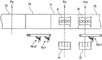
生産ライン10および搬送装置30の全体構成について、図1および図2を参照して説明する。生産ライン10は、図1に示すように、3台の工作機械11〜13と、搬送装置30とを備える。工作機械11〜13は、同種の工作機械であって、搬送路70上の規定位置Ppに載置されたワークW(本発明の「物品」に相当する)をクランプして、切削加工などの加工処理を施す処理装置である。3台の工作機械11〜13は、所定の間隔を空けて、搬送方向に並んで設置され、生産ライン10を構成する。
Embodiment
(1. Overall Configuration of
The entire configuration of the
ここで、3台の工作機械11〜13のうち生産ライン10の最上流側に設置された工作機械を第一工作機械11(本発明の「第一処理装置」に相当する)とする。第一工作機械11は、ベッド21に対してX軸方向(図1の左右方向)に移動可能にコラム22を有する。コラム22の前面には、当該コラム22に対してY軸方向(図1の前後方向)に移動可能にサドル23が設けられる。サドル23の前面には、当該サドルに対してZ軸方向(図1の上下方向)に移動可能な回転主軸24に回転工具25が保持される。
Here, among the three
第一工作機械11は、搬送路70上の規定位置Ppに載置されたワークWを、リフタ26により昇降させる。リフタ26は、加工処理前のワークWを搬送路70の下方に移動させてチルト装置27の上面のクランプ位置に載置する。第一工作機械11は、図略のクランプ装置によりワークWを位置決め固定する。第一工作機械11は、コラム22やサドル2、チルト装置27などの動作により、ワークWに対して回転工具25を相対移動させて加工処理を行う。リフタ26は、チルト装置27に対してアンクランプされた加工処理後のワークWを上方に移動させて、搬送路70上の規定位置Ppに戻す。
The
また、3台の工作機械11〜13のうち第一工作機械11に対して生産ライン10の下流側に順に設置された2台の工作機械を第二工作機械12(本発明の「第二処理装置」に相当する)および第三工作機械13とする。第二工作機械12および第三工作機械13は、第一工作機械11と同様に、搬送路70上の規定位置Ppに載置されたワークWをそれぞれのリフタ26により搬送路70に対して昇降させる。第二工作機械12および第三工作機械13は、それぞれのチルト装置27に位置決め固定されたワークWに対して加工処理を行う。
Further, of the three
ここで、上記の「規定位置」とは、工作機械の機内において、各工作機械が加工処理を行うために搬送装置30との間でワークWの受け渡し可能な搬送路上の位置に相当する。つまり、工作機械が、例えばリフタ26に換えてパレットチェンジャにより搬送路上のワークWをクランプ位置に移動させる場合には、搬送路上の「規定位置」は、パレットチェンジャと搬送装置30がワークWを受け渡し可能な位置に相当する。また、搬送路上の規定位置においてワークWをクランプして加工処理を実行する場合には、搬送路上の「規定位置」は、ワークWのクランプ位置に相当する。
Here, the above-mentioned "prescribed position" corresponds to a position on the transport path on which the workpiece W can be delivered to / from the
搬送装置30は、複数の搬入ユニットNmと、複数の搬出ユニットNxと、複数の機内搬送台71〜73と、複数の機外搬送台75〜77と、回転テーブル80とを備える。複数の搬入ユニットNmは、生産ライン10の上流側から順に第一搬入ユニットNm1、第二搬入ユニットNm2、および第三搬入ユニットNm3とする。また、複数の搬出ユニットNxは、生産ライン10の上流側から順に第一搬出ユニットNx1、第二搬出ユニットNx2、第三搬出ユニットNx3とする。
The
第一搬入ユニットNm1は、第一工作機械11に対してワークWを搬入する。第一搬出ユニットNx1は、第一工作機械11により加工処理されたワークWを搬出する。第二搬入ユニットNm2は、第二工作機械12に対してワークWを搬入する。第二搬出ユニットNx2は、第二工作機械12により加工処理されたワークWを搬出する。第三搬入ユニットNm3は、第三工作機械13に対してワークWを搬入する。第三搬出ユニットNx3は、第三工作機械13により加工処理されたワークWを搬出する。搬入ユニットNm1〜Nm3および搬出ユニットNx1〜Nx3の詳細構成については後述する。
The first loading unit Nm1 loads the work W into the
複数の機内搬送台71〜73は、対応する第一工作機械11、第二工作機械12、および第三工作機械13の機内にそれぞれ設けられる。複数の機外搬送台75〜77は、図1に示すように、第一工作機械11、第二工作機械12、および第三工作機械13の上流側または下流側にそれぞれ設けられる。回転テーブル80は、第二工作機械12と第三工作機械13との間に配置される。
The plurality of in-machine transfer tables 71 to 73 are respectively provided in the corresponding
複数の機内搬送台71〜73、複数の機外搬送台75〜77、および回転テーブル80は、上面にワーク搬送面を備え、搬送路70の一部をそれぞれ構成する。ワーク搬送面には、図示しない摺動ガイドまたは転動ガイドが設けられる。これにより、搬送路70は、各ワーク搬送面におけるワークWの手動搬送を可能とする。
The plurality of in-machine conveyance tables 71 to 73, the plurality of out-of-machine conveyance tables 75 to 77, and the rotary table 80 have work conveyance surfaces on the upper surface, and constitute a part of the
また、回転テーブル80は、図1および図2に示すように、転動ガイド81と、引出機構82と、回転機構83とを有する。転動ガイド81は、搬送方向に並んで配置された複数のローラ部材により構成される。引出機構82は、回転テーブル80の本体部に対して転動ガイド81を搬送路70に直交する水平方向に移動可能とする機構である。回転機構83は、回転テーブル80の本体部に対して転動ガイド81を鉛直な中心軸周りに回転可能とする機構である。
Further, as shown in FIGS. 1 and 2, the rotary table 80 has a rolling
このような構成により、回転テーブル80は、転動ガイド81にワークWが載置された状態で、当該ワークWを搬送路70から側方に移動させ、その位置でワークWを鉛直な中心軸周りに回転させることができる。これにより、回転テーブル80よりも上流側に設置された第一工作機械11および第二工作機械12により加工処理されたワークWについて、搬送路70の側方からワークWの全周に亘る視認が可能となる。また、回転機構83の回転により転動ガイド81によるワークWの案内方向が変更され、搬送路70の外部へのワークWの持ち出しが容易となる。
With such a configuration, the rotary table 80 moves the workpiece W laterally from the
(2.搬入ユニットNm1〜Nm3および搬出ユニットNx1〜Nx3の詳細構成)
本実施形態において、各搬入ユニットNm1〜Nm3および各搬出ユニットNx1〜Nx3は、同種の搬送用ユニットである。ここでは、第一搬出ユニットNx1の構成について説明する。
(2. Detailed configuration of loading unit Nm1 to Nm3 and unloading unit Nx1 to Nx3)
In the present embodiment, the loading units Nm1 to Nm3 and the unloading units Nx1 to Nx3 are transport units of the same type. Here, the configuration of the first carry-out unit Nx1 will be described.
(2−1.第一搬出ユニットNx1について)
第一搬出ユニットNx1は、搬送路70上に載置されたワークWを搬送方向に沿って移動させる。第一搬出ユニットNx1は、図3に示すように、アンチバック機構40および駆動装置50を備える。アンチバック機構40は、搬送方向のうち搬出側(図3の左側)へのワークWの移動を許容し、且つ搬入側(図3の右側)へのワークWの移動を規制する。駆動装置50は、第一工作機械11の機外に設けられ、後述するアンチバック機構40の係止部材42を搬送方向に移動させる。
(About 2-1. 1st unloading unit Nx1)
The first unloading unit Nx1 moves the workpiece W placed on the
より具体的には、アンチバック機構40は、図4に示すように、本体部41と、係止部材42と、ストッパー部材43と、調整機構44とを有する。本体部41は、駆動装置50に固定され、当該駆動装置50の動作により搬送方向に移動する。係止部材42は、搬送路70の上方に配置され、搬送路70の上面から所定の高さにおいてワークWに係止してワークWに搬送方向の外力を付与する。係止部材42は、本体部41に対して搬送方向に直交し且つ水平な回転軸線周りに回転可能に支持される。
More specifically, as shown in FIG. 4, the
また、本実施形態において、係止部材42は、図5に示すように、基端部42aと、爪部42bと、連結部42cとを有する。基端部42aは、係止部材42における駆動装置50側の端部であって、本体部41を介して駆動装置50に間接的に支持される部位である。爪部42bは、基端部42aよりも搬送路70の幅方向(図5の左右方向)中央側に配置され、ワークWに係止する部位である。
Further, in the present embodiment, as shown in FIG. 5, the locking
連結部42cは、基端部42aと爪部42bを連結する部位である。このような構成により、係止部材42は、上端側から下端側にかけて全体として屈曲した形状を呈する。つまり、係止部材42は、本体部41に支持される基端部42aよりも、搬送路70の幅方向中央側においてワークWに搬送方向の外力を付与可能に構成される。
The
ストッパー部材43は、係止部材42が下向きにある初期状態(図4の実線で示される係止部材42の状態)において、係止部材42の反搬送方向(図4の反時計回り)の回転を規制する。このような構成によると、アンチバック機構40がワークWに対して搬入側に移動する場合には、係止部材42が回転した状態(図4の破線で示される係止部材42の状態)となる。よって、係止部材42がワークWに係止せず、アンチバック機構40は、ワークWに対する搬入方向への相対移動を許容する。
The
一方で、アンチバック機構40がワークWに対して搬出側に移動する場合には、係止部材42がストッパー部材43により回転を規制された状態となる。よって、係止部材42がワークWにおける所定の係止位置に係止し、アンチバック機構40は、ワークWに対する搬出方向への相対移動を規制する。従って、アンチバック機構40が搬出方向に移動される場合には、当該移動に伴ってワークWが係止部材42より外力を受けて搬出方向に移動される。
On the other hand, when the
調整機構44は、駆動装置50に対する係止部材42の搬送方向位置を調整可能とする機構である。本実施形態において、調整機構44は、本体部41において駆動装置50に固定される固定部材と、係止部材42を回転可能に支持する支持部材とを、所定の搬送方向範囲において連結可能としている。このような構成により、本体部41において固定部材に対する支持部材の連結位置が調整可能となる。当該調整により、搬送路70において、第一搬出ユニットNx1がワークWを搬送方向に移動可能な搬送領域Rxが設定される。
The
駆動装置50は、アンチバック機構40を搬送方向に沿って移動させる。本実施形態において、駆動装置50は、倍速機構を用いてアンチバック機構40を搬送方向に移動させる。より具体的には、駆動装置50は、図3に示すように、フレーム51と、シリンダ部材52と、シリンダロッド53と、第一可動体54と、無端ベルト55と、第二可動体56とを有する。
The driving
フレーム51は、第一工作機械11に対して相対移動不能に固定される。シリンダ部材52は、フレーム51に設けられ、例えば供給される油圧によりシリンダロッド53を搬送方向に移動させる。第一可動体54は、シリンダロッド53に一体的に設けられ、シリンダロッド53の移動に伴いフレーム51に対して搬送方向に移動可能に構成されている。無端ベルト55は、第一可動体54に設けられた2つのプーリに懸架され、外周面の一部(図3の斜線部)をフレーム51に固定されている。
The
第二可動体56は、無端ベルト55の外周面の一部に固定されている。また、第二可動体56の下部には、アンチバック機構40の本体部41が連結される。このような構成によると、シリンダ部材52の動作によりシリンダロッド53が搬出方向に移動すると、先ず第一可動体54がフレーム51に対して搬出方向に移動する。そうすると、無端ベルト55は、全体として搬出方向に移動する。このとき、無端ベルト55は、一部(図3の斜線部)をフレーム51に固定されているため、第一可動体54の移動距離に応じて固定された一部を基点に回転する。
The second movable body 56 is fixed to a part of the outer peripheral surface of the
無端ベルト55に固定されている第二可動体56は、無端ベルト55の回転によって第一可動体54に対して搬出方向に移動する。つまり、第二可動体56は、第一可動体54の搬送方向の一方側(搬出方向)への移動距離に応じて第一可動体54に対して搬送方向の一方側(搬出方向)に相対移動する。そのため、フレーム51に対する第二可動体56の移動距離は、フレーム51に対する第一可動体54の移動距離の2倍となる。第二可動体56の移動距離は、第一可動体54が搬送方向の他方側(搬入方向)に移動する場合も同様に、第一可動体54の移動距離の2倍となる。
The second movable body 56 fixed to the
上記のような構成からなる倍速機構を用いた駆動装置50は、シリンダ部材52のストロークに対して2倍の移動距離、およびシリンダロッド53の動作に対して2倍の速度で第二可動体56を移動可能とする。駆動装置50は、搬送装置30の制御装置62の指令に従って、シリンダ部材52を動作させる。これにより、駆動装置50は、第二可動体56と一体的に移動するアンチバック機構40の係止部材42を、搬送方向の所定位置に移動させる。
The driving
(2−2.第一搬入ユニットNm1について)
ここで、搬送装置30の第一搬入ユニットNm1は、上述したように、第一搬出ユニットNx1と同種の搬送用ユニットである。第一搬入ユニットNm1は、第一搬出ユニットNx1が搬送路70の一方側(図1の下側)に配置されるのに対して、搬送路70の他方側(図1の上側)に配置される。第一搬入ユニットNm1の駆動装置50および第一搬出ユニットNx1の駆動装置50は、第一工作機械11が加工処理している場合に、係止部材42を含むアンチバック機構40を第一工作機械11の機外に退避させる。
(2-2. Regarding the first loading unit Nm1)
Here, as described above, the first loading unit Nm1 of the
また、第一搬入ユニットNm1は、第一工作機械11の機外から第一工作機械11の機内の規定位置Ppまで加工処理前のワークWを搬送する。第一搬入ユニットNm1は、当該搬入動作において規定位置Ppに載置された加工処理後のワークWに加工処理前のワークWを押し付けることによって、加工処理後のワークWを搬送路70上の搬出待機位置Pxまで移動させる。第一搬出ユニットNx1は、搬出待機位置Pxに載置された加工処理後のワークWを第一工作機械11の機外まで搬出する。
In addition, the first loading unit Nm1 transports the workpiece W before the processing process from the outside of the
搬送装置30は、図2に示すように、検出部61および制御装置62を備える。検出部61は、加工処理後のワークWが搬出待機位置Pxまで移動されたか否かを検出する。制御装置62は、検出部61による検出結果に基づいて第一搬出ユニットNx1を動作させて、搬出待機位置Pxに載置されたワークWを第一工作機械11の機外に搬出させる。
The
本実施形態において、第一搬入ユニットNm1は、ワークWに係止部材42を係止させた状態で第一工作機械11の機内にワークWを押し込んで搬入する。一方で、第一搬出ユニットNx1は、本実施形態において、ワークWの係止部材42を係止させた状態で第一工作機械11の機外にワークWをかき出して搬出する。つまり、同種の搬送用ユニットである第一搬入ユニットNm1および第一搬出ユニットNx1のそれぞれの係止部材42は、ワークWの押し込みにもかき出しにも適用可能に構成される。
In the present embodiment, the first loading unit Nm1 pushes and loads the work W into the machine of the
また、第一搬入ユニットNm1および第一搬出ユニットNx1は、駆動装置50の固定位置および駆動装置50に対する係止部材42の搬送方向位置により、ワークWを搬送方向に移動可能な搬送領域Rm,Rxがそれぞれ設定される。具体的には、第一搬入ユニットNm1の搬送領域Rmは、駆動装置50によるアンチバック機構40の可動範囲に応じた領域(搬入待機位置Pmから規定位置Ppまでの領域)に、加工処理前のワークWの押し付けによる加工処理後のワークWの移動領域(規定位置Ppから搬出待機位置Pxまでの領域)を加えた領域に相当する。第一搬出ユニットNx1の搬送領域Rxは、搬送路70上の搬出待機位置Pxから第二工作機械12に対する搬入待機位置Pmまでの領域である。
Further, the first loading unit Nm1 and the first unloading unit Nx1 are capable of moving the work W in the transport direction according to the fixed position of the
なお、上記の規定位置Ppから搬出待機位置Pxまでの領域に対応するワークWの移動量は、当該ワークWの搬送方向の長さ(以下、「ワーク長Lc」と称する)に相当する。第一搬入ユニットNm1は、加工処理前のワークWの前面部が加工処理後のワークWの背面部に接触された状態で、加工処理後のワークWを規定位置Ppから搬出待機位置Pxまで移動させる。つまり、上記のワーク長Lcは、本実施形態において、ワークWの前面部のうち下流側のワークWの背面部に接触する前側接触部から、ワークWの背面部のうち上流側のワークWの前側接触部と接触する後側接触部までの搬送方向長さに相当する。 The amount of movement of the workpiece W corresponding to the area from the prescribed position Pp to the unloading standby position Px corresponds to the length in the transport direction of the workpiece W (hereinafter, referred to as “work length Lc”). The first loading unit Nm1 moves the workpiece W after processing from the prescribed position Pp to the unloading standby position Px in a state where the front surface of the workpiece W before processing is in contact with the back surface of the workpiece W after processing Let That is, in the present embodiment, the work length Lc in the present embodiment is from the front contact portion in contact with the back surface of the work W on the downstream side in the front surface of the work W. It corresponds to the transport direction length up to the rear side contact portion in contact with the front side contact portion.
また、第一搬入ユニットNm1により加工処理後のワークWが搬出待機位置Pxまで移動される際に、加工処理前のワークWの前面部が加工処理後のワークWの背面部に直接的に接触する態様においては、前面部または背面部が加工面である場合には、当該接触に伴って加工面に傷が生じるおそれがある。そこで、ワークWの前面部または背面部には、接触に伴う傷の発生を防止可能な手段を設けることが好ましい。 In addition, when the work W after processing is moved to the unloading standby position Px by the first loading unit Nm1, the front surface of the work W before processing directly contacts the back surface of the work W after processing. In the embodiment described above, when the front surface portion or the back surface portion is a processing surface, the processing surface may be scratched along with the contact. Therefore, it is preferable to provide, on the front surface or the back surface of the work W, a means capable of preventing the occurrence of a flaw associated with the contact.
(2−3.第一搬出ユニットNx1と第二搬入ユニットNm2の関係)
搬送装置30は、上述したように、第一搬入ユニットNm1と同種の搬送用ユニットである第二搬入ユニットNm2を備える。第二搬入ユニットNm2は、第二工作機械12の機外から当該第二工作機械12における規定位置PpまでワークWを搬入する。第一搬出ユニットNx1および第二搬入ユニットNm2は、図1に示すように、搬送方向に重複した位置に配置される。
(2-3. The relationship between the first unloading unit Nx1 and the second loading unit Nm2)
As described above, the
第二搬入ユニットNm2は、第一搬出ユニットNx1により第二工作機械12に対する搬入待機位置Pmまで搬送されたワークWを、第二工作機械12の機内における規定位置Ppまで搬入可能に搬送領域Rmを設定される。第一搬出ユニットNx1および第二搬入ユニットNm2は、図1に示すように、それぞれの搬送領域Rx,Rmが搬送方向に連続する位置にそれぞれ配置される。
The second loading unit Nm2 is capable of loading the work area W transferred to the loading standby position Pm to the
このような構成において、第二搬入ユニットNm2は、上流側の第一工作機械11において加工処理後のワークWが第一搬出ユニットNx1により搬送路70上の搬入待機位置Pmまで搬送される場合に、係止部材42を搬送領域Rmの上流側端部に位置決めされる。第二搬入ユニットNm2は、アンチバック機構40が搬送方向下流側へのワークWの移動を許容し、ワークWが第二工作機械12に対する搬入待機位置Pmまで搬送されると当該ワークWの背面部に係止部材42が係止可能な状態となる。つまり、第二搬入ユニットNm2は、第一搬出ユニットNx1の搬送によって、ワークWを下流側の第二工作機械12に搬入可能な状態とされる。
In such a configuration, in the second carry-in unit Nm2, the work W after machining processing in the
このとき、第一搬出ユニットNx1および第二搬入ユニットNm2は、図5に示すように、それぞれの係止部材42が搬送路70の幅方向の一方側および他方側に互いに離間して配置される。これにより、第一搬出ユニットNx1および第二搬入ユニットNm2は、搬送路70の幅方向において、それぞれの係止部材42の爪部42bが異なる位置でワークWに係止可能となる。より詳細には、それぞれの係止部材42の爪部42b同士が離間する搬送路70の幅方向の距離Dtは、基端部42a同士が離間する搬送路70の幅方向の距離Drよりも短くなるように設定される。これにより、第一搬出ユニットNx1および第二搬入ユニットNm2は、それぞれの係止部材42の干渉を防止しつつ、搬送路70の幅方向においてワークWの重心により近い部位にそれぞれの係止部材42が係止するように構成されている。
At this time, as shown in FIG. 5, in the first carry-out unit Nx1 and the second carry-in unit Nm2, the
(3.搬送装置30による搬送処理)
次に、生産ライン10における搬送装置30によるワークWの搬送処理について、図6〜図9を参照して説明する。なお、図6〜図9は、各図の上段において生産ライン10を上方から見た場合の搬送路70とワークWの位置関係を示し、各図の下段において生産ライン10を正面から見た場合のワークWと搬送装置30の位置関係を上段に対応させて示している。
ここで、搬送装置30は、同種のワークWを順に搬送するものとし、生産ライン10の下流側から順に第一ワークA、第二ワークBとする。第一ワークAおよび第二ワークBは、図6に示すように、例えばエンジンのシリンダブロックであり、搬送方向(図6の左右方向)に所定のピッチで4つのボアが形成されている。
(3. Transfer process by transfer device 30)
Next, the conveyance process of the workpiece W by the
Here, the
第一ワークAは、図6に示すように、第一工作機械11により加工処理された加工処理後のワークWであり、搬送路70上の規定位置Ppに載置された状態にある。第二ワークBは、第一工作機械11には加工処理されていない加工処理前のワークWであり、搬送路70上の搬入待機位置Pmに載置された状態にある。
As shown in FIG. 6, the first work A is a work W after being processed by the
第一搬入ユニットNm1は、係止部材42を搬送領域Rmの上流側端部に位置決めして、第二ワークBの背面部に係止部材42が係止可能な状態とする。次に、第一搬入ユニットNm1の駆動装置50の動作によってアンチバック機構40が搬送方向に移動されると、係止部材42が第二ワークBの背面部に係止して搬送方向の外力を付与する。第二ワークBが搬送路70上の押込開始位置Psまで移動されると、図7に示すように、第二ワークBの前面部が第一ワークAの背面部に接触する。
The first loading unit Nm1 positions the locking
さらに、第一搬入ユニットNm1は、第二ワークBの背面部に係止部材42を係止させた状態で第一工作機械11の機内に第二ワークBを押し込んで搬入する。第二ワークBが第一工作機械11の規定位置Ppまで搬入されると、図8に示すように、当該搬入動作によって第一ワークAが第一工作機械11における搬出待機位置Pxまで移動される。このとき、第一搬出ユニットNx1が係止部材42を搬送領域Rxの上流側端部に位置決めされており、第一ワークAは、第一搬出ユニットNx1のアンチバック機構40に対して搬送方向下流側へ移動を許容される。
Furthermore, the first loading unit Nm1 pushes the second workpiece B into the machine of the
第一ワークAが搬出待機位置Pxまで移動すると、第一ワークAの搬送方向前側の一部は、第一工作機械11の機外に露出した状態にある。そして、第一搬出ユニットNx1の係止部材42は、第一ワークAに形成されたボアに挿入され、当該ボアの内壁に係止可能となる。また、搬送装置30は、第一ワークAが搬出待機位置Pxまで移動されたことを検出部61により検出する。搬送装置30の制御装置62は、この検出結果に基づいて第一搬出ユニットNx1を動作させる。これにより、第一搬出ユニットNx1は、第一ワークAに係止部材42を係止させた状態で第一工作機械11の機内から当該第一ワークAをかき出して搬出する。
When the first work A moves to the unloading standby position Px, a part of the front side in the conveyance direction of the first work A is exposed to the outside of the
第一搬出ユニットNx1は、図9に示すように、第一ワークAが搬送路70上の第二工作機械12に対する搬入待機位置Pmまで移動する。このとき、第二搬入ユニットNm2は、係止部材42を搬送領域Rmの上流側端部に位置決めされている。これにより、第二搬入ユニットNm2は、第一工作機械11において加工処理後の第一ワークAが第一搬出ユニットNx1により搬送路70上の搬入待機位置Pmまで搬出されることによって、第一ワークAを第二工作機械12に搬入可能な状態とされる。
As shown in FIG. 9, the first unloading unit Nx1 moves the first work A to the loading standby position Pm for the
加工処理前の第二ワークBを搬入された第一工作機械11は、リフタ26により第二ワークBを搬送路70から下降させてチルト装置27の上面に第二ワークBを載置する。そして、第一工作機械11は、チルト装置27に第二ワークBを位置決め固定した後に、第二ワークBの加工処理に移行する。このとき、第一工作機械11は、機内搬送台71と、この機内搬送台71に搬送方向に隣接する機外搬送台75,76との各境界部に設けられた図略のシャッター装置を閉じる。
The
第一搬入ユニットNm1および第一搬出ユニットNx1は、それぞれの駆動装置50が第一工作機械11の機外に設けられ、且つ第一工作機械11の加工処理に際して係止部材42を含むアンチバック機構40を第一工作機械11の機外に退避させる。これにより、第一搬入ユニットNm1および第一搬出ユニットNx1は、第一工作機械11のシャッター装置によって加工処理が行われる機内と遮断される。
The first loading unit Nm1 and the first unloading unit Nx1 have
(4.実施形態の構成による効果)
本実施形態において、第一搬入ユニットNm1は、第一工作機械11の機外から規定位置Ppまで第二ワークBを搬入するとともに、当該搬入動作において規定位置Ppに載置された第一ワークAに第二ワークBを押し付けることによって、第一ワークAを搬送路70上の搬出待機位置Pxまで移動させる。
(Effect by the configuration of the embodiment)
In the present embodiment, the first loading unit Nm1 loads the second workpiece B from the outside of the
このような構成によると、第一搬入ユニットNm1によりワークWを搬送可能な搬送領域Rmには、加工処理前の第二ワークBの搬入に伴って押し出された加工処理後の第一ワークAの移動量(規定位置Ppから搬出待機位置Pxまでの距離であって、ワークWのワーク長Lcに相当する)が含まれる。これにより、搬送装置30においてワークWの移動可能な搬送領域Rmが好適に確保される。よって、搬送装置30全体として小型化が可能となるので、第一工作機械11と第二工作機械12との間の距離を短くでき、工場内における工作機械のレイアウトの設定自由度が向上する。
According to such a configuration, the first work unit A after processing that has been pushed out with the second work B before processing being carried into the transport region Rm where the work W can be transported by the first loading unit Nm1. The movement amount (a distance from the specified position Pp to the unloading standby position Px, which corresponds to the workpiece length Lc of the workpiece W) is included. Thereby, in the
また、加工処理前の第二ワークBの搬入により加工処理後の第一ワークAが搬出され始めるため、搬送処理に要する時間が短縮される。本実施形態において、第一搬入ユニットNm1は、加工処理後の第一ワークAが第一工作機械11の機外に搬出されるのを待つことなく、加工処理前の第二ワークBを搬送対象として第一工作機械11の機内への搬入動作を開始する。そのため、搬送装置30は、第一搬入ユニットNm1による搬入動作中であっても、第一搬出ユニットNx1を動作させて、例えば第一ワークAよりも先に加工処理されたワークWを下流側に搬送させることができる。このように、搬送装置30は、第一搬出ユニットNx1による搬出動作の状態によらず、第一搬入ユニットNm1により加工処理前の第二ワークBを搬入することができる。従って、搬送装置30による搬送処理に要する時間が短縮される。
In addition, since the first work A after the processing starts being carried out by the loading of the second work B before the processing, the time required for the transfer processing is shortened. In the present embodiment, the first loading unit Nm1 is a transfer target of the second work B before the processing without waiting for the first work A after the processing to be carried out of the machine of the
また、第一搬入ユニットNm1および第一搬出ユニットNx1は、駆動装置50による制御によって、第一工作機械11が加工処理している場合に、係止部材42を第一工作機械11の機外に退避させる。
このような構成によると、第一搬入ユニットNm1および第一搬出ユニットNx1に加工処理に伴って機内で発生する切り粉などが付着することを防止できるので、搬送装置30のメンテナンス性が向上する。また、本実施形態のように第一工作機械11がシャッター装置を備える構成において、第一搬入ユニットNm1および第一搬出ユニットNx1が第一工作機械11の機外に退避するので、シャッター装置に搬送装置との干渉を防止する機構を設けた専用のシャッター装置とする必要がない。よって、第一工作機械11は、汎用的なシャッター装置を適用することが可能となる。
The first loading unit Nm1 and the first unloading unit Nx1 control the locking
According to such a configuration, it is possible to prevent the swarf and the like generated in the machine from adhering to the first loading unit Nm1 and the first unloading unit Nx1, so the maintainability of the
また、第一搬入ユニットNm1は、ワークWに係止部材42を係止させた状態で第一工作機械11の機内にワークWを押し込んで搬入する。また、第一搬出ユニットNx1は、ワークWに係止部材42を係止させた状態で第一工作機械11の機内からワークWをかき出して搬出する。
このような構成によると、第一搬入ユニットNm1および第一搬出ユニットNx1は、係止部材42によりワークWを押し込み、またワークWをかき出すことが可能である。係止部材42は、第一搬入ユニットNm1および第一搬出ユニットNx1において押し込みとかき出しの両方に対応した部材とすることができる。
Further, the first loading unit Nm1 pushes the work W into the machine of the
According to such a configuration, it is possible for the first loading unit Nm1 and the first unloading unit Nx1 to push in the work W by the locking
また、第一搬入ユニットNm1および第一搬出ユニットNx1は、駆動装置50に対する係止部材42の搬送方向位置を調整可能な調整機構44を有する。
本実施形態において、第一搬入ユニットNm1の搬送領域Rmには、第二ワークBの押し付けによって第一ワークAが押し出されて移動した移動量が含まれる。そして、当該移動量がワーク長Lcに相当することから、例えばワーク長Lcが異なる他種のワークが搬送対象となった場合には、搬送領域Rmを適宜変更する必要が生じる。そこで、本実施形態のように、第一搬入ユニットNm1および第一搬出ユニットNx1が調整機構44をそれぞれ有する構成とすることにより、ワーク長Lcの異なる種々のワークWに対応した搬送が可能となる。
The first loading unit Nm1 and the first unloading unit Nx1 have an
In the present embodiment, the transport region Rm of the first loading unit Nm1 includes the amount of movement of the first workpiece A pushed out and moved by the pressing of the second workpiece B. Since the movement amount corresponds to the workpiece length Lc, for example, when another type of workpiece having a different workpiece length Lc is to be transported, it is necessary to appropriately change the transport region Rm. Therefore, by configuring the first loading unit Nm1 and the first unloading unit Nx1 to have the
また、搬送装置30は、検出部61による検出結果に基づいて第一搬出ユニットNx1を動作させて、搬出待機位置Pxに載置されたワークWを第一工作機械11の機外に搬出させる制御装置62を備える。
このような構成によると、搬送装置30は、検出部61により加工処理後の第一ワークAが搬出待機位置Pxまで移動されたか否かに係る情報を取得できる。また、搬送装置30は、制御装置62により第一搬出ユニットNx1の動作を制御することにより、搬出待機位置Pxまで移動された加工処理後の第一ワークAを適宜のタイミングで第一工作機械11の機外に搬出可能となる。これにより、搬送動作の効率が向上する。
Further, the
According to such a configuration, the
また、搬送路70には、当該搬送路70を構成し、且つワークWが載置された状態で鉛直な中心軸周りに回転可能な回転テーブル80が設けられる。
生産ライン10においては、例えば、第一工作機械11および第二工作機械12による加工処理されたワークWに対して品質チェックを行うことがある。しかしながら、ベルトコンベアのように駆動機構を有する装置により搬送路が構成されている場合には、ベルトコンベアに鉛直な中心軸周りに回転する機構を設けることが容易ではない。そのため、品質チェックにおいては、作業者がワークWにおける品質チェックの対象部位を視認できる位置まで移動する必要がある。また、工作機械や搬送装置の位置関係によっては品質チェックが容易でない場合もある。
Further, the
In the
これに対して、搬送路70の一部を回転テーブル80により構成することにより、ワークWを載置された回転テーブル80を中心軸周りに回転できるので、品質チェックの作業性が向上する。その他、ワークWを搬送路70の外部に持ち出す場合に、回転テーブル80により搬送方向を変更できるので、搬送路70から搬送台車へのワークWの乗せ替えが容易となる。
On the other hand, by configuring a part of the
また、第一搬出ユニットNx1および第一搬入ユニットNm1は、搬送方向に重複した位置に配置され、且つワークWを搬送方向に移動可能とする搬送領域Rx,Rmが搬送方向に連続する位置にそれぞれ配置される。
このような構成によると、第一搬出ユニットNx1および第二搬入ユニットNm2は、隣り合う第一工作機械11および第二工作機械12の間に搬送方向に並列に配置される。これにより、各ユニットNx,Nmを搬送方向に直列に配置する構成と比較して、両ユニットNx,Nmの配置に要する搬送方向幅を短縮できる。よって、搬送装置30全体として小型化を図ることにより、工作機械間の距離が短縮される。
The first carry-out unit Nx1 and the first carry-in unit Nm1 are disposed at overlapping positions in the carrying direction, and at positions at which carrying areas Rx and Rm for moving the work W in the carrying direction are continuous in the carrying direction. Be placed.
According to such a configuration, the first unloading unit Nx1 and the second loading unit Nm2 are arranged in parallel in the transport direction between the adjacent
また、第二搬入ユニットNm2は、上流側の第一工作機械11において加工処理後の第一ワークAが第一搬入ユニットNm1により搬入待機位置Pmまで搬出されることによって、この第一ワークAを下流側の第二工作機械12に搬入可能な状態とされる。
このような構成によると、第二搬入ユニットNm2は、第一搬入ユニットNm1と連携して動作し、隣り合う第一工作機械11から第二工作機械12へとワークWを確実に搬送できる。これにより、搬送装置30の搬送動作の効率が向上する。
Further, in the second loading unit Nm2, the first workpiece A after processing is carried out to the loading standby position Pm by the first loading unit Nm1 in the
According to such a configuration, the second loading unit Nm2 operates in cooperation with the first loading unit Nm1, and can reliably transport the workpiece W from the adjacent
また、第一搬入ユニットNm1の係止部材42、および第二搬入ユニットNm2の係止部材42は、ワークWに係止する爪部42bが基端部42aよりも搬送路70の幅方向中央側に配置される。
このような構成によると、それぞれの係止部材42の爪部42b同士が離間する搬送路70の幅方向の距離Dtは、基端部42a同士が離間する搬送路70の幅方向の距離Drよりも短くなるように設定される(Dt<Dr)。これにより、2つの係止部材42はともに、搬送路70の幅方向中央付近においてワークWに外力を付与することが可能となり、ワークWに発生するモーメントを低減できる。これにより、搬送装置30の動作安定性が向上する。
Further, in the locking
According to such a configuration, the distance Dt in the width direction of the
<実施形態の変形態様>
上述したように、各搬入ユニットNm1〜Nm3の搬送領域Rmには加工処理前のワークWの押し付けによる加工処理後のワークWの移動量が含まれる。このとき、実施形態においては、ワークW同士が直接的に接触するため、ワークWの移動量は、ワーク長Lcに相当する。ここで、搬送装置30が搬送の対象とする物品には、実施形態で例示したワークW単体の他に、ワークWが治具や搬送トレイなどの他部材を組み付けられた状態のものが含まれる。このような物品が搬送の対象とされる場合には、ワークW同士が間接的に接触することになり、当該他部材を含めた物品同士が接触した状態で、各物品の搬送方向の中心間距離が上記の移動量に相当する。
<Modification of Embodiment>
As described above, the transfer area Rm of each of the carry-in units Nm1 to Nm3 includes the movement amount of the work W after the processing by the pressing of the work W before the processing. At this time, in the embodiment, since the works W are in direct contact with each other, the movement amount of the works W corresponds to the work length Lc. Here, the articles to be transported by the
また、実施形態において、処理装置は工作機械11〜13であり、搬送装置30が搬送の対象とする物品はワークWである。これに対して、処理装置としては、種々の加工装置や組立装置、熱処理装置、表面処理装置などが含まれ、その場合に搬送の対象とする物品は被加工物や組立本体、種々の部品、要素などが想定される。このような態様においても、実施形態と同様の構成とすることにより、同様の効果を奏する。
Further, in the embodiment, the processing device is the
<付記>
搬送装置30は、搬送路70上に載置された物品(ワークW)に対して所定の処理を施す第一処理装置(第一工作機械11)および第二処理装置(第二工作機械12)が物品(ワークW)の搬送方向に並んで設置されることにより構成される生産ライン10に用いられ、搬送路70上の物品(ワークW)を搬送する。搬送装置30は、第一処理装置の機内から物品を機外まで搬出する搬出ユニット(Nx1)と、第二処理装置(第二工作機械12)の機外から物品(ワークW)を機内まで搬入する搬入ユニット(Nm1〜Nm3)と、を備える。搬出ユニットおよび搬入ユニットは、搬送方向に重複した位置に配置され、且つ物品を搬送方向に移動可能とするそれぞれの搬送領域Rx,Rmが搬送方向に連続する位置にそれぞれ配置される。
<Supplementary Note>
The
搬入ユニット(Nm1)は、第一処理装置(第一工作機械11)において処理後の物品(ワークW)が搬出ユニット(Nx1)により第二処理装置(第二工作機械12)に対する搬送路70上の搬入待機位置Pmまで搬出されることによって、当該物品を第二処理装置に搬入可能な状態とされる。
搬出ユニット(Nx1)および搬入ユニット(Nm1)は、搬送路70の上方に配置され、搬送路70の上面から所定の高さにおいて物品(ワークW)に係止して当該物品に搬送方向の外力を付与する係止部材42と、係止部材42を支持するとともに、当該係止部材42を搬送方向に移動させる駆動装置50と、をそれぞれ有する。搬出ユニット(Nx1)および搬入ユニット(Nm1)の各係止部材42は、搬送路70の幅方向の一方側および他方側に互いに離間して配置され、駆動装置50に支持される基端部42aと、基端部42aよりも搬送路70の幅方向中央側に配置され物品(ワークW)に係止する爪部42bと、基端部42aと爪部42bを連結する連結部42cと、をそれぞれ有する。
In the loading unit (Nm1), an article (work W) processed in the first processing apparatus (first machine tool 11) is carried on the
The carry-out unit (Nx1) and the carry-in unit (Nm1) are disposed above the
搬送装置30は、搬入ユニットであって第一処理装置(第一工作機械11)の機外から物品(ワークW)を機内まで搬入する第一搬入ユニットNm1と、搬出ユニットであって第一処理装置(第一工作機械11)の機内から物品を機外まで搬出する第一搬出ユニットNx1と、搬入ユニットであって第二処理装置(第二工作機械12)の機外から物品を機内まで搬入する第二搬入ユニットNm2と、を備える。第一搬入ユニットNm1は、第一処理装置の機外から搬送路70上の規定位置Ppまで処理前の物品を搬入するとともに、当該搬入動作において規定位置Ppに載置された処理後の物品に処理前の物品を押し付けることによって、処理後の物品(ワークW)を搬送路70上の搬出待機位置Pxまで移動させる。第一搬出ユニットNx1は、搬出待機位置Pxに載置された処理後の物品を処理装置の機外まで搬出する。
The
第一搬入ユニットNm1および第一搬出ユニットNx1は、物品(ワークW)に係止して当該物品に搬送方向の外力を付与する係止部材42と、第一処理装置(第一工作機械11)の機外に設けられ、係止部材42を搬送方向に移動させる駆動装置50と、をそれぞれ有する。駆動装置50は、第一処理装置が処理している場合に、係止部材42を第一処理装置の機外に退避させる。
第一搬入ユニットNm1は、物品(ワークW)に係止部材42を係止させた状態で第一処理装置(第一工作機械11)の機内に当該物品を押し込んで搬入する。第一搬出ユニットNx1は、物品に係止部材42を係止させた状態で第一処理装置(第一工作機械11)の機内から当該物品(ワークW)をかき出して搬出する。
第一搬入ユニットNm1および第一搬出ユニットNx1の少なくとも一方は、駆動装置50に対する係止部材42の搬送方向位置を調整可能な調整機構を有する。
The first loading unit Nm1 and the first unloading unit Nx1 are engaged with an article (work W) to apply an external force in the transport direction to the article, and a first processing device (first machine tool 11) The
The first loading unit Nm1 pushes the item into the machine of the first processing device (first machine tool 11) and carries it in with the locking
At least one of the first loading unit Nm1 and the first unloading unit Nx1 has an adjustment mechanism capable of adjusting the transport direction position of the locking
搬送装置30は、処理後の物品(ワークW)が搬出待機位置Pxまで移動されたか否かを検出する検出部61と、検出部61による検出結果に基づいて第一搬出ユニットNx1を動作させて、搬出待機位置Pxに載置された物品(ワークW)を第一処理装置(第一工作機械11)の機外に搬出させる制御装置62と、をさらに備える。
搬送路70には、当該搬送路70を構成し、且つ物品(ワークW)が載置された状態で鉛直な中心軸周りに回転可能な回転テーブル80が設けられる。
The
The
10:生産ライン、 11:第一工作機械、 12:第二工作機械、 30:搬送装置、 Nm1〜Nm3:搬入ユニット、 Nx1〜Nx3:搬出ユニット、 42:係止部材、 42a:基端部、 42b:爪部、 42c:連結部、 44:調整機構、 50:駆動装置、 61:検出部、 62:制御装置、 70:搬送路、 80:回転テーブル、 W,A,B:ワーク(物品)、 Pp:規定位置、 Px:搬出待機位置、 Pm:搬入待機位置
10: production line 11: first machine tool 12: second machine tool 30: transport device Nm1 to Nm3: loading unit Nx1 to Nx3: unloading unit 42: locking
Claims (9)
前記第一処理装置の機内から前記物品を機外まで搬出する搬出ユニットと、
前記第二処理装置の機外から前記物品を機内まで搬入する搬入ユニットと、を備え、
前記搬出ユニットおよび前記搬入ユニットは、搬送方向に重複した位置に配置され、且つ前記物品を搬送方向に移動可能とするそれぞれの搬送領域が搬送方向に連続する位置にそれぞれ配置され、
前記搬出ユニットおよび前記搬入ユニットは、
前記搬送路の上方に配置され、前記搬送路の上面から所定の高さにおいて前記物品に係止して当該物品に搬送方向の外力を付与する係止部材と、
前記係止部材を支持するとともに、当該係止部材を搬送方向に移動させる駆動装置と、をそれぞれ有し、
前記搬出ユニットおよび前記搬入ユニットの各前記係止部材は、
前記搬送路の幅方向の一方側および他方側に互いに離間して配置され、
前記駆動装置に支持される基端部と、前記基端部よりも前記搬送路の幅方向中央側に配置され前記物品に係止する爪部と、前記基端部と前記爪部を連結する連結部と、をそれぞれ有する搬送装置。 It is used for a production line configured by arranging in parallel the first processing device and the second processing device for performing predetermined processing on an article placed on a transport path in the transport direction of the article, the transport A transport apparatus for transporting the article on the road, comprising:
An unloading unit that unloads the article from the inside of the first processing apparatus to the outside of the apparatus;
A carry-in unit for carrying the article into the machine from the outside of the machine of the second processing device;
The carry-out unit and the carry-in unit are disposed at overlapping positions in the transport direction, and the respective transport areas for moving the article in the transport direction are disposed at continuous positions in the transport direction .
The unloading unit and the loading unit are
A locking member disposed above the transport path, for locking the article at a predetermined height from the upper surface of the transport path to apply an external force in the transport direction to the article;
A driving device for supporting the locking member and moving the locking member in the transport direction;
Each locking member of the carry-out unit and the carry-in unit is
They are disposed apart from each other on one side and the other side in the width direction of the transport path,
A proximal end supported by the driving device, a claw disposed at the widthwise center of the transport path with respect to the proximal end and engaged with the article, and the proximal end and the claw are connected conveying apparatus that Yusuke and connecting portions, respectively.
前記第一処理装置の機内から前記物品を機外まで搬出する搬出ユニットと、
前記第二処理装置の機外から前記物品を機内まで搬入する搬入ユニットと、を備え、
前記搬出ユニットおよび前記搬入ユニットは、搬送方向に重複した位置に配置され、且つ前記物品を搬送方向に移動可能とするそれぞれの搬送領域が搬送方向に連続する位置にそれぞれ配置され、
前記搬送装置は、
前記搬入ユニットであって前記第一処理装置の機外から前記物品を機内まで搬入する第一搬入ユニットと、
前記搬出ユニットであって前記第一処理装置の機内から前記物品を機外まで搬出する第一搬出ユニットと、
前記搬入ユニットであって前記第二処理装置の機外から前記物品を機内まで搬入する第二搬入ユニットと、を備え、
前記第一搬入ユニットは、前記第一処理装置の機外から前記搬送路上の規定位置まで処理前の前記物品を搬入するとともに、当該搬入動作において前記規定位置に載置された処理後の前記物品に処理前の前記物品を押し付けることによって、処理後の前記物品を前記搬送路上の搬出待機位置まで移動させ、
前記第一搬出ユニットは、前記搬出待機位置に載置された処理後の前記物品を前記第一処理装置の機外まで搬出する搬送装置。 It is used for a production line configured by arranging in parallel the first processing device and the second processing device for performing predetermined processing on an article placed on a transport path in the transport direction of the article, the transport A transport apparatus for transporting the article on the road, comprising:
An unloading unit that unloads the article from the inside of the first processing apparatus to the outside of the apparatus;
A carry-in unit for carrying the article into the machine from the outside of the machine of the second processing device;
The carry-out unit and the carry-in unit are disposed at overlapping positions in the transport direction, and the respective transport areas for moving the article in the transport direction are disposed at continuous positions in the transport direction .
The transport device
A first loading unit, which is the loading unit, for loading the article into the apparatus from the outside of the first processing apparatus;
A first unloading unit, which is the unloading unit, for unloading the article from the inside of the first processing apparatus to the outside of the apparatus;
And a second loading unit for loading the article from the outside of the second processing device to the inside of the second processing apparatus,
The first loading unit carries in the article before processing from outside the machine of the first processing apparatus to a prescribed position on the transport path, and the article after processing placed at the prescribed position in the loading operation. Pressing the article prior to treatment to move the article after treatment to an unloading standby position on the transport path,
The first carry-out unit, said you unloading the article after placed on the processing of the unloading standby position to the outside of the first processing device conveying device.
前記搬送路の上方に配置され、前記搬送路の上面から所定の高さにおいて前記物品に係止して当該物品に搬送方向の外力を付与する係止部材と、
前記係止部材を支持するとともに、当該係止部材を搬送方向に移動させる駆動装置と、をそれぞれ有し、
前記搬出ユニットおよび前記搬入ユニットの各前記係止部材は、
前記搬送路の幅方向の一方側および他方側に互いに離間して配置され、
前記駆動装置に支持される基端部と、前記基端部よりも前記搬送路の幅方向中央側に配置され前記物品に係止する爪部と、前記基端部と前記爪部を連結する連結部と、をそれぞれ有する、請求項2に記載の搬送装置。 The unloading unit and the loading unit are
A locking member disposed above the transport path, for locking the article at a predetermined height from the upper surface of the transport path to apply an external force in the transport direction to the article;
A driving device for supporting the locking member and moving the locking member in the transport direction;
Each locking member of the carry-out unit and the carry-in unit is
They are disposed apart from each other on one side and the other side in the width direction of the transport path,
A proximal end supported by the driving device, a claw disposed at the widthwise center of the transport path with respect to the proximal end and engaged with the article, and the proximal end and the claw are connected The conveyance apparatus according to claim 2 , further comprising:
前記物品に係止して当該物品に搬送方向の外力を付与する係止部材と、
前記第一処理装置の機外に設けられ、前記係止部材を搬送方向に移動させる駆動装置と、をそれぞれ有し、
前記駆動装置は、前記第一処理装置が処理している場合に、前記係止部材を前記第一処理装置の機外に退避させる、請求項2または3に記載の搬送装置。 The first loading unit and the first unloading unit are
A locking member that locks onto the article to apply an external force in the transport direction to the article;
A driving device provided outside the first processing device for moving the locking member in the transport direction;
4. The transfer device according to claim 2 , wherein the drive device retracts the locking member to the outside of the first processing device when the first processing device is processing.
処理後の前記物品が前記搬出待機位置まで移動されたか否かを検出する検出部と、
前記検出部による検出結果に基づいて前記第一搬出ユニットを動作させて、前記搬出待機位置に載置された前記物品を前記第一処理装置の機外に搬出させる制御装置と、
をさらに備える、請求項2〜6の何れか一項に記載の搬送装置。 The transport device
A detection unit that detects whether the processed article has been moved to the unloading standby position;
A control device that operates the first unloading unit based on the detection result by the detection unit, and unloads the article placed at the unloading standby position outside the machine of the first processing apparatus;
Further comprising a conveying device according to any one of claims 2-6.
Priority Applications (2)
| Application Number | Priority Date | Filing Date | Title |
|---|---|---|---|
| JP2014217391A JP6476744B2 (en) | 2014-10-24 | 2014-10-24 | Transport device |
| CN201510652620.8A CN105538027B (en) | 2014-10-24 | 2015-10-10 | Conveying device |
Applications Claiming Priority (1)
| Application Number | Priority Date | Filing Date | Title |
|---|---|---|---|
| JP2014217391A JP6476744B2 (en) | 2014-10-24 | 2014-10-24 | Transport device |
Publications (2)
| Publication Number | Publication Date |
|---|---|
| JP2016083719A JP2016083719A (en) | 2016-05-19 |
| JP6476744B2 true JP6476744B2 (en) | 2019-03-06 |
Family
ID=55817826
Family Applications (1)
| Application Number | Title | Priority Date | Filing Date |
|---|---|---|---|
| JP2014217391A Expired - Fee Related JP6476744B2 (en) | 2014-10-24 | 2014-10-24 | Transport device |
Country Status (2)
| Country | Link |
|---|---|
| JP (1) | JP6476744B2 (en) |
| CN (1) | CN105538027B (en) |
Families Citing this family (5)
| Publication number | Priority date | Publication date | Assignee | Title |
|---|---|---|---|---|
| CN105855997B (en) * | 2016-05-06 | 2018-07-24 | 重庆威诺克智能装备股份有限公司 | Control System of Flexible Production Line and method |
| US10435249B2 (en) | 2017-05-29 | 2019-10-08 | Jtekt Corporation | Conveying device |
| JP2018199195A (en) * | 2017-05-29 | 2018-12-20 | 株式会社ジェイテクト | Transport device |
| CN109605132B (en) * | 2018-12-21 | 2020-08-21 | 浙江欧凌机床股份有限公司 | Automatic system for machining of machine shell |
| JP7352816B2 (en) * | 2019-06-11 | 2023-09-29 | 株式会社ジェイテクト | Transport equipment and machine tools |
Family Cites Families (17)
| Publication number | Priority date | Publication date | Assignee | Title |
|---|---|---|---|---|
| JPS5924444Y2 (en) * | 1978-12-28 | 1984-07-19 | トヨタ自動車株式会社 | Stop position regulating device for workpieces on processing lines |
| JPS57177703U (en) * | 1981-05-06 | 1982-11-10 | ||
| JPH035399Y2 (en) * | 1986-01-16 | 1991-02-12 | ||
| JPH0418977Y2 (en) * | 1986-12-22 | 1992-04-28 | ||
| JPH06106460A (en) * | 1992-09-24 | 1994-04-19 | Unisia Jecs Corp | Work carrying device |
| JPH10265135A (en) * | 1997-03-21 | 1998-10-06 | Murata Mach Ltd | Tray carrier system |
| JPH11347876A (en) * | 1998-06-05 | 1999-12-21 | Hitachi Seiki Co Ltd | Work delivering method and device and machining system in main-shaft-movement type machine tool |
| JP3862197B2 (en) * | 1999-10-19 | 2006-12-27 | 株式会社グローバル | Vertical heat treatment equipment |
| JP2001162481A (en) * | 1999-12-10 | 2001-06-19 | Masahiro Kitamura | Carrying method for work retention pallet in automated working machine and device therefor |
| US6364093B1 (en) * | 2000-02-25 | 2002-04-02 | Boltech, Inc. | Walking beam conveyor and method |
| JP4178754B2 (en) * | 2001-01-09 | 2008-11-12 | 村田機械株式会社 | Work transfer system |
| JP2003285250A (en) * | 2002-03-26 | 2003-10-07 | Toyota Motor Corp | Equipment for carrying-in/out and transport of machine tool work and its automatic production line |
| JP2005040895A (en) * | 2003-07-22 | 2005-02-17 | Nippei Toyama Corp | Workpiece conveyance system |
| JP2012201453A (en) * | 2011-03-24 | 2012-10-22 | Toshiba Corp | Pallet conveyance device and pallet conveyance method |
| JP5337214B2 (en) * | 2011-09-05 | 2013-11-06 | コマツNtc株式会社 | Machine tool line |
| CN103921159A (en) * | 2014-03-26 | 2014-07-16 | 昆山佑翔电子科技有限公司 | Fixture for production line |
| CN204161964U (en) * | 2014-08-27 | 2015-02-18 | 株式会社捷太格特 | Handling device |
-
2014
- 2014-10-24 JP JP2014217391A patent/JP6476744B2/en not_active Expired - Fee Related
-
2015
- 2015-10-10 CN CN201510652620.8A patent/CN105538027B/en not_active Expired - Fee Related
Also Published As
| Publication number | Publication date |
|---|---|
| CN105538027A (en) | 2016-05-04 |
| CN105538027B (en) | 2019-10-25 |
| JP2016083719A (en) | 2016-05-19 |
Similar Documents
| Publication | Publication Date | Title |
|---|---|---|
| JP6476744B2 (en) | Transport device | |
| KR101554033B1 (en) | Multi axis automatic tapping device for tap process of vehicle wheel carrier bracket | |
| JP6728647B2 (en) | Transport device | |
| JP4587845B2 (en) | Assembly production equipment | |
| JP2008023689A (en) | Conveying work method and its device | |
| EP2944424B1 (en) | Shot processing device | |
| JP2020199601A (en) | Carrier device and machine tool | |
| TW201704126A (en) | Pallet transportation device | |
| JP6746285B2 (en) | Processing line with gantry type transfer device | |
| JP5524676B2 (en) | Work carry-in / out device and method in machining system | |
| JP6492530B2 (en) | Transport device | |
| JPH11347876A (en) | Work delivering method and device and machining system in main-shaft-movement type machine tool | |
| JP2011189420A (en) | Apparatus and method of conveying pallet | |
| JP6741447B2 (en) | Laser processing equipment | |
| JP2017170451A (en) | Laser processing device | |
| JP6832069B2 (en) | Work gripping method and chuck device | |
| CN109689307B (en) | Automatic workpiece conveyor | |
| JP2019172444A (en) | Pallet for conveyance, pallet conveyance device and pallet conveyance method using pallet for conveyance | |
| JP6813271B2 (en) | Work transfer system and work processing method | |
| JP2016013592A (en) | Conveyance device | |
| JP3111843B2 (en) | Transfer machine | |
| JP6700884B2 (en) | Work transfer device | |
| JP2001179568A (en) | Work carrying device and working system | |
| JP5538003B2 (en) | Multi-axis machining equipment | |
| JP2003334737A (en) | Work delivery device |
Legal Events
| Date | Code | Title | Description |
|---|---|---|---|
| A621 | Written request for application examination |
Free format text: JAPANESE INTERMEDIATE CODE: A621 Effective date: 20170908 |
|
| A977 | Report on retrieval |
Free format text: JAPANESE INTERMEDIATE CODE: A971007 Effective date: 20180615 |
|
| A131 | Notification of reasons for refusal |
Free format text: JAPANESE INTERMEDIATE CODE: A131 Effective date: 20180626 |
|
| A521 | Request for written amendment filed |
Free format text: JAPANESE INTERMEDIATE CODE: A523 Effective date: 20180801 |
|
| TRDD | Decision of grant or rejection written | ||
| A01 | Written decision to grant a patent or to grant a registration (utility model) |
Free format text: JAPANESE INTERMEDIATE CODE: A01 Effective date: 20190108 |
|
| A61 | First payment of annual fees (during grant procedure) |
Free format text: JAPANESE INTERMEDIATE CODE: A61 Effective date: 20190121 |
|
| R150 | Certificate of patent or registration of utility model |
Ref document number: 6476744 Country of ref document: JP Free format text: JAPANESE INTERMEDIATE CODE: R150 |
|
| LAPS | Cancellation because of no payment of annual fees |