JP6475263B2 - Double flooring - Google Patents
Double flooring Download PDFInfo
- Publication number
- JP6475263B2 JP6475263B2 JP2016562112A JP2016562112A JP6475263B2 JP 6475263 B2 JP6475263 B2 JP 6475263B2 JP 2016562112 A JP2016562112 A JP 2016562112A JP 2016562112 A JP2016562112 A JP 2016562112A JP 6475263 B2 JP6475263 B2 JP 6475263B2
- Authority
- JP
- Japan
- Prior art keywords
- guide rail
- floor
- floor panel
- connecting member
- hole
- Prior art date
- Legal status (The legal status is an assumption and is not a legal conclusion. Google has not performed a legal analysis and makes no representation as to the accuracy of the status listed.)
- Active
Links
- 238000009408 flooring Methods 0.000 title 1
- 230000008878 coupling Effects 0.000 claims description 2
- 238000010168 coupling process Methods 0.000 claims description 2
- 238000005859 coupling reaction Methods 0.000 claims description 2
- 230000002093 peripheral effect Effects 0.000 description 12
- 230000000694 effects Effects 0.000 description 10
- 238000009434 installation Methods 0.000 description 10
- 239000000463 material Substances 0.000 description 7
- 230000000149 penetrating effect Effects 0.000 description 7
- 238000010586 diagram Methods 0.000 description 6
- 229910000831 Steel Inorganic materials 0.000 description 5
- 238000010276 construction Methods 0.000 description 5
- 239000010959 steel Substances 0.000 description 5
- BZHJMEDXRYGGRV-UHFFFAOYSA-N Vinyl chloride Chemical compound ClC=C BZHJMEDXRYGGRV-UHFFFAOYSA-N 0.000 description 3
- 229910000838 Al alloy Inorganic materials 0.000 description 2
- 238000000034 method Methods 0.000 description 2
- 238000012986 modification Methods 0.000 description 1
- 230000004048 modification Effects 0.000 description 1
- NJPPVKZQTLUDBO-UHFFFAOYSA-N novaluron Chemical compound C1=C(Cl)C(OC(F)(F)C(OC(F)(F)F)F)=CC=C1NC(=O)NC(=O)C1=C(F)C=CC=C1F NJPPVKZQTLUDBO-UHFFFAOYSA-N 0.000 description 1
Images


Classifications
-
- E—FIXED CONSTRUCTIONS
- E04—BUILDING
- E04F—FINISHING WORK ON BUILDINGS, e.g. STAIRS, FLOORS
- E04F15/00—Flooring
- E04F15/02—Flooring or floor layers composed of a number of similar elements
- E04F15/024—Sectional false floors, e.g. computer floors
Landscapes
- Engineering & Computer Science (AREA)
- Architecture (AREA)
- General Engineering & Computer Science (AREA)
- Civil Engineering (AREA)
- Structural Engineering (AREA)
- Floor Finish (AREA)
Description
本発明は、サーバー等のIT機器を収納するデータセンター等の部屋の床部に敷設されるフリーアクセスフロア内において設置されるフロアパネル、架台等の二重床部材に関するものである。 The present invention relates to a double floor member such as a floor panel and a pedestal installed in a free access floor laid on a floor of a room such as a data center for storing IT equipment such as a server.
近年、高度情報化社会の到来に伴ってサーバー等のIT機器で多量のデータが取り扱われるようになり、多数のIT機器をデータセンター、サーバールーム等に設置して一括管理することが多くなっている。 In recent years, with the advent of an advanced information society, IT devices such as servers have been handling a large amount of data, and many IT devices have been installed in data centers, server rooms, etc., and are collectively managed. Yes.
図35〜図37は、従来技術に係るデータセンター1を説明するために示す図である。図35及び図36に示すように、データセンター1の部屋の床部には、二重床構造を備えたフリーアクセスフロア12が形成され、複数のフロアパネル3がフリーアクセスフロア12の床面を形成するように敷設されていた(例えば、特許文献1参照)。
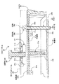
35 to 37 are diagrams for explaining the data center 1 according to the related art. As shown in FIG. 35 and FIG. 36, a
図36に示すように、フロアパネル3は、コンクリートの基礎床面5上から立設する支持脚7により所定の高さで水平に支持されて、データセンター1の部屋の床面を形成するように並べて敷設されることにより、このフロアパネル3と、その下方の基礎床面5との間の空間に配管や配線を通すことができるようになっていた。
As shown in FIG. 36, the
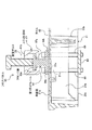
また、データセンター1内における、フロアパネル3が敷設されていない場所には、基礎床面5上から立設する架台2が配置され、サーバーを各段の棚の上に搭載した複数のサーバーラック10が、互いに隣合って並んで架台2の上に載置されていた(例えば、特許文献2参照)。
Further, in the data center 1 where the
架台2は、複数のL型の鋼材(アングル材4)と、板状の鋼板(上板部材6)を組み合わせて、フリーアクセスフロア12の床面(フロアパネル3の上面)と同じ高さになると共に、サーバーラック10のサイズ(幅と奥行き)に合わせるように製作されていた。また、架台2の脚部は、基礎床面5上にアンカーボルト11により固定されていた。
The
また、サーバーラック10の底面を形成する底板部10a、及び架台2の上面を形成する上板部材6にそれぞれ形成された貫通孔に、固定ボルト8のオネジ部が挿通されていた。
In addition, the male screw portion of the
そして、固定ボルト8の頭部の下面が、サーバーラック10の底板部10aの上面に係合すると共に、固定ボルト8のオネジ部の先端部に締結された固定ナット9の上面(図36中上側の面)が、上板部材6の下面に係合していた。
The lower surface of the head of the
このように、サーバーラック10が、架台2の上面から上方に浮き上がって転倒することがないように、サーバーラック10と架台2は、固定ボルト8及び固定ナット9を用いて連結されていた。
Thus, the
サーバーラック10を架台2の上に配置することにより、サーバーラック10の荷重をフロアパネル3が受けるのではなく、その荷重を架台2を介して基礎床面5に直接作用させることができるため、フロアパネル3の上面に載置する場合よりも、サーバーラック10の荷重に対する耐荷重性を向上することができていた。
By placing the
さらに、サーバーラック10を、架台2の上に配置することにより、フロアパネル3の上に配置する場合よりも、サーバーラック10が地震発生時等に転倒することを防止することができると共に、サーバーラック10の水平度を向上することができていた。
Furthermore, by arranging the
しかしながら、従来技術のデータセンター1においては、サーバーラック10のサイズ(幅と奥行き)が製品ごとに異なるため、サーバーラック10の転倒を防止するためにサーバーラック10の底板部10aに設けられた、架台2との連結用の貫通孔の位置も製品ごとに異なっていた。
However, in the data center 1 of the prior art, since the size (width and depth) of the
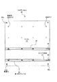
そのため、図37に示すように、サーバーラック10の底板部10aに設けられる貫通孔の水平方向の位置を想定して、予め架台2の上板部材6にサーバーラック10と連結するための貫通孔2aを多数形成する必要があった。
Therefore, as shown in FIG. 37, assuming a horizontal position of the through hole provided in the
また、サーバーラック10の底板部10aに設けられる貫通孔の水平方向の位置が、アングル材4により支持された上板部材6の周辺部に配置されると想定される場合には、上板部材6及びアングル材4を共に貫通するように、サーバーラック10と連結するための貫通孔2aを予め多数形成する必要があった。
Further, when it is assumed that the horizontal position of the through hole provided in the
また、サーバーラック10の底板部10aに設けられる貫通孔が、予め想定していない位置に形成されていた場合には、その都度、架台2の上板部材6、又は上板部材6とアングル材4の両方にサーバーラック10と連結するための貫通孔2aを形成する必要があった。
Moreover, when the through-hole provided in the
このように、様々な種類のサーバーラック10に応じて、架台2に貫通孔2aを形成する必要があるため、サーバーラック10の設置工事にかかる費用が高額になると共に、施工効率が低減するという問題があった。
Thus, since it is necessary to form the through-
そこで本発明は、上記問題点に鑑みて、サーバーラックの設置工事にかかる費用が高額になることを防止すると共に、施工効率が低減することを防止することができる二重床部材を提供することを課題とするものである。 Therefore, in view of the above problems, the present invention provides a double floor member that can prevent an increase in the cost for server rack installation work and prevent a reduction in construction efficiency. Is an issue.
上記課題を解決するために、本発明による二重床部材は、
略正方形に形成された平坦な上面を有し、基礎床面から所定の高さ位置に水平に支持されて、前記上面が基礎床面から所定の高さ位置に水平な床面を形成するように並べて配置されるフロアパネルと、
前記フロアパネルの前記上面と接触し、前記上面に沿って水平方向に伸びるように配置されると共に、前記上面に固定された第1ガイドレールと、
前記第1ガイドレールの長さ方向に沿って移動可能であると共に、前記第1ガイドレールから上方に離脱することがないように、前記第1ガイドレールに係合された第1連結部材とを備え、
前記第1連結部材は、前記第1ガイドレール及び前記第1連結部材と前記フロアパネルの前記上面に載置された筐体が直接接触することなく、前記筐体と固定ボルトを介して連結されるように構成された
ことを特徴とするものである。
In order to solve the above problems, the double floor member according to the present invention is:
It has a flat upper surface formed in a substantially square shape and is horizontally supported at a predetermined height position from the foundation floor surface so that the upper surface forms a horizontal floor surface at a predetermined height position from the foundation floor surface. Floor panels arranged side by side,
A first guide rail disposed in contact with the upper surface of the floor panel and extending horizontally along the upper surface, and fixed to the upper surface;
A first connecting member that is movable along the length direction of the first guide rail and that is engaged with the first guide rail so as not to be detached upward from the first guide rail; Prepared ,
The first connecting member is connected to the housing via a fixing bolt without direct contact between the first guide rail and the first connecting member and the housing placed on the upper surface of the floor panel. It is comprised so that it might be comprised .
また、本発明による二重床部材は、
略正方形に形成された平坦な上面を有し、基礎床面から所定の高さ位置に水平に支持されて、前記上面が基礎床面から所定の高さ位置に水平な床面を形成するように並べて配置されるフロアパネルと、
前記フロアパネルの前記上面と接触し、前記上面に沿って水平方向に伸びるように配置されると共に、前記上面に固定された第1ガイドレールと、
前記第1ガイドレールの長さ方向に沿って移動可能であると共に、前記第1ガイドレールから上方に離脱することがないように、前記第1ガイドレールに係合された第1連結部材とを備え、
前記第1ガイドレールの間を架け渡すように配置されると共に、前記第1ガイドレールに係合された前記第1連結部材それぞれに連結された第2ガイドレールと、
前記第2ガイドレールの長さ方向に沿って移動可能であると共に、前記第2ガイドレールから上方に離脱することがないように、前記第2ガイドレールに係合された第2連結部材とを備え、
前記第2連結部材は、前記第2ガイドレール及び前記第2連結部材と前記フロアパネルの前記上面に載置された筐体が直接接触することなく、前記筐体と固定ボルトを介して連結されるように構成された
ことを特徴とするものである。
The double floor member according to the present invention is
It has a flat upper surface formed in a substantially square shape and is horizontally supported at a predetermined height position from the foundation floor surface so that the upper surface forms a horizontal floor surface at a predetermined height position from the foundation floor surface. Floor panels arranged side by side,
A first guide rail disposed in contact with the upper surface of the floor panel and extending horizontally along the upper surface, and fixed to the upper surface;
A first connecting member that is movable along the length direction of the first guide rail and that is engaged with the first guide rail so as not to be detached upward from the first guide rail; Prepared,
A second guide rail that is disposed so as to bridge between the first guide rails and that is coupled to each of the first coupling members that are engaged with the first guide rail;
A second connecting member that is movable along the length direction of the second guide rail and that is engaged with the second guide rail so as not to be detached upward from the second guide rail. Prepared ,
The second connecting member is connected to the housing via a fixing bolt without direct contact between the second guide rail and the second connecting member and the housing placed on the upper surface of the floor panel. It is comprised so that it might be comprised .
また、本発明による二重床部材は、
略正方形に形成された平坦な上面を有し、基礎床面から所定の高さ位置に水平に支持されて、前記上面が基礎床面から所定の高さ位置に水平な床面を形成するように並べて配置されるフロアパネルと、
前記フロアパネルの前記上面に沿って水平方向に伸びると共に、前記上面から床下方向に凹むように、前記上面に形成された溝レールと、
前記溝レールの内側に配置され、その長さ方向に沿って移動可能であると共に、前記溝レールから上方に離脱することがないように、前記溝レールに係合された第1連結部材とを備え、
前記第1連結部材は、前記第1連結部材と前記フロアパネルの前記上面に載置された筐体が直接接触することなく、前記筐体と固定ボルトを介して連結されるように構成された
ことを特徴とするものである。
The double floor member according to the present invention is
It has a flat upper surface formed in a substantially square shape and is horizontally supported at a predetermined height position from the foundation floor surface so that the upper surface forms a horizontal floor surface at a predetermined height position from the foundation floor surface. Floor panels arranged side by side,
A groove rail formed on the upper surface so as to extend horizontally along the upper surface of the floor panel and to be recessed from the upper surface in the lower floor direction,
A first connecting member disposed on the inner side of the groove rail and movable along the length direction of the groove rail and engaged with the groove rail so as not to be detached upward from the groove rail; Prepared ,
The first connecting member is configured such that the first connecting member and the casing placed on the upper surface of the floor panel are connected to the casing via a fixing bolt without directly contacting the first connecting member. It is characterized by this.
また、本発明による二重床部材は、
略正方形に形成された平坦な上面を有し、基礎床面から所定の高さ位置に水平に支持されて、前記上面が基礎床面から所定の高さ位置に水平な床面を形成するように並べて配置されるフロアパネルと、
前記フロアパネルの前記上面に沿って水平方向に伸びると共に、前記上面から床下方向に凹むように、前記上面に形成された溝レールと、
前記溝レールの内側に配置され、その長さ方向に沿って移動可能であると共に、前記溝レールから上方に離脱することがないように、前記溝レールに係合された第1連結部材とを備え、
前記溝レールの間を架け渡すように配置されると共に、前記溝レールに係合された前記第1連結部材それぞれに連結された第2ガイドレールと、
前記第2ガイドレールの長さ方向に沿って移動可能であると共に、前記第2ガイドレールから上方に離脱することがないように前記第2ガイドレールに係合された第2連結部材とを備え、
前記第2連結部材は、前記第2ガイドレール及び前記第2連結部材と前記フロアパネルの前記上面に載置された筐体が直接接触することなく、前記筐体と固定ボルトを介して連結されるように構成された
ことを特徴とするものである。
The double floor member according to the present invention is
It has a flat upper surface formed in a substantially square shape and is horizontally supported at a predetermined height position from the foundation floor surface so that the upper surface forms a horizontal floor surface at a predetermined height position from the foundation floor surface. Floor panels arranged side by side,
A groove rail formed on the upper surface so as to extend horizontally along the upper surface of the floor panel and to be recessed from the upper surface in the lower floor direction,
A first connecting member disposed on the inner side of the groove rail and movable along the length direction of the groove rail and engaged with the groove rail so as not to be detached upward from the groove rail; Prepared,
A second guide rail which is arranged so as to bridge between the groove rails and which is connected to each of the first connecting members engaged with the groove rail;
A second connecting member that is movable along a length direction of the second guide rail and that is engaged with the second guide rail so as not to be detached upward from the second guide rail. ,
The second connecting member is connected to the housing via a fixing bolt without direct contact between the second guide rail and the second connecting member and the housing placed on the upper surface of the floor panel. It is comprised so that it might be comprised .
また、本発明による二重床部材は、
前記第1連結部材には、固定ボルトを介して連結できるように筐体連結用の孔が形成されたことを特徴とするものである。The double floor member according to the present invention is
The first connecting member is formed with a housing connecting hole so as to be connected via a fixing bolt.
また、本発明による二重床部材は、
前記第2連結部材には、固定ボルトを介して連結できるように筐体連結用の孔が形成されたことを特徴とするものである。The double floor member according to the present invention is
The second connecting member is formed with a housing connecting hole so as to be connected via a fixing bolt.
このような本発明の二重床部材によれば、
略正方形に形成された平坦な上面を有し、基礎床面から所定の高さ位置に水平に支持されて、前記上面が基礎床面から所定の高さ位置に水平な床面を形成するように並べて配置されるフロアパネルと、
前記フロアパネルの前記上面と接触し、前記上面に沿って水平方向に伸びるように配置されると共に、前記上面に固定された第1ガイドレールと、
前記第1ガイドレールの長さ方向に沿って移動可能であると共に、前記第1ガイドレールから上方に離脱することがないように、前記第1ガイドレールに係合された第1連結部材とを備え、
前記第1連結部材は、前記第1ガイドレール及び前記第1連結部材と前記フロアパネルの前記上面に載置された筐体が直接接触することなく、前記筐体と固定ボルトを介して連結されるように構成されたことにより、
サーバーラックの設置工事にかかる費用が高額になることを防止すると共に、施工効率が低減することを防止することができる。
According to such a double floor member of the present invention,
It has a flat upper surface formed in a substantially square shape and is horizontally supported at a predetermined height position from the foundation floor surface so that the upper surface forms a horizontal floor surface at a predetermined height position from the foundation floor surface. Floor panels arranged side by side,
A first guide rail disposed in contact with the upper surface of the floor panel and extending horizontally along the upper surface, and fixed to the upper surface;
A first connecting member that is movable along the length direction of the first guide rail and that is engaged with the first guide rail so as not to be detached upward from the first guide rail; Prepared ,
The first connecting member is connected to the housing via a fixing bolt without direct contact between the first guide rail and the first connecting member and the housing placed on the upper surface of the floor panel. By being configured to
It is possible to prevent the cost for installing the server rack from becoming high and prevent the construction efficiency from being reduced.
以下、本発明に係る二重床部材を実施するための形態について、図面に基づいて具体的に説明する。
図1から図13は、本発明の第1の実施の形態に係るフロアパネル20(二重床部材)について説明するために参照する図である。Hereinafter, the form for implementing the double floor member concerning the present invention is explained concretely based on a drawing.
FIGS. 1 to 13 are views referred to for describing a floor panel 20 (double floor member) according to the first embodiment of the present invention.
本実施の形態に係るフロアパネル20は、図1から図4に示すように、主にパネル本体部21と、その上面に貼り付けられた一枚のタイル22と、タイル22の上面に固定され
た第1ガイドレール24、及び第1ガイドレール24内にその長さ方向に移動可能に配置されたスライド部材27(第1連結部材)等を備えて構成されている。As shown in FIGS. 1 to 4, the
パネル本体部21は、その材質にアルミニウム合金を用いたダイカスト製品であって、その上面を形成する平板部21aと、この平板部21aの裏面側に一体的に形成された複数のリブ21bを備えて構成されている(図2参照)。
The panel
パネル本体部21の複数のリブ21bのそれぞれは、平板部21aの裏面側から床下方向(図5,7中下側方向)に突出すると共に、平板部21aの水平面に沿って縦横両方向(図2中上下方向及び左右方向)に長さが伸びるように格子状に形成されている。パネル本体部21は、このような複数のリブ21bが形成されていることにより、その強度が向上するようになっている。
Each of the plurality of
また、パネル本体部21の平板部21aにおける、その裏面側にリブ21bの形成されていない位置には、平板部21aの板厚方向(図3中上下方向)に貫通する16個の貫通孔21cが、所定の間隔を空けて並んで形成されている(図1,2参照)。
Further, in the
また、パネル本体部21の平板部21aの上面側には、塩化ビニル系のPタイルや、HPL(ハイプレッシャーラミネート)タイル等のタイル22が貼り付けられ、パネル本体部21の平板部21aにタイル22が貼り付けられた状態で、フロアパネル20の各辺を形成するそれぞれの外周部分が共に機械切削加工されている。このため、フロアパネル20の各辺の外周部分は、その寸法精度が高く(例えば、±0、1mm以下)形成されている。
Further, a
また、タイル22における、パネル本体部21の平板部21aに形成された貫通孔21cに対応する位置には、その貫通孔21cに連通するように、タイル22の板厚方向(図6中上下方向)に貫通する貫通孔22aが16個形成されている(図1参照)。
Further, in the
また、第1ガイドレール24は、その材質に鋼材等を用いて、その長さ方向に垂直な断面形状がC字型(図8参照)になるように形成されており、タイル22の上面に、C字型の開口部が上方(同図中上側)に向く状態(C字を反時計回り方向に90度回転させたような状態)で、その開口部と反対側の底板部24aが接触して固定されている。
Further, the
また、図1に示すように、タイル22の上面には、2本の第1ガイドレール24が、互いに長さ方向が平行になるように、タイル22の上面における同図中略右側端部から略左側端部に渡って、同図中左右方向に伸びるように配置されている。
As shown in FIG. 1, two
また、第1ガイドレール24における、タイル22の上面に接触する底板部24a(図6,8参照)には、その板厚方向に貫通する貫通孔24bが形成されており、第1ガイドレール24は、その貫通孔24bが、上記パネル本体部21の貫通孔21c、及びタイル22の貫通孔22aに連通するように配置されている。
Further, in the
そして、図6に示すように、ボルト29は、その頭部29aの下面が第1ガイドレール24の底板部24aの内周側の上面に接触して係合すると共に、そのオネジ部29bが第1ガイドレール24の貫通孔24b、タイル22の貫通孔22a、及びパネル本体部21の貫通孔21cを挿通している。
As shown in FIG. 6, the
また、パネル本体部21の複数のリブ21bの内、平板部21aの裏面側から床下方向(図6中下側方向)に突出する長さ寸法が最も大きいリブ21bの先端部に、その上面が接触するように平板状の板部材25が配置され、その板部材25には、板厚方向(図6中上下方向)に貫通するメネジ孔25aが形成されている。
Further, among the plurality of
そして、第1ガイドレール24の貫通孔24b、タイル22の貫通孔22a、及びパネル本体部21の貫通孔21cを挿通して、図6中下方に突出しているボルト29のオネジ部29bの先端部は、板部材25のメネジ孔25aにネジ締結されている。
And the front-end | tip part of the
このように、ボルト29の頭部29aの下面が、第1ガイドレール24の底板部24aの上面に係合すると共に、ボルト29のオネジ部29bの先端部にネジ締結された板部材25の上面が、パネル本体部21のリブ21bの下面に係合することにより、第1ガイドレール24は、タイル22の上面から上方に浮き上がることがないようにタイル22に固定されている。
In this way, the lower surface of the
また、スライド部材27は、その材質に鋼材等を用いて、その長さ方向に垂直な断面形状がU字型状(図8参照)になるように形成されており、第1ガイドレール24の内側に、U字型の開口部が同図中下側に向く逆U字型の状態で配置されている。
Further, the
また、スライド部材27は、そのU字型の開口部側とは反対側の上側板部27aの下面27b(図6,8参照)の高さ位置が、ボルト29の頭部29aの上面の高さ位置よりも高くなるように形成されている。
The
さらに、スライド部材27は、そのU字型の開口部の幅(図8中左右方向の長さ寸法)が、ボルト29の頭部29aの直径(図8中左右方向の長さ寸法)よりも大きくなるように形成されている。
Furthermore, the width of the U-shaped opening of the slide member 27 (length dimension in the left-right direction in FIG. 8) is larger than the diameter of the
そのため、スライド部材27を第1ガイドレール24の長さ方向に沿って移動させた場合に、スライド部材27がボルト29の頭部29aに接触することはなく、第1ガイドレール24の図1中右側の端部から同図中左側の端部まで、スライド部材27を自由に移動させることができる。
Therefore, when the
また、スライド部材27の上側板部27aの幅の寸法(図8中左右方向の長さ寸法)は、第1ガイドレール24の上方に開口する開口幅の寸法(図8中左右方向の長さ寸法)よりも大きく形成されている。
Further, the dimension of the width of the
そのため、スライド部材27は、図8中上方への移動が第1ガイドレール24に係合することにより制限され、スライド部材27が同図中上方に引っ張られた場合でも、第1ガイドレール24の開口部を通って、スライド部材27が第1ガイドレール24から抜け出す(離脱する)ことがないように形成されている。
Therefore, the
また、スライド部材27の上側板部27aには、その板厚方向(図8中上下方向)に貫通するメネジ孔27cが、スライド部材27の長さ方向(図6中左右方向)に隣合って3つ形成されている。
Further, in the
そして、スライド部材27の上側板部27aの3つのメネジ孔27cは、図8に示すように、第1ガイドレール24の同図中上方に開口する開口部を通って挿入される固定ボルト26のオネジ部26bにネジ締結できるようになっている。
Then, as shown in FIG. 8, the three female screw holes 27c of the
フロアパネル20の上面には、図9及び図10に示すように、その底板部100bに脚部100aが取り付けられたサーバーラック100(筐体)が載置されている。また、フロアパネル20の四隅部は、それぞれ支持脚109により支持されている。
On the upper surface of the
フロアパネル20の四隅部には、図1中紙面に対して垂直方向に貫通する貫通孔20a(図1,2参照)と、その貫通孔20aを囲むように、フロアパネル20の上面側から床下方向(図9中下方向)に少し凹んだ段差面がそれぞれ形成されている。
At the four corners of the
そして、フロアパネル20の上面側から貫通孔20aに挿通されたボルト(不図示)の頭部が、その段差面に係合すると共に、そのボルトのオネジ部が支持脚109(図9参照)の支持面側に形成されたメネジ孔(不図示)にネジ締結されることにより、フロアパネル20の四隅部は支持脚109にそれぞれ固定されている。
And the head part of the bolt (not shown) inserted through the through
また、支持脚109はサーバーラック100の荷重に耐えることができるような耐荷重性を有しており、支持脚109の脚部は、図9及び図10に示すように、アンカーボルト115により基礎床面5上に固定されている。
Further, the
また、サーバーラック100の底板部100b(図11参照)には、その板厚方向(図11中上下方向)に貫通する貫通孔100cが形成されている。
Further, the
ところで、図9に示されるフロアパネル20には、必要な数の第1ガイドレール24が固定されている。そのため、図9においては、図1のように2本の第1ガイドレール24が固定されているフロアパネル20と、1本の第1ガイドレール24のみが固定されているフロアパネル20が示されている。
Incidentally, a required number of
図11に示すように、固定ボルト26の頭部26aの下面が、サーバーラック100の底板部100bの上面に接触して係合すると共に、固定ボルト26のオネジ部26bの先端部が、サーバーラック100の貫通孔100c、及び第1ガイドレール24の開口部を挿通して、スライド部材27の上側板部27aに形成されたメネジ孔27cにネジ締結している(図8参照)。
As shown in FIG. 11, the lower surface of the head 26a of the fixing
このように、固定ボルト26の頭部26aの下面が、サーバーラック100の底板部100bの上面に係合すると共に、固定ボルト26のオネジ部26bが、第1ガイドレール24内から上方に抜け出さないように設けられたスライド部材27にネジ締結されているため、サーバーラック100は、フロアパネル20の上面から上方に浮き上がって転倒することがないように、固定ボルト26を介してフロアパネル20に連結されている。
As described above, the lower surface of the head 26 a of the fixing
また、フロアパネル20に連結するサーバーラック100の貫通孔100cに対して、スライド部材27の図1中左右方向の位置が一致していない場合には、スライド部材27を第1ガイドレール24の長さ方向に沿って移動させることにより、サーバーラック100の貫通孔100cの位置に、スライド部材27の位置を合わせることができる。
Further, when the position of the
また、図1においては、サーバーラック100とフロアパネル20を連結する固定ボルト26は、スライド部材27に形成された3つのメネジ孔27c(図6参照)の内、スライド部材27の同図中の中央部位置のメネジ孔27cにネジ締結されている。
Further, in FIG. 1, the fixing
しかしながら、スライド部材27を第1ガイドレール24に沿って移動させて、第1ガイドレール24の図1中右側端部の位置において、固定ボルト26をスライド部材27の同図中の中央部位置のメネジ孔27cにネジ締結させることにより、サーバーラック100とフロアパネル20とを固定ボルト26を介して連結しようとすると、スライド部材27の長さ方向の図1中右側端部が、第1ガイドレール24の長さ方向外側に突出するおそれがある。
However, the
そのため、例えば、第1ガイドレール24の長さ方向両端部に、スライド部材27が第1ガイドレール24の長さ方向外側に突出することを防止するストッパーを設けた場合には、第1ガイドレール24の図1中右側端部の位置に、スライド部材27の同図中の中央部位置のメネジ孔27cを合わせることができなくなる。
Therefore, for example, when stoppers that prevent the
このような場合には、図12に示すように、固定ボルト26を、スライド部材27に形成された3つのメネジ孔27c(図6参照)の内、同図中最も右側のメネジ孔27cにネジ締結することにより、スライド部材27の長さ方向の同図中右側端部が第1ガイドレール24の長さ方向外側に突出しないようにすることができる。
In such a case, as shown in FIG. 12, the fixing
すなわち、第1ガイドレール24の長さ方向両端部に上記のようなストッパーを設けた場合でも、第1ガイドレール24の図1中右側端部の位置に、スライド部材27の同図中最も右側のメネジ孔27cを合わせることにより、サーバーラック100とフロアパネル20とを固定ボルト26を介して連結することができる。
That is, even when the stoppers as described above are provided at both ends in the longitudinal direction of the
スライド部材27を第1ガイドレール24に沿って移動させて、第1ガイドレール24の図1中左側端部の位置において、サーバーラック100とフロアパネル20とを固定ボルト26を介して連結しようとする場合も同様である。
The
すなわち、固定ボルト26を、スライド部材27に形成された3つのメネジ孔27c(図6参照)の内、図1中最も左側のメネジ孔27cにネジ締結することにより、スライド部材27の長さ方向の図1中左側端部が第1ガイドレール24の長さ方向外側に突出しないようにすることができる。
That is, the fixing
また、フロアパネル20に連結するサーバーラック100の貫通孔100cに対して、スライド部材27の図1中上下方向の位置が一致していない場合には、第1ガイドレール24のタイル22の上面における固定位置を、貫通孔22aが形成された他の位置に変更することにより、スライド部材27の図1中上下方向の位置を変更することができる。
Further, in the case where the position of the
例えば、図1において、2本の第1ガイドレール24は、タイル22の上面における同図中下側2列の図中左右方向に並んで形成された貫通孔22aの位置に固定されているが、スライド部材27の図中上下方向の位置を、サーバーラック100の貫通孔100cの位置に合わせるために、図13に示すように、タイル22の上面における同図中上下方向の中央部の2列の図中左右方向に並んで形成された貫通孔22aの位置に、2本の第1ガイドレール24を固定する位置を変更することができる。
For example, in FIG. 1, the two
このように、サーバーラック100のサイズ(幅と奥行き)が製品ごとに異なることにより、サーバーラック100の貫通孔100cの位置が製品ごとに異なっている場合でも、第1ガイドレール24の固定位置を変更したり、スライド部材27を第1ガイドレール24の長さ方向に沿って移動させることにより、固定ボルト26とネジ締結されるスライド部材27の水平方向の位置を、サーバーラック100の貫通孔100cの水平方向の位置に合わせることができる。
As described above, the size (width and depth) of the
したがって、サーバーラック100の設置工事に、本実施の形態に係るフロアパネル20を用いれば、サーバーラック100の製品ごとに異なる貫通孔100cの水平方向の位置を想定して、サーバーラック100を固定するための貫通孔をフロアパネル20に予め多数形成する必要がなくなる。
Therefore, if the
また、サーバーラック100の設置工事に、本実施の形態に係るフロアパネル20を用いれば、サーバーラック100の製品ごとに異なる貫通孔100cの水平方向の位置が、予め想定できない位置であった場合に、その都度、サーバーラック100を固定するための貫通孔をフロアパネル20に形成する必要がなくなる。
If the
したがって、サーバーラック100の設置工事に、本実施の形態に係るフロアパネル20を用いれば、サーバーラック100の設置工事にかかる費用が高額になることを防止すると共に、施工効率が低減することを防止することができる。
Therefore, if the
図14から図26は、本発明の第2の実施の形態に係るフロアパネル30(二重床部材)について説明するために参照する図である。 FIGS. 14 to 26 are views referred to for describing a floor panel 30 (double floor member) according to the second embodiment of the present invention.
本実施の形態に係るフロアパネル30は、図14に示すように、第1ガイドレール24、及びスライド部材27の他に、第2ガイドレール34及びスライド部材37(第2連結部材)も備える点において、前記第1の実施の形態に係るフロアパネル20と異なるものである。その他の構成は、前記第1の実施の形態に係るフロアパネル20と同様である。
As shown in FIG. 14, the
すなわち、前記第1の実施の形態に係るフロアパネル20においては、図1に示すように、同図中左右方向に伸びる2本の第1ガイドレール24がタイル22の上面に固定され、それらの第1ガイドレール24の長さ方向に沿ってスライド部材27を移動させることにより、スライド部材27の水平方向の位置をサーバーラック100の貫通孔100cの水平方向の位置に合わせることができていた。
That is, in the
一方、本実施の形態に係るフロアパネル30においては、図14に示すように、同図中左右方向に伸びる2本の第1ガイドレール24が、タイル22の上面に固定されているだけでなく、2本の第1ガイドレール24に直交する(第1ガイドレール24の間を架け渡す)ように、同図中上下方向に伸びる2本の第2ガイドレール34の長さ方向両端部が、第1ガイドレール24の上面にそれぞれ固定されている(図16参照)。
On the other hand, in the
そして、第1ガイドレール24の長さ方向に沿って、スライド部材27を移動させることにより、第2ガイドレール34を図14中左右方向に移動させると共に、第2ガイドレール34の長さ方向に沿って、スライド部材37を移動させることができる。
Then, by moving the
このため、スライド部材37を第1ガイドレール24、及び第2ガイドレール34のそれぞれの長さ方向に沿って、図14中上下左右方向に移動させることにより、スライド部材37の水平方向の位置を、サーバーラック100の貫通孔100cの水平方向の位置に合わせることができる
For this reason, the horizontal position of the
第2ガイドレール34の長さ方向両端部における、第1ガイドレール24の上面に接触する底板部34a(図20参照)には、その板厚方向に貫通する貫通孔34b(図18参照)が形成されており、第2ガイドレール34は、その貫通孔34bがスライド部材27の3つのメネジ孔27cの内、図18中左右方向中央部の位置のメネジ孔27cに連通するように配置されている。
The
そして、図20に示すように、ボルト39の頭部39aの下面が、第2ガイドレール34の底板部34aの上面に接触して係合すると共に、ボルト39のオネジ部がスライド部材27のメネジ孔27cにネジ締結されることにより、第2ガイドレール34の長さ方向両端部は、第1ガイドレール24に沿って移動可能なスライド部材27に連結されている。
As shown in FIG. 20, the lower surface of the
また、スライド部材37は、その材質に鋼材等を用いて、その垂直断面形状がU字型状(図18参照)になるように形成されており、第2ガイドレール34の内側に、そのU字型の開口部が図18中下側に向く逆U字型の状態で配置されている。
The
また、スライド部材37は、そのU字型の開口部側とは反対側の上側板部37aの下面37b(図18,20参照)の高さ位置が、ボルト39の頭部39aの上面の高さ位置よりも高くなるように形成されている。
The
さらに、スライド部材37は、そのU字型の開口部の幅(図18中左右方向の長さ寸法)が、ボルト39の頭部39aの直径(図18中左右方向の長さ寸法)よりも大きくなるように形成されている。
Furthermore, the width of the U-shaped opening of the slide member 37 (length dimension in the left-right direction in FIG. 18) is larger than the diameter of the
そのため、スライド部材37を第2ガイドレール34の長さ方向に沿って移動させた場合に、スライド部材37がボルト39の頭部39aに接触することはなく、第2ガイドレール34の図14中上側端部から下側端部まで、スライド部材37を自由に移動させることができる。
Therefore, when the
また、スライド部材37の上側板部37aの幅の寸法(図18中左右方向の長さ寸法)は、第2ガイドレール34の上方に開口する開口幅の寸法(図18中左右方向の長さ寸法)よりも大きく形成されている。
Further, the dimension of the width of the
そのため、スライド部材37は、図18中上方への移動が第2ガイドレール34に係合することにより制限され、スライド部材37が同図中上方に引っ張られた場合でも、第2ガイドレール34の開口部を通って、スライド部材37が第2ガイドレール34から抜け出す(離脱する)ことがないように形成されている。
Therefore, the upward movement of the
また、スライド部材37の上側板部37aには、その板厚方向(図20中上下方向)に貫通するメネジ孔37cが、スライド部材37の長さ方向(図20中左右方向)に並んで3つ形成されている。
Further, in the
そして、スライド部材37の上側板部37aの3つのメネジ孔37cは、図18に示すように、第2ガイドレール34の同図中上方に開口する開口部を通って挿入される固定ボルト26のオネジ部26bにネジ締結することができるようにそれぞれ形成されている。
Then, the three female screw holes 37c of the
フロアパネル30の上面には、図21及び図22に示すように、底板部100bに脚部100aが取り付けられたサーバーラック100が載置されている。また、サーバーラック100の底板部100b(図23参照)には、その板厚方向(図23中上下方向)に貫通する貫通孔100cが形成されている。
On the upper surface of the
また、前記第1の実施の形態に係るフロアパネル20と同様に、フロアパネル30の四隅部に形成された貫通孔30a(図14参照)にボルト(不図示)が挿通され、そのボルトの頭部がフロアパネル30の上面側に形成された段差面に係合すると共に、そのボルトのオネジ部が支持脚109(図21参照)の支持面側に形成されたメネジ孔(不図示)にネジ締結されることにより、フロアパネル30の四隅部は支持脚109にそれぞれ固定されている。
Similarly to the
また、支持脚109は、図21及び図22に示すように、アンカーボルト115により基礎床面5上に固定されている。
Moreover, the
ところで、図21に示されるフロアパネル30には、必要な数の第2ガイドレール34が固定されている。そのため、図21においては、図14のように2本の第2ガイドレール34が固定されているフロアパネル30と、1本の第2ガイドレール34のみが固定されているフロアパネル30が示されている。
Incidentally, a required number of
そして、図23に示すように、固定ボルト26の頭部26aの下面が、サーバーラック100の底板部100bの上面に接触して係合すると共に、固定ボルト26のオネジ部26bの先端が、サーバーラック100の底板部100bの貫通孔100c、及び第2ガイドレール34の開口部を挿通して、スライド部材37の上側板部37aに形成されたメネジ孔37cにネジ締結している。
As shown in FIG. 23, the lower surface of the head portion 26a of the fixing
このように、固定ボルト26の頭部26aの下面が、サーバーラック100の底板部100bの上面に係合すると共に、固定ボルト26のオネジ部26bが、第2ガイドレール34内から上方に抜け出さないように形成されたスライド部材37にネジ締結されているため、サーバーラック100は、フロアパネル30の上面から浮き上がって転倒することがないように、固定ボルト26を介してフロアパネル30に連結されている。
In this way, the lower surface of the head 26a of the fixing
したがって、連結するサーバーラック100の貫通孔100cに対して、スライド部材37の図14中左右上下方向の位置が一致していない場合には、スライド部材27を第1ガイドレール24の長さ方向に沿って移動させることにより、第2ガイドレール34を図14中左右方向に移動させると共に、スライド部材37を第2ガイドレール34の長さ方向に沿って移動させることにより、スライド部材37の位置を、連結するサーバーラック100の貫通孔100cの位置に合わせることができる。
Accordingly, when the position of the
すなわち、フロアパネル30は、第1ガイドレール24,及び第2ガイドレール34のそれぞれの長さ方向に沿って、スライド部材37を移動できるように構成されているため、2本の第1ガイドレール24の間の範囲に、サーバーラック100の底板部100bの貫通孔100cの水平方向の位置が配置される場合には、第1ガイドレール24,及び第2ガイドレール34のそれぞれの長さ方向にスライド部材37を移動させることにより、貫通孔100cの水平方向の位置に、スライド部材37の水平方向の位置を合わせることができる。
That is, since the
また、図14においては、サーバーラック100とフロアパネル30を連結する固定ボルト26は、スライド部材37に形成された3つのメネジ孔37cの内、同図中の中央部位置のメネジ孔37cにネジ締結されている(図20,24参照)。
Further, in FIG. 14, the fixing
しかしながら、スライド部材37を第2ガイドレール34の長さ方向に沿って移動させて、第2ガイドレール34の図14中下側端部の位置において、固定ボルト26を同図中の中央部位置のメネジ孔37cにネジ締結させることにより、サーバーラック100とフロアパネル30とを固定ボルト26を介して連結しようとすると、スライド部材37の長さ方向の図14中下側端部が、第2ガイドレール34の長さ方向外側に突出するおそれがある。
However, the
そのため、例えば、第2ガイドレール34の長さ方向両端部に、スライド部材37が第2ガイドレール34の長さ方向外側に突出することを防止するストッパーを設けた場合には、第2ガイドレール34の図14中下側端部の位置に、スライド部材37の同図中の中央部位置のメネジ孔37cを合わせることができなくなる。
Therefore, for example, when stoppers that prevent the
このような場合には、図24に示すように、固定ボルト26を、スライド部材37に形成された3つのメネジ孔37cの内、同図中最も下側のメネジ孔37c(図20参照)にネジ締結することにより、スライド部材37の長さ方向の同図中下側端部が第2ガイドレール34の長さ方向外側に突出しないようにすることができる。
In such a case, as shown in FIG. 24, the fixing
すなわち、第2ガイドレール34の長さ方向両端部に上記のようなストッパーを設けた場合でも、第2ガイドレール34の図14中下側端部の位置に、スライド部材37の同図中最も下側のメネジ孔37cを合わせることにより、サーバーラック100とフロアパネル30とを固定ボルト26を介して連結することができる。
That is, even when the stoppers as described above are provided at both ends in the length direction of the
スライド部材37を第2ガイドレール34に沿って移動させて、第2ガイドレール34の図14中上側端部の位置において、サーバーラック100とフロアパネル30とを固定ボルト26を介して連結しようとする場合も同様である。
The
すなわち、固定ボルト26を、スライド部材37に形成された3つのメネジ孔27c(図20参照)の内、図14中最も上側のメネジ孔37cにネジ締結することにより、スライド部材37の長さ方向の図14中上側端部が第2ガイドレール34の長さ方向外側に突出しないようにすることができる。
That is, the fixing
また、サーバーラック100の貫通孔100cの図14中上下方向の位置が、2本の第1ガイドレール24の間の範囲内に形成されていない場合には、第1ガイドレール24のタイル22の上面における固定位置を、貫通孔22aが形成された他の位置に変更することにより、スライド部材37の図14中上下方向の移動可能な範囲を変更することができる。
Further, when the position of the through
例えば、図14において、2本の第1ガイドレール24は、タイル22の上面における同図中下側2列に形成された貫通孔22aの位置に固定されているが、図25に示すように、スライド部材37の図14中上下方向の位置を、サーバーラック100の貫通孔100cの位置に合わせるために、タイル22の上面における同図中の中央部の2列に形成された貫通孔22aの位置に、2本の第1ガイドレール24の固定位置を変更することができる。
For example, in FIG. 14, the two
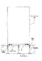
また、図26に示すように、タイル22及びパネル本体部21において、それぞれ互いに間隔を空けて形成された複数の貫通孔22a,21cは、互いに長さ寸法Lの距離だけ同図中上下方向に離れてそれぞれ形成されている。また、フロアパネル30の同図中最も外周側に形成された貫通孔22a,21cから、フロアパネル30の辺部までは、長さ寸法L/2の距離だけ同図中上下方向に離れて形成されている。
In addition, as shown in FIG. 26, in the
そのため、図26に示すように、フロアパネル30の最も外周側に形成された貫通孔22a,21cよりも外周側に、スライド部材37を移動させる場合には、互いに隣合うフロアパネル30,30を跨ぐように、第2ガイドレール34を配置することができる。
Therefore, as shown in FIG. 26, when the
すなわち、互いに隣合うフロアパネル30,30それぞれにおける、最も外周側に形成された貫通孔22a,21cに、第1ガイドレール24をそれぞれ1本ずつ固定すると、互いに隣合うフロアパネル30,30それぞれに固定した第1ガイドレール24,24間の上下方向の距離はL(L/2+L/2の合計)となる。
That is, when the
したがって、互いに隣合うフロアパネル30,30それぞれに固定した第1ガイドレール24,24間の上下方向の距離がL以上になっていないので、フロアパネル30,30間を跨ぐように、第2ガイドレール34の両端部を2本の第1ガイドレール24の上面に連結することにより、スライド部材37をフロアパネル30の周縁部にも移動させることができるようになっている。
Therefore, since the vertical distance between the
このように、サーバーラック100のサイズ(幅と奥行き)が製品ごとに異なることにより、サーバーラック100の貫通孔100cの位置が製品ごとに異なっている場合でも、第1ガイドレール24の固定位置を変更したり、スライド部材27を第1ガイドレール24の長さ方向に沿って移動させたり、スライド部材37を第2ガイドレール34の長さ方向に沿って移動させたりすることにより、固定ボルト26とネジ締結するスライド部材37の水平方向の位置を、サーバーラック100の貫通孔100cの水平方向の位置に合わせることができる。
As described above, the size (width and depth) of the
すなわち、本実施の形態に係るフロアパネル30においては、サーバーラック100の貫通孔100cの水平方向の位置に合わせるように、スライド部材37の位置を移動させることにより、サーバーラック100とフロアパネル30とを水平方向の任意の位置において連結することができる。
That is, in the
したがって、サーバーラック100の設置工事に、本実施の形態に係るフロアパネル30を用いれば、サーバーラック100の製品ごとに異なる貫通孔100cの水平方向の位置を想定して、サーバーラック100を固定するための貫通孔をフロアパネル30に予め多数形成する必要がなくなる。
Therefore, if the
また、サーバーラック100の設置工事に、本実施の形態に係るフロアパネル30を用いれば、サーバーラック100の製品ごとに異なる貫通孔100cの水平方向の位置が、予め想定できない位置であった場合に、その都度、サーバーラック100を固定するための貫通孔をフロアパネル30に形成する必要がなくなる。
If the
したがって、サーバーラック100の設置工事に、本実施の形態に係るフロアパネル30を用いることによっても、前記第1の形態に係るフロアパネル20と同様に、サーバーラック100の設置工事にかかる費用が高額になることを防止すると共に、施工効率が低減することを防止することができる。
Accordingly, even when the
図27は、本発明の第3の実施の形態に係るフロアパネル40(二重床部材)について説明するために参照する図である。 FIG. 27 is a diagram referred to for explaining a floor panel 40 (double floor member) according to the third embodiment of the present invention.
本実施の形態に係るフロアパネル40は、図27に示すように、第1ガイドレール44の長さ寸法が、前記第1の実施の形態に係るフロアパネル20における第1ガイドレール24の長さ寸法よりも短い点において、前記第1の実施の形態に係るフロアパネル20と異なるものである。その他の構成は、前記第1の実施の形態に係るフロアパネル20と同様である。
In the
すなわち、前記第1の実施の形態に係るフロアパネル20においては、図1に示すように、第1ガイドレール24がタイル22の上面における同図中略右側端部から略左側端部に渡って、同図中左右方向に伸びるように配置されていた。
That is, in the
一方、本実施の形態に係るフロアパネル40においては、図27に示すように、第1ガイドレール44は、その両端部が互いに図中左右方向に隣り合う貫通孔22a,21cの位置に配置されるように、フロアパネル20における第1ガイドレール24の略1/3の長さ寸法に形成されている。
On the other hand, in the
このような本実施の形態に係るフロアパネル40によっても、前記第1の実施の形態に係るフロアパネル20と同様の効果を得ることができる。
Also by the
図28は、本発明の第4の実施の形態に係るフロアパネル50(二重床部材)について説明するために参照する図である。 FIG. 28 is a diagram referred to for describing a floor panel 50 (double floor member) according to the fourth embodiment of the present invention.
本実施の形態に係るフロアパネル50は、図28に示すように、パネル本体部51に溝レール51cが形成され、その溝レール51cの長さ方向(図中紙面に対して垂直方向)に沿ってスライド部材27(第1連結部材)が移動できるように構成されている点において、前記第1の実施の形態に係るフロアパネル20と異なるものである。その他の構成は、前記第1の実施の形態に係るフロアパネル20と同様である。
As shown in FIG. 28, in the floor panel 50 according to the present embodiment, a
すなわち、前記第1の実施の形態に係るフロアパネル20においては、図8に示すように、第1ガイドレール24がタイル22の上面に固定され、第1ガイドレール24の内側にスライド部材27を配置し、スライド部材27を第1ガイドレール24の長さ方向に沿って移動させることにより、サーバーラック100の貫通孔100cの位置に、スライド部材27の位置を合わせることができていた(図11参照)。
That is, in the
一方、本実施の形態に係るフロアパネル50においては、図28に示すように、前記第1の実施の形態に係るフロアパネル20における第1ガイドレール24を備えておらず、第1ガイドレール24の代わりに、フロアパネル50の上面から床下方向(図中下側方向)に所定の深さまで凹んだ垂直断面形状が略逆T字型の溝レール51cが形成されている。
On the other hand, in the floor panel 50 according to the present embodiment, as shown in FIG. 28, the
溝レール51cは、第1ガイドレール24と同様に、その内側にスライド部材27を配置して、スライド部材27が溝レール51cの長さ方向(図中紙面に対して垂直方向)に沿って移動することができると共に、スライド部材27が溝レール51cから上方に抜け出す(離脱する)ことがないような形状に形成されている。
Similar to the
また、溝レール51cは、その内側にスライド部材27を配置することができるように、フロアパネル50の上面からタイル22を貫通し、パネル本体部51の平板部51aの所定の深さまで凹むように形成されているため、パネル本体部51の平板部51aの板厚は、前記第1の実施の形態に係るフロアパネル20のパネル本体部21の平板部21aの板厚(図8参照)よりも厚く形成されている。
Further, the
このような本実施の形態に係るフロアパネル50によっても、前記第1の実施の形態に係るフロアパネル20と同様の効果を得ることができる。
Also by the floor panel 50 according to the present embodiment, the same effect as that of the
また、本実施の形態に係るフロアパネル50においては、第1ガイドレール24を備えていないため、前記第1の実施の形態に係るフロアパネル20のように、ボルト29及び板部材25を用いて、第1ガイドレール24をタイル22の上面に固定する作業が必要なくなる(図8参照)。
Moreover, since the floor panel 50 according to the present embodiment does not include the
図29は、本発明の第5の実施の形態に係るフロアパネル55(二重床部材)について説明するために参照する図である。 FIG. 29 is a diagram referred to for describing a floor panel 55 (double floor member) according to the fifth embodiment of the present invention.
本実施の形態に係るフロアパネル55は、図29に示すように、パネル本体部51に溝レール51cが形成され、その溝レール51cの長さ方向(図中紙面に対して垂直方向)に沿ってスライド部材27(第1連結部材)が移動できるように構成されている点において、前記第2の実施の形態に係るフロアパネル30と異なるものである。その他の構成は、前記第2の実施の形態に係るフロアパネル30と同様である。
As shown in FIG. 29, the
すなわち、記第2の実施の形態に係るフロアパネル30が、前記第1の実施の形態に係るフロアパネル20に、第2ガイドレール34及びスライド部材37を設ける構成であったように、本実施の形態に係るフロアパネル55は、前記第4の実施の形態に係るフロアパネル50に、第2ガイドレール34及びスライド部材37(第2連結部材)を設ける構成となっている。
That is, the
このような本実施の形態に係るフロアパネル55によっても、前記第2の実施の形態に係るフロアパネル30と同様の効果を得ることができる。
Also with the
また、本実施の形態に係るフロアパネル50においては、第1ガイドレール24を備えていないため、前記第2の実施の形態に係るフロアパネル30のように、ボルト29及び板部材25を用いて、第1ガイドレール24をタイル22の上面に固定する作業が必要がなくなる(図20参照)。
Further, since the floor panel 50 according to the present embodiment does not include the
図30は、本発明の第6の実施の形態に係るフロアパネル60(二重床部材)について説明するために参照する図である。 FIG. 30 is a view referred to for explaining a floor panel 60 (double floor member) according to the sixth embodiment of the present invention.
本実施の形態に係るフロアパネル60は、図30に示すように、その長さ方向(図中紙面に対して垂直方向)に対して垂直な断面形状が略T字型の第1ガイドレール64がタイル22の上面に固定され、その長さ方向(図中紙面に対して垂直方向)に垂直な断面形状がC字型のスライド部材67が第1ガイドレール64に係合するように構成されている点において、前記第1の実施の形態に係るフロアパネル20と異なるものである。その他の構成は、前記第1の実施の形態に係るフロアパネル20と同様である。
As shown in FIG. 30, the floor panel 60 according to the present embodiment has a
すなわち、前記第1の実施の形態に係るフロアパネル20においては、図8に示すように、第1ガイドレール24は、その長さ方向に垂直な断面形状がC字型(図8参照)になるように形成されており、タイル22の上面に、C字型の開口部が上方(同図中上側)に向く状態で固定されていた。そして、その長さ方向に垂直な断面形状がU字型のスライド部材27が、第1ガイドレール24の内側に、U字型の開口部が同図中下側に向く逆U字型の状態で配置されていた。
That is, in the
一方、本実施の形態に係るフロアパネル60においては、図30に示すように、第1ガイドレール64が、その図中下端部において図中左右方向に張出したフランジ状のフランジ部64bをタイル22の上面に接触させて、略逆T字型の状態でタイル22の上面に固定されている。
On the other hand, in the floor panel 60 according to the present embodiment, as shown in FIG. 30, the
そして、第1ガイドレール64の図中上端部において図中左右方向に張出したフランジ状のフランジ部64aに、スライド部材67の開口部側の下板部67aが係合することにより、垂直断面形状がC字型のスライド部材67は、第1ガイドレール64の長さ方向に沿って移動できると共に、第1ガイドレール64から上方に抜け出す(離脱する)ことがないように形成されている。
Then, the
また、スライド部材67は、その開口部側とは反対側の上板部67bにメネジ孔が形成され、そのメネジ孔に固定ボルト26のオネジ部がネジ締結されるようになっている。
The
また、ボルト69の頭部の下面が、第1ガイドレール64のフランジ部64bの上面に接触して係合すると共に、ボルト69のオネジ部が第1ガイドレール64に形成された貫通孔64c、タイル22の貫通孔22a、及びパネル本体部21の貫通孔21cを挿通して、ボルト69のオネジ部の先端部にネジ締結された板部材65の上面が、パネル本体部21のリブ21bの下面に係合することにより、第1ガイドレール64はタイル22の上面に固定されている(図30参照)。
Further, the lower surface of the head of the
このような本実施の形態に係るフロアパネル60によっても、前記第1の実施の形態に係るフロアパネル20と同様の効果を得ることができる。
Also by the floor panel 60 according to this embodiment, the same effect as that of the
図31は、本発明の第7の実施の形態に係るフロアパネル70(二重床部材)について説明するために参照する図である。 FIG. 31 is a diagram referred to for describing a floor panel 70 (double floor member) according to a seventh embodiment of the present invention.
本実施の形態に係るフロアパネル70は、図31に示すように、第1ガイドレール24をタイル22の上面に固定するボルト79のオネジ部79aが、固定部材74のメネジ部74aにネジ締結されている点において、前記第1の実施の形態に係るフロアパネル20と異なるものである。その他の構成は、前記第1の実施の形態に係るフロアパネル20と同様である。
In the
すなわち、前記第1の実施の形態に係るフロアパネル20においては、図6に示すように、ボルト29のオネジ部29bが第1ガイドレール24の貫通孔24b、タイル22の貫通孔22a、及びパネル本体部21の貫通孔21cを挿通して、ボルト29のオネジ部29bの先端部にネジ締結された板部材25の上面が、パネル本体部21のリブ21bの下面に係合することにより、第1ガイドレール24はタイル22の上面に固定されていた。
That is, in the
一方、本実施の形態に係るフロアパネル70においては、図31に示すように、ボルト79のオネジ部79aが、第1ガイドレール24の貫通孔24b、タイル22の貫通孔22aを挿通して、パネル本体部71の貫通孔71cに同図中下側から嵌合された略円筒状の固定部材74のメネジ部74aにネジ締結されることにより、第1ガイドレール24はタイル22の上面に固定されている。
On the other hand, in the
固定部材74は、図31に示すように、その軸線方向(図中上下方向)に伸びる円筒状の胴体部74bと、胴体部74bの下端部においてその半径方向外側に張出したフランジ状のフランジ部74cを備えている。そして、円筒状の胴体部74bの内周部にメネジ部74aが形成されている。
As shown in FIG. 31, the fixing
また、固定部材74の胴体部74bは、その外周面の外径寸法が、パネル本体部71の貫通孔71cの内径寸法と略同一に形成されている。このため、固定部材74の胴体部74bは、パネル本体部71の貫通孔71cに挿通されると、貫通孔71cに嵌合されるようになっている。
The
また、固定部材74は、図31に示すパネル本体部71の貫通孔71cに、同図中下側からその胴体部74bが挿入されて、ハンマーなどにより同図中下側から打撃されることにより、パネル本体部71の貫通孔71cに挿通されて固定されている。固定部材74は、フランジ部74cがパネル本体部71の平板部71aの下面に接触するまで貫通孔71c内に埋め込まれている。
Further, the fixing
また、本実施の形態に係るフロアパネル70においては、パネル本体部71の平板部71aの板厚は、図中上下方向に長さを有する固定部材74を貫通孔71cに嵌合するために、前記第1の実施の形態に係るフロアパネル20のパネル本体部21の平板部21aの板厚よりも厚く形成されている。
Further, in the
このような本実施の形態に係るフロアパネル70によっても、前記第1の実施の形態に係るフロアパネル20と同様の効果を得ることができる。
The same effects as those of the
また、このような本実施の形態に係るフロアパネル70においては、前記第1の実施の形態に係るフロアパネル20のように、板部材25をパネル本体部21のリブ21bに下側から押し当て、ボルト29のオネジ部29bの先端部に板部材25をネジ締結する作業が必要無くなるため、第1ガイドレール24を容易にタイル22の上面に固定することができる(図6参照)。
Further, in the
図32は、本発明の第8の実施の形態に係るフロアパネル80(二重床部材)について説明するために参照する図である。 FIG. 32 is a view referred to for describing a floor panel 80 (double floor member) according to the eighth embodiment of the present invention.
本実施の形態に係るフロアパネル80は、図32に示すように、第1ガイドレール24をタイル22の上面に固定するボルト89のオネジ部89aが、パネル本体部81の突出部81eに形成されたメネジ孔81dにネジ締結されている点において、前記第1の実施の形態に係るフロアパネル20と異なるものである。その他の構成は、前記第1の実施の形態に係るフロアパネル20と同様である。
In the
すなわち、前記第1の実施の形態に係るフロアパネル20においては、図6に示すように、ボルト29のオネジ部29bが第1ガイドレール24の貫通孔24b、タイル22の貫通孔22a、及びパネル本体部21の貫通孔21cを挿通して、ボルト29のオネジ部29bの先端部にネジ締結された板部材25の上面が、パネル本体部21のリブ21bの下面に係合することにより、第1ガイドレール24はタイル22の上面に固定されていた。
That is, in the
一方、本実施の形態に係るフロアパネル80においては、図32に示すように、ボルト89のオネジ部89aが、第1ガイドレール24の貫通孔24b、タイル22の貫通孔22aを挿通して、パネル本体部81の突出部81eに形成されたメネジ孔81dにネジ締結されることにより、第1ガイドレール24はタイル22の上面に固定されている。
On the other hand, in the
パネル本体部81の突出部81eは、タイル22の貫通孔22aに対応する位置の周辺において、平板部81aの裏面側から床下方向(図32中下側方向)に突出するように形成され、メネジ孔81dは、平板部81a及び突出部81eを同図中上下方向に貫通して、タイル22の貫通孔22aに連通するように形成されている。
The protrusion 81e of the
このような本実施の形態に係るフロアパネル80によっても、前記第1の実施の形態に係るフロアパネル20と同様の効果を得ることができる。
Also by the
また、このような本実施の形態に係るフロアパネル80においては、前記第1の実施の形態に係るフロアパネル20のように、板部材25をパネル本体部21のリブ21bに下側から押し当て、ボルト29のオネジ部29bの先端部に板部材25をネジ締結する作業が必要無くなるため、第1ガイドレール24を容易にタイル22の上面に固定することができる(図6参照)。
Further, in the
図33は、本発明の第9の実施の形態に係るフロアパネル90(二重床部材)について説明するために参照する図である。 FIG. 33 is a diagram referred to for describing a floor panel 90 (double floor member) according to a ninth embodiment of the present invention.
本実施の形態に係るフロアパネル90は、図33に示すように、フロアパネル90の上面に配置された第1ガイドレール94が、前記第1の実施の形態に係るフロアパネル20の2本の第1ガイドレール24の両端部同士が繋がっているようにループ状に形成されている点において、前記第1の実施の形態に係るフロアパネル20と異なるものである。その他の構成は、前記第1の実施の形態に係るフロアパネル20と同様である。
As shown in FIG. 33, in the
このような本実施の形態に係るフロアパネル90によっても、前記第1の実施の形態に係るフロアパネル20と同様の効果を得ることができる。
Also by the
図34は、本発明の第10の実施の形態に係るフロアパネル110(二重床部材)について説明するために参照する図である。 FIG. 34 is a view referred to for describing a floor panel 110 (double floor member) according to a tenth embodiment of the present invention.
本実施の形態に係るフロアパネル110は、図34に示すように、フロアパネル110の上面に配置された第1ガイドレール114が、前記第1の実施の形態に係るフロアパネル20の2本の第1ガイドレール24の図1中左側の端部同士が繋がっているようにU字状に形成されている点において、前記第1の実施の形態に係るフロアパネル20と異なるものである。その他の構成は、前記第1の実施の形態に係るフロアパネル20と同様である。
As shown in FIG. 34, in the
このような本実施の形態に係るフロアパネル110によっても、前記第1の実施の形態に係るフロアパネル20と同様の効果を得ることができる。
Also by the
なお、本発明は、前記第1から第10の実施の形態にのみ限定されるものではなく、本発明の目的を達成することができる範囲内であれば、フロアパネルの種々の変更が可能である。 The present invention is not limited to the first to tenth embodiments, and various modifications of the floor panel are possible as long as the object of the present invention can be achieved. is there.
例えば、前記第1,第2,第9,第10の実施の形態に係るフロアパネル20,30,90,110において、パネル本体部21の貫通孔21c、及びタイル22の貫通孔22aは、それぞれ16個形成されていたが、16個に限定される必要はなく、例えば、16個より多くとも、或いは少なくともよい。
For example, in the
また、前記第1,第2の実施の形態に係るフロアパネル20,30においては、固定ボルト26とスライド部材27,37をネジ締結することにより、サーバーラック100をフロアパネル20,30に固定していたが、このような固定(連結)方法に限定される必要はなく、固定ボルト26以外の固定部材を用いた他の固定方法を用いてもよい。
Further, in the
また、前記第1,第2の実施の形態に係るフロアパネル20,30においては、第1ガイドレール24、及び第2ガイドレール34は、それぞれの長さ方向が一方向に伸びる直線状に形成されていたが、このような形状に限定される必要はなく、第1ガイドレール24、及び第2ガイドレール34は、それぞれの長さ方向に曲線状の部分が形成されていてもよい。
Further, in the
また、前記第1,第2の実施の形態に係るフロアパネル20,30においては、第1ガイドレール24、及び第2ガイドレール34は、それぞれの長さ方向がタイル22の辺部に対して略平行に配置されていたが、例えば、タイル22の辺部に対して斜めに配置されていてもよい。
Further, in the
また、前記第1,第2の実施の形態に係るフロアパネル20,30においては、サーバーラック100をフロアパネル20,30に固定していたが、サーバーラックに限定される必要はなく、他の筐体や部材であってもよい。
Further, in the
また、前記第1,第2の実施の形態に係るフロアパネル20,30においては、第1ガイドレール24が、その材質にアルミニウム合金を用いたダイカスト製品のパネル本体部21等に固定されていたが、このようなパネル本体部21等に限定する必要はなく、他の種類のパネル本体部を用いてもよい。
In the
また、前記第1,第2の実施の形態に係るフロアパネル20,30においては、第1ガイドレール24、スライド部材27、第2ガイドレール34、及びスライド部材37は、パネル本体部21上に配置されていたが、前記従来技術に係るデータセンター1内に用いられていた架台2(二重床部材)上に配置されていてもよい(図36参照)。
In the
このように、前記第1,第2の実施の形態に係るフロアパネル20,30の代わりに、架台2を用いることによっても、前記第1,第2の実施の形態に係るフロアパネル20,30と同様の効果を得ることができる。
Thus, the
また、前記第4,第5の実施の形態に係るフロアパネル50,55においては、その上面側に溝レール51cが形成されると共に、スライド部材27、第2ガイドレール34、及びスライド部材37がパネル本体部51上に配置されていたが、前記従来技術に係るデータセンター1内に用いられていた架台2(二重床部材)の上面に溝レール51cが形成されると共に、スライド部材27、第2ガイドレール34、及びスライド部材37が架台2上に配置されていてもよい(図36参照)。
Further, in the
このように、前記第4,第5の実施の形態に係るフロアパネル50,55の代わりに、架台2を用いることによっても、前記第4,第5の実施の形態に係るフロアパネル50,55と同様の効果を得ることができる。
Thus, the
また、前記第1の実施の形態に係るフロアパネル20においては、その上面に2本の第1ガイドレール24が固定されていたが、2本に限定される必要はなく、1本の第1ガイドレール24が固定されていてもよいし、3本以上の第1ガイドレール24が固定されていてもよい。
Further, in the
また、パネル本体部21の平板部21aの上面側には、塩化ビニル系のPタイルや、HPL(ハイプレッシャーラミネート)タイル等のタイル22が貼り付けられていたが、これらの硬質系のタイルに限定される必要はなく、例えば、塩化ビニルシート等の軟質系のシートが貼り付けられていてもよいし、タイルカーペットが貼り付けられていてもよい。また、パネル本体部21の平板部21aの上面側に何も貼り付けられていなくてもよい。
Further,
また、前記第1の実施の形態に係るフロアパネル20においては、パネル本体部21の貫通孔21c、及びタイル22の貫通孔22aの開口形状は、図1に示すように円形状に形成されていたが、パネル本体部21の平板部21aの裏面側にリブ21bの形成されていない位置の範囲内であれば、図1中上下方向に長さを有する長孔に形成されていてもよい。
Further, in the
パネル本体部21の貫通孔21c、及びタイル22の貫通孔22aの開口形状を図1中上下方向に長さを有する長孔に形成することにより、第1ガイドレール24をタイル22の辺部に対して斜めに配置することができるため、第1ガイドレール24をタイル22の上面に固定する際に施工がしやすくなる。
By forming the opening shape of the through
また、前記第3の実施の形態に係るフロアパネル40においては、図27に示すように、第1ガイドレール44が、前記第1の実施の形態に係るフロアパネル20における第1ガイドレール24の略1/3の長さ寸法になるように形成されていたが、第1ガイドレールが局所的に配置されるように、第1ガイドレール44の長さ寸法が更に短く形成されていてもよい。
Further, in the
また、前記第1,第2の実施の形態に係るフロアパネル20,30においては、図1,図14に示すように、第1ガイドレール24を固定するために、貫通孔22a,21cに、ボルト29のオネジ部29bが挿通されていたが、第1ガイドレール24が配置されていない位置に形成された貫通孔22a,21c(第1ガイドレール24を固定するために用いられていない貫通孔22a,21c)は塞がれていなかった。
Further, in the
そのため、前記第1,第2の実施の形態に係るフロアパネル20,30において、第1ガイドレール24を固定するために用いられていない貫通孔22a,21c(図1,図14における上側2列に図中左右方向に並んで形成された貫通孔22a,21c)が、例えば、キャップ等により塞がれるようになっていてもよい。
Therefore, in the
このように、第1ガイドレール24を固定するために用いられていない貫通孔22a,21cをキャップ等により塞ぐことにより、貫通孔22a,21cを通ってフロアパネル20,30の上面から下面、及び下面から上面に空気が漏れないようにすることができる。
Thus, by closing the through
1 データセンター
2 架台
2a 貫通孔
3 フロアパネル
4 アングル材
5 基礎床面
6 上板部材
7 支持脚
8 固定ボルト
9 固定ナット
10 サーバーラック
10a 底板部
11 アンカーボルト
12 フリーアクセスフロア
20 フロアパネル
20a 貫通孔
21 パネル本体部
21a 平板部
21b リブ
21c 貫通孔
22 タイル
22a 貫通孔
24 第1ガイドレール
24a 底板部
24b 貫通孔
25 板部材
25a メネジ孔
26 固定ボルト
26a 頭部
26b オネジ部
27 スライド部材
27a 上側板部
27b 下面
27c メネジ孔
29 ボルト
29a 頭部
29b オネジ部
30 フロアパネル
30a 貫通孔
34 第2ガイドレール
34a 底板部
34b 貫通孔
37 スライド部材
37a 上側板部
37b 下面
37c メネジ孔
39 ボルト
39a 頭部
40 フロアパネル
44 第1ガイドレール
50 フロアパネル
51a 平板部
51b リブ
51c 溝レール
55 フロアパネル
60 フロアパネル
64 第1ガイドレール
64a フランジ部
64b フランジ部
64c 貫通孔
65 板部材
67 スライド部材
67a 下板部
67b 上板部
69 ボルト
70 フロアパネル
71 パネル本体部
71a 平板部
71c 貫通孔
74 固定部材
74a メネジ部
74b 胴体部
79 ボルト
79a オネジ部
80 フロアパネル
81 パネル本体部
81a 平板部
81b リブ
81d メネジ孔
81e 突出部
89 ボルト
89a オネジ部
90 フロアパネル
94 第1ガイドレール
100 サーバーラック
100a 脚部
100b 底板部
100c 貫通孔
109 支持脚
110 フロアパネル
114 第1ガイドレール
115 アンカーボルト
L 長さ寸法DESCRIPTION OF SYMBOLS 1 Data center 2 Base 2a Through-hole 3 Floor panel 4 Angle material 5 Foundation floor surface 6 Upper plate member 7 Support leg 8 Fixing bolt 9 Fixing nut 10 Server rack 10a Bottom plate part 11 Anchor bolt 12 Free access floor 20 Floor panel 20a Through-hole 21 Panel body portion 21a Flat plate portion 21b Rib 21c Through hole 22 Tile 22a Through hole 24 First guide rail 24a Bottom plate portion 24b Through hole 25 Plate member 25a Female screw hole 26 Fixing bolt 26a Head portion 26b Male screw portion 27 Slide member 27a Upper plate portion 27b Lower surface 27c Female screw hole 29 Bolt 29a Head 29b Male screw part 30 Floor panel 30a Through hole 34 Second guide rail 34a Bottom plate part 34b Through hole 37 Slide member 37a Upper plate part 37b Lower surface 37c Female screw hole 3 Bolt 39a Head 40 Floor panel 44 First guide rail 50 Floor panel 51a Flat plate portion 51b Rib 51c Groove rail 55 Floor panel 60 Floor panel 64 First guide rail 64a Flange portion 64b Flange portion 64c Through hole 65 Plate member 67 Slide member 67a Lower plate portion 67b Upper plate portion 69 Bolt 70 Floor panel 71 Panel main body portion 71a Flat plate portion 71c Through hole 74 Fixing member 74a Female screw portion 74b Body portion 79 Bolt 79a Male screw portion 80 Floor panel 81 Panel main body portion 81a Flat plate portion 81b Rib 81d Female screw Hole 81e Protruding part 89 Bolt 89a Male thread part 90 Floor panel 94 First guide rail 100 Server rack 100a Leg part 100b Bottom plate part 100c Through hole 109 Support leg 110 Floor panel 114 First guide rail 115 Anchor bolt L Length dimension
Claims (6)
前記フロアパネルの前記上面と接触し、前記上面に沿って水平方向に伸びるように配置されると共に、前記上面に固定された第1ガイドレールと、
前記第1ガイドレールの長さ方向に沿って移動可能であると共に、前記第1ガイドレールから上方に離脱することがないように、前記第1ガイドレールに係合された第1連結部材とを備え、
前記第1連結部材は、前記第1ガイドレール及び前記第1連結部材と前記フロアパネルの前記上面に載置された筐体が直接接触することなく、前記筐体と固定ボルトを介して連結されるように構成された
ことを特徴とする二重床部材。 It has a flat upper surface formed in a substantially square shape and is horizontally supported at a predetermined height position from the foundation floor surface so that the upper surface forms a horizontal floor surface at a predetermined height position from the foundation floor surface. Floor panels arranged side by side,
A first guide rail disposed in contact with the upper surface of the floor panel and extending horizontally along the upper surface, and fixed to the upper surface;
A first connecting member that is movable along the length direction of the first guide rail and that is engaged with the first guide rail so as not to be detached upward from the first guide rail; Prepared ,
The first connecting member is connected to the housing via a fixing bolt without direct contact between the first guide rail and the first connecting member and the housing placed on the upper surface of the floor panel. A double floor member, characterized in that it is configured as described above .
前記フロアパネルの前記上面と接触し、前記上面に沿って水平方向に伸びるように配置されると共に、前記上面に固定された第1ガイドレールと、
前記第1ガイドレールの長さ方向に沿って移動可能であると共に、前記第1ガイドレールから上方に離脱することがないように、前記第1ガイドレールに係合された第1連結部材とを備え、
前記第1ガイドレールの間を架け渡すように配置されると共に、前記第1ガイドレールに係合された前記第1連結部材それぞれに連結された第2ガイドレールと、
前記第2ガイドレールの長さ方向に沿って移動可能であると共に、前記第2ガイドレールから上方に離脱することがないように、前記第2ガイドレールに係合された第2連結部材とを備え、
前記第2連結部材は、前記第2ガイドレール及び前記第2連結部材と前記フロアパネルの前記上面に載置された筐体が直接接触することなく、前記筐体と固定ボルトを介して連結されるように構成された
ことを特徴とする二重床部材。 It has a flat upper surface formed in a substantially square shape and is horizontally supported at a predetermined height position from the foundation floor surface so that the upper surface forms a horizontal floor surface at a predetermined height position from the foundation floor surface. Floor panels arranged side by side,
A first guide rail disposed in contact with the upper surface of the floor panel and extending horizontally along the upper surface, and fixed to the upper surface;
A first connecting member that is movable along the length direction of the first guide rail and that is engaged with the first guide rail so as not to be detached upward from the first guide rail; Prepared,
A second guide rail that is disposed so as to bridge between the first guide rails and that is coupled to each of the first coupling members that are engaged with the first guide rail;
A second connecting member that is movable along the length direction of the second guide rail and that is engaged with the second guide rail so as not to be detached upward from the second guide rail. Prepared ,
The second connecting member is connected to the housing via a fixing bolt without direct contact between the second guide rail and the second connecting member and the housing placed on the upper surface of the floor panel. double floor member you characterized in that it is configured to so that.
前記フロアパネルの前記上面に沿って水平方向に伸びると共に、前記上面から床下方向に凹むように、前記上面に形成された溝レールと、
前記溝レールの内側に配置され、その長さ方向に沿って移動可能であると共に、前記溝レールから上方に離脱することがないように、前記溝レールに係合された第1連結部材とを備え、
前記第1連結部材は、前記第1連結部材と前記フロアパネルの前記上面に載置された筐体が直接接触することなく、前記筐体と固定ボルトを介して連結されるように構成された
ことを特徴とする二重床部材。 It has a flat upper surface formed in a substantially square shape and is horizontally supported at a predetermined height position from the foundation floor surface so that the upper surface forms a horizontal floor surface at a predetermined height position from the foundation floor surface. Floor panels arranged side by side,
A groove rail formed on the upper surface so as to extend horizontally along the upper surface of the floor panel and to be recessed from the upper surface in the lower floor direction,
A first connecting member disposed on the inner side of the groove rail and movable along the length direction of the groove rail and engaged with the groove rail so as not to be detached upward from the groove rail; Prepared ,
The first connecting member is configured such that the first connecting member and the casing placed on the upper surface of the floor panel are connected to the casing via a fixing bolt without directly contacting the first connecting member. A double floor member characterized by that.
前記フロアパネルの前記上面に沿って水平方向に伸びると共に、前記上面から床下方向に凹むように、前記上面に形成された溝レールと、
前記溝レールの内側に配置され、その長さ方向に沿って移動可能であると共に、前記溝レールから上方に離脱することがないように、前記溝レールに係合された第1連結部材とを備え、
前記溝レールの間を架け渡すように配置されると共に、前記溝レールに係合された前記第1連結部材それぞれに連結された第2ガイドレールと、
前記第2ガイドレールの長さ方向に沿って移動可能であると共に、前記第2ガイドレールから上方に離脱することがないように前記第2ガイドレールに係合された第2連結部材とを備え、
前記第2連結部材は、前記第2ガイドレール及び前記第2連結部材と前記フロアパネルの前記上面に載置された筐体が直接接触することなく、前記筐体と固定ボルトを介して連結されるように構成された
ことを特徴とする二重床部材。 It has a flat upper surface formed in a substantially square shape and is horizontally supported at a predetermined height position from the foundation floor surface so that the upper surface forms a horizontal floor surface at a predetermined height position from the foundation floor surface. Floor panels arranged side by side,
A groove rail formed on the upper surface so as to extend horizontally along the upper surface of the floor panel and to be recessed from the upper surface in the lower floor direction,
A first connecting member disposed on the inner side of the groove rail and movable along the length direction of the groove rail and engaged with the groove rail so as not to be detached upward from the groove rail; Prepared,
A second guide rail which is arranged so as to bridge between the groove rails and which is connected to each of the first connecting members engaged with the groove rail;
A second connecting member that is movable along a length direction of the second guide rail and that is engaged with the second guide rail so as not to be detached upward from the second guide rail. ,
The second connecting member is connected to the housing via a fixing bolt without direct contact between the second guide rail and the second connecting member and the housing placed on the upper surface of the floor panel. double floor member you characterized in that it is configured to so that.
ことを特徴とする請求項1又は3に記載の二重床部材。 The double floor member according to claim 1 or 3, wherein a hole for housing connection is formed in the first connecting member so as to be connected via a fixing bolt.
ことを特徴とする請求項2又は4に記載の二重床部材。 The double floor member according to claim 2 or 4, wherein a hole for housing connection is formed in the second connection member so that the second connection member can be connected via a fixing bolt.
Applications Claiming Priority (1)
| Application Number | Priority Date | Filing Date | Title |
|---|---|---|---|
| PCT/JP2014/081799 WO2016088184A1 (en) | 2014-12-01 | 2014-12-01 | Double floor member |
Publications (2)
| Publication Number | Publication Date |
|---|---|
| JPWO2016088184A1 JPWO2016088184A1 (en) | 2017-06-29 |
| JP6475263B2 true JP6475263B2 (en) | 2019-02-27 |
Family
ID=56091165
Family Applications (1)
| Application Number | Title | Priority Date | Filing Date |
|---|---|---|---|
| JP2016562112A Active JP6475263B2 (en) | 2014-12-01 | 2014-12-01 | Double flooring |
Country Status (3)
| Country | Link |
|---|---|
| JP (1) | JP6475263B2 (en) |
| CA (1) | CA2971986C (en) |
| WO (1) | WO2016088184A1 (en) |
Families Citing this family (1)
| Publication number | Priority date | Publication date | Assignee | Title |
|---|---|---|---|---|
| WO2018182548A2 (en) * | 2016-09-27 | 2018-10-04 | Eae Elektrotekni̇k San. Ve Ti̇c. A.Ş. | Seismic stand |
Family Cites Families (9)
| Publication number | Priority date | Publication date | Assignee | Title |
|---|---|---|---|---|
| JPH0543154Y2 (en) * | 1987-07-14 | 1993-10-29 | ||
| JPH05187160A (en) * | 1991-11-15 | 1993-07-27 | Matsushita Electric Works Ltd | Fixing structure for guide rail to floor |
| JPH11166311A (en) * | 1997-12-05 | 1999-06-22 | Toyota Autom Loom Works Ltd | Floor material for carriage with track, floor unit and floor |
| JP2005042411A (en) * | 2003-07-23 | 2005-02-17 | Sakura Technical:Kk | Structure for fixing computer to floor surface |
| US7302853B2 (en) * | 2004-10-18 | 2007-12-04 | National Kaohsiung University Of Applied Sciences | Sliding vibration-resisting building model |
| JP4686369B2 (en) * | 2006-01-27 | 2011-05-25 | 日軽金アクト株式会社 | Double floor structure |
| JP2007277884A (en) * | 2006-04-05 | 2007-10-25 | Sekisui Chem Co Ltd | Fitting type double-floor structure |
| JP5557468B2 (en) * | 2009-04-30 | 2014-07-23 | 株式会社Nttファシリティーズ | Floor panel |
| JP5475357B2 (en) * | 2009-08-03 | 2014-04-16 | 日本軽金属株式会社 | Double floor structure and double floor support legs |
-
2014
- 2014-12-01 WO PCT/JP2014/081799 patent/WO2016088184A1/en active Application Filing
- 2014-12-01 CA CA2971986A patent/CA2971986C/en active Active
- 2014-12-01 JP JP2016562112A patent/JP6475263B2/en active Active
Also Published As
| Publication number | Publication date |
|---|---|
| CA2971986C (en) | 2019-12-24 |
| CA2971986A1 (en) | 2016-06-09 |
| WO2016088184A1 (en) | 2016-06-09 |
| JPWO2016088184A1 (en) | 2017-06-29 |
Similar Documents
| Publication | Publication Date | Title |
|---|---|---|
| JP6550134B2 (en) | Double floor member | |
| US10219404B2 (en) | Double floor member | |
| JP6475263B2 (en) | Double flooring | |
| JP5681918B2 (en) | Double floor structure | |
| JP7018254B2 (en) | Equipment fixing member | |
| JP6636292B2 (en) | Cover material | |
| JP2005042411A (en) | Structure for fixing computer to floor surface | |
| JP7017997B2 (en) | Chimney support structure | |
| JP6529406B2 (en) | Equipment fixing member | |
| JP2008240490A (en) | Panel fixing metal fitting and panel fixing method | |
| JP2007332551A (en) | Fixed structure of wall using hold-down hardware | |
| JP7249628B2 (en) | Support device | |
| JP7298158B2 (en) | Lower end structure of bearing wall | |
| JP5159430B2 (en) | The basic structure of wooden buildings | |
| JP6395015B1 (en) | Insulation cap and floor structure | |
| JP6052852B2 (en) | Hot water storage hot water supply unit | |
| JP4504879B2 (en) | Support leg device | |
| JP5501856B2 (en) | Water heater fixing hardware and water heater fixing method | |
| KR20240118973A (en) | Ceiling panel fixing structure | |
| JP2008255623A (en) | Bearing wall | |
| JP2015218517A (en) | Base-isolated floor structure and fixation support member thereof | |
| JP2021124007A (en) | Placed object fixation structure | |
| JP2019070257A (en) | Sliding door device for partition wall | |
| JP3163395U (en) | Closing member for underfloor gap | |
| JP4440445B2 (en) | Double floor structure |
Legal Events
| Date | Code | Title | Description |
|---|---|---|---|
| A621 | Written request for application examination |
Free format text: JAPANESE INTERMEDIATE CODE: A621 Effective date: 20170222 |
|
| A131 | Notification of reasons for refusal |
Free format text: JAPANESE INTERMEDIATE CODE: A131 Effective date: 20180205 |
|
| A521 | Request for written amendment filed |
Free format text: JAPANESE INTERMEDIATE CODE: A523 Effective date: 20180330 |
|
| A131 | Notification of reasons for refusal |
Free format text: JAPANESE INTERMEDIATE CODE: A131 Effective date: 20180620 |
|
| A521 | Request for written amendment filed |
Free format text: JAPANESE INTERMEDIATE CODE: A523 Effective date: 20180810 |
|
| TRDD | Decision of grant or rejection written | ||
| A01 | Written decision to grant a patent or to grant a registration (utility model) |
Free format text: JAPANESE INTERMEDIATE CODE: A01 Effective date: 20190116 |
|
| A61 | First payment of annual fees (during grant procedure) |
Free format text: JAPANESE INTERMEDIATE CODE: A61 Effective date: 20190131 |
|
| R150 | Certificate of patent or registration of utility model |
Ref document number: 6475263 Country of ref document: JP Free format text: JAPANESE INTERMEDIATE CODE: R150 |
|
| S531 | Written request for registration of change of domicile |
Free format text: JAPANESE INTERMEDIATE CODE: R313531 |
|
| R350 | Written notification of registration of transfer |
Free format text: JAPANESE INTERMEDIATE CODE: R350 |
|
| R250 | Receipt of annual fees |
Free format text: JAPANESE INTERMEDIATE CODE: R250 |
|
| R250 | Receipt of annual fees |
Free format text: JAPANESE INTERMEDIATE CODE: R250 |
|
| S111 | Request for change of ownership or part of ownership |
Free format text: JAPANESE INTERMEDIATE CODE: R313111 |
|
| R350 | Written notification of registration of transfer |
Free format text: JAPANESE INTERMEDIATE CODE: R350 |
|
| R250 | Receipt of annual fees |
Free format text: JAPANESE INTERMEDIATE CODE: R250 |