JP6473990B2 - Connector and socket used for the connector - Google Patents

Connector and socket used for the connector Download PDF

Info

Publication number
JP6473990B2
JP6473990B2 JP2014161129A JP2014161129A JP6473990B2 JP 6473990 B2 JP6473990 B2 JP 6473990B2 JP 2014161129 A JP2014161129 A JP 2014161129A JP 2014161129 A JP2014161129 A JP 2014161129A JP 6473990 B2 JP6473990 B2 JP 6473990B2
Authority
JP
Japan
Prior art keywords
socket
header
terminal
power supply
side power
Prior art date
Legal status (The legal status is an assumption and is not a legal conclusion. Google has not performed a legal analysis and makes no representation as to the accuracy of the status listed.)
Active
Application number
JP2014161129A
Other languages
Japanese (ja)
Other versions
JP2016039017A (en
JP2016039017A5 (en
Inventor
公輔 吉岡
公輔 吉岡
Current Assignee (The listed assignees may be inaccurate. Google has not performed a legal analysis and makes no representation or warranty as to the accuracy of the list.)
Panasonic Intellectual Property Management Co Ltd
Original Assignee
Panasonic Intellectual Property Management Co Ltd
Priority date (The priority date is an assumption and is not a legal conclusion. Google has not performed a legal analysis and makes no representation as to the accuracy of the date listed.)
Filing date
Publication date
Priority to JP2014161129A priority Critical patent/JP6473990B2/en
Application filed by Panasonic Intellectual Property Management Co Ltd filed Critical Panasonic Intellectual Property Management Co Ltd
Priority to EP15828990.0A priority patent/EP3179568B1/en
Priority to US15/314,576 priority patent/US9843117B2/en
Priority to PCT/JP2015/003896 priority patent/WO2016021177A1/en
Priority to CN201580031833.7A priority patent/CN106663888B/en
Priority to CN201910466241.8A priority patent/CN110165446B/en
Publication of JP2016039017A publication Critical patent/JP2016039017A/en
Publication of JP2016039017A5 publication Critical patent/JP2016039017A5/ja
Priority to US15/808,678 priority patent/US10305205B2/en
Application granted granted Critical
Publication of JP6473990B2 publication Critical patent/JP6473990B2/en
Active legal-status Critical Current
Anticipated expiration legal-status Critical

Links

Images

Classifications

    • HELECTRICITY
    • H01ELECTRIC ELEMENTS
    • H01RELECTRICALLY-CONDUCTIVE CONNECTIONS; STRUCTURAL ASSOCIATIONS OF A PLURALITY OF MUTUALLY-INSULATED ELECTRICAL CONNECTING ELEMENTS; COUPLING DEVICES; CURRENT COLLECTORS
    • H01R12/00Structural associations of a plurality of mutually-insulated electrical connecting elements, specially adapted for printed circuits, e.g. printed circuit boards [PCB], flat or ribbon cables, or like generally planar structures, e.g. terminal strips, terminal blocks; Coupling devices specially adapted for printed circuits, flat or ribbon cables, or like generally planar structures; Terminals specially adapted for contact with, or insertion into, printed circuits, flat or ribbon cables, or like generally planar structures
    • H01R12/70Coupling devices
    • H01R12/71Coupling devices for rigid printing circuits or like structures
    • H01R12/712Coupling devices for rigid printing circuits or like structures co-operating with the surface of the printed circuit or with a coupling device exclusively provided on the surface of the printed circuit
    • H01R12/716Coupling device provided on the PCB
    • HELECTRICITY
    • H01ELECTRIC ELEMENTS
    • H01RELECTRICALLY-CONDUCTIVE CONNECTIONS; STRUCTURAL ASSOCIATIONS OF A PLURALITY OF MUTUALLY-INSULATED ELECTRICAL CONNECTING ELEMENTS; COUPLING DEVICES; CURRENT COLLECTORS
    • H01R12/00Structural associations of a plurality of mutually-insulated electrical connecting elements, specially adapted for printed circuits, e.g. printed circuit boards [PCB], flat or ribbon cables, or like generally planar structures, e.g. terminal strips, terminal blocks; Coupling devices specially adapted for printed circuits, flat or ribbon cables, or like generally planar structures; Terminals specially adapted for contact with, or insertion into, printed circuits, flat or ribbon cables, or like generally planar structures
    • H01R12/70Coupling devices
    • H01R12/7005Guiding, mounting, polarizing or locking means; Extractors
    • H01R12/7011Locking or fixing a connector to a PCB
    • H01R12/707Soldering or welding
    • HELECTRICITY
    • H01ELECTRIC ELEMENTS
    • H01RELECTRICALLY-CONDUCTIVE CONNECTIONS; STRUCTURAL ASSOCIATIONS OF A PLURALITY OF MUTUALLY-INSULATED ELECTRICAL CONNECTING ELEMENTS; COUPLING DEVICES; CURRENT COLLECTORS
    • H01R12/00Structural associations of a plurality of mutually-insulated electrical connecting elements, specially adapted for printed circuits, e.g. printed circuit boards [PCB], flat or ribbon cables, or like generally planar structures, e.g. terminal strips, terminal blocks; Coupling devices specially adapted for printed circuits, flat or ribbon cables, or like generally planar structures; Terminals specially adapted for contact with, or insertion into, printed circuits, flat or ribbon cables, or like generally planar structures
    • H01R12/70Coupling devices
    • H01R12/71Coupling devices for rigid printing circuits or like structures
    • H01R12/72Coupling devices for rigid printing circuits or like structures coupling with the edge of the rigid printed circuits or like structures
    • H01R12/73Coupling devices for rigid printing circuits or like structures coupling with the edge of the rigid printed circuits or like structures connecting to other rigid printed circuits or like structures
    • HELECTRICITY
    • H01ELECTRIC ELEMENTS
    • H01RELECTRICALLY-CONDUCTIVE CONNECTIONS; STRUCTURAL ASSOCIATIONS OF A PLURALITY OF MUTUALLY-INSULATED ELECTRICAL CONNECTING ELEMENTS; COUPLING DEVICES; CURRENT COLLECTORS
    • H01R13/00Details of coupling devices of the kinds covered by groups H01R12/70 or H01R24/00 - H01R33/00
    • H01R13/40Securing contact members in or to a base or case; Insulating of contact members
    • H01R13/405Securing in non-demountable manner, e.g. moulding, riveting

Landscapes

  • Coupling Device And Connection With Printed Circuit (AREA)

Description

本発明は、コネクタおよび当該コネクタに用いられるヘッダならびにソケットに関する。   The present invention relates to a connector and a header and a socket used for the connector.

従来、コネクタとして、ソケット本体に複数のソケット側端子を配設したソケットと、ヘッダ本体に複数のヘッダ側端子を配設したヘッダと、を備えるものが知られている(例えば、特許文献1参照)。   2. Description of the Related Art Conventionally, a connector having a socket in which a plurality of socket side terminals are arranged in a socket body and a header in which a plurality of header side terminals are arranged in a header body is known as a connector (see, for example, Patent Document 1). ).

この特許文献1では、ソケットとヘッダとを相互に嵌合させることで、対応する端子同士を接触導通させ、各端子が接続された回路基板の回路パターン同士を電気的に接続するようにしている。   In Patent Document 1, a socket and a header are fitted to each other so that corresponding terminals are brought into contact with each other, and circuit patterns on a circuit board to which each terminal is connected are electrically connected to each other. .

このように、互いに電気的に接続されるソケット側端子とヘッダ側端子との組が複数組形成されたコネクタが、従来から知られている。   Thus, a connector in which a plurality of sets of socket-side terminals and header-side terminals that are electrically connected to each other is formed is conventionally known.

ところで、複数組の端子は、信号線が接続される信号用端子として用いられるのが一般的であるが、複数組の端子の一部の組を、電源線が接続される電源用端子として用いることもある。   By the way, a plurality of sets of terminals are generally used as signal terminals to which signal lines are connected, but a part of the plurality of sets of terminals is used as power supply terminals to which power lines are connected. Sometimes.

特開2005−019144号公報JP 2005-0119144 A

しかしながら、電源線から供給される電流は、信号線から供給される電流よりも大きいため、一部の組の端子を電源用端子として用いると、発生する熱量が多くなってしまう。そのため、発生した熱を放出させることで、コネクタに熱がこもってしまうのを抑制する必要がある。このとき、より多くの熱を放出できるようにするのが好ましい。   However, since the current supplied from the power supply line is larger than the current supplied from the signal line, when a part of the terminals are used as power supply terminals, the amount of heat generated increases. Therefore, it is necessary to suppress the heat from being accumulated in the connector by releasing the generated heat. At this time, it is preferable that more heat can be released.

そこで、本発明は、放熱性をより向上させるこのできるコネクタおよび当該コネクタに用いられるヘッダならびにソケットを得ることを目的とする。   Therefore, an object of the present invention is to obtain a connector capable of further improving heat dissipation, a header and a socket used in the connector.

本発明は、ソケット側信号用端子およびソケット側電源用端子が配設される略矩形状のソケットハウジングを有するソケットと、ヘッダ側信号用端子およびヘッダ側電源用端子が配設される略矩形状のヘッダハウジングを有するヘッダと、を備え、前記ソケットハウジングと前記ヘッダハウジングとを嵌合させることで、前記ソケット側信号用端子と前記ヘッダ側信号用端子とが接触するとともに、前記ソケット側電源用端子と前記ヘッダ側電源用端子とが接触するコネクタであって、前記ソケットハウジングには、側板部と、前記側板部から前記ソケットハウジングの長手方向の内側に延設されるとともに、板厚方向が回路基板の表面と交差する方向となる底板部と、を有するソケット側保持金具が配設されており、前記ソケット側保持金具は、前記回路基板に形成された回路パターンに半田付けされる固定端子を有しており、前記ソケット側電源用端子は、前記回路基板に形成された回路パターンに半田付けされる付け根部を有しており、前記固定端子と前記付け根部とが共通の回路パターンに半田付けされており、前記固定端子は、前記底板部から延設される第1の固定端子と、前記側板部から延設され、当該第1の固定端子とは別に形成される第2の固定端子と、を有しており、互いに近傍に配置される前記第1の固定端子と前記第2の固定端子とで形成される固定端子の組が2組形成されていることを要旨とする。 The present invention provides a socket having a substantially rectangular socket housing in which socket-side signal terminals and socket-side power supply terminals are disposed, and a substantially rectangular shape in which header-side signal terminals and header-side power supply terminals are disposed. A header having a header housing, and by fitting the socket housing with the header housing, the socket-side signal terminal and the header-side signal terminal are in contact with each other, and the socket-side power supply A connector in which the terminal and the header-side power supply terminal are in contact with each other, wherein the socket housing has a side plate portion, and extends from the side plate portion to the inner side in the longitudinal direction of the socket housing, and the plate thickness direction is a bottom plate portion which is a direction intersecting the surface of the circuit board, is disposed a socket-side holding metal fitting having a the socket-side holding gold Has a fixed terminal which is soldered to the circuit pattern formed on the circuit board, the terminal socket side power supply, have a root portion which is soldered to the circuit pattern formed on the circuit board The fixed terminal and the base portion are soldered to a common circuit pattern, and the fixed terminal extends from the bottom plate portion and the side plate portion. And the second fixed terminal formed separately from the first fixed terminal, and is formed by the first fixed terminal and the second fixed terminal arranged in the vicinity of each other. The gist is that two sets of fixed terminals are formed.

また、本発明は、ソケット側信号用端子およびソケット側電源用端子が配設される略矩形状のソケットハウジングを有するソケットと、ヘッダ側信号用端子およびヘッダ側電源用端子が配設される略矩形状のヘッダハウジングを有するヘッダと、を備え、前記ソケットハウジングと前記ヘッダハウジングとを嵌合させることで、前記ソケット側信号用端子と前記ヘッダ側信号用端子とが接触するとともに、前記ソケット側電源用端子と前記ヘッダ側電源用端子とが接触するコネクタであって、前記ソケットハウジングには、側板部と、前記側板部から前記ソケットハウジングの長手方向の内側に延設されるとともに、板厚方向が第1の回路基板の表面と交差する方向となる底板部と、を有するソケット側保持金具が配設されており、前記ソケット側保持金具は、前記第1の回路基板に形成された回路パターンに半田付けされる固定端子を有しており、前記ソケット側電源用端子は、前記第1の回路基板に形成された回路パターンに半田付けされる付け根部を有しており、前記固定端子と前記ソケット側電源用端子の付け根部とが、前記第1の回路基板に形成された共通の回路パターンに半田付けされており、前記ヘッダハウジングには、ヘッダ側保持金具が配設されており、前記ヘッダ側保持金具は、第2の回路基板に形成された回路パターンに半田付けされる固定端子を有しており、前記ヘッダ側電源用端子は、前記第2の回路基板に形成された回路パターンに半田付けされる付け根部を有しており、前記固定端子と前記ヘッダ側電源用端子の付け根部とが、前記第2の回路基板に形成された共通の回路パターンに半田付けされており、前記ソケット側保持金具の固定端子は、前記底板部から延設される第1の固定端子と、前記側板部から延設され、当該第1の固定端子とは別に形成される第2の固定端子と、を有しており、互いに近傍に配置される前記第1の固定端子と前記第2の固定端子とで形成される固定端子の組が2組形成されていることを要旨とする。 The present invention also includes a socket having a substantially rectangular socket housing in which the socket-side signal terminal and the socket-side power supply terminal are disposed, and the header-side signal terminal and the header-side power supply terminal. A header having a rectangular header housing, and by fitting the socket housing and the header housing, the socket-side signal terminal and the header-side signal terminal come into contact with each other, and the socket side A connector in which a power supply terminal and the header-side power supply terminal are in contact with each other, wherein the socket housing has a side plate portion, and extends from the side plate portion to the inside in the longitudinal direction of the socket housing. direction is socket-side holding metal fitting having a bottom plate portion which is a direction intersecting the first circuit board surface, the is arranged, said socket Up side holding bracket, the first and the circuit pattern formed on the circuit board has a fixed terminal to be soldered, the terminal socket power supply, said first circuit board to the circuit formed A base portion soldered to the pattern, and the fixed terminal and the base portion of the socket-side power supply terminal are soldered to a common circuit pattern formed on the first circuit board. The header housing is provided with a header holding metal fitting, and the header side holding metal fitting has a fixed terminal soldered to a circuit pattern formed on the second circuit board, The header-side power supply terminal has a base portion soldered to a circuit pattern formed on the second circuit board, and the fixed terminal and the base portion of the header-side power supply terminal are connected to the first circuit board. 2 circuit boards The common circuit pattern formed are soldered, fixed terminals of the socket-side holding metal fitting has a first fixed terminal extending from the bottom plate portion, extending from the side plate portions, the first A fixed terminal formed by the first fixed terminal and the second fixed terminal that are arranged in the vicinity of each other. The gist is that two sets are formed.

また、本発明は、上記コネクタに用いられるソケットであることを要旨とする。   Moreover, this invention makes it a summary to be a socket used for the said connector.

本発明によれば、放熱性をより向上させるこのできるコネクタおよび当該コネクタに用いられるヘッダならびにソケットを得ることができる。   According to the present invention, it is possible to obtain a connector that can further improve heat dissipation, and a header and a socket that are used in the connector.

本発明の一実施形態にかかるコネクタのヘッダを裏面側から視た斜視図である。It is the perspective view which looked at the header of the connector concerning one embodiment of the present invention from the back side. 本発明の一実施形態にかかるコネクタのヘッダを表面側から視た斜視図である。It is the perspective view which looked at the header of the connector concerning one embodiment of the present invention from the surface side. 本発明の一実施形態にかかるコネクタのヘッダを示す図であって、(a)は側面図、(b)は裏面図、(c)は平面図、(d)は正面図である。It is a figure which shows the header of the connector concerning one Embodiment of this invention, Comprising: (a) is a side view, (b) is a back view, (c) is a top view, (d) is a front view. 本発明の一実施形態にかかるコネクタのヘッダハウジングを裏面側から視た斜視図である。It is the perspective view which looked at the header housing of the connector concerning one Embodiment of this invention from the back surface side. 本発明の一実施形態にかかるコネクタのヘッダハウジングを表面側から視た斜視図である。It is the perspective view which looked at the header housing of the connector concerning one Embodiment of this invention from the surface side. 本発明の一実施形態にかかるコネクタのヘッダハウジングを示す図であって、(a)は側面図、(b)は裏面図、(c)は平面図、(d)は正面図である。It is a figure which shows the header housing of the connector concerning one Embodiment of this invention, Comprising: (a) is a side view, (b) is a back view, (c) is a top view, (d) is a front view. 本発明の一実施形態にかかるコネクタのヘッダ側信号用端子を示す図であって、(a)は第1の斜視図、(b)は第2の斜視図、(c)は第3の斜視図、(d)は第4の斜視図である。It is a figure which shows the terminal for header side signals of the connector concerning one Embodiment of this invention, Comprising: (a) is a 1st perspective view, (b) is a 2nd perspective view, (c) is a 3rd perspective view. FIG. 4D is a fourth perspective view. 本発明の一実施形態にかかるコネクタのヘッダ側信号用端子を示す図であって、(a)は側面図、(b)は平面図、(c)は裏面図、(d)は正面図、(e)は背面図である。It is a figure which shows the terminal for header side signals of the connector concerning one Embodiment of this invention, Comprising: (a) is a side view, (b) is a top view, (c) is a back view, (d) is a front view, (E) is a rear view. 本発明の一実施形態にかかるコネクタのヘッダ側信号用端子を示す図であって、(a)は側断面図、(b)は水平断面図である。It is a figure which shows the terminal for header side signals of the connector concerning one Embodiment of this invention, Comprising: (a) is a sectional side view, (b) is a horizontal sectional view. 本発明の一実施形態にかかるコネクタのヘッダ側電源用端子を示す図であって、(a)は第1の斜視図、(b)は第2の斜視図、(c)は第3の斜視図、(d)は第4の斜視図である。It is a figure which shows the terminal for header side power supplies of the connector concerning one Embodiment of this invention, Comprising: (a) is a 1st perspective view, (b) is a 2nd perspective view, (c) is a 3rd perspective view. FIG. 4D is a fourth perspective view. 本発明の一実施形態にかかるコネクタのヘッダ側電源用端子を示す図であって、(a)は側面図、(b)は平面図、(c)は裏面図、(d)は正面図、(e)は背面図である。It is a figure which shows the terminal for header side power supplies of the connector concerning one Embodiment of this invention, Comprising: (a) is a side view, (b) is a top view, (c) is a back view, (d) is a front view, (E) is a rear view. 本発明の一実施形態にかかるコネクタのヘッダ側電源用端子を示す図であって、(a)は側断面図、(b)は水平断面図である。It is a figure which shows the terminal for header side power supplies of the connector concerning one Embodiment of this invention, Comprising: (a) is a sectional side view, (b) is a horizontal sectional view. 本発明の一実施形態にかかるコネクタのヘッダ側保持金具を示す図であって、(a)は第1の斜視図、(b)は第2の斜視図、(c)は第3の斜視図、(d)は第4の斜視図である。It is a figure which shows the header side holding metal fitting of the connector concerning one Embodiment of this invention, Comprising: (a) is a 1st perspective view, (b) is a 2nd perspective view, (c) is a 3rd perspective view. (D) is a fourth perspective view. 本発明の一実施形態にかかるコネクタのヘッダ側保持金具を示す図であって、(a)は第1の側面図、(b)は平面図、(c)は裏面図、(d)は正面図、(e)は背面図、(f)は第2の側面図である。BRIEF DESCRIPTION OF THE DRAWINGS It is a figure which shows the header side holding metal fitting of the connector concerning one Embodiment of this invention, Comprising: (a) is a 1st side view, (b) is a top view, (c) is a back view, (d) is a front view. (E) is a rear view, and (f) is a second side view. 本発明の一実施形態にかかるコネクタのソケットを表面側から視た斜視図である。It is the perspective view which looked at the socket of the connector concerning one embodiment of the present invention from the surface side. 本発明の一実施形態にかかるコネクタのソケットを裏面側から視た斜視図である。It is the perspective view which looked at the socket of the connector concerning one embodiment of the present invention from the back side. 本発明の一実施形態にかかるコネクタのソケットを示す図であって、(a)は側面図、(b)は平面図、(c)は裏面図、(d)は正面図である。It is a figure which shows the socket of the connector concerning one Embodiment of this invention, Comprising: (a) is a side view, (b) is a top view, (c) is a back view, (d) is a front view. 本発明の一実施形態にかかるコネクタのソケットハウジングを表面側から視た斜視図である。It is the perspective view which looked at the socket housing of the connector concerning one Embodiment of this invention from the surface side. 本発明の一実施形態にかかるコネクタのソケットハウジングを裏面側から視た斜視図である。It is the perspective view which looked at the socket housing of the connector concerning one Embodiment of this invention from the back surface side. 本発明の一実施形態にかかるコネクタのソケットハウジングを示す図であって、(a)は側面図、(b)は平面図、(c)は裏面図、(d)は正面図である。It is a figure which shows the socket housing of the connector concerning one Embodiment of this invention, Comprising: (a) is a side view, (b) is a top view, (c) is a back view, (d) is a front view. 本発明の一実施形態にかかるコネクタのソケット側信号用端子を示す図であって、(a)は第1の斜視図、(b)は第2の斜視図、(c)は第3の斜視図、(d)は第4の斜視図である。It is a figure which shows the terminal for socket side signals of the connector concerning one Embodiment of this invention, Comprising: (a) is a 1st perspective view, (b) is a 2nd perspective view, (c) is a 3rd perspective view. FIG. 4D is a fourth perspective view. 本発明の一実施形態にかかるコネクタのソケット側信号用端子を示す図であって、(a)は側面図、(b)は平面図、(c)は裏面図、(d)は正面図、(e)は背面図である。It is a figure which shows the terminal for socket side signals of the connector concerning one Embodiment of this invention, Comprising: (a) is a side view, (b) is a top view, (c) is a back view, (d) is a front view, (E) is a rear view. 本発明の一実施形態にかかるコネクタのソケット側信号用端子を示す図であって、(a)は側断面図、(b)は水平断面図である。It is a figure which shows the terminal for socket side signals of the connector concerning one Embodiment of this invention, Comprising: (a) is a sectional side view, (b) is a horizontal sectional view. 本発明の一実施形態にかかるコネクタのソケット側電源用端子を示す図であって、(a)は第1の斜視図、(b)は第2の斜視図、(c)は第3の斜視図、(d)は第4の斜視図である。It is a figure which shows the terminal for socket side power supplies of the connector concerning one Embodiment of this invention, (a) is a 1st perspective view, (b) is a 2nd perspective view, (c) is a 3rd perspective view. FIG. 4D is a fourth perspective view. 本発明の一実施形態にかかるコネクタのソケット側電源用端子を示す図であって、(a)は側面図、(b)は平面図、(c)は裏面図、(d)は正面図、(e)は背面図である。It is a figure which shows the terminal for socket side power supplies of the connector concerning one Embodiment of this invention, Comprising: (a) is a side view, (b) is a top view, (c) is a back view, (d) is a front view, (E) is a rear view. 本発明の一実施形態にかかるコネクタのソケット側電源用端子を示す図であって、(a)は側断面図、(b)は水平断面図である。It is a figure which shows the socket side power supply terminal of the connector concerning one Embodiment of this invention, Comprising: (a) is a sectional side view, (b) is a horizontal sectional view. 本発明の一実施形態にかかるコネクタのソケット側保持金具を示す図であって、(a)は第1の斜視図、(b)は第2の斜視図、(c)は第3の斜視図、(d)は第4の斜視図である。It is a figure which shows the socket side holding metal fitting of the connector concerning one Embodiment of this invention, Comprising: (a) is a 1st perspective view, (b) is a 2nd perspective view, (c) is a 3rd perspective view. (D) is a fourth perspective view. 本発明の一実施形態にかかるコネクタのソケット側保持金具を示す図であって、(a)は背面図、(b)は平面図、(c)は裏面図、(d)は正面図、(e)は側面図である。It is a figure which shows the socket side holding metal fitting of the connector concerning one Embodiment of this invention, Comprising: (a) is a rear view, (b) is a top view, (c) is a back view, (d) is a front view, e) is a side view. 本発明の一実施形態にかかるヘッダとソケットとが嵌合する直前の状態を示す図であって、ヘッダ側信号用端子およびソケット側信号用端子が配置された部位で切断した断面図である。It is a figure which shows the state just before a header and socket concerning one Embodiment of this invention fit, Comprising: It is sectional drawing cut | disconnected in the site | part by which the header side signal terminal and the socket side signal terminal are arrange | positioned. 本発明の一実施形態にかかるヘッダとソケットとが嵌合した状態を示す図であって、ヘッダ側信号用端子およびソケット側信号用端子が配置された部位で切断した断面図である。It is a figure which shows the state which the header concerning one Embodiment of this invention and the socket fit, Comprising: It is sectional drawing cut | disconnected in the site | part by which the header side signal terminal and the socket side signal terminal are arrange | positioned. 本発明の一実施形態にかかるヘッダとソケットとが嵌合する直前の状態を示す図であって、ヘッダ側電源用端子およびソケット側電源用端子が配置された部位で切断した断面図である。It is a figure which shows the state just before the header and socket concerning one Embodiment of this invention fit, Comprising: It is sectional drawing cut | disconnected in the site | part by which the header side power terminal and the socket side power terminal are arrange | positioned. 本発明の一実施形態にかかるヘッダとソケットとが嵌合した状態を示す図であって、ヘッダ側電源用端子およびソケット側電源用端子が配置された部位で切断した断面図である。It is a figure which shows the state which the header concerning one Embodiment of this invention and the socket fit, Comprising: It is sectional drawing cut | disconnected in the site | part in which the header side power terminal and the socket side power terminal are arrange | positioned. 本発明の一実施形態にかかる端子同士の接触状態を模式的に示す水平断面図であって、(a)はヘッダ側信号用端子とソケット側信号用端子との接触状態を模式的に示す水平断面図、(b)はヘッダ側電源用端子とソケット側電源用端子との接触状態を模式的に示す水平断面図である。BRIEF DESCRIPTION OF THE DRAWINGS It is a horizontal sectional view which shows typically the contact state of the terminals concerning one Embodiment of this invention, Comprising: (a) is a horizontal which shows typically the contact state of the terminal for header side signals, and the terminal for socket side signals. Sectional drawing, (b) is a horizontal sectional view schematically showing the contact state between the header-side power supply terminal and the socket-side power supply terminal. 本発明の一実施形態にかかるヘッダの各端子と回路パターンとの接続状態の一例を模式的に示す斜視図である。It is a perspective view which shows typically an example of the connection state of each terminal and circuit pattern of the header concerning one Embodiment of this invention. 本発明の一実施形態にかかるソケットの各端子と回路パターンとの接続状態の一例を模式的に示す斜視図である。It is a perspective view which shows typically an example of the connection state of each terminal and circuit pattern of the socket concerning one Embodiment of this invention. 本発明の一実施形態にかかるヘッダの各端子と回路パターンとの接続状態の他の例を模式的に示す斜視図である。It is a perspective view which shows typically the other example of the connection state of each terminal of the header concerning one Embodiment of this invention, and a circuit pattern. 本発明の一実施形態にかかるソケットの各端子と回路パターンとの接続状態の他の例を模式的に示す斜視図である。It is a perspective view which shows typically the other example of the connection state of each terminal of the socket concerning one Embodiment of this invention, and a circuit pattern.

以下、本発明の実施形態について図面を参照しつつ詳細に説明する。なお、以下では、コネクタヘッダハウジングおよびソケットハウジングの長手方向をX方向、コネクタヘッダハウジングおよびソケットハウジングの幅方向(短手方向)をY方向、図29から図32におけるコネクタの上下方向をZ方向として説明する。また、ソケットおよびヘッダは、図29から図32に示す状態における上側を上下方向上側(表面側)、下側を上下方向下側(裏面側)として説明する。 Hereinafter, embodiments of the present invention will be described in detail with reference to the drawings. In the following, the connector, in Figure 32 header roof Ujingu and socket Toja Woojin longitudinally in the X direction grayed, connectors, header roof Ujingu and socket Toja Woojin width direction grayed (the lateral direction) Y direction, from the 29 The vertical direction of the connector will be described as the Z direction. Further, the socket and header will be described with the upper side in the state shown in FIGS. 29 to 32 as the upper side in the vertical direction (front side) and the lower side as the lower side in the vertical direction (back side).

まず、図29から図32を参照しながら、本実施形態にかかるコネクタ10の概要を説明する。   First, an outline of the connector 10 according to the present embodiment will be described with reference to FIGS. 29 to 32.

本実施形態にかかるコネクタ10は、図29から図32に示すように、相互に嵌合するヘッダ20とソケット30とを備えている。本実施形態では、ヘッダ20は、ヘッダ側信号用端子22およびヘッダ側電源用端子23が配設されるヘッダハウジング21を有している。一方、ソケット30は、ソケット側信号用端子32およびソケット側電源用端子33が配設されるソケットハウジング31を有している。   As shown in FIGS. 29 to 32, the connector 10 according to the present embodiment includes a header 20 and a socket 30 that are fitted to each other. In the present embodiment, the header 20 has a header housing 21 in which header-side signal terminals 22 and header-side power supply terminals 23 are disposed. On the other hand, the socket 30 has a socket housing 31 in which socket-side signal terminals 32 and socket-side power supply terminals 33 are disposed.

そして、ヘッダハウジング21とソケットハウジング31とを嵌合させることで、ヘッダ側信号用端子22とソケット側信号用端子32とを接触させるとともに、ヘッダ側電源用端子23とソケット側電源用端子33とを接触させるようにしている。   Then, by fitting the header housing 21 and the socket housing 31, the header-side signal terminal 22 and the socket-side signal terminal 32 are brought into contact with each other, and the header-side power supply terminal 23 and the socket-side power supply terminal 33 are Are in contact with each other.

なお、ソケット20は第2の回路基板40に装着されるものであり、ヘッダ30は第1の回路基板60に装着されるものである。   The socket 20 is attached to the second circuit board 40, and the header 30 is attached to the first circuit board 60.

したがって、ヘッダ20とソケット30とを嵌合させると、ヘッダ20を装着した第2の回路基板40と、ソケット30を装着した第1の回路基板60とが電気的に接続されることとなる。   Therefore, when the header 20 and the socket 30 are fitted together, the second circuit board 40 on which the header 20 is mounted and the first circuit board 60 on which the socket 30 is mounted are electrically connected.

具体的には、本実施形態にかかるヘッダ20を第2の回路基板40上に実装することで、ヘッダ側信号用端子22およびヘッダ側電源用端子23が第2の回路基板40上の回路パターン41に電気的に接続されるようにしている。この第2の回路基板40としては、プリント配線基板(Printed Circuit Board)やFPC(Flexible Printed Circuit)等を用いることができる。   Specifically, by mounting the header 20 according to the present embodiment on the second circuit board 40, the header-side signal terminals 22 and the header-side power supply terminals 23 are circuit patterns on the second circuit board 40. 41 is electrically connected. As the second circuit board 40, a printed circuit board (Printed Circuit Board), an FPC (Flexible Printed Circuit), or the like can be used.

また、本実施形態にかかるソケット30を第1の回路基板60上に実装することで、ソケット側信号用端子32およびソケット側電源用端子33が第1の回路基板60上の回路パターン61に電気的に接続されるようにしている。この第1の回路基板60としても、プリント配線基板(Printed Circuit Board)やFPC(Flexible Printed Circuit)等を用いることができる。   Also, by mounting the socket 30 according to the present embodiment on the first circuit board 60, the socket-side signal terminal 32 and the socket-side power supply terminal 33 are electrically connected to the circuit pattern 61 on the first circuit board 60. To be connected. As the first circuit board 60, a printed circuit board (Printed Circuit Board), an FPC (Flexible Printed Circuit), or the like can be used.

なお、本実施形態にかかるコネクタ10は、スマートフォーン等の携帯端末としての電子機器における回路基板同士を電気的に接続するために用いられることが想定されている。ただし、本発明のコネクタは、電子機器に用いられるのであれば、いかなる部品同士の電気的な接続に用いられてもよい。   In addition, it is assumed that the connector 10 concerning this embodiment is used in order to electrically connect the circuit boards in the electronic devices as portable terminals, such as a smart phone. However, the connector of the present invention may be used for electrical connection between any components as long as it is used in an electronic device.

次に、図1から図14を参照しながら、コネクタ10で用いられるヘッダ20の構成を説明する。   Next, the configuration of the header 20 used in the connector 10 will be described with reference to FIGS.

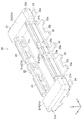
ヘッダ20は、上述したようにヘッダハウジング21を備えている。このヘッダハウジング21は、本実施形態では、絶縁性の合成樹脂によって平面視で全体的に矩形(長方形)状に成形されている(図1から図6参照)。   The header 20 includes the header housing 21 as described above. In the present embodiment, the header housing 21 is formed into an overall rectangular (rectangular) shape in plan view with an insulating synthetic resin (see FIGS. 1 to 6).

そして、ヘッダハウジング21には、金属製のヘッダ側信号用端子22および金属製のヘッダ側電源用端子23が配設されている。ヘッダ側信号用端子22は、信号線に電気的に接続されて信号を伝達するために用いられる端子である。一方、ヘッダ側電源用端子23は、電源線に電気的に接続されて電源を供給するために用いられる端子である。   The header housing 21 is provided with a metal header-side signal terminal 22 and a metal header-side power supply terminal 23. The header-side signal terminal 22 is a terminal that is electrically connected to the signal line and used to transmit a signal. On the other hand, the header-side power supply terminal 23 is a terminal that is electrically connected to a power supply line and used to supply power.

本実施形態では、ヘッダハウジング21の一方の長辺に沿って、1つのヘッダ側信号用端子22と2つのヘッダ側電源用端子23が、互いに離間するように並設されている。そして、ヘッダハウジング21の幅方向(短手方向)Yの一方側に並設された1つのヘッダ側信号用端子22および2つのヘッダ側電源用端子23で、ヘッダ側端子群G1を構成している。   In the present embodiment, one header side signal terminal 22 and two header side power supply terminals 23 are juxtaposed along one long side of the header housing 21 so as to be separated from each other. The header-side terminal group G1 is configured by one header-side signal terminal 22 and two header-side power supply terminals 23 arranged side by side in the width direction (short direction) Y of the header housing 21. Yes.

また、ヘッダハウジング21の他方の長辺に沿っても、1つのヘッダ側信号用端子22と2つのヘッダ側電源用端子23が、互いに離間するように並設されている。そして、ヘッダハウジング21の幅方向(短手方向)Yの他方側に並設された1つのヘッダ側信号用端子22および2つのヘッダ側電源用端子23も、ヘッダ側端子群G1を構成している。   Also, along the other long side of the header housing 21, one header-side signal terminal 22 and two header-side power terminals 23 are arranged in parallel so as to be separated from each other. One header side signal terminal 22 and two header side power supply terminals 23 arranged in parallel on the other side in the width direction (short direction) Y of the header housing 21 also constitute the header side terminal group G1. Yes.

このように、本実施形態では、ヘッダハウジング21には、当該ヘッダハウジング21の長手方向Xに沿って配設されたヘッダ側信号用端子22およびヘッダ側電源用端子23で構成されるヘッダ側端子群G1が2列(複数列)配置されている。   As described above, in the present embodiment, the header housing 21 includes a header-side terminal including the header-side signal terminal 22 and the header-side power supply terminal 23 arranged along the longitudinal direction X of the header housing 21. The group G1 is arranged in two rows (a plurality of rows).

また、1列のヘッダ側端子群G1には、ヘッダ側信号用端子22の両端にヘッダ側電源用端子23がそれぞれ配置されている。言い換えると、ヘッダ側電源用端子23がヘッダハウジング21の長手方向Xの両端に配設されるとともに、ヘッダ側電源用端子23の間にヘッダ側信号用端子22が配設されている。このように、本実施形態では、ヘッダ側信号用端子22よりもヘッダハウジング21の長手方向Xの外側に配設されるヘッダ側電源用端子23を有している。   In addition, header-side power supply terminals 23 are arranged at both ends of the header-side signal terminal 22 in the header-side terminal group G1 in one row. In other words, the header-side power terminals 23 are disposed at both ends in the longitudinal direction X of the header housing 21, and the header-side signal terminals 22 are disposed between the header-side power terminals 23. Thus, in the present embodiment, the header-side power supply terminal 23 is disposed outside the header-side signal terminal 22 in the longitudinal direction X of the header housing 21.

さらに、本実施形態では、ヘッダハウジング21の長手方向Xの両端に、金属製のヘッダ側保持金具24が配設されている。このヘッダ側保持金具24は、ヘッダハウジング21の強度を高めるとともに、ヘッダ側保持金具24が有する固定端子24aを上述した第2の回路基板40に取付固定するために用いられるものである。   Furthermore, in this embodiment, the metal header side holding | maintenance metal fitting 24 is arrange | positioned at the both ends of the longitudinal direction X of the header housing 21. As shown in FIG. The header side holding metal fitting 24 is used to increase the strength of the header housing 21 and to attach and fix the fixing terminal 24a included in the header side holding metal fitting 24 to the second circuit board 40 described above.

次に、図4から図6を参照しながら、ヘッダハウジング21の構成を説明する。   Next, the configuration of the header housing 21 will be described with reference to FIGS. 4 to 6.

ヘッダハウジング21は、板状壁部21aと、その周縁部に沿って略矩形環状に連続的に形成される周壁部21bとで一方側(図5の下側)が開口した略箱状に形成されており、周壁部21bの内方に凹部21c(図1参照)が形成されている。そして、周壁部21bの外周側下端には、外側に向かうにつれて上方(板状壁部21a側)に位置するように傾斜したテーパ部21dが形成されている。このテーパ部21dは、周壁部21bの長手方向壁部21eの長手方向両端および周壁部21bの短手方向壁部21fの幅方向Y全体に形成されている。すなわち、ヘッダハウジング21の長手方向X両端に、短手方向壁部21fと当該短手方向壁部21fの幅方向Yの両端に連続する長手方向壁部21eの長手方向端部とで、平面視(裏面視)で略U字状のテーパ部21dがそれぞれ形成されている。   The header housing 21 is formed in a substantially box shape in which one side (the lower side in FIG. 5) is opened by a plate-like wall portion 21a and a peripheral wall portion 21b continuously formed in a substantially rectangular ring shape along the peripheral edge portion. A recess 21c (see FIG. 1) is formed inside the peripheral wall portion 21b. And the taper part 21d which inclined so that it may be located in the upper part (plate-shaped wall part 21a side) toward the outer side is formed in the outer peripheral side lower end of the surrounding wall part 21b. This taper part 21d is formed in the longitudinal direction both ends of the longitudinal direction wall part 21e of the surrounding wall part 21b, and the whole width direction Y of the transversal direction wall part 21f of the surrounding wall part 21b. That is, in the longitudinal direction X both ends of the header housing 21, the short-side wall portion 21f and the long-side end portion of the long-side wall portion 21e continuous to both ends in the width direction Y of the short-side wall portion 21f are seen in a plan view. A substantially U-shaped tapered portion 21d is formed (as viewed from the back).

なお、隣り合うヘッダ側信号用端子22とヘッダ側電源用端子23との間の周壁部21bは、R状(逆U字状)に湾曲形成されている。   The peripheral wall portion 21b between the adjacent header-side signal terminals 22 and header-side power supply terminals 23 is curved in an R shape (inverted U shape).

また、短手方向壁部21fの幅方向Yの長さが、対向する2つの長手方向壁部21e間の距離よりも大きくなるように形成されており、ヘッダハウジング21は、全体的に平面視略I字状に形成されている。   Further, the length in the width direction Y of the short-side wall portion 21f is formed to be larger than the distance between the two opposing longitudinal-direction wall portions 21e, and the header housing 21 is entirely viewed in plan view. It is formed in a substantially I shape.

次に、図7から図9を参照しながら、ヘッダ側信号用端子22の構成を説明する。   Next, the configuration of the header-side signal terminal 22 will be described with reference to FIGS.

ヘッダ側信号用端子22は、金属成形により製造されており、導電体である。そして、このヘッダ側信号用端子22は、ヘッダハウジング21の側面から突出する付け根部22aを備えている。付け根部22aは、第2の回路基板40の回路パターン41に半田50によって固定される部位である。また、付け根部22aの上面は、図29から分かるように、ヘッダハウジング21の上面(板状壁部21aの外表面)に対して略平行に延びている。   The header-side signal terminal 22 is manufactured by metal forming and is a conductor. The header-side signal terminal 22 includes a base portion 22 a that protrudes from the side surface of the header housing 21. The base portion 22 a is a portion that is fixed to the circuit pattern 41 of the second circuit board 40 with solder 50. Further, as can be seen from FIG. 29, the upper surface of the base portion 22a extends substantially parallel to the upper surface of the header housing 21 (the outer surface of the plate-like wall portion 21a).

また、ヘッダ側信号用端子22は、付け根部22aに連続する内側部22bを備えている。内側部22bは、ヘッダハウジング21の板状壁部21aと長手方向壁部21eとの接合部を曲がりながら貫通し、長手方向壁部21eの内表面に沿って長手方向壁部21eの先端部まで延びている。   The header-side signal terminal 22 includes an inner portion 22b continuous with the base portion 22a. The inner portion 22b passes through the joint portion between the plate-like wall portion 21a and the longitudinal wall portion 21e of the header housing 21 while bending, and extends to the distal end portion of the longitudinal wall portion 21e along the inner surface of the longitudinal wall portion 21e. It extends.

そして、ヘッダ側信号用端子22の内側部22bの内側表面上には、凹部22cが形成されている。本実施形態では、凹部22cは、平坦状の奥面22gと、奥面22gの長手方向Xの両側に連設された傾斜面22hと、奥面22gの上下方向Zの両側に連設された傾斜面22iとで、略四角錐台状に形成されている。この凹部22cには、後述するソケット側信号用端子32の円弧状突起部32kが嵌まり込む。   A concave portion 22 c is formed on the inner surface of the inner portion 22 b of the header-side signal terminal 22. In the present embodiment, the recess 22c is connected to both the flat back surface 22g, the inclined surfaces 22h connected to both sides of the back surface 22g in the longitudinal direction X, and both sides of the back surface 22g in the vertical direction Z. The inclined surface 22i is formed in a substantially square frustum shape. An arcuate protrusion 32k of a socket-side signal terminal 32, which will be described later, is fitted into the recess 22c.

さらに、ヘッダ側信号用端子22は、内側部22bの一方端に連続する先端部22dを備えている。先端部22dは、ヘッダハウジング21の長手方向壁部21eの先端の形状に沿って曲がっている。   Further, the header-side signal terminal 22 includes a tip 22d that is continuous with one end of the inner portion 22b. The distal end portion 22d is bent along the shape of the distal end of the longitudinal wall portion 21e of the header housing 21.

ヘッダ側信号用端子22は、先端部22dに連続する被係止部22eを備えている。本実施形態では、被係止部22eは、ヘッダ側信号用端子22におけるヘッダハウジング21の長手方向Xの一端から他端にかけて形成されている。すなわち、ヘッダ側信号用端子22の幅方向全体に亘って、段差状の被係止部22eが形成されている。   The header-side signal terminal 22 includes a locked portion 22e that is continuous with the tip portion 22d. In the present embodiment, the locked portion 22e is formed from one end to the other end of the header-side signal terminal 22 in the longitudinal direction X of the header housing 21. That is, a stepped locked portion 22 e is formed over the entire width direction of the header-side signal terminal 22.

この被係止部22eは、図29および図30を対比すれば分かるように、ヘッダ側信号用端子22がソケット側信号用端子32に嵌め込まれるときに、段差部としての係止部32dよりも奥へ挿入される。そのため、被係止部22eは、ヘッダ側信号用端子22がソケット側信号用端子32から引き抜かれるときに、係止部32dに当接する。つまり、ヘッダ側信号用端子22の被係止部22eは、ソケット側信号用端子32の係止部32dによって係止される。したがって、ヘッダ側信号用端子22のソケット側信号用端子32からの引き抜けが抑制されている。つまり、ヘッダ側信号用端子22は、所定値よりも小さな外力をかけただけでは、ソケット側信号用端子32から引き抜くことができない。一方、ヘッダ側信号用端子22は、所定値以上の大きな外力をかけると、ソケット側信号用端子32から引き抜かれ得る。つまり、ヘッダ側信号用端子22の被係止部22eおよびソケット側信号用端子32の係止部32dは、所定値以上の外力を加えることにより、互いの係止を解除することが可能なロック機構を構成している。   As can be seen by comparing FIG. 29 and FIG. 30, the locked portion 22 e is more than the locking portion 32 d as the stepped portion when the header-side signal terminal 22 is fitted into the socket-side signal terminal 32. It is inserted in the back. Therefore, the locked portion 22e contacts the locking portion 32d when the header-side signal terminal 22 is pulled out from the socket-side signal terminal 32. That is, the locked portion 22 e of the header side signal terminal 22 is locked by the locking portion 32 d of the socket side signal terminal 32. Accordingly, the withdrawal of the header-side signal terminal 22 from the socket-side signal terminal 32 is suppressed. That is, the header-side signal terminal 22 cannot be pulled out from the socket-side signal terminal 32 only by applying an external force smaller than a predetermined value. On the other hand, the header-side signal terminal 22 can be pulled out from the socket-side signal terminal 32 when a large external force of a predetermined value or more is applied. In other words, the locked portion 22e of the header-side signal terminal 22 and the locking portion 32d of the socket-side signal terminal 32 can be unlocked by applying an external force of a predetermined value or more. The mechanism is configured.

被係止部22eは、ヘッダ側信号用端子22の厚さを部分的に異ならせる母材の圧延により製造されてもよいが、ヘッダ側信号用端子22の母材を厚さ方向に曲げる成形により製造されてもよい。   The locked portion 22e may be manufactured by rolling a base material that partially varies the thickness of the header-side signal terminal 22, but is formed by bending the base material of the header-side signal terminal 22 in the thickness direction. May be manufactured.

さらに、ヘッダ側信号用端子22は、被係止部22eを介して、先端部22dに連続し、長手方向壁部21eの外表面に沿って延びる外側部22fを備えている。本実施形態では、長手方向壁部21e(周壁部21b)の外周に突設された突出壁部21gによって、ヘッダ側信号用端子22の外側部22f先端の位置決めがなされている。   Further, the header-side signal terminal 22 includes an outer portion 22f that is continuous with the distal end portion 22d through the locked portion 22e and extends along the outer surface of the longitudinal wall portion 21e. In the present embodiment, the distal end of the outer side portion 22f of the header-side signal terminal 22 is positioned by the protruding wall portion 21g protruding from the outer periphery of the longitudinal wall portion 21e (the peripheral wall portion 21b).

このようなヘッダ側信号用端子22は、所定厚さを持った帯状の金属材を湾曲成形することにより形成することができる。   Such a header-side signal terminal 22 can be formed by bending a strip-shaped metal material having a predetermined thickness.

また、本実施形態では、ヘッダ側信号用端子22は、インサート成形によってヘッダハウジング21に配設されるようにしている。なお、ヘッダ側信号用端子22をヘッダハウジング21に圧入することで、ヘッダ側信号用端子22をヘッダハウジング21に配設させるようにしてもよい。   In the present embodiment, the header-side signal terminal 22 is arranged in the header housing 21 by insert molding. The header-side signal terminals 22 may be disposed in the header housing 21 by press-fitting the header-side signal terminals 22 into the header housing 21.

次に、図10から図12を参照しながら、ヘッダ側電源用端子23の構成を説明する。   Next, the configuration of the header-side power supply terminal 23 will be described with reference to FIGS. 10 to 12.

ヘッダ側電源用端子23は、金属成形により製造されており、導電体である。そして、このヘッダ側電源用端子23は、ヘッダハウジング21の側面から突出する付け根部23aを備えている。付け根部23aは、第2の回路基板40の回路パターン41に半田50によって固定される部位である。また、付け根部23aの上面は、図31から分かるように、ヘッダハウジング21の上面(板状壁部21aの外表面)に対して略平行に延びている。   The header-side power supply terminal 23 is manufactured by metal forming and is a conductor. The header-side power supply terminal 23 includes a base portion 23 a that protrudes from the side surface of the header housing 21. The base portion 23 a is a portion that is fixed to the circuit pattern 41 of the second circuit board 40 by the solder 50. Further, as can be seen from FIG. 31, the upper surface of the base portion 23a extends substantially parallel to the upper surface of the header housing 21 (the outer surface of the plate-like wall portion 21a).

また、ヘッダ側電源用端子23は、付け根部23aに連続する内側部23bを備えている。内側部23bは、ヘッダハウジング21の板状壁部21aと長手方向壁部21eとの接合部を曲がりながら貫通し、長手方向壁部21eの内表面に沿って長手方向壁部21eの先端部まで延びている。   The header-side power supply terminal 23 includes an inner portion 23b that is continuous with the base portion 23a. The inner side part 23b penetrates the joining part of the plate-like wall part 21a and the longitudinal wall part 21e of the header housing 21 while bending, and extends to the front end part of the longitudinal wall part 21e along the inner surface of the longitudinal wall part 21e. It extends.

そして、ヘッダ側電源用端子23の内側部23bの内側表面上には、凹部23cが形成されている。本実施形態では、凹部23cは、平坦状の奥面23gと、奥面23gの長手方向Xの両側に連設された傾斜面23hと、奥面23gの上下方向Zの両側に連設された傾斜面23iとで、略四角錐台状に形成されている。この凹部23cには、後述するソケット側電源用端子33の円弧状突起部33kが嵌まり込む。   A concave portion 23 c is formed on the inner surface of the inner portion 23 b of the header-side power supply terminal 23. In the present embodiment, the recess 23c is connected to both sides of the flat back surface 23g, the inclined surfaces 23h connected to both sides of the back surface 23g in the longitudinal direction X, and the back surface 23g in the vertical direction Z. The inclined surface 23i is formed in a substantially quadrangular pyramid shape. An arc-shaped protrusion 33k of a socket-side power supply terminal 33 to be described later is fitted into the recess 23c.

さらに、ヘッダ側電源用端子23は、内側部23bの一方端に連続する先端部23dを備えている。先端部23dは、ヘッダハウジング21の長手方向壁部21eの先端の形状に沿って曲がっている。   Furthermore, the header-side power supply terminal 23 includes a distal end portion 23d that is continuous with one end of the inner side portion 23b. The distal end portion 23 d is bent along the shape of the distal end of the longitudinal wall portion 21 e of the header housing 21.

ヘッダ側電源用端子23は、先端部23dに連続する被係止部23eを備えている。図31および図32を対比すれば分かるように、被係止部23eは、ヘッダ側電源用端子23がソケット側電源用端子33に嵌め込まれるときに、段差部としての係止部33dよりも奥へ挿入される。そのため、被係止部23eは、ヘッダ側電源用端子23がソケット側電源用端子33から引き抜かれるときに、係止部33dに当接する。つまり、ヘッダ側電源用端子23の被係止部23eは、ソケット側電源用端子33の係止部33dによって係止される。したがって、ヘッダ側電源用端子23のソケット側電源用端子33からの引き抜けが抑制されている。つまり、ヘッダ側電源用端子23は、所定値よりも小さな外力をかけただけでは、ソケット側電源用端子33から引き抜くことができない。一方、ヘッダ側電源用端子23は、所定値以上の大きな外力をかけると、ソケット側電源用端子33から引き抜かれ得る。つまり、ヘッダ側電源用端子23の被係止部23eおよびソケット側電源用端子33の係止部33dは、所定値以上の外力を加えることにより、互いの係止を解除することが可能なロック機構を構成している。   The header-side power supply terminal 23 includes a locked portion 23e that is continuous with the distal end portion 23d. As can be seen by comparing FIG. 31 and FIG. 32, the locked portion 23e is deeper than the locking portion 33d as a step when the header-side power supply terminal 23 is fitted into the socket-side power supply terminal 33. Is inserted. Therefore, the locked portion 23e comes into contact with the locking portion 33d when the header-side power supply terminal 23 is pulled out from the socket-side power supply terminal 33. That is, the locked portion 23 e of the header-side power supply terminal 23 is locked by the locking portion 33 d of the socket-side power supply terminal 33. Accordingly, pulling out of the header side power supply terminal 23 from the socket side power supply terminal 33 is suppressed. That is, the header-side power supply terminal 23 cannot be pulled out from the socket-side power supply terminal 33 only by applying an external force smaller than a predetermined value. On the other hand, the header-side power supply terminal 23 can be pulled out from the socket-side power supply terminal 33 when a large external force of a predetermined value or more is applied. That is, the locked portion 23e of the header-side power supply terminal 23 and the locking portion 33d of the socket-side power supply terminal 33 can be unlocked by applying an external force of a predetermined value or more. The mechanism is configured.

被係止部23eは、ヘッダ側電源用端子23の厚さを部分的に異ならせる母材の圧延により製造されてもよいが、ヘッダ側電源用端子23の母材を厚さ方向に曲げる成形により製造されてもよい。   The locked portion 23e may be manufactured by rolling a base material that partially varies the thickness of the header-side power supply terminal 23, but is formed by bending the base material of the header-side power supply terminal 23 in the thickness direction. May be manufactured.

さらに、ヘッダ側電源用端子23は、被係止部23eを介して、先端部23dに連続し、長手方向壁部21eの外表面に沿って延びる外側部23fを備えている。さらに、本実施形態では、長手方向壁部21e(周壁部21b)の外周に突設された突出壁部21hによって、ヘッダ側電源用端子23の外側部23f先端の位置決めがなされている。   Further, the header-side power supply terminal 23 includes an outer portion 23f that is continuous with the distal end portion 23d through the locked portion 23e and extends along the outer surface of the longitudinal wall portion 21e. Furthermore, in the present embodiment, the distal end of the outer side portion 23f of the header-side power supply terminal 23 is positioned by the protruding wall portion 21h that protrudes from the outer periphery of the longitudinal wall portion 21e (the peripheral wall portion 21b).

このように、本実施形態では、ヘッダ側信号用端子22の側断面形状とヘッダ側電源用端子23の側断面形状とが略同一形状をしている(図9(a)および図12(a)参照)。   Thus, in this embodiment, the side cross-sectional shape of the header-side signal terminal 22 and the side cross-sectional shape of the header-side power supply terminal 23 are substantially the same shape (FIGS. 9A and 12A). )reference).

また、上述したように、ヘッダ側信号用端子22およびヘッダ側電源用端子23は、ヘッダハウジング21の長手方向Xに沿って配設されている。そして、本実施形態では、ヘッダ側電源用端子23は、ヘッダハウジング21の長手方向Xに沿った幅が、ヘッダ側信号用端子22の長手方向Xに沿った幅よりも広くなるように形成されている。   As described above, the header-side signal terminal 22 and the header-side power supply terminal 23 are arranged along the longitudinal direction X of the header housing 21. In the present embodiment, the header-side power supply terminal 23 is formed such that the width along the longitudinal direction X of the header housing 21 is wider than the width along the longitudinal direction X of the header-side signal terminal 22. ing.

すなわち、本実施形態では、ヘッダ側電源用端子23よりもヘッダハウジング21の長手方向Xの幅が狭いヘッダ側信号用端子22を有するようにしている。なお、本実施形態では、全てのヘッダ側信号用端子22が、ヘッダ側電源用端子23よりもヘッダハウジング21の長手方向Xの幅が狭くなっている。   That is, in the present embodiment, the header-side signal terminal 22 is narrower in the longitudinal direction X of the header housing 21 than the header-side power supply terminal 23. In the present embodiment, all header-side signal terminals 22 are narrower in the longitudinal direction X of the header housing 21 than the header-side power terminals 23.

このように、ヘッダ側電源用端子23におけるヘッダハウジング21の長手方向Xに沿った幅を広くしているため、付け根部23aの長手方向X中央部に、凹状に切り欠かれた形状をした凹部23jを形成している。この凹部23jを形成することで、付け根部23aの突出量の増加を抑制しつつ、付け根部23aの回路パターンに接する輪郭線の長さを長くすることができる。また、輪郭線の形状をより複雑な形状となるようにすることができる。こうすることで、凹部23jを形成しない場合に較べて、幅広のヘッダ側電源用端子23を第2の回路基板40の回路パターン41に半田50によって固定する際の、付け根部23aと回路パターン41との半田50による固定強度が高くなる。   Thus, since the width along the longitudinal direction X of the header housing 21 in the header-side power supply terminal 23 is widened, the concave portion having a concave shape at the center in the longitudinal direction X of the base portion 23a. 23j is formed. By forming the concave portion 23j, it is possible to increase the length of the contour line in contact with the circuit pattern of the base portion 23a while suppressing an increase in the protruding amount of the base portion 23a. In addition, the shape of the contour line can be made more complicated. In this way, compared to the case where the recess 23j is not formed, the base 23a and the circuit pattern 41 when the wide header-side power supply terminal 23 is fixed to the circuit pattern 41 of the second circuit board 40 by the solder 50 are used. The fixing strength by the solder 50 increases.

また、ヘッダ側電源用端子23の内側部23bの内側表面上には、長手方向Xに沿って、2つの凹部23cが形成されており、後述するソケット側電源用端子33の2つの円弧状突起部33kがそれぞれ嵌まり込むようになっている。   Further, on the inner surface of the inner portion 23b of the header-side power supply terminal 23, two concave portions 23c are formed along the longitudinal direction X, and two arc-shaped protrusions of the socket-side power supply terminal 33 described later. Each of the portions 33k is fitted.

さらに、本実施形態では、被係止部23eが、ヘッダ側電源用端子23におけるヘッダハウジング21の長手方向Xの一端から他端にかけて形成されている。すなわち、幅広のヘッダ側電源用端子23の幅方向全体に亘って、段差状の被係止部23eを形成している。こうすることで、ヘッダ側電源用端子23の被係止部23eおよびソケット側電源用端子33の係止部33dによるロック力を向上させることができる。また、ヘッダ20およびソケット30の挿抜を繰り返した際にも、被係止部23eが摩耗しにくくなるため、製品の長寿命化を図ることが可能となる。   Furthermore, in this embodiment, the to-be-latched part 23e is formed from one end of the longitudinal direction X of the header housing 21 in the header side power supply terminal 23 to the other end. That is, a stepped locked portion 23e is formed over the entire width direction of the wide header-side power supply terminal 23. By doing so, the locking force by the locked portion 23e of the header-side power supply terminal 23 and the locking portion 33d of the socket-side power supply terminal 33 can be improved. In addition, when the insertion and removal of the header 20 and the socket 30 are repeated, the locked portion 23e is less likely to be worn, so that the product life can be extended.

このようなヘッダ側電源用端子23は、所定厚さを持った帯状の金属材を湾曲成形することにより形成することができる。   Such a header-side power supply terminal 23 can be formed by bending a band-shaped metal material having a predetermined thickness.

また、本実施形態では、ヘッダ側電源用端子23は、インサート成形によってヘッダハウジング21に配設されるようにしている。なお、ヘッダ側電源用端子23をヘッダハウジング21に圧入することで、ヘッダ側電源用端子23をヘッダハウジング21に配設させるようにしてもよい。   In the present embodiment, the header-side power supply terminal 23 is arranged in the header housing 21 by insert molding. The header-side power supply terminal 23 may be disposed in the header housing 21 by press-fitting the header-side power supply terminal 23 into the header housing 21.

次に、図13および図14を参照しながら、ヘッダ側保持金具24の構成を説明する。   Next, the structure of the header side holding | maintenance metal fitting 24 is demonstrated, referring FIG. 13 and FIG.

ヘッダ側保持金具24は、ヘッダ側信号用端子22やヘッダ側電源用端子23と同様に金属成形により製造されている。   The header side holding metal fitting 24 is manufactured by metal forming similarly to the header side signal terminal 22 and the header side power supply terminal 23.

ヘッダ側保持金具24は、ヘッダハウジング21の側面から突出する固定端子24aを備えている。固定端子24aは、第2の回路基板40の回路パターン41に半田50によって固定される部位である。また、固定端子24aの上面も、ヘッダハウジング21の上面(板状壁部21aの外表面)に対して略平行に延びている。   The header-side holding bracket 24 includes a fixed terminal 24 a that protrudes from the side surface of the header housing 21. The fixed terminal 24 a is a part that is fixed to the circuit pattern 41 of the second circuit board 40 by the solder 50. The upper surface of the fixed terminal 24a also extends substantially parallel to the upper surface of the header housing 21 (the outer surface of the plate-like wall portion 21a).

また、ヘッダ側保持金具24は、固定端子24aに連続する内側部24bを備えている。この内側部24bには、長手方向Xの一方側に開口した切り欠き24cが形成されている。このような切り欠き24cを内側部24bに形成することで、ヘッダハウジング21とヘッダ側保持金具24とをより密着させることができるようになり、ヘッダハウジング21の強度をより高めることができる。   Further, the header side holding metal fitting 24 includes an inner portion 24b continuous with the fixed terminal 24a. The inner portion 24b is formed with a notch 24c opened on one side in the longitudinal direction X. By forming such a notch 24c in the inner portion 24b, the header housing 21 and the header-side holding metal fitting 24 can be more closely attached, and the strength of the header housing 21 can be further increased.

また、本実施形態では、ヘッダ側保持金具24は、インサート成形によってヘッダハウジング21に配設されるようにしている。なお、ヘッダ側保持金具24をヘッダハウジング21に圧入することで、ヘッダ側保持金具24をヘッダハウジング21に配設させるようにしてもよい。   Moreover, in this embodiment, the header side holding | maintenance metal fitting 24 is arrange | positioned by the header housing 21 by insert molding. The header side holding metal fitting 24 may be disposed in the header housing 21 by press-fitting the header side holding metal fitting 24 into the header housing 21.

次に、図15から図28を用いてコネクタ10で用いられるソケット30の構成を説明する。   Next, the structure of the socket 30 used with the connector 10 is demonstrated using FIGS. 15-28.

ソケット30は、上述したようにソケットハウジング31を備えている。このソケットハウジング31は、本実施形態では、絶縁性の合成樹脂によって平面視で全体的に矩形(長方形)状に成形されている(図15から図20参照)。   The socket 30 includes the socket housing 31 as described above. In this embodiment, the socket housing 31 is formed into an overall rectangular (rectangular) shape in plan view with an insulating synthetic resin (see FIGS. 15 to 20).

そして、ソケットハウジング31には、金属製のソケット側信号用端子32および金属製のソケット側電源用端子33が配設されている。ソケット側信号用端子32は、信号線に電気的に接続されて信号を伝達するために用いられる端子である。一方、ソケット側電源用端子33は、電源線に電気的に接続されて電源を供給するために用いられる端子である。   The socket housing 31 is provided with a metal socket-side signal terminal 32 and a metal socket-side power supply terminal 33. The socket-side signal terminal 32 is a terminal that is electrically connected to a signal line and used to transmit a signal. On the other hand, the socket-side power supply terminal 33 is a terminal that is electrically connected to a power supply line and used to supply power.

本実施形態では、ソケットハウジング31の一方の長辺に沿って、1つのソケット側信号用端子32と2つのソケット側電源用端子33が、互いに離間するように並設されている。そして、ソケットハウジング31の幅方向(短手方向)Yの一方側に並設された1つのソケット側信号用端子32および2つのソケット側電源用端子33で、ソケット側端子群G2を構成している。   In the present embodiment, one socket-side signal terminal 32 and two socket-side power supply terminals 33 are juxtaposed along one long side of the socket housing 31 so as to be separated from each other. The socket-side terminal group G2 is composed of one socket-side signal terminal 32 and two socket-side power supply terminals 33 arranged in parallel on one side in the width direction (short direction) Y of the socket housing 31. Yes.

また、ソケットハウジング31の他方の長辺に沿っても、1つのソケット側信号用端子32と2つのソケット側電源用端子33が、互いに離間するように並設されている。そして、ソケットハウジング31の幅方向(短手方向)Yの他方側に並設された1つのソケット側信号用端子32および2つのソケット側電源用端子33も、ソケット側端子群G2を構成している。   Also, along the other long side of the socket housing 31, one socket-side signal terminal 32 and two socket-side power terminals 33 are arranged in parallel so as to be separated from each other. One socket-side signal terminal 32 and two socket-side power terminals 33 arranged in parallel on the other side in the width direction (short direction) Y of the socket housing 31 also constitute the socket-side terminal group G2. Yes.

このように、本実施形態では、ソケットハウジング31には、当該ソケットハウジング31の長手方向Xに沿って配設されたソケット側信号用端子32およびソケット側電源用端子33で構成されるソケット側端子群G2が2列(複数列)配置されている。   As described above, in the present embodiment, the socket housing 31 includes the socket-side signal terminal 32 and the socket-side power supply terminal 33 arranged along the longitudinal direction X of the socket housing 31. The group G2 is arranged in two rows (a plurality of rows).

また、1列のソケット側端子群G2には、ソケット側信号用端子32の両端にソケット側電源用端子33がそれぞれ配置されている。言い換えると、ソケット側電源用端子33がソケットハウジング31の長手方向Xの両端に配設されるとともに、ソケット側電源用端子33の間にソケット側信号用端子32が配設されている。このように、本実施形態では、ソケット側信号用端子32よりもソケットハウジング31の長手方向Xの外側に配設されるソケット側電源用端子33を有している。   Further, in one row of the socket-side terminal group G2, socket-side power supply terminals 33 are arranged at both ends of the socket-side signal terminal 32, respectively. In other words, the socket-side power terminals 33 are disposed at both ends in the longitudinal direction X of the socket housing 31, and the socket-side signal terminals 32 are disposed between the socket-side power terminals 33. As described above, in this embodiment, the socket-side power supply terminal 33 is disposed outside the socket-side signal terminal 32 in the longitudinal direction X of the socket housing 31.

なお、ソケット側信号用端子32およびソケット側電源用端子33は、ヘッダ20とソケット30とを嵌合させた際に、対応するヘッダ側信号用端子22およびヘッダ側電源用端子23にそれぞれ接触するように、ソケットハウジング31に配設されている。   The socket-side signal terminal 32 and the socket-side power supply terminal 33 come into contact with the corresponding header-side signal terminal 22 and header-side power supply terminal 23 when the header 20 and the socket 30 are fitted. As described above, the socket housing 31 is disposed.

さらに、本実施形態では、ソケットハウジング31の長手方向Xの両端に、金属製のソケット側保持金具34が配設されている。このソケット側保持金具34は、ソケットハウジング31の強度を高めるとともに、ソケット側保持金具34が有する固定端子34dを上述した第1の回路基板60に取付固定するために用いられるものである。   Furthermore, in the present embodiment, metal socket-side holding metal fittings 34 are disposed at both ends in the longitudinal direction X of the socket housing 31. The socket side holding metal fitting 34 is used to increase the strength of the socket housing 31 and to attach and fix the fixing terminal 34d of the socket side holding metal fitting 34 to the first circuit board 60 described above.

次に、図18から図20を参照しながら、ソケットハウジング31の構成を説明する。   Next, the configuration of the socket housing 31 will be described with reference to FIGS.

ソケットハウジング31は、板状壁部31aと、その周縁部に沿って略矩形環状に連続的に形成される周壁部31bとで一方側(図15の上側)が開口した略箱状に形成されている。さらに、本実施形態では、板状壁部31aの中央部に、周壁部31bから所定間隔をあけて略矩形状の島部31cが形成されている。そして、これら周壁部31bと島部31cとの間にヘッダ20の周壁部21bを嵌合するための略枠状の嵌合溝部31dが形成されている。なお、島部31cは、凹部21cに嵌合される。   The socket housing 31 is formed in a substantially box shape in which one side (the upper side in FIG. 15) is opened by a plate-like wall portion 31a and a peripheral wall portion 31b continuously formed in a substantially rectangular annular shape along the peripheral edge portion. ing. Furthermore, in this embodiment, the substantially rectangular island part 31c is formed in the center part of the plate-shaped wall part 31a at predetermined intervals from the surrounding wall part 31b. A substantially frame-shaped fitting groove 31d for fitting the peripheral wall 21b of the header 20 is formed between the peripheral wall 31b and the island 31c. In addition, the island part 31c is fitted by the recessed part 21c.

また、嵌合溝部31dには、短手方向壁部21fおよび長手方向壁部21eが嵌合されるため、嵌合溝部31dは、長手方向Yの両端部が幅広となるように形成されている。   Further, since the short-side wall portion 21f and the long-side wall portion 21e are fitted to the fitting groove portion 31d, the fitting groove portion 31d is formed so that both end portions in the longitudinal direction Y are wide. .

さらに、本実施形態では、周壁部31dの内周側上端に、内側に向かうにつれて下方(板状壁部31a側)に位置するように傾斜したテーパ部31eが形成されている。このテーパ部31eは、周壁部31bの長手方向壁部31hの長手方向両端および周壁部31bの短手方向壁部31iに形成されている。また、隣り合うソケット側信号用端子32とソケット側電源用端子33との間の周壁部31bにもテーパ部31eが形成されている。このように、本実施形態では、周壁部31bのほぼ全周にわたってテーパ部31eが形成されている。   Furthermore, in this embodiment, the taper part 31e which inclined so that it may be located below (plate-shaped wall part 31a side) is formed in the inner peripheral side upper end of the surrounding wall part 31d as it goes inside. This taper part 31e is formed in the longitudinal direction both ends of the longitudinal direction wall part 31h of the surrounding wall part 31b, and the transversal direction wall part 31i of the surrounding wall part 31b. Further, a tapered portion 31e is also formed on the peripheral wall portion 31b between the adjacent socket-side signal terminal 32 and the socket-side power supply terminal 33. Thus, in this embodiment, the taper part 31e is formed over the perimeter of the surrounding wall part 31b.

また、本実施形態では、ソケットハウジング31には、ソケット側信号用端子32が収容されるソケット側信号用端子収容部31fが板状壁部31aを貫通するように形成されている(図18から図20参照)。また、ソケットハウジング31には、ソケット側電源用端子33が収容されるソケット側電源用端子収容部31gが板状壁部31aを貫通するように形成されている。   In this embodiment, the socket housing 31 is formed with a socket-side signal terminal accommodating portion 31f for accommodating the socket-side signal terminal 32 so as to penetrate the plate-like wall portion 31a (from FIG. 18). (See FIG. 20). The socket housing 31 is formed with a socket-side power supply terminal accommodating portion 31g for accommodating the socket-side power supply terminal 33 so as to penetrate the plate-like wall portion 31a.

ソケット側信号用端子収容部31fは、長手方向壁部31hにソケット側信号用端子収容凹部31jを嵌合溝部31dと連通するように形成するとともに、島部31cにソケット側信号用端子収容凹部31mを嵌合溝部31dと連通するように形成することで、形成されている。   The socket-side signal terminal accommodating portion 31f is formed in the longitudinal wall portion 31h so that the socket-side signal terminal accommodating recess portion 31j communicates with the fitting groove portion 31d, and the socket-side signal terminal accommodating recess portion 31m in the island portion 31c. Is formed so as to communicate with the fitting groove 31d.

また、ソケット側電源用端子収容部31gは、長手方向壁部31hにソケット側電源用端子収容凹部31kを嵌合溝部31dと連通するように形成するとともに、島部31cにソケット側電源用端子収容凹部31nを嵌合溝部31dと連通するように形成することで、形成されている。   In addition, the socket-side power terminal accommodating portion 31g is formed so that the socket-side power terminal accommodating recess 31k communicates with the fitting groove 31d in the longitudinal wall portion 31h, and the socket-side power terminal accommodating in the island portion 31c. The recess 31n is formed so as to communicate with the fitting groove 31d.

そして、ソケット側信号用端子32およびソケット側電源用端子33は、ソケットハウジング31の裏面側からソケット側信号用端子収容部31fおよびソケット側電源用端子収容部31gにそれぞれ圧入される。   The socket-side signal terminal 32 and the socket-side power supply terminal 33 are press-fitted from the back side of the socket housing 31 into the socket-side signal terminal accommodating portion 31f and the socket-side power supply terminal accommodating portion 31g, respectively.

次に、図21から図23を参照しながら、ソケット側信号用端子32の構成を説明する。   Next, the configuration of the socket-side signal terminal 32 will be described with reference to FIGS.

ソケット側信号用端子32は、金属成形により製造されており、導電体である。そして、このソケット側信号用端子32は、ソケットハウジング21の側面から突出する付け根部32aを備えている。付け根部32aは、第1の回路基板60の回路パターン61に半田70によって固定される部位である。また、付け根部32aの下面は、第1の回路基板60の主表面Mに沿って延び、ソケットハウジング31の底面(板状壁部31aの裏面)と同一平面内に位置付けられている。   The socket side signal terminal 32 is manufactured by metal forming and is a conductor. The socket-side signal terminal 32 includes a base portion 32 a that protrudes from the side surface of the socket housing 21. The base portion 32 a is a portion that is fixed to the circuit pattern 61 of the first circuit board 60 by the solder 70. The bottom surface of the base portion 32a extends along the main surface M of the first circuit board 60 and is positioned in the same plane as the bottom surface of the socket housing 31 (the back surface of the plate-like wall portion 31a).

ソケット側信号用端子32は、付け根部32aから立上がり、第1の回路基板60から離れるように延びる立上り部32bを備えている。立上り部32bは、付け根部32aから曲がってソケット側信号用端子収容凹部31j内に入り、長手方向壁部31hの内表面に沿って延びている。   The socket-side signal terminal 32 includes a rising portion 32 b that rises from the base portion 32 a and extends away from the first circuit board 60. The rising portion 32b is bent from the base portion 32a, enters the socket-side signal terminal accommodating recess 31j, and extends along the inner surface of the longitudinal wall portion 31h.

ソケット側信号用端子32は、立上り部32bの上端にその一方端が連続する反転U字状部32cを備えている。反転U字状部32cは、文字「U」が上下逆さまに配置された形状を有している。なお、反転U字状部32cは、先端面32nと、当該先端面32nの長手方向X両側に連設される傾斜面32pとを有しており、水平断面視で略台形状に突出する突状に形成されている(図23(b)参照)。   The socket-side signal terminal 32 includes an inverted U-shaped portion 32c having one end continuous with the upper end of the rising portion 32b. The inverted U-shaped portion 32c has a shape in which the letter “U” is arranged upside down. The inverted U-shaped part 32c has a tip surface 32n and inclined surfaces 32p provided on both sides in the longitudinal direction X of the tip surface 32n, and protrudes in a substantially trapezoidal shape in a horizontal sectional view. (See FIG. 23B).

ソケット側信号用端子32は、反転U字状部32cの他方端に連続する係止部32dを備えている。本実施形態では、係止部32dは、ソケット側信号用端子32におけるソケットハウジング31の長手方向Xの一端から他端にかけて形成されている。すなわち、ソケット側信号用端子32の幅方向全体に亘って、段差状の係止部32dが形成されている。   The socket-side signal terminal 32 includes a locking portion 32d that is continuous with the other end of the inverted U-shaped portion 32c. In the present embodiment, the locking portion 32 d is formed from one end to the other end in the longitudinal direction X of the socket housing 31 in the socket-side signal terminal 32. That is, a stepped locking portion 32 d is formed over the entire width direction of the socket-side signal terminal 32.

この係止部32dは、上述したように、ヘッダ側信号用端子22がソケット側信号用端子32から引き抜かれるときに、被係止部22eの移動を抑制する部分として機能する。つまり、ソケット側信号用端子32の係止部32dは、ヘッダ側信号用端子22の被係止部22eに当接し、被係止部22eを係止し得る。ソケット側信号用端子32の係止部32dおよびヘッダ側信号用端子22の被係止部22eは、所定値以上の外力を加えることにより、係止を解除することが可能なロック機構を構成している。   As described above, the locking portion 32d functions as a portion that suppresses the movement of the locked portion 22e when the header-side signal terminal 22 is pulled out from the socket-side signal terminal 32. That is, the locking portion 32d of the socket-side signal terminal 32 can abut on the locked portion 22e of the header-side signal terminal 22 to lock the locked portion 22e. The locking portion 32d of the socket-side signal terminal 32 and the locked portion 22e of the header-side signal terminal 22 constitute a locking mechanism that can be unlocked by applying an external force of a predetermined value or more. ing.

係止部32dは、ソケット側信号用端子32の厚さを部分的に異ならせる母材の圧延により製造されてもよいが、ソケット側信号用端子32の母材を厚さ方向に曲げる成形により製造されてもよい。   The locking portion 32d may be manufactured by rolling a base material that partially varies the thickness of the socket-side signal terminal 32, but is formed by bending the base material of the socket-side signal terminal 32 in the thickness direction. May be manufactured.

また、ソケット側信号用端子32は、係止部32dに連続し、立上り部32bにほぼ平行に延びる立下り部32eを有している。   The socket-side signal terminal 32 has a falling portion 32e that is continuous with the locking portion 32d and extends substantially parallel to the rising portion 32b.

そして、ソケット側信号用端子32は、立下り部32eの下端に連続する第1の円弧状部32fを備えている。   The socket-side signal terminal 32 includes a first arc-shaped portion 32f continuous to the lower end of the falling portion 32e.

ソケット側信号用端子32は、図29および図30に示すように、第1の円弧状部32fに連続する対向部32zを備えている。対向部32zは、次に説明する平坦部32g、第1の斜め部32h、第2の円弧状部32i、第2の斜め部32j、円弧状突起部32k、および先端部32mを含んでいる。対向部32zは、具体的には次のようなものである。   As shown in FIGS. 29 and 30, the socket-side signal terminal 32 includes a facing portion 32z that is continuous with the first arc-shaped portion 32f. The facing part 32z includes a flat part 32g, a first oblique part 32h, a second arcuate part 32i, a second oblique part 32j, an arcuate protrusion 32k, and a tip part 32m, which will be described next. Specifically, the facing portion 32z is as follows.

対向部32zは、傾斜部32fの下端に連続する平坦部32gを備えている。平坦部32gは、図29に示すように、立下り部32eから離れるように、第1の回路基板60の主表面Mに沿って延びている。ただし、平坦部32gは、主表面Mに平行である必要はない。平坦部32gは、後述するばね部のばね長を大きくするために設けられている。   The facing portion 32z includes a flat portion 32g continuous to the lower end of the inclined portion 32f. As shown in FIG. 29, the flat portion 32g extends along the main surface M of the first circuit board 60 so as to be separated from the falling portion 32e. However, the flat portion 32g does not need to be parallel to the main surface M. The flat portion 32g is provided to increase the spring length of a spring portion described later.

対向部32zは、図29に示すように、平坦部32gに連続し、第1の回路基板60の主表面Mに対して斜め方向に延びる第1の斜め部32hを備えている。第1の斜め部32hは、第1の回路基板60から離れるにしたがって、立下り部32eから離れるように延びている。第1の斜め部32hは第2の円弧状部32iに連続している。第2の円弧状部32iは、立下り部32eから離れるように突出する湾曲部である。第2の円弧状部32iは、第1の回路基板60の主表面Mに対して斜め方向に延びる第2の斜め部32jに連続している。第2の斜め部32jは、第1の回路基板60から離れるにしたがって、立下り部32eに近づくように延びている。したがって、第2の斜め部32jは、第1の斜め部32hの上方に位置付けられている。   As shown in FIG. 29, the facing portion 32 z includes a first oblique portion 32 h that is continuous with the flat portion 32 g and extends obliquely with respect to the main surface M of the first circuit board 60. The first oblique portion 32h extends away from the falling portion 32e as it is away from the first circuit board 60. The first oblique portion 32h is continuous with the second arc-shaped portion 32i. The second arcuate portion 32i is a curved portion that protrudes away from the falling portion 32e. The second arcuate portion 32 i is continuous with the second oblique portion 32 j extending in the oblique direction with respect to the main surface M of the first circuit board 60. The second oblique portion 32j extends so as to approach the falling portion 32e as the distance from the first circuit board 60 increases. Therefore, the second oblique portion 32j is positioned above the first oblique portion 32h.

対向部32zは、図29に示すように、第2の斜め部32jの上端に、その一方端が連続する円弧状突起部32kを備えている。円弧状突起部32kは、先端面32rと、当該先端面32rの長手方向X両側に連設される傾斜面32sとを有しており、水平断面視で略台形状に突出する突状に形成されている(図26(b)参照)。   As shown in FIG. 29, the facing portion 32z includes an arc-shaped protrusion 32k having one end continuous at the upper end of the second oblique portion 32j. The arc-shaped protruding portion 32k has a tip surface 32r and inclined surfaces 32s provided on both sides in the longitudinal direction X of the tip surface 32r, and is formed in a protruding shape that protrudes in a substantially trapezoidal shape in a horizontal sectional view. (See FIG. 26B).

この円弧状突起部32kは、図29に示すように、ヘッダ側信号用端子22の凹部22cに嵌まり込む。円弧状突起部32kの他方端は先端部32mに連続している。先端部32mは、第2の斜め部32jにほぼ平行に延びている。図29および図30から分かるように、対向部32z(32g,32h,32i,32j,32k,32m)は、傾斜部32fの下端に連続し、全体として立下り部32eに対向している。   As shown in FIG. 29, the arcuate protrusion 32k fits into the recess 22c of the header-side signal terminal 22. The other end of the arcuate protrusion 32k is continuous with the tip 32m. The distal end portion 32m extends substantially parallel to the second oblique portion 32j. As can be seen from FIGS. 29 and 30, the facing portion 32z (32g, 32h, 32i, 32j, 32k, 32m) is continuous with the lower end of the inclined portion 32f and faces the falling portion 32e as a whole.

本実施形態においては、ヘッダ20とソケット30とが嵌合する時には、図30に示すように、ヘッダ側信号用端子22は、反転U字状部32cと円弧状突起部32kとの間に挿入される。このとき、立下り部32e、傾斜部32f、平坦部32g、第1の斜め部32h、円弧状部32i、第2の斜め部32j、円弧状突起部32k、および先端部32mは、一体となって、ばね部として機能する。ばね部(32e,32f,32g,32h,32i,32j,32k,32m)は、ヘッダ側信号用端子22の凸部がソケット側信号用端子32の凹部に挿入されると、弾性変形する。それにより、立下り部32eおよび反転U字状部32cとの2つの部分と円弧状突起部32kとの間の距離が大きくなる。このとき、ヘッダ側信号用端子22の被係止部22eが、ソケット側信号用端子32の係止部32dよりも下方に挿入される。それにより、ソケット側信号用端子32の円弧状突起部32kがヘッダ側信号用端子22の凹部22cに嵌まり込む。   In this embodiment, when the header 20 and the socket 30 are fitted, as shown in FIG. 30, the header-side signal terminal 22 is inserted between the inverted U-shaped portion 32c and the arc-shaped protruding portion 32k. Is done. At this time, the falling part 32e, the inclined part 32f, the flat part 32g, the first oblique part 32h, the arcuate part 32i, the second oblique part 32j, the arcuate protrusion part 32k, and the tip part 32m are integrated. And function as a spring part. The spring portions (32e, 32f, 32g, 32h, 32i, 32j, 32k, 32m) are elastically deformed when the convex portion of the header-side signal terminal 22 is inserted into the concave portion of the socket-side signal terminal 32. As a result, the distance between the two portions of the falling portion 32e and the inverted U-shaped portion 32c and the arc-shaped protruding portion 32k is increased. At this time, the locked portion 22 e of the header side signal terminal 22 is inserted below the locking portion 32 d of the socket side signal terminal 32. As a result, the arc-shaped protrusion 32 k of the socket-side signal terminal 32 is fitted into the recess 22 c of the header-side signal terminal 22.

ヘッダ側信号用端子22がソケット側信号用端子32に嵌合した状態では、弾性変形したばね部に復元力が生じる。この復元力により、円弧状突起部32kは、ヘッダ側信号用端子22を立下り部32eおよび反転U字状部32cのそれぞれに対して押し付ける。それにより、ヘッダ側信号用端子22は、ソケット側信号用端子32に挟持される。このとき、ヘッダ側信号用端子22は、ソケット側信号用端子32の反転U字状部32c、立下り部32e、および円弧状突起部32kのそれぞれに接触する。   In a state where the header-side signal terminal 22 is fitted to the socket-side signal terminal 32, a restoring force is generated in the elastically deformed spring portion. Due to this restoring force, the arc-shaped protrusion 32k presses the header-side signal terminal 22 against each of the falling portion 32e and the inverted U-shaped portion 32c. Thereby, the header-side signal terminal 22 is sandwiched between the socket-side signal terminals 32. At this time, the header-side signal terminal 22 comes into contact with each of the inverted U-shaped portion 32c, the falling portion 32e, and the arc-shaped protruding portion 32k of the socket-side signal terminal 32.

具体的には、図29から図33に示すように、ヘッダ側信号用端子22の先端部22dが、ソケット側信号用端子32の立下り部32eに接触する。すなわち、ソケット側信号用端子32の接点部R1およびヘッダ側信号用端子22の接点部R1が互いに接触することとなる。   Specifically, as shown in FIGS. 29 to 33, the front end portion 22 d of the header-side signal terminal 22 contacts the falling portion 32 e of the socket-side signal terminal 32. That is, the contact portion R1 of the socket-side signal terminal 32 and the contact portion R1 of the header-side signal terminal 22 come into contact with each other.

また、ヘッダ側信号用端子22の凹部22cは、ソケット側信号用端子32の円弧状突起部32kに接触する。すなわち、ソケット側信号用端子32の接点部R2およびヘッダ側信号用端子22の接点部R2が互いに接触することとなる。   Further, the recess 22 c of the header-side signal terminal 22 contacts the arcuate protrusion 32 k of the socket-side signal terminal 32. That is, the contact part R2 of the socket-side signal terminal 32 and the contact part R2 of the header-side signal terminal 22 come into contact with each other.

このように、ヘッダ側信号用端子22とソケット側信号用端子32は、幅方向Yに離間した複数の接点(接点部R1および接点部R2)で接触する。そのため、ヘッダ側信号用端子22とソケット側信号用端子32との電気的接続の信頼性が高い。   Thus, the header-side signal terminal 22 and the socket-side signal terminal 32 are in contact with each other at a plurality of contact points (contact point R1 and contact point R2) that are separated in the width direction Y. Therefore, the reliability of the electrical connection between the header-side signal terminal 22 and the socket-side signal terminal 32 is high.

さらに、本実施形態では、互いに接触するソケット側信号用端子32の接点部R2およびヘッダ側信号用端子22の接点部R2のうちいずれか一方の接点部であるヘッダ側信号用端子22の接点部R2に、凹部22cが形成されている。そして、他方の接点部であるソケット側信号用端子32の接点部R2が、凹部22cにおけるソケットハウジング31の長手方向X両端部で接触するようにしている。   Furthermore, in this embodiment, the contact portion of the header-side signal terminal 22 that is one of the contact portion R2 of the socket-side signal terminal 32 and the contact portion R2 of the header-side signal terminal 22 that are in contact with each other. A recess 22c is formed in R2. The contact portion R2 of the socket-side signal terminal 32, which is the other contact portion, is in contact with both ends in the longitudinal direction X of the socket housing 31 in the recess 22c.

具体的には、図33(a)に示すように、ソケット側信号用端子32の円弧状突起部32kが凹部22cに嵌まり込む際に、円弧状突起部32kの先端面32rと傾斜面32sとの境界部分が傾斜面22hにそれぞれ接触している。このように、本実施形態では、ソケット側信号用端子32の接点部R2が、ヘッダ側信号用端子22の接点部R2に2点(接点C1および接点C2)で接触するようにしている。   Specifically, as shown in FIG. 33A, when the arc-shaped protrusion 32k of the socket-side signal terminal 32 is fitted into the recess 22c, the tip surface 32r and the inclined surface 32s of the arc-shaped protrusion 32k. Are in contact with the inclined surface 22h. As described above, in this embodiment, the contact portion R2 of the socket-side signal terminal 32 is in contact with the contact portion R2 of the header-side signal terminal 22 at two points (contact C1 and contact C2).

なお、ばね部の弾性変形に起因して、接点部R1、接点部R2以外に、平坦部32gと第1の斜め部32hとの境界部が第1の回路基板60に接点部R5で接触する場合もある。   In addition, due to the elastic deformation of the spring portion, the boundary portion between the flat portion 32g and the first oblique portion 32h contacts the first circuit board 60 at the contact portion R5 in addition to the contact portion R1 and the contact portion R2. In some cases.

このように、本実施形態のヘッダ側信号用端子22とソケット側信号用端子32とは、幅方向Yに離間した複数の接点で接している。しかしながら、本発明のヘッダ側信号用端子とソケット側信号用端子とは、たとえば、ヘッダ側信号用端子の内側面とソケット側信号用端子の対向部との1接点のみで接触するものであってもよい。   Thus, the header-side signal terminal 22 and the socket-side signal terminal 32 of the present embodiment are in contact with each other at a plurality of contacts spaced apart in the width direction Y. However, the header-side signal terminal and the socket-side signal terminal of the present invention are, for example, in contact with only one contact point between the inner side surface of the header-side signal terminal and the facing portion of the socket-side signal terminal. Also good.

なお、ばね部(32e,32f,32g,32h,32i,32j,32k,32m)は、U字状部(32e,32f,32g,32h,32i,32j)と、当該U字状部(32e,32f,32g,32h,32i,32j)の一端(32j側)に連設された自由端部(32k,32m)とで構成されている。そして、自由端部(32k,32m)の円弧状突起部32kに、ソケット側信号用端子32の接点部R2が設けられている。   The spring portions (32e, 32f, 32g, 32h, 32i, 32j, 32k, 32m) are formed of a U-shaped portion (32e, 32f, 32g, 32h, 32i, 32j) and the U-shaped portion (32e, 32j, 32j). 32f, 32g, 32h, 32i, 32j) and free end portions (32k, 32m) connected to one end (32j side). A contact portion R2 of the socket-side signal terminal 32 is provided on the arc-shaped protrusion 32k of the free end (32k, 32m).

このように、ソケット側信号用端子32は、U字状部(32e,32f,32g,32h,32i,32j)を有しており、当該U字状部(32e,32f,32g,32h,32i,32j)の一端(32j側)には、接点部R2が設けられる自由端部(32k,32m)が連設されている。   Thus, the socket-side signal terminal 32 has U-shaped portions (32e, 32f, 32g, 32h, 32i, 32j), and the U-shaped portions (32e, 32f, 32g, 32h, 32i). , 32j) is connected to a free end portion (32k, 32m) provided with a contact portion R2 at one end (32j side).

このようなソケット側信号用端子32は、所定厚さを持った帯状の金属材を湾曲成形することにより形成することができる。   Such a socket-side signal terminal 32 can be formed by bending a band-shaped metal material having a predetermined thickness.

また、ソケット側信号用端子32は、ソケット30を組み立てる際に、ソケットハウジング31の裏面側(図15の下側)からソケット側信号用端子収容部31fに挿入(圧入)することで、ソケットハウジング31に装着されている。   Further, when assembling the socket 30, the socket-side signal terminal 32 is inserted (press-fitted) into the socket-side signal terminal accommodating portion 31f from the back surface side (the lower side in FIG. 15) of the socket housing 31, thereby 31 is attached.

なお、ソケット側信号用端子32をソケットハウジング31にインサート成形する等して、ソケット側信号用端子32をソケットハウジング31に装着するようにしてもよい。   The socket side signal terminal 32 may be mounted on the socket housing 31 by insert molding the socket side signal terminal 32 into the socket housing 31 or the like.

次に、図24から図26を参照しながら、ソケット側電源用端子33の構成を説明する。   Next, the configuration of the socket-side power supply terminal 33 will be described with reference to FIGS.

ソケット側電源用端子33は、金属成形により製造されており、導電体である。そして、このソケット側電源用端子33は、ソケットハウジング21の側面から突出する付け根部33aを備えている。付け根部33aは、第1の回路基板60の回路パターン61に半田70によって固定される部位である。また、付け根部33aの下面は、第1の回路基板60の主表面Mに沿って延び、ソケットハウジング31の底面(板状壁部31aの裏面)と同一平面内に位置付けられている。   The socket-side power supply terminal 33 is manufactured by metal forming and is a conductor. The socket-side power supply terminal 33 includes a root portion 33 a that protrudes from the side surface of the socket housing 21. The base portion 33 a is a portion that is fixed to the circuit pattern 61 of the first circuit board 60 by the solder 70. The bottom surface of the base portion 33a extends along the main surface M of the first circuit board 60 and is positioned in the same plane as the bottom surface of the socket housing 31 (the back surface of the plate-like wall portion 31a).

ソケット側電源用端子33は、付け根部33aから立上がり、第1の回路基板60から離れるように延びる立上り部33bを備えている。立上り部33bは、付け根部33aから曲がってソケット側電源用端子収容凹部31k内に入り、長手方向壁部31hの内表面に沿って延びている。   The socket-side power supply terminal 33 includes a rising portion 33 b that rises from the base portion 33 a and extends away from the first circuit board 60. The rising portion 33b is bent from the base portion 33a, enters the socket-side power terminal accommodating recess 31k, and extends along the inner surface of the longitudinal wall portion 31h.

ソケット側電源用端子33は、立上り部33bの上端にその一方端が連続する反転U字状部33cを備えている。反転U字状部33cは、文字「U」が上下逆さまに配置された形状を有している。なお、反転U字状部33cは、先端面33rと、当該先端面33rの長手方向X両側に連設される傾斜面33sとを有しており、水平断面視で略台形状に突出する突状に形成されている(図26(b)参照)。   The socket-side power supply terminal 33 includes an inverted U-shaped portion 33c whose one end is continuous with the upper end of the rising portion 33b. The inverted U-shaped portion 33c has a shape in which the letter “U” is arranged upside down. The inverted U-shaped portion 33c has a tip surface 33r and inclined surfaces 33s provided on both sides in the longitudinal direction X of the tip surface 33r, and protrudes in a substantially trapezoidal shape in a horizontal sectional view. (See FIG. 26B).

ソケット側電源用端子33は、反転U字状部33cの他方端に連続する係止部33dを備えている。この係止部33dは、上述したように、ヘッダ側電源用端子32がソケット側電源用端子33から引き抜かれるときに、被係止部23eの移動を抑制する部分として機能する。つまり、ソケット側電源用端子33の係止部33dは、ヘッダ側電源用端子23の被係止部23eに当接し、被係止部23eを係止し得る。ソケット側電源用端子33の係止部33dおよびヘッダ側電源用端子23の被係止部23eは、所定値以上の外力を加えることにより、係止を解除することが可能なロック機構を構成している。   The socket-side power supply terminal 33 includes a locking portion 33d that is continuous with the other end of the inverted U-shaped portion 33c. As described above, the locking portion 33d functions as a portion that suppresses the movement of the locked portion 23e when the header-side power supply terminal 32 is pulled out from the socket-side power supply terminal 33. That is, the locking portion 33 d of the socket-side power supply terminal 33 can abut on the locked portion 23 e of the header-side power supply terminal 23 to lock the locked portion 23 e. The locking portion 33d of the socket-side power supply terminal 33 and the locked portion 23e of the header-side power supply terminal 23 constitute a lock mechanism that can be released from being locked by applying an external force of a predetermined value or more. ing.

係止部33dは、ソケット側電源用端子33の厚さを部分的に異ならせる母材の圧延により製造されてもよいが、ソケット側電源用端子33の母材を厚さ方向に曲げる成形により製造されてもよい。   The locking portion 33d may be manufactured by rolling a base material that partially varies the thickness of the socket-side power supply terminal 33, but is formed by bending the base material of the socket-side power supply terminal 33 in the thickness direction. It may be manufactured.

また、ソケット側電源用端子33は、係止部33dに連続し、立上り部33bにほぼ平行に延びる立下り部33eを有している。   The socket-side power supply terminal 33 has a falling portion 33e that is continuous with the locking portion 33d and extends substantially parallel to the rising portion 33b.

そして、ソケット側電源用端子33は、立下り部33eの下端に連続する第1の円弧状部33fを備えている。   The socket-side power supply terminal 33 includes a first arc-shaped portion 33f that is continuous with the lower end of the falling portion 33e.

ソケット側電源用端子33は、図31および図32に示すように、第1の円弧状部33fに連続する対向部33zを備えている。対向部33zは、次に説明する平坦部33g、第1の斜め部33h、第2の円弧状部33i、第2の斜め部33j、円弧状突起部33k、および先端部33mを含んでいる。対向部33zは、具体的には次のようなものである。   As shown in FIGS. 31 and 32, the socket-side power supply terminal 33 includes a facing portion 33z that is continuous with the first arc-shaped portion 33f. The facing part 33z includes a flat part 33g, a first oblique part 33h, a second arcuate part 33i, a second oblique part 33j, an arcuate protrusion 33k, and a tip part 33m, which will be described next. The facing portion 33z is specifically as follows.

対向部33zは、傾斜部33fの下端に連続する平坦部33gを備えている。平坦部33gは、図31に示すように、立下り部33eから離れるように、第1の回路基板60の主表面Mに沿って延びている。ただし、平坦部33gは、主表面Mに平行である必要はない。平坦部33gは、後述するばね部のばね長を大きくするために設けられている。   The facing portion 33z includes a flat portion 33g continuous to the lower end of the inclined portion 33f. As shown in FIG. 31, the flat portion 33g extends along the main surface M of the first circuit board 60 so as to be separated from the falling portion 33e. However, the flat portion 33g does not need to be parallel to the main surface M. The flat portion 33g is provided to increase the spring length of a spring portion described later.

対向部33zは、図31に示すように、平坦部33gに連続し、第1の回路基板60の主表面Mに対して斜め方向に延びる第1の斜め部33hを備えている。第1の斜め部33hは、第1の回路基板60から離れるにしたがって、立下り部33eから離れるように延びている。第1の斜め部33hは第2の円弧状部33iに連続している。第2の円弧状部33iは、立下り部33eから離れるように突出する湾曲部である。第2の円弧状部33iは、第1の回路基板60の主表面Mに対して斜め方向に延びる第2の斜め部33jに連続している。第2の斜め部33jは、第1の回路基板60から離れるにしたがって、立下り部33eに近づくように延びている。したがって、第2の斜め部33jは、第1の斜め部33hの上方に位置付けられている。   As illustrated in FIG. 31, the facing portion 33 z includes a first oblique portion 33 h that is continuous with the flat portion 33 g and extends obliquely with respect to the main surface M of the first circuit board 60. The first oblique portion 33h extends away from the falling portion 33e as the distance from the first circuit board 60 increases. The first oblique portion 33h is continuous with the second arc-shaped portion 33i. The second arc-shaped portion 33i is a curved portion that protrudes away from the falling portion 33e. The second arcuate portion 33 i is continuous with the second oblique portion 33 j extending in the oblique direction with respect to the main surface M of the first circuit board 60. The second oblique portion 33j extends so as to approach the falling portion 33e as the distance from the first circuit board 60 increases. Therefore, the second oblique portion 33j is positioned above the first oblique portion 33h.

対向部33zは、図31に示すように、第2の斜め部33jの上端に、その一方端が連続する円弧状突起部33kを備えている。円弧状突起部33kは、先端面33vと、当該先端面33vの長手方向X両側に連設される傾斜面33wとを有しており、水平断面視で略台形状に突出する突状に形成されている(図26(b)参照)。   As shown in FIG. 31, the facing portion 33z includes an arc-shaped protrusion 33k having one end continuous with the upper end of the second oblique portion 33j. The arc-shaped protrusion 33k has a tip surface 33v and inclined surfaces 33w provided on both sides in the longitudinal direction X of the tip surface 33v, and is formed in a protruding shape that protrudes in a substantially trapezoidal shape in a horizontal sectional view. (See FIG. 26B).

この円弧状突起部33kは、図31に示すように、ヘッダ側電源用端子23の凹部23cに嵌まり込む。円弧状突起部33kの他方端は先端部33mに連続している。先端部33mは、第2の斜め部33jにほぼ平行に延びている。図31および図32から分かるように、対向部33z(33g,33h,33i,33j,33k,33m)は、傾斜部33fの下端に連続し、全体として立下り部33eに対向している。   As shown in FIG. 31, the arcuate protrusion 33 k is fitted into the recess 23 c of the header-side power supply terminal 23. The other end of the arc-shaped protrusion 33k is continuous with the tip 33m. The distal end portion 33m extends substantially parallel to the second oblique portion 33j. As can be seen from FIGS. 31 and 32, the facing portion 33z (33g, 33h, 33i, 33j, 33k, 33m) is continuous with the lower end of the inclined portion 33f and faces the falling portion 33e as a whole.

本実施形態においては、ヘッダ20とソケット30とが嵌合する時には、図32に示すように、ヘッダ側電源用端子23は、反転U字状部33cと円弧状突起部33kとの間に挿入される。このとき、立下り部33e、傾斜部33f、平坦部33g、第1の斜め部33h、円弧状部33i、第2の斜め部33j、円弧状突起部33k、および先端部33mは、一体となって、ばね部として機能する。ばね部(33e,33f,33g,33h,33i,33j,33k,33m)は、ヘッダ側電源用端子23の凸部がソケット側電源用端子33の凹部に挿入されると、弾性変形する。それにより、立下り部33eおよび反転U字状部33cとの2つの部分と円弧状突起部33kとの間の距離が大きくなる。このとき、ヘッダ側電源用端子23の被係止部23eが、ソケット側電源用端子33の係止部33dよりも下方に挿入される。それにより、ソケット側電源用端子33の円弧状突起部33kがヘッダ側電源用端子23の凹部23cに嵌まり込む。   In this embodiment, when the header 20 and the socket 30 are fitted, as shown in FIG. 32, the header-side power supply terminal 23 is inserted between the inverted U-shaped portion 33c and the arc-shaped protruding portion 33k. Is done. At this time, the falling part 33e, the inclined part 33f, the flat part 33g, the first oblique part 33h, the arcuate part 33i, the second oblique part 33j, the arcuate protrusion 33k, and the tip part 33m are integrated. And function as a spring part. The spring portions (33e, 33f, 33g, 33h, 33i, 33j, 33k, 33m) are elastically deformed when the convex portion of the header-side power supply terminal 23 is inserted into the concave portion of the socket-side power supply terminal 33. As a result, the distance between the two portions of the falling portion 33e and the inverted U-shaped portion 33c and the arc-shaped protruding portion 33k is increased. At this time, the locked portion 23 e of the header-side power supply terminal 23 is inserted below the locking portion 33 d of the socket-side power supply terminal 33. As a result, the arc-shaped protrusion 33 k of the socket-side power supply terminal 33 fits into the recess 23 c of the header-side power supply terminal 23.

ヘッダ側電源用端子23がソケット側電源用端子33に嵌合した状態では、弾性変形したばね部に復元力が生じる。この復元力により、円弧状突起部33kは、ヘッダ側電源用端子23を立下り部33eおよび反転U字状部33cのそれぞれに対して押し付ける。それにより、ヘッダ側電源用端子23は、ソケット側電源用端子33に挟持される。このとき、ヘッダ側電源用端子23は、ソケット側電源用端子33の反転U字状部33c、立下り部33e、および円弧状突起部33kのそれぞれに接触する。   In a state where the header-side power supply terminal 23 is fitted to the socket-side power supply terminal 33, a restoring force is generated in the elastically deformed spring portion. Due to this restoring force, the arc-shaped protruding portion 33k presses the header-side power supply terminal 23 against each of the falling portion 33e and the inverted U-shaped portion 33c. Thereby, the header-side power supply terminal 23 is sandwiched between the socket-side power supply terminals 33. At this time, the header-side power supply terminal 23 comes into contact with each of the inverted U-shaped portion 33c, the falling portion 33e, and the arc-shaped protrusion 33k of the socket-side power supply terminal 33.

具体的には、図31から図33に示すように、ヘッダ側電源用端子23の先端部23dが、ソケット側電源用端子33の立下り部33eに接触する。すなわち、ソケット側電源用端子33の接点部R3およびヘッダ側電源用端子23の接点部R3が互いに接触することとなる。   Specifically, as shown in FIGS. 31 to 33, the leading end 23 d of the header-side power supply terminal 23 contacts the falling portion 33 e of the socket-side power supply terminal 33. That is, the contact portion R3 of the socket-side power supply terminal 33 and the contact portion R3 of the header-side power supply terminal 23 come into contact with each other.

また、ヘッダ側電源用端子23の凹部23cは、ソケット側電源用端子33の円弧状突起部33kに接触する。すなわち、ソケット側電源用端子33の接点部R4およびヘッダ側電源用端子23の接点部R4が互いに接触することとなる。   Further, the recess 23 c of the header-side power supply terminal 23 is in contact with the arcuate protrusion 33 k of the socket-side power supply terminal 33. That is, the contact part R4 of the socket-side power supply terminal 33 and the contact part R4 of the header-side power supply terminal 23 come into contact with each other.

このように、ヘッダ側電源用端子23とソケット側電源用端子33は、幅方向Yに離間した複数の接点(接点部R3および接点部R4)で接触する。そのため、ヘッダ側電源用端子23とソケット側電源用端子33との電気的接続の信頼性が高い。   As described above, the header-side power supply terminal 23 and the socket-side power supply terminal 33 are in contact with each other at a plurality of contacts (contact portion R3 and contact portion R4) separated in the width direction Y. Therefore, the reliability of the electrical connection between the header-side power supply terminal 23 and the socket-side power supply terminal 33 is high.

このように、本実施形態では、ソケット側信号用端子32の側断面形状とソケット側電源用端子33の側断面形状とが略同一形状をしている(図23(a)および図26(a)参照)。   Thus, in this embodiment, the side cross-sectional shape of the socket-side signal terminal 32 and the side cross-sectional shape of the socket-side power supply terminal 33 have substantially the same shape (FIGS. 23A and 26A). )reference).

また、上述したように、ソケット側信号用端子32およびソケット側電源用端子33は、ソケットハウジング31の長手方向Xに沿って配設されている。そして、本実施形態では、ソケット側電源用端子33は、ソケットハウジング31の長手方向Xに沿った幅が、ソケット側信号用端子32の長手方向Xに沿った幅よりも広くなるように形成されている。   Further, as described above, the socket-side signal terminal 32 and the socket-side power supply terminal 33 are arranged along the longitudinal direction X of the socket housing 31. In this embodiment, the socket-side power supply terminal 33 is formed so that the width along the longitudinal direction X of the socket housing 31 is wider than the width along the longitudinal direction X of the socket-side signal terminal 32. ing.

すなわち、本実施形態では、ソケット側電源用端子33よりもソケットハウジング31の長手方向Xの幅が狭いソケット側信号用端子32を有するようにしている。なお、本実施形態では、全てのソケット側信号用端子32が、ソケット側電源用端子33よりもソケットハウジング31の長手方向Xの幅が狭くなっている。   That is, in the present embodiment, the socket-side signal terminal 32 is narrower in the longitudinal direction X of the socket housing 31 than the socket-side power supply terminal 33. In the present embodiment, all the socket-side signal terminals 32 are narrower in the longitudinal direction X of the socket housing 31 than the socket-side power terminals 33.

このように、ソケット側電源用端子33におけるソケットハウジング31の長手方向Xに沿った幅を広くしているため、付け根部33aの長手方向X中央部に、凹状に切り欠かれた形状をした凹部33nを形成している。この凹部33nを形成することで、付け根部33aの突出量の増加を抑制しつつ、付け根部33aの回路パターンに接する輪郭線の長さを長くすることができる。また、輪郭線の形状をより複雑な形状となるようにすることができる。こうすることで、凹部33nを形成しない場合に較べて、幅広のソケット側電源用端子33を第1の回路基板60の回路パターン61に半田70によって固定する際の、付け根部33aと回路パターン61との半田70による固定強度が高くなる。   As described above, since the width along the longitudinal direction X of the socket housing 31 in the socket-side power terminal 33 is widened, a concave portion that is cut into a concave shape at the central portion in the longitudinal direction X of the base portion 33a. 33n is formed. By forming the recess 33n, the length of the contour line in contact with the circuit pattern of the base portion 33a can be increased while suppressing an increase in the protruding amount of the base portion 33a. In addition, the shape of the contour line can be made more complicated. By doing so, compared to the case where the recess 33n is not formed, the base portion 33a and the circuit pattern 61 when the wide socket-side power supply terminal 33 is fixed to the circuit pattern 61 of the first circuit board 60 by the solder 70 are used. The fixing strength by the solder 70 is increased.

また、立上り部33bから反転U字状部33cにかけての長手方向Xの中央部には、穴33pが形成されている。そして、ソケット側電源用端子33をソケット側電源用端子収容部31gに挿入(圧入)した際には、ソケット側電源用端子収容凹部31kに形成された突起部31pが穴33pに挿入されて、ソケット側電源用端子33がソケットハウジング31に支持されるようにしている。   Further, a hole 33p is formed in the central portion in the longitudinal direction X from the rising portion 33b to the inverted U-shaped portion 33c. When the socket-side power supply terminal 33 is inserted (press-fit) into the socket-side power supply terminal accommodating portion 31g, the protrusion 31p formed in the socket-side power supply terminal accommodating recess 31k is inserted into the hole 33p, The socket-side power supply terminal 33 is supported by the socket housing 31.

さらに、本実施形態では、係止部33dが、ソケット側電源用端子33におけるソケットハウジング31の長手方向Xの一端から他端にかけて形成されている。すなわち、幅広のソケット側電源用端子33の幅方向全体に亘って、段差状の係止部33dを形成している。こうすることで、ヘッダ側電源用端子23の被係止部23eおよびソケット側電源用端子33の係止部33dによるロック力を向上させることができる。また、ヘッダ20およびソケット30の挿抜を繰り返した際にも、係止部33dが摩耗しにくくなるため、製品の長寿命化を図ることが可能となる。   Furthermore, in this embodiment, the latching | locking part 33d is formed from the one end of the longitudinal direction X of the socket housing 31 in the socket side power supply terminal 33 to the other end. That is, a step-shaped locking portion 33 d is formed over the entire width direction of the wide socket-side power supply terminal 33. By doing so, the locking force by the locked portion 23e of the header-side power supply terminal 23 and the locking portion 33d of the socket-side power supply terminal 33 can be improved. In addition, when the insertion and removal of the header 20 and the socket 30 are repeated, the engaging portion 33d is less likely to be worn, so that the product life can be extended.

さらに、本実施形態では、ばね部(33e,33f,33g,33h,33i,33j,33k,33m)は、U字状部(33e,33f,33g,33h,33i,33j)と、当該U字状部(33e,33f,33g,33h,33i,33j)の一端(33j側)に連設された自由端部(33k,33m)とで構成されている。そして、自由端部(33k,33m)の円弧状突起部33kに、ソケット側信号用端子33の接点部R4が設けられている。   Further, in the present embodiment, the spring portion (33e, 33f, 33g, 33h, 33i, 33j, 33k, 33m) is formed of a U-shaped portion (33e, 33f, 33g, 33h, 33i, 33j) and the U shape. It is comprised with the free end part (33k, 33m) provided in a row by the one end (33j side) of a shape part (33e, 33f, 33g, 33h, 33i, 33j). A contact portion R4 of the socket-side signal terminal 33 is provided on the arc-shaped protrusion 33k of the free end (33k, 33m).

このように、ソケット側電源用端子33は、U字状部(33e,33f,33g,33h,33i,33j)を有しており、当該U字状部(33e,33f,33g,33h,33i,33j)の一端(33j側)には、接点部R4が設けられる自由端部(33k,33m)が連設されている。   As described above, the socket-side power supply terminal 33 has U-shaped portions (33e, 33f, 33g, 33h, 33i, 33j), and the U-shaped portions (33e, 33f, 33g, 33h, 33i). , 33j) is connected to one end (33j side) of a free end portion (33k, 33m) provided with a contact portion R4.

そして、複数の片部35,36が、少なくとも自由端部(33k,33m)に形成されている。   A plurality of pieces 35, 36 are formed at least at the free ends (33k, 33m).

本実施形態では、ばね部(33e,33f,33g,33h,33i,33j,33k,33m)の一部に、帯状に切り欠かれた形状をした溝部33tを形成することで、2つ(複数)の片部35,36を設けている。   In the present embodiment, two (plurality) are formed by forming a groove 33t that is notched in a band shape in a part of the spring portion (33e, 33f, 33g, 33h, 33i, 33j, 33k, 33m). ) Are provided.

この2つ(複数)の片部35,36は、可撓性を有しており、それぞれ独立して撓むことが可能である。   The two (plural) pieces 35 and 36 have flexibility and can be bent independently.

そして、2つの片部35,36のそれぞれに接点部R4が設けられている。   A contact R4 is provided on each of the two pieces 35 and 36.

このように、本実施形態では、ソケット側電源用端子33およびヘッダ側電源用端子23には、互いに接触する接点部R4が複数設けられている。具体的には、ソケットハウジング31の長手方向Xに沿って2カ所に接点部R4が設けられている。   As described above, in this embodiment, the socket-side power supply terminal 33 and the header-side power supply terminal 23 are provided with a plurality of contact portions R4 that come into contact with each other. Specifically, contact portions R <b> 4 are provided at two locations along the longitudinal direction X of the socket housing 31.

なお、本実施形態では、溝部33tの奥部33uは、立下り部33eの途中に位置している。すなわち、溝部33tの奥部33uは、係止部33dよりも自由端部(33k,33m)側に位置している。   In the present embodiment, the inner portion 33u of the groove 33t is located in the middle of the falling portion 33e. That is, the inner portion 33u of the groove portion 33t is located closer to the free end portion (33k, 33m) than the locking portion 33d.

こうすることで、係止部33dによるロック力を低減させることなく、自由端部(33k,33m)にばね性を持たせることができるようになる。   By doing so, the free end portions (33k, 33m) can be provided with a spring property without reducing the locking force by the locking portion 33d.

また、ソケット側電源用端子収容凹部31nには、仕切り壁31rが形成されている。そして、ソケット側電源用端子33をソケット側電源用端子収容部31gに挿入(圧入)した際には、溝部33tに仕切り壁31rが挿入されて、2つ(複数)の片部35,36が互いに干渉してしまうのを抑制されるようになっている。   A partition wall 31r is formed in the socket-side power terminal accommodating recess 31n. When the socket-side power supply terminal 33 is inserted (press-fit) into the socket-side power supply terminal accommodating portion 31g, the partition wall 31r is inserted into the groove 33t, and the two (plural) pieces 35, 36 are formed. Interference with each other is suppressed.

さらに、本実施形態では、互いに接触するソケット側電源用端子33の接点部R4およびヘッダ側電源用端子23の接点部R4のうちいずれか一方の接点部であるヘッダ側電源用端子23の接点部R4に、凹部23cが形成されている。そして、他方の接点部であるソケット側電源用端子33の接点部R4が、凹部23cにおけるソケットハウジング31の長手方向X両端部で接触するようにしている。   Further, in the present embodiment, the contact portion of the header-side power supply terminal 23 that is one of the contact portion R4 of the socket-side power supply terminal 33 and the contact portion R4 of the header-side power supply terminal 23 that are in contact with each other. A recess 23c is formed in R4. The contact portion R4 of the socket-side power supply terminal 33, which is the other contact portion, is in contact with both ends in the longitudinal direction X of the socket housing 31 in the recess 23c.

具体的には、図33(b)に示すように、ソケット側電源用端子33の円弧状突起部33kが凹部23cに嵌まり込む際に、円弧状突起部33kの先端面33vと傾斜面33wとの境界部分が傾斜面23hにそれぞれ接触している。このように、本実施形態では、ソケット側電源用端子33の接点部R4が、ヘッダ側電源用端子23の接点部R4に2点(接点C1および接点C2)で接触するようにしている。   Specifically, as shown in FIG. 33 (b), when the arc-shaped projection 33k of the socket-side power terminal 33 is fitted into the recess 23c, the tip surface 33v and the inclined surface 33w of the arc-shaped projection 33k. Are in contact with the inclined surface 23h. As described above, in this embodiment, the contact portion R4 of the socket-side power supply terminal 33 is in contact with the contact portion R4 of the header-side power supply terminal 23 at two points (contact C1 and contact C2).

本実施形態では、長手方向Xに沿って離間するように形成された2カ所の接点部R4のいずれもが、2点(接点C1および接点C2)で接触するようになっている。   In the present embodiment, both of the two contact portions R4 formed so as to be separated from each other along the longitudinal direction X are in contact at two points (contact C1 and contact C2).

なお、ばね部の弾性変形に起因して、接点部R3、接点部R4以外に、平坦部33gと第1の斜め部33hとの境界部が第1の回路基板60に接点部R5で接触する場合もある。   In addition, due to the elastic deformation of the spring portion, the boundary portion between the flat portion 33g and the first oblique portion 33h contacts the first circuit board 60 at the contact portion R5 in addition to the contact portion R3 and the contact portion R4. In some cases.

このようなソケット側電源用端子33は、所定厚さを持った帯状の金属材を湾曲成形することにより形成することができる。   Such a socket-side power supply terminal 33 can be formed by bending a strip-shaped metal material having a predetermined thickness.

また、ソケット側電源用端子33は、ソケット30を組み立てる際に、ソケットハウジング31の裏面側(図15の下側)からソケット側電源用端子収容部31gに挿入(圧入)することで、ソケットハウジング31に装着されている。   Further, when assembling the socket 30, the socket-side power supply terminal 33 is inserted (press-fitted) into the socket-side power supply terminal accommodating portion 31 g from the back surface side (lower side in FIG. 15) of the socket housing 31, thereby 31 is attached.

なお、ソケット側電源用端子33をソケットハウジング31にインサート成形する等して、ソケット側電源用端子33をソケットハウジング31に装着するようにしてもよい。   Note that the socket-side power supply terminal 33 may be mounted on the socket housing 31 by insert molding the socket-side power supply terminal 33 in the socket housing 31 or the like.

次に、図27および図28を参照しながら、ソケット側保持金具34の構成を説明する。   Next, the configuration of the socket side holding metal fitting 34 will be described with reference to FIGS. 27 and 28.

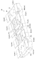
ソケット側保持金具34は、所定厚さの金属板をプレス成形することにより形成された保持金具板を折曲形成することによって形成することができ、コネクタ10の幅方向Yに延在する側板部34aと、側板部34aの下側を長手方向X中央側に向かって略直角に折曲した底板部34cとを備えている。そして、底板部34cの両端部をコネクタ10の幅方向Y両側から外側に突出させることで、固定端子34dとしての第1の固定端子34jが形成されている。   The socket side holding metal fitting 34 can be formed by bending a holding metal plate formed by press-molding a metal plate having a predetermined thickness, and the side plate portion extending in the width direction Y of the connector 10. 34a and a bottom plate portion 34c that is bent at a substantially right angle on the lower side of the side plate portion 34a toward the center in the longitudinal direction X. And the 1st fixed terminal 34j as the fixed terminal 34d is formed by making the both ends of the baseplate part 34c protrude outside from the width direction Y both sides of the connector 10. As shown in FIG.

側板部34aの幅方向Y両端部には、側板部34aの幅方向Y両端部をコネクタ10の長手方向X中央側に向かって略直角に折曲した延設部34bが形成されている。そして、この延設部34bの延在方向の終着部34gには下方に向かって延在して第1の回路基板60に半田70で固定される固定端子34dとしての第2の固定端子34kが設けられている。   At both ends in the width direction Y of the side plate portion 34 a, extending portions 34 b are formed by bending both ends in the width direction Y of the side plate portion 34 a toward the center in the longitudinal direction X of the connector 10. A second fixed terminal 34k as a fixed terminal 34d that extends downward and is fixed to the first circuit board 60 with solder 70 is provided at the end portion 34g in the extending direction of the extended portion 34b. Is provided.

本実施形態では、近傍に配置される第1の固定端子34jおよび第2の固定端子34kで形成される固定端子の組が、コネクタ10の一対の長辺のそれぞれの長手方向Xの両端に、ソケット側端子群G2と並設するように、合計4組設けられている。   In the present embodiment, a set of fixed terminals formed by the first fixed terminal 34j and the second fixed terminal 34k disposed in the vicinity is disposed at both ends in the longitudinal direction X of the pair of long sides of the connector 10, A total of four sets are provided so as to be juxtaposed with the socket-side terminal group G2.

このように、本実施形態では、ソケット側保持金具34が、第1の回路基板60上に固定される第1の固定端子34jと、当該第1の固定端子34jとは別に形成されて第1の回路基板60上に固定される第2の固定端子34kと、を有している。そして、この第2の固定端子34kがソケット側保持金具34の側板部34bから延出されている。   Thus, in the present embodiment, the socket-side holding metal fitting 34 is formed separately from the first fixed terminal 34j fixed on the first circuit board 60 and the first fixed terminal 34j. And a second fixed terminal 34k fixed on the circuit board 60. The second fixed terminal 34k extends from the side plate portion 34b of the socket side holding metal fitting 34.

このとき、第2の固定端子34kが、組となる第1の固定端子34jからのソケット側保持金具34上における道のり(ソケット側保持金具34の外面に沿った距離)が最大となる位置に設けられるようにしている。   At this time, the second fixed terminal 34k is provided at a position where the distance on the socket-side holding bracket 34 (distance along the outer surface of the socket-side holding bracket 34) from the paired first fixed terminal 34j is maximum. I am trying to do it.

また、本実施形態では、ソケット側保持金具34は、インサート成形によって、ソケットハウジング31に装着(配設)されている。このとき、ソケット側保持金具34の少なくとも一部がソケットハウジング31に沿って露出するようにしている。   In the present embodiment, the socket side holding metal fitting 34 is mounted (arranged) on the socket housing 31 by insert molding. At this time, at least a part of the socket-side holding metal fitting 34 is exposed along the socket housing 31.

すなわち、ソケット側保持金具34の少なくとも一部がソケットハウジング31の外面31sに沿って露出している。   That is, at least a part of the socket side holding metal fitting 34 is exposed along the outer surface 31 s of the socket housing 31.

さらに、本実施形態では、周壁部31bおよび板状壁部31aの外面31sの一部とソケット側保持金具34の外壁面34eの一部とが略面一の状態となるようにしている。換言すると、周壁部31bの外面31sにソケット側保持金具34の外壁面34eの一部が略面一の状態で露出するように、ソケットハウジング31にソケット側保持金具34が一体成形されている。   Further, in the present embodiment, a part of the outer surface 31s of the peripheral wall part 31b and the plate-like wall part 31a and a part of the outer wall surface 34e of the socket side holding metal fitting 34 are substantially flush with each other. In other words, the socket side holding metal fitting 34 is integrally formed with the socket housing 31 so that a part of the outer wall surface 34e of the socket side holding metal fitting 34 is substantially flush with the outer surface 31s of the peripheral wall portion 31b.

具体的には、側板部34aの外面34fの上部がソケットハウジング31のX方向(長手方向)最外端に延在する側面(長手方向の端面)31tに対して面一の状態で露出している。このように、本実施形態では、ソケット側保持金具34は、ソケットハウジング31の側面31tおよび底面31uのうち少なくともいずれか一方の面に沿って露出するようにしている。   Specifically, the upper part of the outer surface 34f of the side plate portion 34a is exposed in a flush manner with respect to the side surface (longitudinal end surface) 31t extending to the outermost end in the X direction (longitudinal direction) of the socket housing 31. Yes. Thus, in this embodiment, the socket side holding metal fitting 34 is exposed along at least one of the side surface 31t and the bottom surface 31u of the socket housing 31.

なお、底板部34cの外面34iは、ソケットハウジング31の底面31u(外面31s)に対して面一の状態でなく露出しているが、底板部34cの外面34iを、ソケットハウジング31の底面31u(外面31s)に対して面一の状態で露出させることも可能である。また、ソケット側保持金具34の外壁面34eは、周壁部31bの外面(短手方向壁部31iの側面31s)に露出させる必要はなく、また、露出させる場合であっても、周壁部31bの外面(短手方向壁部31iの側面31s)に対して面一の状態で露出させる必要はない。また、延設部34bの外壁面34e(外面34h)を周壁部31bの外面(長手方向壁部31hの側面31s)から露出させることも可能である。このとき、面一の状態で露出させてもよいし、面一の状態とならないように露出させてもよい。   Although the outer surface 34i of the bottom plate portion 34c is not flush with the bottom surface 31u (outer surface 31s) of the socket housing 31, the outer surface 34i of the bottom plate portion 34c is exposed to the bottom surface 31u ( It is also possible to expose the outer surface 31s) in a flush state. Further, the outer wall surface 34e of the socket-side holding metal fitting 34 does not need to be exposed to the outer surface of the peripheral wall portion 31b (the side surface 31s of the short-side wall portion 31i), and even if it is exposed, It is not necessary to expose the outer surface (the side surface 31s of the short-side wall portion 31i) in a flush state. It is also possible to expose the outer wall surface 34e (outer surface 34h) of the extending portion 34b from the outer surface of the peripheral wall portion 31b (the side surface 31s of the longitudinal wall portion 31h). At this time, it may be exposed in a flush state or may be exposed so as not to be in a flush state.

そして、図30および図32に示すように、ヘッダハウジング21の周壁部21bをソケットハウジング31の嵌合溝部31dに挿入して嵌合することで、ヘッダ20がソケット30に嵌合される。   30 and 32, the header 20 is fitted into the socket 30 by inserting and fitting the peripheral wall 21b of the header housing 21 into the fitting groove 31d of the socket housing 31.

なお、ヘッダ20をソケット30に嵌合させる際には、例えば、Y方向(幅方向:短手方向)一端側の長辺部分に形成されたテーパ部31eとテーパ部21dとを重ね合わせ、Y方向(幅方向:短手方向)他端側にずらしながら嵌合させるようにすることができる。こうすれば、テーパ部31eおよびテーパ部21dを誘い込み部として機能させることができ、より容易にヘッダ20をソケット30に嵌合させることができるようになる。   When the header 20 is fitted into the socket 30, for example, the taper portion 31e and the taper portion 21d formed on the long side portion on one end side in the Y direction (width direction: short direction) are overlapped, and Y It can be made to fit, shifting in the direction (width direction: short direction) other end side. If it carries out like this, the taper part 31e and the taper part 21d can be functioned as a lead-in part, and the header 20 can be more easily fitted now in the socket 30. FIG.

そして、ヘッダ20をソケット30に嵌合させた状態では、ソケット側信号用端子32の接点部R1およびヘッダ側信号用端子22の接点部R1が互いに接触することとなる。   In a state where the header 20 is fitted in the socket 30, the contact portion R1 of the socket-side signal terminal 32 and the contact portion R1 of the header-side signal terminal 22 come into contact with each other.

また、ソケット側信号用端子32の接点部R2およびヘッダ側信号用端子22の接点部R2が互いに接触することとなる。   Further, the contact portion R2 of the socket-side signal terminal 32 and the contact portion R2 of the header-side signal terminal 22 come into contact with each other.

そして、ソケット側電源用端子33の接点部R3およびヘッダ側電源用端子23の接点部R3が互いに接触することとなる。   Then, the contact portion R3 of the socket-side power supply terminal 33 and the contact portion R3 of the header-side power supply terminal 23 come into contact with each other.

また、ソケット側電源用端子33の接点部R4およびヘッダ側電源用端子23の接点部R4が互いに接触することとなる。   Further, the contact part R4 of the socket-side power supply terminal 33 and the contact part R4 of the header-side power supply terminal 23 come into contact with each other.

その結果、ソケット側信号用端子32とヘッダ側信号用端子22とが電気的に接続されるとともに、ソケット側電源用端子33とヘッダ側電源用端子23とが電気的に接続される。   As a result, the socket-side signal terminal 32 and the header-side signal terminal 22 are electrically connected, and the socket-side power supply terminal 33 and the header-side power supply terminal 23 are electrically connected.

こうして、第1の回路基板60の回路パターン61と第2の回路基板40の回路パターン41とが相互に電気的に接続されることとなる。   In this way, the circuit pattern 61 of the first circuit board 60 and the circuit pattern 41 of the second circuit board 40 are electrically connected to each other.

一方、ヘッダ20とソケット30とを離脱させる際には、これら両者を引き剥がし方向に抜去する。すると、段差状の係止部32dと段差状の被係止部22eとが相対摺動しつつ、ソケット側信号用端子32のばね部(32e,32f,32g,32h,32i,32j,32k,32m)が弾性変形し、係止部33dと被係止部32eとの係止が解除される。このとき、円弧状突起部32kの凹部22cへの嵌まり込みも解除される。   On the other hand, when the header 20 and the socket 30 are separated, both are removed in the peeling direction. Then, the stepped locking portion 32d and the stepped locked portion 22e slide relative to each other while the spring portions (32e, 32f, 32g, 32h, 32i, 32j, 32k, 32m) is elastically deformed, and the locking between the locking portion 33d and the locked portion 32e is released. At this time, the fitting of the arcuate protrusion 32k into the recess 22c is also released.

また、段差状の係止部33dと段差状の被係止部23eとが相対摺動しつつ、ソケット側電源用端子33のばね部(33e,33f,33g,33h,33i,33j,33k,33m)が弾性変形し、係止部33dと被係止部23eとの係止が解除される。このとき、円弧状突起部33kの凹部23cへの嵌まり込みも解除される。   Further, while the stepped locking portion 33d and the stepped locked portion 23e slide relative to each other, the spring portions (33e, 33f, 33g, 33h, 33i, 33j, 33k, 33m) is elastically deformed, and the locking between the locking portion 33d and the locked portion 23e is released. At this time, the fitting of the arcuate protrusion 33k into the recess 23c is also released.

こうして、ヘッダ20とソケット30とを分離させることができるようになる。   Thus, the header 20 and the socket 30 can be separated.

また、本実施形態では、上述したように、ヘッダハウジング21の長手方向X両端部にはヘッダ側保持金具24が、ソケットハウジング31の長手方向X両端部にはソケット側保持金具34が配設されている。このヘッダ側保持金具24およびソケット側保持金具340は、ヘッダハウジング21およびソケットハウジング31の強度を高めるとともに、上述した回路基板にそれぞれ取付固定するために用いられるものである。   In the present embodiment, as described above, the header side holding metal fittings 24 are arranged at both ends in the longitudinal direction X of the header housing 21, and the socket side holding metal fittings 34 are arranged at both ends in the longitudinal direction X of the socket housing 31. ing. The header-side holding metal fitting 24 and the socket-side holding metal fitting 340 are used to increase the strength of the header housing 21 and the socket housing 31 and to be attached and fixed to the circuit board described above.

本実施形態では、ヘッダ側保持金具24の固定端子24aを第2の回路基板40に半田付けすることで、ヘッダ20が第2の回路基板40に対して強固に結合されるようにしている。   In the present embodiment, the header 20 is firmly coupled to the second circuit board 40 by soldering the fixed terminals 24 a of the header-side holding metal fitting 24 to the second circuit board 40.

また、ソケット側保持金具34の固定端子34dを第1の回路基板60に半田付けすることで、ソケット30が第1の回路基板60に対して強固に結合されるようにしている。   Also, the socket 30 is firmly bonded to the first circuit board 60 by soldering the fixed terminals 34 d of the socket-side holding metal fitting 34 to the first circuit board 60.

このような構成によれば、各回路基板に強固に結合されたヘッダ20とソケット30とを相互に嵌合させることができる。これにより、ヘッダ側信号用端子22とソケット側信号用端子32とが接触導通するとともに、ヘッダ側電源用端子23とソケット側電源用端子33とが接触導通し、各回路基板の回路パターン同士を電気的に接続することができる。   According to such a configuration, the header 20 and the socket 30 firmly coupled to each circuit board can be fitted to each other. As a result, the header-side signal terminal 22 and the socket-side signal terminal 32 are brought into contact with each other, and the header-side power supply terminal 23 and the socket-side power supply terminal 33 are brought into contact with each other. Can be electrically connected.

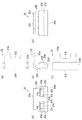
次に、図34から図37を参照しながら、各端子および各保持金具の回路パターンへの固定構造を説明する。なお、各端子および各保持金具の回路パターンへの固定構造は、図34から図37の構造に限定されるものではない。   Next, a structure for fixing each terminal and each holding metal fitting to the circuit pattern will be described with reference to FIGS. The structure for fixing each terminal and each holding metal fitting to the circuit pattern is not limited to the structure shown in FIGS.

ヘッダ側信号用端子22、ヘッダ側電源用端子23およびヘッダ側保持金具24は、図34に示すようにして、回路パターン41に固定されるようにすることができる。   The header-side signal terminal 22, the header-side power supply terminal 23, and the header-side holding metal fitting 24 can be fixed to the circuit pattern 41 as shown in FIG.

長手方向Xの中央部に配設されたヘッダ側信号用端子22は、付け根部22aが、それぞれ信号用の回路パターン41aに半田50で固定される。   The base portion 22a of the header-side signal terminal 22 disposed in the central portion in the longitudinal direction X is fixed to the signal circuit pattern 41a by the solder 50, respectively.

一方、長手方向Xの両側に配設されたヘッダ側電源用端子23は、付け根部23aが共通の回路パターン41bに半田50で固定される。そして、ヘッダ側保持金具24も、固定端子24aが共通の回路パターン41bに半田50で固定される。   On the other hand, the header-side power supply terminals 23 disposed on both sides in the longitudinal direction X are fixed to the circuit pattern 41b having a common base portion 23a with solder 50. And the header side holding metal fitting 24 is also fixed to the circuit pattern 41b with the fixed terminal 24a with the solder 50. FIG.

このように、図34では、固定端子24aと付け根部23aとが共通の回路パターン41bに半田付けされている。   As described above, in FIG. 34, the fixed terminal 24a and the base portion 23a are soldered to the common circuit pattern 41b.

さらに、図34では、隣り合うように配置されているヘッダ側電源用端子23とヘッダ側保持金具24とが共通の回路パターン41bに半田付けされている。すなわち、隣り合うように配置されているヘッダ側電源用端子23とヘッダ側保持金具24とが回路パターン41bを共用している。   Further, in FIG. 34, the header-side power supply terminal 23 and the header-side holding metal fitting 24 that are arranged adjacent to each other are soldered to a common circuit pattern 41b. That is, the header-side power supply terminal 23 and the header-side holding metal fitting 24 that are arranged adjacent to each other share the circuit pattern 41b.

したがって、長手方向Xの一側に配設された2つのヘッダ側電源用端子23は、長手方向Xの一側に配設された回路パターン41bおよび長手方向Xの一側に配設されたヘッダ側保持金具24を介して電気的に接続されている。また、長手方向Xの他側に配設された2つのヘッダ側電源用端子23も、長手方向Xの他側に配設された回路パターン41bおよび長手方向Xの他側に配設されたヘッダ側保持金具24を介して電気的に接続されている。   Accordingly, the two header-side power supply terminals 23 disposed on one side of the longitudinal direction X are composed of the circuit pattern 41b disposed on one side of the longitudinal direction X and the header disposed on one side of the longitudinal direction X. It is electrically connected through the side holding metal fitting 24. In addition, the two header-side power supply terminals 23 disposed on the other side of the longitudinal direction X are also provided with the circuit pattern 41b disposed on the other side of the longitudinal direction X and the header disposed on the other side of the longitudinal direction X. It is electrically connected through the side holding metal fitting 24.

一方、ソケット側信号用端子32、ソケット側電源用端子33およびソケット側保持金具34は、図35に示すようにして、回路パターン61に固定されるようにすることができる。   On the other hand, the socket-side signal terminal 32, the socket-side power supply terminal 33, and the socket-side holding metal fitting 34 can be fixed to the circuit pattern 61 as shown in FIG.

長手方向Xの中央部に配設されたソケット側信号用端子32は、付け根部32aが、それぞれ信号用の回路パターン61aに半田70で固定される。   The socket-side signal terminal 32 disposed at the center in the longitudinal direction X has a base portion 32a fixed to the signal circuit pattern 61a with solder 70, respectively.

長手方向Xの両側に配設されたソケット側電源用端子33は、付け根部33aが共通の回路パターン61bに半田70で固定される。そして、ソケット側保持金具34も、固定端子34dが共通の回路パターン61bに半田70で固定される。   The socket-side power supply terminals 33 arranged on both sides in the longitudinal direction X are fixed to the circuit pattern 61b having a common base portion 33a with solder 70. The socket-side holding metal fitting 34 is also fixed to the circuit pattern 61b having the fixed terminal 34d by the solder 70.

このように、図35では、固定端子34dと付け根部33aとが共通の回路パターン61bに半田付けされている。   As described above, in FIG. 35, the fixed terminal 34d and the base 33a are soldered to the common circuit pattern 61b.

さらに、図35では、隣り合うように配置されているソケット側電源用端子33とソケット側保持金具34とが共通の回路パターン61bに半田付けされている。したがって、長手方向Xの一側に配設された2つのソケット側電源用端子33は、長手方向Xの一側に配設された回路パターン61bおよび長手方向Xの一側に配設されたソケット側保持金具34を介して電気的に接続されている。また、長手方向Xの他側に配設された2つのソケット側電源用端子33も、長手方向Xの他側に配設された回路パターン61bおよび長手方向Xの他側に配設されたソケット側保持金具34を介して電気的に接続されている。   Further, in FIG. 35, the socket-side power supply terminals 33 and the socket-side holding metal fittings 34 arranged adjacent to each other are soldered to a common circuit pattern 61b. Accordingly, the two socket-side power supply terminals 33 disposed on one side of the longitudinal direction X are composed of the circuit pattern 61b disposed on one side of the longitudinal direction X and the socket disposed on one side of the longitudinal direction X. It is electrically connected via the side holding metal fitting 34. In addition, the two socket-side power supply terminals 33 disposed on the other side of the longitudinal direction X are also provided with the circuit pattern 61b disposed on the other side of the longitudinal direction X and the socket disposed on the other side of the longitudinal direction X. It is electrically connected via the side holding metal fitting 34.

さらに、本実施形態では、互いに組になる第1の固定端子34jおよび第2の固定端子34kが、付け根部33aが半田付けされる回路パターン61bに半田付けされている。   Furthermore, in the present embodiment, the first fixed terminal 34j and the second fixed terminal 34k that are paired with each other are soldered to the circuit pattern 61b to which the root portion 33a is soldered.

また、ヘッダ側信号用端子22、ヘッダ側電源用端子23およびヘッダ側保持金具24は、図36に示すようにして、回路パターン41に固定されるようにすることができる。   Further, the header-side signal terminal 22, the header-side power supply terminal 23, and the header-side holding metal fitting 24 can be fixed to the circuit pattern 41 as shown in FIG.

長手方向Xの中央部に配設されたヘッダ側信号用端子22は、付け根部22aが、それぞれ信号用の回路パターン41aに半田50で固定される。   The base portion 22a of the header-side signal terminal 22 disposed in the central portion in the longitudinal direction X is fixed to the signal circuit pattern 41a by the solder 50, respectively.

また、長手方向Xの両側に配設されたヘッダ側電源用端子23は、付け根部23aが電源用の回路パターン41cに半田50で固定される。   In addition, the header side power supply terminals 23 arranged on both sides in the longitudinal direction X are fixed at the base portion 23 a to the circuit pattern 41 c for power supply by the solder 50.

そして、ヘッダ側保持金具24は、固定端子24aが金具固定用の回路パターン41dに半田50で固定される。   In the header side holding metal fitting 24, the fixing terminal 24a is fixed to the circuit pattern 41d for metal fitting fixing with the solder 50.

このように、図36では、固定端子24aと付け根部23aとをそれぞれ別の回路パターン41に半田付けさせている。   In this way, in FIG. 36, the fixed terminal 24a and the base portion 23a are soldered to different circuit patterns 41, respectively.

一方、ソケット側信号用端子32、ソケット側電源用端子33およびソケット側保持金具34も、図37に示すようにして、回路パターン61に固定されるようにすることができる。   On the other hand, the socket-side signal terminal 32, the socket-side power supply terminal 33, and the socket-side holding metal fitting 34 can also be fixed to the circuit pattern 61 as shown in FIG.

長手方向Xの中央部に配設されたソケット側信号用端子32は、付け根部32aが、それぞれ信号用の回路パターン61aに半田70で固定される。   The socket-side signal terminal 32 disposed at the center in the longitudinal direction X has a base portion 32a fixed to the signal circuit pattern 61a with solder 70, respectively.

また、長手方向Xの両側に配設されたソケット側電源用端子33は、付け根部33aが電源用の回路パターン61cに半田70で固定される。   Further, the socket-side power supply terminals 33 arranged on both sides in the longitudinal direction X are fixed at the base portion 33a to the power supply circuit pattern 61c with solder 70.

そして、ソケット側保持金具34は、固定端子34dが金具固定用の回路パターン61dに半田70で固定される。   In the socket-side holding metal fitting 34, the fixing terminal 34d is fixed to the circuit pattern 61d for fixing the metal fitting with the solder 70.

このように、図37では、固定端子34dと付け根部33aとをそれぞれ別の回路パターン61に半田付けしている。   In this way, in FIG. 37, the fixed terminal 34d and the base 33a are soldered to different circuit patterns 61, respectively.

そして、ソケット側の固定構造として、図34と図36のいずれかを選択し、ヘッダ側の固定構造として、図35と図37のいずれかを選択し、それぞれを組み合わせることで、コネクタ10の回路パターンへの固定構造を得ることができる。   Then, either one of FIG. 34 and FIG. 36 is selected as the fixing structure on the socket side, and any one of FIG. 35 and FIG. A fixed structure to the pattern can be obtained.

以上、説明したように、本実施形態のコネクタ10は、ソケット側信号用端子32およびソケット側電源用端子33が配設される略矩形状のソケットハウジング31を有するソケット30と、ヘッダ側信号用端子22およびヘッダ側電源用端子23が配設される略矩形状のヘッダハウジング21を有するヘッダ20と、を備えている。   As described above, the connector 10 of the present embodiment includes the socket 30 having the substantially rectangular socket housing 31 in which the socket-side signal terminal 32 and the socket-side power supply terminal 33 are disposed, and the header-side signal. A header 20 having a substantially rectangular header housing 21 in which a terminal 22 and a header-side power supply terminal 23 are disposed.

そして、ソケット側信号用端子32およびソケット側電源用端子33が、ソケットハウジング31の長手方向Xに沿って配設されており、ソケット側電源用端子33よりもソケットハウジング31の長手方向Xの幅が狭いソケット側信号用端子32を有している。   The socket-side signal terminal 32 and the socket-side power supply terminal 33 are arranged along the longitudinal direction X of the socket housing 31, and the width of the socket housing 31 in the longitudinal direction X is larger than the socket-side power supply terminal 33. Has a narrow socket-side signal terminal 32.

こうすれば、互いに離間配置されている複数の端子を電源用端子として併用する場合に較べて、デッドスペースが形成されてしまうのが抑制されるため、ソケット30の長手方向Xを小型化することが可能になる。   In this case, since the formation of a dead space is suppressed as compared with the case where a plurality of terminals that are spaced apart from each other are used in combination, the longitudinal direction X of the socket 30 can be reduced in size. Is possible.

また、ソケット側信号用端子32の断面形状とソケット側電源用端子33の断面形状とが略同一形状をしている。その結果、部品加工性が向上するとともに組み立て加工性が向上する。   Further, the cross-sectional shape of the socket-side signal terminal 32 and the cross-sectional shape of the socket-side power supply terminal 33 are substantially the same. As a result, parts workability is improved and assembly workability is improved.

また、ソケットハウジング31には、当該ソケットハウジング31の長手方向Xに沿って配設されたソケット側信号用端子32およびソケット側電源用端子33で構成されるソケット側端子群G2が複数列配置されている。   The socket housing 31 has a plurality of rows of socket-side terminal groups G2 including socket-side signal terminals 32 and socket-side power supply terminals 33 arranged along the longitudinal direction X of the socket housing 31. ing.

こうすれば、端子の断面積を増加させることができるため、電流容量を増加させることができる。   By doing so, the cross-sectional area of the terminal can be increased, so that the current capacity can be increased.

また、ソケット側電源用端子33は、ヘッダ側電源用端子23に係止される段差状の係止部33dを有しており、係止部33dが、ソケット側電源用端子33におけるソケットハウジング31の長手方向Xの一端から他端にかけて形成されている。   Further, the socket-side power terminal 33 has a stepped locking part 33 d that is locked to the header-side power terminal 23, and the locking part 33 d is a socket housing 31 in the socket-side power terminal 33. Are formed from one end to the other end in the longitudinal direction X.

その結果、ロック力を向上させることができる上、挿抜を繰り返した際に摩耗しにくくなるため、製品の長寿命化を図ることが可能となる。   As a result, it is possible to improve the locking force, and it becomes difficult to wear when repeated insertion / extraction, so that it is possible to extend the life of the product.

また、ソケット側信号用端子32よりもソケットハウジング31の長手方向Xの外側に配設されるソケット側電源用端子33を有している。   In addition, the socket side power terminal 33 is provided outside the socket side signal terminal 32 in the longitudinal direction X of the socket housing 31.

こうすれば、発熱量の大きいソケット側電源用端子33をソケットハウジング31の長手方向Xの外側に配置されることになるため、放熱効率をより高めることができるようになる。   By doing so, the socket-side power supply terminal 33 having a large amount of heat generation is disposed outside the socket housing 31 in the longitudinal direction X, so that the heat radiation efficiency can be further improved.

また、ソケット側電源用端子33およびヘッダ側電源用端子23には、互いに接触する接点部R4が、ソケットハウジング31の長手方向Xに沿って複数設けられている。   The socket-side power supply terminal 33 and the header-side power supply terminal 23 are provided with a plurality of contact portions R4 that are in contact with each other along the longitudinal direction X of the socket housing 31.

こうすれば、端子の接触信頼性を向上させつつ、接触抵抗の低減を図ることができるようになる。   If it carries out like this, it will become possible to aim at reduction of contact resistance, improving the contact reliability of a terminal.

また、ソケット側電源用端子33には、複数の片部35,36が形成されており、複数の片部35,36のそれぞれに接点部R4が設けられている。   Further, the socket-side power supply terminal 33 is formed with a plurality of pieces 35 and 36, and a contact portion R4 is provided on each of the pieces 35 and 36.

こうすることで、端子の接触信頼性を向上させつつ、接触抵抗の低減を図ることができるようになる。   By doing so, the contact resistance can be reduced while improving the contact reliability of the terminal.

また、複数の片部35,36は、可撓性を有しており、それぞれ独立して撓むことが可能である。   Moreover, the some piece parts 35 and 36 have flexibility, and can be bent independently, respectively.

こうすることで、端子の接触信頼性をより向上させつつ、接触抵抗の低減を図ることができるようになる。   By doing so, the contact resistance can be reduced while further improving the contact reliability of the terminal.

また、ソケット側電源用端子33は、U字状部(33e,33f,33g,33h,33i,33j)を有している。このU字状部(33e,33f,33g,33h,33i,33j)の一端(33j側)には、接点部R4が設けられる自由端部(33k,33m)が連設されている。そして、複数の片部35,36が、少なくとも自由端部(33k,33m)に形成されている。   The socket-side power supply terminal 33 has U-shaped portions (33e, 33f, 33g, 33h, 33i, 33j). A free end portion (33k, 33m) provided with a contact portion R4 is connected to one end (33j side) of the U-shaped portion (33e, 33f, 33g, 33h, 33i, 33j). A plurality of pieces 35, 36 are formed at least at the free ends (33k, 33m).

こうすることで、端子の接触信頼性をより向上させることができるようになる。   By doing so, the contact reliability of the terminal can be further improved.

また、互いに接触するソケット側電源用端子33の接点部R4およびヘッダ側電源用端子23の接点部R4のうちいずれか一方の接点部(ヘッダ側電源用端子23の接点部R4)には凹部23cが形成されている。そして、他方の接点部(ソケット側電源用端子33の接点部R4)が凹部23cにおけるソケットハウジング31の長手方向X両端部(接点C1,C2)で接触する。   Further, one of the contact portions R4 of the socket-side power supply terminal 33 and the contact portion R4 of the header-side power supply terminal 23 that are in contact with each other (the contact portion R4 of the header-side power supply terminal 23) has a recess 23c. Is formed. The other contact portion (contact portion R4 of the socket-side power supply terminal 33) contacts at both ends (contacts C1, C2) in the longitudinal direction X of the socket housing 31 in the recess 23c.

こうすることで、端子の接触信頼性をより向上させることができるようになる。   By doing so, the contact reliability of the terminal can be further improved.

また、ソケットハウジング31には、ソケット側保持金具34が配設されており、ソケット側保持金具34の少なくとも一部(34a,34c)がソケットハウジング31の外面31sに沿って露出している。   Further, the socket housing 31 is provided with a socket side holding metal fitting 34, and at least a part (34 a, 34 c) of the socket side holding metal fitting 34 is exposed along the outer surface 31 s of the socket housing 31.

こうすることで、ソケットハウジングの小型化を図りつつ、ソケットハウジングとソケット側保持金具とをより強固に固定することができる。   By doing so, it is possible to more firmly fix the socket housing and the socket side holding metal fitting while reducing the size of the socket housing.

さらに、ソケット側保持金具34は、ソケットハウジング31の側面31tおよび底面31uのうち少なくともいずれか一方の面に沿って露出している。   Furthermore, the socket side holding metal fitting 34 is exposed along at least one of the side surface 31 t and the bottom surface 31 u of the socket housing 31.

したがって、ソケットハウジングの小型化を図りつつ、ソケットハウジングとソケット側保持金具とをより一層強固に固定することができるようになる。   Therefore, the socket housing and the socket side holding metal fitting can be more firmly fixed while reducing the size of the socket housing.

また、ソケット側保持金具34がインサート成形によってソケットハウジング31に配設されている。   Moreover, the socket side holding | maintenance metal fitting 34 is arrange | positioned by the socket housing 31 by insert molding.

その結果、ソケットハウジングとソケット側保持金具とをより強固に固定することができる上、圧入した場合に較べて、ソケットハウジングとの接触面積を増加させることができるため、放熱性を高めることができるようになる。   As a result, it is possible to more firmly fix the socket housing and the socket-side holding metal fitting, and it is possible to increase the contact area with the socket housing as compared with the case where the socket housing is press-fitted. It becomes like this.

また、ソケット側保持金具34は、第1の回路基板60に形成された回路パターン61に半田付けされる固定端子34dを有している。そして、ソケット側電源用端子33は、第1の回路基板60に形成された回路パターン61に半田付けされる付け根部33aを有している。そして、固定端子34dと付け根部33aとが共通の回路パターン61bに半田付けされている。 In addition, the socket side holding metal fitting 34 has a fixed terminal 34 d to be soldered to the circuit pattern 61 formed on the first circuit board 60. The socket-side power supply terminal 33 has a root portion 33 a that is soldered to the circuit pattern 61 formed on the first circuit board 60. The fixed terminal 34d and the base 33a are soldered to the common circuit pattern 61b.

こうすれば、ソケット側保持金具34が固定される回路パターンも、ソケット側電源用端子33が発する熱の放熱板として利用することができ、放熱性をより高めることができるようになる。   In this way, the circuit pattern to which the socket-side holding metal fitting 34 is fixed can also be used as a heat radiating plate for the heat generated by the socket-side power supply terminal 33, and the heat dissipation can be further improved.

また、ソケット側保持金具34とソケット側電源用端子33とが隣り合うように配置されている。   Moreover, the socket side holding | maintenance metal fitting 34 and the socket side power supply terminal 33 are arrange | positioned so that it may adjoin.

こうすれば、放熱性を高めることができる上、回路パターンの配線形状が複雑化してしまうのを抑制することができるようになる。   By doing so, it is possible to improve heat dissipation and to suppress the wiring shape of the circuit pattern from becoming complicated.

また、固定端子34dは、第1の固定端子34jと、当該第1の固定端子34jとは別に形成される第2の固定端子34kと、を有している。   The fixed terminal 34d includes a first fixed terminal 34j and a second fixed terminal 34k formed separately from the first fixed terminal 34j.

したがって、ソケット側保持金具34と第1の回路基板60とをより強固に固定することができるようになる。   Therefore, the socket side holding metal fitting 34 and the first circuit board 60 can be more firmly fixed.

このとき、第1の固定端子34jおよび第2の固定端子34kが、付け根部33aが半田付けされる回路パターン61bに半田付けされるようにすれば、放熱効果をさらに向上させることができるようになる。   At this time, if the first fixed terminal 34j and the second fixed terminal 34k are soldered to the circuit pattern 61b to which the base portion 33a is soldered, the heat dissipation effect can be further improved. Become.

また、ヘッダ側信号用端子22およびヘッダ側電源用端子23が、ヘッダハウジング21の長手方向Xに沿って配設されており、ヘッダ側電源用端子23よりもヘッダハウジング21の長手方向Xの幅が狭いヘッダ側信号用端子22を有している。   Further, the header-side signal terminal 22 and the header-side power supply terminal 23 are arranged along the longitudinal direction X of the header housing 21, and the width in the longitudinal direction X of the header housing 21 is larger than the header-side power supply terminal 23. Has a narrow header-side signal terminal 22.

こうすれば、互いに離間配置されている複数の端子を電源用端子として併用する場合に較べて、デッドスペースが形成されてしまうのが抑制されるため、ヘッダ20の長手方向Xを小型化することが可能になる。   In this case, since the formation of a dead space is suppressed as compared with the case where a plurality of terminals that are spaced apart from each other are used together as a power supply terminal, the longitudinal direction X of the header 20 can be reduced in size. Is possible.

また、ヘッダ側信号用端子22の断面形状とヘッダ側電源用端子23の断面形状とが略同一形状をしているため、部品加工性が向上するとともに組み立て加工性が向上する。   In addition, since the cross-sectional shape of the header-side signal terminal 22 and the cross-sectional shape of the header-side power supply terminal 23 are substantially the same shape, the component workability is improved and the assembly workability is improved.

また、ヘッダハウジング21には、当該ヘッダハウジング21の長手方向Xに沿って配設されたヘッダ側信号用端子22およびヘッダ側電源用端子23で構成されるヘッダ側端子群G1が複数列配置されている。   The header housing 21 includes a plurality of rows of header-side terminal groups G1 including header-side signal terminals 22 and header-side power supply terminals 23 disposed along the longitudinal direction X of the header housing 21. ing.

その結果、端子の断面積を増加させることができるため、電流容量を増加させることができる。   As a result, since the cross-sectional area of the terminal can be increased, the current capacity can be increased.

また、ヘッダ側電源用端子23は、ソケット側電源用端子33に係止される段差状の被係止部23eを有しており、被係止部23eが、ヘッダ側電源用端子23におけるヘッダハウジング21の長手方向Xの一端から他端にかけて形成されている。   The header-side power supply terminal 23 has a stepped locked portion 23e that is locked to the socket-side power supply terminal 33, and the locked portion 23e is a header in the header-side power supply terminal 23. The housing 21 is formed from one end to the other end in the longitudinal direction X.

その結果、ロック力を向上させることができる上、挿抜を繰り返した際に摩耗しにくくなるため、製品の長寿命化を図ることが可能となる。   As a result, it is possible to improve the locking force, and it becomes difficult to wear when repeated insertion / extraction, so that it is possible to extend the life of the product.

また、ヘッダ側信号用端子22よりもヘッダハウジング21の長手方向Xの外側に配設されるヘッダ側電源用端子23を有している。このように、発熱量の大きいヘッダ側電源用端子をヘッダハウジングの長手方向外側に配置することで、放熱性を高めることができるようになる。   In addition, the header side power terminal 23 is disposed outside the header side signal terminal 22 in the longitudinal direction X of the header housing 21. Thus, by disposing the header-side power supply terminal with a large amount of heat generation on the outer side in the longitudinal direction of the header housing, it is possible to improve the heat dissipation.

また、ヘッダハウジング21には、ヘッダ側保持金具24が配設されている。そして、ヘッダ側保持金具24は、第2の回路基板40に形成された回路パターン41に半田付けされる固定端子24aを有している。また、ヘッダ側電源用端子23は、第2の回路基板40に形成された回路パターン41に半田付けされる付け根部23aを有している。そして、固定端子24aと付け根部23aとが共通の回路パターン41bに半田付けされている。   The header housing 21 is provided with a header side holding metal fitting 24. The header holding metal 24 has a fixed terminal 24 a that is soldered to a circuit pattern 41 formed on the second circuit board 40. The header-side power supply terminal 23 has a base portion 23 a that is soldered to the circuit pattern 41 formed on the second circuit board 40. The fixed terminal 24a and the base portion 23a are soldered to the common circuit pattern 41b.

こうすれば、ヘッダ側保持金具24が固定される回路パターンも、ヘッダ側電源用端子23が発する熱の放熱板として利用することができ、放熱性をより高めることができるようになる。   By doing this, the circuit pattern to which the header side holding metal fitting 24 is fixed can also be used as a heat radiating plate for the heat generated by the header side power supply terminal 23, and the heat dissipation can be further improved.

また、ヘッダ側保持金具24とヘッダ側電源用端子23とが隣り合うように配置されている。   Further, the header side holding metal fitting 24 and the header side power supply terminal 23 are arranged so as to be adjacent to each other.

こうすれば、放熱性を高めることができる上、回路パターンの配線形状が複雑化してしまうのを抑制することができるようになる。   By doing so, it is possible to improve heat dissipation and to suppress the wiring shape of the circuit pattern from becoming complicated.

以上、本発明の好適な実施形態について説明したが、本発明は上記実施形態には限定されず、種々の変形が可能である。   The preferred embodiments of the present invention have been described above. However, the present invention is not limited to the above embodiments, and various modifications can be made.

例えば、上記実施形態では、ヘッダ20が、平面視で当該ヘッダ20の中心に対して点対称となるように形成されているとともに、ソケット30が、平面視で当該ソケット30の中心に対して点対称となるように形成されているもの(極性がないコネクタ)を例示した。   For example, in the above embodiment, the header 20 is formed so as to be point-symmetric with respect to the center of the header 20 in plan view, and the socket 30 is pointed with respect to the center of the socket 30 in plan view. The thing formed so that it might become symmetrical (connector without polarity) was illustrated.

しかしながら、極性を有するコネクタ(180度回転させた際に、同一の形状とならないようにしたコネクタ)に本発明を適用することも可能である。   However, it is also possible to apply the present invention to a connector having polarity (a connector that does not have the same shape when rotated 180 degrees).

また、ヘッダ20とソケット30とを嵌合させた状態で、ヘッダ側保持金具とソケット側保持金具とが係合する構成とすることも可能である。   Moreover, it is also possible to employ a configuration in which the header side holding metal fitting and the socket side holding metal fitting are engaged in a state where the header 20 and the socket 30 are fitted.

また、ソケットハウジングやヘッダハウジング、その他細部のスペック(形状、大きさ、レイアウト等)も適宜に変更可能である。 Also, socket Toja Ujingu and header roof Ujingu, other details of the specifications (shape, size, layout, etc.) can also be changed as appropriate.

10 コネクタ
20 ヘッダ
21 ヘッダハウジング
22 ヘッダ側信号用端子
22a 付け根部
22c 凹部
22e 被係止部
23 ヘッダ側電源用端子
23a 付け根部
23c 凹部
23e 被係止部
24 ヘッダ側保持金具
24a 固定端子
30 ソケット
31 ソケットハウジング
31s 外面
31t 側面
31u 底面
32 ソケット側信号用端子
32a 付け根部
33 ソケット側電源用端子
33a 付け根部
35 片部
36 片部
34 ソケット側保持金具
34d 固定端子
34j 第1の固定端子
34k 第2の固定端子
34e 外壁面
34f 外面
40 第2の回路基板
41 回路パターン
50 半田
60 第1の回路基板
61 回路パターン
70 半田
R1〜R5 接点部
C1、C2 接点
X 長手方向
Y 短手方向(幅方向)
Z 上下方向
10 connector 20 header 21 header roof Ujingu 22 header-side signal terminal 22a base portion 22c recess 22e stopped portion 23 header-side power supply terminal 23a base portion 23c recess 23e locked portion 24 header-side holding metal fitting 24a fixed terminal 30 socket 31 socket Toja Ujingu 31s outer surface 31t side 31u bottom 32 socket-side signal terminal 32a base portion 33 socket side power terminal 33a base portion 35 arm portion 36 arm portion 34 socket-side holding metal fitting 34d fixed terminal 34j first fixed terminal 34k first 2 fixed terminal 34e outer wall surface 34f outer surface 40 second circuit board 41 circuit pattern 50 solder 60 first circuit board 61 circuit pattern 70 solder R1 to R5 contact part C1, C2 contact X longitudinal direction Y short direction (width direction) )
Z Vertical direction

Claims (8)

ソケット側信号用端子およびソケット側電源用端子が配設される略矩形状のソケットハウジングを有するソケットと、ヘッダ側信号用端子およびヘッダ側電源用端子が配設される略矩形状のヘッダハウジングを有するヘッダと、を備え、前記ソケットハウジングと前記ヘッダハウジングとを嵌合させることで、前記ソケット側信号用端子と前記ヘッダ側信号用端子とが接触するとともに、前記ソケット側電源用端子と前記ヘッダ側電源用端子とが接触するコネクタであって、
前記ソケットハウジングには、側板部と、前記側板部から前記ソケットハウジングの長手方向の内側に延設されるとともに、板厚方向が回路基板の表面と交差する方向となる底板部と、を有するソケット側保持金具が配設されており、
前記ソケット側保持金具は、前記回路基板に形成された回路パターンに半田付けされる固定端子を有しており、
前記ソケット側電源用端子は、前記回路基板に形成された回路パターンに半田付けされる付け根部を有しており、
前記固定端子と前記付け根部とが共通の回路パターンに半田付けされており、
前記固定端子は、前記底板部から延設される第1の固定端子と、前記側板部から延設され、当該第1の固定端子とは別に形成される第2の固定端子と、を有しており、
互いに近傍に配置される前記第1の固定端子と前記第2の固定端子とで形成される固定端子の組が2組形成されていることを特徴とするコネクタ。
A socket having a substantially rectangular socket housing in which socket-side signal terminals and socket-side power supply terminals are disposed; and a substantially rectangular header housing in which header-side signal terminals and header-side power supply terminals are disposed. And the socket-side signal terminal and the header-side signal terminal are brought into contact with each other by fitting the socket housing and the header housing together, and the socket-side power supply terminal and the header. A connector that contacts the power supply terminal
The socket housing includes a side plate portion, and a bottom plate portion that extends from the side plate portion inward in the longitudinal direction of the socket housing and has a plate thickness direction that intersects the surface of the circuit board. Side holding brackets are arranged,
The socket-side holding metal fitting has a fixing pin which is soldered to the circuit pattern formed on the circuit board,
The socket side power supply terminal has a root portion soldered to a circuit pattern formed on the circuit board,
The fixed terminal and the base are soldered to a common circuit pattern,
The fixed terminal includes a first fixed terminal extending from the bottom plate portion, and a second fixed terminal extending from the side plate portion and formed separately from the first fixed terminal. And
2. A connector comprising two sets of fixed terminals formed by the first fixed terminal and the second fixed terminal arranged in the vicinity of each other.
前記ソケット側保持金具と前記ソケット側電源用端子とが隣り合うように配置されていることを特徴とする請求項1に記載のコネクタ。   The connector according to claim 1, wherein the socket-side holding metal fitting and the socket-side power supply terminal are arranged adjacent to each other. 前記ソケット側保持金具の少なくとも一部が前記ソケットハウジングの外面に沿って露出していることを特徴とする請求項1または請求項2に記載のコネクタ。   The connector according to claim 1, wherein at least a part of the socket side holding metal fitting is exposed along an outer surface of the socket housing. 前記ソケット側保持金具は、前記ソケットハウジングの側面および底面のうち少なくともいずれか一方の面に沿って露出していることを特徴とする請求項3に記載のコネクタ。   The connector according to claim 3, wherein the socket side holding metal fitting is exposed along at least one of a side surface and a bottom surface of the socket housing. 前記ソケット側保持金具がインサート成形によって前記ソケットハウジングに配設されていることを特徴とする請求項1〜4のうちいずれか1項に記載のコネクタ。   The connector according to claim 1, wherein the socket side holding metal fitting is disposed in the socket housing by insert molding. 前記第1の固定端子および前記第2の固定端子が、前記付け根部が半田付けされる回路パターンに半田付けされていることを特徴とする請求項1〜5のうちいずれか1項に記載のコネクタ。   6. The device according to claim 1, wherein the first fixed terminal and the second fixed terminal are soldered to a circuit pattern to which the base portion is soldered. connector. ソケット側信号用端子およびソケット側電源用端子が配設される略矩形状のソケットハウジングを有するソケットと、ヘッダ側信号用端子およびヘッダ側電源用端子が配設される略矩形状のヘッダハウジングを有するヘッダと、を備え、前記ソケットハウジングと前記ヘッダハウジングとを嵌合させることで、前記ソケット側信号用端子と前記ヘッダ側信号用端子とが接触するとともに、前記ソケット側電源用端子と前記ヘッダ側電源用端子とが接触するコネクタであって、
前記ソケットハウジングには、側板部と、前記側板部から前記ソケットハウジングの長手方向の内側に延設されるとともに、板厚方向が第1の回路基板の表面と交差する方向となる底板部と、を有するソケット側保持金具が配設されており、
前記ソケット側保持金具は、前記第1の回路基板に形成された回路パターンに半田付けされる固定端子を有しており、
前記ソケット側電源用端子は、前記第1の回路基板に形成された回路パターンに半田付けされる付け根部を有しており、
前記固定端子と前記ソケット側電源用端子の付け根部とが、前記第1の回路基板に形成された共通の回路パターンに半田付けされており、
前記ヘッダハウジングには、ヘッダ側保持金具が配設されており、
前記ヘッダ側保持金具は、第2の回路基板に形成された回路パターンに半田付けされる固定端子を有しており、
前記ヘッダ側電源用端子は、前記第2の回路基板に形成された回路パターンに半田付けされる付け根部を有しており、
前記固定端子と前記ヘッダ側電源用端子の付け根部とが、前記第2の回路基板に形成された共通の回路パターンに半田付けされており、
前記ソケット側保持金具の固定端子は、前記底板部から延設される第1の固定端子と、前記側板部から延設され、当該第1の固定端子とは別に形成される第2の固定端子と、を有しており、
互いに近傍に配置される前記第1の固定端子と前記第2の固定端子とで形成される固定端子の組が2組形成されていることを特徴とするコネクタ。
A socket having a substantially rectangular socket housing in which socket-side signal terminals and socket-side power supply terminals are disposed; and a substantially rectangular header housing in which header-side signal terminals and header-side power supply terminals are disposed. And the socket-side signal terminal and the header-side signal terminal are brought into contact with each other by fitting the socket housing and the header housing together, and the socket-side power supply terminal and the header. A connector that contacts the power supply terminal
The socket housing includes a side plate portion, a bottom plate portion that extends from the side plate portion inward in the longitudinal direction of the socket housing, and whose plate thickness direction intersects the surface of the first circuit board. A socket side holding bracket having
The socket-side holding metal fitting has a fixing pin which is soldered to the circuit pattern formed on the first circuit board,
The socket side power supply terminal has a base portion soldered to a circuit pattern formed on the first circuit board,
The fixed terminal and the base of the socket-side power supply terminal are soldered to a common circuit pattern formed on the first circuit board,
The header housing is provided with a header side holding bracket,
The header side holding metal fitting has a fixed terminal soldered to a circuit pattern formed on the second circuit board,
The header side power supply terminal has a base portion soldered to a circuit pattern formed on the second circuit board,
The fixed terminal and the base portion of the header-side power terminal are soldered to a common circuit pattern formed on the second circuit board,
The fixed terminal of the socket side holding metal fitting is a first fixed terminal extending from the bottom plate portion, and a second fixed terminal extending from the side plate portion and formed separately from the first fixed terminal. And
2. A connector comprising two sets of fixed terminals formed by the first fixed terminal and the second fixed terminal arranged in the vicinity of each other.
請求項1〜7のうちいずれか1項に記載のコネクタに用いられるソケット。   The socket used for the connector of any one of Claims 1-7.
JP2014161129A 2014-08-07 2014-08-07 Connector and socket used for the connector Active JP6473990B2 (en)

Priority Applications (7)

Application Number Priority Date Filing Date Title
JP2014161129A JP6473990B2 (en) 2014-08-07 2014-08-07 Connector and socket used for the connector
US15/314,576 US9843117B2 (en) 2014-08-07 2015-08-03 Connector, and header and socket which are used in connector
PCT/JP2015/003896 WO2016021177A1 (en) 2014-08-07 2015-08-03 Connector and header and socket used in said connector
CN201580031833.7A CN106663888B (en) 2014-08-07 2015-08-03 Connector and the plug piece and socket piece used in the connector
EP15828990.0A EP3179568B1 (en) 2014-08-07 2015-08-03 Connector and header and socket used in said connector
CN201910466241.8A CN110165446B (en) 2014-08-07 2015-08-03 Socket piece
US15/808,678 US10305205B2 (en) 2014-08-07 2017-11-09 Connector, and header and socket which are used in connector

Applications Claiming Priority (1)

Application Number Priority Date Filing Date Title
JP2014161129A JP6473990B2 (en) 2014-08-07 2014-08-07 Connector and socket used for the connector

Related Child Applications (1)

Application Number Title Priority Date Filing Date
JP2018213132A Division JP6643641B2 (en) 2018-11-13 2018-11-13 Connector, socket and connection structure between socket and circuit board

Publications (3)

Publication Number Publication Date
JP2016039017A JP2016039017A (en) 2016-03-22
JP2016039017A5 JP2016039017A5 (en) 2017-02-16
JP6473990B2 true JP6473990B2 (en) 2019-02-27

Family

ID=55263472

Family Applications (1)

Application Number Title Priority Date Filing Date
JP2014161129A Active JP6473990B2 (en) 2014-08-07 2014-08-07 Connector and socket used for the connector

Country Status (5)

Country Link
US (2) US9843117B2 (en)
EP (1) EP3179568B1 (en)
JP (1) JP6473990B2 (en)
CN (2) CN106663888B (en)
WO (1) WO2016021177A1 (en)

Families Citing this family (8)

* Cited by examiner, † Cited by third party
Publication number Priority date Publication date Assignee Title
JP6712799B2 (en) * 2016-02-05 2020-06-24 パナソニックIpマネジメント株式会社 Connector and header and socket used for the connector
JP6512210B2 (en) * 2016-12-21 2019-05-15 第一精工株式会社 Connector device
JP6894320B2 (en) * 2017-08-21 2021-06-30 ヒロセ電機株式会社 Electrical connector for circuit board
JP1625950S (en) * 2018-06-22 2019-03-04
KR102606247B1 (en) * 2018-07-30 2023-11-27 삼성전자주식회사 A connector including a support portion for supporting at least a portion of a conductive pin and an electronic device including the same
JP7411882B2 (en) * 2019-08-08 2024-01-12 パナソニックIpマネジメント株式会社 connector
JP1656956S (en) * 2019-11-11 2020-04-06
JP1656955S (en) * 2019-11-11 2020-04-06

Family Cites Families (16)

* Cited by examiner, † Cited by third party
Publication number Priority date Publication date Assignee Title
US5685729A (en) * 1995-06-02 1997-11-11 General Motors Corporation Electrical connector and vent tube assembly with connector position assurance
JP3423560B2 (en) 1996-05-29 2003-07-07 ケル株式会社 connector
JP2005019144A (en) 2003-06-25 2005-01-20 Matsushita Electric Works Ltd Connector
JP2005294034A (en) * 2004-03-31 2005-10-20 Matsushita Electric Works Ltd Connector
JP4219308B2 (en) * 2004-08-18 2009-02-04 ヒロセ電機株式会社 Reinforcing bracket with lock function and connector provided with the same
JP2008270085A (en) * 2007-04-24 2008-11-06 Matsushita Electric Works Ltd Connector
JP5623694B2 (en) 2008-05-12 2014-11-12 オムロン株式会社 connector
SG166707A1 (en) * 2009-06-03 2010-12-29 3M Innovative Properties Co Connector
JP5807181B2 (en) 2011-02-07 2015-11-10 パナソニックIpマネジメント株式会社 Holding bracket, connector connector and connector
JP2013101909A (en) * 2011-10-14 2013-05-23 Molex Inc Connector
CN103050805B (en) * 2011-10-14 2014-12-10 莫列斯公司 Connector
JP5638026B2 (en) * 2012-05-01 2014-12-10 ヒロセ電機株式会社 Electrical connector assembly
JP6245964B2 (en) 2013-12-02 2017-12-13 モレックス エルエルシー connector
JP5887326B2 (en) * 2013-12-12 2016-03-16 モレックス エルエルシー connector
KR20150084563A (en) * 2014-01-14 2015-07-22 삼성디스플레이 주식회사 Connector assembly and display apparatus having the same
US9420658B2 (en) * 2014-12-05 2016-08-16 Xenio Corporation Inrush energy control for a light emitter

Also Published As

Publication number Publication date
EP3179568B1 (en) 2020-03-11
CN106663888B (en) 2019-06-28
WO2016021177A1 (en) 2016-02-11
US10305205B2 (en) 2019-05-28
JP2016039017A (en) 2016-03-22
US20180069332A1 (en) 2018-03-08
CN110165446A (en) 2019-08-23
US9843117B2 (en) 2017-12-12
EP3179568A1 (en) 2017-06-14
EP3179568A4 (en) 2017-07-26
US20170194727A1 (en) 2017-07-06
CN106663888A (en) 2017-05-10
CN110165446B (en) 2021-07-09

Similar Documents

Publication Publication Date Title
JP6473990B2 (en) Connector and socket used for the connector
JP6388152B2 (en) Connector and header and socket used for the connector
JP6712794B2 (en) Connector and header and socket used for the connector
WO2017134719A1 (en) Connector, as well as head and socket used for said connector
TWI445252B (en) Card edge connector
WO2017187993A1 (en) Connector, header, and socket
JP4805422B1 (en) connector
JP6681577B2 (en) Connector and header and socket used for the connector
JP2019021651A (en) Connector and socket
WO2017187992A1 (en) Retainer, connector connection body, and connector
JP7300632B2 (en) Connector splice and connector
JP7033737B2 (en) Connector connectors and connectors
US7749000B1 (en) Electrical connector
US7476109B2 (en) Electrical connector assembled with a bondable element

Legal Events

Date Code Title Description
A521 Request for written amendment filed

Free format text: JAPANESE INTERMEDIATE CODE: A523

Effective date: 20170111

A621 Written request for application examination

Free format text: JAPANESE INTERMEDIATE CODE: A621

Effective date: 20170605

A131 Notification of reasons for refusal

Free format text: JAPANESE INTERMEDIATE CODE: A131

Effective date: 20180227

A521 Request for written amendment filed

Free format text: JAPANESE INTERMEDIATE CODE: A523

Effective date: 20180501

A02 Decision of refusal

Free format text: JAPANESE INTERMEDIATE CODE: A02

Effective date: 20180814

A521 Request for written amendment filed

Free format text: JAPANESE INTERMEDIATE CODE: A523

Effective date: 20181113

A911 Transfer to examiner for re-examination before appeal (zenchi)

Free format text: JAPANESE INTERMEDIATE CODE: A911

Effective date: 20181120

TRDD Decision of grant or rejection written
A01 Written decision to grant a patent or to grant a registration (utility model)

Free format text: JAPANESE INTERMEDIATE CODE: A01

Effective date: 20190115

A61 First payment of annual fees (during grant procedure)

Free format text: JAPANESE INTERMEDIATE CODE: A61

Effective date: 20190118

R151 Written notification of patent or utility model registration

Ref document number: 6473990

Country of ref document: JP

Free format text: JAPANESE INTERMEDIATE CODE: R151