JP6473286B2 - Packaging box - Google Patents
Packaging box Download PDFInfo
- Publication number
- JP6473286B2 JP6473286B2 JP2013114304A JP2013114304A JP6473286B2 JP 6473286 B2 JP6473286 B2 JP 6473286B2 JP 2013114304 A JP2013114304 A JP 2013114304A JP 2013114304 A JP2013114304 A JP 2013114304A JP 6473286 B2 JP6473286 B2 JP 6473286B2
- Authority
- JP
- Japan
- Prior art keywords
- buffer
- packaging box
- flap
- wall
- toner cartridge
- Prior art date
- Legal status (The legal status is an assumption and is not a legal conclusion. Google has not performed a legal analysis and makes no representation as to the accuracy of the status listed.)
- Active
Links
Images


Landscapes
- Cartons (AREA)
Description
本発明は、トナーカートリッジ等の被収容物を収容する包装箱に関する。 The present invention relates to a packaging box that accommodates an object such as a toner cartridge.
この種の包装箱では、被収容物を保護するために、緩衝部材を用いることがある。例えば、トナーカートリッジは、カートリッジ本体の外側に設けられた駆動用のギアやシャッター等を有しているため、トナーカートリッジを包装箱に収容するだけではなく、緩衝部材によりギアやシャッター等を保護する必要がある。 In this type of packaging box, a buffer member may be used to protect the object to be contained. For example, since the toner cartridge has a driving gear, a shutter, and the like provided outside the cartridge body, the toner cartridge is not only housed in the packaging box, but the gear, the shutter, and the like are protected by a buffer member. There is a need.
特許文献1〜4では、トナーカートリッジの両端部にそれぞれの緩衝部材を嵌合させて、トナーカートリッジを各緩衝部材と共に包装箱に収納しており、衝撃等が包装箱に作用しても、衝撃等が各緩衝部材で吸収されてトナーカートリッジに殆ど及ばないようにしている。緩衝部材としては、パルプモールドや発泡スチロールなどの成形品、あるいはダンボールを別途組み立てたもの等が用いられることが多い。
In
しかしながら、包装箱とは別に、パルプモールドや発泡スチロールなどの成形品を緩衝部材として用いる場合は、部材の種類や個数が多くなり、コストが高くなる。また、ダンボールを別途組み立てたものを緩衝部材として用いる場合は、コストを抑えることができても、部材の種類や個数が低減されるわけではない。一方、近年、資源の節減や廃棄物の低減が促進されつつあるので、包装箱についても部材の種類や個数を低減させるのが望ましい。 However, when a molded product such as a pulp mold or a polystyrene foam is used as a buffer member separately from the packaging box, the number and type of members increase and the cost increases. In addition, when a separately assembled cardboard is used as a buffer member, the type and number of members are not reduced even if the cost can be reduced. On the other hand, in recent years, resource saving and waste reduction are being promoted, so it is desirable to reduce the type and number of members of the packaging box.
そこで、本発明は、上記従来の問題点に鑑みなされたものであり、緩衝部材を別途用意する必要がなく、緩衝部材が一体化された包装箱を提供することを目的とする。 Accordingly, the present invention has been made in view of the above-described conventional problems, and an object thereof is to provide a packaging box in which the buffer member is integrated without the need for separately preparing the buffer member.
上記課題を解決するために、本発明の包装箱は、被収容物を囲む複数の壁部を備えた包装箱であって、前記各壁部のいずれかに連接された緩衝用フラップと、前記緩衝用フラップが連接された前記壁部に対向する他の壁部に連接された押圧用フラップとを備え、前記緩衝用フラップを前記包装箱の内側に折り込むことにより前記被収容物を保護する緩衝部を形成し、前記押圧用フラップを前記包装箱の内側に折り込むことにより形成されて、前記被収容物を前記緩衝部の側に押圧する押圧部を設け、前記押圧部および前記緩衝部は、連接した壁部から離間して、前記被収容物の端部に当接し、前記押圧用フラップの山折りにされた折り目線を前記被収容物の一方の端部に接触させ、前記緩衝用フラップの折り目線で区画された平面である区画部を前記被収容物の他方の端部に接触させることを特徴とする。 In order to solve the above-mentioned problem, the packaging box of the present invention is a packaging box having a plurality of wall portions surrounding an object to be contained, and a buffering flap connected to any one of the wall portions, And a pressing flap connected to the other wall portion facing the wall portion connected to the buffering flap, and the buffer for protecting the object to be stored by folding the buffering flap inside the packaging box. Is formed by folding the pressing flap into the inside of the packaging box, and a pressing portion that presses the object to be stored toward the buffer portion is provided, and the pressing portion and the buffer portion are: spaced from the connecting walls part, the contact with the end portion of the contained object is brought into contact with the mountain folding has been folds before Symbol pressing flaps at one end of the contained object, for the buffer compartment is compartmented plane flap fold lines The characterized in that contacting the other end portion of the contained object.
このような本発明の包装箱では、複数の壁部により被収容物を囲んで収容し、緩衝用フラップを包装箱の内側に折り込むことにより被収容物を保護する緩衝部を形成している。衝撃等が壁部に加わったときには、緩衝部が壁部と共に変形して、衝撃等が緩衝部及び壁部で吸収されて弱められ、衝撃等が被収容物に直接作用することはなく、被収容物が保護される。また、緩衝用フラップが壁部に連接されたものであるため、緩衝部材を別途用意する必要がなく、部材の種類や個数を低減して、コストを抑え、資源の節減や廃棄物の低減を図ることができる。また、緩衝部と押圧部との間に被収容物が挟み込まれるので、被収容物がガタツクことなく支持される。 In such a packaging box of the present invention, the buffered portion that protects the packaged object is formed by surrounding the packaged object with a plurality of wall portions and folding the buffering flap inside the packaging box. When an impact or the like is applied to the wall portion, the buffer portion is deformed together with the wall portion, the impact or the like is absorbed and weakened by the buffer portion and the wall portion, and the impact or the like does not directly act on the object to be stored. Containment is protected. In addition, because the cushioning flap is connected to the wall, there is no need to prepare a cushioning member separately, reducing the type and number of members, reducing costs, saving resources, and reducing waste. Can be planned. In addition, since the object to be stored is sandwiched between the buffer part and the pressing part, the object to be stored is supported without rattling.
また、本発明の包装箱においては、前記緩衝部は、前記包装箱の内側に折り込まれた前記緩衝用フラップと該緩衝用フラップが連接された前記壁部との間に空間を形成している。 In the packaging box of the present invention, the buffer portion forms a space between the buffer flap folded inside the package box and the wall portion connected to the buffer flap. .
この場合は、被収容物と壁部との間に空間が介在するので、衝撃等が壁部に加わったときには、壁部が空間で容易に変形して、衝撃等が壁部で効果的に吸収されて弱められ、衝撃等が被収容物に直接作用することはなく、被収容物がより確実に保護される。 In this case, since a space is interposed between the object to be accommodated and the wall portion, when an impact or the like is applied to the wall portion, the wall portion is easily deformed in the space, and the impact or the like is effectively prevented by the wall portion. It is absorbed and weakened, and an impact or the like does not directly act on the object to be stored, and the object to be stored is more reliably protected.
更に、本発明の包装箱においては、切り取り線で区切って前記壁部に連接された補足緩衝片を備え、前記補足緩衝片は、前記壁部から切り離されて内部に収容され、前記被収容物を押圧する構成としてもよい。 Furthermore, in the packaging box of the present invention, it is provided with a supplemental buffer piece that is separated by a cut line and connected to the wall part, and the supplemental buffer piece is separated from the wall part and accommodated therein, and the object to be contained It is good also as a structure which presses.
本発明に係る包装箱では、前記押圧部は、連接された壁部から前記緩衝部へ向かって突出した端部が前記被収容物に当接する構成としてもよい。In the packaging box which concerns on this invention, the said press part is good also as a structure which the edge part which protruded toward the said buffer part from the connected wall part contact | abuts the said to-be-contained object.
また、本発明の包装箱においては、前記押圧部は、前記被収容物を保持している。 Moreover, in the packaging box of this invention, the said press part is holding the said to-be-contained object.
この場合は、被収容物がよりガタツキなく保持される。 In this case, the object to be stored is held with less backlash.
更に、本発明の包装箱においては、前記各壁部のいずれかに連接された蓋部を備え、前記蓋部が閉じられた状態では、前記蓋部により前記緩衝部が押えられている。 Furthermore, in the packaging box of the present invention, a lid portion connected to any one of the wall portions is provided, and when the lid portion is closed, the buffer portion is pressed by the lid portion.
このように蓋部により緩衝部が押えられると、包装箱の内側における緩衝部の折り込み形状が保たれて、緩衝部が変形することはなく、緩衝部の機能を維持することができる。 When the buffer portion is pressed by the lid portion in this way, the folded shape of the buffer portion inside the packaging box is maintained, and the buffer portion is not deformed and the function of the buffer portion can be maintained.
また、本発明の包装箱においては、前記各壁部のいずれかに連接された蓋部を備え、前記蓋部が連接された前記壁部に対向する別の壁部に前記緩衝用フラップを連接して、前記緩衝用フラップを前記包装箱の内側に折り込むことにより前記被収容物を保護する緩衝部を形成し、前記蓋部が閉じられた状態では、前記蓋部により前記緩衝部が押えられている。 In the packaging box of the present invention, a lid portion connected to any one of the wall portions is provided, and the buffering flap is connected to another wall portion facing the wall portion to which the lid portion is connected. Then, by folding the buffer flap inside the packaging box, a buffer part for protecting the object to be stored is formed, and when the cover part is closed, the buffer part is pressed by the cover part. ing.
このように蓋部を壁部に連接し、緩衝用フラップを別の壁部に連接して、緩衝用フラップを折り込んで緩衝部を形成し、蓋部により緩衝部を押えてもよい。衝撃等が壁部に加わったときには、緩衝部が蓋部と共に変形して、衝撃等が緩衝部及び蓋部で吸収されて弱められ、衝撃等が被収容物に直接作用することはなく、被収容物が保護される。また、蓋部により緩衝部が押えられると、包装箱の内側における緩衝部の折り込み形状が保たれて、緩衝部が変形することはなく、緩衝部の機能を維持することができる。 In this way, the lid portion may be connected to the wall portion, the buffer flap may be connected to another wall portion, the buffer flap may be folded to form the buffer portion, and the buffer portion may be pressed by the lid portion. When an impact or the like is applied to the wall portion, the buffer portion is deformed together with the lid portion, the impact or the like is absorbed and weakened by the buffer portion and the lid portion, and the impact or the like does not directly act on the object to be stored. Containment is protected. Further, when the buffer portion is pressed by the lid portion, the folded shape of the buffer portion inside the packaging box is maintained, and the buffer portion is not deformed, and the function of the buffer portion can be maintained.
更に、本発明の包装箱においては、前記緩衝部は、前記包装箱の内側に折り込まれた前記緩衝用フラップと閉じられた前記蓋部との間に空間を形成している。 Furthermore, in the packaging box of the present invention, the buffer portion forms a space between the buffer flap folded inside the packaging box and the closed lid portion.
この場合は、被収容物と蓋部との間に空間が介在するので、衝撃等が蓋部に加わったときには、蓋部が空間で容易に変形して、衝撃等が蓋部で効果的に吸収されて弱められ、衝撃等が被収容物に直接作用することはなく、被収容物がより確実に保護される。 In this case, since a space is interposed between the object to be stored and the lid portion, when an impact or the like is applied to the lid portion, the lid portion easily deforms in the space, and the impact or the like is effectively prevented by the lid portion. It is absorbed and weakened, and an impact or the like does not directly act on the object to be stored, and the object to be stored is more reliably protected.
また、本発明の包装箱においては、前記緩衝用フラップを前記各壁部のいずれかに複数並べて連接し、前記各緩衝用フラップを前記包装箱の内側に折り込むことにより前記被収容物を保護する複数の緩衝部を形成している。 Moreover, in the packaging box of this invention, the said buffering flap is arranged in multiple numbers in any one of each said wall part, it connects and it connects, and the said to-be-contained object is protected by folding each said buffering flap inside the said packaging box. A plurality of buffer portions are formed.
この場合は、各緩衝部を被収容物の複数箇所に接触させて、被収容物をより安定的に支持することができる。特に、複雑な形状の被収容物を収容する場合は、単一の緩衝部を被収容物の一箇所に接触させるよりも複数の緩衝部を被収容物の複数箇所に接触させた方が、被収容物を安定的に支持することができる。 In this case, each buffer portion can be brought into contact with a plurality of locations of the object to be stored, so that the object can be supported more stably. In particular, when accommodating a to-be-contained object having a complicated shape, it is better to bring a plurality of buffer parts into contact with a plurality of locations of the object to be stored than to contact a single buffer portion with one place of the to-be-contained object. The object can be stably supported.
更に、本発明の包装箱においては、前記被収容物は、外部に露呈したギア又はシャッターを有するトナーカートリッジであり、前記緩衝部を前記ギア又はシャッターの部位に設けている。 Furthermore, in the packaging box of the present invention, the object to be stored is a toner cartridge having a gear or a shutter exposed to the outside, and the buffer portion is provided at a portion of the gear or the shutter.
画像形成装置に着脱自在に装着されるトナーカートリッジには、画像形成装置からの駆動力を受けるギアやシャッターが設けられており、このギアやシャッターが損傷すると、トナーカートリッジの機能が損なわれる。このため、緩衝部をギアやシャッターの部位に設けて、ギアやシャッターを保護するのが望ましい。 A toner cartridge that is detachably attached to the image forming apparatus is provided with a gear and a shutter that receive a driving force from the image forming apparatus. If the gear and the shutter are damaged, the function of the toner cartridge is impaired. For this reason, it is desirable to protect the gear and the shutter by providing a buffer part at the gear and shutter.
本発明の包装箱では、複数の壁部により被収容物を囲んで収容し、緩衝用フラップを包装箱の内側に折り込むことにより被収容物を保護する緩衝部を形成している。衝撃等が壁部に加わったときには、緩衝部が壁部と共に変形して、衝撃等が緩衝部及び壁部で吸収されて弱められ、衝撃等が被収容物に直接作用することはなく、被収容物が保護される。また、緩衝用フラップが壁部に連接されたものであるため、緩衝部材を別途用意する必要がなく、部材の種類や個数を低減して、コストを抑え、資源の節減や廃棄物の低減を図ることができる。 In the packaging box of the present invention, the object to be accommodated is surrounded and accommodated by a plurality of wall portions, and a buffer part for protecting the object to be accommodated is formed by folding the buffering flap inside the packaging box. When an impact or the like is applied to the wall portion, the buffer portion is deformed together with the wall portion, the impact or the like is absorbed and weakened by the buffer portion and the wall portion, and the impact or the like does not directly act on the object to be stored. Containment is protected. In addition, because the cushioning flap is connected to the wall, there is no need to prepare a cushioning member separately, reducing the type and number of members, reducing costs, saving resources, and reducing waste. Can be planned.
以下、本発明の実施形態を添付図面を参照して詳細に説明する。 Hereinafter, embodiments of the present invention will be described in detail with reference to the accompanying drawings.
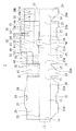
図1は、本発明の包装箱の一実施形態を平面状に展開して示す展開図である。図1に示すように本実施形態の包装箱1は、第1乃至第4壁部11〜14を各折り目線15を介して順次連接し、第1壁部11の側縁に折り目線16を介して継代片17を連接し、第1乃至第4壁部11〜14の下縁に折り目線18を介してそれぞれの底片21〜24を連接している。
FIG. 1 is a development view showing an embodiment of the packaging box of the present invention in a flat form. As shown in FIG. 1, the
また、第1壁部11の上縁に折り目線25を介して蓋部26を連接し、蓋部26の上縁に折り目線27を介して差し込み片28を連接し、折り目線27の中央に差し込み口29を形成している。
Further, the
更に、第2壁部12の上縁に折り目線31を介して第1緩衝用フラップ41を連接し、第1緩衝用フラップ41に2本の折り目線32を形成している。
Further, a
また、第3壁部13の上縁に折り目線33を介して第2乃至第4緩衝用フラップ42〜44を連接している。更に、第2緩衝用フラップ42に2本の折り目線34を形成している。また、第3及び第4緩衝用フラップ43、44を折り目線33に隣接する共有領域47で一体化し、共有領域47に折れ目線39を形成し、第3緩衝用フラップ43に2本の折り目線35を形成し、第4緩衝用フラップ44に2本の折れ目線36を形成している。更に、折り目線33の中央に差し込み片45及び差し込み口46を形成している。また、差し込み片45の先端及び両縁に切り込み57を形成し、第3壁部13の内側に及ぶ切り込み57の両側終端を結ぶように折れ目線58を形成している。
Further, second to fourth buffering flaps 42 to 44 are connected to the upper edge of the
更に、第2及び第3緩衝用フラップ42、43に隣接するスペースに第1補足緩衝片51を形成し、第1補足緩衝片51と第2及び第3緩衝用フラップ42、43との間に切り取り線48を形成している。また、第3及び第4緩衝用フラップ43、44が互いに離間したスペースに第2補足緩衝片52を形成し、第2補足緩衝片52と第3及び第4緩衝用フラップ43、44との間に切り取り線49を形成している。更に、第1補足緩衝片51に2本の折り目線53を形成し、第2補足緩衝片52に4本の折り目線54を形成している。
Further, a first
また、第4壁部14の上縁に折り目線37を介して押圧緩衝用フラップ55を連接し、押圧緩衝用フラップ55に2本の折り目線38a、38bを形成し、一方の折り目線38bの2箇所に小孔56を形成している。
Further, a
この平面状に展開された包装箱1は、1枚のダンボールを該展開された包装箱1の輪郭に沿って裁断し、各折り目線に沿ってダンボールを潰し、第1及び第2補足緩衝片51、52の切り取り線48、49を形成したものである。各切り取り線48、49は、例えばミシン目状に切り込みを入れて形成されたものであり、包装箱1の組み立てのときには、手によって第1及び第2補足緩衝片51、52を容易に切り離すことができるようにされている。
The
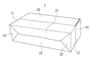
このような包装箱1は、図2に示すようなトナーカートリッジ2を収容して保護するために用いられる。このトナーカートリッジ2は、電子写真方式の画像形成装置で用いられるトナーを収納しており、画像形成装置に着脱自在に装着され、装着された状態で駆動されて、トナーを画像形成装置に供給する。このトナーカートリッジ2は、画像形成装置からの駆動力を受けるギアユニット61、トナーを画像形成装置へと供給する供給口に設けられた供給口シャッター(図示せず)、及び画像形成装置からの廃トナーを受け入れて回収する回収口に設けられた回収口シャッター63等を有している。
Such a
これらのギアユニット61、供給口シャッター(図示せず)、及び回収口シャッター63等は、トナーカートリッジ2の本体外側に設けられて露出しており、それらが衝撃等を受けて損傷すると、トナーカートリッジ2の機能が損なわれる。また、供給口シャッターが衝撃等を受けて開くと、トナーカートリッジ2の内部のトナーが漏れ出す。このため、包装箱1には、ギアユニット61、供給口シャッター、及び回収口シャッター63等を保護するための複数の緩衝部が設けられている。これらの緩衝部は、包装箱1を組み立てるときに包装箱1と一体的に形成されるものである。
The
次に、本実施形態の包装箱1を組み立てる手順を説明する。まず、第1及び第2補足緩衝片51、52を各切り取り線48、49で切り離しておく。そして、図3に示すように第1乃至第4壁部11〜14を各折り目線15で折り曲げ、継代片17を折り目線16で折り曲げて、継代片17を第4壁部14の内側面に固定し、第1乃至第4壁部11〜14を矩形の筒状にする。更に、各底片21〜24を折り目線18で折り曲げて、各底片21〜24の間の隙間に該各底片21〜24の差し込み片21a〜24aを差し込み、各底片21〜24を組み合わせて、包装箱1の底を形成する。
Next, the procedure for assembling the
引き続いて、図4に示すように第1緩衝用フラップ41を折り目線31で包装箱1の内側に折り込み、第1緩衝用フラップ41を2本の折り目線32で山折にして、図5に示すような第1緩衝部71を形成する。このとき、第1緩衝用フラップ41が2本の折り目線32で3つの区画部41a、41b、41cに区画され、区画部41aが包装箱1の底に重なり、区画部41bが第2壁部12と対向して、区画部41bと第2壁部12との間に空間が形成され、区画部41cが第2壁部12の上縁と同一高さとなる。
Subsequently, as shown in FIG. 4, the
また、図4に示すように押圧緩衝用フラップ55を、折り目線37で山折にし、折り目線38aで谷折にし、折り目線38bで山折にして、各折り目線37、38a、38bに折り目をつけておく。
Further, as shown in FIG. 4, the
一方、図6に示すように第1補足緩衝片51を2本の折り目線53で折り曲げて、第1補足緩衝片51を包装箱1の底に重ね合わせ、第1補足緩衝片51の各折り目線53を第2壁部12の方に向けて、第1補足緩衝片51を第4壁部14に隣接させる。また、図2に示すように第2補足緩衝片52を4本の折り目線54で折り曲げて、第2補足緩衝片52をトナーカートリッジ2の側部に形成されている溝に挟み込む。
On the other hand, as shown in FIG. 6, the first
この後、図5及び図7に示すようにトナーカートリッジ2を包装箱1に入れて、トナーカートリッジ2の一端を第1緩衝用フラップ41の区画部41bに当接させ、またトナーカートリッジ2の側部の溝に挟み込まれた第2補足緩衝片52を第3壁部13に当接させる。更に、押圧緩衝用フラップ55を折り目線37で包装箱1の内側に折り込んで、押圧緩衝用フラップ55の山折にされた折り目線38bの部位をトナーカートリッジ2の他端に形成されている凹所65(図2に示す)に嵌合させる。このとき、押圧緩衝用フラップ55が2本の折り目線38a、38bで3つの区画部55a、55b、55cに区画され、区画部55cが第4壁部14に重なり、各区画部55a、55bが第1壁部11と第3壁部13との間に挟み込まれ、これにより押圧緩衝部75が形成される。また、第1補足緩衝片51を第4壁部14とトナーカートリッジ2の他端との間に挟み込ませる。この状態で、トナーカートリッジ2は、包装箱1の底の上に置かれ、第1乃至第4壁部11〜14により囲まれて収納される。
Thereafter, as shown in FIGS. 5 and 7, the
次に、図7及び図8に示すように第2緩衝用フラップ42を折り目線33で包装箱1の内側に折り込み、第2緩衝用フラップ42を2本の折り目線34で山折にして、図9に示すような第2緩衝部72を形成し、第2緩衝部72をトナーカートリッジ2の側部に当接させる。このとき、第2緩衝用フラップ42が2本の折り目線34で3つの区画部42a、42b、42cに区画され、区画部42aの先端が第3壁部13の内側面に当接し、区画部42bが第3壁部13と対向して、区画部42bと第3壁部13との間に空間が形成され、区画部42cが第3壁部13の上縁と同一高さとなる。
Next, as shown in FIGS. 7 and 8, the
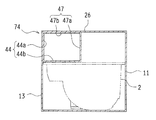
また、図10及び図11に示すように第3及び第4緩衝用フラップ43、44の共有領域47を折り目線33で包装箱1の内側に折り込み、共有領域47を折り目線39で山折にし、第3緩衝用フラップ43を2本の折り目線35で谷折にして、図12に示すような第3緩衝部73を形成し、更に第4緩衝用フラップ44を2本の折り目線36で山折にして、図13に示すような第4緩衝部74を形成する。このとき、図10及び図11に示すように共有領域47が折り目線39で2つの区画部47a、47bに区画され、区画部47aが第1壁部11と第3壁部13との間の空間を仕切り、区画部47bが第3壁部13の上縁と同一高さとなる。また、第3緩衝用フラップ43が一方の折り目線35で2つの区画部43a、43bに区画され、区画部43aが第1壁部11に当接し、区画部43bがトナーカートリッジ2の上面に当接する。更に、第4緩衝用フラップ44が一方の折り目線36で2つの区画部44a、44bに区画され、区画部44aが第3壁部13に当接し、区画部44bがトナーカートリッジ2の上面に当接する。従って、第3緩衝部73及び第4緩衝部74がトナーカートリッジ2の上面の互いに異なるそれぞれの箇所に当接する。
Further, as shown in FIGS. 10 and 11, the shared
引き続いて、図10及び図11に示すように差し込み片45を切り込み57で起こして、差し込み片45を折り目線58で谷折にし、差し込み片45を折り目線33で山折にする。
Subsequently, as shown in FIGS. 10 and 11, the
更に、図11及び図14に示すように蓋部26を折り目線25で山折にして、差し込み片28を折り目線27で山折にし、差し込み片28を第3壁部13側の差し込み口46に差し込み、第3壁部13側の差し込み片45を第1壁部11側の差し込み口29に差し込んで、蓋部26を閉じる。このとき、図12及び図13に示すように第3緩衝用フラップ43の区画部43bと蓋部26との間に空間が形成され、また第4緩衝用フラップ44の区画部44bと蓋部26との間にも空間が形成される。
Further, as shown in FIGS. 11 and 14, the
また、図5、図9、図12、及び図13に示すように閉じられた蓋部26により、第1緩衝用フラップ41の区画部41c、第2緩衝用フラップ42の区画部42c、及び第3及び第4緩衝用フラップ43、44の共有領域47の区画部47bが直接押えられて、第1緩衝用フラップ41、第2緩衝用フラップ42、第3緩衝用フラップ43、及び第4緩衝用フラップ44のそれぞれの折り込み形状が保持される。更に、押圧緩衝用フラップ55の折り目線38bの部位がトナーカートリッジ2の他端の凹所65に嵌合されて、押圧緩衝用フラップ55の折り込み形状が保持される。
Further, as shown in FIGS. 5, 9, 12, and 13, the
このような包装箱1においては、第2壁部12側の第1緩衝部71と第4壁部14側の押圧緩衝部75との間にトナーカートリッジ2が配置された状態で、押圧緩衝用フラップ55の山折にされた折り目線38bの部位がトナーカートリッジ2の他端の凹所65に嵌合されていることから、押圧緩衝用フラップ55が各折り目線37、38aで平面状に復元しようとする復元力によりトナーカートリッジ2が第2壁部12側の第1緩衝部71に押圧され、第1緩衝部71と押圧緩衝部75との間にトナーカートリッジ2が挟み込まれる。あるいは、弾性変形した押圧緩衝用フラップ55及び第1緩衝用フラップ41の復元力により第1緩衝部71と押圧緩衝部75との間にトナーカートリッジ2が挟み込まれる。また、第1補足緩衝片51が第4壁部14とトナーカートリッジ2の他端との間に挟み込まれている。このため、トナーカートリッジ2がその長手方向でガタツクことなく支持される。
In such a
更に、第3及び第4緩衝部73、74がトナーカートリッジ2の上面に当接している。このため、トナーカートリッジ2が上下方向でガタツクことなく支持される。また、包装箱1を上方から視たときに、第3緩衝用フラップ43の区画部43b(第3緩衝部73)がトナーカートリッジ2の横方向の片側半分を押え、第4緩衝用フラップ44の区画部44b(第4緩衝部74)がトナーカートリッジ2の横方向の他の片側半分を押えているので、トナーカートリッジ2が包装箱1の内側で転がることなく安定的に支持される。
Further, the third and
また、第2緩衝部72がトナーカートリッジ2の側部に当接し、かつトナーカートリッジ2の側部の溝に挟み込まれた第2補足緩衝片52が第3壁部13に当接しているので、トナーカートリッジ2が横方向でガタツクことなく支持される。
In addition, since the
従って、トナーカートリッジ2は、包装箱1の内側で長手方向、上下方向、及び横方向でガタツクことなく、また転がることなく安定的に支持される。
Therefore, the
また、閉じられた蓋部26により、第1緩衝用フラップ41、第2緩衝用フラップ42、第3緩衝用フラップ43、及び第4緩衝用フラップ44のそれぞれの折り込み形状が保持され、また押圧緩衝用フラップ55の折り目線38bの部位が凹所65に嵌合されて、押圧緩衝用フラップ55の折り込み形状が保持されているので、トナーカートリッジ2の安定的な支持が維持される。
In addition, the
一方、第2壁部12とトナーカートリッジ2との間には第1緩衝部71が介在するので、衝撃等が第2壁部12に加わったときには、第1緩衝部71が第2壁部12と共に変形して、衝撃等が第1緩衝部71及び第2壁部12で吸収されて弱められ、衝撃等がトナーカートリッジ2に直接作用することはなく、トナーカートリッジ2が保護される。
On the other hand, since the
更に、第1緩衝部71は、第1緩衝用フラップ41の区画部41bと第2壁部12との間に空間を形成していることから、第1緩衝部71及び第2壁部12がその空間で容易に変形して、衝撃等が第1緩衝部71及び第2壁部12で効果的に吸収されて弱められ、衝撃等がトナーカートリッジ2に直接作用することはなく、トナーカートリッジ2がより確実に保護される。
Further, since the
また、第4壁部14とトナーカートリッジ2との間には押圧緩衝部75が介在し、第4壁部14とトナーカートリッジ2との間には空間が形成されていることから、衝撃等が第4壁部14に加わったときには、押圧緩衝部75が第4壁部14と共にその空間で容易に変形して、衝撃等が押圧緩衝部75及び第4壁部14で効果的に吸収されて弱められ、トナーカートリッジ2が保護される。特に、第4壁部14に対向するトナーカートリッジ2の端部にはギアユニット61が設けられているので、押圧緩衝部75により第4壁部14とトナーカートリッジ2との間の空間が格別に広くされて、ギアユニット61が効果的に保護されるようにしている。従って、押圧緩衝部75は、トナーカートリッジ2を押圧して保持するだけではなく、緩衝部としての機能も果たす。
In addition, since a
更に、第3壁部13とトナーカートリッジ2の側部(回収口シャッター63)との間には第2緩衝部72が介在し、第2緩衝用フラップ42の区画部42bと第3壁部13との間には空間が形成されている。また、押圧緩衝用フラップ55の各区画部55a、55b(押圧緩衝部75)が第1壁部11と第3壁部13との間に挟み込まれている。このため、衝撃等が第1壁部11や第3壁部13に加わったときには、第2緩衝部72、押圧緩衝部75、第1壁部11、及び第3壁部13が変形して、衝撃等が弱められ、トナーカートリッジ2が保護される。
Further, a
また、蓋部26とトナーカートリッジ2の上面との間には第3及び第4緩衝部73、74が介在し、第3緩衝用フラップ43の区画部43bと蓋部26との間に空間が形成され、第4緩衝用フラップ44の区画部44bと蓋部26との間にも空間が形成されているので、衝撃等が蓋部26に加わったときには、第3緩衝部73、第4緩衝部74、及び蓋部26がそれらの空間で容易に変形して、衝撃等が弱められ、トナーカートリッジ2が保護される。
In addition, third and
従って、衝撃等が第2壁部12や第4壁部14に加わったときには、衝撃等が第1緩衝部71、押圧緩衝部75、第2壁部12、及び第4壁部14で吸収されて弱められ、また衝撃等が第1壁部11や第3壁部13に加わったときには、衝撃等が第2緩衝部72、押圧緩衝部75、第1壁部11、及び第3壁部13で吸収されて弱められ、更に衝撃等が蓋部26に加わったときには、衝撃等が第3緩衝部73、第4緩衝部74、及び蓋部26で吸収されて弱められる。これにより、トナーカートリッジ2が良好に保護される。
Therefore, when an impact or the like is applied to the
また、閉じられた蓋部26により、第1緩衝用フラップ41、第2緩衝用フラップ42、第3緩衝用フラップ43、第4緩衝用フラップ44のそれぞれの折り込み形状が保持され、また押圧緩衝用フラップ55の折り目線38bの部位が凹所65に嵌合されて、押圧緩衝用フラップ55の折り込み形状が保持され、それらが変形することはないので、第1緩衝部71、第2緩衝部72、第3緩衝部、第4緩衝部74、及び押圧緩衝部75による衝撃等の吸収機能を維持することができる。
Further, the
しかも、第1乃至第4緩衝部71〜74及び押圧緩衝部75は、第1乃至第4壁部11〜14に連接された第1乃至第4緩衝用フラップ41〜44及び押圧緩衝用フラップ55を包装箱1の内側に折り込むことにより形成されたものである。また、第1及び第2補足緩衝片51、52は、平面状に展開された包装箱1の空きスペースを利用して形成されたものである。このため、パルプモールドや発泡スチロールなどの成形品を緩衝部材として用いたり、ダンボールを別途組み立てたものを緩衝部材として用いたりする必要がなく、コストを抑えることができ、資源の節減や廃棄物の低減を実現することができ、リサイクルも容易となり、延いては自然環境の保全にも役立つ。
In addition, the first to
このように本実施形態の包装箱1では、第1乃至第4壁部11〜14に連接された第1乃至第4緩衝用フラップ41〜44及び押圧緩衝用フラップ55を包装箱1の内側に折り込んで、第1乃至第4緩衝部71〜74及び押圧緩衝部75を形成し、第1乃至第4緩衝部71〜74及び押圧緩衝部75によりトナーカートリッジ2を効果的に支持及び保護することができ、格別な緩衝部材を用いる必要がなく、資源の節減や廃棄物の低減を実現することができる。
Thus, in the
尚、上記実施形態では、第1乃至第4壁部11〜14に連接された第1乃至第4緩衝用フラップ41〜44及び押圧緩衝用フラップ55を例示しているが、第1乃至第4緩衝用フラップ41〜44及び押圧緩衝用フラップ55を適宜選択的に組み合わせて用いたり、第1乃至第4緩衝用フラップ41〜44及び押圧緩衝用フラップ55を単独で用いたりしても構わない。また、トナーカートリッジ2だけではなく、他の種類の被収容物を収容するために、本発明の包装箱を適用しても構わない。
In the above embodiment, the first to fourth buffer flaps 41 to 44 and the
以上、添付図面を参照しながら本発明の好適な実施形態及び変形例について説明したが、本発明は係る例に限定されないことは言うまでもない。当業者であれば、特許請求の範囲に記載された範疇内において、各種の変更例または修正例に想到し得ることは明らかであり、それらについても当然に本発明の技術的範囲に属するものと解される。 As mentioned above, although preferred embodiment and modification of this invention were described referring an accompanying drawing, it cannot be overemphasized that this invention is not limited to the example which concerns. It will be apparent to those skilled in the art that various changes and modifications can be made within the scope of the claims, and these are naturally within the technical scope of the present invention. It is understood.
1 包装箱
2 トナーカートリッジ
11〜14 第1乃至第4壁部
15、16、18、25、27、31〜37、38a、38b、39、53、54 折り目線
17 継代片
21〜24 底片
26 蓋部
28、45 差し込み片
29、46 差し込み口
41〜44 第1乃至第4緩衝用フラップ
47 共有領域
48、49 切り取り線
51、52 第1及び第2補足緩衝片
55 押圧緩衝用フラップ
56 小孔
61 ギアユニット
63 回収口シャッター
65 凹所
71〜74 第1乃至第4緩衝部
75 押圧緩衝部
DESCRIPTION OF
Claims (9)
前記各壁部のいずれかに連接された緩衝用フラップと、
前記緩衝用フラップが連接された前記壁部に対向する他の壁部に連接された押圧用フラップとを備え、
前記緩衝用フラップを前記包装箱の内側に折り込むことにより前記被収容物を保護する緩衝部を形成し、
前記押圧用フラップを前記包装箱の内側に折り込むことにより形成されて、前記被収容物を前記緩衝部の側に押圧する押圧部を設け、
前記押圧部および前記緩衝部は、連接した壁部から離間して、前記被収容物の端部に当接し、
前記押圧用フラップの山折りにされた折り目線を前記被収容物の一方の端部に接触させ、前記緩衝用フラップの折り目線で区画された平面である区画部を前記被収容物の他方の端部に接触させること
を特徴とする包装箱。 A packaging box having a plurality of walls surrounding the item to be contained,
A buffering flap connected to any one of the walls;
A pressing flap connected to another wall portion facing the wall portion to which the buffering flap is connected;
Forming a buffer part that protects the object to be stored by folding the buffering flap inside the packaging box,
It is formed by folding the pressing flap inside the packaging box, and a pressing portion that presses the object to be stored toward the buffer portion is provided.
The pressing portion and the buffer portion are spaced apart from the connected wall portions and abut against the end portion of the object to be stored,
The other pre-Symbol mountain folding has been crease line of the pressing flap is brought into contact with one end of the contained object, the buffer for the contained object partition portion is compartmentalized plane flap fold lines A packaging box characterized by being brought into contact with the end of the packaging.
前記緩衝部は、前記包装箱の内側に折り込まれた前記緩衝用フラップと該緩衝用フラップが連接された前記壁部との間に空間を形成することを特徴とする包装箱。 The packaging box according to claim 1,
The packaging box is characterized in that a space is formed between the cushioning flap folded inside the packaging box and the wall part connected to the cushioning flap.
切り取り線で区切って前記壁部に連接された補足緩衝片を備え、
前記補足緩衝片は、前記壁部から切り離されて内部に収容され、前記被収容物を押圧すること
を特徴とする包装箱。 The packaging box according to claim 1,
Comprising a supplemental buffer piece connected to the wall section by a cut line;
The packaging box, wherein the supplemental buffer piece is separated from the wall portion and accommodated therein, and presses the object.
前記押圧部は、前記被収容物を保持することを特徴とする包装箱。 The packaging box according to claim 1,
The said press part hold | maintains the said to-be-contained object, The packaging box characterized by the above-mentioned.
前記各壁部のいずれかに連接された蓋部を備え、
前記蓋部が閉じられた状態では、前記蓋部により前記緩衝部が押えられることを特徴とする包装箱。 A packaging box according to any one of claims 1 to 4,
A lid connected to any one of the walls;
The packaging box, wherein the buffer portion is pressed by the lid portion when the lid portion is closed.
前記各壁部のいずれかに連接された蓋部を備え、
前記蓋部が連接された前記壁部に対向する別の壁部に前記緩衝用フラップを連接して、前記緩衝用フラップを前記包装箱の内側に折り込むことにより前記被収容物を保護する緩衝部を形成し、前記蓋部が閉じられた状態では、前記蓋部により前記緩衝部が押えられることを特徴とする包装箱。 The packaging box according to claim 1,
A lid connected to any one of the walls;
The buffer part which protects the said to-be-contained object by connecting the said buffer flap to the other wall part facing the said wall part with which the said cover part was connected, and folding the said buffer flap inside the said packaging box The packaging box is characterized in that, when the lid portion is closed, the buffer portion is pressed by the lid portion.
前記緩衝部は、前記包装箱の内側に折り込まれた前記緩衝用フラップと閉じられた前記蓋部との間に空間を形成することを特徴とする包装箱。 The packaging box according to claim 6,
The packaging box is characterized in that a space is formed between the cushioning flap folded inside the packaging box and the closed lid.
前記緩衝用フラップを前記各壁部のいずれかに複数並べて連接し、
前記各緩衝用フラップを前記包装箱の内側に折り込むことにより前記被収容物を保護する複数の緩衝部を形成したことを特徴とする包装箱。 A packaging box according to any one of claims 1 to 7,
A plurality of the buffering flaps are arranged and connected to any one of the wall portions,
A packaging box, wherein a plurality of buffer parts for protecting the object to be stored are formed by folding each of the cushioning flaps inside the packaging box.
前記被収容物は、外部に露呈したギア又はシャッターを有するトナーカートリッジであり、
前記緩衝部を前記ギア又はシャッターの部位に設けたことを特徴とする包装箱。 A packaging box according to any one of claims 1 to 8 ,
The container is a toner cartridge having a gear or a shutter exposed to the outside,
A packaging box, wherein the buffer portion is provided at a portion of the gear or the shutter.
Priority Applications (1)
| Application Number | Priority Date | Filing Date | Title |
|---|---|---|---|
| JP2013114304A JP6473286B2 (en) | 2013-05-30 | 2013-05-30 | Packaging box |
Applications Claiming Priority (1)
| Application Number | Priority Date | Filing Date | Title |
|---|---|---|---|
| JP2013114304A JP6473286B2 (en) | 2013-05-30 | 2013-05-30 | Packaging box |
Publications (2)
| Publication Number | Publication Date |
|---|---|
| JP2014231388A JP2014231388A (en) | 2014-12-11 |
| JP6473286B2 true JP6473286B2 (en) | 2019-02-20 |
Family
ID=52125042
Family Applications (1)
| Application Number | Title | Priority Date | Filing Date |
|---|---|---|---|
| JP2013114304A Active JP6473286B2 (en) | 2013-05-30 | 2013-05-30 | Packaging box |
Country Status (1)
| Country | Link |
|---|---|
| JP (1) | JP6473286B2 (en) |
Family Cites Families (7)
| Publication number | Priority date | Publication date | Assignee | Title |
|---|---|---|---|---|
| JPH0212386Y2 (en) * | 1985-04-10 | 1990-04-06 | ||
| JPH0290273U (en) * | 1988-12-28 | 1990-07-17 | ||
| JPH111224A (en) * | 1997-06-13 | 1999-01-06 | Sony Corp | Packaging container |
| JP3095085U (en) * | 2003-01-06 | 2003-07-18 | 菊水酒造株式会社 | Packaging box |
| JP2006044721A (en) * | 2004-08-03 | 2006-02-16 | Hiromoto:Kk | Flower transporting box |
| JP5085154B2 (en) * | 2007-02-21 | 2012-11-28 | 京セラドキュメントソリューションズ株式会社 | Packing material for plate and packing body using the same |
| JP5417769B2 (en) * | 2008-08-25 | 2014-02-19 | コニカミノルタ株式会社 | Packing cushioning material |
-
2013
- 2013-05-30 JP JP2013114304A patent/JP6473286B2/en active Active
Also Published As
| Publication number | Publication date |
|---|---|
| JP2014231388A (en) | 2014-12-11 |
Similar Documents
| Publication | Publication Date | Title |
|---|---|---|
| JP6174397B2 (en) | Packaging box with buffer partition | |
| JP6473286B2 (en) | Packaging box | |
| JP2012012026A (en) | Packaging box with cushioning partition | |
| WO2023145561A1 (en) | Packing member | |
| JP5847369B2 (en) | Packing material | |
| KR200456896Y1 (en) | Paper box | |
| JP2006076585A (en) | Packaging box | |
| JP2009102030A (en) | Individually packaging box | |
| JP4959743B2 (en) | Packaging box | |
| JP2008001387A (en) | Storage container and shock absorbing material | |
| JP4271510B2 (en) | Packaging box | |
| JP6595367B2 (en) | Packaging box | |
| JP4636065B2 (en) | Packing box | |
| JP3112352U (en) | Packaging box | |
| JP7389720B2 (en) | packaging box | |
| JP3222010U (en) | Container package | |
| JP7235606B2 (en) | packaging box | |
| JP5137198B2 (en) | Flat rectangular battery packaging container | |
| CN217147017U (en) | Package and package assembly | |
| JP7498351B1 (en) | Packaging box | |
| JP3240518U (en) | container | |
| CN218807583U (en) | Packing carton inside lining and packing carton | |
| JP4481766B2 (en) | Packing structure | |
| JP4827663B2 (en) | Container | |
| JP2008222297A (en) | Packing material |
Legal Events
| Date | Code | Title | Description |
|---|---|---|---|
| A621 | Written request for application examination |
Free format text: JAPANESE INTERMEDIATE CODE: A621 Effective date: 20160225 |
|
| A977 | Report on retrieval |
Free format text: JAPANESE INTERMEDIATE CODE: A971007 Effective date: 20161216 |
|
| A131 | Notification of reasons for refusal |
Free format text: JAPANESE INTERMEDIATE CODE: A131 Effective date: 20170110 |
|
| A521 | Written amendment |
Free format text: JAPANESE INTERMEDIATE CODE: A523 Effective date: 20170303 |
|
| A02 | Decision of refusal |
Free format text: JAPANESE INTERMEDIATE CODE: A02 Effective date: 20170425 |
|
| A521 | Written amendment |
Free format text: JAPANESE INTERMEDIATE CODE: A523 Effective date: 20170623 |
|
| A911 | Transfer of reconsideration by examiner before appeal (zenchi) |
Free format text: JAPANESE INTERMEDIATE CODE: A911 Effective date: 20170703 |
|
| A912 | Removal of reconsideration by examiner before appeal (zenchi) |
Free format text: JAPANESE INTERMEDIATE CODE: A912 Effective date: 20170721 |
|
| A521 | Written amendment |
Free format text: JAPANESE INTERMEDIATE CODE: A523 Effective date: 20180613 |
|
| A521 | Written amendment |
Free format text: JAPANESE INTERMEDIATE CODE: A523 Effective date: 20181026 |
|
| A61 | First payment of annual fees (during grant procedure) |
Free format text: JAPANESE INTERMEDIATE CODE: A61 Effective date: 20190125 |
|
| R150 | Certificate of patent or registration of utility model |
Ref document number: 6473286 Country of ref document: JP Free format text: JAPANESE INTERMEDIATE CODE: R150 |