JP6472991B2 - Heat storage body disposed in exhaust pipe of internal combustion engine and exhaust gas purification system - Google Patents
Heat storage body disposed in exhaust pipe of internal combustion engine and exhaust gas purification system Download PDFInfo
- Publication number
- JP6472991B2 JP6472991B2 JP2014250617A JP2014250617A JP6472991B2 JP 6472991 B2 JP6472991 B2 JP 6472991B2 JP 2014250617 A JP2014250617 A JP 2014250617A JP 2014250617 A JP2014250617 A JP 2014250617A JP 6472991 B2 JP6472991 B2 JP 6472991B2
- Authority
- JP
- Japan
- Prior art keywords
- heat storage
- storage body
- exhaust gas
- temperature
- heating member
- Prior art date
- Legal status (The legal status is an assumption and is not a legal conclusion. Google has not performed a legal analysis and makes no representation as to the accuracy of the status listed.)
- Expired - Fee Related
Links
Images


Classifications
-
- Y—GENERAL TAGGING OF NEW TECHNOLOGICAL DEVELOPMENTS; GENERAL TAGGING OF CROSS-SECTIONAL TECHNOLOGIES SPANNING OVER SEVERAL SECTIONS OF THE IPC; TECHNICAL SUBJECTS COVERED BY FORMER USPC CROSS-REFERENCE ART COLLECTIONS [XRACs] AND DIGESTS
- Y02—TECHNOLOGIES OR APPLICATIONS FOR MITIGATION OR ADAPTATION AGAINST CLIMATE CHANGE
- Y02T—CLIMATE CHANGE MITIGATION TECHNOLOGIES RELATED TO TRANSPORTATION
- Y02T10/00—Road transport of goods or passengers
- Y02T10/10—Internal combustion engine [ICE] based vehicles
- Y02T10/12—Improving ICE efficiencies
Description
本発明は内燃機関の排気管に配置される蓄熱体および内燃機関における排気ガスの浄化システムに関する。 The present invention relates to a heat storage body disposed in an exhaust pipe of an internal combustion engine and an exhaust gas purification system in the internal combustion engine.
近年における内燃機関の排出ガス(排気ガス)成分に関する規制に対応するために、内燃機関の排気管経路には種々の排気ガス浄化装置が配置されている。これら排気ガス浄化装置は、触媒や尿素水といった化学物質とNOxやPM(粒子状物質:Particulate Matter)といった排気ガス成分との間における化学反応によって排気ガス成分を浄化しており、化学物質が最適な浄化性能を発揮する温度域が存在する。一方で、内燃機関における燃焼効率の向上に伴い排気ガス温度は低下傾向にある。そこで、排気管経路に蓄熱体を配置して、排気管経路の温度維持を図る技術(たとえば、特許文献1)や、排気管経路を加熱装置によって加熱する技術(たとえば、特許文献2)が提案されている。 In order to comply with the regulations regarding the exhaust gas (exhaust gas) component of the internal combustion engine in recent years, various exhaust gas purification devices are arranged in the exhaust pipe path of the internal combustion engine. These exhaust gas purifiers purify exhaust gas components by chemical reaction between chemical substances such as catalyst and urea water and exhaust gas components such as NOx and PM (Particulate Matter). There is a temperature range that exhibits a good purification performance. On the other hand, the exhaust gas temperature tends to decrease as the combustion efficiency in the internal combustion engine improves. Therefore, a technique for arranging a heat storage body in the exhaust pipe path to maintain the temperature of the exhaust pipe path (for example, Patent Document 1) and a technique for heating the exhaust pipe path by a heating device (for example, Patent Document 2) are proposed. Has been.
しかしながら、蓄熱体を用いる技術では、蓄熱体自体の温度が低い場合、蓄熱体と接触させることで却って排気ガス温度を低下させてしまい排気ガスを浄化できないという問題がある。また、加熱装置を用いる技術では、内燃機関から排気される排気ガス温度が浄化装置の最適温度域よりも高い場合に、浄化装置が劣化する、排気ガスが有する熱エネルギを有効活用できない、加熱装置による浄化装置の加熱を効率的に実行できないという問題があった。 However, in the technique using the heat storage body, when the temperature of the heat storage body itself is low, there is a problem that the exhaust gas temperature cannot be reduced by contacting the heat storage body and the exhaust gas cannot be purified. Further, in the technology using the heating device, when the exhaust gas temperature exhausted from the internal combustion engine is higher than the optimum temperature range of the purification device, the purification device deteriorates, and the heat energy of the exhaust gas cannot be effectively used. There has been a problem that heating of the purification device by cannot be performed efficiently.
したがって、内燃機関から排出される排気ガスの温度に依存せず、効率良く浄化装置の性能を発揮させる技術が望まれている。 Therefore, there is a demand for a technique that can efficiently exhibit the performance of the purification device without depending on the temperature of the exhaust gas discharged from the internal combustion engine.
本発明は、上述の課題を解決するためになされたものであり、以下の態様として実現することが可能である。 The present invention has been made to solve the above-described problems, and can be realized as the following aspects.
第1の態様は、内燃機関の排気管に配置される蓄熱体を提供する。第1の態様に係る蓄熱体は、ハウジングと、前記ハウジング内に配置されている蓄熱部材と、前記蓄熱部材と離間されて対向配置されている加熱部材と、前記ハウジング内に形成されている、前記内燃機関から排気される排気ガスが流れるガス流路部とを備える。 A 1st aspect provides the thermal storage body arrange | positioned at the exhaust pipe of an internal combustion engine. The heat storage body according to the first aspect is formed in a housing, a heat storage member disposed in the housing, a heating member spaced apart from the heat storage member, and the housing, A gas flow path portion through which exhaust gas exhausted from the internal combustion engine flows.
第1の態様に係る蓄熱体によれば、内燃機関から排出される排気ガスの温度に依存せず、効率良く浄化装置の性能を発揮させることができる。 According to the heat storage body according to the first aspect, the performance of the purification device can be exhibited efficiently without depending on the temperature of the exhaust gas discharged from the internal combustion engine.
第1の態様に係る蓄熱体において、さらに、前記蓄熱部材と前記加熱部材とを離間させるための支持手段を備えても良く、前記支持手段は、前記蓄熱部材および前記加熱部材の少なくともいずれか一方に形成されている突状部であっても良い。この場合には、蓄熱部材と加熱部材との間の熱交換を抑制または防止することができる。 The heat storage body according to the first aspect may further include support means for separating the heat storage member and the heating member, and the support means is at least one of the heat storage member and the heating member. It may be a protruding portion formed on the surface. In this case, heat exchange between the heat storage member and the heating member can be suppressed or prevented.
第1の態様に係る蓄熱体において、前記加熱部材は前記蓄熱部材に内包されていても良く、前記加熱部材は前記蓄熱部材の少なくとも一部に内包されていても良い。この場合には、蓄熱部材によって加熱部材から放出される熱エネルギの拡散を抑制または防止することができる。 In the heat storage body according to the first aspect, the heating member may be included in the heat storage member, and the heating member may be included in at least a part of the heat storage member. In this case, diffusion of thermal energy released from the heating member by the heat storage member can be suppressed or prevented.
第1の態様に係る蓄熱体において、前記加熱部材は前記蓄熱部材を内包していても良く、前記加熱部材は前記蓄熱部材の少なくとも一部を覆っていても良い。この場合には、加熱部材によって蓄熱部材をも加熱することができる。 In the heat storage body according to the first aspect, the heating member may include the heat storage member, and the heating member may cover at least a part of the heat storage member. In this case, the heat storage member can also be heated by the heating member.
第1の態様に係る蓄熱体において、前記蓄熱部材の少なくとも一部には潜熱蓄熱体が含まれていても良い。この場合には、蓄熱部材による所定の温度での加熱を長時間にわたり持続することができる。 In the heat storage body according to the first aspect, at least a part of the heat storage member may include a latent heat storage body. In this case, heating at a predetermined temperature by the heat storage member can be continued for a long time.
第1の態様に係る蓄熱体において、前記ガス流路部は、前記加熱部材と前記蓄熱材とが離間して配置されていることにより前記加熱部材と前記蓄熱材との間に形成されている離間空間であっても良い。この場合には、加熱部材および蓄熱部材の少なくとも一方によって排気ガスの温度を昇温させることができると共に、排気ガス流路部を別途備えることなく外気ガスを流動させることができる。 The heat storage body which concerns on a 1st aspect WHEREIN: The said gas flow path part is formed between the said heating member and the said thermal storage material by the said heating member and the said thermal storage material being spaced apart and arrange | positioning. It may be a separated space. In this case, the temperature of the exhaust gas can be raised by at least one of the heating member and the heat storage member, and the outside air gas can be flowed without separately providing an exhaust gas flow path portion.
第1の態様に係る蓄熱体において、前記蓄熱部材の融点は、前記ハウジングの融点よりも低くても良い。この場合には、蓄熱部材の蓄熱に際し、ハウジングの損傷を抑制または防止することができる。 In the heat storage body according to the first aspect, the melting point of the heat storage member may be lower than the melting point of the housing. In this case, damage to the housing can be suppressed or prevented during heat storage of the heat storage member.
第1の態様に係る蓄熱体において、前記加熱部材は前記ハウジング内における前記排気ガスの流れる方向に延伸していても良い。この場合には、排気ガスと加熱部材との接触面積を大きくすることができる。 In the heat storage body according to the first aspect, the heating member may extend in a direction in which the exhaust gas flows in the housing. In this case, the contact area between the exhaust gas and the heating member can be increased.
第1の態様に係る蓄熱体において、前記加熱部材は棒状であり、前記ガス流路部は、前記加熱部材と、前記加熱部材の外周に配置されている前記ハウジングまたは前記蓄熱材とによって規定されている流路空間であっても良い。この場合には、排気ガスと加熱部材との接触面積を大きくすることができる。 In the heat storage body according to the first aspect, the heating member has a rod shape, and the gas flow path portion is defined by the heating member and the housing or the heat storage material disposed on an outer periphery of the heating member. It may be a channel space. In this case, the contact area between the exhaust gas and the heating member can be increased.
第1の態様に係る蓄熱体において、前記加熱部材は複数備えられていても良く、前記ガス流路部は、複数の前記加熱部材のそれぞれの周囲に配置されていても良い。この場合には、排気ガスと加熱部材との接触面積を増大させることが可能となり、排気ガスの昇温効率を向上させることができる。 The heat storage body which concerns on a 1st aspect WHEREIN: The said heating member may be provided with two or more, and the said gas flow path part may be arrange | positioned around each of the said several heating member. In this case, the contact area between the exhaust gas and the heating member can be increased, and the temperature raising efficiency of the exhaust gas can be improved.
第2の態様は、内燃機関の排気経路に配置される排気ガスの浄化システムを提供する。第2の態様に係る浄化システムは、前記排気ガスを浄化するための浄化装置と、前記浄化装置の前段に配置されている上記第1の態様に係るいずれかの蓄熱体とを備える。 A 2nd aspect provides the purification system of the exhaust gas arrange | positioned at the exhaust path of an internal combustion engine. The purification system which concerns on a 2nd aspect is provided with the purification apparatus for purifying the said exhaust gas, and the any one thermal storage body which concerns on the said 1st aspect arrange | positioned in the front | former stage of the said purification apparatus.
第2の態様に係る浄化システムによれば、内燃機関から排出される排気ガスの温度に依存せず、効率良く浄化装置の性能を発揮させることができる。 According to the purification system of the second aspect, the performance of the purification device can be exhibited efficiently without depending on the temperature of the exhaust gas discharged from the internal combustion engine.
本発明に係る排気ガスの浄化システムおよび排気ガスシステムに用いたれる発熱体の一態様として、ディーゼルエンジン(内燃機関)を備える車両を例にとって以下説明する。図1は本実施形態において用いられる排気ガスの浄化システムを備える車両を概略的に示す説明図である。 As an embodiment of the exhaust gas purification system and the heating element used in the exhaust gas system according to the present invention, a vehicle including a diesel engine (internal combustion engine) will be described below as an example. FIG. 1 is an explanatory diagram schematically showing a vehicle equipped with an exhaust gas purification system used in the present embodiment.
車両500は、ディーゼルエンジン(以下、「エンジン」と呼ぶ。)510、4つの車輪520および排気ガスの浄化システム10を備えている。エンジン510は、軽油を燃料とし、燃料の爆発燃焼によって駆動力を出力し、また、爆発燃焼に伴いNOx(窒素酸化物)およびPM(粒子状物質)を含む排気ガスを排気系統に備えられた浄化システム10を介して大気に排出する。
The
浄化システム10は、排気管11上に種々の排気ガス浄化装置を備えている。排気管11は、エンジン510側(排気ガス流れの上流側)においてマニフォールド11aを介してエンジン510と接続され、排気ガス流れの最下流側にはマフラエンドパイプ11bを備えている。浄化システム10は、排気ガス流れの上流側から、ディーゼル酸化触媒(DOC)12、ディーゼル微粒子フィルタ(DPF)13、蓄熱体20、選択触媒還元装置(SCR)14およびアンモニアスリップ・ディーゼル酸化触媒(NH3DOC)15を排気管11上に備えている。排気管11上におけるDOC12の前段には燃料噴射装置17が配置されても良く、SCR装置14の前段には尿素水噴射装置18が配置されている。なお、本実施例における排気管上という用語は、排気管の内側、および排気管の途中(排気管の一部を構成)のいずれをも意味する。
The
ディーゼル酸化触媒12は、白金(Pt)、パラジウム(Pd)等の貴金属を触媒として担持し、排気ガス中に含まれる未燃焼ガス成分である一酸化炭素(CO)および炭化水素(HC)を酸化して、二酸化炭素(CO2)および水(H2O)へと変換すると共に、排気ガス中に含まれる一酸化窒素(NO)を酸化して、二酸化窒素(NO2)に変換する。
The
ディーゼル微粒子フィルタ13は、排気ガス中に含まれる粒子状物質(PM)を多孔質セラミックの微細な間隙で捕集するフィルタである。多孔質の表面には白金等の金属触媒が塗布されており、ディーゼル微粒子フィルタ13は、ディーゼル酸化触媒12により生成されるNO2の存在下において、粒子状物質が、250〜300℃の雰囲気中で触媒と化学反応を起こし、二酸化炭素(CO2)および水(H2O)に変換されることによって自然再生される。ディーゼル微粒子フィルタ13は、ディーゼル酸化触媒12に対して燃料噴射装置17を介して直接または排気行程を経てエンジン510から間接的に燃料を供給し、燃料由来の炭化水素を触媒燃焼させて排気温度を450℃以上として捕集された粒子状物質を酸化させる強制再生によっても再生され得る。
The
選択触媒還元(SCR)装置14は、ゼオライト系触媒またはバナジウム系触媒を担持し、NOxを選択的に還元する装置である。選択触媒還元装置14においては、一般的に、選択触媒還元装置14入口前段において尿素水噴射装置18により尿素水を排気ガスに吹きかけ、尿素水の熱分解、加水分解反応を経て、アンモニア(NH3)を生成し、排気ガス中のNOx成分を窒素(N2)および水(H2O)に変換する。したがって、選択触媒還元装置14の入口前段においては、排気ガス温度は、尿素水からアンモニアを得るために、適切な温度、例えば、200℃以上の温度であることが求められている。
The selective catalytic reduction (SCR)
アンモニアスリップ・ディーゼル酸化触媒15は、ディーゼル酸化触媒12と同様の触媒を担持し、選択触媒還元装置14において反応に供しなかったアンモニアを酸化分解して、窒素またはNOxを生成する。
The ammonia slip /
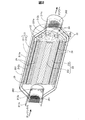
本実施形態に係る蓄熱体20について以下に詳述する。図2は本実施形態において用いられる蓄熱体の内部構成を示す斜視断面図である。図3は図1に示す本実施例において用いられる蓄熱体を3−3線で切断した断面図である。
The
蓄熱体20は、外側ケース211および内側ケース212を含むケース21(ハウジング)、加熱部材としてのヒータ22、潜熱蓄熱材231および顕熱蓄熱材232を含む蓄熱部材23、ヒータ22と蓄熱部材23との間に区画形成されている空間としての排気ガス流路(流路部)24、断熱材25、上流側蓋261、下流側蓋262および整流部材263を備えている。
The
外側ケース211および内側ケース212は、ステンレス鋼、酸化防止処理が施された鋼板から形成され、それぞれ、直線筒状の本体部211a、212aと、排気ガスの導入側と排出側において本体部211a、212aよりも小さな径を有する導入部211b、212bと排出部211c、212cとを有している。外側ケース211および内側ケース212は、本体部211a、212aと導入部211b、212bおよび排出部211c、212cとが断面視にて傾斜を有する略円錐台状の接続部によって連結されており、導入部211b、212bから本体部211a、212a、本体部211a,212aから排出部211c、121cへの排気ガスの流動を円滑にしている。
The outer case 211 and the
内側ケース212の導入部212bおよび排出部212cは、上流側蓋261および下流側蓋262の結合されており、上流側蓋261および下流側蓋262が外側ケース211の導入部211bおよび排出部211cに係合されることによって、内側ケース212は外側ケース211内に保持される。なお、内側ケース212の内壁面には断熱材25が配置されており、蓄熱部材23からの熱伝導が抑制されているが、大気中への放熱をさらに抑制するために、外側ケース211と内側ケース212との間には、断熱空間としての空間が区間形成されている。
The
上流側蓋261および下流側蓋262は、排気ガスが流動するための複数の流路(正面視では孔)を有する、多孔質金属製または多孔質セラミック製の円柱形部材である。上流側蓋261および下流側蓋262は、排気ガスの流れ方向における断熱を図るために配置されており、蓄熱体20内に熱を維持する。内側ケース212の導入部212bには、開口部が上流側蓋261に接する円筒形状の整流部材263が配置されている。整流部材263は底面側の周面に複数の孔を備え、導入部212bから導入された排気ガスが内側ケース212の径方向にわたって拡散するように排気ガスの流れを整流する。この結果、ヒータ22および蓄熱部材23との間の複数の排気ガス流路24には均一に排気ガスが行き渡る。蓄熱部材23は、排気ガス温度が蓄熱部材23の温度よりも高い場合には、排気ガスの熱エネルギーを吸収して蓄熱部材23の温度を上昇させ、維持(蓄熱)し、排気ガス温度が蓄熱部材23の温度よりも低い場合には、蓄熱している熱エネルギーを放出し、排気ガスを加温する。すなわち、排気ガスと蓄熱部材23との間では、両者の温度差に基づく熱交換が行われる。
The
図4は本実施形態に係る蓄熱体内部における蓄熱部材によるヒータの支持態様の一例を示す説明図である。ヒータ22はケース21内における排気ガスの流動方向に延伸する棒状の外形形状を有し、例えば、本実施形態においては、8本のヒータ22が用いられている。ヒータ22が複数個備えられることにより、ヒータ22と排気ガスとの接触面積を増大させ、ヒータ22による排気ガスの昇温効率を向上させることができる。本実施形態において用いられるヒータは、たとえば、ステンレス製のハウジング内部に配置されている発熱体と接続されている電極から延びる2本のリード線が一の端部から延出するカートリッジヒータである。図2においては説明を容易にするために2本のリード線は図示していないが、各ヒータ22のリード線は、ケース21の側面の任意の位置に形成されるリード線取り出し孔からケース21の外部に導かれ、外部のヒータコントローラ(図示しない)と接続され、通電による加熱温度が制御される。本実施形態においては、ヒータ22は、排気ガス温度が所定温度よりも低く、蓄熱部材23の温度が所定の温度よりも低い場合に、排気ガス温度を所定温度まで上昇させるために、あるいは、蓄熱部材23の温度を所定温度まで上昇させるために用いられる。ここで、蓄熱部材23の温度が所定の温度よりも低いか否かの判断は、蓄熱体20内部に設けられた温度センサ、または蓄熱体20の下流側外部に設けられた排気ガス温度センサといった、温度センサによって判断されても良く、あるいは、エンジン510の始動直後、または、エンジン510の始動後からの経過時間によって、一律に判断されても良い。
FIG. 4 is an explanatory diagram showing an example of a support mode of the heater by the heat storage member inside the heat storage body according to the present embodiment. The
蓄熱部材23のうち、潜熱蓄熱材231は、常温では固相であり、排気ガスの熱によって液相に相転移する蓄熱材であり、例えば、アルミニウム潜熱蓄熱材、LiNO2、NaNO2等の硝酸塩系溶融塩、LiCl、NaCl等の塩化物系溶融塩、LiCO2、K2CO2等のアルカリ金属炭酸塩系溶融塩を用いることができる。なお、本実施形態における潜熱蓄熱材231の望ましい融点は200℃〜600℃であり、ケース21の融点よりも低い。顕熱蓄熱材232は、例えば、ステンレス鋼、軟鋼、セラミックス材、金属粉末の焼結体、メタルハニカム等を用いることができる。
Of the
顕熱蓄熱材232は、各ヒータ22をそれぞれ独立して収容するヒータ収容空間232a、潜熱蓄熱材231を収容するための横断面視で略放射状の潜熱蓄熱材収容空間を備えている。なお、潜熱蓄熱材231は、固相状態時の体積よりも液相状態時の体積が大きいことから、潜熱蓄熱材収容空間は、液相状態における潜熱蓄熱材231の体積に合わせた容量を有している。また、潜熱蓄熱材収容空間の形状は、液相状態における潜熱蓄熱材231の横断面視の形状と同一であるから潜熱蓄熱材231に対する符号にで示し、個別の符号を省略する。顕熱蓄熱材232の潜熱蓄熱材収容空間の内壁には、潜熱蓄熱材231の含浸を防止・抑制するためにシール処理が施されていることが望ましい。顕熱蓄熱材232における潜熱蓄熱材収容空間の両端面は、蓄熱部材蓋231aによって封止されている。蓄熱部材蓋231aは、顕熱蓄熱材232と同様の材質から形成されている。
The sensible
ヒータ収容空間232aは、横断面視において、ヒータ22の外周に沿う円管状部232bと円管状部から外形方向に延伸して形成されている6つの放射状の空間24を有している。ヒータ収容空間232aは、長手方向に貫通する貫通空間であっても良く、貫通しない非貫通空間であっても良い。横断面視において、放射状(歯車形状)の空間24は、蓄熱部材23を長手方向に貫通して排気ガス流路24を形成している。すなわち、本実施形態においては、ヒータ22と蓄熱体20とは離間されて配置されており、導入部211b、212bから蓄熱体20に導入された排気ガスは、排気ガス流路24を流れて排出部211c、212cから蓄熱体20の外部に排出される。なお、ヒータ22と蓄熱部材23とが離間されて配置されているとは、ヒータ22と蓄熱部材23との間に接触による実質的な熱伝導が発生せず、また、ヒータ22と蓄熱部材23とがそれぞれ排気ガスとの間で熱交換を実行できる配置関係を意味し、ヒータ22と蓄熱部材23との間に点接触、部分的な線接触等が存在しても構わない。本実施形態においては、ヒータ収容空間232aの内、円管状部232bには、ヒータ22をヒータ収容空間232aにおいて顕熱蓄熱材232から離間させて支持するための支持手段としての突状部27が形成されている。突状部27は、例えば、図4に示すように、円管状部232bの両端付近に対向して2つずつ形成されていても良く、円管状部232bの中間領域にさらに備えられていても良い。いずれにしても、突状部27は、ヒータ22をヒータ収容空間232aにおいて顕熱蓄熱材232から離間させて支持できるように形成されていれば良い。また、突状部27は、顕熱蓄熱材232の内周の一部として形成されても良く、あるいは、ヒータ22の外周の一部として形成されても良い。
The
図3に示すように、潜熱蓄熱材231は、中心部と中心部から放射状に延びる8つの延伸部231bを備えている(換言すれば、顕熱蓄熱材232は、中心部と中心部から放射状に延びる8つの延伸部231bを含む潜熱蓄熱材収容空間を備えている)。各延伸部231bは各ヒータ収容空間232a(排気ガス流路24)の間に配置され、排気ガス流路24を流れる排気ガスからの熱エネルギーの吸収、排気ガスに対する熱エネルギーの放出、ヒータ22からの熱エネルギーの吸収の効率化が図られている。
As shown in FIG. 3, the latent
断熱材25は、顕熱蓄熱材232の外周面にわたって配置されており、例えば、セラミック製のシート材、円筒状の硬質材等によって構成されている。断熱材25を備えることによって、金属製の内側ケース212への熱伝導量を抑制し、蓄熱体20の保温効率が所望のレベルに維持され得る。
The
以下、本実施形態に係る蓄熱体20および当該蓄熱体20を備える排気ガスの浄化システム10の動作および技術的利点について説明する。図5は本実施形態に係る蓄熱体および従来の蓄熱体における出口排気ガス温度の時間的変化を概念的に示す説明図である。図5において特性線L1は本実施形態に係る蓄熱体における出口排気ガス温度の時間的変化を概念的に示し、特性線L2は従来の蓄熱体(蓄熱材)およびヒータを有さず排気管のみの場合の出口排気ガス温度の時間的変化を概念的に示し、特性線L3は従来の蓄熱体における出口排気ガス温度の時間的変化を概念的に示す。なお、特性線L3に関する従来の蓄熱体とは、顕熱蓄熱材のみを有し、ヒータを有しない蓄熱体を意味する。
Hereinafter, the operation and technical advantages of the
始動直後の時間領域T1(低温排気ガス導入時)においては、排気ガス温度は200℃以下であり、また、冷間時間が長い場合には、蓄熱体の温度も低下している。この結果、従来の排気管のみ(L2)および従来の蓄熱体のみ(L3)においては、出口温度の上昇は鈍く、時間領域T1にわたって後段のSCR装置において尿素水からアンモニアへの変換が適正に実現される適正動作温度Te1(例えば、200℃)に到達できない。また、従来の蓄熱体(L3)においては、蓄熱体が排気ガスの熱エネルギーを吸収するため、蓄熱体を有しない従来の排気管(L2)に比べさらに出口温度の上昇が鈍くなる。この結果、NOxの処理が十分に行われないことがある。これに対して、本実施形態(L1)においては、エンジン始動時には、ヒータ22に通電を行いヒータ22による加熱を実行する(H1)。この結果、出口温度は、適正動作温度Te1に迅速に到達し、選択触媒還元装置(SCR)14を適切に動作させることができる。この結果、選択触媒還元装置(SCR)14において尿素水からアンモニアへの変換が適正に実現され、エンジン始動直後からNOxを処理することが可能となる。
In the time region T1 (at the time of introduction of low-temperature exhaust gas) immediately after start-up, the exhaust gas temperature is 200 ° C. or less, and when the cold time is long, the temperature of the heat storage body is also reduced. As a result, in the conventional exhaust pipe only (L2) and the conventional heat storage body only (L3), the rise in the outlet temperature is slow, and the conversion from urea water to ammonia is properly realized in the subsequent SCR device over the time domain T1. The appropriate operating temperature Te1 (for example, 200 ° C.) cannot be reached. Moreover, in the conventional heat storage body (L3), since the heat storage body absorbs the thermal energy of the exhaust gas, the rise in the outlet temperature is further reduced compared to the conventional exhaust pipe (L2) that does not have the heat storage body. As a result, the NOx processing may not be performed sufficiently. On the other hand, in the present embodiment (L1), when the engine is started, the
車両運転中の時間領域T2(排気ガス変動時)においては、導入される排気ガス温度は低温(例えば、100℃)〜高温(例えば、600℃)の間を変動する。従来の排気管(L2)においては、排気ガス温度上昇時には温度上昇と共に直ちに温度が上昇し、排気ガス温度下降時には直ちに温度が下降していた。すなわち、排気ガス温度上昇時における熱エネルギーを十分に吸収できず、排気ガス温度下降時には熱エネルギーを十分に保持できなかった。したがって、出口温度は、例えば、適正動作温度Te1を境にして、SCR温度不足領域とSCR最適温度領域との間で変動していた。この結果、後段のSCR装置におけるNOxの処理が不安定となり、NOxの処理が十分に行われないことがある。また、従来の蓄熱体(L3)は、温度の変動を少なくする効果は示すものの、排気ガス温度下降時には、後段のSCR装置において尿素水からアンモニアへの変換が適正に実現される適正動作温度Te1(例えば、200℃)に到達できない場合がある(図中T2’で示す期間)。 In the time region T2 (when exhaust gas fluctuates) during vehicle operation, the introduced exhaust gas temperature varies between a low temperature (for example, 100 ° C.) and a high temperature (for example, 600 ° C.). In the conventional exhaust pipe (L2), when the exhaust gas temperature increases, the temperature immediately increases as the temperature increases, and when the exhaust gas temperature decreases, the temperature immediately decreases. That is, the heat energy at the time when the exhaust gas temperature rises cannot be sufficiently absorbed, and the heat energy cannot be sufficiently kept at the time when the exhaust gas temperature falls. Therefore, for example, the outlet temperature fluctuates between the SCR temperature shortage region and the SCR optimum temperature region with the proper operating temperature Te1 as a boundary. As a result, the NOx processing in the subsequent SCR device becomes unstable, and the NOx processing may not be performed sufficiently. Further, although the conventional heat storage body (L3) shows the effect of reducing the temperature fluctuation, when the exhaust gas temperature is lowered, the proper operating temperature Te1 at which the conversion from urea water to ammonia is appropriately realized in the subsequent SCR device. (For example, 200 ° C.) may not be reached (period indicated by T2 ′ in the figure).
これに対して、本実施形態(L1)においては、蓄熱体20は潜熱蓄熱材231を備えているので、導入排気ガス温度が上昇しても相変化が完了するまでは潜熱蓄熱材231温度は上昇せず、排気ガスが有するより多くの熱エネルギーが潜熱蓄熱材231の蓄熱に用いられ(H2)、蓄熱体20の温度上昇は緩やかである。一方、導入排気ガス温度が下降する場合にも、相変化が完了するまでは潜熱蓄熱材231温度は下降せず、また、下降した後もヒータ22による加熱(H1)によって蓄熱体20の温度下降は緩やかである。すなわち、蓄熱体20(潜熱蓄熱材231)とヒータ22との協働によって蓄熱体20から排出される排気ガス温度を平準化することができる。したがって、出口温度は、適正動作温度Te1よりも高いSCR最適温度領域に維持され、この結果、後段のSCR装置におけるNOxの処理が安定し、NOxの処理を十分に行うことができる。車両運転中の時間領域T2(排気ガス変動時)においては、ヒータ22に対する通電は、導入排気ガス温度が所定温度よりも低い場合には実行され、導入排気ガス温度が所定温度よりも高い場合には停止される。従来の蓄熱体(L3)では、図中T2’で示す期間においてSCR装置の適正動作温度Te1に到達していなかったが、ヒータ22による加熱により、適正動作温度Te1よりも高い温度とすることができる。なお、所定温度は、予め定められた一の温度でも良く、この場合には、通電の実行および停止の判断に用いられる所定温度にヒステリシスが設定されていても良い。すなわち、熱応答性が劣る温度変化方向に対しては、所定温度よりも高いまたは低い所定温度が設定されても良い。さらに、所定温度に代えて、または、加えて、温度変化率が所定変化率を超えるまたは下回る際に、通電の実行および停止が行われても良い。この場合には、所定温度を挟む温度変動をより緩やかにすることができる。
On the other hand, in this embodiment (L1), since the
車両運転中の時間領域T3(高温排気ガス導入時)においては、導入される排気ガス温度は高温(例えば、600℃以上)となる。この高温排気ガスの生成は、例えば、蓄熱体20の前段のディーゼル微粒子フィルタ(DPF)13において再生処理が実行された場合に発生し、例えば、20分間にわたり継続される。従来の排気管(L2)においては、排気ガス温度が高温になると、熱エネルギーを十分に吸収できずにそのまま追随して温度が上昇し、出口温度は、SCR装置に劣化をもたらす、SCR劣化温度領域に至っていた。この結果、後段のSCR装置に熱的な損傷をもたらす可能性がある。蓄熱体(L3)では、温度上昇に対する抑制効果は有するものの、蓄熱材として顕熱蓄熱材が用いられているので、排気ガスからの熱エネルギーを十分に吸収することができず、SCR劣化温度領域に至る可能性がある。
In the time region T3 (when high-temperature exhaust gas is introduced) during vehicle operation, the introduced exhaust gas temperature is high (for example, 600 ° C. or higher). The generation of the high-temperature exhaust gas occurs, for example, when the regeneration process is executed in the diesel particulate filter (DPF) 13 in the front stage of the
これに対して、本実施形態(L1)においては、蓄熱体20は潜熱蓄熱材231を備えているので、導入排気ガス温度が上昇しても相変化が完了するまでは潜熱蓄熱材231温度は上昇せず、排気ガスが有するより多くの熱エネルギーが潜熱蓄熱材231の蓄熱に用いられ(H2)、蓄熱体20の温度上昇は緩やかである。この結果、DPF再生時においても、出口温度は、SCR装置に劣化をもたらす、SCR劣化適温領域に至ることはなく、この結果、後段のSCR装置に熱的な損傷をもたらすこともない。
On the other hand, in this embodiment (L1), since the
以上述べたように、本実施形態に係る蓄熱体20によれば、ヒータ22と蓄熱部材23とが離間されて配置され、ヒータ22および蓄熱部材23により区画形成される空間24が排気ガス流路24として機能する。したがって、蓄熱部材23の温度が低い場合であってもヒータ22によって、蓄熱体20内に導入される排気ガスを迅速に加熱することができる。ヒータ22と蓄熱部材23とが接触していると、蓄熱部材23の温度が低い場合には、ヒータ22によって発生された熱エネルギーが蓄熱部材23に吸収され(蓄熱部材23の加熱に用いられ)、排気ガスの温度を効率よく、また、迅速に上昇させることができない。
As described above, according to the
本実施形態においては、排気ガス流路24がヒータ22と蓄熱部材23との間に配置されている。したがって、排気ガスとヒータ22および蓄熱部材23とは直接接触し、独立して(相互の熱容量の影響を受けることなく)、排気ガスとの間で熱の授受を実行することができる。この結果、排気ガス温度が低い場合には、ヒータ22および蓄熱部材23の少なくとも一方によって排気ガス温度を効率よく上昇させることができると共に、排気ガス温度が高い場合には蓄熱部材23によって排気ガスが有する熱エネルギを効率よく吸収し、蓄熱することができる。
In the present embodiment, the
本実施形態における蓄熱部材23は、潜熱蓄熱材231を備えているので、蓄熱体20から排出される排気ガスの温度変動を抑制し、または、排気ガスの温度が所定温度範囲から外れることを抑制または防止することができる。すなわち、潜熱蓄熱材231として、融点が所定温度範囲の中間温度に対応する潜熱蓄熱材231を用いることによって、蓄熱部材23の温度を比較的長い期間にわたって中間温度近傍に維持することができる。この結果、導入された排気ガスを加熱する場合、導入された排気ガスによって加熱される場合の双方において、蓄熱体20から排出される排気ガス温度を中間温度近傍とすることができる。加えて、本実施形態に係る蓄熱体20は、ヒータ22を備えているので、エンジン始動直後といった蓄熱部材23の温度が低い条件下においても、導入された排気ガスを加熱し、迅速に所定温度範囲の排気ガスを排出することができる。したがって、蓄熱体20の後段(下流側)に所定温度範囲で機能する排気ガスの浄化装置が備えられている場合には、エンジン510の運転状態に依存することなく幅広い条件下で浄化装置の動作させることが可能となり、浄化装置の動作割合を向上させることができる。
Since the
本実施形態に係る排気ガスの浄化システム10は、SCR装置14の前段に本実施形態に係る蓄熱体20を備えている。蓄熱体20の前段にはDPF13が備えられており、DPF13の再生処理時には、DPF13から排出される排気ガス温度は600℃程度となり、このような高温の排気ガスはSCR装置14の触媒に熱劣化をもたらすおそれがある。本実施形態に係る排気ガスの浄化システム10は、DPF13とSCR装置14との間に蓄熱体20を備えているので、DPF13から600℃を超える温度の排気ガスが排出されたとしても、既述のように、蓄熱体20によって、例えば、400℃程度まで温度が低下された排気ガスをSCR装置14に向けて排出することができる。この結果、SCR装置14における触媒の熱劣化を抑制または防止することができる。
The exhaust
本実施形態に係る排気ガスの浄化システム10は、蓄熱体20をSCR装置14の前段に備えているので、SCR装置14に対して、定常的にNOx浄化に適当な温度の排気ガスを供給することが可能となり、この結果、SCR装置14では、従来、排気ガス温度の低下によりNOx浄化を実行できなかった条件下においてもNOx浄化が実行され得ることとなり、NOxの大気への排出量をさらに低減させることができる。また、従来、排気ガス温度を上昇させるためにDOC12やDPF13において実行されていた、燃料燃焼による排気ガス温度の上昇処理が不要となり、走行とは関係なく消費される燃料量を低減させることができる。
Since the exhaust
変形例:
本実施形態に係る蓄熱体20は上記の構成の他、以下の構成を採っても良い。図6は第1の変形例に係る蓄熱体20aを一部縦断面図にて示す模式図である。図7は第1の変形例に係る蓄熱体20aを7−7線にて切断した横断面図である。図8は第2の変形例に係る蓄熱体20bを一部縦断面図にて示す模式図である。図9は第2の変形例に係る蓄熱体20bを9−9線にて切断した横断面図である。
Variation:
The
(1)図6および7に示す、第1の変形例に係る蓄熱体20aは、円筒形のケース21の中心軸に沿って円柱状のヒータ22が複数配置され、各ヒータ22が蓄熱部材23の少なくとも一部に覆われている構成を備えている。図6では2個のヒータ22を備える例が示されているが、ヒータ22は1個または3個以上であっても良い。ヒータ22が複数個備えられる場合には、ヒータ22と排気ガスとの接触面積を増大させ、ヒータ22による排気ガスの昇温効率を向上させることができる。また、上記実施形態において示すように径方向に複数個配置されていても良い。さらに、ヒータ22は、蓄熱体20aにおける排気ガス排出側若しくは排気ガス排出側寄りにのみ配置され、あるいは、排気ガス排出側若しくは排気ガス排出側寄りに数多く配置され、高い排気ガス温度の排出を実現しても良い。この場合には、ヒータ22の個数を低く抑えつつ、排気ガスの加熱を効率的に行うことができる。
(1) A
各ヒータ22と蓄熱部材23とは離間して配置されており、各ヒータ22の外周面と蓄熱部材23の内周面の間には、排気ガス流路として機能する空間24が区画形成されている。各ヒータ22は、支持手段としての突状部27を介して蓄熱部材23によって点支持され、これにより各ヒータ22の外周面と蓄熱部材23の内周面の間に空間24が区画形成される。第1の変形例に係る蓄熱体20aにおいても、各ヒータ22と蓄熱部材23とは離間して配置されているので、蓄熱部材23が低温の場合にも、各ヒータ22により迅速に排気ガスを加熱することが可能となり、また、蓄熱部材23が高温の際には蓄熱部材23によって排気ガスを加熱することができる。さらに、排気ガスが高温の場合には、蓄熱部材23は排気ガスによって加熱され、排気ガスから得られた熱を蓄熱する。加えて、蓄熱部材23に潜熱蓄熱材が含まれている場合には、排出される排気ガス温度を所定温度範囲内に維持することができる。
The
(2)図8および9に示す第2の変形例に係る蓄熱体20bは、円筒形のケース21の中心軸に沿って円柱状の蓄熱部材23が配置され、蓄熱部材23の周囲を複数のヒータ22が覆う構成を備えている。すなわち、各ヒータ22は蓄熱部材23の少なくとも一部を覆っている。図8では2個のヒータ22を備える例が示されているが、ヒータ22は1個または3個以上であっても良い。ヒータ22が複数個備えられる場合には、ヒータ22と排気ガスとの接触面積を増大させ、ヒータ22による排気ガスの昇温効率を向上させることができる。また、ヒータ22は、板状(円筒状)で蓄熱部材23の全周を覆っていてもよく、棒状で蓄熱部材23の周囲の一部に配置されていても良い。さらに、ヒータ22は、蓄熱体20bにおける排気ガス排出側若しくは排気ガス排出側寄りにのみ配置され、あるいは、排気ガス排出側若しくは排気ガス排出側寄りに数多く配置され、高い排気ガス温度の排出を実現しても良い。この場合には、ヒータ22の個数を低く抑えつつ、排気ガスの加熱を効率的に行うことができる。
(2) In the
各ヒータ22はケース21の内周面に沿って配置されており、各ヒータ22と蓄熱部材23とは離間して配置されている。蓄熱部材23は顕熱蓄熱材232には部分的に潜熱蓄熱材231を内包しており、蓄熱部材23は少なくとも一部に潜熱蓄熱材231を含んでいるといえる。ヒータ22の内周面と蓄熱部材23の外周面の間には、排気ガス流路として機能する空間24が区画形成されている。蓄熱部材23は、支持手段としての突状部27を介してヒータ22によって点支持され、これによりヒータ22の内周面と蓄熱部材23の外周面の間に空間24が区画形成される。第2の変形例に係る蓄熱体20bにおいても、ヒータ22と蓄熱部材23とは離間して配置されているので、蓄熱部材23が低温の場合にも、ヒータ22により迅速に排気ガスを加熱することが可能となり、また、蓄熱部材23が高温の際には蓄熱部材23によって排気ガスを加熱することができる。さらに、排気ガスが高温の場合には、蓄熱部材23は排気ガスによって加熱され、排気ガスから得られた熱を蓄熱する。また、蓄熱部材23には潜熱蓄熱材231が含まれているので排出される排気ガス温度を所定温度範囲内に維持することができる。
Each
(3)本実施形態に係る排気ガスの浄化システム10は、上記の構成の他、以下の構成を採っても良い。上記実施形態に係る排気ガスの浄化システム10においては、DPF13とSCR装置14の間に蓄熱体20が配置されていたが、蓄熱体20は、DPF13の前段に配置されていても良い。この場合には、DPF13に導入される排気ガス温度を高温に維持することが可能となり、燃料噴射を伴う強制的な再生処理を伴うことなく、定期的に自発的な再生処理の実行が期待され得る。この結果、再生処理のために燃料を消費する必要がなくなり、車両の燃費性能を向上させることができる。
(3) The exhaust
なお、本明細書における浄化装置とは、触媒によって排気ガス中の特定の成分(物質)を非有害成分(物質)へ変換する、いわゆる化学反応式の浄化触媒に止まらず、排気ガス中の特定成分を捕集するフィルタ式浄化装置も含まれる。フィルタ式浄化装置においても、適当に再生動作を実行するための適性温度範囲が存在する場合があり、本実施形態に係る蓄熱体20を用いれば、フィルタ式浄化装置に導入される排気ガス温度を適性温度範囲に維持することができ、フィルタ式浄化装置はエンジン510の運転状況に依存することなく広い条件下において所期の性能を発揮することができる。したがって、本実施形態に係る蓄熱体20は、所定の温度範囲の排気ガスの導入により性能が発揮される浄化装置であれば、どのような浄化装置の前段に用いられても良く、そのような浄化装置の前段に用いられることによって浄化装置の性能を幅広い条件下で発揮させることができる。
The purification device in the present specification is not limited to a so-called chemical reaction purification catalyst that converts a specific component (substance) in exhaust gas into a non-hazardous component (substance) by a catalyst. A filter-type purification device that collects components is also included. Even in the filter type purification apparatus, there may be an appropriate temperature range for appropriately performing the regeneration operation. If the
(4)上記実施形態においては、ディーゼルエンジン510を例にとって説明したが、本実施形態に係る蓄熱体20は、ガソリンエンジンにおける排気経路に配置され、ガソリンエンジン用の排気ガスの浄化システムを構成しても良い。ガソリンエンジンの排気ガス温度は、ディーゼルエンジンの排気ガス温度よりは高いが、エンジン始動当初から十分な排気ガスの浄化を実現するために、触媒が所期の性能を発揮する温度域まで触媒温度を上昇させるための種々の試みが成されている。たとえば、ガソリンエンジンの浄化装置として一般的に用いられている三元触媒をエキゾーストマニホールド直下に配置することによって触媒の早期暖気が試みられている。しかしながら、排気ガス温度の熱分布に依存して触媒の配置位置を決定する場合には、触媒の配置位置に自由度がなく、エンジン周りの設計に自由度がなかった。これに対して、本実施形態に係る蓄熱体20を適用すれば、三元触媒の配置位置にかかわらず、早期暖気を実現することが可能となり、車両設計上の自由度が高まるという利点がある。
(4) In the above embodiment, the
(5)上記実施形態においては、蓄熱部材23とヒータ22との間の空間24が排気ガス流路として用いられているが、蓄熱部材23、およびヒータ22のそれぞれに別々に排気ガスが接触する排気ガス流路が備えられていても良い。この場合であっても、蓄熱部材23とヒータ22とが離間して配置されている限り、ヒータ22は蓄熱部材23によって熱エネルギ(熱量)を奪われることなく、排気ガスを加熱することが可能となり、本実施形態によって得られる利点を得ることができる。排気ガスは、蓄熱部材23によっても加熱され、あるいは、蓄熱部材23を加熱する。また、蓄熱部材23とヒータ22との間の空間24が排気ガス流路として用いられているが、この排気ガス流路は金属製のハニカム構造を有していても良い。
(5) In the above embodiment, the
(6)上記実施形態においては、一の蓄熱部材23を備える蓄熱体20が用いられているが、蓄熱体20は、複数の独立した蓄熱部材23を有していてもよい。この場合には各蓄熱部材23間における排気ガス温度の拡散、混合により蓄熱体20内における排気ガスの温度分布の均一化を期待することができる。
(6) In the said embodiment, although the
(7)上記実施形態においては、蓄熱体20は直線状の筒型(円筒)形状を有しているが、導入部211b、212bから排出部211c、212cに至るまで複数回折り返された冗長な形状を備えていても良い。また、上記実施形態においては、蓄熱体20の搭載システムとして、直線状に延びる排気ガスの浄化システム10を例にとって説明しているが、蓄熱体20は、一部の構成または配管が他の構成または配管と交差する方向に配置され、折り返し状に形成された浄化システムに適用されても良い。例えば、車載時に地面に対して平行に配置される平行部と、平行部と交差する交差部とを有する折り返し形状を備え、排気ガスの流動方向への長さを短くした浄化システムに適用されても良い。なお、交差部は、地面に対して垂直な垂直部であり、垂直方向に嵩を有する浄化システムであっても良い。この場合、蓄熱体20は平行部または交差部のいずれに配置されても良い。
(7) In the said embodiment, although the
以上、実施例、変形例に基づき本発明について説明してきたが、上記した発明の実施の形態は、本発明の理解を容易にするためのものであり、本発明を限定するものではない。本発明は、その趣旨並びに特許請求の範囲を逸脱することなく、変更、改良され得ると共に、本発明にはその等価物が含まれる。例えば、発明の概要の欄に記載した各形態中の技術的特徴に対応する実施形態、変形例中の技術的特徴は、上述の課題の一部又は全部を解決するために、あるいは、上述の効果の一部又は全部を達成するために、適宜、差し替えや、組み合わせを行うことが可能である。また、その技術的特徴が本明細書中に必須なものとして説明されていなければ、適宜、削除することが可能である。 As mentioned above, although this invention was demonstrated based on the Example and the modification, Embodiment mentioned above is for making an understanding of this invention easy, and does not limit this invention. The present invention can be changed and improved without departing from the spirit and scope of the claims, and equivalents thereof are included in the present invention. For example, the technical features in the embodiments and the modifications corresponding to the technical features in each embodiment described in the summary section of the invention are to solve some or all of the above-described problems, or In order to achieve part or all of the effects, replacement or combination can be performed as appropriate. Further, if the technical feature is not described as essential in the present specification, it can be deleted as appropriate.
10…浄化システム
11…排気管
11a…マニフォールド
11b…マフラエンドパイプ
12…ディーゼル酸化触媒
13…ディーゼル微粒子フィルタ
14…選択触媒還元装置
15…ディーゼル酸化触媒
17…燃料噴射装置
18…尿素水噴射装置
20…蓄熱体
20a…蓄熱体
20b…蓄熱体
21…ケース
211…外側ケース
211a…本体部
211b…導入部
211c…排出部
212…内側ケース
212a…本体部
212b…導入部
212c…排出部
22…ヒータ
23…蓄熱部材
231…潜熱蓄熱材
231a…蓄熱部材蓋
232…顕熱蓄熱材
232a…ヒータ収容空間
232b…円管状部
24…空間、排気ガス流路
25…断熱材
27…突状部
261…上流側蓋
262…下流側蓋
263…整流部材
500…車両
510…ディーゼルエンジン
520…車輪
DESCRIPTION OF
Claims (14)
ハウジングと、
前記ハウジング内に配置されている蓄熱部材と、
前記蓄熱部材と離間されて対向配置されている加熱部材と、
前記ハウジング内に形成されている、前記内燃機関から排気される排気ガスが流れるガス流路部であって、前記加熱部材と前記蓄熱部材とが離間して配置されていることにより前記加熱部材と前記蓄熱部材との間に形成されている離間空間であるガス流路部と、
を備える蓄熱体。 A heat storage body disposed in an exhaust pipe of an internal combustion engine,
A housing;
A heat storage member disposed within the housing;
A heating member that is disposed opposite to the heat storage member;
A gas flow path formed in the housing through which an exhaust gas exhausted from the internal combustion engine flows , wherein the heating member and the heat storage member are disposed apart from each other; A gas flow path portion which is a separated space formed between the heat storage member, and
A heat storage body comprising
前記蓄熱部材と前記加熱部材とを離間させるための支持手段を備える、
蓄熱体。 The heat storage body according to claim 1, further comprising:
A support means for separating the heat storage member and the heating member;
Thermal storage body.
前記支持手段は、前記蓄熱部材および前記加熱部材の少なくともいずれか一方に形成されている突状部である、
蓄熱体。 The heat storage body according to claim 2,
The support means is a protruding portion formed on at least one of the heat storage member and the heating member.
Thermal storage body.
前記加熱部材は前記蓄熱部材に内包されている、蓄熱体。 In the thermal storage body as described in any one of Claim 1 to 3,
The heating member is a heat storage body included in the heat storage member.
前記加熱部材は前記蓄熱部材の少なくとも一部に内包されている、蓄熱体。 The heat storage body according to claim 4,
The heating member is a heat storage body included in at least a part of the heat storage member.
前記加熱部材は前記蓄熱部材を内包している、蓄熱体。 In the thermal storage body as described in any one of Claim 1 to 3,
The heating member is a heat storage body including the heat storage member.
前記加熱部材は前記蓄熱部材の少なくとも一部を覆っている、蓄熱体。 The heat storage body according to claim 6,
The heating member is a heat storage body covering at least a part of the heat storage member.
前記蓄熱部材の少なくとも一部には潜熱蓄熱体が含まれている、蓄熱体。 In the thermal storage body as described in any one of Claim 1 to 7,
A heat storage body, wherein a latent heat storage body is included in at least a part of the heat storage member.
前記蓄熱部材の融点は、前記ハウジングの融点よりも低い、蓄熱体。 In the thermal storage body as described in any one of Claim 1 to 8 ,
The heat storage member has a melting point lower than the melting point of the housing.
前記加熱部材は、前記ハウジング内における前記排気ガスの流れる方向に延伸している、蓄熱体。 In the thermal storage body as described in any one of Claim 1 to 9 ,
The heating member is a heat storage body that extends in a direction in which the exhaust gas flows in the housing.
前記加熱部材は棒状であり、
前記ガス流路部は、前記加熱部材と、前記加熱部材の外周に配置されている前記ハウジングまたは前記蓄熱部材とによって規定されている流路空間である、蓄熱体。 The heat storage body according to claim 10 ,
The heating member is rod-shaped,
The gas flow path section is a heat storage body that is a flow path space defined by the heating member and the housing or the heat storage member disposed on the outer periphery of the heating member.
前記加熱部材は複数備えられている、蓄熱体。 In the thermal storage body as described in any one of Claim 1 to 11 ,
A heat accumulator comprising a plurality of the heating members.
前記ガス流路部は、複数の前記加熱部材のそれぞれの周囲に配置されている、蓄熱体。 The heat storage body according to claim 12 ,
The said gas flow path part is a thermal storage body arrange | positioned around each of the said several heating member.
前記排気ガスを浄化するための浄化装置と、
前記浄化装置の前段に配置されている請求項1から13のいずれか一項に記載されている蓄熱体と、
を備える浄化システム。 An exhaust gas purification system disposed in an exhaust path of an internal combustion engine,
A purification device for purifying the exhaust gas;
A regenerator which is described in any one of claims 1 to 13 disposed in front of the cleaning device,
Purification system comprising.
Priority Applications (1)
| Application Number | Priority Date | Filing Date | Title |
|---|---|---|---|
| JP2014250617A JP6472991B2 (en) | 2014-12-11 | 2014-12-11 | Heat storage body disposed in exhaust pipe of internal combustion engine and exhaust gas purification system |
Applications Claiming Priority (1)
| Application Number | Priority Date | Filing Date | Title |
|---|---|---|---|
| JP2014250617A JP6472991B2 (en) | 2014-12-11 | 2014-12-11 | Heat storage body disposed in exhaust pipe of internal combustion engine and exhaust gas purification system |
Publications (3)
| Publication Number | Publication Date |
|---|---|
| JP2016113899A JP2016113899A (en) | 2016-06-23 |
| JP2016113899A5 JP2016113899A5 (en) | 2017-11-02 |
| JP6472991B2 true JP6472991B2 (en) | 2019-02-20 |
Family
ID=56139862
Family Applications (1)
| Application Number | Title | Priority Date | Filing Date |
|---|---|---|---|
| JP2014250617A Expired - Fee Related JP6472991B2 (en) | 2014-12-11 | 2014-12-11 | Heat storage body disposed in exhaust pipe of internal combustion engine and exhaust gas purification system |
Country Status (1)
| Country | Link |
|---|---|
| JP (1) | JP6472991B2 (en) |
Families Citing this family (1)
| Publication number | Priority date | Publication date | Assignee | Title |
|---|---|---|---|---|
| CN109692569B (en) * | 2019-02-21 | 2024-04-23 | 重庆鲍斯净化设备科技有限公司 | Hydrocarbon remover in gas source, detection system and detection method thereof |
Family Cites Families (4)
| Publication number | Priority date | Publication date | Assignee | Title |
|---|---|---|---|---|
| JPH05141228A (en) * | 1991-03-20 | 1993-06-08 | Hitachi Ltd | Method for purifying exhaust gas of internal combustion engine |
| JPH09296960A (en) * | 1996-05-01 | 1997-11-18 | Sumitomo Electric Ind Ltd | Electrical heat storage heater |
| JP2010127151A (en) * | 2008-11-26 | 2010-06-10 | Toyota Motor Corp | Exhaust emission control device for internal combustion engine |
| JP5852872B2 (en) * | 2011-12-15 | 2016-02-03 | 日本碍子株式会社 | Thermal storage structure |
-
2014
- 2014-12-11 JP JP2014250617A patent/JP6472991B2/en not_active Expired - Fee Related
Also Published As
| Publication number | Publication date |
|---|---|
| JP2016113899A (en) | 2016-06-23 |
Similar Documents
| Publication | Publication Date | Title |
|---|---|---|
| US10690031B2 (en) | Aftertreatment architecture for internal combustion engine | |
| EP3047122B1 (en) | Electrically heated catalyst for a compression ignition engine | |
| JP5256881B2 (en) | Exhaust gas purification device | |
| US7010910B2 (en) | Exhaust gas purification apparatus | |
| JP6085316B2 (en) | Use of catalytic converter parts and catalytic converter parts of automobile exhaust gas purification equipment | |
| JP5233499B2 (en) | Exhaust gas purification system and exhaust gas purification method | |
| US9945278B2 (en) | Exhaust gas mixer | |
| JP6553405B2 (en) | Ammonia generation controller | |
| JP2013234625A (en) | Exhaust emission control device | |
| JP5273303B1 (en) | Exhaust gas purification device for internal combustion engine | |
| JP6206102B2 (en) | Catalytic converter | |
| US20130315788A1 (en) | Catalytic converter | |
| JP6472991B2 (en) | Heat storage body disposed in exhaust pipe of internal combustion engine and exhaust gas purification system | |
| JP2018115596A (en) | Exhaust emission control system | |
| JP2007198315A (en) | Exhaust emission control device for internal combustion engine and exhaust emission control method | |
| JP2018009561A (en) | Selective catalytic reduction device | |
| CN109386357B (en) | Method for monitoring and regenerating a selective catalytic reduction filter device | |
| JP2011099428A (en) | Exhaust emission control device | |
| JP5347372B2 (en) | Exhaust gas purification system and exhaust gas purification method | |
| US9217346B2 (en) | Method for operating an exhaust gas system, method for operating a motor vehicle and motor vehicle having the system | |
| Choudhury et al. | An innovative approach for emission control using copper plate catalytic converter | |
| US10041391B2 (en) | Apparatus for purifying exhaust gas | |
| JP6468877B2 (en) | Heat storage body arranged in an exhaust pipe of an internal combustion engine, control device for the heat storage body, and control method for the heat storage body | |
| JP2018003811A (en) | Oxidation catalyst and exhaust emission control system | |
| JP5504719B2 (en) | Automotive exhaust purification system |
Legal Events
| Date | Code | Title | Description |
|---|---|---|---|
| A521 | Request for written amendment filed |
Free format text: JAPANESE INTERMEDIATE CODE: A523 Effective date: 20170922 |
|
| A621 | Written request for application examination |
Free format text: JAPANESE INTERMEDIATE CODE: A621 Effective date: 20170922 |
|
| A977 | Report on retrieval |
Free format text: JAPANESE INTERMEDIATE CODE: A971007 Effective date: 20180523 |
|
| A131 | Notification of reasons for refusal |
Free format text: JAPANESE INTERMEDIATE CODE: A131 Effective date: 20180612 |
|
| A521 | Request for written amendment filed |
Free format text: JAPANESE INTERMEDIATE CODE: A523 Effective date: 20180723 |
|
| TRDD | Decision of grant or rejection written | ||
| A01 | Written decision to grant a patent or to grant a registration (utility model) |
Free format text: JAPANESE INTERMEDIATE CODE: A01 Effective date: 20190108 |
|
| A61 | First payment of annual fees (during grant procedure) |
Free format text: JAPANESE INTERMEDIATE CODE: A61 Effective date: 20190124 |
|
| R150 | Certificate of patent or registration of utility model |
Ref document number: 6472991 Country of ref document: JP Free format text: JAPANESE INTERMEDIATE CODE: R150 |
|
| R250 | Receipt of annual fees |
Free format text: JAPANESE INTERMEDIATE CODE: R250 |
|
| S531 | Written request for registration of change of domicile |
Free format text: JAPANESE INTERMEDIATE CODE: R313531 |
|
| R350 | Written notification of registration of transfer |
Free format text: JAPANESE INTERMEDIATE CODE: R350 |
|
| LAPS | Cancellation because of no payment of annual fees |