JP6471408B2 - Game machine - Google Patents

Game machine Download PDF

Info

Publication number
JP6471408B2
JP6471408B2 JP2013273705A JP2013273705A JP6471408B2 JP 6471408 B2 JP6471408 B2 JP 6471408B2 JP 2013273705 A JP2013273705 A JP 2013273705A JP 2013273705 A JP2013273705 A JP 2013273705A JP 6471408 B2 JP6471408 B2 JP 6471408B2
Authority
JP
Japan
Prior art keywords
gear
opening
rotating
state
operation unit
Prior art date
Legal status (The legal status is an assumption and is not a legal conclusion. Google has not performed a legal analysis and makes no representation as to the accuracy of the status listed.)
Active
Application number
JP2013273705A
Other languages
Japanese (ja)
Other versions
JP2015109931A (en
Inventor
篤 藤本
篤 藤本
康裕 西原
康裕 西原
Current Assignee (The listed assignees may be inaccurate. Google has not performed a legal analysis and makes no representation or warranty as to the accuracy of the list.)
Sanyo Bussan Co Ltd
Original Assignee
Sanyo Bussan Co Ltd
Priority date (The priority date is an assumption and is not a legal conclusion. Google has not performed a legal analysis and makes no representation as to the accuracy of the date listed.)
Filing date
Publication date
Application filed by Sanyo Bussan Co Ltd filed Critical Sanyo Bussan Co Ltd
Priority to JP2013273705A priority Critical patent/JP6471408B2/en
Publication of JP2015109931A publication Critical patent/JP2015109931A/en
Application granted granted Critical
Publication of JP6471408B2 publication Critical patent/JP6471408B2/en
Active legal-status Critical Current
Anticipated expiration legal-status Critical

Links

Images

Description

本発明は、パチンコ機に代表される遊技機に関するものである。   The present invention relates to a gaming machine represented by a pachinko machine.

従来より、始動口への遊技球の入賞に伴って抽選を行い、所定の図柄を表示装置で所定時間の間、変動表示させた後、抽選結果を示す図柄で停止表示させる抽選遊技が実行される。所定の図柄が変動中に、抽選結果を遊技者に報知する予告図柄等が表示される。   Conventionally, a lottery game is executed in which a lottery is performed in accordance with the winning of a game ball at the start opening, a predetermined symbol is variably displayed on the display device for a predetermined time, and then the symbol indicating the lottery result is stopped and displayed. The While the predetermined symbol is fluctuating, a notice symbol or the like for notifying the player of the lottery result is displayed.

特開2012−223600号公報JP 2012-223600 A

この種のパチンコ機において遊技者が早期に飽きてしまうという不具合があった。 In this type of pachinko machine, a player there has been a problem that get bored at an early stage.

本発明は、上記例示した問題点等を解決するためになされたものであり、遊技者が遊技に早期に飽きてしまうのを防止できる遊技機を提供することを目的とする。   The present invention has been made to solve the above-described problems and the like, and an object of the present invention is to provide a gaming machine that can prevent a player from getting bored with a game early.

この目的を達成するために請求項1記載の遊技機は、抽選条件の成立に基づいて、当否判定を実行する当否判定手段と、その当否判定手段による当否判定結果を示すための識別情報を表示可能な表示手段と、その表示手段に表示される前記識別情報を動的表示する動的表示手段と、前記表示手段に特定の当否判定結果を示すための識別情報が表示された後に、遊技者に有利となる特典遊技を実行する特典遊技実行手段と、その特典遊技実行手段により特典遊技が実行された後に設定される第1遊技状態と、その第1遊技状態よりも有利な第2遊技状態とのどちらか一方を設定する遊技状態設定手段と、その遊技状態設定手段により設定される遊技状態を決定する遊技状態決定手段と、を有し、前記当否判定結果が前記特定の当否判定結果である場合に、前記動的表示手段により動的表示される前記識別情報の動的表示態様として、第1動的表示態様を決定する動的表示態様決定手段と、前記特典遊技実行手段が特典遊技を実行している間に、前記表示手段に演出態様を表示させる演出態様表示手段と、その演出態様表示手段により表示される前記演出態様を前記遊技状態決定手段により決定される前記遊技状態の種別と、当該特典遊技が実行される前に実行されていた前記第1動的表示態様の内容とに基づいて選択する演出態様選択手段と、その演出態様選択手段により選択された前記演出態様における演出情報を既に記憶されている前記演出情報に加えて記憶することが可能な記憶手段と、その記憶手段に記憶されている前記演出情報に対応した前記演出態様が前記特典遊技で実行される場合に、前記演出情報が記憶されていない場合よりも遊技者に有利となる態様に可変させた前記演出態様を実行可能な演出可変実行手段と、を有し、前記第1動的表示態様と前記演出態様とは、互いに組み合わせて表示されることにより、前記遊技状態決定手段により決定された遊技状態を報知する報知表示態様となるものであり、前記演出可変実行手段は、前記遊技者に有利な態様として前記第2遊技状態が決定されていることを報知する報知表示態様とされることを遊技者に期待させることが可能な態様に可変させた前記演出態様を実行することが可能に構成されているものであるIn order to achieve this object, the gaming machine according to claim 1 displays, on the basis of the establishment of the lottery condition, whether or not to determine whether or not the game is correct, and identification information for indicating the result of the determination on whether or not the result is correct. A player after a possible display means, a dynamic display means for dynamically displaying the identification information displayed on the display means, and identification information for indicating a specific determination result, are displayed on the display means. Bonus game executing means for executing a bonus game advantageous to the first game state, a first game state set after the bonus game is executed by the bonus game executing means, and a second game state more advantageous than the first game state A game state setting means for setting one of the game state setting means and a game state determination means for determining a game state set by the game state setting means, wherein the success / failure determination result is the specific success / failure determination result. Ah In this case, as the dynamic display mode of the identification information that is dynamically displayed by the dynamic display unit, the dynamic display mode determination unit that determines the first dynamic display mode, and the special game execution unit performs the special game. While performing, effect mode display means for displaying the effect mode on the display means, and the effect state displayed by the effect mode display means and the type of gaming state determined by the gaming state determination means The effect mode selection means that is selected based on the contents of the first dynamic display mode that has been executed before the bonus game is executed, and the effect information in the effect mode that is selected by the effect mode selection means already a memory means capable of storing, in addition to the presentation information stored, actual in the representation embodiment said award game corresponding to the presentation information stored in the storage means If it is, it has a presentation variable execution unit capable of executing the representation embodiment defined by varying the manner in which it is advantageous to the player than when the presentation information is not stored, the first dynamic display The mode and the effect mode are displayed in combination with each other, thereby providing a notification display mode for notifying the game state determined by the game state determination unit, and the effect variable execution unit includes the player It is possible to execute the effect mode that is changed to a mode in which the player can expect the notification display mode to notify that the second gaming state is determined as an advantageous mode. It is configured .

請求項2記載の遊技機は、請求項1記載の遊技機において、前記表示手段は、液晶ディスプレイで構成されているものであるA gaming machine according to a second aspect is the gaming machine according to the first aspect, wherein the display means comprises a liquid crystal display .

請求項1記載の遊技機によれば、抽選条件の成立に基づいて、当否判定を実行する当否判定手段と、その当否判定手段による当否判定結果を示すための識別情報を表示可能な表示手段と、その表示手段に表示される前記識別情報を動的表示する動的表示手段と、前記表示手段に特定の当否判定結果を示すための識別情報が表示された後に、遊技者に有利となる特典遊技を実行する特典遊技実行手段と、その特典遊技実行手段により特典遊技が実行された後に設定される第1遊技状態と、その第1遊技状態よりも有利な第2遊技状態とのどちらか一方を設定する遊技状態設定手段と、その遊技状態設定手段により設定される遊技状態を決定する遊技状態決定手段と、を有し、前記当否判定結果が前記特定の当否判定結果である場合に、前記動的表示手段により動的表示される前記識別情報の動的表示態様として、第1動的表示態様を決定する動的表示態様決定手段と、前記特典遊技実行手段が特典遊技を実行している間に、前記表示手段に演出態様を表示させる演出態様表示手段と、その演出態様表示手段により表示される前記演出態様を前記遊技状態決定手段により決定される前記遊技状態の種別と、当該特典遊技が実行される前に実行されていた前記第1動的表示態様の内容とに基づいて選択する演出態様選択手段と、その演出態様選択手段により選択された前記演出態様における演出情報を既に記憶されている前記演出情報に加えて記憶することが可能な記憶手段と、その記憶手段に記憶されている前記演出情報に対応した前記演出態様が前記特典遊技で実行される場合に、前記演出情報が記憶されていない場合よりも遊技者に有利となる態様に可変させた前記演出態様を実行可能な演出可変実行手段と、を有し、前記第1動的表示態様と前記演出態様とは、互いに組み合わせて表示されることにより、前記遊技状態決定手段により決定された遊技状態を報知する報知表示態様となるものであり、前記演出可変実行手段は、前記遊技者に有利な態様として前記第2遊技状態が決定されていることを報知する報知表示態様とされることを遊技者に期待させることが可能な態様に可変させた前記演出態様を実行することが可能に構成されているものであるAccording to the gaming machine of the first aspect, the determination unit for determining whether or not the player is satisfied based on the establishment of the lottery condition, and the display unit capable of displaying the identification information for indicating the determination result of the determination by the determination unit. A benefit that is advantageous to the player after the dynamic display means for dynamically displaying the identification information displayed on the display means and the identification information for indicating a specific result of the determination on the display means are displayed on the display means. One of a privilege game execution means for executing a game, a first game state set after the privilege game is executed by the privilege game execution means, and a second game state that is more advantageous than the first game state A game state setting means for setting the game state and a game state determination means for determining the game state set by the game state setting means, and when the success / failure determination result is the specific success / failure determination result, dynamic As the dynamic display mode of the identification information dynamically displayed by the display unit, the dynamic display mode determination unit that determines the first dynamic display mode and the bonus game execution unit while executing the bonus game The effect mode display means for displaying the effect mode on the display means, the type of game state determined by the game state determination means for the effect mode displayed by the effect mode display means, and the bonus game is executed. The effect mode selection means to be selected based on the contents of the first dynamic display mode that have been executed before being performed, and the effect information in the effect mode selected by the effect mode selection means are already stored. a memory means capable of storing, in addition to the effect information, when the effect is produced that corresponds to the presentation information stored in the storage means is executed by the award game, before Anda effect variable execution unit capable of executing the representation embodiment defined by varying the manner in which it is advantageous to the player than when presentation information is not stored, and the effect is produced between the first dynamic display mode Are displayed in combination with each other, thereby providing a notification display mode for notifying the gaming state determined by the gaming state determination unit, and the effect variable execution unit is a mode advantageous to the player. It is configured to be able to execute the effect mode that is changed to a mode in which the player can expect the notification display mode to notify that the second game state has been determined. It is .

よって、遊技者が遊技に早期に飽きてしまうことを抑制できるという効果がある。 Therefore, there is an effect that the player can be prevented from getting bored with the game early.

請求項2記載の遊技機によれば、請求項1記載の遊技機の奏する効果に加え、前記表示手段は、液晶ディスプレイで構成されているものであるので、多様な表示態様を表示できるという効果がある。 According to the gaming machine according to claim 2 , in addition to the effect achieved by the gaming machine according to claim 1, the display means is constituted by a liquid crystal display, so that various display modes can be displayed. There is.

第1実施形態におけるパチンコ機の正面図である。It is a front view of the pachinko machine in a 1st embodiment. パチンコ機の遊技盤の正面図である。It is a front view of the game board of a pachinko machine. パチンコ機の背面図である。It is a rear view of a pachinko machine. パチンコ機の電気的構成を示すブロック図である。It is a block diagram which shows the electric constitution of a pachinko machine. 遊技盤の正面模式図である。It is a front schematic diagram of a game board. 動作ユニットの正面斜視図である。It is a front perspective view of an operation unit. 分解した動作ユニットを正面視した動作ユニットの分解正面斜視図である。It is the disassembled front perspective view of the operation unit which looked at the disassembled operation unit from the front. 分解した動作ユニットを正面視した動作ユニットの分解正面斜視図である。It is the disassembled front perspective view of the operation unit which looked at the disassembled operation unit from the front. 分解した動作ユニットを正面視した動作ユニットの分解正面斜視図である。It is the disassembled front perspective view of the operation unit which looked at the disassembled operation unit from the front. 動作ユニットの正面図である。It is a front view of an operation unit. 動作ユニットの正面図である。It is a front view of an operation unit. 動作ユニットの正面図である。It is a front view of an operation unit. 動作ユニットの正面図である。It is a front view of an operation unit. 回転動作ユニットの正面斜視図である。It is a front perspective view of a rotation operation unit. 回転動作ユニットの背面図である。It is a rear view of a rotation operation unit. 分解した回転動作ユニットを正面視した回転動作ユニットの分解正面斜視図である。It is a disassembled front perspective view of the rotational operation unit as seen from the front of the exploded rotational operation unit. 分解した回転動作ユニットを正面視した回転動作ユニットの分解正面斜視図である。It is a disassembled front perspective view of the rotational operation unit as seen from the front of the exploded rotational operation unit. (a)は、ケース体の正面図であり、(b)は、固定部材の正面図である。(A) is a front view of a case body, (b) is a front view of a fixing member. 第1歯車、第2歯車及び第3歯車のケース体による支持構造を模式的に図示する模式図である。It is a schematic diagram which illustrates typically the support structure by the case body of a 1st gearwheel, a 2nd gearwheel, and a 3rd gearwheel. 複合動作ユニットの正面斜視図である。It is a front perspective view of a compound operation unit. 分解した複合動作ユニットを正面視した複合動作ユニットの分解正面斜視図である。It is the disassembled front perspective view of the compound operation unit which looked at the compound operation unit which decomposed | disassembled front. 複合動作ユニットの一部を分解した状態における複合動作ユニットの分解斜視図である。It is a disassembled perspective view of a compound operation unit in the state where a part of compound operation unit was disassembled. 開閉第1歯車、開閉第2歯車、回転第1歯車及び回転第2歯車の正面斜視図である。It is a front perspective view of an opening / closing first gear, an opening / closing second gear, a rotating first gear, and a rotating second gear. 開閉第1歯車及び開閉第2歯車と回転第1歯車及び回転第2歯車とを第1軸及び第2軸に組み付ける工程を時系列で説明する複合動作ユニットの部分拡大正面図である。It is the elements on larger scale of the compound operation unit explaining the process of assembling the opening and closing 1st gear and the opening and closing 2nd gear, the rotation 1st gear, and the rotation 2nd gear to the 1st axis and the 2nd axis in time series. 開閉第1歯車及び開閉第2歯車と回転第1歯車及び回転第2歯車とを第1軸及び第2軸に組み付ける工程を時系列で説明する複合動作ユニットの部分拡大正面図である。It is the elements on larger scale of the compound operation unit explaining the process of assembling the opening and closing 1st gear and the opening and closing 2nd gear, the rotation 1st gear, and the rotation 2nd gear to the 1st axis and the 2nd axis in time series. 裏アーム体に対する開閉第2歯車及びスライドラック部材の相対的な変位状態を説明するための複合動作ユニットの分解正面図である。It is a disassembled front view of the compound operation unit for demonstrating the relative displacement state of the opening-and-closing 2nd gearwheel and a slide rack member with respect to a back arm body. 動作部材の開閉動作および回転動作を時系列で図示した複合動作ユニットの正面図である。It is a front view of the compound operation unit which illustrated opening and closing operation and rotation operation of an operation member in time series. 開閉第1歯車と開閉第2歯車との歯合状態および回転第1歯車と回転第2歯車との歯合状態をそれぞれ模式的に図示する複合動作ユニットの正面模式図である。It is a front schematic diagram of the compound operation unit which shows typically the meshing state of an opening-and-closing 1st gear and an opening-and-closing 2nd gear, and the meshing state of a rotation 1st gear and a rotation 2nd gear, respectively. 開閉第1歯車と開閉第2歯車との歯合状態および回転第1歯車と回転第2歯車との歯合状態をそれぞれ模式的に図示する複合動作ユニットの正面模式図である。It is a front schematic diagram of the compound operation unit which shows typically the meshing state of an opening-and-closing 1st gear and an opening-and-closing 2nd gear, and the meshing state of a rotation 1st gear and a rotation 2nd gear, respectively. 開閉第1歯車と開閉第2歯車との歯合状態および回転第1歯車と回転第2歯車との歯合状態をそれぞれ模式的に図示する複合動作ユニットの正面模式図である。It is a front schematic diagram of the compound operation unit which shows typically the meshing state of an opening-and-closing 1st gear and an opening-and-closing 2nd gear, and the meshing state of a rotation 1st gear and a rotation 2nd gear, respectively. 第1係合部材及び一対の第2結合部材が退避位置に配置された状態における第1結合動作ユニット及び第2結合動作ユニットの正面図である。It is a front view of the 1st joint operation unit and the 2nd joint operation unit in the state where the 1st engagement member and a pair of 2nd joint members are arranged in the retreat position. 第1係合部材及び一対の第2結合部材が結合位置に配置された状態における第1結合動作ユニット及び第2結合動作ユニットの正面図である。It is a front view of the 1st joint operation unit and the 2nd joint operation unit in the state where the 1st engagement member and a pair of 2nd joint members are arranged in the joint position. (a)は、第1結合動作ユニットの正面図であり、(b)は、図33(a)の矢印XXXb方向視における第1結合動作ユニットの底面図である。(A) is a front view of a 1st joint operation unit, (b) is a bottom view of the 1st joint operation unit in the arrow XXXb direction view of Drawing 33 (a). 第1結合動作ユニットの分解正面斜視図である。It is a disassembled front perspective view of a 1st joint operation | movement unit. 第1結合動作ユニットの分解背面斜視図である。It is a disassembled back perspective view of the first combined operation unit. 駆動部の背面図である。It is a rear view of a drive part. (a)は、スライド機構部の正面斜視図であり、(b)は、スライド機構部の背面斜視図である。(A) is a front perspective view of a slide mechanism part, (b) is a back perspective view of a slide mechanism part. 分解したスライド機構部を正面視したスライド機構部の正面斜視図である。It is the front perspective view of the slide mechanism part which looked at the disassembled slide mechanism part from the front. 分解したスライド機構部を背面視したスライド機構部の背面斜視図である。It is the back perspective view of the slide mechanism part which looked back at the disassembled slide mechanism part. (a)は、第1結合部材が退避位置に配置された状態における第1結合動作ユニットの正面図であり、(b)は、第1結合部材が退避位置に配置された状態における第1結合動作ユニットの背面図である。(A) is a front view of the first coupling operation unit in a state where the first coupling member is disposed at the retracted position, and (b) is a first coupling in a state where the first coupling member is disposed at the retracted position. It is a rear view of an operation unit. (a)は、第1結合部材が結合位置に配置された状態における第1結合動作ユニットの正面図であり、(b)は、第1結合部材が結合位置に配置された状態における第1結合動作ユニットの背面図である。(A) is a front view of the 1st joint operation unit in the state where the 1st joint member was arranged in the joint position, (b) is the 1st joint in the state where the 1st joint member was arranged in the joint position It is a rear view of an operation unit. 第2結合動作ユニットの正面斜視図である。It is a front perspective view of the 2nd combined operation unit. (a)は、第2結合動作ユニットの正面図であり、(b)は、第2結合動作ユニットの背面図である。(A) is a front view of a 2nd joint operation | movement unit, (b) is a rear view of a 2nd joint operation | movement unit. 第2結合動作ユニットの正面図である。It is a front view of the 2nd combined operation unit. 第1結合部材及び一対の第2結合部材が結合位置に配置された状態における第1結合動作ユニット及び第2結合動作ユニットを正面視したモデル図である。It is the model figure which looked at the 1st joint operation unit and the 2nd joint operation unit in the state where the 1st joint member and a pair of 2nd joint members are arranged in the joint position. 円環形成部材が退避位置に配置された状態における円環動作ユニットの正面斜視図である。It is a front perspective view of the annular operation unit in a state where the annular forming member is disposed at the retracted position. 円環形成部材が結合位置に配置された状態における円環動作ユニットの正面斜視図である。It is a front perspective view of the annular operation unit in a state where the annular forming member is arranged at the coupling position. 分解した円環動作ユニットを正面視した円環動作ユニットの分解正面斜視図である。It is the exploded front perspective view of the annular operation unit which looked at the exploded annular operation unit from the front. 分解した円環動作ユニットを背面視した円環動作ユニットの分解背面斜視図である。It is the exploded back perspective view of the annular operation unit which looked at the exploded annular operation unit from the back. (a)は、リンク部材の正面斜視図であり、(b)は、リンク部材の背面斜視図であり、(c)は、図50(a)の部分Lcにおけるリンク部材の部分拡大正面斜視図であり、(d)は、図50(a)の矢印Ld方向視におけるリンク部材の側面図である。(A) is a front perspective view of a link member, (b) is a rear perspective view of the link member, and (c) is a partially enlarged front perspective view of the link member at a portion Lc in FIG. 50 (a). FIG. 50D is a side view of the link member viewed in the direction of the arrow Ld in FIG. 円環動作ユニットの部分拡大背面図である。It is a partial expanded rear view of an annular motion unit. 一対の円環形成部材が退避位置に配置された円環動作ユニットを模式的に図示する円環動作ユニットの背面模式図である。It is a back surface schematic diagram of a ring operation unit which illustrates typically a ring operation unit in which a pair of ring formation members are arranged in a retreat position. 図52のLIII−LIII線における円環動作ユニットの断面模式図である。FIG. 53 is a schematic cross-sectional view of the annular motion unit taken along line LIII-LIII in FIG. 52. 一対の円環形成部材が退避位置および結合位置の中間となる位置に配置された円環動作ユニットを模式的に図示する円環動作ユニットの背面模式図である。It is a back surface schematic diagram of a ring operation unit which illustrates typically a ring operation unit in which a pair of ring formation members are arranged in the middle of a retreat position and a joint position. 図54のLV−LV線における円環動作ユニットの断面模式図である。It is a cross-sectional schematic diagram of the annular | circular shaped operation unit in the LV-LV line | wire of FIG. 一対の円環形成部材が結合位置に配置された円環動作ユニットを模式的に図示する円環動作ユニットの背面模式図である。It is a back surface schematic diagram of the annular motion unit which illustrates typically the annular motion unit in which a pair of annular formation members are arranged in a joint position. 図56のLVII−LVII線における円環動作ユニットの断面模式図である。FIG. 57 is a schematic cross-sectional view of the annular motion unit taken along line LVII-LVII in FIG. 56. アーム部材が張出位置に張り出された状態における揺動動作ユニットの正面斜視図である。アーム部材820が退避位置に退避された状態における揺動動作ユニット800の正面斜視図である。It is a front perspective view of the rocking | fluctuation operation | movement unit in the state in which the arm member was projected to the projecting position. FIG. 10 is a front perspective view of the swing operation unit 800 in a state where the arm member 820 is retracted to the retracted position. アーム部材が退避位置に退避された状態における揺動動作ユニットの正面斜視図である。It is a front perspective view of the swing operation unit in a state where the arm member is retracted to the retracted position. 分解された揺動動作ユニットを正面視した揺動動作ユニットの分解正面斜視図である。It is the disassembled front perspective view of the rocking | fluctuation operation | movement unit which looked at the rocking | fluctuation operation | movement unit disassembled front. (a)は、アーム部材が退避位置に配置された状態における揺動動作ユニットの背面図であり、(b)は、図61(a)の部分LXIbにおける揺動動作ユニットの部分拡大背面図である。(A) is a rear view of the swing operation unit in a state in which the arm member is disposed at the retracted position, and (b) is a partially enlarged rear view of the swing operation unit in the portion LXIb of FIG. 61 (a). is there. (a)は、揺動動作ユニットの背面図であり、(b)は、図62(a)の部分LXIIbにおける揺動動作ユニットの部分拡大背面図である。(A) is a rear view of the swing operation unit, and (b) is a partially enlarged rear view of the swing operation unit in the portion LXIIb of FIG. 62 (a). (a)は、揺動動作ユニットの背面図であり、(b)は、図63(a)の部分LXIIIbにおける揺動動作ユニットの部分拡大背面図である。(A) is a rear view of the swing operation unit, and (b) is a partially enlarged rear view of the swing operation unit in the portion LXIIIb of FIG. 63 (a). (a)は、揺動動作ユニットの背面図であり、(b)は、図64(a)の部分LXIVbにおける揺動動作ユニットの部分拡大背面図である。(A) is a rear view of the swing operation unit, and (b) is a partially enlarged rear view of the swing operation unit in the portion LXIVb of FIG. 64 (a). 通常遊技期間と時間演出期間とにおける背景モードの選択例の一例について示したタイミングチャートである。It is the timing chart shown about an example of the example of selection of the background mode in a normal game period and a time production period. 各種カウンタの概要を示す図である。It is a figure which shows the outline | summary of various counters. (a)は、主制御装置のROMの内容を模式的に示した図であり、(b)は、主制御装置のRAMの内容を模式的に示した図である。(A) is the figure which showed typically the content of ROM of the main controller, (b) is the figure which showed typically the content of RAM of the main controller. (a)は、特別図柄大当たり乱数テーブルを模式的に示した模式図であり、(b)は、大当たり種別選択テーブルを模式的に示した模式図であり、(c)は、普通当たり乱数テーブルを模式的に示した図である。(A) is a schematic diagram schematically showing a special symbol jackpot random number table, (b) is a schematic diagram schematically showing a jackpot type selection table, and (c) is a regular hit random number table. FIG. (a)は、変動パターン選択テーブルの一部である大当たり用変動パターン選択テーブルを模式的に示した模式図であり、(b)は、変動パターン選択テーブルの一部である外れ用変動パターン選択テーブルを模式的に示した図である。(A) is the schematic diagram which showed typically the variation pattern selection table for jackpots which is a part of variation pattern selection table, (b) is the variation pattern selection for a removal which is a part of variation pattern selection table It is the figure which showed the table typically. (a)は、音声ランプ制御装置のROMの内容を模式的に示した図であり、(b)は、音声ランプ制御装置のRAMの内容を模式的に示した図である。(A) is the figure which showed typically the content of ROM of a voice lamp control apparatus, (b) is the figure which showed typically the content of RAM of a voice lamp control apparatus. 通常背景が表示される場合のサブ変動パターン選択テーブルを模式的に示した模式図である。It is the schematic diagram which showed typically the sub fluctuation pattern selection table in case a normal background is displayed. 強制背景が表示される場合のサブ変動パターン選択テーブルを模式的に示した模式図である。It is the schematic diagram which showed typically the sub fluctuation pattern selection table in case a forced background is displayed. 通常背景選択テーブルを模式的に示した模式図である。It is the schematic diagram which showed the normal background selection table typically. 通常背景予告選択テーブルの内容を模式的に示した図であり、(b)は、強制背景予告選択テーブルの内容を模式的に示した図である。It is the figure which showed the content of the normal background notice selection table typically, (b) is the figure which showed the content of the forced background notice selection table typically. 表示制御装置の電気的構成を示すブロック図である。It is a block diagram which shows the electric constitution of a display control apparatus. 表示データテーブルの一例を模式的に示した模式図である。It is the schematic diagram which showed an example of the display data table typically. 転送データテーブルを模式的に示した模式図である。It is the schematic diagram which showed the transfer data table typically. 描画リストの一例を模式的に示した模式図である。It is the schematic diagram which showed an example of the drawing list typically. 主制御装置内のMPUにより実行されるタイマ割込処理を示すフローチャートである。It is a flowchart which shows the timer interruption process performed by MPU in a main controller. 主制御装置内のMPUにより実行される特別図柄変動処理を示すフローチャートである。It is a flowchart which shows the special symbol fluctuation | variation process performed by MPU in a main controller. 主制御装置内のMPUにより実行される特別図柄変動開始処理を示したフローチャートである。It is the flowchart which showed the special symbol change start process performed by MPU in a main controller. 主制御装置内のMPUにより実行される始動入賞処理を示すフローチャートである。It is a flowchart which shows the start winning process performed by MPU in a main controller. 主制御装置内のMPUにより実行される普通図柄変動処理を示すフローチャートである。It is a flowchart which shows the normal symbol fluctuation | variation process performed by MPU in a main controller. 主制御装置内のMPUにより実行されるスルーゲート通過処理を示すフローチャートである。It is a flowchart which shows the through gate passage process performed by MPU in a main controller. 主制御装置内のMPUにより実行されるNMI割込処理を示すフローチャートである。It is a flowchart which shows the NMI interruption process performed by MPU in a main controller. 主制御装置内のMPUにより実行される立ち上げ処理を示すフローチャートである。It is a flowchart which shows the starting process performed by MPU in a main controller. 主制御装置内のMPUにより実行されるメイン処理を示すフローチャートである。It is a flowchart which shows the main process performed by MPU in a main controller. 音声ランプ制御装置内のMPUにより実行される立ち上げ処理を示したフローチャートである。It is the flowchart which showed the starting process performed by MPU in an audio lamp control apparatus. 音声ランプ制御装置内のMPUにより実行される時間設定処理を示したフローチャートである。It is the flowchart which showed the time setting process performed by MPU in an audio lamp control apparatus. 音声ランプ制御装置内のMPUにより実行されるメイン処理を示したフローチャートである。It is the flowchart which showed the main process performed by MPU in an audio lamp control apparatus. 音声ランプ制御装置内のMPUにより実行されるコマンド判定処理を示したフローチャートである。It is the flowchart which showed the command determination process performed by MPU in an audio lamp control apparatus. 音声ランプ制御装置内のMPUにより実行される変動パターン選択処理を示したフローチャートである。It is the flowchart which showed the fluctuation pattern selection process performed by MPU in an audio lamp control apparatus. 音声ランプ制御装置内のMPUにより実行される変動表示設定処理を示したフローチャートである。It is the flowchart which showed the fluctuation | variation display setting process performed by MPU in an audio | voice lamp control apparatus. 音声ランプ制御装置内のMPUにより実行される同期演出管理処理を示したフローチャートである。It is the flowchart which showed the synchronous production management process performed by MPU in an audio lamp control apparatus. 表示制御装置内のMPUにより実行されるメイン処理を示したフローチャートである。It is the flowchart which showed the main process performed by MPU in a display control apparatus. 表示制御装置内のMPUにより実行されるブート処理を示すフローチャートである。It is a flowchart which shows the boot process performed by MPU in a display control apparatus. (a)は、表示制御装置内のMPUにより実行されるコマンド割込処理を示したフローチャートであり、(b)は、表示制御装置内のMPUにより実行されるV割込処理を示したフローチャートである。(A) is the flowchart which showed the command interruption process performed by MPU in a display control apparatus, (b) is the flowchart which showed the V interruption process performed by MPU in a display control apparatus. is there. 表示制御装置内のMPUにより実行されるコマンド判定処理を示したフローチャートである。It is the flowchart which showed the command determination process performed by MPU in a display control apparatus. (a)は、表示制御装置内のMPUにより実行される変動パターンコマンド処理を示したフローチャートであり、(b)は、表示制御装置内のMPUにより実行される停止種別コマンド処理を示したフローチャートである。(A) is the flowchart which showed the fluctuation pattern command process performed by MPU in a display control apparatus, (b) is the flowchart which showed the stop classification command process performed by MPU in a display control apparatus. is there. (a)は、表示制御装置内のMPUにより実行される表示用演出コマンド処理を示したフローチャートであり、(b)は、表示制御装置内のMPUにより実行される表示用予告コマンド処理を示したフローチャートである。(A) is the flowchart which showed the display production command process performed by MPU in a display control apparatus, (b) showed the display preview command process performed by MPU in a display control apparatus. It is a flowchart. (a)は、表示制御装置内のMPUにより実行される表示用背面コマンド処理を示すフローチャートであり、(b)は、表示制御装置内のMPUにより実行されるエラーコマンド処理を示すフローチャートである。(A) is a flowchart which shows the display back command process performed by MPU in a display control apparatus, (b) is a flowchart which shows the error command process performed by MPU in a display control apparatus. 表示制御装置内のMPUにより実行される表示設定処理を示したフローチャートである。It is the flowchart which showed the display setting process performed by MPU in a display control apparatus. 表示制御装置内のMPUにより実行される警告画像設定処理を示したフローチャートである。It is the flowchart which showed the warning image setting process performed by MPU in a display control apparatus. 表示制御装置内のMPUにより実行されるポインタ更新処理を示したフローチャートである。It is the flowchart which showed the pointer update process performed by MPU in a display control apparatus. (a)は、表示制御装置内のMPUにより実行される転送設定処理を示したフローチャートであり、(b)は、表示制御装置内のMPUにより実行される常駐画像転送設定処理を示したフローチャートである。(A) is the flowchart which showed the transfer setting process performed by MPU in a display control apparatus, (b) is the flowchart which showed the resident image transfer setting process performed by MPU in a display control apparatus. is there. 表示制御装置内のMPUにより実行される通常画像転送設定処理を示したフローチャートである。It is the flowchart which showed the normal image transfer setting process performed by MPU in a display control apparatus. 表示制御装置内のMPUにより実行される描画処理を示したフローチャートである。It is the flowchart which showed the drawing process performed by MPU in a display control apparatus. 図99(b)形態における回転部材と特別図柄との作動タイミングの一例について示したタイミングチャートである。It is the timing chart shown about an example of the operation timing of the rotating member and special symbol in the form of FIG. (a)〜(b)は、図99(b)形態における回転部材が作動する場合の第3図柄表示装置に表示される特別図柄の表示態様の一例を示したタイミングチャートである。(A)-(b) is the timing chart which showed an example of the display mode of the special symbol displayed on the 3rd symbol display apparatus in case the rotation member in a form of Drawing 99 (b) operates. 図99(b)形態における回転部材が作動する場合の第3図柄表示装置に表示される特別図柄の表示態様の一例を示したタイミングチャートである。It is a timing chart which showed an example of the display mode of the special symbol displayed on the 3rd symbol display device in case the rotating member in the form of Drawing 99 (b) operates. (a)は、図99(b)形態における音声ランプ制御装置のROMの内容を模式的に示した図であり、(b)は、図99(b)形態における音声ランプ制御装置のRAMの内容を模式的に示した図である。(A) is the figure which showed typically the content of ROM of the audio | voice lamp control apparatus in FIG.99 (b) form, (b) is the content of RAM of the audio | voice lamp control apparatus in FIG.99 (b) form. FIG. 図99(b)形態における疑似変動選択テーブルの一部を模式的に示した模式図である。It is the schematic diagram which showed typically a part of pseudo fluctuation selection table in the form of FIG. 図99(b)形態における疑似変動選択テーブルの一部を模式的に示した模式図である。It is the schematic diagram which showed typically a part of pseudo fluctuation selection table in the form of FIG. 図99(b)形態における音声ランプ制御装置内のMPUにより実行されるコマンド判定処理2を示したフローチャートである。It is the flowchart which showed the command determination process 2 performed by MPU in the audio | voice lamp control apparatus in FIG.99 (b) form. 図99(b)形態における音声ランプ制御装置内のMPUにより実行される変動パターン選択処理2を示したフローチャートである。It is the flowchart which showed the fluctuation pattern selection process 2 performed by MPU in the audio | voice lamp control apparatus in the form of FIG.99 (b). 図99(b)形態における音声ランプ制御装置内のMPUにより実行される通常演出選択処理を示したフローチャートである。It is the flowchart which showed the normal production | presentation selection process performed by MPU in the audio | voice lamp control apparatus in the FIG.99 (b) form. 図99(b)形態における音声ランプ制御装置内のMPUにより実行される入賞コマンド受信処理を示したフローチャートである。FIG. 99 is a flowchart showing a winning command reception process executed by the MPU in the audio lamp control device in the form of FIG. 99 (b). 第3実施形態における融合演出が実行される場合の一例を示したタイミングチャートである。It is the timing chart which showed an example in case the fusion production in 3rd Embodiment is performed. (a)〜(b)は、第3実施形態における融合演出が実行される場合の第3図柄表示装置に表示される表示態様の一例である。(A)-(b) is an example of the display mode displayed on the 3rd symbol display apparatus in case the fusion production in 3rd Embodiment is performed. 第3実施形態における融合演出が実行される場合の第3図柄表示装置に表示される表示態様の一例である。It is an example of the display mode displayed on the 3rd symbol display device in case the fusion production in a 3rd embodiment is performed. (a)〜(b)は、第3実施形態における長押し演出が実行される場合の第3図柄表示装置に表示される表示態様の一例である。(A)-(b) is an example of the display mode displayed on the 3rd symbol display apparatus in case the long press effect in 3rd Embodiment is performed. (a)は、第3実施形態における音声ランプ制御装置のROMの内容を模式的に示した図であり、(b)は、第3実施形態における音声ランプ制御装置のRAMの内容を模式的に示した図である。(A) is the figure which showed typically the content of ROM of the audio | voice lamp control apparatus in 3rd Embodiment, (b) is the content of RAM of the audio | voice lamp control apparatus in 3rd Embodiment typically. FIG. (a)は、第3実施形態における融合演出選択テーブルの内容を模式的に示した図であり、(b)は、第3実施形態における融合変動パターン選択テーブルの内容を模式的に示した図である。(A) is the figure which showed typically the content of the fusion production | presentation selection table in 3rd Embodiment, (b) is the figure which showed typically the content of the fusion fluctuation pattern selection table in 3rd Embodiment. It is. 主制御装置内のMPUにより実行される大当たり制御処理を示すフローチャートである。It is a flowchart which shows the jackpot control process performed by MPU in a main controller. 第3実施形態における音声ランプ制御装置内のMPUにより実行されるコマンド判定処理3を示したフローチャートである。It is the flowchart which showed the command determination process 3 performed by MPU in the audio lamp control apparatus in 3rd Embodiment. 第3実施形態における音声ランプ制御装置内のMPUにより実行される通常演出選択処理2を示したフローチャートである。It is the flowchart which showed the normal production | presentation selection process 2 performed by MPU in the audio | voice lamp control apparatus in 3rd Embodiment. 第3実施形態における音声ランプ制御装置内のMPUにより実行される大当たり演出処理を示したフローチャートである。It is the flowchart which showed the jackpot presentation process performed by MPU in the audio | voice lamp control apparatus in 3rd Embodiment. 第3実施形態における音声ランプ制御装置内のMPUにより実行される融合大当たり演出処理を示したフローチャートである。It is the flowchart which showed the fusion jackpot production process performed by MPU in the audio | voice lamp control apparatus in 3rd Embodiment. 第3実施形態における音声ランプ制御装置内のMPUにより実行される枠ボタン入力監視・演出処理を示したフローチャートである。It is the flowchart which showed the frame button input monitoring and effect process performed by MPU in the audio | voice lamp control apparatus in 3rd Embodiment. (a)〜(b)は、第4実施形態における大当たり演出が実行される場合の第3図柄表示装置に表示される表示態様の一例を示した図である。(A)-(b) is the figure which showed an example of the display mode displayed on the 3rd symbol display apparatus in case the jackpot production in 4th Embodiment is performed. (a)〜(b)は、第4実施形態における大当たり演出が実行される場合の第3図柄表示装置に表示される表示態様の一例を示した図である。(A)-(b) is the figure which showed an example of the display mode displayed on the 3rd symbol display apparatus in case the jackpot production in 4th Embodiment is performed. (a)は、第4実施形態における音声ランプ制御装置のROMの内容を模式的に示した図であり、(b)は、第3実施形態における音声ランプ制御装置のRAMの内容を模式的に示した図である。(A) is the figure which showed typically the content of ROM of the audio | voice lamp control apparatus in 4th Embodiment, (b) is typically the content of RAM of the audio | voice lamp control apparatus in 3rd Embodiment. FIG. 第4実施形態における音声ランプ制御装置内のMPUにより実行される大当たり演出処理2を示したフローチャートである。It is the flowchart which showed the jackpot presentation process 2 performed by MPU in the audio | voice lamp control apparatus in 4th Embodiment. (a)〜(b)は、第5実施形態におけるである複合動作ユニットが動作する場合の第3図柄表示装置で表示される表示態様の一例について示した図である。(A)-(b) is the figure shown about the example of the display mode displayed with the 3rd symbol display apparatus in case the compound operation unit which is 5th Embodiment operate | moves. (a)〜(b)は、第5実施形態におけるである複合動作ユニットが動作する場合の第3図柄表示装置で表示される表示態様の一例について示した図である。(A)-(b) is the figure shown about the example of the display mode displayed with the 3rd symbol display apparatus in case the compound operation unit which is 5th Embodiment operate | moves.

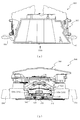
以下、本発明の実施形態について、添付図面を参照して説明する。まず、図1から図35を参照し、第1実施形態として、本発明をパチンコ遊技機(以下、単に「パチンコ機」という)10に適用した場合の一実施形態について説明する。図1は、第1実施形態におけるパチンコ機10の正面図であり、図2はパチンコ機10の遊技盤13の正面図であり、図3はパチンコ機10の背面図である。   Embodiments of the present invention will be described below with reference to the accompanying drawings. First, with reference to FIG. 1 to FIG. 35, an embodiment in which the present invention is applied to a pachinko gaming machine (hereinafter simply referred to as “pachinko machine”) 10 will be described as a first embodiment. 1 is a front view of a pachinko machine 10 according to the first embodiment, FIG. 2 is a front view of a game board 13 of the pachinko machine 10, and FIG. 3 is a rear view of the pachinko machine 10.

図1に示すように、パチンコ機10は、略矩形状に組み合わせた木枠により外殻が形成される外枠11と、その外枠11と略同一の外形形状に形成され外枠11に対して開閉可能に支持された内枠12とを備えている。外枠11には、内枠12を支持するために正面視(図1参照)左側の上下2カ所に金属製のヒンジ18が取り付けられ、そのヒンジ18が設けられた側を開閉の軸として内枠12が正面手前側へ開閉可能に支持されている。   As shown in FIG. 1, the pachinko machine 10 includes an outer frame 11 in which an outer shell is formed by a wooden frame combined in a substantially rectangular shape, and an outer shape that is substantially the same as the outer frame 11. And an inner frame 12 supported to be openable and closable. In order to support the inner frame 12, metal hinges 18 are attached to the outer frame 11 at two upper and lower portions on the left side when viewed from the front (see FIG. 1), and the side on which the hinge 18 is provided is used as an opening / closing axis. The frame 12 is supported so as to be openable and closable to the front front side.

内枠12には、多数の釘や入賞口63,64等を有する遊技盤13(図2参照)が裏面側から着脱可能に装着される。この遊技盤13の前面を球(遊技球)が流下することにより弾球遊技が行われる。なお、内枠12には、球を遊技盤13の前面領域に発射する球発射ユニット112a(図4参照)やその球発射ユニット112aから発射された球を遊技盤13の前面領域まで誘導する発射レール(図示せず)等が取り付けられている。   A game board 13 (see FIG. 2) having a large number of nails, winning holes 63, 64, and the like is detachably mounted on the inner frame 12 from the back side. A ball ball game is played when a ball (game ball) flows down the front of the game board 13. The inner frame 12 has a ball launch unit 112a (see FIG. 4) that launches a ball to the front area of the game board 13 and a launch that guides the ball launched from the ball launch unit 112a to the front area of the game board 13. A rail (not shown) or the like is attached.

内枠12の前面側には、その前面上側を覆う前面枠14と、その下側を覆う下皿ユニット15とが設けられている。前面枠14及び下皿ユニット15を支持するために正面視(図1参照)左側の上下2カ所に金属製のヒンジ19が取り付けられ、そのヒンジ19が設けられた側を開閉の軸として前面枠14及び下皿ユニット15が正面手前側へ開閉可能に支持されている。なお、内枠12の施錠と前面枠14の施錠とは、シリンダ錠20の鍵穴21に専用の鍵を差し込んで所定の操作を行うことでそれぞれ解除される。   On the front side of the inner frame 12, a front frame 14 that covers the upper side of the front surface and a lower dish unit 15 that covers the lower side of the front frame 14 are provided. In order to support the front frame 14 and the lower dish unit 15, metal hinges 19 are attached to two upper and lower portions on the left side when viewed from the front (see FIG. 1), and the side on which the hinges 19 are provided is used as an opening / closing axis. 14 and the lower pan unit 15 are supported so as to be openable and closable toward the front front side. The locking of the inner frame 12 and the locking of the front frame 14 are respectively released by inserting a dedicated key into the key hole 21 of the cylinder lock 20 and performing a predetermined operation.

前面枠14は、装飾用の樹脂部品や電気部品等を組み付けたものであり、その略中央部には略楕円形状に開口形成された窓部14cが設けられている。前面枠14の裏面側には2枚の板ガラスを有するガラスユニット16が配設され、そのガラスユニット16を介して遊技盤13の前面がパチンコ機10の正面側に視認可能となっている。   The front frame 14 is assembled with decorative resin parts, electrical parts, and the like, and a window part 14c that is formed in an approximately elliptical shape is provided at a substantially central part thereof. A glass unit 16 having two plate glasses is disposed on the back side of the front frame 14, and the front surface of the game board 13 can be seen on the front side of the pachinko machine 10 through the glass unit 16.

前面枠14には、球を貯留する上皿17が前方へ張り出して上面を開放した略箱状に形成されており、この上皿17に賞球や貸出球などが排出される。上皿17の底面は正面視(図1参照)右側に下降傾斜して形成され、その傾斜により上皿17に投入された球が球発射ユニット112a(図4参照)へと案内される。また、上皿17の上面には、枠ボタン22が設けられている。この枠ボタン22は、例えば、第3図柄表示装置81(図2参照)で表示される演出のステージを変更したり、スーパーリーチの演出内容を変更したりする場合などに、遊技者により操作される。   On the front frame 14, an upper plate 17 that stores balls is formed in a substantially box shape that protrudes forward and the upper surface is opened, and prize balls and rental balls are discharged to the upper plate 17. The bottom surface of the upper plate 17 is formed to be inclined downward to the right when viewed from the front (see FIG. 1), and the sphere thrown into the upper plate 17 is guided to the ball launch unit 112a (see FIG. 4). A frame button 22 is provided on the upper surface of the upper plate 17. The frame button 22 is operated by the player when, for example, changing the stage of the effect displayed on the third symbol display device 81 (see FIG. 2) or changing the contents of the effect of super reach. The

前面枠14には、その周囲(例えばコーナー部分)に各種ランプ等の発光手段が設けられている。これら発光手段は、大当たり時や所定のリーチ時等における遊技状態の変化に応じて、点灯又は点滅することにより発光態様が変更制御され、遊技中の演出効果を高める役割を果たす。窓部14cの周縁には、LED等の発光手段を内蔵した電飾部29〜33が設けられている。パチンコ機10においては、これら電飾部29〜33が大当たりランプ等の演出ランプとして機能し、大当たり時やリーチ演出時等には内蔵するLEDの点灯や点滅によって各電飾部29〜33が点灯または点滅して、大当たり中である旨、或いは大当たり一歩手前のリーチ中である旨が報知される。また、前面枠14の正面視(図1参照)左上部には、LED等の発光手段が内蔵され賞球の払い出し中とエラー発生時とを表示可能な表示ランプ34が設けられている。   The front frame 14 is provided with light emitting means such as various lamps around it (for example, a corner portion). These light emitting means play a role of enhancing the effect of the game during the game by changing or controlling the light emission mode by turning on or blinking according to the change of the gaming state at the time of big hit or predetermined reach. On the peripheral edge of the window portion 14c, there are provided electric decoration portions 29 to 33 incorporating light emitting means such as LEDs. In the pachinko machine 10, these lighting parts 29 to 33 function as effect lamps such as jackpot lamps, and the lighting parts 29 to 33 are turned on by lighting or blinking of the built-in LEDs at the time of jackpot or reach effects. Alternatively, it blinks to notify that the jackpot is being hit or that the reach is one step before the jackpot. Further, in the upper left part of the front frame 14 as viewed from the front (see FIG. 1), there is provided a display lamp 34 which has built-in light emitting means such as LEDs and can display the payout of a prize ball and when an error occurs.

また、右側の電飾部32下側には、前面枠14の裏面側を視認できるように裏面側より透明樹脂を取り付けて小窓35が形成され、遊技盤13前面の貼着スペースK1(図2参照)に貼付される証紙等がパチンコ機10の前面から視認可能とされている。また、パチンコ機10においては、より煌びやかさを醸し出すために、電飾部29〜33の周りの領域にクロムメッキを施したABS樹脂製のメッキ部材36が取り付けられている。   In addition, a small window 35 is formed by attaching a transparent resin from the back side so that the back side of the front frame 14 can be visually recognized, on the lower side of the right illumination part 32, and a sticking space K1 on the front side of the game board 13 (FIG. 2) can be visually recognized from the front surface of the pachinko machine 10. In addition, in the pachinko machine 10, a plated member 36 made of ABS resin that is chrome-plated is attached to an area around the electric decoration parts 29 to 33 in order to bring out more gorgeousness.

窓部14cの下方には、貸球操作部40が配設されている。貸球操作部40には、度数表示部41と、球貸しボタン42と、返却ボタン43とが設けられている。パチンコ機10の側方に配置されるカードユニット(球貸しユニット)(図示せず)に紙幣やカード等を投入した状態で貸球操作部40が操作されると、その操作に応じて球の貸出が行われる。具体的には、度数表示部41はカード等の残額情報が表示される領域であり、内蔵されたLEDが点灯して残額情報として残額が数字で表示される。球貸しボタン42は、カード等(記録媒体)に記録された情報に基づいて貸出球を得るために操作されるものであり、カード等に残額が存在する限りにおいて貸出球が上皿17に供給される。返却ボタン43は、カードユニットに挿入されたカード等の返却を求める際に操作される。なお、カードユニットを介さずに球貸し装置等から上皿17に球が直接貸し出されるパチンコ機、いわゆる現金機では貸球操作部40が不要となるが、この場合には、貸球操作部40の設置部分に飾りシール等を付加して部品構成は共通のものとしても良い。カードユニットを用いたパチンコ機と現金機との共通化を図ることができる。   A ball rental operation unit 40 is disposed below the window 14c. The ball lending operation unit 40 is provided with a frequency display unit 41, a ball lending button 42, and a return button 43. When the ball lending operation unit 40 is operated in a state where a bill or a card is inserted into a card unit (ball lending unit) (not shown) arranged on the side of the pachinko machine 10, Loans are made. Specifically, the frequency display unit 41 is an area in which the remaining amount information such as a card is displayed, and the built-in LED is lit to display the remaining amount as the remaining amount information. The ball lending button 42 is operated to obtain a lending ball based on information recorded on a card or the like (recording medium), and the lending ball is supplied to the upper plate 17 as long as there is a remaining amount on the card or the like. Is done. The return button 43 is operated when requesting the return of a card or the like inserted into the card unit. In addition, in a pachinko machine in which a ball is lent directly to the upper plate 17 from a ball lending device or the like without using a card unit, a so-called cash machine does not require the ball lending operation unit 40. In this case, the ball lending operation unit 40 It is also possible to add a decorative seal or the like to the installation portion of the parts so that the component configuration is common. A pachinko machine using a card unit and a cash machine can be shared.

上皿17の下側に位置する下皿ユニット15には、その中央部に上皿17に貯留しきれなかった球を貯留するための下皿50が上面を開放した略箱状に形成されている。下皿50の右側には、球を遊技盤13の前面へ打ち込むために遊技者によって操作される操作ハンドル51が配設される。   In the lower plate unit 15 located on the lower side of the upper plate 17, a lower plate 50 for storing a ball that could not be stored in the upper plate 17 is formed in a substantially box shape having an open upper surface. Yes. On the right side of the lower plate 50, an operation handle 51 that is operated by a player to drive a ball into the front surface of the game board 13 is disposed.

操作ハンドル51の内部には、球発射ユニット112aの駆動を許可するためのタッチセンサ51aと、押下操作している期間中には球の発射を停止する発射停止スイッチ51bと、操作ハンドル51の回動操作量(回動位置)を電気抵抗の変化により検出する可変抵抗器(図示せず)などが内蔵されている。操作ハンドル51が遊技者によって右回りに回動操作されると、タッチセンサ51aがオンされると共に可変抵抗器の抵抗値が回動操作量に対応して変化し、その可変抵抗器の抵抗値に対応した強さ(発射強度)で球が発射され、これにより遊技者の操作に対応した飛び量で遊技盤13の前面へ球が打ち込まれる。また、操作ハンドル51が遊技者により操作されていない状態においては、タッチセンサ51aおよび発射停止スイッチ51bがオフとなっている。   Inside the operation handle 51, a touch sensor 51a for permitting driving of the ball launch unit 112a, a launch stop switch 51b for stopping the launch of the ball during the pressing operation, and a rotation of the operation handle 51. A variable resistor (not shown) that detects the amount of movement (rotation position) based on a change in electrical resistance is incorporated. When the operation handle 51 is rotated clockwise by the player, the touch sensor 51a is turned on and the resistance value of the variable resistor changes in accordance with the amount of rotation operation. The resistance value of the variable resistor A ball is fired with a strength corresponding to (shooting strength), and the ball is driven into the front surface of the game board 13 with a jump amount corresponding to the player's operation. Further, when the operation handle 51 is not operated by the player, the touch sensor 51a and the firing stop switch 51b are turned off.

下皿50の正面下方部には、下皿50に貯留された球を下方へ排出する際に操作するための球抜きレバー52が設けられている。この球抜きレバー52は、常時、右方向に付勢されており、その付勢に抗して左方向へスライドさせることにより、下皿50の底面に形成された底面口が開口して、その底面口から球が自然落下して排出される。この球抜きレバー52の操作は、通常、下皿50の下方に下皿50から排出された球を受け取る箱(一般に「千両箱」と称される)を置いた状態で行われる。下皿50の右方には、上述したように操作ハンドル51が配設され、下皿50の左方には灰皿53が取り付けられている。   In the lower part of the front of the lower plate 50, a ball removal lever 52 is provided for operating when the balls stored in the lower plate 50 are discharged downward. The ball removal lever 52 is always urged in the right direction. By sliding the ball release lever 52 in the left direction against the urge, the bottom opening formed in the bottom surface of the lower plate 50 is opened. A ball naturally falls from the bottom opening and is discharged. The operation of the ball removal lever 52 is normally performed in a state where a box (generally referred to as “a thousand box”) for receiving the balls discharged from the lower plate 50 is placed below the lower plate 50. As described above, the operation handle 51 is disposed on the right side of the lower plate 50, and the ashtray 53 is attached on the left side of the lower plate 50.

図2に示すように、遊技盤13は、正面視略正方形状に切削加工したベース板60に、球案内用の多数の釘(図示せず)や風車の他、レール61,62、一般入賞口63、第1入賞口64、第2入賞口640、第一可変入賞装置65、第2可変入賞装置650、スルーゲート67、可変表示装置ユニット80等を組み付けて構成され、その周縁部が内枠12(図1参照)の裏面側に取り付けられる。ベース板60は光透過性の樹脂材料からなり、その正面側からベース板60の背面側に配設された各種構造体を遊技者に視認させることが可能に形成される。一般入賞口63、第1入賞口64、第2入賞口640、第1可変入賞装置65、第2可変入賞装置650、可変表示装置ユニット80は、ルータ加工によってベース板60に形成された貫通穴に配設され、遊技盤13の前面側からタッピングネジ等により固定されている。   As shown in FIG. 2, the game board 13 has a base plate 60 cut into a substantially square shape when viewed from the front, a large number of nails (not shown) for ball guidance, windmills, rails 61 and 62, and general prizes. It is configured by assembling a mouth 63, a first prize opening 64, a second prize opening 640, a first variable prize winning device 65, a second variable prize winning device 650, a through gate 67, a variable display device unit 80, etc. It is attached to the back side of the frame 12 (see FIG. 1). The base plate 60 is made of a light-transmitting resin material and is formed so that the player can visually recognize various structures disposed on the back side of the base plate 60 from the front side. The general winning port 63, the first winning port 64, the second winning port 640, the first variable winning device 65, the second variable winning device 650, and the variable display device unit 80 are formed in through holes formed in the base plate 60 by router processing. And is fixed from the front side of the game board 13 by a tapping screw or the like.

遊技盤13の前面中央部分は、前面枠14の窓部14c(図1参照)を通じて内枠12の前面側から視認することができる。以下に、主に図2を参照して、遊技盤13の構成について説明する。   The front center portion of the game board 13 can be viewed from the front side of the inner frame 12 through the window portion 14c (see FIG. 1) of the front frame 14. The configuration of the game board 13 will be described below mainly with reference to FIG.

遊技盤13の前面には、帯状の金属板を略円弧状に屈曲加工して形成した外レール62が植立され、その外レール62の内側位置には外レール62と同様に帯状の金属板で形成した円弧状の内レール61が植立される。この内レール61と外レール62とにより遊技盤13の前面外周が囲まれ、遊技盤13とガラスユニット16(図1参照)とにより前後が囲まれることにより、遊技盤13の前面には、球の挙動により遊技が行われる遊技領域が形成される。遊技領域は、遊技盤13の前面であって2本のレール61,62とレール間を繋ぐ樹脂製の外縁部材73とにより区画して形成される領域(入賞口等が配設され、発射された球が流下する領域)である。   An outer rail 62 formed by bending a strip-shaped metal plate into a substantially arc shape is planted on the front surface of the game board 13, and the strip-shaped metal plate is located on the inner side of the outer rail 62 in the same manner as the outer rail 62. The arc-shaped inner rail 61 formed by the above is planted. The inner rail 61 and the outer rail 62 surround the outer periphery of the front surface of the game board 13, and the game board 13 and the glass unit 16 (see FIG. 1) surround the front and rear. A game area in which a game is played is formed by the behavior of. The game area is an area formed on the front surface of the game board 13 and defined by two rails 61 and 62 and a resin outer edge member 73 that connects the rails (a winning opening is provided and fired). Area where the falling sphere flows).

2本のレール61,62は、球発射ユニット112a(図4参照)から発射された球を遊技盤13上部へ案内するために設けられたものである。内レール61の先端部分(図2の左上部)には戻り球防止部材68が取り付けられ、一旦、遊技盤13の上部へ案内された球が再度球案内通路内に戻ってしまうといった事態が防止される。外レール62の先端部(図2の右上部)には、球の最大飛翔部分に対応する位置に返しゴム69が取り付けられ、所定以上の勢いで発射された球は、返しゴム69に当たって、勢いが減衰されつつ中央部側へ跳ね返される。   The two rails 61 and 62 are provided to guide the ball fired from the ball launch unit 112a (see FIG. 4) to the upper part of the game board 13. A return ball preventing member 68 is attached to the front end portion of the inner rail 61 (upper left portion in FIG. 2) to prevent the ball once guided to the upper portion of the game board 13 from returning to the ball guide path again. Is done. A return rubber 69 is attached to the tip of the outer rail 62 (upper right part in FIG. 2) at a position corresponding to the maximum flying portion of the sphere. Is bounced back to the center while being attenuated.

遊技領域の正面視左側下部(図2の左側下部)には、発光手段である複数のLED及び7セグメント表示器を備える第1図柄表示装置37A,37Bが配設されている。第1図柄表示装置37A,37Bは、主制御装置110(図4参照)で行われる各制御に応じた表示がなされるものであり、主にパチンコ機10の遊技状態の表示が行われる。本実施形態では、第1図柄表示装置37A,37Bは、球が、第1入賞口64へ入賞したか、第2入賞口640へ入賞したかに応じて使い分けられるように構成されている。具体的には、球が、第1入賞口64へ入賞した場合には、第1図柄表示装置37Aが作動し、一方で、球が、第2入賞口640へ入賞した場合には、第1図柄表示装置37Bが作動するように構成されている。   First symbol display devices 37A and 37B each having a plurality of LEDs and a 7-segment display as light emitting means are disposed in the lower left portion of the game area when viewed from the front (lower left portion in FIG. 2). The first symbol display devices 37A and 37B display according to each control performed by the main control device 110 (see FIG. 4), and mainly display the gaming state of the pachinko machine 10. In the present embodiment, the first symbol display devices 37 </ b> A and 37 </ b> B are configured to be selectively used depending on whether the ball has won the first prize opening 64 or the second prize opening 640. Specifically, when the ball wins the first winning opening 64, the first symbol display device 37A operates, while when the ball wins the second winning opening 640, the first symbol display device 37A operates. The symbol display device 37B is configured to operate.

また、第1図柄表示装置37A,37Bは、LEDにより、パチンコ機10が確変中か時短中か通常中であるかを点灯状態により示したり、変動中であるか否かを点灯状態により示したり、停止図柄が確変大当たりに対応した図柄か普通大当たりに対応した図柄か外れ図柄であるかを点灯状態により示したり、保留球数を点灯状態により示すと共に、7セグメント表示装置により、大当たり中のラウンド数やエラー表示を行う。なお、複数のLEDは、それぞれのLEDの発光色(例えば、赤、緑、青)が異なるよう構成され、その発光色の組み合わせにより、少ないLEDでパチンコ機10の各種遊技状態を示唆することができる。   In addition, the first symbol display devices 37A and 37B indicate, by means of LEDs, whether the pachinko machine 10 is in the process of changing the probability, in the short time, or in the normal state by a lighting state, or whether the pachinko machine 10 is changing or not by a lighting state. , Indicating whether the stop symbol is a symbol corresponding to a probable jackpot, a symbol corresponding to a normal jackpot, or a symbol that is out of place by a lighting state, indicating the number of held balls by a lighting state, and a 7-segment display device, Displays numbers and errors. The plurality of LEDs are configured to have different emission colors (for example, red, green, and blue) of each LED, and the combination of the emission colors may suggest various gaming states of the pachinko machine 10 with a small number of LEDs. it can.

尚、本パチンコ機10では、第1入賞口64及び第2入賞口640へ入賞があったことを契機として抽選が行われる。パチンコ機10は、その抽選において、大当たりか否かの当否判定(大当たり抽選)を行うと共に、大当たりと判定した場合はその大当たり種別の判定も行う。ここで判定される大当たり種別としては、15R確変大当たり、4R確変大当たり、15R通常大当たりが用意されている。第1図柄表示装置37A,37Bには、変動終了後の停止図柄として抽選の結果が大当たりであるか否かが示されるだけでなく、大当たりである場合はその大当たり種別に応じた図柄が示される。   In the present pachinko machine 10, a lottery is performed in response to winning of the first winning port 64 and the second winning port 640. In the lottery, the pachinko machine 10 determines whether or not it is a big hit (big hit lottery), and also determines the type of the big hit if it is determined to be a big hit. As the jackpot type determined here, 15R probability variation jackpot, 4R probability variation jackpot, and 15R normal jackpot are prepared. The first symbol display devices 37A and 37B not only indicate whether or not the lottery result is a jackpot as a stop symbol after the end of the variation, but if it is a jackpot, a symbol corresponding to the jackpot type is displayed. .

ここで、「15R確変大当たり」とは、最大ラウンド数が15ラウンドの大当たりの後に高確率状態へ移行する確変大当たりのことであり、「4R確変大当たり」とは、最大ラウンド数が4ラウンドの大当たりの後に高確率状態へ移行する確変大当たりのことである。また、「15R通常大当たり」は、最大ラウンド数が15ラウンドの大当たりの後に、低確率状態へ移行すると共に、所定の変動回数の間(例えば、100変動回数)は時短状態となる大当たりのことである。   Here, the “15R probability variation jackpot” is a probability variation jackpot in which the maximum number of rounds shifts to a high probability state after a jackpot of 15 rounds, and “4R probability variation jackpot” is a jackpot with a maximum number of rounds of four. It is a probabilistic jackpot that shifts to a high probability state after. In addition, “15R normal jackpot” is a jackpot that shifts to a low probability state after the maximum number of rounds of 15 rounds and hits a short time during a predetermined number of fluctuations (for example, 100 fluctuations). is there.

また、「高確率状態」とは、大当たり終了後に付加価値としてその後の大当たり確率がアップした状態、いわゆる確率変動中(確変中)の時をいい、換言すれば、特別遊技状態へ移行し易い遊技の状態のことである。本実施形態における高確率状態(確変中)は、後述する第2図柄の当たり確率がアップして第2入賞口640へ球が入賞し易い遊技の状態を含む。「低確率状態」とは、確変中でない時をいい、大当たり確率が通常の状態、即ち、確変の時より大当たり確率が低い状態をいう。また、「低確率状態」のうちの時短状態(時短中)とは、大当たり確率が通常の状態であると共に、大当たり確率がそのままで第2図柄の当たり確率のみがアップして第2入賞口640へ球が入賞し易い遊技の状態のことをいう。一方、パチンコ機10が通常中とは、確変中でも時短中でもない遊技の状態(大当たり確率も第2図柄の当たり確率もアップしていない状態)である。   In addition, the “high probability state” means a state in which the jackpot probability thereafter increases as an added value after the jackpot ends, that is, when the probability change is in progress (probability change), in other words, a game that easily shifts to the special game state. It is a state of. The high probability state (during probability change) in the present embodiment includes a game state in which the hit probability of the second symbol, which will be described later, is increased and the ball is likely to win the second winning opening 640. The “low probability state” refers to a time when the probability of jackpot change is not occurring, and a state where the jackpot probability is normal, that is, a state where the jackpot probability is lower than that at the time of probability change. The short time state (short time medium) of the “low probability state” means that the jackpot probability is a normal state, and the jackpot probability remains as it is, and only the hit probability of the second symbol is increased, and the second prize opening 640 is obtained. It means the state of the game where the ball is easy to win. On the other hand, when the pachinko machine 10 is in a normal state is a game state (a state where neither the big hit probability nor the second symbol hit probability is increased) which is neither probabilistic nor short in time.

確変中や時短中は、第2図柄の当たり確率がアップするだけではなく、第2入賞口640に付随する電動役物640aが開放される時間も変更され、通常中と比して長い時間が設定される。電動役物640aが開放された状態(開放状態)にある場合は、その電動役物640aが閉鎖された状態(閉鎖状態)にある場合と比して、第2入賞口640へ球が入賞しやすい状態となる。よって、確変中や時短中は、第2入賞口640へ球が入賞し易い状態となり、大当たり抽選が行われる回数を増やすことができる。   During probability change and time reduction, not only does the probability of winning the second symbol increase, but also the time for opening the electric accessory 640a associated with the second prize opening 640 is changed, and the time is longer than normal. Is set. When the electric accessory 640a is in the opened state (open state), the ball wins the second winning opening 640 as compared to the case where the electric accessory 640a is in the closed state (closed state). Easy state. Therefore, during the probability change or the short time, it becomes easy for the ball to win the second winning opening 640, and the number of jackpot lotteries can be increased.

なお、確変中や時短中において、第2入賞口640に付随する電動役物640aの開放時間を変更するのではなく、または、その開放時間を変更することに加えて、1回の当たりで電動役物640aが開放する回数を通常中よりも増やす変更を行うものとしてもよい。また、確変中や時短中において、第2図柄の当たり確率は変更せず、第2入賞口640に付随する電動役物640aが開放される時間および1回の当たりで電動役物640aが開放する回数の少なくとも一方を変更するものとしてもよい。また、確変中や時短中において、第2入賞口640に付随する電動役物640aが開放される時間や、1回の当たりで電動役物640aを開放する回数はせず、第2図柄の当たり確率だけを、通常中と比してアップするよう変更するものであってもよい。   In addition, during the probability change or during the short time, it is not necessary to change the opening time of the electric accessory 640a associated with the second prize opening 640, or in addition to changing the opening time, It is good also as what changes the frequency | count that the accessory 640a opens more than usual. In addition, the probability of winning the second symbol is not changed during the probability change or in the short time, and the electric accessory 640a is released at the time when the electric accessory 640a associated with the second winning opening 640 is opened and once. It is good also as what changes at least one of the frequency | counts. In addition, during the probability change or in the short time, the time of opening the electric accessory 640a associated with the second winning opening 640 or the number of times of opening the electric accessory 640a per time is not counted, and the second symbol hit Only the probability may be changed so as to increase compared to the normal rate.

遊技領域には、球が入賞することにより5個から15個の球が賞球として払い出される複数の一般入賞口63が配設されている。また、遊技領域の中央部分には、可変表示装置ユニット80が配設されている。可変表示装置ユニット80には、第1入賞口64及び第2入賞口640への入賞(始動入賞)をトリガとして、第1図柄表示装置37A,37Bにおける変動表示と同期させながら、第3図柄の変動表示を行う液晶ディスプレイ(以下単に「表示装置」と略す)で構成された第3図柄表示装置81と、スルーゲート67の球の通過をトリガとして第2図柄を変動表示するLEDで構成される第2図柄表示装置(図示せず)とが設けられている。また、可変表示装置ユニット80には、第3図柄表示装置81の外周を囲むようにして、センターフレーム86が配設されている。   The game area is provided with a plurality of general winning ports 63 through which 5 to 15 balls are paid out as winning balls when the balls win. In addition, a variable display device unit 80 is disposed in the central portion of the game area. The variable display device unit 80 is synchronized with the variable display on the first symbol display devices 37A and 37B by using a winning (start winning) at the first winning port 64 and the second winning port 640 as a trigger. It is composed of a third symbol display device 81 composed of a liquid crystal display (hereinafter simply referred to as “display device”) that performs variable display, and an LED that displays the second symbol in a variable manner with the passage of a sphere of the through gate 67 as a trigger. A second symbol display device (not shown) is provided. The variable display device unit 80 is provided with a center frame 86 so as to surround the outer periphery of the third symbol display device 81.

第3図柄表示装置81は9インチサイズの大型の液晶ディスプレイで構成されるものであり、表示制御装置114(図4参照)によって表示内容が制御されることにより、例えば上、中及び下の3つの図柄列が表示される。各図柄列は複数の図柄(第3図柄)によって構成され、これらの第3図柄が図柄列毎に横スクロールして第3図柄表示装置81の表示画面上にて第3図柄が可変表示されるようになっている。本実施形態の第3図柄表示装置81は、主制御装置110(図4参照)の制御に伴った遊技状態の表示が第1図柄表示装置37A,37Bで行われるのに対して、その第1図柄表示装置37A,37Bの表示に応じた装飾的な表示を行うものである。なお、表示装置に代えて、例えばリール等を用いて第3図柄表示装置81を構成するようにしても良い。   The third symbol display device 81 is constituted by a large 9-inch liquid crystal display, and the display content is controlled by the display control device 114 (see FIG. 4). One symbol row is displayed. Each symbol row is composed of a plurality of symbols (third symbol). These third symbols are horizontally scrolled for each symbol column, and the third symbol is variably displayed on the display screen of the third symbol display device 81. It is like that. In the third symbol display device 81 of the present embodiment, the game state is displayed on the first symbol display devices 37A and 37B in accordance with the control of the main control device 110 (see FIG. 4). The decorative display according to the display of the symbol display devices 37A and 37B is performed. Instead of the display device, the third symbol display device 81 may be configured using, for example, a reel.

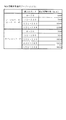
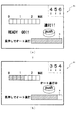
第2図柄表示装置は、球がスルーゲート67を通過する毎に表示図柄(第2図柄(図示せず))としての「○」の図柄と「×」の図柄とを所定時間交互に点灯させる変動表示を行うものである。パチンコ機10では、球がスルーゲート67を通過したことが検出されると、当たり抽選が行われる。その当たり抽選の結果、当たりであれば、第2図柄表示装置において、第2図柄の変動表示後に「○」の図柄が停止表示される。また、当たり抽選の結果、外れであれば、第2図柄表示装置において、第3図柄の変動表示後に「×」の図柄が停止表示される。   Each time the sphere passes through the through gate 67, the second symbol display device alternately turns on the symbol “◯” and the symbol “X” as a display symbol (second symbol (not shown)) for a predetermined time. A variable display is performed. In the pachinko machine 10, when it is detected that the ball has passed through the through gate 67, a winning lottery is performed. As a result of the winning lottery, if the winning symbol is a winning symbol, the symbol “◯” is stopped and displayed on the second symbol display device after the variation of the second symbol is displayed. Further, if the winning lottery results, the symbol of “x” is stopped and displayed on the second symbol display device after the variation of the third symbol is displayed.

パチンコ機10は、第2図柄表示装置における変動表示が所定図柄(本実施形態においては「○」の図柄)で停止した場合に、第2入賞口640に付随された電動役物640aが所定時間だけ作動状態となる(開放される)よう構成されている。   In the pachinko machine 10, when the variable display on the second symbol display device stops at a predetermined symbol (in this embodiment, a symbol “◯”), the electric accessory 640a attached to the second winning opening 640 is displayed for a predetermined time. It is configured to be in an activated state (opened) only.

第2図柄の変動表示にかかる時間は、遊技状態が通常中の場合よりも、確変中または時短中の方が短くなるように設定される。これにより、確変中および時短中は、第2図柄の変動表示が短い時間で行われるので、当たり抽選を通常中よりも多く行うことができる。よって、当たり抽選において当たりとなる機会が増えるので、第2入賞口640の電動役物640aが開放状態となる機会を遊技者に多く与えることができる。よって、確変中および時短中は、第2入賞口640へ球が入賞しやすい状態とすることができる。   The time required for the variable display of the second symbol is set to be shorter during the probability change or during the shorter time than when the game state is normal. As a result, during the probability change and during the time reduction, since the variation display of the second symbol is performed in a short time, the winning lottery can be performed more than during normal. Therefore, since the chance of winning in the winning lottery increases, it is possible to give the player a lot of opportunities for the electric winning component 640a of the second winning opening 640 to be in an open state. Therefore, it is possible to make it easier for the ball to win the second winning opening 640 during the probability change and during the short time.

なお、確変中または時短中において、当たり確率を高める、1回に当たりに対する電動役物640aの開放時間や開放回数を増やすなど、その他の方法によっても、確変中または時短中に第2入賞口640へ球が入賞しやすい状態としている場合は、第2図柄の変動表示にかかる時間を遊技状態にかかわらず一定としてもよい。一方、第2図柄の変動表示にかかる時間を、確変中または時短中において通常中よりも短く設定する場合は、当たり確率を遊技状態にかかわらず一定にしてもよいし、また、1回の当たりに対する電動役物640aの開放時間や開放回数を遊技状態にかかわらず一定にしてもよい。   It is to be noted that the probability of winning is increased during probability change or time reduction, and other methods such as increasing the opening time and the number of times of opening of the electric accessory 640a per hit are also used to reach the second prize opening 640 during probability change or time reduction. When the ball is in a state where it is easy to win, the time required for the variable display of the second symbol may be constant regardless of the gaming state. On the other hand, when the time required for displaying the variation of the second symbol is set shorter than normal during probability change or short time, the winning probability may be constant regardless of the gaming state, The opening time and the number of opening times of the electric accessory 640a may be constant regardless of the gaming state.

スルーゲート67は、可変表示装置ユニット80の下側の領域における右方において遊技盤に組み付けられ、遊技盤に発射された球のうち、遊技盤の右方を流下する球の一部が通過可能に構成されている。スルーゲート67を球が通過すると、第2図柄の当たり抽選が行われる。当たり抽選の後、第2図柄表示装置にて変動表示を行い、当たり抽選の結果が当たりであれば、変動表示の停止図柄として「○」の図柄を表示し、当たり抽選の結果が外れであれば、変動表示の停止図柄として「×」の図柄を表示する。   The through gate 67 is assembled to the game board on the right side in the lower area of the variable display device unit 80, and a part of the ball flowing down to the right side of the game board can pass through the balls launched to the game board. It is configured. When the ball passes through the through gate 67, a winning lottery of the second symbol is performed. After winning the lottery, the 2nd symbol display device displays a variation, and if the winning lottery results, the symbol “○” is displayed as the variable display stop symbol, and the winning lottery result may be off For example, the symbol “x” is displayed as the stop symbol of the variable display.

球のスルーゲート67の通過回数は、合計で最大4回まで保留され、その保留球数が上述した第1図柄表示装置37A,37Bにより表示されると共に第2図柄保留ランプ(図示せず)においても点灯表示される。第2図柄保留ランプは、最大保留数分の4つ設けられ、第3図柄表示装置81の下方に左右対称に配設されている。   The total number of passes through the through-gate 67 of the sphere is held up to a maximum of 4 times, and the number of held balls is displayed by the above-described first symbol display devices 37A and 37B and at the second symbol hold lamp (not shown). Is also displayed. Four second symbol holding lamps are provided for the maximum number of holdings, and are arranged symmetrically below the third symbol display device 81.

なお、第2図柄の変動表示は、本実施形態のように、第2図柄表示装置において複数のランプの点灯と非点灯を切り換えることにより行うものの他、第1図柄表示装置37A,37B及び第3図柄表示装置81の一部を使用して行うようにしても良い。同様に、第2図柄保留ランプの点灯を第3図柄表示装置81の一部で行うようにしても良い。また、スルーゲート67の球の通過に対する最大保留球数は4回に限定されるものでなく、3回以下、又は、5回以上の回数(例えば、8回)に設定しても良い。また、スルーゲート67の組み付け数は1つに限定されるものではなく、複数(例えば、2つ)であっても良い。また、スルーゲート67の組み付け位置は可変表示装置ユニット80の右方に限定されるものではなく、例えば、可変表示装置ユニット80の左方でも良い。また、第1図柄表示装置37A,37Bにより保留球数が示されるので、第2図柄保留ランプにより点灯表示を行わないものとしてもよい。   Note that the variable display of the second symbol is performed by switching between lighting and non-lighting of a plurality of lamps in the second symbol display device as in the present embodiment, as well as the first symbol display devices 37A, 37B and the third symbol. A part of the symbol display device 81 may be used. Similarly, the second symbol holding lamp may be turned on by a part of the third symbol display device 81. Further, the maximum number of balls held for passing through the ball of the through gate 67 is not limited to four times, and may be set to three times or less, or five times or more (for example, eight times). Further, the number of through gates 67 to be assembled is not limited to one, and may be plural (for example, two). Further, the assembly position of the through gate 67 is not limited to the right side of the variable display device unit 80, and may be the left side of the variable display device unit 80, for example. In addition, since the number of reserved balls is indicated by the first symbol display devices 37A and 37B, the second symbol hold lamp may not perform lighting display.

可変表示装置ユニット80の下方には、球が入賞し得る第1入賞口64が配設されている。この第1入賞口64へ球が入賞すると遊技盤13の裏面側に設けられる第1入賞口スイッチ(図示せず)がオンとなり、その第1入賞口スイッチのオンに起因して主制御装置110(図4参照)で大当たりの抽選がなされ、その抽選結果に応じた表示が第1図柄表示装置37Aで示される。   Below the variable display unit 80, a first winning port 64 through which a ball can win is disposed. When a ball wins the first winning port 64, a first winning port switch (not shown) provided on the back side of the game board 13 is turned on, and the main controller 110 is caused by the first winning port switch being turned on. A jackpot lottery is made (see FIG. 4), and a display corresponding to the lottery result is shown on the first symbol display device 37A.

一方、第1入賞口64の正面視右方には、球が入賞し得る第2入賞口640が配設されている。この第2入賞口640へ球が入賞すると遊技盤13の裏面側に設けられる第2入賞口スイッチ(図示せず)がオンとなり、その第2入賞口スイッチのオンに起因して主制御装置110(図4参照)で大当たりの抽選がなされ、その抽選結果に応じた表示が第1図柄表示装置37Bで示される。   On the other hand, a second winning port 640 through which a ball can win is disposed on the right side of the first winning port 64 in front view. When a ball wins the second prize opening 640, a second prize opening switch (not shown) provided on the back side of the game board 13 is turned on, and the main controller 110 is caused by the second prize opening switch being turned on. A jackpot lottery is performed (see FIG. 4), and a display corresponding to the lottery result is shown on the first symbol display device 37B.

また、第1入賞口64および第2入賞口640は、それぞれ、球が入賞すると5個の球が賞球として払い出される入賞口の1つにもなっている。なお、本実施形態においては、第1入賞口64へ球が入賞した場合に払い出される賞球数と第2入賞口640へ球が入賞した場合に払い出される賞球数とを同じに構成したが、第1入賞口64へ球が入賞した場合に払い出される賞球数と第2入賞口640へ球が入賞した場合に払い出される賞球数とを異なる数、例えば、第1入賞口64へ球が入賞した場合に払い出される賞球数を3個とし、第2入賞口640へ球が入賞した場合に払い出される賞球数を5個として構成してもよい。   Each of the first winning port 64 and the second winning port 640 is also one of winning ports from which five balls are paid out as winning balls when a ball is won. In the present embodiment, the number of prize balls to be paid out when a ball wins the first prize opening 64 and the number of prize balls to be paid out when a ball wins the second prize slot 640 are configured to be the same. The number of prize balls to be paid out when a ball wins the first prize opening 64 is different from the number of prize balls to be paid out when a ball wins to the second prize opening 640, for example, the ball to the first prize opening 64 The number of prize balls to be paid out when a prize is won may be three, and the number of prize balls to be paid out when a ball wins the second prize opening 640 may be five.

第2入賞口640には電動役物640aが付随されている。この電動役物640aは開閉可能に構成されており、通常は電動役物640aが閉鎖状態(縮小状態)となって、球が第2入賞口640へ入賞しにくい状態となっている。一方、スルーゲート67への球の通過を契機として行われる第2図柄の変動表示の結果、「○」の図柄が第2図柄表示装置に表示された場合、電動役物640aが開放状態(拡大状態)となり、球が第2入賞口640へ入賞しやすい状態となる。   The second winning opening 640 is accompanied by an electric accessory 640a. The electric accessory 640a is configured to be openable and closable. Normally, the electric accessory 640a is in a closed state (reduced state), and it is difficult for the ball to win the second winning opening 640. On the other hand, when the symbol “◯” is displayed on the second symbol display device as a result of the variation display of the second symbol that is triggered by the passage of the ball to the through gate 67, the electric accessory 640a is in an open state (enlarged) State), and the ball is likely to win the second winning opening 640.

上述した通り、確変中および時短中は、通常中と比して第2図柄の当たり確率が高く、また、第2図柄の変動表示にかかる時間も短いので、第2図柄の変動表示において「○」の図柄が表示され易くなって、電動役物640aが開放状態(拡大状態)となる回数が増える。更に、確変中および時短中は、電動役物640aが開放される時間も、通常中より長くなる。よって、確変中および時短中は、通常時と比して、第2入賞口640へ球が入賞しやすい状態を作ることができる。   As described above, the probability of hitting the second symbol is higher than that during normal change during the probability change and the short time, and the time required for the variation display of the second symbol is short. "Is easily displayed, and the number of times that the electric accessory 640a is opened (enlarged) is increased. Further, during the probability change and the time reduction, the time for opening the electric accessory 640a also becomes longer than during the normal time. Therefore, it is possible to create a state where the ball is likely to win the second winning opening 640 during the probability change and during the short time compared to the normal time.

ここで、第1入賞口64に球が入賞した場合と第2入賞口640へ球が入賞した場合とで、大当たりとなる確率は、低確率状態であっても高確率状態でも同一である。しかしながら、大当たりとなった場合に選定される大当たりの種別として15R確変大当たりとなる確率は、第2入賞口640へ球が入賞した場合のほうが第1入賞口64へ球が入賞した場合よりも高く設定されている。一方、第1入賞口64は、第2入賞口640にあるような電動役物は有しておらず、球が常時入賞可能な状態となっている。   Here, the probability of winning a big hit is the same in both the low probability state and the high probability state when the ball wins the first winning port 64 and when the ball wins the second winning port 640. However, the probability that a 15R probability variation jackpot is selected as the jackpot type selected when the jackpot is won is higher when the ball wins the second winning slot 640 than when the ball wins the first winning slot 64. Is set. On the other hand, the first winning port 64 does not have an electric accessory as in the second winning port 640, and is in a state where the ball can always win.

よって、通常中においては、第2入賞口640に付随する電動役物が閉鎖状態にある場合が多く、第2入賞口640に入賞しづらいので、電動役物のない第1入賞口64へ向けて、可変表示装置ユニット80の左方を球が通過するように球を発射し(所謂「左打ち」)、第1入賞口64への入賞によって大当たり抽選の機会を多く得て、大当たりとなることを狙った方が、遊技者にとって有利となる。   Therefore, during normal times, the electric winnings associated with the second winning opening 640 are often in a closed state, and it is difficult to win the second winning opening 640. Then, the ball is fired so that the ball passes to the left of the variable display device unit 80 (so-called “left-handed”), and a lot of opportunities for lottery wins are obtained by winning at the first winning opening 64, and the jackpot It is advantageous for the player to aim for this.

一方、確変中や時短中は、スルーゲート67に球を通過させることで、第2入賞口640に付随する電動役物640aが開放状態となりやすく、第2入賞口640に入賞しやすい状態であるので、第2入賞口640へ向けて、可変表示装置80の右方を球が通過するように球を発射し(所謂「右打ち」)、スルーゲート67を通過させて電動役物を開放状態にすると共に、第2入賞口640への入賞によって15R確変大当たりとなることを狙った方が、遊技者にとって有利となる。   On the other hand, during the probability change and the shortage of time, by passing the ball through the through gate 67, the electric accessory 640a associated with the second winning opening 640 is likely to be in an open state, and it is easy to win the second winning opening 640. Therefore, the ball is fired toward the second prize opening 640 so that the ball passes the right side of the variable display device 80 (so-called “right-handed”), and is passed through the through gate 67 to open the electric accessory. In addition, it is more advantageous for the player to aim for a 15R probability variation jackpot by winning the second winning opening 640.

このように、本実施形態のパチンコ機10は、パチンコ機10の遊技状態(確変中であるか、時短中であるか、通常中であるか)に応じて、遊技者に対し、球の発射の仕方を「左打ち」と「右打ち」とに変えさせることができる。よって、遊技者に対して、球の打ち方に変化をもたらすことができるので、遊技を楽しませることができる。   As described above, the pachinko machine 10 according to the present embodiment launches a ball to the player in accordance with the gaming state of the pachinko machine 10 (whether it is probable, short, or normal). Can be changed between “left-handed” and “right-handed”. Thus, the player can be changed in the way the ball is hit, so that the game can be enjoyed.

第1入賞口64の下方右側には第1可変入賞装置65が配設されており、その略中央部分に横長矩形状の第1特定入賞口(大開放口)65aが設けられている。また、第1入賞口64の下方左側には第2可変入賞装置650が配設されており、その略中央部分に他の入賞口63,64,640と同程度の大きさの円形形状からなる第2特定入賞口650aが設けられている。パチンコ機10においては、第1入賞口64又は第2入賞口640への入賞に起因して行われた大当たり抽選が大当たりとなると、所定時間(変動時間)が経過した後に、大当たりの停止図柄となるよう第1図柄表示装置37A又は第1図柄表示装置37Bを点灯させると共に、その大当たりに対応した停止図柄を第3図柄表示装置81に表示させて、大当たりの発生が示される。その後、球が入賞し易い特別遊技状態(大当たり)に遊技状態が遷移する。この特別遊技状態として、通常時には閉鎖されている特定入賞口65a,650aが、所定時間(例えば、30秒経過するまで、或いは、球が10個入賞するまで)開放される。   A first variable winning device 65 is disposed on the lower right side of the first winning port 64, and a horizontally elongated first specific winning port (large opening port) 65a is provided at a substantially central portion thereof. Further, a second variable winning device 650 is disposed on the lower left side of the first winning port 64, and has a circular shape having the same size as the other winning ports 63, 64, and 640 at a substantially central portion thereof. A second specific winning opening 650a is provided. In the pachinko machine 10, when the jackpot lottery performed due to the winning at the first winning port 64 or the second winning port 640 becomes a jackpot, after a predetermined time (variable time) has passed, The first symbol display device 37A or the first symbol display device 37B is turned on, and a stop symbol corresponding to the jackpot is displayed on the third symbol display device 81 to indicate the occurrence of the jackpot. Thereafter, the gaming state transitions to a special gaming state (big hit) where the ball is easy to win. As this special gaming state, the special winning openings 65a and 650a that are normally closed are opened for a predetermined time (for example, until 30 seconds have elapsed or 10 balls have been won).

この特定入賞口65a,650aは、所定時間が経過すると閉鎖され、その閉鎖後、再度、その特定入賞口65a,650aが所定時間開放される。この特定入賞口65a,650aの開閉動作は、最高で例えば15回(15ラウンド)繰り返し可能にされている。この開閉動作が行われている状態が、遊技者にとって有利な特別遊技状態の一形態であり、遊技者には、遊技上の価値(遊技価値)の付与として通常時より多量の賞球の払い出しが行われる。   The specific winning ports 65a and 650a are closed when a predetermined time elapses, and after the closing, the specific winning ports 65a and 650a are opened again for a predetermined time. The opening / closing operation of the specific winning ports 65a and 650a can be repeated up to 15 times (15 rounds), for example. The state in which the opening / closing operation is performed is a form of a special gaming state advantageous to the player, and the player is given out a larger amount of prize balls than usual in order to give a gaming value (game value). Is done.

第1可変入賞装置65は、具体的には、第1特定入賞口65aを覆う横長矩形状の開閉板と、その開閉板の下辺を軸として前方側に開閉駆動するための大開放口ソレノイド(図示せず)とを備えている。第1特定入賞口65aは、通常時は、球が入賞できないか又は入賞し難い閉状態になっている。大当たりの際には大開放口ソレノイドを駆動して開閉板を前面下側に傾倒し、球が第1特定入賞口65aに入賞しやすい開状態を一時的に形成し、その開状態と通常時の閉状態との状態を交互に繰り返すように作動する。   Specifically, the first variable winning device 65 includes a horizontally-long rectangular opening / closing plate covering the first specific winning opening 65a, and a large opening solenoid for driving the opening / closing operation forward with the lower side of the opening / closing plate as an axis. (Not shown). The first specific winning opening 65a is normally in a closed state where the ball cannot win or is difficult to win. In the case of a big win, the large opening opening solenoid is driven to tilt the opening / closing plate downward, and the ball is temporarily formed in an open state in which it is easy to win the first specific winning opening 65a. It operates so as to alternately repeat the closed state and the closed state.

第2可変入賞装置650は、具体的には、第2特定入賞口650aへ球を案内する案内路と、その案内路の第2特定入賞口650a側とは反対側となる開口部である開口651と、その開口651の開放および閉鎖を行うための駆動役物650bと、その駆動役物650bを開口651の下辺を軸に左右方向に開閉駆動するための小開放口ソレノイド(図示せず)とを備えている。第2特定入賞口650aは、通常時は、球が入賞できないか又は入賞し難い閉状態になっている。大当たりの際には小開放口ソレノイドを駆動して駆動役物650bを右方に傾倒し、球が第2特定入賞口650aに入賞しやすい開状態を一時的に形成し、その開状態と通常時の閉状態との状態を交互に繰り返すように作動する。   Specifically, the second variable winning device 650 is an opening that is a guide path that guides the ball to the second specific winning port 650a and an opening that is on the opposite side of the guide path from the second specific winning port 650a side. 651, a driving member 650b for opening and closing the opening 651, and a small opening solenoid (not shown) for driving the driving member 650b to open and close in the horizontal direction about the lower side of the opening 651 And. The second specific winning opening 650a is normally in a closed state where the ball cannot win or is difficult to win. In the case of a big hit, the small opening opening solenoid is driven to tilt the driving tool 650b to the right, and an open state in which the ball is likely to win the second specific winning opening 650a is temporarily formed. It operates so as to alternately repeat the state of closed time.

なお、上記した形態に特別遊技状態は限定されるものではない。特定入賞口65a,650aとは別に開閉される大開放口を遊技領域に設け、第1図柄表示装置37A,37Bにおいて大当たりに対応したLEDが点灯した場合に、特定入賞口65a,650aが所定時間開放され、その特定入賞口65a,650aの開放中に、球が特定入賞口65a,650a内へ入賞することを契機として特定入賞口65a,650aとは別に設けられた大開放口が所定時間、所定回数開放される遊技状態を特別遊技状態として形成するようにしても良い。また、特定入賞口65a,650aは1つに限るものではなく、1つ若しくは2以上の複数(例えば3つ)を配置しても良く、また配置位置も第1入賞口64の下方右側や、第1入賞口64の下方左側に限らず、例えば、可変表示装置ユニット80の左方でも良い。   Note that the special gaming state is not limited to the above-described form. When the game area is provided with a large opening that is opened and closed separately from the specific winning openings 65a and 650a, and the LED corresponding to the jackpot is turned on in the first symbol display devices 37A and 37B, the specific winning openings 65a and 650a are set for a predetermined time. A large opening provided separately from the specific winning ports 65a and 650a is triggered for a predetermined time when the ball wins into the specific winning ports 65a and 650a while the specific winning ports 65a and 650a are opened. A gaming state that is released a predetermined number of times may be formed as a special gaming state. Further, the number of the specific winning openings 65a and 650a is not limited to one, and one or a plurality of plural (for example, three) may be arranged, and the arrangement position is the lower right side of the first winning opening 64, For example, the left side of the variable display unit 80 is not limited to the lower left side of the first winning port 64.

遊技盤13の下側における右隅部には、証紙や識別ラベル等を貼着するための貼着スペースK1が設けられ、貼着スペースK1に貼られた証紙等は、前面枠14の小窓35(図1参照)を通じて視認することができる。   A sticking space K1 for sticking a certificate paper, an identification label or the like is provided at the lower right corner of the game board 13, and the certificate paper or the like attached to the sticking space K1 is a small window of the front frame 14. 35 (see FIG. 1).

遊技盤13には、第1アウト口71及び第2アウト口72が設けられている。遊技領域を流下する球であって、いずれの入賞口63,64,65a,640,650aにも入賞しなかった球は、第1アウト口71又は第2アウト口72を通って図示しない球排出路へと案内される。第1アウト口71は、第1入賞口64の下方に配設される一方、第2アウト口72は、第2特定入賞口650aの左側に配設される。即ち、第2アウト口72は、第2特定入賞口650aを挟んで第1アウト口71の反対側に配設される。   The game board 13 is provided with a first out port 71 and a second out port 72. Balls that flow down the game area and have not won any of the winning holes 63, 64, 65a, 640, 650a are discharged through the first out port 71 or the second out port 72 (not shown). Guided to the road. The first out port 71 is disposed below the first winning port 64, while the second out port 72 is disposed on the left side of the second specific winning port 650a. That is, the second out port 72 is disposed on the opposite side of the first out port 71 with the second specific winning port 650a interposed therebetween.

よって、遊技領域を流下する球であって、第2特定入賞口650aよりも正面視右側(図2右側)において遊技領域の下端(内レール61又は外縁部材73)に達した球は、内レール61又は外縁部材73の傾斜に沿って流下され、第1アウト口71を通って球排出路へ案内される一方、第2特定入賞口650aよりも正面視左側において遊技領域の下端(内レール61)に達した球は、内レール61の傾斜(湾曲)に沿って流下され、第2アウト口72を通って球排出路へ案内される。   Therefore, a sphere that flows down the game area and reaches the lower end (inner rail 61 or outer edge member 73) of the game area on the right side (right side in FIG. 2) in front of the second specific prize opening 650a, 61 or the outer edge member 73 is flowed along the inclination of the outer edge member 73 and guided to the ball discharge path through the first out port 71, while the lower end of the game area (inner rail 61 on the left side of the front view from the second specific winning port 650a). ) That has reached () flows down along the inclination (curvature) of the inner rail 61 and is guided to the ball discharge path through the second out port 72.

遊技盤13には、球の落下方向を適宜分散、調整等するために多数の釘が植設されているとともに、風車等の各種部材(役物)とが配設されている。   A number of nails are planted on the game board 13 in order to appropriately disperse and adjust the falling direction of the ball, and various members (acts) such as a windmill are arranged.

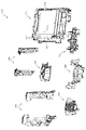
図3に示すように、パチンコ機10の背面側には、制御基板ユニット90,91と、裏パックユニット94とが主に備えられている。制御基板ユニット90は、主基板(主制御装置110)と音声ランプ制御基板(音声ランプ制御装置113)と表示制御基板(表示制御装置114)とが搭載されてユニット化されている。制御基板ユニット91は、払出制御基板(払出制御装置111)と発射制御基板(発射制御装置112)と電源基板(電源装置115)とカードユニット接続基板116とが搭載されてユニット化されている。   As shown in FIG. 3, control board units 90 and 91 and a back pack unit 94 are mainly provided on the back side of the pachinko machine 10. The control board unit 90 is unitized by mounting a main board (main control apparatus 110), an audio lamp control board (audio lamp control apparatus 113), and a display control board (display control apparatus 114). The control board unit 91 is unitized by mounting a payout control board (payout control apparatus 111), a firing control board (launching control apparatus 112), a power supply board (power supply apparatus 115), and a card unit connection board 116.

裏パックユニット94は、保護カバー部を形成する裏パック92と払出ユニット93とがユニット化されている。また、各制御基板には、各制御を司る1チップマイコンとしてのMPU、各種機器との連絡をとるポート、各種抽選の際に用いられる乱数発生器、時間計数や同期を図る場合などに使用されるクロックパルス発生回路等が、必要に応じて搭載されている。   The back pack unit 94 includes a back pack 92 and a dispensing unit 93 that form a protective cover. In addition, each control board is used for MPU as a one-chip microcomputer that controls each control, a port for communicating with various devices, a random number generator used for various lotteries, time counting and synchronization. A clock pulse generation circuit or the like is mounted as necessary.

なお、主制御装置110、音声ランプ制御装置113及び表示制御装置114、払出制御装置111及び発射制御装置112、電源装置115、カードユニット接続基板116は、それぞれ基板ボックス100〜104に収納されている。基板ボックス100〜104は、ボックスベースと該ボックスベースの開口部を覆うボックスカバーとを備えており、そのボックスベースとボックスカバーとが互いに連結されて、各制御装置や各基板が収納される。   The main control device 110, the sound lamp control device 113 and the display control device 114, the payout control device 111 and the firing control device 112, the power supply device 115, and the card unit connection board 116 are housed in the board boxes 100 to 104, respectively. . The board boxes 100 to 104 include a box base and a box cover that covers the opening of the box base. The box base and the box cover are connected to each other, and each control device and each board are accommodated.

また、基板ボックス100(主制御装置110)及び基板ボックス102(払出制御装置111及び発射制御装置112)は、ボックスベースとボックスカバーとを封印ユニット(図示せず)によって開封不能に連結(かしめ構造による連結)している。また、ボックスベースとボックスカバーとの連結部には、ボックスベースとボックスカバーとに亘って封印シール(図示せず)が貼着されている。この封印シールは、脆性な素材で構成されており、基板ボックス100,102を開封するために封印シールを剥がそうとしたり、基板ボックス100,102を無理に開封しようとすると、ボックスベース側とボックスカバー側とに切断される。よって、封印ユニット又は封印シールを確認することで、基板ボックス100,102が開封されたかどうかを知ることができる。   Further, the substrate box 100 (main control device 110) and the substrate box 102 (dispensing control device 111 and launch control device 112) connect the box base and the box cover so that they cannot be opened by a sealing unit (not shown) (caulking structure). Consolidated). In addition, a seal (not shown) is attached to the connecting portion between the box base and the box cover so as to cover the box base and the box cover. This seal seal is made of a brittle material. If the seal is to be peeled off in order to open the substrate boxes 100, 102, or if the substrate boxes 100, 102 are forcibly opened, the box base side and the box cover are removed. Cut to the side. Therefore, it is possible to know whether or not the substrate boxes 100 and 102 have been opened by checking the sealing unit or the sealing seal.

払出ユニット93は、裏パックユニット94の最上部に位置して上方に開口したタンク130と、タンク130の下方に連結され下流側に向けて緩やかに傾斜するタンクレール131と、タンクレール131の下流側に縦向きに連結されるケースレール132と、ケースレール132の最下流部に設けられ、払出モータ216(図4参照)の所定の電気的構成により球の払出を行う払出装置133とを備えている。タンク130には、遊技ホールの島設備から供給される球が逐次補給され、払出装置133により必要個数の球の払い出しが適宜行われる。タンクレール131には、当該タンクレール131に振動を付加するためのバイブレータ134が取り付けられている。   The payout unit 93 includes a tank 130 that is located at the top of the back pack unit 94 and opens upward, a tank rail 131 that is connected to the lower side of the tank 130 and is gently inclined toward the downstream side, and downstream of the tank rail 131. A case rail 132 that is vertically connected to the side, and a payout device 133 that is provided at the most downstream portion of the case rail 132 and that pays out a ball by a predetermined electrical configuration of the payout motor 216 (see FIG. 4). ing. The tank 130 is successively replenished with balls supplied from the island equipment of the game hall, and a required number of balls are paid out by the payout device 133 as appropriate. A vibrator 134 for applying vibration to the tank rail 131 is attached to the tank rail 131.

また、払出制御装置111には状態復帰スイッチ120が設けられ、発射制御装置112には可変抵抗器の操作つまみ121が設けられ、電源装置115にはRAM消去スイッチ122が設けられている。状態復帰スイッチ120は、例えば、払出モータ216(図4参照)部の球詰まり等、払出エラーの発生時に球詰まりを解消(正常状態への復帰)するために操作される。操作つまみ121は、発射ソレノイドの発射力を調整するために操作される。RAM消去スイッチ122は、パチンコ機10を初期状態に戻したい場合に電源投入時に操作される。   The payout control device 111 is provided with a state return switch 120, the firing control device 112 is provided with a variable resistor operation knob 121, and the power supply device 115 is provided with a RAM erase switch 122. The state return switch 120 is operated, for example, to eliminate ball clogging (return to a normal state) when a payout error occurs, such as ball clogging in the payout motor 216 (see FIG. 4). The operation knob 121 is operated to adjust the firing force of the firing solenoid. The RAM erase switch 122 is operated when the power is turned on to return the pachinko machine 10 to the initial state.

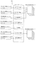
次に、図4を参照して、本パチンコ機10の電気的構成について説明する。図4は、パチンコ機10の電気的構成を示すブロック図である。   Next, the electrical configuration of the pachinko machine 10 will be described with reference to FIG. FIG. 4 is a block diagram showing an electrical configuration of the pachinko machine 10.

主制御装置110には、演算装置である1チップマイコンとしてのMPU201が搭載されている。MPU201には、該MPU201により実行される各種の制御プログラムや固定値データを記憶したROM202と、そのROM202内に記憶される制御プログラムの実行に際して各種のデータ等を一時的に記憶するためのメモリであるRAM203と、そのほか、割込回路やタイマ回路、データ送受信回路などの各種回路が内蔵されている。主制御装置110では、MPU201によって、大当たり抽選や第1図柄表示装置37A,37B及び第3図柄表示装置81における表示の設定、第2図柄表示装置における表示結果の抽選といったパチンコ機10の主要な処理を実行する。   The main controller 110 is equipped with an MPU 201 as a one-chip microcomputer that is an arithmetic unit. The MPU 201 includes a ROM 202 that stores various control programs executed by the MPU 201 and fixed value data, and a memory that temporarily stores various data when the control program stored in the ROM 202 is executed. A certain RAM 203 and various other circuits such as an interrupt circuit, a timer circuit, and a data transmission / reception circuit are incorporated. In the main control device 110, the main processing of the pachinko machine 10 such as jackpot lottery, display setting in the first symbol display devices 37A and 37B and the third symbol display device 81, and lottery of display results in the second symbol display device are performed by the MPU 201. Execute.

なお、払出制御装置111や音声ランプ制御装置113などのサブ制御装置に対して動作を指示するために、主制御装置110から該サブ制御装置へ各種のコマンドがデータ送受信回路によって送信されるが、かかるコマンドは、主制御装置110からサブ制御装置へ一方向にのみ送信される。   Various commands are transmitted from the main control device 110 to the sub control device by the data transmission / reception circuit in order to instruct the sub control device such as the payout control device 111 and the sound lamp control device 113 to operate. Such a command is transmitted from the main controller 110 to the sub controller only in one direction.

RAM203は、各種エリア、カウンタ、フラグのほか、MPU201の内部レジスタの内容やMPU201により実行される制御プログラムの戻り先番地などが記憶されるスタックエリアと、各種のフラグおよびカウンタ、I/O等の値が記憶される作業エリア(作業領域)とを有している。なお、RAM203は、パチンコ機10の電源の遮断後においても電源装置115からバックアップ電圧が供給されてデータを保持(バックアップ)できる構成となっており、RAM203に記憶されるデータは、すべてバックアップされる。   The RAM 203 stores various areas, counters, flags, a stack area for storing the contents of the internal registers of the MPU 201 and a return address of a control program executed by the MPU 201, various flags, counters, I / O, and the like. And a work area (work area) in which values are stored. Note that the RAM 203 is configured so that the backup voltage is supplied from the power supply device 115 and the data can be retained (backed up) even after the power of the pachinko machine 10 is shut off, and all data stored in the RAM 203 is backed up. .

停電などの発生により電源が遮断されると、その電源遮断時(停電発生時を含む。以下同様)のスタックポインタや、各レジスタの値がRAM203に記憶される。一方、電源投入時(停電解消による電源投入を含む。以下同様)には、RAM203に記憶される情報に基づいて、パチンコ機10の状態が電源遮断前の状態に復帰される。RAM203への書き込みはメイン処理(図示せず)によって電源遮断時に実行され、RAM203に書き込まれた各値の復帰は電源投入時の立ち上げ処理(図示せず)において実行される。なお、MPU201のNMI端子(ノンマスカブル割込端子)には、停電等の発生による電源遮断時に、停電監視回路252からの停電信号SG1が入力されるように構成されており、その停電信号SG1がMPU201へ入力されると、停電時処理としてのNMI割込処理(図示せず)が即座に実行される。   When the power is shut down due to the occurrence of a power failure or the like, the stack pointer and the value of each register when the power is shut off (including when the power failure occurs, the same applies hereinafter) are stored in the RAM 203. On the other hand, at the time of power-on (including power-on due to power failure cancellation, the same applies hereinafter), the state of the pachinko machine 10 is restored to the state before power-off based on information stored in the RAM 203. Writing to the RAM 203 is executed when the power is shut off by a main process (not shown), and restoration of each value written to the RAM 203 is executed in a start-up process (not shown) when the power is turned on. Note that the power failure signal SG1 from the power failure monitoring circuit 252 is input to the NMI terminal (non-maskable interrupt terminal) of the MPU 201 when the power is interrupted due to the occurrence of a power failure or the like. Is input immediately, an NMI interrupt process (not shown) as a power failure process is immediately executed.

主制御装置110のMPU201には、アドレスバス及びデータバスで構成されるバスライン204を介して入出力ポート205が接続されている。入出力ポート205には、払出制御装置111、音声ランプ制御装置113、第1図柄表示装置37A,37B、第2図柄表示装置、第2図柄保留ランプ、特定入賞口65aの開閉板の下辺を軸として前方側に開閉駆動するための大開放口ソレノイドや電動役物を駆動するためのソレノイドなどからなるソレノイド209が接続され、MPU201は、入出力ポート205を介してこれらに対し各種コマンドや制御信号を送信する。   An input / output port 205 is connected to the MPU 201 of the main control device 110 via a bus line 204 composed of an address bus and a data bus. The input / output port 205 has a payout control device 111, an audio lamp control device 113, first symbol display devices 37A and 37B, a second symbol display device, a second symbol holding lamp, and a lower side of the opening / closing plate of the specific winning opening 65a. A solenoid 209 made up of a large opening solenoid for opening and closing the front side and a solenoid for driving an electric accessory is connected to the MPU 201 via the input / output port 205. Send.

また、入出力ポート205には、図示しないスイッチ群およびスライド位置検出センサSや回転位置検出センサRを含むセンサ群などからなる各種スイッチ208、電源装置115に設けられた後述のRAM消去スイッチ回路253が接続され、MPU201は各種スイッチ208から出力される信号や、RAM消去スイッチ回路253より出力されるRAM消去信号SG2に基づいて各種処理を実行する。   The input / output port 205 includes a switch group (not shown), various switches 208 including a sensor group including a slide position detection sensor S and a rotation position detection sensor R, and a RAM erase switch circuit 253 described later provided in the power supply device 115. Are connected, and the MPU 201 executes various processes based on signals output from the various switches 208 and the RAM erase signal SG2 output from the RAM erase switch circuit 253.

払出制御装置111は、払出モータ216を駆動させて賞球や貸出球の払出制御を行うものである。演算装置であるMPU211は、そのMPU211により実行される制御プログラムや固定値データ等を記憶したROM212と、ワークメモリ等として使用されるRAM213とを有している。   The payout control device 111 drives the payout motor 216 to perform payout control of prize balls and rental balls. The MPU 211, which is an arithmetic unit, includes a ROM 212 that stores a control program executed by the MPU 211, fixed value data, and the like, and a RAM 213 that is used as a work memory or the like.

払出制御装置111のRAM213は、主制御装置110のRAM203と同様に、MPU211の内部レジスタの内容やMPU211により実行される制御プログラムの戻り先番地などが記憶されるスタックエリアと、各種のフラグおよびカウンタ、I/O等の値が記憶される作業エリア(作業領域)とを有している。RAM213は、パチンコ機10の電源の遮断後においても電源装置115からバックアップ電圧が供給されてデータを保持(バックアップ)できる構成となっており、RAM213に記憶されるデータは、すべてバックアップされる。なお、主制御装置110のMPU201と同様、MPU211のNMI端子にも、停電等の発生による電源遮断時に停電監視回路252から停電信号SG1が入力されるように構成されており、その停電信号SG1がMPU211へ入力されると、停電時処理としてのNMI割込処理(図示せず)が即座に実行される。   The RAM 213 of the payout control device 111, like the RAM 203 of the main control device 110, has a stack area for storing the contents of the internal registers of the MPU 211, the return address of the control program executed by the MPU 211, and various flags and counters. And a work area (work area) in which values such as I / O are stored. The RAM 213 is configured to be able to retain (backup) data by being supplied with a backup voltage from the power supply device 115 even after the power of the pachinko machine 10 is cut off, and all data stored in the RAM 213 is backed up. As with the MPU 201 of the main controller 110, the power failure signal SG1 is also input to the NMI terminal of the MPU 211 from the power failure monitoring circuit 252 when the power is interrupted due to the occurrence of a power failure or the like. When input to the MPU 211, an NMI interrupt process (not shown) as a power failure process is immediately executed.

払出制御装置111のMPU211には、アドレスバス及びデータバスで構成されるバスライン214を介して入出力ポート215が接続されている。入出力ポート215には、主制御装置110や払出モータ216、発射制御装置112などがそれぞれ接続されている。また、図示はしないが、払出制御装置111には、払い出された賞球を検出するための賞球検出スイッチが接続されている。なお、該賞球検出スイッチは、払出制御装置111に接続されるが、主制御装置110には接続されていない。   An input / output port 215 is connected to the MPU 211 of the payout control device 111 via a bus line 214 composed of an address bus and a data bus. The main control device 110, the payout motor 216, the firing control device 112, and the like are connected to the input / output port 215, respectively. Although not shown, the payout control device 111 is connected to a prize ball detection switch for detecting a prize ball that has been paid out. The prize ball detection switch is connected to the payout control device 111 but is not connected to the main control device 110.

発射制御装置112は、主制御装置110により球の発射の指示がなされた場合に、操作ハンドル51の回動操作量に応じた球の打ち出し強さとなるよう球発射ユニット112aを制御するものである。球発射ユニット112aは、図示しない発射ソレノイドおよび電磁石を備えており、その発射ソレノイドおよび電磁石は、所定条件が整っている場合に駆動が許可される。具体的には、遊技者が操作ハンドル51に触れていることをタッチセンサ51aにより検出し、球の発射を停止させるための発射停止スイッチ51bがオフ(操作されていないこと)を条件に、操作ハンドル51の回動操作量(回動位置)に対応して発射ソレノイドが励磁され、操作ハンドル51の操作量に応じた強さで球が発射される。   The launch control device 112 controls the ball launch unit 112a so that the launch strength of the ball according to the rotation operation amount of the operation handle 51 is obtained when the main control device 110 gives an instruction to launch a ball. . The ball launching unit 112a includes a launching solenoid and an electromagnet (not shown), and the firing solenoid and the electromagnet are permitted to be driven when predetermined conditions are met. Specifically, the touch sensor 51a detects that the player is touching the operation handle 51, and the operation is performed on the condition that the launch stop switch 51b for stopping the launch of the ball is off (not operated). The firing solenoid is excited corresponding to the amount of rotation (rotation position) of the handle 51, and a ball is launched with a strength corresponding to the amount of operation of the operation handle 51.

音声ランプ制御装置113は、音声出力装置(図示しないスピーカなど)226における音声の出力、ランプ表示装置(電飾部29〜33、表示ランプ34など)227における点灯および消灯の出力、変動演出(変動表示)や予告演出といった表示制御装置114で行われる第3図柄表示装置81の表示態様の設定などを制御するものである。演算装置であるMPU221は、そのMPU221により実行される制御プログラムや固定値データ等を記憶したROM222と、ワークメモリ等として使用されるRAM223とを有している。   The audio lamp control device 113 outputs audio in an audio output device (such as a speaker (not shown)) 226, outputs lighting and extinguishing in a lamp display device (such as the illumination units 29 to 33 and the display lamp 34), and fluctuating effects (variation). The display mode setting of the third symbol display device 81 performed by the display control device 114, such as display) and a notice effect, is controlled. The MPU 221 that is an arithmetic unit includes a ROM 222 that stores a control program executed by the MPU 221, fixed value data, and the like, and a RAM 223 that is used as a work memory or the like.

音声ランプ制御装置113のMPU221には、アドレスバス及びデータバスで構成されるバスライン224を介して入出力ポート225が接続されている。入出力ポート225には、主制御装置110、表示制御装置114、音声出力装置226、ランプ表示装置227、その他装置228、枠ボタン22、RTC(リアルタイムクロック)264などがそれぞれ接続されている。その他装置228には、駆動モータ340,430,522,640,740,830が含まれる。   An input / output port 225 is connected to the MPU 221 of the sound lamp control device 113 via a bus line 224 including an address bus and a data bus. The main control device 110, display control device 114, audio output device 226, lamp display device 227, other device 228, frame button 22, RTC (real time clock) 264, etc. are connected to the input / output port 225, respectively. Other devices 228 include drive motors 340, 430, 522, 640, 740, 830.

音声ランプ制御装置113は、主制御装置110から受信した各種のコマンド(変動パターンコマンド、停止種別コマンド等)に基づいて、第3図柄表示装置81の表示態様を決定し、決定した表示態様をコマンド(表示用変動パターンコマンド、表示用停止種別コマンド等)によって表示制御装置114へ通知する。また、音声ランプ制御装置113は、枠ボタン22からの入力を監視し、遊技者によって枠ボタン22が操作された場合は、第3図柄表示装置81で表示されるステージを変更したり、スーパーリーチ時の演出内容を変更したりするように、表示制御装置114へ指示する。ステージが変更される場合は、変更後のステージに応じた背面画像を第3図柄表示装置81に表示させるべく、変更後のステージに関する情報を含めた背面画像変更コマンドを表示制御装置114へ送信する。ここで、背面画像とは、第3図柄表示装置81に表示させる主要な画像である第3図柄の背面側に表示される画像のことである。表示制御装置114は、この音声ランプ制御装置113から送信されるコマンドに従って、第3図柄表示装置81に各種の画像を表示する。   The sound lamp control device 113 determines the display mode of the third symbol display device 81 based on various commands (variation pattern command, stop type command, etc.) received from the main control device 110, and uses the determined display mode as a command. The display control device 114 is notified by (display variation pattern command, display stop type command, etc.). The sound lamp control device 113 monitors the input from the frame button 22, and when the player operates the frame button 22, the stage displayed on the third symbol display device 81 is changed, or the super reach is performed. The display control device 114 is instructed to change the production contents at the time. When the stage is changed, a rear image change command including information about the changed stage is transmitted to the display control device 114 so that the rear image corresponding to the changed stage is displayed on the third symbol display device 81. . Here, the back image is an image displayed on the back side of the third symbol, which is a main image displayed on the third symbol display device 81. The display control device 114 displays various images on the third symbol display device 81 according to the command transmitted from the sound lamp control device 113.

また、音声ランプ制御装置113は、表示制御装置114から第3図柄表示装置81の表示内容を表すコマンド(表示コマンド)を受信する。音声ランプ制御装置113では、表示制御装置114から受信した表示コマンドに基づき、第3図柄表示装置81の表示内容に合わせて、その表示内容に対応する音声を音声出力装置226から出力し、また、その表示内容に対応させてランプ表示装置227の点灯および消灯を制御する。   Further, the sound lamp control device 113 receives a command (display command) representing the display content of the third symbol display device 81 from the display control device 114. The voice lamp control device 113 outputs the voice corresponding to the display content from the voice output device 226 in accordance with the display content of the third symbol display device 81 based on the display command received from the display control device 114, The lighting and extinguishing of the lamp display device 227 are controlled in accordance with the display contents.

表示制御装置114は、音声ランプ制御装置113及び第3図柄表示装置81が接続され、音声ランプ制御装置113より受信したコマンドに基づいて、第3図柄表示装置81における第3図柄の変動演出などの表示を制御するものである。また、表示制御装置114は、第3図柄表示装置81の表示内容を通知する表示コマンドを適宜音声ランプ制御装置113へ送信する。音声ランプ制御装置113は、この表示コマンドによって示される表示内容にあわせて音声出力装置226から音声を出力することで、第3図柄表示装置81の表示と音声出力装置226からの音声出力とをあわせることができる。   The display control device 114 is connected to the sound lamp control device 113 and the third symbol display device 81, and based on the command received from the sound lamp control device 113, the third symbol display device 81 has a variation effect of the third symbol, etc. The display is controlled. Further, the display control device 114 appropriately transmits a display command for notifying the display content of the third symbol display device 81 to the sound lamp control device 113. The voice lamp control device 113 outputs the voice from the voice output device 226 in accordance with the display content indicated by the display command, thereby matching the display of the third symbol display device 81 with the voice output from the voice output device 226. be able to.

電源装置115は、パチンコ機10の各部に電源を供給するための電源部251と、停電等による電源遮断を監視する停電監視回路252と、RAM消去スイッチ122(図3参照)が設けられたRAM消去スイッチ回路253とを有している。電源部251は、図示しない電源経路を通じて、各制御装置110〜114等に対して各々に必要な動作電圧を供給する装置である。その概要としては、電源部251は、外部より供給される交流24ボルトの電圧を取り込み、各種スイッチ208などの各種スイッチや、ソレノイド209などのソレノイド、モータ等を駆動するための12ボルトの電圧、ロジック用の5ボルトの電圧、RAMバックアップ用のバックアップ電圧などを生成し、これら12ボルトの電圧、5ボルトの電圧及びバックアップ電圧を各制御装置110〜114等に対して必要な電圧を供給する。   The power supply device 115 includes a power supply unit 251 for supplying power to each unit of the pachinko machine 10, a power failure monitoring circuit 252 for monitoring power interruption due to a power failure, and a RAM deletion switch 122 (see FIG. 3). And an erasing switch circuit 253. The power supply unit 251 is a device that supplies a necessary operating voltage to each of the control devices 110 to 114 through a power supply path (not shown). As its outline, the power supply unit 251 takes in the voltage of AC 24 volts supplied from the outside, and drives various switches such as various switches 208, solenoids such as the solenoid 209, motors, etc. A 5 volt voltage for logic, a backup voltage for RAM backup, and the like are generated, and the 12 volt voltage, the 5 volt voltage, and the backup voltage are supplied to the control devices 110 to 114 as necessary voltages.

停電監視回路252は、停電等の発生による電源遮断時に、主制御装置110のMPU201及び払出制御装置111のMPU211の各NMI端子へ停電信号SG1を出力するための回路である。停電監視回路252は、電源部251から出力される最大電圧である直流安定24ボルトの電圧を監視し、この電圧が22ボルト未満になった場合に停電(電源断、電源遮断)の発生と判断して、停電信号SG1を主制御装置110及び払出制御装置111へ出力する。停電信号SG1の出力によって、主制御装置110及び払出制御装置111は、停電の発生を認識し、NMI割込処理を実行する。なお、電源部251は、直流安定24ボルトの電圧が22ボルト未満になった後においても、NMI割込処理の実行に充分な時間の間、制御系の駆動電圧である5ボルトの電圧の出力を正常値に維持するように構成されている。よって、主制御装置110及び払出制御装置111は、NMI割込処理(図示せず)を正常に実行し完了することができる。   The power failure monitoring circuit 252 is a circuit for outputting a power failure signal SG1 to each NMI terminal of the MPU 201 of the main control device 110 and the MPU 211 of the payout control device 111 when the power is cut off due to the occurrence of a power failure or the like. The power failure monitoring circuit 252 monitors the DC stable voltage of 24 volts, which is the maximum voltage output from the power supply unit 251, and determines that a power failure (power interruption, power interruption) occurs when this voltage falls below 22 volts. Then, the power failure signal SG1 is output to the main controller 110 and the payout controller 111. Based on the output of the power failure signal SG1, the main controller 110 and the payout controller 111 recognize the occurrence of the power failure and execute the NMI interrupt process. Note that the power supply unit 251 outputs a voltage of 5 volts, which is a drive voltage of the control system, for a time sufficient to execute the NMI interrupt processing even after the DC stable voltage of 24 volts becomes less than 22 volts. Is maintained at a normal value. Therefore, main controller 110 and payout controller 111 can normally execute and complete the NMI interrupt process (not shown).

RAM消去スイッチ回路253は、RAM消去スイッチ122(図3参照)が押下された場合に、主制御装置110へ、バックアップデータをクリアさせるためのRAM消去信号SG2を出力するための回路である。主制御装置110は、パチンコ機10の電源投入時に、RAM消去信号SG2を入力した場合に、バックアップデータをクリアすると共に、払出制御装置111においてバックアップデータをクリアさせるための払出初期化コマンドを払出制御装置111に対して送信する。   The RAM erase switch circuit 253 is a circuit for outputting a RAM erase signal SG2 for clearing backup data to the main controller 110 when the RAM erase switch 122 (see FIG. 3) is pressed. When the RAM erase signal SG2 is input when the pachinko machine 10 is turned on, the main control device 110 clears the backup data, and the payout control device 111 issues a payout initialization command for clearing the backup data. Transmit to device 111.

なお、主制御装置110および音声ランプ制御装置113、表示制御装置114の構成の詳細については、図66〜図78を参照して後述する。   Details of the configuration of the main control device 110, the sound lamp control device 113, and the display control device 114 will be described later with reference to FIGS.

次いで、図5を参照して、遊技盤13における入賞口63,64,65a,640,650aやアウト口71,72などの各構成のレイアウト(配置)について説明する。図5は、遊技盤13の正面模式図である。なお、図5では、入賞口63,64,65a,640,650aなどの各構成が模式的に図示されると共に、遊技盤13の一部が部分的に拡大して図示される。   Next, with reference to FIG. 5, the layout (arrangement) of each component such as the winning ports 63, 64, 65 a, 640, 650 a and the out ports 71, 72 in the game board 13 will be described. FIG. 5 is a schematic front view of the game board 13. In addition, in FIG. 5, while each structure, such as winning opening 63, 64, 65a, 640, 650a, is illustrated typically, a part of game board 13 is partially expanded and illustrated.

図5に示すように、内レール61は、遊技領域の正面視において、右下側に配置される部分(第1アウト口71よりも右側の部分)が、直線状に延設されると共に第1アウト口71から離間される方向へ向けて上昇傾斜して形成される。   As shown in FIG. 5, the inner rail 61 has a portion disposed on the lower right side (a portion on the right side of the first out port 71) in a front view of the game area and extends linearly. It is formed to be inclined upward in the direction away from the 1-out port 71.

内レール61の右下側の先端部と外レール62の右上側の先端部との間には、それら両レール61,62と共に遊技領域の外縁を画定する樹脂製の外縁部材73が配設される。外縁部材73は、外レール62を延長した円弧状の壁面を内面側に設けて形成される円弧壁部73aと、その円弧壁部73aの下方に連設され鉛直方向(図5上下方向)に沿って直線状に延設される壁面を内面側に設けて形成される垂直壁部73bと、その垂直壁部73bの下方に連設され内レール61へ向けて下降傾斜しつつ直線状に延設される壁面を内面側に設けて形成される傾斜壁部73cとからなる。   Between the lower right end of the inner rail 61 and the upper right end of the outer rail 62, a resin outer edge member 73 that defines the outer edge of the game area together with the two rails 61 and 62 is disposed. The The outer edge member 73 has an arcuate wall 73a formed by providing an arcuate wall surface extending from the outer rail 62 on the inner surface side, and is continuously provided below the arcuate wall 73a in the vertical direction (vertical direction in FIG. 5). A vertical wall portion 73b formed by providing a wall surface extending linearly along the inner surface side, and extending linearly while being inclined downward toward the inner rail 61 and continuously provided below the vertical wall portion 73b. It consists of the inclined wall part 73c formed by providing the wall surface provided in an inner surface side.

このように、内レール61、外レール62及び外縁部材73により画定される遊技領域は、略円形状の一部(図5下方右側部分)が、略矩形状に形成され外方へ拡大された形状とされる。詳細には、第1アウト口71よりも右側に配設される内レール61の直線状の部分と、外縁部材73の傾斜壁部73c及び垂直壁部73bとにより画定される領域が略矩形状に形成される。   In this way, the game area defined by the inner rail 61, the outer rail 62, and the outer edge member 73 has a substantially circular part (lower right part in FIG. 5) formed in a substantially rectangular shape and expanded outward. Shaped. Specifically, a region defined by the linear portion of the inner rail 61 disposed on the right side of the first out port 71 and the inclined wall portion 73c and the vertical wall portion 73b of the outer edge member 73 is substantially rectangular. Formed.

これにより、遊技領域が内レール61及び外レール62を延長した略円形状に形成される場合と比較して、略矩形状の領域(図5下方右側部分)を備える分、遊技領域全体としての面積を拡大することができる。よって、その拡大した領域を、一般入賞口63、第1入賞口64、第2入賞口640、第1可変入賞装置65、第2可変入賞装置650、スルーゲート67などを配設するスペースとして、或いは、球を流下させる経路を形成するためのスペースとして活用して、各入賞口63,64,65a,640,650aや球の流下経路などの配置の自由度を高めることができる。その結果、第3図柄表示装置81の下縁の位置を下方(図5下側)へ下げることができるので、その分、第3図柄表示装置81の大型化を図ることができる。   Thereby, compared with the case where the game area is formed in a substantially circular shape obtained by extending the inner rail 61 and the outer rail 62, the game area as a whole is provided by the provision of a substantially rectangular area (lower right portion in FIG. 5). The area can be enlarged. Therefore, the enlarged area is used as a space for arranging the general winning port 63, the first winning port 64, the second winning port 640, the first variable winning device 65, the second variable winning device 650, the through gate 67, and the like. Or it can utilize as a space for forming the path | route which flows down a ball | bowl, and the freedom degree of arrangement | positioning, such as each winning opening 63, 64, 65a, 640, 650a, the flow path | route of a ball | bowl, can be raised. As a result, the position of the lower edge of the third symbol display device 81 can be lowered (lower side in FIG. 5), so that the size of the third symbol display device 81 can be increased accordingly.

即ち、従来のパチンコ機では、第3図柄表示装置81の下方において、第1入賞口64、第2入賞口640及び可変入賞装置65が上下方向(図5上下方向)に沿って直列に配置されていた。そのため、第3図柄表示装置81の下方に必要なスペースが上下方向に嵩み、かかる第3図柄表示装置81の大型化が阻害されていた。   That is, in the conventional pachinko machine, the first winning port 64, the second winning port 640, and the variable winning device 65 are arranged in series along the vertical direction (the vertical direction in FIG. 5) below the third symbol display device 81. It was. For this reason, the necessary space below the third symbol display device 81 is increased in the vertical direction, and the increase in size of the third symbol display device 81 is hindered.

これに対し、本実施形態の遊技盤13によれば、遊技領域の拡大された部分(略矩形状の領域、図5下方右側部分)を入賞口などの配設スペースあるいは球の流下経路の形成スペースとして利用することができる。具体的には、本実施形態では、第2入賞口640および第1可変入賞装置65が第1入賞口64の直下ではなく、上述した遊技領域の拡大された部分に配置される。よって、その分、第1入賞口64の位置を下方へ下げることができるので、第3図柄表示装置81の大型化を図ることができる。   On the other hand, according to the gaming board 13 of the present embodiment, an enlarged portion of the gaming area (substantially rectangular area, the lower right portion in FIG. 5) is formed as an arrangement space such as a prize opening or a flow path of a ball. It can be used as a space. Specifically, in the present embodiment, the second winning opening 640 and the first variable winning device 65 are arranged not in the immediate vicinity of the first winning opening 64 but in the enlarged portion of the game area described above. Accordingly, since the position of the first winning port 64 can be lowered downward, the size of the third symbol display device 81 can be increased.

また、本実施形態の遊技機13によれば、第2特定入賞口650aも、第1入賞口64の直下ではなく、第1入賞口64に対して遊技領域の幅方向一側(可変入賞装置65と反対側、図5左側)にオフセットされ、かつ、内レール61(遊技領域の下縁)に当接する位置(即ち、第2特定入賞口650aと内レール61との間を球が通過不能となる位置)に配置される。よって、その分、第1入賞口64の位置を下方へ下げることができるので、第3図柄表示装置81の大型化を図ることができる。   Further, according to the gaming machine 13 of the present embodiment, the second specific prize opening 650a is not directly below the first prize opening 64, but on the one side in the width direction of the game area with respect to the first prize opening 64 (variable prize apparatus). The ball is not allowed to pass between the position that is offset to the opposite side of 65 (left side in FIG. 5) and abuts against the inner rail 61 (the lower edge of the game area) (that is, between the second specific prize opening 650a and the inner rail 61). Is located). Accordingly, since the position of the first winning port 64 can be lowered downward, the size of the third symbol display device 81 can be increased.

この場合、本実施形態の遊技盤13によれば、遊技領域から球排出路へ球を排出するための経路を2ヶ所(第1アウト口71及び第2アウト口72)に設けることで、第3図柄表示装置81の更なる大型化が可能とされている。   In this case, according to the gaming board 13 of the present embodiment, the path for discharging the ball from the gaming area to the ball discharge path is provided at two places (the first out port 71 and the second out port 72). Further enlargement of the three-symbol display device 81 is possible.

即ち、第3図柄表示装置81を大型化するためには、かかる第3図柄表示装置81の下縁の位置が下方に下がるため、その分、入賞口の位置も下方へ下げる必要がある。例えば、第1入賞口64の位置が下方へ下がると、案内板部材74(右打ち時の球(可変表示装置ユニット80の右方を通過した球)を第2特定入賞口650aへ案内する部材)の位置も、球を流下させるスペースを第1入賞口64との間に確保するべく、下方へ下げる必要が生じ、その結果、第2特定入賞口650aの位置も下方へ下げる必要が生じる。   That is, in order to increase the size of the 3rd symbol display device 81, the position of the lower edge of the 3rd symbol display device 81 is lowered downward, and accordingly, the position of the winning opening needs to be lowered. For example, when the position of the first winning port 64 is lowered, the guide plate member 74 (a member that guides the right-handed ball (the ball that has passed rightward of the variable display device unit 80) to the second specific winning port 650a. ) Also needs to be lowered in order to secure a space for the ball to flow down from the first winning port 64, and as a result, the position of the second specific winning port 650a also needs to be lowered.

しかしながら、第2特定入賞口650aの位置が下方へ下がり過ぎると、第2特定入賞口650aの下方(内レール61との間)に球を流下させるためのスペースを確保できなくなる。即ち、入賞口に入賞されずに流下した球を第1入賞口64の下方に配設されるアウト口から排出できなくなる。そのため、かかる第2特定入賞口650aの位置を下方へ下げるには限界があり、第3図柄表示装置81を十分に大型化することができない要因となる。   However, if the position of the second specific winning opening 650a is lowered too much, it is not possible to secure a space for flowing the ball below the second specific winning opening 650a (between the inner rail 61). In other words, the ball that has flowed down without winning the prize winning opening cannot be discharged from the out opening arranged below the first winning prize opening 64. For this reason, there is a limit to lowering the position of the second specific prize winning opening 650a downward, which becomes a factor that the third symbol display device 81 cannot be sufficiently enlarged.

これに対し、本実施形態の遊技盤13によれば、上述したように、第1アウト口71に加え、第2アウト口72が、第2特定入賞口650aを挟んで、第1アウト口71の反対側に配設されている(即ち、第2特定入賞口650aの右側および左側に第1アウト口71及び第2アウト口72がそれぞれ配設されている)ので、遊技領域を流下する球であって、第2特定入賞口650aよりも正面視右側(図5右側)において遊技領域の下端(内レール61又は外縁部材73)に達した球は、内レール61又は外縁部材73の傾斜に沿って流下させ、第1アウト口71により球排出路へ排出できる一方、第2特定入賞口650aよりも正面視左側において遊技領域の下端(内レール61)に達した球は、内レール61の傾斜(湾曲)に沿って流下させ、第2アウト口72から球排出路へ排出できる。   On the other hand, according to the game board 13 of the present embodiment, as described above, in addition to the first out port 71, the second out port 72 sandwiches the second specific winning port 650a and the first out port 71. (Ie, the first out port 71 and the second out port 72 are respectively disposed on the right side and the left side of the second specific winning port 650a), so that the ball flows down in the game area. The ball that has reached the lower end (inner rail 61 or outer edge member 73) of the game area on the right side (right side in FIG. 5) from the second specific winning opening 650a is inclined to the inner rail 61 or outer edge member 73. The ball that reaches the lower end (inner rail 61) of the game area on the left side of the front view from the second specific winning port 650a is allowed to flow down along the inner rail 61. Flow along a slope (curvature) Is allowed, it can be discharged from the second out-port 72 to the spherical discharge passage.

このように、遊技領域から球排出路へ球を排出するための経路を2ヶ所(第1アウト口71及び第2アウト口72)に設けることで、第2特定入賞口650aの下方(内レール61との間)に、球を流下させるためのスペースを確保することを不要とできる。よって、第2特定入賞口650aの位置を更に下方に下げる(内レール61に近接させる又は連設させる)ことができるので、その分、案内板部材75の位置を下方へ下げることができ、ひいては、第1入賞口64の位置を下方へ下げることができるので、その分、第3図柄表示装置81の更なる大型化を図ることができる。   Thus, by providing two paths (first out port 71 and second out port 72) for discharging the ball from the game area to the ball discharge path, the second specific winning port 650a (inner rail) 61), it is unnecessary to secure a space for the sphere to flow down. Therefore, since the position of the 2nd specific prize opening 650a can be lowered further (closer to the inner rail 61 or connected), the position of the guide plate member 75 can be lowered accordingly, and consequently Since the position of the first winning port 64 can be lowered, the size of the third symbol display device 81 can be further increased accordingly.

なお、本実施形態では、第2入賞口640および第1特定入賞口65aが盤面右側にオフセットされて配設されると共に、第2特定入賞口650aが盤面左側にオフセットされかつ内レール61に近接(又は当接)されて配設されることで、回転動作ユニット300による演出をより効果的に行うことができる。   In the present embodiment, the second prize winning port 640 and the first specific prize winning port 65a are arranged offset to the right side of the board surface, and the second specific prize winning port 650a is offset to the left side of the board surface and close to the inner rail 61. By being arranged (or abutting), it is possible to more effectively perform the effect by the rotary operation unit 300.

即ち、遊技者が右打ちを行う場合には、球が流下する盤面右側のみが遊技者により注目され、特に、第2入賞口640への入賞がなされなかった球に対しては、それ以降の流下が遊技者に注目されることは少ない。この場合、本実施形態では、可変表示装置ユニット80の右方を通過した球のうち、第2入賞口640の上側を右から左へ通過した球は、案内板部材74の上側を通過し、第2特定入賞口650aへ向けて流下される。そのため、第2入賞口640への入賞がなされなかった場合でも、次いで、第2特定入賞口650aへの入賞の機会が発生し、その第2特定入賞口650aへの入賞の期待から、第2入賞口640の上側を右から左へ通過した球を遊技者に注目させる(視線を向けさせる)ことができる。これにより、遊技者の視線を、可変表示装置ユニット80下方における盤面中央にも向けさせることができる。後述するように、本実施形態では、第1入賞口64の背面側に回転動作ユニット300が配設され、その回転動作ユニット300が遊技盤13越しに(遊技盤13を透過して)視認可能とされるので、第2入賞口640への入賞がなされなかった球が、第2特定入賞口650aへ向けて流下する際に、回転動作ユニット300による演出も遊技者に視認させ、かかる回転動作ユニット300の演出効果を高めることができる。   That is, when the player makes a right strike, only the right side of the board on which the ball flows down is noticed by the player, and in particular, for the ball that has not been awarded to the second prize opening 640, The downflow is rarely noticed by players. In this case, in the present embodiment, among the spheres that have passed to the right of the variable display device unit 80, the sphere that has passed from the right to the left above the second winning opening 640 has passed above the guide plate member 74, It flows down toward the second specific prize winning opening 650a. For this reason, even when the second prize opening 640 has not been won, an opportunity to win the second specific prize opening 650a is generated, and the second prize winning expectation to the second specific prize opening 650a is expected to be the second. It is possible to make the player pay attention to the sphere that has passed from the right to the left above the winning opening 640 (the line of sight is directed). Accordingly, the player's line of sight can be directed toward the center of the board surface below the variable display device unit 80. As will be described later, in the present embodiment, the rotary operation unit 300 is disposed on the back side of the first winning opening 64, and the rotary operation unit 300 is visible through the game board 13 (through the game board 13). Therefore, when a ball that has not been won at the second prize opening 640 flows down toward the second specific prize opening 650a, the player also visually recognizes the effect by the rotation operation unit 300, and the rotation operation is performed. The production effect of the unit 300 can be enhanced.

上述したように、遊技盤13は、ベース板60が光透過性の樹脂材料から形成され、そのベース板60の背面側に配設される回転動作ユニット300を正面側から遊技者に視認させることが可能とされる。ここで、回転動作ユニット300は、第1入賞口64への入賞を契機として又は入賞による抽選の結果を契機として動作される装置であり、遊技盤13(ベース板60)の背面側において、第1入賞口64に対応する位置に配設される。   As described above, in the game board 13, the base plate 60 is made of a light-transmitting resin material, and the player can visually recognize the rotary operation unit 300 disposed on the back side of the base plate 60 from the front side. Is possible. Here, the rotation operation unit 300 is a device that is operated in response to winning in the first winning opening 64 or in response to a result of a lottery by winning, and on the back side of the game board 13 (base plate 60), It is arranged at a position corresponding to one winning opening 64.

よって、第1入賞口64へ向けて流下する球を目で追う遊技者に対し、特に、第1入賞口64に球が入賞した場合には、その第1入賞口64の背後において、回転動作ユニット300による演出を視認させることができるので、第1入賞口64への球の入賞に伴う演出を効果的に行うことができる。なお、回転動作ユニット300の詳細構成については後述する。   Therefore, for the player who follows the ball flowing toward the first winning port 64, especially when the ball wins the first winning port 64, the rotation operation is performed behind the first winning port 64. Since the effect by the unit 300 can be visually recognized, the effect accompanying the winning of the ball to the first winning opening 64 can be effectively performed. The detailed configuration of the rotation operation unit 300 will be described later.

この場合、第1入賞口64に対し、第2入賞口640及び第1可変入賞装置65が左右方向(遊技領域の幅方向、図5右方向)にオフセットされて配置されているので、その分、第1入賞口64及び回転動作ユニット300の位置を下方(図5下側)へ下げることができ、その結果、回転動作ユニット300を第1入賞口64に対応する位置であって遊技盤13(ベース板60)の背面側に配設する場合であっても、第3図柄表示装置81の大型化を図ることができる。   In this case, since the second winning port 640 and the first variable winning device 65 are offset with respect to the first winning port 64 in the left-right direction (the width direction of the game area, the right direction in FIG. 5), The positions of the first winning port 64 and the rotary operation unit 300 can be lowered (lower side in FIG. 5), and as a result, the rotary operation unit 300 is located at a position corresponding to the first winning port 64 and the gaming board 13. Even when it is disposed on the back side of the (base plate 60), the size of the third symbol display device 81 can be increased.

即ち、従来のパチンコ機のように、第1入賞口64、第2入賞口640及び第1可変入賞装置65が上下方向に直列に配置される場合には、第1入賞口64に対応する位置において遊技盤13(ベース板60)の背面側に回転動作ユニット300を配設することは、かかる回転動作ユニット300と第2入賞口640及び第1可変入賞装置65とが干渉するため、第1入賞口64、第2入賞口640及び第1可変入賞装置65の配設に必要なスペースが上下方向に嵩み、第3図柄表示装置81の大型化を阻害することになる。   That is, when the first winning port 64, the second winning port 640, and the first variable winning device 65 are arranged in series in the vertical direction as in a conventional pachinko machine, the position corresponding to the first winning port 64 In this case, the rotation operation unit 300 is disposed on the back side of the game board 13 (base plate 60) because the rotation operation unit 300 interferes with the second winning port 640 and the first variable winning device 65. The space required for the arrangement of the winning port 64, the second winning port 640, and the first variable winning device 65 is increased in the vertical direction, which obstructs the increase in the size of the third symbol display device 81.

これに対し、本実施形態の遊技盤13によれば、上述したように、第1入賞口64に対し、第2入賞口640、第1可変入賞装置65及び第2可変入賞装置650が左右方向(遊技領域の幅方向)にオフセットして配置されているので、これら第2入賞口640、第1可変入賞装置65及び第2可変入賞装置650と回転動作ユニット300との干渉を回避でき、その分、第1入賞口64の位置を下方へ下げることができ、第3図柄表示装置81の大型化を図ることができる。   On the other hand, according to the game board 13 of the present embodiment, as described above, the second winning port 640, the first variable winning device 65, and the second variable winning device 650 are in the horizontal direction with respect to the first winning port 64. Since it is arranged offset (in the width direction of the game area), the interference between the second winning port 640, the first variable winning device 65, the second variable winning device 650 and the rotary operation unit 300 can be avoided. Thus, the position of the first winning port 64 can be lowered downward, and the size of the third symbol display device 81 can be increased.

特に、第1可変入賞装置65については、遊技領域の下方右側の略矩形状に拡大された領域を利用して右側にオフセットされることで、そのオフセット量を十分に確保できると共に、第2可変入賞装置650については、第1アウト口71に加えて第2アウト口72が設けられることで、球が流下するための下方のスペースの確保を考慮せずに、その位置を下方へ下げることができる。これにより、回転動作ユニット300を配設するためのスペースをより広く確保できるので、第3図柄表示装置81の大型化と回転動作ユニット300の大型化という背反する課題を解決することができる。その結果、第3図柄表示装置81による演出効果と回転動作ユニット300による演出効果との両者の演出効果を高めることができる。   In particular, the first variable winning device 65 is offset to the right side by using a substantially rectangular area on the lower right side of the game area, so that the offset amount can be sufficiently secured and the second variable With respect to the winning device 650, the second out port 72 is provided in addition to the first out port 71, so that the position can be lowered downward without taking into account the space below for the ball to flow down. it can. Thereby, since the space for arrange | positioning the rotation operation unit 300 can be ensured more widely, the contradictory subject of the enlargement of the 3rd symbol display apparatus 81 and the enlargement of the rotation operation unit 300 can be solved. As a result, the effect of both the effect by the third symbol display device 81 and the effect by the rotary operation unit 300 can be enhanced.

ここで、回転動作ユニット300は、第1入賞口64を中心として回転可能な略円形状に形成される。これにより、第1入賞口64を取り囲む周囲全体を演出のための領域とすることができる。即ち、回転動作ユニット300による演出をその第1入賞口64の背面側において遊技者に視認させることできる。よって、第1入賞口64への入賞を契機として演出が開始される場合には、球が入球した第1入賞口64を中心とする領域で演出が行われることにより、第1入賞口64への入賞に伴う演出の演出効果を高めることができる。   Here, the rotation operation unit 300 is formed in a substantially circular shape that can rotate around the first winning port 64. Thereby, the whole circumference | surroundings surrounding the 1st winning opening 64 can be made into the area | region for production. That is, the player can visually recognize the effect by the rotary operation unit 300 on the back side of the first winning port 64. Therefore, in the case where the production starts with the winning of the first prize opening 64 as a trigger, the production is performed in an area centered on the first prize opening 64 where the ball has entered, whereby the first prize opening 64 is obtained. The production effect of the production accompanying winning a prize can be enhanced.

また、回転動作ユニット300の状態(例えば、回転位置や点灯状態)が所定の状態となったことを契機として、第1入賞口64へ球を入賞させることを遊技者が開始する場合には、遊技者が視認している対象物(所定の状態となった回転動作ユニット300)の中心へ向けて遊技球を入球させることとでき、回転動作ユニット300による演出の演出効果を高めることができる。   In addition, when the player starts to win a ball to the first winning opening 64 when the state (for example, the rotation position or the lighting state) of the rotation operation unit 300 becomes a predetermined state, A game ball can be made to enter the center of the object (the rotary motion unit 300 in a predetermined state) that is being visually recognized by the player, and the effect of staging by the rotary motion unit 300 can be enhanced. .

更に、このように、回転動作ユニット300が略円形状に形成されることで、かかる回転動作ユニット300の周囲のスペースを有効に活用でき、他の入賞口などのための配設スペースを効率的に確保できる。特に、第2可変入賞装置650の配設スペースを効率的に確保できる。即ち、第1可変入賞装置65については、遊技領域の下方右側の略矩形状に拡大された領域を利用して第1入賞口64に対して右側にオフセットできるため、その右側へのオフセット量を比較的確保しやすい一方、第2可変入賞装置650については、内レール61が円弧状に湾曲されているが故に、第1入賞口64に対する左側へのオフセット量を十分に確保することが困難となる。この場合、回転動作ユニット300が略円形状とされていることで、かかる回転動作ユニット300の下方左側において、第2可変入賞装置650を配設するためのスペースを内レール61との間に効率的に確保できる。   Furthermore, since the rotary operation unit 300 is formed in a substantially circular shape as described above, the space around the rotary operation unit 300 can be effectively used, and the arrangement space for other prize winning holes and the like can be efficiently used. Can be secured. In particular, the space for arranging the second variable winning device 650 can be efficiently secured. In other words, the first variable winning device 65 can be offset to the right side with respect to the first winning port 64 by using the area that is enlarged in a substantially rectangular shape on the lower right side of the game area. While it is relatively easy to secure, the second variable winning device 650 is difficult to secure a sufficient amount of offset to the left with respect to the first winning port 64 because the inner rail 61 is curved in an arc shape. Become. In this case, since the rotary operation unit 300 has a substantially circular shape, a space for disposing the second variable winning device 650 is efficiently provided between the inner rail 61 and the lower left side of the rotary operation unit 300. Can be secured.

また、回転動作ユニット300は、第1入賞口64を中心とする略円形状に形成されるので、かかる回転動作ユニット300を遊技領域の幅方向(図5左右方向)略中央に配置することができる。即ち、第3図柄表示装置81の下縁と内レール61との間の距離(図5上下方向の距離)が最大となる仮想線上に、回転動作ユニット300の中心を配置することができる。よって、第3図柄表示装置81の大型化を図りつつ、遊技領域の限られたスペースを有効に活用できるので、回転動作ユニット300を配設するためのスペースをより広く確保して、かかる回転動作ユニット300の大型化も効率的に行うことができる。   Further, since the rotational operation unit 300 is formed in a substantially circular shape centering on the first winning opening 64, the rotational operation unit 300 can be disposed at the approximate center in the width direction (the left-right direction in FIG. 5) of the game area. it can. That is, the center of the rotational operation unit 300 can be arranged on the imaginary line where the distance between the lower edge of the third symbol display device 81 and the inner rail 61 (the distance in the vertical direction in FIG. 5) is maximum. Therefore, the space of the game area can be effectively utilized while increasing the size of the third symbol display device 81, so that the space for disposing the rotation operation unit 300 can be secured more widely and the rotation operation can be performed. The unit 300 can be increased in size efficiently.

本実施形態では、上述したように、第2入賞口640が、第1入賞口64の直下ではなく、第1入賞口64に対して遊技領域の幅方向他側(第1可変入賞装置65側、図5右側)にオフセットされて配置される。この場合、第2入賞口640は、その開口641が遊技領域の幅方向他側(第1可変入賞装置65側、図5右側)を臨む姿勢で配設される。これにより、第2入賞口640への入賞のために球を流下させるスペースを、かかる第2入賞口640の上方に設けることを不要として、その分、第3図柄表示装置81の下縁の位置を下方に下げることができる。その結果、第3図柄表示装置81の大型化を図ることができる。   In the present embodiment, as described above, the second winning port 640 is not directly below the first winning port 64, but on the other side in the width direction of the game area with respect to the first winning port 64 (the first variable winning device 65 side). The right side of FIG. In this case, the second winning opening 640 is disposed in such a posture that the opening 641 faces the other side in the width direction of the gaming area (the first variable winning device 65 side, the right side in FIG. 5). Accordingly, it is not necessary to provide a space for allowing the ball to flow down to win the second winning port 640 above the second winning port 640, and accordingly, the position of the lower edge of the third symbol display device 81 correspondingly. Can be lowered downward. As a result, the size of the third symbol display device 81 can be increased.

また、本実施形態では、上述したように、第2特定入賞口650aが、第1入賞口64の直下ではなく、第1入賞口64に対して遊技領域の幅方向一側(第1可変入賞装置65と反対側、図5左側)にオフセットされて配置される。この場合、第2特定入賞口650aは、その開口651が遊技領域の幅方向他側(第1可変入賞装置65側、図5右側)を臨む姿勢で配設される。これにより、第2特定入賞口650aへの入賞のために球を流下させるスペースを、かかる第2特定入賞口650aの上方に設けることを不要として、その分、第3図柄表示装置81の下縁の位置を下方に下げることができる。その結果、第3図柄表示装置81の大型化を図ることができる。   In the present embodiment, as described above, the second specific prize opening 650a is not directly below the first prize opening 64, but on the one side in the width direction of the game area (the first variable prize) with respect to the first prize opening 64. Opposite to the device 65, the left side of FIG. In this case, the second specific winning opening 650a is arranged in such a posture that the opening 651 faces the other side in the width direction of the gaming area (the first variable winning device 65 side, the right side in FIG. 5). Accordingly, it is unnecessary to provide a space for the ball to flow down to win the second specific winning port 650a above the second specific winning port 650a, and accordingly, the lower edge of the third symbol display device 81. The position of can be lowered downward. As a result, the size of the third symbol display device 81 can be increased.

即ち、第2入賞口640の開口641及び第2特定入賞口650aの開口651が遊技領域の上方(図5上側)の臨む姿勢で配設される場合には、球を流下させるためのスペースを開口641,651の真上に確保する必要が生じ、その分、第3図柄表示装置81の下縁の位置を上方に上げる必要が生じ、第3図柄表示装置81の大型化が阻害される。これに対し、本実施形態のように、開口641,651が遊技領域の幅方向他側を臨む場合には、球を流下させるためのスペースを開口641,651の斜め上方(図5右上側)に確保すれば良く、その分、第3図柄表示装置81の下縁の位置を下方に下げることができる。その結果、第3図柄表示装置81の大型化を図ることができる。   That is, when the opening 641 of the second winning opening 640 and the opening 651 of the second specific winning opening 650a are arranged in a posture facing the upper side of the game area (upper side in FIG. 5), a space for allowing the ball to flow down is provided. It is necessary to ensure the position directly above the openings 641 and 651, and accordingly, it is necessary to raise the position of the lower edge of the third symbol display device 81, and the size of the third symbol display device 81 is hindered. On the other hand, when the openings 641 and 651 face the other side in the width direction of the game area as in this embodiment, a space for flowing down the ball is obliquely above the openings 641 and 651 (upper right side in FIG. 5). Therefore, the position of the lower edge of the third symbol display device 81 can be lowered downward. As a result, the size of the third symbol display device 81 can be increased.

このように、開口641,651が遊技領域の幅方向他側を臨む場合には、電動役物640a,650bを、第2入賞口640及び第2特定入賞口650aの真上ではなく、第2入賞口640及び第2特定入賞口650aの側方に配置することができる。即ち、電動役物640a,650bの配置スペースを第2入賞口640及び第2特定入賞口650aの真上に確保する必要がなく、その分、第3図柄表示装置81の下縁の位置を下方に下げることができる。その結果、第3図柄表示装置81の更なる大型化を図ることができる。   As described above, when the openings 641 and 651 face the other side in the width direction of the game area, the electric winnings 640a and 650b are not placed directly above the second prize winning opening 640 and the second specific winning prize opening 650a. It can arrange | position to the side of the winning opening 640 and the 2nd specific winning opening 650a. That is, it is not necessary to secure the space for arranging the electric winnings 640a and 650b directly above the second winning port 640 and the second specific winning port 650a, and accordingly, the position of the lower edge of the third symbol display device 81 is lowered. Can be lowered. As a result, the size of the third symbol display device 81 can be further increased.

更に、開口641,651が遊技領域の幅方向他側を臨むことで、その開口641,651の開放および閉鎖を行うための電動役物640a,650bを一対設けることを不要として、片側のみとすることができる。これにより、電動役物640a,650bを駆動するための駆動手段(例えば、ソレノイド)に必要とされる容量を小型化して、部品コストの削減を図ることができる。同時に、消費エネルギーの抑制を図ることができる。   Furthermore, since the openings 641 and 651 face the other side in the width direction of the game area, it is not necessary to provide a pair of electric accessories 640a and 650b for opening and closing the openings 641 and 651, and only one side is provided. be able to. As a result, the capacity required for the driving means (for example, solenoid) for driving the electric accessories 640a and 650b can be reduced, and the component cost can be reduced. At the same time, energy consumption can be suppressed.

また、開口641が遊技領域の幅方向他側を臨むことで、第2入賞口640への入賞の難易度が過度に低下することを防ぐことができる。即ち、本実施形態では、第3図柄表示装置81の下縁の位置を下方に下げるので、入賞口等の配設スペースが限定され、第2入賞口640と、スルーゲート67との配置位置の間隔が狭くなる。そのため、第1入賞口64、第2入賞口640及び第1可変入賞装置65が上下方向に直列に配置される従来のパチンコ機に比較して、第2入賞口640へ入球させる難易度が低下し、遊技性を損なう恐れがある。そこで、開口641を遊技領域の幅方向他側を臨むように形成することで、第2入賞口640の真上から球が入賞することを防止すると共に、電動役物640aが開状態にある場合にのみ第2入賞口640に入賞可能とさせることができる。これにより、第2入賞口640へ入賞させる難易度が低下することを防ぎ、遊技性を向上させることができる。   In addition, since the opening 641 faces the other side in the width direction of the game area, it is possible to prevent the difficulty of winning the prize to the second prize opening 640 from excessively decreasing. That is, in this embodiment, since the position of the lower edge of the 3rd symbol display device 81 is lowered, the arrangement space for the winning opening etc. is limited, and the arrangement positions of the second winning opening 640 and the through gate 67 are limited. The interval is narrowed. Therefore, compared with the conventional pachinko machine in which the first winning port 64, the second winning port 640, and the first variable winning device 65 are arranged in series in the vertical direction, the difficulty level of entering the second winning port 640 is more difficult. There is a risk of lowering the gameability. Therefore, when the opening 641 is formed so as to face the other side in the width direction of the game area, it is possible to prevent the ball from winning from directly above the second winning opening 640 and the electric accessory 640a is in the open state. It is possible to make it possible to win a prize at the second winning opening 640 only. As a result, it is possible to prevent the difficulty of winning a prize to the second prize opening 640 from decreasing, and to improve the game playability.

また、開口651が遊技領域の幅方向他側を臨むことで、第2特定入賞口650aの開口651から、第2特定入賞口650aまでの距離(図5左右方向寸法)を長くしても、第3図柄表示装置81と第2特定入賞口650aとの間の距離に影響を与えない。よって、第3図柄表示装置81の大型化を図りつつ、第2特定入賞口650aへの球の入賞を検出するセンサ装置652を開口651と第2特定入賞口650aとの間に配設することができる。これにより、第2特定入賞口650aへ球が入賞したことの検出速度を速めることができるので、入賞に伴う遊技者の高揚感を高めることができる。   In addition, since the opening 651 faces the other side in the width direction of the game area, even if the distance from the opening 651 of the second specific winning opening 650a to the second specific winning opening 650a (the horizontal dimension in FIG. 5) is increased, It does not affect the distance between the third symbol display device 81 and the second specific prize opening 650a. Therefore, while increasing the size of the third symbol display device 81, the sensor device 652 for detecting the winning of a ball to the second specific winning opening 650a is disposed between the opening 651 and the second specific winning opening 650a. Can do. Thereby, since the detection speed that the ball has won the second specific winning opening 650a can be increased, it is possible to enhance the player's feeling of exaltation accompanying the winning.

これに加えて、第2特定入賞口650aへのオーバー入賞を防止することができる。即ち、開放されている第2特定入賞口650aに所定個数(例えば10個)の球が入賞したことを契機として、第2特定入賞口650aが閉鎖されるように構成する場合、10個目の球が入賞すると即座に駆動役物650bが閉鎖されることが望ましい。しかし、センサ装置652がベース板60の後方に配設される場合、開口651からセンサ装置652までの距離が離れる。   In addition to this, it is possible to prevent over-winning to the second specific winning port 650a. That is, in the case where the second specific prize opening 650a is configured to be closed when a predetermined number (for example, 10) of balls has won the opened second specific prize opening 650a, It is desirable that the driving member 650b is closed as soon as the ball wins. However, when the sensor device 652 is disposed behind the base plate 60, the distance from the opening 651 to the sensor device 652 is increased.

そのため、10個目の球が開口651を通過してからセンサ装置652に到達するまでの期間、即ち駆動役物650bが開状態である期間が長くなり、11球目以降の球が開口651から第2特定入賞口650aに入賞可能な状態が長期間にわたって形成され、遊技の公平性を欠く恐れがある。   Therefore, the period until the tenth sphere passes through the opening 651 and reaches the sensor device 652, that is, the period during which the driving agent 650 b is in the open state, becomes longer. There is a possibility that a state where a prize can be won is formed in the second specific prize opening 650a over a long period of time and the game is not fair.

これに対し、本実施形態の遊技盤13によれば、上述したように、第2特定入賞口650aへの球の入賞を検出するセンサ装置652が開口651と第2特定入賞口650aとの間に配設されているので、開口651を通過した球がセンサ装置652に検出されるまでの期間を短くできる。これにより、11球目以降の球が開口651から入賞可能な状態を生じにくくし、オーバー入賞を防止することができる。   On the other hand, according to the game board 13 of the present embodiment, as described above, the sensor device 652 that detects the winning of the ball to the second specific winning opening 650a is between the opening 651 and the second specific winning opening 650a. Therefore, the period until the sensor device 652 detects the sphere that has passed through the opening 651 can be shortened. This makes it difficult for the eleventh and subsequent balls to win from the opening 651, thereby preventing over-winning.

ここで、本実施形態の遊技盤13において、第1特定入賞口65aと、第2特定入賞口650aとは、それぞれ遊技盤13の左右(他側と一側)方向にオフセットして配置されていることで、遊技者に左右の打ち分けをさせ、遊技性の向上に寄与する。   Here, in the gaming board 13 of the present embodiment, the first specific winning opening 65a and the second specific winning opening 650a are arranged offset in the left and right (other side and one side) directions of the gaming board 13, respectively. This allows the player to make a left-right distinction and contributes to improved game playability.

即ち、本実施形態の遊技盤13においては、第1特定入賞口65aへは可変表示装置ユニット80の右方を通過する方が入賞しやすい一方で、第2特定入賞口650aへは可変表示装置ユニット80の左方を通過した方が入賞しやすい配置となっている。どちらの特定入賞口が開放するかは、その時の大当たりの停止図柄によって決定され、遊技者は、開放される側の特定入賞口を狙うために、左右に打ち分けることになる。   That is, in the game board 13 of this embodiment, it is easier to win the first specific prize opening 65a by passing the right side of the variable display unit 80, while the variable display device is provided to the second specific prize opening 650a. The arrangement is such that the player who passes the left side of the unit 80 is more likely to win a prize. Which specific prize opening is to be opened is determined by the jackpot stop pattern at that time, and the player will divide left and right in order to aim at the specific prize opening on the side to be opened.

どちらの特定入賞口が開放されるかは、大当たりの停止図柄ごとの回数(ラウンド)単位で設定可能であるので、第1特定入賞口65aもしくは第2特定入賞口650aのみが毎回開放する場合がある一方で、第1特定入賞口65aと第2特定入賞口650aとが回数(ラウンド)ごとに交互に開放する場合もある。   Which specific prize opening is opened can be set in units of the number of times (round) for each jackpot stop symbol, so only the first specific prize opening 65a or the second specific prize opening 650a may be opened each time. On the other hand, the first specific winning port 65a and the second specific winning port 650a may be alternately opened every number of times (rounds).

そのため、遊技者はどちらの特定入賞口が開放するかを回数(ラウンド)単位で確認し、その開放される特定入賞口を狙うために左右に打ち分ける必要があるので、遊技者に遊技盤13の他側のみでなく、一側にも注目させる効果がある。即ち、遊技者が遊技盤13の一側もしくは他側のみに注目するという状況が生じることを防止し、第1入賞口64の後方に配置される回転動作ユニット300が視界に入る状況を作り出すことで、回転動作ユニット300に注目させることができると共に、その演出効果を向上させることができる。   Therefore, the player needs to confirm which specific winning opening is opened in rounds, and to distinguish between the left and right in order to aim at the opened special winning opening. This has the effect of attracting attention not only to the other side but also to the other side. That is, it is possible to prevent a situation in which the player pays attention only to one side or the other side of the game board 13 and to create a situation in which the rotary operation unit 300 disposed behind the first winning port 64 enters the field of view. Thus, attention can be paid to the rotary operation unit 300, and the effect of the presentation can be improved.

また、左右の打ち分けをする判断を、大当たりの回数(ラウンド)ごとにさせることで、遊技者を退屈させることを防止できると共に、遊技者に左右の打ち分けを行わせることで、同じ姿勢で遊技することにより生じる疲労感を緩和することができる。   Also, by making the decision to divide left and right for each jackpot number (round), it is possible to prevent the player from being bored, and by allowing the player to divide left and right, the same attitude A feeling of fatigue caused by playing a game can be alleviated.

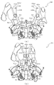
次いで、図6から図13を参照して、動作ユニット200について説明する。まず、図6から図9を参照して、背面ケース210への各ユニット300〜800の収容構造について説明する。   Next, the operation unit 200 will be described with reference to FIGS. First, with reference to FIGS. 6 to 9, a housing structure for the units 300 to 800 in the back case 210 will be described.

図6は、動作ユニット200の正面斜視図であり、図7から図9は、分解した動作ユニット200を正面視した動作ユニット200の分解正面斜視図である。なお、図8では、揺動動作ユニット800、円環動作ユニット700及び第1結合動作ユニット500が背面ケース210に装着された状態が図示され、図9では、図8に示す装着状態に加えて更に第2結合動作ユニット600及び複合動作ユニット400が背面ケース210に装着された状態が図示される。   6 is a front perspective view of the operation unit 200, and FIGS. 7 to 9 are exploded front perspective views of the operation unit 200 when the operation unit 200 is viewed from the front. 8 illustrates a state in which the swing operation unit 800, the annular operation unit 700, and the first combined operation unit 500 are mounted on the back case 210. In FIG. 9, in addition to the mounting state illustrated in FIG. Further, a state in which the second combined operation unit 600 and the composite operation unit 400 are mounted on the back case 210 is illustrated.

図6から図9に示すように、動作ユニット200は、底壁部211と、その底壁部211の外縁から立設される外壁部212とから一面側(図7紙面手前側)が開放された箱状に形成される背面ケース210を備える。背面ケース210は、その底壁部211の中央に矩形状の開口211aが開口形成されることで、正面視矩形の枠状に形成される。開口211aは、第3図柄表示装置81(図2参照)の外形に対応した(即ち、第3図柄表示装置81を配設可能な)大きさに形成される。   As shown in FIGS. 6 to 9, the operation unit 200 is opened on one side (the front side in FIG. 7) from the bottom wall portion 211 and the outer wall portion 212 erected from the outer edge of the bottom wall portion 211. A back case 210 formed in a box shape is provided. The rear case 210 is formed in a rectangular frame shape when viewed from the front by forming a rectangular opening 211a at the center of the bottom wall portion 211 thereof. The opening 211a is formed in a size corresponding to the outer shape of the third symbol display device 81 (see FIG. 2) (that is, the third symbol display device 81 can be disposed).

動作ユニット200は、背面ケース210の内部空間に、回転動作ユニット300、複合動作ユニット400、第1結合動作ユニット500、第2結合動作ユニット600、円環動作ユニット700及び揺動動作ユニット800がそれぞれ収容され、これを1ユニットとして構成される。   The operation unit 200 includes a rotation operation unit 300, a composite operation unit 400, a first combined operation unit 500, a second combined operation unit 600, an annular operation unit 700, and a swing operation unit 800 in the inner space of the rear case 210. It is accommodated and is configured as one unit.

具体的には、第1結合動作ユニット500は開口211aの上方となる位置において、円環動作ユニット700は開口211aの下方となる位置において、揺動動作ユニット800は開口211aの左右となる位置において、それぞれ背面ケース210の底壁部211に配設される(図8参照)。   Specifically, the first combined operation unit 500 is at a position above the opening 211a, the annular operation unit 700 is at a position below the opening 211a, and the swing operation unit 800 is at a position at the left and right of the opening 211a. These are respectively disposed on the bottom wall portion 211 of the back case 210 (see FIG. 8).

この図8に示す状態に対し、第2結合動作ユニット600は円環動作ユニット700の前面側に、複合動作ユニット500は揺動動作ユニット800の前面側に、それぞれ重ね合わされた積層状態で配設され、背面ケース210に収容される(図9参照)。この図9に示す状態に対し、回転動作ユニット300が第2結合動作ユニット600の前面側に重ね合わされた積層状態で配設され、背面ケース210に収容される(図6参照)。   In contrast to the state shown in FIG. 8, the second combined operation unit 600 is disposed on the front surface side of the annular operation unit 700, and the composite operation unit 500 is disposed on the front surface side of the swing operation unit 800 in a stacked state. And accommodated in the back case 210 (see FIG. 9). In contrast to the state shown in FIG. 9, the rotary operation unit 300 is disposed in a stacked state on the front side of the second combined operation unit 600 and is accommodated in the back case 210 (see FIG. 6).

このように、本実施形態では、所定の動作ユニット(例えば、第2結合動作ユニット600)に対し、他の動作ユニット(例えば、回転動作ユニット300)が前面側に重ね合わされた積層状態で配設されるので、正面視において、所定の動作ユニットの少なくとも一部(例えば、第2結合動作ユニット600の表ケース体612、図42参照)を、他の動作ユニットによって遮蔽することができる。   Thus, in the present embodiment, a predetermined operation unit (for example, the second combined operation unit 600) is arranged in a stacked state in which another operation unit (for example, the rotation operation unit 300) is superimposed on the front side. Therefore, in a front view, at least a part of the predetermined operation unit (for example, the front case body 612 of the second combined operation unit 600, see FIG. 42) can be shielded by another operation unit.

言い換えれば、遊技盤13が光透過性材料から形成され、その遊技盤13の背面側に配設される動作ユニットを遊技者が視認可能とされる場合に、所定の動作ユニットの必要な部分のみを遊技者に視認させ、他の部分を他の動作ユニットにより遊技者から遮蔽することができる。これにより、他の動作ユニットによって遮蔽される所定の演出部材については、その全体が遊技者から視認されることを前提として設計する必要がないので、その設計の自由度の向上を図ることができる。   In other words, when the game board 13 is formed of a light transmissive material and the player can visually recognize the operation unit disposed on the back side of the game board 13, only a necessary part of the predetermined operation unit is required. Can be visually recognized by the player, and other parts can be shielded from the player by other operation units. Thereby, since it is not necessary to design the predetermined effect member shielded by the other operation unit on the assumption that the whole is visually recognized by the player, the degree of freedom in the design can be improved. .

次いで、図10から図13を参照して、各ユニット300〜800の動作態様の概略について説明する。なお、図10から図13の説明においては、図6から図9を適宜参照する。   Next, an outline of an operation mode of each of the units 300 to 800 will be described with reference to FIGS. 10 to 13. In the description of FIGS. 10 to 13, FIGS. 6 to 9 are appropriately referred to.

図10から図13は、動作ユニット200の正面図である。なお、図10では円環動作ユニット700の円環形成部材790が結合位置に配置された状態が、図11では揺動動作ユニット800のアーム部材820が張出位置に配置された状態が、図12では第1結合動作ユニット500の第1係合部材539及び第2結合動作ユニット600の第2結合部材630が結合位置に配置された状態が、図13では複合動作ユニット400の動作部材491,492が張出位置に配置された状態が、それぞれ図示される。   10 to 13 are front views of the operation unit 200. FIG. 10 shows a state in which the ring forming member 790 of the ring operation unit 700 is arranged at the coupling position, and FIG. 11 shows a state in which the arm member 820 of the swing operation unit 800 is arranged in the extended position. 12 shows a state in which the first engagement member 539 of the first coupling operation unit 500 and the second coupling member 630 of the second coupling operation unit 600 are arranged at the coupling position. In FIG. The state in which 492 is disposed at the overhang position is illustrated.

円環動作ユニット700は、一対の円環形成部材790を備え、これら一対の円環形成部材790を、図8に示す退避位置と図10に示す結合位置との間で動作(変位)させる。図8に示す退避位置では、一対の円環形成部材790は、左右に振り分けられつつ、回転動作ユニット300の背面側に退避され、遊技者から視認不能とされる(図6参照)。一方、図10に示す結合位置では、一対の円環形成部材790は、背面ケース210の開口211a中央(即ち、第3図柄表示装置81の正面)に配置されると共に、互いに結合される(一対の円環形成部材790により円環形状が形成される)。   The ring operating unit 700 includes a pair of ring forming members 790 and moves (displaces) the pair of ring forming members 790 between the retracted position shown in FIG. 8 and the coupled position shown in FIG. In the retracted position shown in FIG. 8, the pair of ring forming members 790 are retracted to the back side of the rotational operation unit 300 while being distributed to the left and right, and are not visible to the player (see FIG. 6). On the other hand, at the coupling position shown in FIG. 10, the pair of ring forming members 790 is disposed at the center of the opening 211a of the back case 210 (that is, the front of the third symbol display device 81) and coupled to each other (a pair of pairs). The annular shape is formed by the annular forming member 790 of FIG.

揺動動作ユニット800は、揺動(回転)可能に形成される一対のアーム部材820を備え、これら一対のアーム部材820を、図8に示す退避位置と図11に示す張出位置との間で動作(変位)させる。図8に示す退避位置では、一対のアーム部材820は、複合動作ユニット400の背面側に退避され、遊技者から視認不能とされる(図6参照)。一方、図11に示す張出位置では、一対のアーム部材820は、背面ケース210の開口211a内(即ち、第3図柄表示装置81の正面)にその先端を張り出させる。   The swing operation unit 800 includes a pair of arm members 820 formed so as to be swingable (rotatable). The pair of arm members 820 are disposed between a retracted position illustrated in FIG. Operate (displace) with. In the retracted position shown in FIG. 8, the pair of arm members 820 are retracted to the back side of the combined operation unit 400 and are invisible to the player (see FIG. 6). On the other hand, at the projecting position shown in FIG. 11, the pair of arm members 820 project their tips into the opening 211a of the back case 210 (that is, the front of the third symbol display device 81).

第1結合動作ユニット500及び第2結合動作ユニット600は、第1係合部材539及び一対の第2結合部材630をそれぞれ備え、これら第1係合部材539及び一対の第2結合部材630を図9に示す退避位置と図12に示す結合位置との間で動作(変位)させる。図9に示す退避位置では、第1係合部材539は複合動作ユニット400の背面側に退避されると共に、第2結合部材630は複合動作ユニット400の背面側に退避され、それぞれ遊技者から視認不能とされる(図6参照)。一方、図12に示す結合位置では、第1係合部材539及び一対の第2結合部材630が背面ケース210の開口211a中央(即ち、第3図柄表示装置81の正面)に配置されると共に、互いに結合される。   The first coupling operation unit 500 and the second coupling operation unit 600 include a first engagement member 539 and a pair of second coupling members 630, respectively. The first engagement member 539 and the pair of second coupling members 630 are illustrated in FIG. 9 is moved (displaced) between the retracted position shown in FIG. 9 and the coupling position shown in FIG. In the retracted position shown in FIG. 9, the first engaging member 539 is retracted to the back side of the composite operation unit 400, and the second coupling member 630 is retracted to the back side of the composite operation unit 400, and is visually recognized by the player. It is disabled (see FIG. 6). On the other hand, in the coupling position shown in FIG. 12, the first engagement member 539 and the pair of second coupling members 630 are disposed at the center of the opening 211a of the back case 210 (that is, the front of the third symbol display device 81). Combined with each other.

複合動作ユニット400は、揺動(回転)可能に形成される4本の部材(動作部材491,492)を備え、これら4本の部材(動作部材491,492)を、図9に示す退避位置と図13に示す張出位置との間で動作(変位)させる。図9に示す退避位置では、4本の部材(動作部材491,492)は、背面ケース210の開口211a(即ち、第3図柄表示装置81)の側方に退避され、2本一組がそれぞれ上下方向に沿って直線状に整列した姿勢に配置される。一方、図13に示す張出位置では、4本の部材(動作部材491,492)は、背面ケース210の開口211a内(即ち、第3図柄表示装置81の正面)にその先端を張り出させ、開口211aの中央からそれぞれ放射直線状に延びる姿勢に配置される。   The composite operation unit 400 includes four members (operation members 491 and 492) formed so as to be able to swing (rotate), and these four members (operation members 491 and 492) are moved to the retracted position shown in FIG. And is moved (displaced) between the overhang positions shown in FIG. In the retracted position shown in FIG. 9, the four members (operation members 491 and 492) are retracted to the side of the opening 211a of the back case 210 (that is, the third symbol display device 81), and each of the two members is a set. It arrange | positions at the attitude | position arranged in a straight line along the up-down direction. On the other hand, at the projecting position shown in FIG. 13, the four members (operation members 491 and 492) project their tips into the opening 211a of the back case 210 (that is, the front of the third symbol display device 81). , And are arranged in a posture extending radially from the center of the opening 211a.

回転動作ユニット300は、回転可能に形成される回転部材330を備え、その回転部材330を回転動作させる。なお、図10から図13に示すように、回転動作ユニット300の回転部材330は、定位置において回転動作され、また、複合動作ユニット400の動作部材491,492は、張出位置または退避位置のいずれの位置においても最前面に配置されるため、遊技盤13(図2参照)を介して、常に遊技者から視認可能とされる。   The rotation operation unit 300 includes a rotation member 330 formed to be rotatable, and rotates the rotation member 330. As shown in FIGS. 10 to 13, the rotating member 330 of the rotating operation unit 300 is rotated at a fixed position, and the operating members 491 and 492 of the combined operation unit 400 are in the extended position or the retracted position. Since it is arranged in the forefront at any position, it is always visible from the player via the game board 13 (see FIG. 2).

これら各動作ユニット300〜800は、それぞれ独立して動作可能に形成されると共に、上述したように、重ね合わされた(積層された)状態で配設されるので、各動作ユニット300〜800のうちの層を違えて配設されるものについては、同時に動作させることができる。即ち、図10から図13で例示したように、各動作ユニット300〜800をそれぞれ単体で動作させるだけでなく、これらの動作を組み合わせることができるので、その演出効果を高めることができる。   Each of these operation units 300 to 800 is formed so as to be able to operate independently, and as described above, the operation units 300 to 800 are arranged in a stacked state (stacked). Those arranged in different layers can be operated simultaneously. That is, as illustrated in FIGS. 10 to 13, not only each of the operation units 300 to 800 can be operated alone, but also these operations can be combined, so that the effect of production can be enhanced.

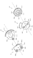
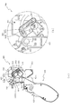
図14から図19を参照して、回転動作ユニット300について説明する。図14は、回転動作ユニット300の正面斜視図であり、図15は、回転動作ユニット300の背面図である。   The rotation operation unit 300 will be described with reference to FIGS. 14 to 19. FIG. 14 is a front perspective view of the rotational operation unit 300, and FIG. 15 is a rear view of the rotational operation unit 300.

回転動作ユニット300は、上述したように、遊技盤13(ベース板60)の背面側において、第1入賞口64(図2又は図5参照)に対応する位置(正面視において重なる位置)に配設される演出部材であり、正面中央に受入口361が開口され、第1入賞口64に入賞された球を、受入口361から受け入れ、案内通路380を介して、図示しない球排出路へ案内する。   As described above, the rotary operation unit 300 is arranged on the back side of the game board 13 (base plate 60) at a position corresponding to the first winning port 64 (see FIG. 2 or FIG. 5) (position overlapping in front view). An effect member to be installed, a receiving port 361 is opened in the center of the front, and a ball won in the first winning port 64 is received from the receiving port 361 and guided to a ball discharge path (not shown) through a guide passage 380. To do.

回転動作ユニット300の正面側には、正面視円環状の回転部材330と、装飾用の樹脂製部材である装飾部材370とが配設され、回転部材330の略中心部分には、受入口361(固定部材360)が配置される。回転部材330は、光透過性の樹脂材料から回転可能に形成され、その背面側に配設されたLEDの点灯や点滅を前面側へ透過させると共に、自身が回転されることで、第1入賞口64(図2又は図5参照)の周囲において、所定の演出を行う。   On the front side of the rotary operation unit 300, a rotary member 330 having an annular shape when viewed from the front and a decorative member 370 that is a resin member for decoration are disposed, and a receiving port 361 is provided at a substantially central portion of the rotary member 330. (Fixing member 360) is arranged. The rotating member 330 is formed of a light-transmitting resin material so as to be rotatable. The rotating member 330 transmits the lighting and blinking of the LED disposed on the back side thereof to the front side and is rotated to thereby receive the first prize. A predetermined effect is performed around the mouth 64 (see FIG. 2 or 5).

図16及び図17は、分解した回転動作ユニット300を正面視した回転動作ユニット300の分解正面斜視図である。なお、図16では、回転部材330のみを分解した状態が図示される。また、図17では、装飾部材370の図示が省略されると共に、第1歯車351と第3歯車353との一部が部分的に断面視される。   FIGS. 16 and 17 are exploded front perspective views of the rotary operation unit 300 as viewed from the front. Note that FIG. 16 illustrates a state where only the rotating member 330 is disassembled. In FIG. 17, the decorative member 370 is not shown, and a part of the first gear 351 and the third gear 353 are partially viewed in cross section.

図16及び図17に示すように、回転動作ユニット300は、その最背面側において骨格をなすケース体310と、そのケース体310に固着される電飾基部320と、その電飾基部320の正面側に配設される回転部材330と、その回転部材330に駆動モータ340の回転駆動力を伝達するための複数の歯車(第1歯車351、第2歯車352及び第3歯車353)と、それら複数の歯車のうちの第1歯車351をケース体310に固定するための固定部材360と、ケース体310の周囲に配設される装飾部材370と、を主に備えて構成される。   As shown in FIGS. 16 and 17, the rotary operation unit 300 includes a case body 310 that forms a skeleton on the back side, an electric decoration base 320 that is fixed to the case body 310, and a front surface of the electric decoration base 320. A rotating member 330 disposed on the side, a plurality of gears (first gear 351, second gear 352, and third gear 353) for transmitting the rotational driving force of the driving motor 340 to the rotating member 330, and A fixing member 360 for fixing the first gear 351 of the plurality of gears to the case body 310 and a decorative member 370 disposed around the case body 310 are mainly provided.

ケース体310は、電飾基部320に対応する正面視略円環状に形成される電飾基部取り付け部311と、その電飾基部取り付け部311よりも背面側に後退して形成される歯車取り付け部312と、それら電飾基部取り付け部311及びは歯車取り付け部312の外縁からそれぞれ外方へ延設される取り付け台座313とを主に備え、これらが樹脂材料から一体に形成される。   The case body 310 has an electric decoration base attachment portion 311 formed in a substantially circular shape in front view corresponding to the electric decoration base portion 320, and a gear attachment portion formed by retreating to the back side from the electric decoration base attachment portion 311. 312, the electric decoration base mounting portion 311, and the mounting base 313 extending outward from the outer edge of the gear mounting portion 312, respectively, which are integrally formed from a resin material.

電飾基部取り付け部311には、正面側に電飾基部320が、外周側に装飾部材370が、それぞれ締結ねじにより締結固定される。歯車取り付け部312は、第1歯車351から第3歯車353の外形にそれぞれ対応して凹設される正面視略円形状の3つの凹部が互いに連なって形成され、これら各凹部に第1歯車351から第3歯車353がそれぞれ収納(配設)される。   The electrical decoration base attaching part 311 is fastened and fixed with an electrical decoration base 320 on the front side and a decorative member 370 on the outer peripheral side with fastening screws. The gear attachment portion 312 is formed by connecting three concave portions having a substantially circular shape in front view that are formed corresponding to the outer shapes of the first gear 351 to the third gear 353, and the first gear 351 is formed in each of the concave portions. The third gears 353 are housed (arranged).

電飾基部取り付け部311の内周側には、歯車取り付け部312のうちの第1歯車351が収納される部位の上方に、開口311aが開口形成される。ケース体310に開口311aが形成されることで、かかる開口311aを介して、ケース体310の背面側から締結ねじにより第1歯車351(締結座部351d)に回転部材330(被締結部333)を締結固定することができる。よって、回転部材330の正面側に締結ねじが露出することを回避して、その外観の向上を図ることができる。   An opening 311 a is formed on the inner peripheral side of the electric decoration base mounting portion 311 above the portion of the gear mounting portion 312 that houses the first gear 351. By forming the opening 311a in the case body 310, the rotating member 330 (fastened portion 333) is connected to the first gear 351 (fastening seat portion 351d) from the back side of the case body 310 through the opening 311a by a fastening screw. Can be fastened and fixed. Therefore, it is possible to avoid the fastening screw from being exposed to the front side of the rotating member 330 and to improve the appearance thereof.

歯車取り付け部312には、第1歯車351が収納される凹部に、通過口314と、被締結部315と、挿通部316と、ガイド凸部317とがそれぞれ形成される。通過口314は、固定部材360の受入口361に連通される通路であり、固定部材360の受入口361から流入した球を、ケース体310の背面側に形成される案内通路380へ案内する。   In the gear mounting portion 312, a passage port 314, a fastened portion 315, an insertion portion 316, and a guide convex portion 317 are formed in the concave portion in which the first gear 351 is accommodated. The passage port 314 is a passage that communicates with the receiving port 361 of the fixing member 360, and guides a sphere that has flowed from the receiving port 361 of the fixing member 360 to a guide passage 380 formed on the back side of the case body 310.

なお、案内通路380は、ケース体310の背面に断面コ字状の部材が装着されることで、その装着された部材とケース体310の背面との間に球が通過可能な通路として形成される(図15参照)。案内通路380は、ケース体310の背面において通過口314に連通されると共に、下方へ向けて延設される。   The guide passage 380 is formed as a passage through which a sphere can pass between the attached member and the back surface of the case body 310 by attaching a U-shaped member to the back surface of the case body 310. (See FIG. 15). The guide passage 380 communicates with the passage port 314 on the back surface of the case body 310 and extends downward.

取り付け台座313には、挿通孔が穿設されており、その挿通孔に挿通された締結ねじを第2結合動作ユニット600の表ケース体612に締結することで、回転動作ユニット300が第2結合動作ユニット600を介して背面ケース210に締結固定される(図9及び図42参照)。   The mounting base 313 is provided with an insertion hole, and the fastening operation screw inserted into the insertion hole is fastened to the front case body 612 of the second coupling operation unit 600, whereby the rotational operation unit 300 is second coupled. It is fastened and fixed to the back case 210 via the operation unit 600 (see FIGS. 9 and 42).

被締結部315は、固定部材360を歯車取り付け部312に締結固定するための締結ねじが締結される部位(内周にめねじが刻設された凹部)であり、通過口314を挟んで左右非対称となる位置に一対が形成される(図18参照)。挿通部315は、歯車取り付け部312(ケース体310)を背面側の第2結合動作ユニット600の表ケース体612(図9及び図42参照)に締結固定するための締結ねじを挿通させるための貫通孔であり、通過口314の上方に形成される。   The fastened portion 315 is a portion to which a fastening screw for fastening and fixing the fixing member 360 to the gear attachment portion 312 is fastened (a concave portion in which a female screw is engraved on the inner periphery). A pair is formed at positions that are asymmetric (see FIG. 18). The insertion part 315 is used to insert a fastening screw for fastening and fixing the gear attachment part 312 (case body 310) to the front case body 612 (see FIGS. 9 and 42) of the second coupling operation unit 600 on the back side. It is a through hole and is formed above the passage opening 314.

ガイド凸部317は、第1歯車351の回転をガイド(案内)するためのレール状の部位であり、正面視円環状の凸部として歯車取り付け部312の正面から突設される。第1歯車351の背面には、ガイド部317に対応する正面視円環状のガイド凹部351eが凹設されており(図19参照)、そのガイド凹部351eにガイド突部317が嵌め入れられることで、歯車取り付け部312に対する第1歯車351の回転位置が規定される。   The guide convex portion 317 is a rail-shaped portion for guiding (guiding) the rotation of the first gear 351 and protrudes from the front of the gear mounting portion 312 as an annular convex portion when viewed from the front. An annular guide recess 351e corresponding to the guide portion 317 is formed on the back surface of the first gear 351 (see FIG. 19), and the guide protrusion 317 is fitted into the guide recess 351e. The rotational position of the first gear 351 relative to the gear mounting portion 312 is defined.

ここで、歯車取り付け部312は、ガイド凸部317に取り囲まれて形成される正面視円形状の領域において、通過口314が中心から下方にずれた位置(偏心した位置)に配設される一方、被締結部315が通過口314を挟んで左右に配設され、挿通部316が通過口314の上方に配設される。これにより、後述するように、限られたスペースにおいて締結固定のためのスペースを効率的に確保しつつ、ケース体310及び固定部材360の剛性を確保することができる。   Here, the gear mounting portion 312 is disposed at a position where the passage port 314 is shifted downward from the center (an eccentric position) in a circular area in a front view formed by being surrounded by the guide convex portion 317. The to-be-fastened portion 315 is disposed on the left and right sides of the passage port 314, and the insertion portion 316 is disposed above the passage port 314. Thereby, as will be described later, the rigidity of the case body 310 and the fixing member 360 can be ensured while efficiently securing a space for fastening and fixing in a limited space.

歯車取り付け部312には、第2歯車352が収納される凹部に、軸部318が突設される。軸部318は、第2歯車352を軸支するための軸体であり、第2歯車352の中心に穿設された軸孔352aに挿通される。なお、本実施形態では、第2歯車352の軸孔352aに挿通された軸部318の先端に、第2歯車352の抜け止めを設けることを省略可能に形成される。詳細については後述する。   A shaft portion 318 projects from the gear mounting portion 312 in a recess in which the second gear 352 is accommodated. The shaft portion 318 is a shaft body for supporting the second gear 352, and is inserted into a shaft hole 352 a drilled in the center of the second gear 352. In the present embodiment, it is possible to omit providing a stopper for the second gear 352 at the tip of the shaft portion 318 inserted through the shaft hole 352a of the second gear 352. Details will be described later.

歯車取り付け部312の背面には、第3歯車353が収納される凹部に対応する位置に、駆動モータ340が配設される。駆動モータ340は、その駆動軸340aを歯車取り付け部312の正面(第3歯車353が収納される凹部内)に突出させた状態で配設され、その駆動軸340aに第3歯車353が固着される。   A drive motor 340 is disposed on the back surface of the gear attachment portion 312 at a position corresponding to the concave portion in which the third gear 353 is accommodated. The drive motor 340 is disposed with its drive shaft 340a protruding in front of the gear mounting portion 312 (in the recess in which the third gear 353 is accommodated), and the third gear 353 is fixed to the drive shaft 340a. The

電飾基部320は、正面視円環状に形成されると共に正面側に複数のLED321aが実装される基板部321と、その基板部321の正面に配設されると共に基板部321の正面を複数の領域に区画する区画部322とを備えて構成される。   The electrical decoration base 320 is formed in an annular shape when viewed from the front, and a substrate portion 321 on which a plurality of LEDs 321a are mounted on the front side, and a front surface of the substrate portion 321 and a plurality of front surfaces of the substrate portion 321 are provided. And a partition portion 322 that partitions the region.

詳細には、区画部322は、基板部321の内縁および外縁に沿って延設される正面視環状の内縁リブ322a及び外縁リブ322bと、それら両リブ322a,322bの間に所定間隔を隔てつつ同心に形成される正面視環状の中間リブ322cと、これら各リブ322a〜322cの中心から径方向外方へ向けて放射直線状に延設される複数の放射リブ322dとが格子状に交差して配設される。なお、複数の放射リブ322dは、周方向等間隔(本実施形態では略30度間隔)に配設される。   In detail, the partition part 322 has a predetermined interval between the ribs 322a and 322b, and the inner edge rib 322a and the outer edge rib 322b which are annular in front view and extend along the inner edge and the outer edge of the substrate part 321. An intermediate rib 322c that is concentrically formed in a front view and a plurality of radiating ribs 322d that extend radially outward from the center of the ribs 322a to 322c intersect in a grid pattern. Arranged. The plurality of radiation ribs 322d are arranged at equal intervals in the circumferential direction (approximately 30 degrees in the present embodiment).

よって、本実施形態では、電飾基部320には、内周側に12個および外周側に12個の合計24個の領域が区画部322により区画され、それら区画された各領域には、それぞれ1乃至2個のLED321aが配設される。これにより、各LED321aをそれぞれ個別に点灯や点滅させる際には、その点灯や点滅に関連する領域と関連しない領域との間で明暗の差を大きくすることができ、その結果、演出効果を高めることができる。   Therefore, in the present embodiment, the electric decoration base 320 is divided into a total of 24 regions, 12 on the inner peripheral side and 12 on the outer peripheral side by the partitioning portion 322, and each of the partitioned regions includes One or two LEDs 321a are disposed. Accordingly, when each LED 321a is individually turned on or blinked, the difference in brightness between the area associated with the illumination or blinking and the area not associated with can be increased, and as a result, the production effect is enhanced. be able to.

回転部材330は、中心に開口が形成される正面視円環状の回転本体331と、その回転本体331の外縁から軸方向に延設される円筒状の外壁部332とを備え、これらが光透過性の樹脂材料から一体に形成される。回転本体331の中心に形成される開口の内径は、固定部材360の外径に対応されており、組み立て状態では、回転本体331の開口内に固定部材360が収容される(図14参照)。   The rotary member 330 includes a rotary main body 331 having an annular shape when viewed from the front, and a cylindrical outer wall portion 332 extending in the axial direction from the outer edge of the rotary main body 331, which are light transmissive. It is integrally formed from a compatible resin material. The inner diameter of the opening formed at the center of the rotating body 331 corresponds to the outer diameter of the fixing member 360, and the fixing member 360 is accommodated in the opening of the rotating body 331 in the assembled state (see FIG. 14).

回転本体331の背面には、被締結部333が複数箇所(本実施形態では3箇所)に形成される。被締結部333は、回転本体331(回転部材330)を第1歯車351に締結固定するための締結ねじが締結される部位(内周にめねじが刻設された凹部)であり、回転本体331の中心からそれぞれ同距離となる位置であって、周方向に不等間隔となる位置に配設される。   Fastened portions 333 are formed at a plurality of locations (three locations in the present embodiment) on the back surface of the rotating body 331. The to-be-fastened portion 333 is a portion to which a fastening screw for fastening and fixing the rotating body 331 (the rotating member 330) to the first gear 351 is fastened (a concave portion in which a female screw is engraved on the inner periphery). They are arranged at the same distance from the center of 331 and at unequal intervals in the circumferential direction.

回転本体331の正面には、正面視環状に形成されると共にそれぞれ同心に配置される複数の環状突部331a〜331eと、それら環状突部331a〜331eの中心から径方向外方へ向けて放射直線状に延設される複数の放射突部331fとが突設される。なお、複数の放射突部331fは、周方向等間隔(本実施形態では略30度間隔)に配設される。即ち、本実施形態では、放射突部331fの周方向間隔が、電飾基部320の放射リブ322dの周方向間隔に一致される。   A plurality of annular protrusions 331a to 331e that are formed in an annular shape in front view and are concentrically arranged on the front surface of the rotating body 331, and radiate radially outward from the centers of the annular protrusions 331a to 331e. A plurality of radiation projections 331f extending in a straight line are projected. The plurality of radiation protrusions 331f are arranged at equal intervals in the circumferential direction (approximately 30 degrees in the present embodiment). That is, in the present embodiment, the circumferential interval of the radiation projections 331f is matched with the circumferential interval of the radiation ribs 322d of the electrical decoration base 320.

回転本体331は、全体に均等の肉厚(厚み寸法)に形成されており、環状突部331a〜331e又は放射突部331fが突設される部分では、その突設される分だけ肉厚(厚み寸法)が厚く(大きく)される。よって、これら各突部331a〜331fが突設される部分において、光を透過しにくくすることができる。   The rotary main body 331 is formed to have a uniform thickness (thickness dimension) as a whole, and the portion where the annular projections 331a to 331e or the radiation projection 331f are projected is thicker by the projected amount ( (Thickness dimension) is made thicker (larger). Therefore, it is possible to make it difficult to transmit light at the portion where the protrusions 331a to 331f are provided.

この場合、回転動作ユニット300の組み立て状態では、径方向の最外方に位置する環状突部331eに対応する位置(正面視において重なる位置)に区画部材322の外縁リブ322bが、環状突部331dの次に径方向外方に位置する部位であって環状突部331d及び環状突部331cの間に対応する位置(正面視において重なる位置)に区画部材322の中間リブ322cが、それぞれ配置される。   In this case, in the assembled state of the rotary operation unit 300, the outer edge rib 322b of the partition member 322 is located at the position corresponding to the annular protrusion 331e located at the radially outermost position (the position overlapping in the front view), and the annular protrusion 331d. Next, the intermediate ribs 322c of the partition members 322 are respectively arranged at positions that are located radially outward and corresponding to the positions between the annular protrusions 331d and 331c (positions that overlap in front view). .

このように、回転部材330には、電飾基部320の区画部材322により区画された各領域に対応する領域が、各突部331a〜331fにより区画されているので、電飾基部320の各LED321aをそれぞれ個別に点灯や点滅させる際には、その点灯や点滅に関連する領域と関連しない領域との間で明暗の差を大きくすることができ、その結果、演出効果を高めることができる。   Thus, since the area | region corresponding to each area | region divided by the division member 322 of the electrical decoration base 320 is divided by each protrusion 331a-331f in the rotation member 330, each LED321a of the electrical decoration base 320 is shown. When the lights are individually turned on or blinked, the difference in brightness between the areas associated with the lights and blinks and the areas not associated with can be increased, and as a result, the effect of production can be enhanced.

かかる領域の区画は、回転部材330においては、上述したように、環状突部331a〜331e及び放射突部331fを正面から突設させ、厚み寸法を大きくすることにより達成する。これにより、例えば、回転部材330の正面に領域を区画するための印刷を施したりや別部材を配設する必要がなく、回転部材330全体を単一色により形成できるので、製品コストの削減を図ることができるだけでなく、その演出効果を高めることができる。   As described above, the division of the region is achieved by projecting the annular protrusions 331a to 331e and the radiation protrusion 331f from the front and increasing the thickness dimension as described above. Thereby, for example, it is not necessary to perform printing for partitioning the area in front of the rotating member 330 or dispose another member, and the entire rotating member 330 can be formed in a single color, thereby reducing the product cost. Not only can be improved, but the effect of the production can be enhanced.

回転部材330は、外壁部332の内径寸法が、電飾基部320の区画部材322(外縁リブ322b)の外径寸法と略同一または若干大きな寸法に設定され、組み立て状態では、外壁部332の内周側に電飾基部320の区画部材322が内嵌される構造とされる。これにより、LED321aの光が区画部材322の外周側から漏れることを抑制し、正面側への光の照射を効率良く行わせることができる。また、第1歯車351に回転部材330を締結固定する際には、外壁部332に区画部材322が内嵌される構造とすることで、かかる内嵌状態とすることで、両者を芯合わせさせた状態で相対回転させることができる。即ち、両者を相対回転させるのみで、第1歯車351の各締結座部351d(挿通孔)に対して回転部材330の各被締結部333を位置合わせすることができ、径方向の位置を調整する必要がないので、その分、作業性の向上を図ることができる。   In the rotating member 330, the inner diameter of the outer wall portion 332 is set to be substantially the same as or slightly larger than the outer diameter of the partition member 322 (outer edge rib 322b) of the electric decoration base 320. It is set as the structure by which the division member 322 of the electrical decoration base 320 is fitted by the circumference side. Thereby, it can suppress that the light of LED321a leaks from the outer peripheral side of the division member 322, and can perform light irradiation to the front side efficiently. In addition, when the rotating member 330 is fastened and fixed to the first gear 351, the partition member 322 is fitted in the outer wall portion 332, so that the inner fitting state is achieved by setting the inner fitting state. Can be rotated relative to each other. In other words, each of the fastened portions 333 of the rotating member 330 can be aligned with each of the fastening seat portions 351d (insertion holes) of the first gear 351 by simply rotating both of them, and the radial position can be adjusted. Therefore, the workability can be improved accordingly.

第1歯車351は、中心に開口を有しその開口内に固定部材360が挿通可能とされる正面視円環状の第1本体351aと、その第1本体351aの外周面に刻設される歯351bと、その歯351bよりも第1歯車351の正面側(回転部材330側)となる位置で第1本体351aの外周面からフランジ状に張り出す第1フランジ部351cと、その第3フランジ部351cよりも第1歯車351の正面側(回転部材330側)となる位置で第1本体351aの外周面から張り出す複数(本実施形態では3個)の締結座部351dと、第1本体351aの背面側に凹設され歯車取り付け部312のガイド凸部317が挿通されるガイド凹部351e(図19参照)と、を備え、固定部材360が歯車取り付け部312に締結固定されることで、その固定部材360と歯車取り付け部312との間で回転可能に保持される。   The first gear 351 has an opening in the center, and a first body 351a having an annular shape in front view in which the fixing member 360 can be inserted into the opening, and teeth engraved on the outer peripheral surface of the first body 351a 351b, a first flange portion 351c projecting in a flange shape from the outer peripheral surface of the first main body 351a at a position closer to the front side (rotating member 330 side) of the first gear 351 than the teeth 351b, and a third flange portion thereof A plurality (three in this embodiment) of fastening seat portions 351d projecting from the outer peripheral surface of the first main body 351a at a position closer to the front side (rotating member 330 side) of the first gear 351 than the 351c, and the first main body 351a. And a guide recess 351e (see FIG. 19) through which the guide protrusion 317 of the gear mounting portion 312 is inserted, and the fixing member 360 is fastened and fixed to the gear mounting portion 312. In, rotatably held between its fixing member 360 and the gear attachment portion 312.

第1歯車351は、第1本体351aの外周面から第1フランジ部351cが張り出して形成されるので、かかる第1フランジ部351cにより第1歯車351の剛性を高めることができる。特に、本実施形態では、第1フランジ部351cが歯351bの軸方向端面に連設されるので、歯351bの剛性を高めることができる。その結果、第2歯車352との間の歯合状態を適正として、伝達効率の向上を図ることができると共に歯351b,352bの耐久性の向上を図ることができる。また、第1フランジ部351cは、後述するように、第2歯車352の抜け止めを兼用するので、その分、抜け止め用の部品を省略して、部品コストの削減が図ることができる。   Since the first gear 351 is formed by extending the first flange portion 351c from the outer peripheral surface of the first main body 351a, the rigidity of the first gear 351 can be increased by the first flange portion 351c. In particular, in the present embodiment, since the first flange portion 351c is connected to the axial end surface of the tooth 351b, the rigidity of the tooth 351b can be increased. As a result, it is possible to improve the transmission efficiency and to improve the durability of the teeth 351b and 352b by making the meshing state with the second gear 352 appropriate. Further, as will be described later, the first flange portion 351c also serves to prevent the second gear 352 from coming off, and accordingly, parts for retaining can be omitted and the cost of parts can be reduced.

締結座部351dは、回転本体331(回転部材330)の被締結部333に締結固定される部位であり、回転本体331の各被締結部333に対応する位置にそれぞれ配設される。即ち、各締結座部351dには、被締結部333に締結する締結ねじを挿通させるための挿通孔が穿設されており、その挿通孔は、第1歯車351の中心からそれぞれ同距離となる位置であって、周方向に不等間隔となる位置に配設される。よって、第1歯車351と回転部材330とは、1の位相位置のみで締結固定が可能となるので、第1歯車351に回転部材330を組み付ける際には、その周方向位置を作業者が間違えて組み付けることを回避できる。   The fastening seat portion 351d is a portion that is fastened and fixed to the fastened portion 333 of the rotating body 331 (the rotating member 330), and is disposed at a position corresponding to each fastened portion 333 of the rotating body 331. That is, each fastening seat portion 351d is provided with an insertion hole for inserting a fastening screw to be fastened to the fastened portion 333, and the insertion holes are the same distance from the center of the first gear 351. It is disposed at a position that is unequally spaced in the circumferential direction. Therefore, the first gear 351 and the rotating member 330 can be fastened and fixed only at one phase position. Therefore, when the rotating member 330 is assembled to the first gear 351, the operator makes a mistake in the circumferential position. Can be avoided.

第1歯車351と回転部材330とを1の位相位置のみで締結固定を可能とするためには、必ずしも第1歯車351の中心からそれぞれ同距離となる位置に各締結座部351の挿通孔が配設されている必要はない。各締結座部351の挿通孔は、周方向に等間隔となる位置であって、回転本体331の中心からの距離がそれぞれ異なる位置に配設されていても良い。   In order to allow the first gear 351 and the rotating member 330 to be fastened and fixed only at one phase position, the insertion holes of the fastening seat portions 351 are not necessarily located at the same distance from the center of the first gear 351. It does not need to be arranged. The insertion holes of the fastening seat portions 351 may be arranged at positions that are equally spaced in the circumferential direction and that are different in distance from the center of the rotating body 331.

但し、本実施形態のように、第1歯車351の中心からそれぞれ同距離となる位置に各締結座部351の挿通孔を配設することが好ましい。即ち、各締結座部351dの長さ寸法(張り出し長さ)をそれぞれ同一とできるので、第1歯車351を樹脂材料から射出成形する場合には、その成形性の向上を図ることができるからである。   However, as in the present embodiment, it is preferable that the insertion holes of the respective fastening seat portions 351 are disposed at the same distance from the center of the first gear 351. That is, since the length dimension (extension length) of each fastening seat portion 351d can be made the same, when the first gear 351 is injection-molded from a resin material, the moldability can be improved. is there.

ここで、ケース体310の背面側から締結ねじを締結座部351dの挿通孔を介して回転部材330の被締結部333に締結固定するためには、ケース体310に開口311aを開口形成する必要がある。この場合、第1歯車351の中心からそれぞれ異なる距離に各締結部材351の挿通孔が配置される場合には、各挿通孔の移動軌跡が異なることとなり、その分、開口311aの開口幅を大きくする必要があるため、剛性の低下を招くところ、本実施形態によれば、各挿通孔の移動軌跡を同一とできるので、その分、開口311aの開口幅を最小に抑えることができる。

第2歯車352は、正面視円形状の第2本体352aと、その第2本体352aの外周面に刻設される歯352bと、第2本体352aの中心に穿設される軸孔352cとを供え、その軸孔352cに歯車取り付け部312の軸部318が挿通されることで、第1歯車351に歯合された状態で歯車取り付け部312に回転可能に保持される。
Here, in order to fasten and fix the fastening screw from the back side of the case body 310 to the fastened portion 333 of the rotating member 330 through the insertion hole of the fastening seat portion 351d, it is necessary to form an opening 311a in the case body 310. There is. In this case, when the insertion holes of the fastening members 351 are arranged at different distances from the center of the first gear 351, the movement trajectories of the insertion holes are different, and the opening width of the opening 311a is increased accordingly. However, according to the present embodiment, the movement trajectory of each insertion hole can be made the same, so that the opening width of the opening 311a can be minimized.

The second gear 352 includes a second main body 352a having a circular shape when viewed from the front, teeth 352b engraved on the outer peripheral surface of the second main body 352a, and a shaft hole 352c formed in the center of the second main body 352a. The shaft portion 318 of the gear attachment portion 312 is inserted into the shaft hole 352c, so that the gear attachment portion 312 is rotatably held in a state of being engaged with the first gear 351.

第3歯車353は、正面視円形状の第3本体353aと、その第3本体353aの外周面に刻設される歯353bと、その歯353bよりも第3歯車353の正面側(回転部材330側)となる位置で第3本体353aの外周面からフランジ状に張り出す第3フランジ部353cと、とを備え、第3本体353aに駆動モータ370の駆動軸340aが固着されることで、第2歯車352に歯合された状態で駆動モータ340の駆動軸340aに保持される。   The third gear 353 includes a third main body 353a having a circular shape when viewed from the front, teeth 353b engraved on the outer peripheral surface of the third main body 353a, and the front side of the third gear 353 with respect to the teeth 353b (the rotating member 330). And a third flange portion 353c projecting in a flange shape from the outer peripheral surface of the third main body 353a at a position of the third main body 353a, and the drive shaft 340a of the drive motor 370 is fixed to the third main body 353a. It is held on the drive shaft 340 a of the drive motor 340 while being engaged with the two gears 352.

よって、駆動モータ340が回転駆動され、第3歯車353が回転されると、その回転が第2歯車352に伝達され、第2歯車352が回転されると共に、その第2歯車352の回転が第1歯車351に伝達され、第1歯車351が回転される。その結果、第1歯車351に締結座部351d及び被締結部333を介して締結固定される回転部材330に駆動モータ340の駆動力が伝達され、かかる回転部材330が回転される。   Therefore, when the drive motor 340 is rotationally driven and the third gear 353 is rotated, the rotation is transmitted to the second gear 352, the second gear 352 is rotated, and the rotation of the second gear 352 is the first. The first gear 351 is rotated by being transmitted to the first gear 351. As a result, the driving force of the drive motor 340 is transmitted to the rotating member 330 fastened and fixed to the first gear 351 via the fastening seat portion 351d and the fastened portion 333, and the rotating member 330 is rotated.

なお、第1歯車351の場合と同様に、第3歯車353は、第3本体353aの外周面から第3フランジ部353cが張り出して形成されるので、かかる第3フランジ部353cにより第3歯車353の剛性を高めることができる。特に、本実施形態では、第3フランジ部353cが歯353bの軸方向端面に連設されるので、歯353bの剛性を高めることができる。その結果、第2歯車352との間の歯合状態を適正として、伝達効率の向上を図ることができると共に歯353b,352bの耐久性の向上を図ることができる。また、第3フランジ部353cは、後述するように、第2歯車352の抜け止めを兼用するので、その分、抜け止め用の部品を省略して、部品コストの削減が図ることができる。   As in the case of the first gear 351, the third gear 353 is formed by projecting the third flange portion 353c from the outer peripheral surface of the third main body 353a, and thus the third gear 353 is formed by the third flange portion 353c. The rigidity of can be increased. In particular, in the present embodiment, the third flange portion 353c is connected to the axial end surface of the tooth 353b, so that the rigidity of the tooth 353b can be increased. As a result, it is possible to improve the transmission efficiency and to improve the durability of the teeth 353b and 352b by making the meshing state with the second gear 352 appropriate. Further, as will be described later, the third flange portion 353c also serves to prevent the second gear 352 from coming off, and accordingly, parts for retaining can be omitted and the cost of parts can be reduced.

固定部材360は、第1歯車351を歯車取り付け部312に固定するための円柱状の部材であり、受入口361と、挿通部362とを備える。受入口361は、遊技盤13への装着状態において、第1入賞口64に連通される通路であり、第1入賞口64から流入した球を、歯車取り付け部312の通過口314へ案内する。挿通部362は、固定部材360を歯車取り付け部312の被締結部315又は挿通部316に締結または挿通する締結ねじを挿通させるための貫通孔である。   The fixing member 360 is a columnar member for fixing the first gear 351 to the gear attachment portion 312, and includes a receiving port 361 and an insertion portion 362. The receiving port 361 is a passage that communicates with the first winning port 64 when mounted on the game board 13, and guides the ball that has flowed from the first winning port 64 to the passing port 314 of the gear mounting portion 312. The insertion portion 362 is a through hole for inserting a fastening screw that fastens or inserts the fixing member 360 into the fastened portion 315 or the insertion portion 316 of the gear attachment portion 312.

図18(a)は、ケース体310の正面図であり、図18(b)は、固定部材360の正面図である。なお、図18(a)では、第1歯車351、第2歯車352及び第3歯車353がケース体310に配設された状態が図示されると共に、第1歯車351及び第3歯車353の一部が部分的に断面視される。   FIG. 18A is a front view of the case body 310, and FIG. 18B is a front view of the fixing member 360. 18A shows a state in which the first gear 351, the second gear 352, and the third gear 353 are disposed in the case body 310, and one of the first gear 351 and the third gear 353 is illustrated. The part is partly viewed in cross section.

図18(a)及び図18(b)に示すように、ケース体310の歯車取り付け部312に形成される通過口314は、上述したように、第1歯車351の中心から下方(図18(a)下側)に位置ずれして(偏心して)配置される。そのため、歯車取り付け部312は、通過口314の周囲に形成される円環状の領域において、通過口314の上方の幅寸法(図18(a)上下方向寸法)が下方の幅寸法に比較して広くされる。   As shown in FIGS. 18A and 18B, the passage port 314 formed in the gear attachment portion 312 of the case body 310 is downward from the center of the first gear 351 as described above (FIG. 18 ( a) Displaced (eccentric) to the lower side). For this reason, the gear mounting portion 312 has an annular region formed around the passage opening 314 in which the upper width dimension of the passage opening 314 (the vertical dimension in FIG. 18A) is smaller than the lower width dimension. Widened.

第1歯車351の内周側に挿通され、歯車取り付け部312に締結固定される固定部材360についても同様に、その固定部材360に形成される受入口361は、固定部材360の中心から下方(図18(b)下側)に位置ずれして(偏心して)配置される。そのため、固定部材360は、受入口361の周囲に形成される円環状の領域において、受入口361の上方の幅寸法(図18(b)上下方向寸法)が下方の幅寸法に比較して広くされる。   Similarly, with respect to the fixing member 360 inserted into the inner peripheral side of the first gear 351 and fastened and fixed to the gear mounting portion 312, the receiving port 361 formed in the fixing member 360 is downward (from the center of the fixing member 360 ( In FIG. 18B (lower side), it is displaced (eccentric). Therefore, in the annular region formed around the receiving port 361, the fixing member 360 has a wider width dimension (the vertical dimension in FIG. 18 (b)) than the lower width dimension. Is done.

このように、本実施形態では、通過口314及び受入口361を位置ずれ(偏心)させ、その周囲(円環状の領域)の一部に広い(幅寸法が大きくされた)部分を形成すると共に、その広くされた部分に挿通部316,362をそれぞれ配置(穿設)するので、限られたスペースを有効に活用して、大径の孔を穿設できると共に、かかる場合でも、ケース体310及び固定部材360の剛性を確保することができる。   As described above, in the present embodiment, the passage port 314 and the receiving port 361 are displaced (eccentric) to form a wide (increased width dimension) part of the periphery (annular region). Since the insertion portions 316 and 362 are respectively arranged (perforated) in the widened portion, a large-diameter hole can be perforated by making effective use of the limited space. And the rigidity of the fixing member 360 can be ensured.

即ち、挿通部316,362は、回転動作ユニット300を第2結合動作ユニット600の表ケース体612(図9又は図42参照)に締結固定するための締結ねじが挿通可能な孔として形成される部位であり、支持する重量が嵩むことから大径の締結ねじが挿通されるため、比較的大径の孔として形成される必要があるところ、上述のように、一部に広い(幅寸法が大きくされた)部分を形成することで、かかる部分を利用して、大径の孔を穿設するスペースを効率的に確保できる。一方で、このような大径の孔を穿設する場合でも、部分的に広くされた領域に孔が穿設されるため、その剛性を確保できる。   In other words, the insertion portions 316 and 362 are formed as holes through which fastening screws for fastening and fixing the rotary operation unit 300 to the front case body 612 (see FIG. 9 or 42) of the second combined operation unit 600 can be inserted. This is a part, and since the supporting weight increases, a large-diameter fastening screw is inserted, so it needs to be formed as a relatively large-diameter hole. By forming the enlarged portion, it is possible to efficiently secure a space for making a large-diameter hole by using the portion. On the other hand, even when such a large-diameter hole is drilled, the hole is drilled in a partially widened region, so that rigidity can be ensured.

図19は、第1歯車351、第2歯車352及び第3歯車353のケース体310による支持構造を模式的に図示する模式図であり、図18の矢印XIX方向視に対応する。なお、図19では、ケース体310が断面視されると共に、第1歯車351及び第2歯車352の一部が部分的に断面視される。   FIG. 19 is a schematic diagram schematically illustrating a support structure of the first gear 351, the second gear 352, and the third gear 353 by the case body 310, and corresponds to the view in the arrow XIX direction of FIG. In FIG. 19, the case body 310 is viewed in cross section, and a part of the first gear 351 and the second gear 352 is partially viewed in cross section.

図19に示すように、第1歯車351は、背面側に凹設されたガイド凹部351eに歯車取り付け部312のガイド凸部317が嵌め入れられることで、歯車取り付け部312に回転可能に支持される。また、第1歯車351は、歯車取り付け部312に締結固定される固定部材360によって、歯車取り付け部312から軸方向(図19上側)へ脱落することが規制される。一方、第3歯車353は、駆動モータ340の駆動軸340aに固着される。なお、固着の方法としては、例えば、圧入によるものや接着剤によるものが例示される。   As shown in FIG. 19, the first gear 351 is rotatably supported by the gear mounting portion 312 by fitting the guide convex portion 317 of the gear mounting portion 312 into a guide concave portion 351e that is recessed on the back side. The Further, the first gear 351 is restricted from falling off from the gear mounting portion 312 in the axial direction (upper side in FIG. 19) by a fixing member 360 fastened and fixed to the gear mounting portion 312. On the other hand, the third gear 353 is fixed to the drive shaft 340 a of the drive motor 340. Note that examples of the fixing method include press-fitting and an adhesive.

第2歯車352は、第2本体352aに穿設される軸孔352cに歯車取り付け部312の軸部318が挿通されることで、その歯352bが第1歯車351及び第3歯車353の歯351b,353bに歯合された状態で、歯車取り付け部312に回転可能に軸支される。   The second gear 352 has the teeth 352b of the first gear 351 and the third gear 353 of the third gear 353 when the shaft portion 318 of the gear mounting portion 312 is inserted into the shaft hole 352c formed in the second main body 352a. , 353b and is rotatably supported by the gear mounting portion 312.

この場合、上述したように、第1歯車351及び第3歯車353には、それら第1本体351a及び第3本体353aの外周面から径方向外方へ張り出す第1フランジ部351c及び第3フランジ部353cがそれぞれ形成されており、これら第1フランジ部351c及び第3フランジ部353cは、第2歯車352の軸方向端面に重なる位置まで張り出されている。これにより、第2歯車352が、歯車取り付け部312の軸部318から軸方向(図19上側)へ抜け出ることを規制することができる。その結果、抜け止め用の部品を軸部318の先端に配設する必要がないので、その分、部品点数を削減して、部品コストを抑えることができる。また、組み立て時には、第2歯車352については、歯車取り付け部312の軸部318を軸孔352cに挿通させるだけで良く、抜け止めの部品を装着する工程を省略できるので、その分、製造コストを抑えることができる。   In this case, as described above, the first gear 351 and the third gear 353 include the first flange portion 351c and the third flange that project radially outward from the outer peripheral surfaces of the first main body 351a and the third main body 353a. The portions 353c are formed, and the first flange portion 351c and the third flange portion 353c are extended to a position overlapping the end surface in the axial direction of the second gear 352. Thereby, it is possible to restrict the second gear 352 from coming out from the shaft portion 318 of the gear mounting portion 312 in the axial direction (upper side in FIG. 19). As a result, there is no need to dispose a retaining part at the tip of the shaft portion 318, and accordingly, the number of parts can be reduced and the part cost can be reduced. Further, at the time of assembling, the second gear 352 can be simply inserted through the shaft hole 352c of the shaft portion 318 of the gear mounting portion 312 and the step of attaching the retaining component can be omitted, thereby reducing the manufacturing cost. Can be suppressed.

本実施形態では、第1歯車351の第1フランジ部351cと第3歯車353の第3フランジ部353cとが第2歯車352に対して異なる2箇所で当接するので、第2歯車352が軸方向へ抜け出ることを確実に規制できるだけでなく、かかる第2歯車352が軸部318に対して傾斜しながら回転することを抑制できる。その結果、第2歯車352の歯352bと第1歯車351及び第3歯車353の歯351b,353bとの歯合状態を適正として、伝達効率の向上と耐久性の向上とを図ることができる。特に、第2歯車352に当接する2箇所は位相を約180度異ならせる位置に設定されるので、上述した効果をより顕著に発揮できる。なお、2箇所の位相は、約160度から約180度の範囲内に設定されることが好ましい。   In the present embodiment, since the first flange portion 351c of the first gear 351 and the third flange portion 353c of the third gear 353 abut against the second gear 352 at two different locations, the second gear 352 is axially moved. It is possible not only to reliably control the escape, but also to prevent the second gear 352 from rotating while being inclined with respect to the shaft portion 318. As a result, the meshing state of the teeth 352b of the second gear 352 and the teeth 351b and 353b of the first gear 351 and the third gear 353 can be made appropriate to improve transmission efficiency and durability. In particular, since the two locations in contact with the second gear 352 are set at positions where the phases differ by about 180 degrees, the above-described effects can be exhibited more remarkably. The two phases are preferably set within a range of about 160 degrees to about 180 degrees.

ここで、第1歯車351及び第3歯車353の第1フランジ部351c及び第3フランジ部353cは、歯351b及び歯353bの谷よりも山頂側に張り出されていれば足りる。歯351b及び歯353の谷よりも張り出されていれば、第2歯車352の歯352bの山頂側の端面に当接できるからである。また、第1フランジ部351c及び第3フランジ部353cの形成に要する材料を抑制して、軽量化および材料コストの削減を図ることができるからである。但し、第1フランジ部351c及び第3フランジ部353cは、歯351b及び歯353の山頂側よりも更に径方向外方へ張り出されていることが好ましい。第2歯車352の傾斜をより確実に抑制できるからである。   Here, it is sufficient that the first flange portion 351c and the third flange portion 353c of the first gear 351 and the third gear 353 are projected to the mountain top side from the valleys of the teeth 351b and the teeth 353b. This is because if it protrudes beyond the valleys of the teeth 351b and the teeth 353, it can come into contact with the end face on the mountain top side of the teeth 352b of the second gear 352. Moreover, it is because the material required for formation of the 1st flange part 351c and the 3rd flange part 353c can be suppressed, and weight reduction and reduction of material cost can be aimed at. However, it is preferable that the first flange portion 351c and the third flange portion 353c protrude further outward in the radial direction than the crests of the teeth 351b and the teeth 353. This is because the inclination of the second gear 352 can be more reliably suppressed.

次いで、図20から図30を参照して、複合動作ユニット400について説明する。   Next, the combined operation unit 400 will be described with reference to FIGS.

なお、複合動作ユニット400は、上述したように4本の部材(動作部材491,492)を備え(図7及び図13参照)、それら各部材(動作部材491,492)を動作(変位)させるための4つのユニットからなる。即ち、複合動作ユニット400は、背面ケース210の正面視において、開口211aの左側に上下方向に沿って列設される2つのユニットと、開口211aの右側に上下方向に沿って列設される2つのユニットからなる。この場合、各部材(動作部材491,492)を動作(変位)させるための構造(技術思想)は4つのユニットにおいてそれぞれ同一であるので、以下においては、これら4つのユニットのうちの1のユニット(開口211aの右側上方に配設されるユニット、図7及び図13参照)を複合動作ユニット400と称して説明する。   The composite operation unit 400 includes the four members (operation members 491 and 492) as described above (see FIGS. 7 and 13), and operates (displaces) each of these members (operation members 491 and 492). It consists of four units. That is, in the front view of the back case 210, the composite operation unit 400 is arranged in two units arranged in the vertical direction on the left side of the opening 211a, and 2 arranged in the vertical direction on the right side of the opening 211a. Consists of two units. In this case, since the structure (technical idea) for operating (displacement) each member (the operation members 491, 492) is the same in the four units, one unit of these four units will be described below. (A unit disposed on the upper right side of the opening 211a, see FIGS. 7 and 13) will be referred to as a combined operation unit 400.

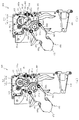
図20は、複合動作ユニット400の正面斜視図である。図20に示すように、複合動作ユニット400は、取り付けベース410の前面側に動作部材491,492が配設され、この動作部材491,492に開閉動作および回転動作を複合的に行わせる(図27参照)。即ち、動作部材491,492は、互いの長手方向を平行とする姿勢で対向配置されており、その対向間隔を拡大縮小させる動作(開閉動作)と、取り付けベース410に配設される基部側を中心として回転する動作(回転動作)とが実行可能に形成される。なお、取り付けベース410の前面には、装飾体として形成される装飾部材411が配設される。   FIG. 20 is a front perspective view of the composite operation unit 400. As shown in FIG. 20, in the combined operation unit 400, operating members 491 and 492 are disposed on the front side of the mounting base 410, and the operating members 491 and 492 perform opening / closing operations and rotating operations in combination (see FIG. 20). 27). In other words, the operation members 491 and 492 are arranged to face each other with their longitudinal directions parallel to each other, and an operation (opening / closing operation) for enlarging / reducing the facing interval and a base side arranged on the mounting base 410 are arranged. An operation that rotates about the center (rotation operation) is formed to be executable. A decorative member 411 formed as a decorative body is disposed on the front surface of the mounting base 410.

本実施形態では、動作部材491,492の2種類の動作態様(開閉動作および回転動作)を1の駆動モータ430により実行が可能となるように形成される。そのため、2種類の動作態様に対して駆動モータ430を個別に設ける必要がなく、その分、製品コストの削減を図ることができる。かかる構造の詳細構成について、図21から図23を参照して説明する。   In the present embodiment, two types of operation modes (opening / closing operation and rotation operation) of the operation members 491 and 492 can be executed by one drive motor 430. Therefore, it is not necessary to provide the drive motor 430 separately for the two types of operation modes, and the product cost can be reduced accordingly. A detailed configuration of such a structure will be described with reference to FIGS.

図21は、分解した複合動作ユニット400を正面視した複合動作ユニット400の分解正面斜視図である。また、図22は、複合動作ユニット400の一部を分解した状態における複合動作ユニット400の分解斜視図であり、図22左側に図示される構成が正面視されると共に図22右側に図示される構成が背面視される。なお、図21及び図22では、装飾部材411の図示が省略されると共に、図22では、取り付けベース410の図示が省略される。   FIG. 21 is an exploded front perspective view of the combined operation unit 400 when the combined operation unit 400 is viewed from the front. 22 is an exploded perspective view of the composite operation unit 400 in a state in which a part of the composite operation unit 400 is disassembled. The configuration shown on the left side of FIG. 22 is viewed from the front and shown on the right side of FIG. The configuration is viewed from the back. 21 and 22, the illustration of the decorative member 411 is omitted, and the illustration of the attachment base 410 is omitted in FIG. 22.

図21及び図22に示すように、複合動作ユニット400は、背面ケース210(図7参照)に配設される取り付けベース410と、その取り付けベース410に取り付けられる保持ケース420と、その保持ケース420に回転可能に軸支される複数の歯車と、それら複数の歯車を回転駆動力するための駆動力を発生する駆動モータ430と、保持ケース420に基端が回転可能に軸支される裏アーム体471及び表アーム体472と、それら裏アーム体471及び表アーム体472の対向面間に狭装されるスライドラック部材481、第1ピニオン脚部材482及び第2ピニオン脚部材483と、それら第1ピニオン脚部材482及び第2ピニオン脚部材483の先端に連結される動作部材491、492とを主に備える。   As shown in FIGS. 21 and 22, the composite operation unit 400 includes a mounting base 410 disposed on the back case 210 (see FIG. 7), a holding case 420 attached to the mounting base 410, and a holding case 420. A plurality of gears rotatably supported by the motor, a drive motor 430 that generates a driving force for rotating the plurality of gears, and a back arm whose base end is rotatably supported by the holding case 420 A body 471 and a front arm body 472, a slide rack member 481, a first pinion leg member 482, a second pinion leg member 483, and a second pinion leg member 483, which are disposed between the opposing surfaces of the back arm body 471 and the front arm body 472. Operation members 491 and 492 mainly connected to the tips of the first pinion leg member 482 and the second pinion leg member 483 are mainly provided.

保持ケース420は、取り付けベース410に取り付けられる裏ケース体421と、その裏ケース体421の正面側に対向配置される表ケース体422とを備え、それら裏ケース体421と表ケース体422との対向間に形成される内部空間に複数の歯車が回転可能に軸支されつつ収容される。   The holding case 420 includes a back case body 421 attached to the attachment base 410 and a front case body 422 disposed to face the front side of the back case body 421. The back case body 421 and the front case body 422 A plurality of gears are rotatably supported in an internal space formed between the opposing surfaces.

保持ケース420には、裏ケース体421の背面側に駆動モータ430が配設されると共に、裏ケース体421及び表ケース体422の対向間には、3本の回転軸(減速軸425、第1軸426及び第2軸427)がそれぞれ駆動モータ430の駆動軸と平行となる姿勢で架設され、これら減速軸425から第2軸427に複数の歯車が回転可能に軸支される。なお、駆動モータ430の駆動軸には、ピニオンギヤ431が固着される。   In the holding case 420, a drive motor 430 is disposed on the back side of the back case body 421, and three rotating shafts (a reduction shaft 425, a first shaft) are provided between the back case body 421 and the front case body 422. The first shaft 426 and the second shaft 427 are respectively installed in a posture parallel to the drive shaft of the drive motor 430, and a plurality of gears are rotatably supported from the reduction shaft 425 to the second shaft 427. A pinion gear 431 is fixed to the drive shaft of the drive motor 430.

複数の歯車は、減速軸425に軸支される減速歯車441と、第1軸426に軸支される開閉第1歯車451及び回転第1歯車461と、第2軸427に軸支される開閉第2歯車452及び回転第2歯車462とからなる(図24及び図25参照)。減速歯車441は、大径の歯車441aと、その大径の歯車441aに同軸に一体に形成される小径の歯車441bとを備え、ピニオンギヤ431の回転を減速させつつ開閉第1歯車451へ伝達する。ここで、図23を参照して、開閉第1歯車451、開閉第2歯車452、回転第1歯車461及び回転第2歯車462について説明する。   The plurality of gears are a reduction gear 441 supported by a reduction shaft 425, an opening / closing first gear 451 and a rotation first gear 461 supported by a first shaft 426, and an opening / closing supported by a second shaft 427. It consists of a second gear 452 and a rotating second gear 462 (see FIGS. 24 and 25). The reduction gear 441 includes a large-diameter gear 441a and a small-diameter gear 441b formed coaxially with the large-diameter gear 441a and transmits the rotation of the pinion gear 431 to the opening / closing first gear 451 while decelerating the rotation. . Here, with reference to FIG. 23, the opening / closing first gear 451, the opening / closing second gear 452, the rotating first gear 461 and the rotating second gear 462 will be described.

図23は、開閉第1歯車451、開閉第2歯車452、回転第1歯車461及び回転第2歯車462の正面斜視図である。開閉第1歯車451は、本体部451aと、その本体部451aに貫通形成され第1軸426が挿通される挿通孔451bと、その挿通孔451bを中心として本体部451aの外周に全周にわたって刻設される歯451cと、本体部451aの軸方向端面(正面)から突出され挿通孔451bを挟んで位置する一対の連結突部451dと、本体部451aに貫通形成され挿通孔451bの側方に位置する位置決め孔451eとを備える。   FIG. 23 is a front perspective view of the first open / close gear 451, the second open / close gear 452, the first rotation gear 461, and the second rotation gear 462. The opening / closing first gear 451 is formed on the outer periphery of the main body 451a around the main body 451a, the insertion hole 451b formed through the main body 451a and through which the first shaft 426 is inserted, and the insertion hole 451b as a center. Teeth 451c to be provided, a pair of connecting projections 451d protruding from the axial end face (front) of the main body 451a and sandwiching the insertion hole 451b, and penetratingly formed in the main body 451a to the side of the insertion hole 451b. A positioning hole 451e.

回転第1歯車461は、開閉第1歯車451の正面側に配設されその開閉第1歯車451と共に第1軸426(図21及び図22参照)に軸支される歯車であり、本体部461aと、その本体部461aに貫通形成され第1軸426が挿通される挿通孔461bと、その挿通孔461bを中心として本体部461aの外周の一部に刻設される歯461cと、本体部451aに貫通形成され挿通孔461bを挟んで位置する一対の連結孔461dと、本体部451aの外周から径方向外方へ張り出して形成され光センサにより検出される被検出部461eとを備える。
なお、回転第1歯車461の本体部461aは、歯461cの形成領域を除く(即ち、歯461cが非形成とされる)領域の外周面が挿通孔461bの軸を中心とする円筒面(以下「円筒面461a1」と称す)として形成される。円筒面461a1の外径(挿通孔461bの軸からの距離)は、歯461cの歯先円の外径よりも小さく、かつ、歯461cの歯底円の外径よりも大きくされる。これにより、後述するように、回転第1歯車461の本体部461aの剛性の向上と、回転第2歯車462の非形成面462a1形成部分の剛性の向上との両立を図ることができる。
The rotating first gear 461 is a gear that is disposed on the front side of the opening / closing first gear 451 and is supported by the first shaft 426 (see FIGS. 21 and 22) together with the opening / closing first gear 451, and the main body portion 461a. An insertion hole 461b formed through the main body 461a and through which the first shaft 426 is inserted; a tooth 461c engraved on a part of the outer periphery of the main body 461a around the insertion hole 461b; and a main body 451a And a pair of connecting holes 461d positioned between the insertion holes 461b, and a detected portion 461e that is formed to project radially outward from the outer periphery of the main body 451a and is detected by an optical sensor.
The main body 461a of the first rotating gear 461 has a cylindrical surface (hereinafter referred to as the outer peripheral surface of the region excluding the region where the tooth 461c is formed (that is, the tooth 461c is not formed) centered on the axis of the insertion hole 461b. (Referred to as “cylindrical surface 461a1”). The outer diameter of the cylindrical surface 461a1 (the distance from the axis of the insertion hole 461b) is smaller than the outer diameter of the tip circle of the tooth 461c and larger than the outer diameter of the root circle of the tooth 461c. Thereby, as will be described later, it is possible to improve both the rigidity of the main body 461a of the rotating first gear 461 and the rigidity of the non-formation surface 462a1 forming portion of the rotating second gear 462.

また、回転第1歯車461の一対の連結孔461dには、開閉第1歯車451の一対の連結突部451dがそれぞれ内嵌可能に形成され、この内嵌により、開閉第1歯車451に対し回転第1歯車461の回転位置(位相)を位置決めすることができると共に両者を連結して同位相で一体的に回転させることができる。   In addition, a pair of connecting projections 451d of the opening / closing first gear 451 are formed in the pair of connecting holes 461d of the rotating first gear 461 so as to be fitted inside, respectively, and the inner fitting rotates with respect to the opening / closing first gear 451. The rotational position (phase) of the first gear 461 can be positioned, and both can be connected and rotated integrally in the same phase.

開閉第2歯車452は、本体部452aと、その本体部452aに貫通形成され第2軸427が挿通される挿通孔452bと、その挿通孔452bを中心として本体部452aの外周の一部に刻設される歯452cと、本体部452aの軸方向端面(正面)から突出される連結突部452dと、本体部452aに貫通形成され位置決め孔452eとを備える。   The opening / closing second gear 452 is formed in a part of the outer periphery of the main body 452a with the main body 452a, an insertion hole 452b formed through the main body 452a and through which the second shaft 427 is inserted, and the insertion hole 452b as a center. It includes a tooth 452c provided, a connecting protrusion 452d protruding from the axial end surface (front surface) of the main body 452a, and a positioning hole 452e formed through the main body 452a.

なお、開閉第2歯車452は、裏ケース体421との間に裏アーム体471を挟み込んだ状態で(即ち、裏アーム体471の正面側に)配設され、その裏アーム体471の軸支孔471aに沿って立設される円筒状の部分に挿通孔452bが回転可能に軸支される(図21及び図22参照)。また、開閉第2歯車452の連結突部452dは、スライドラック部材481の連結溝481cに連結され、この連結を介して、開閉第2歯車452の回転がスライドラック部材481に伝達される(図26参照)。   The opening / closing second gear 452 is arranged with the back arm body 471 sandwiched between the back case body 421 (that is, on the front side of the back arm body 471) and is pivotally supported by the back arm body 471. The insertion hole 452b is rotatably supported by a cylindrical portion standing along the hole 471a (see FIGS. 21 and 22). Further, the connecting protrusion 452d of the opening / closing second gear 452 is connected to the connecting groove 481c of the slide rack member 481, and the rotation of the opening / closing second gear 452 is transmitted to the slide rack member 481 through this connection (FIG. 26).

回転第2歯車462は、本体部462aと、その本体部462aに貫通形成され第2軸427が挿通される挿通孔462bと、その挿通孔462bを中心として本体部462aの外周の一部に刻設される歯462cと、本体部462aの軸方向端面(正面)から突出されると共に内部に孔が貫通形成される一対の連結突部462dと、本体部452aに貫通形成される位置決め孔462eとを備える。   The rotating second gear 462 is formed in a part of the outer periphery of the main body 462a with the main body 462a, an insertion hole 462b formed through the main body 462a and through which the second shaft 427 is inserted, and the insertion hole 462b as a center. Teeth 462c provided, a pair of connecting projections 462d protruding from the axial end face (front surface) of the main body 462a and having a hole formed therein, and a positioning hole 462e formed through the main body 452a. Is provided.

なお、回転第2歯車462の本体部462aは、歯462cの両側に連設されると共に歯が非形成とされる領域の外周面(以下「非形成面462a1」と称す)が挿通孔462b側へ向けて凹む(即ち、曲率中心を径方向外方側に有する)湾曲面として形成される。詳細には、非形成面462a1の曲率は、回転第1歯車461の円筒面461a1と同一の曲率または若干小さな曲率(即ち、若干大きな半径)に設定される。   The main body 462a of the rotating second gear 462 is connected to both sides of the teeth 462c and the outer peripheral surface of the region where the teeth are not formed (hereinafter referred to as “non-formed surface 462a1”) is on the side of the insertion hole 462b. It is formed as a curved surface that is recessed toward (ie, having a center of curvature on the radially outward side). Specifically, the curvature of the non-forming surface 462a1 is set to the same curvature as the cylindrical surface 461a1 of the rotating first gear 461 or a slightly smaller curvature (that is, a slightly larger radius).

また、回転第2歯車462は、開閉第2歯車452の正面側(軸方向に重ねた姿勢)に配設されるが、この開閉第2歯車452とは独立された状態(即ち、異なる位相で相対回転可能な状態)で第2軸427に軸支される。また、回転第2歯車462は、連結突部462dの孔に挿通された締結ねじを表アーム体472の連結突部472e(図22参照)に締結することで、互いの連結突部462d,472eどうしが連結される。よって、かかる連結を介して、回転第2歯車462と表アーム体472(及び裏アーム体471)とを同位相で一体的に回転させることができる。   The rotating second gear 462 is disposed on the front side of the opening / closing second gear 452 (at a position superimposed in the axial direction), but is independent from the opening / closing second gear 452 (that is, in a different phase). The second shaft 427 is pivotally supported in a state in which the relative rotation is possible. Further, the second rotating gear 462 is connected to the connecting protrusions 462d and 472e of the front arm body 472 by fastening the fastening screws inserted through the holes of the connecting protrusions 462d. The two are linked together. Therefore, the second rotation gear 462 and the front arm body 472 (and the back arm body 471) can be integrally rotated in the same phase through the connection.

このように、回転第2歯車462には、その連結突部462dに表アーム体472の連結突部472e(図22参照)が締結固定されるので、連結突部462d,472eを介して両者を複数箇所(本実施形態では2箇所)で連結して、回転第2歯車462及び表アーム体472を一体の構造体として形成できる。その結果、表アーム体472の剛性を利用して回転第2歯車462の剛性を高めることができる。   Thus, since the connection protrusion 472e (see FIG. 22) of the front arm body 472 is fastened and fixed to the connection protrusion 462d of the rotating second gear 462, both are connected via the connection protrusions 462d and 472e. The rotating second gear 462 and the front arm body 472 can be formed as an integral structure by connecting at a plurality of locations (two locations in the present embodiment). As a result, the rigidity of the rotating second gear 462 can be increased by utilizing the rigidity of the front arm body 472.

ここで、後述するように、回転第2歯車462は、その非形成面462a1を回転第1歯車461の円筒面461a1に当接させる際にその回転第1歯車461から反力を受けるため(図28から図30参照)、その反力に抗するための剛性を確保する必要がある。この場合、例えば、回転第2歯車462を厚肉化すれば重量が増加し、高剛性の素材を採用すれば材料コストが嵩む。   Here, as will be described later, the rotating second gear 462 receives a reaction force from the rotating first gear 461 when the non-formed surface 462a1 is brought into contact with the cylindrical surface 461a1 of the rotating first gear 461 (see FIG. 28 to FIG. 30), it is necessary to ensure rigidity to resist the reaction force. In this case, for example, if the rotating second gear 462 is thickened, the weight increases, and if a highly rigid material is used, the material cost increases.

これに対し、本実施形態の回転第2歯車462によれば、表アーム体472の剛性を利用して(即ち、表アーム体472と一体となることで)、その剛性を高めることができるため、回転第2歯車462の厚肉化や高剛性素材を採用する必要がない。これにより、回転第2歯車462の軽量化および低コスト化を図りつつ、回転第2歯車462の耐久性の向上を図ることができる。   On the other hand, according to the rotating second gear 462 of the present embodiment, the rigidity of the front arm body 472 can be utilized (that is, by being integrated with the front arm body 472) to increase the rigidity. There is no need to increase the thickness of the rotating second gear 462 or to use a highly rigid material. Thereby, the durability of the rotating second gear 462 can be improved while reducing the weight and cost of the rotating second gear 462.

特に、回転第2歯車462は、その連結突部462dが非形成面462a1の背面側(即ち、組み立て状態において、非形成面462a1を挟んで回転第1歯車461の円筒面461a1と対向する位置、図28から図30参照)に配設されるので、後述するように、回転第2歯車462の非形成面462a1を回転第1歯車461の円筒面461a1に当接させる際にその回転第1歯車461の円筒面461a1から反力を受ける部分の剛性を表ケース体472等の剛性や金属製の締結ねじを利用して効果的に高めることができる。その結果、回転第2歯車462の軽量化および低コスト化とその耐久性の向上との両立をより一層図ることができる。   In particular, the rotation second gear 462 has a connecting projection 462d that faces the cylindrical surface 461a1 of the rotation first gear 461 with the non-formation surface 462a1 sandwiched between the non-formation surface 462a1 and the non-formation surface 462a1. 28 to 30), as described later, when the non-formed surface 462a1 of the rotating second gear 462 is brought into contact with the cylindrical surface 461a1 of the rotating first gear 461, the rotating first gear The rigidity of the portion of the 461 that receives the reaction force from the cylindrical surface 461a1 can be effectively increased by utilizing the rigidity of the front case body 472 or the like or a metal fastening screw. As a result, it is possible to further achieve both reduction in weight and cost of the rotating second gear 462 and improvement in its durability.

また、回転第1歯車461及び回転第2歯車462の歯車比(ギヤ比)は、開閉第1歯車451及び開閉第2歯車452の歯車比(ギヤ比)と同一とされる。よって、後述するように、回転第1歯車461が単位回転角度だけ回転される際に回転第2歯車462が回転される回転角度は、その単位回転角度と同じだけ、開閉第1歯車451が回転される際に回転第2歯車462が回転される回転角度と一致される。   Further, the gear ratio (gear ratio) of the rotation first gear 461 and the rotation second gear 462 is the same as the gear ratio (gear ratio) of the opening / closing first gear 451 and the opening / closing second gear 452. Therefore, as will be described later, when the rotation first gear 461 is rotated by the unit rotation angle, the rotation angle at which the rotation second gear 462 is rotated is the same as the unit rotation angle, and the opening / closing first gear 451 is rotated. When the rotation is performed, the rotation angle of the rotation second gear 462 coincides with the rotation angle.

図21及び図22に戻って説明する。組み立て状態では、駆動モータ430のピニオンギヤ431には、減速歯車441の大径の歯車441aが歯合され、減速歯車441の小径の歯車441bには、開閉第1歯車451が歯合されると共に、開閉第2歯車451には、開閉第2歯車452が歯合され、また、回転第1歯車461には、回転第2歯車462が歯合される(図24及び図25参照)。よって、駆動モータ430が回転駆動されると、その回転が、ピニオンギヤ431及び減速歯車441を介して、開閉第1歯車451に伝達され、かかる開閉第1歯車451が回転される。   Returning to FIG. 21 and FIG. In the assembled state, the large-diameter gear 441a of the reduction gear 441 is meshed with the pinion gear 431 of the drive motor 430, and the open / close first gear 451 is meshed with the small-diameter gear 441b of the reduction gear 441. The opening / closing second gear 452 is meshed with the opening / closing second gear 451, and the rotating second gear 462 is meshed with the rotating first gear 461 (see FIGS. 24 and 25). Therefore, when the drive motor 430 is rotationally driven, the rotation is transmitted to the open / close first gear 451 via the pinion gear 431 and the reduction gear 441, and the open / close first gear 451 is rotated.

この場合、上述したように、開閉第1歯車451と回転第1歯車461とは、連結突部451dの連結孔461dへの内嵌により連結されているので、同位相で一体的に回転可能とされる。即ち、開閉第1歯車451が回転されると、その回転により、回転第1歯車461も回転され、開閉第1歯車451の回転は開閉第2歯車452へ、回転第1歯車461の回転は回転第2歯車462へ、それぞれ伝達される。   In this case, as described above, the opening / closing first gear 451 and the rotating first gear 461 are connected by the internal fitting of the connecting protrusion 451d to the connecting hole 461d, so that they can rotate integrally in the same phase. Is done. That is, when the opening / closing first gear 451 is rotated, the rotation first gear 461 is also rotated by the rotation, the opening / closing first gear 451 is rotated to the opening / closing second gear 452, and the rotation of the rotating first gear 461 is rotated. Each is transmitted to the second gear 462.

なお、本実施形態では、開閉第2歯車452と回転第2歯車462とは、互いに独立されており、異なる位相で相対回転可能とされる(図28から図30参照)。そのため、駆動モータ430の回転駆動力により、開閉第1歯車451と回転第1歯車461とを一体的に回転させつつも、開閉第2歯車452へは回転駆動力が伝達され、かつ、回転第2歯車462へは回転駆動力が遮断された状態を形成できる。即ち、動作部材491,492の回転動作が停止され、かつ、開閉動作が実行される状態を形成できる。なお、かかる構造および動作の詳細については後述する。   In the present embodiment, the opening / closing second gear 452 and the rotating second gear 462 are independent from each other and can be relatively rotated at different phases (see FIGS. 28 to 30). Therefore, the rotation driving force is transmitted to the opening / closing second gear 452 while the first opening / closing gear 451 and the rotation first gear 461 are integrally rotated by the rotation driving force of the drive motor 430, and the rotation first The two gears 462 can form a state where the rotational driving force is interrupted. That is, it is possible to form a state in which the rotation operation of the operation members 491 and 492 is stopped and the opening / closing operation is executed. Details of the structure and operation will be described later.

裏ケース体421には、第1軸426及び第2軸427のそれぞれの側方に位置決め孔421a,421bが貫通形成される。また、これら位置決め孔421a,421bに対応して、取り付けベース410にも位置決め孔410a,410bが貫通形成される。即ち、取り付けベース410に裏ケース体421が締結固定されると、位置決め孔421aに対し位置決め孔410aが、位置決め孔421bに対し位置決め孔410bが、それぞれ連通する位置に配置される。   Positioning holes 421a and 421b are formed through the back case body 421 on the sides of the first shaft 426 and the second shaft 427, respectively. Further, positioning holes 410a and 410b are formed through the mounting base 410 so as to correspond to the positioning holes 421a and 421b. That is, when the back case body 421 is fastened and fixed to the mounting base 410, the positioning hole 410a is disposed at a position where the positioning hole 410a communicates with the positioning hole 421a and the positioning hole 410b communicates with the positioning hole 421b.

本実施形態では、これら位置決め孔421a,421bと各歯車451,452,462の位置決め孔451e,452e,462eとにそれぞれ円柱状の冶具を挿通させることで、裏ケース体421に対する各歯車451,452,461,462の取り付け位置(位相)、及び、回転第1歯車461及び開閉第1歯車451と回転第2歯車462及び開閉第2歯車452との間の位相(回転位置)を位置決めすることができる。かかる位置決めの方法については後述する。   In this embodiment, a cylindrical jig is inserted into the positioning holes 421a and 421b and the positioning holes 451e, 452e, and 462e of the gears 451, 452, and 462, respectively, so that the gears 451 and 452 with respect to the back case body 421 are inserted. , 461, 462, and the phase (rotation position) between the rotation first gear 461 and the opening / closing first gear 451 and the rotation second gear 462 and the opening / closing second gear 452. it can. The positioning method will be described later.

裏アーム体471は、表アーム体472と共に回転第2歯車462の回転を動作部材491,492へ伝達して、かかる動作部材491,492を回転動作させるための部材であり(図26参照)、第2軸427が挿通される軸支孔471aと、締結ねじ(図示せず)が挿通される複数(本実施形態では4個)の挿通孔471bと、第1ピニオン脚部材482及び第2ピニオン脚部材483をそれぞれ回転可能に軸支する複数(本実施形態では4本)の軸部471cと、断面コ字状の凹溝として裏アーム体471の長手方向に沿って直線状に延設されるガイド凹溝471dと、軸支孔471aの側方に貫通形成される位置決め孔471eとを備える。   The back arm body 471 is a member for transmitting the rotation of the rotation second gear 462 together with the front arm body 472 to the operation members 491 and 492 to rotate the operation members 491 and 492 (see FIG. 26). A shaft support hole 471a through which the second shaft 427 is inserted, a plurality (four in this embodiment) of through holes 471b through which fastening screws (not shown) are inserted, a first pinion leg member 482 and a second pinion A plurality of (four in this embodiment) shaft portions 471c that pivotally support the leg members 483 and a concave groove having a U-shaped cross section are linearly extended along the longitudinal direction of the back arm body 471. A guide groove 471d, and a positioning hole 471e formed to penetrate the shaft support hole 471a.

なお、軸支孔471aには、裏ケース体421に配設されるカラー427aが内挿され、これにより、裏アーム体471が裏ケース体421に対し第2軸427を中心として回転可能とされる。また、軸支孔471aを内周面により形成する円筒状の部分は、第2開閉歯車452の挿通孔452bに内挿され、かかる円筒状の部分の外周面により第2開閉歯車452が回転可能に軸支される。   Note that a collar 427 a disposed in the back case body 421 is inserted into the shaft support hole 471 a, so that the back arm body 471 can rotate around the second shaft 427 with respect to the back case body 421. The In addition, the cylindrical portion that forms the shaft support hole 471a by the inner peripheral surface is inserted into the insertion hole 452b of the second opening / closing gear 452, and the second opening / closing gear 452 can be rotated by the outer peripheral surface of the cylindrical portion. Is pivotally supported.

位置決め孔471eは、回転第2歯車462の位置決め孔462及び開閉第2歯車452の位置決め孔452eにそれぞれ対応する位置に貫通形成される。即ち、後述するように、裏アーム体471に表アーム体472が結合(締結固定)されると共に、表アーム体472に回転第2歯車462が結合(締結固定)されると、裏アーム体471の位置決め孔471eと回転第2歯車462の位置決め孔462eとの位相(第2軸427を中心とする回転位置)が一致される。一方、開閉第2歯車452は、その挿通孔452bが裏アーム体471の円筒状の部分に回転可能に軸支されているところ、かかる軸支部分を中心として開閉第2歯車452が裏アーム体471に対して相対回転され、所定の回転位置に配置されると、その開閉第2歯車452の位置決め孔452eは、裏アーム体471の位置決め孔471e及び回転第2歯車462の位置決め孔462eに対し、その位相(第2軸427を中心とする回転位置)が一致される。   The positioning hole 471e is formed at a position corresponding to the positioning hole 462 of the rotating second gear 462 and the positioning hole 452e of the open / close second gear 452. That is, as will be described later, when the front arm body 472 is coupled (fastened and fixed) to the back arm body 471, and when the rotating second gear 462 is coupled (fastened and fixed) to the front arm body 472, the back arm body 471 is combined. The phase (position of rotation about the second shaft 427) of the positioning hole 471e and the positioning hole 462e of the rotating second gear 462 coincide with each other. On the other hand, the opening / closing second gear 452 is rotatably supported by the cylindrical portion of the back arm body 471 so that the insertion hole 452b is rotatably supported. The opening / closing second gear 452 is centered around the shaft supporting portion. When the relative rotation with respect to 471 is arranged at a predetermined rotational position, the positioning hole 452e of the opening / closing second gear 452 is in relation to the positioning hole 471e of the back arm body 471 and the positioning hole 462e of the rotating second gear 462. The phases (rotational positions around the second axis 427) are matched.

表アーム体472は、第2軸427が挿通される軸支孔472aと、裏アーム体471へ向けて突出されると共に裏アーム体471の挿通孔471bに挿通された締結ねじが先端に締結可能に形成される複数(本実施形態では4本)の嵩上げ締結部472bと、軸部471cの先端を受け入れ可能な凹部である複数(本実施形態では4個)の受入凹部472cと、断面コ字状の凹溝として表アーム体472の長手方向に沿って直線状に延設されるガイド凹溝472dと、軸支孔472aを挟んで配置され回転第2歯車462の連結突部462dに連結(締結固定)される連結突部472eと、を備える。   The front arm body 472 can be fastened to the tip by a shaft support hole 472a through which the second shaft 427 is inserted and a fastening screw that protrudes toward the back arm body 471 and is inserted through the insertion hole 471b of the back arm body 471. A plurality of (four in this embodiment) raised fastening portions 472b, a plurality of (four in this embodiment) receiving recesses 472c that are recesses capable of receiving the tip of the shaft portion 471c, and a U-shaped cross section. A guide groove 472d that extends linearly along the longitudinal direction of the front arm body 472 as a concave groove, and a coupling protrusion 462d of the rotating second gear 462 that is disposed with the shaft support hole 472a interposed therebetween ( And a connecting protrusion 472e that is fastened and fixed).

なお、軸支孔472aには、表ケース体422に配設されるカラー422aが内挿され、これにより、表アーム体472が表ケース体422に対し第2軸427を中心として回転可能とされる。即ち、表アーム体472は、連結突部462d,472eを介して、回転第2歯車462に連結されているため、回転第2歯車462が回転第1歯車461から回転駆動力を受けて第2軸427を中心として回転されると、その回転第2歯車462と共に表アーム体472(及びその表アーム体472に連結される裏アーム体471)も第2軸427を中心として回転される。   A collar 422a disposed in the front case body 422 is inserted into the shaft support hole 472a, so that the front arm body 472 can rotate about the second shaft 427 with respect to the front case body 422. The That is, since the front arm body 472 is connected to the rotating second gear 462 via the connecting protrusions 462d and 472e, the rotating second gear 462 receives the rotational driving force from the rotating first gear 461 and receives the second driving force. When rotated about the shaft 427, the front arm body 472 (and the back arm body 471 connected to the front arm body 472) are also rotated about the second shaft 427 together with the rotating second gear 462.

裏アーム体471及び表アーム体472は、裏アーム体471の挿通孔471bに挿通した締結ねじが表アーム体472の嵩上げ締結部472に締結されることで、裏アーム体471の正面と表アーム体472の背面とを互いに対向させた姿勢で結合される。この場合、両者の対向面(正面および背面)の間には、嵩上げ締結部472bの突出高さの分に対応する隙間(空間)が形成される。よって、この隙間を利用して、スライドラック部材481、第1ピニオン脚部材482及び第2ピニオン脚部材483を変位可能に配設することができる。   The back arm body 471 and the front arm body 472 are fastened to the raised fastening portion 472 of the front arm body 472 by fastening screws inserted into the insertion holes 471b of the back arm body 471, so that the front and front arms of the back arm body 471 The body 472 is coupled in a posture in which the back surface of the body 472 is opposed to each other. In this case, a gap (space) corresponding to the protruding height of the raised fastening portion 472b is formed between the opposing surfaces (front and back). Therefore, it is possible to displace the slide rack member 481, the first pinion leg member 482, and the second pinion leg member 483 using this gap.

スライドラック部材481は、第1ピニオン脚部材482及び第2ピニオン脚部材483と共に開閉第2歯車452の回転を動作部材491,492へ伝達して、かかる動作部材491,492を開閉動作させるための部材であり(図26及び図27参照)、長尺状の本体部481aと、その本体部481aの左右両側にラックギヤとして形成されるラック部481bと、本体部481aの長手方向一端に形成される連結溝481cと、本体部481の正面および背面から断面略矩形に突設されると共に本体部481aの長手方向に沿って直線状に延設されるガイド凸部481dとを備える。   The slide rack member 481 transmits the rotation of the opening / closing second gear 452 together with the first pinion leg member 482 and the second pinion leg member 483 to the operation members 491 and 492, and opens and closes the operation members 491 and 492. It is a member (see FIGS. 26 and 27), and is formed at a longitudinal main body portion 481a, a rack portion 481b formed as a rack gear on the left and right sides of the main body portion 481a, and one end in the longitudinal direction of the main body portion 481a. A connection groove 481c and a guide convex portion 481d that protrudes in a substantially rectangular cross section from the front and rear surfaces of the main body portion 481 and extends linearly along the longitudinal direction of the main body portion 481a.

スライドラック部材481の連結溝481cは、上述したように、開閉第2ギヤ452の連結突部452dが挿通される溝であり、連結突部452dが摺動可能な溝幅を有すると共に本体部481の長手方向に直交する方向に沿って直線状に延設される。また、スライドラック部材481は、組み立て状態では、そのガイド凸部481dが、裏アーム体471及び表アーム体472のガイド凹溝471d,472dに内挿される。そのため、スライドラック部材481が裏アーム体471及び表アーム体472に対してスライド移動可能な方向は、ガイド凹溝471d,472dの延設方向(即ち、裏アーム体471及び表アーム体472の長手方向)に規制される(図26参照)。   As described above, the connecting groove 481c of the slide rack member 481 is a groove through which the connecting protrusion 452d of the open / close second gear 452 is inserted. The connecting protrusion 452d has a slidable groove width and has a main body 481. It extends in a straight line along the direction orthogonal to the longitudinal direction. In the assembled state, the slide rack member 481 has its guide convex portion 481d inserted in the guide concave grooves 471d and 472d of the back arm body 471 and the front arm body 472. Therefore, the direction in which the slide rack member 481 is slidable relative to the back arm body 471 and the front arm body 472 is the extending direction of the guide concave grooves 471d and 472d (that is, the longitudinal direction of the back arm body 471 and the front arm body 472). Direction) (see FIG. 26).

第1ピニオン脚部材482及び第2ピニオン脚部材483は、本体部482a,483aと、その本体部482a,483aの長手方向一端に貫通形成される軸支孔482b,483bと、その軸支孔482b,483bを中心としてピニオンギヤとして形成されるギヤ部482c,483cと、本体部482a,483aの長手方向他端に貫通形成される連結孔482d,483dとを備えて形成され、それぞれ一対がスライドラック部材481の左右両側においてそのギヤ部482c,483cをスライドラック部材481のラック部481bに歯合させた状態で配設される。   The first pinion leg member 482 and the second pinion leg member 483 include main body portions 482a and 483a, shaft support holes 482b and 483b formed through one end in the longitudinal direction of the main body portions 482a and 483a, and shaft support holes 482b. , 483b, and gear portions 482c, 483c formed as pinion gears, and connecting holes 482d, 483d formed through the other end in the longitudinal direction of the main body portions 482a, 483a. The gear portions 482c and 483c are disposed on both the left and right sides of the 481 in a state where they are engaged with the rack portion 481b of the slide rack member 481.

軸支孔482b,483bは、組み立て状態において、裏アーム体471の軸部471cが挿通されて軸支される孔であり、これにより、第1ピニオン脚部材482及び第2ピニオン脚部材483は、軸支孔482b,483b(軸部471c)を中心として裏アーム体471及び表アーム体472に対して回転可能とされる。よって、スライドラック部材481を裏アーム体471及び表アーム体472に対してスライド移動させることで、ラック部481b及びギヤ部482c,483cの歯合を介して、第1ピニオン脚部材482及び第2ピニオン脚部材483を回転させることができる。   In the assembled state, the shaft support holes 482b and 483b are holes through which the shaft portion 471c of the back arm body 471 is inserted, and thereby, the first pinion leg member 482 and the second pinion leg member 483 are The shaft support holes 482b and 483b (shaft portions 471c) are rotatable about the back arm body 471 and the front arm body 472. Therefore, by sliding the slide rack member 481 relative to the back arm body 471 and the front arm body 472, the first pinion leg member 482 and the second pinion leg member 482 and the second pinion are engaged via the meshing of the rack part 481b and the gear parts 482c and 483c. The pinion leg member 483 can be rotated.

動作部材491,492は、その背面側から円柱状に突出され第1ピニオン脚部材482及び第2ピニオン脚部材483の連結孔482d,483dに挿通可能に形成される複数(本実施形態では4本)の嵩上げ締結部491a,492aを備える。嵩上げ締結部491a,492aの突出先端は、締結ねじを締結可能に形成される。よって、連結孔482d,483dに嵩上げ締結部491a,492aの突出先端が挿通されると共に、その挿通方向と反対側から突出先端に締結ねじを締結することで、第1ピニオン脚部材482及び第2ピニオン脚部材483に動作部材491,492が連結される。   A plurality (four in this embodiment) of the operation members 491 and 492 are formed so as to protrude from the back side of the operation members 491 and 492 so as to be inserted into the connection holes 482d and 483d of the first pinion leg member 482 and the second pinion leg member 483. ) Raised fastening portions 491a and 492a. The protruding tips of the raised fastening portions 491a and 492a are formed so that fastening screws can be fastened. Therefore, the projecting tips of the raised fastening portions 491a and 492a are inserted into the coupling holes 482d and 483d, and the fastening screws are fastened to the projecting tips from the side opposite to the insertion direction, whereby the first pinion leg member 482 and the second pinion leg member 482 The operation members 491 and 492 are connected to the pinion leg member 483.

なお、嵩上げ締結部491a,492aには、その突出先端を除く外周面に、リブ状の部位が張り出して形成されており、そのリブ状の部位の端面が第1ピニオン脚部材482及び第2ピニオン脚部材483の正面に当接される。これにより、嵩上げ締結部491a,492aの突出高さの分だけ、第1ピニオン脚部材482及び第2ピニオン脚部材483から嵩上げされた位置に動作部材491,492を配置できる。よって、スライドラック部材481、第1ピニオン脚部材482及び第2ピニオン脚部材483と動作部材491,492との間に表アーム体472が配設される構造においても、かかる表アーム体472と干渉することなく、動作部材491,492の開閉動作を行うことができる。   The raised fastening portions 491a and 492a are formed with rib-like portions protruding on the outer peripheral surface excluding the protruding tips, and the end surfaces of the rib-like portions are the first pinion leg member 482 and the second pinion. It abuts on the front surface of the leg member 483. Accordingly, the operation members 491 and 492 can be arranged at positions raised from the first pinion leg member 482 and the second pinion leg member 483 by the protruding height of the raised fastening portions 491a and 492a. Therefore, even in the structure in which the front arm body 472 is disposed between the slide rack member 481, the first pinion leg member 482, the second pinion leg member 483, and the operation members 491 and 492, the front arm body 472 interferes with the front arm body 472. The opening / closing operation of the operation members 491 and 492 can be performed without this.

なお、一対の第1ピニオン脚部材482の間には、コイルスプリングからなる付勢ばね484が弾性的に引張変形された状態で配設され、かかる付勢ばね484の弾性回復力を、一対の第1ピニオン脚部材482が互いに近接する方向へ作用させるように構成される。これにより、動作部材491,492を開閉動作において閉じた状態とする際には、付勢ばね484の付勢力を利用して、動作部材491,492どうしを密着させ、隙間が形成されることを抑制できる。   An urging spring 484 made of a coil spring is disposed between the pair of first pinion leg members 482 in an elastically tensioned state, and the elastic recovery force of the urging spring 484 is applied to the pair of first pinion leg members 482. The first pinion leg members 482 are configured to act in directions close to each other. As a result, when the operating members 491 and 492 are closed in the opening / closing operation, the operating members 491 and 492 are brought into close contact with each other using the urging force of the urging spring 484 so that a gap is formed. Can be suppressed.

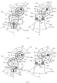
次いで、図24及び図25を参照して、開閉第1歯車451、開閉第2歯車452、回転第1歯車461及び回転第2歯車462の位置決め方法について説明する。なお、かかる位置決め方法の説明においては、図21から図23を適宜参照する。   Next, with reference to FIG. 24 and FIG. 25, a positioning method of the opening / closing first gear 451, the opening / closing second gear 452, the rotating first gear 461 and the rotating second gear 462 will be described. In the description of the positioning method, FIGS. 21 to 23 are referred to as appropriate.

図24及び図25は、開閉第1歯車451及び開閉第2歯車452と回転第1歯車461及び回転第2歯車462とを第1軸426及び第2軸427に組み付ける工程を時系列で説明する複合動作ユニット400の部分拡大正面図である。なお、図24(a)では、減速ギヤ425に減速歯車441が組み付けられた状態が、図24(b)では、図24(a)に図示される状態に対して更に第1軸426に開閉第1歯車451が組み付けられた状態が、図25(a)では、図24(b)に図示される状態に対して更に第2軸427に開閉第2歯車452及び回転第2歯車462が組み付けられた状態が、図25(b)では、図25(a)に図示される状態に対して更に第1軸426に回転第1歯車461が組み付けられた状態が、それぞれ図示される。   FIGS. 24 and 25 illustrate the steps of assembling the opening / closing first gear 451 and the opening / closing second gear 452 and the rotating first gear 461 and the rotating second gear 462 to the first shaft 426 and the second shaft 427 in time series. FIG. 4 is a partially enlarged front view of a combined operation unit 400. In FIG. 24A, the state in which the reduction gear 441 is assembled to the reduction gear 425 is opened and closed with respect to the first shaft 426 in FIG. 24B with respect to the state shown in FIG. In the state where the first gear 451 is assembled, in FIG. 25A, the opening / closing second gear 452 and the rotating second gear 462 are further assembled to the second shaft 427 with respect to the state illustrated in FIG. FIG. 25B shows the state where the rotation first gear 461 is further assembled to the first shaft 426 with respect to the state shown in FIG. 25A.

ここで、複合動作ユニット400は、上述したように、駆動モータ430の回転駆動力を減速歯車441を介して開閉第1歯車451及び開閉第2歯車452へ順に伝達することで、その開閉第2歯車452の回転によりスライドラック部材481を変位させ、動作部材491,492の開閉動作を行うと共に、駆動モータ430の回転駆動力を減速歯車441を介して回転第1歯車461及び回転第2歯車462へ順に伝達することで、その回転第2歯車462の回転により裏アーム体471及び表アーム体472を回転させ、動作部材491,492の回転動作を行う。   Here, as described above, the combined operation unit 400 transmits the rotation driving force of the drive motor 430 to the opening / closing first gear 451 and the opening / closing second gear 452 in order via the reduction gear 441, thereby opening and closing the second opening / closing gear. The slide rack member 481 is displaced by the rotation of the gear 452 to open and close the operation members 491 and 492, and the rotational driving force of the drive motor 430 is transmitted through the reduction gear 441 to the first rotary gear 461 and the second rotary gear 462. , The back arm body 471 and the front arm body 472 are rotated by the rotation of the rotation second gear 462, and the operation members 491 and 492 are rotated.

そのため、動作部材491,492の開閉動作および回転動作を適正に行う(即ち、部材どうしの干渉や移動範囲のずれの発生を回避する)ためには、開閉第1歯車451に対する開閉第2歯車452の回転位置(位相、歯合位置)、及び、回転第1歯車461に対する回転第2歯車462の回転位置が、それぞれ所定の回転位置に位置決めされた上で、これら各歯車451〜462が保持ケース420にそれぞれ組み付けられている必要がある。   Therefore, in order to properly perform the opening / closing operation and the rotating operation of the operating members 491, 492 (that is, avoiding the occurrence of interference between members and displacement of the moving range), the opening / closing second gear 452 with respect to the opening / closing first gear 451. The rotation position (phase, meshing position) of the rotation and the rotation position of the rotation second gear 462 with respect to the rotation first gear 461 are positioned at predetermined rotation positions, and the gears 451 to 462 are held by the holding case. 420 needs to be assembled to each.

しかしながら、従来の遊技機では、このように、一方の歯車に対する他方の歯車の回転位置(位相、歯合位置)を位置決めした上で、これら両歯車を組み付けるには、作業者が両歯車の回転位置を目視により調整して組み付ける必要があったため、作業が煩雑であり、作業効率が悪いばかりか、組み付け不良の発生する恐れがあった。   However, in conventional gaming machines, in order to assemble these gears after positioning the rotation position (phase, meshing position) of the other gear with respect to one gear, the operator must rotate both gears. Since it was necessary to adjust the position visually and assemble, the work was complicated, and the work efficiency was not only poor, but there was a risk of assembly failure.

これに対し、本実施形態では、開閉第1歯車451及び回転第1歯車461に対する開閉第2歯車452及び回転第2歯車462それぞれの相対的な回転位置(位相、歯合位置)と、これら各歯車451,452,461,462の裏ケース体421に対する取り付け位置(位相)を位置決めする位置決め構造を備え、この位置決め構造を利用することで、各歯車451〜462を保持ケース420に組み付ける際に、その作業性を向上させつつ、組み付け不良の発生を回避することが可能に構成される。   On the other hand, in the present embodiment, the relative rotational positions (phase, meshing position) of the open / close second gear 452 and the rotary second gear 462 with respect to the open / close first gear 451 and the rotary first gear 461, and the respective A positioning structure for positioning the mounting positions (phases) of the gears 451, 452, 461, 462 with respect to the back case body 421 is provided, and when the gears 451 to 462 are assembled to the holding case 420 by using this positioning structure, While improving the workability, it is possible to avoid the occurrence of assembly failure.

具体的には、まず、図24(a)に示すように、減速軸425に減速歯車441を組み付け、ピニオンギヤ431に歯合させる。上述したように、取り付けベース410の位置決め孔410a,410b(図21参照)には裏ケース体421の位置決め孔421a,421bがそれぞれ連通されているので、取り付けベース410の背面側から、位置決め孔410a,410bにそれぞれ冶具(図示せず)を挿通し、かかる冶具を位置決め孔421a,421bから裏ケース体421の正面側に突出させる。なお、冶具は、位置決め孔410a等の内径と同等または若干小さな外径を有する断面円形の円柱状体として形成される。   Specifically, first, as shown in FIG. 24A, the reduction gear 441 is assembled to the reduction shaft 425 and meshed with the pinion gear 431. As described above, since the positioning holes 421a and 421b of the back case body 421 are communicated with the positioning holes 410a and 410b (see FIG. 21) of the mounting base 410, respectively, the positioning holes 410a from the back side of the mounting base 410. 410b are inserted through jigs (not shown), and the jigs are projected from the positioning holes 421a and 421b to the front side of the back case body 421. The jig is formed as a cylindrical body having a circular cross section having an outer diameter equal to or slightly smaller than the inner diameter of the positioning hole 410a and the like.

次いで、裏ケース体421の位置決め孔421aから突出される冶具を、開閉第1歯車451の位置決め孔451eに挿通させつつ、開閉第1歯車451を第1軸426に組み付ける(軸支させる)。これにより、図24(b)に示すように、開閉第1歯車451を減速歯車441に歯合させると共に、開閉第1歯車451の裏ケース体421に対する取り付け位置(位相)を位置決めすることができる。   Next, the open / close first gear 451 is assembled (supported) to the first shaft 426 while the jig protruding from the positioning hole 421a of the back case body 421 is inserted into the positioning hole 451e of the open / close first gear 451. Accordingly, as shown in FIG. 24B, the opening / closing first gear 451 is engaged with the reduction gear 441, and the mounting position (phase) of the opening / closing first gear 451 with respect to the back case body 421 can be positioned. .

この裏ケース体421に対して位置決めされた状態(開閉第1歯車451の位置決め孔451eに冶具が挿通された状態)を維持しつつ、次いで、開閉第2歯車452及び回転第2歯車462を第2軸427に組み付ける(軸支させる)。   While maintaining the state of positioning relative to the back case body 421 (the state where the jig is inserted into the positioning hole 451e of the opening / closing first gear 451), the opening / closing second gear 452 and the rotating second gear 462 are then moved to the first position. It is assembled (supported) on the two shafts 427.

なお、開閉第2歯車452及び回転第2歯車462は、裏アーム体471及び表アーム体472と一体化された状態で作業される。即ち、開閉第2歯車452は、その挿通孔452が裏アーム体471の円筒状の部分が軸支され、回転第2歯車462は、その連結突部462dが表アーム体472の連結突部472eに締結固定された状態で、開閉第2歯車452及び回転第2歯車462が裏アーム体471と表アーム体472との対向間に介設される。また、裏ケース421の位置決め孔421bに挿通される冶具は、回転第2歯車462の位置決め孔462eに挿通可能となる高さ位置まで裏ケース421の表面から突出される。   The opening / closing second gear 452 and the rotating second gear 462 are operated in a state of being integrated with the back arm body 471 and the front arm body 472. That is, the opening / closing second gear 452 has the insertion hole 452 pivotally supported by the cylindrical portion of the back arm body 471, and the rotating second gear 462 has the connection protrusion 462d connected to the connection protrusion 472e of the front arm body 472. The second opening / closing gear 452 and the second rotating gear 462 are interposed between the back arm body 471 and the front arm body 472 facing each other. Further, the jig inserted through the positioning hole 421b of the back case 421 protrudes from the surface of the back case 421 to a height position where it can be inserted into the positioning hole 462e of the second rotating gear 462.

この場合、開閉第2歯車452及び回転第2歯車462の第2軸427への組み付けは、裏ケース体421の位置決め孔421bから突出される冶具を、裏アーム体471の位置決め孔471e、開閉第2歯車452の位置決め孔452e及び回転第2歯車462の位置決め孔462eに順に挿通させつつ、これら開閉第2歯車452及び回転第2歯車462を第2軸427に組み付ける(軸支させる)。これにより、図25(a)に示すように、開閉第2歯車452を開閉第1歯車451に歯合させ、開閉第1歯車451に対する開閉第2歯車452の回転位置(位相、歯合位置)を位置決めすることができると共に、開閉第2歯車452及び回転第2歯車462の裏ケース体421に対する取り付け位置(位相)を位置決めすることができる。   In this case, the opening / closing second gear 452 and the rotating second gear 462 are assembled to the second shaft 427 by using a jig protruding from the positioning hole 421b of the back case body 421, the positioning hole 471e of the back arm body 471, and the opening / closing first. The opening / closing second gear 452 and the rotating second gear 462 are assembled (supported) on the second shaft 427 while being sequentially inserted through the positioning hole 452e of the second gear 452 and the positioning hole 462e of the rotating second gear 462. Accordingly, as shown in FIG. 25A, the opening / closing second gear 452 is meshed with the opening / closing first gear 451, and the rotation position (phase, meshing position) of the opening / closing second gear 452 with respect to the opening / closing first gear 451. Can be positioned, and the attachment position (phase) of the opening / closing second gear 452 and the rotating second gear 462 with respect to the back case body 421 can be positioned.

この裏ケース体421に対して位置決めされた状態(少なくとも裏アーム体471の位置決め孔471eに冶具が挿通された状態)を維持しつつ、最後に、第1軸426に軸支されている開閉第1歯車451の連結突部451dを、回転第1歯車461の連結孔461dに挿通させつつ、回転第1歯車461を第1軸426に組み付ける(軸支させる)。これにより、図25(b)に示すように、回転第1歯車461を回転第2歯車462に歯合させると共に、回転第2歯車462の裏ケース体421に対する取り付け位置(位相)を位置決めすることができる。   Finally, while maintaining the state of positioning relative to the back case body 421 (at least the state where the jig is inserted into the positioning hole 471e of the back arm body 471), the opening / closing operation supported by the first shaft 426 is finally performed. The rotating first gear 461 is assembled (supported) on the first shaft 426 while the connecting protrusion 451d of the first gear 451 is inserted into the connecting hole 461d of the rotating first gear 461. Thus, as shown in FIG. 25B, the rotating first gear 461 is engaged with the rotating second gear 462, and the mounting position (phase) of the rotating second gear 462 with respect to the back case body 421 is positioned. Can do.

回転第1歯車461を第1軸426に取り付けた(軸支させた)後は、冶具を裏ケース体421の背面側から抜き取る。これにより、裏ケース体421(第1軸426及び第2軸427)への各歯車451〜462の組み付け(軸支)が完了される。   After the rotating first gear 461 is attached to (supported by) the first shaft 426, the jig is removed from the back side of the back case body 421. Thereby, the assembly (axial support) of the gears 451 to 462 to the back case body 421 (the first shaft 426 and the second shaft 427) is completed.

このように、本実施形態によれば、裏ケース体421の第1軸426及び第2軸427の側方に平行に冶具が立設され、この冶具を位置決め孔451e等に挿通させつつ各歯車451〜462を順に第1軸426及び第2軸427等に組み付ける(軸支させる)ことで、裏ケース体421を基準として、各歯車451〜462の回転位置(位相、歯合位置)を位置決めすることができる。即ち、第1軸426や第2軸427を各歯車451〜462へ挿通させるのと同時に冶具の挿通も行うことができるので、組み付け作業と位置決め作業とを同時に実行可能として、作業性の向上を図ることができる。   As described above, according to the present embodiment, the jigs are erected in parallel to the sides of the first shaft 426 and the second shaft 427 of the back case body 421, and the gears are inserted through the positioning holes 451e and the like. By assembling (shaft-supporting) 451 to 462 to the first shaft 426 and the second shaft 427 in order, the rotational positions (phases and meshing positions) of the gears 451 to 462 are positioned with the back case body 421 as a reference. can do. That is, since the jig can be inserted at the same time as the first shaft 426 and the second shaft 427 are inserted into the gears 451 to 462, the assembling work and the positioning work can be performed at the same time, thereby improving the workability. Can be planned.

特に、開閉第2歯車452及び回転第2歯車462については、開閉第2歯車452の位置決め孔452eが貫通孔として形成されるので、これら開閉第2歯車452及び回転第2歯車462の第2軸427への組み付け(軸支)を同時に行うことができる。特に、本実施形態では、裏アーム体471の位置決め孔471eが貫通孔として形成されるので、開閉第2歯車452及び回転第2歯車462を裏アーム体471及び表アーム体472と一体化した状態で第2軸427へ組み付ける(軸支させる)ことができる。よって、各アーム体471,472と各歯車452,462をそれぞれ位置決めしつつ組み付ける必要がなく、一度の組み付け作業で位置決め作業も完了でき、その作業性の向上を図ることができる。   In particular, with respect to the opening / closing second gear 452 and the rotating second gear 462, the positioning hole 452e of the opening / closing second gear 452 is formed as a through hole, so that the second shaft of the opening / closing second gear 452 and the rotating second gear 462 is formed. Assembly to 427 (shaft support) can be performed simultaneously. In particular, in the present embodiment, since the positioning hole 471e of the back arm body 471 is formed as a through hole, the open / close second gear 452 and the rotating second gear 462 are integrated with the back arm body 471 and the front arm body 472. Can be assembled (supported) on the second shaft 427. Accordingly, it is not necessary to position and assemble the arm bodies 471 and 472 and the gears 452 and 462, and the positioning work can be completed by a single assembling work, and the workability can be improved.

また、この場合には、開閉第2歯車452及び回転第2歯車462と裏アーム体471及び表アーム体472とに対し、それぞれに専用の冶具を準備する必要がなく、共通の冶具を使用することができるので、その分、製品コストの削減を図ることができる。更に、
開閉第2歯車452及び回転第2歯車462は互いに独立して相対回転可能である必要があるところ、冶具を裏ケース体421の背面側へ脱抜すれば開閉第2歯車452及び回転第2歯車462を独立して回転可能とすることができる。よって、開閉第2歯車452及び回転第2歯車462のそれぞれに個別に回転軸を設ける必要がなく、これら開閉第2歯車452及び回転第2歯車462を共通の回転軸(第2軸427)に軸支させることができるので、かかる点からも製品コストの削減を図ることができる。
Further, in this case, it is not necessary to prepare dedicated jigs for the open / close second gear 452 and the rotating second gear 462, the back arm body 471, and the front arm body 472, and a common jig is used. Therefore, the product cost can be reduced accordingly. Furthermore,
The opening / closing second gear 452 and the rotating second gear 462 need to be able to rotate relative to each other independently. However, if the jig is removed to the back side of the back case body 421, the opening / closing second gear 452 and the rotating second gear are required. 462 can be independently rotatable. Therefore, there is no need to provide a separate rotation shaft for each of the open / close second gear 452 and the rotary second gear 462, and the open / close second gear 452 and the rotary second gear 462 are used as a common rotary shaft (second shaft 427). Since it can be pivotally supported, the product cost can be reduced from this point.

一方で、開閉第1歯車451及び回転第1歯車461は、互いに連結され同位相で一体的に回転可能である必要がある。この場合、開閉第1歯車451及び回転第1歯車461は、開閉第1歯車451の一対の連結突部451dを、回転第1歯車461の一対の連結孔461dに挿通(内嵌)させることで、それら両歯車451,461どうしを連結して、その回転位置(位相)の位置決めと、同位相での一体的な回転とを同時に可能とする。即ち、両歯車451,461の回転位置(位相)の位置決めと、一体的な回転のための両歯車451,461どうしの連結とを連結突部451d及び連通孔461dに兼用させることができ、回転位置を位置決めする(即ち、冶具を挿通する)ための貫通孔と、一体的な回転のための連結構造とのそれぞれを個別に設ける必要がない。これにより、両歯車451,461の形状を簡素化して、製造上の歩留まりの向上を図ることができる。また、回転第1歯車461(本体部461a)に貫通して形成される貫通孔の形成数を抑制できるので、その分、剛性を確保して、耐久性の向上を図ることができる。   On the other hand, the opening / closing first gear 451 and the rotating first gear 461 need to be connected to each other and integrally rotatable in the same phase. In this case, the opening / closing first gear 451 and the rotating first gear 461 are inserted (internally fitted) through the pair of connecting projections 451d of the opening / closing first gear 451 into the pair of connecting holes 461d of the rotating first gear 461. These gears 451 and 461 are connected to each other so that positioning of the rotational position (phase) and integral rotation in the same phase can be performed simultaneously. In other words, the positioning of the rotational positions (phases) of the two gears 451 and 461 and the connection of the two gears 451 and 461 for integral rotation can be shared by the connection protrusion 451d and the communication hole 461d. There is no need to individually provide a through hole for positioning the position (that is, through the jig) and a connection structure for integral rotation. Thereby, the shape of both the gears 451 and 461 can be simplified, and the production yield can be improved. Further, since the number of through holes formed so as to penetrate through the first rotating gear 461 (main body portion 461a) can be suppressed, rigidity can be ensured correspondingly and durability can be improved.

特に、回転第1歯車461には、一対の連通孔461dが貫通孔として形成されるが、これら一対の連通孔461dには、開閉第1歯車451の一対の連結突部451dが挿通(内嵌)されるので、その嵌め合い構造により、回転第1歯車461(本体部461a)の剛性の向上を図ることができる。   In particular, the rotation first gear 461 is formed with a pair of communication holes 461d as through holes, and the pair of communication holes 461d are inserted (internally fitted) into the pair of connection projections 451d of the opening / closing first gear 451. Therefore, the rigidity of the rotating first gear 461 (main body 461a) can be improved by the fitting structure.

ここで、本実施形態の位置決め構造によれば、上述の通り、裏ケース体421の正面から冶具を突出させ、この冶具を利用して回転位置の位置決めを行いつつ、各歯車451〜462を順に第1軸426及び第2軸427等に組み付ける(軸支させる)ところ、全ての歯車451〜462の組み付けが完了した後に、裏ケース体421の背面から冶具を脱抜することができる。即ち、各歯車451〜462をそれぞれ組み付ける際には、各歯車451〜462のうちの既に組み付けられている歯車451〜462の位置決め孔451e〜462eに冶具が挿通された状態を維持しつつ、各歯車451〜462のうちの残りの歯車451〜461の組み付け作業を行うことができる。これにより、既に組み付けられている歯車451〜461を作業者が作業中に不用意に回転させてしまうことを回避できるので、作業性の向上を図ることができると共に、位置決めされた回転位置の信頼性の向上を図ることができる。   Here, according to the positioning structure of the present embodiment, as described above, a jig is protruded from the front surface of the back case body 421 and the gears 451 to 462 are sequentially arranged while positioning the rotational position using the jig. When assembled to the first shaft 426 and the second shaft 427 (supported), the jig can be removed from the back surface of the back case body 421 after the assembly of all the gears 451 to 462 is completed. That is, when assembling each gear 451-462, while maintaining the state where the jig is inserted into the positioning holes 451e-462e of the already-assembled gears 451-462 of the gears 451-462, The remaining gears 451 to 461 among the gears 451 to 462 can be assembled. As a result, it is possible to prevent the operator from inadvertently rotating the already assembled gears 451 to 461 during work, so that workability can be improved and the reliability of the positioned rotational position can be improved. It is possible to improve the performance.

なお、本実施形態では、開閉第1歯車451と回転第1歯車461とが第1軸426に、開閉第2歯車452と回転第2歯車462とが第2軸427に、それぞれ同軸に配設されるので、開閉第1歯車451及び開閉第2歯車452との間におけるバックラッシュと、回転第1歯車461及び回転第2歯車462との間におけるバックラッシュとを同じ方向で発生させることができる。これにより、後述するように、動作部材491,492の開閉動作および回転動作を行う際には(図27から図30参照)、その演出タイミングにずれが生じることを抑制できる。   In the present embodiment, the opening / closing first gear 451 and the rotating first gear 461 are coaxially disposed on the first shaft 426, and the opening / closing second gear 452 and the rotating second gear 462 are coaxially disposed on the second shaft 427, respectively. Therefore, the backlash between the opening / closing first gear 451 and the opening / closing second gear 452 and the backlash between the rotating first gear 461 and the rotating second gear 462 can be generated in the same direction. . As a result, as will be described later, when the opening / closing operation and the rotation operation of the operation members 491 and 492 are performed (see FIGS. 27 to 30), it is possible to suppress the production timing from being shifted.

次いで、図26を参照して、動作部材491,492の開閉動作について説明する。図26(a)から図26(c)は、裏アーム体471に対する開閉第2歯車452及びスライドラック部材481の相対的な変位状態を説明するための複合動作ユニット400の分解正面図であり、動作部材491,492及び表アーム体472が取り外された状態が図示される。なお、図26(a)は、図26(b)に対して、開閉第2歯車452が反時計回り(左回り)に、図26(c)は、図26(b)に対して、開閉第2歯車452が時計回り(右回り)に、それぞれ回転された状態に対応する。   Next, the opening / closing operation of the operation members 491 and 492 will be described with reference to FIG. 26 (a) to 26 (c) are exploded front views of the combined operation unit 400 for explaining the relative displacement state of the open / close second gear 452 and the slide rack member 481 with respect to the back arm body 471. A state in which the operation members 491 and 492 and the front arm body 472 are removed is illustrated. 26 (a) shows the opening / closing second gear 452 counterclockwise (counterclockwise) with respect to FIG. 26 (b), and FIG. 26 (c) shows opening / closing with respect to FIG. 26 (b). This corresponds to the state in which the second gear 452 is rotated clockwise (clockwise).

図26(a)から図26(c)に示すように、開閉第2歯車452の挿通孔452bには、裏ケース体271の円筒状の部位(図21及び図22参照)が挿通されており、これにより、開閉第2歯車452は、裏ケース271に対して第2軸427を中心として相対的に回転可能とされる。   As shown in FIGS. 26 (a) to 26 (c), the cylindrical portion (see FIGS. 21 and 22) of the back case body 271 is inserted into the insertion hole 452b of the open / close second gear 452. Thus, the opening / closing second gear 452 is rotatable relative to the back case 271 about the second shaft 427.

一対の第1ピニオン脚部材482は、上述したように、互いの間に架設された付勢ばね484(図22参照)の付勢力により、互いが近接する方向へ付勢された状態で、裏アーム体471の軸部471cに軸支孔482bが回転可能に軸支される。即ち、付勢ばね484の付勢力を受けることで、一対の第1ピニオン脚部材482のうちの図26(b)右側に位置する第1ピニオン脚部材482は軸部471cを中心に反時計回り(左回り)に回転される一方、図26(b)左側に位置する第1ピニオン脚部材482は軸部471cを中心に時計回り(右回り)に回転される。よって、スライドラック部材481は、一対の第1ピニオン脚部材482の回転を介して作用する付勢ばね484の付勢力により、両アーム体471,472のガイド凹部471d,472d(図21及び図22参照)に沿って、下方(開閉第2歯車452から離間する方向、図26(b)下側)にスライド変位される。   As described above, the pair of first pinion leg members 482 are urged toward each other by the urging force of the urging spring 484 (see FIG. 22) installed between them. A shaft support hole 482b is rotatably supported by the shaft portion 471c of the arm body 471. That is, by receiving the biasing force of the biasing spring 484, the first pinion leg member 482 located on the right side in FIG. 26B of the pair of first pinion leg members 482 rotates counterclockwise around the shaft portion 471c. While being rotated (counterclockwise), the first pinion leg member 482 located on the left side of FIG. 26 (b) is rotated clockwise (clockwise) about the shaft portion 471c. Therefore, the slide rack member 481 has the guide recesses 471d and 472d (FIGS. 21 and 22) of the both arm bodies 471 and 472 by the biasing force of the biasing spring 484 acting through the rotation of the pair of first pinion leg members 482. (See FIG. 26B, the direction away from the open / close second gear 452).

よって、図26(b)に示すように、付勢ばね484の付勢力に抗して開閉第2歯車452が回転されていない状態では、開閉第2歯車452は、その連結突部452dがスライドラック部材481により下方(図26(b)下側)へ引き寄せられ、スライド変位の方向(図26(b)上下方向)における連結溝481c及び第2軸427の間の距離が距離L1とされる。また、一対の第1ピニオン脚部材482は、それらの連結孔482dの間の間隔が間隔W1とされる。   Therefore, as shown in FIG. 26B, in the state where the opening / closing second gear 452 is not rotated against the biasing force of the biasing spring 484, the connecting protrusion 452d of the opening / closing second gear 452 slides. The distance between the connection groove 481c and the second shaft 427 in the direction of slide displacement (vertical direction in FIG. 26B) is drawn to the distance L1 by the rack member 481 (lower side in FIG. 26B). . Further, in the pair of first pinion leg members 482, the interval between the connecting holes 482d is the interval W1.

図26(b)に示す状態から、例えば、開閉第2歯車452が裏アーム体471に対して第2軸427を中心に反時計回り(左回り)に回転されると、連結突部452dがスライドラック部材481の連結溝481c内を摺動することで、かかる連結突部452dの移動がスライドラック部材481を付勢ばね484の付勢力に抗しつつ上方(図26(a)上側)へスライド変位させる。   From the state shown in FIG. 26B, for example, when the open / close second gear 452 is rotated counterclockwise (counterclockwise) about the second shaft 427 with respect to the back arm body 471, the connecting protrusion 452d is By sliding in the connecting groove 481c of the slide rack member 481, the movement of the connecting protrusion 452d moves upward (upward in FIG. 26A) against the biasing force of the biasing spring 484. Displace the slide.

即ち、図26(a)に示すように、開閉第2歯車452が所定の回転位置まで回転されると、スライド変位の方向(図26(a)上下方向)における連結溝481c及び第2軸427の間の距離が距離L2に短縮され(L2<L1)、その距離L1,L2の差の分だけ、スライドラック部材481が上方へスライド変位される。このスライドラック部材481の上方へのスライド変位に伴い、一対の第1ピニオン脚部材482は、互いが離間する方向へ回転され、それらの連結孔482dの間の間隔が拡大されて間隔W2とされる(W1<W2)。   That is, as shown in FIG. 26A, when the open / close second gear 452 is rotated to a predetermined rotational position, the connecting groove 481c and the second shaft 427 in the slide displacement direction (vertical direction in FIG. 26A). Is reduced to a distance L2 (L2 <L1), and the slide rack member 481 is slid upward by the difference between the distances L1 and L2. As the slide rack member 481 slides upward, the pair of first pinion leg members 482 are rotated in a direction away from each other, and the interval between the connecting holes 482d is enlarged to be the interval W2. (W1 <W2).

なお、一対の第2ピニオン脚部材483についても、一対の第1ピニオン脚部材482と同様であり、図26(b)に示す状態では、互いに近接する姿勢(それらの連結孔483dの間の間隔が最小となる状態)に配置され、図26(a)に示す状態では、スライドラック部材481の上方へのスライド変位に伴い、互いに離間する姿勢(それらの連結孔483dの間の間隔が最大となる状態)に配置される。   The pair of second pinion leg members 483 is the same as the pair of first pinion leg members 482, and in the state shown in FIG. 26B, the postures close to each other (the distance between the connecting holes 483d). 26 (a), and in the state shown in FIG. 26 (a), as the slide rack member 481 slides upward, the postures are separated from each other (the interval between the connecting holes 483d is the maximum). Arranged).

図26(a)に示す状態から、開閉第2歯車452が裏アーム体471に対して第2軸427を中心に時計回り(右回り)に回転されると、図26(b)に示す状態に復帰される。この図26(b)に示す状態から、開閉第2歯車452が裏アーム体471に対して第2軸427を中心に時計回り(右回り)に更に回転されると、連結突部452dがスライドラック部材481の連結溝481c内を摺動することで、かかる連結突部452dの移動がスライドラック部材481を付勢ばね484の付勢力に抗しつつ上方(図26(c)上側)へスライド変位させる。 これにより、図26(a)に示す場合と同様に、開閉第2歯車452が所定の回転位置まで回転されると、図26(c)に示すように、スライド変位の方向(図26(c)上下方向)における連結溝481c及び第2軸427の間の距離が距離L2に短縮され(L2<L1)、その距離L1,L2の差の分だけ、スライドラック部材481が上方へスライド変位される。このスライドラック部材481の上方へのスライド変位に伴い、一対の第1ピニオン脚部材482(及び第2ピニオン脚部材483)は、互いが離間する方向へ回転され、それらの連結孔482dの間の間隔が拡大されて間隔W2とされる(W1<W2)。   When the open / close second gear 452 is rotated clockwise (clockwise) about the second shaft 427 with respect to the back arm body 471 from the state shown in FIG. 26A, the state shown in FIG. Returned to When the open / close second gear 452 is further rotated clockwise (clockwise) about the second shaft 427 with respect to the back arm body 471 from the state shown in FIG. 26B, the connecting projection 452d slides. By sliding in the connecting groove 481c of the rack member 481, the movement of the connecting protrusion 452d slides upward (upward in FIG. 26C) against the biasing force of the biasing spring 484. Displace. Thus, as in the case shown in FIG. 26 (a), when the open / close second gear 452 is rotated to a predetermined rotational position, as shown in FIG. 26 (c), the direction of the slide displacement (FIG. 26 (c) ) The distance between the connecting groove 481c and the second shaft 427 in the vertical direction) is shortened to the distance L2 (L2 <L1), and the slide rack member 481 is slid upward by the difference between the distances L1 and L2. The As the slide rack member 481 slides upward, the pair of first pinion leg members 482 (and the second pinion leg members 483) are rotated in a direction away from each other, and between the connecting holes 482d. The interval is enlarged to be the interval W2 (W1 <W2).

次いで、図27から図30を参照して、複合動作ユニット400による動作部材491,492の回転動作および開閉動作について説明する。   Next, with reference to FIGS. 27 to 30, the rotation operation and the opening / closing operation of the operation members 491 and 492 by the composite operation unit 400 will be described.

図27(a)から図27(d)は、動作部材491,492の開閉動作および回転動作を時系列で図示した複合動作ユニット400の正面図である。なお、図27(a)では、動作部材491,492が上昇位置Uに配置され且つ開放された状態が、図27(b)では、動作部材491,492が上昇位置Uに配置され且つ閉鎖された状態が、図27(c)では、動作部材491,492が下降位置Dに配置され且つ閉鎖された状態が、図27(d)では、動作部材491,492が下降位置Dに配置され且つ開放された状態が、それぞれ図示される。   27 (a) to 27 (d) are front views of the composite operation unit 400 illustrating the opening / closing operation and the rotation operation of the operation members 491 and 492 in time series. In FIG. 27A, the operating members 491 and 492 are arranged at the raised position U and opened, and in FIG. 27B, the operating members 491 and 492 are arranged at the raised position U and closed. In FIG. 27C, the operating members 491 and 492 are disposed at the lowered position D and closed, and in FIG. 27D, the operating members 491 and 492 are disposed at the lowered position D and Each opened state is illustrated.

図28から図30は、開閉第1歯車451と開閉第2歯車452との歯合状態および回転第1歯車461と回転第2歯車462との歯合状態をそれぞれ模式的に図示する複合動作ユニット400の正面模式図である。なお、図28(a)は図27(a)の状態に、図28(b)及び図29(a)は図27(b)の状態に、図29(b)は図27(b)及び図27(c)の間の遷移状態に、図29(c)及び図30(a)は図27(c)の状態に、図30(b)は図27(d)の状態に、それぞれ対応する。また、図28(b)及び図29(a)と図29(c)及び図30(a)とには、それぞれ同一の状態が図示される。   28 to 30 are composite operation units schematically showing the meshing state of the first open / close gear 451 and the second gear 452 and the meshed state of the first rotating gear 461 and the second rotating gear 462, respectively. 400 is a schematic front view of 400. FIG. 28A shows the state shown in FIG. 27A, FIGS. 28B and 29A show the state shown in FIG. 27B, and FIG. 29B shows the state shown in FIGS. FIG. 29 (c) and FIG. 30 (a) correspond to the state of FIG. 27 (c), and FIG. 30 (b) corresponds to the state of FIG. 27 (d), respectively. To do. FIGS. 28 (b) and 29 (a) and FIGS. 29 (c) and 30 (a) show the same state.

ここで、図28から図30では、裏アーム体471及び表アーム体472が二点鎖線を用いて模式的に図示される。また、図28から図30では、開閉第1歯車451の一対の連結突部451dのうちの一方の連結突部451dと、回転第1歯車461の一対の連結孔461dのうちの一方の連結孔461dとにそれぞれハッチングを付して図示し、このハッチングを付した連結突部451d及び連結孔461dを後述する回転角度θ0〜θ4の基準として説明する。即ち、開閉第1歯車451及び回転第1歯車462は、ハッチングを付した連結突部451dがハッチングを付した連結孔461dに挿通(内嵌)され、これらが同じ回転位置に配置される。   Here, in FIG. 28 to FIG. 30, the back arm body 471 and the front arm body 472 are schematically illustrated using a two-dot chain line. Further, in FIGS. 28 to 30, one connection protrusion 451 d of the pair of connection protrusions 451 d of the opening / closing first gear 451 and one connection hole of the pair of connection holes 461 d of the rotating first gear 461. 461d is shown with hatching, and the hatched connecting projection 451d and connecting hole 461d will be described as a reference for rotation angles θ0 to θ4 described later. That is, the opening / closing first gear 451 and the rotating first gear 462 are inserted (internally fitted) into the hatched connecting hole 461d by the hatched connecting projection 451d, and these are arranged at the same rotational position.

また、図28から図30では、動作部材491,492が上昇位置Uに配置され且つ開放された状態(図27(a)に示す状態)における開閉第1歯車451及び回転第1歯車461の回転位置を回転角度θ0と、動作部材491,492が上昇位置Uに配置され且つ閉鎖された状態(図27(b)に示す状態)における開閉第1歯車451及び回転第1歯車461の回転位置を回転角度θ1と、動作部材491,492が上昇位置U及び下降位置Dの間に配置され且つ閉鎖された状態(図27(b)及び図27(c)の間の状態)における開閉第1歯車451及び回転第1歯車461の回転位置を回転角度θ2と、動作部材491,492が下降位置Dに配置され且つ閉鎖された状態(図27(c)に示す状態)における開閉第1歯車451及び回転第1歯車461の回転位置を回転角度θ3と、動作部材491,492が下降位置Dに配置され且つ開放された状態(図27(d)に示す状態)における開閉第1歯車451及び回転第1歯車461の回転位置を回転角度θ4と、それぞれ定義する。   Also, in FIGS. 28 to 30, the rotation of the first opening / closing gear 451 and the rotation first gear 461 when the operating members 491 and 492 are disposed at the raised position U and opened (the state shown in FIG. 27A). The rotational angle θ0 is the rotational position of the opening / closing first gear 451 and the rotational first gear 461 when the operating members 491 and 492 are disposed at the raised position U and are closed (the state shown in FIG. 27B). The first opening / closing gear in the state where the rotation angle θ1 and the operation members 491 and 492 are disposed between the raised position U and the lowered position D and are closed (the state between FIGS. 27B and 27C). 451 and the rotating first gear 461 are rotated at the rotational angle θ2, and the first opening / closing gear 451 in a state where the operating members 491 and 492 are disposed at the lowered position D and closed (the state shown in FIG. 27C). The rotation position of the first rotation gear 461 is the rotation angle θ3, the first opening / closing gear 451 and the rotation in the state where the operation members 491 and 492 are disposed at the lowered position D and opened (the state shown in FIG. 27D). The rotational position of the first gear 461 is defined as a rotational angle θ4.

図27(a)及び図28(a)に示すように、開閉第1歯車451及び回転第1歯車461の回転位置が回転角度θ0にある場合には、動作部材491,492が上昇位置Uに配置され且つ開放された状態とされる。即ち、開閉第2歯車452が裏アーム体471及び表アーム体472に対して第2軸427を中心に所定の回転位置まで時計回り(右回り)に回転され、連結溝481c及び第2軸427の間の距離が距離L2に短縮されることで、スライドラック部材481が上方(第2軸427に近接する方向)へスライド変位された状態(図26(c)に示す状態)とされる。   As shown in FIGS. 27A and 28A, when the rotation positions of the first opening / closing gear 451 and the rotation first gear 461 are at the rotation angle θ0, the operation members 491 and 492 are at the raised position U. Arranged and opened. That is, the opening / closing second gear 452 is rotated clockwise (clockwise) to the predetermined rotation position around the second shaft 427 with respect to the back arm body 471 and the front arm body 472, and the connection groove 481c and the second shaft 427 are rotated. As the distance between the two is shortened to the distance L2, the slide rack member 481 is slid and displaced upward (in the direction approaching the second shaft 427) (the state shown in FIG. 26C).

この場合、回転第1歯車461及び回転第2歯車462は、回転第1歯車461の本体部461aにおける円筒面461a1に、回転第2歯車462の本体部462aにおける非形成面462a1が当接される。上述したように、回転第1歯車461(本体部461a)の円筒面461a1は、第1軸426を中心とする円筒面として形成されると共に、回転第2歯車462(本体部462a)の非形成面462a1は、第2軸427挿通孔462b側へ向けて凹む(即ち、曲率中心を第1軸426側に有する)湾曲面であって回転第1歯車461の円筒面461a1と同一の曲率または若干小さな曲率(即ち、若干大きな半径)の湾曲面として形成される。   In this case, the rotation first gear 461 and the rotation second gear 462 are in contact with the cylindrical surface 461a1 of the main body 461a of the rotation first gear 461 and the non-forming surface 462a1 of the main body 462a of the rotation second gear 462. . As described above, the cylindrical surface 461a1 of the rotating first gear 461 (main body portion 461a) is formed as a cylindrical surface centered on the first shaft 426, and the rotating second gear 462 (main body portion 462a) is not formed. The surface 462a1 is a curved surface that is recessed toward the second shaft 427 insertion hole 462b side (that is, has a center of curvature on the first shaft 426 side), and has the same curvature as the cylindrical surface 461a1 of the rotating first gear 461 or slightly. It is formed as a curved surface with a small curvature (ie a slightly larger radius).

よって、これら円筒面461a1と非形成面462a1との当接により、回転第2歯車462(即ち、その回転第2歯車462に固定される裏アーム体471及び表アーム体472)の第2軸427を中心とする回転が不能とされる。即ち、円筒面461a1及び非形成面462a1を、第2軸427を中心として回転第2歯車462が回転されることを規制(即ち、動作部材491,492を上昇位置Uに保持)するストッパ手段として機能させることができる。   Therefore, the second shaft 427 of the rotating second gear 462 (that is, the back arm body 471 and the front arm body 472 fixed to the rotating second gear 462) is brought into contact with the cylindrical surface 461a1 and the non-forming surface 462a1. It is impossible to rotate around the center. That is, the cylindrical surface 461a1 and the non-forming surface 462a1 serve as stopper means for restricting the rotation of the rotating second gear 462 about the second shaft 427 (that is, holding the operation members 491 and 492 at the raised position U). Can function.

ここで、従来の遊技機において、回転可能に配設される動作部材と、その動作部材に回転駆動力を付与する駆動モータとを備え、駆動モータの回動駆動力により動作部材を所定の回転範囲で回転させるものがある。この場合、例えば、動作部材の回転範囲の終端が上昇位置とされ、その回転範囲の終端に配置された動作部材に重力が作用される場合には、動作部材が重力の作用により回転(下降)しないようにする必要がある。しかしながら、従来の遊技機では、駆動モータの駆動力を重力(動作部材の重量)に対抗させることで、動作部材の回転(下降)を規制する(即ち、動作部材を回転範囲の終端に保持する)構造であるため、動作部材の保持に必要な消費エネルギーが嵩んでいた。   Here, a conventional gaming machine includes an operation member that is rotatably arranged, and a drive motor that applies a rotational drive force to the operation member, and the operation member is rotated by a predetermined amount by the rotational drive force of the drive motor. There is something to rotate in the range. In this case, for example, when the end of the rotation range of the operation member is set to the ascending position and gravity is applied to the operation member disposed at the end of the rotation range, the operation member is rotated (lowered) by the action of gravity. It is necessary not to do. However, in the conventional gaming machine, the rotation (lowering) of the operation member is regulated by causing the driving force of the drive motor to oppose gravity (the weight of the operation member) (that is, the operation member is held at the end of the rotation range). ) Because of the structure, the energy consumption required for holding the operating member was increased.

これに対し、本実施形態によれば、動作部材491,492が回転範囲の終端(上昇位置U)に配置されると、回転第1歯車461(本体部461a)の円筒面461a1と回転第2歯車462(本体部462a)の非形成面462a1とが当接されることで、動作部材491,492の回転動作(回転第2歯車462の回転動)を規制できる。即ち、本実施形態では、上述の通り、動作部材491,492が回転範囲の終端(上昇位置U)に配置されると、動作部材491,492と駆動モータ430とが切り離されるため、駆動モータの回転駆動力を利用して動作部材491,492を上昇位置Uに保持不能となるところ、円筒面461a1及び非形成面462a1の当接を利用して、動作部材491,492を上昇位置Uに機械的に保持できる。その結果、動作部材491,492の保持に必要な消費エネルギーを抑制できる。   On the other hand, according to the present embodiment, when the operation members 491 and 492 are arranged at the end of the rotation range (upward position U), the rotation first gear 461 (main body portion 461a) of the cylindrical surface 461a1 and the rotation second When the non-formation surface 462a1 of the gear 462 (main body portion 462a) is brought into contact, the rotation operation of the operation members 491 and 492 (the rotation of the rotation second gear 462) can be restricted. That is, in the present embodiment, as described above, when the operation members 491 and 492 are disposed at the end of the rotation range (upward position U), the operation members 491 and 492 and the drive motor 430 are separated from each other. When the operating members 491 and 492 cannot be held at the raised position U by using the rotational driving force, the operating members 491 and 492 are moved to the raised position U by utilizing the contact of the cylindrical surface 461a1 and the non-forming surface 462a1. Can be retained. As a result, energy consumption required for holding the operation members 491 and 492 can be suppressed.

この場合、回転第1歯車461(本体部461a)の円筒面461a1と回転第2歯車462(本体部462a)の非形成面462a1とは、互いが当接された場合(即ち、動作部材491,492が上昇位置U(及び、後述する下降位置D)に配置された場合)に、回転第2歯車462の第2軸427を中心とする両方向(右回り及び左回り)への回転を規制可能な形状に形成されるので、回転第2歯車462の第2軸427を中心とする回転を一方向のみ(即ち、動作部材491,492が重力の作用により下降位置Dへ向けて下降される方向のみ)で規制可能な形状に形成される場合と比較して、移動範囲の終端(上昇位置U(及び、後述する下降位置D))に到達した際の動作部材491,492の振動を収束させ、移動範囲の終端に動作部材491,492を速やかに位置決めできる。更に、動作部材491,492をその移動範囲の終端に安定した状態で保持できるので、上昇位置U(及び、後述する下降位置D)において、停止状態にあるべき動作部材491,492が外力(例えば、遊技者が遊技機を叩く又は揺らすことで発生する外力)により振動や位置ずれすることを抑制できる。   In this case, the cylindrical surface 461a1 of the rotating first gear 461 (main body portion 461a) and the non-forming surface 462a1 of the rotating second gear 462 (main body portion 462a) are in contact with each other (that is, the operating member 491, Rotation of the rotating second gear 462 in both directions (clockwise and counterclockwise) about the second shaft 427 can be restricted when the position 492 is arranged at the raised position U (and a lowered position D described later). Therefore, the rotation of the rotating second gear 462 around the second shaft 427 is performed only in one direction (that is, the direction in which the operating members 491 and 492 are lowered toward the lowered position D by the action of gravity). As compared with the case where the shape is formed in a shape that can be restricted by the above-described configuration, the vibrations of the operating members 491 and 492 when the terminal reaches the end of the movement range (upward position U (and downward position D described later)) are converged. , End of travel range The operation member 491, 492 can be positioned quickly. Furthermore, since the operation members 491 and 492 can be stably held at the end of the movement range, the operation members 491 and 492 that should be in the stop state at the ascending position U (and the descending position D described later) Further, it is possible to suppress vibrations and displacement due to an external force generated by the player hitting or shaking the gaming machine.

特に、本実施形態では、回転第2歯車462(本体部462a)の非形成面462a1は、回転第1歯車461(本体部461a)の円筒面461a1に当接された場合(即ち、動作部材491,492が上昇位置U(及び、後述する下降位置D)に配置された場合)に、回転第1歯車461の回転軸(第1軸426)を中心として円弧状に湾曲する形状であって、回転第1歯車461の円筒面461a1と同径または若干大きな径の円弧状に湾曲して形成される。   In particular, in the present embodiment, the non-formed surface 462a1 of the rotating second gear 462 (main body portion 462a) is in contact with the cylindrical surface 461a1 of the rotating first gear 461 (main body portion 461a) (that is, the operating member 491). , 492 are arranged in a raised position U (and a lowered position D, which will be described later), and are curved in an arc shape around the rotation shaft (first shaft 426) of the rotation first gear 461, The first rotating gear 461 is formed to be curved in an arc shape having the same diameter or slightly larger diameter than the cylindrical surface 461a1 of the rotating first gear 461.

これにより、回転第2歯車462の非形成面462a1を、回転第1歯車461の円筒面461a1に滑らかに当接させることができると共に、両者を面接触で当接させやすくできる。その結果、円筒面461a1及び非形成面462a1を滑らかに当接させ、動作部材491,492がその移動範囲の終端(上昇位置U(及び、後述する下降位置D))に到達して停止される際の衝撃を緩やにできると共に、円筒面461a1及び非形成面462a1の接触圧力を小さくして、回転第1歯車461及び回転第2歯車462の耐久性の向上を図ることができる。   Accordingly, the non-formed surface 462a1 of the rotating second gear 462 can be smoothly brought into contact with the cylindrical surface 461a1 of the rotating first gear 461, and both can be easily brought into contact with each other by surface contact. As a result, the cylindrical surface 461a1 and the non-forming surface 462a1 are smoothly brought into contact with each other, and the operation members 491 and 492 reach the end of the moving range (upward position U (and downward position D described later)) and are stopped. The impact at the time can be reduced, and the contact pressure between the cylindrical surface 461a1 and the non-formed surface 462a1 can be reduced, and the durability of the rotating first gear 461 and the rotating second gear 462 can be improved.

ここで、回転第2歯車462は、上述したように、表アーム体472の剛性を利用して(即ち、表アーム体472と一体となることで)、その剛性が高められている。よって、回転第2歯車462の厚肉化や高剛性素材を採用する必要がなく、これにより、回転第2歯車462の軽量化および低コスト化を図りつつ、回転第2歯車462の耐久性の向上が図られている。   Here, as described above, the rotation second gear 462 is enhanced in rigidity by utilizing the rigidity of the front arm body 472 (that is, by being integrated with the front arm body 472). Therefore, there is no need to increase the thickness of the rotating second gear 462 or to use a highly rigid material, thereby reducing the weight and cost of the rotating second gear 462 and improving the durability of the rotating second gear 462. Improvements are being made.

特に、回転第2歯車462は、上述したように、その連結突部462dが非形成面462a1の背面側(即ち、非形成面462a1を挟んで回転第1歯車461の円筒面461a1と対向する位置)に配設されるので、上昇位置U(及び、後述する下降位置D)において、回転第2歯車462の非形成面462a1を回転第1歯車461の円筒面461a1に当接させる際にその回転第1歯車461の円筒面461a1から反力を受ける部分の剛性を効果的に高めることができる。その結果、回転第2歯車462の軽量化および低コスト化とその耐久性の向上との両立をより一層図ることができる。   In particular, as described above, the rotation second gear 462 has a position where the connecting projection 462d faces the back surface side of the non-forming surface 462a1 (that is, the cylindrical surface 461a1 of the rotation first gear 461 across the non-forming surface 462a1). ), When the non-formation surface 462a1 of the rotating second gear 462 is brought into contact with the cylindrical surface 461a1 of the rotating first gear 461 at the ascending position U (and the descending position D described later). The rigidity of the portion that receives the reaction force from the cylindrical surface 461a1 of the first gear 461 can be effectively increased. As a result, it is possible to further achieve both reduction in weight and cost of the rotating second gear 462 and improvement in its durability.

更に、回転第2歯車462の連結突部462dは、その非形成面462a1を挟んで回転第1歯車461の回転軸(第1軸426)と対向する位置に配設される。即ち、連結突部462dと第1軸426とを結ぶ直線上に非形成面462a1が配設される。上昇位置U(及び、後述する下降位置D)において、回転第2歯車462の非形成面462a1を回転第1歯車461の円筒面461a1に当接させる際にその回転第1歯車461の円筒面461a1から受ける反力は、連結突部462dと第1軸426とを結ぶ直線に沿って作用されるため、回転第1歯車461の回転軸(第1軸426)と対向する位置に回転第2歯車462の連結突部462dが配設されることで、表アーム体472を利用して、回転第1歯車461(円筒面461a1)から反力を受ける部分の剛性を高める効果をより一層発揮できる。また、転結凸部462dには、金属製の締結ねじが挿通されるため、その点においても、剛性を高めることができる。   Further, the connecting projection 462d of the rotating second gear 462 is disposed at a position facing the rotating shaft (first shaft 426) of the rotating first gear 461 with the non-formed surface 462a1 interposed therebetween. That is, the non-formation surface 462a1 is disposed on a straight line connecting the connection protrusion 462d and the first shaft 426. When the non-formation surface 462a1 of the rotating second gear 462 is brought into contact with the cylindrical surface 461a1 of the rotating first gear 461 at the ascending position U (and the descending position D described later), the cylindrical surface 461a1 of the rotating first gear 461 is brought into contact. Since the reaction force received from the first and second shafts acts along a straight line connecting the connecting protrusion 462d and the first shaft 426, the second rotating gear rotates at a position facing the rotating shaft (first shaft 426) of the rotating first gear 461. By providing the connecting protrusion 462d of 462, the effect of increasing the rigidity of the portion that receives the reaction force from the rotating first gear 461 (cylindrical surface 461a1) can be further exhibited using the front arm body 472. Further, since a metal fastening screw is inserted through the rolling convex portion 462d, the rigidity can be increased also in this respect.

図27(a)及び図28(a)に示す状態から、開閉第1歯車451及び回転第1歯車461が同位相で一体的に回転角度θ0から回転角度θ1へ向けて回転されると、回転第1歯車461及び回転第2歯車462は、回転第1歯車461の円筒面461a1と回転第2歯車462の非形成面462a1との間で滑り(摺動)が発生するため、回転第1歯車461から回転第2歯車462へ回転駆動力が伝達されず、回転第2歯車462(及び裏アーム体471及び表アーム体472)は回転されない。これにより、動作部材491,492の回転動作を行わなず(即ち、回転動作を停止させた状態として)、動作部材491,492を上昇位置Uに保持することができる。   When the opening / closing first gear 451 and the rotation first gear 461 are rotated integrally from the rotation angle θ0 to the rotation angle θ1 in the same phase from the state shown in FIGS. Since the first gear 461 and the rotating second gear 462 cause slippage (sliding) between the cylindrical surface 461a1 of the rotating first gear 461 and the non-formed surface 462a1 of the rotating second gear 462, the rotating first gear 461 Rotational driving force is not transmitted from 461 to the rotating second gear 462, and the rotating second gear 462 (and the back arm body 471 and the front arm body 472) are not rotated. Accordingly, the operating members 491 and 492 can be held at the raised position U without rotating the operating members 491 and 492 (that is, assuming that the rotating operation is stopped).

このように、本実施形態では、回転第1歯車461に円筒面461a1を形成し、その円筒面461a1に回転第2歯車462の非形成面462a1を向かい合わせることで、上述した遮断状態(回転第1歯車461から回転第2歯車462へ回転駆動力が伝達されない状態)を形成する構造なので、回転第1歯車462の剛性の向上を図ることができる。   As described above, in the present embodiment, the cylindrical surface 461a1 is formed on the rotating first gear 461, and the non-formation surface 462a1 of the rotating second gear 462 is opposed to the cylindrical surface 461a1, so 1 is a structure in which the rotational driving force is not transmitted from the first gear 461 to the rotating second gear 462, the rigidity of the rotating first gear 462 can be improved.

即ち、回転第1歯車461の全周(円筒面461a1に相当する領域)にわたって歯461cを形成する場合であっても、その歯461cの歯先面に回転第2歯車462の非形成面462a1を向かい合わせて滑らせる(摺動させる)ことで、上述した遮断状態を形成することができる。しかしながら、この場合には、歯461cが形成(凹設)される分、回転第1歯車461の本体部461aの剛性の低下を招く。これに対し、本実施形態では、回転第2歯車462の非形成面462a1に向かい合う領域に円筒面451a1を形成する(歯451cを形成しない)ので、その分、回転第1歯車461の本体部461aの剛性の向上を図ることができる。   That is, even when the tooth 461c is formed over the entire circumference of the rotating first gear 461 (region corresponding to the cylindrical surface 461a1), the non-forming surface 462a1 of the rotating second gear 462 is formed on the tooth tip surface of the tooth 461c. The above-described blocking state can be formed by sliding (sliding) facing each other. However, in this case, as the teeth 461c are formed (recessed), the rigidity of the main body 461a of the rotating first gear 461 is reduced. On the other hand, in this embodiment, the cylindrical surface 451a1 is formed in the region facing the non-forming surface 462a1 of the rotating second gear 462 (the teeth 451c are not formed), and accordingly, the main body 461a of the rotating first gear 461 is correspondingly formed. The rigidity of the can be improved.

また、回転第1歯車461の全周(円筒面461a1に相当する領域)にわたって歯461cを形成する場合には、回転第2歯車462の非形成面462a1は、回転第1歯車461の歯461cの歯先面よりも第2軸427側に後退されていることが必要となる。その結果、回転第2歯車462の非形成面462a1形成部分における後退量が大きくなるため、その分、その剛性の低下を招く。   Further, when the teeth 461c are formed over the entire circumference of the rotating first gear 461 (region corresponding to the cylindrical surface 461a1), the non-forming surface 462a1 of the rotating second gear 462 is formed on the teeth 461c of the rotating first gear 461. It is necessary to be retracted to the second shaft 427 side from the tooth tip surface. As a result, the amount of retraction at the portion where the non-formation surface 462a1 of the rotating second gear 462 is formed becomes large, and accordingly, the rigidity is reduced accordingly.

これに対し、本実施形態によれば、回転第1歯車461には円筒面461a1が形成されると共に、その円筒面451a1は、上述したように、歯451cの歯先面と歯底面との間に位置されるため、回転第2歯車462の非形成面462a1の後退量を小さくできる。これにより、回転第2歯車462の非形成面462a1形成部分の突出量を確保して(後退量が大きくなることを抑制して)、回転第2歯車462において、非形成面462a1形成部分の剛性の向上を図ることができる。   On the other hand, according to the present embodiment, the rotating first gear 461 is formed with the cylindrical surface 461a1, and, as described above, the cylindrical surface 451a1 is between the tooth tip surface and the tooth bottom surface of the tooth 451c. Therefore, the retraction amount of the non-formation surface 462a1 of the rotating second gear 462 can be reduced. Thereby, the protrusion amount of the non-formation surface 462a1 formation part of the rotation second gear 462 is ensured (suppressing the amount of retraction), and the rigidity of the non-formation surface 462a1 formation part in the rotation second gear 462. Can be improved.

特に、回転第2歯車462の非形成面462a1は、上述したように、第2軸427側へ向けて凹む(即ち、曲率中心を第1軸426側に有する)湾曲面として形成され、歯462cから周方向へ離間するに従って前方(回転第1歯車461側)へ向けて張り出す形状(即ち、第2軸427からの距離が大きくなる形状)とされるので、回転第1歯車461の円筒面461a1に対する摺動(遮断状態の形成)を可能としつつ、回転第2歯車462の非形成面462a1形成部分における突出量を大きくして、その剛性を更に高めることができる。   In particular, as described above, the non-forming surface 462a1 of the rotating second gear 462 is formed as a curved surface that is recessed toward the second shaft 427 side (that is, has a center of curvature on the first shaft 426 side), and has teeth 462c. Since it is shaped to protrude toward the front (rotation first gear 461 side) as it is spaced apart from the circumferential direction (that is, the distance from the second shaft 427 increases), the cylindrical surface of the rotation first gear 461 While enabling sliding with respect to 461a1 (formation of a cut-off state), the amount of protrusion at the non-formation surface 462a1 formation portion of the rotating second gear 462 can be increased to further increase its rigidity.

開閉第1歯車451及び開閉第2歯車452は、それら開閉第1歯車451及び開閉第2歯車452の歯451c,452cどうしが歯合されているので、開閉第1歯車451及び回転第1歯車461が同位相で一体的に回転角度θ0から回転角度θ1へ向けて回転されると、開閉第1歯車451の回転が開閉第2歯車452に伝達され、開閉第2歯車452が裏アーム体471及び表アーム体472に対して第2軸427を中心として相対的に反時計回り(左回り)に回転される。   Since the opening / closing first gear 451 and the opening / closing second gear 452 are engaged with the teeth 451c, 452c of the opening / closing first gear 451 and the opening / closing second gear 452, the opening / closing first gear 451 and the rotating first gear 461 are engaged. Are integrally rotated in the same phase from the rotation angle θ0 toward the rotation angle θ1, the rotation of the opening / closing first gear 451 is transmitted to the opening / closing second gear 452, and the opening / closing second gear 452 is connected to the back arm body 471 and The front arm body 472 is rotated counterclockwise (counterclockwise) relative to the second shaft 427 as a center.

その結果、連結溝481c及び第2軸427の間の距離が距離L1に拡大され、スライドラック部材481が下方(第2軸427から離間する方向)へスライド変位される(図26(b)参照)。これにより、図27(b)並びに図28(b)及び図29(a)に示すように、開放されていた動作部材491,492を閉鎖された状態とすることができる。即ち、動作部材491,492を上昇位置Uに保持しつつ、開閉動作を実行して、開放されている動作部材491,492を閉鎖させることができる。   As a result, the distance between the connecting groove 481c and the second shaft 427 is increased to the distance L1, and the slide rack member 481 is slid downward (in the direction away from the second shaft 427) (see FIG. 26B). ). Thereby, as shown in FIG.27 (b), FIG.28 (b), and FIG.29 (a), the open | released operation members 491 and 492 can be made into the closed state. That is, while the operating members 491 and 492 are held at the raised position U, the opened and closed operating members 491 and 492 can be closed by performing an opening / closing operation.

図27(b)並びに図28(b)及び図29(a)に示すように、開閉第1歯車451及び回転第1歯車461が回転角度θ1まで回転され、動作部材491,492が上昇位置Uに配置され且つ閉鎖された状態では、回転第2歯車462の非形成面462a1が回転第1歯車461の円筒面461a1の終端に達し、回転第1歯車461及び回転第2歯車462の歯461c,462cどうしが歯合直前の状態とされる。   As shown in FIGS. 27 (b), 28 (b) and 29 (a), the opening / closing first gear 451 and the rotating first gear 461 are rotated to the rotation angle θ1, and the operating members 491, 492 are moved to the raised position U. The closed surface 462a1 of the rotating second gear 462 reaches the end of the cylindrical surface 461a1 of the rotating first gear 461, and the teeth 461c of the rotating first gear 461 and the rotating second gear 462 are closed. 462c is in a state immediately before the engagement.

よって、図27(b)並びに図28(b)及び図29(a)に示す状態から、開閉第1歯車451及び回転第1歯車461が同位相で一体的に回転角度θ1から回転角度θ3へ向けて回転されると、回転第1歯車461及び回転第2歯車462は、それら回転第1歯車461及び回転第2歯車462の歯461c,462cどうしが歯合されることで、回転第1歯車461の回転が回転第2歯車462へ伝達され、回転第2歯車462が裏アーム体471及び表アーム体472と一体となって第2軸427を中心として時計回り(右回り)に回転される。これにより、図29(b)に示すように、動作部材491,492の上昇位置Uから下降位置Dへ向けての回転動作を行うことができる。   Therefore, from the state shown in FIG. 27B, FIG. 28B, and FIG. 29A, the opening / closing first gear 451 and the rotation first gear 461 are integrally rotated from the rotation angle θ1 to the rotation angle θ3 in the same phase. When the first gear 461 and the second gear 462 rotate, the teeth 461c and 462c of the first gear 461 and the second gear 462 are engaged with each other, so that the first gear 460 is rotated. The rotation of 461 is transmitted to the rotation second gear 462, and the rotation second gear 462 is rotated clockwise (clockwise) around the second shaft 427 together with the back arm body 471 and the front arm body 472. . As a result, as shown in FIG. 29B, the operation members 491 and 492 can be rotated from the ascending position U to the descending position D.

一方、上述したように、開閉第1歯車451及び開閉第2歯車452の歯車比(ギヤ比)は、回転第1歯車461及び回転第2歯車462の歯車比(ギヤ比)と同一とされるため、開閉第1歯車451及び回転第1歯車461が同位相で一体的に回転角度θ1から回転角度θ3へ向けて回転されると、開閉第2歯車452及び回転第2歯車462も同様に同位相で一体的に回転される。即ち、開閉第2歯車452は、裏アーム体471及び表アーム体472に対して相対的に回転されず、図29(b)に示すように、これら回転第2歯車462と裏アーム体471及び表アーム体472とが第2軸427を中心として同位相で一体的に回転される。即ち、動作部材491,492の開閉動作を停止する(動作部材491,492を閉鎖された状態に保持する)ことができる。   On the other hand, as described above, the gear ratio (gear ratio) of the opening / closing first gear 451 and the opening / closing second gear 452 is the same as the gear ratio (gear ratio) of the rotating first gear 461 and the rotating second gear 462. Therefore, when the opening / closing first gear 451 and the rotation first gear 461 are integrally rotated from the rotation angle θ1 toward the rotation angle θ3 in the same phase, the opening / closing second gear 452 and the rotation second gear 462 are similarly the same. It is rotated integrally with the phase. That is, the opening / closing second gear 452 is not rotated relative to the back arm body 471 and the front arm body 472, and as shown in FIG. 29 (b), the rotating second gear 462 and the back arm body 471 and The front arm body 472 is integrally rotated around the second shaft 427 in the same phase. That is, the opening / closing operation of the operation members 491, 492 can be stopped (the operation members 491, 492 can be held closed).

これにより、開閉第1歯車451及び回転第1歯車461が回転角度θ2から更に回転されると、動作部材491,492を閉鎖された状態に保持しつつ、回転動作を実行して、開閉第1歯車451及び回転第1歯車461が回転角度θ3に達することで、図27(c)並びに図29(c)に示すように、上昇位置Uに配置されていた動作部材491,492を下降位置Dに配置することができる。   As a result, when the opening / closing first gear 451 and the rotating first gear 461 are further rotated from the rotation angle θ2, the rotating members perform the rotating operation while holding the operation members 491, 492 in the closed state, thereby opening and closing the first opening / closing gear. When the gear 451 and the rotation first gear 461 reach the rotation angle θ3, the operating members 491 and 492 arranged at the raised position U are moved to the lowered position D as shown in FIG. 27 (c) and FIG. 29 (c). Can be arranged.

図27(c)並びに図29(c)及び図30(a)に示すように、開閉第1歯車451及び回転第1歯車461が回転角度θ3まで回転された状態では、動作部材491,492が下降位置Dに配置され且つ閉鎖された状態とされる。この場合、回転第1歯車461及び回転第2歯車462は、互いの歯461c,462cどうしの歯合が解除され、回転第1歯車461の本体部461aにおける円筒面461a1に、回転第2歯車462の本体部462aにおける非形成面462a1が当接される。   As shown in FIGS. 27 (c), 29 (c) and 30 (a), in a state where the opening / closing first gear 451 and the rotating first gear 461 are rotated to the rotation angle θ3, the operation members 491, 492 are moved. It is in the lowered position D and is in a closed state. In this case, the rotation first gear 461 and the rotation second gear 462 are disengaged from each other, and the rotation second gear 462 is formed on the cylindrical surface 461a1 of the main body 461a of the rotation first gear 461. The non-forming surface 462a1 of the main body portion 462a is brought into contact.

即ち、回転第1歯車461及び回転第2歯車462の互いの歯461c,462cどうしの歯合が解除される(歯合不能とされる)ことで、回転第1歯車461から回転第2歯車462への回転駆動力の伝達を遮断して(遮断状態を形成して)、回転第2歯車462の回転(即ち、動作部材491,492の回転動作)を停止させることができる。   That is, the meshing between the teeth 461c and 462c of the rotating first gear 461 and the rotating second gear 462 is released (cannot be meshed), so that the rotating first gear 461 and the rotating second gear 462 are disengaged. The transmission of the rotational driving force to the motor can be interrupted (formation of an interrupted state), and the rotation of the rotating second gear 462 (that is, the rotating operation of the operating members 491 and 492) can be stopped.

ここで、従来の遊技機では、動作部材の停止は、駆動モータの回転駆動力を動作部材に伝達する歯車の回転位置を検出するセンサ装置を設け、そのセンサ装置により歯車が所定の回転位置まで回転されたことが検出された場合に、或いは、駆動モータの駆動量(回転数やステップ数)を検出(計数)して、その駆動量が所定量に達した場合に、それぞれ動作部材が移動範囲の終端に到達したと判断して、駆動モータの駆動を停止していた。この場合、例えば、電気的ノイズの影響による回転位置や駆動量の検出不良などに起因して、動作部材が移動範囲の終端に達しているにも関わらず、駆動モータが停止されないことが発生し得る。そのため、従来の遊技機では、移動部材の移動範囲の終端にストッパを設け、駆動モータが適正に停止されない場合には、ストッパによって動作部材の移動を規制する構造であった。しかしながら、このように動作部材の移動をストッパにより規制する構造では、動作部材がストッパに衝突した際に、これら動作部材やストッパの破損を招く恐れがあるだけでなく、駆動モータに過大な負荷が作用して、駆動モータの破損も招く恐れもある。   Here, in the conventional gaming machine, the operation member is stopped by providing a sensor device that detects the rotation position of the gear that transmits the rotational driving force of the drive motor to the operation member, and the gear device moves to a predetermined rotation position by the sensor device. When it is detected that the motor has been rotated, or when the driving amount (the number of rotations or the number of steps) of the driving motor is detected (counted) and the driving amount reaches a predetermined amount, the operation members move respectively. It was determined that the end of the range was reached, and the drive motor was stopped. In this case, for example, the drive motor may not be stopped even though the operating member has reached the end of the moving range due to, for example, a rotation position or drive amount detection failure due to the influence of electrical noise. obtain. Therefore, in the conventional gaming machine, a stopper is provided at the end of the moving range of the moving member, and when the drive motor is not properly stopped, the movement of the operating member is regulated by the stopper. However, in the structure in which the movement of the operation member is regulated by the stopper in this way, when the operation member collides with the stopper, not only the operation member and the stopper may be damaged, but also an excessive load is applied to the drive motor. This may cause damage to the drive motor.

これに対し、本実施形態によれば、上述の通り、動作部材491,492がその移動範囲の終端(下降位置D)に達すると、回転第1歯車461及び回転第2歯車462の歯合を解除して(歯合不能として)、駆動モータ430(図21及び図22参照)から動作部材491,492(回転第2歯車462)への回転駆動力の伝達を遮断することができる。これにより、駆動モータ430の回転駆動力が発生され続けている場合であっても、動作部材491,492を停止させることができる。   On the other hand, according to the present embodiment, as described above, when the operating members 491 and 492 reach the end of the movement range (the lowered position D), the meshing of the rotating first gear 461 and the rotating second gear 462 is performed. It is canceled (cannot be meshed), and the transmission of the rotational driving force from the driving motor 430 (see FIGS. 21 and 22) to the operation members 491 and 492 (the rotating second gear 462) can be blocked. Thereby, even if it is a case where the rotational driving force of the drive motor 430 continues generating, the operation members 491 and 492 can be stopped.

その結果、動作部材491,492と他の部材との衝突による破損を回避できる。また、仮に、動作部材491,492が他の部材へ衝突されたとしても、動作部材491,492は駆動モータ430から切り離されており(即ち、回転第1歯車461及び回転第2歯車462の歯合が解除されており)、駆動モータ430は空転している状態なので、かかる駆動モータ430に過大な負荷が作用することを回避できる。なお、後述するように、動作部材491,492が下降位置Dから上昇位置Uへ向けて回転動作され、上昇位置Uに達する場合においても同様である。   As a result, it is possible to avoid damage due to collision between the operation members 491 and 492 and other members. Even if the operating members 491 and 492 collide with other members, the operating members 491 and 492 are disconnected from the drive motor 430 (that is, the teeth of the rotating first gear 461 and the rotating second gear 462). Since the drive motor 430 is idling, it is possible to avoid an excessive load from acting on the drive motor 430. As will be described later, the same applies when the operating members 491 and 492 are rotated from the lowered position D toward the raised position U and reach the raised position U.

上述したように、円筒面461a1及び非形成面462a1は、互いに対応する形状の湾曲面として形成される。よって、これら円筒面461a1と非形成面462a1との当接により、回転第2歯車462(即ち、その回転第2歯車462に固定される裏アーム体471及び表アーム体472)の第2軸427を中心とする回転が不能とされる。即ち、円筒面461a1及び非形成面462a1を、第2軸427を中心とする回転第2歯車462の回転を規制可能(即ち、動作部材491,492を下降位置Dに保持可能)とするストッパ手段として機能させることができる。   As described above, the cylindrical surface 461a1 and the non-forming surface 462a1 are formed as curved surfaces having shapes corresponding to each other. Therefore, the second shaft 427 of the rotating second gear 462 (that is, the back arm body 471 and the front arm body 472 fixed to the rotating second gear 462) is brought into contact with the cylindrical surface 461a1 and the non-forming surface 462a1. It is impossible to rotate around the center. That is, the stopper means that allows the cylindrical surface 461a1 and the non-forming surface 462a1 to restrict the rotation of the rotating second gear 462 about the second shaft 427 (that is, the operation members 491 and 492 can be held at the lowered position D). Can function as.

図27(c)並びに図29(c)及び図30(a)に示す状態から、開閉第1歯車451及び回転第1歯車461が同位相で一体的に回転角度θ3から回転角度θ4へ向けて回転されると、回転第1歯車461及び回転第2歯車462は、回転第1歯車461の円筒面461a1と回転第2歯車462の非形成面462a1との間で滑り(摺動)が発生するため、回転第1歯車461から回転第2歯車462へ回転駆動力が伝達されず、回転第2歯車462(及び裏アーム体471及び表アーム体472)は回転されない。これにより、動作部材491,492の回転動作を行わず、その回転動作を停止する(即ち、動作部材491,492を下降位置Dに保持する)ことができる。   From the state shown in FIG. 27C, FIG. 29C, and FIG. 30A, the opening / closing first gear 451 and the rotating first gear 461 are integrally in the same phase from the rotation angle θ3 toward the rotation angle θ4. When rotated, the first rotating gear 461 and the second rotating gear 462 slide (slide) between the cylindrical surface 461a1 of the rotating first gear 461 and the non-forming surface 462a1 of the rotating second gear 462. Therefore, the rotational driving force is not transmitted from the first rotating gear 461 to the second rotating gear 462, and the second rotating gear 462 (and the back arm body 471 and the front arm body 472) are not rotated. As a result, the rotating operation of the operating members 491 and 492 is not performed, and the rotating operation can be stopped (that is, the operating members 491 and 492 are held at the lowered position D).

一方、開閉第1歯車451及び開閉第2歯車452は、それら開閉第1歯車451及び開閉第2歯車452の歯451c,452cどうしが歯合されているので、開閉第1歯車451及び回転第1歯車461が同位相で一体的に回転角度θ3から回転角度θ4へ向けて回転されると、開閉第1歯車451の回転が開閉第2歯車452に伝達され、開閉第2歯車452が裏アーム体471及び表アーム体472に対して第2軸427を中心として相対的に反時計回り(左回り)に回転される。   On the other hand, the opening / closing first gear 451 and the opening / closing second gear 452 are engaged with the teeth 451c, 452c of the opening / closing first gear 451 and the opening / closing second gear 452, so When the gear 461 is integrally rotated from the rotation angle θ3 to the rotation angle θ4 in the same phase, the rotation of the opening / closing first gear 451 is transmitted to the opening / closing second gear 452, and the opening / closing second gear 452 is moved to the back arm body. It is rotated counterclockwise (counterclockwise) relatively around the second shaft 427 with respect to the 471 and the front arm body 472.

その結果、連結溝481c及び第2軸427の間の距離が距離L2に短縮され、スライドラック部材481が上方(第2軸427へ近接する方向)へスライド変位される(図26(c)参照)。これにより、図27(d)及び図30(b)に示すように、閉鎖されていた動作部材491,492を開放された状態とすることができる。即ち、動作部材491,492を下降位置Dに保持しつつ、開閉動作を実行して、閉鎖されている動作部材491,492を開放させることができる。   As a result, the distance between the connecting groove 481c and the second shaft 427 is shortened to a distance L2, and the slide rack member 481 is slid upward (in the direction approaching the second shaft 427) (see FIG. 26C). ). Thereby, as shown in FIG.27 (d) and FIG.30 (b), the operation members 491 and 492 which were closed can be made into the open state. That is, while the operating members 491 and 492 are held at the lowered position D, the opening and closing operation can be performed to open the closed operating members 491 and 492.

図27(d)及び図30(b)に示すように、動作部材491,492が下降位置Dに配置され且つ開放された状態となった後は、次いで、駆動モータ430(図21及び図22参照)を上述の場合と逆方向に回転駆動して、開閉第1歯車451及び回転第1歯車461を同位相で一体的に回転角度θ4から回転角度θ0へ向けて回転させることで、上述した動作(開閉動作および回転動作)を逆順で実行できる。   As shown in FIGS. 27D and 30B, after the operation members 491 and 492 are disposed at the lowered position D and opened, the drive motor 430 (FIGS. 21 and 22) is then placed. And the first open / close gear 451 and the first rotation gear 461 are integrally rotated in the same phase from the rotation angle θ4 toward the rotation angle θ0. Operations (open / close operation and rotation operation) can be executed in reverse order.

即ち、図27(d)及び図30(b)に示す回転角度θ4の状態から、開閉第1歯車451及び回転第1歯車461を同位相で一体的に回転角度θ3へ回転させる。これにより、図27(c)並びに図29(c)及び図30(a)に示すように、回転第1歯車461の円筒面461a1と回転第2歯車462の非形成面462a1との間の滑り(摺動)を利用して、動作部材491,492の回転動作を停止させつつ(即ち、動作部材491,492を下降位置Dに保持しつつ)、開閉第2歯車452の時計回り(右回り)への回転により、連結溝481c及び第2軸427の間の距離を距離L1に拡大して、開放されていた動作部材491,492を閉鎖された状態とすることができる。即ち、動作部材491,492を下降位置Dに保持しつつ、開閉動作を実行して、開放されている動作部材491,492を閉鎖させることができる。   That is, from the state of the rotation angle θ4 shown in FIGS. 27D and 30B, the opening / closing first gear 451 and the rotation first gear 461 are integrally rotated to the rotation angle θ3 in the same phase. Accordingly, as shown in FIGS. 27C, 29C, and 30A, the slip between the cylindrical surface 461a1 of the rotating first gear 461 and the non-forming surface 462a1 of the rotating second gear 462 is achieved. (Sliding) is used to stop the rotation of the operating members 491 and 492 (that is, while holding the operating members 491 and 492 at the lowered position D), while the second gear 452 is rotated clockwise (clockwise). ), The distance between the connecting groove 481c and the second shaft 427 can be expanded to the distance L1, and the opened operation members 491 and 492 can be closed. That is, while the operating members 491 and 492 are held at the lowered position D, the opening and closing operation can be executed to close the opened operating members 491 and 492.

次いで、図27(c)並びに図29(c)及び図30(a)に示す回転角度θ3の状態から、回転角度θ2を経て、開閉第1歯車451及び回転第1歯車461を同位相で一体的に回転角度θ1へ回転させる。これにより、図27(b)及び図29(a)に示すように、回転第2歯車462を裏アーム体471及び表アーム体472と一体に反時計回り(左回り)に回転させ、動作部材491,492を下降位置Dから上昇位置Uへ回転動作させると共に、開閉第2歯車452は、裏アーム体471及び表アーム体472に対して相対的に回転させず、これら回転第2歯車462と裏アーム体471及び表アーム体472とを第2軸427を中心として同位相で一体的に回転させることができる。即ち、動作部材491,492を閉鎖された状態に保持しつつ、回転動作を実行して、下降位置Dに配置されていた動作部材491,492を上昇位置Uに配置することができる。   Next, from the state of the rotation angle θ3 shown in FIG. 27C, FIG. 29C, and FIG. 30A, the opening / closing first gear 451 and the rotation first gear 461 are integrated in the same phase via the rotation angle θ2. To the rotation angle θ1. As a result, as shown in FIGS. 27 (b) and 29 (a), the rotating second gear 462 is rotated counterclockwise (counterclockwise) integrally with the back arm body 471 and the front arm body 472, thereby operating member. 491 and 492 are rotated from the lowered position D to the raised position U, and the opening / closing second gear 452 is not rotated relative to the back arm body 471 and the front arm body 472. The back arm body 471 and the front arm body 472 can be integrally rotated around the second axis 427 in the same phase. That is, it is possible to perform the rotation operation while holding the operation members 491 and 492 in the closed state, and to arrange the operation members 491 and 492 arranged at the lowered position D at the raised position U.

このように、本実施形態では、動作部材491,492を下降位置Dから上昇位置Uへ向けて移動させる回転動作を開始する際には、先に、動作部材491,492の開閉動作のみを行った後に、動作部材491,492の回転動作を行う。即ち、駆動モータ430(図21及び図22参照)の回転駆動力が回転第2歯車462へ伝達されることを遮断する遮断状態を形成した後に、駆動モータ430の回転駆動力を回転第2歯車462へ伝達する伝達状態を形成するので、動作部材491,492の回転動作を開始するために駆動モータ430に必要とされる回転駆動力を抑制でき、その結果、駆動モータ430の小型化を図ることができる。   As described above, in this embodiment, when starting the rotation operation for moving the operation members 491, 492 from the lowered position D toward the raised position U, only the opening / closing operation of the operation members 491, 492 is performed first. Thereafter, the operation members 491 and 492 are rotated. That is, after forming a shut-off state in which the rotation driving force of the drive motor 430 (see FIGS. 21 and 22) is blocked from being transmitted to the rotation second gear 462, the rotation driving force of the drive motor 430 is changed to the rotation second gear. Since the transmission state to be transmitted to 462 is formed, the rotational driving force required for the drive motor 430 to start the rotation of the operation members 491 and 492 can be suppressed, and as a result, the drive motor 430 can be reduced in size. be able to.

即ち、停止状態(即ち、上昇位置U又は下降位置D)にある動作部材491,492の回転動作を開始する際には、静止している物体を動かすことになるため、動作部材491,492に発生する慣性力を上回る力をかかる動作部材491,492に作用させる必要があり、駆動モータ430に必要とされる回転駆動力が大きくなる。特に、動作部材491,992の回転動作は、かかる動作部材491,492だけでなく、その動作部材491,492の開閉動作を行う機構部分(例えば、スライドラック部材481や各ピニオン脚部材482,483など)やその機構部分を保持する各アーム体471,472なども含めた全体を動かす必要があり、その回転動作を開始する際の慣性力が大きくなる。また、下降位置Dにある動作部材491,492を上昇位置Dへ向けて回転動作させる際には、慣性力に加え、動作部材491,492の重量(重力の作用)にも抗する必要がある。そのため、駆動モータ430の大型化を招く。   That is, when starting the rotation operation of the operation members 491 and 492 in the stopped state (that is, the ascending position U or the descending position D), the stationary object is moved. A force exceeding the generated inertial force needs to be applied to the operating members 491 and 492, and the rotational driving force required for the drive motor 430 increases. In particular, the rotating operation of the operating members 491 and 992 is not limited to the operating members 491 and 492, but is also a mechanism portion that opens and closes the operating members 491 and 492 (for example, the slide rack member 481 and the pinion leg members 482 and 483). Etc.) and the arm bodies 471, 472 etc. that hold the mechanism part must be moved, and the inertial force at the time of starting the rotating operation becomes large. Further, when the operating members 491 and 492 at the lowered position D are rotated toward the raised position D, it is necessary to resist the weight (the action of gravity) of the operating members 491 and 492 in addition to the inertial force. . Therefore, the drive motor 430 is increased in size.

一方で、動作部材491,492の回転動作が開始された後は、その動作部材491,492の運動状態を維持しようとする慣性の働きが作用することから、駆動モータ430に必要とされる回転駆動力は、動作部材491,492の回転動作を開始する際に必要とされる回転駆動力と比較して、小さくなる。換言すれば、動作部材491,492の移動が開始された後は、最大出力が不必要に大きな駆動モータ430が使用されている状態にあるといえる。   On the other hand, after the rotation of the operation members 491 and 492 is started, the inertial action for maintaining the motion state of the operation members 491 and 492 is applied, so that the rotation required for the drive motor 430 is performed. The driving force is smaller than the rotational driving force required when starting the rotating operation of the operating members 491, 492. In other words, after the movement of the operation members 491 and 492 is started, it can be said that the drive motor 430 having an unnecessarily large maximum output is in use.

これに対し、本実施形態によれば、まず、回転第1歯車461の円筒面461a1と回転第2歯車462の非形成面462a1との間の滑り(摺動)を利用して、回転駆動力が回転第2歯車462には伝達されない状態(遮断状態、図30(b)から図30(a)に遷移する間の状態)において駆動モータ430を回転駆動させることができ、かかる駆動モータ430の駆動状態に勢い(回転第1歯車461側に慣性力)を持たせることができる。その後、回転第1歯車461が回転第2歯車462に歯合される(即ち、伝達状態が形成される)ことで(図29(c)から図29(b)へ遷移する状態を参照)、駆動モータ430の回転駆動に勢いを持たせた状態で、動作部材491,492の回転動作を開始することができる。これにより、駆動モータ430を小型化しても、動作部材491,492の移動を開始することができる。換言すれば、動作部材491,492の回転動作が開始された後に、最大出力が不必要に大きな駆動モータ430が使用されるという状態の発生を抑制できる。   On the other hand, according to the present embodiment, first, the rotational driving force is utilized by utilizing the slip (sliding) between the cylindrical surface 461a1 of the rotating first gear 461 and the non-formed surface 462a1 of the rotating second gear 462. Is not transmitted to the rotation second gear 462 (blocking state, a state during the transition from FIG. 30B to FIG. 30A), the drive motor 430 can be driven to rotate. Momentum (inertial force on the rotating first gear 461 side) can be given to the driving state. Thereafter, the rotation first gear 461 is engaged with the rotation second gear 462 (that is, a transmission state is formed) (see the state of transition from FIG. 29C to FIG. 29B). With the momentum applied to the rotational drive of the drive motor 430, the rotational motion of the operation members 491, 492 can be started. Thereby, even if the drive motor 430 is reduced in size, the movement of the operation members 491 and 492 can be started. In other words, it is possible to suppress the occurrence of a state in which the drive motor 430 having an unnecessarily large maximum output is used after the rotation of the operation members 491 and 492 is started.

特に、この遮断状態においては、動作部材491,492の開閉動作が行われるが、開閉動作では、駆動モータ430の駆動力により動かす(移動または変位させる)物体は、動作部材491,492のみであり、回転動作の場合のように、動作部材491,492に加えて、その機構部分や各アーム体471,472なども含めた全体を動かす必要がない。そのため、駆動モータ430の負荷は小さく、その駆動状態に十分に勢い(回転第1歯車461側に慣性力)を持たせることができる。   In particular, in this shut-off state, the operating members 491 and 492 are opened and closed. In the opening and closing operation, the operating members 491 and 492 are the only objects that are moved (moved or displaced) by the driving force of the drive motor 430. In addition to the operation members 491 and 492, it is not necessary to move the entire mechanism unit and the arm bodies 471 and 472 in addition to the operation members 491 and 492. For this reason, the load of the drive motor 430 is small, and the drive state can be given sufficient momentum (inertial force on the rotating first gear 461 side).

なお、回転第1歯車461の円筒面461a1と回転第2歯車462の非形成面462a1とは、歯461c,462cを挟んで両側に形成され、上昇位置U及び下降位置Dの2位置において、円筒面461a1に非形成面462aが当接される状態(遮断状態)を形成することができる。よって、下降位置Dにある動作部材491,492の上昇位置Uへの移動が開始される際だけでなく、上昇位置Uにある動作部材491,492の下降位置Dへの移動が開始される際にも、駆動モータ430の駆動状態に勢い(慣性力)を持たせることができる。   The cylindrical surface 461a1 of the rotating first gear 461 and the non-forming surface 462a1 of the rotating second gear 462 are formed on both sides of the teeth 461c and 462c, and are cylindrical at two positions of the ascending position U and the descending position D. A state (blocking state) in which the non-formed surface 462a is in contact with the surface 461a1 can be formed. Therefore, not only when the movement members 491 and 492 at the lowered position D start to move to the raised position U, but also when the movement members 491 and 492 at the raised position U start to move to the lowered position D. In addition, momentum (inertial force) can be given to the drive state of the drive motor 430.

図27(b)並びに図28(b)及び図29(a)に示す回転角度θ1の状態から、開閉第1歯車451及び回転第1歯車461を同位相で一体的に回転角度θ0へ回転させる。これにより、図27(a)及び図28(a)に示すように、回転第1歯車461の円筒面461a1と回転第2歯車462の非形成面462a1との間の滑り(摺動)を利用して、動作部材491,492の回転動作を停止させつつ(即ち、動作部材491,492を上昇位置Uに保持しつつ)、開閉第2歯車452の時計回り(右回り)への回転により、連結溝481c及び第2軸427の間の距離を距離L2に短縮して、閉鎖されていた動作部材491,492を開放された状態とすることができる。即ち、動作部材491,492を上昇位置Uに保持しつつ、開閉動作を実行して、閉鎖されている動作部材491,492を開放させることができる。   From the state of the rotation angle θ1 shown in FIG. 27B, FIG. 28B and FIG. 29A, the opening / closing first gear 451 and the rotation first gear 461 are integrally rotated to the rotation angle θ0 in the same phase. . Accordingly, as shown in FIGS. 27A and 28A, the sliding (sliding) between the cylindrical surface 461a1 of the rotating first gear 461 and the non-formed surface 462a1 of the rotating second gear 462 is utilized. Then, while stopping the rotation of the operation members 491, 492 (that is, holding the operation members 491, 492 in the raised position U), the rotation of the open / close second gear 452 clockwise (clockwise) The distance between the connection groove 481c and the second shaft 427 can be shortened to the distance L2, and the closed operation members 491 and 492 can be opened. That is, while the operating members 491 and 492 are held at the raised position U, the opening and closing operation can be performed to open the closed operating members 491 and 492.

以上のように、本実施形態の複合動作ユニット400によれば、第2軸427を中心に回転(回転動作)される裏アーム体471及び表アーム体472(第1移動部材)と、それら裏アーム体471及び表アーム体472に配設され互いに近接離間する方向へ開閉(開閉動作)される動作部材491,492(第2移動部材)とを備え、動作部材491,492(第2移動部材)の開閉動作を行う間は裏アーム体471及び表アーム体472(第1移動部材)の回転動作を停止させる一方(図28及び図30参照)、動作部材491,492(第2移動部材)の開閉動作を停止させる間は裏アーム体471及び表アーム体472(第1移動部材)の回転動作を行う(図29参照)という複合動作を1の駆動モータ430により実行可能とされる。   As described above, according to the combined operation unit 400 of the present embodiment, the back arm body 471 and the front arm body 472 (first moving member) rotated (rotated) around the second shaft 427, and the back Operating members 491 and 492 (second moving members) disposed on the arm body 471 and the front arm body 472 and opened and closed (opening and closing operations) in directions close to and away from each other. ) Is stopped (see FIG. 28 and FIG. 30), while the operating members 491 and 492 (second moving member) are stopped while the back arm body 471 and the front arm body 472 (first moving member) are stopped. During the stop of the opening / closing operation, the combined operation of rotating the back arm body 471 and the front arm body 472 (first moving member) (see FIG. 29) can be executed by one drive motor 430. .

ここで、従来の遊技機では、第1移動部材および第2移動部材の移動動作を1の駆動モータにより行う場合、駆動モータが駆動力を発生する状態と駆動力の発生を停止した状態との2つの駆動状態を形成することで、第1移動部材および第2移動部材の動作態様を切り替える構造であったため、第1移動部材および第2移動部材の両者が共に移動するか或いは両者が共に停止するという動作態様のみが形成可能とされ、第1移動部材または第2移動部材の一方を移動させつつ他方を停止させることはできなかった。そのため、第1移動部材または第2移動部材の一方を移動させつつ他方を停止させるためには、第1移動部材を移動させるための駆動モータと第2移動部材を移動させるための駆動モータとをそれぞれ個別に設ける、即ち、合計2個の駆動モータを設ける必要があった。   Here, in the conventional gaming machine, when the moving operation of the first moving member and the second moving member is performed by one driving motor, the driving motor generates a driving force and the driving force is stopped. Since the operation state of the first moving member and the second moving member is switched by forming two driving states, both the first moving member and the second moving member move together or both stop. It is possible to form only the operation mode of performing, and it is not possible to stop the other while moving one of the first moving member or the second moving member. Therefore, in order to stop one of the first moving member and the second moving member while moving the other, a driving motor for moving the first moving member and a driving motor for moving the second moving member are provided. It was necessary to provide each of them individually, that is, to provide a total of two drive motors.

これに対し、本実施形態では、上述の通り、動作部材491,492(第2移動部材)又は裏アーム体471及び表アーム体472(第1移動部材)のうちの一方を動作させつつ他方を停止させる動作態様を1の駆動モータ430により達成できるので、動作部材491,492の移動および停止による演出効果を高めつつ、駆動モータ430の必要数を低減して、その分、製品コストの削減を図ることができる。   In contrast, in the present embodiment, as described above, the operation members 491 and 492 (second movement member) or one of the back arm body 471 and the front arm body 472 (first movement member) is operated while the other is operated. Since the operation mode to be stopped can be achieved by one drive motor 430, the required number of the drive motors 430 is reduced while enhancing the effect of moving and stopping the operation members 491, 492, thereby reducing the product cost. Can be planned.

次いで、図31から図45を参照して、第1結合動作ユニット500及び第2結合動作ユニット600について説明する。   Next, the first combined operation unit 500 and the second combined operation unit 600 will be described with reference to FIGS. 31 to 45.

図31は、第1係合部材539及び一対の第2結合部材630が退避位置に配置された状態における第1結合動作ユニット500及び第2結合動作ユニット600の正面図であり、図32は、第1係合部材539及び一対の第2結合部材630が結合位置に配置された状態における第1結合動作ユニット500及び第2結合動作ユニット600の正面図である。なお、図31及び図32に図示される第1結合動作ユニット500及び第2結合動作ユニット600の配設位置(対向間隔)は、それら両ユニット500,600が背面ケース210に収容された状態における配設位置(対向間隔)に対応する。   FIG. 31 is a front view of the first coupling operation unit 500 and the second coupling operation unit 600 in a state where the first engagement member 539 and the pair of second coupling members 630 are disposed at the retracted position. FIG. 11 is a front view of the first coupling operation unit 500 and the second coupling operation unit 600 in a state where the first engagement member 539 and the pair of second coupling members 630 are disposed at the coupling position. In addition, the arrangement | positioning position (opposite space | interval) of the 1st joint operation | movement unit 500 shown in FIG.31 and FIG.32 and the 2nd joint operation | movement unit 600 is in the state in which these both units 500 and 600 were accommodated in the back case 210. This corresponds to the arrangement position (opposite interval).

図31及び図32に示すように、第1結合動作ユニット500は、スライド機構を介して上下に昇降可能に形成される第1係合部材539を備えると共に、第2結合動作ユニット600は、リンク機構を介して左右に揺動可能に形成される一対の第2結合部材630を備え、第1結合動作ユニット500の下方に第2結合動作ユニット600が所定間隔を隔てて配設される。これら第1結合動作ユニット500及び第2結合動作ユニット600の対向間に位置する空間の背面側(図31及び図32紙面奥側)には、第3図柄表示装置81(図2参照)が配設される。   As shown in FIGS. 31 and 32, the first coupling operation unit 500 includes a first engagement member 539 formed so as to be movable up and down via a slide mechanism, and the second coupling operation unit 600 includes a link. A pair of second coupling members 630 formed so as to be able to swing left and right via a mechanism are provided, and the second coupling operation unit 600 is disposed below the first coupling operation unit 500 with a predetermined interval. A third symbol display device 81 (see FIG. 2) is arranged on the back side of the space located between the first combined operation unit 500 and the second combined operation unit 600 (the back side in FIG. 31 and FIG. 32). Established.

第1結合動作ユニット500及び第2結合動作ユニット600は、第1係合部材539及び一対の第2結合部材630をそれぞれ昇降および揺動させることで、図31に示す退避位置または図32に示す結合位置に配置する。図31に示す退避位置では、第1係合部材539が上昇されると共に、一対の第2結合部材630がリンク機構の傾倒により左右に離間され、第3図柄表示装置81(図2参照)の前面側が開放された状態とされる(図6参照)。一方、図32に示す結合位置では、第1係合部材539が下降されると共に、一対の第2結合部材630がリンク機構の起立により互いに近接され、これら第1係合部材539及び一対の第2結合部材630が第3図柄表示装置81の前面側に配置されると共に互いに結合される(図12参照)。   The first coupling operation unit 500 and the second coupling operation unit 600 move up and down and swing the first engagement member 539 and the pair of second coupling members 630, respectively, so that the retracted position illustrated in FIG. 31 or illustrated in FIG. Place it at the binding position. In the retracted position shown in FIG. 31, the first engaging member 539 is raised, and the pair of second coupling members 630 are separated from each other by tilting the link mechanism, and the third symbol display device 81 (see FIG. 2). The front side is opened (see FIG. 6). On the other hand, in the coupling position shown in FIG. 32, the first engagement member 539 is lowered, and the pair of second coupling members 630 are brought close to each other by the standing of the link mechanism. Two coupling members 630 are arranged on the front side of the third symbol display device 81 and coupled to each other (see FIG. 12).

この場合、第1結合動作ユニット500及び第2結合動作ユニット600によれば、左右に隣り合わせに配置された一対の第2結合部材630へ向けて、第1係合部材539が下降され、その第1係合部材539の下面539eが一対の第2結合部材630のそれぞれの上面630aに当接されることで、互いを近接させる方向への力が一対の第2結合部材630に作用される。これにより、第1係合部材539の下面539eと一対の第2結合部材630の上面630aとを密着させることができるだけでなく、左右に隣り合う一対の第2結合部材630の対向面どうしも密着させることができる。その結果、これら各結合部材539,630を、互いの間に隙間が形成されることを抑制しつつ、結合させることができる。よって、複数の部材を結合させることによる演出効果の向上を図ることができる。   In this case, according to the first coupling operation unit 500 and the second coupling operation unit 600, the first engagement member 539 is lowered toward the pair of second coupling members 630 arranged side by side on the left and right, The lower surface 539e of the first engaging member 539 is brought into contact with the upper surfaces 630a of the pair of second coupling members 630, whereby a force in a direction in which the pair of second coupling members 630 approach each other is applied to the pair of second coupling members 630. Thereby, not only the lower surface 539e of the first engagement member 539 and the upper surface 630a of the pair of second coupling members 630 can be brought into close contact, but also the opposing surfaces of the pair of second coupling members 630 adjacent to the left and right are in close contact with each other. Can be made. As a result, these coupling members 539 and 630 can be coupled while suppressing the formation of a gap between them. Therefore, it is possible to improve the production effect by combining a plurality of members.

まず、第1結合動作ユニット500について、図33から図41を参照して説明する。   First, the first combined operation unit 500 will be described with reference to FIGS.

図33(a)は、第1結合動作ユニット500の正面図であり、図33(b)は、図33(a)の矢印XXXb方向視における第1結合動作ユニット500の底面図である。また、図34は、第1結合動作ユニット500の分解正面斜視図であり、図35は、第1結合動作ユニット500の分解背面斜視図である。なお、図35では、嵩上げ部材550及び装飾部560の図示が省略される。   33 (a) is a front view of the first combined operation unit 500, and FIG. 33 (b) is a bottom view of the first combined operation unit 500 as viewed in the direction of arrow XXXb in FIG. 33 (a). FIG. 34 is an exploded front perspective view of the first combined operation unit 500, and FIG. 35 is an exploded rear perspective view of the first combined operation unit 500. In addition, in FIG. 35, illustration of the raising member 550 and the decoration part 560 is abbreviate | omitted.

図33から図35に示すように、第1結合動作ユニット500は、基板部材510と、その基板部材510の正面側に配設されると共に駆動力を発生する駆動部520と、その駆動部520が発生する駆動力を受けて上下方向にスライド変位(昇降)されると共に基盤部材510の正面側に配設されるスライド機構部530と、そのスライド機構部530に駆動部520の駆動力を伝達する部材であって基板部材510の背面側に配設される第1リンク部材541と、その第1リンク部材541と対称となる姿勢で基板部材510の背面側に配設される第2リンク部材542と、基板部材510の前面側にスライド機構部530を挟んで左右に配設される一対の嵩上げ部材550と、それら一対の嵩上げ部材550の正面側に配設される装飾部560と、基板部材510の正面側に配設され第2リンク部材542に付勢力を付与する付勢ばね571と、を主に備える。   As shown in FIGS. 33 to 35, the first combined operation unit 500 includes a board member 510, a driving unit 520 that is disposed on the front side of the board member 510 and generates a driving force, and the driving unit 520. The slide mechanism 530 is slid up and down in the vertical direction in response to the drive force generated and the slide mechanism unit 530 is disposed on the front side of the base member 510, and the drive force of the drive unit 520 is transmitted to the slide mechanism unit 530. A first link member 541 disposed on the back side of the substrate member 510 and a second link member disposed on the back side of the substrate member 510 in a posture symmetrical to the first link member 541 542, a pair of raised members 550 disposed on the left and right sides of the front side of the substrate member 510 with the slide mechanism portion 530 interposed therebetween, and a decoration disposed on the front side of the pair of raised members 550 560, a biasing spring 571 that applies a biasing force to the second link member 542 is disposed on the front side of the substrate member 510 mainly comprises a.

なお、嵩上げ部材550は、背面側が開放された箱状に形成され、基板部材510の正面側に配設される駆動部520を嵩上げ部材550の内部空間に収容可能とされる。これにより、後述するように、駆動部520を基板部材510の前面側に配設した場合でも、基板部材510の前面側であってスライド機構部530の側方に形成されるデッドスペースを有効に活用でき、第1結合動作ユニット500の特に前後方向(図33(b)上下方向)の小型化を図ることができる。   The raising member 550 is formed in a box shape with the back side open, and the driving unit 520 disposed on the front side of the substrate member 510 can be accommodated in the internal space of the raising member 550. As a result, as described later, even when the driving unit 520 is disposed on the front side of the substrate member 510, the dead space formed on the front side of the substrate member 510 and on the side of the slide mechanism unit 530 is effectively used. The first combined operation unit 500 can be reduced in size particularly in the front-rear direction (vertical direction in FIG. 33B).

基板部材510は、正面視横長の矩形板状に形成される部材であり、一対の案内溝511と、それら一対の案内溝511のうちの一方の案内溝511に沿って並設されるラック部512と、一対の案内溝511を挟んで左右に形成される連結溝513,514と、連結溝513の側方に形成される軸支孔515と、基板部材510の正面側および背面側にそれぞれ突設される支持軸516と、を主に備える。   The substrate member 510 is a member formed in a rectangular plate shape that is horizontally long when viewed from the front, and a rack portion that is provided in parallel along a pair of guide grooves 511 and one guide groove 511 of the pair of guide grooves 511. 512, connecting grooves 513 and 514 formed on the left and right sides of the pair of guide grooves 511, a shaft support hole 515 formed on the side of the connecting groove 513, and the front side and the back side of the substrate member 510, respectively. And a projecting support shaft 516.

案内溝511は、スライド機構部530の挿通軸531cを基板部材510の正面側から背面側へ挿通させその挿通軸531cと各リンク部材541,542とを基板部材510の背面側において連結可能とするための溝状の開口であり、基板部材510の幅方向略中央において一対が互いに平行を保ちつつ上下方向に沿って直線状に延設される。案内溝511は、その溝幅がスライド機構部530の挿通軸531cの外径寸法よりも大きな寸法に設定され、挿通軸531cを案内溝511の延設方向に沿ってのみ移動可能とする。即ち、スライド機構部530は、その挿通軸531cが案内溝511に案内されることで、案内溝511の延設方向に沿って上下方向に移動(昇降)可能とされる。   The guide groove 511 allows the insertion shaft 531 c of the slide mechanism portion 530 to be inserted from the front side to the back side of the substrate member 510 and allows the insertion shaft 531 c and the link members 541 and 542 to be connected on the back side of the substrate member 510. A pair of groove-like openings for extending a pair of lines in the vertical direction while maintaining parallel to each other at the substantially center in the width direction of the substrate member 510. The groove width of the guide groove 511 is set to be larger than the outer diameter of the insertion shaft 531 c of the slide mechanism portion 530, and the insertion shaft 531 c can be moved only along the extending direction of the guide groove 511. That is, the slide mechanism portion 530 can be moved (lifted) in the vertical direction along the extending direction of the guide groove 511 by the insertion shaft 531c being guided by the guide groove 511.

ラック部512は、案内溝511の延設方向に沿う平面に複数の歯512aが刻設されたラックギヤとして形成される部位であり、基板部材510の正面側に固着される。基板部材510にスライド機構部520が組み付けられた状態では、そのスライド機構部530のピニオンギヤ537(図38参照)がラック部512の歯512aに歯合される。よって、スライド機構部530が案内溝511の延設方向に沿って移動(昇降)されると、そのスライド機構部530の移動に伴って、ピニオンギヤ537が回転駆動される。   The rack portion 512 is a portion formed as a rack gear in which a plurality of teeth 512 a are formed on a plane along the extending direction of the guide groove 511, and is fixed to the front side of the substrate member 510. In a state where the slide mechanism portion 520 is assembled to the substrate member 510, the pinion gear 537 (see FIG. 38) of the slide mechanism portion 530 is engaged with the teeth 512a of the rack portion 512. Therefore, when the slide mechanism portion 530 is moved (lifted / lowered) along the extending direction of the guide groove 511, the pinion gear 537 is rotationally driven with the movement of the slide mechanism portion 530.

連結溝513は、駆動部520の連結軸526を基板部材510の正面側から背面側へ挿通させその連結軸526と第1リンク部材541とを基板部材510の背面側において連結させるための溝状の開口であり、案内溝511へ向けて凸となる円弧状に湾曲して延設される。詳細には、連結溝513は、軸支孔515の軸心を中心とする円環形状の一部を切り取った形状に形成される。連結溝513は、その溝幅が駆動部520の連結軸526の外径寸法よりも若干大きな寸法に設定され、連結軸526を連結溝513の延設方向に沿ってのみ移動可能とする。   The connection groove 513 is a groove shape for inserting the connection shaft 526 of the driving unit 520 from the front side to the back side of the board member 510 and connecting the connection shaft 526 and the first link member 541 on the back side of the board member 510. And is curved and extended in an arc shape that is convex toward the guide groove 511. Specifically, the connecting groove 513 is formed in a shape obtained by cutting a part of an annular shape centering on the axis of the shaft support hole 515. The connecting groove 513 has a groove width that is set to be slightly larger than the outer diameter of the connecting shaft 526 of the drive unit 520, and allows the connecting shaft 526 to move only along the extending direction of the connecting groove 513.

軸支孔515は、第1リンク部材541の基端側を軸支する支持軸527を挿通させるための開口であり、連結溝513を挟んで案内溝511の反対側に配設される。なお、支持軸527は、後述するように、駆動部520のケース体521に固着され、駆動部520が基板部材510の正面側に配設されることで、支持軸527の先端が軸支孔515を介して基板部材510の背面側に突出される。第1リンク部材541は、軸支孔515を介して突出された支持軸527に基端側が軸支され、かかる支持軸527を中心として回転される。   The shaft support hole 515 is an opening through which the support shaft 527 that supports the base end side of the first link member 541 is inserted, and is disposed on the opposite side of the guide groove 511 with the connection groove 513 interposed therebetween. As will be described later, the support shaft 527 is fixed to the case body 521 of the drive unit 520, and the drive unit 520 is disposed on the front side of the substrate member 510 so that the tip of the support shaft 527 is pivotally supported. It protrudes to the back side of the substrate member 510 via 515. The first link member 541 is pivotally supported at the base end side by a support shaft 527 protruding through a shaft support hole 515 and rotated about the support shaft 527.

連結溝514は、第2リンク部材542の係止爪542bを基板部材510の背面側から正面側へ挿通させその係止爪542bに付勢ばね542の端部を基板部材510の正面側において形成させるための溝状の開口であり、案内溝511へ向けて凸となる円弧状に湾曲して延設される。即ち、連結溝514は、第2リンク部材542が支持軸516を中心として回転される際に係止爪542bの移動を許容する大きさの開口として形成される。   The connection groove 514 inserts the locking claw 542b of the second link member 542 from the back side to the front side of the board member 510, and the end of the biasing spring 542 is formed on the locking claw 542b on the front side of the board member 510. It is a groove-shaped opening for causing the guide groove 511 to be curved and extend in a convex arc shape. That is, the connecting groove 514 is formed as an opening having a size that allows the locking claw 542b to move when the second link member 542 is rotated about the support shaft 516.

支持軸516は、第2リンク部材542及び付勢ばね571を軸支するための軸体であり、上述したように、基板部材510の正面側および背面側にそれぞれ突設される。なお、支持軸516は、一対の案内溝511の中間を通過する仮想直線を対称線として、軸支孔515と線対称となる位置に配設される。第2リンク部材542は、基板部材510の背面側に突設された支持軸516に基端側(軸支孔542a)が軸支され、かかる支持軸516を中心として回転される。また、付勢ばね571は、基板部材510の正面側に突設された支持軸516に保持される。   The support shaft 516 is a shaft body for supporting the second link member 542 and the urging spring 571, and protrudes from the front side and the back side of the board member 510, as described above. The support shaft 516 is disposed at a position that is symmetric with respect to the shaft support hole 515 with an imaginary straight line passing through the middle of the pair of guide grooves 511 as a symmetric line. The second link member 542 is supported on the base end side (the shaft support hole 542a) by the support shaft 516 protruding from the back side of the substrate member 510, and is rotated about the support shaft 516. Further, the biasing spring 571 is held by a support shaft 516 that projects from the front side of the substrate member 510.

なお、付勢ばね571は、ねじりコイルばねとして形成され、そのコイル部が支持軸516に保持(ガイド)されると共に、一対の腕部のうちの一方の腕部が第2リンク部材542の係止爪542bに係止され、他方の腕部が基板部材510の係止爪517に係止される。付勢ばね571は、一対の腕部が互いに近接する方向へ弾性変形された状態で配設されており、その弾性回復力により第2リンク部材542の係止爪542bを上方へ押し上げる方向(図34及び図35の上側)へ向けて付勢する。即ち、付勢ばね571の付勢力は、第2リンク部材542を図35に示す姿勢(先端側を案内溝511の上端側に位置させる姿勢)に保持する方向へ作用される。   The biasing spring 571 is formed as a torsion coil spring, and the coil portion is held (guided) by the support shaft 516 and one arm portion of the pair of arm portions is engaged with the second link member 542. The other arm is locked to the locking claw 517 of the substrate member 510. The urging spring 571 is disposed in a state where the pair of arm portions are elastically deformed in a direction approaching each other, and the elastic recovery force pushes the locking claw 542b of the second link member 542 upward (see FIG. 34 and the upper side of FIG. 35). That is, the urging force of the urging spring 571 is applied in a direction to hold the second link member 542 in the posture shown in FIG. 35 (the posture in which the distal end side is positioned on the upper end side of the guide groove 511).

駆動部520は、スライド機構部530を上下方向にスライド変位(昇降)させるための駆動力を発生するためのユニットであり、基板部材510の正面側であって、スライド機構部530の側方に配設される。ここで、駆動部520について、図36を参照して説明する。   The driving unit 520 is a unit for generating a driving force for slidably moving the slide mechanism unit 530 in the vertical direction (up and down), and is on the front side of the substrate member 510 and to the side of the slide mechanism unit 530. Arranged. Here, the drive unit 520 will be described with reference to FIG.

図36は、駆動部520の背面図である。なお、図36では、基板部材510に駆動部520を組み付けた状態における基板部材510の連結溝513及び軸支孔515の位置が二点鎖線を用いて模式的に図示される。   FIG. 36 is a rear view of the drive unit 520. In FIG. 36, the positions of the connecting grooves 513 and the shaft support holes 515 of the substrate member 510 in a state in which the drive unit 520 is assembled to the substrate member 510 are schematically illustrated using a two-dot chain line.

図36に示すように、駆動部520は、ケース体521と、そのケース体521の正面側に配設されると共に駆動軸をケース体521の背面側に突出させる駆動モータ522(図34及び図35参照)と、その駆動モータ522の駆動軸に固着されるピニオンギヤ523と、そのピニオンギヤ523に歯合されると共にケース体521の背面から突設される回転軸524aに回転可能に軸支されるクランク歯車524と、そのクランク歯車524に一端が回転軸525aを介して回転可能に軸支される連接棒525と、その連接棒525の他端から突設される連結軸526と、ケース体521の背面から突設される支持軸527と、を主に備える。なお、駆動モータ522の駆動軸、回転軸524a,525a、連結軸526及び支持軸527は、それぞれ平行に配設される。   As shown in FIG. 36, the drive unit 520 is disposed on the front side of the case body 521 and the case body 521 and drives the drive motor 522 to project the drive shaft to the back side of the case body 521 (FIGS. 34 and 35), a pinion gear 523 fixed to the drive shaft of the drive motor 522, and a rotation shaft 524a that is engaged with the pinion gear 523 and protrudes from the back surface of the case body 521 so as to be rotatable. A crank gear 524, a connecting rod 525 whose one end is rotatably supported by the crank gear 524 via a rotating shaft 525a, a connecting shaft 526 protruding from the other end of the connecting rod 525, and a case body 521 And a support shaft 527 projecting from the back surface of the main body. The drive shaft of the drive motor 522, the rotation shafts 524a and 525a, the connection shaft 526, and the support shaft 527 are arranged in parallel.

連接棒525の一端をクランク歯車524に回転可能に軸支する回転軸525aは、クランク歯車524の回転軸524aに対して偏心する位置に配置され、連接棒525の他端から突設される連結軸526は、上述したように、基板部材510の連結溝513に挿通されその連結溝513の延設方向に沿ってのみ移動可能とされる。そのため、クランク歯車524、回転軸525a及び連接棒525は、クランク歯車524の回転運動を、連接棒525を介して、連結軸526の往復運動に変換するクランク機構を構成する。   A rotating shaft 525 a that rotatably supports one end of the connecting rod 525 on the crank gear 524 is disposed at a position eccentric with respect to the rotating shaft 524 a of the crank gear 524, and is connected to protrude from the other end of the connecting rod 525. As described above, the shaft 526 is inserted into the connecting groove 513 of the substrate member 510 and is movable only along the extending direction of the connecting groove 513. Therefore, the crank gear 524, the rotating shaft 525a, and the connecting rod 525 constitute a crank mechanism that converts the rotational motion of the crank gear 524 into the reciprocating motion of the connecting shaft 526 via the connecting rod 525.

即ち、駆動モータ522の回転駆動によりピニオンギヤ523が回転され、その回転によりクランク歯車524が一方向(例えば、矢印A1方向)に回転されると、連結軸526が連結溝513の延設方向に沿って一方向(矢印B1方向)へ変位される一方、駆動モータ522が逆方向に回転駆動され、クランク歯車524が他方向(矢印A2方向)に回転されると、連結軸526の移動方向が逆転され、かかる連結軸526が連結溝513の延設方向に沿って他方向(矢印B2方向)へ変位される。   That is, when the pinion gear 523 is rotated by the rotational drive of the drive motor 522, and the crank gear 524 is rotated in one direction (for example, the direction of the arrow A1) by the rotation, the connecting shaft 526 extends along the extending direction of the connecting groove 513. When the drive motor 522 is rotationally driven in the opposite direction and the crank gear 524 is rotated in the other direction (arrow A2 direction), the moving direction of the connecting shaft 526 is reversed. Then, the connecting shaft 526 is displaced in the other direction (arrow B2 direction) along the extending direction of the connecting groove 513.

なお、駆動部520(ケース体521)が基板部材510の正面側に組み付けられた状態では、上述したように、連結軸526及び支持軸527は基板部材510の連結溝513及び支持孔515にそれぞれ挿通され、それら連結軸526の先端および支持軸527の先端をそれぞれ基板部材510の背面側に突出させる(図34及び図35参照)。   In the state where the drive unit 520 (case body 521) is assembled to the front side of the substrate member 510, the connection shaft 526 and the support shaft 527 are respectively connected to the connection groove 513 and the support hole 515 of the substrate member 510 as described above. The leading end of the connecting shaft 526 and the leading end of the support shaft 527 are protruded to the back side of the substrate member 510 (see FIGS. 34 and 35).

この場合、連結軸526は第1リンク部材541の長手方向中間部(連結孔541b)に、支持軸527は第1リンク部材541の基端部(軸支孔541a)に、それぞれ回転可能に連結されるので(図35参照)、駆動モータ522の回転駆動により、連結軸526を連結溝513に沿って変位(矢印B1方向または矢印B2方向)させることで、第1リンク部材541を、支持軸527を中心として回転させることができる。   In this case, the connecting shaft 526 is rotatably connected to the longitudinal intermediate portion (connecting hole 541b) of the first link member 541, and the support shaft 527 is rotatably connected to the base end portion (shaft supporting hole 541a) of the first link member 541. Therefore, the first link member 541 is moved to the support shaft by displacing the connecting shaft 526 along the connecting groove 513 (arrow B1 direction or arrow B2 direction) by the rotational drive of the drive motor 522. It can be rotated about 527.

図33から図35に戻って説明する。第1リンク部材541は、駆動部520の連結軸526とスライド機構部530の挿通軸531cとを連結して、駆動モータ522の駆動力をスライド機構部530に伝達するための部材であり、長尺板状に形成される。第1リンク部材541には、基端部に軸支孔541aが、長手方向中間部に連結孔541bが、基端部の反対側となる先端部に摺動孔541cが、それぞれ形成される。   Returning to FIG. 33 to FIG. The first link member 541 is a member for connecting the connecting shaft 526 of the drive unit 520 and the insertion shaft 531c of the slide mechanism unit 530 to transmit the driving force of the drive motor 522 to the slide mechanism unit 530. It is formed in a scale plate shape. The first link member 541 is formed with a shaft support hole 541a at the base end portion, a connection hole 541b at the middle portion in the longitudinal direction, and a slide hole 541c at the tip end opposite to the base end portion.

軸支孔541a及び連結孔541bは、正面視円形状の貫通孔として形成され、駆動部520の軸支軸527及び連結軸526がそれぞれ回転可能に挿通される。一方、摺動孔541cは、第1リンク部材541の長手方向に長径方向を沿わせた正面視長穴形状の貫通孔として形成され、その長穴形状(長径方向)に沿って摺動可能にスライド機構部530の挿通軸531cが挿通される。   The shaft support hole 541a and the connection hole 541b are formed as through-holes having a circular shape when viewed from the front, and the shaft support shaft 527 and the connection shaft 526 of the drive unit 520 are rotatably inserted therethrough. On the other hand, the sliding hole 541c is formed as a through hole having a long hole shape in front view along the long diameter direction in the longitudinal direction of the first link member 541, and is slidable along the long hole shape (long diameter direction). The insertion shaft 531c of the slide mechanism unit 530 is inserted.

よって、第1リンク部材541が支持孔541aを中心として摺動孔541cを上昇させる方向(矢印B1方向、図36参照)へ回転されると、スライド機構部530の挿通軸531cが基板部材510の案内溝511に沿って上方へ変位され、スライド機構部530が上昇される一方、第1リンク部材541が支持孔541aを中心として摺動孔541cを下降させる方向(矢印B2方向、図36参照)へ回転されると、スライド機構部530の挿通軸531cが基板部材510の案内溝511に沿って下方へ変位され、スライド機構部530が下降される(図40及び図41参照)。   Therefore, when the first link member 541 is rotated about the support hole 541a in the direction in which the slide hole 541c is raised (arrow B1 direction, see FIG. 36), the insertion shaft 531c of the slide mechanism portion 530 is attached to the substrate member 510. A direction in which the slide mechanism portion 530 is moved upward along the guide groove 511 and the first link member 541 moves down the slide hole 541c around the support hole 541a (direction of arrow B2, see FIG. 36). , The insertion shaft 531c of the slide mechanism portion 530 is displaced downward along the guide groove 511 of the substrate member 510, and the slide mechanism portion 530 is lowered (see FIGS. 40 and 41).

ここで、本実施形態では、基板部材510の前面側に連接棒525が、基板部材510の背面側に第1リンク部材541が、それぞれ配設され、これら連接棒525及び第1リンク部材541が基板部材510の連結溝513を介して互いに連結(接続)されるので、これら連接棒525及び第1リンク部材541により形成される駆動力の伝達経路(即ち、クランク歯車524の回転軸524aと連結軸526とを連結する部分(連接棒525)、及び、連結軸526と挿通軸531cとを連結する部分(第1リンク部材541の連結孔541bから摺動孔541cまでの部分)の長さ寸法)が長くなる。そのため、駆動モータ522の駆動力を伝達する際に連接棒525及び第1リンク部材541が変形して、駆動力をスライド機構部530(挿通軸531c)へ安定して伝達できないおそれがある。   Here, in the present embodiment, the connecting rod 525 is disposed on the front side of the substrate member 510, and the first link member 541 is disposed on the back side of the substrate member 510, and the connecting rod 525 and the first link member 541 are disposed. Since they are connected (connected) to each other through the connecting groove 513 of the substrate member 510, the driving force transmission path formed by the connecting rod 525 and the first link member 541 (that is, connected to the rotating shaft 524a of the crank gear 524). The length dimension of the part (connecting rod 525) that connects the shaft 526 and the part that connects the connecting shaft 526 and the insertion shaft 531c (the part from the connecting hole 541b to the sliding hole 541c of the first link member 541). ) Becomes longer. Therefore, when the driving force of the driving motor 522 is transmitted, the connecting rod 525 and the first link member 541 may be deformed, and the driving force may not be stably transmitted to the slide mechanism portion 530 (insertion shaft 531c).

これに対し、本実施形態によれば、第1リンク部材541に基端側(軸支孔541a)が、基板部材510の背面において、支持軸527に回転可能に軸支されるので、その支持軸527が固着される駆動部520のケース体521及びそのケース体521が締結固定される基板部材510の剛性を利用して、連接棒525及び第1リンク部材541の全体としての剛性を高めることができる。その結果、駆動モータ522の駆動力を伝達する際に連接棒525及び第1リンク部材541が変形することを抑制して、かかる駆動力をスライド機構部530(挿通軸531c)へ安定して伝達することができる。   On the other hand, according to the present embodiment, the base end side (the shaft support hole 541a) is rotatably supported by the support shaft 527 on the back surface of the substrate member 510 on the first link member 541. The rigidity of the connecting rod 525 and the first link member 541 as a whole is increased by utilizing the rigidity of the case body 521 of the driving unit 520 to which the shaft 527 is fixed and the board member 510 to which the case body 521 is fastened and fixed. Can do. As a result, when the driving force of the driving motor 522 is transmitted, the connecting rod 525 and the first link member 541 are prevented from being deformed, and the driving force is stably transmitted to the slide mechanism portion 530 (insertion shaft 531c). can do.

特に、本実施形態では、連接棒525及び第1リンク部材541のうちの第1リンク部材541(軸支孔541a)を基板部材510に回転可能に軸支するので、連接棒525を基板部材510に回転可能に軸支する場合と比較して、かかる基板部材510に軸支される箇所からスライド機構部530(挿通軸531c)までの駆動力の伝達経路を短くでき、その結果、駆動力のスライド機構部530(挿通軸531c)への伝達をより一層安定させることができる。   In particular, in the present embodiment, the first link member 541 (the shaft support hole 541a) of the connecting rod 525 and the first link member 541 is rotatably supported on the substrate member 510, so that the connecting rod 525 is attached to the substrate member 510. Compared with the case where the shaft is rotatably supported, the transmission path of the driving force from the portion pivotally supported by the substrate member 510 to the slide mechanism 530 (insertion shaft 531c) can be shortened. Transmission to the slide mechanism portion 530 (insertion shaft 531c) can be further stabilized.

第2リンク部材542は、付勢ばね571とスライド機構部530の挿通軸531cとを連結して、付勢ばね571の付勢力をスライド機構部530に伝達するための部材であり、長尺板状に形成される。第2リンク部材542には、第1リンク部材541と同様に、基端部および先端部に軸支孔542a及び摺動孔542cが、それぞれ形成される。軸支孔542aには、基板部材510の支持軸516が回転可能に挿通され、摺動孔542cには、スライド機構部530の挿通軸531cが挿通される。また、第2リンク部材542の長手方向中間部には、係止爪542bが形成される。係止爪542bは、上述したように、連結溝514を介して、基板部材510の正面側に配置され、付勢ばね571の腕部を係止する。   The second link member 542 is a member for connecting the biasing spring 571 and the insertion shaft 531c of the slide mechanism portion 530, and transmitting the biasing force of the biasing spring 571 to the slide mechanism portion 530. It is formed in a shape. Similar to the first link member 541, the second link member 542 is formed with a shaft support hole 542a and a sliding hole 542c at the proximal end portion and the distal end portion, respectively. The support shaft 516 of the board member 510 is rotatably inserted into the shaft support hole 542a, and the insertion shaft 531c of the slide mechanism portion 530 is inserted into the slide hole 542c. Further, a locking claw 542b is formed in the middle portion in the longitudinal direction of the second link member 542. As described above, the locking claw 542b is disposed on the front side of the substrate member 510 via the connection groove 514, and locks the arm portion of the biasing spring 571.

よって、第2リンク部材542は、第1リンク部材541と共に、スライド機構部530を左右対称に保持するので、かかるスライド機構部530のスライド変位を安定して行わせることができる。また、スライド機構部530には、第2リンク部材542を介して、付勢ばね571の付勢力が上昇方向(第2リンク部材542の先端側(摺動孔542c)を上昇させる方向)に作用されるため、スライド機構部530を上昇させる際には、駆動部520の駆動力を補助することができる。これにより、駆動モータ522の大型化を抑制できる。   Therefore, the second link member 542, together with the first link member 541, holds the slide mechanism portion 530 symmetrically, so that the slide displacement of the slide mechanism portion 530 can be stably performed. Further, the urging force of the urging spring 571 acts on the slide mechanism portion 530 via the second link member 542 in the upward direction (the direction in which the distal end side (sliding hole 542c) of the second link member 542 is raised). Therefore, when raising the slide mechanism part 530, the driving force of the drive part 520 can be assisted. Thereby, the enlargement of the drive motor 522 can be suppressed.

なお、第1リンク部材541及び第2リンク部材542の軸支孔541a,542aに挿通された支持軸527,516には、抜け止めとして、Eリングとして形成される止め輪Eが装着されると共に、第1リンク部材541及び第2リンク部材542の摺動孔541c,542cに挿通された挿通軸531cには、抜け止めとして、摺動孔541c,542cの溝幅よりも大径の座面(頭部またはワッシャ)を有する締結ねじが締結される(図35参照)。   The support shafts 527 and 516 inserted through the shaft support holes 541a and 542a of the first link member 541 and the second link member 542 are fitted with a retaining ring E formed as an E ring as a retaining member. The insertion shaft 531c inserted into the sliding holes 541c and 542c of the first link member 541 and the second link member 542 has a seating surface (diameter larger than the groove width of the sliding holes 541c and 542c) as a stopper. A fastening screw having a head or a washer is fastened (see FIG. 35).

ここで、第1リンク部材541については、第1リンク部材541の連結孔541bに挿通される連結軸526に対し、抜け止めとしての止め輪Eの装着または締結ねじの締結が省略される。即ち、3本の軸のうちの2本(支持軸527及び挿通軸531c)に抜け止めを施すことで、残りの1本(連結軸526)については、その抜け止めを省略でき、その分、抜け止めに要する部品点数を低減できる。特に、長尺となる第1リンク部材541の基端側および先端側の2本の軸に対して抜け止めを施し、それら基端側および先端側の中間となる位置の軸に対して抜け止めを省略する構造とすることで、抜け止めを省略した軸(連結軸526)が連結孔541bから抜けることを抑制しつつ、第1リンク部材451を安定して回転させることができる。   Here, with respect to the first link member 541, the attachment of the retaining ring E as a retaining member or the fastening of the fastening screw with respect to the connection shaft 526 inserted through the connection hole 541b of the first link member 541 is omitted. That is, by retaining two of the three shafts (the support shaft 527 and the insertion shaft 531c), the remaining one (the connecting shaft 526) can be omitted, and accordingly, The number of parts required for retaining can be reduced. In particular, the long first link member 541 is prevented from coming off with respect to the two shafts on the proximal end side and the distal end side, and the shaft at a position intermediate between the proximal end side and the distal end side. With this structure, the first link member 451 can be stably rotated while suppressing the shaft (connection shaft 526) from which the retaining is omitted from being disconnected from the connection hole 541b.

スライド機構部530は、上述したように、基板部材510の案内溝511に沿って上下方向にスライド変位(昇降)する機構部分であり、その第1係合部材539を、所定位置まで下降させることで、第2結合動作ユニット600の第2結合部材630に結合させる(図32参照)。ここで、図37から図39を参照して、スライド機構部530について説明する。   As described above, the slide mechanism portion 530 is a mechanism portion that slides up and down (up and down) along the guide groove 511 of the substrate member 510, and lowers the first engagement member 539 to a predetermined position. Thus, it is coupled to the second coupling member 630 of the second coupling operation unit 600 (see FIG. 32). Here, the slide mechanism section 530 will be described with reference to FIGS.

図37(a)は、スライド機構部530の正面斜視図であり、図37(b)は、スライド機構部530の背面斜視図である。また、図38は、分解したスライド機構部530を正面視したスライド機構部530の正面斜視図であり、図39は、分解したスライド機構部530を背面視したスライド機構部530の背面斜視図である。   FIG. 37A is a front perspective view of the slide mechanism portion 530, and FIG. 37B is a rear perspective view of the slide mechanism portion 530. FIG. 38 is a front perspective view of the slide mechanism unit 530 when the disassembled slide mechanism unit 530 is viewed from the front, and FIG. 39 is a rear perspective view of the slide mechanism unit 530 when the disassembled slide mechanism unit 530 is viewed from the back. is there.

図37から図39に示すように、スライド機構部530は、A層ベース板531と、B層ベース板532及びB層装飾体533と、C層ベース板534及びC層装飾体535と、第1ピニオンギヤ537と、第2ピニオンギヤ538と、第1結合部材539と、を備え、駆動部520から第1リンク部材541を介して伝達される駆動力により第1結合部材539を上下にスライド変位(昇降)させる。   As shown in FIGS. 37 to 39, the slide mechanism 530 includes an A layer base plate 531, a B layer base plate 532 and a B layer decorative body 533, a C layer base plate 534 and a C layer decorative body 535, A first pinion gear 537, a second pinion gear 538, and a first coupling member 539 are provided, and the first coupling member 539 is slid up and down by a driving force transmitted from the driving unit 520 via the first link member 541 ( Elevate).

なお、本実施形態のスライド機構部530によれば、A層ベース板531と第1結合部材539との間に2組のダブルラック・ピニオン構造が介在され、第1リンク部材541からA層ベース板531が受けた駆動力が、2組のダブルラック・ピニオン構造を介して、第1結合部材539へ伝達されることで、かかる第1結合部材539のスライド変位(昇降)を増速させることができるように構成される。   According to the slide mechanism portion 530 of the present embodiment, two sets of double rack and pinion structures are interposed between the A layer base plate 531 and the first coupling member 539, and the A layer base is formed from the first link member 541. The driving force received by the plate 531 is transmitted to the first coupling member 539 via two sets of double rack and pinion structures, thereby increasing the slide displacement (elevation) of the first coupling member 539. It is configured to be able to.

A層ベース板531は、正面視縦長の矩形板状に形成される本体部531aと、その本体部531aの長手方向に沿って直線状に延設される溝状の開口である案内溝531bと、本体部531aの背面から突設されると共に案内溝531bを挟んで左右に並設される複数本(本実施形態では合計6本)の挿通軸531cと、本体部531aの正面側へ突設され第1ピニオンギヤ537を回転可能に軸支する支持軸531dと、を備える。   The A-layer base plate 531 includes a main body portion 531a that is formed in a rectangular plate shape that is vertically long when viewed from the front, and a guide groove 531b that is a groove-like opening that extends linearly along the longitudinal direction of the main body portion 531a. A plurality of insertion shafts 531c (a total of six in this embodiment) are provided so as to protrude from the rear surface of the main body portion 531a and are arranged side by side with the guide groove 531b interposed therebetween, and protrude to the front side of the main body portion 531a. And a support shaft 531d that rotatably supports the first pinion gear 537.

A層ベース板531は、複数本の挿通軸531cを基板部材510の案内溝511にそれぞれ挿通させると共に、それら挿通された挿通軸531cの先端に案内溝511の溝幅よりも大径のカラーCを抜け止めとして締結固定することで、基板部材510にスライド変位(昇降)可能に保持される(図35参照)。この場合、支持軸531dに軸支された第1ピニオンギヤ537が、基板部材510のラック部512に歯合される。   The A layer base plate 531 allows a plurality of insertion shafts 531c to be inserted into the guide grooves 511 of the substrate member 510, and the collar C having a diameter larger than the groove width of the guide grooves 511 at the ends of the inserted insertion shafts 531c. Is fastened and fixed as a retaining member so that the substrate member 510 can be slidably moved up and down (see FIG. 35). In this case, the first pinion gear 537 that is pivotally supported by the support shaft 531 d is meshed with the rack portion 512 of the substrate member 510.

なお、本実施形態では、複数本の挿通軸531cのうちの2本の挿通軸531cは、上述したように、第1リンク部材541及び第2リンク部材542の摺動孔541c,542cに挿通した上でその先端に締結ねじを抜け止めとして締結する。   In the present embodiment, the two insertion shafts 531c of the plurality of insertion shafts 531c are inserted into the sliding holes 541c and 542c of the first link member 541 and the second link member 542 as described above. At the top, a fastening screw is fastened to the tip to prevent it from coming off.

また、本実施形態では、複数の挿通軸531cは、A層ベース板531の長手方向(図39上下方向)中央よりも上方側(図39上側)にそれぞれ位置する。よって、後述するように、スライド機構部530が自身の重量により基板部材510の正面側で前方へ向けて前傾姿勢となる場合に、その前傾姿勢をカラーCや第1リンク部材541及び第2リンク部材542によって効果的に規制することができ、その結果、スライド機構部530(A層ベース板531)を安定した状態でスライド変位(昇降)させることができる。   Further, in the present embodiment, the plurality of insertion shafts 531c are respectively positioned on the upper side (upper side in FIG. 39) than the center in the longitudinal direction (upper and lower direction in FIG. 39) of the A layer base plate 531. Therefore, as will be described later, when the slide mechanism portion 530 assumes a forward leaning posture toward the front on the front side of the board member 510 due to its own weight, the forward leaning posture is changed to the collar C, the first link member 541, and the first link member 541. The two link members 542 can be effectively regulated, and as a result, the slide mechanism portion 530 (A layer base plate 531) can be slid (displaced) in a stable state.

B層ベース板532は、正面視縦長の矩形板状に形成される本体部532aと、その本体部532aに貫通形成される複数の挿通孔532bと、本体部532aの背面から突設される複数の挿通軸532cと、本体部532aの側面にその本体部532aの長手方向に沿って複数の歯がラックギヤとして刻設されるラック部532dと、を備える。   The B layer base plate 532 includes a main body portion 532a formed in a vertically long rectangular plate shape, a plurality of insertion holes 532b formed through the main body portion 532a, and a plurality of protrusions projecting from the back surface of the main body portion 532a. And a rack portion 532d in which a plurality of teeth are engraved as a rack gear along the longitudinal direction of the main body portion 532a on the side surface of the main body portion 532a.

B層ベース板532は、複数本の挿通軸532cをA層ベース板531の案内溝531bにそれぞれ挿通させると共に、それら挿通された挿通軸532cの先端に締結ねじを抜け止めとして締結することで、A層ベース板531にスライド変位(昇降)可能に保持される。   The B layer base plate 532 is inserted by inserting a plurality of insertion shafts 532c into the guide grooves 531b of the A layer base plate 531 and fastening them with fastening screws at the tips of the inserted insertion shafts 532c. The A-layer base plate 531 is held so as to be slidable (up and down).

この場合、B層ベース板532(本体部532a)の側面に配設されたラック部532dが、A層ベース板531(支持軸531d)に軸支された第1ピニオンギヤ537に歯合される。即ち、第1ピニオンギヤ537は、基板部材510のラック部512及びB層ベース板532のラック部532dとの両者に歯合され、これにより、1組目のダブルラック・ピニオン構造が形成される。よって、基板部材510に対してA層ベース板531がスライド変位(昇降)されると、1組目のダブルラック・ピニオン構造を介して、B層ベース板532がA層ベース板531に対してスライド変位(昇降)される。即ち、B層ベース板532は、A層ベース板531よりも増速された状態で、基板部材510に対してスライド変位(昇降)される。   In this case, the rack portion 532d disposed on the side surface of the B layer base plate 532 (main body portion 532a) is engaged with the first pinion gear 537 that is pivotally supported by the A layer base plate 531 (support shaft 531d). That is, the first pinion gear 537 is engaged with both the rack portion 512 of the substrate member 510 and the rack portion 532d of the B layer base plate 532, thereby forming a first set of double rack and pinion structures. Therefore, when the A layer base plate 531 is slid (displaced) relative to the substrate member 510, the B layer base plate 532 is moved relative to the A layer base plate 531 via the first set of double rack and pinion structures. Slide displacement (up and down). In other words, the B layer base plate 532 is slid and displaced (lifted) with respect to the substrate member 510 in a state where the speed is higher than that of the A layer base plate 531.

B層装飾体533は、正面側から遊技者に視認される装飾部を形成する部材であり、B層ベース板532に固着され、そのB層ベース板532と一体となってスライド変位(昇降)される。詳細には、B層装飾体533は、その背面から突設される複数の挿通軸533aを備え、その挿通軸533aに、B層ベース板532の挿通孔532bに挿通された締結ねじが締結されることで、B層ベース板532の前面側に固着される。   The B layer decorative body 533 is a member that forms a decorative portion that can be visually recognized by the player from the front side. The B layer decorative body 533 is fixed to the B layer base plate 532, and is integrally displaced with the B layer base plate 532 to slide (elevate). Is done. Specifically, the B layer decorative body 533 includes a plurality of insertion shafts 533a protruding from the back surface thereof, and fastening screws inserted into the insertion holes 532b of the B layer base plate 532 are fastened to the insertion shafts 533a. As a result, it is fixed to the front side of the B layer base plate 532.

なお、B層装飾体533の複数の挿通軸533aは、第1結合部材539の案内溝539b及びC層ベース板534の案内溝534bに挿通された上で、B層ベース板532に固着される。この場合、B層装飾体533の複数の挿通軸532aのうちの1の挿通軸532aは、第2ピニオンギヤ538を回転可能に軸支する。よって、B層装飾体533及びB層ベース板532がA層ベース板531に対してスライド変位(昇降)される際には、第2ピニオンギヤ538もA層ベース板531に対してスライド変位(昇降)される。   The plurality of insertion shafts 533 a of the B layer decorative body 533 are inserted into the guide grooves 539 b of the first coupling member 539 and the guide grooves 534 b of the C layer base plate 534 and then fixed to the B layer base plate 532. . In this case, one insertion shaft 532a among the plurality of insertion shafts 532a of the B-layer decorative body 533 rotatably supports the second pinion gear 538. Therefore, when the B layer decorative body 533 and the B layer base plate 532 are slid and displaced (lifted and lowered) with respect to the A layer base plate 531, the second pinion gear 538 is also slid and displaced (lifted and lowered) with respect to the A layer base plate 531. )

C層ベース板534は、正面視縦長の矩形板状に形成される本体部534aと、その本体部534aの長手方向に沿って直線状に延設される溝状の開口である案内溝534bと、本体部534aに貫通形成される複数の挿通孔534cと、本体部532aの前面側において案内溝534bに沿って複数の歯がラックギヤとして刻設されるラック部534dと、を備える。   The C-layer base plate 534 includes a main body portion 534a that is formed in a rectangular plate shape that is vertically long when viewed from the front, and a guide groove 534b that is a groove-like opening extending linearly along the longitudinal direction of the main body portion 534a. And a plurality of insertion holes 534c formed through the main body portion 534a, and a rack portion 534d in which a plurality of teeth are engraved as a rack gear along the guide groove 534b on the front surface side of the main body portion 532a.

C層装飾体535は、正面側から遊技者に視認される装飾部を形成する部材であり、C層ベース板534に固着され、そのC層ベース板534と一体となってスライド変位(昇降)される。詳細には、C層装飾体535は、その背面から突設される複数の挿通軸535aを備え、その挿通軸535aに、C層ベース板534の挿通孔534cに挿通された締結ねじが締結されることで、C層ベース板534の前面側に固着される。   The C-layer decorative body 535 is a member that forms a decorative portion that is visually recognized by the player from the front side, and is fixed to the C-layer base plate 534, and is integrally displaced with the C-layer base plate 534 so as to slide (elevate). Is done. Specifically, the C layer decorative body 535 includes a plurality of insertion shafts 535a protruding from the back surface thereof, and fastening screws inserted into the insertion holes 534c of the C layer base plate 534 are fastened to the insertion shaft 535a. As a result, the C-layer base plate 534 is fixed to the front side.

第1結合部材539は、正面側から遊技者に視認される装飾部を形成する共に、第2結合動作ユニット600の一対の第2結合部材630に当接して結合状態を形成するための部材であり(図32参照)、正面視縦長の矩形板状に形成される本体部539aと、その本体部539aの長手方向に沿って直線状に延設される溝状の開口である案内溝539bと、本体部534aの下方に連設される装飾部539cと、本体部532aの背面側において案内溝539bに沿って複数の歯がラックギヤとして刻設されるラック部539dと、を備える。   The first coupling member 539 is a member that forms a decorative portion that is visually recognized by the player from the front side, and that forms a coupled state by contacting the pair of second coupling members 630 of the second coupling operation unit 600. Yes (see FIG. 32), a main body portion 539a formed in a rectangular plate shape that is vertically long when viewed from the front, and a guide groove 539b that is a groove-like opening extending linearly along the longitudinal direction of the main body portion 539a A decoration portion 539c provided continuously below the main body portion 534a, and a rack portion 539d in which a plurality of teeth are engraved as a rack gear along the guide groove 539b on the back side of the main body portion 532a.

なお、第1結合部材539(装飾部539c)の下面539eは、中央へ向けて下降傾斜する2つの平坦面が組み合わされて形成される。即ち、第1結合部材539(装飾部539c)は、その正面視形状が、中央が下降方向(図38下方向)へ向けて突出する逆V字形状に形成される(図40及び図41参照)。この第1結合部材539(装飾部539c)の下面539eは、上述したように、結合位置において、第2結合部材630の上面630aに当接される(図32参照)。   The lower surface 539e of the first coupling member 539 (decoration portion 539c) is formed by combining two flat surfaces that are inclined downward toward the center. That is, the first coupling member 539 (decoration portion 539c) is formed in an inverted V shape with the center protruding in the downward direction (downward in FIG. 38) in the front view shape (see FIGS. 40 and 41). ). As described above, the lower surface 539e of the first coupling member 539 (decorating portion 539c) is brought into contact with the upper surface 630a of the second coupling member 630 at the coupling position (see FIG. 32).

また、第1結合部材539の下面539eには、その中央に正面視横長矩形状の凹部539e1が凹設される。この凹部539e1には、結合位置において、第2結合部材630の上面630aから突設される凸部630a1が収納(凹凸嵌合)される。この凹凸嵌合により、結合位置において、第1結合部材539に対する一対の第2結合部材630の相対変位(前後方向および左右方向)を規制できる。   In addition, a concave portion 539e1 having a horizontally long rectangular shape when viewed from the front is formed in the center of the lower surface 539e of the first coupling member 539. In the concave portion 539e1, a convex portion 630a1 protruding from the upper surface 630a of the second coupling member 630 is accommodated (concave and convex fitting) at the coupling position. By this uneven fitting, the relative displacement (front-rear direction and left-right direction) of the pair of second coupling members 630 with respect to the first coupling member 539 can be restricted at the coupling position.

C層ベース板534及び第1結合部材539は、それらC層ベース板534及び第1結合部材539の案内溝534b,539bに、B層装飾体533の複数の挿通軸533aがそれぞれ挿通されることで、B層装飾体533及びB層ベース板532の間でそれぞれスライド変位(昇降)可能に保持される。   In the C layer base plate 534 and the first coupling member 539, the plurality of insertion shafts 533a of the B layer decorative body 533 are inserted into the guide grooves 534b and 539b of the C layer base plate 534 and the first coupling member 539, respectively. Thus, the B layer decorative body 533 and the B layer base plate 532 are held so as to be slidable (up and down), respectively.

この場合、B層装飾体533の挿通軸533aに軸支された第2ピニオンギヤ538が、C層ベース板534(本体部534a)の正面側に配設されたラック部534dと、第1結合部材539(本体部539a)の背面側に配設されたラック部539dとの両者に歯合され、これにより、2組目のダブルラック・ピニオン構造が形成される。よって、A層ベース板531に対してB層ベース板532(及びB層装飾体533)がスライド変位(昇降)されると、2組目のダブルラック・ピニオン機構を介して、第1結合部材539がB層ベース板532(及びB層装飾体533)に対してスライド移動される。即ち、第1結合部材539は、B層ベース板532よりも増速された状態で、基板部材510に対してスライド変位(昇降)される。   In this case, the second pinion gear 538 pivotally supported by the insertion shaft 533a of the B layer decorative body 533 includes the rack portion 534d disposed on the front side of the C layer base plate 534 (main body portion 534a), and the first coupling member. 539 (main body portion 539a) and a rack portion 539d disposed on the back side of the main body portion 539a, thereby forming a second set of double rack and pinion structures. Therefore, when the B layer base plate 532 (and the B layer decorative body 533) is slid (displaced) relative to the A layer base plate 531, the first coupling member is connected via the second set of double rack and pinion mechanisms. 539 is slid relative to the B layer base plate 532 (and the B layer decorative body 533). That is, the first coupling member 539 is slid and displaced (lifted / lowered) with respect to the substrate member 510 in a state where the speed is higher than that of the B layer base plate 532.

図33から図35に戻って説明する。上述したように、第1結合部材500は、基板部材510の正面側にスライド機構部530を配設し、そのスライド機構部530(A層ベース板531)の背面から突出される複数(本実施形態では6本)の挿通軸531cを、基板部材510の案内溝511にそれぞれ挿通させ、それら挿通された複数の挿通軸531cのうちの一部(4本)の挿通軸531cにはカラーCを抜け止めとして装着する一方、残り(2本)の挿通軸531cは第1リンク部材541及び第2リンク部材542に連結する(図35参照)。   Returning to FIG. 33 to FIG. As described above, in the first coupling member 500, the slide mechanism portion 530 is disposed on the front side of the substrate member 510, and a plurality of (this embodiment) projects from the back surface of the slide mechanism portion 530 (A layer base plate 531). In the embodiment, six insertion shafts 531c are inserted into the guide grooves 511 of the substrate member 510, respectively, and a part (four) of the inserted insertion shafts 531c is provided with a collar C. While mounting as a retaining member, the remaining (two) insertion shafts 531c are connected to the first link member 541 and the second link member 542 (see FIG. 35).

ここで、従来の遊技機においても、移動部材(スライド機構部530に相当)に複数の挿通軸(挿通軸531cに相当)を設け、それら複数の挿通軸を、基板部材(基板部材510に相当)の案内溝(案内溝511に相当)に挿通させ、駆動手段(駆動部520に相当)の駆動力により、移動部材を案内溝に沿ってスライド変位させる構造のものが知られている。   Here, also in the conventional gaming machine, a plurality of insertion shafts (corresponding to the insertion shaft 531c) are provided on the moving member (corresponding to the slide mechanism portion 530), and the plurality of insertion shafts are used as substrate members (corresponding to the substrate member 510). ) Is inserted into the guide groove (corresponding to the guide groove 511), and the moving member is slid along the guide groove by the driving force of the drive means (corresponding to the drive unit 520).

この場合、移動部材のスライド変位を安定して行わせるためには、案内溝に挿通させる挿通軸の数を多くすることが好ましい。一方で、挿通軸の数を多くすると、その挿通軸を保持する(案内溝からの抜け止めを行う)ための部品(カラーCに相当)の数も増加し、コストが増加する。そのため、移動部材のスライド変位の安定化を可能としつつ、コストを削減する方法が要請されていた。   In this case, in order to stably perform the sliding displacement of the moving member, it is preferable to increase the number of insertion shafts that are inserted into the guide grooves. On the other hand, when the number of insertion shafts is increased, the number of parts (corresponding to the collar C) for holding the insertion shaft (preventing removal from the guide groove) also increases, and the cost increases. For this reason, there has been a demand for a method for reducing the cost while allowing the slide displacement of the moving member to be stabilized.

これに対し、本実施形態によれば、駆動モータ522の駆動力をスライド機構部530(A層ベース板531)に伝達する第1リンク部材541を、スライド機構部530が配設される正面側とは反対側となる基板部材510の背面側に配設し、かかる第1リンク部材541を、基板部材510の案内溝511から突出される複数の挿通軸531cのうちの1の挿通軸531cに連結するので、これら複数の挿通軸531cの案内溝511からの抜け止めを行うための複数のカラーCのうちの1のカラーCを、第1リンク部材541に兼用させることができる。その結果、挿通軸531cの数は確保して、スライド機構部530(A層ベース板531)のスライド変位の安定化を可能としつつ、挿通軸531cを保持するための部品(カラーC)の部品点数を低減して、コストの削減を図ることができる。   On the other hand, according to the present embodiment, the first link member 541 that transmits the driving force of the drive motor 522 to the slide mechanism 530 (A layer base plate 531) is disposed on the front side where the slide mechanism 530 is disposed. The first link member 541 is disposed on the back side of the substrate member 510 on the opposite side to the insertion shaft 531c of the plurality of insertion shafts 531c protruding from the guide groove 511 of the substrate member 510. Since they are connected, one of the plurality of collars C for preventing the plurality of insertion shafts 531c from coming off from the guide grooves 511 can be used as the first link member 541. As a result, the number of insertion shafts 531c is ensured, and the slide mechanism 530 (A layer base plate 531) can be stabilized in slide displacement, while the components (color C) for holding the insertion shaft 531c. The cost can be reduced by reducing the number of points.

特に、本実施形態では、スライド機構部530が配設される正面側とは反対側となる基板部材510の背面側に、第2リンク部材542を第1リンク部材541に対して案内溝511を挟んで対称に配設すると共に、かかる第2リンク部材542を、基板部材510の案内溝511から突出される複数の挿通軸531cのうちの1の挿通軸531cに連結するので、第1リンク部材541及び第2リンク部材542からスライド機構部530が受ける支持反力を対称とすることによる効果(スライド機構部530のスライド変位の安定化)を図ることができるだけでなく、複数のカラーCのうちの1のカラーCを、第2リンク部材542によっても兼用させることができるので、挿通軸531cの数は確保して、スライド機構部530(A層ベース板531)のスライド変位の安定化を可能としつつ、挿通軸531cを保持するための部品(カラーC)の部品点数を低減して、コストの削減を図ることをより一層達成できる。   In particular, in the present embodiment, the second link member 542 is provided with the guide groove 511 with respect to the first link member 541 on the back side of the substrate member 510 that is opposite to the front side on which the slide mechanism portion 530 is disposed. Since the second link member 542 is connected to one insertion shaft 531c among the plurality of insertion shafts 531c protruding from the guide groove 511 of the substrate member 510, the first link member is arranged symmetrically with being sandwiched. It is possible not only to achieve an effect (stabilization of slide displacement of the slide mechanism unit 530) by symmetric the support reaction force received by the slide mechanism unit 530 from the 541 and the second link member 542, but also among the plurality of collars C. The first collar C can also be used by the second link member 542, so that the number of insertion shafts 531c is secured and the slide mechanism portion 530 (A layer) While enabling stabilization of the sliding displacement of over scan plate 531), to reduce the number of parts (color C) for holding the insertion axis 531c, can be further achieved that a reduction in cost.

このように、本実施形態では、第1リンク部材541及び第2リンク部材542を基板部材510の背面側に配設することで、スライド変位の安定化とコストの削減とを図る。更に、本実施形態では、駆動部520にクランク機構(クランク歯車524、連接棒525及び連結軸526)を構成させると共に、基板部材510に連結溝513を開口形成するので、かかる連結溝513を介して、連結軸526を第1リンク部材541に連結させることで、駆動部520を基板部材510の正面側に配設することができる。これにより、基板部材510の正面側に第1結合動作ユニット500の構成要素を集中させることができるので、限られたスペースを有効に活用して、各構成要素の配置を効率的に行うことができ、その結果、第1結合動作ユニット500の小型化を図ることができる。   As described above, in this embodiment, the first link member 541 and the second link member 542 are disposed on the back side of the substrate member 510, thereby stabilizing the slide displacement and reducing the cost. Further, in the present embodiment, the drive unit 520 is configured with a crank mechanism (crank gear 524, connecting rod 525, and connecting shaft 526), and the connecting groove 513 is formed in the substrate member 510, so that the connecting groove 513 is interposed therebetween. Thus, by connecting the connecting shaft 526 to the first link member 541, the driving unit 520 can be disposed on the front side of the substrate member 510. As a result, the components of the first combined operation unit 500 can be concentrated on the front side of the substrate member 510, so that the limited space can be effectively used to efficiently arrange the components. As a result, the size of the first combined operation unit 500 can be reduced.

特に、第1結合動作ユニット500は、スライド機構部530の前面側に装飾部560が配設されるため、これらスライド機構部530と装飾部560とが前後方向(図33(b)上下方向)に重なり、その分、前後方向の寸法が嵩む。これに対し、本実施形態によれば、上述のように、駆動部520が基板部材510の前面側に配設可能となることで、かかる駆動部520を、基板部材510の前面側であってスライド機構部530の側方に形成されるデッドスペースに配設できる。即ち、スライド機構部530及び駆動部520の比較的寸法が嵩む2要素を左右方向に並設させることができる。これにより、限られたスペースのうちのデッドスペースを有効に活用して、第1結合動作ユニット500の特に前後方向(図33(b)上下方向)の小型化を図ることができる。   In particular, since the decoration unit 560 is disposed on the front side of the slide mechanism unit 530 in the first combined operation unit 500, the slide mechanism unit 530 and the decoration unit 560 are arranged in the front-rear direction (FIG. 33 (b) vertical direction). The dimensions in the front-rear direction increase accordingly. On the other hand, according to this embodiment, as described above, the drive unit 520 can be disposed on the front side of the substrate member 510, so that the drive unit 520 is disposed on the front side of the substrate member 510. It can be disposed in a dead space formed on the side of the slide mechanism 530. That is, the two elements having relatively large dimensions of the slide mechanism portion 530 and the drive portion 520 can be juxtaposed in the left-right direction. Thereby, the dead space of the limited space can be effectively used, and the first combined operation unit 500 can be downsized particularly in the front-rear direction (the vertical direction in FIG. 33B).

更に、この場合には、本実施形態によれば、第1リンク部材541が平板状に形成されると共に、かかる第1リンク部材541が、基板部材510の背面側において、支持軸527を中心として回転される構造であるので、その第1リンク部材541の移動のための空間を平面的とすることができる。即ち、第1リンク部材541の移動のための空間を基板部材510の背面側の平面的なスペースで確保することができ、前後方向(図33(b)上下方向)に大きな空間として確保する必要がない。よって、この点からも、第1結合動作ユニット500の特に前後方向の小型化を図ることができる。   Further, in this case, according to the present embodiment, the first link member 541 is formed in a flat plate shape, and the first link member 541 is centered on the support shaft 527 on the back side of the substrate member 510. Since the structure is rotated, the space for moving the first link member 541 can be planar. That is, a space for the movement of the first link member 541 can be secured by a planar space on the back side of the substrate member 510, and it is necessary to ensure a large space in the front-rear direction (the vertical direction in FIG. 33B). There is no. Therefore, also from this point, it is possible to reduce the size of the first combined operation unit 500 particularly in the front-rear direction.

なお、第2リンク部材542についても同様であり、連結溝514を利用することで、付勢ばね571を基板部材510の前面側に配設して、上述したデッドスペースを有効に活用すると共に、その第2リンク部材542の移動のための空間も平面的とすることができ、その結果、第1結合動作ユニット500の特に前後方向(図33(b)上下方向)の小型化を図ることができる。   The same applies to the second link member 542. By using the connecting groove 514, the biasing spring 571 is disposed on the front surface side of the substrate member 510, and the above-described dead space is effectively utilized. The space for the movement of the second link member 542 can also be planar, and as a result, the first coupling operation unit 500 can be reduced in size particularly in the front-rear direction (the vertical direction in FIG. 33B). it can.

次いで、図40及び図41を参照して、第1結合動作ユニット500の動作について説明する。なお、この説明においては、図34から図39を適宜参照する。   Next, the operation of the first combined operation unit 500 will be described with reference to FIGS. 40 and 41. In this description, FIGS. 34 to 39 are referred to as appropriate.

図40(a)は、第1結合部材539が退避位置に配置された状態における第1結合動作ユニット500の正面図であり、図40(b)は、第1結合部材539が退避位置に配置された状態における第1結合動作ユニット500の背面図である。図41(a)は、第1結合部材539が結合位置に配置された状態における第1結合動作ユニット500の正面図であり、図41(b)は、第1結合部材539が結合位置に配置された状態における第1結合動作ユニット500の背面図である。なお、図40及び図41では、図面を簡素化して、理解を容易とするために、嵩上げ部材550及び装飾部560の図示が省略される。   FIG. 40A is a front view of the first coupling operation unit 500 in a state where the first coupling member 539 is disposed at the retracted position, and FIG. 40B is a diagram illustrating the first coupling member 539 disposed at the retracted position. It is a rear view of the 1st joint operation unit 500 in the state where it was done. 41A is a front view of the first coupling operation unit 500 in a state where the first coupling member 539 is disposed at the coupling position, and FIG. 41B is a diagram illustrating the first coupling member 539 disposed at the coupling position. It is a rear view of the 1st joint operation unit 500 in the state where it was done. 40 and 41, the illustration of the raising member 550 and the decorative portion 560 is omitted in order to simplify the drawing and facilitate understanding.

図40(a)及び図40(b)に示すように、第1結合部材539が退避位置にある状態では、駆動部520において、クランク歯車524の矢印A1方向への回転により連接棒525を介して連結軸526が矢印B1方向へ変位されており(図36参照)、第1リンク部材541及び第2リンク部材542は、軸支孔541a,542aを中心として摺動孔541c,542cを上昇させる方向(図40(b)上方)に回転された姿勢に配置される。よって、スライド機構部530のA層ベース板531(図38及び図39)が基板部材510の案内溝511の上端側(図40(b)上側)に配置され、第1結合部材539が上昇された(退避位置は配置された)状態が形成される。   As shown in FIGS. 40 (a) and 40 (b), in the state where the first coupling member 539 is in the retracted position, the drive unit 520 rotates the crank gear 524 in the arrow A1 direction via the connecting rod 525. The connecting shaft 526 is displaced in the direction of the arrow B1 (see FIG. 36), and the first link member 541 and the second link member 542 raise the sliding holes 541c and 542c around the shaft support holes 541a and 542a. It is arranged in a posture rotated in the direction (upper direction in FIG. 40B). Therefore, the A layer base plate 531 (FIGS. 38 and 39) of the slide mechanism 530 is disposed on the upper end side (upper side of FIG. 40B) of the guide member 511 of the substrate member 510, and the first coupling member 539 is raised. Thus, a state in which the retreat position is arranged is formed.

なお、この場合、上述したように、第2リンク部材542には、付勢ばね571の付勢力が作用されている。かかる付勢ばね571の付勢力は、第2リンク部材542の姿勢を、図40(b)に示す姿勢(即ち、軸支孔542aを中心として摺動孔542cを上昇させる方向に回転された姿勢)に保持する方向に作用される。よって、第1結合部材539を図40(a)に示す退避位置に安定して保持させることができる。特に、退避位置において停止状態にあるべき第1結合部材539に外力(例えば、遊技者が遊技機を叩く又は揺らすことで発生する外力)が作用され、かかる第1結合部材539に上下方向への振動が発生される場合でも、付勢ばね571の付勢力を利用して、第1結合部材539の上下方向への振動を速やかに収束させることができる。   In this case, as described above, the urging force of the urging spring 571 is applied to the second link member 542. The urging force of the urging spring 571 is such that the posture of the second link member 542 is changed to the posture shown in FIG. 40B (that is, the posture rotated in the direction of raising the sliding hole 542c around the shaft support hole 542a). ) In the direction of holding. Therefore, the first coupling member 539 can be stably held at the retracted position shown in FIG. In particular, an external force (for example, an external force generated by a player hitting or swinging a gaming machine) is applied to the first coupling member 539 that should be stopped at the retracted position, and the first coupling member 539 is moved in the vertical direction. Even when vibration is generated, the vibration in the vertical direction of the first coupling member 539 can be quickly converged using the biasing force of the biasing spring 571.

図40(a)及び図40(b)に示す状態から、駆動部520において、クランク歯車524の矢印A2方向への回転により連接棒525を介して連結軸526が矢印B2方向へ変位されると(図36参照)、第1リンク部材541及び第2リンク部材542は、軸支孔541a,542aを中心として摺動孔541c,542cを下降させる方向(図40(b)下方)へ回転される。これにより、スライド機構部530のA層ベース板531が基板部材510の案内溝511に沿って下降され、上述したように、2組のダブルラック・ピニオン機構が作用されることで(図38及び図39参照)、第1結合部材539が下降される。   When the connecting shaft 526 is displaced in the direction of the arrow B2 via the connecting rod 525 by the rotation of the crank gear 524 in the direction of the arrow A2 in the driving unit 520 from the state shown in FIGS. 40 (a) and 40 (b). 36 (see FIG. 36), the first link member 541 and the second link member 542 are rotated about the shaft support holes 541a and 542a in the direction of lowering the sliding holes 541c and 542c (downward in FIG. 40B). . As a result, the A layer base plate 531 of the slide mechanism portion 530 is lowered along the guide groove 511 of the substrate member 510, and as described above, the two sets of double rack and pinion mechanisms are operated (FIG. 38 and FIG. 39), the first coupling member 539 is lowered.

図41(a)及び図41(b)に示すように、第1リンク部材541及び第2リンク部材542が、その軸支孔541a,542aを中心として摺動孔541c,542cを下降させる方向へ更に回転され、スライド機構部530のA層ベース板531(挿通軸539c)が基板部材510の案内溝511の下端側(図41(b)下側)に配置されることで、第1結合部材539が下降された(結合位置は配置された)状態が形成される。   As shown in FIGS. 41 (a) and 41 (b), the first link member 541 and the second link member 542 move the sliding holes 541c and 542c downward about the shaft support holes 541a and 542a. Further rotated, the A-layer base plate 531 (insertion shaft 539c) of the slide mechanism 530 is disposed on the lower end side (lower side of FIG. 41 (b)) of the guide groove 511 of the substrate member 510, whereby the first coupling member. The state where 539 is lowered (the coupling position is arranged) is formed.

なお、図41(a)及び図41(b)に示す状態から、駆動部520において、クランク歯車524の矢印A1方向への回転により連接棒525を介して連結軸526が矢印B1方向へ変位されることで(図36参照)、第1リンク部材541及び第2リンク部材542が、軸支孔541a,542aを中心として摺動孔541c,542cを上昇させる方向(図41(b)上方)へ回転される。これにより、スライド機構部530のA層ベース板531が基板部材510の案内溝511に沿って上昇され、上述したように、2組のダブルラック・ピニオン機構が作用されることで(図38及び図39参照)、第1結合部材539が上昇される。その結果、図40(a)及び図40(b)に示すように、第1結合部材539が退避位置に配置(復帰)される。   41 (a) and 41 (b), the connecting shaft 526 is displaced in the direction of the arrow B1 through the connecting rod 525 by the rotation of the crank gear 524 in the direction of the arrow A1 in the drive unit 520. As a result (see FIG. 36), the first link member 541 and the second link member 542 move upward in the sliding holes 541c and 542c about the shaft support holes 541a and 542a (upward in FIG. 41B). It is rotated. As a result, the A layer base plate 531 of the slide mechanism portion 530 is raised along the guide groove 511 of the substrate member 510, and as described above, the two sets of double rack and pinion mechanisms are acted (see FIG. 38 and FIG. 39), the first coupling member 539 is raised. As a result, as shown in FIGS. 40A and 40B, the first coupling member 539 is disposed (returned) at the retracted position.

本実施形態によれば、スライド機構部530が2組のダブルラック・ピニオン機構を介して第1結合部材539を上下方向にスライド変位させる構造であるので、かかる第1結合部材539のスライド変位を高速化することができる。一方で、第1結合部材539を、図41(a)に示す結合位置から図40(a)の退避位置まで上昇させる際には、第1結合部材539のみでなく、スライド機構部530の他の構成部材のそれぞれも、重力の作用に逆らって上昇させる必要があるため、駆動モータ522(図34及び図35参照)の負荷が大きくなる。   According to the present embodiment, the slide mechanism portion 530 is configured to slide and displace the first coupling member 539 in the vertical direction via the two sets of double rack and pinion mechanisms. The speed can be increased. On the other hand, when the first coupling member 539 is raised from the coupling position shown in FIG. 41 (a) to the retracted position in FIG. 40 (a), not only the first coupling member 539 but also the other slide mechanism portion 530 is used. Since each of the components must be raised against the action of gravity, the load on the drive motor 522 (see FIGS. 34 and 35) increases.

これに対し、本実施形態では、上述したように、付勢ばね571の付勢力が、第2リンク部材542の姿勢を、図40(b)に示す姿勢(即ち、軸支孔542aを中心として摺動孔542cを上昇させる方向に回転された姿勢)に保持する方向に作用させる。よって、第1結合部材539を、重力の作用に逆らって、図41(a)に示す結合位置から図40(a)の退避位置まで上昇させる際には、付勢ばね571の付勢力を補助力として利用することができるので、その分、駆動部520の駆動モータ522に必要とされる駆動力を小さくして、その容量の小型化を図ることができる。   On the other hand, in this embodiment, as described above, the biasing force of the biasing spring 571 causes the posture of the second link member 542 to change to the posture shown in FIG. 40B (that is, centering on the shaft support hole 542a). The sliding hole 542c is caused to act in a direction in which the sliding hole 542c is held in a direction of raising. Therefore, when the first coupling member 539 is raised from the coupling position shown in FIG. 41A to the retracted position shown in FIG. 40A against the action of gravity, the biasing force of the biasing spring 571 is assisted. Since it can be used as a force, the driving force required for the drive motor 522 of the drive unit 520 can be reduced accordingly, and the capacity can be reduced.

ここで、基板部材510は、その案内溝511の延設方向が鉛直方向(図40及び図41上下方向)に対して若干傾斜した姿勢で配設される。詳細には、案内溝511の下端側を基板部材510の正面側(前方側、図40(a)紙面手前側)へ張り出させた(案内溝511の上端側を基板部材510の背面側(後方側、図40(a)紙面奥側)へ後退させた)姿勢で配設される。これにより、基板部材510の正面側に配設されるスライド機構部530が自身の重量により前傾姿勢(基盤部材510の正面から離間する方向(前方側)へ倒れこむように傾斜される姿勢)となることを抑制できるので、その分、カラーCへの負荷を小さくして、その耐久性の向上を図ることができる。   Here, the substrate member 510 is disposed in a posture in which the extending direction of the guide groove 511 is slightly inclined with respect to the vertical direction (the vertical direction in FIGS. 40 and 41). Specifically, the lower end side of the guide groove 511 is projected to the front side of the substrate member 510 (front side, front side in FIG. 40A) (the upper end side of the guide groove 511 is the rear side of the substrate member 510 ( Arranged in a posture that is retracted to the rear side, FIG. As a result, the slide mechanism 530 disposed on the front side of the substrate member 510 is tilted forward by its own weight (an attitude tilted so as to fall down in the direction away from the front of the base member 510 (front side)). Therefore, it is possible to reduce the load on the color C and to improve the durability.

しかしながら、スライド機構部530はその各要素(例えば、A層ベース板531、B層ベース板532、C層ベース板534など)が重ね合わされて構成されるため、基板部材510の上述した鉛直方向に対する傾斜を大きくし過ぎると、スライド機構部530の各要素どうしが密着されやすくなり、そのスライド変位の際の摺動抵抗が大きくなる。そのため、上述した傾斜を十分大きくすることはできず、よって、カラーCには比較的大きな負荷が作用される。   However, since the slide mechanism portion 530 is configured by superimposing the respective elements (for example, the A layer base plate 531, the B layer base plate 532, the C layer base plate 534, etc.), the substrate member 510 with respect to the above-described vertical direction. If the inclination is excessively increased, the elements of the slide mechanism portion 530 are easily brought into close contact with each other, and the sliding resistance at the time of sliding displacement increases. For this reason, the inclination described above cannot be made sufficiently large, and therefore a relatively large load is applied to the color C.

この場合、本実施形態では、スライド機構部530とそのスライド機構部530の挿通軸531cに連結(接続)される第1リンク部材541及び第2リンク部材542との間に基板部材510が介在されるため、スライド機構部530の前傾姿勢を、カラーCだけではなく、第1リンク部材541及び第2リンク部材542によっても規制することができる。その結果、カラーCへの負荷を抑制して、その耐久性の向上を図ることができると共に、スライド機構部530を安定した状態でスライド変位(昇降)させることができる。   In this case, in this embodiment, the substrate member 510 is interposed between the slide mechanism portion 530 and the first link member 541 and the second link member 542 connected (connected) to the insertion shaft 531c of the slide mechanism portion 530. Therefore, the forward tilting posture of the slide mechanism portion 530 can be restricted not only by the collar C but also by the first link member 541 and the second link member 542. As a result, it is possible to suppress the load on the collar C and improve the durability thereof, and to slide the slide mechanism portion 530 in a stable state (up and down).

特に、複数の挿通軸531cは、上述したように、A層ベース板531の長手方向中央よりも上方側にそれぞれ位置する(図39参照)。よって、スライド機構部530が自身の重量により基板部材510の正面側で前方へ向けて前傾姿勢となる場合に、その前傾姿勢をカラーCや第1リンク部材541及び第2リンク部材542によって効果的に規制することができ、その結果、スライド機構部530(A層ベース板531)を安定した状態でスライド変位(昇降)させることができる。   Particularly, as described above, the plurality of insertion shafts 531c are respectively positioned above the center in the longitudinal direction of the A layer base plate 531 (see FIG. 39). Therefore, when the slide mechanism unit 530 assumes a forward leaning posture toward the front on the front side of the substrate member 510 due to its own weight, the forward leaning posture is changed by the collar C, the first link member 541, and the second link member 542. As a result, the slide mechanism portion 530 (A layer base plate 531) can be slid and displaced (lifted and lowered) in a stable state.

次いで、第1結合動作ユニット500の下方に配設される第2結合動作ユニット600について(図31及び図32参照)、図42から図45を参照して説明する。   Next, the second combined operation unit 600 disposed below the first combined operation unit 500 (see FIGS. 31 and 32) will be described with reference to FIGS.

図42は、第2結合動作ユニット600の正面斜視図である。図43(a)は、第2結合動作ユニット600の正面図であり、図43(b)は、第2結合動作ユニット600の背面図である。なお、図43(a)では、表ケース体612の図示が省略される。また、図42及び図43では、一対の第2結合部材630が退避位置に退避された状態が図示される。   FIG. 42 is a front perspective view of the second combined operation unit 600. 43 (a) is a front view of the second combined operation unit 600, and FIG. 43 (b) is a rear view of the second combined operation unit 600. In addition, illustration of the front case body 612 is abbreviate | omitted in Fig.43 (a). 42 and 43 show a state in which the pair of second coupling members 630 are retracted to the retracted position.

図42及び図43に示すように、第2結合動作ユニット600は、裏ケース体611及び表ケース体612と、それら裏ケース体611及び表ケース体612に基端側がそれぞれ回転可能に軸支されるリンク手段(内側リンク部材621及び外側リンク部材622)と、それら内側リンク部材621及び外側リンク部材622のそれぞれの先端側に回転可能に軸支される第2結合部材630と、内側リンク部材621及び外側リンク部材622を変位させるための駆動力を発生する駆動モータ640と、その駆動モータ640の駆動力を内側リンク部材621及び外側リンク部材622に伝達するための伝達手段(ピニオンギヤ651及び伝達歯車652)と、を主に備えて構成される。   As shown in FIGS. 42 and 43, the second combined operation unit 600 is pivotally supported by the back case body 611 and the front case body 612, and the back case body 611 and the front case body 612 so that the base end side is rotatable. Link means (inner link member 621 and outer link member 622), a second coupling member 630 that is rotatably supported on the respective distal ends of the inner link member 621 and outer link member 622, and an inner link member 621. And a driving motor 640 that generates a driving force for displacing the outer link member 622, and transmission means (a pinion gear 651 and a transmission gear) for transmitting the driving force of the driving motor 640 to the inner link member 621 and the outer link member 622. 652).

なお、本実施形態では、リンク手段、第2結合部材630、駆動モータ640及び伝達手段からなる組が、裏ケース体611及び表ケース体612の左右にそれぞれ1組ずつ合計一対が配設される。この場合、裏ケース体611及び表ケース体612の左側に配設される組と右側に配設される組とは、裏ケース体611及び表ケース体612の幅方向(図43(a)左右方向)中央を通る仮想線に対して略対称に形成される点や装飾部分の形状が異なる点を除き、実質的に同一の構成であるので、同じ符号を付して説明する。   In the present embodiment, a pair of link means, the second coupling member 630, the drive motor 640, and the transmission means is disposed on the left and right sides of the back case body 611 and the front case body 612. . In this case, the pair disposed on the left side and the pair disposed on the right side of the back case body 611 and the front case body 612 is the width direction of the back case body 611 and the front case body 612 (FIG. 43 (a) left and right). (Direction) Except for the point formed substantially symmetrically with respect to the imaginary line passing through the center and the difference in the shape of the decorative part, the configuration is substantially the same, and therefore the same reference numerals are used for explanation.

裏ケース体611及び表ケース体612は、それぞれ樹脂材料から板状に形成される部材であり、所定間隔を隔てつつ互いに向かい合わせに締結固定され、その対向面間(内部空間)にリンク手段(内側リンク部材621及び外側リンク部材622)と伝達手段(ピニオンギヤ651及び伝達歯車652)とを収容する。   Each of the back case body 611 and the front case body 612 is a member formed from a resin material in a plate shape, and is fastened and fixed to face each other with a predetermined interval therebetween, and a link means (inside space) between the opposing surfaces (internal space) The inner link member 621 and the outer link member 622) and the transmission means (pinion gear 651 and transmission gear 652) are accommodated.

裏ケース体611には、円弧状に湾曲して形成される一対の案内溝611aが開口形成される。案内溝611aは、後述する基端軸621aを中心とする円弧状に湾曲され(即ち、基端軸621aを中心とする円環形状の一部を切り取った形状に形成され)、内側リンク部材621の背面に回転可能に軸支されたカラー621dが内嵌される。案内溝611aの溝幅は、カラー621dの外径寸法よりも若干大きな寸法に形成される。よって、後述するように、内側リンク部材621が基端軸621aを中心として回転される際には、カラー621dが案内溝611aの延設方向に沿って案内されることで、内側リンク部材621(及び外側リンク部材622)の回転を安定させることができる。ひいては、結合位置における第2結合部材630の位置精度を高めることができる。   The back case body 611 is formed with a pair of guide grooves 611a formed to be curved in an arc shape. The guide groove 611a is curved in an arc shape centering on a base end shaft 621a described later (that is, formed in a shape obtained by cutting a part of an annular shape centering on the base end shaft 621a), and the inner link member 621 is formed. A collar 621d that is rotatably supported on the rear surface is fitted inside. The groove width of the guide groove 611a is formed to be slightly larger than the outer diameter of the collar 621d. Therefore, as will be described later, when the inner link member 621 is rotated about the proximal end shaft 621a, the collar 621d is guided along the extending direction of the guide groove 611a, whereby the inner link member 621 ( And the rotation of the outer link member 622) can be stabilized. As a result, the position accuracy of the second coupling member 630 at the coupling position can be increased.

内側リンク部材621及び外側リンク部材622は、その基端側が基端軸621a及び622aを介して裏ケース体611及び表ケース体612に回転可能に軸支される一方、その先端側が先端軸621b,622bを介して第2結合部材630に回転可能に軸支される。   The inner side link member 621 and the outer side link member 622 are rotatably supported on the back case body 611 and the front case body 612 via base end shafts 621a and 622a, while the front end side thereof is a front end shaft 621b, The second coupling member 630 is rotatably supported by the shaft 622b.

この場合、内側リンク部材621及び外側リンク部材622は、基端軸621a及び基端軸622aの間の距離と先端軸621b及び先端軸622bの間の距離とが等しくされ、かつ、基端軸621a及び先端軸621bの間の距離と基端軸622a及び先端軸622bの間の距離とが等しくされることで、平行リンク機構として形成される。よって、内側リンク部材621及び外側リンク部材622が基端軸621a,622aを中心に回転されると、第2結合部材630が回転中心を持たずに平行に(即ち、図43(a)に図示する姿勢を維持したまま)移動される。   In this case, the inner link member 621 and the outer link member 622 have the same distance between the proximal shaft 621a and the proximal shaft 622a and the distance between the distal shaft 621b and the distal shaft 622b, and the proximal shaft 621a. In addition, the distance between the distal end shaft 621b and the distance between the proximal end shaft 622a and the distal end shaft 622b are equalized to form a parallel link mechanism. Therefore, when the inner link member 621 and the outer link member 622 are rotated around the base end shafts 621a and 622a, the second coupling member 630 does not have a rotation center and is parallel (that is, illustrated in FIG. 43A). (While maintaining the posture to do).

第2結合部材630は、正面側から遊技者に視認される装飾部を形成すると共に結合位置において第1結合部材539に結合される部材であり(図32参照)、第1結合部材539の下面539eが当接される上面630aと、他方の第2結合部材630が隣り合う際に互いに当接される対向面630bとが形成される。   The second coupling member 630 is a member that forms a decorative portion visually recognized by the player from the front side and is coupled to the first coupling member 539 at the coupling position (see FIG. 32). An upper surface 630a with which 539e abuts and an opposing surface 630b with which the other second coupling member 630 abuts each other are formed.

なお、上面630aは、図43に示す第2結合部材630の正面視において、対向面630b側へ向けて下降傾斜する平坦面として形成され、対向面630bは、鉛直方向に平行な平坦面として形成される。よって、一対の第2結合部材630は、結合位置において、互いの対向面630bどうしが当接されると、一対の第2結合部材630の上面630a側の正面視形状が、中央が凹むV字形状に形成される(図44(b)参照)。これら一対の第2結合部材630の上面630aのそれぞれには、上述したように、結合位置において、第1結合部材539(装飾部539c)の下面539eが当接される(図32参照)。   Note that the upper surface 630a is formed as a flat surface inclined downward toward the facing surface 630b in the front view of the second coupling member 630 shown in FIG. 43, and the facing surface 630b is formed as a flat surface parallel to the vertical direction. Is done. Therefore, when the opposing surfaces 630b of the pair of second coupling members 630 are brought into contact with each other at the coupling position, the front view shape on the upper surface 630a side of the pair of second coupling members 630 has a V shape with a recessed center. It is formed into a shape (see FIG. 44B). As described above, the lower surface 539e of the first coupling member 539 (decorating portion 539c) is brought into contact with each of the upper surfaces 630a of the pair of second coupling members 630 (see FIG. 32).

また、一対の第2結合部材630の上面630aには、対向面630b側にそれぞれ正面視横長矩形状の凸部630a1が突設される。この凸部630a1は、結合位置において、第1結合部材539の下面539eに凹設される凹部539e1に収納(凹凸嵌合)される。この凹凸嵌合により、上述したように、結合位置において、第1結合部材539に対する一対の第2結合部材630の相対変位(前後方向および左右方向)を規制できる。ここで、凸部630a1は、その厚み寸法が突設先端へ向かうほど小さくされる。そのため、第1結合部材539の下面539eに一対の第2結合部材630の上面630aが結合(当接)される際には、凹部539e1に凸部630a1を挿入(内嵌)させやすくすることができる。   Further, on the upper surface 630a of the pair of second coupling members 630, convex portions 630a1 having a horizontally long rectangular shape in front view project from the opposing surface 630b side. The convex portion 630a1 is accommodated (concave and convex fit) in a concave portion 539e1 that is concavely formed on the lower surface 539e of the first coupling member 539 at the coupling position. By this uneven fitting, as described above, the relative displacement (front-rear direction and left-right direction) of the pair of second coupling members 630 with respect to the first coupling member 539 can be restricted at the coupling position. Here, the convex portion 630a1 is made smaller as the thickness dimension goes toward the protruding tip. Therefore, when the upper surfaces 630a of the pair of second coupling members 630 are coupled (contacted) to the lower surface 539e of the first coupling member 539, the convex portions 630a1 can be easily inserted (internally fitted) into the concave portions 539e1. it can.

内側リンク部材621の基端側には、歯車部621cが一体に形成される。歯車部621cは、基端軸621aを中心として径方向外方へ張り出す扇形状に形成される部位であり、その扇形状の外周面に複数の歯が刻設される。この歯車部621cには、後述する伝達歯車652が歯合される。   A gear portion 621 c is integrally formed on the proximal end side of the inner link member 621. The gear portion 621c is a portion formed in a fan shape that projects outward in the radial direction around the proximal end shaft 621a, and a plurality of teeth are engraved on the outer peripheral surface of the fan shape. A transmission gear 652 described later is meshed with the gear portion 621c.

駆動モータ640は、裏ケース体611の背面側に配設され、裏ケース体611の正面側に突出された駆動モータ640の駆動軸には、ピニオンギヤ651が固着される。そのピニオンギヤ651には、伝達歯車652が歯合され、伝達歯車652には、上述したように、内側リンク部材621の歯車部621cが歯合される。   The drive motor 640 is disposed on the back side of the back case body 611, and a pinion gear 651 is fixed to the drive shaft of the drive motor 640 protruding to the front side of the back case body 611. A transmission gear 652 is meshed with the pinion gear 651, and the gear portion 621c of the inner link member 621 is meshed with the transmission gear 652, as described above.

次いで、図44を参照して、第2結合動作ユニット600の動作について説明する。なお、この説明においては、図43(a)を適宜参照する。   Next, the operation of the second combined operation unit 600 will be described with reference to FIG. In this description, FIG. 43 (a) is referred to as appropriate.

図44(a)及び図44(b)は、第2結合動作ユニット600の正面図であり、表ケース体612の図示が省略される。なお、図44(a)では、一対の第2結合部材630が退避位置および結合位置の中間に配置された状態が、図44(b)では、一対の第2結合部材630が結合位置に配置された状態が、それぞれ図示される。   44 (a) and 44 (b) are front views of the second combined operation unit 600, and illustration of the front case body 612 is omitted. 44A, the pair of second coupling members 630 are arranged between the retracted position and the coupling position. In FIG. 44B, the pair of second coupling members 630 are arranged at the coupling position. Each of these states is illustrated.

図43(a)に示す退避位置では、左右のリンク機構(内側リンク部材621及び外側リンク部材622)が互いに離間する方向へそれぞれ傾倒され、一対の第2結合部材630が左右に離間される。この図43(a)に示す状態(退避位置)から左右の駆動モータ640がそれぞれ回転駆動され、ピニオンギヤ651が回転されると、その回転が伝達歯車652を介して内側リンク部材621の歯車部621cに伝達され、歯車部621cが基端軸621aを中心に回転される。その結果、左右の内側リンク部材621が基端軸621aを中心にそれぞれ回転され、図44(a)に示すように、左右のリンク機構(内側リンク部材621及び外側リンク部材622)が互いに近接する方向へ起立される。   In the retracted position shown in FIG. 43 (a), the left and right link mechanisms (the inner link member 621 and the outer link member 622) are each tilted in the direction away from each other, and the pair of second coupling members 630 are separated from each other in the left and right directions. When the left and right drive motors 640 are rotationally driven from the state (retracted position) shown in FIG. 43A and the pinion gear 651 is rotated, the rotation is transmitted via the transmission gear 652 to the gear portion 621c of the inner link member 621. The gear portion 621c is rotated around the proximal end shaft 621a. As a result, the left and right inner link members 621 are rotated about the base end shaft 621a, and the left and right link mechanisms (the inner link member 621 and the outer link member 622) are close to each other as shown in FIG. Standing in the direction.

図44(a)に示す状態から左右の駆動モータ640が更に回転駆動されると、図44(b)に示すように、左右のリンク機構(内側リンク部材621及び外側リンク部材622)が互いに近接する方向へ更に起立され、一対の第2結合部材630が結合位置に配置される。即ち、一対の第2結合部材630が左右に隣り合い、互いの対向面630bどうしが当接される。一方、図44(b)に示す状態から、駆動モータ640が上述の場合とは逆方向に回転駆動されると、左右のリンク機構(内側リンク部材621及び外側リンク部材622)が互いに離間する方向へ傾倒され、図43(a)に示すように、一対の第2結合部材630が退避位置に退避される。   When the left and right drive motors 640 are further rotated from the state shown in FIG. 44A, the left and right link mechanisms (the inner link member 621 and the outer link member 622) are close to each other as shown in FIG. 44B. The pair of second coupling members 630 are arranged at the coupling position. That is, the pair of second coupling members 630 are adjacent to each other on the left and right, and the opposing surfaces 630b are in contact with each other. On the other hand, from the state shown in FIG. 44B, when the drive motor 640 is rotationally driven in the opposite direction to that described above, the left and right link mechanisms (the inner link member 621 and the outer link member 622) are separated from each other. As shown in FIG. 43A, the pair of second coupling members 630 are retracted to the retracted position.

図31及び図32に戻って、第1結合動作ユニット500及び第2結合動作ユニット600の結合動作について説明する。なお、この説明においては、図45を適宜参照する。図45は、第1結合部材539及び一対の第2結合部材630が結合位置に配置された状態における第1結合動作ユニット500及び第2結合動作ユニット600を正面視したモデル図である。   Returning to FIG. 31 and FIG. 32, the combining operation of the first combining operation unit 500 and the second combining operation unit 600 will be described. In this description, FIG. 45 is referred to as appropriate. FIG. 45 is a front view of the first coupling operation unit 500 and the second coupling operation unit 600 in a state where the first coupling member 539 and the pair of second coupling members 630 are disposed at the coupling position.

上述したように、第1結合動作ユニット500の第1結合部材539及び第2結合動作ユニット600のの第2結合部材630の結合は、図31に示す状態(退避位置)から、一対の第2結合部材630をリンク機構の起立により互いに近接させて左右に隣り合わせに配置すると共に、その左右に隣り合わせに配置された一対の第2結合部材630へ向けて、第1結合部材539を下降させ、図32に示すように、第1結合部材539の下面539eを一対の第2結合部材630のそれぞれの上面630aに当接させることで、行われる。   As described above, the first coupling member 539 of the first coupling operation unit 500 and the second coupling member 630 of the second coupling operation unit 600 are coupled from the state (retracted position) shown in FIG. The coupling members 630 are arranged adjacent to each other on the left and right sides close to each other by the standing of the link mechanism, and the first coupling member 539 is lowered toward the pair of second coupling members 630 arranged side by side on the left and right sides. As shown in FIG. 32, the lower surface 539 e of the first coupling member 539 is brought into contact with the upper surfaces 630 a of the pair of second coupling members 630.

ここで、第1結合動作ユニット500及び第2結合動作ユニット600は、図45に示すように、第1結合部材539の下面539e及び第2結合部材630の上面630aの水平面に対する傾斜角度が角度θとされる。そのため、第1結合部材539が鉛直方向(図45上下方向)に沿って下降(スライド変位)された際に、かかる第1結合部材539の下面539eから第2結合部材630の上面630aに作用される鉛直方向の力Fは、下面539e及び上面630aに垂直な方向の力成分Fv(=F×cosθ)と、下面539e及び上面630aに平行な方向の力成分Fp(=F×sinθ)とに分解することができる。なお、ここでは、力Fを、第2結合部材630の上面630aにおける幅方向中央に作用する集中荷重として近似する。   Here, as shown in FIG. 45, the first coupling operation unit 500 and the second coupling operation unit 600 are configured such that the inclination angle of the lower surface 539e of the first coupling member 539 and the upper surface 630a of the second coupling member 630 with respect to the horizontal plane is an angle θ. It is said. Therefore, when the first coupling member 539 is lowered (slidingly displaced) along the vertical direction (the vertical direction in FIG. 45), the lower surface 539e of the first coupling member 539 acts on the upper surface 630a of the second coupling member 630. The vertical force F is a force component Fv (= F × cos θ) in a direction perpendicular to the lower surface 539e and the upper surface 630a, and a force component Fp (= F × sin θ) in a direction parallel to the lower surface 539e and the upper surface 630a. Can be disassembled. Here, the force F is approximated as a concentrated load acting on the center in the width direction of the upper surface 630a of the second coupling member 630.

この場合、本実施形態では、下面539e及び上面630aの水平面に対する角度θは、内側リンク部材621及び外側リンク部材622の鉛直方向に対する角度αよりも小さな角度に設定される。更に、本実施形態では、上面630aの幅方向中央を始点として力成分Fvの作用方向が延長されると、その延長線が、外側リンク部材622の基端軸622aよりも内側(内側リンク部材621の基端軸621a側)を通過するように形成される。   In this case, in this embodiment, the angle θ with respect to the horizontal plane of the lower surface 539e and the upper surface 630a is set to be smaller than the angle α with respect to the vertical direction of the inner link member 621 and the outer link member 622. Furthermore, in the present embodiment, when the acting direction of the force component Fv is extended starting from the center in the width direction of the upper surface 630a, the extension line is on the inner side (inner link member 621) of the proximal end shaft 622a of the outer link member 622. Of the base end shaft 621a side).

これにより、図45に示すように、結合位置において、一対の第2結合部材630が左右に隣り合わせに配置されると共に、それら一対の第2結合部材630の隣り合う方向と略直交する方向(鉛直方向、図45上下方向)から第1結合部材539が第2結合部材630へ向けて下降され、第1結合部材539の下面539eが一対の第2結合部材630の上面630aのそれぞれに当接されると、一対の第2結合部材630を隣り合う方向において互いに近接させる方向への力を形成することができる。その結果、第1結合部材539の下面539e及び第2結合部材630の上面630aを結合させるだけでなく、一対の第2結合部材630の対向面630bどうしを結合させることができ、複数の部材(第1結合部材539及び一対の第2結合部材630)を結合させることによる演出効果を確保することができる。   As a result, as shown in FIG. 45, at the coupling position, the pair of second coupling members 630 are arranged adjacent to each other on the left and right, and the direction (vertical) is substantially orthogonal to the adjacent direction of the pair of second coupling members 630. Direction, the vertical direction of FIG. 45), the first coupling member 539 is lowered toward the second coupling member 630, and the lower surface 539 e of the first coupling member 539 is brought into contact with each of the upper surfaces 630 a of the pair of second coupling members 630. Then, a force can be formed in a direction in which the pair of second coupling members 630 are brought close to each other in the adjacent direction. As a result, not only the lower surface 539e of the first coupling member 539 and the upper surface 630a of the second coupling member 630 can be coupled, but also the opposing surfaces 630b of the pair of second coupling members 630 can be coupled to each other. It is possible to ensure a presentation effect by coupling the first coupling member 539 and the pair of second coupling members 630).

即ち、従来の遊技機においても、一対の部材を移動可能に設け、それら一対の部材をそれぞれ異なる退避位置に退避させると共に、その異なる退避位置からそれぞれ移動させて結合位置に配置させることで、一対の部材どうしを結合させるものがある(例えば、特開2012−115300号公報を参照)。この場合、結合位置において、一対の部材の間に隙間が形成されるなど、その結合が適切に行われない場合には、一対の部材どうしを結合させることによる演出効果が損なわれる。しかしながら、上述した従来の遊技機では、一対の部材が対称形状とされるので、かかる一対の部材どうしを向かい合わせで結合させることは比較的容易であるが、3以上の部材どうしを適正に(即ち、隙間の発生を抑制しつつ)結合させることが困難であった。   That is, even in a conventional gaming machine, a pair of members are provided so as to be movable, and the pair of members are retracted to different retracted positions, and moved from the different retracted positions to be disposed at the combined position. There is one that joins these members together (for example, see JP 2012-115300 A). In this case, when the coupling is not properly performed, such as a gap is formed between the pair of members at the coupling position, the effect of rendering the pair of members together is impaired. However, in the conventional gaming machine described above, since the pair of members are symmetrical, it is relatively easy to connect the pair of members face to face, but three or more members are properly connected ( That is, it was difficult to combine them while suppressing the generation of gaps.

これに対し、本実施形態によれば、上述したように、結合位置において、第1結合部材539の下面539eが一対の第2結合部材630の上面630aのそれぞれに当接されると、一対の第2結合部材630を隣り合う方向において互いに近接させる方向への力を形成することができるので、第1結合部材539の下面539e及び第2結合部材630の上面630aとの間に隙間が発生することを抑制できるだけでなく、一対の第2結合部材630の対向面630bどうしの間に隙間が発生することを抑制しつつ、これら各部材どうしを互いに結合させることができる。即ち、3以上の部材どうしを適正に結合させることができ、その結合による演出効果を確保することができる。   On the other hand, according to the present embodiment, as described above, when the lower surface 539e of the first coupling member 539 is brought into contact with each of the upper surfaces 630a of the pair of second coupling members 630 at the coupling position, Since a force in a direction in which the second coupling members 630 are adjacent to each other can be formed in the adjacent direction, a gap is generated between the lower surface 539e of the first coupling member 539 and the upper surface 630a of the second coupling member 630. Not only can this be suppressed, but these members can be coupled to each other while suppressing the occurrence of a gap between the opposing surfaces 630b of the pair of second coupling members 630. That is, three or more members can be appropriately coupled to each other, and a production effect by the coupling can be ensured.

この場合、本実施形態では、図32及び図45に示すように、一対の第2結合部材630は、その上面630a側(図32及び図45上側)における正面視形状(図32及び図45に図示する形状)が、中央が下方(図32及び図45下方)へ向けて凹む凹形状とされる一方、第1結合部材539は、下面539e側(図32及び図45下側)における正面視形状(図32及び図45に図示する形状)が、一対の第2結合部材630の形状に対応して、中央が下方(図32及び図45下方)へ向けて突出する突出形状とされる。   In this case, in the present embodiment, as shown in FIGS. 32 and 45, the pair of second coupling members 630 has a front-view shape (on FIGS. 32 and 45) on the upper surface 630 a side (the upper side of FIGS. 32 and 45). The shape shown in the drawing is a concave shape with the center recessed downward (downward in FIGS. 32 and 45), while the first coupling member 539 is viewed from the lower surface 539e side (lower side in FIGS. 32 and 45). The shape (the shape illustrated in FIGS. 32 and 45) corresponds to the shape of the pair of second coupling members 630, and the center protrudes downward (downward in FIGS. 32 and 45).

そのため、上述のように、基準位置において、第1結合部材539が一対の第2結合部材630へ向けて下降され、第1結合部材539の下面539eが一対の第2結合部材630の上面630aのそれぞれに当接されると、凹形状および突出形状に起因して、一対の第2結合部材630の間に第1結合部材539が入り込み、かかる第1結合部材539が一対の第2結合部材630を互いに離間する方向へ押し拡げる態様(即ち、互いの対向面630bの間に隙間が形成される態様)を遊技者に想起させる。   Therefore, as described above, at the reference position, the first coupling member 539 is lowered toward the pair of second coupling members 630, and the lower surfaces 539e of the first coupling members 539 are aligned with the upper surfaces 630a of the pair of second coupling members 630. When contacted with each other, due to the concave shape and the protruding shape, the first coupling member 539 enters between the pair of second coupling members 630, and the first coupling member 539 is paired with the pair of second coupling members 630. The player is reminded of a mode in which the players are spread apart in a direction away from each other (that is, a mode in which a gap is formed between the opposing surfaces 630b).

これに対し、本実施形態によれば、結合位置において、第1結合部材539の下面539eが一対の第2結合部材630の上面630aのそれぞれに当接されることで、一対の第2結合部材630を互いに近接させる方向への力を形成して、これら一対の第2結合部材630を、互いの対向面630bの間に隙間が発生することを抑制しつつ、結合させることができる。その結果、遊技者の予想と異なる態様で動作させることができ、その演出効果を高めることができる。   On the other hand, according to this embodiment, the lower surface 539e of the first coupling member 539 is brought into contact with each of the upper surfaces 630a of the pair of second coupling members 630 at the coupling position, so that the pair of second coupling members. By forming a force in a direction in which the 630s are brought close to each other, the pair of second coupling members 630 can be coupled while suppressing generation of a gap between the opposing surfaces 630b. As a result, the player can be operated in a manner different from the player's expectation, and the effect can be enhanced.

次いで、図46から図57を参照して、円環動作ユニット700について説明する。   Next, with reference to FIGS. 46 to 57, the annular motion unit 700 will be described.

図46は、円環形成部材790が退避位置に配置された状態における円環動作ユニット700の正面斜視図であり、図47は、円環形成部材790が結合位置に配置された状態における円環動作ユニット700の正面斜視図である。   FIG. 46 is a front perspective view of the annular operation unit 700 in a state where the ring forming member 790 is disposed at the retracted position, and FIG. 47 is a view of the annular ring in a state where the ring forming member 790 is disposed at the coupling position. 7 is a front perspective view of an operation unit 700. FIG.

図46及び図47に示すように、円環動作ユニット700は、リンク部材770を介して昇降および回転される一対の円環形成部材790を備え、上述したように、開口211a(第3図柄表示装置81(図2参照))の下方であって、回転動作ユニット300の背面側となる位置において、背面ケース210に配設される(図6から図9参照)。円環動作ユニット700は、一対の円環形成部材790を回転させつつ昇降させて、図46に示す退避位置または図47に示す結合位置に配置する。   As shown in FIGS. 46 and 47, the annular motion unit 700 includes a pair of annular forming members 790 that are moved up and down via a link member 770, and, as described above, the opening 211a (third symbol display). Below the device 81 (refer to FIG. 2)) and disposed on the back case 210 at a position on the back side of the rotary operation unit 300 (refer to FIGS. 6 to 9). The annular operation unit 700 is moved up and down while rotating the pair of annular forming members 790 and arranged at the retracted position shown in FIG. 46 or the coupled position shown in FIG.

図46に示す退避位置では、一対の円環形成部材790が左右に離間されつつ下方に下降され、第3図柄表示装置81(図2参照)の前面側が開放された状態とされる(図6参照)。一方、図47に示す結合位置では、一対の円環形成部材790が互いに近接する方向に回転されつつ上方に上昇され、かかる一対の円環形成部材790が結合されることで第3図柄表示装置81の前面側に円環形状を形成する(図10参照)。   In the retracted position shown in FIG. 46, the pair of ring forming members 790 are lowered downward while being separated from each other left and right, and the front side of the third symbol display device 81 (see FIG. 2) is opened (FIG. 6). reference). On the other hand, at the coupling position shown in FIG. 47, the pair of ring forming members 790 is raised upward while being rotated in the direction close to each other, and the pair of ring forming members 790 is coupled to form the third symbol display device. An annular shape is formed on the front side of 81 (see FIG. 10).

この場合、円環動作ユニット700によれば、一対の円環形成部材790が上方に上昇され結合位置に配置されると、かかる円環形成部材790を結合位置(上昇された位置)に機械的に保持できるように形成され、その結果、一対の円環形成部材790を結合位置に保持するために必要な駆動モータ740の消費エネルギーを抑制できる。   In this case, according to the ring operating unit 700, when the pair of ring forming members 790 are raised upward and arranged at the coupling position, the ring forming members 790 are mechanically moved to the coupling position (raised position). As a result, the energy consumption of the drive motor 740 required for holding the pair of ring forming members 790 at the coupling position can be suppressed.

図48は、分解した円環動作ユニット700を正面視した円環動作ユニット700の分解正面斜視図であり、図49は、分解した円環動作ユニット700を背面視した円環動作ユニット700の分解背面斜視図である。   48 is an exploded front perspective view of the annular motion unit 700 when the exploded annular motion unit 700 is viewed from the front, and FIG. 49 is an exploded view of the annular motion unit 700 when the exploded annular motion unit 700 is viewed from the back. It is a rear perspective view.

図48及び図49に示すように、円環動作ユニット700は、中間ケース体710と、その中間ケース体710の背面側に配設される背面ケース体720と、その背面ケース720と反対側となる中間ケース体710の正面側に配設される正面ケース体730と、中間ケース710に配設されると共に回転駆動力を発生する駆動モータ740と、その駆動モータ740の回転駆動力を伝達するための歯車群(第1歯車751〜第6歯車756)と、その歯車群を介して伝達される回転運動を直線運動に変換するラック・ピニオン機構(ピニオンギヤ761及び一対のラック762)と、そのラック・ピニオン機構における一対のラック762に基端がそれぞれ回転可能に軸支される一対のリンク部材770と、それら一対のリンク部材770の先端が軸支される昇降ベース体780と、その昇降ベース体780に基端が回転可能に軸支される一対の円環形成部材790とを主に備えて形成される。   As shown in FIGS. 48 and 49, the annular motion unit 700 includes an intermediate case body 710, a back case body 720 disposed on the back side of the intermediate case body 710, and a side opposite to the back case 720. The front case body 730 disposed on the front side of the intermediate case body 710, the drive motor 740 disposed in the intermediate case 710 and generating a rotational driving force, and the rotational driving force of the driving motor 740 are transmitted. A gear group (first gear 751 to sixth gear 756), a rack and pinion mechanism (pinion gear 761 and a pair of racks 762) for converting the rotational motion transmitted through the gear group into a linear motion, and A pair of link members 770 whose base ends are rotatably supported by a pair of racks 762 in the rack and pinion mechanism, and the pair of link members 770 An elevating base member 780 whose tip is axially supported, proximal to the elevating base member 780 is formed mainly includes a pair of annular member 790 which is rotatably supported.

中間ケース体710は、背面側に配設される背面ケース体720との間で歯車群およびラック・ピニオン機構を回転可能およびスライド変位可能に保持すると共に、正面側に配設される正面ケース体730との間でリンク部材770の基端をスライド変位可能に保持する部材であり、正面視横長矩形の平板形状に形成される本体部711と、その本体部711の開口形成される挿通溝712と、本体部711の上縁から上方へ張り出す張出部713とを主に備える。   The intermediate case body 710 holds the gear group and the rack and pinion mechanism so as to be rotatable and slidable with respect to the rear case body 720 disposed on the rear side, and is disposed on the front side. 730 is a member that holds the base end of the link member 770 so as to be slidably displaceable with the main body 730. The main body 711 is formed in a flat plate shape that is horizontally long when viewed from the front, and the insertion groove 712 formed in the opening of the main body 711. And an overhanging portion 713 projecting upward from the upper edge of the main body portion 711.

挿通溝712は、中間ケース体710(本体部711)の正面側に配設される一対のリンク部材770の挿通軸772をそれぞれ挿通させ、それら挿通させた一対のリンク部材770の挿通軸772を本体部711の背面側において一対のラック762の挿通孔762cにそれぞれ挿通させるための溝状の開口であり、本体部711の長手方向に沿って直線状に延設される。なお、挿通溝712は、その溝幅がリンク部材770の挿通軸772の外径寸法よりも若干大きな寸法に設定される。   The insertion grooves 712 are inserted through the insertion shafts 772 of the pair of link members 770 disposed on the front side of the intermediate case body 710 (main body portion 711), and the insertion shafts 772 of the pair of link members 770 that are inserted therethrough are inserted. It is a groove-like opening that is inserted through the insertion holes 762 c of the pair of racks 762 on the back side of the main body 711, and extends linearly along the longitudinal direction of the main body 711. The insertion groove 712 has a groove width that is slightly larger than the outer diameter of the insertion shaft 772 of the link member 770.

張出部713は、リンク部材770の背面に当接してそのリンク部材770の前後方向(例えば、図56紙面垂直方向)への揺れを抑制するための部位であり、本体部711の長手方向中央において上方へ張り出され、張り出し先端から本体部711の上縁へ向けて末広がりとなる(幅が広くなる)正面視略三角形状に形成されると共に、その正面713aが本体部711の正面711aと面一(段差を有さず滑らかに連接され且つ互いに平行)となるように形成される。   The overhanging portion 713 is a part that abuts against the back surface of the link member 770 and suppresses the swinging of the link member 770 in the front-rear direction (for example, the vertical direction in FIG. 56). And is formed in a substantially triangular shape in front view that widens toward the upper edge of the main body portion 711 from the leading end of the overhang, and the front surface 713a thereof is the front surface 711a of the main body portion 711. It is formed so as to be flush with each other (smoothly connected without any step and parallel to each other).

よって、後述するように、リンク部材770が起立状態へ向けて回転(変位)される際には、張出部713の正面713aがリンク部材770の背面に当接することで(図47及び図56参照)、また、リンク部材770が起立状態とされた際には、張出部713の正面713aとケース体730の柱部732との間でリンク部材770を挟み込むことができる(図47参照)。これにより、リンク部材770の姿勢が特に不安定となりやすい起立状態およびその近傍において、リンク部材770に当接できるので、かかるリンク部材770の前後方向への揺れを効果的に抑制できる。   Therefore, as will be described later, when the link member 770 is rotated (displaced) toward the standing state, the front surface 713a of the overhanging portion 713 contacts the back surface of the link member 770 (FIGS. 47 and 56). In addition, when the link member 770 is in an upright state, the link member 770 can be sandwiched between the front surface 713a of the overhang portion 713 and the column portion 732 of the case body 730 (see FIG. 47). . Thereby, since the posture of the link member 770 can be brought into contact with the link member 770 in an upright state where the posture of the link member 770 is particularly unstable and in the vicinity thereof, the swing of the link member 770 in the front-rear direction can be effectively suppressed.

なお、張出部713の縁部は、正面視において円弧状に湾曲して形成される。よって、リンク部材770の起立されるに従って(即ち、その姿勢が不安定となりやすくなるに従って)、リンク部材770の背面に当接可能な張出部713の正面713aの面積を拡大することができ、リンク部材770の前後方向への揺れを効果的に抑制できる一方で、張出部713が正面から視認される面積をより小さくして、外観が損なわれることを抑制することができる。   In addition, the edge part of the overhang | projection part 713 is curved and formed in circular arc shape in front view. Therefore, as the link member 770 stands up (that is, as its posture tends to become unstable), the area of the front surface 713a of the overhanging portion 713 that can contact the back surface of the link member 770 can be increased. While the swaying of the link member 770 in the front-rear direction can be effectively suppressed, the area in which the overhanging portion 713 is visually recognized from the front can be further reduced to prevent the appearance from being damaged.

また、張出部713は、その張り出し方向先端(図48及び図49上側)に形成される頭部713bが正面(前方)へ突出されており、この頭部713bが後述する正面ケース体730の柱部732の頂部に連結される。よって、後述するように、一対のリンク部材770が直立に起立されると、それら一対のリンク部材770の対向間に張出部713の頭部713bが介設される。   The overhanging portion 713 has a head 713b formed at the front end in the overhanging direction (the upper side in FIGS. 48 and 49) protruding frontward (front), and this head 713b is a front case body 730 described later. Connected to the top of the column 732. Therefore, as described later, when the pair of link members 770 stands upright, the head portion 713b of the overhang portion 713 is interposed between the pair of link members 770 facing each other.

背面ケース体720は、中間ケース体710との間で歯車群およびラック・ピニオン機構を回転可能およびスライド可能に保持する部材であり、正面視横長矩形の平板形状に形成される本体部721と、その本体部721に開口形成される挿通溝722と、その挿通溝722に平行に並設される先端ガイド溝723及び後端ガイド溝724と、歯車群(第2歯車752〜第6歯車756)及びピニオンギヤ761をそれぞれ回転可能に軸支する複数の軸725とを主に備える。   The back case body 720 is a member that holds the gear group and the rack and pinion mechanism so as to be rotatable and slidable with respect to the intermediate case body 710, and has a main body 721 formed in a flat plate shape that is horizontally long when viewed from the front. An insertion groove 722 having an opening formed in the main body 721, a front end guide groove 723 and a rear end guide groove 724 arranged in parallel to the insertion groove 722, and a gear group (second gear 752 to sixth gear 756) And a plurality of shafts 725 that rotatably support the pinion gear 761.

挿通溝722は、ラック762の背面から突出されるリンク部材770の挿通軸772(即ち、中間ケース体710の挿通溝712を介してラック762の挿通孔762cに挿通された挿通軸772)をそれぞれ受け入れるための溝状の開口であり、本体部721の長手方向に沿って直線状に延設される。即ち、挿通溝722は、組み立て状態において、中間ケース体710の挿通溝712と正面視において重なる位置に形成される。なお、挿通溝722は、その溝幅がリンク部材770の挿通軸772の外径寸法よりも若干大きな寸法に設定される。   The insertion groove 722 has an insertion shaft 772 of the link member 770 protruding from the back surface of the rack 762 (that is, an insertion shaft 772 inserted into the insertion hole 762c of the rack 762 via the insertion groove 712 of the intermediate case body 710). It is a groove-shaped opening for receiving, and extends linearly along the longitudinal direction of the main body 721. That is, the insertion groove 722 is formed at a position overlapping the insertion groove 712 of the intermediate case body 710 in a front view in the assembled state. The insertion groove 722 is set to have a groove width slightly larger than the outer diameter of the insertion shaft 772 of the link member 770.

先端ガイド溝723及び後端ガイド溝724は、ラック762の先端ガイド片762a及び後端ガイド軸762bをそれぞれ挿通させ、その移動方向を規制するための溝状の開口であり、挿通溝722との間に所定間隔を隔てつつその挿通溝722と平行に並設される。なお、先端ガイド溝723は、その溝幅が後端ガイド溝724の溝幅よりも小さな寸法に設定され、かかる先端ガイド溝723にはラック762の後端ガイド軸762bが挿通不能に形成される。これにより、背面ケース体720へラック762を組み付ける際の組み付け不良を抑制でき、ひいては、組み付け作業の作業性の向上を図ることができる。   The front end guide groove 723 and the rear end guide groove 724 are groove-shaped openings for allowing the front end guide piece 762 a and the rear end guide shaft 762 b of the rack 762 to be inserted and restricting the moving direction thereof. They are arranged in parallel with the insertion groove 722 with a predetermined interval therebetween. The front end guide groove 723 is set to have a groove width smaller than that of the rear end guide groove 724, and the rear end guide shaft 762 b of the rack 762 cannot be inserted into the front end guide groove 723. . Thereby, the assembly defect at the time of assembling the rack 762 to the back case body 720 can be suppressed, and as a result, the workability of the assembly work can be improved.

正面ケース体730は、中間ケース体710との間で一対のリンク部材770をスライド変位可能に保持する部材であり、正面視横長矩形の平板形状に形成される本体部731と、その本体部731の正面に配設されると共に鉛直方向に沿って延設される柱状の柱部732とを主に備える。   The front case body 730 is a member that holds the pair of link members 770 so as to be slidable with respect to the intermediate case body 710, and has a main body portion 731 that is formed in a flat plate shape that is horizontally long when viewed from the front, and the main body portion 731. And a columnar column portion 732 that is disposed in front of the column and extends along the vertical direction.

本体部731は、その背面731aが、中間ケース体710における本体部711の正面711a及び張出部713の正面713aと平行な平坦面として形成され、後述するように、リンク部材770が傾倒状態と起立状態との間で回転(変位)される際には、かかるリンク部材770の正面および背面に対し、本体部731の背面731aと本体部711の正面711a及び張出部713の正面713aとを当接させる。これにより、リンク部材770の前後方向(例えば、図54の紙面垂直方向)への揺れを効果的に抑制しつつ、かかるリンク部材770を傾倒状態および起立状態の間で回転(変位)させることができる。   The main body portion 731 has a back surface 731a formed as a flat surface parallel to the front surface 711a of the main body portion 711 and the front surface 713a of the overhang portion 713 in the intermediate case body 710, and the link member 770 is in a tilted state as will be described later. When rotating (displaced) between the standing state and the front surface and the back surface of the link member 770, the back surface 731a of the main body portion 731, the front surface 711a of the main body portion 711, and the front surface 713a of the overhang portion 713 are arranged. Make contact. Accordingly, the link member 770 can be rotated (displaced) between the tilted state and the standing state while effectively suppressing the swing of the link member 770 in the front-rear direction (for example, the vertical direction in FIG. 54). it can.

柱部732は、案内棒733を内部に保持すると共に中間ケース体710の張出部713との間でリンク部材770を挟み込むための部位であり、正面(図48紙面左手前側)が開放された箱状に形成される。案内棒733は、昇降ベース体780の昇降を案内するための部材であり、金属材料から断面円形の棒状体として形成され、その軸心を鉛直方向に沿わせた姿勢で柱部732の内部に保持される。なお、このように、柱部732を正面が開放された箱状に形成し、その柱部732の内部に案内棒733を収納することで、デッドスペースを利用して案内棒733を配置することが可能となり、円環動作ユニット700全体としての小型化を図ることができる。   The column portion 732 is a portion for holding the guide rod 733 inside and sandwiching the link member 770 with the overhang portion 713 of the intermediate case body 710, and the front surface (the front left side in FIG. 48) is opened. It is formed in a box shape. The guide rod 733 is a member for guiding the ascending / descending of the elevating base body 780, and is formed as a rod-shaped body having a circular cross section from a metal material. Retained. In this way, the guide rod 733 is formed using a dead space by forming the pillar portion 732 into a box shape with the front face open and storing the guide rod 733 inside the pillar portion 732. Therefore, it is possible to reduce the size of the entire annular operation unit 700.

案内棒733は、後述するように、昇降ベース体780の被案内部784に挿通されることで、かかる被案内部784を介して、昇降ベース体780の移動方向を鉛直方向(案内棒733の軸心方向)に案内する。この場合、案内棒733は、ラック762の歯面よりも前方(正面側)であって、昇降ベース体780(本体部781)よりも後方(背面側)に配置されるため、後述するように、ラック762に対して昇降ベース体780を正面側にオフセット配置することによる効果の発揮と、昇降ベース体780のスムーズな昇降動作の確保との両立を図ることができる。   As will be described later, the guide rod 733 is inserted into the guided portion 784 of the lifting base body 780 so that the moving direction of the lifting base body 780 is changed to the vertical direction (the guide rod 733 of the guide rod 733 via the guided portion 784). Guide in the axial direction). In this case, the guide bar 733 is disposed forward (front side) with respect to the tooth surface of the rack 762 and rearward (back side) with respect to the lifting base body 780 (main body portion 781). In addition, it is possible to achieve both the effect of arranging the lifting base body 780 offset to the front side with respect to the rack 762 and ensuring the smooth lifting operation of the lifting base body 780.

駆動モータ740は、中間ケース体710の正面側に配設され、その駆動軸を中間ケース体710(本体部711)の背面側に突出させる。この駆動モータ740の駆動軸には、第1歯車751が固着され、その第1歯車751には、背面ケース体720の複数の軸725にそれぞれ軸支された第2歯車752〜第6歯車756がそれぞれ順に歯合されると共に、第6歯車756には、背面ケース体720の軸725に軸支されたピニオンギヤ761が歯合される。   The drive motor 740 is disposed on the front side of the intermediate case body 710, and projects the drive shaft to the back side of the intermediate case body 710 (main body portion 711). A first gear 751 is fixed to the drive shaft of the drive motor 740, and the second gear 752 to the sixth gear 756 that are respectively supported by the plurality of shafts 725 of the back case body 720 are fixed to the first gear 751. Are engaged with each other in order, and the sixth gear 756 is engaged with a pinion gear 761 pivotally supported on the shaft 725 of the back case body 720.

ラック・ピニオン機構は、上述したように、ピニオンギヤ761と、一対のラック762とからなり、ピニオンギヤ761が背面ケース体720の軸725に回転可能に軸支されると共に、そのピニオンギヤ761を挟んで一対のラック762が互いの歯面を向かい合わせた姿勢で対向配置される。   As described above, the rack and pinion mechanism includes the pinion gear 761 and a pair of racks 762. The pinion gear 761 is rotatably supported on the shaft 725 of the rear case body 720, and the pair of pinion gears 761 is sandwiched therebetween. The racks 762 are opposed to each other in a posture in which their tooth surfaces face each other.

なお、ラック762には、その長手方向一端および他端に先端ガイド片762a及び後端ガイド軸762bがそれぞれ突設されると共に、後端ガイド軸762bの側方に挿通孔762cが貫通形成される。先端ガイド片762aは、直方体形状の突起として、後端ガイド軸762bは、断面円形の軸体として、それぞれ形成される。これら先端ガイド片762a及び後端ガイド軸762bが、上述したように、背面ケース体720の先端ガイド溝723及び後端ガイド溝724に挿通されることで、ラック762のスライド変位(直線運動)の方向が両ガイド溝723,724の延設方向に規制される。   The rack 762 has a front end guide piece 762a and a rear end guide shaft 762b projecting from one end and the other end in the longitudinal direction, respectively, and an insertion hole 762c is formed through the side of the rear end guide shaft 762b. . The front end guide piece 762a is formed as a rectangular parallelepiped protrusion, and the rear end guide shaft 762b is formed as a shaft body having a circular cross section. As described above, the front end guide piece 762a and the rear end guide shaft 762b are inserted into the front end guide groove 723 and the rear end guide groove 724 of the rear case body 720, thereby allowing the rack 762 to slide (linear motion). The direction is restricted by the extending direction of both guide grooves 723 and 724.

一対のリンク部材770は、ラック・ピニオン機構を介して伝達される駆動モータ740の駆動力を昇降ベース体780及び円環形成部材790に伝達するリンク機構を構成するための部材であり、長手方向一側(基端)がラック762に連結されると共に長手方向他側(先端)が昇降ベース体780及び円環形成部材790に連結される。ここで、リンク部材770の詳細構成について、図50を参照して説明する。   The pair of link members 770 is a member for constituting a link mechanism that transmits the driving force of the drive motor 740 transmitted via the rack and pinion mechanism to the elevating base body 780 and the ring forming member 790. One side (base end) is connected to the rack 762 and the other side in the longitudinal direction (tip end) is connected to the elevating base body 780 and the ring forming member 790. Here, a detailed configuration of the link member 770 will be described with reference to FIG.

図50(a)は、リンク部材770の正面斜視図であり、図50(b)は、リンク部材770の背面斜視図であり、図50(c)は、図50(a)の部分Lcにおけるリンク部材770の部分拡大正面斜視図であり、図50(d)は、図50(a)の矢印Ld方向視におけるリンク部材770の側面図である。   50 (a) is a front perspective view of the link member 770, FIG. 50 (b) is a rear perspective view of the link member 770, and FIG. 50 (c) is a portion Lc of FIG. 50 (a). FIG. 50D is a partially enlarged front perspective view of the link member 770, and FIG. 50D is a side view of the link member 770 as viewed in the direction of the arrow Ld in FIG.

リンク部材770は、長尺板状の本体部771と、その本体部771の長手方向一側(基端)において本体部771の背面から突設される挿通軸772と、その挿通軸772とは反対側となる本体部771の長手方向他側(先端)において本体部771の正面から突設される突設壁部773と、その突設壁部773の突設先端に配設される歯車部774とを備える。   The link member 770 includes a long plate-shaped main body 771, an insertion shaft 772 projecting from the back surface of the main body 771 on one longitudinal side (base end) of the main body 771, and the insertion shaft 772. A protruding wall portion 773 protruding from the front surface of the main body portion 771 on the other side in the longitudinal direction (front end) of the main body portion 771 on the opposite side, and a gear portion disposed at the protruding front end of the protruding wall portion 773. 774.

挿通軸772は、上述したように、中間ケース体710の挿通軸712を介して、ラック762の挿通孔762cに挿通される断面円形の軸体である。突設壁部773は、歯車部774の配設位置を本体部771の正面(前方)側へオフセットさせるための部位であり、本体部771の正面から突設高さhで突設される。歯車部774は、中央に貫通形成される軸支孔774aと、その軸支孔774を中心として外周に刻設される複数の歯774bとを備え、軸支孔774aに昇降ベース体780の軸782が挿通(軸支)されると共に、歯774bを介して、円環形成部材790の歯車部792(歯792b)に歯合される。   As described above, the insertion shaft 772 is a shaft body having a circular cross section that is inserted into the insertion hole 762 c of the rack 762 via the insertion shaft 712 of the intermediate case body 710. The protruding wall portion 773 is a portion for offsetting the arrangement position of the gear portion 774 toward the front (front) side of the main body portion 771, and protrudes from the front surface of the main body portion 771 at a protruding height h. The gear portion 774 includes a shaft support hole 774a formed penetrating in the center and a plurality of teeth 774b engraved on the outer periphery around the shaft support hole 774, and the shaft support hole 774a has a shaft of the elevating base body 780. 782 is inserted (supported), and meshed with the gear portion 792 (teeth 792b) of the ring forming member 790 via the teeth 774b.

本実施形態では、歯車部774(歯774b)は、その歯すじの方向が軸方向に平行な平歯車として形成されると共に、歯車部774の歯774bが突設壁部774の壁面全体に延長して刻設される。よって、リンク部材770(本体部771)のたわみやねじれにより、その歯車部774が、歯合対象である円環形成部材790の歯車部792に対して相対変位された場合でも(図48及び図49参照)、突設壁部774の壁面に延長して刻設されている歯774bを、円環形成部材790の歯車部792(歯792b)に歯合させることができ、その分、これら歯車部774と歯車部792との歯合が外れることを抑制できる。また、上述したたわみやねじれによる相対変位が発生し、歯車部774,792が軸方向に相対変位される場合であっても、突設壁部774の壁面に延長して刻設されている歯774bの分、歯車部774(歯774b)と歯車部792(歯792b)との間の歯合面積を確保できるので、これら各歯774b,772bの偏磨耗を抑制して、その耐久性の向上を図ることができる。   In the present embodiment, the gear portion 774 (teeth 774b) is formed as a spur gear whose tooth direction is parallel to the axial direction, and the teeth 774b of the gear portion 774 extend over the entire wall surface of the protruding wall portion 774. It is engraved. Therefore, even when the gear portion 774 is relatively displaced with respect to the gear portion 792 of the ring forming member 790 to be engaged by the deflection or twist of the link member 770 (main body portion 771) (FIGS. 48 and FIG. 49), teeth 774b that are engraved on the wall surface of the projecting wall portion 774 can be engaged with the gear portion 792 (teeth 792b) of the ring forming member 790. It is possible to suppress the disengagement between the portion 774 and the gear portion 792. Further, even when the relative displacement due to the deflection or twist described above occurs and the gear portions 774 and 792 are relatively displaced in the axial direction, the teeth engraved by extending on the wall surface of the projecting wall portion 774 774b can secure a meshing area between the gear portion 774 (teeth 774b) and the gear portion 792 (teeth 792b), thereby suppressing uneven wear of these teeth 774b and 772b and improving its durability. Can be achieved.

ここで、例えば、歯車部774の外周面(径方向外方)に本体部771が連結される形状であれば、歯車部774の軸方向端面に座面の面積を確保しやすい。しかしながら、本実施形態では、歯車部774の背面(軸方向端面)に突設壁部773を連結する構造であるため、その突設壁部773の分、歯車部774の軸方向端面に確保可能な座面の面積が減少される。   Here, for example, if the body portion 771 is connected to the outer peripheral surface (radially outward) of the gear portion 774, it is easy to ensure the area of the seating surface on the axial end surface of the gear portion 774. However, in this embodiment, since the protruding wall portion 773 is connected to the back surface (axial end surface) of the gear portion 774, the protruding wall portion 773 can be secured on the axial end surface of the gear portion 774. The area of the seating surface is reduced.

この場合、突設壁部773は、歯車部774の歯774bが延長して刻設される壁面とは反対側の壁面(軸支孔774aの軸心側の壁面)が、軸支孔774の軸心を中心とする円弧状に湾曲した凹曲面として形成されるので、突設壁部773が歯車部774の背面(軸方向端面)に連結される場合であっても、歯車部774の軸方向端面に座面の面積を確保でき、その分、歯車部774の軸方向端面に配設されるカラーC(図49参照)を大径化することができる。更に、リンク部材770(本体部771、突設壁部773及び歯車部774)を樹脂材料から一体に成形する場合には、突設壁部773において、歯774bが形成される壁面と反対側の壁面を凹曲面として形成することで、突設壁部773だけでなく、本体部771及び歯車部774を含めた全体としての肉厚を均一化でき、その成形性の向上を図ることができる。   In this case, the protruding wall portion 773 has a wall surface opposite to the wall surface engraved by extending the teeth 774b of the gear portion 774 (the wall surface on the axial center side of the shaft support hole 774a) of the shaft support hole 774. Since it is formed as a concave curved surface that is curved in an arc shape centering on the shaft center, even if the protruding wall portion 773 is connected to the back surface (axial end surface) of the gear portion 774, the shaft of the gear portion 774 The area of the seating surface can be secured on the end surface in the direction, and the diameter of the collar C (see FIG. 49) disposed on the end surface in the axial direction of the gear portion 774 can be increased accordingly. Further, when the link member 770 (the main body 771, the projecting wall 773, and the gear 774) is integrally formed from a resin material, the projecting wall 773 is opposite to the wall on which the teeth 774b are formed. By forming the wall surface as a concave curved surface, not only the projecting wall portion 773 but also the overall thickness including the main body portion 771 and the gear portion 774 can be made uniform, and the moldability can be improved.

特に、本実施形態では、突設壁部773には、その全面(すなわち、本体部771の正面との連接部分まで)にわたって歯774bが刻設されるので、歯774bが形成される領域を十分に確保して、円環形成部材790の歯車部792(図48及び図49参照)との歯合が外れることをより確実に抑制できる。また、上述したように、リンク部材770(本体部771、突設壁部773及び歯車部774)を樹脂材料から一体に成形する場合には、突設壁部773の途中までしか歯774bが延長されない場合と被各して、突設壁部773における肉厚をその全体にわたって均一化して、その成形性の一層の向上を図ることができる。   In particular, in the present embodiment, the protruding wall portion 773 is engraved with the teeth 774b over the entire surface (that is, up to the connecting portion with the front surface of the main body portion 771), so that a region where the teeth 774b are formed is sufficiently large. And the engagement with the gear portion 792 (see FIGS. 48 and 49) of the ring forming member 790 can be more reliably suppressed. Further, as described above, when the link member 770 (the main body portion 771, the protruding wall portion 773 and the gear portion 774) is integrally formed from a resin material, the teeth 774b extend only partway along the protruding wall portion 773. In each case, the thickness of the projecting wall portion 773 can be made uniform over the entirety, and the moldability can be further improved.

なお、リンク部材770は、上述したように、本体部771の正面から突設壁部773が突設高さhで突設され、その突設壁部773の突設先端に歯車部774が配設れるので、その突設壁部773の突設高さhの分だけ、本体部771から歯車部774を離間させることができる。即ち、組み立て状態において、昇降ベース体780の配設位置を、突設壁部773の突設高さhの分だけ、ラック762から正面(前方)へ離間(オフセット)させることができる(図55及び図57参照)。かかるオフセットによる作用については後述する。   As described above, in the link member 770, the protruding wall portion 773 protrudes from the front surface of the main body portion 771 at the protruding height h, and the gear portion 774 is arranged at the protruding end of the protruding wall portion 773. Therefore, the gear portion 774 can be separated from the main body portion 771 by the protruding height h of the protruding wall portion 773. That is, in the assembled state, the arrangement position of the elevating base body 780 can be separated (offset) from the rack 762 to the front (front) by the protruding height h of the protruding wall portion 773 (FIG. 55). And FIG. 57). The effect of this offset will be described later.

図48及び図49に戻って説明する。昇降ベース体780は、リンク部材770を介して伝達される駆動モータ740の駆動力により退避位置および結合位置の間を上下に昇降される部材であり、本体部780と、その本体部780の背面から突設されリンク部材770の歯車部774(軸支孔774a)を軸支する一対の軸782と、それら一対の軸782の下方に並設され円環形成部材790の歯車部792(軸支孔792a)を軸支する一対の軸783と、それら一対の軸783の下方において本体部781の背面に配設されると共に正面ケース体730の柱部732(案内棒733)によって鉛直方向に案内される被案内部784と、本体部781の背面に配設されるカバー体785とを主に備える。   Returning to FIG. 48 and FIG. The elevating base body 780 is a member that is moved up and down between the retracted position and the coupling position by the driving force of the driving motor 740 transmitted through the link member 770. The main body 780 and the back surface of the main body 780 And a pair of shafts 782 that support the gear portion 774 (shaft support hole 774a) of the link member 770, and a gear portion 792 (shaft support) of the ring forming member 790 that is juxtaposed below the pair of shafts 782. A pair of shafts 783 that pivotally support the holes 792a), and disposed below the pair of shafts 783 on the back surface of the main body portion 781, and are guided in the vertical direction by the column portion 732 (guide rod 733) of the front case body 730. A guided portion 784 and a cover body 785 disposed on the back surface of the main body portion 781.

被案内部784には、案内棒733が挿通可能な挿通孔が複数形成され、その挿通孔に案内棒733が挿通されることで、昇降ベース体780の移動方向が案内棒733の軸心方向に沿う方向のみに規制される。   A plurality of insertion holes through which the guide rod 733 can be inserted are formed in the guided portion 784, and the guide rod 733 is inserted into the insertion hole, so that the moving direction of the elevating base body 780 is the axial direction of the guide rod 733. It is restricted only in the direction along.

カバー体785は、リンク部材770の歯車部774及び円環形成部材790の歯車部792の軸方向端面に対面して配設される部材であり(図51参照)、正面視略台形状の頭部785aと、その頭部の下縁から下方に帯状に延設されると共に頭部785aよりも細幅とされる延設部785bとを備え、これらが金属製の薄板から一体に形成される。後述するように、歯車部774,792に相対変位が発生する場合には、その歯車部774,792の軸方向端面にカバー体785(頭部785a及び延設部785b)が当接されることで、その相対変位を抑制して、歯車部774どうしの歯合状態および歯車774どうしの歯合状態を適正に保つことができる。   The cover body 785 is a member arranged to face the axial end faces of the gear portion 774 of the link member 770 and the gear portion 792 of the ring forming member 790 (see FIG. 51), and has a substantially trapezoidal head in front view. A portion 785a and an extending portion 785b extending downward from the lower edge of the head portion and having a width narrower than the head portion 785a, and these are integrally formed from a thin metal plate. . As will be described later, when relative displacement occurs in the gear portions 774 and 792, the cover body 785 (the head portion 785a and the extending portion 785b) is brought into contact with the axial end surfaces of the gear portions 774 and 792. Therefore, the relative displacement can be suppressed, and the meshing state between the gear portions 774 and the meshing state between the gears 774 can be properly maintained.

なお、リンク部材770の歯車部774及び円環形成部材790の歯車部792は、それら各歯車部774,792の軸支孔774a,792aに軸782,783をそれぞれ挿通させると共に、それら挿通された軸782,783の先端に軸支孔774a,792aよりも大径のカラーCを介設しつつ締結ねじを締結固定することで、軸782,783に回転可能に軸支された状態で保持される。   The gear portion 774 of the link member 770 and the gear portion 792 of the ring forming member 790 have shafts 782 and 783 inserted through the shaft support holes 774a and 792a of the gear portions 774 and 792, respectively. A fastening screw is fastened and fixed while a collar C having a diameter larger than that of the shaft support holes 774a and 792a is interposed at the tips of the shafts 782 and 783, so that the shafts 782 and 783 are rotatably supported. The

一対の円環形成部材790は、リンク部材770を介して伝達される駆動モータ740の駆動力により回転駆動されると共に結合位置において円環形状を形成するための部材であり、円環形状を略2分割した形状に形成される本体部791と、その本体部791の周方向一側(基端)に配設される歯車部792とを主に備える。歯車部792は、昇降ベース体780に軸支されると共にリンク部材770の歯車部774に歯合される部位であり、中央に貫通形成される軸支孔792aと、その軸支孔792aを中心として外周に刻設される複数の歯792bとを備える。   The pair of ring forming members 790 are members that are rotationally driven by the driving force of the drive motor 740 that is transmitted via the link member 770 and that form an annular shape at the coupling position. A main body 791 formed in a shape divided into two and a gear portion 792 disposed on one side (base end) in the circumferential direction of the main body 791 are mainly provided. The gear portion 792 is a portion that is pivotally supported by the elevating base body 780 and meshed with the gear portion 774 of the link member 770, and a shaft support hole 792a that is formed through the center, and the shaft support hole 792a is the center. And a plurality of teeth 792b carved on the outer periphery.

なお、歯車部792が配設される側とは反対側の本体部791の周方向他側(先端)には、磁石(図示せず)が埋設されており、結合位置において円環形状を形成する際には(図47参照)、円環形成部材790の先端どうしを磁石の磁力を利用して密着させることができる。その結果、一対の円環形成部材790による円環形状の形成を確実に行うことができる。   A magnet (not shown) is embedded in the other circumferential side (tip) of the main body 791 opposite to the side where the gear portion 792 is disposed, and an annular shape is formed at the coupling position. When doing so (see FIG. 47), the tips of the ring forming member 790 can be brought into close contact with each other using the magnetic force of the magnet. As a result, an annular shape can be reliably formed by the pair of annular forming members 790.

次いで、図51を参照して、リンク部材770と昇降ベース体780及び円環形成部材790との連結状態について説明する。図51は、円環動作ユニット700の部分拡大背面図である。なお、図51は、昇降ベース体780が退避位置および結合位置の間に配置された状態が図示され、後述する図54の状態に対応する。   Next, with reference to FIG. 51, a connection state between the link member 770, the elevating base body 780, and the ring forming member 790 will be described. FIG. 51 is a partially enlarged rear view of the annular motion unit 700. FIG. 51 illustrates a state in which the elevating base body 780 is disposed between the retracted position and the coupling position, and corresponds to the state of FIG. 54 described later.

図51に示すように、昇降ベース体780には、一対の軸782(図49参照)に一対のリンク部材770の先端(歯車部774)がそれぞれ軸支されると共に、一対の軸783(図49参照)に一対の円環形成部材790の基端(歯車部792)がそれぞれ軸支され、リンク部材770の歯車部774と円環形成部材790の歯車部792とが歯合される。   As shown in FIG. 51, in the elevating base body 780, the ends (gear portions 774) of the pair of link members 770 are respectively supported by a pair of shafts 782 (see FIG. 49), and a pair of shafts 783 (see FIG. 51). 49), the base ends (gear portion 792) of the pair of ring forming members 790 are respectively pivotally supported, and the gear portion 774 of the link member 770 and the gear portion 792 of the ring forming member 790 are engaged with each other.

よって、後述するように、駆動モータ740の回転駆動力がラック・ピニオン機構を介して一対のリンク部材770に伝達され、かかる一対のリンク部材770が歯車部774(軸782、図49参照)を中心として昇降ベース体780に対して回転され、その回転が歯車部774,792どうしの歯合を介して円環形成部材790に伝達されることで、円環形成部材790が歯車部792(軸783、図49参照)を中心として歯車部昇降ベース体780に対して回転される。同時に、一対のリンク部材770が各ケース体710,720,730に対しては起立または傾倒されることで、昇降ベース体780が各ケース体710,720,730に対して昇降される(図52から図57参照)。   Therefore, as will be described later, the rotational driving force of the drive motor 740 is transmitted to the pair of link members 770 via the rack and pinion mechanism, and the pair of link members 770 causes the gear portion 774 (see the shaft 782, see FIG. 49). The center is rotated with respect to the elevating base body 780, and the rotation is transmitted to the ring forming member 790 through the meshing of the gear portions 774 and 792, so that the ring forming member 790 is rotated by the gear portion 792 (shaft). 783, see FIG. 49), and is rotated with respect to the gear unit elevating base body 780. At the same time, the pair of link members 770 is raised or lowered with respect to the case bodies 710, 720, 730 by raising or lowering the case bodies 710, 720, 730 (FIG. 52). To FIG. 57).

ここで、昇降ベース体780は、長尺板状に形成されるリンク部材770の先端に連結され、そのリンク部材770を介して各ケース体710,720,730に対する昇降が行われるため、昇降動作時には、リンク部材770(本体部771)のたわみやねじれによって、昇降ベース体780の前後方向(図51紙面垂直方向)への振動や揺れが発生しやすい。また、円環形成部材790についても、自身が長尺板状に形成されると共に、昇降ベース体780に連結される基端と反対側の先端が自由端とされるため、昇降動作時において、昇降ベース体780に対する振動や揺れを発生させやすい。特に、本実施形態では、円環形成部材790の先端に磁石が埋設されるため、その先端の重量が嵩み、その分、円環形成部材790が振動や揺れを更に発生させやすい。   Here, the elevating base body 780 is connected to the distal end of a link member 770 formed in a long plate shape, and is moved up and down with respect to each case body 710, 720, 730 via the link member 770. Sometimes, the link member 770 (main body portion 771) is likely to be vibrated or swayed in the front-rear direction (vertical direction in FIG. 51) of the lifting base body 780 due to deflection or twisting. Also, the ring forming member 790 is also formed in a long plate shape, and the distal end opposite to the base end connected to the lifting base body 780 is a free end. It is easy to generate vibration and shaking with respect to the lifting base body 780. In particular, in this embodiment, since the magnet is embedded at the tip of the ring forming member 790, the weight of the tip is increased, and the ring forming member 790 is more likely to generate vibration and shaking.

このような昇降ベース体780の前後方向への振動や揺れは、リンク部材770と昇降ベース体780との間の相対変位を引き起こす。即ち、リンク部材770に一体に形成される歯車部774と円環形成部材790の歯車部792との間の相対変位を引き起こす。同様に、円環形成部材790の昇降ベース体780に対する振動や揺れは、その円環形成部材790に一体に形成される歯車部792とリンク部材770の歯車部774との間の相対変位を引き起こす。そのため、歯車部774,792の歯合状態が不安定となり、駆動力の伝達不良により円環形成部材790の回転動作および昇降ベース体780の昇降動作が適正に行われなくなるばかりか、歯車部774,792の磨耗が促進され、耐久性の低下を招く。   Such vibration and shaking of the elevating base body 780 in the front-rear direction causes a relative displacement between the link member 770 and the elevating base body 780. That is, a relative displacement is caused between the gear portion 774 formed integrally with the link member 770 and the gear portion 792 of the ring forming member 790. Similarly, vibration or shaking of the ring forming member 790 with respect to the lifting base body 780 causes relative displacement between the gear portion 792 formed integrally with the ring forming member 790 and the gear portion 774 of the link member 770. . Therefore, the meshing state of the gear portions 774 and 792 becomes unstable, and not only the rotation operation of the ring forming member 790 and the lifting operation of the lifting base body 780 are not properly performed due to the poor transmission of the driving force, but the gear portion 774 is not properly performed. 792 is accelerated, and the durability is lowered.

これに対し、本実施形態では、昇降ベース体780の背面にカバー体785を配設し、そのカバー体785をリンク部材770の歯車部774及び円環形成部材790の歯車部792の軸方向端面に対面させて配設する。これにより、リンク部材770(本体部771)のたわみやねじれにより昇降ベース体780や円環形成部材790に振動や揺れが発生し、歯車部774,790どうしの間に相対変位が発生しようとしても、それら歯車部774,790の軸方向端面にカバー体785(頭部785a及び延設部785b)を当接させることで、歯車部774,792の間の相対変位を抑制して、その歯合状態を適正に保つことができる。その結果、駆動力の伝達不良を抑制して、円環形成部材790の回転動作および昇降ベース体780の昇降動作を適正に行うことができると共に、歯車部774,792の磨耗を抑制して、耐久性の向上を図ることができる。   On the other hand, in this embodiment, a cover body 785 is disposed on the back surface of the elevating base body 780, and the cover body 785 is axially end faces of the gear portion 774 of the link member 770 and the gear portion 792 of the ring forming member 790. Arranged to face each other. As a result, even if the link member 770 (main body portion 771) is bent or twisted, the lifting base body 780 and the ring forming member 790 are vibrated or shaken, and relative displacement is about to occur between the gear portions 774 and 790. The cover body 785 (the head 785a and the extending portion 785b) is brought into contact with the axial end surfaces of the gear portions 774 and 790, so that the relative displacement between the gear portions 774 and 792 is suppressed. The state can be kept appropriate. As a result, it is possible to suppress poor transmission of the driving force, properly perform the rotation operation of the ring forming member 790 and the lifting operation of the lifting base body 780, and suppress wear of the gear portions 774, 792. Durability can be improved.

特に、本実施形態では、図51に示すように、カバー体785の頭部785aがリンク部材770の歯車部774の上方に配置されると共に、カバー体785の延設部785bがリンク部材770の歯車部774どうしの間、及び、円環形成部材790の歯車部792どうしの間に配置される。よって、歯車部774,792の軸方向端面のうちの、軸782及び軸783(図49参照)を挟んで、リンク部材770の本体部771及び円環形成部材790の本体部791と反対側となる軸方向端面に、カバー体785の頭部785a及び延設部785bを当接させ、それら歯車部774,792の相対変位を効果的に規制できる。   In particular, in the present embodiment, as shown in FIG. 51, the head 785a of the cover body 785 is disposed above the gear portion 774 of the link member 770, and the extending portion 785b of the cover body 785 is disposed on the link member 770. They are arranged between the gear portions 774 and between the gear portions 792 of the ring forming member 790. Therefore, of the end surfaces in the axial direction of the gear portions 774 and 792, the main body portion 771 of the link member 770 and the main body portion 791 of the ring forming member 790 opposite to the main body portion 791 across the shaft 782 and the shaft 783 (see FIG. 49). The head portion 785a and the extending portion 785b of the cover body 785 are brought into contact with the end surface in the axial direction, and the relative displacement of the gear portions 774 and 792 can be effectively restricted.

例えば、リンク部材770が起立状態にある或いは起立状態に近い状態(例えば、図51に示す状態)にある場合には、リンク部材770の本体部771に対して軸782(図49参照)を挟んで反対側には、カバー部材785の頭部785aが配置されるので、リンク部材770の本体部771のたわみやねじれに伴う歯車部774の変位を、カバー体785の頭部785aにより効果的に規制できる。同様に、例えば、リンク部材770が傾倒状態(例えば、図52に示す状態)にある或いは傾倒状態に近い状態にある場合には、リンク部材770の本体部771に対して軸782(図49参照)を挟んで反対側には、カバー部材785の延設部785bが配置されるので、リンク部材770の本体部771のたわみやねじれに伴う歯車部774の変位を、カバー体785の延設部785bにより効果的に規制できる。   For example, when the link member 770 is in an upright state or in a state close to the upright state (for example, the state shown in FIG. 51), the shaft 782 (see FIG. 49) is sandwiched between the main body 771 of the link member 770. Since the head 785a of the cover member 785 is disposed on the opposite side, the displacement of the gear portion 774 caused by the deflection or twist of the main body 771 of the link member 770 is more effectively caused by the head 785a of the cover body 785. Can be regulated. Similarly, for example, when the link member 770 is in a tilted state (for example, the state shown in FIG. 52) or in a state close to the tilted state, a shaft 782 (see FIG. 49) with respect to the main body 771 of the link member 770. ) Is disposed on the opposite side of the cover member 785 so that the displacement of the gear portion 774 caused by the deflection or twist of the main body portion 771 of the link member 770 is reduced. It can be effectively regulated by 785b.

一方、円環形成部材790については、その回転位置(即ち、リンク部材770が起立状態にあるか傾倒状態にあるか)に関わらず、その歯車部792の左右(図51左方および右方)に円環形成部材790の本体部791が配置されるので、かかる円環形成部材790の本体部792に対して軸783(図49参照)を挟んで反対側に、カバー部材785の延設部785bを配置して、円環形成部材790の本体部791のたわみやねじれに伴う歯車部792の変位を、カバー体785の延設部785bにより効果的に規制できる。   On the other hand, regarding the ring forming member 790, the left and right sides of the gear portion 792 (left and right in FIG. 51) regardless of the rotational position (that is, whether the link member 770 is standing or tilting). Since the main body portion 791 of the ring forming member 790 is disposed on the opposite side of the shaft 783 (see FIG. 49) with respect to the main body portion 792 of the ring forming member 790, the extending portion of the cover member 785 is provided. 785b is disposed, and the displacement of the gear portion 792 due to the deflection or twist of the main body portion 791 of the ring forming member 790 can be effectively restricted by the extending portion 785b of the cover body 785.

なお、本実施形態では、一対のリンク部材770の各歯車部774は、その下方に位置する円環形成部材790の歯車部792と歯合されるだけでなく、左右に隣接する歯車部774どうしも歯合される。同様に、一対の円環形成部材790の各歯車部792は、その上方に位置するリンク部材770の各歯車部774と歯合されるだけでなく、左右に隣接する歯車部792どうしも歯合される。   In the present embodiment, the gear portions 774 of the pair of link members 770 are not only meshed with the gear portions 792 of the ring forming member 790 positioned below the pair of link members 770 but also between the gear portions 774 adjacent to the left and right. Are also engaged. Similarly, the gear portions 792 of the pair of ring forming members 790 are not only meshed with the gear portions 774 of the link member 770 positioned above them, but the gear portions 792 adjacent to the left and right are also meshed. Is done.

これにより、一対の円環形成部材790の回転動作の同期精度の向上を図ることができる。即ち、駆動モータ740の回転駆動力は、ラック・ピニオン機構を介して、一対のリンク部材770に伝達され、更に、これら一対のリンク部材770から一対の円環形成部材790に伝達される(図48及び図49参照)。この場合、ラック・ピニオン機構の一対のラック762はピニオンギヤ761に対して互いに独立している。よって、一対のラック部材770及び一対の円環形成部材790もそれぞれお互いに独立している場合には、ピニオンギヤ761に対するラック762の位相ずれ量(例えば、バックラッシ量や寸法公差)が一対のラック762で異なり、また、ラック762に対するリンク部材770の位相ずれ量(例えば、挿通孔762cに対する挿通軸772のがたつき量)が一対のリンク部材770で異なり、更に、リンク部材770に対する円環形成部材790の位相ずれ量(例えば、軸支孔774a,792aに対する軸782,783のがたつき量、或いは、歯774bに対する歯792bのがたつき量)が一対の円環形成部材790で異なり、これらの位相ずれが積み重なることで、一対の円環形成部材790の回転動作に位相ずれが発生し、同期精度が低下される。   Thereby, it is possible to improve the synchronization accuracy of the rotational operation of the pair of ring forming members 790. That is, the rotational driving force of the drive motor 740 is transmitted to the pair of link members 770 via the rack and pinion mechanism, and further transmitted from the pair of link members 770 to the pair of ring forming members 790 (see FIG. 48 and FIG. 49). In this case, the pair of racks 762 of the rack and pinion mechanism are independent from each other with respect to the pinion gear 761. Therefore, when the pair of rack members 770 and the pair of ring forming members 790 are also independent of each other, the phase shift amount (for example, backlash amount or dimensional tolerance) of the rack 762 with respect to the pinion gear 761 is a pair of racks 762. Further, the phase shift amount of the link member 770 with respect to the rack 762 (for example, the amount of shakiness of the insertion shaft 772 with respect to the insertion hole 762c) differs between the pair of link members 770, and further, the ring forming member with respect to the link member 770 790 phase shift amount (for example, the amount of shakiness of the shafts 782, 783 with respect to the shaft support holes 774a, 792a or the amount of shakiness of the teeth 792b with respect to the teeth 774b) differs between the pair of ring forming members 790. As a result, the phase shift occurs in the rotational operation of the pair of ring forming members 790. Synchronization accuracy is reduced.

これに対し、本実施形態では、一対のリンク部材770の歯車部774どうしを歯合せ、かつ、一対の円環形成部材790の歯車部792どうしを歯合させるので、上述した位相ずれが駆動力の伝達経路中で発生する場合であっても、かかる位相ずれを円環形成部材790の回転動作に現出させず(即ち、駆動力の伝達経路の最下流において位相ずれを吸収でき)、その結果、円環形成部材790の回転動作における同期精度の向上を図ることができる。   On the other hand, in this embodiment, the gear portions 774 of the pair of link members 770 are meshed with each other and the gear portions 792 of the pair of ring forming members 790 are meshed with each other. Even if this occurs in the transmission path, the phase shift does not appear in the rotational operation of the ring forming member 790 (that is, the phase shift can be absorbed in the most downstream of the drive force transmission path), As a result, it is possible to improve the synchronization accuracy in the rotation operation of the ring forming member 790.

次いで、図52から図57を参照して、円環動作ユニット700の動作について説明する。なお、この説明においては、図46から図51を適宜参照する。   Next, with reference to FIGS. 52 to 57, the operation of the annular motion unit 700 will be described. In this description, FIGS. 46 to 51 are referred to as appropriate.

図52は、一対の円環形成部材790が退避位置に配置された円環動作ユニット700を模式的に図示する円環動作ユニット700の背面模式図であり、図53は、図52のLIII−LIII線における円環動作ユニット700の断面模式図である。図54は、一対の円環形成部材790が退避位置および結合位置の中間となる位置に配置された円環動作ユニット700を模式的に図示する円環動作ユニット700の背面模式図であり、図55は、図54のLV−LV線における円環動作ユニット700の断面模式図である。図56は、一対の円環形成部材790が結合位置に配置された円環動作ユニット700を模式的に図示する円環動作ユニット700の背面模式図であり、図57は、図56のLVII−LVII線における円環動作ユニット700の断面模式図である。   FIG. 52 is a schematic rear view of the annular motion unit 700 in which the pair of annular forming members 790 are arranged in the retracted position, and FIG. 53 is an LIII- FIG. It is a cross-sectional schematic diagram of the annular operation unit 700 along the line LIII. FIG. 54 is a schematic rear view of the annular motion unit 700 schematically showing the annular motion unit 700 in which the pair of annular forming members 790 is arranged at a position between the retracted position and the coupling position. 55 is a schematic cross-sectional view of the annular motion unit 700 taken along line LV-LV in FIG. 56 is a schematic rear view of the annular motion unit 700 in which a pair of annular formation members 790 are arranged at the coupling position, and FIG. 57 is a schematic diagram of the LVII- FIG. It is a cross-sectional schematic diagram of the annular operation unit 700 in the LVII line.

なお、図52から図57では、図面を簡素化して理解を容易とするために、中間ケース体510、背面ケース体520及び正面ケース体530からなる外殻構造、駆動モータ740及び歯車群(第1歯車751〜第6歯車756)からなる駆動構造、或いは、カバー体785などの図示が省略される。但し、図52、図54及び図56では、中間ケース体710の本体部711及び張出部713(正面711a,713a)における上縁の位置、及び、正面ケース体730の本体部731(背面731a)における上縁の位置を、それぞれ二点鎖線を用いて模式的に図示する。   52 to 57, in order to simplify the drawings and facilitate understanding, the outer shell structure including the intermediate case body 510, the back case body 520, and the front case body 530, the drive motor 740, and the gear group (first gear) The drive structure including the first gear 751 to the sixth gear 756) or the cover body 785 is not shown. However, in FIGS. 52, 54 and 56, the position of the upper edge in the main body 711 and the overhanging portion 713 (front surfaces 711a and 713a) of the intermediate case body 710 and the main body portion 731 (rear surface 731a) of the front case body 730 are shown. ) Schematically illustrates the position of the upper edge in each case using a two-dot chain line.

図52及び図53に示すように、一対の円環形成部材790が退避位置に配置された状態では、一対のラック762が互いに離間する方向へ展開されており、その先端側(先端ガイド片762a側)の歯面がピニオンギヤ761に歯合される。よって、一対のラック762の後端側(挿通孔762c)に基端側(挿通軸772)が軸支される一対のリンク部材770は、傾倒された状態とされ、かかる一対のリンク部材770の先端側(歯車部774)が軸支される昇降ベース体780は最下方に配置される。また、一対の円環形成部材790は、互いに離間する方向へ展開され(左右に振り分けられ)ている。   As shown in FIGS. 52 and 53, in a state in which the pair of ring forming members 790 are arranged at the retracted position, the pair of racks 762 are expanded in a direction away from each other, and the distal end side thereof (the distal end guide piece 762a). Side tooth surface is meshed with the pinion gear 761. Therefore, the pair of link members 770 whose base end side (insertion shaft 772) is pivotally supported by the rear end sides (insertion holes 762c) of the pair of racks 762 are in an inclined state. The elevating base body 780 on which the front end side (gear portion 774) is pivotally supported is disposed at the lowermost position. In addition, the pair of ring forming members 790 are expanded in a direction away from each other (distributed left and right).

この状態(一対の円環形成部材790が退避位置に配置された状態)から駆動モータ540が駆動され、その回転駆動力が歯車群を介してピニオンギヤ761に伝達されると(図48及び図49参照)、ピニオンギヤ761が図52右回り(時計回り)に回転され、そのピニオンギヤ761の回転に伴い、一対のラック762がその展開長さを短縮する方向(後端側の挿通孔762cを互いに近接させる方向)へ直線運動される。その結果、一対のリンク部材770は、その基端側(挿通軸772)が中央へ向けて(即ち、互いに近接する方向へ向けて)変位されることで、次第に起立される。   When the drive motor 540 is driven from this state (a state where the pair of ring forming members 790 are disposed at the retracted position) and the rotational driving force is transmitted to the pinion gear 761 via the gear group (FIGS. 48 and 49). 52), the pinion gear 761 is rotated clockwise (clockwise) in FIG. 52, and the pair of racks 762 shortens the unfolded length as the pinion gear 761 rotates (the rear end side insertion holes 762c are close to each other). In the direction of movement). As a result, the pair of link members 770 are gradually raised by their base end sides (insertion shafts 772) being displaced toward the center (that is, in directions close to each other).

その結果、図54及び図55に示すように、昇降ベース体780に対する一対のリンク部材770の相対的な回転が形成され、その回転が歯車部774,792を介して、一対の円環形成部材790に伝達されることで、かかる一対の円環形成部材790が昇降ベース体780に対して相対的に回転され、その一対の円環部材790の先端どうしが近接される。同時に、一対のリンク部材770の起立動作により、ラック・ピニオン機構(ピニオンギヤ761及びラック762)に対する昇降ベース体790の相対的な変位が形成され、かかる昇降ベース790が上昇される。   As a result, as shown in FIG. 54 and FIG. 55, relative rotation of the pair of link members 770 with respect to the elevating base body 780 is formed, and the rotation is performed via the gear portions 774 and 792, and a pair of ring forming members. By being transmitted to 790, the pair of ring forming members 790 are rotated relative to the lifting base body 780, and the ends of the pair of ring members 790 are brought close to each other. At the same time, by the standing operation of the pair of link members 770, a relative displacement of the lifting base body 790 with respect to the rack and pinion mechanism (pinion gear 761 and rack 762) is formed, and the lifting base 790 is raised.

このように、円環動作ユニット700では、ラック・ピニオン機構に基端を軸支させた一対のリンク部材770の先端に昇降ベース体780を軸支して、一対のリンク部材770の起立または傾倒により昇降ベース体780を昇降可能としつつ、更に、昇降ベース体780に基端が軸支された円環形成部材790の歯車部792を、リンク部材770の歯車部774に歯合させることで、昇降ベース体780に対するリンク部材770の相対的な回転により円環形成部材790を回転可能とする。   As described above, in the annular motion unit 700, the elevating base body 780 is pivotally supported at the distal ends of the pair of link members 770 whose base ends are pivotally supported by the rack and pinion mechanism, and the pair of link members 770 are raised or tilted. The elevating base body 780 can be moved up and down by further engaging the gear portion 792 of the annular forming member 790 whose base end is pivotally supported by the elevating base body 780 with the gear portion 774 of the link member 770, The ring forming member 790 can be rotated by the relative rotation of the link member 770 with respect to the elevating base body 780.

即ち、駆動モータ740の駆動力を昇降ベース体790へ伝達する手段(昇降させる手段)と、駆動モータ740の駆動力を円環形成部材790へ伝達する手段(回転させる手段)とを、それぞれ個別に設ける必要がなく、リンク部材770に兼用させることができるので、その分、部品点数を削減して、製品コストの低減を図ることができる。また、円環形成部材790の回転運動と上下方向への直線運動とを平行して行うことができ、即ち、円環が定位置で形成されるのではなく、上下方向に位置を変化させつつ円環が順に形成されるので、その演出効果を高めることができる。   That is, means for transmitting the driving force of the driving motor 740 to the lifting base body 790 (means for lifting) and means for transmitting the driving force of the driving motor 740 to the ring forming member 790 (means for rotating) are individually provided. Therefore, the link member 770 can also be used as the link member 770, and accordingly, the number of parts can be reduced and the product cost can be reduced. Further, the rotational movement of the ring forming member 790 and the linear movement in the vertical direction can be performed in parallel, that is, the circular ring is not formed at a fixed position, but the position is changed in the vertical direction. Since the ring is formed in order, the effect of the production can be enhanced.

一方で、本実施形態では、上述の通り、リンク部材770の歯車部774と円環形成部材790の歯車部792とを歯合させ、これら歯車774,792の歯合を介して、リンク部材770の回転を円環形成部材790に伝達するが、この場合、例えば、図54及び図55に示すように、一対のリンク部材770の起立が進行されると、重心位置が高くなることから、リンク部材770(本体部771)のたわみやねじれにより、昇降ベース体780(及び、一対の円環形成部材790)の前後方向(図54紙面垂直方向、図55左右方向)への振動や揺れが発生しやすくなる(前後方向への変位量が大きくなる)。   On the other hand, in the present embodiment, as described above, the gear portion 774 of the link member 770 and the gear portion 792 of the ring forming member 790 are engaged with each other, and the link member 770 is engaged via the engagement of these gears 774 and 792. In this case, for example, as shown in FIGS. 54 and 55, when the pair of link members 770 are raised, the position of the center of gravity is increased. The bending and twisting of the member 770 (main body 771) causes vibration and shaking in the front-rear direction (the vertical direction in FIG. 54, the left-right direction in FIG. 55) of the elevating base body 780 (and the pair of ring forming members 790). (The amount of displacement in the front-rear direction increases).

これらリンク部材770(本体部771)又は円環形成部材790(本体部791)のたわみやねじれ或いは前後方向への振動や揺れは、それらリンク部材770及び円環形成部材790に一体に形成された歯車部774,792に影響を与え、歯車部774,792を相対的に変位させることで、それら歯車部774792の歯合が外れるおそれがある。仮に、それら歯車部774,792の歯合が外れることを回避できたとしても、歯合状態(歯合面積)が不安定となり、歯面の一部に面圧が集中することで、歯774b,792bの偏磨耗を招き、耐久性が低下するおそれがあった。   The link member 770 (main body portion 771) or the ring forming member 790 (main body portion 791) is integrally formed with the link member 770 and the ring forming member 790, such as deflection, torsion, and vibration or shaking in the front-rear direction. By affecting the gear portions 774 and 792 and relatively displacing the gear portions 774 and 792, the gear portions 774792 may be disengaged. Even if the gear portions 774 and 792 can be prevented from being disengaged, the meshing state (meshing area) becomes unstable and the surface pressure concentrates on a part of the tooth surface, so that the tooth 774b 792b, and the durability may be reduced.

これに対し、本実施形態では、リンク部材770には、本体部771と歯車部774とを連結する突設壁部773の壁面に歯774bが延長して刻設されているので(図50参照)、上述した歯車部774,792の相対変位が発生した場合でも、は774bの延長の分、歯車部774,792どうしの歯合を維持しやすくできる。その結果、歯合が外れることを抑制できるだけでなく、歯合状態を安定化させ、歯774b,792bの偏磨耗を抑制することができ、その耐久性の向上を図ることができる。   On the other hand, in the present embodiment, the link member 770 is engraved with teeth 774b extending from the wall surface of the protruding wall portion 773 that connects the main body portion 771 and the gear portion 774 (see FIG. 50). ) Even when the above-described relative displacement of the gear portions 774 and 792 occurs, it is easy to maintain the meshing between the gear portions 774 and 792 by the extension of 774b. As a result, not only can the tooth disengagement be suppressed, but also the tooth engagement can be stabilized, uneven wear of the teeth 774b and 792b can be suppressed, and the durability can be improved.

特に、本実施形態では、図54及び図55に示すように、一対の円環形成部材790が退避位置および結合位置の中間となる位置に配置され(具体的には、ピニオンギヤ761に対するラック762の相対可動範囲の中間位置にラックが配置され)、一対のリンク部材770の起立角度が所定の角度に達すると、歯車部774の歯774bであって、突設壁部773に刻設される歯774bに連なる歯774bが(図50参照)、円環形成部材790の歯車部792における歯792bとの歯合を開始する。   In particular, in the present embodiment, as shown in FIGS. 54 and 55, the pair of ring forming members 790 are arranged at positions intermediate between the retracted position and the coupling position (specifically, the rack 762 with respect to the pinion gear 761 When the rack is disposed at an intermediate position of the relative movable range) and the rising angle of the pair of link members 770 reaches a predetermined angle, the teeth of the gear portion 774 are teeth 774b that are engraved on the protruding wall portion 773. The teeth 774b connected to 774b (see FIG. 50) start meshing with the teeth 792b in the gear portion 792 of the ring forming member 790.

よって、図54及び図55に示す状態から後述する図56及び図57に示す状態までの範囲(即ち、リンク部材770の起立角度が大きくなるために、昇降ベース体790の前後方向への振動や揺れが発生しやすくなり、歯車774,792の歯合が最も外れやすくなる範囲)において、突設壁部773の壁面に延長して刻設した歯774bを有効に活用できる。その結果、歯車774,792の歯合が外れることの抑制あるいは歯774b,792bの耐久性の向上を効果的に達成できる。   Therefore, the range from the state shown in FIGS. 54 and 55 to the state shown in FIGS. 56 and 57 described later (that is, the rising angle of the link member 770 increases, In a range in which shaking is likely to occur and the gears 774 and 792 are most easily disengaged, the teeth 774b extended and engraved on the wall surface of the projecting wall portion 773 can be used effectively. As a result, it is possible to effectively suppress the disengagement of the gears 774 and 792 or improve the durability of the teeth 774b and 792b.

図54及び図55に示す状態から、駆動モータ740の駆動により、ピニオンギヤ761が図52右回り(時計回り)に更に回転され、一対のラック762がその展開長さを更に短縮する方向(後端側の挿通孔762cを互いに近接させる方向)へ直線運動されると、一対のリンク部材770が略垂直に起立される。即ち、昇降ベース体780の軸782(図49参照)とリンク部材770の挿通軸782とを結ぶ方向が略垂直とされる。その結果、図56及び図57に示すように、一対の円環形成部材790が結合位置に配置され、それら一対の円環形成部材790の先端どうしが当接されることで、円環形状が形成される。   54 and 55, the drive motor 740 drives the pinion gear 761 further in the clockwise direction (clockwise) in FIG. 52, and the pair of racks 762 further shortens their unfolded length (rear end). When the side insertion hole 762c is linearly moved in the direction in which the insertion holes 762c are close to each other, the pair of link members 770 are erected substantially vertically. That is, the direction connecting the shaft 782 (see FIG. 49) of the lifting base body 780 and the insertion shaft 782 of the link member 770 is substantially vertical. As a result, as shown in FIGS. 56 and 57, the pair of ring forming members 790 are arranged at the coupling position, and the tips of the pair of ring forming members 790 are brought into contact with each other, so that the ring shape is changed. It is formed.

この場合、一対の円環形成部材790が結合位置に配置された状態(即ち、一対のリンク部材770が直立状態(鉛直方向に沿う姿勢)まで起立された場合)には、これら一対のリンク部材770の対向面間に、前面ケース体730の柱部732と中間ケース体710の張出部713の連結部分(本実施形態では、張出部713の頭部713b、図48及び図49参照)が介設され、その連結部分(張出部713の頭部713b)の左右の側面が一対のリンク部材770の対向面に当接されるので(図56参照)、円環形状を形成した一対の円環形成部材790及びその一対の円環形成部材790を支える昇降ベース体780の姿勢を結合位置において安定化することができる。   In this case, in a state where the pair of ring forming members 790 are arranged at the coupling position (that is, when the pair of link members 770 are erected upright (posture along the vertical direction)), the pair of link members Between the opposing surfaces of 770, the connecting portion of the column portion 732 of the front case body 730 and the overhang portion 713 of the intermediate case body 710 (refer to the head portion 713b of the overhang portion 713, FIG. 48 and FIG. 49 in this embodiment). Since the left and right side surfaces of the connecting portion (the head portion 713b of the overhang portion 713) are in contact with the opposing surfaces of the pair of link members 770 (see FIG. 56), a pair forming an annular shape The posture of the base member 780 supporting the ring-forming member 790 and the pair of ring-forming members 790 can be stabilized at the coupling position.

即ち、結合位置では、一対のリンク部材770が直立に起立された状態となり、重心が高くなることで、かかる一対のリンク部材770が挿通軸772を中心として左右(図56左右方向)に回転しやすくなると共に、その一対のリンク部材770の左右の回転を受けてラック762もその直線運動の方向(図56左右方向)へ移動されやすくなる。そのため、それらリンク部材770及びラック762の姿勢の維持が困難となり、その結果、リンク部材770の先端に配設される昇降ベース体780及び一対の円環形成部材790の姿勢も不安定となる。   That is, at the coupling position, the pair of link members 770 are erected upright and the center of gravity is increased, so that the pair of link members 770 rotate left and right (left and right in FIG. 56) about the insertion shaft 772. In addition, the rack 762 is also easily moved in the direction of the linear motion (the left-right direction in FIG. 56) in response to the left-right rotation of the pair of link members 770. Therefore, it is difficult to maintain the postures of the link member 770 and the rack 762, and as a result, the postures of the elevating base body 780 and the pair of ring forming members 790 disposed at the distal ends of the link member 770 become unstable.

これに対し、本実施形態によれば、一対のリンク部材770の対抗面の間に正面ケース体730(柱部732)と中間ケース体710(張出部713)との連結部分(張出部713の頭部713b)が介設されるので、かかる連結部分(頭部713b)によって、一対のリンク部材770の挿通軸772を中心とする左右方向への回転およびラック762の直線運動の方向への移動を規制することができる。これにより、一対のリンク部材770を起立状態に維持して、昇降ベース体780及び一対の円環形成部材790の姿勢を結合位置において安定化できる。   On the other hand, according to the present embodiment, the connecting portion (the overhang portion) between the front case body 730 (the column portion 732) and the intermediate case body 710 (the overhang portion 713) between the facing surfaces of the pair of link members 770. 713 head 713b) is interposed, the connecting portion (head 713b) causes the pair of link members 770 to rotate in the left-right direction around the insertion shaft 772 and to move in the direction of linear movement of the rack 762. Can be restricted. Accordingly, the posture of the elevating base body 780 and the pair of ring forming members 790 can be stabilized at the coupling position while maintaining the pair of link members 770 in an upright state.

また、リンク部材770は、一対が左右(図52、図54及び図56の左右方向)に略対称に向かい合わせに配置されるので、比較的下方に傾倒された状態(例えば、図52から図55までの間)においては、一対のリンク部材770が挿通軸772を中心として左右(図52及び図54の左右方向)に回転しようとする動作を、向かい合わせに配設された一対のリンク部材770どうしで互いに打ち消し合うことができ、その姿勢の維持が可能となる。   Further, the pair of link members 770 are arranged so as to face each other substantially symmetrically in the left and right (left and right directions in FIGS. 52, 54 and 56), so that the link member 770 is inclined relatively downward (for example, FIG. 52 to FIG. 55 to 55), a pair of link members 770 are arranged so as to face each other when the pair of link members 770 tries to rotate left and right (left and right directions in FIGS. 52 and 54) about the insertion shaft 772. 770 can cancel each other out, and the posture can be maintained.

一方で、リンク部材770は、平板形状に形成されることもあり、前後方向(例えば、図54の紙面垂直方向)の変位に対しては、その姿勢の維持が困難である。この場合、本実施形態では、リンク部材770の基端側(挿通軸772側)を、中間ケース体710及び正面ケース体730との対向面で挟み込む。即ち、リンク部材770が傾倒状態と起立状態との間で回転(変位)される際には、かかるリンク部材770の基端側における正面および背面に対し、正面ケース体730(本体部731)の背面731aと中間ケース体710(本体部711)の正面711aとを当接させることができる。これにより、リンク部材770の前後方向(図54の紙面垂直方向)への揺れを効果的に抑制しつつ、かかるリンク部材770を傾倒状態および起立状態の間で安定して回転(変位)させることができる。その結果、昇降ベース体780及び一対の円環形成部材790の姿勢を安定させつつ昇降させることができる。   On the other hand, the link member 770 may be formed in a flat plate shape, and it is difficult to maintain its posture with respect to displacement in the front-rear direction (for example, the direction perpendicular to the paper surface of FIG. 54). In this case, in the present embodiment, the base end side (the insertion shaft 772 side) of the link member 770 is sandwiched between the facing surfaces of the intermediate case body 710 and the front case body 730. That is, when the link member 770 is rotated (displaced) between the tilted state and the standing state, the front case body 730 (main body portion 731) is opposed to the front surface and the back surface on the proximal end side of the link member 770. The back surface 731a can be brought into contact with the front surface 711a of the intermediate case body 710 (main body portion 711). Accordingly, the link member 770 can be stably rotated (displaced) between the tilted state and the standing state while effectively suppressing the swing of the link member 770 in the front-rear direction (the vertical direction in FIG. 54). Can do. As a result, the elevating base body 780 and the pair of ring forming members 790 can be moved up and down while being stabilized.

特に、本実施形態では、中間ケース体710(本体部711)の幅方向中央部分には張出部713が上方へ向けて張り出し形成され(図48及び図49参照)、かかる張出部713は、図56に示すように、幅方向中央部分に近づくに従って(即ち、リンク部材770が起立されるに従って)、その正面713aの上縁の位置が高くされる(即ち、リンク部材770の背面に当接可能な面積が大きくされる)。   In particular, in the present embodiment, a protruding portion 713 is formed to protrude upward at the center portion in the width direction of the intermediate case body 710 (main body portion 711) (see FIGS. 48 and 49). 56, as the center portion in the width direction is approached (that is, as the link member 770 is erected), the position of the upper edge of the front surface 713a is increased (that is, abuts against the back surface of the link member 770). The possible area is increased).

このように、中間ケース体710(本体部711)の正面711aの上縁の位置を全体に高くするのではなく、中央部分のみを部分的に高くすることで、上縁の位置が高くされた中間ケース体710の壁面により外観が損なわれる(或いは、第3図柄表示装置81の配設領域が縮小される)ことを抑制しつつ、リンク部材770が起立状態に近づくほど、張出部713の正面713aとリンク部材770の背面との間の当接可能な面積を広くして、リンク部材770の姿勢を維持する(前後方向への揺れを抑制する)効果を高めることができる。その結果、外観が損なわれることを抑制しつつ、リンク部材770を起立状態近傍において安定して回転(変位)させることができる。即ち、結合位置において昇降ベース体780及び一対の円環形成部材790の姿勢を停止状態に安定して保持できると共に、結合位置の近傍において、昇降ベース体780及び一対の円環形成部材790の姿勢を安定させつつ昇降させることができる。   In this way, the position of the upper edge was raised by partially raising only the central part, rather than raising the position of the upper edge of the front surface 711a of the intermediate case body 710 (main body part 711) as a whole. While suppressing the appearance from being damaged by the wall surface of the intermediate case body 710 (or reducing the arrangement area of the third symbol display device 81), the closer the link member 770 is to the upright state, the more the protrusion 713 It is possible to increase the effect of maintaining the posture of the link member 770 (suppressing shaking in the front-rear direction) by increasing the contactable area between the front surface 713a and the back surface of the link member 770. As a result, the link member 770 can be stably rotated (displaced) in the vicinity of the standing state while suppressing the appearance from being damaged. That is, the postures of the lifting base body 780 and the pair of ring forming members 790 can be stably held in a stopped state at the coupling position, and the postures of the lifting base body 780 and the pair of ring forming members 790 are near the coupling position. Can be raised and lowered while stabilizing.

なお、本実施形態では、図52に示すように、中間ケース体710の張出部713が、その正面713aを、退避位置に退避された(即ち、最下方まで傾倒された)一対のリンク部材770の背面に当接可能な形状に設定される(図46参照)。これにより、結合位置において昇降ベース体780及び一対の円環形成部材790の姿勢を停止状態に安定して保持することと、結合位置の近傍において、昇降ベース体780及び一対の円環形成部材790の姿勢を安定させつつ昇降させることとを目的として、その上縁の高さ位置を高くした部分(張出部713)を利用して、退避位置(最下方)に配置された昇降ベース780及び一対の円環形成部材790の姿勢を停止状態に安定して維持する効果も同時に得ることができる。   In the present embodiment, as shown in FIG. 52, the protruding portion 713 of the intermediate case body 710 has its front surface 713a retracted to the retracted position (that is, tilted to the lowest position). The shape is set so as to be able to contact the back surface of 770 (see FIG. 46). Thus, the posture of the elevating base body 780 and the pair of ring forming members 790 is stably held in a stopped state at the coupling position, and the elevating base body 780 and the pair of ring forming members 790 are near the coupling position. For the purpose of moving up and down while stabilizing the posture, the lift base 780 disposed at the retracted position (lowermost) using the portion (the overhanging portion 713) whose height of the upper edge is increased, and The effect of stably maintaining the posture of the pair of ring forming members 790 in the stopped state can be obtained at the same time.

なお、図56及び図57に示す状態から、駆動モータ740が上述の場合とは逆方向に回転駆動されると、ピニオンギヤ761が図56左回り(反時計回り)に回転され、そのピニオンギヤ761の回転に伴い、一対のラック762が展開される(即ち、後端側の挿通孔762cを互いに離間させる方向へ直線運動される)。その結果、一対のリンク部材770が徐々に傾倒され、図52及び図53に示すように、一対の円環形成部材790が退避位置に退避される。   56 and 57, when the drive motor 740 is driven to rotate in the direction opposite to that described above, the pinion gear 761 is rotated counterclockwise in FIG. 56 (counterclockwise), and the pinion gear 761 With the rotation, the pair of racks 762 are deployed (that is, linearly moved in a direction in which the rear end insertion holes 762c are separated from each other). As a result, the pair of link members 770 are gradually tilted, and the pair of ring forming members 790 are retracted to the retracted position, as shown in FIGS.

ここで、円環動作部材700では、ラック・ピニオン機構(ピニオンギヤ761及び一対のラック762)に、一対のリンク部材770を介して、昇降ベース体780及び一対の円環形成部材790の重量が作用される。即ち、昇降ベース体780及び一対の円環形成部材790の重量が、一対のリンク部材770を介して、一対のラック762を展開させる方向へ作用される。そのため、昇降ベース体780及び一対の円環形成部材790が結合位置から下降されるおそれがある。この場合、昇降ベース体780及び一対の円環形成部材790の重量に対し、駆動モータ740の駆動力を対抗させることで、昇降ベース体780の下降を規制する(即ち、昇降ベース体780を結合位置に保持する)構造では、駆動モータ740に必要とされる消費エネルギーが嵩んでしまう。   Here, in the annular motion member 700, the weight of the elevating base body 780 and the pair of ring forming members 790 acts on the rack and pinion mechanism (the pinion gear 761 and the pair of racks 762) via the pair of link members 770. Is done. That is, the weights of the elevating base body 780 and the pair of ring forming members 790 are applied in the direction in which the pair of racks 762 are deployed via the pair of link members 770. Therefore, the elevating base body 780 and the pair of ring forming members 790 may be lowered from the coupling position. In this case, the descent of the elevating base body 780 is regulated by causing the driving force of the drive motor 740 to oppose the weight of the elevating base body 780 and the pair of ring forming members 790 (that is, the elevating base body 780 is coupled). In the structure of holding in position, the energy consumption required for the drive motor 740 increases.

これに対し、本実施形態では、上述したように、リンク部材770の本体部771と歯車部774との間には突設壁部773が介設され、その突設壁部773の突設高さhの分だけ、本体部711から歯車部774が前方(正面)側へオフセットされている(図50(d)参照)。よって、例えば図55及び図57に示すように、昇降ベース体780は、ラック762の歯面に平行な方向であってラック762の移動方向に直交する方向(即ち、図54及び図56の紙面手前側、図55及び図57の左側)に、リンク部材770の厚み寸法(即ち、本体部771及び歯車部774の厚み寸法と突設壁部773の突設高さhとの合計寸法)の分だけ、ラック762からオフセット(離間)される。   On the other hand, in this embodiment, as described above, the protruding wall portion 773 is interposed between the main body portion 771 and the gear portion 774 of the link member 770, and the protruding height of the protruding wall portion 773 is set. The gear portion 774 is offset from the main body 711 to the front (front) side by the length h (see FIG. 50D). Therefore, for example, as shown in FIGS. 55 and 57, the elevating base body 780 is a direction parallel to the tooth surface of the rack 762 and perpendicular to the moving direction of the rack 762 (that is, the paper surface of FIGS. 54 and 56). The thickness dimension of the link member 770 (that is, the total dimension of the thickness dimension of the main body part 771 and the gear part 774 and the projecting height h of the projecting wall part 773) is shown on the front side, the left side of FIGS. Is offset (separated) from the rack 762 by that amount.

これにより、ラック762には、リンク部材770を介して、昇降ベース体780及び一対の円環形成部材790の重量が、上述したオフセット方向へ向けても作用される。即ち、リンク部材770からラック762に作用される力成分として、昇降ベース体780がオフセットされる方向への力成分を発生させることができ、その分、ラック762をその移動方向へ移動させる力成分を小さくすることができる。その結果、駆動モータ740に必要とされる消費エネルギーを抑制できる。   Thereby, the weight of the elevating base body 780 and the pair of ring forming members 790 acts on the rack 762 via the link member 770 even in the above-described offset direction. That is, as a force component applied to the rack 762 from the link member 770, a force component in the direction in which the elevating base body 780 is offset can be generated, and the force component that moves the rack 762 in the moving direction accordingly. Can be reduced. As a result, energy consumption required for the drive motor 740 can be suppressed.

特に、本実施形態では、図56に示すように、結合位置においては、リンク部材770が鉛直方向に沿う姿勢で起立され、昇降ベース体780の軸782(図49参照)とリンク部材770の挿通軸772とを結ぶ方向がラック762の歯面に略直交される。よって、昇降ベース体780及び一対の円環形成部材790の重量が、リンク部材770を介して、ラック762に作用される場合に、そのリンク部材770からラック762に作用する力成分として、ラック762を展開させる方向(即ち、起立状態にあるリンク部材770を傾倒させる方向)への力成分が発生することを抑制できる。これにより、駆動モータ740の駆動力を解除しても、昇降ベース体780及び一対の円環形成部材790を結合位置に保持することができ、その結果、駆動モータ740に必要とされる消費エネルギーを抑制できる。   In particular, in this embodiment, as shown in FIG. 56, in the coupling position, the link member 770 is erected in a posture along the vertical direction, and the shaft 782 (see FIG. 49) of the lifting base body 780 and the link member 770 are inserted. The direction connecting the shaft 772 is substantially orthogonal to the tooth surface of the rack 762. Therefore, when the weights of the elevating base body 780 and the pair of ring forming members 790 are applied to the rack 762 via the link member 770, the rack 762 serves as a force component that acts on the rack 762 from the link member 770. It is possible to suppress the generation of a force component in the direction in which the link member is expanded (that is, the direction in which the link member 770 in the standing state is tilted). Thereby, even if the driving force of the drive motor 740 is released, the elevating base body 780 and the pair of ring forming members 790 can be held at the coupling position, and as a result, energy consumption required for the drive motor 740 Can be suppressed.

なお、詳細には、本実施形態では、図56に示すように、昇降ベース体780の一対の軸782間の水平方向(図56左右方向)における距離T1が、一対のリンク部材770の挿通軸772間の水平方向における距離T2よりも小さくされる(T1<T2)。これにより、一対のリンク部材770がそれぞれ鉛直方向に対し若干傾斜した姿勢(即ち、一対のリンク部材770がハの字状となる姿勢)で起立される。このように、一対のリンク部材770をハの字状となる姿勢としておくことで、かかる図56に示す状態(結合位置)から退避位置への動作を開始するために、駆動モータ740を上述の場合とは逆方向に回転駆動する際には、その回転駆動による一対のラック762の展開(即ち、一対のリンク部材770の傾倒)を容易かつ確実に開始させることができる。   In detail, in this embodiment, as shown in FIG. 56, the distance T1 in the horizontal direction (left-right direction in FIG. 56) between the pair of shafts 782 of the lifting base body 780 is the insertion shaft of the pair of link members 770. 772 is made smaller than the distance T2 in the horizontal direction between T2 (T1 <T2). As a result, the pair of link members 770 are erected in a posture that is slightly inclined with respect to the vertical direction (that is, a posture in which the pair of link members 770 has a C shape). In this way, by setting the pair of link members 770 in a C-shaped posture, in order to start the operation from the state shown in FIG. 56 (the coupling position) to the retracted position, the drive motor 740 is configured as described above. When rotationally driving in the opposite direction, the deployment of the pair of racks 762 by the rotational driving (that is, the tilt of the pair of link members 770) can be started easily and reliably.

特に、本実施形態では、円環形成部材790の本体部791の先端には磁石が埋設され、本体部791の先端どうしが磁着されているため、駆動モータ740の駆動力を解除しても、昇降ベース体780及び一対の円環形成部材790を結合位置に保持しやすくできる。一方で、結合位置から退避位置への動作を開始する際には、その磁石の磁着力を解除させる必要がある。この場合、一対のリンク部材770をハの字状となる姿勢としておく(即ち、T1<T2を設定する)ことが、結合位置での結合状態の保持と、結合位置から退避位置への動作開始時の結合状態の解除との両者の確実化を両立するという点で特に有効となる。   In particular, in this embodiment, a magnet is embedded at the tip of the main body 791 of the ring forming member 790, and the tips of the main body 791 are magnetized, so even if the driving force of the drive motor 740 is released. The elevating base body 780 and the pair of ring forming members 790 can be easily held at the coupling position. On the other hand, when starting the operation from the coupling position to the retracted position, it is necessary to release the magnetizing force of the magnet. In this case, keeping the pair of link members 770 in a C-shaped posture (that is, setting T1 <T2) maintains the coupled state at the coupled position and starts the operation from the coupled position to the retracted position. This is particularly effective in terms of both ensuring both the release of the combined state at the time.

ここで、円環形成部材790の本体部791の先端に埋設される磁石を省略しても良い。なお、この場合には、昇降ベース体780の一対の軸782間の水平方向(図56左右方向)における距離T1と、一対のリンク部材770の挿通軸772間の水平方向における距離T2とを略同一とするか(T1=T2)、或いは、前者を後者よりも大きくすることが好ましい(T2<T1)。これにより、駆動モータ740の駆動力を解除した場合であっても、昇降ベース体780及び一対の円環形成部材790を結合位置に保持しやすくできる。   Here, the magnet embedded at the tip of the main body 791 of the ring forming member 790 may be omitted. In this case, the distance T1 in the horizontal direction (left and right direction in FIG. 56) between the pair of shafts 782 of the elevating base body 780 and the distance T2 in the horizontal direction between the insertion shafts 772 of the pair of link members 770 are approximately. Preferably, they are the same (T1 = T2) or the former is larger than the latter (T2 <T1). Accordingly, even when the driving force of the driving motor 740 is released, the elevating base body 780 and the pair of ring forming members 790 can be easily held at the coupling position.

なお、本実施形態では、案内棒733が、ラック762の歯面よりも正面側(図57左側)であって、昇降ベース体780(本体部781)よりも背面側(図57右側)に配置される。また、案内棒733が挿通される昇降ベース体780の被案内部784は、昇降ベース体780(本体部781)の最下方に配置される。即ち、ラック762に対する昇降ベース体780の前方へのオフセットの方向において、リンク部材770の挿通軸772がラック762の挿通孔762cに挿通される部分と、昇降ベース体780及び一対の円環形成部材790からなる構造体の重心位置との間となる位置に、案内棒733が配置され、この案内棒733及び被案内部784を介して、昇降ベース体780の昇降が案内される。かかる配置により、上述したラック762に対して昇降ベース体780を正面側にオフセット配置することによる効果の発揮と、昇降ベース体780のスムーズな昇降動作の確保との両立を図ることができる。   In this embodiment, the guide bar 733 is disposed on the front side (left side in FIG. 57) of the tooth surface of the rack 762 and on the back side (right side in FIG. 57) than the lifting base body 780 (main body portion 781). Is done. The guided portion 784 of the lifting base body 780 through which the guide rod 733 is inserted is disposed at the lowermost position of the lifting base body 780 (main body portion 781). That is, in the direction of the forward offset of the elevating base body 780 with respect to the rack 762, the portion where the insertion shaft 772 of the link member 770 is inserted into the insertion hole 762 c of the rack 762, the elevating base body 780, and the pair of ring forming members A guide rod 733 is disposed at a position between the center of gravity of the structure 790 and the elevation base body 780 is guided up and down via the guide rod 733 and the guided portion 784. With this arrangement, it is possible to achieve both the effects of placing the lifting base body 780 offset from the front side with respect to the rack 762 described above and ensuring the smooth lifting operation of the lifting base body 780.

次いで、図58から図64を参照して、揺動動作ユニット800について説明する。   Next, the swing operation unit 800 will be described with reference to FIGS.

なお、揺動動作ユニット800は、上述したように2本のアーム部材820を備え(図7及び図11参照)、それら両アーム部材820を動作(変位)させるための2つのユニットからなる。即ち、揺動動作ユニット800は、背面ケース210の正面視において、背面ケース210内の上方であって、開口211aを挟んで左右に配設される2つのユニットからなる。この場合、アーム部材820を動作(変位)させるための構造(技術思想)は2つのユニットにおいてそれぞれ同一であるので、以下においては、これら2つのユニットのうちの1のユニット(開口211aの左側に配設されるユニット、図7及び図11参照)を揺動動作ユニット800と称して説明する。   As described above, the swing operation unit 800 includes the two arm members 820 (see FIGS. 7 and 11), and includes two units for operating (displacement) both the arm members 820. In other words, the swing operation unit 800 is composed of two units that are disposed on the left and right sides of the opening 211a above the rear case 210 in the front view of the rear case 210. In this case, since the structure (technical idea) for operating (displacement) the arm member 820 is the same in the two units, in the following, one unit of these two units (on the left side of the opening 211a) will be described. The arranged unit (see FIGS. 7 and 11) will be described as a swing operation unit 800.

図58は、アーム部材820が退避位置に退避された状態における揺動動作ユニット800の正面斜視図であり、図59は、アーム部材820が張出位置に張り出された状態における揺動動作ユニット800の正面斜視図である。   58 is a front perspective view of the swing operation unit 800 in a state in which the arm member 820 is retracted to the retracted position, and FIG. 59 is a swing operation unit in a state in which the arm member 820 is protruded to the projecting position. FIG.

図58及び図59に示すように、揺動動作ユニット800は、基端が回転可能に軸支されるアーム部材820と、そのアーム部材820に回転駆動力を付与する駆動モータ830とを備え、図58に示す退避位置と、図59に示す張出位置との間でアーム部材820を揺動動作(回転)させる。退避位置では、アーム部材820は、垂直下方へ向けて垂下された姿勢となり、複合動作ユニット400の背面側に退避されることで、遊技者から視認不能とされる一方(図6参照)、張出位置では、アーム部材820は、その先端を上方へ持ち上げて斜め下方へ向けて傾斜する姿勢となり、その先端を第3図柄表示装置81(図5参照)の正面に張り出させる。   As shown in FIGS. 58 and 59, the swing operation unit 800 includes an arm member 820 whose base end is rotatably supported, and a drive motor 830 that applies a rotational driving force to the arm member 820. The arm member 820 is swung (rotated) between the retracted position shown in FIG. 58 and the extended position shown in FIG. At the retracted position, the arm member 820 is in a posture of being vertically lowered and is retracted to the back side of the combined operation unit 400 so that it cannot be seen by the player (see FIG. 6). At the extended position, the arm member 820 has a posture in which its tip is lifted upward and inclined obliquely downward, and the tip of the arm member 820 projects to the front of the third symbol display device 81 (see FIG. 5).

この場合、本実施形態では、図59に示す張出位置にアーム部材820が配置されると、後述するように、アーム部材820を機械的に張出位置に保持可能とされる。そのため、アーム部材820が重力の作用(自身の重さ)により退避位置へ向けて回転しないように、駆動モータ830の駆動力を対抗させる必要がなく、その分、アーム部材820を張出位置に保持するために必要とされる駆動モータ830の消費エネルギーを抑制することができる。この詳細構成について、図60から図64を参照して説明する。   In this case, in this embodiment, when the arm member 820 is disposed at the extended position shown in FIG. 59, the arm member 820 can be mechanically held at the extended position as described later. Therefore, it is not necessary to oppose the driving force of the drive motor 830 so that the arm member 820 does not rotate toward the retracted position due to the action of gravity (its own weight), and the arm member 820 is moved to the extended position accordingly. Energy consumption of the drive motor 830 required for holding can be suppressed. This detailed configuration will be described with reference to FIGS.

図60は、分解された揺動動作ユニット800を正面視した揺動動作ユニット800の分解正面斜視図である。また、図61(a)は、アーム部材820が退避位置に配置された状態における揺動動作ユニット800の背面図であり、図61(b)は、図61(a)の部分LXIbにおける揺動動作ユニット800の部分拡大背面図である。なお、図61(a)及び図61(b)では、取り付けベース810が取り外された状態の揺動動作ユニット800が図示される。   FIG. 60 is an exploded front perspective view of the swing operation unit 800 when the exploded swing operation unit 800 is viewed from the front. 61A is a rear view of the swing operation unit 800 in a state where the arm member 820 is disposed at the retracted position, and FIG. 61B is a swing at the portion LXIb in FIG. 61A. 5 is a partially enlarged rear view of an operation unit 800. FIG. 61 (a) and 61 (b) show the swing operation unit 800 with the mounting base 810 removed.

図60及び図61に示すように、揺動動作ユニット800は、背面ケース210(図7参照)に配設される取り付けベース810と、その取り付けベース810に基端が回転可能に軸支されるアーム部材820と、そのアーム部材820を回転駆動するための駆動力を発生する駆動モータ830と、その駆動モータ830が配設されると共に取り付けベース810の正面に配設される表ケース体840と、を主に備えて構成される。   As shown in FIGS. 60 and 61, the swing operation unit 800 includes a mounting base 810 disposed in the rear case 210 (see FIG. 7), and a base end rotatably supported by the mounting base 810. An arm member 820, a drive motor 830 that generates a driving force for rotationally driving the arm member 820, and a front case body 840 provided with the drive motor 830 and disposed in front of the mounting base 810. Is mainly configured.

取り付けベース810は、表ケース体840との間にアーム部材820の基端および駆動モータ830を収容するための部材であり、正面視縦長の矩形状に形成される。取り付けベース810は、その正面から突設されると共にアーム部材820を回転可能に軸支するための軸811を備える。   The attachment base 810 is a member for accommodating the base end of the arm member 820 and the drive motor 830 between the front case body 840 and is formed in a rectangular shape that is vertically long when viewed from the front. The mounting base 810 includes a shaft 811 that protrudes from the front surface thereof and rotatably supports the arm member 820.

アーム部材820は、長尺形状に形成される本体部821と、その本体部821の基端側に溝状の開口として形成される溝部822と、その溝部822とは反対側となる本体部821の先端側の正面に覆設されると共に装飾体として形成される装飾部823と、その装飾部823及び溝部821の間となる位置において本体部821に貫通形成される軸支孔824と、を主に備えて構成される。   The arm member 820 includes a main body portion 821 formed in an elongated shape, a groove portion 822 formed as a groove-like opening on the proximal end side of the main body portion 821, and a main body portion 821 opposite to the groove portion 822. A decorative portion 823 that is covered on the front side of the front end side and is formed as a decorative body, and a shaft support hole 824 that is formed through the main body portion 821 at a position between the decorative portion 823 and the groove portion 821. Configured primarily for preparation.

溝部822は、直線状に延設される第1溝822aと、その第1溝822aの一端に連接され円弧状に湾曲して延設される第2溝822bとからなり、これら両溝822a,822bから正面視L字状の溝として形成される。言い換えると、溝部822は、第1溝822aの対向する内壁面のうちの一方の内壁面に凹設された凹部が第2溝822bとされる。   The groove portion 822 includes a first groove 822a that extends linearly, and a second groove 822b that is connected to one end of the first groove 822a and extends while being curved in an arc shape. It is formed as an L-shaped groove from the front side 822b. In other words, in the groove portion 822, a concave portion provided in one of the inner wall surfaces of the first groove 822a facing each other is the second groove 822b.

なお、第2溝822bの円弧形状は、突設ピン833が第1溝822aの終点(第1溝822aと第2溝822bとの接続位置)に配置された状態(図63(b)参照)において、駆動モータ830の駆動軸831を中心とする円弧形状に一致される。また、第1溝822a及び第2溝822bの溝幅は、互いに同一の寸法に設定される
アーム部材820は、その軸支孔824に取り付けベース810の軸811を挿通させることで、その基端が取り付けベース810に対して回転可能に軸支される。この場合、アーム部材820には、その本体部821の正面であって、軸支孔824の近傍となる領域に、表ケース体840の当接面部841が当接される(図61(b)参照)。これにより、アーム部材820は、その基端が取り付けベース810及び表ケース体840の対向間に回転可能な状態で保持される。
The arc shape of the second groove 822b is such that the projecting pin 833 is disposed at the end point of the first groove 822a (the connection position between the first groove 822a and the second groove 822b) (see FIG. 63B). In FIG. 4, the arc shape is centered on the drive shaft 831 of the drive motor 830. In addition, the groove widths of the first groove 822a and the second groove 822b are set to the same dimension. The arm member 820 is inserted into the shaft support hole 824 through the shaft 811 of the mounting base 810, so that the base end of the arm member 820 is inserted. Is rotatably supported with respect to the mounting base 810. In this case, the contact surface portion 841 of the front case body 840 is brought into contact with the arm member 820 in a region in front of the main body portion 821 and in the vicinity of the shaft support hole 824 (FIG. 61B). reference). Accordingly, the arm member 820 is held in a state where the base end thereof is rotatable between the mounting base 810 and the front case body 840 facing each other.

駆動モータ830は、その駆動軸831に基端が固着されると共に駆動軸831から径方向外方へ延設される板状の駆動アーム832と、その駆動アーム832の先端に突設される突設ピン833とを主に備え、その突設ピン833をアーム部材820の溝部822に挿通させた状態で、表ケース体840の背面に締結ねじにより締結固定される。   The drive motor 830 has a base end fixed to the drive shaft 831 and a plate-like drive arm 832 extending radially outward from the drive shaft 831, and a protrusion protruding from the distal end of the drive arm 832. It is mainly provided with an installation pin 833, and is fastened and fixed to the back surface of the front case body 840 by a fastening screw in a state where the projection pin 833 is inserted into the groove 822 of the arm member 820.

突設ピン833は、上述した通り、アーム部材820の溝部822に挿通される部位であり、アーム部材820の溝部822(第1溝822a及び第2溝822b)の溝幅と同等または若干小さな外径の円柱状体として形成される。よって、駆動モータ830の駆動軸831が回転駆動される際には、突設ピン833がアーム部材820の溝部822内をその溝部822の延設方向に沿って移動され、その結果、アーム部材820が軸811を中心として回転される。   As described above, the protruding pin 833 is a portion that is inserted into the groove portion 822 of the arm member 820, and is an outer portion that is equal to or slightly smaller than the groove width of the groove portion 822 (the first groove 822a and the second groove 822b) of the arm member 820. It is formed as a cylindrical body having a diameter. Therefore, when the drive shaft 831 of the drive motor 830 is rotationally driven, the projecting pin 833 is moved in the groove portion 822 of the arm member 820 along the extending direction of the groove portion 822. As a result, the arm member 820 is moved. Is rotated about the axis 811.

次いで、図62から図64を参照して、揺動動作ユニット800の揺動動作について説明する。なお、この説明においては、図61を適宜参照する。   Next, the swinging operation of the swinging operation unit 800 will be described with reference to FIGS. In this description, FIG. 61 is referred to as appropriate.

図62から図64は、揺動動作ユニット800のアーム部材820を退避位置から張出位置へ動作させる過程を時系列で説明する図であり、図62(a)、図63(a)及び図64(a)は、揺動動作ユニット800の背面図であり、図62(b)、図63(b)及び図64(b)は、それぞれ図62(a)の部分LXIIb、図63(a)の部分LXIIIb及び図64(a)の部分LXIVbにおける揺動動作ユニット800の部分拡大背面図である。   62 to 64 are diagrams for explaining the process of moving the arm member 820 of the swing operation unit 800 from the retracted position to the extended position in time series, and FIGS. 62 (a), 63 (a), and FIG. 64 (a) is a rear view of the swing operation unit 800, and FIGS. 62 (b), 63 (b) and 64 (b) are respectively a portion LXIIb of FIG. 62 (a) and FIG. 63 (a). FIG. 65 is a partially enlarged rear view of the swing operation unit 800 in a portion LXIIIb of FIG. 64 and a portion LXIVb of FIG.

なお、図62は、駆動モータ830が回転駆動され、アーム部材820が退避位置から張出位置へ向けて所定量だけ揺動動作された状態が、図63は、アーム部材820が張出位置に到達した直後の状態が、図64は、アーム部材820が張出位置に到達し、かつ、駆動モータが更に回転駆動された状態が、それぞれ図示される。   62 shows a state in which the drive motor 830 is driven to rotate and the arm member 820 is swung by a predetermined amount from the retracted position to the extended position, and FIG. 63 shows the arm member 820 in the extended position. FIG. 64 shows the state immediately after reaching the arm member 820 reaching the overhanging position and the drive motor being further driven to rotate.

図61(a)及び図61(b)に示すように、アーム部材820が退避位置に配置される状態では、アーム部材820は下方へ向けて垂下された姿勢とされ、突設ピン833は、溝部822の第1溝822aにおける始点(第2溝822bに接続される側と反対側の端部、図61(b)右側)に位置される。   As shown in FIGS. 61 (a) and 61 (b), in a state where the arm member 820 is disposed at the retracted position, the arm member 820 is in a posture of hanging downward, and the protruding pin 833 is The groove 822 is located at the start point of the first groove 822a (the end opposite to the side connected to the second groove 822b, the right side in FIG. 61 (b)).

なお、この退避位置では、アーム部材820の本体部821の側面から突設される突部821aの突設先端面が、取り付けベース810の側壁における規制面812に所定間隔を隔てて対面される。よって、外力(例えば、遊技者が遊技機を叩く又は揺らすことで発生する外力)を受けて、アーム部材820が軸811を中心として回転される場合には、突部821aを規制面812に当接させて、アーム部材820の回転を規制することができ、かかる回転を速やかに収束させることができる。   At this retracted position, the protruding tip end surface of the protruding portion 821a protruding from the side surface of the main body portion 821 of the arm member 820 faces the regulating surface 812 on the side wall of the mounting base 810 with a predetermined interval. Therefore, when the arm member 820 is rotated around the shaft 811 in response to an external force (for example, an external force generated by a player hitting or swinging a gaming machine), the protrusion 821a is applied to the restriction surface 812. The rotation of the arm member 820 can be regulated by making contact, and the rotation can be quickly converged.

図61(a)及び図61(b)に示す状態(アーム部材820が退避位置に配置された状態)から駆動モータ830の駆動軸831が回転駆動され、駆動アーム832が図61(b)左回り(反時計回り)に回転されると、突設ピン833が溝部822の第1溝822aにおける終点(第2溝822bに接続される側、図61(b)左側)へ向けて移動される。   The drive shaft 831 of the drive motor 830 is driven to rotate from the state shown in FIGS. 61A and 61B (the arm member 820 is disposed at the retracted position), and the drive arm 832 is moved to the left of FIG. When rotated around (counterclockwise), the projecting pin 833 is moved toward the end point of the groove 822 in the first groove 822a (the side connected to the second groove 822b, the left side in FIG. 61 (b)). .

これにより、図62(a)及び図62(b)に示すように、アーム部材820が軸支孔824を中心として図61(b)右回り(時計回り)に回転される。駆動モータ830の駆動軸831が更に回転駆動され、駆動アーム832が図62(b)左回り(反時計回り)に更に回転された結果、突設ピン833が溝部822の第1溝822aにおける終点に達すると、図63(a)及び図63(b)に示すように、アーム部材820が張出位置に配置される。   As a result, as shown in FIGS. 62A and 62B, the arm member 820 is rotated clockwise (clockwise) in FIG. 61B about the shaft support hole 824. The drive shaft 831 of the drive motor 830 is further rotated and the drive arm 832 is further rotated counterclockwise (counterclockwise) in FIG. 62B. As a result, the projecting pin 833 is the end point of the first groove 822a of the groove 822. Then, as shown in FIGS. 63 (a) and 63 (b), the arm member 820 is disposed at the extended position.

ここで、従来の遊技機においても、第1軸(軸811に相当)と、その第1軸を中心に回転される移動部材(アーム部材820に相当)と、その移動部材に駆動力を付与する駆動モータ(駆動モータ830に相当)とを備え、駆動手段の駆動力により移動部材を、第1軸を回転中心として回転させるものがある(例えば、特開2011−120640号公報を参照)。この場合、移動部材が上昇位置(張出位置に相当)に配置される場合、その移動部材が重力の作用により移動(下降)しないようにする必要がある。この場合、上述した従来の遊技機では、駆動モータの駆動力を重力(移動部材の重量)に対抗させることで、移動部材の移動(下降)を規制する(即ち、移動部材を上昇位置に保持する)構造であるため、移動部材の保持に必要な消費エネルギーが嵩んでいた。   Here, also in a conventional gaming machine, a first axis (corresponding to the axis 811), a moving member (corresponding to the arm member 820) rotated around the first axis, and a driving force is applied to the moving member. There is a drive motor (corresponding to the drive motor 830) that rotates the moving member around the first axis by the drive force of the drive means (see, for example, JP 2011-120640 A). In this case, when the moving member is disposed at the raised position (corresponding to the overhang position), it is necessary to prevent the moving member from moving (lowering) due to the action of gravity. In this case, in the conventional gaming machine described above, the movement (lowering) of the moving member is restricted (that is, the moving member is held at the raised position) by making the driving force of the driving motor oppose gravity (the weight of the moving member). Therefore, the energy consumption required for holding the moving member is increased.

これに対し、本実施形態の揺動動作ユニット400によれば、アーム部材820を張出位置に機械的に保持することで、駆動モータ830の駆動力を解除可能として、アーム部材820を張出位置に保持するために要する消費エネルギーを抑制できる。   On the other hand, according to the swing operation unit 400 of the present embodiment, the arm member 820 can be released by mechanically holding the arm member 820 at the extended position so that the driving force of the drive motor 830 can be released. Energy consumption required to hold the position can be suppressed.

即ち、本実施形態よれば、図63(a)及び図63(b)に示す状態(突設ピン833が溝部822の第1溝822aにおける終点に達し、アーム部材820が張出位置に配置された直後の状態)において、駆動モータ830が更に回転駆動される。これにより、駆動アーム832が図62(b)左回り(反時計回り)に更に回転されることで、図64(a)及び図64(b)に示すように、突設ピン833が溝部822の第2溝822b内に移動された(受け入れられた)状態を形成する。   That is, according to the present embodiment, the state shown in FIGS. 63A and 63B (the projecting pin 833 reaches the end point of the first groove 822a of the groove portion 822, and the arm member 820 is disposed at the overhanging position. In the state immediately after), the drive motor 830 is further rotationally driven. As a result, the drive arm 832 is further rotated counterclockwise (counterclockwise) in FIG. 62 (b), so that the projecting pin 833 becomes the groove 822 as shown in FIGS. 64 (a) and 64 (b). The second groove 822b is moved (accepted).

このように、本実施形態では、第1溝822aの終点に第2溝822bが連接されており(第1溝822aの互いに対向する内壁面のうちの一方の内壁面に凹部が凹設されており)、アーム部材820が張出位置に配置された状態では、突設ピン833が第2溝822b内に移動された(第1溝822aの互いに対向する内壁面のうちの一方の内壁面に凹設された凹部に突設ピン833が受け入れられた)状態が形成されるので、アーム部材820を張出位置に機械的に保持する(アーム部材820が軸支孔824(軸811)を中心に回転されることを規制する)ことができる。即ち、駆動モータ830の駆動力を解除されたとしても、アーム部材820を張出位置に機械的に保持でき、その分、アーム部材820を張出位置に保持するために要する駆動モータ830の消費エネルギーを抑制できる。   As described above, in the present embodiment, the second groove 822b is connected to the end point of the first groove 822a (a concave portion is formed in one of the opposing inner wall surfaces of the first groove 822a. In the state where the arm member 820 is disposed at the overhanging position, the projecting pin 833 is moved into the second groove 822b (on one inner wall surface of the first groove 822a facing each other). Since the projecting pin 833 is received in the recessed portion, the arm member 820 is mechanically held in the extended position (the arm member 820 is centered on the shaft support hole 824 (shaft 811)). Can be controlled). That is, even if the driving force of the drive motor 830 is released, the arm member 820 can be mechanically held at the extended position, and the consumption of the drive motor 830 required to hold the arm member 820 at the extended position accordingly. Energy can be suppressed.

更に、本実施形態では、図64(a)及び図64(b)に示す状態において、駆動軸831と突設ピン833とを結ぶ方向に対し、突設ピン833と軸支孔824(軸811)とを結ぶ方向が略直交し、かつ、駆動軸831と突設ピン833とを結ぶ方向に対し、突設ピン833が位置する部分の第2溝822bの互いに対向する内壁面が略直交するように形成される。   Further, in the present embodiment, in the state shown in FIGS. 64A and 64B, the projecting pin 833 and the shaft support hole 824 (the shaft 811) with respect to the direction connecting the drive shaft 831 and the projecting pin 833. ) And the inner wall surfaces of the second groove 822b of the portion where the projecting pin 833 is located are substantially orthogonal to the direction connecting the drive shaft 831 and the projecting pin 833. Formed as follows.

よって、アーム部材820が軸支孔824(軸811)を中心として回転されると、第2溝822bの内壁面は、駆動軸831と突設ピン833とを結ぶ方向と一致する方向へ向けて、突設ピン833を押圧するため、アーム部材820が回転され、第2溝822bの内壁面によって突設ピン833が押圧されたとしても、駆動モータ830の駆動軸831を回転させることができない。即ち、アーム部材820を回転させることができない。   Therefore, when the arm member 820 is rotated around the shaft support hole 824 (the shaft 811), the inner wall surface of the second groove 822b is directed in a direction that coincides with the direction connecting the drive shaft 831 and the projecting pin 833. Even if the arm member 820 is rotated to press the protruding pin 833 and the protruding pin 833 is pressed by the inner wall surface of the second groove 822b, the drive shaft 831 of the drive motor 830 cannot be rotated. That is, the arm member 820 cannot be rotated.

従って、駆動モータ830の駆動力が解除されている状態において、例えば、遊技者が遊技機を叩いたり揺らしたりすることで、アーム部材820が揺らされた場合でも、かかるアーム部材820が軸支孔824(軸811)を中心に回転されることを規制でき、その結果、張出位置に確実に保持しておくことができる。   Therefore, in a state where the driving force of the drive motor 830 is released, for example, even when the player swings or swings the gaming machine and the arm member 820 is shaken, the arm member 820 is supported by the shaft support hole. Rotation about 824 (shaft 811) can be restricted, and as a result, it can be reliably held in the overhang position.

この場合、上述したように、第2溝822bの円弧形状は、図63(b)に示すように、突設ピン833が第1溝822aの終点(第1溝822aと第2溝822bとの接続位置)に配置された状態において、駆動モータ830の駆動軸831を中心とする円弧形状に一致される。よって、第1溝822bの終点に配置された突設ピン833を第2溝822b内へ移動させる(受け入れさせる)際には(即ち、図63に示す状態から図64に示す状態に遷移する際には)、突設ピン833の移動軌跡と第2溝822bの内壁面の形状とが一致されているので、張出位置に配置されたアーム部材820の姿勢が変動することを回避することができる。   In this case, as described above, the arc shape of the second groove 822b is such that, as shown in FIG. 63 (b), the projecting pin 833 is the end point of the first groove 822a (the first groove 822a and the second groove 822b In the state of being arranged at the (connection position), it matches the arc shape centered on the drive shaft 831 of the drive motor 830. Therefore, when the projecting pin 833 arranged at the end point of the first groove 822b is moved (accepted) into the second groove 822b (that is, when the state transitions from the state shown in FIG. 63 to the state shown in FIG. 64). Since the movement locus of the projecting pin 833 and the shape of the inner wall surface of the second groove 822b are matched, it is possible to avoid fluctuations in the posture of the arm member 820 disposed at the overhang position. it can.

即ち、図63に示すように、アーム部材820が張出位置に配置された後には、かかるアーム部材820の張出位置における姿勢が変動することを抑制しつつ(停止状態に維持しつつ)、突設ピン833を第2溝822b内に移動させ(受け入れさせ)、アーム部材820を張出位置に機械的に保持することができる。   That is, as shown in FIG. 63, after the arm member 820 is disposed at the extended position, the posture of the arm member 820 at the extended position is suppressed from changing (while maintained in the stopped state). The protruding pin 833 can be moved (received) into the second groove 822b, and the arm member 820 can be mechanically held in the extended position.

ここで、溝部822は、第1溝部822aの終点から第2溝822bが軸支孔824と反対側(軸支孔824から離間する側)へ向けて延設される形状(第1溝822aの互いに対向する内壁面のうちの軸支穴824と反対側の内壁面に凹部が凹設される形状)であっても、本実施形態の場合と同様に、アーム部材820の機械的な保持が可能である。しかしながら、この場合には、アーム部材820が張出位置に配置された後、突設ピン833を第2溝822b内へ移動させる(受け入れさせる)際に、駆動モータ830の回転方向を切り替える必要が生じ、制御が煩雑となると共に、動作の信頼性が低下する。   Here, the groove 822 has a shape in which the second groove 822b extends from the end point of the first groove 822a toward the side opposite to the shaft support hole 824 (side away from the shaft support hole 824) (of the first groove 822a). Even in the case of a shape in which a concave portion is formed on the inner wall surface opposite to the shaft support hole 824 of the inner wall surfaces facing each other, the arm member 820 is mechanically held as in the case of the present embodiment. Is possible. However, in this case, it is necessary to switch the rotation direction of the drive motor 830 when the projecting pin 833 is moved (accepted) into the second groove 822b after the arm member 820 is disposed at the extended position. As a result, the control becomes complicated and the reliability of the operation decreases.

これに対し、本実施形態では、溝部822は、第1溝部822aの終点から第2溝822bが軸支孔824側(軸支孔824に近接する側)へ向けて延設される形状(第1溝822aの互いに対向する内壁面のうちの軸支穴824側の内壁面に凹部が凹設される形状)であるので、駆動モータ830の回転方向を切り替えることなく、アーム部材820を退避位置から張出位置へ配置し、かつ、凹設ピン833を第2溝822b内へ移動させて(受け入れさせて)、アーム部材820を張出位置において機械的に保持する動作を行うことができる。その結果、制御を簡素化できると共に、動作の信頼性を向上させることができる。   On the other hand, in the present embodiment, the groove portion 822 has a shape (first shape) in which the second groove 822b extends from the end point of the first groove portion 822a toward the shaft support hole 824 side (the side close to the shaft support hole 824). 1), the arm member 820 is moved to the retracted position without switching the rotation direction of the drive motor 830. The arm member 820 can be mechanically held at the extended position by disposing the pin 833 from the first position to the extended position and moving (receiving) the recessed pin 833 into the second groove 822b. As a result, the control can be simplified and the reliability of the operation can be improved.

以上、上記実施形態に基づき本発明を説明したが、本発明は上記形態に何ら限定されるものではなく、本発明の趣旨を逸脱しない範囲内で種々の変形改良が可能であることは容易に推察できるものである。   The present invention has been described based on the above embodiment, but the present invention is not limited to the above embodiment, and various modifications can be easily made without departing from the spirit of the present invention. It can be guessed.

上記実施形態では、複合動作ユニット400において、開閉第1歯車451及び回転第2歯車462の位置決め孔451e,462eが貫通孔として本体部451a,462aに貫通形成される場合を説明したが、必ずしもこれに限られるものではなく、これら開閉第1歯車451及び回転第2歯車462の位置決め孔451e,462eを有底の凹部としても良い。有底の凹部とした場合でも、上記実施形態の場合と同様の方法により、その凹部に冶具を挿入することで、その取り付け位置などの位置決めすることができる一方、貫通孔として形成する場合と比較して、開閉第1歯車451及び回転第2歯車462の剛性を確保できるので、その耐久性の向上を図ることができる。   In the above embodiment, the case where the opening / closing first gear 451 and the positioning holes 451e and 462e of the rotating second gear 462 are formed as through holes in the main body portions 451a and 462a in the composite operation unit 400 has been described. However, the positioning holes 451e and 462e of the opening / closing first gear 451 and the rotating second gear 462 may be recessed with a bottom. Even in the case of a bottomed recess, it is possible to position the mounting position etc. by inserting a jig into the recess by the same method as in the above embodiment, but compared with the case where it is formed as a through hole. Thus, the rigidity of the opening / closing first gear 451 and the rotating second gear 462 can be secured, so that the durability can be improved.

上記実施形態では、複合動作ユニット400において、第1ピニオン脚部材482及び第2ピニオン脚部材483の長さを異ならせることで、動作部材491,492の開閉動作を非平行な開閉として、演出効果を高める場合を説明したが、必ずしもこれに限られるものではなく、第1ピニオン脚部材482及び第2ピニオン脚部材483の長さを同一として、動作部材491,492の開閉動作を非平行な開閉とすることは当然可能である。   In the above embodiment, in the combined operation unit 400, the opening and closing operations of the operation members 491 and 492 are made non-parallel opening and closing by making the lengths of the first pinion leg member 482 and the second pinion leg member 483 different. However, the present invention is not limited to this. The lengths of the first pinion leg member 482 and the second pinion leg member 483 are the same, and the opening and closing operations of the operation members 491 and 492 are non-parallel opening and closing. Of course, it is possible.

上記実施形態では、複合動作ユニット400において、第1ピニオン脚部材482のギヤ部482c及びラック部481bの間のギヤ比と、第2ピニオン脚部材483のギヤ部483c及びラック部481bの間のギヤ比とが同一である場合を説明したが、必ずしもこれに限られるものではなく、第1ピニオン脚部材482のギヤ部482c及びラック部481bの間のギヤ比と、第2ピニオン脚部材483のギヤ部483c及びラック部481bの間のギヤ比とを異なるギヤ比としても良い。これにより、動作部材491,492の開閉動作を非平行な開閉として、演出効果を高めることができる。   In the above embodiment, in the composite operation unit 400, the gear ratio between the gear portion 482c of the first pinion leg member 482 and the rack portion 481b and the gear ratio between the gear portion 483c of the second pinion leg member 483 and the rack portion 481b. Although the case where the ratio is the same has been described, the present invention is not necessarily limited thereto, and the gear ratio between the gear portion 482c and the rack portion 481b of the first pinion leg member 482 and the gear of the second pinion leg member 483 are not necessarily limited thereto. The gear ratio between the portion 483c and the rack portion 481b may be a different gear ratio. Thereby, the opening / closing operation | movement of the operation members 491 and 492 can be made into non-parallel opening / closing, and an effect can be heightened.

上記実施形態では、複合動作ユニット400において、第1ピニオン脚部材482及び第2ピニオン脚部材483の両者がラック部481bと歯合される場合を説明したが、必ずしもこれに限られるものではなく、第1ピニオン脚部材482又は第2ピニオン脚部材483のいずれか一方のみをラック部481bと歯合させ、他方についてはラック部481bに歯合させず裏アーム体471及び表アーム体472に回転可能に軸支するのみとしても良い。これにより、動作部材491,492の開閉動作を非平行な開閉として、演出効果を高めることができる。   In the above-described embodiment, the case where both the first pinion leg member 482 and the second pinion leg member 483 are engaged with the rack portion 481b in the composite operation unit 400 has been described, but the present invention is not necessarily limited thereto. Only one of the first pinion leg member 482 and the second pinion leg member 483 meshes with the rack part 481b, and the other can rotate to the back arm body 471 and the front arm body 472 without meshing with the rack part 481b. It is also possible to just support it. Thereby, the opening / closing operation | movement of the operation members 491 and 492 can be made into non-parallel opening / closing, and an effect can be heightened.

上記実施形態では、複合動作ユニット400において、動作部材491,492の開閉動作および回転動作として、回転第1歯車461及び開閉第1歯車451を回転角度θ0から回転角度θ4まで連続して回転させる動作を一単位として説明したが、必ずしもこれに限られるものではなく、回転角度θ0〜θ4の範囲内で動作の単位を区切ることは当然可能である。   In the above-described embodiment, as the opening / closing operation and the rotation operation of the operation members 491, 492 in the composite operation unit 400, the operation of continuously rotating the rotation first gear 461 and the opening / closing first gear 451 from the rotation angle θ0 to the rotation angle θ4. However, the present invention is not limited to this, and it is naturally possible to divide the unit of operation within the range of the rotation angles θ0 to θ4.

上記実施形態では、第1結合動作ユニット500において、A層ベース板531の背面に挿通軸531cが3本を一列として二列並設される場合を説明したが、必ずしもこれに限られるものではなく、各列の挿通軸531cの本数は、2本以下であっても良く、或いは、4本以上であっても良い。   In the above-described embodiment, a case has been described in which the insertion shaft 531c is arranged in two rows in a row on the back surface of the A-layer base plate 531 in the first combined operation unit 500, but is not necessarily limited thereto. The number of the insertion shafts 531c in each row may be two or less, or may be four or more.

上記実施形態では、第1結合動作ユニット500において、A層ベース板531の背面に上下に並ぶ3本の挿通軸531cのうちの中央の挿通軸531cに第1リンク部材541及び第2リンク部材542を連結する場合を説明したが、必ずしもこれに限られるものではなく、上下に並ぶ3本の挿通軸531cのうちの上側の挿通軸531c又は下側の挿通軸531cに第1リンク部材541及び第2リンク部材542を連結しても良い。   In the first embodiment, in the first combined operation unit 500, the first link member 541 and the second link member 542 are inserted into the central insertion shaft 531c among the three insertion shafts 531c arranged vertically on the back surface of the A-layer base plate 531. However, the present invention is not limited to this, and the first link member 541 and the first link member 541 are connected to the upper insertion shaft 531c or the lower insertion shaft 531c among the three insertion shafts 531c arranged vertically. Two link members 542 may be connected.

上記実施形態では、第1結合動作ユニット500において、第1リンク部材541の軸支孔541a及び摺動孔541cに挿通される支持軸527及び挿通軸531cに対しては抜け止めとして止め輪Eを装着または締結ねじを締結する一方、連結孔541bに挿通される連結軸526に対しは、抜け止めとしての止め輪Eの装着または締結ねじの締結が省略される場合を説明したが、必ずしもこれに限られるものではなく、これら3ヶ所のうちの少なくとも1ヶ所において抜け止めとしての止め輪Eの装着または締結ねじの締結が施されていれば良い。   In the first embodiment, in the first coupling operation unit 500, the retaining ring E is used as a retaining member for the support shaft 527 and the insertion shaft 531c inserted into the shaft support hole 541a and the slide hole 541c of the first link member 541. While the mounting or fastening screw is fastened, the connection shaft 526 inserted through the connection hole 541b has been described with respect to the case where the mounting of the retaining ring E as a retaining or the fastening of the fastening screw is omitted. It is not limited, and it is only necessary that at least one of these three locations is fitted with a retaining ring E as a retaining stopper or fastened with a fastening screw.

<本実施形態における制御処理の詳細説明について>
ここで、図4を参照して、詳細に本パチンコ機10の電気的構成について説明する。図4は、パチンコ機10の電気的構成を示すブロック図である。
<Detailed Description of Control Processing in the Present Embodiment>
Here, the electrical configuration of the pachinko machine 10 will be described in detail with reference to FIG. FIG. 4 is a block diagram showing an electrical configuration of the pachinko machine 10.

主制御装置110には、演算装置である1チップマイコンとしてのMPU201が搭載されている。MPU201には、該MPU201により実行される各種の制御プログラムや固定値データを記憶したROM202と、そのROM202内に記憶される制御プログラムの実行に際して各種のデータ等を一時的に記憶するためのメモリであるRAM203と、そのほか、割込回路やタイマ回路、データ送受信回路などの各種回路が内蔵されている。なお、払出制御装置111や音声ランプ制御装置113などのサブ制御装置に対して動作を指示するために、主制御装置110から該サブ制御装置へ各種のコマンドがデータ送受信回路によって送信されるが、かかるコマンドは、主制御装置110からサブ制御装置へ一方向にのみ送信される。   The main controller 110 is equipped with an MPU 201 as a one-chip microcomputer that is an arithmetic unit. The MPU 201 includes a ROM 202 that stores various control programs executed by the MPU 201 and fixed value data, and a memory that temporarily stores various data when the control program stored in the ROM 202 is executed. A certain RAM 203 and various other circuits such as an interrupt circuit, a timer circuit, and a data transmission / reception circuit are incorporated. Various commands are transmitted from the main control device 110 to the sub control device by the data transmission / reception circuit in order to instruct the sub control device such as the payout control device 111 and the sound lamp control device 113 to operate. Such a command is transmitted from the main controller 110 to the sub controller only in one direction.

主制御装置110では、特別図柄の抽選、普通図柄の抽選、第1図柄表示装置37における表示の設定、第2図柄表示装置83における表示の設定、および、第3図柄表示装置81における表示の設定といったパチンコ機10の主要な処理を実行する。そして、RAM203には、これらの処理を制御するための各種カウンタが設けられている。ここで、図10を参照して、主制御装置110のRAM203内に設けられるカウンタ等について説明する。これらのカウンタ等は、特別図柄の抽選、普通図柄の抽選、第1図柄表示装置37における表示の設定、第2図柄表示装置83における表示の設定、および、第3図柄表示装置81における表示の設定などを行うために、主制御装置110のMPU201で使用される。   In main controller 110, special symbol lottery, normal symbol lottery, display setting on first symbol display device 37, display setting on second symbol display device 83, and display setting on third symbol display device 81 The main processing of the pachinko machine 10 is executed. The RAM 203 is provided with various counters for controlling these processes. Here, with reference to FIG. 10, a counter and the like provided in the RAM 203 of the main controller 110 will be described. These counters, etc., are a special symbol lottery, a normal symbol lottery, a display setting on the first symbol display device 37, a display setting on the second symbol display device 83, and a display setting on the third symbol display device 81. For example, the MPU 201 of the main control device 110 is used.

特別図柄の抽選や、第1図柄表示装置37および第3図柄表示装置81の表示の設定には、特別図柄の抽選に使用する第1当たり乱数カウンタC1と、特別図柄の大当たり種別を選択するために使用する第1当たり種別カウンタC2と、第1当たり乱数カウンタC1の初期値設定に使用する第1初期値乱数カウンタCINI1と、変動パターン選択に使用する変動種別カウンタCS1とが用いられる。また、普通図柄の抽選には、第2当たり乱数カウンタC4が用いられ、第2当たり乱数カウンタC4の初期値設定には第2初期値乱数カウンタCINI2が用いられる。これら各カウンタは、更新の都度、前回値に1が加算され、最大値に達した後0に戻るループカウンタとなっている。   In order to select a special symbol lottery and the first symbol random number counter C1 used for the special symbol lottery and the special symbol lottery for setting the display of the first symbol display device 37 and the third symbol display device 81 Are used, the first initial value random number counter CINI1 used for setting the initial value of the first random number counter C1, and the variation type counter CS1 used for variation pattern selection. In addition, the second random number counter C4 is used for lottery of normal symbols, and the second initial random number counter CINI2 is used for setting the initial value of the second random number counter C4. Each of these counters is a loop counter that adds 1 to the previous value every time it is updated and returns to 0 after reaching the maximum value.

各カウンタは、例えば、タイマ割込処理(図79照)の実行間隔である2ミリ秒間隔で更新され、また、一部のカウンタは、メイン処理(図87参照)の中で不定期に更新されて、その更新値がRAM203の所定領域に設定されたカウンタ用バッファに適宜格納される。RAM203には、特別図柄の保留球を記憶するための4つの保留エリア(保留第1〜第4エリア)からなる特別図柄保留球格納エリア203aが設けられており、特別図柄保留球実行エリアが設けられている。特別図柄保留球格納エリア203aの各エリアには、第1入賞口64または第2入賞口640への入球タイミングに合わせて、第1当たり乱数カウンタC1、第1当たり種別カウンタC2の各値がそれぞれ格納される。   Each counter is updated, for example, at an interval of 2 milliseconds, which is the execution interval of the timer interrupt process (see FIG. 79), and some counters are updated irregularly in the main process (see FIG. 87). Then, the updated value is appropriately stored in a counter buffer set in a predetermined area of the RAM 203. The RAM 203 is provided with a special symbol reserved ball storage area 203a including four reserved areas (holding first to fourth areas) for storing a special symbol reserved ball, and a special symbol reserved ball execution area is provided. It has been. In each area of the special symbol reserved ball storage area 203a, each value of the first per-random number counter C1 and the first per-type counter C2 is set in accordance with the timing of entering the first winning port 64 or the second winning port 640. Each is stored.

また、RAM203には、1つの実行エリアと4つの保留エリア(保留第1〜第4エリア)とからなる普通図柄保留球格納エリア203bが設けられており、これらの各エリアには、球が左右何れかのスルーゲート67を通過したタイミングに合わせて、第2当たり乱数カウンタC4の値が格納される。   In addition, the RAM 203 is provided with a normal symbol holding ball storage area 203b composed of one execution area and four holding areas (holding first to fourth areas). The value of the second random number counter C4 is stored in accordance with the timing of passing through any of the through gates 67.

各カウンタについて詳しく説明する。第1当たり乱数カウンタC1は、所定の範囲(例えば、0〜299)内で順に1ずつ加算され、最大値(例えば、0〜299の値を取り得るカウンタの場合は299)に達した後0に戻る構成となっている。特に、第1当たり乱数カウンタC1が1周した場合、その時点の第1初期値乱数カウンタCINI1の値が当該第1当たり乱数カウンタC1の初期値として読み込まれる。   Each counter will be described in detail. The first per-random number counter C1 is incremented by 1 within a predetermined range (for example, 0 to 299) and reaches 0 after reaching the maximum value (for example, 299 for a counter that can take a value of 0 to 299). It is the composition which returns to. In particular, when the first random number counter C1 makes one round, the value of the first initial value random number counter CINI1 at that time is read as the initial value of the first random number counter C1.

また、第1初期値乱数カウンタCINI1は、第1当たり乱数カウンタC1と同一範囲で更新されるループカウンタとして構成される。即ち、例えば、第1当たり乱数カウンタC1が0〜299の値を取り得るループカウンタである場合には、第1初期値乱数カウンタCINI1もまた、0〜299の範囲のループカウンタである。この第1初期値乱数カウンタCINI1は、タイマ割込処理(図79参照)の実行毎に1回更新されると共に、メイン処理(図87参照)の残余時間内で繰り返し更新される。   The first initial value random number counter CINI1 is configured as a loop counter that is updated in the same range as the first random number counter C1. That is, for example, when the first random number counter C1 is a loop counter that can take a value of 0 to 299, the first initial value random number counter CINI1 is also a loop counter in the range of 0 to 299. The first initial value random number counter CINI1 is updated once every time the timer interrupt process (see FIG. 79) is executed, and is repeatedly updated within the remaining time of the main process (see FIG. 87).

第1当たり乱数カウンタC1の値は、例えば定期的に(本実施形態ではタイマ割込処理毎に1回)更新され、球が第1入賞口64または第2入賞口640に入賞したタイミングでRAM203の特別図柄保留球格納エリア203aに格納される。そして、特別図柄の大当たりとなる乱数の値は、主制御装置110のROM202に格納される特別図柄大当たり乱数テーブル(図68(a)参照)によって設定されており、第1当たり乱数カウンタC1の値が、特別図柄大当たり乱数テーブルによって設定された大当たりとなる乱数の値と一致する場合に、特別図柄の大当たりと判定する。また、この特別図柄大当たり乱数テーブルは、特別図柄の低確率時(特別図柄の低確率状態である期間)用と、その低確率時より特別図柄の大当たりとなる確率の高い高確率時(特別図柄の高確率状態である期間)用との2種類に分けられ、それぞれに含まれる大当たりとなる乱数の個数が異なって設定されている。このように、大当たりとなる乱数の個数を異ならせることにより、特別図柄の低確率時と特別図柄の高確率時とで、大当たりとなる確率が変更される。尚、特別図柄の高確率時用の特別図柄大当たり乱数テーブル(図68(a)参照)と、特別図柄の低確率時用の特別図柄大当たり乱数テーブル(図68(a)参照)とは、主制御装置110のROM202内に設けられている。   The value of the first random number counter C1 is updated, for example, periodically (in this embodiment, once for each timer interrupt process), and the RAM 203 at the timing when the ball wins the first winning port 64 or the second winning port 640. Are stored in the special symbol reserved ball storage area 203a. The value of the random number that is a special symbol jackpot is set by the special symbol jackpot random number table (see FIG. 68A) stored in the ROM 202 of the main controller 110, and the value of the first random number counter C1. Is determined to be a special symbol jackpot if it matches the value of the random number that is a jackpot set by the special symbol jackpot random number table. In addition, this special symbol jackpot random number table is used for special symbols at low probability (period when the special symbol is in a low probability state), and at high probability (special symbols) that have a higher probability of winning a special symbol than that low probability. The period of a high probability state) is divided into two types, and the number of random numbers that are jackpots included in each is set differently. In this way, by changing the number of random numbers that are jackpots, the probability of jackpots is changed between when the special symbol has a low probability and when the special symbol has a high probability. The special symbol jackpot random number table (see FIG. 68 (a)) for the high probability of the special symbol and the special symbol jackpot random number table (see FIG. 68 (a)) for the low probability of the special symbol are the main ones. It is provided in the ROM 202 of the control device 110.

第1当たり種別カウンタC2は、特別図柄の大当たりとなった場合に、第1図柄表示装置37の表示態様を決定するものであり、所定の範囲(例えば、0〜99)内で順に1ずつ加算され、最大値(例えば、0〜99の値を取り得るカウンタの場合は99)に達した後0に戻る構成となっている。第1当たり種別カウンタC2の値は、例えば、定期的に(本実施形態ではタイマ割込処理毎に1回)更新され、球が第1入賞口64または第2入賞口640に入賞したタイミングでRAM203の特別図柄保留球格納エリア203aに格納される。   The first hit type counter C2 determines the display mode of the first symbol display device 37 when the special symbol is a big hit, and increments one by one within a predetermined range (for example, 0 to 99). Then, after reaching the maximum value (for example, 99 in the case of a counter that can take a value of 0 to 99), it returns to 0. The value of the first hit type counter C2 is updated, for example, periodically (once every timer interruption process in this embodiment), and at the timing when the ball wins the first winning port 64 or the second winning port 640. It is stored in the special symbol reserved ball storage area 203a of the RAM 203.

ここで、特別図柄保留球格納エリア203aに格納された第1当たり乱数カウンタC1の値が、特別図柄の大当たりとなる乱数でなければ、即ち、特別図柄の外れとなる乱数であれば、第1図柄表示装置37に表示される停止図柄に対応した表示態様は、特別図柄の外れ時のものとなる。   Here, if the value of the first per-random number counter C1 stored in the special symbol reserved ball storage area 203a is not a random number that is a big hit of the special symbol, that is, if it is a random number that is out of the special symbol, the first The display mode corresponding to the stop symbol displayed on the symbol display device 37 is the one when the special symbol is off.

一方で、特別図柄保留球格納エリア203aに格納された第1当たり乱数カウンタC1の値が、特別図柄の大当たりとなる乱数であれば、第1図柄表示装置37に表示される停止図柄に対応した表示態様は、特別図柄の大当たり時のものとなる。この場合、その大当たり時の具体的な表示態様は、同じ特別図柄保留球格納エリア203aに格納されている第1当たり種別カウンタC2の値が示す表示態様となる。   On the other hand, if the value of the first per-random number counter C1 stored in the special symbol holding ball storage area 203a is a random number that is a big hit of the special symbol, it corresponds to the stop symbol displayed on the first symbol display device 37. The display mode is that of the special symbol jackpot. In this case, the specific display mode at the time of the big hit is the display mode indicated by the value of the first hit type counter C2 stored in the same special symbol reserved ball storage area 203a.

本実施形態のパチンコ機10における第1当たり乱数カウンタC1は、0〜299の範囲の2バイトのループカウンタとして構成されている。この第1当たり乱数カウンタC1において、特別図柄の低確率時に、特別図柄の大当たりとなる乱数値は3個あり、その乱数値である「7」は、低確率時用の特別図柄大当たり乱数テーブルに格納されている。このように特別図柄の低確率時には、乱数値の総数が300ある中で、大当たりとなる乱数値の総数が3なので、特別図柄の大当たりとなる確率は、「1/300」となる。   The first random number counter C1 in the pachinko machine 10 of the present embodiment is configured as a 2-byte loop counter in the range of 0 to 299. In the first per random number counter C1, there are three random numbers that become big hits of the special symbol when the special symbol has a low probability, and the random value “7” is stored in the special symbol big hit random number table for the low probability. Stored. Thus, when the special symbol has a low probability, the total number of random numbers that are jackpots is 3 among the total number of random number values, so the probability that the special symbol is jackpot is “1/300”.

一方で、特別図柄の高確率時に、特別図柄の大当たりとなる乱数値は10個あり、その値である「0〜9」は、高確率時用の特別図柄大当たり乱数テーブルに格納されている。このように特別図柄の高確率時には、乱数値の総数が300ある中で、大当たりとなる乱数値の総数が10なので、特別図柄の大当たりとなる確率は、「1/30」となる。   On the other hand, when the special symbol has a high probability, there are ten random numbers that are jackpots of the special symbol, and the values “0-9” are stored in the special symbol jackpot random number table for the high probability. Thus, when the special symbol has a high probability, the total number of random numbers that are jackpots is 10 among the total number of random number values, so the probability that the special symbol is jackpot is “1/30”.

また、本実施形態のパチンコ機10における第1当たり種別カウンタC2の値は、0〜99の範囲のループカウンタとして構成されている。そして、大当たり種別選択テーブル202b(図68(b)参照)に設定される、この第1当たり種別カウンタC2において、乱数値が「0〜59」であった場合の大当たり種別は、「大当たりA(16R確変大当たり)」となる。また、値が「60〜99」であった場合の大当たり種別は、「大当たりB(16R通常大当たり)」となる。   Further, the value of the first hit type counter C2 in the pachinko machine 10 of the present embodiment is configured as a loop counter in the range of 0-99. In the first jackpot type counter C2 set in the jackpot type selection table 202b (see FIG. 68 (b)), the jackpot type when the random number value is “0 to 59” is “jackpot A ( 16R probability variation big hit) ". The jackpot type when the value is “60 to 99” is “jackpot B (16R normal jackpot)”.

このように、本実施形態のパチンコ機10は、第1当たり種別カウンタC2が示す乱数の値によって、2種類の当たり種別(大当たりA、大当たりB)が決定されるように構成されている。尚、第1当たり種別カウンタC2の値(乱数値)から、特別図柄の大当たり種別を決定するための乱数値は、特別図柄大当たり種別テーブル202b(図68(b)参照)により設定されており、このテーブルは、主制御装置110のROM202内に設けられている。   As described above, the pachinko machine 10 of the present embodiment is configured such that two types of hit types (big hit A and big hit B) are determined based on the random number value indicated by the first hit type counter C2. The random value for determining the special symbol jackpot type from the value (random number value) of the first hit type counter C2 is set by the special symbol jackpot type table 202b (see FIG. 68 (b)). This table is provided in the ROM 202 of the main controller 110.

変動種別カウンタCS1は、例えば0〜198の範囲内で順に1ずつ加算され、最大値(つまり198)に達した後0に戻る構成となっている。変動種別カウンタCS1によって、いわゆる短時間外れ、長時間外れ、ノーマルリーチ、スーパーリーチ等の大まかな表示態様が決定される。表示態様の決定は、具体的には、図柄変動の変動時間の決定である。変動種別カウンタCS1により決定された変動時間に基づいて、音声ランプ制御装置113や表示制御装置114により第3図柄表示装置81で表示される第3図柄のリーチ種別や細かな図柄変動態様が決定される。変動種別カウンタCS1の値は、後述するメイン処理(図87参照)が1回実行される毎に1回更新され、当該メイン処理内の残余時間内でも繰り返し更新される。尚、変動種別カウンタCS1の値(乱数値)から、図柄変動の変動時間を一つ決定する乱数値を格納した変動パターン選択テーブル202d(図69(a)〜(b)参照)は、主制御装置110のROM202内に設けられている。   The variation type counter CS1 is, for example, incremented by 1 within a range of 0 to 198, and returns to 0 after reaching the maximum value (that is, 198). A rough display mode such as so-called short-time out, long-time out, normal reach, super reach, etc. is determined by the variation type counter CS1. Specifically, the display mode is determined by determining the variation time of the symbol variation. Based on the fluctuation time determined by the fluctuation type counter CS1, the voice lamp control device 113 and the display control device 114 determine the reach type of the third symbol displayed on the third symbol display device 81 and the detailed symbol variation mode. The The value of the variation type counter CS1 is updated once every time a main process (see FIG. 87) described later is executed once, and is repeatedly updated even within the remaining time in the main process. Note that the variation pattern selection table 202d (see FIGS. 69A to 69B) storing a random number value for determining one variation time of symbol variation from the value of the variation type counter CS1 (random number value) is the main control. It is provided in the ROM 202 of the device 110.

次に、図69を参照して、主制御装置110のROM202内に設けられている変動パターン選択テーブル202dについて説明する。変動パターン選択テーブル202dは、大当たり用変動パターン選択テーブル202d(図69(a)参照)と外れ用変動パターン選択テーブル202d(図69(b)参照)とを少なくとも有している。なお、本実施形態では、省略したが、時短用、確変用の各遊技状態における専用の変動パターン選択テーブルを設定して、遊技状態によって切り替えるように設定してもよい。   Next, the variation pattern selection table 202d provided in the ROM 202 of the main controller 110 will be described with reference to FIG. The variation pattern selection table 202d has at least a jackpot variation pattern selection table 202d (see FIG. 69A) and a departure variation pattern selection table 202d (see FIG. 69B). Although omitted in the present embodiment, a dedicated variation pattern selection table in each of the game states for time reduction and probability change may be set so as to be switched depending on the game state.

図69(a)に示すように、変動開始する特別図柄1の当否判定結果、変動開始時の特別図柄1の保留球数に対応して、それぞれ、変動種別カウンタCS1の値に基づいて、各変動パターンを選択する構成となっている。ここで、決定される変動パターンは、変動パターンの大まかな種別、変動時間が決定される事となる。「大当たりA」、「大当たりB」共通の当否判定結果が大当たりの場合に選択される変動パターンとして、「ノーマルリーチ」、「スーパーリーチ」各種が規定されている。各変動パターンに対して、変動種別カウンタCS1の値が割り付けられており、当否判定結果が当たりであれば、取得している変動種別カウンタCS1の値に基づいて、変動パターンが決定される。なお、当否判定結果が当たりである場合には、保留個数の値に関わらず、変動種別カウンタCS1の値に基づいて、変動パターンが選択される。ここで、当否判定結果が当たりである場合には、「ノーマルリーチ」よりも、「スーパーリーチ」となる変動パターンの方が選択され易く設定されている。よって、当否判定結果が当たりである場合には、「スーパーリーチ」の変動パターンが実行されて大当たりとなる頻度が増え、遊技者は、「スーパーリーチ」の変動パターンが選択されると大当たりへの期待を持ちやすい。   As shown in FIG. 69 (a), corresponding to the determination result of the special symbol 1 that starts the fluctuation, the number of reserved balls of the special symbol 1 at the start of the fluctuation, respectively, based on the value of the fluctuation type counter CS1, The variation pattern is selected. Here, the variation pattern to be determined is a rough type and variation time of the variation pattern. Various variations of “normal reach” and “super reach” are defined as variation patterns to be selected when the common determination result of “big hit A” and “big hit B” is big hit. If the value of the variation type counter CS1 is assigned to each variation pattern, and the determination result is correct, the variation pattern is determined based on the acquired value of the variation type counter CS1. When the determination result is a win, the variation pattern is selected based on the value of the variation type counter CS1 regardless of the value of the number of holdings. Here, when the determination result is a win, the variation pattern that becomes “super reach” is set more easily than “normal reach”. Therefore, if the determination result is a win, the frequency of the “super reach” variation pattern is executed and the number of jackpots increases. It is easy to have expectations.

なお、「ノーマルリーチ」の大当たりの変動パターンであるノーマルリーチ大当たり変動パターンAは、左図柄列Z1と右図柄列Z3とで同じ図柄で停止表示されるリーチ表示態様を経て、中図柄列Z2が所定時間変動表示した後に、リーチ表示態様の主図柄と同じ図柄で停止表示される変動表示態様である。「ノーマルリーチ」の大当たりの変動パターンは、後述する「スーパーリーチ」の大当たりとなる変動パターンと比較して、比較的に短い変動時間で構成されている。   It should be noted that the normal reach jackpot variation pattern A, which is a variation pattern of the “normal reach” jackpot, is subjected to a reach display mode in which the left symbol row Z1 and the right symbol row Z3 are stopped and displayed at the same symbol, and the middle symbol row Z2 is displayed for a predetermined time. This is a variable display mode in which the variable display is stopped and displayed with the same symbol as the main symbol of the reach display mode after the variable display. The variation pattern of the “normal reach” jackpot is composed of a relatively short variation time compared to the variation pattern of the “super reach” jackpot described later.

「スーパーリーチ」の大当たりの変動パターンであるスーパーリーチ大当たり変動パターンA〜Cは、ノーマルリーチ大当たり変動パターンAと同様に、リーチ表示態様で表示され、その後に、キャラクタ等が表示されて、リーチ表示態様で表示されている図柄と同じ図柄で中図柄列Z2が停止表示されるか否の演出が実行される。「スーパーリーチ」の変動パターンは、「ノーマルリーチ」の変動パターンよりも比較的に長い変動時間で構成されている。   Super reach jackpot variation patterns A to C, which are jackpot variation patterns of “super reach”, are displayed in the reach display mode, as in the case of normal reach jackpot variation pattern A, and then the characters are displayed, and the reach display mode is displayed. The effect of whether or not the middle symbol row Z2 is stopped and displayed with the same symbol as the symbol displayed in is executed. The variation pattern of “super reach” is configured with a variation time relatively longer than the variation pattern of “normal reach”.

次に、図69(b)を参照して、外れ用の変動パターン選択テーブル202dである外れ用変動パターンテーブルについて説明する。特別図柄の当否判定結果が外れである場合に選択される変動パターンとしては、外れ用の変動パターンとして、「短時間外れ(短時間用)」、「長時間外れ(短時間用)」、「ノーマルリーチ外れ」、「スーパーリーチ外れ」が規定されている。「短時間外れ」の変動パターンである短時間外れ変動パターンは、他の変動パターンよりも短い変動時間(800ms)で構成され、リーチ表示態様で表示されることなく、所定時間の間、主図柄が変動表示された後に、左図柄列Z1、右図柄列Z3、中図柄列Z2の順で主図柄が停止表示される表示態様が実行される。「長時間外れ」の変動パターンである長時間外れ変動パターンは、短時間外れ変動パターンよりも長い変動時間(12000ms)で構成されている。「ノーマルリーチ外れ」の変動パターンであるノーマルリーチ外れ変動パターンは、ノーマルリーチ大当たり変動パターンの対して中図柄列Z2がリーチ表示態様の図柄とは異なる図柄で最終的に停止表示されることで異なる表示態様で構成された抽選結果が外れである事を示す表示態様である。このノーマルリーチ外れ変動パターンは、当否判定結果が外れである場合には、後述するスーパーリーチ外れ変動パターンよりも選択され易く構成されている。また、「スーパーリーチ外れ」であるスーパーリーチ外れ変動パターンは、スーパーリーチ大当たり変動パターン各種に対して、最終的に外れを示す表示態様で表示される点で異なる表示態様である。   Next, with reference to FIG. 69 (b), the deviation variation pattern table which is the variation pattern selection table 202d for deviation will be described. As a variation pattern to be selected when the result of determining whether the special symbol is wrong or not, as a variation pattern for removal, “short-time out (for short time)”, “long-time out (for short time)”, “ “Normal reach out” and “Super reach out” are defined. The short-time deviation fluctuation pattern, which is the fluctuation pattern of “short-time deviation”, is composed of a fluctuation time (800 ms) shorter than other fluctuation patterns, and is displayed in the main display for a predetermined time without being displayed in the reach display mode. Is displayed in a variable manner, the display mode in which the main symbols are stopped and displayed in the order of the left symbol row Z1, the right symbol row Z3, and the middle symbol row Z2 is executed. The long-time deviation fluctuation pattern, which is the fluctuation pattern of “long-time deviation”, is configured with a fluctuation time (12000 ms) longer than the short-time deviation fluctuation pattern. The normal reach loss variation pattern, which is a variation pattern of “normal reach failure”, is displayed in a different display mode by the middle symbol row Z2 being finally stopped and displayed in a pattern different from the reach display pattern for the normal reach jackpot variation pattern. It is a display mode which shows that the constituted lottery result is out of place. This normal reach deviation variation pattern is configured to be more easily selected than a super reach deviation variation pattern, which will be described later, when the determination result is unacceptable. Moreover, the super reach loss variation pattern that is “super reach loss” is a display mode that is different from the various super reach jackpot variation patterns in that it is finally displayed in a display mode that indicates a loss.

特別図柄の当否判定結果が外れである場合には、変動開始時の特別図柄の保留個数が0〜2個である場合と3個〜4個である場合とで、選択される変動パターンの割合が異なるように変動種別カウンタCS1が各変動パターンにそれぞれ割り付けされている。   When the result of determining whether or not the special symbol is correct is out of proportion, the ratio of the variation pattern to be selected depending on whether the number of reserved special symbols at the start of variation is 0 to 2 or 3 to 4 The variation type counter CS1 is assigned to each variation pattern so that they are different from each other.

保留個数が0個〜2個である場合には、「短時間外れ」の変動パターンには、変動種別カウンタCS1の値が割り付けられておらず、選択されない構成となっている。これにより、保留個数が0〜2個である時には、選択される変動パターンの変動時間が比較的長くなり、その間に第1始動口64a、第2入賞口640に遊技球を入球させやすくして、特別図柄の変動が停止した期間(遊技の抽選が実行されない期間)が発生してしまうのを抑制できる。   When the number of reserves is 0 to 2, the value of the variation type counter CS1 is not assigned to the variation pattern of “deviating for a short time” and is not selected. As a result, when the number of holdings is 0 to 2, the variation time of the selected variation pattern becomes relatively long, and during this time, it is easy to make the game ball enter the first start port 64a and the second winning port 640. Thus, it is possible to suppress the occurrence of a period in which the variation of the special symbol is stopped (a period in which the game lottery is not executed).

また、保留個数が3個〜4個である場合には、「短時間外れ」の変動パターンが選択される割合が多く設定されている。これにより、保留個数が3個〜4個と上限個数に近い場合には、短い変動パターンが選ばれやすく構成することで、第1入賞口64または第2入賞口640に入球しても、保留個数以上の無効球となってしまう不具合を抑制することができる。   In addition, when the number of holdings is 3 to 4, a large ratio is set for selecting a variation pattern of “deviating for a short time”. Accordingly, when the number of reserved pieces is close to the upper limit number of 3-4 pieces, a short variation pattern can be easily selected, so that even if the player enters the first winning port 64 or the second winning port 640, It is possible to suppress problems that result in invalid balls exceeding the number of reserves.

第2当たり乱数カウンタC4は、例えば0〜239の範囲内で順に1ずつ加算され、最大値(つまり239)に達した後0に戻るループカウンタとして構成されている。また、第2当たり乱数カウンタC4が1周した場合、その時点の第2初期値乱数カウンタCINI2の値が当該第2当たり乱数カウンタC4の初期値として読み込まれる。第2当たり乱数カウンタC4の値は、本実施形態ではタイマ割込処理毎に、例えば定期的に更新され、球が左右何れかのスルーゲート67を通過したことが検知された時に取得され、RAM203の普通図柄保留球格納エリア203bに格納される。   The second random number counter C4 is configured as a loop counter that is incremented one by one within a range of, for example, 0 to 239 and returns to 0 after reaching the maximum value (that is, 239). Further, when the second random number counter C4 makes one round, the value of the second initial value random number counter CINI2 at that time is read as the initial value of the second random number counter C4. In this embodiment, the value of the second random number counter C4 is updated periodically, for example, every timer interrupt process, and is acquired when it is detected that the ball has passed through the left or right through gate 67, and the RAM 203 Are stored in the normal symbol holding ball storage area 203b.

そして、普通図柄の当たりとなる乱数の値は、主制御装置のROM202に格納される普通当たり乱数テーブル202c(図68(c)参照)によって設定されており、第2当たり乱数カウンタC4の値が、普通当たり乱数テーブル202cによって設定された当たりとなる乱数の値と一致する場合に、普通図柄の当たりと判定する。また、この普通当たり乱数テーブル202c(図68(c)参照)は、普通図柄の低確率時(普通図柄の通常状態である期間)用と、その低確率時より普通図柄の当たりとなる確率の高い高確率時(普通図柄の時短状態である期間)用との2種類に分けられ、それぞれに含まれる大当たりとなる乱数の個数が異なって設定されている。さらに、普通図柄の当たりの種別は、通常当たりと長時間当たりとが設定されており、それぞれ第2当たり乱数カウンタC4の値が設定されている。   The random number value that is a normal symbol win is set by the normal random number table 202c (see FIG. 68 (c)) stored in the ROM 202 of the main controller, and the value of the second random number counter C4 is If the value of the winning random number set by the normal hit random number table 202c matches, it is determined that the normal symbol is hit. Also, this normal hit random number table 202c (see FIG. 68 (c)) is used for the normal symbol when the probability is low (period in which the normal symbol is in the normal state) and the probability that the normal symbol is hit from the low probability. It is divided into two types, one for a high high probability (period in which the normal symbol is in a short time state), and the number of random numbers that are jackpots included in each is set differently. Further, the normal symbol type and the long time type are set as the normal symbol type, and the value of the second random number counter C4 is set for each.

ここで、普通図柄の通常当たりは、通常遊技状態(低確率遊技状態)、大当たり遊技状態では、0.2秒の開放時間で電動役物640aが開放状態に作動される動作が、1回実行される当たりである。また、時短中、確変期間においては、1秒間の開放時間で電動役物640aが開放状態に作動される動作が、2回繰り返される当たりである。一方、長時間当たりは、遊技状態に関わらず、1秒間の開放時間で電動役物640aが開放状態に作動される動作が、2回繰り返される当たりである。   Here, in the normal winning of the normal symbol, in the normal gaming state (low probability gaming state), in the big hit gaming state, the operation in which the electric accessory 640a is operated in the opened state with an opening time of 0.2 seconds is executed once. It is a hit. Further, during the time reduction and the probability variation period, the operation in which the electric accessory 640a is opened in the opening time of 1 second is repeated twice. On the other hand, the long hit is a hit that is repeated twice for the operation in which the electric accessory 640a is opened in the open time of 1 second regardless of the gaming state.

なお、本実施形態では、通常当たりにおける時短中、確変期間で実行される電動役物640aの開放動作と長時間当たりにおける開放動作とを同じに設定したが、それに限らず、長時間当たりを別の開放動作としてもよい。具体的には、例えば3秒間の間、開放状態となる動作を1回行うようにしてもよい。このように構成することで、長時間当たり時に、より第2入賞口640へ球を入球させることができ、通常遊技中に、特別図柄2での変動表示を実行させ易くすることができ、新鮮味のある予告表示等が表示される特別図柄2の変動表示により遊技者に遊技演出の変化を楽しませることができる。   In the present embodiment, the opening operation of the electric accessory 640a executed in the probability variation period is set to be the same as the opening operation for a long time, but not limited to that. The opening operation may be performed. Specifically, for example, for 3 seconds, the opening operation may be performed once. By configuring in this way, it is possible to make the ball enter the second winning opening 640 more when hitting for a long time, making it easy to execute the change display with the special symbol 2 during the normal game, The change of the game effect can be enjoyed by the player by the change display of the special symbol 2 in which the notice display with a fresh taste is displayed.

なお、本実施形態では、図68(c)に示すように、普通図柄の低確率時において、取得した第2当たり乱数カウンタC4の値が5から20のいずれかであれば、普通図柄の通常当たりであると判別される。一方、普通図柄の高確率時において、取得した第2当たり乱数カウンタC4の値が5から204のいずれかであれば、普通図柄の通常当たりであると判別される。   In the present embodiment, as shown in FIG. 68 (c), if the value of the second random number counter C4 acquired is any one of 5 to 20 at the low probability of the normal symbol, the normal symbol normal It is determined that it is a win. On the other hand, when the value of the acquired second random number counter C4 is any of 5 to 204 at the time of high probability of the normal symbol, it is determined that the normal symbol is normal.

このように、当たりとなる乱数の個数を異ならせることにより、普通図柄の低確率時と普通図柄の高確率時とで、当たりとなる確率が変更される。よって、低確率時には、電動役物640aが動作される頻度を低くして、第2入賞口640へ入球する頻度を少なくすることができる。従って、第1始動口64aに入球させることが中心となり、遊技者の遊技球の消費を多くして、遊技店側の利益を増大させることができる。一方、高確率となる時短中と確変期間では、電動役物640aが動作する機会を「1/1.2」の確率で与えることができ、第2入賞口640への入球機会を増大させることができる。よって、遊技者の遊技球の消費を抑制して、遊技者に有利な遊技状態を設定することができる。従って、遊技者が、高確率での遊技を目指して遊技をすることができ、より多くの時間遊技を行わせることができる。   In this way, by changing the number of random numbers to be won, the probability of winning is changed between the low probability of the normal symbol and the high probability of the normal symbol. Therefore, when the probability is low, the frequency with which the electric accessory 640a is operated can be lowered, and the frequency of entering the second winning opening 640 can be reduced. Therefore, it is centered on making the ball enter the first start port 64a, and it is possible to increase the profit of the game store side by increasing the consumption of the game ball of the player. On the other hand, in the short time and high probability period with high probability, the opportunity to operate the electric accessory 640a can be given with a probability of “1 / 1.2”, and the chance to enter the second winning opening 640 is increased. be able to. Therefore, it is possible to set a gaming state advantageous to the player while suppressing the player's consumption of the game ball. Therefore, a player can play a game aiming at a game with a high probability, and can play a game for a longer time.

パチンコ機10が普通図柄の低確率時である場合に、球がスルーゲート67を通過すると、第2当たり乱数カウンタC4の値が取得されると共に、第2図柄表示装置83において普通図柄の変動表示が30秒間実行される。そして、取得された第2当たり乱数カウンタC4の値が「5〜20」の範囲であれば当選と判定されて、第2図柄表示装置83における変動表示が終了した後に、停止図柄(第2図柄)として「○」の図柄が点灯表示される。その後、第2入賞口640が「0.2秒間×1回」だけ開放される。尚、本実施形態では、パチンコ機10が普通図柄の低確率時である場合に、普通図柄の当たりとなったら第1始動口64aが「0.2秒間×1回」だけ開放されるが、開放時間や回数は任意に設定すれば良い。例えば、「0.5秒間×2回」開放しても良い。   When the pachinko machine 10 has a low probability of a normal symbol, when the ball passes through the through gate 67, the value of the second random number counter C4 is acquired, and the variation display of the normal symbol is displayed on the second symbol display device 83. Is executed for 30 seconds. Then, if the acquired value of the second random number counter C4 is in the range of “5 to 20”, it is determined that the winning symbol is selected, and after the variable display on the second symbol display device 83 is ended, the stop symbol (second symbol) is displayed. ), The symbol “○” is lit. Thereafter, the second winning opening 640 is opened for “0.2 seconds × one time”. In the present embodiment, when the pachinko machine 10 is at a low probability of a normal symbol, the first start port 64a is opened only "0.2 seconds x once" when the normal symbol is hit. The opening time and number of times may be set arbitrarily. For example, “0.5 seconds × 2 times” may be opened.

一方で、普通図柄の高確率時に、普通図柄の大当たりとなる乱数値は200個あり、その範囲は「5〜204」となっている。これらの乱数値は、高確率時用の普通当たり乱数テーブル202c(図11(a)参照)に格納されている。このように特別図柄の低確率時には、乱数値の総数が240ある中で、大当たりとなる乱数値の総数が200なので、特別図柄の大当たりとなる確率は、「1/1.2」となる。   On the other hand, when there is a high probability of a normal symbol, there are 200 random values that are jackpots of the normal symbol, and the range is “5-204”. These random number values are stored in the ordinary hit random number table 202c (see FIG. 11A) for high probability. Thus, when the special symbol has a low probability, the total number of random numbers that are jackpots is 200 among the total number of random number values, and therefore, the probability that the special symbol is jackpot is “1 / 1.2”.

パチンコ機10が普通図柄の高確率時である場合に、球がスルーゲート67を通過すると、第2当たり乱数カウンタC4の値が取得されると共に、第2図柄表示装置83において普通図柄の変動表示が3秒間実行される。そして、取得された第2当たり乱数カウンタC4の値が「5〜204」の範囲であれば当選と判定されて、第2図柄表示装置83における変動表示が終了した後に、停止図柄(第2図柄)として「○」の図柄が点灯表示されると共に、第2入賞口640が「1秒間×2回」開放される。このように、普通図柄の高確率時には、普通図柄の低確率時と比較して、変動表示の時間が「30秒→3秒」と非常に短くなり、更に、第2入賞口640の解放期間が「0.2秒×1回→1秒間×2回」と非常に長くなるので、第1始動口64aへ球が入球し易い状態となる。尚、本実施形態では、パチンコ機10が普通図柄の高確率時である場合に、普通図柄の当たりとなったら第2入賞口640が「1秒間×2回」だけ開放されるが、開放時間や回数は任意に設定すれば良い。例えば、「3秒間×3回」開放しても良い。   When the pachinko machine 10 has a high probability of a normal symbol, when the ball passes through the through gate 67, the value of the second random number counter C4 is acquired and the second symbol display device 83 displays the variation of the normal symbol. Is executed for 3 seconds. Then, if the acquired value of the second random number counter C4 is in the range of “5 to 204”, it is determined that the winning symbol is selected, and after the variable display on the second symbol display device 83 ends, the stop symbol (second symbol) ), The symbol “◯” is lit and displayed, and the second winning opening 640 is opened “for 1 second × 2 times”. As described above, when the normal symbol has a high probability, the variation display time becomes “30 seconds → 3 seconds” as compared with the normal symbol having a low probability, and the release period of the second prize opening 640 is further reduced. However, “0.2 seconds × 1 time → 1 second × 2 times” is very long, so that the ball can easily enter the first start port 64a. In the present embodiment, when the pachinko machine 10 has a high probability of a normal symbol, the second winning opening 640 is opened “only once per second × 2” when the normal symbol is hit. The number of times may be set arbitrarily. For example, “3 seconds × 3 times” may be opened.

第2初期値乱数カウンタCINI2は、第2当たり乱数カウンタC4と同一範囲で更新されるループカウンタとして構成され(値=0〜239)、タイマ割込処理(図79参照)毎に1回更新されると共に、メイン処理(図87参照)の残余時間内で繰り返し更新される。   The second initial value random number counter CINI2 is configured as a loop counter that is updated in the same range as the second random number counter C4 (value = 0 to 239), and is updated once every timer interrupt process (see FIG. 79). And repeatedly updated within the remaining time of the main process (see FIG. 87).

このように、RAM203には種々のカウンタ等が設けられており、主制御装置110では、このカウンタ等の値に応じて大当たり抽選や第1図柄表示装置37および第3図柄表示装置81における表示の設定、第2図柄表示装置83における表示結果の抽選といったパチンコ機10の主要な処理を実行することができる。   As described above, the RAM 203 is provided with various counters and the like, and the main control device 110 performs the big win lottery and the display in the first symbol display device 37 and the third symbol display device 81 according to the value of the counter and the like. The main processing of the pachinko machine 10 such as setting and lottery of the display result on the second symbol display device 83 can be executed.

図4に戻り、説明を続ける。RAM203は、図66に図示した各種カウンタのほか、MPU201の内部レジスタの内容やMPU201により実行される制御プログラムの戻り先番地などが記憶されるスタックエリアと、各種のフラグおよびカウンタ、I/O等の値が記憶される作業エリア(作業領域)とを有している。   Returning to FIG. 4, the description will be continued. 66, in addition to the various counters shown in FIG. 66, the stack area for storing the contents of the internal registers of the MPU 201 and the return address of the control program executed by the MPU 201, various flags and counters, I / O, etc. There is a work area (work area) in which the value is stored.

なお、RAM203は、パチンコ機10の電源の遮断後においても電源装置115からバックアップ電圧が供給されてデータを保持(バックアップ)できる構成となっており、RAM203に記憶されるデータは、すべてバックアップされる。   Note that the RAM 203 is configured so that the backup voltage is supplied from the power supply device 115 and the data can be retained (backed up) even after the power of the pachinko machine 10 is shut off, and all data stored in the RAM 203 is backed up. .

停電などの発生により電源が遮断されると、その電源遮断時(停電発生時を含む。以下同様)のスタックポインタや、各レジスタの値がRAM203に記憶される。一方、電源投入時(停電解消による電源投入を含む。以下同様)には、RAM203に記憶される情報に基づいて、パチンコ機10の状態が電源遮断前の状態に復帰される。RAM203への書き込みはメイン処理(図87参照)によって電源遮断時に実行され、RAM203に書き込まれた各値の復帰は電源投入時の立ち上げ処理(図88参照)において実行される。なお、MPU201のNMI端子(ノンマスカブル割込端子)には、停電等の発生による電源遮断時に、停電監視回路252からの停電信号SG1が入力されるように構成されており、その停電信号SG1がMPU201へ入力されると、停電時処理としてのNMI割込処理(図85参照)が即座に実行される。   When the power is shut down due to the occurrence of a power failure or the like, the stack pointer and the value of each register when the power is shut off (including when the power failure occurs, the same applies hereinafter) are stored in the RAM 203. On the other hand, at the time of power-on (including power-on due to power failure cancellation, the same applies hereinafter), the state of the pachinko machine 10 is restored to the state before power-off based on information stored in the RAM 203. Writing to the RAM 203 is executed when the power is shut off by the main process (see FIG. 87), and restoration of each value written in the RAM 203 is executed in a start-up process (see FIG. 88) when the power is turned on. Note that the power failure signal SG1 from the power failure monitoring circuit 252 is input to the NMI terminal (non-maskable interrupt terminal) of the MPU 201 when the power is interrupted due to the occurrence of a power failure or the like. Is input, the NMI interrupt process (see FIG. 85) as a power failure process is immediately executed.

また、RAM203は、図67(b)に示すように、特別図柄保留球格納エリア203aと、普通図柄保留球格納エリア203bと、特別図柄保留球数カウンタ203cと、普通図柄保留球数カウンタ203dと、時短中カウンタ203eと、確変フラグ203fと、その他メモリエリア203zとを有している。   In addition, as shown in FIG. 67 (b), the RAM 203 has a special symbol reserved ball storage area 203a, a normal symbol reserved ball storage area 203b, a special symbol reserved ball number counter 203c, and a normal symbol reserved ball number counter 203d. , An hour / medium counter 203e, a probability variation flag 203f, and another memory area 203z.

特別図柄保留球格納エリア203aは、1つの実行エリアと、4つの保留エリア(保留第1エリア〜保留第4エリア)とを有しており、これらの各エリアには、第1当たり乱数カウンタC1、第1当たり種別カウンタC2、及び停止種別選択カウンタC3の各値がそれぞれ格納される。   The special symbol holding ball storage area 203a has one execution area and four holding areas (holding first area to holding fourth area). Each of these areas has a first per-random number counter C1. Each value of the first hit type counter C2 and the stop type selection counter C3 is stored.

より具体的には、球が第1入賞口64または第2入賞口640へ入賞(始動入賞)したタイミングで、各カウンタC1〜C3の各値が取得され、その取得されたデータが、4つの保留エリア(保留第1エリア〜保留第4エリア)の空いているエリアの中で、エリア番号(第1〜第4)の小さいエリアから順番に記憶される。つまり、エリア番号の小さいエリアほど、時間的に古い入賞に対応するデータが記憶され、保留第1エリアには、時間的に最も古い入賞に対応するデータが記憶される。尚、4つの保留エリアの全てにデータが記憶されている場合には、新たに何も記憶されない。   More specifically, each value of each of the counters C1 to C3 is acquired at the timing when the ball has won (start winning) at the first winning port 64 or the second winning port 640, and the acquired data includes four pieces of data. Among the vacant areas of the reserved areas (the reserved first area to the reserved fourth area), the areas are stored in order from the area with the smallest area number (first to fourth). That is, as the area number is smaller, the data corresponding to the winning that is older in time is stored, and the data corresponding to the winning that is older in time is stored in the first reserved area. If data is stored in all four reserved areas, nothing is newly stored.

その後、主制御装置110において、特別図柄の抽選が行われる場合には、特別図柄保留球格納エリア203aの保留第1エリアに記憶されている各カウンタC1〜C3の各値が、実行エリアへシフトされ(移動させられ)、その実行エリアに記憶された各カウンタC1〜C3の各値に基づいて、特別図柄の抽選などの判定が行われる。   Thereafter, when the special control lottery is performed in the main controller 110, the values of the counters C1 to C3 stored in the holding first area of the special symbol holding ball storage area 203a are shifted to the execution area. Then, based on the values of the counters C1 to C3 stored in the execution area, a determination such as lottery of a special symbol is performed.

尚、保留第1エリアから実行エリアへデータをシフトすると、保留第1エリアが空き状態となる。そこで、他の保留エリア(保留第2エリア〜保留第4エリア)に記憶されている入賞のデータを、エリア番号の1小さい保留エリア(保留第1エリア〜保留第3エリア)に詰めるシフト処理が行われる。本実施形態では、特別図柄保留球格納エリア203aにおいて、入賞のデータが記憶されている保留エリア(第2保留エリア〜第4保留エリア)についてのみデータのシフトが行われる。   Note that when the data is shifted from the reserved first area to the execution area, the reserved first area becomes empty. Therefore, a shift process is performed in which winning data stored in other reserved areas (holding second area to holding fourth area) is packed into a holding area having a smaller area number (holding first area to holding third area). Done. In the present embodiment, in the special symbol reserved ball storage area 203a, data is shifted only for the reserved areas (second reserved area to fourth reserved area) where winning data is stored.

普通図柄保留球格納エリア203bは、特別図柄保留球格納エリア203aと同様に、1つの実行エリアと、4つの保留エリア(保留第1エリア〜保留第4エリア)とを有している。これらの各エリアには、第2当たり乱数カウンタC4が格納される。   Similarly to the special symbol reserved ball storage area 203a, the normal symbol reserved ball storage area 203b has one execution area and four reserved areas (holding first area to holding fourth area). In each of these areas, a second random number counter C4 is stored.

より具体的には、球が左右何れかのスルーゲート67を通過したタイミングで、カウンタC4の値が取得され、その取得されたデータが、4つの保留エリア(保留第1エリア〜保留第4エリア)の空いているエリアの中で、エリア番号(第1〜第4)の小さいエリアから順番に記憶される。つまり、特別図柄保留球格納エリア203aと同様に、入賞した順序が保持されつつ、入賞に対応するデータが格納される。尚、4つの保留エリアの全てにデータが記憶されている場合には、新たに何も記憶されない。   More specifically, the value of the counter C4 is acquired at the timing when the ball passes through the left or right through gate 67, and the acquired data is stored in four reservation areas (holding first area to holding fourth area). ) In the vacant area, the areas are stored in order from the area with the smallest area number (first to fourth). That is, as with the special symbol reserved ball storage area 203a, the data corresponding to the winning is stored while the winning order is maintained. If data is stored in all four reserved areas, nothing is newly stored.

その後、主制御装置110において、普通図柄の当たりの抽選が行われる場合には、普通図柄保留球格納エリア203bの保留第1エリアに記憶されているカウンタC4の値が、実行エリアへシフトされ(移動させられ)、その実行エリアに記憶されたカウンタC4の値に基づいて、普通図柄の当たりの抽選などの判定が行われる。   Thereafter, when the main controller 110 performs a lottery for a normal symbol, the value of the counter C4 stored in the holding first area of the normal symbol holding ball storage area 203b is shifted to the execution area ( Based on the value of the counter C4 stored in the execution area, a determination such as lottery for a normal symbol is performed.

尚、保留第1エリアから実行エリアへデータをシフトすると、保留第1エリアが空き状態となるので、特別図柄保留球格納エリア203aの場合と同様に、他の保留エリアに記憶されている入賞のデータを、エリア番号の1小さい保留エリアに詰めるシフト処理が行われる。また、データのシフトも、入賞のデータが記憶されている保留エリアについてのみ行われる。   When the data is shifted from the reserved first area to the execution area, the reserved first area becomes empty, and as in the case of the special symbol reserved ball storage area 203a, the prizes stored in the other reserved areas are stored. A shift process is performed in which data is packed into a reserved area having an area number smaller by 1. The data is also shifted only for the reserved area where the winning data is stored.

特別図柄保留球数カウンタ203cは、第1入賞口64または第2入賞口640への入球(始動入賞)に基づいて第1図柄表示装置37で行われる特別図柄(第1図柄)の変動表示(第3図柄表示装置81で行われる変動表示)の保留球数(待機回数)を最大4回まで計数するカウンタである。この特別図柄保留球数カウンタ203cは、初期値がゼロに設定されており、第1入賞口64または第2入賞口640へ球が入球して変動表示の保留球数が増加する毎に、最大値4まで1加算される(図82のS404参照)。一方、特別図柄保留球数カウンタ203cは、新たに特別図柄の変動表示が実行される毎に、1減算される(図82のS205参照)。   The special symbol reserved ball number counter 203c is a variable symbol display of the special symbol (first symbol) performed by the first symbol display device 37 based on the winning (start winning) at the first winning port 64 or the second winning port 640. It is a counter that counts the number of reserved balls (the number of standby times) of (variable display performed by the third symbol display device 81) up to four times. The initial value of the special symbol reserved ball number counter 203c is set to zero. Every time a ball enters the first winning port 64 or the second winning port 640 and the number of held balls in the variable display increases, 1 is added to the maximum value 4 (see S404 in FIG. 82). On the other hand, the special symbol reserved ball number counter 203c is decremented by 1 every time the special symbol variation display is newly executed (see S205 in FIG. 82).

この特別図柄保留球数カウンタ203cの値(特別図柄における変動表示の保留回数N)は、保留球数コマンドによって音声ランプ制御装置113に通知される(図80のS206、図82のS405参照)。保留球数コマンドは、特別図柄保留球数カウンタ203cの値が変更される度に、主制御装置110から音声ランプ制御装置113に対して送信されるコマンドである。   The value of the special symbol hold ball number counter 203c (the number N of the variable display hold in the special symbol) is notified to the voice lamp control device 113 by the hold ball number command (see S206 in FIG. 80 and S405 in FIG. 82). The reserved ball number command is a command transmitted from the main control device 110 to the sound lamp control device 113 every time the value of the special symbol reserved ball number counter 203c is changed.

音声ランプ制御装置113は、特別図柄保留球数カウンタ203cの値が変更される度に、主制御装置110より送信される保留球数コマンドによって、主制御装置110に保留された変動表示の保留球数そのものの値を取得することができる。これにより、音声ランプ制御装置113の特別図柄保留球数カウンタ223bによって管理される変動表示の保留球数が、ノイズ等の影響によって、主制御装置110に保留された実際の変動表示の保留球数からずれてしまった場合であっても、次に受信する保留球数コマンドによって、そのずれを修正することができる。   The voice lamp control device 113 uses the hold ball number command transmitted from the main control device 110 every time the value of the special symbol hold ball number counter 203c is changed, and the variable display hold ball held in the main control device 110. You can get the value of the number itself. As a result, the number of held balls in the variable display managed by the special symbol held ball number counter 223b of the sound lamp control device 113 is the actual number of held balls in the variable display held in the main controller 110 due to the influence of noise or the like. Even if it is deviated from, the deviation can be corrected by the next number of reserved balls command received.

尚、音声ランプ制御装置113は、保留球数コマンドに基づいて保留球数を管理し、保留球数が変化する度に表示制御装置114に対して、保留球数を通知するための表示用保留球数コマンドを送信する。表示制御装置114は、この表示用保留球数コマンドによって通知された保留球数を基に、第3図柄表示装置81の小領域Ds1に保留球数図柄を表示する。   The voice lamp control device 113 manages the number of held balls based on the number of held balls command, and each time the number of held balls changes, the display hold for notifying the display control device 114 of the number of held balls. Send the ball number command. The display control device 114 displays the reserved ball number symbol in the small area Ds1 of the third symbol display device 81 based on the reserved ball number notified by the display reserved ball number command.

普通図柄保留球数カウンタ203dは、スルーゲート67における球の通過に基づいて第2図柄表示装置83で行われる普通図柄(第2図柄)の変動表示の保留球数(待機回数)を最大4回まで計数するカウンタである。この普通図柄保留球数カウンタ203dは、初期値がゼロに設定されており、球がスルーゲート67を通過して変動表示の保留球数が増加する毎に、最大値4まで1加算される(図84のS704参照)。一方、普通図柄保留球数カウンタ203dは、新たに普通図柄(第2図柄)の変動表示が実行される毎に、1減算される(図83のS605参照)。   The normal symbol reserved ball number counter 203d displays the number of held balls (the number of waiting times) of the normal symbol (second symbol) displayed on the second symbol display device 83 based on the passage of the ball in the through gate 67 up to four times. It is a counter that counts up to. The normal symbol reserved ball number counter 203d has an initial value set to zero, and is incremented by 1 to a maximum value of 4 each time the ball passes through the through gate 67 and the number of held balls for variable display increases. (See S704 in FIG. 84). On the other hand, the normal symbol reserved ball number counter 203d is decremented by 1 every time the variation display of the normal symbol (second symbol) is newly executed (see S605 in FIG. 83).

球が左右何れかのスルーゲート67を通過した場合に、この普通図柄保留球数カウンタ203dの値(普通図柄における変動表示の保留回数M)が4未満であれば、第2当たり乱数カウンタC4の値が取得され、その取得されたデータが、普通図柄保留球格納エリア203bに記憶される(図84のS705)。一方、球が左右何れかのスルーゲート67を通過した場合に、この普通図柄保留球数カウンタ203dの値が4であれば、普通図柄保留球格納エリア203bには新たに何も記憶されない(図84のS703:No)。   If the value of the normal symbol reserved ball number counter 203d (the number M of the variable display hold in the normal symbol) is less than 4 when the ball passes through the left or right through gate 67, the second random number counter C4 The value is acquired, and the acquired data is stored in the normal symbol reserved ball storage area 203b (S705 in FIG. 84). On the other hand, when the ball passes through the left or right through gate 67, if the value of the normal symbol reserved ball number counter 203d is 4, nothing is newly stored in the normal symbol reserved ball storage area 203b (FIG. 84, S703: No).

時短中カウンタ203eは、パチンコ機10が普通図柄の時短状態であるか否かを示すカウンタであり、時短中カウンタ203eの値が1以上であれば、パチンコ機10が普通図柄の時短状態であることを示し、時短中カウンタ203eの値が0であれば、パチンコ機10が普通図柄の通常状態であることを示す。この時短中カウンタ203eは、初期値がゼロに設定されており、主制御装置110において特別図柄の抽選が行われ、特別図柄の大当たりと判定される度に、その大当たり種別に応じた値が設定される。即ち、特別図柄の大当たりになった場合には、時短中カウンタ203eの値が幾つであるかに関わらず、大当たり種別に応じた値が新たに設定される。   The hour / minute counter 203e is a counter that indicates whether or not the pachinko machine 10 is in the normal symbol hour / short state. If the hour / hour counter 203e is 1 or more, the pachinko machine 10 is in the normal symbol hour / short state. If the value of the hour / minute counter 203e is 0, it indicates that the pachinko machine 10 is in the normal state of the normal symbol. At this time, the short / medium counter 203e has an initial value set to zero, and a special symbol lottery is performed in the main controller 110, and a value corresponding to the jackpot type is set every time it is determined that the special symbol is a big hit. Is done. That is, when the special symbol is a big hit, a value corresponding to the big hit type is newly set regardless of the value of the hour / middle counter 203e.

具体的には、大当たり種別が「大当たりB」であると判定されると、時短中カウンタ203eは100に設定される(図80のS214参照)。その後、時短中カウンタ203eの値が0になるまで、特別図柄の変動演出が終了する毎に1が減算される(図80のS217)。   Specifically, when it is determined that the jackpot type is “big jackpot B”, the hour / minute counter 203e is set to 100 (see S214 in FIG. 80). Thereafter, 1 is subtracted every time the special symbol variation effect is finished until the value of the hour / short counter 203e becomes 0 (S217 in FIG. 80).

普通図柄の当たりの抽選が行われる場合には、時短中カウンタ203eの値が参照され、その値が1以上であれば、高確率時用の普通当たり乱数テーブル202c(図68(c)参照)に基づいて、普通図柄の抽選が行われる一方、時短中カウンタ203eの値が0であれば、低確率時用の普通当たり乱数テーブル202c(図68(c)参照)に基づいて、普通図柄の抽選が行われる(図83のS610,S611参照)。   When the lottery for the normal symbol is performed, the value of the hour / minute counter 203e is referred to. If the value is 1 or more, the normal random number table 202c for high probability is used (see FIG. 68 (c)). On the other hand, when the normal symbol lottery is drawn on the basis of the normal time random number table 202c (see FIG. 68 (c)) for the low probability, the normal symbol lottery is performed. A lottery is performed (see S610 and S611 in FIG. 83).

主制御装置110のMPU201には、アドレスバス及びデータバスで構成されるバスライン204を介して入出力ポート205が接続されている。入出力ポート205には、払出制御装置111、音声ランプ制御装置113、第1図柄表示装置37、第2図柄表示装置83、第2図柄保留ランプ84、特定入賞口65aの開閉板の下辺を軸として前方側に開閉駆動するための大開放口ソレノイドや電動役物を駆動するためのソレノイドなどからなるソレノイド209が接続され、MPU201は、入出力ポート205を介してこれらに対し各種コマンドや制御信号を送信する。   An input / output port 205 is connected to the MPU 201 of the main control device 110 via a bus line 204 composed of an address bus and a data bus. The input / output port 205 has a payout control device 111, an audio lamp control device 113, a first symbol display device 37, a second symbol display device 83, a second symbol hold lamp 84, and a lower side of the opening / closing plate of the specific winning opening 65a. A solenoid 209 made up of a large opening solenoid for opening and closing the front side and a solenoid for driving an electric accessory is connected to the MPU 201 via the input / output port 205. Send.

また、入出力ポート205には、図示しないスイッチ群やセンサ群などからなる各種スイッチ208や、電源装置115に設けられた後述のRAM消去スイッチ回路253が接続され、MPU201は各種スイッチ208から出力される信号や、RAM消去スイッチ回路253より出力されるRAM消去信号SG2に基づいて各種処理を実行する。   The input / output port 205 is connected to various switches 208 including a switch group and a sensor group (not shown) and a RAM erasure switch circuit 253 described later provided in the power supply device 115, and the MPU 201 is output from the various switches 208. And various processes are executed based on the RAM erase signal SG2 output from the RAM erase switch circuit 253.

払出制御装置111は、払出モータ216を駆動させて賞球や貸出球の払出制御を行うものである。演算装置であるMPU211は、そのMPU211により実行される制御プログラムや固定値データ等を記憶したROM212と、ワークメモリ等として使用されるRAM213とを有している。   The payout control device 111 drives the payout motor 216 to perform payout control of prize balls and rental balls. The MPU 211, which is an arithmetic unit, includes a ROM 212 that stores a control program executed by the MPU 211, fixed value data, and the like, and a RAM 213 that is used as a work memory or the like.

払出制御装置111のRAM213は、主制御装置110のRAM203と同様に、MPU211の内部レジスタの内容やMPU211により実行される制御プログラムの戻り先番地などが記憶されるスタックエリアと、各種のフラグおよびカウンタ、I/O等の値が記憶される作業エリア(作業領域)とを有している。RAM213は、パチンコ機10の電源の遮断後においても電源装置115からバックアップ電圧が供給されてデータを保持(バックアップ)できる構成となっており、RAM213に記憶されるデータは、すべてバックアップされる。なお、主制御装置110のMPU201と同様、MPU211のNMI端子にも、停電等の発生による電源遮断時に停電監視回路252から停電信号SG1が入力されるように構成されており、その停電信号SG1がMPU211へ入力されると、停電時処理としてのNMI割込処理(図85参照)が即座に実行される。   The RAM 213 of the payout control device 111, like the RAM 203 of the main control device 110, has a stack area for storing the contents of the internal registers of the MPU 211, the return address of the control program executed by the MPU 211, and various flags and counters. And a work area (work area) in which values such as I / O are stored. The RAM 213 is configured to be able to retain (backup) data by being supplied with a backup voltage from the power supply device 115 even after the power of the pachinko machine 10 is cut off, and all data stored in the RAM 213 is backed up. As with the MPU 201 of the main controller 110, the power failure signal SG1 is also input to the NMI terminal of the MPU 211 from the power failure monitoring circuit 252 when the power is interrupted due to the occurrence of a power failure or the like. When input to the MPU 211, an NMI interrupt process (see FIG. 85) is immediately executed as a power failure process.

払出制御装置111のMPU211には、アドレスバス及びデータバスで構成されるバスライン214を介して入出力ポート215が接続されている。入出力ポート215には、主制御装置110や払出モータ216、発射制御装置112などがそれぞれ接続されている。また、図示はしないが、払出制御装置111には、払い出された賞球を検出するための賞球検出スイッチが接続されている。なお、該賞球検出スイッチは、払出制御装置111に接続されるが、主制御装置110には接続されていない。   An input / output port 215 is connected to the MPU 211 of the payout control device 111 via a bus line 214 composed of an address bus and a data bus. The main control device 110, the payout motor 216, the firing control device 112, and the like are connected to the input / output port 215, respectively. Although not shown, the payout control device 111 is connected to a prize ball detection switch for detecting a prize ball that has been paid out. The prize ball detection switch is connected to the payout control device 111 but is not connected to the main control device 110.

発射制御装置112は、主制御装置110により球の発射の指示がなされた場合に、操作ハンドル51の回転操作量に応じた球の打ち出し強さとなるよう球発射ユニット112aを制御するものである。球発射ユニット112aは、図示しない発射ソレノイドおよび電磁石を備えており、その発射ソレノイドおよび電磁石は、所定条件が整っている場合に駆動が許可される。具体的には、遊技者が操作ハンドル51に触れていることをタッチセンサ51aにより検出し、球の発射を停止させるための打ち止めスイッチ51bがオフ(操作されていないこと)を条件に、操作ハンドル51の回動量に対応して発射ソレノイドが励磁され、操作ハンドル51の操作量に応じた強さで球が発射される。   The launch control device 112 controls the ball launch unit 112a so that the launch strength of the ball according to the rotational operation amount of the operation handle 51 is obtained when the main control device 110 gives an instruction to launch a ball. The ball launching unit 112a includes a launching solenoid and an electromagnet (not shown), and the firing solenoid and the electromagnet are permitted to be driven when predetermined conditions are met. Specifically, the operation handle 51 is detected on the condition that the touch sensor 51a detects that the player is touching the operation handle 51 and the stop switch 51b for stopping the ball firing is turned off (not operated). The firing solenoid is excited in accordance with the amount of rotation 51, and a ball is launched with a strength corresponding to the amount of operation of the operation handle 51.

音声ランプ制御装置113は、音声出力装置(図示しないスピーカなど)226における音声の出力、ランプ表示装置(電飾部29〜33、表示ランプ34など)227における点灯および消灯の出力、変動演出(変動表示)といった表示制御装置114で行われる第3図柄表示装置81の表示態様の設定などを制御するものである。演算装置であるMPU221は、そのMPU221により実行される制御プログラムや固定値データ等を記憶したROM222と、ワークメモリ等として使用されるRAM223とを有している。   The sound lamp control device 113 outputs sound in a sound output device (such as a speaker (not shown)) 226, outputs lighting and extinguishing in a lamp display device (lighting units 29 to 33, display lamp 34, etc.) 227, and fluctuating effects (fluctuation). The display control device 114 controls the display mode setting of the third symbol display device 81 and the like performed by the display control device 114. The MPU 221 that is an arithmetic unit includes a ROM 222 that stores a control program executed by the MPU 221, fixed value data, and the like, and a RAM 223 that is used as a work memory or the like.

音声ランプ制御装置113のMPU221には、アドレスバス及びデータバスで構成されるバスライン224を介して入出力ポート225が接続されている。入出力ポート225には、主制御装置110、表示制御装置114、音声出力装置226、ランプ表示装置227、枠ボタン22などがそれぞれ接続されている。   An input / output port 225 is connected to the MPU 221 of the sound lamp control device 113 via a bus line 224 including an address bus and a data bus. Main controller 110, display controller 114, audio output device 226, lamp display device 227, frame button 22 and the like are connected to input / output port 225, respectively.

音声ランプ制御装置113は、枠ボタン22からの入力を監視し、遊技者によって枠ボタン22が操作された場合は、第3図柄表示装置81で表示される背景モードを変更したり、スーパーリーチ時の演出内容を変更したりするように、音声出力装置226、ランプ表示装置227を制御し、また、表示制御装置114へ指示する。ステージが変更される場合は、変更後のステージに応じた背面画像を第3図柄表示装置81に表示させるべく、変更後のステージに関する情報を含めた背面画像変更コマンドを表示制御装置114へ送信する。ここで、背面画像とは、第3図柄表示装置81に表示させる主要な画像である第3図柄の背面側に表示される画像のことである。   The voice lamp control device 113 monitors the input from the frame button 22, and when the frame button 22 is operated by the player, the background mode displayed on the third symbol display device 81 is changed, or the super-reach mode is used. The audio output device 226 and the lamp display device 227 are controlled so as to change the contents of the production, and the display control device 114 is instructed. When the stage is changed, a rear image change command including information about the changed stage is transmitted to the display control device 114 so that the rear image corresponding to the changed stage is displayed on the third symbol display device 81. . Here, the back image is an image displayed on the back side of the third symbol, which is a main image displayed on the third symbol display device 81.

音声ランプ制御装置113は、主制御装置110からのコマンドや、音声ランプ制御装置113に接続された各種装置等の状況に応じてエラーを判定し、そのエラーの種別を含めてエラーコマンドを表示制御装置114へ送信する。表示制御装置114では、受信したエラーコマンドによって示されるエラー種別(例えば、振動エラー)に応じたエラーメッセージ画像を第3図柄表示装置81に遅滞無く表示させる制御が行われる。   The sound lamp control device 113 determines an error according to the command from the main control device 110 or the status of various devices connected to the sound lamp control device 113, and displays and controls the error command including the type of the error. To device 114. The display control device 114 performs control to display an error message image corresponding to the error type (for example, vibration error) indicated by the received error command on the third symbol display device 81 without delay.

音声ランプ制御装置113のROM222には、図70(a)に示すように、サブ変動パターン選択テーブル222a、通常背景選択テーブル222b、通常背景予告選択テーブル222c、強制背景予告選択テーブル222dが格納されている。また、音声ランプ制御装置113のRAM223には、図70(b)に示すように、入賞情報格納エリア223a、特別図柄保留球数カウンタ223b、普通図柄保留球数カウンタ223c、変動開始フラグ223d、停止種別選択フラグ223e、演出カウンタ223f、背景選択カウンタ223g、変動態様選択カウンタ223h、時間演出実行フラグ223j、設定時間記憶エリア223k、演出モード記憶エリア223n、通常背景モード記憶エリア223o、その他記憶エリア223zが少なくとも設けられている。   As shown in FIG. 70A, the ROM 222 of the sound lamp control device 113 stores a sub variation pattern selection table 222a, a normal background selection table 222b, a normal background notice selection table 222c, and a forced background notice selection table 222d. Yes. Further, in the RAM 223 of the sound lamp control device 113, as shown in FIG. 70 (b), a winning information storage area 223a, a special symbol reserved ball number counter 223b, a normal symbol reserved ball number counter 223c, a variation start flag 223d, and a stop A type selection flag 223e, an effect counter 223f, a background selection counter 223g, a variation mode selection counter 223h, a time effect execution flag 223j, a set time storage area 223k, an effect mode storage area 223n, a normal background mode storage area 223o, and other storage areas 223z. At least.

サブ変動パターン選択テーブル222aは、主制御装置110から出力される変動パターンコマンドに基づいて、第3図柄表示装置81で表示される特別図柄(第3図柄)の変動表示態様や、音声内容、ランプ等の点灯態様等の変動パターンを選択するためのデータテーブルである。なお、主制御装置110から出力される変動パターンでは、大まかな変動態様である、変動時間、リーチ、非リーチ等が指定されており、その内容に基づいて、音声ランプ制御装置113では詳細な内容が決定される。   The sub variation pattern selection table 222a is based on the variation pattern command output from the main control device 110. The variation display mode of the special symbol (third symbol) displayed on the third symbol display device 81, the voice content, the lamp It is a data table for selecting variation patterns, such as lighting modes. Note that the fluctuation pattern output from the main controller 110 specifies a rough fluctuation mode, such as fluctuation time, reach, non-reach, and the like, and the audio lamp controller 113 provides detailed contents based on the contents. Is determined.

図71〜図72を参照して、本実施形態におけるサブ変動パターン選択テーブル222aについて詳細を説明する。このサブ変動パターン選択テーブル222aは、後述する設定されている背景モードの種別(通常背景モードまたは強制背景モード)に対応して、通常背景モード専用のサブ変動パターン選択テーブル222a(図71参照)と強制背景モード専用のサブ変動パターン選択テーブル222a(図72参照)とで少なくとも構成されている。なお、その他、時短中や確変中である場合の専用のテーブル等があるが図示とその説明は省略した。   Details of the sub variation pattern selection table 222a in the present embodiment will be described with reference to FIGS. This sub variation pattern selection table 222a corresponds to a sub variation pattern selection table 222a (see FIG. 71) dedicated to the normal background mode, corresponding to a set background mode type (normal background mode or forced background mode) described later. It consists of at least a sub variation pattern selection table 222a (see FIG. 72) dedicated to the forced background mode. In addition, there is a dedicated table or the like when the time is short or the probability is changing, but illustration and explanation thereof are omitted.

本実施形態では、詳細については後述するが、第3図柄表示装置81に表示される背景により背景モードがそれぞれ設定される。通常背景モードは、モードA〜Dの4種類のモードが抽選により決定されて、そのモードに対応した背景画像が設定される。背景画像の種類としては、モードAとして海(通常A)、モードBとして山(通常B)、モードCとして川(通常C)、モードDとして谷(通常D)の4種類があり、それぞれ第3図柄表示装置81の背景画像として設定される。強制背景モードでは、時間演出期間において表示される背景画像が設定される。時間演出期間中には、海の中の背景画像となり、時間演出期間の残り期間が表示される。   Although details will be described later in this embodiment, the background mode is set according to the background displayed on the third symbol display device 81. In the normal background mode, four types of modes A to D are determined by lottery, and a background image corresponding to the mode is set. There are four types of background images: sea (normal A) as mode A, mountain (normal B) as mode B, river (normal C) as mode C, and valley (normal D) as mode D. It is set as the background image of the 3 symbol display device 81. In the forced background mode, a background image displayed during the time effect period is set. During the time production period, the background image in the sea is displayed and the remaining period of the time production period is displayed.

また、本実施形態では、後述するが、選択されている背景モードによりそのモードに対応した予告演出態様が選択されるように構成されている。この予告演出態様は、第3図柄表示装置81で表示される表示態様や音声演出、ランプ等の点灯態様等が設定される。   In the present embodiment, as will be described later, a notice effect mode corresponding to the selected background mode is selected. As the notice effect mode, a display mode displayed on the third symbol display device 81, a sound effect, a lighting mode such as a lamp, and the like are set.

図71に示すように、通常背景モード専用のサブ変動パターン選択テーブルでは、当否判定結果に対応してそれぞれの変動パターンが変動態様選択カウンタ(図示せず)に基づいて選択されるように構成されている。なお、当否判定結果が外れである場合に選択される変動パターンである短外れと長外れとの変動パターンはそれぞれ1種類のみであるので、選択される変動態様選択カウンタに関わらず、主制御装置110から出力される変動パターンの種別に応じて短外れ、長外れの変動パターンが選択される構成となっている。   As shown in FIG. 71, the sub-variation pattern selection table dedicated to the normal background mode is configured such that each variation pattern is selected based on a variation mode selection counter (not shown) corresponding to the determination result. ing. Note that there is only one type of variation pattern of short out and long out, which is the variation pattern selected when the result of the determination is wrong, so that the main control device regardless of the variation mode selection counter selected. In accordance with the type of variation pattern output from 110, a variation pattern that is too short or too long is selected.

図72に示すように、強制背景モード専用のサブ変動パターン選択テーブルでは、通常背景モード専用のサブ変動パターン選択テーブルと同様に当否判定結果に対応して、それぞれの変動パターンが変動態様選択カウンタの値に基づいて選択されるように構成されている。時間演出期間専用の背景が選択される点で、通常背景モード専用のサブ変動パターン選択テーブルと強制背景モード専用のサブ変動パターン選択テーブルとは選択される変動パターンの内容が異なる。なお、選択される変動パターンの変動時間や変動種別(リーチ外れ、ど外れ、リーチ当たり等)には代わりがないが、第3図柄表示装置81に表示される表示態様が異なる。強制背景専用のサブ変動パターン選択テーブルでは、時間演出期間専用の変動パターンであり、具体的には、背景画像に対応して海の中にいる演出が主に表示される。   As shown in FIG. 72, in the sub variation pattern selection table dedicated to the forced background mode, each variation pattern corresponds to the determination result in the same manner as the sub variation pattern selection table dedicated to the normal background mode. It is configured to be selected based on the value. The content of the selected variation pattern is different from the sub variation pattern selection table dedicated to the normal background mode and the sub variation pattern selection table dedicated to the forced background mode in that a background dedicated to the time effect period is selected. Although there is no change in the variation time and variation type (out of reach, out of reach, per reach, etc.) of the selected variation pattern, the display mode displayed on the third symbol display device 81 is different. In the sub-variation pattern selection table dedicated to the forced background, the variation pattern is dedicated to the time effect period, and specifically, the effect in the sea corresponding to the background image is mainly displayed.

通常背景選択テーブル222bは、通常背景モードの決定を行うためのデータテーブルである。図73は、この通常背景選択テーブル222bの内容を模式的に示した図である。通常背景選択テーブル222bは、変動パターンの選択を行う場合に、後述する背景選択カウンタ223gの値を取得して、その値と選択する変動パターンの種別(リーチ種別、短・長外れ等)に対応して設定された判定値とを照合することで、その判定値に設定されている通常背景モードを選択する構成となっている。   The normal background selection table 222b is a data table for determining the normal background mode. FIG. 73 is a diagram schematically showing the contents of the normal background selection table 222b. When selecting a variation pattern, the normal background selection table 222b acquires a value of a background selection counter 223g, which will be described later, and corresponds to the value and the type of variation pattern to be selected (reach type, short / long out, etc.). The normal background mode set to the determination value is selected by collating with the determination value set in this way.

具体的には、図73に示すように、当否判定結果が当たりで、選択される変動パターンの種別がノーマルリーチである場合には、通常背景モードAの判定値として「0〜15」、通常背景モードBの判定値として「16〜60」、通常背景モードCの判定値として「61〜90」、通常背景モードDの判定値として「91〜100」がそれぞれ設定されている。ここで、背景選択カウンタ223gは、「0〜198」までの範囲でメイン処理において更新されるカウンタ値であるので、判定値として設定されていない背景選択カウンタ223gの値を取得している場合には、通常背景モードの変更は実行されないこととなる。また、現在、通常背景モード記憶エリア223oに設定されている通常背景モードと同じ通常背景モードが選択された場合にも、通常背景モードの変更は実行されない。   Specifically, as shown in FIG. 73, when the determination result is a win and the type of the variation pattern to be selected is normal reach, the normal background mode A determination value is “0 to 15”, the normal background “16 to 60” is set as the determination value for mode B, “61 to 90” is set as the determination value for normal background mode C, and “91 to 100” is set as the determination value for normal background mode D. Here, since the background selection counter 223g is a counter value that is updated in the main process in the range of “0 to 198”, when the value of the background selection counter 223g that is not set as the determination value is acquired. Will not change the normal background mode. Even when the same normal background mode as the normal background mode currently set in the normal background mode storage area 223o is selected, the change of the normal background mode is not executed.

また、通常背景選択テーブル222bでは、通常背景モードDは、当否判定が当たりの場合のみに選択されるように判定値が設定されているので、通常背景モードDが選択されて谷の背景が第3図柄表示装置81に表示されると大当たりであることを早期に判別できる。よって、遊技者は、谷の背景に切り替わって表示してくれることを期待して遊技を行うことができ、遊技に早期に飽きてしまうのを抑制できる。   In the normal background selection table 222b, since the determination value is set so that the normal background mode D is selected only when the determination of success / failure is successful, the normal background mode D is selected and the background of the valley is the first. When displayed on the three-symbol display device 81, it can be determined early that it is a big hit. Therefore, the player can play the game in the hope that it will switch to the background of the valley and display it, and can be prevented from getting bored early in the game.

さらに、通常背景選択テーブル222bでは、当否判定結果が当たりであると、外れである場合よりも通常背景モードAが選択され難く設定されており、逆に、通常背景モードB〜Cは、外れである場合よりも当たりである場合の方が選択され易く設定されている。これにより、遊技者は、特別図柄の変動開始時に第3図柄表示装置81の背景画像が通常背景モードB〜Cのいずれかの背景モードに切り替わった場合には、大当たりになるのではと期待することができる。特に、通常背景モードCは、通常背景モードBよりも当否判定結果が大当たりである場合に外れの場合よりも選択され易く設定されているので、通常背景モードDに対応する背景画像が表示されるとさらに大当たりへの期待を遊技者に抱かせることができる。   Further, in the normal background selection table 222b, if the result of the determination is correct, the normal background mode A is set to be less likely to be selected than when the result is a failure, and conversely, the normal background modes B to C are not correct. It is easier to select the case of winning than the case of being set. As a result, the player expects that if the background image of the third symbol display device 81 is switched to any one of the normal background modes B to C at the start of the variation of the special symbol, it will be a big hit. be able to. In particular, the normal background mode C is set to be more easily selected than the normal background mode B when the determination result is a big hit, and the background image corresponding to the normal background mode D is displayed. And it can make the player have expectations for the jackpot.

また、例え、通常背景モードB、Cに対応する背景画像に切り替わって、その特別図柄の変動が外れであったとしても、通常背景モードAに対応する背景画像に切り替わらない限り、大当たりへの期待を継続して遊技者に抱かせることができる。また、例え、通常背景モードAに対応する背景画像が表示された場合にも、当否判定が大当たりであるときに選択されるようにも設定されているので、大当たりへの期待を全く持てず遊技者を失望させてしまうことを抑制できる。   In addition, even if the background image corresponding to the normal background mode B or C is switched to the background image corresponding to the normal background mode A even if the change of the special symbol is out of place, the expectation of the big hit Can continue to be held by the player. For example, even when a background image corresponding to the normal background mode A is displayed, it is set to be selected when the success / failure determination is a big hit, so there is no expectation for the big hit and the game Can be disappointing.

通常背景予告選択テーブル222c(図74(a)参照)は、選択されている通常背景モードに対応した予告表示態様(予告内容)を選択するための選択テーブルである、予告表示態様としては、第3図柄表示装置81に特別図柄が変動されている間に、その変動中の特別図柄の当否判定結果を遊技者に示唆するためのキャラクタ画像や文字等が表示される。また、通常背景予告選択テーブル222cで選択される予告表示態様は、選択されている通常背景モードに対応してそれぞれ専用の予告表示態様が設定されている。   The normal background notice selection table 222c (see FIG. 74 (a)) is a selection table for selecting a notice display mode (preliminary content) corresponding to the selected normal background mode. While the special symbol is fluctuated on the three symbol display device 81, a character image, a character, or the like for indicating to the player the determination result of the special symbol being fluctuated is displayed. In addition, as the notice display mode selected in the normal background notice selection table 222c, a dedicated notice display form is set corresponding to the selected normal background mode.

具体的には、通常背景モードAが選択されている場合に選択される通常A専用予告1〜3では、海の生物(例えば、カニ、イルカ等)が選択され、通常B専用予告1〜3では、山の生物(例えば、狸、熊等)が選択され、通常C専用予告1〜3では、川の生物(例えば、メダカ、アメンボ等)が選択され、通常D専用予告1〜3では、谷の生物(例えば、鶴、鷹等)が選択されるように予め設定されている。   Specifically, in the normal A-only notices 1-3 selected when the normal background mode A is selected, sea creatures (eg, crabs, dolphins, etc.) are selected, and the normal B-only notices 1-3. Then, mountain creatures (for example, frogs, bears, etc.) are selected, and in normal C-only notices 1-3, river creatures (for example, medaka, amembo, etc.) are selected, and usually D-only notices 1-3, It is preset so that creatures in the valley (for example, cranes, hawks, etc.) are selected.

図74(a)に示すように、通常背景予告選択テーブル222cでは、通常背景モードのそれぞれに対して、変動中の特別図柄の当否判定結果が当たり、外れに分けて、演出カウンタ223fの判定値がそれぞれの予告表示太陽に対して設定されている。なお、演出カウンタ223fは、「0〜198」の範囲でメイン処理(図87参照)が実行される毎に他のカウンタと同様に更新される(処理の図示は省略)カウンタ値であるが、通常背景予告選択テーブル222cに設定されていないカウンタ値を取得した場合には、予告表示態様が選択されない。また、当否判定結果が当たりである場合の方が外れである場合よりも、予告表示態様は各通常背景モードにおいて選択され易く設定されているので、予告表示態様が選択されることで、遊技者は変動中の特別図柄の抽選結果が当たりではないかと期待できる。よって、予告表示態様の表示を期待して遊技を行うことができる。   As shown in FIG. 74 (a), in the normal background notice selection table 222c, the determination result of the effect counter 223f is divided into divergences for each normal background mode, and the determination result of the special symbol being changed is divided. Is set for each notice display sun. The effect counter 223f is a counter value that is updated in the same manner as other counters every time the main process (see FIG. 87) is executed in the range of “0 to 198” (the process is not shown). When a counter value not set in the normal background notice selection table 222c is acquired, the notice display mode is not selected. In addition, since the notice display mode is set more easily in each normal background mode than the case where the determination result is a win, the player can be selected by selecting the notice display form. Can expect that the lottery result of the special symbol that is changing is a win. Therefore, it is possible to play a game in anticipation of displaying the notice display mode.

なお、この通常背景予告選択テーブル222cに設定されている予告表示態様は、第3図柄表示装置81に強制背景が表示されている場合にも、内部的に選択されている通常背景モードに基づいて選択される構成となっている。このように構成することで、強制背景モードが設定されている場合にも多様な予告表示態様を表示させることができる。よって、遊技者が早期に遊技に飽きてしまうことを抑制できる。また、後述するが、強制背景モード専用の予告表示態様も表示されるので、それぞれの予告表示態様を組み合わせて大当たりへの期待度を遊技者が予測することができる。   The notice display mode set in the normal background notice selection table 222c is based on the normally selected normal background mode even when the forced background is displayed on the third symbol display device 81. The configuration is selected. With this configuration, it is possible to display various notice display modes even when the forced background mode is set. Therefore, it can suppress that a player gets tired of a game early. In addition, as will be described later, since a notice display mode dedicated to the forced background mode is also displayed, it is possible for the player to predict the expected degree of jackpot by combining each notice display form.

強制背景予告選択テーブル222d(図74(b)参照)は、強制背景モードが設定されている場合(時間演出期間が設定されている場合)に第3図柄表示装置81に表示する強制背景モード専用の予告表示態様を選択するための選択テーブルである。強制背景モード専用の予告表示態様としては、強制専用予告1〜4がそれぞれ設定されており、魚の群れや、珊瑚等の予告表示態様が設定されている。また、図74(b)に示すように、当否判定結果に対応して演出カウンタ223fの判定値がそれぞれの予告表示態様に対して設定されている。ここで、当否判定結果が当たりである場合の方が外れである場合よりも予告表示態様が選択され易いように設定されているので、遊技者は予告表示態様が選択されることにより変動中の特別図柄の当否判定結果が当たりであることを期待することができる。また、強制背景モードが設定されている場合には、上述したように、通常背景モードの予告表示態様が設定されるので、強制背景モード専用の予告表示態様が選択されなかった場合にも、通常背景モードの予告表示態様が選択されることで大当たりへの期待をより持つことができる。また、多くの種類の予告表示態様が表示され易くなるので、強制背景モードに移行することを期待して遊技を行うことができる。   The forced background notice selection table 222d (see FIG. 74B) is for the forced background mode displayed on the third symbol display device 81 when the forced background mode is set (when the time effect period is set). It is a selection table for selecting the notice display mode. As the notice display mode dedicated to the forced background mode, forced notices 1 to 4 are set, respectively, and a notice display form such as a school of fish or a carp is set. Further, as shown in FIG. 74 (b), the determination value of the effect counter 223f is set for each notice display mode corresponding to the determination result. Here, since it is set so that the notice display mode is more easily selected than the case where the result of winning / failing determination is winning, the player is changing due to the selection of the notice display form. It can be expected that the determination result of the special symbol is a win. In addition, when the forced background mode is set, as described above, the notice display mode of the normal background mode is set. Therefore, even when the notice display mode dedicated to the forced background mode is not selected, By selecting the background mode notice display mode, it is possible to have more expectation for the jackpot. In addition, since many types of notice display modes are easily displayed, it is possible to play a game with the expectation of shifting to the forced background mode.

次に、図70(b)に戻って、音声ランプ制御装置113のMPU221のRAMの内容について説明する。   Next, returning to FIG. 70 (b), the contents of the RAM of the MPU 221 of the sound lamp control device 113 will be described.

入賞情報格納エリア223aは、1つの実行エリアと、4つのエリア(第1エリア〜第4エリア)とを有しており、これらの各エリアには、入賞情報がそれぞれ格納される。本パチンコ機10では、主制御装置110において始動入賞となった場合に、その始動入賞に応じて取得された第1当たり乱数カウンタC1、第1当たり種別カウンタC2及び停止種別選択カウンタC3の各値から、その始動入賞に対応する特別図柄の抽選が行われた場合に得られる各種情報(当否、停止種別、変動パターン)が主制御装置110において予測(推定)され、その予測された各種情報が、主制御装置110から音声ランプ制御装置113へ入賞情報コマンドによって通知される。   The winning information storage area 223a has one execution area and four areas (first area to fourth area), and winning information is stored in each of these areas. In the present pachinko machine 10, when the main control device 110 wins a start prize, each value of the first per-random number counter C1, the first per-class type counter C2, and the stop type selection counter C3 acquired according to the start prize From the above, various information (win / no-go, stop type, variation pattern) obtained when the special symbol corresponding to the start winning is drawn is predicted (estimated) in the main control device 110, and the predicted various information is The main controller 110 notifies the sound lamp controller 113 by a winning information command.

音声ランプ制御装置113では、入賞情報コマンドが受信されると、その入賞情報コマンドにより通知された各種情報(当否、停止種別、変動パターン)が入賞情報として抽出されて、その入賞情報が、入賞情報格納エリア223aに記憶される。より具体的には、抽出された入賞情報が、4つのエリア(第1エリア〜第4エリア)の空いているエリアの中で、エリア番号(第1〜第4)の小さいエリアから順番に記憶される。つまり、エリア番号の小さいエリアほど、時間的に古い入賞に対応するデータが記憶され、第1エリアには、時間的に最も古い入賞に対応するデータが記憶される。   When the winning information command is received, the sound lamp control device 113 extracts various kinds of information (whether it is successful, stop type, variation pattern) notified by the winning information command, and the winning information is the winning information. It is stored in the storage area 223a. More specifically, the extracted winning information is stored in order from the area with the smallest area number (first to fourth) among the vacant areas of the four areas (first area to fourth area). Is done. In other words, the data corresponding to the winning that is older in time is stored in the area having the smaller area number, and the data corresponding to the winning that is oldest in time is stored in the first area.

また、入賞情報格納エリア223aは、パチンコ機10が特別図柄の大当たりとなった場合にも参照される。本実施形態では、パチンコ機10が特別図柄の大当たりとなり、パチンコ機10が特別遊技状態へ移行すると、第3図柄表示装置81において大当たり演出が行われる。上述したように、大当たり演出は、オープニング演出が行われる期間と、ラウンド演出が行われる期間と、エンディング演出が行われる期間との3つの期間に分けられる。オープニング演出は、これからパチンコ機10が特別遊技状態へ移行して、通常時には閉鎖されている特定入賞口65aが繰り返し開放されることを遊技者に報知するための演出であり、ラウンド演出は、これから開始されるラウンド数を遊技者に報知するための演出である。また、エンディング演出は、特別遊技状態の終了を遊技者に報知すると共に、時短期間表示を行う(大当たり終了後に遊技者に付与される遊技価値(普通図柄の時短期間)を遊技者に報知する)、または、確定演出表示を行う(保留されている特別図柄の抽選において抽選結果が大当たりとなることを遊技者に報知する)ための演出である。   The winning information storage area 223a is also referred to when the pachinko machine 10 is a special symbol jackpot. In the present embodiment, when the pachinko machine 10 becomes a special symbol jackpot and the pachinko machine 10 shifts to the special game state, a big jackpot effect is performed on the third symbol display device 81. As described above, the jackpot effect is divided into three periods: a period in which the opening effect is performed, a period in which the round effect is performed, and a period in which the ending effect is performed. The opening effect is an effect for notifying the player that the pachinko machine 10 will shift to the special game state from now on and the special winning opening 65a that is normally closed is repeatedly opened. This is an effect for notifying the player of the number of rounds to be started. In addition, the ending effect notifies the player of the end of the special gaming state and displays a short time period (notifies the player of the game value (ordinary time period of normal symbol) given to the player after the jackpot ends) Or, it is an effect for performing a definite effect display (notifying the player that the lottery result will be a big win in the special symbol lottery that is on hold).

音声ランプ制御装置113では、主制御装置110からのエンディングコマンドを受信すると、入賞情報格納エリア223aを参照して、記憶されている入賞情報の中に、特別図柄の大当たりを示す入賞情報があるかを判定し、特別図柄の大当たりを示す入賞情報がある場合には、その入賞情報に応じた大当たり種別を取得する。   When the sound lamp control device 113 receives the ending command from the main control device 110, the winning information storing area 223a is referred to, and the stored winning information includes the winning information indicating the jackpot of the special symbol. If there is winning information indicating the special symbol jackpot, the jackpot type corresponding to the winning information is acquired.

特別図柄保留球数カウンタ223bは、主制御装置110の特別図柄保留球数カウンタ203cと同様に、第1図柄表示装置37(および第3図柄表示装置81)で行われる変動演出(変動表示)であって、主制御装置110において保留されている変動演出の保留球数(待機回数)を最大4回まで計数するカウンタである。   The special symbol reserved ball number counter 223b is a variation effect (variable display) performed by the first symbol display device 37 (and the third symbol display device 81), like the special symbol reserved ball number counter 203c of the main controller 110. Thus, the counter is a counter that counts up to four times the number of balls to be held (the number of standby times) of the fluctuating effects held in the main controller 110.

上述したように、音声ランプ制御装置113は、主制御装置110に直接アクセスして、主制御装置110のRAM203に格納されている特別図柄保留球数カウンタ203cの値を取得することができない。よって、音声ランプ制御装置113では、主制御装置110から送信される保留球数コマンドに基づいて保留球数をカウントし、特別図柄保留球数カウンタ223bにて、その保留球数を管理するようになっている。   As described above, the sound lamp control device 113 cannot directly access the main control device 110 to obtain the value of the special symbol reserved ball number counter 203c stored in the RAM 203 of the main control device 110. Therefore, the voice lamp control device 113 counts the number of held balls based on the number of held balls command transmitted from the main control device 110, and manages the number of held balls by the special symbol reserved ball number counter 223b. It has become.

具体的には、主制御装置110では、第1入賞口64または第2入賞口640への入球によって変動表示の保留球数が加算された場合、又は、主制御装置110において特別図柄における変動表示が実行されて保留球数が減算された場合に、加算後または減算後の特別図柄保留球数カウンタ203cの値を示す保留球数コマンドを、音声ランプ制御装置113へ送信する。   Specifically, in the main control device 110, when the number of reserved balls on the variable display is added by entering the first winning port 64 or the second winning port 640, or the main controller 110 changes the special symbol. When the display is executed and the number of reserved balls is subtracted, a reserved ball number command indicating the value of the special symbol reserved ball number counter 203c after addition or after subtraction is transmitted to the voice lamp control device 113.

音声ランプ制御装置113は、主制御装置110より送信される保留球数コマンドを受信すると、その保留球数コマンドから、主制御装置110の特別図柄保留球数カウンタ203cの値を取得して、特別図柄保留球数カウンタ223bに格納する(図30のS1408参照)。このように、音声ランプ制御装置113では、主制御装置110より送信される保留球数コマンドに従って、特別図柄保留球数カウンタ223bの値を更新するので、主制御装置110の特別図柄保留球数カウンタ203cと同期させながら、その値を更新することができる。   When the voice lamp control device 113 receives the reserved ball number command transmitted from the main control device 110, the voice lamp control device 113 acquires the value of the special symbol reserved ball number counter 203c of the main control device 110 from the reserved ball number command, Stored in the symbol holding ball number counter 223b (see S1408 in FIG. 30). In this way, the voice lamp control device 113 updates the value of the special symbol reserved ball number counter 223b in accordance with the reserved ball number command transmitted from the main control device 110, so that the special symbol reserved ball number counter of the main control device 110 is updated. The value can be updated while synchronizing with 203c.

特別図柄保留球数カウンタ223bの値は、第3図柄表示装置81における保留球数図柄の表示に用いられる。即ち、音声ランプ制御装置113は、保留球数コマンドの受信に応じて、そのコマンドにより示される保留球数を特別図柄保留球数カウンタ223bに格納すると共に、格納後の特別図柄保留球数カウンタ223bの値を表示制御装置114に通知するべく、表示用保留球数コマンドを表示制御装置114に対して送信する。   The value of the special symbol reserved ball number counter 223b is used to display the reserved ball number symbol on the third symbol display device 81. That is, in response to receiving the reserved ball number command, the voice lamp control device 113 stores the reserved ball number indicated by the command in the special symbol reserved ball number counter 223b and also stores the special symbol reserved ball number counter 223b after the storage. In order to notify the display controller 114 of this value, a display reserved ball number command is transmitted to the display controller 114.

表示制御装置114では、この表示用保留球数コマンドを受信すると、そのコマンドにより示される保留球数の値、即ち、音声ランプ制御装置113の特別図柄保留球数カウンタ223bの値分の保留球数図柄を第3図柄表示装置81の小領域Ds1に表示するように、画像の描画を制御する。上述したように、特別図柄保留球数カウンタ223bは、主制御装置110の特別図柄保留球数カウンタ203aと同期しながら、その値が変更される。従って、第3図柄表示装置81の小領域Ds1に表示される保留球数図柄の数も、主制御装置110の特別図柄保留球数カウンタ203aの値に同期させながら、変化させることができる。よって、第3図柄表示装置81には、変動表示が保留されている保留球の数を正確に表示させることができる。   When the display control device 114 receives this display reserved ball number command, the number of reserved balls corresponding to the value of the reserved ball number indicated by the command, that is, the value of the special symbol reserved ball number counter 223b of the voice lamp control device 113. The drawing of the image is controlled so that the symbol is displayed in the small area Ds1 of the third symbol display device 81. As described above, the value of the special symbol reserved ball number counter 223b is changed in synchronization with the special symbol reserved ball number counter 203a of the main controller 110. Accordingly, the number of reserved ball numbers displayed in the small area Ds1 of the third symbol display device 81 can also be changed in synchronization with the value of the special symbol reserved ball number counter 203a of the main controller 110. Therefore, the third symbol display device 81 can accurately display the number of held balls whose variation display is held.

普通図柄保留球数カウンタ223cは、第2図柄の保留球数をカウントするためのカウンタである。主制御装置110から受信する第2図柄の保留球数コマンドに基づいて、そのコマンドが示す保留球数を記憶する。   The normal symbol reserved ball number counter 223c is a counter for counting the number of reserved balls of the second symbol. Based on the number-of-holding ball number command of the second symbol received from the main control device 110, the number of the holding ball indicated by the command is stored.

変動開始フラグ223dは、主制御装置110から送信される変動パターンコマンドを受信した場合にオンされ(図91のS1402参照)、第3図柄表示装置81における変動表示の設定がなされるときにオフされる(図93のS1702参照)。変動開始フラグ223cがオンになると、受信した変動パターンコマンドから抽出された変動パターンに基づいて、表示用変動パターンコマンドが設定される。   The variation start flag 223d is turned on when a variation pattern command transmitted from the main control device 110 is received (see S1402 in FIG. 91), and is turned off when setting of variation display in the third symbol display device 81 is performed. (See S1702 in FIG. 93). When the variation start flag 223c is turned on, a display variation pattern command is set based on the variation pattern extracted from the received variation pattern command.

ここで設定された表示用変動パターンコマンドは、RAM223に設けられたコマンド送信用のリングバッファに記憶され、MPU221により実行されるメイン処理(図90参照)のコマンド出力処理(S1302)の中で、表示制御装置114に向けて送信される。表示制御装置114では、この表示用変動パターンコマンドを受信することによって、この表示用変動パターンコマンドによって示される変動パターンで、第3図柄表示装置81において第3図柄の変動表示が行われるように、その変動演出の表示制御が開始される。   The display variation pattern command set here is stored in a command transmission ring buffer provided in the RAM 223, and in the command output process (S1302) of the main process (see FIG. 90) executed by the MPU 221. It is transmitted toward the display control device 114. The display control device 114 receives the display variation pattern command so that the third symbol display device 81 performs the variation display of the third symbol with the variation pattern indicated by the display variation pattern command. Display control of the variation effect is started.

停止種別選択フラグ223eは、主制御装置110から送信される停止種別コマンドを受信した場合にオンされ(図91のS1405参照)、第3図柄表示装置81における停止種別の設定がなされるときにオフされる(図93のS1707参照)。停止種別選択フラグ223dがオンになると、受信した停止種別コマンドから抽出された停止種別(大当たりの場合には大当たり種別)に基づいて、停止種別をそのまま設定する。   The stop type selection flag 223e is turned on when a stop type command transmitted from the main controller 110 is received (see S1405 in FIG. 91), and is turned off when the stop type is set in the third symbol display device 81. (See S1707 in FIG. 93). When the stop type selection flag 223d is turned on, the stop type is set as it is based on the stop type extracted from the received stop type command (a jackpot type in the case of a jackpot).

演出カウンタ223fは、音声ランプ制御装置113において、予告表示態様や演出の抽選等を実行する場合に使用する演出用のカウンタ値である。この演出カウンタ223fは、「0〜198」までの範囲で繰り返し更新されるカウンタ値であり、図示は省略したが音声ランプ制御装置113のMPU221により実行されるメイン処理(図90参照)により更新処理が実行される。なお、この演出カウンタ223fは、ソフト的にカウントして更新される構成としたが、それに限らず、クロック端子等を利用してカウントするカウンタ回路により更新する構成としてもよい。このように構成することで、MPU221の制御処理に関わらず高速で更新することが可能であるので、同じカウンタ値が毎回選択されるような不具合を抑制できる。   The effect counter 223f is an effect counter value used when the audio lamp control device 113 executes a notice display mode, an effect lottery, or the like. The effect counter 223f is a counter value that is repeatedly updated in the range of “0 to 198”. Although not shown, the update counter 223f is updated by a main process (see FIG. 90) executed by the MPU 221 of the audio lamp controller 113. Is executed. The effect counter 223f is configured to be updated by counting in software, but is not limited thereto, and may be configured to be updated by a counter circuit that counts using a clock terminal or the like. By configuring in this way, it is possible to update at high speed irrespective of the control processing of the MPU 221, and thus it is possible to suppress a problem that the same counter value is selected every time.

背景選択カウンタ223gは、通常背景モードを通常背景選択テーブル222bより選択するためのカウンタである。この背景選択カウンタ223gは、「0〜198」の範囲で繰り返し更新されるカウンタ値である。なお、この背景選択カウンタ223gは、演出カウンタ223fと同様にメイン処理(図90参照)において更新される処理が実行されるが演出カウンタ223fと同期しないように、更新頻度が異なるように設定されている。これにより、背景選択カウンタ223gと演出カウンタ223fとが同期してしまうのを抑制できる。   The background selection counter 223g is a counter for selecting the normal background mode from the normal background selection table 222b. The background selection counter 223g is a counter value that is repeatedly updated in the range of “0 to 198”. The background selection counter 223g is set to have a different update frequency so as to be updated in the main process (see FIG. 90) in the same manner as the effect counter 223f but is not synchronized with the effect counter 223f. Yes. Thereby, it can suppress that the background selection counter 223g and the production | presentation counter 223f synchronize.

変動演出態様選択カウンタ223hは、サブ変動パターン選択テーブル222aより変動パターンを選択する場合に用いられるカウンタである。この変動演出態様選択カウンタ223hは「0〜198」の範囲で繰り返し更新される。なお、この変動演出態様選択カウンタ223hは、メイン処理(図90参照)において更新される処理が実行されるが、演出カウンタ223f、背景選択カウンタ223gとは同期しないように、更新頻度がそれぞれ異なるように設定されている。   The variation effect mode selection counter 223h is a counter used when a variation pattern is selected from the sub variation pattern selection table 222a. This variation effect mode selection counter 223h is repeatedly updated in the range of “0 to 198”. The fluctuating effect mode selection counter 223h is updated in the main process (see FIG. 90), but the update frequency is different so that it is not synchronized with the effect counter 223f and the background selection counter 223g. Is set to

設定時間記憶エリア223kは、時間演出を実行する時刻情報が記憶される記憶エリアである。本実施形態では、パチンコ機10に電源が投入されると、音声ランプ制御装置113のMPU221により実行される時間設定処理(図89、S1212)のS1221の処理によりRTC292より現在の時刻情報が取得される。そして、S1224の処理により、その取得した時間から1時間毎に10分間の時間演出を実行するための開始時刻が算出されて、24時間経過するまでの開始時刻がそれぞれ設定時間記憶エリア223kに記憶される。音声ランプ制御装置113のMPU221は、設定時間記憶エリア223kの時刻となると時間演出期間であることを示すモードBを設定して、特別図柄の変動パターンを強制背景モード専用のサブ変動パターン選択テーブル222a(図72参照)より選択するように切り替える。そして、時間演出期間である10分が経過したと判別すると、時間演出期間以外である演出モードAを設定して、通常背景モード専用のサブ変動パターン選択テーブル222aから変動パターンを選択するように切り替えられる。   The set time storage area 223k is a storage area in which time information for executing a time effect is stored. In the present embodiment, when the pachinko machine 10 is turned on, the current time information is acquired from the RTC 292 by the process of S1221 of the time setting process (FIG. 89, S1212) executed by the MPU 221 of the audio lamp control device 113. The Then, by the process of S1224, a start time for executing a time effect of 10 minutes is calculated every hour from the acquired time, and the start time until 24 hours elapse is stored in the set time storage area 223k. Is done. The MPU 221 of the sound lamp control device 113 sets the mode B indicating that it is a time effect period when the time of the set time storage area 223k is reached, and sets the special symbol variation pattern as the sub variation pattern selection table 222a dedicated to the forced background mode. (See FIG. 72). When it is determined that the time effect period of 10 minutes has passed, the effect mode A other than the time effect period is set, and switching is performed so that the change pattern is selected from the sub-variation pattern selection table 222a dedicated to the normal background mode. It is done.

これにより、複数のパチンコ機10を同時に電源が投入可能なように、電源装置に予め接続して、一括して電源を投入することで、各パチンコ機10で同じ電源投入時刻を取得して、同じ時間演出の開始期間を時間設定記憶エリア223kに記憶することができる。よって、各パチンコ機10で同じタイミングで時間演出が開始され、変動パターンの選択や強制背景モードに対応する背景画像(本実施形態では、海中の画像)に切り替えられるので、複数のパチンコ機10に跨って一体感のある演出を行うことができる。   Thereby, by connecting to a power supply device in advance so that a plurality of pachinko machines 10 can be powered on at the same time, and turning on the power collectively, the same power-on time is obtained in each pachinko machine 10, The start period of the same time effect can be stored in the time setting storage area 223k. Therefore, each pachinko machine 10 starts a time effect at the same timing and is switched to a background image (in this embodiment, an underwater image) corresponding to the selection of the variation pattern or the forced background mode. A striking sense of unity can be performed.

演出モード記憶エリア223nは、時間演出期間以外の演出モードである演出モードA、時間演出期間中の演出モードである演出モードBのどちらかを示すデータが記憶される記憶エリアである。この演出モード記憶エリア223nに設定されているデータにより現在のモードの状態を判別して選択するサブ変動パターン選択テーブル222aの種別が切り替えられる。   The effect mode storage area 223n is a storage area in which data indicating either the effect mode A that is an effect mode other than the time effect period or the effect mode B that is an effect mode during the time effect period is stored. The type of the sub variation pattern selection table 222a to be selected and determined by determining the current mode state based on the data set in the effect mode storage area 223n is switched.

通常背景モード記憶エリア223oは、通常背景選択テーブル222bより選択された通常背景モードの種別を示すデータが記憶される記憶エリアである。なお、通常背景モード記憶エリア223oに記憶された通常背景モードに対応する背景画像は、時間演出期間以外である演出モードAが設定されている場合に、第3図柄表示装置81に表示される。時間演出期間内である演出モードBが設定されている場合には、第3図柄表示装置81には、強制背景モードに対応した背景画像が表示されるが、演出モードBが設定されている期間であっても、通常背景モードを切り替える処理は実行されて、通常背景モード記憶エリア223oには、この処理で決定された通常背景モードの種別が記憶される。   The normal background mode storage area 223o is a storage area in which data indicating the type of the normal background mode selected from the normal background selection table 222b is stored. The background image corresponding to the normal background mode stored in the normal background mode storage area 223o is displayed on the third symbol display device 81 when the effect mode A other than the time effect period is set. When the effect mode B within the time effect period is set, the background image corresponding to the forced background mode is displayed on the third symbol display device 81, but the period during which the effect mode B is set Even so, the process of switching the normal background mode is executed, and the type of the normal background mode determined by this process is stored in the normal background mode storage area 223o.

本実施形態では、強制背景モードが設定されている演出モードBの期間であっても、通常背景モードの予告表示態様は、通常背景モード記憶エリア223oに設定されているは通常背景モードの種別に基づいて選択され第3図柄表示装置81に表示される。よって、時間演出期間内であっても、通常背景モード記憶エリア223oに記憶されているデータが更新されることで、表示される予告表示態様を切り替えることができ、多様な演出を遊技者に提供できる。従って、遊技者が遊技に早期に飽きてしまうことを抑制できるという効果がある。   In the present embodiment, even in the period of the effect mode B in which the forced background mode is set, the notice display mode of the normal background mode is set to the type of the normal background mode set in the normal background mode storage area 223o. Based on the selection, it is displayed on the third symbol display device 81. Therefore, even within the time effect period, the data stored in the normal background mode storage area 223o is updated, so that the displayed notice display mode can be switched, and various effects are provided to the player. it can. Therefore, there is an effect that the player can be prevented from getting bored with the game at an early stage.

その他メモリエリア223zは、遊技の処理で使用する各種データや、カウンタ、フラグ等が設定されるエリアである。   The other memory area 223z is an area in which various data used in game processing, a counter, a flag, and the like are set.

RAM223は、その他、主制御装置110より受信したコマンドを、そのコマンドに対応した処理が行われるまで一時的に記憶するコマンド記憶領域(図示せず)などを有している。なお、コマンド記憶領域はリングバッファで構成され、FIFO(First In First Out)方式によってデータの読み書きが行われる。音声ランプ処理装置113のコマンド判定処理(図91参照)が実行されると、コマンド記憶領域に記憶された未処理のコマンドのうち、最初に格納されたコマンドが読み出され、コマンド判定処理によって、そのコマンドが解析されて、そのコマンドに応じた処理が行われる。   In addition, the RAM 223 includes a command storage area (not shown) that temporarily stores a command received from the main controller 110 until processing corresponding to the command is performed. Note that the command storage area includes a ring buffer, and data is read and written by a FIFO (First In First Out) method. When the command determination process (see FIG. 91) of the voice lamp processing device 113 is executed, the first stored command is read out of the unprocessed commands stored in the command storage area. The command is analyzed and processing corresponding to the command is performed.

表示制御装置114は、音声ランプ制御装置113及び第3図柄表示装置81が接続され、音声ランプ制御装置113より受信したコマンドに基づいて、第3図柄表示装置81における第3図柄の変動表示(変動演出)を制御するものである。この表示制御装置114の詳細については、図75を参照して後述する。   The display control device 114 is connected to the voice lamp control device 113 and the third symbol display device 81, and based on a command received from the voice lamp control device 113, the third symbol display device 81 displays the variation of the third symbol (variation). Control). Details of the display control device 114 will be described later with reference to FIG.

電源装置115は、パチンコ機10の各部に電源を供給するための電源部251と、停電等による電源遮断を監視する停電監視回路252と、RAM消去スイッチ122(図3参照)が設けられたRAM消去スイッチ回路253とを有している。電源部251は、図示しない電源経路を通じて、各制御装置110〜114等に対して各々に必要な動作電圧を供給する装置である。その概要としては、電源部251は、外部より供給される交流24ボルトの電圧を取り込み、各種スイッチ208などの各種スイッチや、ソレノイド209などのソレノイド、モータ等を駆動するための12ボルトの電圧、ロジック用の5ボルトの電圧、RAMバックアップ用のバックアップ電圧などを生成し、これら12ボルトの電圧、5ボルトの電圧及びバックアップ電圧を各制御装置110〜114等に対して必要な電圧を供給する。   The power supply device 115 includes a power supply unit 251 for supplying power to each unit of the pachinko machine 10, a power failure monitoring circuit 252 for monitoring power interruption due to a power failure, and a RAM deletion switch 122 (see FIG. 3). And an erasing switch circuit 253. The power supply unit 251 is a device that supplies a necessary operating voltage to each of the control devices 110 to 114 through a power supply path (not shown). As its outline, the power supply unit 251 takes in the voltage of AC 24 volts supplied from the outside, and drives various switches such as various switches 208, solenoids such as the solenoid 209, motors, etc. A 5 volt voltage for logic, a backup voltage for RAM backup, and the like are generated, and the 12 volt voltage, the 5 volt voltage, and the backup voltage are supplied to the control devices 110 to 114 as necessary voltages.

停電監視回路252は、停電等の発生による電源遮断時に、主制御装置110のMPU201及び払出制御装置111のMPU211の各NMI端子へ停電信号SG1を出力するための回路である。停電監視回路252は、電源部251から出力される最大電圧である直流安定24ボルトの電圧を監視し、この電圧が22ボルト未満になった場合に停電(電源断、電源遮断)の発生と判断して、停電信号SG1を主制御装置110及び払出制御装置111へ出力する。停電信号SG1の出力によって、主制御装置110及び払出制御装置111は、停電の発生を認識し、NMI割込処理を実行する。なお、電源部251は、直流安定24ボルトの電圧が22ボルト未満になった後においても、NMI割込処理の実行に充分な時間の間、制御系の駆動電圧である5ボルトの電圧の出力を正常値に維持するように構成されている。よって、主制御装置110及び払出制御装置111は、NMI割込処理(図27参照)を正常に実行し完了することができる。   The power failure monitoring circuit 252 is a circuit for outputting a power failure signal SG1 to each NMI terminal of the MPU 201 of the main control device 110 and the MPU 211 of the payout control device 111 when the power is cut off due to the occurrence of a power failure or the like. The power failure monitoring circuit 252 monitors the DC stable voltage of 24 volts, which is the maximum voltage output from the power supply unit 251, and determines that a power failure (power interruption, power interruption) occurs when this voltage falls below 22 volts. Then, the power failure signal SG1 is output to the main controller 110 and the payout controller 111. Based on the output of the power failure signal SG1, the main controller 110 and the payout controller 111 recognize the occurrence of the power failure and execute the NMI interrupt process. Note that the power supply unit 251 outputs a voltage of 5 volts, which is a drive voltage of the control system, for a time sufficient to execute the NMI interrupt processing even after the DC stable voltage of 24 volts becomes less than 22 volts. Is maintained at a normal value. Therefore, main controller 110 and payout controller 111 can normally execute and complete the NMI interrupt process (see FIG. 27).

RAM消去スイッチ回路253は、RAM消去スイッチ122(図3参照)が押下された場合に、主制御装置110へ、バックアップデータをクリアさせるためのRAM消去信号SG2を出力するための回路である。主制御装置110は、パチンコ機10の電源投入時に、RAM消去信号SG2を入力した場合に、バックアップデータをクリアすると共に、払出制御装置111においてバックアップデータをクリアさせるための払出初期化コマンドを払出制御装置111に対して送信する。   The RAM erase switch circuit 253 is a circuit for outputting a RAM erase signal SG2 for clearing backup data to the main controller 110 when the RAM erase switch 122 (see FIG. 3) is pressed. When the RAM erase signal SG2 is input when the pachinko machine 10 is turned on, the main control device 110 clears the backup data, and the payout control device 111 issues a payout initialization command for clearing the backup data. Transmit to device 111.

次に、図75を参照して、表示制御装置114の電気的構成について説明する。図75は、表示制御装置114の電気的構成を示すブロック図である。表示制御装置114は、MPU231と、ワークRAM233と、キャラクタROM234と、常駐用ビデオRAM235と、通常用ビデオRAM236と、画像コントローラ237と、入力ポート238と、出力ポート239と、バスライン240,241とを有している。   Next, the electrical configuration of the display control device 114 will be described with reference to FIG. FIG. 75 is a block diagram showing an electrical configuration of the display control device 114. The display control device 114 includes an MPU 231, a work RAM 233, a character ROM 234, a resident video RAM 235, a normal video RAM 236, an image controller 237, an input port 238, an output port 239, and bus lines 240 and 241. have.

入力ポート238の入力側には音声ランプ制御装置113の出力側が接続され、入力ポート238の出力側には、MPU231、ワークRAM233、キャラクタROM234、画像コントローラ237がバスライン240を介して接続されている。画像コントローラ237には、常駐用ビデオRAM235及び通常用ビデオRAM236が接続されると共に、バスライン241を介して出力ポート239が接続されている。また、出力ポート239の出力側には、第3図柄表示装置81が接続されている。   The input side of the input port 238 is connected to the output side of the sound lamp control device 113, and the output side of the input port 238 is connected to the MPU 231, work RAM 233, character ROM 234, and image controller 237 via the bus line 240. . A resident video RAM 235 and a normal video RAM 236 are connected to the image controller 237, and an output port 239 is connected via a bus line 241. A third symbol display device 81 is connected to the output side of the output port 239.

なお、パチンコ機10は、特別図柄の大当たりとなる抽選確率や、1回の特別図柄の大当たりで払い出される賞球数が異なる別機種であっても、第3図柄表示装置81で表示される図柄構成が全く同じ仕様の機種があるので、表示制御装置114は共通部品化されコスト低減が図られている。   It should be noted that the pachinko machine 10 is a symbol displayed on the third symbol display device 81 even if it is a different model that has different lottery probabilities for special symbol jackpots or different number of prize balls to be paid out for one special symbol jackpot. Since there are models having the same specifications, the display control device 114 is made a common part to reduce costs.

以下では、先にMPU231、キャラクタROM234、画像コントローラ237、常駐用ビデオRAM235、通常用ビデオRAM236について説明し、次いで、ワークRAM233について説明する。   In the following, the MPU 231, the character ROM 234, the image controller 237, the resident video RAM 235, and the normal video RAM 236 will be described first, and then the work RAM 233 will be described.

まず、MPU231は、主制御装置110の変動パターンコマンドに基づく音声ランプ制御装置113から出力された表示用変動パターンコマンドに基づいて、第3図柄表示装置81の表示内容を制御するものである。MPU231は、命令ポインタ231aを内蔵しており、命令ポインタ231aで示されるアドレスに格納された命令コードを読み出してフェッチし、その命令コードに従って各種処理を実行する。MPU231には、電源投入(停電からの復電を含む。以下、同じ。)直後に、電源装置115からシステムリセットがかけられるようになっており、そのシステムリセットが解除されると、命令ポインタ231aは、MPU231のハードウェアによって自動的に「0000H」に設定される。そして、命令コードがフェッチされる度に、命令ポインタ231aは、その値が1ずつ加算される。また、MPU231が命令ポインタの設定命令を実行した場合は、その設定命令により指示されたポインタの値が命令ポインタ231aにセットされる。   First, the MPU 231 controls the display content of the third symbol display device 81 based on the display variation pattern command output from the sound lamp control device 113 based on the variation pattern command of the main control device 110. The MPU 231 has a built-in instruction pointer 231a, reads and fetches the instruction code stored at the address indicated by the instruction pointer 231a, and executes various processes according to the instruction code. The MPU 231 is configured to receive a system reset from the power supply device 115 immediately after power-on (including power recovery from a power failure; the same applies hereinafter). When the system reset is released, the instruction pointer 231a Is automatically set to “0000H” by the hardware of the MPU 231. Each time the instruction code is fetched, the value of the instruction pointer 231a is incremented by one. When the MPU 231 executes an instruction pointer setting instruction, the pointer value designated by the setting instruction is set in the instruction pointer 231a.

なお、詳細については後述するが、本実施形態において、MPU231によって実行される制御プログラムや、その制御プログラムで使用される各種の固定値データは、従来の遊技機のように専用のプログラムROMを設けて記憶させるのではなく、第3図柄表示装置81に表示させる画像のデータを記憶させるために設けられたキャラクタROM234に記憶させている。   Although details will be described later, in this embodiment, the control program executed by the MPU 231 and various fixed value data used in the control program are provided with a dedicated program ROM as in a conventional gaming machine. Is stored in a character ROM 234 provided for storing image data to be displayed on the third symbol display device 81.

詳細については後述するが、キャラクタROM234は、小面積で大容量化を図ることが可能なNAND型フラッシュメモリ234aによって構成されている。これにより、画像データだけでなく制御プログラム等を十分に記憶させておくことができる。そして、キャラクタROM234に制御プログラム等を記憶させておけば、制御プログラム等を記憶する専用のプログラムROMを設ける必要がない。よって、表示制御装置114における部品点数を削減することができ、製造コストを削減できるほか、部品数増加による故障発生率の増加を抑制することができる。   As will be described in detail later, the character ROM 234 is configured by a NAND flash memory 234a capable of increasing the capacity with a small area. As a result, not only image data but also a control program or the like can be sufficiently stored. If a control program or the like is stored in the character ROM 234, there is no need to provide a dedicated program ROM for storing the control program or the like. Therefore, the number of parts in the display control device 114 can be reduced, the manufacturing cost can be reduced, and an increase in failure occurrence rate due to an increase in the number of parts can be suppressed.

一方で、NAND型フラッシュメモリは、特にランダムアクセスを行う場合において読み出し速度が遅くなるという問題点がある。例えば、複数のページに連続して並んだデータの読み出しを行う場合において、2ページ目以降のデータは高速読み出しが可能であるが、最初の1ページ目のデータの読み出しには、アドレスが指定されてからデータが出力されるまでに大きな時間を要する。また、連続していないデータを読み出す場合は、そのデータを読み出す度に大きな時間を要する。このように、NAND型フラッシュメモリは、その読み出しに係る速度が遅いため、MPU231が直接キャラクタROM234から制御プログラムを読み出して各種処理を実行するように構成すると、制御プログラムを構成する命令の読み出しに時間がかかる場合が発生し、MPU231として高性能のプロセッサを用いても、表示制御装置114の処理性能を悪化させてしまうおそれがある。   On the other hand, the NAND flash memory has a problem that the reading speed becomes slow particularly when random access is performed. For example, in the case of reading data continuously arranged on a plurality of pages, the data on the second and subsequent pages can be read at high speed, but an address is specified for reading the data on the first page. It takes a long time for the data to be output. Further, when reading non-continuous data, a long time is required every time the data is read. As described above, since the NAND flash memory is slow in reading, if the MPU 231 directly reads out the control program from the character ROM 234 and executes various processes, it takes time to read out the instructions constituting the control program. May occur, and even if a high-performance processor is used as the MPU 231, the processing performance of the display control device 114 may be deteriorated.

そこで、本実施形態では、MPU231のシステムリセットが解除されると、まず、キャラクタROM234のNAND型フラッシュメモリ234aに記憶されている制御プログラムを、各種データの一時記憶用に設けたワークRAM233に転送して格納する。そして、MPU231はワークRAM233に格納された制御プログラムに従って、各種処理を実行する。ワークRAM233は、後述するようにDRAM(Dynamic RAM)によって構成され、高速でデータの読み書きが行われるので、MPU231は遅滞なく制御プログラムを構成する命令の読み出しを行うことができる。よって、表示制御装置114において高い処理性能を保つことができ、第3図柄表示装置81を用いて、多様化、複雑化させた演出を容易に実行することができる。   Therefore, in this embodiment, when the system reset of the MPU 231 is released, first, the control program stored in the NAND flash memory 234a of the character ROM 234 is transferred to the work RAM 233 provided for temporary storage of various data. Store. Then, the MPU 231 executes various processes according to the control program stored in the work RAM 233. As will be described later, the work RAM 233 is constituted by a DRAM (Dynamic RAM), and data is read and written at high speed. Therefore, the MPU 231 can read instructions constituting the control program without delay. Therefore, it is possible to maintain high processing performance in the display control device 114, and it is possible to easily execute diversified and complicated effects using the third symbol display device 81.

キャラクタROM234は、MPU231において実行される制御プログラムや、第3図柄表示装置81に表示される画像のデータを記憶したメモリであり、MPU231とバスライン240を介して接続されている。MPU231は、バスライン240を介してシステムリセット解除後にキャラクタROM234に直接アクセスし、そのキャラクタROM234の後述する第2プログラム記憶エリア234a1に記憶された制御プログラムを、ワークRAM233のプログラム格納エリア233aへ転送する。また、バスライン240には画像コントローラ237も接続されており、画像コントローラ237はキャラクタROM234の後述するキャラクタ記憶エリア234a2に格納された画像データを、画像コントローラ237に接続されている常駐用ビデオRAM235や通常用ビデオRAM236へ転送する。   The character ROM 234 is a memory that stores a control program executed in the MPU 231 and image data displayed on the third symbol display device 81, and is connected to the MPU 231 via the bus line 240. The MPU 231 directly accesses the character ROM 234 via the bus line 240 after canceling the system reset, and transfers a control program stored in a second program storage area 234a1 (to be described later) of the character ROM 234 to the program storage area 233a of the work RAM 233. An image controller 237 is also connected to the bus line 240, and the image controller 237 converts image data stored in a character storage area 234a2 (to be described later) of the character ROM 234 into a resident video RAM 235 connected to the image controller 237, Transfer to normal video RAM 236.

このキャラクタROM234は、NAND型フラッシュメモリ234a、ROMコントローラ234b、バッファRAM234c、NOR型ROM234dをモジュール化して構成されている。   The character ROM 234 is configured by modularizing a NAND flash memory 234a, a ROM controller 234b, a buffer RAM 234c, and a NOR ROM 234d.

NAND型フラッシュメモリ234aは、キャラクタROM234におけるメインの記憶部として設けられる不揮発性のメモリであり、MPU231によって実行される制御プログラムの大部分や第3図柄表示装置81を駆動させるための固定値データを記憶する第2プログラム記憶エリア234a1と、第3図柄表示装置81に表示させる画像(キャラクタ等)のデータを格納するキャラクタ記憶エリア234a2とを少なくとも有している。   The NAND flash memory 234a is a non-volatile memory provided as a main storage unit in the character ROM 234. Most of the control program executed by the MPU 231 and fixed value data for driving the third symbol display device 81 are stored in the NAND flash memory 234a. It has at least a second program storage area 234a1 for storing, and a character storage area 234a2 for storing data of an image (such as a character) to be displayed on the third symbol display device 81.

ここで、NAND型フラッシュメモリは、小さな面積で大きな記憶容量が得られる特徴を有しており、キャラクタROM234を容易に大容量化することができる。これにより、本パチンコ機において、例えば2ギガバイトの容量を持つNAND型フラッシュメモリ234aを用いることにより、第3図柄表示装置81に表示させる画像として、多くの画像をキャラクタ記憶エリア234a2に記憶させることができる。よって、遊技者の興趣をより高めるために、第3図柄表示装置81に表示される画像を多様化、複雑化することができる。   Here, the NAND flash memory has a feature that a large storage capacity can be obtained with a small area, and the capacity of the character ROM 234 can be easily increased. Thus, in this pachinko machine, for example, by using the NAND flash memory 234a having a capacity of 2 gigabytes, many images can be stored in the character storage area 234a2 as images to be displayed on the third symbol display device 81. it can. Therefore, in order to further enhance the interest of the player, the image displayed on the third symbol display device 81 can be diversified and complicated.

また、NAND型フラッシュメモリ234aは、多くの画像データをキャラクタ記憶エリア234a2に記憶させた状態で、更に、制御プログラムや固定値データも第2プログラム記憶エリア234a1に記憶させることができる。このように、制御プログラムや固定値データを、従来の遊技機のように専用のプログラムROMを設けて記憶させることなく、第3図柄表示装置81に表示させる画像のデータを記憶させるために設けられたキャラクタROM234に記憶させることができるので、表示制御装置114における部品点数を削減することができ、製造コストを削減できるほか、部品数増加による故障発生率の増加を抑制することができる。   In addition, the NAND flash memory 234a can store a control program and fixed value data in the second program storage area 234a1 in a state where a lot of image data is stored in the character storage area 234a2. Thus, the control program and fixed value data are provided for storing the image data to be displayed on the third symbol display device 81 without storing the dedicated program ROM as in the conventional gaming machine. Since it can be stored in the character ROM 234, the number of parts in the display control device 114 can be reduced, the manufacturing cost can be reduced, and an increase in failure occurrence rate due to an increase in the number of parts can be suppressed.

ROMコントローラ234bは、キャラクタROM234の動作を制御するためのコントローラであり、例えば、バスライン240を介してMPU231や画像コントローラ237から伝達されたアドレスに基づいて、NAND型フラッシュメモリ234a等から該当するデータを読み出し、バスライン240を介してMPU231又は画像コントローラ237へ出力する。   The ROM controller 234b is a controller for controlling the operation of the character ROM 234. For example, based on the address transmitted from the MPU 231 or the image controller 237 via the bus line 240, the corresponding data from the NAND flash memory 234a or the like. Are output to the MPU 231 or the image controller 237 via the bus line 240.

ここで、NAND型フラッシュメモリ234aは、その性質上、データの書き込み時にエラービット(誤ったデータが書き込まれたビット)が比較的多く発生したり、データを書き込むことができない不良データブロックが発生したりする。そこで、ROMコントローラ234bは、NAND型フラッシュメモリ234aから読み出したデータに対して公知の誤り訂正を施し、また、不良データブロックを避けてNAND型フラッシュメモリ234aへのデータの読み書きが行われるように公知のデータアドレスの変換を実行する。   Here, because of the nature of the NAND flash memory 234a, a relatively large number of error bits (bits in which erroneous data has been written) are generated when data is written, or defective data blocks in which data cannot be written are generated. Or Therefore, the ROM controller 234b performs known error correction on the data read from the NAND flash memory 234a, and is known so that data is read from and written to the NAND flash memory 234a while avoiding a defective data block. Performs data address conversion.

このROMコントローラ234bにより、エラービットを含むNAND型フラッシュメモリ234aから読み出されたデータに対して誤り訂正が行われるので、キャラクタROM234としてNAND型フラッシュメモリ234aを用いたとしても、誤ったデータに基づいてMPU231が処理を行ったり、画像コントローラ237が各種画像を生成したりすることを抑制することができる。   The ROM controller 234b performs error correction on the data read from the NAND flash memory 234a including the error bit. Thus, it is possible to prevent the MPU 231 from performing processing and the image controller 237 from generating various images.

また、ROMコントローラ234bによってNAND型フラッシュメモリ234aの不良データブロックが解析され、その不良データブロックへのアクセスが回避されるので、MPU231や画像コントローラ237は、個々のNAND型フラッシュメモリ234aで異なる不良データブロックのアドレス位置を考慮することなく、キャラクタROM234へのアクセスを容易に行うことができる。よって、キャラクタROM234にNAND型フラッシュメモリ234aを用いても、キャラクタROM234へのアクセス制御が複雑化することを抑制することができる。   In addition, since the ROM controller 234b analyzes the defective data block of the NAND flash memory 234a and avoids access to the defective data block, the MPU 231 and the image controller 237 have different defective data in each NAND flash memory 234a. The character ROM 234 can be easily accessed without considering the block address position. Therefore, even if the NAND flash memory 234a is used for the character ROM 234, it is possible to prevent the access control to the character ROM 234 from becoming complicated.

バッファRAM234cは、NAND型フラッシュメモリ234aから読み出したデータを一時的に記憶するバッファとして用いられるメモリである。MPU231や画像コントローラ237からバスライン240を介してキャラクタROM234に割り振られたアドレスが指定されると、ROMコントローラ234bは、その指定されたアドレスに対応するデータを含む1ページ分(例えば、2キロバイト)のデータがバッファRAM234cにセットされているか否かを判断する。そして、セットされていなければ、その指定されたアドレスに対応するデータを含む1ページ分(例えば、2キロバイト)のデータをNAND型フラッシュメモリ234a(またはNOR型ROM234d)より読み出してバッファRAM234cに一旦セットする。そして、ROMコントローラ234bは、公知の誤り訂正処理を施した上で、指定されたアドレスに対応するデータを、バスライン240を介してMPU231や画像コントローラ237に出力する。   The buffer RAM 234c is a memory used as a buffer for temporarily storing data read from the NAND flash memory 234a. When an address assigned to the character ROM 234 is designated from the MPU 231 or the image controller 237 via the bus line 240, the ROM controller 234b is for one page including data corresponding to the designated address (for example, 2 kilobytes). It is determined whether or not the data is set in the buffer RAM 234c. If not set, data for one page (for example, 2 kilobytes) including data corresponding to the designated address is read from the NAND flash memory 234a (or NOR ROM 234d) and temporarily set in the buffer RAM 234c. To do. Then, the ROM controller 234b performs known error correction processing, and then outputs data corresponding to the designated address to the MPU 231 and the image controller 237 via the bus line 240.

このバッファRAM234cは、2バンクで構成されており、1バンク当たりNAND型フラッシュメモリ234aの1ページ分のデータがセットできるようになっている。これにより、ROMコントローラ234bは、例えば、一方のバンクにデータをセットした状態のまま他方のバンクを使用して、NAND型フラッシュメモリ234aのデータを外部に出力したり、MPU231や画像コントローラ237より指定されたアドレスに対応するデータを含む1ページ分のデータをNAND型フラッシュメモリ234aから一方のバンクに転送してセットする処理と、MPU231や画像コントローラ237によって指定されたアドレスに対応するデータを他方のバンクから読み出してMPU231や画像コントローラ237に対して出力する処理とを、並列して処理したりすることができる。よって、キャラクタROM234の読み出しにおける応答性を向上させることができる。   The buffer RAM 234c is composed of two banks, and data for one page of the NAND flash memory 234a can be set per bank. Thereby, for example, the ROM controller 234b outputs the data of the NAND flash memory 234a to the outside using the other bank while the data is set in one bank, or is designated by the MPU 231 or the image controller 237. One page of data including the data corresponding to the designated address is transferred from the NAND flash memory 234a to one bank and set, and the data corresponding to the address designated by the MPU 231 or the image controller 237 is set to the other A process of reading from the bank and outputting to the MPU 231 or the image controller 237 can be performed in parallel. Therefore, the responsiveness in reading out the character ROM 234 can be improved.

NOR型ROM234dは、キャラクタROM234におけるサブの記憶部として設けられる不揮発性のメモリであり、NAND型フラッシュメモリ234aを補完することを目的にそのNAND型フラッシュメモリ234aよりも極めて小容量(例えば、2キロバイト)に構成されている。このNOR型ROM234dには、キャラクタROM234に記憶される制御プログラムのうち、NAND型フラッシュメモリ234aの第2プログラム記憶エリア234a1に記憶されていないプログラム、具体的には、MPU231においてシステムリセット解除後に最初に実行されるブートプログラムの一部を格納する第1プログラム記憶エリア234d1が少なくとも設けられている。   The NOR ROM 234d is a non-volatile memory provided as a sub storage unit in the character ROM 234, and has an extremely small capacity (for example, 2 kilobytes) than the NAND flash memory 234a for the purpose of complementing the NAND flash memory 234a. ). In the NOR type ROM 234d, among the control programs stored in the character ROM 234, a program that is not stored in the second program storage area 234a1 of the NAND flash memory 234a, specifically, first after the system reset is released in the MPU 231. At least a first program storage area 234d1 for storing a part of the boot program to be executed is provided.

ブートプログラムは、第3図柄表示装置81に対する各種制御が実行可能となるように表示制御装置114を起動するための制御プログラムであり、システムリセット解除後にMPU231が先ずこのブートプログラムを実行する。これにより、表示制御装置114において各種制御が実行可能に状態とすることができる。第1プログラム記憶エリア234d1は、このブートプログラムのうち、バッファRAM234cの1バンク分(即ち、NAND型フラッシュメモリ234aの1ページ分)の容量の範囲で、システムリセット解除後にMPU231によって最初に処理すべき命令から所定数の命令(例えば、1ページの容量が2キロバイトであれば、1024ワード(1ワード=2バイト)分の命令)を格納する。なお、第1プログラム記憶エリア234d1に格納されるブートプログラムの命令数は、バッファRAM234cの1バンク分の容量以下に収まっていればよく、表示制御装置114の仕様に合わせて適宜設定されるものであってもよい。   The boot program is a control program for activating the display control device 114 so that various controls on the third symbol display device 81 can be executed. The MPU 231 first executes this boot program after the system reset is released. As a result, the display control device 114 can be in a state where various controls can be executed. The first program storage area 234d1 should be processed first by the MPU 231 after releasing the system reset within the capacity range of one bank of the buffer RAM 234c (that is, one page of the NAND flash memory 234a) in the boot program. A predetermined number of instructions (for example, instructions for 1024 words (1 word = 2 bytes) if the capacity of one page is 2 kilobytes) are stored. The number of boot program instructions stored in the first program storage area 234d1 only needs to be less than or equal to the capacity of one bank of the buffer RAM 234c, and is appropriately set according to the specifications of the display control device 114. There may be.

MPU231は、システムリセットが解除されると、ハードウェアによって命令ポインタ231aの値を「0000H」に設定すると共に、バスライン240に対して命令ポインタ231aにて示されるアドレス「0000H」を指定するように構成されている。一方、キャラクタROM234のROMコントローラ234bは、バスライン240にアドレス「0000H」が指定されたことを検知すると、NOR型ROM234dの第1プログラム記憶エリア234d1に記憶されたブートプログラムをバッファRAM234cの一方のバンクにセットして、対応するデータ(命令コード)をMPU231へ出力する。   When the system reset is released, the MPU 231 sets the value of the instruction pointer 231a to “0000H” by hardware and designates the address “0000H” indicated by the instruction pointer 231a for the bus line 240. It is configured. On the other hand, when the ROM controller 234b of the character ROM 234 detects that the address “0000H” is designated on the bus line 240, the boot program stored in the first program storage area 234d1 of the NOR ROM 234d is transferred to one bank of the buffer RAM 234c. The corresponding data (instruction code) is output to the MPU 231.

MPU231は、キャラクタROM234から受け取った命令コードをフェッチすると、そのフェッチした命令コードに従って各種処理を実行するとともに、命令ポインタ231aを1だけ加算し、命令ポインタ231aにて示されるアドレスをバスライン240に対して指定する。そして、キャラクタROM234のROMコントローラ234bは、バスライン240によって指定されたアドレスがNOR型ROM234dに記憶されたプログラムを指し示すアドレスである間、先にNOR型ROM234dからバッファRAM234cにセットされたプログラムの中から、対応するアドレスの命令コードをバッファRAM234cより読み出して、MPU231に対して出力する。   When the MPU 231 fetches the instruction code received from the character ROM 234, the MPU 231 executes various processes according to the fetched instruction code, adds 1 to the instruction pointer 231a, and sends the address indicated by the instruction pointer 231a to the bus line 240. Specify. Then, the ROM controller 234b of the character ROM 234 reads from the programs previously set in the buffer RAM 234c from the NOR ROM 234d while the address specified by the bus line 240 is an address indicating the program stored in the NOR ROM 234d. The instruction code of the corresponding address is read from the buffer RAM 234c and output to the MPU 231.

ここで、本実施形態において、制御プログラムを全てNAND型フラッシュメモリ234aに格納するのではなく、ブートプログラムのうち、システムリセット解除後にMPU231によって最初に処理すべき命令から所定数の命令をNOR型ROM234dに格納するのは、次の理由による。即ち、NAND型フラッシュメモリ234aは、上述したように、最初の1ページ目のデータの読み出しにおいて、アドレスを指定してからデータが出力されるまでに大きな時間を要する、というNAND型フラッシュメモリ特有の問題がある。   In this embodiment, instead of storing all the control programs in the NAND flash memory 234a, a predetermined number of instructions from the first instruction to be processed by the MPU 231 after canceling the system reset in the boot program are obtained from the NOR ROM 234d. The reason for storing is in the following reason. In other words, as described above, the NAND flash memory 234a is unique to the NAND flash memory in that it takes a long time for data to be output after the address is specified when reading the first page of data. There's a problem.

このようなNAND型フラッシュメモリ234aに対して制御プログラムを全て格納すると、システムリセット解除後にMPU231が最初に実行すべき命令コードをフェッチするためにMPU231からバスライン240を介してアドレス「0000H」が指定された場合、キャラクタROM234はアドレス「0000H」に対応するデータ(命令コード)を含む1ページ分のデータをNAND型フラッシュメモリ234aから読み出してバッファRAM234cにセットしなければならい。そして、NAND型フラッシュメモリ234aの性質上、その読み出しからバッファRAM234cへのセットに多大な時間を要することになるので、MPU231は、アドレス「0000H」を指定してからアドレス「0000H」に対応する命令コードを受け取るまでに多くの待ち時間を消費する。よって、MPU231の起動にかかる時間が長くなるので、結果として、表示制御装置114における第3図柄表示装置81の制御が即座に開始されないおそれがあるという問題点が生じる。   When all the control programs are stored in the NAND flash memory 234a, the address “0000H” is designated from the MPU 231 via the bus line 240 in order to fetch the instruction code to be executed first by the MPU 231 after the system reset is released. In this case, the character ROM 234 must read out data for one page including data (instruction code) corresponding to the address “0000H” from the NAND flash memory 234a and set it in the buffer RAM 234c. Then, because of the nature of the NAND flash memory 234a, it takes a lot of time from reading to setting to the buffer RAM 234c. It takes a lot of waiting time to receive the code. Therefore, since the time required for starting the MPU 231 becomes longer, as a result, there is a problem that the control of the third symbol display device 81 in the display control device 114 may not be started immediately.

これに対し、NOR型ROMは高速にデータを読み出すことが可能なメモリであるので、ブートプログラムのうち、システムリセット解除後にMPU231によって最初に処理すべき命令から所定数の命令をNOR型ROM234dに格納することによって、システムリセット解除後にMPU231からバスライン240を介してアドレス「0000H」が指定されると、キャラクタROM234は即座にNOR型ROM234dの第1プログラム記憶エリア234d1に記憶されたブートプログラムをバッファRAM234cにセットして、対応するデータ(命令コード)をMPU231へ出力することができる。よって、MPU231は、アドレス「0000H」を指定してから短い時間でアドレス「0000H」に対応する命令コードを受け取ることができ、MPU231の起動を短時間で行うことができる。従って、読み出し速度の遅いNAND型フラッシュメモリ234aで構成されたキャラクタROM234に制御プログラムを格納しても、表示制御装置114における第3図柄表示装置81の制御を即座に開始することができる。   On the other hand, since the NOR-type ROM is a memory that can read data at high speed, a predetermined number of instructions from the first instruction to be processed by the MPU 231 after the system reset is released is stored in the NOR-type ROM 234d in the boot program. Thus, when the address “0000H” is designated from the MPU 231 via the bus line 240 after the system reset is released, the character ROM 234 immediately loads the boot program stored in the first program storage area 234d1 of the NOR ROM 234d into the buffer RAM 234c. The corresponding data (instruction code) can be output to the MPU 231. Therefore, the MPU 231 can receive the instruction code corresponding to the address “0000H” in a short time after designating the address “0000H”, and can activate the MPU 231 in a short time. Therefore, even if the control program is stored in the character ROM 234 constituted by the NAND flash memory 234a having a low reading speed, the control of the third symbol display device 81 in the display control device 114 can be started immediately.

さて、ブートプログラムは、NAND型フラッシュメモリ234aの第2プログラム記憶エリア234a1に記憶されている制御プログラム、即ち、NOR型ROM234dの第1プログラム記憶エリア234d1に記憶されているブートプログラムを除く制御プログラムや、その制御プログラムで用いられる固定値データ(例えば、後述する表示データテーブル、転送データテーブルなど)を、所定量(例えば、NAND型フラッシュメモリ234aの1ページ分の容量)ずつワークRAM233のプログラム格納エリア233aやデータテーブル格納エリア233bへ転送するようにプログラミングされている。そして、MPU231は、まず、システムリセット解除後に第1プログラム記憶エリア234d1から読み出したブートプログラムに従って、第2プログラム記憶エリア234a1に記憶されている制御プログラムを、第1プログラム記憶エリア234d1のブートプログラムがセットされているバッファRAM234cのバンクとは異なるバンクを使用しながら、所定量だけプログラム格納エリア233aに転送し、格納する。   The boot program is a control program other than the control program stored in the second program storage area 234a1 of the NAND flash memory 234a, that is, the boot program stored in the first program storage area 234d1 of the NOR ROM 234d. The program storage area of the work RAM 233 stores fixed value data (for example, a display data table, a transfer data table, etc. described later) used in the control program by a predetermined amount (for example, the capacity of one page of the NAND flash memory 234a). It is programmed to transfer to 233a and data table storage area 233b. Then, the MPU 231 first sets the control program stored in the second program storage area 234a1 according to the boot program read from the first program storage area 234d1 after the system reset is released, in the first program storage area 234d1. While using a bank different from the buffer RAM 234c, a predetermined amount is transferred and stored in the program storage area 233a.

ここで、第1プログラム記憶エリア234d1に記憶されているブートプログラムは、上述したように、バッファRAM234cの1バンク分に相当する容量で構成されているので、内部バスのアドレスが「0000H」に指定されたことを受けて第1プログラム記憶エリア234d1のブートプログラムがバッファRAM234cにセットされる場合、そのブートプログラムはバッファRAM234cの一方のバンクにのみセットされる。よって、第1プログラム記憶エリア234d1のブートプログラムに従って、第2プログラム記憶エリア234a1に記憶されている制御プログラムをプログラム格納エリア233aに転送する場合は、バッファRAM234cの一方のバンクにセットされた第1プログラム記憶エリア234d1のブートプログラムを残したまま、他方のバンクを使用してその転送処理を実行することができる。従って、その転送処理後に、第1プログラム記憶エリア234d1のブートプログラムを再度バッファRAM234cにセットし直すといった処理が不要であるので、ブート処理に係る時間を短くすることができる。   Here, since the boot program stored in the first program storage area 234d1 has a capacity corresponding to one bank of the buffer RAM 234c as described above, the address of the internal bus is designated as “0000H”. In response to this, when the boot program in the first program storage area 234d1 is set in the buffer RAM 234c, the boot program is set only in one bank of the buffer RAM 234c. Therefore, when the control program stored in the second program storage area 234a1 is transferred to the program storage area 233a in accordance with the boot program in the first program storage area 234d1, the first program set in one bank of the buffer RAM 234c The transfer process can be executed using the other bank while leaving the boot program in the storage area 234d1. Therefore, it is not necessary to set the boot program in the first program storage area 234d1 again in the buffer RAM 234c after the transfer process, so that the time related to the boot process can be shortened.

第1プログラム記憶エリア234d1に記憶されているブートプログラムは、第2プログラム記憶エリア234a1に記憶されている制御プログラムを所定量だけプログラム格納エリア233aに転送すると、命令ポインタ231aをプログラム格納エリア233a内の第1の所定番地に設定するようにプログラミングされている。これにより、システムリセット解除後、MPU231によって第2プログラム記憶エリア234a1に記憶されている制御プログラムが所定量だけプログラム格納エリア233aに転送されると、命令ポインタ231aがプログラム格納エリア233aの第1の所定番地に設定される。   When the boot program stored in the first program storage area 234d1 transfers a predetermined amount of the control program stored in the second program storage area 234a1 to the program storage area 233a, the instruction pointer 231a is transferred to the program storage area 233a. It is programmed to set the first predetermined address. Thus, after the system reset is released, when the MPU 231 transfers the control program stored in the second program storage area 234a1 by a predetermined amount to the program storage area 233a, the instruction pointer 231a is transferred to the first predetermined storage area 233a. Set to the address.

よって、第2プログラム記憶エリア234a1に記憶されている制御プログラムのうち所定量のプログラムがプログラム格納エリア233aに格納されると、MPU231は、そのプログラム格納エリア233aに格納された制御プログラムを読み出して、各種処理を実行することができる。即ち、MPU231は、第2プログラム記憶エリア234a1を有するNAND型フラッシュメモリ234aから制御プログラムを読み出して命令フェッチするのではなく、プログラム格納エリア233aを有するワークRAM233に転送された制御プログラムを読み出して命令フェッチし、各種処理を実行することになる。後述するように、ワークRAM233はDRAMによって構成されるため、高速に読み出し動作が行われる。よって、制御プログラムの殆どを読み出し速度の遅いNAND型フラッシュメモリ234aに記憶させた場合であっても、MPU231は高速に命令をフェッチし、その命令に対する処理を実行することができる。   Therefore, when a predetermined amount of programs stored in the second program storage area 234a1 is stored in the program storage area 233a, the MPU 231 reads out the control program stored in the program storage area 233a, Various processes can be executed. That is, the MPU 231 reads the control program transferred to the work RAM 233 having the program storage area 233a and fetches the instruction instead of reading the control program from the NAND flash memory 234a having the second program storage area 234a1. Then, various processes are executed. As will be described later, since the work RAM 233 is composed of a DRAM, a read operation is performed at high speed. Therefore, even when most of the control program is stored in the NAND flash memory 234a having a low reading speed, the MPU 231 can fetch an instruction at a high speed and execute processing for the instruction.

ここで、第2プログラム記憶エリア234a1に記憶されている制御プログラムには、第1プログラム記憶エリア234d1に記憶されていない残りのブートプログラムが含まれている。一方、第1プログラム記憶エリア234d1に記憶されているブートプログラムは、ワークRAM233のプログラム格納エリア233aに所定量だけ第2プログラム記憶エリア234a1から転送される制御プログラムの中に、その残りのブートプログラムが含まれるようにプログラミングされていると共に、プログラム格納エリア233aに格納されたその残りのブートプログラムの先頭アドレスを第1の所定番地として命令ポインタ231aを設定するようにプログラミングされている。   Here, the control program stored in the second program storage area 234a1 includes the remaining boot programs that are not stored in the first program storage area 234d1. On the other hand, the boot program stored in the first program storage area 234d1 is a control program transferred from the second program storage area 234a1 by a predetermined amount to the program storage area 233a of the work RAM 233. It is programmed to be included, and programmed to set the instruction pointer 231a with the first address of the remaining boot program stored in the program storage area 233a as the first predetermined address.

これにより、MPU231は、第1プログラム記憶エリア234d1に記憶されているブートプログラムによって、第2プログラム記憶エリア234a1に記憶されている制御プログラムを所定量だけプログラム格納エリア233aに転送した後、その転送した制御プログラムに含まれる残りのブートプログラムを実行する。   Thereby, the MPU 231 transfers the control program stored in the second program storage area 234a1 by a predetermined amount to the program storage area 233a by the boot program stored in the first program storage area 234d1, and then transfers the control program. The remaining boot program included in the control program is executed.

この残りのブートプログラムでは、プログラム格納エリア233aに転送されていない残りの制御プログラムやその制御プログラムで用いられる固定値データ(例えば、後述する表示データテーブル、転送データテーブルなど)を全て第2プログラム記憶エリア234a1から所定量ずつプログラム格納エリア233a又はデータテーブル格納エリア233bに転送する処理を実行する。また、ブートプログラムの最後で、命令ポインタ231aをプログラム格納エリア233a内の第2の所定番地に設定する。具体的には、この第2の所定番地として、プログラム格納エリア233aに格納された、ブートプログラムによるブート処理(図95のS1801参照)の終了後に実行される初期化処理(図95のS1802参照)に対応するプログラムの先頭アドレスを設定する。   In this remaining boot program, the remaining control program that has not been transferred to the program storage area 233a and fixed value data (for example, a display data table and a transfer data table described later) that are used in the control program are all stored in the second program. A process of transferring a predetermined amount from the area 234a1 to the program storage area 233a or the data table storage area 233b is executed. At the end of the boot program, the instruction pointer 231a is set to a second predetermined address in the program storage area 233a. Specifically, an initialization process (see S1802 in FIG. 95) executed after the end of the boot process (see S1801 in FIG. 95) stored in the program storage area 233a as the second predetermined address. Set the start address of the program corresponding to.

MPU231は、この残りのブートプログラムを実行することによって、第2プログラム記憶エリア234a1に記憶されている制御プログラムや固定値データが全てプログラム格納エリア233a又はデータテーブル格納エリア233bに転送される。そして、ブートプログラムがMPU231により最後まで実行されると、命令ポインタ231aが第2の所定番地に設定され、以後、MPU231は、NAND型フラッシュメモリ234aを参照することなく、プログラム格納エリア233aに転送された制御プログラムを用いて各種処理を実行する。   By executing the remaining boot program, the MPU 231 transfers all the control programs and fixed value data stored in the second program storage area 234a1 to the program storage area 233a or the data table storage area 233b. When the boot program is executed to the end by the MPU 231, the instruction pointer 231a is set to the second predetermined address. Thereafter, the MPU 231 is transferred to the program storage area 233a without referring to the NAND flash memory 234a. Various processes are executed using the control program.

よって、制御プログラムの殆どを読み出し速度の遅いNAND型フラッシュメモリ234aによって構成されるキャラクタROM234に記憶させた場合であっても、システムリセット解除後にその制御プログラムをワークRAM233のプログラム格納エリア233aに転送することで、MPU231は、読み出し速度が高速なDRAMによって構成されるワークRAMから制御プログラムを読み出して各種制御を行うことができる。従って、表示制御装置114において高い処理性能を保つことができ、第3図柄表示装置81を用いて、多様化、複雑化させた演出を容易に実行することができる。   Therefore, even when most of the control program is stored in the character ROM 234 constituted by the NAND flash memory 234a having a slow reading speed, the control program is transferred to the program storage area 233a of the work RAM 233 after the system reset is released. As a result, the MPU 231 can read out the control program from the work RAM constituted by the DRAM having a high reading speed and perform various controls. Accordingly, high processing performance can be maintained in the display control device 114, and the diversified and complicated effects can be easily executed using the third symbol display device 81.

また、上述したように、NOR型ROM234dにブートプログラムを全て格納せずに、システムリセット解除後にMPU231によって最初に処理すべき命令から所定数の命令を格納しておき、残りのブートプログラムについては、NAND型フラッシュメモリ234aの第2プログラム記憶エリア234a1に記憶させても、第2プログラム記憶エリア234a1に記憶されている制御プログラムを確実にプログラム格納エリア233aに転送することができる。よって、キャラクタROM234は、極めて小容量のNOR型ROM234dを追加するだけで、MPU231の起動を短時間で行うことができるようになるので、その短時間化に伴うキャラクタROM234のコスト増加を抑制することができる。   Further, as described above, a predetermined number of instructions are stored from the first instruction to be processed by the MPU 231 after the system reset is released without storing the entire boot program in the NOR-type ROM 234d. Even if the program is stored in the second program storage area 234a1 of the NAND flash memory 234a, the control program stored in the second program storage area 234a1 can be reliably transferred to the program storage area 233a. Therefore, the character ROM 234 can start up the MPU 231 in a short time only by adding an extremely small-capacity NOR-type ROM 234d. Can do.

画像コントローラ237は、画像を描画し、その描画した画像を所定のタイミングで第3図柄表示装置81に表示させるデジタル信号プロセッサ(DSP)である。画像コントローラ237は、MPU231から送信される後述の描画リスト(図78参照)に基づき1フレーム分の画像を描画して、後述する第1フレームバッファ236bおよび第2フレームバッファ236cのいずれか一方のフレームバッファに描画した画像を展開すると共に、他方のフレームバッファにおいて先に展開された1フレーム分の画像情報を第3図柄表示装置81へ出力することによって、第3図柄表示装置81に画像を表示させる。画像コントローラ237は、この1フレーム分の画像の描画処理と1フレーム分の画像の表示処理とを、第3図柄表示装置81における1フレーム分の画像表示時間(本実施形態では、20ミリ秒)の中で並列処理する。   The image controller 237 is a digital signal processor (DSP) that draws an image and displays the drawn image on the third symbol display device 81 at a predetermined timing. The image controller 237 draws an image for one frame based on a drawing list (see FIG. 78) to be described later transmitted from the MPU 231, and either one of the first frame buffer 236b and the second frame buffer 236c to be described later The image drawn in the buffer is developed, and the image information for one frame previously developed in the other frame buffer is output to the third symbol display device 81 to display the image on the third symbol display device 81. . The image controller 237 performs the image drawing process for one frame and the image display process for one frame on the image display time for one frame on the third symbol display device 81 (20 milliseconds in this embodiment). Parallel processing in

画像コントローラ237は、1フレーム分の画像の描画処理が完了する20ミリ秒毎に、MPU231に対して垂直同期割込信号(以下、「V割込信号」と称す)を送信する。MPU231は、このV割込信号を検出する度に、V割込処理(図97(b)参照)を実行し、画像コントローラ237に対して、次の1フレーム分の画像の描画を指示する。この指示により、画像コントローラ237は、次の1フレーム分の画像の描画処理を実行すると共に、先に描画によって展開された画像を第3図柄表示装置81に表示させる処理を実行する。   The image controller 237 transmits a vertical synchronization interrupt signal (hereinafter referred to as a “V interrupt signal”) to the MPU 231 every 20 milliseconds when drawing processing of an image for one frame is completed. Each time the MPU 231 detects this V-interrupt signal, the MPU 231 executes a V-interrupt process (see FIG. 97B) and instructs the image controller 237 to draw an image for the next one frame. In response to this instruction, the image controller 237 executes a drawing process for the image for the next one frame, and also executes a process for causing the third symbol display device 81 to display the image previously developed by the drawing.

このように、MPU231は、画像コントローラ237からのV割込信号に伴ってV割込処理を実行し、画像コントローラ237に対して描画指示を行うので、画像コントローラ237は、画像の描画処理および表示処理間隔(20ミリ秒)毎に、画像の描画指示をMPU231より受け取ることができる。よって、画像コントローラ237では、画像の描画処理や表示処理が終了していない段階で、次の画像の描画指示を受け取ることがないので、画像の描画途中で新たな画像の描画を開始したり、表示中の画像情報が格納されているフレームバッファに、新たな描画指示に伴って画像が展開されたりすることを防止することができる。   As described above, the MPU 231 executes the V interrupt process in accordance with the V interrupt signal from the image controller 237 and gives a drawing instruction to the image controller 237. Therefore, the image controller 237 performs the image drawing process and display. An image drawing instruction can be received from the MPU 231 every processing interval (20 milliseconds). Therefore, the image controller 237 does not receive an instruction to draw the next image when the image drawing process or the display process is not finished, so that drawing of a new image is started in the middle of drawing the image, It is possible to prevent the image from being developed in response to a new drawing instruction in the frame buffer in which the image information being displayed is stored.

画像コントローラ237は、また、MPU231からの転送指示や、描画リストに含まれる転送データ情報に基づいて、画像データをキャラクタROM234から常駐用ビデオRAM235や通常用ビデオRAM236に転送する処理も実行する。   The image controller 237 also executes a process of transferring the image data from the character ROM 234 to the resident video RAM 235 and the normal video RAM 236 based on the transfer instruction from the MPU 231 and the transfer data information included in the drawing list.

尚、画像の描画は、常駐用ビデオRAM235および通常用ビデオRAM236に格納された画像データを用いて行われる。即ち、描画の際に必要となる画像データは、その描画が行われる前に、MPU231からの指示に基づき、キャラクタROM234から常駐用ビデオRAM235または通常用ビデオRAM236へ転送される。   The image drawing is performed using image data stored in the resident video RAM 235 and the normal video RAM 236. That is, the image data required for drawing is transferred from the character ROM 234 to the resident video RAM 235 or the normal video RAM 236 based on an instruction from the MPU 231 before the drawing is performed.

ここで、NAND型フラッシュメモリは、ROMの大容量化を容易にする一方、読み出し速度がその他のROM(マスクROMやEEPROMなど)と比して遅い。これに対し、表示制御装置114では、MPU231が、キャラクタROM234に格納されている画像データのうち一部の画像データを電源投入後に常駐用ビデオRAM235に転送するように、画像コントローラ237に対して指示するよう構成されている。そして、後述するように、常駐用ビデオRAM235に格納された画像データは、上書きされることなく常駐されるように制御される。   Here, the NAND flash memory facilitates an increase in the capacity of the ROM, while the reading speed is slower than other ROMs (mask ROM, EEPROM, etc.). On the other hand, in the display control device 114, the MPU 231 instructs the image controller 237 to transfer a part of the image data stored in the character ROM 234 to the resident video RAM 235 after the power is turned on. It is configured to As will be described later, the image data stored in the resident video RAM 235 is controlled to be resident without being overwritten.

これにより、電源が投入されてから常駐用ビデオRAM235に常駐すべき画像データの転送が終了した後は、常駐用ビデオRAM235に常駐された画像データを使用しながら、画像コントローラ237にて画像の描画処理を行うことができる。よって、描画処理に使用する画像データが常駐用ビデオRAM235に常駐されていれば、画像描画時に読み出し速度の遅いNAND型フラッシュメモリ234aで構成されたキャラクタROM234から対応する画像データを読み出す必要がないため、その読み出しにかかる時間を省略でき、画像の描画を即座に行って第3図柄表示装置81に描画した画像を表示することができる。   Thus, after the transfer of the image data to be resident in the resident video RAM 235 after the power is turned on, the image controller 237 draws an image while using the image data resident in the resident video RAM 235. Processing can be performed. Therefore, if the image data used for the drawing process is resident in the resident video RAM 235, it is not necessary to read out the corresponding image data from the character ROM 234 constituted by the NAND flash memory 234a having a low reading speed during image drawing. The time required for the readout can be omitted, and the image drawn can be immediately displayed and the image drawn on the third symbol display device 81 can be displayed.

特に、常駐用ビデオRAM235には、頻繁に表示される画像の画像データや、主制御装置110または表示制御装置114によって表示が決定された後、即座に表示すべき画像の画像データを常駐させるので、キャラクタROM234をNAND型フラッシュメモリ234aで構成しても、第3図柄表示装置81に何らかの画像を表示させるまでの応答性を高く保つことができる。   In particular, the resident video RAM 235 resident image data of frequently displayed images or image data of images to be displayed immediately after the display is determined by the main control device 110 or the display control device 114. Even if the character ROM 234 is composed of the NAND flash memory 234a, the responsiveness until a certain image is displayed on the third symbol display device 81 can be kept high.

また、表示制御装置114は、常駐用ビデオRAM235に非常駐の画像データを用いて画像の描画を行う場合は、その描画が行われる前に、キャラクタROM234から通常用ビデオRAM236に対して描画に必要な画像データを転送するように、MPU231が画像コントローラ237に対して指示するよう構成されている。後述するように、通常用ビデオRAM236に転送された画像データは、画像の描画に用いられた後、上書きによって削除される可能性はあるものの、画像描画時には、読み出し速度の遅いNAND型フラッシュメモリ234aで構成されたキャラクタROM234から対応する画像データを読み出す必要がなく、その読み出しにかかる時間を省略できるので、画像の描画を即座に行って第3図柄表示装置81に描画した画像を表示することができる。   Further, when the image is drawn using the non-resident image data in the resident video RAM 235, the display control device 114 is necessary for drawing from the character ROM 234 to the normal video RAM 236 before the drawing is performed. The MPU 231 is configured to instruct the image controller 237 to transfer the image data. As will be described later, the image data transferred to the normal video RAM 236 may be deleted by overwriting after being used for image drawing, but at the time of image drawing, the NAND flash memory 234a having a low reading speed is used. Therefore, it is not necessary to read out the corresponding image data from the character ROM 234 configured as described above, and it is possible to omit the time required for the reading. it can.

また、通常用ビデオRAM236にも画像データを格納することによって、全ての画像データを常駐用ビデオRAM235に常駐させておく必要がないため、大容量の常駐用ビデオRAM235を用意する必要がない。よって、常駐用ビデオRAM235を設けたことによるコスト増大を抑えることができる。   Further, by storing the image data in the normal video RAM 236, it is not necessary to make all the image data resident in the resident video RAM 235. Therefore, it is not necessary to prepare a large capacity resident video RAM 235. Therefore, an increase in cost due to the provision of the resident video RAM 235 can be suppressed.

画像コントローラ237は、NAND型フラッシュメモリ234aの1ブロック分の容量である132キロバイトのSRAMによって構成されたバッファRAM237aを有している。   The image controller 237 includes a buffer RAM 237a configured by an SRAM of 132 kilobytes that is a capacity of one block of the NAND flash memory 234a.

MPU231が、転送指示や描画リストの転送データ情報によって画像コントローラ237に対して行う画像データの転送指示には、転送すべき画像データが格納されているキャラクタROM234の先頭アドレス(格納元先頭アドレス)と最終アドレス(格納元最終アドレス)、転送先の情報(常駐用ビデオRAM235及び通常用ビデオRAM236のいずれに転送するかを示す情報)、及び転送先(常駐用ビデオRAM235又は通常用ビデオRAM236)の先頭アドレスが含まれる。なお、格納元最終アドレスに代えて、転送すべき画像データのデータサイズを含めてもよい。   In the image data transfer instruction that the MPU 231 performs to the image controller 237 according to the transfer instruction or the transfer data information of the drawing list, the start address (storage source start address) of the character ROM 234 storing the image data to be transferred is used. Final address (storage source final address), transfer destination information (information indicating whether to transfer to resident video RAM 235 or normal video RAM 236), and start of transfer destination (resident video RAM 235 or normal video RAM 236) An address is included. Note that the data size of the image data to be transferred may be included instead of the storage source final address.

画像コントローラ237は、この転送指示の各種情報に従って、キャラクタROM234の所定アドレスから1ブロック分のデータを読み出して一旦バッファRAM237aに格納し、常駐用ビデオRAM235または通常用ビデオRAM236の未使用時に、バッファRAM237aに格納された画像データを常駐RAM235または通常用ビデオRAM236に転送する。そして、転送指示により示された格納元先頭アドレスから格納元最終アドレスに格納された画像データが全て転送されるまで、その処理を繰り返し実行する。   The image controller 237 reads out data for one block from a predetermined address of the character ROM 234 according to the various information of the transfer instruction, temporarily stores it in the buffer RAM 237a, and when the resident video RAM 235 or the normal video RAM 236 is not used, the buffer RAM 237a Is transferred to the resident RAM 235 or the normal video RAM 236. The process is repeatedly executed until all the image data stored in the storage source end address indicated by the transfer instruction is transferred.

これにより、キャラクタROM234から時間をかけて読み出された画像データを一旦そのバッファRAM237aに格納し、その後、その画像データをバッファRAM237aから常駐用ビデオRAM235又は通常用ビデオRAM236へ短時間で転送することができる。よって、キャラクタROM234から画像データが常駐用ビデオRAM235又は通常用ビデオRAM236へ転送される間に、常駐用ビデオRAM235又は通常用ビデオRAM236が、その画像データの転送で長時間占有されるのを防止することができる。従って、画像データの転送により常駐用ビデオRAM235や通常用ビデオRAM236が占有されることで、画像の描画処理にそれらのビデオRAM235,236が使用できず、結果として必要な時間までに画像の描画や、第3図柄表示装置81への表示が間に合わないことを防止することができる。   Thus, the image data read from the character ROM 234 over time is temporarily stored in the buffer RAM 237a, and then the image data is transferred from the buffer RAM 237a to the resident video RAM 235 or the normal video RAM 236 in a short time. Can do. Therefore, while the image data is transferred from the character ROM 234 to the resident video RAM 235 or the normal video RAM 236, the resident video RAM 235 or the normal video RAM 236 is prevented from being occupied for a long time by the transfer of the image data. be able to. Therefore, since the resident video RAM 235 and the normal video RAM 236 are occupied by the transfer of the image data, the video RAMs 235 and 236 cannot be used for the image drawing process. It is possible to prevent the display on the third symbol display device 81 from being in time.

また、バッファRAM234cから常駐用ビデオRAM235又は通常用ビデオRAM236への画像データへの転送は、画像コントローラ237によって行われるので、常駐用ビデオRAM235及び通常用ビデオRAM236が画像の描画処理や第3図柄表示装置81への表示処理に未使用である期間を容易に判定することができ、処理の単純化を図ることができる。   In addition, since the image controller 237 transfers image data from the buffer RAM 234c to the resident video RAM 235 or the normal video RAM 236, the resident video RAM 235 and the normal video RAM 236 perform image drawing processing and third symbol display. The period that is not used for the display process on the device 81 can be easily determined, and the process can be simplified.

常駐用ビデオRAM235は、キャラクタROM234より転送された画像データが、電源投入中、上書きされることがなく保持され続けるように用いられ、電源投入時主画像エリア235a、背面画像エリア235c、キャラクタ図柄エリア235e、エラーメッセージ画像エリア235fが設けられているほか、電源投入時変動画像エリア235b、第3図柄エリア235dが少なくとも設けられている。   The resident video RAM 235 is used so that the image data transferred from the character ROM 234 is maintained without being overwritten while the power is turned on. 235e and an error message image area 235f, at least a power-on variation image area 235b and a third symbol area 235d are provided.

電源投入時主画像エリア235aは、電源が投入されてから常駐用ビデオRAM235に常駐すべき全ての画像データが格納されるまでの間に第3図柄表示装置81に表示する電源投入時主画像に対応するデータを格納する領域である。また、電源投入時変動画像エリア235bは、第3図柄表示装置81に電源投入時主画像が表示されている間に遊技者によって遊技が開始され、第1入賞口64への入球が検出された場合に、主制御装置110において行われた抽選結果を変動演出によって表示する電源投入時変動画像に対応する画像データを格納する領域である。   The power-on main image area 235a is a power-on main image displayed on the third symbol display device 81 from when the power is turned on until all image data to be resident in the resident video RAM 235 is stored. This area stores the corresponding data. In addition, in the power-on variation image area 235b, a game is started by the player while the main image at power-on is displayed on the third symbol display device 81, and a ball entering the first winning port 64 is detected. In this case, the image data corresponding to the power-on variation image for displaying the lottery result performed in the main controller 110 by the variation effect is stored.

MPU231は、電源部251から電源供給が開始されたときに、キャラクタROM234から電源投入時主画像および電源投入時変動画像に対応する画像データを電源投入時主画像エリア235aへ転送するように、画像コントローラ237へ転送指示を送信する(図95のS1803,S1804参照)。   When the power supply from the power supply unit 251 is started, the MPU 231 transfers the image data corresponding to the power-on main image and the power-on variation image from the character ROM 234 to the power-on main image area 235a. A transfer instruction is transmitted to the controller 237 (see S1803 and S1804 in FIG. 95).

ここで、電源投入時変動画像について説明する。表示制御装置114は、電源投入直後に、キャラクタROM234から電源投入時主画像および電源投入時変動画像に対応する画像データを、電源投入時主画像エリア235aおよび電源投入時変動画像エリア235bへ転送すると、続いて、常駐用ビデオRAM235に格納すべき残りの画像データを、キャラクタROM234から常駐用ビデオRAM235に対して転送する。この残りの画像データの転送が行われている間、表示制御装置114は、先に電源投入時主画像エリア235aに格納された画像データを用いて、電源投入時主画像(図示なし)を第3図柄表示装置81に表示させる。   Here, the power-on variation image will be described. The display control device 114 transfers the image data corresponding to the power-on main image and the power-on variation image from the character ROM 234 to the power-on main image area 235a and the power-on variation image area 235b immediately after the power is turned on. Subsequently, the remaining image data to be stored in the resident video RAM 235 is transferred from the character ROM 234 to the resident video RAM 235. While the remaining image data is being transferred, the display control device 114 uses the image data previously stored in the power-on main image area 235a to display a power-on main image (not shown). It is displayed on the 3 symbol display device 81.

このとき、変動開始の指示コマンドである主制御装置110からの変動パターンコマンドに基づき音声ランプ制御装置113から送信される表示用変動パターンコマンドを受信すると、表示制御装置114は、電源投入時主画像の表示画面上に、画面に向かって右下の位置に「○」図柄の電源投入時変動画像と、「○」図柄と同位置に「×」図柄の電源投入時変動画像とを、変動期間中、交互に繰り返して表示する。そして、主制御装置110からの変動パターンコマンドや停止種別コマンドに基づき音声ランプ制御装置113から送信される表示用変動パターンコマンドおよび表示用停止種別コマンドから、主制御装置110にて行われた抽選の結果を判断し、「特別図柄の大当たり」である場合は、それを画像を変動演出の停止後に一定期間表示させ、「特別図柄の外れ」である場合はそれを示す画像を変動演出の停止後に一定期間表示させる。   At this time, when the display variation pattern command transmitted from the sound lamp control device 113 is received based on the variation pattern command from the main control device 110 that is a variation start instruction command, the display control device 114 displays the power-on main image. On the display screen of, the fluctuation image at power-on of the “○” symbol at the lower right position toward the screen and the fluctuation image at power-on of the “×” symbol at the same position as the “○” symbol. It is displayed repeatedly alternately. Then, the lottery performed in the main control device 110 from the display variation pattern command and the display stop type command transmitted from the sound lamp control device 113 based on the variation pattern command and the stop type command from the main control device 110. Judgment result, if it is a “special symbol jackpot”, display the image for a certain period of time after stopping the changing effect, and if it is “out of special symbol”, display the image indicating that after the stopping of the changing effect Display for a certain period.

MPU231は、常駐用ビデオRAM235に常駐すべき全ての画像データが常駐用ビデオRAM235に対して転送されるまで、画像コントローラ237に対し、電源投入時主画像エリア235aに格納された画像データを用いて電源投入時主画像の描画を行うよう指示する。これにより、残りの常駐すべき画像データが常駐用ビデオRAM235に転送されている間、遊技者やホール関係者は、第3図柄表示装置81に表示された電源投入時主画像を確認することができる。よって、表示制御装置114は、電源投入時主画像を第3図柄表示装置81に表示させている間に、時間をかけて残りの常駐すべき画像データをキャラクタROM234から常駐用ビデオRAM235に転送することができる。また、遊技者等は、電源投入時主画像が第3図柄表示装置81に表示されている間、何らかの処理が行われていることを認識できるので、残りの常駐用ビデオRAM235に常駐すべき画像データが、キャラクタROM234から常駐用ビデオRAM235に転送されるまでの間、動作が停止していないか、といった不安を持つことなく、常駐用ビデオRAM235への画像データの転送が完了するまで待機することができる。   The MPU 231 uses the image data stored in the main image area 235a when the power is turned on to the image controller 237 until all the image data to be resident in the resident video RAM 235 is transferred to the resident video RAM 235. Instructs to draw main image at power-on. Thus, while the remaining image data to be resident is transferred to the resident video RAM 235, the player or the hall related person can confirm the main image at the time of power-on displayed on the third symbol display device 81. it can. Therefore, the display control device 114 transfers the remaining image data to be resident over time from the character ROM 234 to the resident video RAM 235 while displaying the main image when the power is turned on on the third symbol display device 81. be able to. Further, since the player or the like can recognize that some processing is being performed while the main image at the time of power-on is displayed on the third symbol display device 81, the image to be resident in the remaining resident video RAM 235. Wait until the transfer of image data to the resident video RAM 235 is completed without worrying about whether the operation has stopped until the data is transferred from the character ROM 234 to the resident video RAM 235. Can do.

また、製造時の工場等における動作チェックにおいても、電源投入時主画像がすぐに第3図柄表示装置81に表示されることによって、第3図柄表示装置81が電源投入によって問題なく動作が開始されていることをすぐに確認することができ、更に、キャラクタROM234に読み出し速度の遅いNAND型フラッシュメモリ234aを用いることにより動作チェックの効率が悪化することを抑制できる。   Also in the operation check at the factory or the like at the time of manufacturing, the main image at the time of turning on the power is immediately displayed on the third symbol display device 81, so that the third symbol display device 81 starts operating without any problem when the power is turned on. In addition, it is possible to suppress the deterioration of the efficiency of the operation check by using the NAND flash memory 234a having a low reading speed as the character ROM 234.

また、電源投入時主画像が第3図柄表示装置81に表示されている間に遊技者が遊技を開始し、第1入口球64に入球が検出された場合は、電源投入時変動画像エリア235bに常駐された電源投入時変動画像に対応する画像データを用いて電源投入時変動画像が描画され、「○」、「×」を示す画像が交互に第3図柄表示装置81に表示されるように、MPU231から画像コントローラ237に対して指示される。これにより、電源投入時変動画像を用いて簡単な変動演出を行うことができる。よって、遊技者は、電源投入時主画像が第3図柄表示装置81に表示されている間であっても、その簡単な変動演出によって確実に抽選が行われたことを確認することができる。   In addition, when the player starts playing while the main image at the time of power-on is displayed on the third symbol display device 81 and a ball is detected in the first entrance ball 64, the fluctuation image area at the time of power-on The power-on variation image is drawn using the image data corresponding to the power-on variation image resident in 235b, and images indicating “o” and “x” are alternately displayed on the third symbol display device 81. Thus, the MPU 231 instructs the image controller 237. Thereby, a simple variation effect can be performed using the variation image at power-on. Therefore, the player can confirm that the lottery is surely performed by the simple variation effect even while the main image is displayed on the third symbol display device 81 when the power is turned on.

また、電源投入時主画像が第3図柄表示装置81に表示される段階で、すでに電源投入時変動演出画像に対応する画像データが電源投入時変動画像エリア235bに常駐されているので、電源投入時主画像が第3図柄表示装置81に表示されている間に第1入口球64に入球が検出された場合は、対応する変動演出を第3図柄表示装置81に即座に表示させることができる。   Further, when the main image at power-on is displayed on the third symbol display device 81, the image data corresponding to the varying effect image at power-on is already resident in the power-on varying image area 235b. When a ball is detected in the first entrance sphere 64 while the hour main image is displayed on the third symbol display device 81, the corresponding variation effect can be immediately displayed on the third symbol display device 81. it can.

図75に戻って、説明を続ける。背面画像エリア235cは、第3図柄表示装置81に表示される背面画像に対応する画像データを格納する領域である。第3図柄エリア235dは、第3図柄表示装置81に表示される変動演出において使用される第3図柄を常駐するためのエリアである。即ち、第3図柄エリア235dには、第3図柄である「0」から「9」の数字を付した上述の10種類の主図柄に対応する画像データが常駐される。これにより、第3図柄表示装置81にて変動演出を行う場合、逐一キャラクタROM234から画像データを読み出す必要がないので、キャラクタROM234にNAND型フラッシュメモリ234aを用いても、第3図柄表示装置81において素早く変動演出を開始することができる。よって、第1入賞口64への入球が発生してから、第1図柄表示装置37では変動演出が開始されているにも関わらず、第3図柄表示装置81において変動演出が即座に開始されないような状態が発生するのを抑制することができる。   Returning to FIG. 75, the description will be continued. The back image area 235c is an area for storing image data corresponding to the back image displayed on the third symbol display device 81. The third symbol area 235d is an area for resident the third symbol used in the variation effect displayed on the third symbol display device 81. That is, in the third symbol area 235d, image data corresponding to the above-described ten types of main symbols with numbers “0” to “9” as the third symbols is resident. As a result, when changing effects are performed on the 3rd symbol display device 81, it is not necessary to read image data from the character ROM 234 one by one. Fluctuation production can be started quickly. Therefore, the variation effect is not immediately started in the third symbol display device 81 even though the variation effect is started in the first symbol display device 37 after the first winning opening 64 is entered. The occurrence of such a state can be suppressed.

また、第3図柄エリア235dには、「0」から「9」の数字が付されていない主図柄として、木箱といった後方図柄からなる主図柄や、後方図柄とかんな,風呂敷,ヘルメット等のキャラクタを模した付属図柄とからなる主図柄に対応する画像データも常駐される。これらの画像データは、一の変動演出が停止してから所定時間経過しても、始動入賞に伴う次の変動演出が開始されない場合に、第3図柄表示装置81に表示されるデモ演出に用いられる。これにより、デモ演出が第3図柄表示装置81に表示されると、そのデモ演出において、第3図柄として数字の付されていない主図柄が表示される。よって、遊技者は、数字の付されていない主図柄を第3図柄表示装置81の表示画像から視認することによって、当該パチンコ機10がデモ状態にあることを容易に認識することができる。   In addition, in the third symbol area 235d, as a main symbol not numbered "0" to "9", a main symbol composed of a rear symbol such as a wooden box, a character such as a rear symbol and a planer, furoshiki, helmet, etc. The image data corresponding to the main symbol composed of the attached symbol imitating the image is also resident. These image data are used for the demonstration effect displayed on the 3rd symbol display device 81 when the next variation effect accompanying the start prize is not started even after a predetermined time has elapsed since the one variation effect was stopped. It is done. Thus, when the demonstration effect is displayed on the third symbol display device 81, a main symbol without a number is displayed as the third symbol in the demonstration effect. Therefore, the player can easily recognize that the pachinko machine 10 is in the demo state by visually recognizing the main symbols without numerals from the display image of the third symbol display device 81.

キャラクタ図柄エリア235eは、第3図柄表示装置81に表示される各種演出で使用されるキャラクタ図柄に対応する画像データを格納する領域である。本パチンコ機10では、「少年」をはじめとする様々なキャラクタが各種演出にあわせて表示されるようになっており、これらに対応するデータがキャラクタ図柄エリア235eに常駐されることにより、表示制御装置114は、音声ランプ制御装置113より受信したコマンドの内容に基づいてキャラクタ図柄を変更する場合、キャラクタROM234から対応の画像データを新たに読み出すのではなく、常駐用ビデオRAM235のキャラクタ図柄エリア235eに予め常駐されている画像データを読み出すことによって、画像コントローラ237にて所定の画像を描画できるようになっている。これにより、キャラクタROM234から対応の画像データを読み出す必要がないので、キャラクタROM234に読み出し速度の遅いNAND型フラッシュメモリ234aを用いても、キャラクタ図柄を即座に変更することができる。   The character symbol area 235e is an area for storing image data corresponding to character symbols used in various effects displayed on the third symbol display device 81. In the pachinko machine 10, various characters such as “boy” are displayed in accordance with various effects, and data corresponding to these characters is displayed in the character design area 235e, so that display control is performed. When the device 114 changes the character design based on the content of the command received from the audio lamp control device 113, the device 114 does not newly read the corresponding image data from the character ROM 234, but reads it into the character design area 235e of the resident video RAM 235. A predetermined image can be drawn by the image controller 237 by reading the image data resident in advance. Thereby, since it is not necessary to read the corresponding image data from the character ROM 234, even if the NAND flash memory 234a having a low reading speed is used for the character ROM 234, the character design can be changed immediately.

エラーメッセージ画象エリア235fは、パチンコ機10内にエラーが発生した場合に表示されるエラーメッセージに対応する画像データを格納する領域である。本パチンコ機10では、例えば、遊技盤13の裏面に取り付けられた振動センサ(図示せず)の出力から、音声ランプ制御装置113によって振動を検出すると、音声ランプ制御装置113は振動エラーの発生をエラーコマンドによって表示制御装置114に通知する。また、音声ランプ制御装置113により、その他のエラーの発生が検出された場合にも、音声ランプ制御装置113は、エラーコマンドによって、そのエラーの発生をそのエラー種別と共に表示制御装置114へ通知する。表示制御装置114では、エラーコマンドを受信すると、その受信したエラーに対応するエラーメッセージを第3図柄表示装置81に表示させるように構成されている。   The error message image area 235f is an area for storing image data corresponding to an error message displayed when an error occurs in the pachinko machine 10. In the pachinko machine 10, for example, when the sound lamp control device 113 detects vibration from the output of a vibration sensor (not shown) attached to the back surface of the game board 13, the sound lamp control device 113 generates a vibration error. The display controller 114 is notified by an error command. Further, when the occurrence of other errors is detected by the sound lamp control device 113, the sound lamp control device 113 notifies the display control device 114 of the occurrence of the error together with the error type by an error command. When receiving an error command, the display control device 114 is configured to display an error message corresponding to the received error on the third symbol display device 81.

ここで、エラーメッセージは、遊技者の不正防止やエラーに対する遊技者の保護の観点から、エラーの発生とほぼ同時に表示されることが求められる。本パチンコ機10では、エラーメッセージ画像エリア235fに、各種エラーメッセージに対応する画像データが予め常駐されているので、表示制御装置114は、受信したエラーコマンドに基づいて、常駐用ビデオRAM235のエラーメッセージ画象エリア235fに予め常駐されている画像データを読み出すことによって、画像コントローラ237にて各エラーメッセージ画像を即座に描画できるようになっている。これにより、キャラクタROM234から逐次エラーメッセージに対応する画像データを読み出す必要がないので、キャラクタROM234に読み出し速度の遅いNAND型フラッシュメモリ234aを用いても、エラーコマンドを受信してから対応するエラーメッセージを即座に表示させることができる。   Here, the error message is required to be displayed almost simultaneously with the occurrence of the error from the viewpoint of preventing the player's fraud and protecting the player against the error. In the pachinko machine 10, since the image data corresponding to various error messages is resident in the error message image area 235f in advance, the display control device 114 performs the error message of the resident video RAM 235 based on the received error command. By reading out image data resident in the image area 235f in advance, each error message image can be immediately drawn by the image controller 237. This eliminates the need to sequentially read out image data corresponding to the error message from the character ROM 234. Therefore, even if the NAND flash memory 234a having a low reading speed is used as the character ROM 234, the corresponding error message is received after the error command is received. It can be displayed immediately.

通常用ビデオRAM236は、データが随時上書きされ更新されるように用いられるもので、画像格納エリア236a、第1フレームバッファ236b、第2フレームバッファ236cが少なくとも設けられている。   The normal video RAM 236 is used so that data is overwritten and updated as needed, and is provided with at least an image storage area 236a, a first frame buffer 236b, and a second frame buffer 236c.

画像格納エリア236aは、第3図柄表示装置81に表示させる画像の描画に必要な画像データのうち、常駐用ビデオRAM235に常駐されていない画像データを格納するためのエリアである。画像格納エリア236aは、複数のサブエリアに分割されており、各サブエリア毎に、そのサブエリアに格納される画像データの種別が予め定められている。   The image storage area 236a is an area for storing image data that is not resident in the resident video RAM 235 among image data necessary for drawing an image to be displayed on the third symbol display device 81. The image storage area 236a is divided into a plurality of subareas, and the type of image data stored in each subarea is predetermined for each subarea.

MPU231は、常駐用ビデオRAM235に常駐されていない画像データのうち、その後の画像の描画で必要となる画像データを、キャラクタROM234から通常用ビデオRAM236の画像格納エリア236aに設けられたサブエリアのうち、その画像データの種別を格納すべき所定のサブエリアに転送するように、画像コントローラ237に対して指示をする。これにより画像コントローラ237は、MPU231により指示された画像データをキャラクタROM234から読み出し、バッファRAM237aを介して、画像格納エリア236aの指定された所定のサブエリアにその読み出した画像データを転送する。   The MPU 231 transmits image data required for subsequent image drawing out of the image data not resident in the resident video RAM 235 from the sub-areas provided in the image storage area 236a of the normal video RAM 236 from the character ROM 234. The image controller 237 is instructed to transfer the type of the image data to a predetermined sub-area to be stored. As a result, the image controller 237 reads the image data instructed by the MPU 231 from the character ROM 234, and transfers the read image data to a specified sub-area designated in the image storage area 236a via the buffer RAM 237a.

尚、画像データの転送指示は、MPU231が画像コントローラ237に対して画像の描画を指示する後述の描画リストの中に、転送データ情報を含めることによって行われる。これにより、MPU231は、画像の描画指示と、画像データの転送指示とを、描画リストを画像コントローラ237に送信するだけで行うことができるので、処理負荷を低減することができる。   The image data transfer instruction is performed by including transfer data information in a drawing list (to be described later) in which the MPU 231 instructs the image controller 237 to draw an image. As a result, the MPU 231 can perform an image drawing instruction and an image data transfer instruction simply by transmitting the drawing list to the image controller 237, thereby reducing the processing load.

第1フレームバッファ236bおよび第2フレームバッファ236cは、第3図柄表示装置81に表示すべき画像を展開するためのバッファである。画像コントローラ237は、MPU231からの指示に従って描画した1フレーム分の画像を、第1フレームバッファ236bおよび第2フレームバッファ236cのいずれか一方のフレームバッファに書き込むことによって、そのフレームバッファに1フレーム分の画像を展開すると共に、その一方のフレームバッファに画像を展開している間、他方のフレームバッファから先に展開された1フレーム分の画像情報を読み出し、駆動信号と共に第3図柄表示装置81に対してその画像情報を送信することによって、第3図柄表示装置81に、その1フレーム分の画像を表示させる処理を実行する。   The first frame buffer 236b and the second frame buffer 236c are buffers for expanding an image to be displayed on the third symbol display device 81. The image controller 237 writes an image for one frame drawn in accordance with an instruction from the MPU 231 into one of the first frame buffer 236b and the second frame buffer 236c, thereby storing one frame in the frame buffer. While the image is developed and the image is developed in one of the frame buffers, the image information of one frame previously developed from the other frame buffer is read, and the third symbol display device 81 is read together with the drive signal. By transmitting the image information, the third symbol display device 81 executes a process for displaying the image for one frame.

このように、フレームバッファとして、第1フレームバッファ236bおよび第2フレームバッファ236cの2つを設けることによって、画像コントローラ237は、一方のフレームバッファに描画した1フレーム分の画像を展開しながら、同時に、他方のフレームバッファから先に展開された1フレーム分の画像を読み出して、第3図柄表示装置81にその読み出した1フレーム分の画像を表示させることができる。   As described above, by providing the first frame buffer 236b and the second frame buffer 236c as the frame buffers, the image controller 237 simultaneously develops an image for one frame drawn in one of the frame buffers. The first frame image developed from the other frame buffer can be read out, and the read one frame image can be displayed on the third symbol display device 81.

そして、1フレーム分の画像を展開するフレームバッファと、第3図柄表示装置81に画像を表示させるために1フレーム分の画像情報が読み出されるフレームバッファとは、1フレーム分の画像の描画処理が完了する20ミリ秒毎に、MPU231によって、それぞれ第1フレームバッファ236bおよび第2フレームバッファ236cのいずれかが交互に入れ替えて指定される。   A frame buffer for developing an image for one frame and a frame buffer for reading out image information for one frame for displaying an image on the third symbol display device 81 include an image drawing process for one frame. Every 20 milliseconds to be completed, the MPU 231 designates one of the first frame buffer 236b and the second frame buffer 236c alternately.

即ち、あるタイミングで、1フレーム分の画像を展開するフレームバッファとして第1フレームバッファ236bが指定され、1フレーム分の画像情報が読み出されるフレームバッファとして第2フレームバッファ236cが指定されて、画像の描画処理および表示処理が実行されると、1フレーム分の画像の描画処理が完了する20ミリ秒後に、1フレーム分の画像を展開するフレームバッファとして第2フレームバッファ236cが指定され、1フレーム分の画像情報が読み出されるフレームバッファとして第1フレームバッファ236bが指定される。これにより、先に第1フレームバッファ236bに展開された画像の画像情報が読み出されて第3図柄表示装置81に表示させることができると同時に、第2フレームバッファ236cに新たな画像が展開される。   That is, at a certain timing, the first frame buffer 236b is designated as a frame buffer for developing an image for one frame, the second frame buffer 236c is designated as a frame buffer for reading image information for one frame, and When the drawing process and the display process are executed, the second frame buffer 236c is designated as a frame buffer for developing the image for one frame after 20 milliseconds after the drawing process for the image for one frame is completed. The first frame buffer 236b is designated as a frame buffer from which the image information is read out. As a result, the image information of the image previously developed in the first frame buffer 236b can be read and displayed on the third symbol display device 81, and at the same time, a new image is developed in the second frame buffer 236c. The

そして、更に次の20ミリ秒後には、1フレーム分の画像を展開するフレームバッファとして第1フレームバッファ236bが指定され、1フレーム分の画像情報が読み出されるフレームバッファとして第2フレームバッファ236cが指定される。これにより、先に第2フレームバッファ236cに展開された画像の画像情報が読み出されて第3図柄表示装置81に表示させることができると同時に、第1フレームバッファ236bに新たな画像が展開される。以後、1フレーム分の画像を展開するフレームバッファと、1フレーム分の画像情報が読み出されるフレームバッファとを、20ミリ秒毎に、それぞれ第1フレームバッファ236bおよび第2フレームバッファ236cのいずれかを交互に入れ替えて指定することによって、1フレーム分の画像の描画処理を行いながら、1フレーム分の画像の表示処理を20ミリ秒単位で連続的に行わせることができる。   Further, after the next 20 milliseconds, the first frame buffer 236b is designated as a frame buffer for developing an image for one frame, and the second frame buffer 236c is designated as a frame buffer from which image information for one frame is read. Is done. As a result, the image information of the image previously developed in the second frame buffer 236c can be read and displayed on the third symbol display device 81, and at the same time, a new image is developed in the first frame buffer 236b. The Thereafter, a frame buffer that expands an image for one frame and a frame buffer from which image information for one frame is read out are changed to either the first frame buffer 236b or the second frame buffer 236c every 20 milliseconds. By alternately alternating and designating, it is possible to continuously display an image for one frame in units of 20 milliseconds while drawing an image for one frame.

ワークRAM233は、キャラクタROM234に記憶された制御プログラムや固定値データを格納したり、MPU231による各種制御プログラムの実行時に使用されるワークデータやフラグを一時的に記憶するためのメモリであり、DRAMによって構成される。このワークRAM233は、プログラム格納エリア233a、データテーブル格納エリア233b、簡易画像表示フラグ233c、表示データテーブルバッファ233d、転送データテーブルバッファ233e、ポインタ233f、描画リストエリア233g、計時カウンタ233h、格納画像データ判別フラグ233i、描画対象バッファフラグ233j、演出モード記憶エリア233m、背景変更フラグ233nを少なくとも有している。   The work RAM 233 is a memory for storing a control program and fixed value data stored in the character ROM 234, and temporarily storing work data and flags used when executing various control programs by the MPU 231. Composed. The work RAM 233 includes a program storage area 233a, a data table storage area 233b, a simple image display flag 233c, a display data table buffer 233d, a transfer data table buffer 233e, a pointer 233f, a drawing list area 233g, a time counter 233h, and stored image data discrimination. It has at least a flag 233i, a drawing target buffer flag 233j, an effect mode storage area 233m, and a background change flag 233n.

プログラム格納エリア233aは、MPU231によって実行される制御プログラムを格納するためのエリアである。MPU231は、システムリセットが解除されると、キャラクタROM234から制御プログラムを読み出してワークRAM233へ転送し、このプログラム格納エリア233aに格納する。そして、全ての制御プログラムをプログラム格納エリア233aに格納すると、以後、MPU231はプログラム格納エリア233aに格納された制御プログラムを用いて各種制御を実行する。上述したように、ワークRAM233はDRAMによって構成されるため、高速に読み出し動作が行われる。よって、制御プログラムを読み出し速度の遅いNAND型フラッシュメモリ234aによって構成されるキャラクタROM234に記憶させた場合であっても、表示制御装置114において高い処理性能を保つことができ、第3図柄表示装置81を用いて、多様化、複雑化させた演出を容易に実行することができる。   The program storage area 233a is an area for storing a control program executed by the MPU 231. When the system reset is released, the MPU 231 reads the control program from the character ROM 234, transfers it to the work RAM 233, and stores it in this program storage area 233a. When all the control programs are stored in the program storage area 233a, the MPU 231 executes various controls using the control program stored in the program storage area 233a. As described above, since the work RAM 233 is constituted by a DRAM, a read operation is performed at high speed. Therefore, even when the control program is stored in the character ROM 234 constituted by the NAND flash memory 234a having a slow reading speed, the display control device 114 can maintain high processing performance, and the third symbol display device 81 Can be used to easily perform diversified and complicated effects.

データテーブル格納エリア233bは、主制御装置110からのコマンドに基づき表示させる一の演出に対し、時間経過に伴い第3図柄表示装置81に表示すべき表示内容を記載した表示データテーブルと、表示データテーブルにより表示される一の演出において使用される画像データのうち常駐用ビデオRAM235に常駐されていない画像データの転送データ情報ならびに転送タイミングを規定した転送データテーブルとが格納される領域である。   The data table storage area 233b includes a display data table describing display contents to be displayed on the third symbol display device 81 over time for one effect to be displayed based on a command from the main controller 110, and display data. This is an area for storing transfer data information of image data that is not resident in the resident video RAM 235 and transfer data table that defines transfer timing among image data used in one effect displayed by the table.

これらのデータテーブルは、通常、キャラクタROM234のNAND型フラッシュメモリ234aに設けられた第2プログラム記憶エリア434に固定値データの一種として記憶されており、システムリセット解除後にMPU231によって実行されるブートプログラムに従って、これらのデータテーブルがキャラクタROM234からワークRAM233へ転送され、このデータテーブル格納エリア233bに格納される。そして、全てのデータテーブルがデータテーブル格納エリア233bに格納されると、以後、MPU231は、データテーブル格納エリア233bに格納されたデータテーブルを用いて第3図柄表示装置81の表示を制御する。上述したように、ワークRAM233はDRAMによって構成されるため、高速に読み出し動作が行われる。よって、各種データテーブルを読み出し速度の遅いNAND型フラッシュメモリ234aによって構成されるキャラクタROM234に記憶させた場合であっても、表示制御装置114において高い処理性能を保つことができ、第3図柄表示装置81を用いて、多様化、複雑化させた演出を容易に実行することができる。   These data tables are normally stored as a kind of fixed value data in the second program storage area 434 provided in the NAND type flash memory 234a of the character ROM 234, and follow the boot program executed by the MPU 231 after the system reset is released. These data tables are transferred from the character ROM 234 to the work RAM 233 and stored in the data table storage area 233b. When all the data tables are stored in the data table storage area 233b, the MPU 231 thereafter controls the display of the third symbol display device 81 using the data table stored in the data table storage area 233b. As described above, since the work RAM 233 is constituted by a DRAM, a read operation is performed at high speed. Therefore, even when various data tables are stored in the character ROM 234 constituted by the NAND flash memory 234a having a low reading speed, the display control device 114 can maintain high processing performance, and the third symbol display device Using 81, it is possible to easily execute diversified and complicated effects.

ここで、各種データテーブルの詳細について説明する。まず、表示データテーブルは、主制御装置110からのコマンドに基づいて第3図柄表示装置81に表示される各演出の演出態様毎に1つずつ用意されるもので、例えば、変動演出、ラウンド演出、エンディング演出、デモ演出に対応する表示データテーブルが用意されている。   Here, details of various data tables will be described. First, the display data table is prepared for each effect mode of each effect displayed on the third symbol display device 81 based on a command from the main control device 110. Display data tables corresponding to ending effects and demonstration effects are prepared.

変動演出は、音声ランプ制御装置113からの表示用変動パターンコマンドを受信した場合に、第3図柄表示装置81おいて開始される演出である。尚、表示用変動パターンコマンドが受信される場合には、変動演出の停止種別を示す表示用停止種別コマンドも受信される。例えば、変動演出が開始された場合に、その変動演出の停止種別が外れであれば、外れを示す停止図柄が最終的に停止表示される一方、その変動演出の停止種別が大当たりA、大当たりBのいずれかであれば、それぞれの大当たり示す停止図柄が最終的に停止表示される。遊技者は、この変動演出における停止図柄を視認することで大当たり種別を認識でき、大当たり種別に応じて付与される遊技価値を容易に判断することができる。   The variation effect is an effect that is started in the third symbol display device 81 when a display variation pattern command is received from the sound lamp control device 113. When a display variation pattern command is received, a display stop type command indicating a variation effect stop type is also received. For example, when a variation effect is started, if the stop type of the variation effect is out, the stop symbol indicating the outage is finally stopped and displayed, while the stop type of the variation effect is a jackpot A, a jackpot B If it is any of these, the stop symbol which shows each jackpot will be stop-displayed finally. The player can recognize the jackpot type by visually recognizing the stop symbol in this variation effect, and can easily determine the game value given according to the jackpot type.

また、第1入賞口64または第2入賞口640は、球が入球すると5個の球が賞球として払い出される入賞口であるので、普通図柄の大当たりとなって電動役物が開放され、球が第1入賞口64へ入り易くなると賞球が多くなる。これにより、パチンコ機10は、遊技を行っても、持ち玉が減りにくい状態、又は、持ち玉が減らない状態になるので、遊技者は、持ち玉が減りにくい状態、又は、持ち玉が減らない状態で特別図柄の大当たりを得られるという期間感を得ることができる。従って、遊技者の遊技への参加意欲を高めることができるので、遊技者に遊技への参加意欲を継続して持たせることができる。   In addition, since the first winning port 64 or the second winning port 640 is a winning port from which five balls are paid out as winning balls when a ball enters, the electric symbol is released as a big hit of a normal symbol, As the balls easily enter the first winning port 64, the number of winning balls increases. As a result, the pachinko machine 10 is in a state where the number of possessed balls is difficult to decrease or the number of possessed balls is not decreased even when a game is performed. You can get a feeling of a period that you can get a big jackpot of special symbols in the absence. Therefore, since the player's willingness to participate in the game can be increased, the player can have the willingness to participate in the game continuously.

尚、デモ演出は、上述したように、一の変動演出が停止してから所定時間経過しても、始動入賞に伴う次の変動演出が開始されない場合に、第3図柄表示装置81に表示される演出であり、「0」から「9」の数字が付されていない主図柄からなる第3図柄が停止表示されると共に、背面画像のみが変化する。第3図柄表示装置81にデモ演出が表示されていれば、遊技者やホール関係者が、当該パチンコ機10において遊技が行われていないことを認識することができる。   As described above, the demonstration effect is displayed on the third symbol display device 81 when the next variation effect associated with the start winning is not started even after a predetermined time has elapsed since the one variation effect was stopped. The third symbol composed of the main symbols not numbered “0” to “9” is stopped and displayed, and only the back image changes. If a demonstration effect is displayed on the third symbol display device 81, a player or a hall-related person can recognize that no game is being played in the pachinko machine 10.

データテーブル格納エリア233bには、ラウンド演出、エンディング演出およびデモ演出に対応する表示データテーブルをそれぞれ1つずつ格納する。また、変動演出用の表示データテーブルである変動表示データテーブルは、設定される変動演出パターンが32パターンあれば、1変動演出パターンに1テーブル、合計で32テーブルが用意される。   The data table storage area 233b stores one display data table corresponding to each of the round effect, the ending effect, and the demonstration effect. Further, the variation display data table, which is a display data table for variation effects, is prepared with 32 tables in total for one variation effect pattern, if there are 32 variation effect patterns to be set.

ここで、図76を参照して、表示データテーブルの詳細について説明する。図76は、表示データテーブルのうち、変動表示データテーブルの一例を模式的に示した模式図である。表示データテーブルは、第3図柄表示装置81において1フレーム分の画像が表示される時間(本実施形態では、20ミリ秒)を1単位として表したアドレスに対応させて、その時間に表示すべき1フレーム分の画像の内容(描画内容)を詳細に規定したものである。   Here, the details of the display data table will be described with reference to FIG. FIG. 76 is a schematic diagram schematically showing an example of the variable display data table in the display data table. The display data table should be displayed at the time corresponding to the address in which the time for displaying an image for one frame on the third symbol display device 81 (in this embodiment, 20 milliseconds) is represented as one unit. The content (drawing content) of an image for one frame is defined in detail.

描画内容には、1フレーム分の画像を構成する表示物であるスプライト毎に、そのスプライトの種別を規定すると共に、そのスプライトの種別に応じて、表示位置座標、拡大率、回転角度、半透明値、αブレンディング情報、色情報、フィルタ指定情報といった、スプライトを第3図柄表示装置81に描画させるための描画情報が規定されている。   The drawing content specifies the type of sprite for each sprite that is a display object constituting an image for one frame, and the display position coordinates, magnification, rotation angle, and translucency according to the type of sprite. Drawing information for drawing the sprite on the third symbol display device 81 such as value, α blending information, color information, and filter designation information is defined.

スプライトの種別は、表示すべきスプライトを特定するための情報である。表示位置座標は、そのスプライトを表示すべき第3図柄表示装置81上の座標を特定するための情報である。拡大率は、そのスプライトに対して予め設定された標準的な表示サイズに対する拡大率を指定するための情報で、その拡大率に従って表示されるスプライトの大きさが特定される。尚、拡大率が100%より大きい場合は、そのスプライトが標準的な大きさよりも拡大されて表示され、拡大率が100%未満の場合は、そのスプライトが標準的な大きさもよりも縮小されて表示される。   The type of sprite is information for specifying the sprite to be displayed. The display position coordinates are information for specifying coordinates on the third symbol display device 81 on which the sprite is to be displayed. The enlargement ratio is information for designating an enlargement ratio with respect to a standard display size preset for the sprite, and the size of the sprite displayed according to the enlargement ratio is specified. If the enlargement ratio is larger than 100%, the sprite is displayed in an enlarged size than the standard size. If the enlargement ratio is less than 100%, the sprite is reduced in size than the standard size. Is displayed.

回転角度は、スプライトを回転させて表示させる場合の回転角度を特定するための情報である。半透明値は、スプライト全体の透明度を特定するためのものであり、半透明値が高いほど、スプライトの背面側に表示される画像が透けて見えるように画像が表示される。αブレンディング情報は、他のスプライトとの重ね合わせ処理を行う場合に用いられる既知のαブレンディング係数を特定するための情報である。色情報は、表示すべきスプライトの色調を指定するための情報である。そして、フィルタ指定情報は、指定されたスプライトを描画する場合に、そのスプライトに対して施すべき画像フィルタを指定するための情報である。   The rotation angle is information for specifying the rotation angle when the sprite is rotated and displayed. The translucency value is for specifying the transparency of the entire sprite. The higher the translucency value, the more the image is displayed so that the image displayed on the back side of the sprite can be seen through. The α blending information is information for specifying a known α blending coefficient used when performing superimposition processing with other sprites. The color information is information for designating the color tone of the sprite to be displayed. The filter designation information is information for designating an image filter to be applied to the sprite when the designated sprite is drawn.

変動表示データテーブルでは、各アドレスに対応して規定される1フレーム分の描画内容として、1つの背面画像、9個の第3図柄(図柄1,図柄2,・・・)、その画像において光の差し込みなどを表現するエフェクト、少年画像や文字などの各種演出に用いられるキャラクタといった各スプライトに対する描画情報が、アドレス毎に規定されている。尚、エフェクトやキャラクタに関する情報は、そのフレームに表示すべき内容に合わせて、1つ又は複数規定される。   In the variable display data table, as a drawing content for one frame defined corresponding to each address, one back image, nine third symbols (symbol 1, symbol 2,...), Light in the image. Drawing information for each sprite, such as an effect that expresses the insertion of characters, characters used for various effects such as boy images and characters, is defined for each address. Note that one or more pieces of information regarding effects and characters are defined according to the contents to be displayed in the frame.

ここで、背面画像は、表示位置は第3図柄表示装置81の画面全体に固定され、拡大率、回転角度、半透明値、αブレンディング情報、色情報およびフィルタ指定情報は、時間経過に対して一定とされるので、変動表示データテーブルでは、背面画像の種別を特定するための情報である背面種別のみが規定されている。この背面種別は、通常背景モードA〜D、強制背景モードに対応する背景画像(海、山、川、谷、海中のいずれか)を特定する情報が記載されている。また、背面種別は、上記した背面画像と異なる背面画像を表示させることを特定する場合、どの背面画像を表示させるかを特定する情報も合わせて記載されている。   Here, the display position of the back image is fixed to the entire screen of the third symbol display device 81, and the enlargement ratio, rotation angle, translucency value, α blending information, color information, and filter designation information Since it is constant, only the back surface type, which is information for specifying the back image type, is defined in the variable display data table. The back surface type describes information for specifying a background image (any of sea, mountain, river, valley, and underwater) corresponding to the normal background modes A to D and the forced background mode. The back surface type also includes information specifying which back image to display when specifying that a back image different from the above back image is to be displayed.

MPU231は、この背面種別によって、通常背景モードA〜D、強制背景モードのいずれかを表示させることが特定される場合は、演出モードAであれば、通常背景画像記憶エリア223oに設定されている通常背景モード(音声ランプ制御装置113が通常背景モードを更新したことに基づいて出力されたコマンドにより判別)により、演出モードBであれば、強制背景モードに対応する背面画像を描画対象として特定し、また、そのフレームに対して表示すべき背面画像の範囲を時間経過に合わせて特定する。一方、上記した背景画像と異なる背面画像を表示させることが特定される場合は、背面種別から表示させるべき背面画像を特定する。   The MPU 231 is set in the normal background image storage area 223o if it is specified to display any one of the normal background modes A to D and the forced background mode depending on the back surface type. In the normal background mode (determined by a command output based on the fact that the audio lamp control device 113 has updated the normal background mode), if the production mode is B, the rear image corresponding to the forced background mode is specified as the drawing target. In addition, the range of the rear image to be displayed with respect to the frame is specified as time elapses. On the other hand, when it is specified to display a back image different from the background image, the back image to be displayed is specified from the back surface type.

尚、本実施形態では、表示データテーブルにおいて、背面画像の描画内容として背面種別のみを規定する場合について説明するが、これに代えて、背面種別と、その背面種別に対応する背面画像のどの範囲を表示すべきかを示す位置情報とを規定するようにしてもよい。この位置情報は、例えば、初期位置に対応する範囲の背面画像が表示されてからの経過時間を示す情報であってもよい。この場合、MPU231は、そのフレームに対して表示すべき背面画像の範囲を、位置情報により示される初期位置に対応する範囲の背面画像が表示されてからの経過時間に基づいて特定する。   In this embodiment, the case where only the back surface type is specified as the rendering content of the back image in the display data table will be described, but instead, the back surface type and which range of the back image corresponding to the back surface type Position information indicating whether or not should be displayed may be defined. This position information may be, for example, information indicating the elapsed time since the rear image in the range corresponding to the initial position is displayed. In this case, the MPU 231 specifies the range of the rear image to be displayed for the frame based on the elapsed time after the rear image in the range corresponding to the initial position indicated by the position information is displayed.

また、位置情報は、この表示データテーブルに基づく画像の描画(もしくは、第3図柄表示装置81の表示)が開始されてからの経過時間を示す情報であってもよい。この場合、MPU231は、そのフレームに対して表示すべき背面画像の範囲を、表示用データベースに基づき画像の描画(もしくは、第3図柄表示装置81の表示)が開始された段階で表示されていた背面画像の位置と、位置情報により示される該画像の描画(もしくは、第3図柄表示装置81の表示)が開始されてからの経過時間とに基づいて特定する。   Further, the position information may be information indicating an elapsed time from the start of image drawing (or display on the third symbol display device 81) based on the display data table. In this case, the MPU 231 displayed the range of the rear image to be displayed for the frame at the stage when drawing of the image (or display on the third symbol display device 81) was started based on the display database. The position is specified based on the position of the back image and the elapsed time since the drawing of the image indicated by the position information (or display on the third symbol display device 81) is started.

更に、位置情報は、背面種別に応じて、初期位置に対応する範囲の背面画像が表示されてからの経過時間を示す情報および表示データテーブルに基づく画像の描画(もしくは、第3図柄表示装置81の表示)が開始されてからの経過時間を示す情報のいずれかを示すものであってもよいし、背面種別および位置情報とともに、その位置情報の種別情報(例えば、初期位置に対応する範囲の背面画像が表示されてからの経過時間を示す情報であるか、表示用データベースに基づく画像の描画(もしくは、第3図柄表示装置81の表示)が開始されてからの経過時間を示す情報であるかを示す情報)を、背面画像の描画内容として規定してもよい。その他、位置情報は、経過時間を示す情報ではなく、表示すべき背面画像の範囲が格納されたアドレスを示す情報であってもよい。   Further, the position information includes information indicating the elapsed time since the rear image in the range corresponding to the initial position is displayed and the drawing of the image based on the display data table (or the third symbol display device 81 according to the rear surface type). May indicate any of the information indicating the elapsed time from the start of display, and the type information of the position information (for example, the range of the range corresponding to the initial position) This is information indicating the elapsed time since the rear image was displayed, or information indicating the elapsed time since the drawing of the image based on the display database (or display on the third symbol display device 81) was started. May be defined as the drawing content of the back image. In addition, the position information may not be information indicating the elapsed time but may be information indicating an address in which the range of the back image to be displayed is stored.

第3図柄(図柄1,図柄2,・・・)は、表示すべき第3図柄を特定するための図柄種別情報として、図柄種別オフセット情報が記載されている。このオフセット情報は、各第3図柄に付された数字の差分を表す情報である。第3図柄の種別を直接特定するのではなく、オフセット情報を特定するのは、変動演出における第3図柄の表示は、1つ前に行われた変動演出の停止図柄および今回行われる変動演出の停止図柄に応じて変わるためであり、変動が開始されてから所定時間経過するまでの図柄オフセット情報では、1つ前に行われた変動演出の停止図柄からのオフセット情報を記載する。これにより、1つ前の変動演出における停止図柄から変動演出が開始される。   In the third symbol (symbol 1, symbol 2,...), Symbol type offset information is described as symbol type information for specifying the third symbol to be displayed. This offset information is information representing the difference between the numbers assigned to the third symbols. Instead of directly specifying the type of the third symbol, the offset information is specified because the display of the third symbol in the variation effect is the stop symbol of the variation effect performed immediately before and the variation effect performed this time. This is because it changes depending on the stop symbol, and in the symbol offset information from when the change is started until a predetermined time elapses, the offset information from the stop symbol of the change effect performed immediately before is described. Thereby, the variation effect is started from the stop symbol in the previous variation effect.

一方、変動が開始されてから所定時間経過後は、音声ランプ制御装置113を介して主制御装置110より受信した停止種別コマンド(表示用停止種別コマンド)に応じて設定される停止図柄からのオフセット情報を記載する。これにより、変動演出を、主制御装置110より指定された停止種別に応じた停止図柄で停止させることができる。   On the other hand, after a lapse of a predetermined time from the start of the fluctuation, an offset from the stop symbol set according to the stop type command (display stop type command) received from the main control device 110 via the sound lamp control device 113. Enter information. Thereby, the variation effect can be stopped with the stop symbol corresponding to the stop type specified by the main control device 110.

なお、各第3図柄には固有の数字が付されているので、1つ前の変動演出における変動図柄や、主制御装置110より指定された停止種別に応じた停止図柄を、その第3図柄に付された数字で管理し、また、オフセット情報を、各第3図柄に付された数字の差分で表すことにより、そのオフセット情報から容易に表示すべき第3図柄を特定することができる。   In addition, since a unique number is attached to each 3rd symbol, the 3rd symbol is displayed as a variation symbol in the previous variation effect or a stop symbol corresponding to the stop type specified by the main controller 110. It is possible to identify the third symbol to be displayed easily from the offset information by managing the offset information with the number attached to the symbol and expressing the offset information by the difference between the digits attached to each third symbol.

また、図柄オフセット情報において、1つ前に行われた変動演出の停止図柄のオフセット情報から今回行われている変動演出の停止図柄のオフセット情報に切り替えられる所定時間は、第3図柄が高速に変動表示されている時間となるように設定されている。第3図柄が高速に変動表示されている間は、その第3図柄が遊技者に視認不能な状態であるので、その間に、図柄オフセット情報を1つ前に行われた変動演出の停止図柄のオフセット情報から今回行われている変動演出の停止図柄のオフセット情報に切り替えることによって、第3図柄の数字の連続性が途切れても、その数字の連続性の途切れを遊技者に認識させないようにすることができる。   Also, in the symbol offset information, the third symbol fluctuates at a high speed for a predetermined time during which the offset information of the stop symbol of the variation effect performed immediately before is changed to the offset information of the stop symbol of the variation effect currently performed. It is set to be the displayed time. While the third symbol is variably displayed at a high speed, the third symbol is invisible to the player, and during that time, the symbol of the change effect that was performed immediately before the symbol offset information is displayed. By switching from the offset information to the offset information of the stop symbol of the variation effect currently being performed, even if the continuity of the number 3 symbol is interrupted, the player will not recognize the discontinuity of the number continuity be able to.

表示データテーブルの先頭アドレスである「0000H」には、データテーブルの開始を示す「Start」情報が記載され、表示データテーブルの最終アドレス(図76の例では、「02F0H」)には、データテーブルの終了を示す「End」情報が記載されている。そして、「Start」情報が記載されたアドレス「0000H」と「End」情報が記載されたアドレスとの間の各アドレスに対して、その表示データテーブルで規定すべき演出態様に対応させた描画内容が記載されている。   “0000H”, which is the top address of the display data table, describes “Start” information indicating the start of the data table, and the last address of the display data table (“02F0H” in the example of FIG. 76) contains the data table. "End" information indicating the end of is described. Then, for each address between the address “0000H” in which the “Start” information is described and the address in which the “End” information is described, the rendering contents corresponding to the rendering mode to be specified in the display data table Is described.

MPU231は、主制御装置110からのコマンド等に基づき音声ランプ制御装置113から送信されるコマンド(例えば、表示用変動パターンコマンド)等に応じて、使用する表示データテーブルを選定し、その選定した表示データテーブルをデータテーブル格納エリア233bから読み出して、表示データテーブルバッファ233dに格納すると共に、ポインタ233fを初期化する。そして、1フレーム分の描画処理が完了する度にポインタ233fを1加算し、表示データテーブルバッファ233dに格納された表示データテーブルにおいて、ポインタ233fが示すアドレスに規定された描画内容に基づき、次に描画すべき画像内容を特定して後述する描画リスト(図78参照)を作成する。この描画リストを画像コントローラ237に送信することで、その画像の描画指示を行う。これにより、ポインタ233fの更新に従って、表示データテーブルで規定された順に描画内容が特定されるので、その表示データテーブルで規定された通りの画像が第3図柄表示装置81に表示される。   The MPU 231 selects a display data table to be used in accordance with a command (for example, display variation pattern command) transmitted from the sound lamp control device 113 based on a command from the main control device 110, and the selected display. The data table is read from the data table storage area 233b, stored in the display data table buffer 233d, and the pointer 233f is initialized. Each time the drawing process for one frame is completed, the pointer 233f is incremented by one, and in the display data table stored in the display data table buffer 233d, based on the drawing contents specified by the address indicated by the pointer 233f, The image content to be drawn is specified, and a drawing list (see FIG. 78) described later is created. By sending this drawing list to the image controller 237, a drawing instruction for the image is given. As a result, the drawing contents are specified in the order defined in the display data table according to the update of the pointer 233f, so that the image as defined in the display data table is displayed on the third symbol display device 81.

このように、本パチンコ機10では、表示制御装置114において、主制御装置110からのコマンド等に基づき音声ランプ制御装置113から送信されるコマンド(例えば、表示用変動パターンコマンド)等に応じて、MPU231により実行すべきプログラムを変更するのではなく、表示データテーブルを表示データテーブルバッファ233dに適宜置き換えるという単純な操作だけで、第3図柄表示装置81に表示すべき演出画像を変更することができる。   As described above, in the pachinko machine 10, in the display control device 114, according to a command (for example, a display variation pattern command) transmitted from the sound lamp control device 113 based on a command from the main control device 110 or the like, The effect image to be displayed on the third symbol display device 81 can be changed by simply replacing the display data table with the display data table buffer 233d as appropriate, instead of changing the program to be executed by the MPU 231. .

ここで、従来のパチンコ機のように、第3図柄表示装置81に表示させる演出画像を変更する度にMPU231で実行されるプログラムを起動するように構成した場合、演出画像の多種多様化に伴って複雑かつ膨大化するプログラムの起動や実行の処理に多大な負荷がかかるため、表示制御装置114における処理能力が制限となって、制御可能な演出画像の多様化に限界が生じてしまうおそれがあった。これに対し、本パチンコ機10では、表示データテーブルを表示データテーブルバッファ233dに適宜置き換えるという単純な操作だけで、第3図柄表示装置81に表示すべき演出画像を変更することができるので、表示制御装置114の処理能力に関係なく、多種態様な演出画像を第3図柄表示81に表示させることができる。   Here, when the program executed by the MPU 231 is activated each time the effect image displayed on the third symbol display device 81 is changed as in the conventional pachinko machine, the effect image is diversified. Since a large load is required for starting up and executing a complicated and enormous program, the processing capability of the display control device 114 is limited, and there is a possibility that the diversification of controllable effect images may be limited. there were. On the other hand, in the pachinko machine 10, the effect image to be displayed on the third symbol display device 81 can be changed by a simple operation of appropriately replacing the display data table with the display data table buffer 233d. Regardless of the processing capability of the control device 114, various types of effect images can be displayed on the third symbol display 81.

また、このように各演出態様に対応して表示データテーブルを用意し、表示すべき演出態様に応じた表示データテーブルバッファを設定して、その設定されたデータテーブルに従い、1フレームずつ描画リストを作成することができるのは、パチンコ機10では、始動入賞に基づいて行われる抽選の結果に基づいて、予め第3図柄表示装置81に表示させる演出が決定されるためである。これに対し、パチンコ機といった遊技機を除くゲーム機などでは、ユーザの操作に基づいてその場その場で表示内容が変わるため、表示内容を予測することができず、よって、上述したような各演出態様に対応する表示データテーブルを持たせることはできない。このように、各演出態様に対応して表示データテーブルを用意し、表示すべき演出態様に応じた表示データテーブルバッファを設定して、その設定されたデータテーブルに従い、1フレームずつ描画リストを作成する構成は、パチンコ機10が、始動入賞に基づいて行われる抽選の結果に基づき予め第3図柄表示装置81に表示させる演出態様を決定する構成であることに基づいて初めて実現できるものである。   Also, in this way, a display data table is prepared corresponding to each effect mode, a display data table buffer corresponding to the effect mode to be displayed is set, and a drawing list is displayed frame by frame according to the set data table. The reason that the pachinko machine 10 can create is that an effect to be displayed on the third symbol display device 81 in advance is determined based on the result of the lottery performed based on the start winning prize. On the other hand, in game machines other than gaming machines such as pachinko machines, the display contents change on the spot based on the user's operation, so the display contents cannot be predicted. It is not possible to have a display data table corresponding to the effect mode. In this way, a display data table is prepared corresponding to each effect mode, a display data table buffer is set according to the effect mode to be displayed, and a drawing list is created frame by frame according to the set data table. The configuration to be realized can be realized for the first time based on the fact that the pachinko machine 10 is a configuration that determines in advance the presentation mode to be displayed on the third symbol display device 81 based on the result of the lottery performed based on the start winning.

次いで、図77を参照して、転送データテーブルの詳細について説明する。図77は、転送データテーブルの一例を模式的に示した模式図である。転送データテーブルは、各演出毎に用意された表示データテーブルに対応して用意されるもので、上述したように、表示データテーブルで規定されている演出において使用されるスプライトの画像データのうち、常駐用ビデオRAM235に常駐されていない画像データをキャラクタROM234から通常用ビデオRAM236の画像格納エリア236aに転送するための転送データ情報ならびにその転送タイミングが規定されている。   Next, details of the transfer data table will be described with reference to FIG. FIG. 77 is a schematic diagram schematically showing an example of the transfer data table. The transfer data table is prepared corresponding to the display data table prepared for each effect, and as described above, among the sprite image data used in the effect specified in the display data table, Transfer data information and transfer timing for transferring image data not resident in the resident video RAM 235 from the character ROM 234 to the image storage area 236a of the normal video RAM 236 are defined.

尚、表示データテーブルに規定された演出において使用されるスプライトの画像データが、全て常駐用ビデオRAM235に格納されていれば、その表示データテーブルに対応する転送データテーブルは用意されていない。これにより、データテーブル格納エリア233bの容量増大を抑制することができる。   If all the sprite image data used in the production defined in the display data table is stored in the resident video RAM 235, a transfer data table corresponding to the display data table is not prepared. Thereby, an increase in the capacity of the data table storage area 233b can be suppressed.

転送データテーブルは、表示データテーブルにおいて規定されるアドレスに対応させて、そのアドレスで示される時間に転送を開始すべきスプライトの画像データ(以下、「転送対象画像データ」と称す)の転送データ情報が記載されている(図77のアドレス「0001H」及び「0097H」が該当)。ここで、表示データテーブルに従って所定のスプライトの描画が開始されるまでに、その所定のスプライトに対応する画像データが画像格納エリア236aに格納されるように、その転送対象画像データの転送開始タイミングが設定されており、転送データテーブルでは、その転送開始タイミングに対応するアドレスに対応させて、転送対象画像データの転送データ情報が規定される。   The transfer data table corresponds to an address defined in the display data table, and transfer data information of sprite image data (hereinafter referred to as “transfer target image data”) to be transferred at the time indicated by the address. (Addresses “0001H” and “0097H” in FIG. 77 correspond). Here, the transfer start timing of the transfer target image data is set so that the image data corresponding to the predetermined sprite is stored in the image storage area 236a by the time the drawing of the predetermined sprite is started according to the display data table. In the transfer data table, the transfer data information of the transfer target image data is defined in correspondence with the address corresponding to the transfer start timing.

一方、表示データテーブルにおいて規定されるアドレスで示される時間に、転送を開始すべき転送対象画像データが存在しない場合は、そのアドレスに対応して転送を開始すべき転送対象画像データが存在しないことを意味するNullデータが規定される(図77のアドレス「0002H」が該当)。   On the other hand, if there is no transfer target image data to be transferred at the time indicated by the address specified in the display data table, there is no transfer target image data to be transferred corresponding to the address. Is defined (corresponding to the address “0002H” in FIG. 77).

転送データ情報としては、その転送対象画像データが格納されているキャラクタROM234の先頭アドレス(格納元先頭アドレス)と最終アドレス(格納元最終アドレス)、及び、転送先(通常用ビデオRAM236)の先頭アドレスが含まれる。   As the transfer data information, the start address (storage source start address) and the end address (storage source end address) of the character ROM 234 storing the transfer target image data, and the start address of the transfer destination (normal video RAM 236) are stored. Is included.

尚、転送データテーブルの先頭アドレスである「0000H」には、表示データテーブルと同様に、データテーブルの開始を示す「Start」情報が記載され、転送データテーブルの最終アドレス(図77の例では、「02F0H」)には、データテーブルの終了を示す「End」情報が記載されている。そして、「Start」情報が記載されたアドレス「0000H」と「End」情報が記載されたアドレスとの間の各アドレスに対して、その転送データテーブルで規定すべき転送対象画像データの転送データ情報が記載されている。   Note that “0000H”, which is the start address of the transfer data table, describes “Start” information indicating the start of the data table, similarly to the display data table, and the final address of the transfer data table (in the example of FIG. 77, “02F0H”) describes “End” information indicating the end of the data table. For each address between the address “0000H” in which “Start” information is described and the address in which “End” information is described, transfer data information of transfer target image data to be defined in the transfer data table Is described.

MPU231は、主制御装置110からのコマンド等に基づき音声ランプ制御装置113から送信されるコマンド(例えば、表示用変動パターンコマンド)等に応じて、使用する表示データテーブルを選定すると、その表示データテーブルに対応する転送データテーブルが存在する場合は、その転送データテーブルをデータテーブル格納エリア233bから読み出して、後述するワークRAM233の転送データテーブルバッファ233eに格納する。そして、ポインタ233fの更新毎に、表示データテーブルバッファ233dに格納された表示データテーブルから、ポインタ233fが示すアドレスに規定された描画内容を特定して、後述する描画リスト(図78参照)を作成すると共に、転送データテーブルバッファ233eに格納された転送データテーブルから、その時点において転送を開始すべき所定のスプライトの画像データの転送データ情報を取得して、その転送データ情報を作成した描画リストに追加する。   When the MPU 231 selects a display data table to be used in accordance with a command (for example, display variation pattern command) transmitted from the sound lamp control device 113 based on a command from the main control device 110, the display data table is displayed. If there is a transfer data table corresponding to, the transfer data table is read from the data table storage area 233b and stored in a transfer data table buffer 233e of the work RAM 233 described later. Then, every time the pointer 233f is updated, the drawing contents specified at the address indicated by the pointer 233f are specified from the display data table stored in the display data table buffer 233d, and a drawing list (see FIG. 78) described later is created. In addition, transfer data information of image data of a predetermined sprite to be transferred at that time is acquired from the transfer data table stored in the transfer data table buffer 233e, and the transfer data information is created in the created drawing list. to add.

例えば、図77の例では、ポインタ233fが「0001H」や「0097H」となった場合に、MPU231は、転送データテーブルの当該アドレスに規定された転送データ情報を、表示データテーブルに基づいて作成した描画リストに追加して、その追加後の描画リストを画像コントローラ237へ送信する。一方、ポインタ233fが「0002H」である場合、転送データテーブルのアドレス「0002H」には、Nullデータが規定されているので、転送を開始すべき転送対象画像データが存在しないと判断し、生成した描画リストに転送データ情報を追加せずに、描画リストを画像コントローラ237へ送信する。   For example, in the example of FIG. 77, when the pointer 233f becomes “0001H” or “0097H”, the MPU 231 creates transfer data information defined by the address of the transfer data table based on the display data table. In addition to the drawing list, the drawing list after the addition is transmitted to the image controller 237. On the other hand, when the pointer 233f is “0002H”, Null data is defined in the address “0002H” of the transfer data table, so it is determined that there is no transfer target image data to start transfer, and is generated. The drawing list is transmitted to the image controller 237 without adding the transfer data information to the drawing list.

そして、画像コントローラ237は、MPU231より受信した描画リストに転送データ情報が記載されていた場合、その転送データ情報に従って、転送対象画像データを、キャラクタROM234から画像格納エリア236aの所定のサブエリアに転送する処理を実行する。   When the transfer data information is described in the drawing list received from the MPU 231, the image controller 237 transfers the transfer target image data from the character ROM 234 to a predetermined sub-area of the image storage area 236a according to the transfer data information. Execute the process.

ここで、上述したように、表示データテーブルに従って所定のスプライトの描画が開始されるまでに、その所定のスプライトに対応する画像データが画像格納エリア236aに格納されるように、転送データテーブルでは、転送対象画像データの転送データ情報が所定のアドレスに対して規定されているので、この転送データテーブルに規定された転送データ情報に従って、画像データをキャラクタROM234から画像格納エリア236aに転送することにより、表示データテーブルに従って所定のスプライトを描画する場合に、そのスプライトの描画に必要な常駐用ビデオRAM235に常駐されていない画像データを、必ず画像格納エリア236aに格納させておくことができる。そして、その画像格納エリア236aに格納された画像データを用いて、表示データテーブルに基づき、所定のスプライトの描画を行うことができる。   Here, as described above, in the transfer data table, the image data corresponding to the predetermined sprite is stored in the image storage area 236a by the time the drawing of the predetermined sprite is started according to the display data table. Since the transfer data information of the transfer target image data is defined for a predetermined address, the image data is transferred from the character ROM 234 to the image storage area 236a in accordance with the transfer data information specified in the transfer data table. When a predetermined sprite is drawn according to the display data table, image data that is not resident in the resident video RAM 235 necessary for drawing the sprite can always be stored in the image storage area 236a. Then, it is possible to draw a predetermined sprite based on the display data table using the image data stored in the image storage area 236a.

これにより、読み出し速度の遅いNAND型フラッシュメモリ234aによってキャラクタROM234を構成しても、遅滞なく表示に必要な画像を予めキャラクタROM234から読み出し、通常用ビデオRAM236へ転送しておくことができるので、表示データテーブルで指定された各スプライトの画像を描画しながら、対応する演出を第3図柄表示装置81に表示させることができる。また、転送データテーブルの記載によって、常駐用ビデオRAM235に非常駐の画像データだけを容易に且つ確実にキャラクタROM234から通常用ビデオRAM236へ転送することができる。   As a result, even if the character ROM 234 is configured by the NAND flash memory 234a having a low reading speed, an image necessary for display can be read from the character ROM 234 in advance without delay and transferred to the normal video RAM 236. A corresponding effect can be displayed on the third symbol display device 81 while drawing an image of each sprite designated in the data table. Further, by describing the transfer data table, only image data that is not resident in the resident video RAM 235 can be easily and reliably transferred from the character ROM 234 to the normal video RAM 236.

また、本パチンコ機10では、表示制御装置114において、主制御装置110からのコマンド等に基づき音声ランプ制御装置113から送信されるコマンド(例えば、表示用変動パターンコマンド)等に応じて、表示データテーブルを表示データテーブルバッファ233dに設定するのに合わせて、その表示データテーブルに対応する転送データテーブルが転送データテーブルバッファ233eに設定されるので、その表示データテーブルで用いられるスプライトの画像データを、所望のタイミングで確実にキャラクタROM234から通常用ビデオRAM236へ転送することができる。   Further, in the pachinko machine 10, the display control device 114 displays data according to a command (for example, a display variation pattern command) transmitted from the sound lamp control device 113 based on a command from the main control device 110 or the like. As the table is set in the display data table buffer 233d, the transfer data table corresponding to the display data table is set in the transfer data table buffer 233e, so that the sprite image data used in the display data table is The character ROM 234 can be reliably transferred to the normal video RAM 236 at a desired timing.

また、転送データテーブルでは、スプライトに対応する画像データ毎にキャラクタROM234から通常用ビデオRAM236へ画像データが転送されるように、その転送データ情報を規定する。これにより、その画像データの転送をスプライト毎に管理し、また、制御することができるので、その転送に係る処理を容易に行うことができる。そして、スプライト単位でキャラクタROM234から通常用ビデオRAM236への画像データの転送を制御することにより、その処理を容易にしつつ、詳細に画像データの転送を制御できる。よって、転送にかかる負荷の増大を効率よく抑制することができる。   In the transfer data table, the transfer data information is defined so that the image data is transferred from the character ROM 234 to the normal video RAM 236 for each image data corresponding to the sprite. As a result, the transfer of the image data can be managed and controlled for each sprite, so that the processing related to the transfer can be easily performed. By controlling the transfer of image data from the character ROM 234 to the normal video RAM 236 in sprite units, it is possible to control the transfer of image data in detail while facilitating the processing. Therefore, it is possible to efficiently suppress an increase in load on transfer.

また、転送データテーブルは、表示データテーブルと同様のデータ構造を有し、表示データテーブルにおいて規定されるアドレスに対応させて、そのアドレスで示される時間に転送を開始すべき転送対象画像データの転送データ情報が規定されているので、表示データテーブルバッファ233dに設定された表示データテーブルに基づいて所定のスプライトの画像データが用いられる前に、確実にその画像データが通常用ビデオRAM236へ格納されるように、転送開始のタイミングを指示することができるので、読み出し速度の遅いNAND型フラッシュメモリ234aによってキャラクタROM234を構成しても、多種多様な演出画像を容易に第3図柄表示装置81に表示させることができる。   The transfer data table has a data structure similar to that of the display data table, and transfers image data to be transferred that should start transfer at the time indicated by the address corresponding to the address defined in the display data table. Since the data information is defined, the image data is surely stored in the normal video RAM 236 before the image data of the predetermined sprite is used based on the display data table set in the display data table buffer 233d. As described above, since the transfer start timing can be instructed, a variety of effect images can be easily displayed on the third symbol display device 81 even if the character ROM 234 is constituted by the NAND flash memory 234a having a low reading speed. be able to.

簡易画像表示フラグ233cは、第3図柄表示装置81に、図示しない電源投入時画像(電源投入時主画像および電源投入時変動画像)を表示するか否かを示すフラグである。この簡易画像表示フラグ233cは、電源投入時主画像および電源投入時変動画像に対応する画像データが常駐用ビデオRAMの電源投入時主画像エリア235a又は電源投入時変動画像エリア235bに転送された後に、MPU231により実行されるメイン処理(図95参照)の中でオンに設定される(図95のS1805参照)。そして、画像転送処理の常駐画像転送処理によって、全ての常駐対象画像データが常駐用ビデオRAM235に格納された段階で、第3図柄表示装置81に電源投入時画像以外の画像を表示させるために、オフに設定される(図105(b)のS3405参照)。   The simple image display flag 233c is a flag indicating whether or not to display a power-on image (power-on main image and power-on variation image) (not shown) on the third symbol display device 81. This simple image display flag 233c is displayed after image data corresponding to the power-on main image and the power-on variation image is transferred to the power-on main image area 235a or power-on variation image area 235b of the resident video RAM. The main process (see FIG. 95) executed by the MPU 231 is set to ON (see S1805 in FIG. 95). Then, when all the resident target image data is stored in the resident video RAM 235 by the resident image transfer process of the image transfer process, in order to display an image other than the power-on image on the third symbol display device 81, It is set to off (see S3405 in FIG. 105 (b)).

この簡易画像表示フラグ233cは、画像コントローラ237から送信されるV割込信号を検出する毎にMPU231によって実行されるV割込処理の中で参照され(図97(b)のS2101参照)、簡易画像表示フラグ233cがオンである場合は、電源投入時画像が第3図柄表示装置81に表示されるように、簡易コマンド判定処理(図97(b)のS2108参照)および簡易表示設定処理(図97(b)のS2109参照)が実行される。一方、簡易画像表示フラグ233cがオフである場合は、主制御装置110からのコマンド等に基づき音声ランプ制御装置113から送信されるコマンドに応じて、種々の画像が表示されるように、コマンド判定処理(図98〜図101参照)および表示設定処理(図102〜図104参照)が実行される。   The simple image display flag 233c is referred to in the V interrupt process executed by the MPU 231 every time a V interrupt signal transmitted from the image controller 237 is detected (see S2101 in FIG. 97B). When the image display flag 233c is on, a simple command determination process (see S2108 in FIG. 97 (b)) and a simple display setting process (see FIG. 97) so that the power-on image is displayed on the third symbol display device 81. 97 (b) (see S2109). On the other hand, when the simple image display flag 233c is OFF, the command determination is performed so that various images are displayed according to the command transmitted from the sound lamp control device 113 based on the command from the main control device 110 or the like. Processing (see FIGS. 98 to 101) and display setting processing (see FIGS. 102 to 104) are executed.

また、簡易画像表示フラグ233cは、V割込処理の中でMPU231により実行される転送設定処理の中で参照され(図105(a)のS3301参照)、簡易画像表示フラグ233cがオンである場合は、常駐用ビデオRAM235に格納されていない常駐対象画像データが存在するため、常駐対象画像データをキャラクタROM234から常駐用ビデオRAM235へ転送する常駐画像転送設定処理(図105(b)参照)を実行し、簡易画像表示フラグ233cがオフである場合は、描画処理に必要な画像データをキャラクタROM234から通常用ビデオRAM236へ転送する通常画像転送設定処理(図106参照)を実行する。   The simple image display flag 233c is referred to in the transfer setting process executed by the MPU 231 in the V interrupt process (see S3301 in FIG. 105A), and the simple image display flag 233c is on. Since there is resident target image data that is not stored in the resident video RAM 235, a resident image transfer setting process (see FIG. 105B) for transferring the resident target image data from the character ROM 234 to the resident video RAM 235 is executed. If the simple image display flag 233c is off, a normal image transfer setting process (see FIG. 106) for transferring image data required for the drawing process from the character ROM 234 to the normal video RAM 236 is executed.

表示データテーブルバッファ233dは、主制御装置110からのコマンド等に基づき音声ランプ制御装置113から送信されるコマンド等に応じて第3図柄表示装置81に表示させる演出態様に対応する表示データテーブルを格納するためのバッファである。MPU231は、その音声ランプ制御装置113から送信されるコマンド等に基づいて、第3図柄表示装置81に表示させる演出態様を判断し、その演出態様に対応する表示データテーブルをデータテーブル格納エリア233bから選定して、その選定された表示データテーブルを表示データテーブルバッファ233dに格納する。そして、MPU231は、ポインタ233fを1ずつ加算しながら、表示データテーブルバッファ233dに格納された表示データテーブルにおいてそのポインタ233fで示されるアドレスに規定された描画内容に基づき、1フレーム毎に画像コントローラ237に対する画像描画の指示内容を記載した後述の描画リスト(図78参照)を生成する。これにより、第3図柄表示装置81には、表示データテーブルバッファ233dに格納された表示データテーブルに対応する演出が表示される。   The display data table buffer 233d stores a display data table corresponding to an effect mode to be displayed on the third symbol display device 81 according to a command transmitted from the sound lamp control device 113 based on a command from the main control device 110 or the like. It is a buffer to do. The MPU 231 determines an effect mode to be displayed on the third symbol display device 81 based on a command transmitted from the sound lamp control device 113, and displays a display data table corresponding to the effect mode from the data table storage area 233b. After selecting, the selected display data table is stored in the display data table buffer 233d. Then, the MPU 231 adds the pointer 233f one by one, and the image controller 237 for each frame based on the drawing contents defined at the address indicated by the pointer 233f in the display data table stored in the display data table buffer 233d. A drawing list described later (see FIG. 78) in which the image drawing instruction content is generated is generated. As a result, the third symbol display device 81 displays an effect corresponding to the display data table stored in the display data table buffer 233d.

MPU231は、ポインタ233fを1ずつ加算しながら、表示データテーブルバッファ233dに格納された表示データテーブルにおいてそのポインタ233fで示されるアドレスに規定された描画内容に基づき、1フレーム毎に画像コントローラ237に対する画像描画の指示内容を記載した後述の描画リスト(図78参照)を生成する。これにより、第3図柄表示装置81には、表示データテーブルに対応する演出が表示される。   The MPU 231 increments the pointer 233f one by one, and based on the drawing content defined at the address indicated by the pointer 233f in the display data table stored in the display data table buffer 233d, the image to the image controller 237 is displayed frame by frame. A later-described drawing list (see FIG. 78) describing the drawing instruction content is generated. Thereby, the 3rd symbol display device 81 displays the effect corresponding to the display data table.

転送データテーブルバッファ233eは、主制御装置110からのコマンド等に基づき音声ランプ制御装置113から送信されるコマンド等に応じて、表示データテーブルバッファ233dに格納された表示データテーブルに対応する転送データテーブルを格納するためのバッファである。MPU231は、表示データテーブルバッファ233dに表示データテーブルを格納するのに合わせて、その表示データテーブルに対応する転送データテーブルをデータテーブル格納エリア233bから選定して、その選定された転送データテーブルを転送データテーブルバッファ233eに格納する。尚、表示データテーブルバッファ233dに格納される表示データテーブルにおいて用いられるスプライトの画像データが全て常駐用ビデオRAM235に格納されている場合は、その表示データテーブルに対応する転送データテーブルが用意されていないので、MPU231は、転送データテーブルバッファ233eに転送対象画像データが存在しないことを意味するNullデータを書き込むことで、その内容をクリアする。   The transfer data table buffer 233e is a transfer data table corresponding to the display data table stored in the display data table buffer 233d in accordance with a command transmitted from the sound lamp control device 113 based on a command from the main control device 110 or the like. Is a buffer for storing. The MPU 231 selects a transfer data table corresponding to the display data table from the data table storage area 233b in accordance with storing the display data table in the display data table buffer 233d, and transfers the selected transfer data table. Store in the data table buffer 233e. If all the sprite image data used in the display data table stored in the display data table buffer 233d is stored in the resident video RAM 235, a transfer data table corresponding to the display data table is not prepared. Therefore, the MPU 231 clears the contents by writing Null data indicating that there is no transfer target image data in the transfer data table buffer 233e.

そして、MPU231は、ポインタ233fを1ずつ加算しながら、転送データテーブルバッファ233eに格納された転送データテーブルにおいてそのポインタ233fで示されるアドレスに規定された転送対象画像データの転送データ情報が規定されていれば(即ち、Nullデータが記載されていなければ)、1フレーム毎に生成される画像コントローラ237に対する画像描画の指示内容を記載した後述の描画リスト(図78参照)に、その転送データ情報を追加する。   Then, the MPU 231 defines transfer data information of image data to be transferred specified by the address indicated by the pointer 233f in the transfer data table stored in the transfer data table buffer 233e while adding the pointer 233f one by one. If this is the case (that is, if Null data is not described), the transfer data information is stored in a drawing list (see FIG. 78), which will be described later, with the image drawing instruction content for the image controller 237 generated for each frame. to add.

これにより、画像コントローラ237は、MPU231より受信した描画リストに転送データ情報が記載されていた場合、その転送データ情報に従って、転送対象画像データを、キャラクタROM234から画像格納エリア236aの所定のサブエリアに転送する処理を実行する。ここで、上述したように、表示データテーブルに従って所定のスプライトの描画が開始されるまでに、その所定のスプライトに対応する画像データが画像格納エリア236aに格納されるように、転送データテーブルでは、転送対象画像データの転送データ情報が所定のアドレスに対して規定されている。よって、この転送データテーブルに規定された転送データ情報に従って、画像データをキャラクタROM234から画像格納エリア236aに転送することにより、表示データテーブルに従って所定のスプライトを描画する場合に、そのスプライトの描画に必要な常駐用ビデオRAM235に常駐されていない画像データを、必ず画像格納エリア236aに格納させておくことができる。   Thereby, when the transfer data information is described in the drawing list received from the MPU 231, the image controller 237 transfers the transfer target image data from the character ROM 234 to a predetermined sub-area of the image storage area 236a according to the transfer data information. Execute the transfer process. Here, as described above, in the transfer data table, the image data corresponding to the predetermined sprite is stored in the image storage area 236a by the time the drawing of the predetermined sprite is started according to the display data table. Transfer data information of transfer target image data is defined for a predetermined address. Therefore, when image data is transferred from the character ROM 234 to the image storage area 236a according to the transfer data information defined in this transfer data table, it is necessary to draw the sprite when drawing a predetermined sprite according to the display data table. The image data not resident in the resident video RAM 235 can always be stored in the image storage area 236a.

これにより、読み出し速度の遅いNAND型フラッシュメモリ234aによってキャラクタROM234を構成しても、遅滞なく表示に必要な画像を予めキャラクタROM234から読み出し、通常用ビデオRAM236へ転送しておくことができるので、表示データテーブルで指定された各スプライトの画像を描画しながら、対応する演出を第3図柄表示装置81に表示させることができる。また、転送データテーブルの記載によって、常駐用ビデオRAM235に非常駐の画像データだけを容易に且つ確実にキャラクタROM234から通常用ビデオRAM236へ転送することができる。   As a result, even if the character ROM 234 is configured by the NAND flash memory 234a having a low reading speed, an image necessary for display can be read from the character ROM 234 in advance without delay and transferred to the normal video RAM 236. A corresponding effect can be displayed on the third symbol display device 81 while drawing an image of each sprite designated in the data table. Further, by describing the transfer data table, only image data that is not resident in the resident video RAM 235 can be easily and reliably transferred from the character ROM 234 to the normal video RAM 236.

ポインタ233fは、表示データテーブルバッファ233dおよび転送データテーブルバッファ233eの各バッファにそれぞれ格納された表示データテーブルおよび転送データテーブルから、対応する描画内容もしくは転送対象画像データの転送データ情報を取得すべきアドレスを指定するためのものである。MPU231は、表示データテーブルバッファ233dに表示データテーブルが格納されるのに合わせて、ポインタ233fを一旦0に初期化する。そして、画像コントローラ237から1フレーム分の画像の描画処理が完了する20ミリ秒ごとに送信されるV割込信号に基づいてMPU231により実行されるV割込処理の表示設定処理(図97(b)のS2103参照)の中で、ポインタ更新処理(図104のS3005参照)が実行され、ポインタ233fの値が1ずつ加算される。   The pointer 233f is an address at which the corresponding drawing content or transfer data information of the transfer target image data is to be acquired from the display data table and the transfer data table respectively stored in the display data table buffer 233d and the transfer data table buffer 233e. It is for designating. The MPU 231 once initializes the pointer 233f to 0 as the display data table is stored in the display data table buffer 233d. Then, the display setting process of the V-interrupt process executed by the MPU 231 based on the V-interrupt signal transmitted every 20 milliseconds when the image rendering process for one frame is completed from the image controller 237 (FIG. 97 (b) ) (See S2103)), pointer update processing (see S3005 in FIG. 104) is executed, and the value of the pointer 233f is incremented by one.

MPU231は、このようなポインタ233fの更新が行われる毎に、表示データテーブルバッファ233dに格納された表示データテーブルから、ポインタ233fが示すアドレスに規定された描画内容を特定して、後述する描画リスト(図78参照)を作成すると共に、転送データテーブルバッファ233eに格納された転送データテーブルから、その時点において転送を開始すべき所定のスプライトの画像データの転送データ情報を取得して、その転送データ情報を作成した描画リストに追加する。   Each time the pointer 233f is updated, the MPU 231 specifies the drawing content specified by the address indicated by the pointer 233f from the display data table stored in the display data table buffer 233d, and a drawing list to be described later (See FIG. 78), and transfer data information of image data of a predetermined sprite to be transferred at that time is acquired from the transfer data table stored in the transfer data table buffer 233e, and the transfer data is obtained. Add information to the created drawing list.

これにより、表示データテーブルバッファ233dに格納された表示データテーブルに対応する演出が第3図柄表示装置81に表示される。よって、表示データテーブルバッファ233dに格納する表示データテーブルを変更するだけで、容易に第3図柄表示装置81に表示させる演出を変更することができる。従って、表示制御装置341の処理能力に関わらず、多種多様な演出を表示させることができる。   Thereby, the effect corresponding to the display data table stored in the display data table buffer 233d is displayed on the third symbol display device 81. Therefore, it is possible to easily change the effect displayed on the third symbol display device 81 simply by changing the display data table stored in the display data table buffer 233d. Therefore, a variety of effects can be displayed regardless of the processing capability of the display control device 341.

また、転送データテーブルバッファ233eに格納された転送データテーブルが格納されている場合は、その転送データテーブルに基づいて、対応する表示データテーブルによって所定のスプライトの描画が開始されるまでに、そのスプライトの描画で用いられる常駐用ビデオRAM235に常駐されていない画像データを、必ず画像格納エリア236aに格納させておくことができる。これにより、読み出し速度の遅いNAND型フラッシュメモリ234aによってキャラクタROM234を構成しても、遅滞なく表示に必要な画像を予めキャラクタROM234から読み出し、通常用ビデオRAM236へ転送しておくことができるので、表示データテーブルで指定された各スプライトの画像を描画しながら、対応する演出を第3図柄表示装置81に表示させることができる。また、転送データテーブルの記載によって、常駐用ビデオRAM235に非常駐の画像データだけを容易に且つ確実にキャラクタROM234から通常用ビデオRAM236へ転送することができる。   Further, when the transfer data table stored in the transfer data table buffer 233e is stored, the sprite is displayed before drawing of a predetermined sprite is started by the corresponding display data table based on the transfer data table. The image data that is not resident in the resident video RAM 235 that is used in the above drawing can always be stored in the image storage area 236a. As a result, even if the character ROM 234 is configured by the NAND flash memory 234a having a low reading speed, an image necessary for display can be read from the character ROM 234 in advance without delay and transferred to the normal video RAM 236. A corresponding effect can be displayed on the third symbol display device 81 while drawing an image of each sprite designated in the data table. Further, by describing the transfer data table, only image data that is not resident in the resident video RAM 235 can be easily and reliably transferred from the character ROM 234 to the normal video RAM 236.

描画リストエリア233gは、表示データテーブルバッファ233dに格納された表示データテーブル、及び、転送データテーブルバッファ233eに格納された転送データテーブルに基づいて生成される、1フレーム分の画像の描画を画像コントローラ237に指示する描画リストを格納するためのエリアである。   The drawing list area 233g is an image controller for drawing an image for one frame generated based on the display data table stored in the display data table buffer 233d and the transfer data table stored in the transfer data table buffer 233e. This is an area for storing a drawing list instructed to 237.

ここで、図78を参照して、描画リストの詳細について説明する。図78は、描画リストの内容を模式的に示した模式図である。描画リストは、画像コントローラ237に対して、1フレーム分の画像の描画を指示する指示表であり、図78に示すように、1フレームの画像で使用する背面画像、第3図柄(図柄1,図柄2,・・・)、エフェクト(エフェクト1,エフェクト2,・・・)、キャラクタ(キャラクタ1,キャラクタ2,・・・,保留球数図柄1,保留球数図柄2,・・・,エラー図柄)といった各スプライト毎に、そのスプライトの詳細な描画情報(詳細情報)を記述したものである。また、描画リストには、画像コントローラ237に対して所定の画像データをキャラクタROM234から通常用ビデオRAM236へ転送させるための転送データ情報もあわせて記述される。   Details of the drawing list will be described with reference to FIG. FIG. 78 is a schematic diagram schematically showing the contents of the drawing list. The drawing list is an instruction table for instructing the image controller 237 to draw an image for one frame, and as shown in FIG. Symbol (Effect 1, Effect 2,...), Character (Character 1, Character 2,..., Reserved ball number symbol 1, Reserved ball number symbol 2,... For each sprite (design), detailed drawing information (detailed information) of the sprite is described. In the drawing list, transfer data information for causing the image controller 237 to transfer predetermined image data from the character ROM 234 to the normal video RAM 236 is also described.

各スプライトの詳細な描画情報(詳細情報)には、対応するスプライト(表示物)の画像データが格納されているRAM種別(常駐用ビデオRAM235か、通常用ビデオRAM236か)を示す情報と、そのアドレスとが記述されており、画像コントローラ237は、そのRAM種別およびアドレスによって指定されるメモリ領域から、当該スプライトの画像データを取得する。また、その詳細な描画情報(詳細情報)には、表示位置座標、拡大率、回転角度、半透明値、αブレンディング情報、色情報およびフィルタ指定情報が含まれており、画像コントローラ237は、各種ビデオRAMより読み出した当該スプライトの画像データにより生成される標準的な画像に対し、拡大率に応じて拡大縮小処理を施し、回転角度に応じて回転処理を施し、半透明値に応じて半透明化処理を施し、αブレンディング情報に応じて他のスプライトとの合成処理を施し、色情報に応じて色調補正処理を施し、フィルタ指定情報に応じてその情報により指定された方法でフィルタリング処理を施した上で、表示位置座標に示される表示位置に各種処理を施して得られた画像を描画する。そして、描画した画像は、画像コントローラ237によって、描画対象バッファフラグ233jで指定される第1フレームバッファ236b又は第2フレームバッファ236cのいずれかに展開される。   Detailed drawing information (detailed information) of each sprite includes information indicating the RAM type (resident video RAM 235 or normal video RAM 236) in which the image data of the corresponding sprite (display object) is stored, The image controller 237 acquires the image data of the sprite from the memory area specified by the RAM type and the address. Further, the detailed drawing information (detailed information) includes display position coordinates, enlargement ratio, rotation angle, translucency value, α blending information, color information, and filter designation information. The standard image generated from the image data of the sprite read from the video RAM is subjected to enlargement / reduction processing according to the enlargement ratio, rotation processing according to the rotation angle, and translucency according to the translucency value According to the α blending information, synthesis processing with other sprites, color tone correction processing according to the color information, and filtering processing according to the method specified by the information according to the filter specification information. After that, an image obtained by performing various processes on the display position indicated by the display position coordinates is drawn. The drawn image is developed by the image controller 237 into either the first frame buffer 236b or the second frame buffer 236c specified by the drawing target buffer flag 233j.

MPU231は、表示データテーブルバッファ233dに格納された表示データテーブルにおいて、ポインタ233fによって示されるアドレスに規定された描画内容と、その他の描画すべき画像の内容(例えば、保留球数図柄を表示する保留画像や、エラーの発生を通知する警告画像など)とに基づき、1フレーム分の画像の描画に用いられる全スプライトに対する詳細な描画情報(詳細情報)を生成すると共に、その詳細情報をスプライト毎に並び替えることによって描画リストを作成する。   In the display data table stored in the display data table buffer 233d, the MPU 231 displays the drawing contents defined at the address indicated by the pointer 233f and the contents of the other image to be drawn (for example, the holding ball number symbol for displaying the holding ball number symbol). Generate detailed drawing information (detailed information) for all sprites used to draw an image for one frame based on images and warning images that notify the occurrence of errors. Create a drawing list by rearranging.

ここで、各スプライトの詳細情報のうち、スプライト(表示物)のデータの格納RAM種別とアドレスとは、表示データテーブルに規定されるスプライト種別や、その他の画像の内容から特定されるスプライト種別に応じて生成される。即ち、スプライト毎に、そのスプライトの画像データが格納される常駐用ビデオRAM235のエリア、又は、通常用ビデオRAM236の画像格納エリア236aのサブエリアが固定されているので、MPU231は、スプライト種別に応じて、そのスプライトの画像データが格納されている格納RAM種別とアドレスとを即座に特定し、それらの情報を描画リストの詳細情報に容易に含めることができる。   Here, among the detailed information of each sprite, the storage RAM type and address of the data of the sprite (display object) are the sprite type specified in the display data table and the sprite type specified from the contents of other images. Is generated accordingly. That is, for each sprite, the area of the resident video RAM 235 in which the image data of the sprite is stored or the sub area of the image storage area 236a of the normal video RAM 236 is fixed. Thus, it is possible to immediately specify the storage RAM type and address in which the image data of the sprite is stored, and easily include such information in the detailed information of the drawing list.

また、MPU231は、各スプライトの詳細情報のうち、その他の情報(表示位置座標、拡大率、回転角度、半透明値、αブレンディング情報、色情報およびフィルタ指定情報)について、表示データテーブルに規定されるそれらの情報をそのままコピーする。   In addition, the MPU 231 defines other information (display position coordinates, enlargement ratio, rotation angle, translucent value, α blending information, color information, and filter designation information) among the detailed information of each sprite in the display data table. Copy the information as it is.

また、MPU231は、描画リストを生成するにあたり、1フレーム分の画像の中で、最も背面側に配置すべきスプライトから前面側に配置すべきスプライト順に並び替えて、それぞれのスプライトに対する詳細な描画情報(詳細情報)を記述する。即ち、描画リストでは、一番最初に背面画像に対応する詳細情報が記述され、次いで、第3図柄(図柄1,図柄2,・・・)、エフェクト(エフェクト1,エフェクト2,・・・)、キャラクタ(キャラクタ1,キャラクタ2,・・・,保留球数図柄1,保留球数図柄2,・・・,エラー図柄)の順に、それぞれのスプライトに対応する詳細情報が記述される。   Further, when generating the drawing list, the MPU 231 rearranges the order of the sprites to be arranged on the back side from the sprites to be arranged on the front side in the image for one frame, and displays detailed drawing information for each sprite. Describe (detailed information). That is, in the drawing list, detailed information corresponding to the back image is described first, then the third symbol (symbol 1, symbol 2,...), Effect (effect 1, effect 2,...) Detailed information corresponding to each sprite is described in the order of characters (character 1, character 2,..., Retained ball number design 1, retained ball number design 2,..., Error design).

画像コントローラ237では、描画リストに記述された順番に従って、各スプライトの描画処理を実行し、フレームバッファにその描画されたスプライトを上書きによって展開していく。従って、描画リストによって生成した1フレーム分の画像において、最初に描画したスプライトが最も背面側に配置させ、最後に描画したスプライトが最も前面側に配置させることができるのである。   The image controller 237 executes drawing processing of each sprite according to the order described in the drawing list, and expands the drawn sprite in the frame buffer by overwriting. Therefore, in the image for one frame generated by the drawing list, the sprite drawn first can be arranged on the most back side, and the sprite drawn last can be arranged on the most front side.

また、MPU231は、転送データテーブルバッファ233eに格納された転送データテーブルにおいて、ポインタ233fによって示されるアドレスに転送データ情報が記載されている場合、その転送データ情報(転送対象画像データが格納されたキャラクタROM234における格納元先頭アドレスおよび格納元最終アドレスと、その転送対象画像データを格納すべき画像格納エリア236aに設けられたサブエリアの格納先先頭アドレス)を、描画リストの最後に追加する。画像コントローラ237は、描画リストにこの転送データ情報が含まれていれば、その転送データ情報に基づいて、キャラクタROM234の所定の領域(格納元先頭アドレスおよび格納元最終アドレスによって示される領域)から画像データを読み出して、通常用ビデオRAM236の画像格納エリア236aに設けられた所定のサブエリア(格納先アドレス)に、転送対象となる画像データを転送する。   In addition, when the transfer data information is described at the address indicated by the pointer 233f in the transfer data table stored in the transfer data table buffer 233e, the MPU 231 transfers the transfer data information (the character storing the transfer target image data). The storage source head address and the storage source last address in the ROM 234, and the storage destination head address of the sub area provided in the image storage area 236a in which the transfer target image data is to be stored are added to the end of the drawing list. If the transfer data information is included in the drawing list, the image controller 237 reads an image from a predetermined area (area indicated by the storage source start address and the storage source final address) of the character ROM 234 based on the transfer data information. The data is read, and the image data to be transferred is transferred to a predetermined sub-area (storage destination address) provided in the image storage area 236a of the normal video RAM 236.

計時カウンタ233hは、表示データテーブルバッファ233dに格納された表示データテーブルにより第3図柄表示装置81にて表示される演出の演出時間をカウントするカウンタである。MPU231は、表示データテーブルバッファ233dに一の表示データテーブルを格納するのに合わせて、その表示データテーブルに基づいて表示される演出の演出時間を示す時間データを設定する。この時間データは、演出時間を第3図柄表示装置81における1フレーム分の画像表示時間(本実施形態では、20ミリ秒)で割った値である。   The time counter 233h is a counter that counts the effect time of the effect displayed on the third symbol display device 81 by the display data table stored in the display data table buffer 233d. The MPU 231 sets time data indicating the production effect time displayed based on the display data table in accordance with storing one display data table in the display data table buffer 233d. This time data is a value obtained by dividing the effect time by the image display time for one frame in the third symbol display device 81 (in this embodiment, 20 milliseconds).

そして、1フレーム分の画像の描画処理および表示処理が完了する20ミリ秒毎に画像コントローラ237から送信されるV割込信号に基づいて、MPU231により実行されるV割込処理(図97(b)参照)の表示設定処理が実行される度に、計時カウンタ233hが1ずつ減算される(図102のS3007参照)。その結果、計時カウンタ233hの値が0以下となった場合、MPU231は、表示データテーブルバッファ233dに格納された表示データテーブルにより表示される演出が終了したことを判断し、演出終了に合わせて行うべき種々の処理を実行する。   Then, the V interrupt process executed by the MPU 231 based on the V interrupt signal transmitted from the image controller 237 every 20 milliseconds when the image drawing and display processes for one frame are completed (FIG. 97 (b) Each time the display setting process (see) is executed, the time counter 233h is decremented by 1 (see S3007 in FIG. 102). As a result, when the value of the time counter 233h becomes 0 or less, the MPU 231 determines that the effect displayed by the display data table stored in the display data table buffer 233d is ended, and performs it in accordance with the end of the effect. Various processes to be performed are executed.

格納画像データ判別フラグ233iは、対応する画像データが常駐用ビデオRAM235に常駐されない全てのスプライトに対して、それぞれ、そのスプライトに対応する画像データが通常用ビデオRAM236の画像格納エリア236aに格納されているか否かを表す格納状態を示すフラグである。   The stored image data discrimination flag 233i is stored in the image storage area 236a of the normal video RAM 236 for each sprite for which the corresponding image data is not resident in the resident video RAM 235, respectively. It is a flag indicating a storage state indicating whether or not there is.

この格納画像データ判別フラグ233iは、電源投入時にメイン処理の中でMPU231により実行される初期設定処理(図95のS1802参照)によって生成される。ここで生成される格納画像データ判別フラグ233iは、全てのスプライトに対する格納状態が、画像格納エリア236aに格納されていないことを示す「オフ」に設定される。   The stored image data determination flag 233i is generated by an initial setting process (see S1802 in FIG. 95) executed by the MPU 231 during the main process when the power is turned on. The stored image data determination flag 233i generated here is set to “off” indicating that the storage state for all sprites is not stored in the image storage area 236a.

そして、格納画像データ判別フラグ233iの更新は、MPU231により実行される通常画像転送設定処理(図106参照)の中で、一のスプライトに対応する転送対象画像データの転送指示を設定した場合に行われる。この更新では、転送指示が設定された一のスプライトに対応する格納状態を、対応する画像データが画像格納エリア236aに格納されていることを示す「オン」に設定する。また、その一のスプライトと同じ画像格納エリア236aのサブエリアに格納されることになっているその他のスプライトの画像データは、一のスプライトの画像データが格納されることによって必ず未格納状態となるので、その他のスプライトに対応する格納状態を「オフ」に設定する。   The stored image data determination flag 233i is updated when a transfer instruction of transfer target image data corresponding to one sprite is set in the normal image transfer setting process (see FIG. 106) executed by the MPU 231. Is called. In this update, the storage state corresponding to one sprite in which the transfer instruction is set is set to “ON” indicating that the corresponding image data is stored in the image storage area 236a. Further, the image data of other sprites that are to be stored in the same subarea of the image storage area 236a as that one sprite are always in an unstored state by storing the image data of one sprite. Therefore, the storage state corresponding to other sprites is set to “off”.

また、MPU231は、常駐用ビデオRAM235に画像データが常駐されていないスプライトの画像データをキャラクタROM234から通常用ビデオRAM236へ転送する際に、格納画像データ判別フラグ233iを参照し、転送対象のスプライトの画像データが、既に通常用ビデオRAM235の画像格納エリア236aに格納されているか否かを判断する(図106のS3517参照)。そして、転送対象のスプライトに対応する格納状態が「オフ」であり、対応する画像データが画像格納エリア236aに格納されていなければ、その画像データの転送指示を設定し(図106のS3518参照)、画像コントローラ237に対して、その画像データをキャラクタROM234から画像格納エリア236aの所定サブエリアに転送させる。一方、転送対象のスプライトに対応する格納状態が「オン」であれば、既に対応する画像データが画像格納エリア236aに格納されているので、その画像データの転送処理を中止する。これにより、無駄にキャラクタROM234から通常用ビデオRAM236に対して転送されるのを抑制することができ、表示制御装置114の各部における処理負担の軽減や、バスライン240におけるトラフィックの軽減を図ることができる。   Further, the MPU 231 refers to the stored image data determination flag 233i when transferring image data of a sprite whose image data is not resident in the resident video RAM 235 from the character ROM 234 to the normal video RAM 236, and determines the sprite to be transferred. It is determined whether the image data has already been stored in the image storage area 236a of the normal video RAM 235 (see S3517 in FIG. 106). If the storage state corresponding to the sprite to be transferred is “OFF” and the corresponding image data is not stored in the image storage area 236a, an instruction to transfer the image data is set (see S3518 in FIG. 106). Then, the image controller 237 transfers the image data from the character ROM 234 to a predetermined sub-area of the image storage area 236a. On the other hand, if the storage state corresponding to the sprite to be transferred is “ON”, the corresponding image data has already been stored in the image storage area 236a, and the transfer processing of the image data is stopped. As a result, it is possible to prevent unnecessary transfer from the character ROM 234 to the normal video RAM 236, thereby reducing the processing load on each part of the display control device 114 and reducing the traffic on the bus line 240. it can.

描画対象バッファフラグ233iは、2つのフレームバッファ(第1フレームバッファ236bおよび第2フレームバッファ236c)の中から、画像コントローラ237によって描画された画像を展開するフレームバッファ(以下、「描画対象バッファ」と称す)を指定するためのフラグで、描画対象バッファフラグ233jが0である場合は描画対象バッファとして第1フレームバッファ236bを指定し、1である場合は第2フレームバッファ236cを指定する。そして、この指定された描画対象バッファの情報は、描画リストと共に画像コントローラ237に送信される(図107のS3602参照)。   The drawing target buffer flag 233i is a frame buffer for developing an image drawn by the image controller 237 from the two frame buffers (the first frame buffer 236b and the second frame buffer 236c). When the drawing target buffer flag 233j is 0, the first frame buffer 236b is specified as the drawing target buffer, and when the drawing target buffer flag 233j is 1, the second frame buffer 236c is specified. Then, the information on the designated drawing target buffer is transmitted to the image controller 237 together with the drawing list (see S3602 in FIG. 107).

これにより、画像コントローラ237は、描画リストに基づいて描画した画像を、指定された描画対象バッファ上に展開する描画処理を実行する。また、画像コントローラ237は、描画処理と同時並列的に、描画対象バッファとは異なるフレームバッファから先に展開済みの描画画像情報を読み出し、駆動信号と共に第3図柄表示装置81に対して、その画像情報を転送することで、第3図柄表示装置81に画像を表示させる表示処理を実行する。   As a result, the image controller 237 executes a drawing process for developing an image drawn based on the drawing list on the designated drawing target buffer. Further, the image controller 237 reads out previously developed drawing image information from a frame buffer different from the drawing target buffer in parallel with the drawing processing, and outputs the image to the third symbol display device 81 together with the drive signal. By transferring the information, a display process for displaying an image on the third symbol display device 81 is executed.

描画対象バッファフラグ233jは、描画対象バッファ情報が描画リストと共に画像コントローラ237に対して送信されるのに合わせて、更新される。この更新は、描画対象バッファフラグ233jの値を反転させることにより、即ち、その値が「0」であった場合は「1」に、「1」であった場合は「0」に設定することによって行われる。これにより、描画対象バッファは、描画リストが送信される度に、第1フレームバッファ236bと第2フレームバッファ236cとの間で交互に設定される。また、描画リストの送信は、1フレーム分の画像の描画処理および表示処理が完了する20ミリ秒毎に画像コントローラ237から送信されるV割込信号に基づいて、MPU231により実行されるV割込処理(図97(b)参照)の描画処理が実行される度に、行われる(図107のS3602参照)。   The drawing target buffer flag 233j is updated when the drawing target buffer information is transmitted to the image controller 237 together with the drawing list. This update is performed by inverting the value of the rendering target buffer flag 233j, that is, when the value is “0”, it is set to “1”, and when it is “1”, it is set to “0”. Is done by. As a result, the drawing target buffer is alternately set between the first frame buffer 236b and the second frame buffer 236c every time the drawing list is transmitted. The drawing list is transmitted by a V interrupt executed by the MPU 231 based on a V interrupt signal transmitted from the image controller 237 every 20 milliseconds when the drawing process and the display process for one frame are completed. This is performed every time the drawing process of the process (see FIG. 97B) is executed (see S3602 in FIG. 107).

即ち、あるタイミングで、1フレーム分の画像を展開するフレームバッファとして第1フレームバッファ236bが指定され、1フレーム分の画像情報が読み出されるフレームバッファとして第2フレームバッファ236cが指定されて、画像の描画処理および表示処理が実行されると、1フレーム分の画像の描画処理が完了する20ミリ秒後に、1フレーム分の画像を展開するフレームバッファとして第2フレームバッファ236cが指定され、1フレーム分の画像情報が読み出されるフレームバッファとして第1フレームバッファ236bが指定される。これにより、先に第1フレームバッファ236bに展開された画像の画像情報が読み出されて第3図柄表示装置81に表示させることができると同時に、第2フレームバッファ236cに新たな画像が展開される。   That is, at a certain timing, the first frame buffer 236b is designated as a frame buffer for developing an image for one frame, the second frame buffer 236c is designated as a frame buffer for reading image information for one frame, and When the drawing process and the display process are executed, the second frame buffer 236c is designated as a frame buffer for developing the image for one frame after 20 milliseconds after the drawing process for the image for one frame is completed. The first frame buffer 236b is designated as a frame buffer from which the image information is read out. As a result, the image information of the image previously developed in the first frame buffer 236b can be read and displayed on the third symbol display device 81, and at the same time, a new image is developed in the second frame buffer 236c. The

そして、更に次の20ミリ秒後には、1フレーム分の画像を展開するフレームバッファとして第1フレームバッファ236bが指定され、1フレーム分の画像情報が読み出されるフレームバッファとして第2フレームバッファ236cが指定される。これにより、先に第2フレームバッファ236cに展開された画像の画像情報が読み出されて第3図柄表示装置81に表示させることができると同時に、第1フレームバッファ236bに新たな画像が展開される。以後、1フレーム分の画像を展開するフレームバッファと、1フレーム分の画像情報が読み出されるフレームバッファとを、20ミリ秒毎に、それぞれ第1フレームバッファ236bおよび第2フレームバッファ236cのいずれかを交互に入れ替えて指定することによって、1フレーム分の画像の描画処理を行いながら、1フレーム分の画像の表示処理を20ミリ秒単位で連続的に行わせることができる。   Further, after the next 20 milliseconds, the first frame buffer 236b is designated as a frame buffer for developing an image for one frame, and the second frame buffer 236c is designated as a frame buffer from which image information for one frame is read. Is done. As a result, the image information of the image previously developed in the second frame buffer 236c can be read and displayed on the third symbol display device 81, and at the same time, a new image is developed in the first frame buffer 236b. The Thereafter, a frame buffer that expands an image for one frame and a frame buffer from which image information for one frame is read out are changed to either the first frame buffer 236b or the second frame buffer 236c every 20 milliseconds. By alternately alternating and designating, it is possible to continuously display an image for one frame in units of 20 milliseconds while drawing an image for one frame.

演出モード記憶エリア233mは、音声ランプ制御装置113により設定された演出モードに基づいて出力される表示用演出コマンドが示す演出モードに対応するデータが記憶される記憶エリアである。   The effect mode storage area 233m is a storage area in which data corresponding to the effect mode indicated by the display effect command output based on the effect mode set by the sound lamp control device 113 is stored.

背面変更フラグ233nは、音声ランプ制御装置113から表示用背面コマンドを受信したことを示すフラグである。この背面変更フラグ233nは、音声ランプ制御装置113から出力される表示用背面コマンドを受信した場合に、表示制御装置113のMPU231により実行される表示用背面コマンド処理(図101、S2213)のS2701の処理によりオンに設定される。一方、通常画像転送設定処理(図106、S3303)のS3414の処理において、オフに設定される。   The rear surface change flag 233n is a flag indicating that a display rear surface command has been received from the sound lamp control device 113. This back change flag 233n is displayed in S2701 of the display back command processing (FIG. 101, S2213) executed by the MPU 231 of the display control device 113 when the display back command output from the sound lamp control device 113 is received. Turned on by processing. On the other hand, in the process of S3414 of the normal image transfer setting process (FIG. 106, S3303), it is set to OFF.

この背景変更フラグ233nは、背面画像を変更するタイミングであることを判別する為に用いられ、後述する背面画像判別フラグ233oが示す背面画像に表示態様が変更されて第3図柄表示装置81に表示される処理が実行される。   The background change flag 233n is used to determine when it is time to change the back image, and the display mode is changed to a back image indicated by a back image determination flag 233o described later and displayed on the third symbol display device 81. Processing is executed.

背景画像判別フラグ233oは、音声ランプ制御装置113から出力される表示用背面コマンドが示す背景画像に対応するフラグが記憶される記憶エリアである。本実施形態では、通常背景モードA〜D(海、山、川、谷)のそれぞれに対応する専用の背面画像判別フラグ233oと、強制背景モードに対応する専用の背面画像判別フラグ233oとが予め設定されており、受信したコマンドに対応する背面画像判別フラグ233oがオンに設定される。なお、新たに背面画像判別フラグ233oがオンに設定されることに基づいて、その他の背面画像判別フラグ233oはオフに設定される。   The background image determination flag 233o is a storage area in which a flag corresponding to the background image indicated by the display rear command output from the sound lamp control device 113 is stored. In the present embodiment, a dedicated back image determination flag 233o corresponding to each of the normal background modes A to D (sea, mountain, river, valley) and a dedicated back image determination flag 233o corresponding to the forced background mode are set in advance. The back image discrimination flag 233o corresponding to the received command is set to ON. Note that the other back image discrimination flag 233o is set to off based on the newly set back image discrimination flag 233o being on.

<主制御装置110の制御処理について>
次に、図79から図87のフローチャートを参照して、主制御装置110内のMPU201により実行される各制御処理を説明する。かかるMPU201の処理としては大別して、電源投入に伴い起動される立ち上げ処理と、その立ち上げ処理後に実行されるメイン処理と、定期的に(本実施形態では2m秒間隔で)起動されるタイマ割込処理と、NMI端子への停電信号SG1の入力により起動されるNMI割込処理とがあり、説明の便宜上、はじめにタイマ割込処理とNMI割込処理とを説明し、その後、立ち上げ処理とメイン処理とを説明する。
<Regarding control processing of main controller 110>
Next, each control process executed by the MPU 201 in the main controller 110 will be described with reference to the flowcharts of FIGS. 79 to 87. The processing of the MPU 201 is roughly divided into a startup process that is started when the power is turned on, a main process that is executed after the startup process, and a timer that is periodically started (at intervals of 2 milliseconds in the present embodiment). There are an interrupt process and an NMI interrupt process activated by the input of the power failure signal SG1 to the NMI terminal. For convenience of explanation, the timer interrupt process and the NMI interrupt process are described first, and then the startup process And the main process will be described.

図79は、主制御装置110内のMPU201により実行されるタイマ割込処理を示すフローチャートである。タイマ割込処理は、例えば2ミリ秒毎に実行される定期処理である。タイマ割込処理では、まず各種入賞スイッチの読み込み処理を実行する(S101)。即ち、主制御装置110に接続されている各種スイッチの状態を読み込むと共に、当該スイッチの状態を判定して検出情報(入賞検知情報)を保存する。   FIG. 79 is a flowchart showing a timer interrupt process executed by the MPU 201 in the main controller 110. The timer interruption process is a periodic process executed every 2 milliseconds, for example. In the timer interruption process, first, reading process of various winning switches is executed (S101). That is, the state of various switches connected to the main controller 110 is read, and the state of the switch is determined and the detection information (winning detection information) is stored.

次に、第1初期値乱数カウンタCINI1と第2初期値乱数カウンタCINI2の更新を実行する(S102)。具体的には、第1初期値乱数カウンタCINI1を1加算すると共に、そのカウンタ値が最大値(本実施形態では299)に達した際、0にクリアする。そして、第1初期値乱数カウンタCINI1の更新値を、RAM203の該当するバッファ領域に格納する。同様に、第2初期値乱数カウンタCINI2を1加算すると共に、そのカウンタ値が最大値(本実施形態では239)に達した際、0にクリアし、その第2初期値乱数カウンタCINI2の更新値をRAM203の該当するバッファ領域に格納する。   Next, the first initial value random number counter CINI1 and the second initial value random number counter CINI2 are updated (S102). Specifically, the first initial value random number counter CINI1 is incremented by 1 and cleared to 0 when the counter value reaches the maximum value (299 in this embodiment). Then, the updated value of the first initial value random number counter CINI 1 is stored in the corresponding buffer area of the RAM 203. Similarly, 1 is added to the second initial value random number counter CINI2, and when the counter value reaches the maximum value (239 in this embodiment), it is cleared to 0, and the updated value of the second initial value random number counter CINI2 Is stored in the corresponding buffer area of the RAM 203.

更に、第1当たり乱数カウンタC1、第1当たり種別カウンタC2、第2当たり乱数カウンタC4の更新を実行する(S103)。具体的には、第1当たり乱数カウンタC1、第1当たり種別カウンタC2、第2当たり乱数カウンタC4をそれぞれ1加算すると共に、それらのカウンタ値が最大値(本実施形態ではそれぞれ、299,99,239)に達した際、それぞれ0にクリアする。そして、各カウンタC1〜C4の更新値を、RAM203の該当するバッファ領域に格納する。   Furthermore, the first per-random number counter C1, the first per-type counter C2, and the second per-random number counter C4 are updated (S103). Specifically, 1 is added to each of the first per-random number counter C1, the first per-type counter C2, and the second per-random number counter C4, and these counter values are maximum values (in this embodiment, 299, 99, 239), each is cleared to 0. Then, the updated values of the counters C1 to C4 are stored in the corresponding buffer area of the RAM 203.

次に、第1図柄表示装置37において表示を行うための処理であると共に、第3図柄表示装置81による第3図柄の変動パターンなどを設定する特別図柄変動処理を実行し(S104)、その後、第1入賞口64への入賞(始動入賞)に伴う始動入賞処理を実行する(S105)。尚、特別図柄変動処理、始動入賞処理の詳細は、図80〜図82を参照して後述する。   Next, a special symbol variation process for setting a variation pattern of the third symbol by the third symbol display device 81 is executed (S104), which is a process for displaying on the first symbol display device 37 (S104). A start winning process associated with winning (start winning) at the first winning opening 64 is executed (S105). Details of the special symbol variation process and the start winning process will be described later with reference to FIGS.

始動入賞処理を実行した後は、第2図柄表示装置83において表示を行うための処理である普通図柄変動処理を実行し(S106)、スルーゲート67における球の通過に伴うスルーゲート通過処理を実行する(S107)。尚、普通図柄変動処理、及び、スルーゲート通過処理の詳細は、図84を参照して後述する。スルーゲート通過処理を実行した後は、発射制御処理を実行し(S108)、更に、定期的に実行すべきその他の処理を実行して(S109)、タイマ割込処理を終了する。なお、発射制御処理は、遊技者が操作ハンドル51に触れていることをタッチセンサ51aにより検出し、且つ、発射を停止させるための打ち止めスイッチ51bが操作されていないことを条件に、球の発射のオン/オフを決定する処理である。主制御装置110は、球の発射がオンである場合に、発射制御装置112に対して球の発射指示をする。   After executing the start winning process, the normal symbol variation process, which is a process for displaying on the second symbol display device 83, is executed (S106), and the through gate passing process accompanying the passing of the ball in the through gate 67 is executed. (S107). Details of the normal symbol variation process and the through gate passing process will be described later with reference to FIG. After executing the through gate passing process, the firing control process is executed (S108), and other processes to be executed periodically are executed (S109), and the timer interrupt process is terminated. In the launch control process, the ball is fired on the condition that the touch sensor 51a detects that the player is touching the operation handle 51 and the stop switch 51b for stopping the firing is not operated. Is a process for determining ON / OFF of. The main controller 110 instructs the launch controller 112 to launch a sphere when the launch of the sphere is on.

次に、図80を参照して、主制御装置110内のMPU201により実行される特別図柄変動処理(S104)について説明する。図80は、この特別図柄変動処理(S104)を示すフローチャートである。この特別図柄変動処理(S104)は、タイマ割込処理(図79参照)の中で実行され、第1図柄表示装置37において行う特別図柄(第1図柄)の変動表示や、第3図柄表示装置81において行う第3図柄の変動表示などを制御するための処理である。   Next, the special symbol variation process (S104) executed by the MPU 201 in the main controller 110 will be described with reference to FIG. FIG. 80 is a flowchart showing this special symbol variation process (S104). This special symbol variation process (S104) is executed in the timer interrupt process (see FIG. 79), and the special symbol (first symbol) variation display performed by the first symbol display device 37 or the third symbol display device. This is a process for controlling the variation display of the third symbol, etc. performed in 81.

この特別図柄変動処理では、まず、今現在が、特別図柄の大当たり中であるか否かを判定する(S201)。特別図柄の大当たり中としては、第1図柄表示装置37及び第3図柄表示装置81において特別図柄の大当たり(特別図柄の大当たり遊技中も含む)を示す表示がなされている最中と、特別図柄の大当たり遊技終了後の所定時間の最中とが含まれる。判定の結果、特別図柄の大当たり中であれば(S201:Yes)、そのまま本処理を終了する。   In this special symbol variation process, first, it is determined whether or not the present symbol is a special symbol jackpot (S201). During the special symbol jackpot, the special symbol jackpot (including the special symbol jackpot game) is being displayed on the first symbol display device 37 and the third symbol display device 81, and the special symbol jackpot Includes during a predetermined time after the end of the jackpot game. As a result of the determination, if the special symbol is a big hit (S201: Yes), this processing is terminated as it is.

特別図柄の大当たり中でなければ(S201:No)、第1図柄表示装置37の表示態様が変動中であるか否かを判定し(S202)、第1図柄表示装置37の表示態様が変動中でなければ(S202:No)、特別図柄保留球数カウンタ203cの値(特別図柄における変動表示の保留回数N)を取得する(S203)。次に、特別図柄保留球数カウンタ203cの値(N)が0よりも大きいか否かを判別し(S204)、特別図柄保留球数カウンタ203cの値(N)が0でなければ(S204:Yes)、特別図柄保留球数カウンタ203cの値(N)を1減算し(S205)、演算により変更された特別図柄保留球数カウンタ203cの値を示す保留球数コマンドを設定する(S206)。ここで設定された保留球数コマンドは、RAM203に設けられたコマンド送信用のリングバッファに記憶され、MPU201により実行される後述のメイン処理(図87参照)の外部出力処理(S1001)の中で、音声ランプ制御装置113に向けて送信される。音声ランプ制御装置113は、保留球数コマンドを受信すると、その保留球数コマンドから特別図柄保留球数カウンタ203cの値を抽出し、抽出した値をRAM223の特別図柄保留球数カウンタ223bに格納する。   If the special symbol is not big hit (S201: No), it is determined whether or not the display mode of the first symbol display device 37 is changing (S202), and the display mode of the first symbol display device 37 is changing. If not (S202: No), the value of the special symbol reserved ball number counter 203c (the number N of the variable display hold in the special symbol) is acquired (S203). Next, it is determined whether or not the value (N) of the special symbol reserved ball number counter 203c is greater than 0 (S204), and the value (N) of the special symbol reserved ball number counter 203c is not 0 (S204: Yes), 1 is subtracted from the value (N) of the special symbol reserved ball number counter 203c (S205), and a reserved ball number command indicating the value of the special symbol reserved ball number counter 203c changed by the calculation is set (S206). The reserved ball number command set here is stored in a command transmission ring buffer provided in the RAM 203, and in an external output process (S1001) of a main process (see FIG. 87) described later executed by the MPU 201. And sent to the sound lamp control device 113. When the voice lamp control device 113 receives the reserved ball number command, it extracts the value of the special symbol reserved ball number counter 203c from the reserved ball number command, and stores the extracted value in the special symbol reserved ball number counter 223b of the RAM 223. .

S206の処理により保留球数コマンドを設定した後は、特別図柄保留球格納エリア203cに格納されたデータをシフトする(S207)。S207の処理では、特別図柄保留球格納エリア203aの保留第1エリア〜保留第4エリアに格納されているデータを、実行エリア側に順にシフトさせる処理を行う。より具体的には、保留第1エリア→実行エリア、保留第2エリア→保留第1エリア、保留第3エリア→保留第2エリア、保留第4エリア→保留第3エリアといった具合に各エリア内のデータをシフトする。S207の処理が実行された後には、特別図柄変動開始処理が実行される(S208)。なお、特別図柄変動開始処理(S208)については、図81を参照して、詳細を後述するが、第1図柄、第3図柄の変動を開始する(動的表示を開始する)処理が実行される。一方、S204の処理において、特別図柄保留球数カウンタ203cの値が0であると判別された場合には(S204:No)、この処理を終了する。   After setting the reserved ball number command by the process of S206, the data stored in the special symbol reserved ball storage area 203c is shifted (S207). In the process of S207, a process of sequentially shifting data stored in the reserved first area to the reserved fourth area of the special symbol reserved ball storage area 203a to the execution area side is performed. More specifically, the holding area 1 → the execution area, the holding area 2 → the holding area 1, the holding area 3 → the holding area 2, the holding area 4 → the holding area 3, etc. Shift data. After the process of S207 is executed, a special symbol variation start process is executed (S208). Note that the special symbol variation start process (S208) will be described in detail later with reference to FIG. 81, but a process of starting variation of the first symbol and the third symbol (starting dynamic display) is executed. The On the other hand, in the process of S204, when it is determined that the value of the special symbol reservation ball number counter 203c is 0 (S204: No), this process is terminated.

S202の処理において、第1図柄表示装置37の表示態様が変動中であれば(S202:Yes)、第1図柄表示装置37において実行している変動表示の変動時間が経過したか否かを判別する(S209)。第1図柄表示装置37において実行される変動表示の変動時間は、変動種別カウンタCS1により選択された変動パターンに応じて決められており(変動パターンコマンドに応じて決められており)、この変動時間が経過していなければ(S209:No)、本処理を終了する。   In the process of S202, if the display mode of the first symbol display device 37 is changing (S202: Yes), it is determined whether or not the change time of the variable display executed in the first symbol display device 37 has elapsed. (S209). The variation time of the variation display executed in the first symbol display device 37 is determined according to the variation pattern selected by the variation type counter CS1 (determined according to the variation pattern command), and this variation time. If it has not elapsed (S209: No), this processing is terminated.

一方、S209の処理において、実行している変動表示の変動時間が経過していれば(S209:Yes)、第1図柄表示装置37の停止図柄に対応した表示態様を設定する(S210)。停止図柄の設定は、図81を参照して後述する特別図柄変動開始処理(S208)によって予め行われる。この特別図柄変動開始処理が実行されると、特別図柄保留球格納エリア203aの実行エリアに格納された各種カウンタの値に基づいて、特別図柄の抽選が行われる。より具体的には、第1当たり乱数カウンタC1の値に応じて特別図柄の大当たりか否かが決定されると共に、特別図柄の大当たりである場合には、第1当たり種別カウンタC2の値に応じて大当たりAとなるか、大当たりBとなるかが決定される。   On the other hand, in the process of S209, if the variation time of the variation display being executed has elapsed (S209: Yes), the display mode corresponding to the stop symbol of the first symbol display device 37 is set (S210). The setting of the stop symbol is performed in advance by a special symbol variation start process (S208) described later with reference to FIG. When this special symbol variation start process is executed, a special symbol lottery is performed based on the values of various counters stored in the execution area of the special symbol holding ball storage area 203a. More specifically, whether or not the special symbol is a big hit is determined according to the value of the first random number counter C1, and if the special symbol is a big hit, the value depends on the value of the first hit type counter C2. The jackpot A or the jackpot B is determined.

尚、本実施形態では、大当たりAになる場合には、第1図柄表示装置37において青色のLEDを点灯させ、大当たりBになる場合には赤色のLEDを点灯させる。また、外れである場合には赤色のLEDと緑色のLEDとを点灯させる。なお、各LEDの表示は、次の変動表示が開始される場合に点灯が解除されるが、変動の停止後数秒間のみ点灯させるものとしても良い。   In this embodiment, when the jackpot A is reached, the blue LED is turned on in the first symbol display device 37, and when the jackpot B is reached, the red LED is turned on. Further, when it is off, the red LED and the green LED are turned on. In addition, although the lighting of each LED is released when the next fluctuation display is started, it may be turned on only for a few seconds after the fluctuation stops.

S210の処理が終了した後は、第1図柄表示装置37において実行中の変動表示が開始されたときに、特別図柄変動開始処理によって行われた特別図柄の抽選結果(今回の抽選結果)が、特別図柄の大当たりであるかを判定する(S211)。今回の抽選結果が特別図柄の大当たりであれば(S211:Yes)、2種類ある特別図柄の大当たり(大当たりA、大当たりB)のうち、大当たり種別が何であるかを判定し(S212)、大当たり種別が大当たりAであれば、大当たり遊技後の遊技状態を確変期間である高確率に設定する(S213)。その後、S215の処理を実行する。大当たり種別が大当たりBであれば、RAM203の時短中カウンタ203eに100を設定する(S214)。その後、S215の処理を実行する。そして、S215の処理において、特別図柄の大当たりの開始を設定し(S215)、本処理を終了する。   After the process of S210 is completed, when the variation display being executed in the first symbol display device 37 is started, the lottery result (the current lottery result) of the special symbol performed by the special symbol variation start process is as follows. It is determined whether or not the special symbol is a big hit (S211). If the lottery result this time is a special symbol jackpot (S211: Yes), it is determined what type of jackpot type out of two types of special symbol jackpots (jackpot A, jackpot B) (S212), and the jackpot type If the jackpot is A, the gaming state after the jackpot game is set to a high probability that is a probability variation period (S213). Thereafter, the process of S215 is executed. If the jackpot type is jackpot B, 100 is set in the hour / minute counter 203e of the RAM 203 (S214). Thereafter, the process of S215 is executed. Then, in the process of S215, the start of a special symbol jackpot is set (S215), and this process is terminated.

S211の処理において、今回の抽選結果が特別図柄の外れであれば(S211:No)、時短中カウンタ203eの値が1以上であるかを判定し(S216)、時短中カウンタ203eの値が1以上であれば(S216:Yes)、時短中カウンタ203eの値を1減算して(S217)、本処理を終了する。一方、時短中カウンタ203eの値が0であれば(S216:No)、S217の処理をスキップして、本処理を終了する。   In the process of S211, if the current lottery result is out of the special symbol (S211: No), it is determined whether or not the value of the hour / minute counter 203e is 1 or more (S216), and the value of the hour / minute counter 203e is 1. If it is above (S216: Yes), 1 is subtracted from the value of the hour / minute counter 203e (S217), and this processing is terminated. On the other hand, if the value of the hour / middle counter 203e is 0 (S216: No), the process of S217 is skipped and this process is terminated.

次に、図81を参照して、主制御装置110内のMPU201により実行される特別図柄変動開始処理(S208)について説明する。図81は、特別図柄変動開始処理(S208)を示したフローチャートである。この特別図柄変動開始処理(S208)は、タイマ割込処理(図79参照)の特別図柄変動処理(図80参照)の中で実行される処理であり、特別図柄保留球格納エリア203aの実行エリアに格納された各種カウンタの値に基づいて、「特別図柄の大当たり」又は「特別図柄の外れ」の抽選(当否判定)を行うと共に、第1図柄表示装置37および第3図柄表示装置81で行われる変動演出の演出パターン(変動演出パターン)を決定するための処理である。   Next, the special symbol variation start process (S208) executed by the MPU 201 in the main controller 110 will be described with reference to FIG. FIG. 81 is a flowchart showing special symbol variation start processing (S208). This special symbol fluctuation start process (S208) is a process executed in the special symbol fluctuation process (see FIG. 80) of the timer interrupt process (see FIG. 79), and is an execution area of the special symbol reservation ball storage area 203a. Based on the values of the various counters stored in, a lottery (decision of success / failure) of “special symbol jackpot” or “exclusion of special symbol” is performed, and the first symbol display device 37 and the third symbol display device 81 perform This is a process for determining the effect pattern (variation effect pattern) of the changed effect.

特別図柄変動開始処理(S208)では、まず、実行エリアに格納されている第1当たり乱数カウンタC1、第1当たり種別カウンタC2の各値を取得する(S301)。   In the special symbol variation start process (S208), first, each value of the first per-random number counter C1 and the first per-type counter C2 stored in the execution area is acquired (S301).

次に、現在、遊技状態が確変期間中(高確率遊技状態)であるか判別する(S302)。なお、確変期間であるか否かの判断は、図示を省略した確変フラグがオンであるか判別することにより実行される。この確変フラグは、大当たりAに基づく大当たり遊技終了したことに基づいて、オンに設定される。一方、大当たり遊技の開始に基づいて、オフに設定される。   Next, it is determined whether or not the gaming state is currently in the probability variation period (high probability gaming state) (S302). The determination as to whether or not it is the probability variation period is executed by determining whether or not a probability variation flag (not shown) is on. The probability variation flag is set to ON based on the end of the jackpot game based on the jackpot A. On the other hand, it is set off based on the start of the jackpot game.

確変中であると判別された場合は(S302:Yes)、パチンコ機10が特別図柄の確変状態であるので、S303の処理に移行する。S303の処理では、S301の処理で取得した第1当たり乱数カウンタC1の値と、高確率時用の特別図柄大当たり乱数テーブルとに基づいて、特別図柄の大当たりか否かの抽選結果を取得する(S303)。具体的には、第1当たり乱数カウンタC1の値を、高確率時用の特別図柄大当たり乱数テーブルに格納されている30の乱数値と1つ1つ比較する。上述したように、特別図柄の大当たりとなる乱数値としては、「0〜9」の10個が設定されており、第1当たり乱数カウンタC1の値と、これらの当たりとなる乱数値とが一致する場合に、特別図柄の大当たりであると判定する。特別図柄の抽選結果を取得したら、S305の処理へ移行する。   If it is determined that the probability change is in progress (S302: Yes), since the pachinko machine 10 is in the special symbol probability change state, the process proceeds to S303. In the process of S303, the lottery result as to whether or not the special symbol is a big hit is acquired based on the value of the first random number counter C1 acquired in the process of S301 and the special symbol big hit random number table for high probability ( S303). Specifically, the value of the first random number counter C1 is compared with 30 random numbers stored in the special symbol large random number table for high probability one by one. As described above, 10 random numbers that are big wins of special symbols are set to “0-9”, and the value of the first random number counter C1 matches the random number that hits them. When it does, it determines with it being a jackpot of the special symbol. If the lottery result of the special symbol is acquired, the process proceeds to S305.

一方、S302の処理において、パチンコ機10が特別図柄の通常状態であると判別した場合には(S302:No)、S304の処理を実行する。S304の処理では、S301の処理で取得した第1当たり乱数カウンタC1の値と、低確率時用の特別図柄大当たり乱数テーブルとに基づいて、特別図柄の大当たりか否かの抽選結果を取得する(S304)。具体的には、第1当たり乱数カウンタC1の値を、低確率時用の特別図柄大当たり乱数テーブルに格納されている3の乱数値と1つ1つ比較する。特別図柄の大当たりとなる乱数値としては、「7」の1個が設定されており、第1当たり乱数カウンタC1の値と、これらの当たりとなる乱数値とが一致する場合に、特別図柄の大当たりであると判定する。特別図柄の抽選結果を取得したら、S305の処理へ移行する。   On the other hand, in the process of S302, when it is determined that the pachinko machine 10 is in the special symbol normal state (S302: No), the process of S304 is executed. In the process of S304, the lottery result as to whether or not the special symbol is a big hit is acquired based on the value of the first random number counter C1 acquired in the process of S301 and the special symbol big hit random number table for low probability ( S304). Specifically, the value of the first random number counter C1 is compared one by one with the three random number values stored in the special symbol jackpot random number table for low probability. As the random number value that is a big hit of the special symbol, one of “7” is set, and when the value of the first random number counter C1 and the random number value that hits the same match, Judged to be a big hit. If the lottery result of the special symbol is acquired, the process proceeds to S305.

S305の処理では、S303またはS304の処理によって取得した特別図柄の抽選結果が、特別図柄の大当たりであるかを判定し(S305)、特別図柄の大当たりであると判定された場合には(S305:Yes)、S301の処理で取得した第1当たり種別カウンタC2の値に基づいて、大当たり時の表示態様を設定する(S306)。より具体的には、S301の処理で取得した第1当たり種別カウンタC2の値と、特別図柄大当たり種別テーブルに格納されている乱数値とを比較し、2種類ある特別図柄の大当たり(大当たりA、大当たりB)のうち、大当たり種別が何であるかを判定する。上述したように、第1当たり種別カウンタC2の値が「0〜59」の範囲にあれば、大当たりA(16R大当たり、大当たり遊技後次の大当たりまで確変期間)であると判定し、「60〜99」の範囲にあれば、大当たりB(16R大当たり、普通図柄の時短期間100回)である判定する。   In the process of S305, it is determined whether the lottery result of the special symbol acquired by the process of S303 or S304 is a special symbol jackpot (S305), and if it is determined that the special symbol is a big jackpot (S305: Yes), the display mode for the big hit is set based on the value of the first hit type counter C2 acquired in the process of S301 (S306). More specifically, the value of the first hit type counter C2 acquired in the process of S301 is compared with the random number value stored in the special symbol jackpot type table, and the two types of special symbols jackpot (jackpot A, Among jackpots B), it is determined what kind of jackpot. As described above, if the value of the first hit type counter C2 is in the range of “0 to 59”, it is determined that the jackpot A (16R jackpot, probable change period until the next jackpot after the jackpot game), “60 to If it is in the range of “99”, it is determined that the jackpot B (16R jackpot, 100 times for a short period of normal symbols).

このS306の処理では、判定された大当たり種別(大当たりA、大当たりB)に応じて、第1図柄表示装置37の表示態様(LED37aの点灯状態)が設定される。また、大当たり種別に対応した停止図柄を、第3図柄表示装置81において停止表示させるべく、大当たり種別(大当たりA、大当たりB)が停止種別として設定される。   In the process of S306, the display mode (the lighting state of the LED 37a) of the first symbol display device 37 is set according to the determined jackpot type (big hit A, big hit B). Further, in order to stop and display the stop symbol corresponding to the jackpot type on the third symbol display device 81, the jackpot type (big hit A, jackpot B) is set as the stop type.

次に、大当たり時の変動パターンを決定する(S307)。S307の処理で変動パターンが設定されると、第1図柄表示装置37における変動演出の変動時間(表示時間)が設定されると共に、第3図柄表示装置81において大当たり図柄で停止するまでの第3図柄の変動時間が決定される。このとき、RAM203のカウンタ用バッファに格納されている変動種別カウンタCS1の値を確認し、変動種別カウンタCS1の値に基づいて大当たり用変動パターンテーブル202d(図69(a)参照)よりノーマルリーチ、スーパーリーチ等の図柄変動の変動時間を決定する。なお、変動種別カウンタCS1の数値と変動時間との関係は、テーブル等により予め規定されている。   Next, a variation pattern at the time of jackpot is determined (S307). When the variation pattern is set in the process of S307, the variation time (display time) of the variation effect in the first symbol display device 37 is set, and the third symbol display device 81 is stopped until the jackpot symbol is stopped. The variation time of the symbol is determined. At this time, the value of the variation type counter CS1 stored in the counter buffer of the RAM 203 is confirmed, and based on the value of the variation type counter CS1, the normal hit, super Determine the fluctuation time of the design fluctuation such as reach. The relationship between the value of the variation type counter CS1 and the variation time is defined in advance by a table or the like.

例えば、外れ用の変動パターンとしては、「外れ(長時間用)」、「外れ(短時間用)」、「外れノーマルリーチ」各種、「外れスーパーリーチ」各種、「外れスペシャルリーチ」各種が規定され、大当たりA・大当たりB・大当たりC共用の変動パターンとしては、「共用ノーマルリーチ」各種、「共用スーパーリーチ」各種、「共用スペシャルリーチ」各種が規定され、大当たりC用の変動パターンとしては、「スペシャルリーチ」各種が規定され、当たり・外れ共用の変動パターンとしては、「共用ノーマルリーチ」各種、「共用スーパーリーチ」各種、「共用スペシャルリーチ」各種が規定されている。   For example, variation patterns for detachment are defined as “displacement (for a long time)”, “detachment (for a short time)”, “reason normal reach”, “reason superreach”, and “reason special reach”. As a variation pattern for jackpot A, jackpot B, jackpot C, “common normal reach”, “shared super reach”, “shared special reach” are specified. Various types of “reach” are defined, and “common normal reach”, “common super reach”, and “shared special reach” are defined as fluctuation patterns of common hit / miss.

S306の処理において、特別図柄の外れである判定された場合には(S305:No)、外れ時の表示態様を設定する(S308)。S308の処理では、第1図柄表示装置37の表示態様を外れ図柄に対応した表示態様に設定すると共に、特別図柄保留球格納エリア203aの実行エリアに格納されている停止種別選択カウンタC3の値に基づいて、第3図柄表示装置81において表示させる停止種別として、前後外れリーチであるか、前後外れ以外リーチであるか、完全外れであるかを設定する。   In the process of S306, when it is determined that the special symbol is out (S305: No), the display mode at the time of removal is set (S308). In the processing of S308, the display mode of the first symbol display device 37 is set to the display mode corresponding to the off symbol, and the value of the stop type selection counter C3 stored in the execution area of the special symbol holding ball storage area 203a is set. Based on this, as the stop type to be displayed on the third symbol display device 81, it is set whether it is front / rear out of reach, reach other than front / rear out, or complete out.

ここでは、パチンコ機10が特別図柄の確変状態であれば、S301の処理で取得した停止種別選択カウンタC3の値と、高確率時用の停止種別選択テーブルに格納されている乱数値とを比較して、停止種別を設定する。具体的には、停止種別選択カウンタC3の値が「0〜89」の範囲にあれば、完全外れを設定し、「90〜97」の範囲にあれば前後外れ以外リーチを設定し、「98,99」であれば前後外れリーチを設定する。一方、パチンコ機10が特別図柄の通常状態であれば、停止種別選択カウンタC3の値と、低確率時用の停止種別選択テーブルに格納されている乱数値とを比較して、停止種別を設定する。具体的には、停止種別選択カウンタC3の値が「0〜79」の範囲にあれば、完全外れを設定し、「80〜97」の範囲にあれば前後外れ以外リーチを設定し、「98,99」であれば前後外れリーチを設定する。   Here, if the pachinko machine 10 is in the special symbol probability changing state, the value of the stop type selection counter C3 acquired in the process of S301 is compared with the random number value stored in the stop type selection table for high probability. Then, set the stop type. Specifically, if the value of the stop type selection counter C3 is in the range of “0 to 89”, complete outage is set, and if it is in the range of “90 to 97”, reach other than out of front and back is set. , 99 ”, the front / rear reach is set. On the other hand, if the pachinko machine 10 is in the normal state of the special symbol, the stop type is set by comparing the value of the stop type selection counter C3 with the random value stored in the stop type selection table for low probability. To do. Specifically, if the value of the stop type selection counter C3 is in the range of “0 to 79”, complete outage is set, and if it is in the range of “80 to 97”, reach other than out of front and back is set. , 99 ”, the front / rear reach is set.

次に、外れ時の変動パターンを決定する(S309)。ここでは、第1図柄表示装置37の表示時間が設定されると共に、第3図柄表示装置81において外れ図柄で停止するまでの第3図柄の変動時間が決定される。このとき、S308の処理と同様に、RAM203のカウンタ用バッファに格納されている変動種別カウンタCS1の値を確認し、変動種別カウンタCS1の値に基づいて外れ用変動パターンテーブル202d(図69(b)参照)より、完全外れ、ノーマルリーチ、スーパーリーチ等の図柄変動の変動時間を決定する。   Next, the fluctuation pattern at the time of deviation is determined (S309). Here, the display time of the first symbol display device 37 is set, and the variation time of the third symbol until the third symbol display device 81 stops at the off symbol is determined. At this time, similarly to the processing of S308, the value of the variation type counter CS1 stored in the counter buffer of the RAM 203 is confirmed, and the deviation variation pattern table 202d (FIG. 69 (b)) is based on the value of the variation type counter CS1. )) To determine the fluctuation time of symbol fluctuations such as complete deviation, normal reach, and super reach.

S307の処理またはS309の処理が終わると、次に、S307の処理またはS309の処理で決定した変動パターンを表示制御装置114へ通知するための変動パターンコマンドを設定する(S310)。次いで、S307又はS309の処理で設定された停止種別を表示制御装置114へ通知するための停止種別コマンドを設定する(S311)。これらの変動パターンコマンドおよび停止種別コマンドは、RAM203に設けられたコマンド送信用のリングバッファに記憶され、メイン処理(図87)のS1001の処理で、これらのコマンドが音声ランプ制御装置113に送信される。音声ランプ制御装置113は、停止種別コマンドをそのまま表示制御装置114へ送信する。S311の処理が終わると、特別図柄変動処理へ戻る。   When the processing of S307 or S309 is completed, next, a variation pattern command for notifying the display control device 114 of the variation pattern determined by the processing of S307 or S309 is set (S310). Next, a stop type command for notifying the display control device 114 of the stop type set in the process of S307 or S309 is set (S311). These variation pattern commands and stop type commands are stored in a ring buffer for command transmission provided in the RAM 203, and these commands are transmitted to the sound lamp control device 113 in the processing of S1001 of the main processing (FIG. 87). The The sound lamp control device 113 transmits the stop type command to the display control device 114 as it is. When the process of S311 ends, the process returns to the special symbol variation process.

次に、図82のフローチャートを参照して、主制御装置110内のMPU201により実行される始動入賞処理(S105)を説明する。図82は、この始動入賞処理(S105)を示すフローチャートである。この始動入賞処理(S105)は、タイマ割込処理(図79参照)の中で実行され、第1入賞口64または第2入賞口640への入賞(始動入賞)の有無を判断し、始動入賞があった場合に、各種乱数カウンタが示す値の保留処理と、その保留された各種乱数カウンタが示す値から、特別図柄における抽選結果の先読みを実行するための処理である。   Next, the start winning process (S105) executed by the MPU 201 in the main controller 110 will be described with reference to the flowchart of FIG. FIG. 82 is a flowchart showing the start winning process (S105). This start winning process (S105) is executed in the timer interruption process (see FIG. 79), and it is determined whether or not there is a winning (start winning) in the first winning port 64 or the second winning port 640, and the starting winning is determined. Is a process for holding the value indicated by the various random number counters and prefetching the lottery result in the special symbol from the values indicated by the various random number counters held.

始動入賞処理(図82、S105)が実行されると、まず、球が第1入賞口64または第2入賞口640に入賞(始動入賞)したか否かを判定する(S401)。ここでは、第1入賞口64への入球を3回のタイマ割込処理にわたって検出する。そして、球が第1入賞口64に入賞したと判別されると(S401:Yes)、特別図柄保留球数カウンタ203cの値(特別図柄における変動表示の保留回数N)を取得する(S402)。そして、特別図柄保留球数カウンタ203cの値(N)が上限値(本実施形態では4)未満であるか否かを判定する(S403)。   When the start winning process (FIG. 82, S105) is executed, it is first determined whether or not the ball has won (start winning) the first winning port 64 or the second winning port 640 (S401). Here, the ball entering the first winning port 64 is detected over three timer interruption processes. If it is determined that the ball has won the first winning opening 64 (S401: Yes), the value of the special symbol reservation ball number counter 203c (the number N of the variable display hold in the special symbol) is acquired (S402). Then, it is determined whether or not the value (N) of the special symbol reserved ball number counter 203c is less than the upper limit value (4 in the present embodiment) (S403).

そして、第1入賞口64または第2入賞口640への入賞がないか(S401:No)、或いは、第1入賞口64への入賞があっても特別図柄保留球数カウンタ203cの値(N)が4未満でなければ(S403:No)、S407の処理へ移行する。一方、第1入賞口64または第2入賞口640への入賞があり(S401:Yes)、且つ、特別図柄保留球数カウンタ203cの値(N)が4未満であれば(S403:Yes)、特別図柄保留球数カウンタ203cの値(N)を1加算する(S404)。そして、演算により変更された特別図柄保留球数カウンタ203cの値を示す保留球数コマンドを設定する(S405)。   Then, whether there is no winning at the first winning opening 64 or the second winning opening 640 (S401: No), or even if there is a winning at the first winning opening 64, the value of the special symbol reserved ball counter 203c (N ) Is not less than 4 (S403: No), the process proceeds to S407. On the other hand, if there is a winning at the first winning port 64 or the second winning port 640 (S401: Yes) and the value (N) of the special symbol reservation ball number counter 203c is less than 4 (S403: Yes), The value (N) of the special symbol reserved ball number counter 203c is incremented by 1 (S404). Then, a reserved ball number command indicating the value of the special symbol reserved ball number counter 203c changed by the calculation is set (S405).

ここで設定された保留球数コマンドは、RAM203に設けられたコマンド送信用のリングバッファに記憶され、MPU201により実行される後述のメイン処理(図87参照)の外部出力処理(S1001)の中で、音声ランプ制御装置113に向けて送信される。音声ランプ制御装置113は、保留球数コマンドを受信すると、その保留球数コマンドから特別図柄保留球数カウンタ203cの値を抽出し、抽出した値をRAM223の特別図柄保留球数カウンタ223bに格納する。   The reserved ball number command set here is stored in a command transmission ring buffer provided in the RAM 203, and in an external output process (S1001) of a main process (see FIG. 87) described later executed by the MPU 201. And sent to the sound lamp control device 113. When the voice lamp control device 113 receives the reserved ball number command, it extracts the value of the special symbol reserved ball number counter 203c from the reserved ball number command, and stores the extracted value in the special symbol reserved ball number counter 223b of the RAM 223. .

S405の処理により保留球数コマンドを設定した後は、上述したタイマ割込処理のS103で更新した第1当たり乱数カウンタC1、第1当たり種別カウンタC2及び停止種別選択カウンタC3の各値を、RAM203の特別図柄保留球格納エリア203aの空き保留エリア(保留第1エリア〜保留第4エリア)のうち最初のエリアに格納する(S406)。尚、S406の処理では、特別図柄保留球カウンタ203cの値を参照し、その値が0であれば、保留第1エリアを最初のエリアとする。同様に、その値が1であれば保留第2エリアを、その値が2であれば保留第3エリアを、その値が3であれば保留第4エリアを、それぞれ最初のエリアとする。   After setting the pending ball number command by the process of S405, the values of the first per-random number counter C1, the first per-type counter C2, and the stop type selection counter C3 updated in S103 of the timer interrupt process described above are stored in the RAM 203. Is stored in the first area among the empty reserved areas (holding first area to holding fourth area) of the special symbol holding ball storage area 203a (S406). In the process of S406, the value of the special symbol reserved ball counter 203c is referred to. If the value is 0, the reserved first area is set as the first area. Similarly, if the value is 1, the reserved second area is set as the first area, if the value is 2, the reserved third area is set as the first area, and if the value is 3, the reserved fourth area is set as the first area.

次いで、S407で取得した各カウンタ値と、現在の遊技状態(高確率遊技状態であるか低確率遊技状態であるか)と特別図柄保留球格納エリア203aに格納されている保留球の各データとに基づいて、変動開始時の当否判定結果を判別する(S407)。このS407の処理を特別図柄の当否判定結果が変動開始時に判定されるよりも前に判定されることから抽選結果を先読みするという。   Next, each counter value acquired in S407, the current gaming state (whether it is a high-probability gaming state or a low-probability gaming state), and each data of the holding ball stored in the special symbol holding ball storage area 203a Based on the above, it determines the determination result at the start of the fluctuation (S407). The lottery result is prefetched because the process of S407 is determined before the determination result of the special symbol is determined at the start of the variation.

S407の処理における先読みの判定結果が大当たりであるか判別する(S408)。先読みの判定結果が大当たりであると判別された場合には(S408:Yes)、大当たり入賞コマンドを設定する(S409)。この大当たり入賞コマンドは、音声ランプ制御装置113に対して、先読み結果が大当たりであったことを示すものであり、S406で取得した各カウンタ値の情報とその判定結果を示すコマンドが生成される。   It is determined whether the prefetching determination result in the processing of S407 is a big hit (S408). When it is determined that the pre-reading determination result is a jackpot (S408: Yes), a jackpot winning command is set (S409). This jackpot winning command indicates to the sound lamp control device 113 that the prefetching result is a jackpot, and a command indicating the information of each counter value acquired in S406 and the determination result is generated.

一方、S408の処理において、先読み結果が外れであると判別した場合には(S408:No)、停止種別に対応した外れ入賞コマンドを設定する(S410)。この外れ入賞コマンドは音声ランプ制御装置113に対して、先読みの判定結果が外れであることを示すコマンドであり、S406で取得した各カウンタ値の情報も判別可能なコマンドが生成される。S409、S410の処理が実行された後、この処理を終了する。   On the other hand, if it is determined in the processing of S408 that the prefetching result is out of place (S408: No), a out-of-winning command corresponding to the stop type is set (S410). This missed winning command is a command that indicates to the audio lamp control device 113 that the result of the prefetching judgment is missed, and a command that can also discriminate information on each counter value acquired in S406 is generated. After the processes of S409 and S410 are executed, this process is terminated.

次に、図83を参照して、主制御装置110内のMPU201により実行される普通図柄変動処理(S106)について説明する。図83は、この普通図柄変動処理(S106)を示すフローチャートである。この普通図柄変動処理(S106)は、タイマ割込処理(図19参照)の中で実行され、第2図柄表示装置83において行う第2図柄の変動表示や、第2入賞口640に付随する電動役物の開放時間などを制御するための処理である。   Next, the normal symbol variation process (S106) executed by the MPU 201 in the main controller 110 will be described with reference to FIG. FIG. 83 is a flowchart showing this normal symbol variation processing (S106). This normal symbol variation process (S106) is executed in the timer interruption process (see FIG. 19), and the second symbol variation display performed by the second symbol display device 83 and the motor associated with the second winning opening 640 are performed. This is a process for controlling the opening time of an accessory.

この普通図柄変動処理では、まず、今現在が、普通図柄(第2図柄)の当たり中であるか否かを判定する(S601)。普通図柄(第2図柄)の当たり中としては、第2図柄表示装置83において当たりを示す表示がなされている最中と、第2入賞口640に付随する電動役物の開閉制御がなされている最中とが含まれる。判定の結果、普通図柄(第2図柄)の当たり中であれば(S601:Yes)、そのまま本処理を終了する。   In this normal symbol variation process, first, it is determined whether or not the present symbol is being hit by a normal symbol (second symbol) (S601). The normal symbol (second symbol) is being hit, while the second symbol display device 83 is displaying the winning symbol, and the opening / closing control of the electric accessory associated with the second winning opening 640 is performed. In the middle. As a result of the determination, if the normal symbol (second symbol) is being hit (S601: Yes), this processing is terminated as it is.

一方、普通図柄(第2図柄)の当たり中でなければ(S601:No)、第2図柄表示装置83の表示態様が変動中であるか否かを判定し(S602)、第2図柄表示装置83の表示態様が変動中でなければ(S602:No)、普通図柄保留球数カウンタ203dの値(普通図柄における変動表示の保留回数M)を取得する(S603)。次に、普通図柄保留球数カウンタ203dの値(M)が0よりも大きいか否かを判別し(S604)、普通図柄保留球数カウンタ203dの値(M)が0であれば(S604:No)、そのまま本処理を終了する。一方、普通図柄保留球数カウンタ203dの値(M)が0でなければ(S604:Yes)、普通図柄保留球数カウンタ203dの値(M)を1減算する(S605)。   On the other hand, if the normal symbol (second symbol) is not hit (S601: No), it is determined whether the display mode of the second symbol display device 83 is changing (S602), and the second symbol display device is determined. If the display mode of 83 is not changing (S602: No), the value of the normal symbol reserved ball number counter 203d (the number M of the variable display hold in the normal symbol) is acquired (S603). Next, it is determined whether or not the value (M) of the normal symbol reserved ball number counter 203d is larger than 0 (S604), and if the value (M) of the normal symbol reserved ball number counter 203d is 0 (S604: No), this process is terminated as it is. On the other hand, if the value (M) of the normal symbol reserved ball number counter 203d is not 0 (S604: Yes), the value (M) of the normal symbol reserved ball number counter 203d is decremented by 1 (S605).

次に、普通図柄保留球格納エリア203bに格納されたデータをシフトする(S606)。S606の処理では、普通図柄保留球格納エリア203bの保留第1エリア〜保留第4エリアに格納されているデータを、実行エリア側に順にシフトさせる処理を行う。より具体的には、保留第1エリア→実行エリア、保留第2エリア→保留第1エリア、保留第3エリア→保留第2エリア、保留第4エリア→保留第3エリアといった具合に各エリア内のデータをシフトする。データをシフトした後は、普通図柄保留球格納エリア203bの実行エリアに格納されている第2当たり乱数カウンタC4の値を取得する(S607)。   Next, the data stored in the normal symbol reserved ball storage area 203b is shifted (S606). In the process of S606, the data stored in the reserved first area to the reserved fourth area of the normal symbol reserved ball storage area 203b is sequentially shifted to the execution area side. More specifically, the holding area 1 → the execution area, the holding area 2 → the holding area 1, the holding area 3 → the holding area 2, the holding area 4 → the holding area 3, etc. Shift data. After shifting the data, the value of the second per-random number counter C4 stored in the execution area of the normal symbol reserved ball storage area 203b is acquired (S607).

次に、RAM203の時短中カウンタ203eの値が1以上であるかを判定する(S608)。尚、時短中カウンタ203eは、パチンコ機10が普通図柄の時短状態であるか否かを示すカウンタであり、時短中カウンタ203eの値が1以上であれば、パチンコ機10が普通図柄の時短状態であることを示し、時短中カウンタ203eの値が0であれば、パチンコ機10が普通図柄の通常状態であることを示す。   Next, it is determined whether or not the value of the hour / minute counter 203e in the RAM 203 is 1 or more (S608). The hour / short counter 203e is a counter that indicates whether or not the pachinko machine 10 is in the normal symbol hour / short state. If the hour / minute counter 203e is 1 or more, the pachinko machine 10 is in the normal symbol hour / short state. If the value of the hour / minute counter 203e is 0, it indicates that the pachinko machine 10 is in the normal state of the normal symbol.

時短中カウンタ203eの値が1以上である場合は(S608:Yes)、今現在が、特別図柄の大当たり中であるか否かを判定する(S609)。特別図柄の大当たり中としては、第1図柄表示装置37及び第3図柄表示装置81において特別図柄の大当たり(特別図柄の大当たり遊技中も含む)を示す表示がなされている最中と、特別図柄の大当たり遊技終了後の所定時間の最中とが含まれる。判定の結果、特別図柄の大当たり中であれば(S609:Yes)、S611の処理に移行する。本実施形態では、特別図柄の大当たり中は、普通図柄の抽選が当たりとなりにくくなるように構成されている。これは、特別図柄の大当たり中(即ち、特別遊技状態中)は、遊技者が特別入賞口65aに入賞させようとして球を打つので、第2入賞口640に付随する電動役物が開放されて、特別入賞口65aに入賞させようとした球が、第2入賞口に入ることをできるだけ抑制するためである。尚、特別入賞口65aは、第2入賞口640の直ぐ下に設けられているので、特別図柄の大当たり中に第2入賞口640に球が入ることを抑制していても、第2入賞口640には球が多く入球する。その結果、殆どの場合、パチンコ機10が特別遊技状態に移行している間に、保留球数は最大(4回)になる。   When the value of the hour / minute counter 203e is 1 or more (S608: Yes), it is determined whether or not the present symbol is a big hit of the special symbol (S609). During the special symbol jackpot, the special symbol jackpot (including the special symbol jackpot game) is being displayed on the first symbol display device 37 and the third symbol display device 81, and the special symbol jackpot Includes during a predetermined time after the end of the jackpot game. As a result of the determination, if the special symbol is a big hit (S609: Yes), the process proceeds to S611. In the present embodiment, the special symbol lottery is difficult to win during the special symbol jackpot. This is because during the big hit of the special symbol (that is, during the special gaming state), the player hits a ball to win the special winning opening 65a, so that the electric accessory attached to the second winning opening 640 is released. This is to prevent the ball that is going to win the special winning opening 65a from entering the second winning opening as much as possible. The special prize opening 65a is provided immediately below the second prize opening 640. Therefore, even if the ball is prevented from entering the second prize opening 640 during the special symbol jackpot, There are many balls in 640. As a result, in most cases, while the pachinko machine 10 is transitioning to the special game state, the number of reserved balls becomes maximum (four times).

S609の処理において、特別図柄の大当たり中でなければ(S609:No)、パチンコ機10が特別図柄の大当たり中でなくて、パチンコ機10が普通図柄の時短状態であるので、S607の処理で取得した第2当たり乱数カウンタC4の値と、高確率時用の普通当たり乱数テーブル202c(図68(c)参照)と基づいて、普通図柄の当たりか否かの抽選結果を取得する(S610)。具体的には、第2当たり乱数カウンタC4の値と、高確率時用の普通当たり乱数テーブル202c(図68(c)参照)に格納されている乱数値と比較する。上述したように、第2当たり種別カウンタC4の値が「5〜204」の範囲にあれば、普通図柄の当たりであると判定し、「0〜4,205〜239」の範囲にあれば、普通図柄の外れであると判定する(図68(c)参照)。   In the process of S609, if the special symbol jackpot is not being hit (S609: No), the pachinko machine 10 is not hitting the special symbol and the pachinko machine 10 is in a short time state of a normal symbol, so it is acquired in the process of S607. Based on the value of the second random number counter C4 and the normal random number table 202c for high probability (see FIG. 68C), a lottery result indicating whether or not the normal symbol is hit is acquired (S610). Specifically, the value of the second random number counter C4 is compared with the random number value stored in the ordinary random number table 202c for high probability (see FIG. 68C). As described above, if the value of the second hit type counter C4 is in the range of “5-204”, it is determined that it is a normal symbol hit, and if it is in the range of “0-4, 205-239”, It is determined that it is out of the normal symbol (see FIG. 68 (c)).

S608の処理において、時短中カウンタ203eの値が0である場合は(S608:No)、S611の処理へ移行する。S611の処理では、パチンコ機10が特別図柄の大当たり中であるか、又は、パチンコ機10が普通図柄の通常状態であるので、S607の処理で取得した第2当たり乱数カウンタC4の値と、低確率時用の普通当たり乱数テーブル202c(図68(c)参照)とに基づいて、普通図柄の当たりか否かの抽選結果を取得する(S611)。具体的には、第2当たり乱数カウンタC4の値と、低確率時用の普通当たり乱数テーブル202c(図68(c)参照)に格納されている乱数値と比較する。上述したように、第2当たり種別カウンタC4の値が「5〜20」の範囲にあれば、普通図柄の当たりであると判定し、「0〜4,21〜239」の範囲にあれば、普通図柄の外れであると判定する。   In the process of S608, when the value of the time reduction counter 203e is 0 (S608: No), the process proceeds to S611. In the process of S611, since the pachinko machine 10 is in the big hit of the special symbol or the pachinko machine 10 is in the normal state of the normal symbol, the value of the second per-random number counter C4 acquired in the process of S607 is low. Based on the probability normal random number table 202c (see FIG. 68C), a lottery result indicating whether or not the normal symbol is hit is acquired (S611). Specifically, the value of the second random number counter C4 is compared with the random number value stored in the ordinary random number table 202c for low probability (see FIG. 68C). As described above, if the value of the second hit type counter C4 is in the range of “5-20”, it is determined that it is a normal symbol hit, and if it is in the range of “0-4, 21-239”, It is determined that it is out of the normal design.

次に、S610またはS611の処理によって取得した普通図柄の抽選結果が、普通図柄の当たりであるかを判定し(S612)、普通図柄の当たりであると判定された場合には(S612:Yes)、当たり時の表示態様を設定する(S613)。このS613の処理では、第2図柄表示装置83における変動表示が終了した後に、停止図柄(第2図柄)として「○」の図柄が点灯表示されるように設定する。   Next, it is determined whether the normal symbol lottery result acquired by the processing of S610 or S611 is a normal symbol win (S612), and if it is determined that the normal symbol wins (S612: Yes). The display mode for winning is set (S613). In the process of S613, after the variable display on the second symbol display device 83 is completed, the symbol “◯” is set to be lit and displayed as the stop symbol (second symbol).

そして、時短中カウンタ203eの値が1以上であるかを判定し(S614)、時短中カウンタ203eの値が1以上であれば(S614:Yes)、今現在が、特別図柄の大当たり中であるか否かを判定する(S615)。判定の結果、特別図柄の大当たり中であれば(S615:Yes)、S617の処理に移行する。本実施形態では、特別図柄の大当たり中は、球が第2入賞口640に入ることをできるだけ抑制するために、普通図柄の当たりになった場合でも、普通図柄の外れとなった場合と同様に、電動役物の開放回数および開放時間が設定される。   Then, it is determined whether the value of the hour / minute counter 203e is 1 or more (S614). If the value of the hour / hour counter 203e is 1 or more (S614: Yes), the present symbol is a big hit of the special symbol. It is determined whether or not (S615). As a result of the determination, if the special symbol is a big hit (S615: Yes), the process proceeds to S617. In the present embodiment, during the jackpot of the special symbol, in order to suppress the ball from entering the second winning opening 640 as much as possible, even when it hits the normal symbol, it is the same as when the normal symbol falls off In addition, the number of opening times and the opening time of the electric accessory are set.

S615の処理において、特別図柄の大当たり中でなければ(S615:No)、パチンコ機10が特別図柄の大当たり中でなくて、パチンコ機10が普通図柄の時短状態であるので、第2入賞口640に付随する電動役物の開放期間を1秒間に設定すると共に、その開放回数を2回に設定し(S616)、S619の処理へ移行する。S614の処理において、時短中カウンタ203eの値が0である場合は(S614:No)、S617の処理へ移行する。S617の処理では、パチンコ機10が特別図柄の大当たり中であるか、又は、パチンコ機10が普通図柄の通常状態であるので、第1始動口64aに付随する電動役物の開放期間を0.2秒間に設定すると共に、その開放回数を1回に設定し(S617)、S619の処理へ移行する。   In the process of S615, if the special symbol jackpot is not being hit (S615: No), the pachinko machine 10 is not hitting the special symbol and the pachinko machine 10 is in the short-time state of the normal symbol, so the second prize opening 640 Is set to 1 second and the number of releases is set to 2 (S616), and the process proceeds to S619. In the process of S614, when the value of the hour / minute counter 203e is 0 (S614: No), the process proceeds to S617. In the process of S617, since the pachinko machine 10 is in the big hit of the special symbol or the pachinko machine 10 is in the normal state of the normal symbol, the opening period of the electric accessory attached to the first start port 64a is set to 0. 0. While setting to 2 seconds, the number of times of opening is set to 1 (S617), and the process proceeds to S619.

S612の処理において、普通図柄の外れであると判定された場合には(S612:No)、外れ時の表示態様を設定する(S618)。このS618の処理では、第2図柄表示装置83における変動表示が終了した後に、停止図柄(第2図柄)として「×」の図柄が点灯表示されるように設定する。外れ時の表示態様の設定が終了したら、S619の処理へ移行する。   In the process of S612, when it is determined that the symbol is out of the normal symbol (S612: No), the display mode at the time of disconnection is set (S618). In the process of S618, after the variable display on the second symbol display device 83 is finished, the symbol “x” is set to be lit and displayed as the stop symbol (second symbol). When the setting of the display mode at the time of removal is completed, the process proceeds to S619.

S619の処理では、時短中カウンタ203eの値が1以上であるかを判定し(S619)、時短中カウンタ203eの値が1以上であれば(S619:Yes)、第2図柄表示装置83における変動表示の変動時間を3秒間に設定して(S620)、本処理を終了する。一方、時短中カウンタ203eの値が0であれば(S619:No)、第2図柄表示装置83における変動表示の変動時間を30秒間に設定して(S621)、本処理を終了する。このように、特別図柄の大当たり中を除き、普通図柄の高確率時には、普通図柄の低確率時と比較して、変動表示の時間が「30秒→3秒」と非常に短くなり、更に、第1始動口64aの解放期間が「0.2秒×1回→1秒間×2回」と非常に長くなるので、第1始動口64aへ球が入球し易い状態となる。   In the process of S619, it is determined whether or not the value of the hour / minute counter 203e is 1 or more (S619). If the value of the hour / hour counter 203e is 1 or more (S619: Yes), the fluctuation in the second symbol display device 83 is detected. The display variation time is set to 3 seconds (S620), and this process is terminated. On the other hand, if the value of the hour / minute counter 203e is 0 (S619: No), the variation display variation time in the second symbol display device 83 is set to 30 seconds (S621), and this processing is terminated. In this way, except for the big hit of the special symbol, when the probability of the normal symbol is high, the time of the variable display becomes “30 seconds → 3 seconds” as compared with the case of the low probability of the normal symbol, and further, Since the release period of the first start port 64a becomes very long as “0.2 seconds × 1 time → 1 second × 2 times”, it becomes easy for the ball to enter the first start port 64a.

S602の処理において、第2図柄表示装置83の表示態様が変動中であれば(S602:Yes)、第2図柄表示装置83において実行している変動表示の変動時間が経過したか否かを判別する(S622)。尚、ここでの変動時間は、第2図柄表示装置83において変動表示が開始される前に、S620の処理またはS621の処理によって予め設定された時間である。   In the process of S602, if the display mode of the second symbol display device 83 is changing (S602: Yes), it is determined whether or not the change time of the variable display executed in the second symbol display device 83 has elapsed. (S622). Here, the variation time is a time set in advance by the process of S620 or the process of S621 before the variable display is started on the second symbol display device 83.

S622の処理において、変動時間が経過していなければ(S622:No)、本処理を終了する。一方、S622の処理において、実行している変動表示の変動時間が経過していれば(S622:Yes)、第2図柄表示装置83の停止表示を設定する(S623)。S623の処理では、普通図柄の抽選が当たりとなって、S613の処理により表示態様が設定されていれば、第2図柄としての「○」図柄が、第2図柄表示装置83において停止表示(点灯表示)されるように設定される。一方、普通図柄の抽選が外れとなって、S618の処理により表示態様が設定されていれば、第2図柄としての「×」図柄が、第2図柄表示装置83において停止表示(点灯表示)されるように設定される。S623の処理により、停止表示が設定されると、次にメイン処理(図87参照)の第2図柄表示更新処理(S1007参照)が実行された場合に、第2図柄表示装置83における変動表示が終了し、S613の処理またはS618の処理で設定された表示態様で、停止図柄(第2図柄)が第2図柄表示装置83に停止表示(点灯表示)される。   If the variation time has not elapsed in the process of S622 (S622: No), this process ends. On the other hand, if the variation time of the variation display being executed has elapsed in the process of S622 (S622: Yes), the stop display of the second symbol display device 83 is set (S623). In the process of S623, if the normal symbol lottery is won, and the display mode is set by the process of S613, the symbol “◯” as the second symbol is stopped and displayed on the second symbol display device 83 (lights up). Display). On the other hand, if the normal symbol lottery is lost and the display mode is set by the processing of S618, the “x” symbol as the second symbol is stopped and displayed (lit display) on the second symbol display device 83. Is set to When the stop display is set by the process of S623, when the second symbol display update process (see S1007) of the main process (see FIG. 87) is executed next, the variable display on the second symbol display device 83 is displayed. The stop symbol (second symbol) is stopped and displayed on the second symbol display device 83 (lit display) in the display mode set in the processing of S613 or S618.

次に、第2図柄表示装置83において実行中の変動表示が開始されたときに、普通図柄変動処理によって行われた普通図柄の抽選結果(今回の抽選結果)が、普通図柄の当たりであるかを判定する(S624)。今回の抽選結果が普通図柄の当たりであれば(S624:Yes)、第2入賞口640に付随する電動役物の開閉制御開始を設定し(S625)、本処理を終了する。S625の処理によって、電動役物の開閉制御開始が設定されると、次にメイン処理(図87参照)の電動役物開閉処理(S1005参照)が実行された場合に、電動役物の開閉制御が開始され、S616の処理またはS617の処理で設定された開放時間および開放回数が終了するまで電動役物の開閉制御が継続される。一方、S624の処理において、今回の抽選結果が普通図柄の外れであれば(S624:No)、S625の処理をスキップして、本処理を終了する。   Next, whether or not the normal symbol lottery result (the current lottery result) performed by the normal symbol variation process is the normal symbol hit when the variation display being executed in the second symbol display device 83 is started. Is determined (S624). If the current lottery result is a normal symbol (S624: Yes), the opening / closing control start of the electric accessory attached to the second winning opening 640 is set (S625), and this process is terminated. When the start of opening / closing control of the electric accessory is set by the process of S625, when the electric accessory opening / closing process (see S1005) of the main process (see FIG. 87) is executed next, the opening / closing control of the electric accessory is executed. Is started, and the opening / closing control of the electric accessory is continued until the opening time and the number of opening times set in the process of S616 or the process of S617 are completed. On the other hand, in the process of S624, if the current lottery result is out of the normal symbol (S624: No), the process of S625 is skipped and the process is terminated.

次に、図84のフローチャートを参照して、主制御装置110内のMPU201により実行されるスルーゲート通過処理(S107)を説明する。図84は、このスルーゲート通過処理(S107)を示すフローチャートである。このスルーゲート通過処理(S107)は、タイマ割込処理(図79参照)の中で実行され、スルーゲート67における球の通過の有無を判断し、球の通過があった場合に、第2当たり乱数カウンタC4が示す値を取得し保留するための処理である。   Next, the through gate passage process (S107) executed by the MPU 201 in the main controller 110 will be described with reference to the flowchart in FIG. FIG. 84 is a flowchart showing the through gate passing process (S107). This through gate passing process (S107) is executed in the timer interrupt process (see FIG. 79), and it is determined whether or not a sphere has passed through the through gate 67. This is a process for acquiring and holding the value indicated by the random number counter C4.

スルーゲート通過処理(図84、S107)では、まず、球がスルーゲート67を通過したか否かを判定する(S701)。ここでは、スルーゲート67における球の通過を3回のタイマ割込処理にわたって検出する。そして、球がスルーゲート67を通過したと判定されると(S701:Yes)、普通図柄保留球数カウンタ203dの値(普通図柄における変動表示の保留回数M)を取得する(S702)。そして、普通図柄保留球数カウンタ203dの値(M)が上限値(本実施形態では4)未満であるか否かを判定する(S703)。   In the through gate passing process (FIG. 84, S107), first, it is determined whether or not the sphere has passed through the through gate 67 (S701). Here, the passage of the sphere in the through gate 67 is detected over three timer interruption processes. If it is determined that the ball has passed through the through gate 67 (S701: Yes), the value of the normal symbol reserved ball number counter 203d (the number M of the variable display hold in the normal symbol) is acquired (S702). Then, it is determined whether or not the value (M) of the normal symbol reserved ball number counter 203d is less than the upper limit value (4 in the present embodiment) (S703).

球がスルーゲート67を通過していないか(S701:No)、或いは、球がスルーゲート67を通過していても普通図柄保留球数カウンタ203dの値(M)が4未満でなければ(S703:No)、本処理を終了する。一方、球がスルーゲート67を通過し(S701:Yes)、且つ、普通図柄保留球数カウンタ203dの値(M)が4未満であれば(S703:Yes)、普通図柄保留球数カウンタ203dの値(M)を1加算する(S704)。そして、上述したタイマ割込処理のS103で更新した第2当たり乱数カウンタC4の値を、RAM203の普通図柄保留球格納エリア203bの空き保留エリア(保留第1エリア〜保留第4エリア)のうち最初のエリアに格納して(S705)、本処理を終了する。尚、S705の処理では、普通図柄保留球カウンタ203dの値を参照し、その値が0であれば、保留第1エリアを最初のエリアとする。同様に、その値が1であれば保留第2エリアを、その値が2であれば保留第3エリアを、その値が3であれば保留第4エリアを、それぞれ最初のエリアとする。   Whether the ball has not passed through the through gate 67 (S701: No), or even if the ball has passed through the through gate 67, the value (M) of the normal symbol reservation ball number counter 203d is not less than 4 (S703). : No), this process ends. On the other hand, if the ball passes through the through gate 67 (S701: Yes) and the value (M) of the normal symbol reservation ball number counter 203d is less than 4 (S703: Yes), the normal symbol hold ball number counter 203d The value (M) is incremented by 1 (S704). Then, the value of the second random number counter C4 updated in S103 of the timer interruption process described above is used as the first of the free reserved areas (holding first area to holding fourth area) of the normal symbol holding ball storage area 203b of the RAM 203. (S705), and this process ends. In the process of S705, the value of the normal symbol reserved ball counter 203d is referred to. If the value is 0, the reserved first area is set as the first area. Similarly, if the value is 1, the reserved second area is set as the first area, if the value is 2, the reserved third area is set as the first area, and if the value is 3, the reserved fourth area is set as the first area.

図85は、主制御装置110内のMPU201により実行されるNMI割込処理を示すフローチャートである。NMI割込処理は、停電の発生等によるパチンコ機10の電源遮断時に、主制御装置110のMPU201により実行される処理である。このNMI割込処理により、電源断の発生情報がRAM203に記憶される。即ち、停電の発生等によりパチンコ機10の電源が遮断されると、停電信号SG1が停電監視回路252から主制御装置110内のMPU201のNMI端子に出力される。すると、MPU201は、実行中の制御を中断してNMI割込処理を開始し、電源断の発生情報の設定として、電源断の発生情報をRAM203に記憶し(S801)、NMI割込処理を終了する。   FIG. 85 is a flowchart showing an NMI interrupt process executed by the MPU 201 in the main controller 110. The NMI interruption process is a process executed by the MPU 201 of the main controller 110 when the power of the pachinko machine 10 is shut down due to the occurrence of a power failure or the like. By this NMI interrupt processing, the information on the occurrence of power interruption is stored in the RAM 203. That is, when the power of the pachinko machine 10 is cut off due to the occurrence of a power failure or the like, the power failure signal SG1 is output from the power failure monitoring circuit 252 to the NMI terminal of the MPU 201 in the main controller 110. Then, the MPU 201 interrupts the control being executed and starts the NMI interrupt process, stores the power-off occurrence information in the RAM 203 as a setting of the power-off occurrence information (S801), and ends the NMI interrupt process. To do.

なお、上記のNMI割込処理は、払出発射制御装置111でも同様に実行され、かかるNMI割込処理により、電源断の発生情報がRAM213に記憶される。即ち、停電の発生等によりパチンコ機10の電源が遮断されると、停電信号SG1が停電監視回路252から払出制御装置111内のMPU211のNMI端子に出力され、MPU211は実行中の制御を中断して、NMI割込処理を開始するのである。   The above NMI interrupt process is executed in the same manner in the payout and emission control device 111, and information on the occurrence of power interruption is stored in the RAM 213 by the NMI interrupt process. That is, when the power of the pachinko machine 10 is cut off due to the occurrence of a power failure or the like, the power failure signal SG1 is output from the power failure monitoring circuit 252 to the NMI terminal of the MPU 211 in the payout control device 111, and the MPU 211 interrupts the control being executed. Thus, the NMI interrupt process is started.

次に、図86を参照して、主制御装置110に電源が投入された場合に主制御装置110内のMPU201により実行される立ち上げ処理について説明する。図86は、この立ち上げ処理を示すフローチャートである。この立ち上げ処理は電源投入時のリセットにより起動される。立ち上げ処理では、まず、電源投入に伴う初期設定処理を実行する(S901)。例えば、スタックポインタに予め決められた所定値を設定する。次いで、サブ側の制御装置(音声ランプ制御装置113、払出制御装置111等の周辺制御装置)が動作可能な状態になるのを待つために、ウエイト処理(本実施形態では1秒)を実行する(S902)。そして、RAM203のアクセスを許可する(S903)。   Next, a startup process executed by the MPU 201 in the main control device 110 when the main control device 110 is powered on will be described with reference to FIG. FIG. 86 is a flowchart showing this start-up process. This start-up process is activated by a reset at power-on. In the start-up process, first, an initial setting process associated with power-on is executed (S901). For example, a predetermined value set in advance for the stack pointer is set. Next, a wait process (1 second in this embodiment) is executed in order to wait for the sub-side control devices (peripheral control devices such as the sound lamp control device 113 and the payout control device 111) to be operable. (S902). Then, access to the RAM 203 is permitted (S903).

その後は、電源装置115に設けたRAM消去スイッチ122(図3参照)がオンされているか否かを判別し(S904)、オンされていれば(S904:Yes)、処理をS912へ移行する。一方、RAM消去スイッチ122がオンされていなければ(S904:No)、更にRAM203に電源断の発生情報が記憶されているか否かを判別し(S905)、記憶されていなければ(S905:No)、前回の電源遮断時の処理が正常に終了しなかった可能性があるので、この場合も、処理をS912へ移行する。   Thereafter, it is determined whether or not the RAM erase switch 122 (see FIG. 3) provided in the power supply device 115 is turned on (S904). If it is turned on (S904: Yes), the process proceeds to S912. On the other hand, if the RAM erasure switch 122 is not turned on (S904: No), it is further determined whether or not the information on occurrence of power interruption is stored in the RAM 203 (S905), and if not stored (S905: No). Since there is a possibility that the process at the time of the previous power-off was not completed normally, the process proceeds to S912 also in this case.

RAM203に電源断の発生情報が記憶されていれば(S905:Yes)、RAM判定値を算出し(S906)、算出したRAM判定値が正常でなければ(S907:No)、即ち、算出したRAM判定値が電源遮断時に保存したRAM判定値と一致しなければ、バックアップされたデータは破壊されているので、かかる場合にも処理をS912へ移行する。なお、図29のS1014の処理で後述する通り、RAM判定値は、例えばRAM203の作業領域アドレスにおけるチェックサム値である。このRAM判定値に代えて、RAM203の所定のエリアに書き込まれたキーワードが正しく保存されているか否かによりバックアップの有効性を判断するようにしても良い。   If the power failure occurrence information is stored in the RAM 203 (S905: Yes), the RAM determination value is calculated (S906). If the calculated RAM determination value is not normal (S907: No), that is, the calculated RAM If the determination value does not match the RAM determination value stored at the time of power-off, the backed up data has been destroyed. In such a case as well, the process proceeds to S912. Note that, as will be described later in the processing of S1014 in FIG. Instead of the RAM determination value, the validity of the backup may be determined based on whether or not the keyword written in a predetermined area of the RAM 203 is correctly stored.

S912の処理では、サブ側の制御装置(周辺制御装置)となる払出制御装置111を初期化するために払出初期化コマンドを送信する(S912)。払出制御装置111は、この払出初期化コマンドを受信すると、RAM213のスタックエリア以外のエリア(作業領域)をクリアし、初期値を設定して、遊技球の払い出し制御を開始可能な状態となる。主制御装置110は、払出初期化コマンドの送信後は、RAM203の初期化処理(S913,S914)を実行する。   In the process of S912, a payout initialization command is transmitted in order to initialize the payout control device 111 as the sub-side control device (peripheral control device) (S912). Upon receiving this payout initialization command, the payout control device 111 clears an area (working area) other than the stack area of the RAM 213, sets an initial value, and enters a state in which game ball payout control can be started. After transmitting the payout initialization command, main controller 110 executes initialization processing (S913, S914) of RAM 203.

上述したように、本パチンコ機10では、例えばホールの営業開始時など、電源投入時にRAMデータを初期化する場合にはRAM消去スイッチ122を押しながら電源が投入される。従って、立ち上げ処理の実行時にRAM消去スイッチ122が押されていれば、RAMの初期化処理(S913,S914)を実行する。また、電源断の発生情報が設定されていない場合や、RAM判定値(チェックサム値等)によりバックアップの異常が確認された場合も同様に、RAM203の初期化処理(S913,S914)を実行する。RAMの初期化処理(S913,S914)では、RAM203の使用領域を0クリアし(S913)、その後、RAM203の初期値を設定する(S914)。RAM203の初期化処理の実行後は、S910の処理へ移行する。   As described above, in the pachinko machine 10, when RAM data is initialized when the power is turned on, for example, when the hall starts business, the power is turned on while the RAM erase switch 122 is pressed. Therefore, if the RAM erase switch 122 is pressed during the start-up process, the RAM initialization process (S913, S914) is executed. Similarly, the initialization process (S913, S914) of the RAM 203 is executed when the occurrence information of the power-off is not set or when the abnormality of the backup is confirmed by the RAM determination value (checksum value or the like). . In the RAM initialization process (S913, S914), the used area of the RAM 203 is cleared to 0 (S913), and then the initial value of the RAM 203 is set (S914). After the initialization process of the RAM 203 is executed, the process proceeds to S910.

一方、RAM消去スイッチ122がオンされておらず(S904:No)、電源断の発生情報が記憶されており(S905:Yes)、更にRAM判定値(チェックサム値等)が正常であれば(S907:Yes)、RAM203にバックアップされたデータを保持したまま、電源断の発生情報をクリアする(S908)。次に、サブ側の制御装置(周辺制御装置)を駆動電源遮断時の遊技状態に復帰させるための復電時の払出復帰コマンドを送信し(S909)、S910の処理へ移行する。払出制御装置111は、この払出復帰コマンドを受信すると、RAM213に記憶されたデータを保持したまま、遊技球の払い出し制御を開始可能な状態となる。   On the other hand, if the RAM erase switch 122 is not turned on (S904: No), the information on occurrence of power interruption is stored (S905: Yes), and the RAM judgment value (checksum value etc.) is normal ( (S907: Yes), the power-off occurrence information is cleared while the backed up data is held in the RAM 203 (S908). Next, a payout return command at the time of power recovery for returning the sub-side control device (peripheral control device) to the gaming state when the drive power supply is cut off is transmitted (S909), and the process proceeds to S910. When the payout control device 111 receives this payout return command, the payout control device 111 is in a state where the payout control of the game ball can be started while holding the data stored in the RAM 213.

S910の処理では、演出許可コマンドを音声ランプ制御装置113へ送信し、音声ランプ制御装置113および表示制御装置114に対して各種演出の実行を許可する。次いで、割込みを許可して(S911)、後述するメイン処理に移行する。   In the process of S910, an effect permission command is transmitted to the sound lamp control device 113, and the sound lamp control device 113 and the display control device 114 are permitted to execute various effects. Next, an interrupt is permitted (S911), and the process proceeds to a main process described later.

次に、図86を参照して、上記した立ち上げ処理後に主制御装置110内のMPU201により実行されるメイン処理について説明する。図86は、このメイン処理を示すフローチャートである。このメイン処理では遊技の主要な処理が実行される。その概要として、4m秒周期の定期処理としてS1001〜S1007の各処理が実行され、その残余時間でS1010,S1011のカウンタ更新処理が実行される構成となっている。   Next, with reference to FIG. 86, the main process executed by the MPU 201 in the main controller 110 after the above-described startup process will be described. FIG. 86 is a flowchart showing this main process. In this main process, the main process of the game is executed. As its outline, each process of S1001 to S1007 is executed as a periodic process with a period of 4 milliseconds, and the counter update process of S1010 and S1011 is executed in the remaining time.

メイン処理においては、まず、タイマ割込処理(図79参照)の実行中に、RAM203に設けられたコマンド送信用のリングバッファに記憶されたコマンド等の出力データをサブ側の各制御装置(周辺制御装置)に送信する外部出力処理を実行する(S1001)。具体的には、タイマ割込処理(図79参照)におけるS101のスイッチ読み込み処理で検出した入賞検知情報の有無を判別し、入賞検知情報があれば払出制御装置111に対して獲得球数に対応する賞球コマンドを送信する。また、特別図柄変動処理(図80参照)や始動入賞処理(図82参照)で設定された保留球数コマンドを音声ランプ制御装置113に送信する。また、始動入賞処理で設定された入賞コマンドを音声ランプ制御装置113に送信する。更に、この外部出力処理により、第3図柄表示装置81による第3図柄の変動表示に必要な変動パターンコマンド、停止種別コマンド等を音声ランプ制御装置113に送信する。また、大当たり制御処理(図87参照)で設定されたラウンド数コマンド、エンディングコマンドを音声ランプ制御装置113へ送信する。加えて、球の発射を行う場合には、発射制御装置112へ球発射信号を送信する。   In the main processing, first, during execution of the timer interrupt processing (see FIG. 79), output data such as commands stored in the command transmission ring buffer provided in the RAM 203 is transmitted to each control device (peripheral). External output processing to be transmitted to the control device is executed (S1001). Specifically, the presence / absence of winning detection information detected in the switch reading processing of S101 in the timer interruption processing (see FIG. 79) is determined, and if there is winning detection information, the payout control device 111 corresponds to the number of balls acquired. Send a prize ball command. Further, the reserved ball number command set in the special symbol variation process (see FIG. 80) or the start winning process (see FIG. 82) is transmitted to the voice lamp control device 113. Further, the winning command set in the start winning process is transmitted to the sound lamp control device 113. Further, by this external output processing, a variation pattern command, a stop type command, and the like necessary for the third symbol variation display by the third symbol display device 81 are transmitted to the sound lamp control device 113. In addition, the round number command and the ending command set in the jackpot control process (see FIG. 87) are transmitted to the sound lamp control device 113. In addition, when launching a sphere, a sphere launch signal is transmitted to the launch controller 112.

次に、変動種別カウンタCS1の値を更新する(S1002)。具体的には、変動種別カウンタCS1を1加算すると共に、そのカウンタ値が最大値(本実施形態では198)に達した際、0にクリアする。そして、変動種別カウンタCS1の更新値を、RAM203の該当するバッファ領域に格納する。   Next, the value of the variation type counter CS1 is updated (S1002). Specifically, the variation type counter CS1 is incremented by 1 and cleared to 0 when the counter value reaches the maximum value (198 in this embodiment). Then, the update value of the variation type counter CS 1 is stored in the corresponding buffer area of the RAM 203.

変動種別カウンタCS1の更新が終わると、払出制御装置111より受信した賞球計数信号や払出異常信号を読み込み(S1003)、次いで、特別図柄の大当たり状態である場合に、大当たり演出の実行や、可変入賞装置65の特定入賞口(大開放口)65aを開放又は閉鎖するための大当たり制御処理を実行する(S1004)。大当たり制御処理では、大当たり状態のラウンド毎に特定入賞口65aまたは特定入賞口650aを開放し、特定入賞口65aまたは特定入賞口650aの最大開放時間が経過したか、又は特定入賞口65aに球が規定数入賞したかを判定する。そして、これら何れかの条件が成立すると特定入賞口65aを閉鎖する。この特定入賞口65aの開放と閉鎖とを所定ラウンド数繰り返し実行する。尚、本実施形態では、大当たり制御処理(S1004)をメイン処理において実行しているが、タイマ割込処理において実行しても良い。   When the update of the variation type counter CS1 is completed, the winning ball counting signal and the payout abnormality signal received from the payout control device 111 are read (S1003). A jackpot control process for opening or closing the specific winning opening (large opening) 65a of the winning device 65 is executed (S1004). In the jackpot control process, the specific winning opening 65a or the specific winning opening 650a is opened for each round of the big hit state, and the maximum opening time of the specific winning opening 65a or the specific winning opening 650a has elapsed, or a ball is in the specific winning opening 65a. Determine if you have won the specified number. When any of these conditions is met, the specific winning opening 65a is closed. The opening and closing of the specific winning opening 65a is repeated for a predetermined number of rounds. In the present embodiment, the jackpot control process (S1004) is executed in the main process, but may be executed in the timer interrupt process.

次に、第2入賞口640に付随する電動役物の開閉制御を行う電動役物開閉処理を実行する(S1005)。電動役物開閉処理では、普通図柄変動処理(図83参照)のS625の処理によって電動役物の開閉制御開始が設定された場合に、電動役物の開閉制御を開始する。尚、この電動役物の開閉制御は、普通図柄変動処理におけるS616の処理またはS617の処理で設定された開放時間および開放回数が終了するまで継続される。   Next, an electrical accessory opening / closing process for performing opening / closing control of the electrical accessory associated with the second winning prize opening 640 is executed (S1005). In the electric accessory opening / closing process, when the opening / closing control start of the electric accessory is set by the process of S625 of the normal symbol variation process (see FIG. 83), the opening / closing control of the electric accessory is started. The opening / closing control of the electric accessory is continued until the opening time and the number of opening times set in the processing of S616 or the processing of S617 in the normal symbol variation processing are completed.

次に、第1図柄表示装置37の表示を更新する第1図柄表示更新処理を実行する(S1006)。第1図柄表示更新処理では、特別図柄変動開始処理(図81参照)のS307の処理またはS309の処理によって変動パターンが設定された場合に、その変動パターンに応じた変動表示を、第1図柄表示装置37において開始する。本実施形態では、第1図柄表示装置37のLED37aの内、変動が開始されてから変動時間が経過するまでは、例えば、現在点灯しているLEDが赤であれば、その赤のLEDを消灯すると共に緑のLEDを点灯させ、緑のLEDが点灯していれば、その緑のLEDを消灯すると共に青のLEDを点灯させ、青のLEDが点灯していれば、その青のLEDを消灯すると共に赤のLEDを点灯させる。   Next, the 1st symbol display update process which updates the display of the 1st symbol display apparatus 37 is performed (S1006). In the first symbol display update processing, when a variation pattern is set by the processing of S307 or the processing of S309 of the special symbol variation start processing (see FIG. 81), the variation display corresponding to the variation pattern is displayed as the first symbol display. Begin at device 37. In the present embodiment, among the LEDs 37a of the first symbol display device 37, until the fluctuation time elapses after the fluctuation starts, for example, if the currently lit LED is red, the red LED is turned off. The green LED is turned on, and if the green LED is lit, the green LED is turned off and the blue LED is turned on. If the blue LED is lit, the blue LED is turned off. And turn on the red LED.

なお、メイン処理は4ミリ秒毎に実行されるが、そのメイン処理の実行毎にLEDの点灯色を変更すると、LEDの点灯色の変化を遊技者が確認することができない。そこで、遊技者がLEDの点灯色の変化を確認することができるように、メイン処理が実行される毎にカウンタ(図示せず)を1カウントし、そのカウンタが100に達した場合に、LEDの点灯色の変更を行う。即ち、0.4s毎にLEDの点灯色の変更を行う。尚、カウンタの値は、LEDの点灯色が変更されたら、0にリセットされる。   The main process is executed every 4 milliseconds, but if the LED lighting color is changed every time the main process is executed, the player cannot confirm the change in the LED lighting color. Therefore, a counter (not shown) is counted once every time the main process is executed so that the player can confirm the change in the lighting color of the LED. Change the lighting color of. That is, the lighting color of the LED is changed every 0.4 s. The counter value is reset to 0 when the lighting color of the LED is changed.

また、第1図柄表示更新処理では、特別図柄変動開始処理(図81参照)のS307の処理またはS309の処理によって設定された変動パターンに対応する変動時間が終了した場合に、第1図柄表示装置37において実行されている変動表示を終了し、特別図柄変動開始処理(図81参照)のS307の処理またはS309の処理によって設定された表示態様で、停止図柄(第1図柄)を第1図柄表示装置37に停止表示(点灯表示)する。   In the first symbol display update process, when the variation time corresponding to the variation pattern set by the process of S307 of the special symbol variation start process (see FIG. 81) or the process of S309 is completed, the first symbol display device The variation display being executed in 37 is ended, and the stop symbol (first symbol) is displayed as the first symbol in the display mode set by the processing of S307 or the processing of S309 of the special symbol variation start processing (see FIG. 81). The device 37 is stopped (lighted).

次に、第2図柄表示装置83の表示を更新する第2図柄表示更新処理を実行する(S1007)。第2図柄の変動時間が設定された場合に、第2図柄表示装置83において変動表示を開始する。これにより、第2図柄表示装置83では、第2図柄としての「○」の図柄と「×」の図柄とを交互に点灯させる変動表示が行われる。また、第2図柄表示更新処理では、普通図柄変動処理(図83参照)のS623の処理によって第2図柄表示装置83の停止表示が設定された場合に、第2図柄表示装置83において実行されている変動表示を終了し、停止図柄(第2図柄)を第2図柄表示装置83に停止表示(点灯表示)する。   Next, a second symbol display update process for updating the display of the second symbol display device 83 is executed (S1007). When the second symbol variation time is set, the second symbol display device 83 starts the variation display. Thereby, in the 2nd symbol display apparatus 83, the variable display which turns on the symbol of "(circle)" and the symbol of "x" as a 2nd symbol alternately is performed. Also, in the second symbol display update process, when the stop display of the second symbol display device 83 is set by the processing of S623 of the normal symbol variation processing (see FIG. 83), the second symbol display device 83 executes the symbol display update processing. The change display is terminated, and the stop symbol (second symbol) is stopped (lighted) on the second symbol display device 83.

その後は、RAM203に電源断の発生情報が記憶されているか否かを判別し(S1008)、RAM203に電源断の発生情報が記憶されていなければ(S1008:No)、停電監視回路252から停電信号SG1は出力されておらず、電源は遮断されていない。よって、かかる場合には、次のメイン処理の実行タイミングに至ったか否か、即ち今回のメイン処理の開始から所定時間(本実施形態では4m秒)が経過したか否かを判別し(S1009)、既に所定時間が経過していれば(S1009:Yes)、処理をS1001へ移行し、上述したS1001以降の各処理を繰り返し実行する。   Thereafter, it is determined whether or not occurrence information of power interruption is stored in the RAM 203 (S1008). If no occurrence information of power interruption is stored in the RAM 203 (S1008: No), a power failure signal is output from the power failure monitoring circuit 252. SG1 is not output and the power supply is not shut off. Therefore, in such a case, it is determined whether or not the execution timing of the next main process has been reached, that is, whether or not a predetermined time (4 ms in the present embodiment) has elapsed since the start of the current main process (S1009). If the predetermined time has already elapsed (S1009: Yes), the process proceeds to S1001, and the processes after S1001 described above are repeatedly executed.

一方、今回のメイン処理の開始から未だ所定時間が経過していなければ(S1009:No)、所定時間に至るまで間、即ち、次のメイン処理の実行タイミングに至るまでの残余時間内において、第1初期値乱数カウンタCINI1、第2初期値乱数カウンタCINI2及び変動種別カウンタCS1の更新を繰り返し実行する(S1010,S1011)。   On the other hand, if the predetermined time has not yet elapsed since the start of the current main process (S1009: No), the first time is reached until the predetermined time, that is, within the remaining time until the next main process execution timing. The initial value random number counter CINI1, the second initial value random number counter CINI2, and the variation type counter CS1 are repeatedly updated (S1010, S1011).

まず、第1初期値乱数カウンタCINI1と第2初期値乱数カウンタCINI2との更新を実行する(S1010)。具体的には、第1初期値乱数カウンタCINI1と第2初期値乱数カウンタCINI2を1加算すると共に、そのカウンタ値が最大値(本実施形態では299、239)に達した際、0にクリアする。そして、第1初期値乱数カウンタCINI1と第2初期値乱数カウンタCINI2の更新値を、RAM203の該当するバッファ領域にそれぞれ格納する。次に、変動種別カウンタCS1の更新を、S1002の処理と同一の方法によって実行する(S1011)。   First, the first initial value random number counter CINI1 and the second initial value random number counter CINI2 are updated (S1010). Specifically, the first initial value random number counter CINI1 and the second initial value random number counter CINI2 are incremented by 1 and cleared to 0 when the counter value reaches the maximum value (299, 239 in the present embodiment). . Then, the updated values of the first initial value random number counter CINI1 and the second initial value random number counter CINI2 are stored in the corresponding buffer areas of the RAM 203, respectively. Next, the variation type counter CS1 is updated by the same method as the processing of S1002 (S1011).

ここで、S1001〜S1007の各処理の実行時間は遊技の状態に応じて変化するため、次のメイン処理の実行タイミングに至るまでの残余時間は一定でなく変動する。故に、かかる残余時間を使用して第1初期値乱数カウンタCINI1と第2初期値乱数カウンタCINI2の更新を繰り返し実行することにより、第1初期値乱数カウンタCINI1と第2初期値乱数カウンタCINI2(即ち、第1当たり乱数カウンタC1の初期値、第2当たり乱数カウンタC4の初期値)をランダムに更新することができ、同様に変動種別カウンタCS1についてもランダムに更新することができる。   Here, since the execution time of each process of S1001 to S1007 changes according to the state of the game, the remaining time until the next main process execution timing is not constant and varies. Therefore, by repeatedly performing the update of the first initial value random number counter CINI1 and the second initial value random number counter CINI2 using the remaining time, the first initial value random number counter CINI1 and the second initial value random number counter CINI2 (that is, , The initial value of the first random number counter C1 and the initial value of the second random number counter C4) can be updated at random. Similarly, the variation type counter CS1 can be updated at random.

また、S1008の処理において、RAM203に電源断の発生情報が記憶されていれば(S1008:Yes)、停電の発生または電源のオフにより電源が遮断され、停電監視回路252から停電信号SG1が出力された結果、図85のNMI割込処理が実行されたということなので、S1012以降の電源遮断時の処理が実行される。まず、各割込処理の発生を禁止し(S1012)、電源が遮断されたことを示す電源断コマンドを他の制御装置(払出制御装置111や音声ランプ制御装置113等の周辺制御装置)に対して送信する(S1013)。そして、RAM判定値を算出して、その値を保存し(S1014)、RAM203のアクセスを禁止して(S1015)、電源が完全に遮断して処理が実行できなくなるまで無限ループを継続する。ここで、RAM判定値は、例えば、RAM203のバックアップされるスタックエリア及び作業エリアにおけるチェックサム値である。   In the process of S1008, if the occurrence information of the power supply interruption is stored in the RAM 203 (S1008: Yes), the power supply is shut down due to the occurrence of a power outage or the power off, and the power outage monitoring circuit 252 outputs the power outage signal SG1. As a result, since the NMI interruption process of FIG. 85 has been executed, the process at the time of power-off after S1012 is executed. First, the generation of each interrupt process is prohibited (S1012), and a power-off command indicating that the power has been cut off is sent to other control devices (peripheral control devices such as the payout control device 111 and the sound lamp control device 113). (S1013). Then, the RAM determination value is calculated and stored (S1014), access to the RAM 203 is prohibited (S1015), and the infinite loop is continued until the power supply is completely shut down and the process cannot be executed. Here, the RAM determination value is, for example, a checksum value in the stack area and work area to be backed up in the RAM 203.

なお、S1008の処理は、S1001〜S1007で行われる遊技の状態変化に対応した一連の処理の終了時、又は、残余時間内に行われるS1010とS1011の処理の1サイクルの終了時となるタイミングで実行されている。よって、主制御装置110のメイン処理において、各設定が終わったタイミングで電源断の発生情報を確認しているので、電源遮断の状態から復帰する場合には、立ち上げ処理の終了後、処理をS1001の処理から開始することができる。即ち、立ち上げ処理において初期化された場合と同様に、処理をS1001の処理から開始することができる。よって、電源遮断時の処理において、MPU201が使用している各レジスタの内容をスタックエリアへ退避したり、スタックポインタの値を保存しなくても、初期設定の処理(S901)において、スタックポインタが所定値(初期値)に設定されたりすることで、S1001の処理から開始することができる。従って、主制御装置110の制御負担を軽減することができると共に、主制御装置110が誤動作したり、暴走することなく正確な制御をしたりすることができる。   Note that the processing of S1008 is performed at the timing when the series of processing corresponding to the game state change performed in S1001 to S1007 ends, or at the end of one cycle of the processing of S1010 and S1011 performed within the remaining time. It is running. Therefore, in the main process of the main controller 110, the occurrence information of the power supply interruption is confirmed at the timing when each setting is completed. Therefore, when returning from the power interruption state, the process is performed after the start-up process is completed. The process can be started from S1001. That is, the process can be started from the process of S1001 as in the case where the initialization is performed in the startup process. Therefore, in the process at the time of power shutdown, the contents of each register used by the MPU 201 are not saved in the stack area or the value of the stack pointer is not saved. In the initial setting process (S901), the stack pointer By setting the value to a predetermined value (initial value), the process of S1001 can be started. Therefore, it is possible to reduce the control load on the main control device 110 and to perform accurate control without causing the main control device 110 to malfunction or run away.

<音声ランプ制御装置113により実行される制御処理>
次に、図88から図94を参照して、音声ランプ制御装置113内のMPU221により実行される各制御処理を説明する。かかるMPU221の処理としては大別して、電源投入に伴い起動される立ち上げ処理と、その立ち上げ処理後に実行されるメイン処理とがある。
<Control processing executed by the sound lamp control device 113>
Next, with reference to FIGS. 88 to 94, each control process executed by the MPU 221 in the sound lamp control device 113 will be described. The processing of the MPU 221 is roughly classified into a startup process that is started when the power is turned on, and a main process that is executed after the startup process.

まず、図88を参照して、音声ランプ制御装置113内のMPU221により実行される立ち上げ処理を説明する。図88は、この立ち上げ処理を示したフローチャートである。この立ち上げ処理は電源投入時に起動される。   First, a startup process executed by the MPU 221 in the sound lamp control device 113 will be described with reference to FIG. FIG. 88 is a flowchart showing this start-up process. This startup process is started when the power is turned on.

立ち上げ処理が実行されると、まず、電源投入に伴う初期設定処理を実行する(S1201)。具体的には、スタックポインタに予め決められた所定値を設定する。その後、電源断処理中フラグがオンしているか否かによって、今回の立ち上げ処理が瞬間的な電圧降下(瞬間的な停電、所謂「瞬停」)によって、S1318の電源断処理(図90参照)の実行途中に開始されたものであるか否かが判断される(S1202)。図88を参照して後述する通り、音声ランプ制御装置113は、主制御装置110から電源断コマンドを受信すると(図90のS1315参照)、S1318の電源断処理を実行する。かかる電源断処理の実行前に、電源断処理中フラグがオンされ、該電源断処理の終了後に、電源断処理中フラグはオフされる。よって、S1318の電源断処理が実行途中であるか否かは、電源断処理中フラグの状態によって判断できる。   When the start-up process is executed, first, an initial setting process associated with power-on is executed (S1201). Specifically, a predetermined value set in advance for the stack pointer is set. Thereafter, depending on whether or not the power-off process flag is turned on, the power-on process of S1318 is performed in this startup process due to an instantaneous voltage drop (momentary power failure, so-called “instantaneous power failure”) (see FIG. 90). ) Is determined during execution (S1202). As will be described later with reference to FIG. 88, when the sound lamp control device 113 receives a power-off command from the main control device 110 (see S1315 in FIG. 90), it executes a power-off process in S1318. The power-off process flag is turned on before the power-off process is executed, and the power-off process flag is turned off after the power-off process ends. Therefore, whether or not the power-off process in S1318 is in the middle of execution can be determined by the state of the power-off process flag.

電源断処理中フラグがオフであれば(S1202:No)、今回の立ち上げ処理は、電源が完全に遮断された後に開始されたか、瞬間的な停電が生じた後であってS1318の電源断処理の実行を完了した後に開始されたか、或いは、ノイズなどによって音声ランプ制御装置113のMPU221にのみリセットがかかって(主制御装置110からの電源断コマンドを受信することなく)開始されたものである。よって、これらの場合には、RAM223のデータが破壊されているか否かを確認する(S1203)。   If the power-off process flag is off (S1202: No), the current start-up process is started after the power supply is completely shut off, or after a momentary power failure occurs and the power-off process at S1318 is performed. It was started after the execution of the process was completed, or started only after the MPU 221 of the sound lamp control device 113 was reset due to noise or the like (without receiving a power-off command from the main control device 110). is there. Therefore, in these cases, it is confirmed whether or not the data in the RAM 223 is destroyed (S1203).

RAM223のデータ破壊の確認は、次のように行われる。即ち、RAM223の特定の領域には、S1206の処理によって「55AAh」のキーワードとしてのデータが書き込まれている。よって、その特定領域に記憶されるデータをチェックし、該データが「55AAh」であればRAM223のデータ破壊は無く、逆に「55AAh」でなければRAM223のデータ破壊を確認することができる。RAM223のデータ破壊が確認されれば(S1203:Yes)、S1204へ移行して、RAM223の初期化を開始する。一方、RAM223のデータ破壊が確認されなければ(S1203:No)、S1208へ移行する。   Confirmation of data destruction of the RAM 223 is performed as follows. That is, data as a keyword “55AAh” is written in a specific area of the RAM 223 by the process of S1206. Therefore, the data stored in the specific area is checked, and if the data is “55AAh”, there is no data destruction in the RAM 223. Conversely, if the data is not “55AAh”, the data destruction in the RAM 223 can be confirmed. If data destruction of the RAM 223 is confirmed (S1203: Yes), the process proceeds to S1204, and initialization of the RAM 223 is started. On the other hand, if data destruction of the RAM 223 is not confirmed (S1203: No), the process proceeds to S1208.

なお、今回の立ち上げ処理が、電源が完全に遮断された後に開始された場合には、RAM223の特定領域に「55AAh」のキーワードは記憶されていないので(電源断によってRAM223の記憶は喪失するから)、RAM223のデータ破壊と判断され(S1203:Yes)、S1204へ移行する。一方、今回の立ち上げ処理が、瞬間的な停電が生じた後であってS1318の電源断処理の実行を完了した後に開始されたか、或いは、ノイズなどによって音声ランプ制御装置113のMPU221にのみリセットがかかって開始された場合には、RAM223の特定領域には「55AAh」のキーワードが記憶されているので、RAM223のデータは正常と判断されて(S1203:No)、S1208へ移行する。   If the current start-up process is started after the power supply is completely shut down, the keyword “55AAh” is not stored in the specific area of the RAM 223 (the memory in the RAM 223 is lost due to the power-off). ), It is determined that the data in the RAM 223 is destroyed (S1203: Yes), and the process proceeds to S1204. On the other hand, this start-up process was started after an instantaneous power failure and after completing the power-off process in S1318, or is reset only to the MPU 221 of the sound lamp control device 113 due to noise or the like. When the process starts, since the keyword “55AAh” is stored in the specific area of the RAM 223, it is determined that the data in the RAM 223 is normal (S1203: No), and the process proceeds to S1208.

電源断処理中フラグがオンであれば(S1202:Yes)、今回の立ち上げ処理は、瞬間的な停電が生じた後であって、S1318の電源断処理の実行途中に、音声ランプ制御装置113のMPU221にリセットがかかって開始されたものである。かかる場合は電源断処理の実行途中なので、RAM223の記憶状態は必ずしも正しくない。よって、かかる場合には制御を継続することはできないので、処理をS1204へ移行して、RAM223の初期化を開始する。   If the power-off process flag is on (S1202: Yes), the startup process this time is after the momentary power failure has occurred and during the execution of the power-off process of S1318, the sound lamp control device 113. The MPU 221 is started after being reset. In such a case, since the power-off process is being executed, the storage state of the RAM 223 is not necessarily correct. Therefore, since control cannot be continued in such a case, the process proceeds to S1204 and initialization of the RAM 223 is started.

S1204の処理では、RAM223の全範囲の記憶領域をチェックする(S1204)。チェック方法としては、まず、1バイト毎に「0FFh」を書き込み、それを1バイト毎に読み出して「0FFh」であるか否かを確認し、「0FFh」であれば正常と判別する。かかる1バイト毎の書き込み及び確認を、「0FFh」に次いで、「55h」、「0AAh」、「00h」の順に行う。このRAM223の読み書きチェックにより、RAM223のすべての記憶領域が0クリアされる。   In the process of S1204, the entire storage area of the RAM 223 is checked (S1204). As a check method, first, “0FFh” is written for each byte, and it is read for each byte to check whether it is “0FFh”. If “0FFh”, it is determined as normal. The writing and checking for each byte are performed in the order of “55h”, “0AAh”, and “00h” after “0FFh”. This RAM 223 read / write check clears all storage areas of the RAM 223 to zero.

RAM223のすべての記憶領域について、読み書きチェックが正常と判別されれば(S1205:Yes)、RAM223の特定領域に「55AAh」のキーワードを書き込んで、RAM破壊チェックデータを設定する(S1206)。この特定領域に書き込まれた「55AAh」のキーワードを確認することにより、RAM223にデータ破壊があるか否かがチェックされる。一方、RAM223のいずれかの記憶領域で読み書きチェックの異常が検出されれば(S1205:No)、RAM223の異常を報知して(S1207)、電源が遮断されるまで無限ループする。RAM223の異常は、表示ランプ34により報知される。なお、音声出力装置226により音声を出力してRAM223の異常報知を行うようにしても良いし、表示制御装置114にエラーコマンドを送信して、第3図柄表示装置81にエラーメッセージを表示させるようにしてもよい。   If it is determined that the read / write check is normal for all the storage areas of the RAM 223 (S1205: Yes), the keyword “55AAh” is written in the specific area of the RAM 223 and the RAM destruction check data is set (S1206). By checking the keyword “55AAh” written in this specific area, it is checked whether or not there is data corruption in the RAM 223. On the other hand, if an abnormality in the read / write check is detected in any storage area of the RAM 223 (S1205: No), the abnormality of the RAM 223 is notified (S1207), and an infinite loop is performed until the power is shut off. The abnormality of the RAM 223 is notified by the display lamp 34. The sound output device 226 may output a sound to notify the abnormality of the RAM 223, or an error command may be transmitted to the display control device 114 to display an error message on the third symbol display device 81. It may be.

S1208の処理では、電源断フラグがオンされているか否かを判別する(S1208)。電源断フラグはS1318の電源断処理の実行時にオンされる(図90のS1317参照)。つまり、電源断フラグは、S1318の電源断処理が実行される前にオンされるので、電源断フラグがオンされた状態でS1208の処理に至るのは、今回の立ち上げ処理が、瞬間的な停電が生じた後であってS1318の電源断処理の実行を完了した状態で開始された場合である。従って、かかる場合には(S1208:Yes)、音声ランプ制御装置113の各処理を初期化するためにRAMの作業エリアをクリアし(S1209)、RAM223の初期値を設定した後(S1210)、割込み許可を設定して(S1211)、メイン処理へ移行する。なお、RAM223の作業エリアとしては、主制御装置110から受信したコマンド等を記憶する領域以外の領域をいう。   In the processing of S1208, it is determined whether or not the power-off flag is turned on (S1208). The power-off flag is turned on when the power-off process in S1318 is executed (see S1317 in FIG. 90). In other words, since the power-off flag is turned on before the power-off process in S1318 is executed, the current start-up process is instantaneous because the power-off flag is turned on to reach the process in S1208. This is a case where the process is started after a power failure has occurred and the execution of the power-off process in S1318 is completed. Therefore, in such a case (S1208: Yes), the RAM work area is cleared to initialize each process of the sound lamp control device 113 (S1209), the initial value of the RAM 223 is set (S1210), and an interrupt is performed. The permission is set (S1211), and the process proceeds to the main process. Note that the work area of the RAM 223 is an area other than an area for storing commands received from the main control device 110.

一方、電源断フラグがオフされた状態でS1208の処理に至るのは、今回の立ち上げ処理が、例えば電源が完全に遮断された後に開始されたためにS1204からS1206の処理を経由してS1208の処理へ至ったか、或いは、ノイズなどによって音声ランプ制御装置113のMPU221にのみリセットがかかって(主制御装置110からの電源断コマンドを受信することなく)開始された場合である。よって、かかる場合には(S1208:No)、RAM223の作業領域のクリア処理であるS1209をスキップして、処理をS1210へ移行し、RAM223の初期値を設定した後(S1210)、割込み許可を設定して(S1211)、時間設定処理を実行し(S1212)、メイン処理へ移行する。   On the other hand, when the power-off flag is turned off, the process of S1208 is reached because the current start-up process is started after, for example, the power supply is completely shut down, so that the process of S1208 is performed via the processes of S1204 to S1206. This is a case where the process has been reached, or the MPU 221 of the audio lamp control device 113 is reset only (without receiving a power-off command from the main control device 110) due to noise or the like. Therefore, in such a case (S1208: No), S1209 which is the process of clearing the work area of the RAM 223 is skipped, the process proceeds to S1210, the initial value of the RAM 223 is set (S1210), and the interrupt permission is set. Then, the time setting process is executed (S1212), and the process proceeds to the main process.

次に、図89を参照して、音声ランプ制御装置113のMPU221により実行される立ち上げ処理(図88参照)内の一処理である時間設定処理(S1212)について説明する。図89は、この時間設定処理(S1212)の内容を示したフローチャートである。   Next, with reference to FIG. 89, the time setting process (S1212) which is one process in the start-up process (see FIG. 88) executed by the MPU 221 of the sound lamp control device 113 will be described. FIG. 89 is a flowchart showing the contents of the time setting process (S1212).

時間設定処理(図89、S1212)では、まず、RTC292より現在の時刻情報を取得する(S1221)。ここで、音声ランプ制御装置113には、現在時刻を計時することが可能なRTC292が設けられている。このRTC292は、内部にパチンコ機10から電力が供給されなくても作動することが可能な電源手段(ボタン電池等)が設けられている。これにより、パチンコ機10に電力が供給されていない状態であっても、時刻を計時することができる。   In the time setting process (FIG. 89, S1212), first, current time information is acquired from the RTC 292 (S1221). Here, the audio lamp control device 113 is provided with an RTC 292 capable of measuring the current time. The RTC 292 is provided with power supply means (button battery or the like) that can operate even when power is not supplied from the pachinko machine 10. Thereby, even if it is in the state where the electric power is not supplied to the pachinko machine 10, time can be timed.

また、RTC292は、パチンコ機10が製造される時に、予め各パチンコ機10に取り付けられるRTC292が計時する時刻情報が同期するように所定の治具により時間情報が設定されている。これにより、各パチンコ機10のRTC292で同期した計時情報を計時することができる構成となっている。   In addition, when the pachinko machine 10 is manufactured, the RTC 292 has time information set by a predetermined jig so that time information measured by the RTC 292 attached to each pachinko machine 10 is synchronized in advance. Thereby, it becomes the structure which can time-measure information synchronized with RTC292 of each pachinko machine 10. FIG.

S1221の処理で取得した時間情報が期限データ内(本実施形態では、3年以内)であるか判別する(S1222)。時間情報が期限内であると判別した場合には(S1222:Yes)、時間演出実行フラグ223jをオンに設定する(S1223)。取得した時間情報に基づいて、時間演出期間を算出して、設定時間記憶エリア223kに設定する(S1224)。ここで、本実施形態では、1時間毎に時間演出として、時間演出専用の背景画像と変動パターンに切り替える演出が実行される。そのため、S1224の処理では、S1221の処理で取得した時間情報から1時間が経過した時間が最初の時間演出の開始時刻として算出され、その後、10分間の時間演出期間後から、さらに1時間経過した時刻が2回目の時間演出期間として設定される。同様にして、S1221で取得した時刻から24時間後までの間における時間演出の開始時刻が算出されて設定時間記憶エリア223kに記憶される。通常、パチンコ店の営業時間は、9時から23時までの14時間であるので、24時間分の開始時刻を設定しておけば、多少営業時間が長くなっても、対応できる。   It is determined whether the time information acquired in the process of S1221 is within the time limit data (in this embodiment, within 3 years) (S1222). When it is determined that the time information is within the time limit (S1222: Yes), the time effect execution flag 223j is set to ON (S1223). Based on the acquired time information, a time effect period is calculated and set in the set time storage area 223k (S1224). Here, in this embodiment, the effect which switches to the background image only for time effects and a fluctuation pattern is performed as a time effect every hour. Therefore, in the process of S1224, the time when 1 hour has elapsed from the time information acquired in the process of S1221 is calculated as the start time of the first time effect, and then another hour has elapsed since the time effect period of 10 minutes. The time is set as the second time production period. Similarly, the start time of the time effect between 24 hours after the time acquired in S1221 is calculated and stored in the set time storage area 223k. Normally, the business hours of pachinko parlors are 14 hours from 9:00 to 23:00, so if a start time of 24 hours is set, even if the business hours are somewhat longer, it can be handled.

なお、本実施形態では、RTC292より電源投入時刻を取得して、その時刻から、時間演出の開始時刻を算出して設定するように構成したが、それに限らず、電源投入時刻を記憶しておき、RTC292の時刻情報を判別して、所定時間(本実施形態では、1時間)が経過した場合に時間演出を実行するように構成してもよい。また、RTC292から取得した電源投入時刻に基づいて、60分のカウンタを設定して、そのカウンタを更新することにより、時間演出の開始タイミングを判別するように構成してもよい。   In this embodiment, the power-on time is acquired from the RTC 292, and the start time of the time effect is calculated and set from the time. However, the present invention is not limited to this, and the power-on time is stored. The time information of the RTC 292 may be determined, and a time effect may be executed when a predetermined time (1 hour in the present embodiment) has elapsed. Further, the start timing of the time effect may be determined by setting a counter for 60 minutes based on the power-on time acquired from the RTC 292 and updating the counter.

S1222の処理において、取得した時間情報が期限外のデータであると判別した場合には、この処理を終了する。ここでは、時間演出実行フラグ223jがオフのままであるので、時間演出は実行されない。このように、3年が経過すると時間演出が実行されないように設定されるので、RTC292の内部電源である電池等の電力が低下して、計時の精度が落ちて、各パチンコ機10のRTC292が計時する時刻にばらつきが生じることにより、時間演出の開始タイミングが各パチンコ機10でばらついてしまう不具合を抑制できる。   If it is determined in the process of S1222 that the acquired time information is out-of-date data, this process ends. Here, since the time effect execution flag 223j remains off, the time effect is not executed. In this way, since the time effect is set not to be executed after three years have elapsed, the power of the battery, which is the internal power source of the RTC 292, is reduced, the timing accuracy is reduced, and the RTC 292 of each pachinko machine 10 is Due to variations in the time of time measurement, it is possible to suppress a problem that the start timing of the time effect varies among the pachinko machines 10.

次に、図90を参照して、音声ランプ制御装置113の立ち上げ処理後に音声ランプ制御装置113内のMPU221により実行されるメイン処理について説明する。図90は、このメイン処理を示したフローチャートである。メイン処理が実行されると、まず、メイン処理が開始されてから、又は、今回のS1301の処理が実行されてから1m秒以上が経過したか否かが判別され(S1301)、1m秒以上経過していなければ(S1301:No)、S1302〜S1310の処理を行わずにS1311の処理へ移行する。S1301の処理で、1m秒経過したか否かを判別するのは、S1302〜S1310が主に表示(演出)に関する処理であり、短い周期(1m秒以内)で編集する必要がないのに対して、S1311の変動表示設定処理や、S1312のコマンド判定処理や、S1313およびS1314のカウンタ値を更新する処理を短い周期で実行する方が好ましいからである。S1312の処理が短い周期で実行されることにより、主制御装置110から送信されるコマンドの受信洩れを防止でき、S1311の処理が短い周期で実行されることにより、コマンド判定処理によって受信されたコマンドに基づき、変動演出に関する設定を遅滞なく行うことができる。   Next, a main process executed by the MPU 221 in the sound lamp control device 113 after the start-up process of the sound lamp control device 113 will be described with reference to FIG. FIG. 90 is a flowchart showing this main process. When the main process is executed, it is first determined whether or not 1 msec or more has elapsed since the main process was started or since the current processing of S1301 was executed (S1301). If not (S1301: No), the process proceeds to S1311 without performing the processes in S1302 to S1310. In S1301, it is determined whether or not 1 msec has passed. S1302 to S1310 are mainly processes related to display (production), whereas it is not necessary to edit in a short cycle (within 1 msec). This is because it is preferable to execute the variable display setting process of S1311, the command determination process of S1312, and the process of updating the counter values of S1313 and S1314 in a short cycle. By executing the process of S1312 in a short cycle, it is possible to prevent a command received from the main controller 110 from being missed. By executing the process of S1311 in a short cycle, the command received by the command determination process Based on the above, it is possible to make a setting related to the changing effect without delay.

S1301の処理で1m秒以上経過していれば(S1301:Yes)、まず、S1303〜S1312の処理によって設定された、表示制御装置114に対する各種コマンドを、表示制御装置114に対して送信する(S1302)。次いで、表示ランプ34の点灯態様の設定や後述するS1308の処理で編集されるランプの点灯態様となるよう各ランプの出力を設定し(S1303)、その後電源投入報知処理を実行する(S1304)。電源投入報知処理は、電源が投入された場合に所定の時間(例えば30秒)電源が投入されたことを知らせる報知を行うものであり、その報知は音声出力装置226やランプ表示装置227により行われる。また、第3図柄表示装置81の画面において電源が供給されたことを報知するようコマンドを表示制御装置114に送信するものとしても良い。なお、電源投入時でなければ、電源投入報知処理による報知は行わずにS1305の処理へ移行する。   If 1 msec or more has elapsed in the process of S1301 (S1301: Yes), first, various commands for the display control apparatus 114 set by the processes of S1303 to S1312 are transmitted to the display control apparatus 114 (S1302). ). Next, the setting of the lighting mode of the display lamp 34 and the lighting mode of the lamp edited in the processing of S1308 described later are set (S1303), and then the power-on notification process is executed (S1304). In the power-on notification process, when the power is turned on, a notification is given to notify that the power is turned on for a predetermined time (for example, 30 seconds). The notification is performed by the audio output device 226 or the lamp display device 227. Is called. Moreover, it is good also as what transmits a command to the display control apparatus 114 so that it may alert | report that power was supplied on the screen of the 3rd symbol display apparatus 81. FIG. If the power is not turned on, the process proceeds to S1305 without performing the notification by the power-on notification process.

S1305の処理では客待ち演出処理が実行され、その後、保留個数表示更新処理が実行される(S1306)。客待ち演出処理では、パチンコ機10が遊技者により遊技されない時間が所定時間経過した場合に、第3図柄表示装置81の表示をタイトル画面に切り替える設定などが行われ、その設定がコマンドとして表示制御装置114に送信される。保留個数表示更新処理では、特別図柄保留球数カウンタ223bの値に応じて保留ランプ(図示せず)を点灯させる処理が行われる。   In the process of S1305, a waiting-for-waiting effect process is executed, and then a hold number display update process is executed (S1306). In the customer waiting effect process, when a predetermined period of time elapses when the pachinko machine 10 is not played by the player, setting for switching the display of the third symbol display device 81 to the title screen is performed, and the setting is displayed as a command. Sent to device 114. In the reserved number display update process, a process for turning on a reserved lamp (not shown) according to the value of the special symbol reserved ball number counter 223b is performed.

その後、枠ボタン入力監視・演出処理が実行される(S1307)。この枠ボタン入力監視・演出処理では、演出効果を高めるために遊技者に操作される枠ボタン22が押されたか否かの入力を監視し、枠ボタン22の入力が確認された場合に対応した演出を行うよう設定する処理である。この処理では、枠ボタン22の遊技者による操作が検出されると、表示制御装置114に対して枠ボタン22が操作されたことを通知する枠ボタン操作コマンドを設定する。   Thereafter, frame button input monitoring / effect processing is executed (S1307). This frame button input monitoring / production process monitors the input of whether or not the frame button 22 operated by the player has been pressed to enhance the production effect, and corresponds to the case where the input of the frame button 22 is confirmed. This is a process for setting to produce an effect. In this process, when an operation by the player on the frame button 22 is detected, a frame button operation command for notifying the display control device 114 that the frame button 22 has been operated is set.

枠ボタン入力監視・演出処理が終わると、ランプ編集処理を実行し(S1308)、その後音編集・出力処理を実行する(S1309)。ランプ編集処理では、第3図柄表示装置81で行われる表示に対応するよう電飾部29〜33の点灯パターンなどが設定される。音編集・出力処理では、第3図柄表示装置81で行われる表示に対応するよう音声出力装置226の出力パターンなどが設定され、その設定に応じて音声出力装置226から音が出力される。   When the frame button input monitoring / production process ends, the lamp editing process is executed (S1308), and then the sound editing / output process is executed (S1309). In the lamp editing process, lighting patterns and the like of the illumination units 29 to 33 are set so as to correspond to the display performed on the third symbol display device 81. In the sound editing / output process, the output pattern of the sound output device 226 is set so as to correspond to the display performed on the third symbol display device 81, and the sound is output from the sound output device 226 according to the setting.

S1309の処理後、液晶演出実行管理処理が実行され(S1310)、S1311の処理へ移行する。液晶演出実行管理処理では、主制御装置110から送信される変動パターンコマンドに基づいて第3図柄表示装置81で行われる変動表示に要する時間と同期した時間が設定される。この液晶演出実行監視処理で設定された時間に基づいてS1308のランプ編集処理が実行される。なお、S1309の音編集・出力処理も第3図柄表示装置81で行われる変動表示に要する時間と同期した時間で実行される。   After the process of S1309, a liquid crystal effect execution management process is executed (S1310), and the process proceeds to S1311. In the liquid crystal effect execution management process, a time synchronized with the time required for the variable display performed by the third symbol display device 81 is set based on the variable pattern command transmitted from the main controller 110. The lamp editing process of S1308 is executed based on the time set in the liquid crystal effect execution monitoring process. Note that the sound editing / output process of S1309 is also executed in a time synchronized with the time required for the variable display performed in the third symbol display device 81.

S1311の処理では、主制御装置110より受信したコマンドに応じた処理を行うコマンド判定処理を行う(S1311)。このコマンド判定処理(S1311)の詳細については、図91を参照して後述する。次いで、変動表示設定処理が実行される(S1312)。この変動表示設定処理(S1312)では、第3図柄表示装置81において変動演出を実行させるために、主制御装置110より受信した変動パターンコマンドに基づいて表示用変動パターンコマンドが生成されて設定される。その結果、そのコマンドが表示制御装置114に送信される。尚、この変動表示設定処理の詳細については、図93を参照して後述する。S1312の処理が終わると、同期演出管理処理を実行する(S1313)。この同期演出管理処理(S1313)については、図94を参照して後述する。   In the process of S1311, a command determination process for performing a process according to the command received from the main controller 110 is performed (S1311). Details of the command determination processing (S1311) will be described later with reference to FIG. Next, a variable display setting process is executed (S1312). In this variation display setting process (S1312), a variation pattern command for display is generated and set based on the variation pattern command received from the main control device 110 in order to execute a variation effect in the third symbol display device 81. . As a result, the command is transmitted to the display control device 114. Details of this variation display setting process will be described later with reference to FIG. When the process of S1312 is completed, a synchronous effect management process is executed (S1313). This synchronized effect management process (S1313) will be described later with reference to FIG.

S1313の処理が終わると、ワークRAM233に電源断の発生情報が記憶されているか否かを判別する(S1317)。電源断の発生情報は、主制御装置110から電源断コマンドを受信した場合に記憶される。S1315の処理で電源断の発生情報が記憶されていれば(S1317:Yes)、電源断フラグ及び電源断処理中フラグを共にオンして(S1319)、電源断処理を実行する(S1320)。電源断処理の実行後は、電源断処理中フラグをオフし(S1321)、その後、処理を、無限ループする。電源断処理では、割込処理の発生を禁止すると共に、各出力ポートをオフして、音声出力装置226およびランプ表示装置227からの出力をオフする。また、電源断の発生情報の記憶も消去する。   When the processing of S1313 is completed, it is determined whether or not the information on occurrence of power interruption is stored in the work RAM 233 (S1317). The information on the occurrence of power-off is stored when a power-off command is received from the main controller 110. If power failure occurrence information is stored in the processing of S1315 (S1317: Yes), both the power interruption flag and the power interruption processing flag are turned on (S1319), and the power interruption processing is executed (S1320). After the power-off process is executed, the power-off process flag is turned off (S1321), and then the process is looped infinitely. In the power-off process, the generation of the interrupt process is prohibited and each output port is turned off to turn off the output from the audio output device 226 and the lamp display device 227. Further, the storage of the information on occurrence of power interruption is also erased.

一方、S1317の処理で電源断の発生情報が記憶されていなければ(S1317:No)、RAM223に記憶されるキーワードに基づき、RAM223が破壊されているか否かが判別され(S1318)、RAM223が破壊されていなければ(S1318:No)、S1301の処理へ戻り、繰り返しメイン処理が実行される。一方、RAM223が破壊されていれば(S1318:Yes)、以降の処理の実行を停止させるために、処理を無限ループする。ここで、RAM破壊と判別されて無限ループするとメイン処理が実行されないので、その後、第3図柄表示装置81による表示が変化しない。よって、遊技者は、異常が発生したことを知ることができるので、ホールの店員などを呼びパチンコ機10の修復などを頼むことができる。また、RAM223が破壊されていると確認された場合に、音声出力装置226やランプ表示装置227によりRAM破壊の報知を行うものとしても良い。   On the other hand, if the information on occurrence of power interruption is not stored in the process of S1317 (S1317: No), it is determined whether or not the RAM 223 is destroyed based on the keyword stored in the RAM 223 (S1318), and the RAM 223 is destroyed. If not (S1318: No), the process returns to S1301, and the main process is repeatedly executed. On the other hand, if the RAM 223 is destroyed (S1318: Yes), the process is looped infinitely to stop the execution of the subsequent processes. Here, if it is determined that the RAM is destroyed and an infinite loop is performed, the main process is not executed, and thereafter, the display by the third symbol display device 81 does not change. Therefore, since the player can know that an abnormality has occurred, he can call a hall clerk or the like and request repair of the pachinko machine 10 or the like. Further, when it is confirmed that the RAM 223 is destroyed, the sound output device 226 or the lamp display device 227 may notify the RAM destruction.

次に、図91を参照して、音声ランプ制御装置113内のMPU221により実行されるコマンド判定処理(S1311)について説明する。図91は、このコマンド判定処理(S1311)を示したフローチャートである。このコマンド判定処理(S1311)は、音声ランプ制御装置113内のMPU221により実行されるメイン処理(図90参照)の中で実行され、上述したように、主制御装置110から受信したコマンドを判定する。   Next, a command determination process (S1311) executed by the MPU 221 in the sound lamp control device 113 will be described with reference to FIG. FIG. 91 is a flowchart showing this command determination processing (S1311). This command determination processing (S1311) is executed in the main processing (see FIG. 90) executed by the MPU 221 in the sound lamp control device 113, and determines the command received from the main control device 110 as described above. .

コマンド判定処理では、まず、RAM223に設けられたコマンド記憶領域から、未処理のコマンドのうち主制御装置110より受信した最初のコマンドを読み出し、解析して、主制御装置110より変動パターンコマンドを受信したか否かを判定する(S1401)。変動パターンコマンドを受信した場合には(S1401:Yes)、RAM223に設けられた変動開始フラグ223dをオンし(S1402)、変動パターン選択処理を実行する(S1403)。   In the command determination process, first, the first command received from the main controller 110 among unprocessed commands is read from the command storage area provided in the RAM 223, analyzed, and the variation pattern command is received from the main controller 110. It is determined whether or not (S1401). When the variation pattern command is received (S1401: Yes), the variation start flag 223d provided in the RAM 223 is turned on (S1402), and the variation pattern selection process is executed (S1403).

ここで、図92を参照して、変動パターン選択処理(S1403)の詳細について説明する。図92は、この変動パターン選択処理(S1403)を示したフローチャートである。   Here, with reference to FIG. 92, the details of the variation pattern selection processing (S1403) will be described. FIG. 92 is a flowchart showing this variation pattern selection process (S1403).

変動パターン選択処理(S1403)では、まず、演出カウンタ223fの値を取得する(S1501)。次に、背景選択カウンタ223gの値を取得する。その後、取得した背景選択カウンタ223gの値に基づいて、通常背景選択テーブル223b(図73参照)より背景モードの種別について選択する(S1503)。なお、ここでは、現在選択されている通常背景モードと同じ背景モードが選択された場合には、同じ背景モードが設定される。一方、異なる背景モードが選択された場合には、その背景モードが設定されて、表示されている背景の変更が設定される。一方、背景モードの設定がない背景選択カウンタであった場合にも背景モードの変更は行われず、現在設定されている背景モードがそのまま維持される。   In the variation pattern selection process (S1403), first, the value of the effect counter 223f is acquired (S1501). Next, the value of the background selection counter 223g is acquired. Thereafter, based on the acquired value of the background selection counter 223g, a background mode type is selected from the normal background selection table 223b (see FIG. 73) (S1503). Here, when the same background mode as the currently selected normal background mode is selected, the same background mode is set. On the other hand, when a different background mode is selected, the background mode is set, and the change of the displayed background is set. On the other hand, even when the background selection counter has no background mode setting, the background mode is not changed, and the currently set background mode is maintained as it is.

S1503の処理において、通常背景モード記憶エリア223oに記憶されている通常背景モードと異なる通常背景モードが選択されたか、即ち、通常背景モードの変更があったか判別する(S1504)。通常背景モードの変更が抽選されたと判別した場合には(S1504:Yes)、S1503の処理で選択された通常背景モードを通常背景モード記憶エリア223oに設定(記憶)する(S1505)。選択された通常背景モードを示す(S1505の処理で新たに通常背景モード記憶エリア223oに設定された通常背景モードを示す)表示用背景コマンドを設定する(S1506)。その後、S1507の処理を実行する。一方、S1504の処理において、通常背景モードに変更がないと判別した場合には(S1504:No)、S1507の処理を実行する。   In the processing of S1503, it is determined whether or not a normal background mode different from the normal background mode stored in the normal background mode storage area 223o has been selected, that is, whether or not the normal background mode has been changed (S1504). If it is determined that the change of the normal background mode has been selected (S1504: Yes), the normal background mode selected in the process of S1503 is set (stored) in the normal background mode storage area 223o (S1505). A display background command indicating the selected normal background mode (indicating the normal background mode newly set in the normal background mode storage area 223o in the processing of S1505) is set (S1506). Thereafter, the process of S1507 is executed. On the other hand, if it is determined in S1504 that there is no change in the normal background mode (S1504: No), the process of S1507 is executed.

S1507の処理では、現在、演出モード記憶エリア223nに設定されている演出モードが演出モードA(時間演出期間以外の遊技状態)であるか判別する。演出モードAが設定されていると判別した場合には(S1507:Yes)、変動態様選択カウンタ223hの値を取得して、その値に基づいて、通常背景モード専用のサブ変動パターン選択テーブル222a(図71参照)より主制御装置110から受信している変動パターンコマンドが示す種別に対応した変動パターンを選択する(S1508)。選択されている通常背景モード(通常背景モード記憶エリア223nに記憶されている通常背景モード)と演出カウンタ223fの値とに基づいて、通常背景予告選択テーブル222c(図74(a)参照)より予告演出態様を選択して設定する(S1509)。その後、この処理を終了する。   In the processing of S1507, it is determined whether or not the effect mode currently set in the effect mode storage area 223n is effect mode A (a gaming state other than the time effect period). When it is determined that the effect mode A is set (S1507: Yes), the value of the variation mode selection counter 223h is acquired, and based on the value, the sub variation pattern selection table 222a (dedicated to the normal background mode) ( 71), a variation pattern corresponding to the type indicated by the variation pattern command received from main controller 110 is selected (S1508). Based on the selected normal background mode (normal background mode stored in the normal background mode storage area 223n) and the value of the effect counter 223f, the advance notice is given from the normal background notice selection table 222c (see FIG. 74 (a)). A production mode is selected and set (S1509). Thereafter, this process is terminated.

一方、S1507の処理において、設定されている演出モードが演出モードAでない、即ち、演出モードBであると判別した場合には(S1507:No)、変動態様選択カウンタ223hを取得して、その値に基づいて、強制背景モード専用のサブ変動パターン選択テーブル222a(図72参照)より主制御装置110から受信している変動パターンコマンドが示す種別に対応した変動パターンを選択する(S1510)。選択されている通常背景モード(通常背景モード記憶エリア223nに記憶されている通常背景モード)と演出カウンタ223fの値とに基づいて、通常背景予告選択テーブル222c(図74(a)参照)より予告演出態様を選択して設定する(S1511)。選択されている演出カウンタ223fの値に基づいて、強制背景予告選択テーブル222d(図74(b)参照)より予告演出態様を選択して設定する(S1512)。   On the other hand, in the processing of S1507, when it is determined that the set effect mode is not effect mode A, that is, effect mode B (S1507: No), the variation mode selection counter 223h is acquired and the value is obtained. Based on the above, the variation pattern corresponding to the type indicated by the variation pattern command received from the main controller 110 is selected from the sub variation pattern selection table 222a (see FIG. 72) dedicated to the forced background mode (S1510). Based on the selected normal background mode (normal background mode stored in the normal background mode storage area 223n) and the value of the effect counter 223f, an advance notice is made from the normal background notice selection table 222c (see FIG. 74 (a)). A production mode is selected and set (S1511). Based on the value of the selected effect counter 223f, the notification effect mode is selected and set from the forced background notification selection table 222d (see FIG. 74B) (S1512).

このように、演出モードBが設定されている時間演出期間中には、強制背景モードに対応する背景画像に切り替えて表示されているが、通常背景モードに対応する予告演出も、強制背景モードに対応する予告演出もそれぞれ選択されて表示されることが可能となっている。これにより、強制背景モード中であっても多様な予告演出を表示することができる。よって、遊技者が時間演出期間で退屈してしまう不具合を抑制できる。   In this way, during the time effect period in which the effect mode B is set, the background image corresponding to the forced background mode is switched and displayed, but the notice effect corresponding to the normal background mode is also changed to the forced background mode. Corresponding notice effects can also be selected and displayed. Thereby, various notice effects can be displayed even in the forced background mode. Therefore, it is possible to suppress a problem that the player becomes bored during the time production period.

また、S1507以降の処理に示したように、時間演出期間中である場合には、強制背景モード専用の予告演出と、通常背景モード専用の予告演出がそれぞれ選択される。ここで、時間演出期間中においても、変動パターンの設定時に、通常背景モードの変更処理が行われるので、時間演出期間中にも選択される予告の種別を切り替えることが可能となり、変化に富んだ予告演出を時間演出期間中にも表示させることができる。よって、遊技者が早期に遊技に飽きてしまうのを防止できる。   In addition, as shown in the processing after S1507, when the time effect period is in progress, the notice effect only for the forced background mode and the notice effect only for the normal background mode are selected. Here, even during the time production period, the change process of the normal background mode is performed at the time of setting the variation pattern, so it is possible to switch the type of notice to be selected even during the time production period, which is rich in change The notice effect can be displayed even during the time effect period. Therefore, it is possible to prevent the player from getting bored with the game at an early stage.

次に、図91に戻って説明を続ける。S1401の処理において、変動パターンコマンドを受信していない場合には(S1401:No)、次いで、主制御装置110より停止種別コマンドを受信したか否かを判定する(S1404)。そして、停止種別コマンドを受信した場合には(S1404:Yes)、RAM223の停止種別選択フラグ223dをオンに設定し(S1405)、受信した停止種別コマンドから停止種別を抽出して(S1406)、メイン処理に戻る。ここで抽出された停止種別は、RAM223に記憶され、後述の変動表示設定処理(図93参照)が実行される場合に参照される。そして、表示制御装置114に対して変動演出の停止種別を通知する表示用停止種別コマンドを設定するために用いられる。   Next, returning to FIG. 91, the description will be continued. If the variation pattern command has not been received in the processing of S1401 (S1401: No), it is then determined whether a stop type command has been received from the main controller 110 (S1404). When the stop type command is received (S1404: Yes), the stop type selection flag 223d of the RAM 223 is set to ON (S1405), and the stop type is extracted from the received stop type command (S1406). Return to processing. The stop type extracted here is stored in the RAM 223 and is referred to when a later-described variable display setting process (see FIG. 93) is executed. Then, it is used to set a display stop type command for notifying the display control device 114 of the stop type of the variation effect.

一方、停止種別コマンドを受信していない場合には(S1404:No)、次いで、主制御装置110より保留球数コマンドを受信したか否かを判定する(S1407)。そして、保留球数コマンドを受信した場合には(S1407:Yes)、保留球数コマンド受信処理を実行する(S1408)。   On the other hand, if the stop type command has not been received (S1404: No), it is then determined whether or not a reserved ball number command has been received from the main controller 110 (S1407). Then, if a reserved ball number command is received (S1407: Yes), a held ball number command receiving process is executed (S1408).

S1407の処理において、保留球数コマンドを受信していない場合には(S1407:No)、次いで、主制御装置110より入賞コマンドを受信したか否かを判定する(S1409)。そして、入賞コマンドを受信した場合には(S1409:Yes)、受信した入賞コマンドが示す入賞情報を入賞情報格納エリア223fに格納する(S1410)。その後、メイン処理に戻る。上述したように、本パチンコ機10では、球が第1入賞口64または第2入賞口640へ入賞(始動入賞)すると、主制御装置110において各カウンタC1〜C3の各値が取得され、その取得された各カウンタC1〜C3の各値が、特別図柄1保留球格納エリア203a、特別図柄2保留球数格納エリア203bにそれぞれ記憶される。また、主制御装置110において各カウンタC1〜C2、CS1の各値が取得されると直ちに、本来の特別図柄の大当たり抽選とは別に、取得された各カウンタC1〜C2の各値から、その本来の抽選が行われた場合に得られる各種情報が先読み(予測)される。そして、主制御装置110において先読みが終了すると、先読みにより得られた各種情報(当否、停止種別、変動パターン)を含む入賞コマンドが、主制御装置110から音声ランプ制御装置113へ送信される。   In the processing of S1407, when the pending ball number command has not been received (S1407: No), it is next determined whether or not a winning command has been received from the main controller 110 (S1409). When a winning command is received (S1409: Yes), the winning information indicated by the received winning command is stored in the winning information storage area 223f (S1410). Thereafter, the process returns to the main process. As described above, in the pachinko machine 10, when the ball wins the first winning port 64 or the second winning port 640 (start winning), each value of the counters C1 to C3 is acquired in the main controller 110, The acquired values of the counters C1 to C3 are respectively stored in the special symbol 1 reserved ball storage area 203a and the special symbol 2 reserved ball number storage area 203b. Further, as soon as each value of each of the counters C1 to C2 and CS1 is acquired in the main controller 110, the original value of each of the counters C1 to C2 is obtained from the original value separately from the big special lottery drawing of the special symbol. Various information obtained when the lottery is performed is pre-read (predicted). When the main control device 110 finishes prefetching, a winning command including various types of information obtained by prefetching (whether, stop type, variation pattern) is transmitted from the main control device 110 to the sound lamp control device 113.

S1409の処理において、入賞コマンドを受信していない場合には(S1409:No)、その他のコマンドを受信したか否かを判定し、その受信したコマンドに応じた処理を実行して(S1419)、メイン処理に戻る。例えば、その他のコマンドが、音声ランプ制御装置113で用いるコマンドであればそのコマンドに対応した処理を行い、処理結果をRAM223に記憶し、表示制御装置114で用いるコマンドであればそのコマンドを表示制御装置114に送信するように、コマンドの設定を行う。   In the process of S1409, if no winning command has been received (S1409: No), it is determined whether or not another command has been received, and the process according to the received command is executed (S1419). Return to the main process. For example, if the other command is a command used in the sound lamp control device 113, the processing corresponding to the command is performed, the processing result is stored in the RAM 223, and if the command is used in the display control device 114, the command is displayed. The command is set to be transmitted to the device 114.

次に、図93を参照して、音声ランプ制御装置113内のMPU221により実行される変動表示設定処理(S1312)について説明する。図93は、この変動表示設定処理(S1312)を示したフローチャートである。この変動表示設定処理(S1312)は、音声ランプ制御装置113内のMPU221により実行されるメイン処理(図90参照)の中で実行され、第3図柄表示装置81において変動演出を実行させるために、主制御装置110より受信した変動パターンコマンドに基づいて表示用変動パターンコマンドを生成し設定する。   Next, with reference to FIG. 93, the variable display setting process (S1312) executed by the MPU 221 in the audio lamp control device 113 will be described. FIG. 93 is a flowchart showing the change display setting process (S1312). This variable display setting process (S1312) is executed in the main process (see FIG. 90) executed by the MPU 221 in the audio lamp control device 113, and in order to execute a variable effect in the third symbol display device 81, A display variation pattern command is generated and set based on the variation pattern command received from main controller 110.

変動表示設定処理(図93,S1312)では、まず、RAM223に設けられた変動開始フラグ223dがオンか否かを判別する(S1701)。そして、変動開始フラグ223dがオンではない(即ち、オフである)と判別された場合(S1701:No)、主制御装置110より変動パターンコマンドを受信していない状態であるので、S1706の処理へ移行する。一方、変動開始フラグ223dがオンであると判別された場合(S1701:Yes)、変動開始フラグ223dをオフし(S1702)、次いで、コマンド判定処理(図91参照)のS1403の処理において、変動パターンコマンドから抽出した変動演出における変動パターン種別を、RAM223より取得する(S1703)。   In the variation display setting process (FIG. 93, S1312), first, it is determined whether or not the variation start flag 223d provided in the RAM 223 is ON (S1701). If it is determined that the fluctuation start flag 223d is not on (that is, it is off) (S1701: No), the fluctuation pattern command is not received from the main controller 110, so the process proceeds to S1706. Transition. On the other hand, when it is determined that the fluctuation start flag 223d is on (S1701: Yes), the fluctuation start flag 223d is turned off (S1702), and then the fluctuation pattern is determined in the process of S1403 of the command determination process (see FIG. 91). The variation pattern type in the variation effect extracted from the command is acquired from the RAM 223 (S1703).

そして、取得した変動パターン種別に基づいて、表示制御装置114へ通知するための表示用変動パターンコマンドを生成して、そのコマンドを表示制御装置114へ送信するために設定する(S1704)。表示制御装置114では、この表示用変動パターンコマンドを受信することによって、この表示用変動パターンコマンドによって示される変動パターンで、第3図柄表示装置81において第3図柄の変動表示が行われるように、その変動演出の表示制御が開始される。   Then, based on the obtained variation pattern type, a variation pattern command for display for notification to the display control device 114 is generated, and the command is set for transmission to the display control device 114 (S1704). The display control device 114 receives the display variation pattern command so that the third symbol display device 81 performs the variation display of the third symbol with the variation pattern indicated by the display variation pattern command. Display control of the variation effect is started.

次いで、入賞情報格納エリア223aに格納されたデータをシフトする(S1705)。S1705の処理では、入賞情報格納エリア223aの第1エリア〜第4エリアに格納されているデータを、実行エリア側に順にシフトさせる処理を行う。より具体的には、第1エリア→実行エリア、第2エリア→第1エリア、第3エリア→第2エリア、第4エリア→第3エリアといった具合に各エリア内のデータをシフトする。データをシフトした後は、S1706の処理へ移行する。   Next, the data stored in the winning information storage area 223a is shifted (S1705). In the process of S1705, a process of sequentially shifting data stored in the first area to the fourth area of the winning information storage area 223a to the execution area side is performed. More specifically, the data in each area is shifted such as first area → execution area, second area → first area, third area → second area, and fourth area → third area. After shifting the data, the process proceeds to S1706.

S1706の処理では、RAM233に設けられた停止種別選択フラグ223dがオンか否かを判別する(S1706)。そして、停止種別選択フラグ223dがオンではない(即ち、オフである)と判別された場合(S1706:No)、主制御装置110より停止種別コマンドを受信していない状態であるので、この変動表示設定処理を終了し、メイン処理に戻る。一方、停止種別選択フラグ223dがオンであると判別された場合(S1706:Yes)、停止種別選択フラグ223dをオフし(S1707)、次いで、コマンド判定処理(図91参照)のS1406の処理において、停止種別コマンドから抽出された変動演出における停止種別を、RAM223より取得する(S1708)。主制御装置110からの停止種別コマンドによって指示された停止種別をそのまま、第3図柄表示装置81における変動演出の停止種別として設定する(S1708)。その設定された停止種別に基づいて、表示制御装置114へ通知するための表示用停止種別コマンドを生成して、そのコマンドを表示制御装置114へ送信するために設定する(S1709)。表示制御装置114では、この表示用停止種別コマンドを受信することによって、この表示用停止種別コマンドによって示される停止種別に応じた停止図柄が、第3図柄表示装置81で停止表示されるように、変動演出の停止表示が制御される。   In the processing of S1706, it is determined whether or not the stop type selection flag 223d provided in the RAM 233 is on (S1706). If it is determined that the stop type selection flag 223d is not on (that is, it is off) (S1706: No), the stop type command has not been received from the main control device 110, so this change display. The setting process ends, and the process returns to the main process. On the other hand, when it is determined that the stop type selection flag 223d is on (S1706: Yes), the stop type selection flag 223d is turned off (S1707), and then in the process of S1406 of the command determination process (see FIG. 91), The stop type in the variation effect extracted from the stop type command is acquired from the RAM 223 (S1708). The stop type instructed by the stop type command from the main control device 110 is set as it is as the stop type of the variation effect in the third symbol display device 81 (S1708). Based on the set stop type, a display stop type command for notification to the display control device 114 is generated, and the command is set for transmission to the display control device 114 (S1709). In the display control device 114, by receiving this display stop type command, the stop symbol corresponding to the stop type indicated by this display stop type command is stopped and displayed on the third symbol display device 81. The stop display of the fluctuation effect is controlled.

次に、図94を参照して、音声ランプ制御装置113のMPU221により実行されるメイン処理(図90参照)内の一処理である同期演出管理処理(S1313)について説明する。図94は、この同期演出管理処理(S1313)の内容を示したフローチャートである。この同期演出管理処理(S1313)では、RTC292より時間情報を判別して、現在の演出モードが演出モードAの期間(時間演出期間外)であるか、演出モードBの期間(時間演出期間内)であるか判別して、演出モードの切替を実行する処理を実行する。   Next, with reference to FIG. 94, the synchronous effect management process (S1313) which is one process in the main process (refer FIG. 90) performed by MPU221 of the audio lamp control apparatus 113 is demonstrated. FIG. 94 is a flowchart showing the contents of the synchronous effect management process (S1313). In this synchronized production management process (S1313), time information is determined from the RTC 292, and the current production mode is the period of the production mode A (outside the time production period) or the period of the production mode B (in the time production period). It is discriminate | determined whether it is, and the process which performs switching of effect mode is performed.

同期演出管理処理(図94、S1313)では、まず、時間演出実行フラグ223jがオンに設定されているか判別する(S1710)。時間演出実行フラグ223jがオフであると判別した場合には(S1710:No)、この処理を終了する。一方、時間演出実行フラグ223jがオンであると判別した場合には(S1710:Yes)、RTC292より「時、分」の時間情報を取得する(S1711)。演出モードBが設定されているか判別する(S1712)。演出モードBが設定されていない、即ち、演出モードAが設定されていると判別した場合には(S1712:No)、S1711で取得した時間情報(時刻情報)は、設定時間記憶エリア223kに記憶されている時間演出期間の開始タイミングであるか判別する(S1713)。時間演出期間の開始タイミングであると判別した場合には(S1713:Yes)、演出モード記憶エリア223nに演出モードBに対応するデータを設定する(S1714)。表示制御装置114に対して、演出モードBに移行したことを示す表示用演出コマンドを設定する(S1715)。表示制御装置114に対して、強制背景モードに対応した背景画像に変更するように指示する表示用背景コマンドを設定する(S1716)。その後、この処理を終了する。   In the synchronized effect management process (FIG. 94, S1313), first, it is determined whether or not the time effect execution flag 223j is set to ON (S1710). If it is determined that the time effect execution flag 223j is off (S1710: No), this process ends. On the other hand, when it is determined that the time effect execution flag 223j is on (S1710: Yes), time information “hour, minute” is acquired from the RTC 292 (S1711). It is determined whether the production mode B is set (S1712). When it is determined that the effect mode B is not set, that is, the effect mode A is set (S1712: No), the time information (time information) acquired in S1711 is stored in the set time storage area 223k. It is determined whether or not it is the start timing of the time effect period being performed (S1713). When it is determined that it is the start timing of the time effect period (S1713: Yes), data corresponding to the effect mode B is set in the effect mode storage area 223n (S1714). A display effect command indicating the transition to effect mode B is set for display control device 114 (S1715). A display background command for instructing the display control device 114 to change to a background image corresponding to the forced background mode is set (S1716). Thereafter, this process is terminated.

一方、S1712の処理において、演出モード記憶エリア223nに設定されている演出モードが演出モードBであると判別した場合には(S1712:Yes)、取得した時間情報は演出開始期間(演出開始のタイミングから10分間の期間)外であるか判別する(S1717)。演出開始期間外であると判別した場合には(S1717:Yes)、演出モードAに対応したデータを演出モード記憶エリア223nに設定する(S1718)。演出モードAに移行したことを表示制御装置114に対して通知するための表示用演出コマンドを設定する(S1719)。設定されている通常背景モードに対応した背景画像に変更することを表示制御装置114に対して通知するための表示用背景コマンドを設定する(S1720)。   On the other hand, in the process of S1712, when it is determined that the effect mode set in the effect mode storage area 223n is the effect mode B (S1712: Yes), the acquired time information is the effect start period (the effect start timing). It is determined whether it is outside (period of 10 minutes) (S1717). If it is determined that it is outside the production start period (S1717: Yes), data corresponding to the production mode A is set in the production mode storage area 223n (S1718). A display effect command for notifying the display control device 114 of the transition to the effect mode A is set (S1719). A display background command for notifying the display control device 114 of changing to a background image corresponding to the set normal background mode is set (S1720).

次に、図95から図107を参照して、表示制御装置114のMPU231により実行される各制御について説明する。かかるMPU231の処理としては大別して、電源投入後から繰り返し実行されるメイン処理と、音声ランプ制御装置113よりコマンドを受信した場合に実行されるコマンド割込処理と、画像コントローラ237より1フレーム分の画像の描画処理が完了する20ミリ秒毎に送信されるV割込信号をMPU231が検出した場合に実行されるV割込処理とがある。MPU231は、通常、メイン処理を実行し、コマンドの受信やV割込信号の検出に合わせて、コマンド割込処理やV割込処理を実行する。尚、コマンドの受信とV割込信号の検出とが同時に行われた場合は、コマンド受信処理を優先的に実行する。これにより、音声ランプ制御装置113より受信したコマンドの内容を素早く反映して、V割込処理を実行させることができる。   Next, with reference to FIGS. 95 to 107, each control executed by the MPU 231 of the display control apparatus 114 will be described. The MPU 231 is roughly divided into a main process that is repeatedly executed after the power is turned on, a command interrupt process that is executed when a command is received from the sound lamp control device 113, and one frame worth from the image controller 237. There is a V-interrupt process executed when the MPU 231 detects a V-interrupt signal transmitted every 20 milliseconds when the image drawing process is completed. The MPU 231 normally executes main processing, and executes command interrupt processing and V interrupt processing in accordance with reception of a command and detection of a V interrupt signal. If command reception and V interrupt signal detection are performed at the same time, command reception processing is preferentially executed. As a result, the contents of the command received from the voice lamp control device 113 can be quickly reflected to execute the V interrupt process.

まず、図95を参照して、表示制御装置114内のMPU231により実行されるメイン処理について説明する。図95は、このメイン処理を示したフローチャートである。メイン処理は、電源投入時の初期化処理を実行するものである。   First, with reference to FIG. 95, main processing executed by the MPU 231 in the display control apparatus 114 will be described. FIG. 95 is a flowchart showing this main process. The main process executes an initialization process when the power is turned on.

このメイン処理の起動は、具体的には、以下の流れに従って行われる。電源回路115から表示制御装置114に対して電源が投入され、システムリセットが解除されると、MPU231は、そのハードウェア構成によって、MPU231内に設けられた命令ポインタ231aを「0000H」に設定すると共に、命令ポインタ231aにて示されるアドレス「0000H」をバスライン240に対して指定する。キャラクタROM234のROMコントローラ234bは、バスライン240に指定されたアドレスが「0000H」であることを検知すると、NOR型ROM234dの第1プログラム記憶エリア234d1に記憶されたブートプログラムをバッファRAM234cにセットして、対応するデータ(命令コード)をMPU231へ出力する。そして、MPU231は、キャラクタROM234から受け取った命令コードをフェッチし、そのフェッチした命令に応じた処理の実行を開始することで、メイン処理を起動する。   Specifically, the main process is activated according to the following flow. When power is turned on from the power supply circuit 115 to the display control device 114 and the system reset is released, the MPU 231 sets the instruction pointer 231a provided in the MPU 231 to “0000H” according to its hardware configuration. The address “0000H” indicated by the instruction pointer 231a is designated for the bus line 240. When the ROM controller 234b of the character ROM 234 detects that the address specified on the bus line 240 is “0000H”, it sets the boot program stored in the first program storage area 234d1 of the NOR ROM 234d in the buffer RAM 234c. The corresponding data (instruction code) is output to the MPU 231. Then, the MPU 231 fetches the instruction code received from the character ROM 234, and starts the main process by starting execution of the process according to the fetched instruction.

ここで、仮にシステムリセット解除後にMPU231によって最初に処理されるブートプログラムを全てNAND型フラッシュメモリ234aに記憶させた場合、キャラクタROM234は、バスライン240に指定されたアドレスが「0000H」であることを検知すると、アドレス「0000H」に対応するデータ(命令コード)を含む1ページ分のデータをNAND型フラッシュメモリ234aから読み出してバッファRAM234cにセットしなければならない。そして、NAND型フラッシュメモリ234aの性質上、その読み出しからバッファRAM234cへのセットに多大な時間を要するので、MPU231は、アドレス「0000H」を指定してからアドレス「0000H」に対応する命令コードを受け取るまでに多くの待ち時間を消費することとなる。よって、MPU231の起動にかかる時間が長くなるので、結果として、表示制御装置114における第3図柄表示装置81の制御が即座に開始されないおそれがあるという問題点が生じる。   Here, if all the boot programs processed first by the MPU 231 after the system reset is released are stored in the NAND flash memory 234a, the character ROM 234 confirms that the address specified on the bus line 240 is “0000H”. Upon detection, one page of data including data (instruction code) corresponding to the address “0000H” must be read from the NAND flash memory 234a and set in the buffer RAM 234c. Then, due to the nature of the NAND flash memory 234a, it takes a long time to set it from the reading to the buffer RAM 234c. Therefore, the MPU 231 receives the instruction code corresponding to the address “0000H” after designating the address “0000H”. A lot of waiting time will be consumed. Therefore, since the time required for starting the MPU 231 becomes longer, as a result, there is a problem that the control of the third symbol display device 81 in the display control device 114 may not be started immediately.

これに対し、本実施形態のように、ブートプログラムのうち、システムリセット解除後にMPU231によって最初に処理すべき命令から所定数の命令がNOR型ROM234dに格納されることにより、NOR型ROMは高速にデータを読み出すことが可能なメモリであるため、システムリセット解除後にMPU231からバスライン240を介してアドレス「0000H」が指定されると、キャラクタROM234は即座にNOR型ROM234dの第1プログラム記憶エリア234d1に記憶されたブートプログラムをバッファRAM234cにセットして、対応するデータ(命令コード)をMPU231へ出力することができる。よって、MPU231は、アドレス「0000H」を指定してから短い時間でアドレス「0000H」に対応する命令コードを受け取ることができるので、MPU231においてメイン処理の起動を短時間で行うことができる。従って、読み出し速度の遅いNAND型フラッシュメモリ234aで構成されたキャラクタROM234に制御プログラムを格納しても、表示制御装置114における第3図柄表示装置81の制御を即座に開始することができる。   On the other hand, as in this embodiment, a predetermined number of instructions from the first instruction to be processed by the MPU 231 after the system reset is released is stored in the NOR ROM 234d in the boot program. Since the memory can read data, when the address “0000H” is designated from the MPU 231 via the bus line 240 after the system reset is released, the character ROM 234 is immediately stored in the first program storage area 234d1 of the NOR ROM 234d. The stored boot program can be set in the buffer RAM 234 c and the corresponding data (instruction code) can be output to the MPU 231. Therefore, since the MPU 231 can receive the instruction code corresponding to the address “0000H” in a short time after designating the address “0000H”, the MPU 231 can start the main process in a short time. Therefore, even if the control program is stored in the character ROM 234 constituted by the NAND flash memory 234a having a low reading speed, the control of the third symbol display device 81 in the display control device 114 can be started immediately.

以上のようにしてメイン処理が実行されると、まず、ブートプログラムによって実行されるブート処理を実行し(S1801)、第3図柄表示装置81に対する各種制御が実行可能となるように表示制御装置114を起動する。   When the main processing is executed as described above, first, the boot processing executed by the boot program is executed (S1801), and the display control device 114 is configured so that various controls on the third symbol display device 81 can be executed. Start up.

ここで、図96を参照して、ブート処理(S1801)について説明する。図96は、表示制御装置114のMPU231において、メイン処理の中で実行されるブート処理(S1801)を示すフローチャートである。   Here, the boot process (S1801) will be described with reference to FIG. FIG. 96 is a flowchart showing a boot process (S1801) executed in the main process in the MPU 231 of the display control apparatus 114.

上述したように、本実施形態では、MPU231によって実行される制御プログラムや固定値データは、従来の遊技機のように専用のプログラムROMを設けて記憶させるのではなく、第3図柄表示装置81に表示させる画像のデータを記憶させるために設けられたキャラクタROM234に記憶させている。そしてキャラクタROM234は、小面積で大容量化を図ることが可能なNAND型フラッシュメモリ234aによって構成されているため、画像データだけでなく制御プログラム等を十分に記憶させておくことができる一方、制御プログラム等を記憶する専用のプログラムROMを設ける必要がない。よって、表示制御装置114における部品点数を削減することができ、製造コストを削減できるほか、部品数増加による故障発生率の増加を抑制することができる。   As described above, in the present embodiment, the control program and fixed value data executed by the MPU 231 are stored in the third symbol display device 81 instead of providing and storing a dedicated program ROM as in the conventional gaming machine. It is stored in a character ROM 234 provided for storing image data to be displayed. The character ROM 234 is composed of a NAND flash memory 234a capable of increasing the capacity with a small area, so that not only image data but also a control program or the like can be sufficiently stored. There is no need to provide a dedicated program ROM for storing programs and the like. Therefore, the number of parts in the display control device 114 can be reduced, the manufacturing cost can be reduced, and an increase in failure occurrence rate due to an increase in the number of parts can be suppressed.

一方、NAND型フラッシュメモリは、特にランダムアクセスを行う場合において読み出し速度が遅いため、MPU231がNAND型フラッシュメモリ234aに格納された制御プログラムや固定値データを直接読み出して処理していては、MPU231として高性能のプロセッサを用いても、表示制御装置114の処理性能を悪化させてしまうおそれがある。そこで、本ブート処理では、NAND型フラッシュメモリ234aの第2プログラム記憶エリア234a1に記憶されている制御プログラム及び固定値データを、DRAMによって構成されるワークRAM233に設けられたプログラム格納エリア233aやデータテーブル格納エリア233bへ転送し格納する処理を実行する。   On the other hand, the NAND flash memory has a slow read speed especially when random access is performed. Even if a high-performance processor is used, the processing performance of the display control device 114 may be deteriorated. Therefore, in this boot process, the control program and fixed value data stored in the second program storage area 234a1 of the NAND flash memory 234a are transferred to the program storage area 233a or data table provided in the work RAM 233 constituted by DRAM. The process of transferring to the storage area 233b and storing it is executed.

具体的には、まず、上述のMPU231及びキャラクタROM234のハードウェアによる動作に基づき、システムリセット解除後にNOR型ROM234dの第1プログラム記憶エリア234d1より読み出されバッファRAM234cにセットされたブートプログラムに従って、第2プログラム記憶エリア234a1に記憶されている制御プログラムのうち、所定量だけプログラム格納エリア233aへ転送する(S1901)。ここで転送される所定量の制御プログラムには、第1プログラム記憶エリア234d1に記憶されていない残りのブートプログラムが含まれる。   Specifically, first, based on the above-described hardware operations of the MPU 231 and the character ROM 234, the first program storage area 234d1 of the NOR-type ROM 234d after the system reset is released is read according to the boot program set in the buffer RAM 234c. Among the control programs stored in the two program storage area 234a1, a predetermined amount is transferred to the program storage area 233a (S1901). The predetermined amount of control program transferred here includes the remaining boot programs that are not stored in the first program storage area 234d1.

そして、命令ポインタ231aをプログラム格納エリア233aの第1の所定番地、即ち、プログラム格納エリア233aに格納されたその残りのブートプログラムの先頭アドレスを設定する(S1902)。これにより、MPU231は、S1901の処理によってプログラム格納エリア233aに転送され格納された制御プログラムに含まれる残りのブートプログラムの実行を開始する。   Then, the instruction pointer 231a is set to the first predetermined address of the program storage area 233a, that is, the head address of the remaining boot program stored in the program storage area 233a (S1902). As a result, the MPU 231 starts executing the remaining boot program included in the control program transferred to and stored in the program storage area 233a by the process of S1901.

また、S1902の処理により命令ポインタ231aをプログラム格納エリア233aの所定番地に設定することで、MPU231は、そのワークRAM233のプログラム格納エリア233aに格納された制御プログラムを読み出しながら、各種処理を実行することになる。即ち、MPU231は、第2プログラム記憶エリア234a1を有するNAND型フラッシュメモリ234aから制御プログラムを読み出して命令フェッチするのではなく、プログラム格納エリア233aを有するワークRAM233に転送された制御プログラムを読み出して命令フェッチし、各種処理を実行する。上述したように、ワークRAM233はDRAMによって構成されるため、高速に読み出し動作が行われる。よって、制御プログラムを読み出し速度の遅いNAND型フラッシュメモリ234aによって構成されるキャラクタROM234に記憶させた場合であっても、MPU231は高速に命令をフェッチし、その命令に対する処理を実行することができる。   In addition, by setting the instruction pointer 231a to a predetermined address in the program storage area 233a by the process of S1902, the MPU 231 executes various processes while reading the control program stored in the program storage area 233a of the work RAM 233. become. That is, the MPU 231 reads the control program transferred to the work RAM 233 having the program storage area 233a and fetches the instruction instead of reading the control program from the NAND flash memory 234a having the second program storage area 234a1. Then, various processes are executed. As described above, since the work RAM 233 is constituted by a DRAM, a read operation is performed at high speed. Therefore, even when the control program is stored in the character ROM 234 constituted by the NAND flash memory 234a having a low reading speed, the MPU 231 can fetch an instruction at high speed and execute processing for the instruction.

S1902の処理により命令ポインタ231aが設定されると、続いて、その設定された命令ポインタ231aによって実行が開始される残りのブートプログラムに従って、NAND型フラッシュメモリ234aの第2プログラム記憶エリア234a1に記憶されている制御プログラムのうちプログラム格納エリア233aに未転送である残りの制御プログラムと固定値データとを、所定量ずつプログラム格納エリア233a又はデータテーブル格納エリア233bへ転送する(S1903)。具体的には、制御プログラムおよび一部の固定データを、ワークRAM233のプログラム格納エリア233aに格納し、また、固定値データのうち上述の各種データテーブル(表示データテーブル、転送データテーブル)をデータテーブル格納エリア233bに転送する。   When the instruction pointer 231a is set by the processing of S1902, it is subsequently stored in the second program storage area 234a1 of the NAND flash memory 234a according to the remaining boot program that is started to be executed by the set instruction pointer 231a. The remaining control programs and fixed value data that have not been transferred to the program storage area 233a are transferred to the program storage area 233a or the data table storage area 233b by a predetermined amount (S1903). Specifically, the control program and some fixed data are stored in the program storage area 233a of the work RAM 233, and the above-described various data tables (display data table, transfer data table) among the fixed value data are stored in the data table. Transfer to the storage area 233b.

そして、ブート処理に必要なその他の処理を実行(S1904)した後、命令ポインタ231aをプログラム格納エリア233aの第2の所定番地、即ち、このブート処理(図95のS1801参照)の終了後に実行すべき初期化処理(図95のS1802参照)に対応するプログラムの先頭アドレスを設定することで(S1905)、ブートプログラムの実行を終え、本ブート処理を終了する。   Then, after executing other processes necessary for the boot process (S1904), the instruction pointer 231a is executed after the second predetermined address in the program storage area 233a, that is, after the end of this boot process (see S1801 in FIG. 95). By setting the start address of the program corresponding to the power initialization process (see S1802 in FIG. 95) (S1905), the boot program is finished and the boot process is terminated.

このように、ブート処理(S1801)が実行されることによって、NAND型フラッシュメモリ234aの第2プログラム記憶エリア234a1に記憶されている制御プログラム及び固定値データは、全てDRAMによって構成されたワークRAM233のプログラム格納エリア233a及びデータテーブル格納エリア233bに転送され、格納される。そして、ブート処理の終了時に、命令ポインタ231aが上述の第2の所定番地に設定され、以後、MPU231は、NAND型フラッシュメモリ234aを参照することなく、プログラム格納エリア233aに転送された制御プログラムを用いて各種処理を実行する。   As described above, by executing the boot process (S1801), the control program and the fixed value data stored in the second program storage area 234a1 of the NAND flash memory 234a are all stored in the work RAM 233 configured by DRAM. It is transferred to and stored in the program storage area 233a and the data table storage area 233b. At the end of the boot process, the instruction pointer 231a is set to the second predetermined address described above. Thereafter, the MPU 231 reads the control program transferred to the program storage area 233a without referring to the NAND flash memory 234a. To execute various processes.

よって、制御プログラムを読み出し速度の遅いNAND型フラッシュメモリ234aによって構成されるキャラクタROM234に記憶させた場合であっても、システムリセット解除後にその制御プログラムや固定値データをワークRAM233のプログラム格納エリア233a及びデータテーブル格納エリア233bに転送することで、MPU231は、読み出し速度が高速なDRAMによって構成されるワークRAMから制御プログラムや固定値データを読み出して各種制御を行うことができるので、表示制御装置114において高い処理性能を保つことができ、補助演出部を用いて、多様化、複雑化させた演出を容易に実行することができる。   Therefore, even when the control program is stored in the character ROM 234 constituted by the NAND flash memory 234a having a low reading speed, the control program and the fixed value data are stored in the program storage area 233a of the work RAM 233 after the system reset is released. By transferring the data to the data table storage area 233b, the MPU 231 can read out a control program and fixed value data from a work RAM constituted by a DRAM having a high reading speed and perform various controls. High processing performance can be maintained, and diversified and complicated effects can be easily executed using the auxiliary effect section.

一方、NOR型ROM234dにブートプログラムを全て格納せずに、システムリセット解除後にMPU231によって最初に処理すべき命令から所定数の命令を格納しておき、残りのブートプログラムについては、NAND型フラッシュメモリ234aの第2プログラム記憶エリア234a1に記憶させても、第2プログラム記憶エリア234a1に記憶されている制御プログラムを確実にプログラム格納エリア233aに転送することができる。よって、キャラクタROM234は、極めて小容量のNOR型ROM234dを追加するだけで、MPU231の起動を短時間で行うことができるようになるので、その短時間化に伴うキャラクタROM234のコスト増加を抑制することができる。   On the other hand, the NOR type ROM 234d does not store all the boot programs, but stores a predetermined number of instructions from the instruction to be processed first by the MPU 231 after the system reset is released. Even if it is stored in the second program storage area 234a1, the control program stored in the second program storage area 234a1 can be reliably transferred to the program storage area 233a. Therefore, the character ROM 234 can start up the MPU 231 in a short time only by adding an extremely small-capacity NOR-type ROM 234d. Can do.

尚、図96に示すブート処理では、S1901の処理によってプログラム格納エリア233aに転送される所定量の制御プログラムに、第1プログラム記憶エリア234d1に記憶されていない残りのブートプログラムが全て含まれるように構成されているが、必ずしもこれに限られるものではなく、S1901の処理によってプログラム格納エリア233aに転送される所定量の制御プログラムは、S1902の処理に続いて処理すべきブート処理を実行するブートプログラムの一部としてもよい。ここで転送されるブートプログラムは、残りのブートプログラムを全て含む制御プログラムを所定量だけプログラム格納エリア233aに転送し、更に、これによりプログラム格納エリア233aに格納されたブートプログラムの先頭アドレスを命令ポインタ231aに設定する処理を実行するものであってもよい。そして、プログラム格納エリア233aに格納された残り全てのブートプログラムによって、S1903〜S1905の処理を実行するようにしてもよい。   In the boot process shown in FIG. 96, the predetermined amount of control program transferred to the program storage area 233a by the process of S1901 includes all remaining boot programs not stored in the first program storage area 234d1. Although it is configured, the present invention is not necessarily limited to this. The predetermined amount of control program transferred to the program storage area 233a by the process of S1901 is a boot program that executes a boot process to be processed following the process of S1902 It may be part of The boot program transferred here transfers a predetermined amount of the control program including the remaining boot programs to the program storage area 233a, and further, the start address of the boot program stored in the program storage area 233a is set as an instruction pointer. The process set to 231a may be performed. Then, the processing of S1903 to S1905 may be executed by all the remaining boot programs stored in the program storage area 233a.

また、S1901の処理によって転送されるブートプログラムは、残りのブートプログラムの一部を更に所定量だけプログラム格納エリア233aに転送し、続いて、これによりプログラム格納エリア233aに格納されたブートプログラムの先頭アドレスを命令ポインタ231aに設定する処理を実行するものであってもよい。また、この処理によってプログラム格納エリア233aに格納された一部のブートプログラムは、更に残りのブートプログラムの一部を所定量だけプログラム格納エリア233aに転送し、続いて、これによりプログラム格納エリア233aに格納されたブートプログラムの先頭アドレスを命令ポインタ231aに設定する処理を実行するものであってもよい。そして、残りのブートプログラムの一部を所定量だけプログラム格納エリア233aに転送し、続いて、これによりプログラム格納エリア233aに格納されたブートプログラムの先頭アドレスを命令ポインタ231aに設定する処理を、S1901及びS1902の処理を含めて複数回繰り返した後、S1903〜S1905の処理を実行するようにしてもよい。   In addition, the boot program transferred by the process of S1901 further transfers a part of the remaining boot program by a predetermined amount to the program storage area 233a, and subsequently, the head of the boot program stored in the program storage area 233a. Processing for setting an address in the instruction pointer 231a may be executed. In addition, a part of the boot program stored in the program storage area 233a by this processing further transfers a part of the remaining boot program to the program storage area 233a by a predetermined amount, and subsequently to the program storage area 233a. Processing for setting the head address of the stored boot program in the instruction pointer 231a may be executed. Then, a part of the remaining boot program is transferred to the program storage area 233a by a predetermined amount, and then the process of setting the start address of the boot program stored in the program storage area 233a in the instruction pointer 231a is performed in S1901. The processing of S1903 to S1905 may be executed after repeating a plurality of times including the processing of S1902.

これにより、ブートプログラムのプログラムサイズが大きく、第1プログラム記憶エリア234d1に記憶されていない残りのブートプログラムが一度にプログラム格納エリア233aへ転送できなくても、MPU231はプログラム格納エリア233aに既に格納されたブートプログラムを使用して、所定量ずつプログラム格納エリア233aに転送することができる。   Thus, even if the boot program has a large program size and the remaining boot programs not stored in the first program storage area 234d1 cannot be transferred to the program storage area 233a at a time, the MPU 231 is already stored in the program storage area 233a. The boot program can be transferred to the program storage area 233a by a predetermined amount.

また、本実施形態では、第1プログラム記憶エリア234d1に、ブートプログラムのうち、システムリセット解除時にまずMPU231によって実行されるブートプログラムの一部を記憶させる場合について説明したが、全てのブートプログラムを第1プログラム記憶エリア234d1に記憶させてもよい。この場合、MPU231は、ブート処理を開始すると、S1901及びS1902の処理を行わずに、S1903〜S1905の処理を実行してもよい。これにより、ブートプログラムをプログラム格納エリア233aへ転送する処理が不要となるので、キャラクタROM234かプログラム格納エリア233aへのプログラムの転送処理回数が減るため、ブート処理の処理時間を減らすことができる。よって、ブート処理後に可能となるMPU231における補助演出部の制御の開始をより早く行うことができる。   In the present embodiment, a case has been described in which a part of the boot program executed by the MPU 231 is first stored in the first program storage area 234d1 when the system reset is released, but all the boot programs are stored in the first program storage area 234d1. One program storage area 234d1 may be stored. In this case, when starting the boot process, the MPU 231 may execute the processes of S1903 to S1905 without performing the processes of S1901 and S1902. This eliminates the need to transfer the boot program to the program storage area 233a, thereby reducing the number of times the program is transferred to the character ROM 234 or the program storage area 233a, thereby reducing the boot processing time. Therefore, the control of the auxiliary effect section in the MPU 231 that can be performed after the boot process can be started earlier.

ここで、図95の説明に戻る。ブート処理を終了すると、次いで、ワークRAM233のプログラム格納エリア233aに転送され格納された制御プログラムに従って、初期設定処理を実行する(S1802)。具体的には、スタックポインタの値をMPU231内に設定すると共に、MPU231内のレジスタ群や、I/O装置等に対する各種の設定などを行う。また、ワークRAM233、常駐用ビデオRAM235、通常用ビデオRAM236の記憶をクリアする処理などが行われる。更に、ワークRAM233に各種フラグを設け、それぞれのフラグに初期値を設定する。尚、各フラグの初期値として、特に明示した場合を除き、「オフ」又は「0」が設定される。   Now, the description returns to FIG. When the boot process is completed, an initial setting process is executed in accordance with the control program transferred and stored in the program storage area 233a of the work RAM 233 (S1802). Specifically, the value of the stack pointer is set in the MPU 231 and various settings for the register group in the MPU 231 and the I / O device are performed. Further, processing for clearing the storage of the work RAM 233, the resident video RAM 235, and the normal video RAM 236 is performed. Further, various flags are provided in the work RAM 233, and initial values are set for the respective flags. Note that “off” or “0” is set as the initial value of each flag unless otherwise specified.

更に、初期設定処理では、画像コントローラ237の初期設定を行った後、第3図柄表示装置81に特定の色の画像が画面全体に表示されるように、画像コントローラ237に対して、画像の描画および表示処理の実行を指示する。これにより、電源投入直後において、第3図柄表示装置81には、まず、特定の色の画像が画面全体に表示される。ここで、電源投入直後に第3図柄表示装置81の画面全体に表示される画像の色が、パチンコ機の機種に応じて異なる色となるように設定されている。これにより、製造時の工場等における動作チェックにおいて、電源投入直後に、その機種に応じた色の画像が第3図柄表示装置81に表示されるか否かを検査することで、パチンコ機10が正常に起動開始できるか否かを簡易かつ即座に判断することができる。   Further, in the initial setting process, after the initial setting of the image controller 237, the image controller 237 draws an image so that an image of a specific color is displayed on the entire screen on the third symbol display device 81. And instructing execution of display processing. Thus, immediately after the power is turned on, an image of a specific color is first displayed on the entire screen on the third symbol display device 81. Here, the color of the image displayed on the entire screen of the third symbol display device 81 immediately after the power is turned on is set to be different depending on the model of the pachinko machine. Thereby, in the operation check at the factory or the like at the time of manufacture, immediately after turning on the power, the pachinko machine 10 is checked by checking whether an image of a color corresponding to the model is displayed on the third symbol display device 81. It is possible to easily and immediately determine whether or not the start can be normally started.

次いで、電源投入時主画像に対応する画像データを常駐用ビデオRAM235の電源投入時主画像エリア235aへ転送するように、画像コントローラ237に対して転送指示を送信する(S1803)。この転送指示には、電源投入時主画像に対応する画像データが格納されているキャラクタROM234の先頭アドレスおよび最終アドレスと、転送先の情報(ここでは、常駐用ビデオRAM235)と、転送先である電源投入時主画像エリア235aの先頭アドレスとが含まれており、画像コントローラ237は、この転送指示に従って、電源投入時主画像に対応する画像データがキャラクタROM234から常駐用ビデオRAM235の電源投入時主画像エリア235aに転送される。   Next, a transfer instruction is transmitted to the image controller 237 so that the image data corresponding to the main image at power-on is transferred to the main image area 235a at power-on of the resident video RAM 235 (S1803). This transfer instruction includes the start address and end address of the character ROM 234 storing image data corresponding to the main image when the power is turned on, transfer destination information (here, the resident video RAM 235), and the transfer destination. In accordance with this transfer instruction, the image data corresponding to the power-on main image is transferred from the character ROM 234 to the resident video RAM 235 in accordance with the transfer instruction. It is transferred to the image area 235a.

そして、転送指示により示された画像データの転送が全て完了すると、画像コントローラ237は、MPU231に対して転送終了を示す転送終了信号を送信する。MPU231はこの転送終了信号を受信することにより、転送指示で指定した画像データの転送が終了したことを把握することができる。なお、画像コントローラ237は、転送指示により示された画像データの転送を全て完了した場合、画像コントローラ237の内部に設けられたレジスタまたは内蔵メモリの一部領域に、転送終了を示す転送終了情報を書き込むようにしてもよい。そして、MPU231は随時このレジスタまたは内蔵メモリの一部領域の情報を読み出し、画像コントローラ237による転送終了情報の書き込みを検出することによって、転送指示で指定した画像データの転送が終了したことを把握するようにしてもよい。   When the transfer of the image data indicated by the transfer instruction is completed, the image controller 237 transmits a transfer end signal indicating the transfer end to the MPU 231. By receiving this transfer end signal, the MPU 231 can recognize that the transfer of the image data designated by the transfer instruction has ended. When the image controller 237 completes the transfer of the image data indicated by the transfer instruction, transfer end information indicating the end of transfer is stored in a register or a partial area of the built-in memory provided in the image controller 237. You may make it write. The MPU 231 reads information in this register or a partial area of the built-in memory as needed, and detects that transfer of the image data designated by the transfer instruction has been completed by detecting writing of transfer end information by the image controller 237. You may do it.

電源投入時主画像エリア235aに転送された画像データは、電源が遮断されるまで上書きされないように保持される。S1803の処理により画像コントローラ237に対して送信された転送指示に基づき、電源投入時主画像に対応する画像データの電源投入時主画像エリア235aへの転送が終了すると、次いで、電源投入時変動画像に対応する画像データを常駐用ビデオRAM235の電源投入時変動画像エリア235bへ転送するように、画像コントローラに対して転送指示を送信する(S1804)。この転送指示には、電源投入時変動画像に対応する画像データが格納されているキャラクタROM234の先頭アドレスと、その画像データのデータサイズと、転送先の情報(ここでは、常駐用ビデオRAM235)と、転送先である電源投入時変動画像エリア235bの先頭アドレスとが含まれており、画像コントローラは、この転送指示に従って、電源投入時変動画像に対応する画像データがキャラクタROM234から常駐用ビデオRAM235の電源投入時変動画像エリア235bに転送される。そして、電源投入時変動画像エリア235bに転送された画像データは、電源が遮断されるまで上書きされないように保持される。   The image data transferred to the main image area 235a when the power is turned on is held so as not to be overwritten until the power is turned off. When the transfer of the image data corresponding to the power-on main image to the power-on main image area 235a is completed based on the transfer instruction transmitted to the image controller 237 in the process of S1803, the power-on variation image is then displayed. A transfer instruction is transmitted to the image controller so that the image data corresponding to is transferred to the power-on variation image area 235b of the resident video RAM 235 (S1804). In this transfer instruction, the head address of the character ROM 234 storing the image data corresponding to the power-on variation image, the data size of the image data, transfer destination information (here, the resident video RAM 235), , The start address of the power-on variation image area 235b as the transfer destination is included, and the image controller receives image data corresponding to the power-on variation image from the character ROM 234 in the resident video RAM 235 in accordance with the transfer instruction. The image is transferred to the fluctuation image area 235b at power-on. The image data transferred to the power-on variation image area 235b is held so as not to be overwritten until the power is turned off.

S1804の処理により画像コントローラ237に対して送信された転送指示に基づき、電源投入時変動画像に対応する画像データの電源投入時変動画像エリア235bへの転送が終了すると、次いで、簡易画像表示フラグ233cをオンする(S1805)。これにより、簡易画像表示フラグ233cがオンの間は、後述する転送設定処理(図105(a)参照)において、常駐用ビデオRAM235に常駐すべき全ての画像データをキャラクタROM234から常駐用ビデオRAM235へ転送するように画像コントローラ237へ転送を指示する常駐画像転送設定処理が実行される(図105(a)のS3302参照)。   When the transfer of the image data corresponding to the power-on variation image to the power-on variation image area 235b is completed based on the transfer instruction transmitted to the image controller 237 in the process of S1804, then, the simple image display flag 233c. Is turned on (S1805). Thus, while the simple image display flag 233c is on, all image data that should be resident in the resident video RAM 235 is transferred from the character ROM 234 to the resident video RAM 235 in a transfer setting process (see FIG. 105A) described later. A resident image transfer setting process for instructing transfer to the image controller 237 is executed (see S3302 in FIG. 105A).

また、簡易画像表示フラグ233cは、この常駐画像転送設定処理による画像コントローラ237への転送指示に基づき、常駐用ビデオRAM235に常駐すべき全ての画像データのキャラクタROM234から常駐用ビデオRAM235への転送が終了するまでの間、オンに維持される。これにより、その間は、V割込処理(図97(b)参照)において、図11に示す電源投入時画像(電源投入時主画像や電源投入時変動画像)が描画されるように、簡易コマンド判定処理(図97(b)のS2108参照)および簡易表示設定処理(図97(b)のS2109参照)が実行される。   The simple image display flag 233c is used to transfer all image data to be resident in the resident video RAM 235 from the character ROM 234 to the resident video RAM 235 based on a transfer instruction to the image controller 237 by the resident image transfer setting process. It remains on until it is finished. Thus, during this time, in the V interrupt process (see FIG. 97 (b)), the simple command so that the power-on image (power-on main image and power-on variation image) shown in FIG. 11 is drawn. Determination processing (see S2108 in FIG. 97 (b)) and simple display setting processing (see S2109 in FIG. 97 (b)) are executed.

上述したように、本パチンコ機10では、キャラクタROM234にNAND型フラッシュメモリ234aを用いているため、その読み出し速度が遅いことに起因して、常駐用ビデオRAM235に格納すべき全ての画像データが、キャラクタROM234から常駐用ビデオRAM235に転送されるまでに多くの時間を要する。そこで、本メイン処理のように、電源が投入された後、まず先に電源投入時主画像および電源投入時変動画像をキャラクタROM234から常駐用ビデオRAM235へ転送し、電源投入時主画像を第3図柄表示装置81に表示することで、残りの常駐すべき画像データが常駐用ビデオRAM235に転送されている間、遊技者やホール関係者は、第3図柄表示装置81に表示された電源投入時主画像を確認することができる。よって、表示制御装置114は、電源投入時主画像を第3図柄表示装置114に表示させている間に、時間をかけて残りの常駐すべき画像データをキャラクタROM234から常駐用ビデオRAM235に転送することができる。一方、遊技者等は、電源投入時主画像が第3図柄表示装置81に表示されている間、何らかの初期化処理が行われていることを認識できるので、残りの常駐用ビデオRAM235に常駐すべき画像データがキャラクタROM234から常駐用ビデオRAM235に転送されるまでの間、動作が停止していないか、といった不安を持つことなく、初期化が完了するまで待機することができる。   As described above, since the pachinko machine 10 uses the NAND flash memory 234a for the character ROM 234, all the image data to be stored in the resident video RAM 235 is caused by the slow reading speed. It takes a lot of time to be transferred from the character ROM 234 to the resident video RAM 235. Therefore, as in the main processing, after the power is turned on, the power-on main image and the power-on fluctuation image are first transferred from the character ROM 234 to the resident video RAM 235, and the power-on main image is transferred to the third image. By displaying on the symbol display device 81, while the remaining image data to be resident is transferred to the resident video RAM 235, the player or the hall-related person can turn on the power displayed on the third symbol display device 81. The main image can be confirmed. Therefore, the display control device 114 transfers the remaining image data to be resident from the character ROM 234 to the resident video RAM 235 while displaying the main image at power-on on the third symbol display device 114. be able to. On the other hand, the player or the like can recognize that some initialization processing is being performed while the main image is displayed on the third symbol display device 81 when the power is turned on, so that the player resides in the remaining resident video RAM 235. Until the image data to be transferred is transferred from the character ROM 234 to the resident video RAM 235, it is possible to wait until the initialization is completed without worrying about whether the operation has stopped.

また、製造時の工場等における動作チェックにおいても、電源投入時主画像がすぐに第3図柄表示装置81に表示されることによって、第3図柄表示装置81が電源投入によって問題なく動作が開始されていることをすぐに確認することができ、キャラクタROM234に読み出し速度の遅いNAND型フラッシュメモリ234aを用いることにより動作チェックの効率が悪化することを抑制できる。   Also in the operation check at the factory or the like at the time of manufacturing, the main image at the time of turning on the power is immediately displayed on the third symbol display device 81, so that the third symbol display device 81 starts operating without any problem when the power is turned on. The use of the NAND flash memory 234a having a slow reading speed as the character ROM 234 can suppress the deterioration of the operation check efficiency.

また、パチンコ機10の表示制御装置114では、電源投入後に電源投入時主画像とあわせて電源投入時変動画像もキャラクタROM234から常駐用ビデオRAM235へ転送するので、電源投入時主画像が第3図柄表示装置81に表示されている間に遊技者が遊技を開始したことにより、第1入賞口64へ入球(始動入賞)があり、変動演出の開始指示が主制御装置110より音声ランプ制御装置113を介してあった場合、即ち、表示用変動パターンコマンドを受信した場合は、図示しない電源投入時変動画像をその変動演出期間中に即座に表示させ、簡単な変動演出を行うことができる。よって、遊技者は、電源投入時主画像が第3図柄表示装置81に表示されている間であっても、その簡単な変動演出によって確実に抽選が行われたことを確認することができる。   In the display control device 114 of the pachinko machine 10, the power-on variation image is transferred from the character ROM 234 to the resident video RAM 235 together with the power-on main image after the power is turned on. When the player starts playing while being displayed on the display device 81, there is a ball entry (start winning) into the first winning opening 64, and an instruction to start the changing effect is sent from the main control device 110 to the sound lamp control device. 113, that is, when a display variation pattern command is received, a power-on variation image (not shown) can be immediately displayed during the variation rendering period, and a simple variation rendering can be performed. Therefore, the player can confirm that the lottery is surely performed by the simple variation effect even while the main image is displayed on the third symbol display device 81 when the power is turned on.

また、上述したように、残りの常駐すべき画像データがキャラクタROM234から常駐用ビデオRAM235に転送されている間は、第3図柄表示装置81に電源投入時主画像が表示され続けるが、キャラクタROM234は読み出し速度の遅いNAND型フラッシュメモリ234aによって構成されているので、その転送に時間がかかるので、電源投入後、電源投入時主画像が表示され続ける時間も長くなる。しかしながら、本パチンコ機10では、電源投入後に常駐用ビデオRAM235に転送された電源投入時変動画像を用いて簡易的な変動演出を行うことができるので、電源が投入された直後、例えば、停電復帰直後などにおいて、電源投入時主画像が表示されている間であっても、遊技者に安心して遊技を行わせることができる。   As described above, while the remaining image data to be resident is transferred from the character ROM 234 to the resident video RAM 235, the main image is continuously displayed on the third symbol display device 81, but the character ROM 234 is displayed. Is constituted by the NAND flash memory 234a having a low reading speed, and therefore, it takes time to transfer the data. Therefore, after the power is turned on, the time during which the main image is displayed when the power is turned on also becomes longer. However, since the pachinko machine 10 can perform a simple variation effect using the power-on variation image transferred to the resident video RAM 235 after the power is turned on, immediately after the power is turned on, for example, after power failure Even immediately after the main image is displayed when the power is turned on, the player can play the game with peace of mind.

S1805の処理の後、割込許可を設定し(S1806)、以後、メイン処理は電源が切断されるまで、無限ループ処理を実行する。これにより、S1806の処理によって割込許可が設定されて以降、コマンドの受信およびV割込信号の検出に従って、コマンド割込処理およびV割込処理を実行する。   After the processing of S1805, interrupt permission is set (S1806). Thereafter, the main processing executes infinite loop processing until the power is turned off. Thereby, after the interrupt permission is set by the process of S1806, the command interrupt process and the V interrupt process are executed in accordance with the reception of the command and the detection of the V interrupt signal.

次いで、図97(a)を参照して、表示制御装置114のMPU231で実行されるコマンド割込処理について説明する。図97(a)は、そのコマンド割込処理を示すフローチャートである。上述したように、音声ランプ制御装置113からコマンドを受信すると、MPU231によってコマンド割込処理が実行される。   Next, with reference to FIG. 97A, a command interrupt process executed by the MPU 231 of the display control apparatus 114 will be described. FIG. 97 (a) is a flowchart showing the command interrupt processing. As described above, when a command is received from the audio lamp control device 113, the MPU 231 executes a command interrupt process.

このコマンド割込処理では、受信したコマンドデータを抽出し、ワークRAM233に設けられたコマンドバッファ領域に、その抽出したコマンドデータを順次格納して(S2001)、終了する。このコマンド割込処理によってコマンドバッファ領域に格納された各種コマンドは、後述するV割込処理のコマンド判定処理または簡易コマンド判定処理によって読み出され、そのコマンドに応じた処理が行われる。   In this command interruption process, the received command data is extracted, the extracted command data is sequentially stored in the command buffer area provided in the work RAM 233 (S2001), and the process is terminated. Various commands stored in the command buffer area by the command interrupt process are read by a command determination process or a simple command determination process of a V interrupt process described later, and a process corresponding to the command is performed.

次いで、図97(b)を参照して、表示制御装置114のMPU231で実行されるV割込処理について説明する。図97(b)は、そのV割込処理を示すフローチャートである。このV割込処理では、コマンド割込処理によってコマンドバッファ領域に格納されたコマンドに対応する各種処理を実行すると共に、第3図柄表示装置81に表示させる画像を特定した上で、その画像の描画リスト(図78参照)を作成し、その描画リストを画像コントローラ237に送信することで、画像コントローラ237に対し、その画像の描画処理および表示処理の実行を指示するものである。   Next, with reference to FIG. 97 (b), a V interrupt process executed by the MPU 231 of the display control apparatus 114 will be described. FIG. 97 (b) is a flowchart showing the V interrupt processing. In this V interrupt process, various processes corresponding to the command stored in the command buffer area by the command interrupt process are executed, and an image to be displayed on the third symbol display device 81 is specified, and then the image is drawn. A list (see FIG. 78) is created, and the drawing list is transmitted to the image controller 237, thereby instructing the image controller 237 to execute drawing processing and display processing of the image.

上述したように、このV割込処理は、画像コントローラ237からのV割込信号が検出されることによって実行が開始される。このV割込信号は、画像コントローラ237において、1フレーム分の画像の描画処理が完了する20ミリ秒毎に生成され、MPU231に対して送信される信号である。よって、このV割込信号に同期させてV割込処理を実行することにより、画像コントローラ237に対して描画指示が、1フレーム分の画像の描画処理が完了する20ミリ秒毎に行われることになる。よって、画像コントローラ237では、画像の描画処理や表示処理が終了していない段階で、次の画像の描画指示を受け取ることがないので、画像の描画途中で新たな画像の描画を開始したり、表示中の画像情報が格納されているフレームバッファに、新たな描画指示に伴って画像が展開されたりすることを防止することができる。   As described above, the execution of this V interrupt process is started when the V interrupt signal from the image controller 237 is detected. This V-interrupt signal is a signal that is generated every 20 milliseconds when image rendering processing for one frame is completed in the image controller 237 and transmitted to the MPU 231. Therefore, by executing the V interrupt process in synchronization with the V interrupt signal, a drawing instruction is issued to the image controller 237 every 20 milliseconds when the image drawing process for one frame is completed. become. Therefore, the image controller 237 does not receive an instruction to draw the next image when the image drawing process or the display process is not finished, so that drawing of a new image is started in the middle of drawing the image, It is possible to prevent the image from being developed in response to a new drawing instruction in the frame buffer in which the image information being displayed is stored.

ここでは、まず、V割込処理のフローの概略について説明し、次いで、各処理の詳細について他の図面を参照して説明する。このV割込処理では、図97(b)に示すように、まず、簡易画像表示フラグ233cがオンであるか否かを判別し(S2101)、簡易画像表示フラグ233cがオンではない、即ち、オフであれば(S2101:No)、常駐用ビデオRAM235に常駐すべき全ての画像データの転送が完了していることを意味するので、上記した電源投入時画像ではなく、通常の演出画像を第3図柄表示装置81に表示させるべく、コマンド判定処理(S2102)を実行し、次いで、表示設定処理(S2103)を実行する。   Here, the outline of the flow of the V interrupt process will be described first, and then the details of each process will be described with reference to other drawings. In this V interrupt process, as shown in FIG. 97 (b), first, it is determined whether or not the simple image display flag 233c is on (S2101), and the simple image display flag 233c is not on. If it is off (S2101: No), it means that the transfer of all the image data that should be resident in the resident video RAM 235 has been completed, so that the normal effect image is displayed instead of the above power-on image. In order to display on the three-symbol display device 81, a command determination process (S2102) is executed, and then a display setting process (S2103) is executed.

コマンド判定処理(S2102)では、コマンド割込処理によってコマンドバッファ領域に格納された音声ランプ制御装置113からのコマンドの内容を解析し、そのコマンドに応じた処理を実行すると共に、表示用デモコマンドや表示用変動パターンコマンドが格納されていた場合は、デモ用表示データテーブル又は変動パターン種別に応じた変動表示データテーブルを表示データテーブルバッファ233dに設定すると共に、設定された表示データテーブルに対応する転送データテーブルを転送データテーブルバッファ233eに設定する。   In the command determination process (S2102), the content of the command from the voice lamp control device 113 stored in the command buffer area by the command interrupt process is analyzed, and the process according to the command is executed. When the display variation pattern command is stored, a display data table for demonstration or a variation display data table corresponding to the variation pattern type is set in the display data table buffer 233d, and transfer corresponding to the set display data table is performed. The data table is set in the transfer data table buffer 233e.

このコマンド判定処理では、その時点でコマンドバッファ領域に格納されている全てのコマンドを解析して、処理を実行する。これは、コマンド判定処理が、V割込処理の実行される20ミリ秒間隔で行われるため、その20ミリ秒の間に複数のコマンドがコマンドバッファ領域に格納されている可能性が高いためである。特に、主制御装置110において、変動演出の開始が決定された場合、表示用変動パターンコマンドや表示用停止種別コマンドなどが同時にコマンドバッファ領域に格納されている可能性が高い。従って、これらのコマンドを一度に解析して実行することによって、主制御装置110や音声ランプ制御装置113によって選定された変動演出の態様や停止種別を素早く把握し、その態様に応じた演出画像を第3図柄表示装置81に表示させるように、画像の描画を制御することができる。尚、このコマンド判定処理の詳細については、図98〜図101を参照して後述する。   In this command determination process, all commands stored in the command buffer area at that time are analyzed and the process is executed. This is because the command determination process is performed at intervals of 20 milliseconds when the V interrupt process is executed, and it is highly likely that a plurality of commands are stored in the command buffer area during the 20 milliseconds. is there. In particular, when the main control device 110 determines the start of a variation effect, there is a high possibility that a display variation pattern command, a display stop type command, and the like are simultaneously stored in the command buffer area. Therefore, by analyzing and executing these commands at once, the variation effect mode and stop type selected by the main control device 110 and the sound lamp control device 113 can be quickly grasped, and an effect image corresponding to the mode can be obtained. Drawing of an image can be controlled so as to be displayed on the third symbol display device 81. Details of this command determination processing will be described later with reference to FIGS.

表示設定処理(S2103)では、コマンド判定処理(S2102)などによって表示データテーブルバッファ233dに設定された表示データテーブルの内容に基づき、第3図柄表示装置81において次に表示すべき1フレーム分の画像の内容を具体的に特定する。また、処理の状況などに応じて、第3図柄表示装置81に表示すべき演出態様を決定し、その決定した演出態様に対応する表示データテーブルを表示データテーブルバッファ233dに設定する。尚、この表示設定処理の詳細については、図102〜図104を参照して後述する。   In the display setting process (S2103), based on the contents of the display data table set in the display data table buffer 233d by the command determination process (S2102) or the like, an image for one frame to be displayed next on the third symbol display device 81 is displayed. The contents of are specifically identified. Further, an effect mode to be displayed on the third symbol display device 81 is determined according to the processing status and the like, and a display data table corresponding to the determined effect mode is set in the display data table buffer 233d. Details of this display setting process will be described later with reference to FIGS.

表示設定処理が実行された後、次いで、タスク処理を実行する(S2104)。このタスク処理では、表示設定処理(S2103)もしくは簡易表示設定処理(S2109)によって特定された、第3図柄表示装置81に表示すべき次の1フレーム分の画像の内容に基づき、その画像を構成するスプライト(表示物)の種別を特定すると共に、各スプライト毎に、表示座標位置や拡大率、回転角度といった描画に必要な各種パラメータを決定する。   After the display setting process is executed, a task process is then executed (S2104). In this task process, the image is constructed based on the content of the next one frame image to be displayed on the third symbol display device 81 specified by the display setting process (S2103) or the simple display setting process (S2109). In addition to specifying the type of sprite (display object) to be performed, various parameters necessary for drawing such as a display coordinate position, an enlargement ratio, and a rotation angle are determined for each sprite.

次に、転送設定処理を実行する(S2105)。この転送設定処理では、簡易画像表示フラグ233cがオンである間は、画像コントローラ237に対して、常駐用ビデオRAM235に常駐すべき画像データをキャラクタROM234から常駐用ビデオRAM235の所定エリアへ転送させる転送指示を設定する。また、簡易画像表示フラグ233cがオフである間は、転送データテーブルバッファ233eに設定される転送データテーブルの転送データ情報に基づき、画像コントローラ237に対して、所定の画像データをキャラクタROM234から通常用ビデオRAM236の画像格納エリア236aの所定サブエリアへ転送させる転送指示を設定すると共に、音声ランプ制御装置113から連続予告コマンドや背面画像変更コマンドを受信した場合にも、画像コントローラ237に対して、連続予告演出で使用する連続予告画像の画像データや変更後の背面画像の画像データをキャラクタROM234から通常用ビデオRAM236の画像格納エリア236aの所定サブエリアへ転送させる転送指示を設定する。尚、転送設定処理の詳細については、図105および図106を参照して後述する。   Next, a transfer setting process is executed (S2105). In this transfer setting process, while the simple image display flag 233c is on, the image controller 237 transfers image data to be resident in the resident video RAM 235 from the character ROM 234 to a predetermined area of the resident video RAM 235. Set instructions. In addition, while the simple image display flag 233c is off, predetermined image data is transmitted from the character ROM 234 to the normal controller for the image controller 237 based on the transfer data information in the transfer data table set in the transfer data table buffer 233e. In addition to setting a transfer instruction to be transferred to a predetermined sub-area of the image storage area 236a of the video RAM 236 and receiving a continuous notice command or a back image change command from the audio lamp control device 113, the image controller 237 is continuously connected. A transfer instruction is set to transfer the image data of the continuous notice image used in the notice effect and the image data of the rear image after the change from the character ROM 234 to a predetermined sub-area of the image storage area 236a of the normal video RAM 236. Details of the transfer setting process will be described later with reference to FIGS. 105 and 106.

次いで、描画処理を実行する(S2106)。この描画処理では、タスク処理(S2104)で決定された、1フレームを構成する各種スプライトの種別やそれぞれのスプライトの描画に必要なパラメータと、転送設定処理(S2105)により設定された転送指示とから、図78に示す描画リストを生成し、描画対象バッファ情報と共に、その描画リストを画像コントローラ237に対して送信する。これにより、画像コントローラ237では、描画リストに従って、画像の描画処理を実行する。尚、描画処理の詳細については、図107を参照して後述する。   Next, a drawing process is executed (S2106). In this drawing process, the types of sprites constituting one frame determined in the task process (S2104), parameters necessary for drawing each sprite, and the transfer instruction set in the transfer setting process (S2105) are used. 78 is generated, and the drawing list is transmitted to the image controller 237 together with the drawing target buffer information. Thereby, the image controller 237 executes image drawing processing according to the drawing list. Details of the drawing process will be described later with reference to FIG.

次いで、表示制御装置114に設けられた各種カウンタの更新処理を実行する(S2107)。そして、V割込処理を終了する。S2107の処理によって更新されるカウンタとしては、例えば、停止図柄を決定するための停止図柄カウンタ(図示せず)がある。この停止図柄カウンタの値は、ワークRAM233に格納され、V割込処理が実行される度に、更新処理が行われる。そして、コマンド判定処理において、表示用停止種別コマンドの受信が検出されると、表示用停止種別コマンドにより示される停止種別(大当たりA、大当たりB、大当たりC、前後外れリーチ、前後外れ以外リーチ、完全外れ、チャンス目)に対応する停止種別テーブルと停止種別カウンタとが比較され、第3図柄表示装置81に表示される変動演出後の停止図柄が最終的に設定される。   Next, update processing of various counters provided in the display control device 114 is executed (S2107). Then, the V interrupt process ends. As a counter updated by the process of S2107, for example, there is a stop symbol counter (not shown) for determining a stop symbol. The value of the stop symbol counter is stored in the work RAM 233, and an update process is performed each time the V interrupt process is executed. When reception of the display stop type command is detected in the command determination process, the stop type indicated by the display stop type command (big hit A, big hit B, big hit C, front / rear outreach, reach other than front / rear out, reach completely The stop type table and the stop type counter corresponding to the missed and chance chances) are compared, and the stop symbol after the changing effect displayed on the third symbol display device 81 is finally set.

一方、S2101の処理において、簡易画像表示フラグ233cがオンであると判別されると(S2101:Yes)、常駐用ビデオRAM235に常駐すべき全ての画像データの転送が完了していないことを意味するので、電源投入時画像を第3図柄表示装置81に表示させるべく、簡易コマンド判定処理(S2108)を実行し、次いで、簡易表示設定処理(S2109)を実行して、S2104の処理へ移行する。   On the other hand, if it is determined in the processing of S2101 that the simple image display flag 233c is on (S2101: Yes), this means that transfer of all image data that should be resident in the resident video RAM 235 has not been completed. Therefore, in order to display the power-on image on the third symbol display device 81, the simple command determination process (S2108) is executed, then the simple display setting process (S2109) is executed, and the process proceeds to S2104.

次いで、図98〜図101を参照して、表示制御装置114のMPU231で実行されるV割込処理の一処理である上述のコマンド判定処理(S2102)の詳細について説明する。まず、図37は、このコマンド判定処理を示すフローチャートである。   Next, the details of the above-described command determination process (S2102), which is one process of the V interrupt process executed by the MPU 231 of the display control apparatus 114, will be described with reference to FIGS. First, FIG. 37 is a flowchart showing this command determination processing.

このコマンド判定処理では、図98に示すように、まず、コマンドバッファ領域に未処理の新規コマンドがあるか否かを判別し(S2201)、未処理の新規コマンドがなければ(S2201:No)、コマンド判定処理を終了してV割込処理に戻る。一方、未処理の新規コマンドがあれば(S2201:Yes)、オン状態で新規コマンドを処理したことを表示設定処理(S2103)に通知する新規コマンドフラグをオンに設定し(S2202)、次いで、コマンドバッファ領域に格納されている未処理のコマンドすべてについて、そのコマンドの種別を解析する(S2203)。   In this command determination process, as shown in FIG. 98, first, it is determined whether or not there is an unprocessed new command in the command buffer area (S2201). If there is no unprocessed new command (S2201: No), The command determination process is terminated and the process returns to the V interrupt process. On the other hand, if there is an unprocessed new command (S2201: Yes), the new command flag for notifying the display setting process (S2103) that the new command has been processed in the ON state is set to ON (S2202), and then the command For all unprocessed commands stored in the buffer area, the command type is analyzed (S2203).

そして、未処理のコマンドの中に、まず、表示用変動パターンコマンドがあるか否かを判別し(S2204)、表示用変動パターンコマンドがあれば(S2204:Yes)、変動パターンコマンド処理を実行して(S2205)、S2201の処理へ戻る。   In the unprocessed command, first, it is determined whether or not there is a display variation pattern command (S2204). If there is a display variation pattern command (S2204: Yes), the variation pattern command processing is executed. (S2205), the process returns to S2201.

ここで、図99(a)を参照して、変動パターンコマンド処理(S2205)の詳細について説明する。図99(a)は、変動パターンコマンド処理を示すフローチャートである。この変動パターンコマンド処理は、音声ランプ制御装置114より受信した表示用変動パターンコマンドに対応する処理を実行するものである。   Details of the variation pattern command process (S2205) will be described with reference to FIG. 99 (a). FIG. 99A is a flowchart showing the variation pattern command process. This variation pattern command process executes a process corresponding to the display variation pattern command received from the sound lamp control device 114.

変動パターンコマンド処理では、まず、表示用変動パターンコマンドによって示される変動演出パターンに対応した変動表示データテーブルを決定し、その決定した変動表示データテーブルをデータテーブル格納エリア233bから読み出して、表示データテーブルバッファ233dに設定する(S2301)。   In the variation pattern command processing, first, a variation display data table corresponding to the variation effect pattern indicated by the display variation pattern command is determined, the determined variation display data table is read from the data table storage area 233b, and the display data table is displayed. It is set in the buffer 233d (S2301).

ここで、主制御装置110において変動の開始の判断は、必ず数秒以上離れて行われるので、20ミリ秒以内に2以上の表示用変動パターンコマンドを受信することはなく、したがって、コマンド判定処理を実行する場合に、コマンドバッファ領域に2以上の表示用変動パターンコマンドが格納されている場合はあり得ないが、ノイズ等の影響によってコマンドの一部が変化し、別のコマンドが誤って表示用変動パターンコマンドとして解釈されるおそれもあり得る。S2301の処理では、このような場合に備え、2以上の表示用変動パターンコマンドがコマンドバッファ領域に格納されていると判断される場合は、変動時間が最も短い変動パターンに対応する変動表示データテーブルを表示データテーブルバッファ233dに設定する。   Here, since the determination of the start of fluctuation is always performed several seconds or more in the main controller 110, two or more display fluctuation pattern commands are not received within 20 milliseconds. When executing, it is impossible that two or more display variation pattern commands are stored in the command buffer area, but part of the command changes due to the influence of noise etc., and another command is displayed incorrectly. It may be interpreted as a variation pattern command. In the processing of S2301, in preparation for such a case, if it is determined that two or more display variation pattern commands are stored in the command buffer area, the variation display data table corresponding to the variation pattern with the shortest variation time. Is set in the display data table buffer 233d.

仮に、変動時間の長い変動パターンに対応する変動表示データテーブルを表示データテーブルバッファ233dに設定してしまうと、実際には、設定した表示データテーブルよりも短い変動時間を有する変動演出が主制御装置110によって指示されていた場合に、設定された変動表示データテーブルに従った変動演出を第3図柄表示装置81に表示させている最中に主制御装置110から次の表示用変動パターンコマンドを受信することとなり、別の変動表示が急に開始されてしまうので、遊技者に対して違和感を持たせるおそれがあった。   If a change display data table corresponding to a change pattern with a long change time is set in the display data table buffer 233d, a change effect having a change time shorter than the set display data table is actually generated by the main control device. 110, the next display variation pattern command is received from the main control device 110 while the variation effect according to the set variation display data table is being displayed on the third symbol display device 81. As a result, another variable display is suddenly started, which may cause the player to feel uncomfortable.

これに対し、本実施形態のように、変動時間が最も短い変動パターンに対応する変動表示データテーブルを表示データテーブルバッファ233dに設定することで、実際には、設定した表示データテーブルよりも長い変動時間を有する変動演出が主制御装置110によって指示されていた場合であっても、後述するように、表示データテーブルバッファ233dに従った変動演出が終了したのち、主制御装置110から次の表示用パターンコマンドを受信するまでの間、デモ演出が表示されるように、表示設定処理によって、第3図柄表示装置81の表示が制御されるので、遊技者は違和感なく第3図柄表示装置81における第3図柄の変動を見続けることができる。   On the other hand, as shown in the present embodiment, by setting the display data table buffer 233d with the display data table buffer 233d corresponding to the change pattern with the shortest change time, the change is actually longer than the set display data table. Even when the variable effect having time is instructed by the main controller 110, as will be described later, after the variable effect according to the display data table buffer 233d is completed, the main controller 110 performs the next display. Since the display setting process controls the display of the 3rd symbol display device 81 so that the demonstration effect is displayed until the pattern command is received, the player can feel the 3rd symbol display device 81 without any discomfort. You can continue to see changes in the three symbols.

次いで、S2301で設定された表示データテーブルに対応する転送データテーブルを決定してデータテーブル格納エリア233bから読み出し、それを転送データテーブルバッファ233eに設定する(S2302)。そして、各変動パターンに対応する変動表示データテーブル毎に設けられたデータテーブル判別フラグのうち、S2301の処理によって設定された変動表示データテーブルに対応するデータテーブル判別フラグをオンすると共に、その他の変動表示データテーブルに対応するデータテーブル判別フラグをオフに設定する(S2303)。表示設定処理では、S2303の処理によって設定されるデータテーブル判別フラグを参照することによって、表示データテーブルバッファ233dに設定された変動表示データテーブルが、どの変動パターンに対応するものであるかを容易に判断することができる。   Next, a transfer data table corresponding to the display data table set in S2301 is determined and read from the data table storage area 233b, and set in the transfer data table buffer 233e (S2302). Then, among the data table determination flags provided for each variation display data table corresponding to each variation pattern, the data table determination flag corresponding to the variation display data table set by the processing of S2301 is turned on, and other variations The data table discrimination flag corresponding to the display data table is set to OFF (S2303). In the display setting process, by referring to the data table determination flag set by the process of S2303, it is easy to determine which fluctuation pattern the fluctuation display data table set in the display data table buffer 233d corresponds to. Judgment can be made.

次いで、S2301の処理によって表示データテーブルバッファ233dに設定された変動表示データテーブルに対応する変動パターンの変動時間を基に、その変動時間を表す時間データを計時カウンタ233hに設定し(S2304)、ポインタ233fを0に初期化する(S2305)。そして、デモ表示フラグおよび確定表示フラグをいずれもオフに設定して(S2306)、変動パターンコマンドを終了し、コマンド判定処理に戻る。   Next, based on the variation time of the variation pattern corresponding to the variation display data table set in the display data table buffer 233d by the processing of S2301, time data representing the variation time is set in the time counter 233h (S2304), and the pointer 233f is initialized to 0 (S2305). Then, both the demonstration display flag and the confirmed display flag are set to OFF (S2306), the variation pattern command is terminated, and the process returns to the command determination process.

この変動パターンコマンド処理が実行されることにより、表示設定処理では、S2305の処理によって初期化されたポインタ233fを更新しながら、S2301の処理によって表示データテーブルバッファ233dに設定された変動表示データテーブルから、ポインタ233fに示されるアドレスに規定された描画内容を抽出し、第3図柄表示装置81において次に表示すべき1フレーム分の画像の内容を特定すると同時に、S2302の処理によって転送データテーブルバッファ233eに設定された転送データテーブルから、ポインタ233fに示されるアドレスに規定された転送データ情報を抽出し、設定された変動表示データテーブルにおいて必要なスプライトの画像データが、予めキャラクタROM234から通常用ビデオRAM236の画像格納エリア236aに転送されるように、画像コントローラ237を制御する。   By executing this variation pattern command process, in the display setting process, the pointer 233f initialized by the process of S2305 is updated, while the change display data table set in the display data table buffer 233d by the process of S2301 is updated. The drawing contents specified by the address indicated by the pointer 233f are extracted, the contents of the image for one frame to be displayed next on the third symbol display device 81 are specified, and at the same time, the transfer data table buffer 233e is processed by the process of S2302. The transfer data information defined at the address indicated by the pointer 233f is extracted from the transfer data table set in (2), and the image data of the sprite required in the set variable display data table is previously stored in the normal video R from the character ROM 234. To be transferred to the image storage area 236a of M236, to control the image controller 237.

また、表示設定処理では、S2304の処理によって時間データが設定された計時カウンタ233hを用いて、変動表示データテーブルで規定された変動演出の時間を計時し、変動表示データテーブルにおける変動演出が終了すると判断された場合、主制御装置110からの表示用停止種別コマンドに応じた停止図柄を第3図柄表示装置81に表示するように、その停止表示の設定を制御する。   In the display setting process, the time of the variation effect defined in the variation display data table is measured using the time counter 233h in which the time data is set by the process of S2304, and the variation effect in the variation display data table is completed. If it is determined, the stop display setting is controlled so that the stop symbol corresponding to the display stop type command from the main control device 110 is displayed on the third symbol display device 81.

ここで、図98の説明に戻る。S2204の処理において、表示用変動パターンコマンドがないと判別されると(S2204:No)、次いで、未処理のコマンドの中に、表示用停止種別コマンドがあるか否かを判別し(S2206)、表示用変動種別コマンドがあれば(S2206:Yes)、停止種別コマンド処理を実行して(S2207)、S2201の処理へ戻る。   Now, the description returns to FIG. If it is determined that there is no display variation pattern command in the process of S2204 (S2204: No), it is then determined whether or not there is a display stop type command among the unprocessed commands (S2206). If there is a display variation type command (S2206: Yes), stop type command processing is executed (S2207), and the processing returns to S2201.

ここで、図99(b)を参照して、停止種別コマンド処理(S2207)の詳細について説明する。図99(b)は、停止種別コマンド処理を示すフローチャートである。この停止種別コマンド処理は、音声ランプ制御装置114より受信した表示用変動種別コマンドに対応する処理を実行するものである。   Here, the details of the stop type command process (S2207) will be described with reference to FIG. FIG. 99B is a flowchart showing stop type command processing. This stop type command process executes a process corresponding to the display variation type command received from the sound lamp control device 114.

停止種別コマンド処理では、まず、表示用停止種別コマンドによって示される停止種別情報(大当たりA、大当たりB、リーチ、完全外れのいずれか)に対応する停止種別テーブルを決定し(S2401)、その停止種別テーブルと、V割込処理(図97(b)参照)が実行されるたびに更新される停止種別カウンタの値とを比較して、第3図柄表示装置81に表示される変動演出後の停止図柄を最終的に設定する(S2402)。   In the stop type command process, first, a stop type table corresponding to the stop type information (any one of jackpot A, jackpot B, reach, or complete miss) indicated by the display stop type command is determined (S2401), and the stop type is determined. Comparing the table with the value of the stop type counter that is updated each time the V interrupt process (see FIG. 97 (b)) is executed, the stop after the change effect displayed on the third symbol display device 81 The symbol is finally set (S2402).

そして、各停止図柄毎に設けられた停止図柄判別フラグのうち、S2402の処理によって設定された停止図柄に対応する停止図柄判別フラグをオンすると共に、その他の停止図柄に対応する停止図柄判別フラグをオフに設定する(S2403)。   Then, among the stop symbol determination flags provided for each stop symbol, the stop symbol determination flag corresponding to the stop symbol set by the processing of S2402 is turned on, and the stop symbol determination flags corresponding to other stop symbols are set. It is set to off (S2403).

ここで、上述したように、変動表示データテーブルでは、そのデータテーブルに基づく変動が開始されてから所定時間経過後において、第3図柄表示装置81に表示すべき第3図柄を特定する種別情報として、S2402の処理によって設定された停止図柄からのオフセット情報(図柄オフセット情報)が記載されている。上述のタスク処理(S2104)では、変動が開始されてから所定時間が経過した後、S2403によって設定された停止図柄判別フラグからS2402の処理によって設定された停止図柄を特定すると共に、その特定した停止図柄に対して表示設定処理により取得された図柄オフセット情報を加算することによって、実際に表示すべき第3図柄を特定する。そして、この特定された第3図柄に対応する画像データが格納されたアドレスを特定する。尚、第3図柄に対応する画像データは、上述したように、常駐用ビデオRAM235の第3図柄エリア235dに格納されている。   Here, as described above, in the variation display data table, as the type information for specifying the third symbol to be displayed on the third symbol display device 81 after a predetermined time has elapsed since the variation based on the data table was started. , Offset information (symbol offset information) from the stop symbol set by the process of S2402 is described. In the task process (S2104) described above, after a predetermined time has elapsed since the change was started, the stop symbol set by the process of S2402 is specified from the stop symbol determination flag set in S2403, and the specified stop By adding the symbol offset information acquired by the display setting process to the symbol, the third symbol to be actually displayed is specified. Then, the address at which the image data corresponding to the specified third symbol is stored is specified. Note that the image data corresponding to the third symbol is stored in the third symbol area 235d of the resident video RAM 235 as described above.

図98に戻り、説明を続ける。S2206の処理において、表示用停止種別コマンドがないと判別されると(S2206:No)、表示用演出コマンドがあるか判別する(S2208)。表示用演出コマンドがあると判別した場合には(S2208:Yes)、表示用演出コマンド処理を実行する(S2209)。   Returning to FIG. 98, the description will be continued. If it is determined in step S2206 that there is no display stop type command (S2206: No), it is determined whether there is a display effect command (S2208). If it is determined that there is a display effect command (S2208: Yes), display effect command processing is executed (S2209).

ここで、図100(a)を参照して、表示用演出コマンド処理(S2209)について説明する。図100(a)は、この表示用演出コマンド処理(S2209)の内容を示したフローチャートである。   Here, the display effect command processing (S2209) will be described with reference to FIG. FIG. 100A is a flowchart showing the contents of the display effect command process (S2209).

表示用演出コマンド処理(図100(a)、S2209)では、まず、受信したコマンドに対応する演出モードを演出モード記憶エリア233mに設定する(S2501)。その後、この処理を終了する。   In the display effect command process (FIG. 100 (a), S2209), first, the effect mode corresponding to the received command is set in the effect mode storage area 233m (S2501). Thereafter, this process is terminated.

次に、図97の説明に戻る。S2208の処理において、表示用演出コマンドがないと判別した場合には(S2208:No)、表示用予告コマンドがあるか判別する(S2210)。表示用予告コマンドがあると判別した場合には(S2210:Yes)、表示用予告コマンド処理を実行する(S2211)。   Next, the description returns to FIG. If it is determined in step S2208 that there is no display effect command (S2208: No), it is determined whether there is a display notice command (S2210). If it is determined that there is a display notice command (S2210: Yes), display notice command processing is executed (S2211).

ここで、図100(b)を参照して、表示用予告コマンド処理(S2211)について説明する。図100(b)は、表示用予告コマンド処理(S2211)の内容を示したフローチャートである。   Here, with reference to FIG. 100B, the display notice command processing (S2211) will be described. FIG. 100B is a flowchart showing the content of the display notice command process (S2211).

表示用予告コマンド処理(図100(b)、S2211)では、まず、受信したコマンドに対応する予告表示態様の表示データテーブルを表示データテーブルバッファ233dに設定する(S2601)。   In the display notice command processing (FIG. 100 (b), S2211), first, a display data table in a notice display mode corresponding to the received command is set in the display data table buffer 233d (S2601).

図98に戻り説明を続ける。S2212の処理で表示用予告コマンドがないと判別した場合には(S2210:No)、表示用背景コマンドを受信しているか判別する(S2212)。表示用背景コマンドを受信していると判別した場合には(S2212:Yes)、表示用背景コマンド処理を実行する(S2213)。   Returning to FIG. 98, the description will be continued. If it is determined in step S2212 that there is no display preview command (S2210: No), it is determined whether a display background command is received (S2212). If it is determined that a display background command has been received (S2212: Yes), display background command processing is executed (S2213).

ここで、図101(a)を参照して、表示用背景コマンド処理(S2213)について説明する。図101(a)は、この表示用背景コマンド処理(S2213)の内容を示したフローチャートである。表示用背景コマンド処理(図101、S2213)では、まず、背景変更フラグ233nをオンに設定する(S2701)。この背景変更フラグ233nをオンに設定することにより、背景画像を変更するタイミングであることが判別できる。   Here, the display background command processing (S2213) will be described with reference to FIG. FIG. 101A is a flowchart showing the contents of the display background command process (S2213). In the display background command process (FIG. 101, S2213), first, the background change flag 233n is set to ON (S2701). By setting the background change flag 233n to ON, it can be determined that it is time to change the background image.

受信したコマンドが強制背景モードに対応する背景画像に変更することを示すコマンドであるか判別する(S2702)。強制背景モードに対応する背景画像に変更することを示すコマンドであると判別した場合には(S2702:Yes)、強制背景モードに対応する背面画像の背面画像判別フラグ233oをオンに設定する(S2703)。その後、この処理を終了する。一方、S2702の処理において、強制背景モードを示すコマンドでない、即ち、通常背景モードに対応する背景画像に変更することを示すコマンドであると判別した場合には(S2702:No)、演出モードAに設定されているか判別する(S2704)。演出モードAが設定されていると判別した場合には(S2704:Yes)、変更後の背面画像種別に対応する背面画像判別フラグ233oをオンに設定する(S1705)。その後、この処理を終了する。一方、S2704の処理において、演出モードAが設定されていないと判別した場合には(S2704:No)、この処理を終了する。   It is determined whether or not the received command is a command indicating a change to a background image corresponding to the forced background mode (S2702). If it is determined that the command indicates a change to the background image corresponding to the forced background mode (S2702: Yes), the rear image determination flag 233o of the rear image corresponding to the forced background mode is set to ON (S2703). ). Thereafter, this process is terminated. On the other hand, if it is determined in the process of S2702 that the command is not a command indicating the forced background mode, that is, a command indicating changing to a background image corresponding to the normal background mode (S2702: No), the effect mode A is set. It is determined whether it is set (S2704). If it is determined that the effect mode A is set (S2704: Yes), the rear image determination flag 233o corresponding to the changed rear image type is set to ON (S1705). Thereafter, this process is terminated. On the other hand, in the process of S2704, when it is determined that the effect mode A is not set (S2704: No), this process ends.

図98に戻って説明を続ける。S2212の処理において、表示用背景コマンドがないと判別した場合には(S2212:No)、未処理のコマンドの中に、エラーコマンドがあるか否かを判別し(S2214)、エラーコマンドがあれば(S2214:Yes)、エラーコマンド処理を実行して(S2215)、S2201の処理へ戻る。   Returning to FIG. 98, the description will be continued. If it is determined in the process of S2212 that there is no display background command (S2212: No), it is determined whether there is an error command among unprocessed commands (S2214). (S2214: Yes), an error command process is executed (S2215), and the process returns to S2201.

ここで、図101(b)を参照して、エラーコマンド処理(S2215)の詳細について説明する。図41(b)は、エラーコマンド処理を示すフローチャートである。このエラーコマンド処理は、音声ランプ制御装置114より受信したエラーコマンドに対応する処理を実行するものである。   Here, the details of the error command process (S2215) will be described with reference to FIG. FIG. 41B is a flowchart showing error command processing. This error command processing is to execute processing corresponding to the error command received from the sound lamp control device 114.

エラーコマンド処理では、まず、オン状態でエラーが発生していることを示すエラー発生フラグをオンに設定する(S2801)。そして、エラー種別毎に設けられたエラー判別フラグのうち、エラーコマンドによって示されるエラー種別に対応するエラー判別フラグをオンすると共に、その他のエラー判別フラグをオフに設定して(S2802)、エラーコマンド処理を終了し、コマンド判定処理に戻る。   In the error command processing, first, an error occurrence flag indicating that an error has occurred in the ON state is set to ON (S2801). Then, among the error determination flags provided for each error type, the error determination flag corresponding to the error type indicated by the error command is turned on, and the other error determination flags are set to OFF (S2802). The process ends, and the process returns to the command determination process.

表示設定処理では、S2801の処理によって設定されたエラー発生フラグに基づいて、エラーの発生を検出すると、S2802の処理によって設定されたエラー判別フラグから発生したエラー種別を判断し、そのエラー種別に対応する警告画像を第3図柄表示装置81に表示させるように処理を実行する。   In the display setting process, when the occurrence of an error is detected based on the error occurrence flag set in the process of S2801, the error type generated from the error determination flag set in the process of S2802 is determined, and the error type is dealt with. The processing is executed so that the warning image to be displayed is displayed on the third symbol display device 81.

尚、2以上のエラーコマンドがコマンドバッファ領域に格納されていると判断される場合、S2902に処理では、それぞれのエラーコマンドによって示される全てのエラー種別に対応するエラー判別フラグをオンに設定する。これにより、全てのエラー種別に対応する警告画像が第3図柄表示装置81に表示されるので、遊技者やホール関係者が、エラーの発生状況を正しく把握することができる。   If it is determined that two or more error commands are stored in the command buffer area, in step S2902, the error determination flags corresponding to all error types indicated by the respective error commands are set to ON. As a result, warning images corresponding to all error types are displayed on the third symbol display device 81, so that a player or a hall-related person can correctly grasp the error occurrence status.

ここで、図98の説明に戻る。S2214の処理において、エラーコマンドがないと判別されると(S2214:No)、次いで、その他の未処理のコマンドに対応する処理を実行し(S2219)、S2201の処理へ戻る。   Now, the description returns to FIG. If it is determined in the process of S2214 that there is no error command (S2214: No), then the process corresponding to the other unprocessed command is executed (S2219), and the process returns to S2201.

各コマンドの処理が実行された後に再び実行されるS2201の処理では、再度、コマンドバッファ領域に未処理の新規コマンドがあるか否かを判別し、未処理の新規コマンドがあれば(S2201:Yes)、再びS2202〜S2219の処理を実行する。そして、コマンドバッファ領域に未処理の新規コマンドがなくなるまで、S2201〜S2218の処理が繰り返し実行され、S2201の処理で、コマンドバッファ領域に未処理の新規コマンドがないと判別されると、このコマンド判定処理を終了する。   In the processing of S2201 executed again after the processing of each command is executed, it is determined again whether or not there is an unprocessed new command in the command buffer area, and if there is an unprocessed new command (S2201: Yes). ), The processing of S2202 to S2219 is executed again. Then, the processing of S2201 to S2218 is repeatedly executed until there is no unprocessed new command in the command buffer area, and if it is determined in S2201 that there is no unprocessed new command, this command determination The process ends.

尚、V割込処理(図97(b)参照)において簡易画像表示フラグ233cがオンの場合に実行される簡易コマンド判定処理(S2109)も、コマンド判定処理と同様の処理が行われる。ただし、簡易コマンド判定処理では、コマンドバッファ領域に格納されている未処理のコマンドから、図11に示す電源投入時画像を表示するのに必要なコマンド、即ち、表示用変動パターンコマンドおよび表示用停止種別コマンドだけを抽出して、それぞれのコマンドに対応する処理である、変動パターンコマンド処理(図99(a)参照)および停止種別コマンド処理(図99(b)参照)を実行すると共に、その他のコマンドについては、そのコマンドに対応する処理を実行せずに破棄する処理を行う。   Note that the simple command determination process (S2109) executed when the simple image display flag 233c is on in the V interrupt process (see FIG. 97B) is the same as the command determination process. However, in the simple command determination process, the commands necessary for displaying the power-on image shown in FIG. 11 from the unprocessed commands stored in the command buffer area, that is, the display variation pattern command and the display stop. Only the type command is extracted, and the variation pattern command process (see FIG. 99 (a)) and the stop type command process (see FIG. 99 (b)), which are processes corresponding to the respective commands, are executed. For a command, a process for discarding the command is executed without executing the process corresponding to the command.

ここで、この場合に実行される、変動パターンコマンド処理(図99(a)参照)では、S2301の処理で、電源投入時変動画像の表示に対応した表示データテーブルバッファが表示データテーブルバッファ233dに設定され、また、その場合に必要となる電源投入時主画像および電源投入時変動画像の画像データは常駐用ビデオRAM235の電源投入時主動画像エリア235aおよび電源投入時変動動画像エリア235bに格納されているので、S2302の処理では、転送データテーブルバッファ233bにはNullデータを書き込み、その内容をクリアする処理が行われる。   Here, in the variation pattern command processing (see FIG. 99A) executed in this case, the display data table buffer corresponding to the display of the variation image at power-on is displayed in the display data table buffer 233d in the processing of S2301. The image data of the power-on main image and the power-on variation image that are set and required in that case are stored in the power-on main moving image area 235a and the power-on variation moving image area 235b of the resident video RAM 235. Therefore, in the process of S2302, Null data is written in the transfer data table buffer 233b and the content is cleared.

次いで、図102〜図104を参照して、表示制御装置114のMPU231で実行されるV割込処理の一処理である上述の表示設定処理(S2103)の詳細について説明する。図102は、この表示設定処理を示すフローチャートである。   Next, the details of the display setting process (S2103) described above, which is one process of the V interrupt process executed by the MPU 231 of the display control apparatus 114, will be described with reference to FIGS. FIG. 102 is a flowchart showing the display setting process.

この表示設定処理では、図102に示すように、新規コマンドフラグがオンであるか否かを判別し(S3001)、新規コマンドフラグがオンではない、即ち、オフであれば(S3001:No)、先に実行されるコマンド判定処理おいて新規コマンドが処理されていないと判断して、S3002〜S3004の処理をスキップし、S3005の処理へ移行する。一方、新規フラグがオンであれば(S3001:Yes)、先に実行されるコマンド判定処理おいて新規コマンドが処理されたと判断し、新規コマンドフラグをオフに設定した後(S3002)、S3003〜S3004の処理によって、新規コマンドに対応する処理を実行する。   In this display setting process, as shown in FIG. 102, it is determined whether or not the new command flag is on (S3001). If the new command flag is not on, that is, if it is off (S3001: No), In the command determination process executed first, it is determined that a new command has not been processed, the process of S3002 to S3004 is skipped, and the process proceeds to S3005. On the other hand, if the new flag is on (S3001: Yes), it is determined that a new command has been processed in the command determination process executed first, and after setting the new command flag to off (S3002), S3003 to S3004. By this process, the process corresponding to the new command is executed.

S3003の処理では、エラー発生フラグがオンであるか否かを判別する(S3003)。そして、エラー発生フラグがオンであれば(S3003:Yes)、警告画像設定処理を実行する(S3004)。   In the process of S3003, it is determined whether or not the error occurrence flag is on (S3003). If the error occurrence flag is on (S3003: Yes), a warning image setting process is executed (S3004).

ここで、図103を参照して、警告画像設定処理の詳細について説明する。図43は、警告画像設定処理を示すフローチャートである。この処理は、発生したエラーに対応する警告画像を第3図柄表示装置81に表示させる画像データを展開するための処理で、まず、エラー判別フラグを参照し、オンが設定された全てのエラー判別フラグに対応したエラーの警告画像を第3図柄表示装置81に表示させる警告画像データを展開する(S3101)。   Here, the details of the warning image setting process will be described with reference to FIG. FIG. 43 is a flowchart showing the warning image setting process. This process is a process for developing image data that causes the third symbol display device 81 to display a warning image corresponding to the error that has occurred. The warning image data for displaying the warning image of the error corresponding to the flag on the third symbol display device 81 is developed (S3101).

タスク処理では、この展開された警告画像データを元に、その警告画像を構成するスプライト(表示物)の種別を特定すると共に、各スプライト毎に、表示座標位置や拡大率、回転角度といった描画に必要な各種パラメータを決定する。   In the task processing, the type of sprite (display object) constituting the warning image is specified based on the developed warning image data, and the display coordinate position, the enlargement ratio, and the rotation angle are drawn for each sprite. Determine the various parameters required.

そして、警告画像設定処理では、S3101の処理の後、エラー発生フラグをオフに設定して(S3102)、表示設定処理に戻る。   In the warning image setting process, after the process of S3101, the error occurrence flag is set to OFF (S3102), and the process returns to the display setting process.

ここで、図102の説明に戻る。警告画像設定処理(S3004)の後、又は、S3003の処理において、エラー発生フラグがオンではない、即ち、オフであると判別されると(S3003:No)、次いで、S3005の処理へ移行する。   Here, the description returns to FIG. After the warning image setting process (S3004) or in the process of S3003, if it is determined that the error occurrence flag is not on, that is, is off (S3003: No), the process proceeds to S3005.

S3005では、ポインタ更新処理を実行する(S3005)。ここで、図104を参照して、ポインタ更新処理の詳細について説明する。図104は、ポインタ更新処理を示すフローチャートである。このポインタ更新処理は、表示データテーブルバッファ233dおよび転送データテーブルバッファ233eの各バッファにそれぞれ格納された表示データテーブルおよび転送データテーブルから、対応する描画内容もしくは転送対象画像データの転送データ情報を取得すべきアドレスを指定するポインタ233fの更新を行う処理である。   In S3005, pointer update processing is executed (S3005). Here, details of the pointer update processing will be described with reference to FIG. FIG. 104 is a flowchart showing the pointer update process. This pointer update processing acquires the corresponding drawing content or transfer data information of the transfer target image data from the display data table and transfer data table respectively stored in the display data table buffer 233d and transfer data table buffer 233e. This is a process for updating the pointer 233f for designating the power address.

このポインタ更新処理では、まず、ポインタ233fに1を加算する(S3201)。即ち、ポインタ233fは、原則、V割込処理が実行される度に1だけ加算されるように更新処理が行われる。また、上述したように、各種データテーブルは、アドレス「0000H」には、Start情報が記載されており、それぞれのデータの実体はアドレス「0001H」以降に規定されているところ、表示データテーブルが表示データテーブルバッファ233dに格納されるのに合わせてポインタ233fの値が0に初期化された場合は、このポインタ更新処理によってその値が1に更新されるので、アドレス「0001H」から順に、それぞれのデータテーブルから実体的なデータを読み出すことができる。   In this pointer update process, first, 1 is added to the pointer 233f (S3201). That is, the update process is performed so that the pointer 233f is incremented by 1 every time the V interrupt process is executed. Further, as described above, in the various data tables, the start information is described in the address “0000H”, and the substance of each data is specified after the address “0001H”. When the value of the pointer 233f is initialized to 0 as it is stored in the data table buffer 233d, the value is updated to 1 by this pointer update processing. Substantial data can be read from the data table.

S3201の処理によって、ポインタ233fの値を更新した後、次いで、表示データテーブルバッファ233dに設定された表示データテーブルにおいて、その更新後のポインタ233fで示されるアドレスのデータがEnd情報であるか否かを判別する(S3202)。その結果、End情報であれば(S3202:Yes)、表示データテーブルバッファ233dに設定された表示データテーブルにおいて、その実体データが記載されたアドレスを過ぎてポインタ233fが更新されたことを意味する。   After updating the value of the pointer 233f by the processing of S3201, next, in the display data table set in the display data table buffer 233d, whether or not the data at the address indicated by the updated pointer 233f is End information. Is discriminated (S3202). As a result, if it is End information (S3202: Yes), it means that in the display data table set in the display data table buffer 233d, the pointer 233f has been updated past the address where the entity data is described.

そこで、表示データテーブルバッファ233dに格納されている表示データテーブルがデモ用表示データテーブルであるか否かを判別して(S3203)、デモ用表示データテーブルであれば(S3203:Yes)、表示データテーブルバッファ233dに設定されているデモ用表示データテーブルの演出時間に対応する時間データを計時カウンタ233hに設定し(S3204)、ポインタ233fを1に設定して初期化し(S3205)、本処理を終了し、表示設定処理に戻る。これにより、表示設定処理では、デモ用表示データテーブルの先頭から順に描画内容を展開することができるので、第3図柄表示装置81には、デモ演出を繰り返し表示させることができる。   Therefore, it is determined whether or not the display data table stored in the display data table buffer 233d is a demonstration display data table (S3203). If the display data table is a demonstration display data table (S3203: Yes), the display data is displayed. The time data corresponding to the presentation time of the demonstration display data table set in the table buffer 233d is set in the time counter 233h (S3204), the pointer 233f is set to 1 and initialized (S3205), and this process ends. Return to the display setting process. Thereby, in the display setting process, the drawing contents can be developed in order from the top of the demonstration display data table, so that the demonstration effect can be repeatedly displayed on the third symbol display device 81.

一方、S3203の処理において、表示データテーブルバッファ233dに格納されている表示データテーブルがデモ用表示データテーブルでないと判別された場合は(S3203:No)、ポインタ233fの値を1だけ減算して(S3206)、本処理を終了し、表示設定処理に戻る。これにより、表示設定処理では、表示データテーブルバッファ233dにデモ用表示データテーブル以外の表示データテーブル、例えば、変動表示データテーブルが設定されている場合は、End情報が記載された1つ前のアドレスの描画内容が常に展開されるので、第3図柄表示装置81には、その表示データテーブルで規定される最後の画像を停止させた状態で表示させることができる。一方、S3202の処理において、更新後のポインタ233fで示されるアドレスのデータがEnd情報でなければ(S3202:No)、本処理を終了し、表示設定処理に戻る。   On the other hand, in the process of S3203, when it is determined that the display data table stored in the display data table buffer 233d is not the display data table for demonstration (S3203: No), the value of the pointer 233f is subtracted by 1 ( In step S3206, the process ends, and the process returns to the display setting process. As a result, in the display setting process, when a display data table other than the display data table for demonstration, for example, a variable display data table is set in the display data table buffer 233d, the previous address in which End information is described. Since the drawing contents of the above are always developed, the third image display device 81 can display the last image defined by the display data table in a stopped state. On the other hand, in the process of S3202, if the data at the address indicated by the updated pointer 233f is not End information (S3202: No), this process is terminated and the process returns to the display setting process.

ここで、図102に戻り説明を続ける。ポインタ更新処理の後、表示データテーブルバッファ233dに設定されている表示データテーブルから、ポインタ更新処理によって更新されたポインタ233fで示されるアドレスの描画内容を展開する(S3006)。タスク処理では、先に展開された警告画像などと共に、S3006の処理で展開された描画内容を元に、画像を構成するスプライト(表示物)の種別を特定すると共に、各スプライト毎に、表示座標位置や拡大率、回転角度といった描画に必要な各種パラメータを決定する。   Here, returning to FIG. After the pointer update process, the drawing contents at the address indicated by the pointer 233f updated by the pointer update process are expanded from the display data table set in the display data table buffer 233d (S3006). In the task processing, the type of sprite (display object) constituting the image is specified based on the drawing image developed in the processing of S3006 together with the previously developed warning image and the display coordinates for each sprite. Various parameters necessary for drawing such as position, magnification, and rotation angle are determined.

次いで、計時カウンタ233hの値を1だけ減算し(S3007)、減算後の計時カウンタ233hの値が0以下であるか否かを判別する(S3008)。そして、計時カウンタ233hの値が1以上である場合は(S3008:No)、そのまま表示設定処理を終了してV割込処理に戻る。一方、計時カウンタ233hの値が0以下である場合は(S3008:Yes)、表示データテーブルバッファ233dに設定されている表示データテーブルに対応する演出の演出時間が経過したことを意味する。このとき、表示データテーブルバッファ233dに変動表示データテーブルが設定されている場合は、その変動表示を終了すると共に停止表示を行うタイミングであるので、確定表示フラグがオンであるか否かを確認する(S3009)。   Next, 1 is subtracted from the value of the time counter 233h (S3007), and it is determined whether or not the value of the time counter 233h after the subtraction is 0 or less (S3008). When the value of the time counter 233h is 1 or more (S3008: No), the display setting process is terminated as it is and the process returns to the V interrupt process. On the other hand, when the value of the time counter 233h is equal to or less than 0 (S3008: Yes), it means that the production effect time corresponding to the display data table set in the display data table buffer 233d has elapsed. At this time, if the variable display data table is set in the display data table buffer 233d, it is the timing for ending the variable display and performing the stop display, so it is confirmed whether or not the fixed display flag is on. (S3009).

その結果、確定表示フラグがオフであれば(S3009:Yes)、まだ確定表示の演出を行っておらず、確定表示の演出を行うタイミングなので、まず、確定表示データテーブルを表示データテーブルバッファ233dに設定し(S3010)、次いで、転送データテーブルバッファ233eにNullデータを書き込むことで、その内容をクリアする(S3011)。そして、確定表示データテーブルの演出時間に対応する時間データを計時カウンタ233hに設定し(S3012)、更に、ポインタ233fの値を0に初期化する(S3013)。そして、オン状態で確定表示演出中であることを示す確定表示フラグをオンに設定した後(S3014)、停止図柄判別フラグの内容をそのままワークRAM233に設けられた前回停止図柄判別フラグにコピーして(S3015)、V割込処理に戻る。   As a result, if the confirmed display flag is off (S3009: Yes), the confirmed display data table has not been performed yet and the confirmed display effect has been performed. Therefore, the confirmed display data table is first stored in the display data table buffer 233d. Then, the contents are cleared by writing Null data into the transfer data table buffer 233e (S3011). Then, time data corresponding to the presentation time in the final display data table is set in the time counter 233h (S3012), and the value of the pointer 233f is initialized to 0 (S3013). Then, after the confirmation display flag indicating that the confirmation display effect is being performed in the ON state is set to ON (S3014), the content of the stop symbol determination flag is copied as it is to the previous stop symbol determination flag provided in the work RAM 233. (S3015), the process returns to the V interrupt process.

これにより、表示データテーブルバッファ233dに変動表示データテーブルが設定されている場合などにおいて、その演出の終了に合わせて、変動演出における停止図柄の確定表示演出が第3図柄表示装置81に表示されるように、その描画内容を設定することができる。また、表示データテーブルバッファ233bに設定される表示データテーブルを確定表示データテーブルに変更するだけで、容易に、第3図柄表示装置81に表示させる演出を確定表示演出に変更することができる。そして、従来のように、別のプログラムを起動させることによって表示内容を変更する場合と比較して、プログラムが複雑かつ肥大化することなく、よって、MPU231に多大な負荷がかかることがないので、表示制御装置114の処理能力に関係なく、多種態様な演出画像を第3図柄表示81に表示させることができる。   As a result, when the variable display data table is set in the display data table buffer 233d, the fixed symbol display effect of the stop symbol in the variable effect is displayed on the third symbol display device 81 in accordance with the end of the effect. Thus, the drawing content can be set. Moreover, the effect displayed on the 3rd symbol display apparatus 81 can be easily changed into a fixed display effect only by changing the display data table set to the display data table buffer 233b to a fixed display data table. And, compared with the case where the display contents are changed by starting another program as in the prior art, the program does not become complicated and bloated, and therefore, the MPU 231 is not greatly loaded. Regardless of the processing capability of the display control device 114, various types of effect images can be displayed on the third symbol display 81.

尚、S3015の処理によって設定された前回停止図柄判別フラグは、次に行われる変動演出において第3図柄表示装置81に表示すべき第3図柄を特定するために用いられる。即ち、上述したように、変動演出における第3図柄の表示は、1つ前に行われた変動演出の停止図柄に応じて変わるためであり、変動表示データテーブルでは、そのデータテーブルに基づく変動が開始されてから所定時間経過するまでは、1つ前に行われた変動演出の停止図柄からの図柄オフセット情報が記載されている。タスク処理(S2104)では、変動が開始されてから所定時間が経過するまで、S3015によって設定された前回停止図柄判別フラグから、1つ前に行われた変動演出の停止図柄を特定すると共に、その特定した停止図柄に対して表示設定処理により取得された図柄オフセット情報を加算することによって、実際に表示すべき第3図柄を特定する。これにより、1つ前の変動演出における停止図柄から変動演出が開始される。   The previous stop symbol determination flag set by the process of S3015 is used to specify the third symbol to be displayed on the third symbol display device 81 in the next variation effect. That is, as described above, the display of the third symbol in the variation effect changes depending on the stop symbol of the variation effect performed one time before. In the variation display data table, the variation based on the data table is changed. The symbol offset information from the stop symbol of the fluctuating effect performed one time before is described until a predetermined time elapses from the start. In the task processing (S2104), the stop symbol of the variation effect performed immediately before is specified from the previous stop symbol determination flag set in S3015 until a predetermined time has elapsed after the change is started, The third symbol to be actually displayed is specified by adding the symbol offset information acquired by the display setting process to the specified stop symbol. Thereby, the variation effect is started from the stop symbol in the previous variation effect.

一方、S3009の処理において、確定表示フラグがオンではなくオフであれば(S3009:No)、デモ表示フラグがオンであるか否かを判別する(S3016)。そして、デモ表示フラグがオフであれば(S3016:Yes)、確定表示演出の終了に伴って計時カウンタ233hの値が0以下になったことを意味するので、デモ用表示データテーブルを表示データテーブルバッファ233dに設定し(S3017)、次いで、転送データテーブルバッファ233eにNullデータを書き込むことで、その内容をクリアする(S3018)。そして、デモ表示データテーブルの演出時間に対応する時間データを計時カウンタ233hに設定する(S3019)。そして、ポインタ233fを0に初期化し(S3020)、オン状態でデモ演出中であることを示すデモ表示フラグをオンに設定して(S3021)、本処理を終了し、V割込処理に戻る。   On the other hand, in the process of S3009, if the confirmation display flag is not on but off (S3009: No), it is determined whether or not the demonstration display flag is on (S3016). If the demo display flag is off (S3016: Yes), it means that the value of the time counter 233h has become 0 or less with the end of the final display effect, so the display data table for demonstration is displayed as the display data table. The data is set in the buffer 233d (S3017), and then the null data is written into the transfer data table buffer 233e to clear the contents (S3018). Then, time data corresponding to the production time in the demonstration display data table is set in the time counter 233h (S3019). Then, the pointer 233f is initialized to 0 (S3020), the demonstration display flag indicating that the demonstration effect is being performed in the ON state is set to ON (S3021), this process is terminated, and the process returns to the V interrupt process.

これにより、確定表示演出が終了した後に、次の変動演出開始を示す表示用変動パターンコマンド、または、ファンファーレコマンドを受信しなかった場合には、自動的に、第3図柄表示装置81にデモ演出が表示されるように、その描画内容を設定することができる。   As a result, if the display variation pattern command indicating the start of the next variation effect or the fanfare command is not received after the final display effect is completed, the demonstration effect is automatically displayed on the third symbol display device 81. The drawing content can be set so that is displayed.

S3016の処理において、デモ表示フラグがオンであれば(S3016:Yes)、確定表示演出が終了した後にデモ演出が行われ、そのデモ演出が終了したことを意味するので、そのまま表示設定処理を終了し、V割込処理に戻る。そして、この場合、次回のV割込処理の中で実行されるポインタ更新処理によって、上述したように、再びデモ演出が開始されるように、各種設定が行われるので、音声ランプ制御装置113より新たな表示用変動パターンコマンドを受信するまでは、デモ演出を繰り返し第3図柄表示装置81に表示させることができる。   In the process of S3016, if the demonstration display flag is on (S3016: Yes), it means that the demonstration effect is performed after the final display effect is ended, and the demonstration effect is ended. Then, the process returns to the V interrupt process. In this case, as described above, various settings are made so that the demonstration effect is started again by the pointer update process executed in the next V interrupt process. The demonstration effect can be repeatedly displayed on the third symbol display device 81 until a new display variation pattern command is received.

尚、V割込処理(図97(b)参照)において簡易画像表示フラグ233cがオンの場合に実行される簡易表示設定処理(S2109)でも、表示設定処理と同様の処理が行われる。ただし、簡易表示設定処理では、電源投入時変動画像による変動演出の演出時間が終了した後、所定時間、表示用停止種別コマンドに基づいて設定された停止図柄に応じた電源投入時変動画像の一方の画像(「○」または「×」)を停止表示させることを規定した表示データテーブルを、表示データテーブルバッファ233dに設定する処理が行われる。   In the V interrupt process (see FIG. 97B), the same process as the display setting process is also performed in the simple display setting process (S2109) executed when the simple image display flag 233c is on. However, in the simple display setting process, after the effect time of the variation effect by the power-on variation image ends, one of the power-on variation images corresponding to the stop symbol set based on the display stop type command for a predetermined time. The display data table that stipulates that the image (“◯” or “×”) is stopped and displayed is set in the display data table buffer 233d.

次いで、図105及び図106を参照して、表示制御装置114のMPU231で実行されるV割込処理の一処理である上述の転送設定処理(S2105)の詳細について説明する。まず、図105(a)は、この転送設定処理を示すフローチャートである。   Next, with reference to FIGS. 105 and 106, details of the above-described transfer setting process (S2105), which is one process of the V interrupt process executed by the MPU 231 of the display control apparatus 114, will be described. First, FIG. 105A is a flowchart showing this transfer setting process.

この転送設定処理では、まず、簡易画像表示フラグ233cがオンか否かを判別する(S3301)。そして、簡易画像表示フラグ233cがオンであれば、(S3301:Yes)、常駐用ビデオRAM235に常駐すべき全ての画像データがキャラクタROM234から常駐用ビデオRAM235に転送されていないので、常駐画像転送設定処理を実行して(S3302)、転送設定処理を終了し、V割込処理へ戻る。これにより、画像コントローラ237に対して、常駐用ビデオRAM235に常駐すべき画像データをキャラクタROM234から常駐用ビデオRAM235へ転送させるための転送指示が設定される。なお、常駐画像転送設定処理の詳細については、図105(b)を参照して後述する。   In this transfer setting process, first, it is determined whether or not the simple image display flag 233c is on (S3301). If the simple image display flag 233c is on (S3301: Yes), all image data that should be resident in the resident video RAM 235 has not been transferred from the character ROM 234 to the resident video RAM 235. The process is executed (S3302), the transfer setting process is terminated, and the process returns to the V interrupt process. Thereby, a transfer instruction for transferring the image data to be resident in the resident video RAM 235 from the character ROM 234 to the resident video RAM 235 is set to the image controller 237. Details of the resident image transfer setting process will be described later with reference to FIG.

一方、S3301の処理の結果、簡易画像表示フラグ233cがオンではない、即ち、オフであれば、(S3301:No)、常駐用ビデオRAM235に常駐すべき全ての画像データがキャラクタROM234から常駐用ビデオRAM235に転送されている。この場合は、通常画像転送設定処理を実行し(S3303)、転送設定処理を終了して、V割込処理へ戻る。これにより、以後のキャラクタROM234からの画像データの転送は、通常用ビデオRAM236に対して行われるように転送指示が設定される。なお、通常画像転送設定処理の詳細については、図106を参照して後述する。   On the other hand, if the simple image display flag 233c is not on as a result of the processing of S3301, that is, if it is off (S3301: No), all image data to be resident in the resident video RAM 235 is transferred from the character ROM 234 to the resident video. It is transferred to the RAM 235. In this case, the normal image transfer setting process is executed (S3303), the transfer setting process is terminated, and the process returns to the V interrupt process. Thus, the transfer instruction is set so that the subsequent transfer of the image data from the character ROM 234 is performed to the normal video RAM 236. Details of the normal image transfer setting process will be described later with reference to FIG.

次いで、図105(b)を参照して、表示制御装置114のMPU231で実行される転送設定処理(S2105)の一処理である常駐画像転送設定処理(S3302)について説明する。図105(b)は、この常駐画像転送設定処理(S3302)を示すフローチャートである。   Next, the resident image transfer setting process (S3302), which is one process of the transfer setting process (S2105) executed by the MPU 231 of the display control apparatus 114, will be described with reference to FIG. 105 (b). FIG. 105B is a flowchart showing the resident image transfer setting process (S3302).

この常駐画像転送設定処理では、まず、画像コントローラ237に対して、未転送の画像データの転送指示をしているか否かを判別し(S3401)、転送指示を送信していれば(S3401:Yes)、更に、その転送指示に基づき画像コントローラ237により行われる画像データの転送処理が終了したか否かを判別する(S3402)。このS3402の処理では、画像コントローラ237に対して画像データの転送指示を行った後、画像コントローラ237から、転送処理の終了を示す転送終了信号を受信した場合に、転送処理が終了したと判断する。そして、S3402の処理により、転送処理が終了していないと判別される場合(S3402:No)、画像コントローラ237において画像の転送処理が継続して行われているので、この常駐画像転送設定処理を終了する。一方、転送処理が終了したと判別される場合(S3402:Yes)、S3403の処理へ移行する。また、S3401の処理の結果、画像コントローラ237に対して、未転送の画像データの転送指示を送信していない場合も(S3401:No)、S3403の処理へ移行する。   In this resident image transfer setting process, first, it is determined whether or not an instruction to transfer untransferred image data is issued to the image controller 237 (S3401), and if a transfer instruction is transmitted (S3401: Yes). Further, based on the transfer instruction, it is determined whether or not the image data transfer process performed by the image controller 237 has ended (S3402). In the process of S3402, when an image data transfer instruction is given to the image controller 237 and a transfer end signal indicating the end of the transfer process is received from the image controller 237, it is determined that the transfer process has ended. . If it is determined in S3402 that the transfer process has not been completed (S3402: No), the image controller 237 continues the image transfer process. finish. On the other hand, when it is determined that the transfer process has been completed (S3402: Yes), the process proceeds to S3403. Also, as a result of the process of S3401, when the transfer instruction of untransferred image data is not transmitted to the image controller 237 (S3401: No), the process proceeds to S3403.

S3403の処理では、常駐用ビデオRAM235に常駐すべき全ての常駐対象画像データを転送したか否かを判別し(S3403)、未転送の常駐対象画像データがあれば(S3403:No)、その未転送の常駐対象画像データをキャラクタROM234から常駐用ビデオRAM235へ転送するように、画像コントローラ237に対する転送指示を設定し(S3404)、常駐画像転送設定処理を終了する。   In the process of S3403, it is determined whether or not all the resident target image data to be resident in the resident video RAM 235 has been transferred (S3403). A transfer instruction to the image controller 237 is set so that the image data to be transferred resides from the character ROM 234 to the resident video RAM 235 (S3404), and the resident image transfer setting process ends.

これにより、描画処理において画像コントローラ237に対して送信される描画リストに、未転送の常駐対象画像データに関する転送データ情報が含められることになり、画像コントローラ237は、その描画リストに記載された転送データ情報を基に、常駐対象画像データをキャラクタROM234から常駐用ビデオRAM236へ転送することができる。尚、転送データ情報には、常駐対象画像データが格納されているキャラクタROM234の先頭アドレスと最終アドレス、転送先の情報(この場合は、常駐用ビデオRAM235)、及び転送先(ここで転送される常駐対象画像データを格納すべき常駐用ビデオRAM235に設けられたエリア)の先頭アドレスが含められる。画像コントローラ237は、この転送データ情報に基づいて画像転送処理を実行し、転送処理で指定された画像データをキャラクタROM234から読み出して一旦バッファRAM237aに格納した後、常駐用ビデオRAM236の未使用期間中に、常駐用ビデオRAM236の指定されたアドレスに転送する。そして、転送が完了すると、MPU231に対して、転送終了信号を送信する。   As a result, transfer data information relating to untransferred resident object image data is included in the drawing list transmitted to the image controller 237 in the drawing process, and the image controller 237 transfers the transfer described in the drawing list. Based on the data information, the resident target image data can be transferred from the character ROM 234 to the resident video RAM 236. The transfer data information includes the head address and final address of the character ROM 234 storing the resident target image data, transfer destination information (in this case, the resident video RAM 235), and transfer destination (transferred here). The head address of an area provided in the resident video RAM 235 in which the resident target image data is to be stored is included. The image controller 237 executes image transfer processing based on this transfer data information, reads the image data specified by the transfer processing from the character ROM 234, temporarily stores it in the buffer RAM 237a, and then during the unused period of the resident video RAM 236. To the designated address of the resident video RAM 236. When the transfer is completed, a transfer end signal is transmitted to the MPU 231.

S3403の処理の結果、全ての常駐対象画像データが転送されていれば(S3403:Yes)、簡易画像表示フラグ233cをオフに設定して(S3405)、常駐画像転送設定処理を終了する。これにより、V割込処理(図97(b)参照)において、簡易コマンド判定処理(図97(b)のS2108参照)および簡易表示設定処理(図97(b)のS2109参照)ではなく、コマンド判定処理(図98〜図101参照)および表示設定処理(図102〜図104参照)が実行されるので、通常時の画像の描画が設定されることになり、第3図柄表示装置81には通常時の画像が表示される。また、以後のキャラクタROM234からの画像データの転送は、通常画像転送設定処理(図106参照)により、通常用ビデオRAM236に対して行われる(図105(a)のS3301:No参照)。   If all the resident target image data has been transferred as a result of the process of S3403 (S3403: Yes), the simple image display flag 233c is set to OFF (S3405), and the resident image transfer setting process is terminated. Thus, in the V interrupt process (see FIG. 97 (b)), the command is not the simple command determination process (see S2108 in FIG. 97 (b)) and the simple display setting process (see S2109 in FIG. 97 (b)). Since the determination process (see FIGS. 98 to 101) and the display setting process (see FIGS. 102 to 104) are executed, normal image drawing is set, and the third symbol display device 81 has The normal image is displayed. Further, the subsequent transfer of the image data from the character ROM 234 is performed to the normal video RAM 236 by the normal image transfer setting process (see FIG. 106) (see S3301: No in FIG. 105A).

MPU231は、この常駐画像転送設定処理を実行することにより、既にメイン処理の中で転送されている電源投入時主画像および電源投入時変動画像を除く、常駐用ビデオRAM235に常駐すべき全ての常駐対象画像データをキャラクタROM234から常駐用ビデオRAM235に対して転送することができる。そして、MPU231は、常駐用ビデオRAM235に転送された画像データを、電源投入中、上書きすることなく保持され続けるよう制御する。これにより、常駐画像転送設定処理によって常駐用ビデオRAM235に転送された画像データは、電源投入中、常駐用ビデオRAM235に常駐されることになる。   By executing this resident image transfer setting process, the MPU 231 removes all the resident images to be resident in the resident video RAM 235 excluding the power-on main image and the power-on variation image that have already been transferred in the main process. The target image data can be transferred from the character ROM 234 to the resident video RAM 235. Then, the MPU 231 performs control so that the image data transferred to the resident video RAM 235 is held without being overwritten while the power is turned on. Thus, the image data transferred to the resident video RAM 235 by the resident image transfer setting process is resident in the resident video RAM 235 while the power is turned on.

よって、常駐用ビデオRAM235に常駐すべき全ての画像データが常駐用ビデオRAM235に転送された後、表示制御装置114は、この常駐用ビデオRAM235に常駐された画像データを使用しながら、画像コントローラ237にて画像の描画処理を行うことができる。これにより、描画処理に使用する画像データが常駐用ビデオRAM235に常駐されていれば、画像描画時に読み出し速度の遅いNAND型フラッシュメモリ234aで構成されたキャラクタROM234から対応する画像データを読み出す必要がないため、その読み出しにかかる時間を省略でき、画像の描画を即座に行って第3図柄表示装置81に描画した画像を表示することができる。   Therefore, after all image data to be resident in the resident video RAM 235 is transferred to the resident video RAM 235, the display controller 114 uses the image data resident in the resident video RAM 235 while using the image controller 237. The image drawing process can be performed at. Thus, if the image data used for the drawing process is resident in the resident video RAM 235, it is not necessary to read out the corresponding image data from the character ROM 234 constituted by the NAND flash memory 234a having a low reading speed at the time of image drawing. Therefore, the time required for the reading can be omitted, and the drawn image can be displayed immediately on the third symbol display device 81 by drawing the image.

特に、常駐用ビデオRAM235には、背面画像や、第3図柄、キャラクタ図柄、エラーメッセージといった、頻繁に表示される画像の画像データや、主制御装置110、音声ランプ制御装置113や表示制御装置114などによって表示が決定された後、即座に表示すべき画像の画像データを常駐させるので、キャラクタROM234をNAND型フラッシュメモリ234aで構成しても、遊技者によって任意のタイミングで行われる種々の操作から、第3図柄表示装置81に何らかの画像を表示させるまでの応答性を高く保つことができる。   In particular, in the resident video RAM 235, image data of frequently displayed images such as a back image, a third symbol, a character symbol, and an error message, the main controller 110, the sound lamp controller 113, and the display controller 114 are displayed. Since the image data of the image to be displayed is made resident immediately after the display is determined by, for example, even if the character ROM 234 is configured by the NAND flash memory 234a, the player can perform various operations performed at an arbitrary timing. The responsiveness until some image is displayed on the third symbol display device 81 can be kept high.

次いで、図106を参照して、表示制御装置114のMPU231で実行される転送設定処理(S2105)の一処理である通常画像転送設定処理(S3303)について説明する。図106は、この通常画像転送設定処理(S3303)を示すフローチャートである。   Next, a normal image transfer setting process (S3303), which is a process of the transfer setting process (S2105) executed by the MPU 231 of the display control apparatus 114, will be described with reference to FIG. FIG. 106 is a flowchart showing the normal image transfer setting process (S3303).

この通常画像転送設定処理では、まず、転送データテーブルバッファ233eに設定されている転送データテーブルから、先に実行された表示設定処理(S2103)のポインタ更新処理(S3005)によって更新されたポインタ233fで示されるアドレスに記載された情報を取得する(S3501)。そして、取得した情報が転送データ情報であるか否かを判別し(S3502)、転送データ情報であれば(S3502:Yes)、その転送データ情報から、転送対象画像データが格納されているキャラクタROM234の先頭アドレス(格納元先頭アドレス)と最終アドレス(格納元最終アドレス)、及び、転送先(通常用ビデオRAM236)の先頭アドレスを抽出して、ワークRAM233に設けられた転送データバッファに格納し(S3503)、更に、ワークRAM233に設けられ、オン状態で転送開始すべき画像データが存在することを示す転送開始フラグをオンに設定して(S3504)、S3505の処理へ移行する。   In this normal image transfer setting process, first, from the transfer data table set in the transfer data table buffer 233e, the pointer 233f updated by the pointer update process (S3005) of the display setting process (S2103) executed earlier is used. Information described in the indicated address is acquired (S3501). Then, it is determined whether or not the acquired information is transfer data information (S3502). If it is transfer data information (S3502: Yes), the character ROM 234 in which the transfer target image data is stored from the transfer data information. Start address (storage source start address), final address (storage source final address), and transfer destination (normal video RAM 236) start address are extracted and stored in a transfer data buffer provided in the work RAM 233 ( In step S3503), a transfer start flag provided in the work RAM 233 and indicating that there is image data to be transferred in the on state is set to on (S3504), and the process proceeds to step S3505.

また、S3502の処理において、取得した情報が転送データ情報ではなく、Nullデータであれば(S3502:No)、S3503及びS3504の処理をスキップして、S3505の処理へ移行する。S3505の処理では、画像コントローラ237に対して、前回行われた画像データの転送が終了した後に、新たに画像データの転送指示を設定したか否かを判別し(S3505)、転送指示を設定していれば(S3505:Yes)、更に、その転送指示に基づき画像コントローラ237により行われる画像データの転送が終了したか否かを判別する(S3506)。   In the process of S3502, if the acquired information is not transfer data information but Null data (S3502: No), the processes of S3503 and S3504 are skipped, and the process proceeds to S3505. In the processing of S3505, it is determined whether or not a new image data transfer instruction has been set for the image controller 237 after the previous transfer of image data has been completed (S3505), and the transfer instruction is set. If so (S3505: Yes), it is further determined whether the transfer of the image data performed by the image controller 237 has been completed based on the transfer instruction (S3506).

このS3506の処理では、画像コントローラ237に対して画像データの転送指示を設定した後、画像コントローラ237から、転送処理の終了を示す転送終了信号を受信した場合に、転送処理が終了したと判断する。そして、S3506の処理により、転送処理が終了していないと判別される場合(S3506:No)、画像コントローラ237において画像の転送処理が継続して行われているので、この通常画像転送設定処理を終了する。一方、転送処理が終了したと判別される場合(S3506:Yes)、S3507の処理へ移行する。また、S3505の処理の結果、前回の転送処理の終了後に、画像コントローラ237に対して画像データの転送指示を設定していない場合も(S3505:No)、S3507の処理へ移行する。   In the process of S3506, when an image data transfer instruction is set to the image controller 237 and a transfer end signal indicating the end of the transfer process is received from the image controller 237, it is determined that the transfer process has ended. . If it is determined in S3506 that the transfer process has not ended (S3506: No), the image controller 237 continues the image transfer process. finish. On the other hand, if it is determined that the transfer process has been completed (S3506: Yes), the process proceeds to S3507. Also, as a result of the process of S3505, even if the image data transfer instruction is not set for the image controller 237 after the end of the previous transfer process (S3505: No), the process proceeds to S3507.

S3507の処理では、転送開始フラグがオンか否かを判別し(S3507)、転送開始フラグがオンであれば(S3507:Yes)、転送開始すべき画像データが存在しているので、転送開始フラグをオフにし(S3508)、S3503の処理によって転送データバッファに格納した各種情報によって示されるスプライトの画像データを転送対象画像データに設定した上で、S3517の処理へ移行する。一方、転送開始フラグがオンではなく、オフであれば(S3507:No)、背景変更フラグ223nはオンであるか判別する(S3509)。背景変更フラグ233nがオンであると判別した場合には(S3509:Yes)、背景変更フラグ233nをオフに設定し(S3510)、オンに設定されていつ背面画像判別フラグ233oに基づいて、対応する背面画像を特定して、転送対象画像データに設定する(S3511)。更に、オン状態にある背面画像判別フラグ233oに対応する背面画像の画像データが格納されているキャラクタROM234の先頭アドレス(格納元先頭アドレス)と最終アドレス(格納元最終アドレス)、及び、転送先(通常用ビデオRAM236)の先頭アドレスを取得し(S3512)、S3513の処理へ移行する。   In the process of S3507, it is determined whether or not the transfer start flag is on (S3507). If the transfer start flag is on (S3507: Yes), there is image data to be transferred, so the transfer start flag is present. Is turned off (S3508), the image data of the sprite indicated by the various information stored in the transfer data buffer by the process of S3503 is set as the transfer target image data, and the process proceeds to S3517. On the other hand, if the transfer start flag is not on but off (S3507: No), it is determined whether the background change flag 223n is on (S3509). If it is determined that the background change flag 233n is on (S3509: Yes), the background change flag 233n is set to off (S3510), and the corresponding change is made based on the back image discrimination flag 233o that is set to on. A back image is specified and set as transfer target image data (S3511). Furthermore, the head address (storage source start address) and final address (storage source final address) of the character ROM 234 storing the image data of the back image corresponding to the back image discrimination flag 233o in the on state, and the transfer destination ( The head address of the normal video RAM 236) is acquired (S3512), and the process proceeds to S3513.

S3513の処理では、転送対象画像データが通常用ビデオRAM236に既に格納されているか否かを判別する(S3513)。このS3513の処理における判別では、格納画像データ判別フラグ233iを参照することによって行われる。即ち、転送対象画像データとされたスプライトに対応する格納状態を格納画像データ判別フラグ233iより読み出して、その格納状態が「オン」であれば、転送対象となったスプライトの画像データが通常用ビデオRAM236に格納されていると判断し、格納状態が「オフ」であれば、転送対象となったスプライトの画像データが通常用ビデオRAM236に格納されていないと判断する。   In the process of S3513, it is determined whether or not the transfer target image data is already stored in the normal video RAM 236 (S3513). The determination in the process of S3513 is performed by referring to the stored image data determination flag 233i. That is, when the storage state corresponding to the sprite that is the transfer target image data is read from the stored image data determination flag 233i and the storage state is “ON”, the image data of the sprite that is the transfer target is the normal video. If it is determined that the image is stored in the RAM 236 and the storage state is “OFF”, it is determined that the image data of the sprite to be transferred is not stored in the normal video RAM 236.

そして、S3513の処理の結果、転送対象画像データが通常用ビデオRAM236に格納されていれば(S3513:Yes)、キャラクタROM234から通常用ビデオRAM236に対して、その画像データを転送する必要がないので、そのまま通常画像転送設定処理を終了する。これにより、無駄に画像データがキャラクタROM234から通常用ビデオRAM236に対して転送されるのを抑制することができ、表示制御装置114の各部における処理負担の軽減や、バスライン240におけるトラフィックの軽減を図ることができる。   If the transfer target image data is stored in the normal video RAM 236 as a result of the processing of S3513 (S3513: Yes), it is not necessary to transfer the image data from the character ROM 234 to the normal video RAM 236. Then, the normal image transfer setting process is finished as it is. Thereby, it is possible to suppress unnecessary transfer of image data from the character ROM 234 to the normal video RAM 236, thereby reducing the processing load on each part of the display control device 114 and reducing the traffic on the bus line 240. Can be planned.

一方、S3517の処理の結果、転送対象画像データが通常用ビデオRAM236に格納されていなければ(S3513:Yes)、その転送対象画像データの転送指示を設定する(S3514)。これにより、描画処理において画像コントローラ237に対して送信される描画リストに、転送対象画像データの転送データ情報が含められることになり、画像コントローラ237は、その描画リストに記載された転送データ情報を基に、転送対象画像の画像データをキャラクタROM234から通常用ビデオRAM236へ転送することができる。尚、転送データ情報には、転送対象画像の画像データが格納されているキャラクタROM234の先頭アドレスと最終アドレス、転送先の情報(この場合は、通常用ビデオRAM236)、及び転送先(ここで転送される転送対象画像の画像データを格納すべき通常用ビデオRAM236の画像格納エリア236aに設けられたサブエリア)の先頭アドレスが含められる。画像コントローラ237は、この転送データ情報に基づいて画像転送処理を実行し、転送処理で指定された画像データをキャラクタROM234から読み出して、指定されたビデオRAM(ここでは、通常用ビデオRAM236)の指定されたアドレスに転送する。そして、転送が完了すると、MPU231に対して、転送終了信号を送信する。   On the other hand, if the transfer target image data is not stored in the normal video RAM 236 as a result of the processing of S3517 (S3513: Yes), the transfer instruction of the transfer target image data is set (S3514). Thereby, the transfer data information of the transfer target image data is included in the drawing list transmitted to the image controller 237 in the drawing process, and the image controller 237 stores the transfer data information described in the drawing list. Based on this, the image data of the transfer target image can be transferred from the character ROM 234 to the normal video RAM 236. The transfer data information includes the start address and end address of the character ROM 234 storing the image data of the transfer target image, transfer destination information (in this case, the normal video RAM 236), and transfer destination (transfer here). The start address of the sub area provided in the image storage area 236a of the normal video RAM 236 to store the image data of the transfer target image is included. The image controller 237 executes an image transfer process based on the transfer data information, reads the image data specified by the transfer process from the character ROM 234, and specifies the specified video RAM (here, the normal video RAM 236). To the specified address. When the transfer is completed, a transfer end signal is transmitted to the MPU 231.

S3514の処理の後、格納画像データ判別フラグ233iを更新し(S3515)、この通常用転送設定処理を終了する。格納画像データ判別フラグ233iの更新は、上述したように、転送対象画像データとなったスプライトに対応する格納状態を「オン」に設定し、また、その一のスプライトと同じ画像格納エリア236aのサブエリアに格納されることになっているその他のスプライトに対応する格納状態を「オフ」に設定することによって行われる。   After the process of S3514, the stored image data determination flag 233i is updated (S3515), and the normal transfer setting process is terminated. As described above, the stored image data determination flag 233i is updated by setting the storage state corresponding to the sprite that has become the transfer target image data to “ON”, and also in the same image storage area 236a as that one sprite. This is done by setting the storage state corresponding to the other sprites to be stored in the area to “off”.

このように、この通常用画像転送処理を実行することによって、先に実行されたコマンド判定処理の中で、表示用停止種別コマンドに対応する処理が実行され、その結果、表示用停止種別コマンドによって示される停止種別情報が大当たりの停止種別であると判別された場合は、ファンファーレ演出において使用する画像データを遅滞なくキャラクタROM234から通常用ビデオRAM236に転送させることができる。また、先に実行されたコマンド判定処理の中で背面画像変更コマンドの受信に基づいて背面画像の変更が行われた場合は、その背面画像で用いられる画像データのうち、常駐用ビデオRAM235の背面画像エリア235cに格納されていない画像データを、遅滞なく、キャラクタROM234から通常用ビデオRAM236に転送させることができる。   As described above, by executing the normal image transfer process, the process corresponding to the display stop type command is executed in the command determination process executed earlier, and as a result, the display stop type command is used. When it is determined that the stop type information shown is a jackpot stop type, the image data used in the fanfare effect can be transferred from the character ROM 234 to the normal video RAM 236 without delay. Further, when the rear image is changed based on the reception of the rear image change command in the command determination process executed earlier, the rear surface of the resident video RAM 235 among the image data used in the rear image. Image data not stored in the image area 235c can be transferred from the character ROM 234 to the normal video RAM 236 without delay.

また、本実施形態では、主制御装置110からのコマンド等に基づき音声ランプ制御装置113から送信されるコマンド(例えば、表示用変動パターンコマンド)等に応じて、表示データテーブルが表示データテーブルバッファ233dに設定されるのに合わせて、その表示データテーブルに対応する転送データテーブルが転送データテーブルバッファ233eに設定される。そして、MPU231は、通常画像転送設定処理を実行することにより、転送データテーブルバッファ233eに設定された転送データテーブルのポインタ233fで示されるエリアに記載されている転送データ情報に従って、画像コントローラ237に対し転送対象画像データの転送指示を設定するので、表示データテーブルバッファ233dに設定された表示データテーブルで用いられるスプライトの画像データを、所望のタイミングで確実にキャラクタROM234から通常用ビデオRAM236へ転送することができる。   In the present embodiment, the display data table is displayed in the display data table buffer 233d according to a command (for example, a display variation pattern command) transmitted from the sound lamp control device 113 based on a command from the main control device 110 or the like. As a result, the transfer data table corresponding to the display data table is set in the transfer data table buffer 233e. Then, the MPU 231 executes the normal image transfer setting process to the image controller 237 according to the transfer data information described in the area indicated by the pointer 233f of the transfer data table set in the transfer data table buffer 233e. Since the transfer instruction of the transfer target image data is set, the sprite image data used in the display data table set in the display data table buffer 233d is surely transferred from the character ROM 234 to the normal video RAM 236 at a desired timing. Can do.

ここで、表示データテーブルに従って所定のスプライトの描画が開始されるまでに、その所定のスプライトに対応する画像データが画像格納エリア236aに格納されるように、転送データテーブルでは、転送対象画像データの転送データ情報が所定のアドレスに対して規定されているので、この転送データテーブルに規定された転送データ情報に従って、画像データをキャラクタROM234から画像格納エリア236aに転送することにより、表示データテーブルに従って所定のスプライトを描画する場合に、そのスプライトの描画に必要な常駐用ビデオRAM235に常駐されていない画像データを、必ず画像格納エリア236aに格納させておくことができる。   In the transfer data table, the image data corresponding to the predetermined sprite is stored in the image storage area 236a by the time the drawing of the predetermined sprite is started according to the display data table. Since the transfer data information is specified for a predetermined address, the image data is transferred from the character ROM 234 to the image storage area 236a in accordance with the transfer data information specified in the transfer data table, so that the transfer data information is determined in accordance with the display data table. When drawing a sprite, image data that is not resident in the resident video RAM 235 necessary for drawing the sprite can always be stored in the image storage area 236a.

これにより、読み出し速度の遅いNAND型フラッシュメモリ234aによってキャラクタROM234を構成しても、遅滞なく表示に必要な画像を予めキャラクタROM234から読み出し、通常用ビデオRAM236へ転送しておくことができるので、表示データテーブルで指定された各スプライトの画像を描画しながら、対応する演出を第3図柄表示装置81に表示させることができる。また、転送データテーブルの記載によって、常駐用ビデオRAM235に非常駐の画像データだけを容易に且つ確実にキャラクタROM234から通常用ビデオRAM236へ転送することができる。   As a result, even if the character ROM 234 is configured by the NAND flash memory 234a having a low reading speed, an image necessary for display can be read from the character ROM 234 in advance without delay and transferred to the normal video RAM 236. A corresponding effect can be displayed on the third symbol display device 81 while drawing an image of each sprite designated in the data table. Further, by describing the transfer data table, only image data that is not resident in the resident video RAM 235 can be easily and reliably transferred from the character ROM 234 to the normal video RAM 236.

また、転送データテーブルでは、スプライトに対応する画像データ毎にキャラクタROM234から通常用ビデオRAM236へ画像データが転送されるように、その転送データ情報を規定する。これにより、その画像データの転送をスプライト毎に管理し、また、制御することができるので、その転送に係る処理を容易に行うことができる。そして、スプライト単位でキャラクタROM234から通常用ビデオRAM236への画像データの転送を制御することにより、その処理を容易にしつつ、詳細に画像データの転送を制御できる。よって、転送にかかる負荷の増大を効率よく抑制することができる。   In the transfer data table, the transfer data information is defined so that the image data is transferred from the character ROM 234 to the normal video RAM 236 for each image data corresponding to the sprite. As a result, the transfer of the image data can be managed and controlled for each sprite, so that the processing related to the transfer can be easily performed. By controlling the transfer of image data from the character ROM 234 to the normal video RAM 236 in sprite units, it is possible to control the transfer of image data in detail while facilitating the processing. Therefore, it is possible to efficiently suppress an increase in load on transfer.

次いで、図107を参照して、表示制御装置114のMPU231で実行されるV割込処理の一処理である上述の描画処理(S2106)の詳細について説明する。図107は、この描画処理を示すフローチャートである。   Next, with reference to FIG. 107, the details of the above-described drawing process (S2106), which is one process of the V interrupt process executed by the MPU 231 of the display control apparatus 114, will be described. FIG. 107 is a flowchart showing this drawing process.

描画処理では、タスク処理(S2104)で決定された1フレームを構成する各種スプライトの種別ならびにそれぞれのスプライトの描画に必要なパラメータ(表示位置座標、拡大率、回転角度、半透明値、αブレンディング情報、色情報、フィルタ指定情報)、及び、転送設定処理(S2105)により設定された転送指示から、図78に示す描画リストを生成する(S3601)。即ち、S3601の処理では、タスク処理(S2104)で決定された1フレームを構成する各種スプライトの種別から、各スプライト毎に、そのスプライトの画像データが格納されている格納RAM種別とアドレスとを特定し、その特定された格納RAM種別とアドレスとに対して、タスク処理で決定されたそのスプライトに必要なパラメータを対応付ける。そして、各スプライトを、1フレーム分の画像の中で最も背面側に配置すべきスプライトから前面側に配置すべきスプライト順に並び替えた上で、その並び替え後のスプライト順に、それぞれのスプライトに対する詳細な描画情報(詳細情報)として、スプライトの画像データが格納されている格納RAM種別ならびにアドレスおよびそのスプライトの描画に必要なパラメータを記述することで、描画リストを生成する。また、転送設定処理(S2105)により転送指示が設定された場合は、その描画リストの末尾に、転送データ情報として、転送対象画像データが格納されているキャラクタROM234の先頭アドレス(格納元先頭アドレス)と最終アドレス(格納元最終アドレス)、及び、転送先(通常用ビデオRAM236)の先頭アドレスを追記する。   In the drawing process, various sprite types constituting one frame determined in the task process (S2104) and parameters necessary for drawing each sprite (display position coordinates, enlargement ratio, rotation angle, translucency value, α blending information) , Color information, filter designation information) and the transfer list set by the transfer setting process (S2105), the drawing list shown in FIG. 78 is generated (S3601). In other words, in the process of S3601, the type of storage RAM storing the image data of the sprite and the address are specified for each sprite from the type of various sprites constituting one frame determined in the task process (S2104). Then, the parameters necessary for the sprite determined by the task processing are associated with the specified storage RAM type and address. Then, after rearranging each sprite in the order of the sprite that should be placed on the front side from the sprite that should be placed on the back side in the image for one frame, the details for each sprite in the order of the sprite after the rearrangement As a drawing information (detailed information), a drawing list is generated by describing a storage RAM type and address where sprite image data is stored, and parameters necessary for drawing the sprite. When a transfer instruction is set by the transfer setting process (S2105), the leading address (storage source leading address) of the character ROM 234 storing the transfer target image data as the transfer data information at the end of the drawing list. And the final address (storage source final address) and the start address of the transfer destination (normal video RAM 236) are added.

尚、上述したように、スプライト毎に、そのスプライトの画像データが格納される常駐用ビデオRAM235のエリア、又は、通常用ビデオRAM236の画像格納エリア236aのサブエリアが固定されているので、MPU231は、スプライト種別に応じて、そのスプライトの画像データが格納されている格納RAM種別とアドレスとを即座に特定し、それらの情報を描画リストの詳細情報に容易に含めることができる。   As described above, since the area of the resident video RAM 235 in which the image data of the sprite is stored or the sub area of the image storage area 236a of the normal video RAM 236 is fixed for each sprite, the MPU 231 Depending on the sprite type, the storage RAM type and address in which image data of the sprite is stored can be immediately specified, and such information can be easily included in the detailed information of the drawing list.

描画リストを生成すると、その生成した描画リストと、描画対象バッファフラグ233jによって特定される描画対象バッファ情報とを画像コントローラへ送信する(S3602)。ここでは、描画対象バッファフラグ233jが0である場合は、描画対象バッファ情報として第1フレームバッファ236bに描画された画像を展開するよう指示する情報を含め、描画対象バッファフラグ233jが1である場合は、描画対象バッファ情報として第2フレームバッファ236cに描画された画像を展開するよう指示する情報を含める。   When the drawing list is generated, the generated drawing list and the drawing target buffer information specified by the drawing target buffer flag 233j are transmitted to the image controller (S3602). Here, when the drawing target buffer flag 233j is 0, the drawing target buffer flag 233j is 1 including information instructing to expand the image drawn in the first frame buffer 236b as the drawing target buffer information. Includes information instructing to expand the image drawn in the second frame buffer 236c as drawing target buffer information.

画像コントローラ237は、MPU231より受信した描画リストに基づいて、その描画リストの先頭に記述されたスプライトから順に画像を描画し、それを描画対象バッファ情報によって指示されたフレームバッファに上書きによって展開する。これにより、描画リストによって生成された1フレーム分の画像において、最初に描画したスプライトが最も背面側に配置させ、最後に描画したスプライトが最も前面側に配置させることができる。   Based on the drawing list received from the MPU 231, the image controller 237 draws images in order from the sprite described at the top of the drawing list, and develops the image by overwriting the frame buffer designated by the drawing target buffer information. Thereby, in the image for one frame generated by the drawing list, the sprite drawn first can be arranged on the most back side, and the sprite drawn last can be arranged on the most front side.

また、描画リストに転送データ情報が含まれている場合は、その転送データ情報から、転送対象画像データが格納されているキャラクタROM234の先頭アドレス(格納元先頭アドレス)と最終アドレス(格納元最終アドレス)、及び、転送先(通常用ビデオRAM236)の先頭アドレスを抽出し、その格納元先頭アドレスから格納元最終アドレスまでに格納された画像データを順にキャラクタROM234から読み出してバッファRAM237aに一時的に格納した後、通常用ビデオRAM236が未使用状態にあるときを見計らって、バッファRAM237aに格納した画像データを通常用ビデオRAM236の転送先先頭アドレスによって示されるエリアに順次転送する。そして、この通常用ビデオRAM236に格納された画像データは、その後にMPU231より送信される描画リストに基づいて使用され、描画リストに従った画像の描画が行われる。   Further, when transfer data information is included in the drawing list, the start address (storage source start address) and the final address (storage source final address) of the character ROM 234 storing the transfer target image data are determined from the transfer data information. ) And the destination address of the transfer destination (normal video RAM 236) are extracted, and the image data stored from the source address to the end address of the storage source are sequentially read from the character ROM 234 and temporarily stored in the buffer RAM 237a. After that, the image data stored in the buffer RAM 237a is sequentially transferred to the area indicated by the transfer destination head address of the normal video RAM 236 in anticipation of the normal video RAM 236 being in an unused state. Then, the image data stored in the normal video RAM 236 is used based on a drawing list transmitted from the MPU 231 thereafter, and an image is drawn according to the drawing list.

尚、画像コントローラ237は、描画対象バッファ情報によって指示されたフレームバッファとは異なるフレームバッファから、先に展開された画像の画像情報を読み出して、駆動信号と共にその画像情報を第3図柄表示装置81に送信する。これにより、第3図柄表示装置81に対して、フレームバッファに展開した画像を表示させることができる。また、一方のフレームバッファに描画した画像を展開しながら、一方のフレームバッファから展開した画像を第3図柄表示81に表示させることができ、描画処理と表示処理とを同時並列的に処理することができる。   The image controller 237 reads the image information of the previously developed image from a frame buffer different from the frame buffer instructed by the drawing target buffer information, and displays the image information together with the drive signal in the third symbol display device 81. Send to. As a result, the developed image in the frame buffer can be displayed on the third symbol display device 81. Further, while developing the image drawn in one frame buffer, the image developed from one frame buffer can be displayed on the third symbol display 81, and the drawing process and the display process are processed simultaneously in parallel. Can do.

描画処理は、S3602の処理の後、描画対象バッファフラグ233jを更新する(S3603)。そして、描画処理を終了して、V割込処理に戻る。描画対象バッファフラグ233jの更新は、その値を反転させることにより、即ち、値が「0」であった場合は「1」に、「1」であった場合は「0」に設定することによって行われる。これにより、描画対象バッファは、描画リストが送信される度に、第1フレームバッファ236bと第2フレームバッファ236cとの間で交互に設定される。   In the drawing process, after the process of S3602, the drawing target buffer flag 233j is updated (S3603). Then, the drawing process ends, and the process returns to the V interrupt process. The drawing target buffer flag 233j is updated by inverting the value, that is, by setting the value to “1” when the value is “0” and setting it to “0” when the value is “1”. Done. As a result, the drawing target buffer is alternately set between the first frame buffer 236b and the second frame buffer 236c every time the drawing list is transmitted.

ここで、描画リストの送信は、1フレーム分の画像の描画処理および表示処理が完了する20ミリ秒毎に画像コントローラ237から送信されるV割込信号に基づいて、MPU231により実行されるV割込処理(図97(b)参照)の描画処理が実行される度に、行われることになる。これにより、あるタイミングで、1フレーム分の画像を展開するフレームバッファとして第1フレームバッファ236bが指定され、1フレーム分の画像情報が読み出されるフレームバッファとして第2フレームバッファ236cが指定されて、画像の描画処理および表示処理が実行されると、1フレーム分の画像の描画処理が完了する20ミリ秒後に、1フレーム分の画像を展開するフレームバッファとして第2フレームバッファ236cが指定され、1フレーム分の画像情報が読み出されるフレームバッファとして第1フレームバッファ236bが指定される。よって、先に第1フレームバッファ236bに展開された画像の画像情報が読み出されて第3図柄表示装置81に表示させることができると同時に、第2フレームバッファ236cに新たな画像が展開される。   Here, the drawing list is transmitted based on the V-interrupt signal executed by the MPU 231 based on the V-interrupt signal transmitted from the image controller 237 every 20 milliseconds when the drawing process and display process for one frame are completed. This is performed every time the drawing process of the embedding process (see FIG. 97B) is executed. Thus, at a certain timing, the first frame buffer 236b is designated as a frame buffer for developing an image for one frame, and the second frame buffer 236c is designated as a frame buffer for reading out image information for one frame. When the drawing process and the display process are executed, the second frame buffer 236c is designated as a frame buffer for developing the image for one frame after 20 milliseconds after the drawing process for one frame is completed. The first frame buffer 236b is designated as a frame buffer from which image information for the remaining minutes is read out. Therefore, the image information of the image previously developed in the first frame buffer 236b can be read and displayed on the third symbol display device 81, and at the same time, a new image is developed in the second frame buffer 236c. .

そして、更に次の20ミリ秒後には、1フレーム分の画像を展開するフレームバッファとして第1フレームバッファ236bが指定され、1フレーム分の画像情報が読み出されるフレームバッファとして第2フレームバッファ236cが指定される。よって、先に第2フレームバッファ236cに展開された画像の画像情報が読み出されて第3図柄表示装置81に表示させることができると同時に、第1フレームバッファ236bに新たな画像が展開される。以後、1フレーム分の画像を展開するフレームバッファと、1フレーム分の画像情報が読み出されるフレームバッファとを、20ミリ秒毎に、それぞれ第1フレームバッファ236bおよび第2フレームバッファ236cのいずれかを交互に指定することによって、1フレーム分の画像の描画処理を行いながら、1フレーム分の画像の表示処理を20ミリ秒単位で連続的に行わせることができる。   Further, after the next 20 milliseconds, the first frame buffer 236b is designated as a frame buffer for developing an image for one frame, and the second frame buffer 236c is designated as a frame buffer from which image information for one frame is read. Is done. Therefore, the image information of the image previously developed in the second frame buffer 236c can be read and displayed on the third symbol display device 81, and at the same time, a new image is developed in the first frame buffer 236b. . Thereafter, a frame buffer that expands an image for one frame and a frame buffer from which image information for one frame is read out are changed to either the first frame buffer 236b or the second frame buffer 236c every 20 milliseconds. By alternately designating, it is possible to continuously display the image for one frame in units of 20 milliseconds while drawing the image for one frame.

以上、上記実施形態に基づき本発明を説明したが、本発明は上記形態に何ら限定されるものではなく、本発明の趣旨を逸脱しない範囲内で種々の変形改良が可能であることは容易に推察できるものである。   The present invention has been described based on the above embodiment, but the present invention is not limited to the above embodiment, and various modifications can be easily made without departing from the spirit of the present invention. It can be guessed.

また、上記実施形態では、音声ランプ制御装置113と、表示制御装置114とを別々に設けているが、代わりに、それぞれの装置113,114を一体化し、一つの装置として設けても良い。   Moreover, in the said embodiment, although the audio | voice lamp control apparatus 113 and the display control apparatus 114 are provided separately, instead, each apparatus 113,114 may be integrated and provided as one apparatus.

また、上記実施形態では、まず、主制御装置110から音声ランプ制御装置113へコマンドが送信され、音声ランプ制御装置113によりコマンドが受信されると、音声ランプ制御装置113において表示制御装置114へ送信すべきコマンドが決定され、その後、音声ランプ制御装置113から表示制御装置114へコマンドが送信されるように構成されている。これに対して、まず、主制御装置110から表示制御装置114へコマンドが送信し、表示制御装置114によりコマンドが受信されたら、表示制御装置114において音声ランプ制御装置113へ送信すべきコマンドを決定させ、その後、表示制御装置114から音声ランプ制御装置113へコマンドを送信するように構成しても良い。   In the above embodiment, first, a command is transmitted from the main control device 110 to the sound lamp control device 113, and when the command is received by the sound lamp control device 113, the sound lamp control device 113 transmits the command to the display control device 114. A command to be determined is determined, and thereafter, the command is transmitted from the sound lamp control device 113 to the display control device 114. On the other hand, first, a command is transmitted from the main control device 110 to the display control device 114, and when the command is received by the display control device 114, the display control device 114 determines a command to be transmitted to the sound lamp control device 113. After that, the command may be transmitted from the display control device 114 to the sound lamp control device 113.

また、上記実施形態では、画像コントローラ237がキャラクタROM234から常駐用ビデオRAM235又は通常用ビデオRAM236へ画像データを転送する処理を実行する場合について説明したが、必ずしもこれに限られるものではない。例えば、MPU231が直接キャラクタROM234にアクセスし、キャラクタROM234から画像データを読み出して、常駐用ビデオRAM235又は通常用ビデオRAM236へ転送してもよい。そして、この場合、MPU231がキャラクタROM234から読み出した画像データを一旦バッファRAM237aに格納し、次いで、MPU231が、転送先の常駐用ビデオRAM235又は通常用ビデオRAM236が未使用であるか否かを判別して、未使用であれば、バッファRAM237aから転送先の常駐用ビデオRAM235又は通常用ビデオRAM236へ画像データを転送するようにしてもよい。   In the above embodiment, the case where the image controller 237 executes the process of transferring the image data from the character ROM 234 to the resident video RAM 235 or the normal video RAM 236 has been described. However, the present invention is not limited to this. For example, the MPU 231 may directly access the character ROM 234, read image data from the character ROM 234, and transfer it to the resident video RAM 235 or the normal video RAM 236. In this case, the image data read by the MPU 231 from the character ROM 234 is temporarily stored in the buffer RAM 237a, and then the MPU 231 determines whether the transfer destination resident video RAM 235 or the normal video RAM 236 is unused. If it is not used, the image data may be transferred from the buffer RAM 237a to the transfer destination resident video RAM 235 or the normal video RAM 236.

この場合、転送先の常駐用ビデオRAM235又は通常用ビデオRAM236が未使用であるか否かの判別は、画像コントローラ237が常駐用ビデオRAM235にアクセスしていること(即ち、使用中であること)を示す常駐用ビデオRAMアクセスフラグ(図示せず)と、画像コントローラ237が通常用ビデオRAM236にアクセスしていること(即ち、使用中であること)を示す通常用ビデオRAMアクセスフラグ(図示せず)とを画像コントローラ237に設け、MPU231が転送先のバッファRAMに対応するアクセスフラグを確認することで行うようにしてもよい。   In this case, whether or not the transfer destination resident video RAM 235 or the normal video RAM 236 is unused is determined by the image controller 237 accessing the resident video RAM 235 (that is, being used). And a normal video RAM access flag (not shown) indicating that the image controller 237 is accessing (ie, in use) the normal video RAM 236. ) In the image controller 237, and the MPU 231 may check the access flag corresponding to the transfer destination buffer RAM.

或いは、画像コントローラ237と常駐用ビデオRAM235との間で送受信される信号、或いは、画像コントローラ237と通常用ビデオRAM236との間で送受信される信号をMPU231によって監視し、その信号の状態から常駐用ビデオRAM235や通常用ビデオRAM236が未使用であるか否かを確認してもよい。或いは、画像コントローラ237が常駐用ビデオRAM235や通常用ビデオRAM236に対してアクセスを開始する場合や、アクセスを終了する場合に、随時、その情報を画像コントローラ237からMPU231に通知することによって、MPU231はその通知に基づいて常駐用ビデオRAM235や通常用ビデオRAM236が未使用であるか否かを判断してもよい。   Alternatively, a signal transmitted / received between the image controller 237 and the resident video RAM 235 or a signal transmitted / received between the image controller 237 and the normal video RAM 236 is monitored by the MPU 231, and the signal is resident from the state of the signal. It may be confirmed whether or not the video RAM 235 and the normal video RAM 236 are unused. Alternatively, when the image controller 237 starts access to the resident video RAM 235 or the normal video RAM 236 or ends access, the MPU 231 notifies the MPU 231 of the information from time to time, so that the MPU 231 Based on the notification, it may be determined whether the resident video RAM 235 and the normal video RAM 236 are unused.

或いは、画像コントローラ237が第3図柄表示装置81を走査する場合に、その走査がブランク期間中であるか否かを、MPU231が画像コントローラ237の駆動状態を確認するか若しくは画像コントローラ237からの通知によって把握し、走査状態がブランク期間にある場合は、各ビデオRAM235,236が未使用中であると判断してもよい。これにより、画像コントローラ237は第3図柄表示装置81の走査状態だけを確認して、未使用中であるか否かを判断するので、その判断を簡単に行うことができる。   Alternatively, when the image controller 237 scans the third symbol display device 81, the MPU 231 confirms the driving state of the image controller 237 or notifies from the image controller 237 whether or not the scanning is in the blank period. If the scanning state is in the blank period, it may be determined that the video RAMs 235 and 236 are not used. As a result, the image controller 237 checks only the scanning state of the third symbol display device 81 and determines whether or not it is unused, so that the determination can be made easily.

また、この場合、MPU231は、転送データテーブルバッファ233eに設定された転送データテーブル、又は、表示データテーブルバッファ233dに設定された表示データテーブルにおいて、ポインタ233fで示されるアドレスにNullデータではない転送データ情報が存在する場合に、その転送データ情報に従って、キャラクタROM234から画像データを読み出して、通常用ビデオRAM236へ転送する処理を開始するようにしてもよい。ここで、表示データテーブル等に従って所定のスプライトの描画が開始されるまでに、その所定のスプライトに対応する画像データが通常用ビデオRAM236に格納されるように、転送対象画像データの転送データ情報が所定のアドレスに対して規定されているので、この転送データテーブルに規定された転送データ情報に従って画像データを転送することにより、表示データテーブル等に従って所定のスプライトを描画する場合に、そのスプライトの描画に必要な常駐用ビデオRAM235に常駐されていない画像データを、必ず通常用ビデオRAM236に格納させておくことができる。そして、その通常用ビデオRAM236に格納された画像データを用いて、表示データテーブルに基づき、所定のスプライトの描画を行うことができる。   In this case, the MPU 231 also transfers transfer data that is not Null data at the address indicated by the pointer 233f in the transfer data table set in the transfer data table buffer 233e or the display data table set in the display data table buffer 233d. When the information exists, the image data may be read from the character ROM 234 according to the transfer data information and transferred to the normal video RAM 236. Here, the transfer data information of the transfer target image data is stored so that the image data corresponding to the predetermined sprite is stored in the normal video RAM 236 before drawing of the predetermined sprite is started according to the display data table or the like. Since it is defined for a predetermined address, when image data is transferred in accordance with the transfer data information specified in the transfer data table, when drawing a predetermined sprite according to the display data table or the like, the drawing of the sprite is performed. Therefore, image data that is not resident in the resident video RAM 235 and is required to be stored in the normal video RAM 236 can be stored. A predetermined sprite can be drawn based on the display data table using the image data stored in the normal video RAM 236.

なお、キャラクタROM234から画像データを読み出して、通常用ビデオRAM236へ転送する処理は、MPU231によって実行される表示メイン処理またはメイン処理のループの中で行うようにしてもよい。これにより、MPU231において、コマンド割込処理やV割込処理といった表示制御装置114における重要な処理が行われていない時間を利用して、画像データの転送処理を実行することができる。また、コマンド割込処理やV割込処理は、表示メイン処理などよりも優先して実行される処理であるので、コマンド割込処理やV割込処理に影響を与えることなく、MPU231が画像データの転送処理を実行することができる。   Note that the process of reading the image data from the character ROM 234 and transferring it to the normal video RAM 236 may be performed in a display main process executed by the MPU 231 or a loop of the main process. As a result, the MPU 231 can execute the image data transfer process by using the time during which the important process in the display control device 114 such as the command interrupt process and the V interrupt process is not performed. Further, since the command interrupt process and the V interrupt process are executed with priority over the display main process and the like, the MPU 231 can execute the image data without affecting the command interrupt process or the V interrupt process. The transfer process can be executed.

上記実施形態において、MPU231は、常駐用ビデオRAM235及び通常用ビデオRAM236のそれぞれが持つアドレスを用いて、各ビデオRAMを管理するのではなく、常駐用ビデオRAM235及び通常用ビデオRAM236とで共通に用いられるアドレス体系の中で、各ビデオRAM毎に異なるアドレス領域を割り当てて、それぞれのビデオRAMを管理してもよい。このようにすれば、MPU231から画像コントローラ237に対して、アクセスしたいビデオRAM(常駐用ビデオRAM235か、通常用ビデオRAM236か)を直接指定することなく、単にアドレスを指定するだけで、そのアドレスで指定された領域が常駐用ビデオRAM235に対するものであるのか、通常用ビデオRAM236に対するものであるのかを画像コントローラ237が判断することができる。即ち、MPU231から画像コントローラ237に対して、アクセスすべきビデオRAMとそのビデオRAMの領域のアドレスとを指定する場合に、単に共通のアドレス体系の中で設定されたアドレスを指定すればよいので、その指定を行う命令の構成を単純化することができる。例えば、MPU231から画像コントローラ237に対して送信され描画リストにおいて、スプライトのデータの格納先を示す情報として、格納RAM種別を含めることなく、単に共通のアドレス体系の中で設定されたアドレスを用いて格納先のアドレスを指定するだけでよいので、その描画リストの構成を単純化することができる。   In the above embodiment, the MPU 231 does not manage each video RAM by using the addresses of the resident video RAM 235 and the normal video RAM 236, but uses them in common with the resident video RAM 235 and the normal video RAM 236. In the address system, a different address area may be assigned to each video RAM to manage each video RAM. In this way, the MPU 231 does not directly specify the video RAM (resident video RAM 235 or normal video RAM 236) to be accessed from the image controller 237, but simply specifies the address, and the The image controller 237 can determine whether the designated area is for the resident video RAM 235 or the normal video RAM 236. That is, when designating the video RAM to be accessed and the address of the video RAM area from the MPU 231 to the image controller 237, it is only necessary to designate an address set in a common address system. It is possible to simplify the configuration of the instruction for performing the designation. For example, in the drawing list transmitted from the MPU 231 to the image controller 237, as the information indicating the storage location of the sprite data, the address set in a common address system is used without including the storage RAM type. Since it is only necessary to specify the storage destination address, the structure of the drawing list can be simplified.

上記実施形態では、キャラクタROM234をMPU231と画像コントローラ237の接続される内部バス(バスライン240)に直接接続して設ける場合について説明したが、必ずしもこれに限られるものではなく、キャラクタROM234を画像コントローラ237に直接接続して設けてもよい。また、キャラクタROM234の入出力仕様を、マスクROMの入出力仕様に変換するブリッジ回路を設け、そのブリッジ回路を介してキャラクタROM234を内部バス(バスライン240)または画像コントローラ237に接続して設けてもよい。   In the above embodiment, the case where the character ROM 234 is directly connected to the internal bus (the bus line 240) to which the MPU 231 and the image controller 237 are connected has been described. 237 may be directly connected. Also, a bridge circuit for converting the input / output specification of the character ROM 234 into the input / output specification of the mask ROM is provided, and the character ROM 234 is provided by connecting to the internal bus (bus line 240) or the image controller 237 via the bridge circuit. Also good.

このブリッジ回路を設けることにより、キャラクタROMとして一般的なマスクROMを用いることを前提に設計された既存の画像コントローラ237又は内部バス(バスライン240)をそのまま使用して、NAND型フラッシュメモリ234aにより構成されたキャラクタROM234を接続することができる。尚、キャラクタROM234が画像コントローラ237やブリッジ回路を介して接続される場合であっても、MPU231からキャラクタROM234に直接アクセスできるように構成してもよい。   By providing this bridge circuit, the NAND flash memory 234a uses the existing image controller 237 or internal bus (bus line 240) designed on the assumption that a general mask ROM is used as the character ROM. The configured character ROM 234 can be connected. Even if the character ROM 234 is connected via the image controller 237 or a bridge circuit, the MPU 231 may be directly accessible to the character ROM 234.

上記実施形態では、キャラクタROM234がNAND型フラッシュメモリ234aで構成される場合について説明したが、必ずしもこれに限られるものではなく、大容量で且つ安価な不揮発性の記憶手段、例えば、ハードディスクなどによって構成されてもよい。このような大容量で且つ安価な記憶手段は、一般的に読み出し速度が遅いが、表示制御装置114を上記実施形態で説明した構成とすることにより、表示させたい時間に画像を問題なく表示させることができる。   In the above embodiment, the case where the character ROM 234 is configured by the NAND flash memory 234a has been described. May be. Such a large-capacity and inexpensive storage means generally has a low reading speed, but the display control device 114 is configured as described in the above embodiment, so that an image can be displayed without any problem at a desired display time. be able to.

上記実施形態では、キャラクタROM234にNOR型ROM234dを設け、その第1プログラム格納エリア234d1にMPU231においてシステムリセット解除後に最初に実行されるブートプログラムの一部を格納する場合について説明したが、必ずしもこれに限られるものではなく、NAND型フラッシュメモリ234aよりも高速に読み出し動作が可能な不揮発性の記憶媒体によって構成されたメモリに第1プログラム格納エリアを設けて、そのエリアにMPU231においてシステムリセット解除後に最初に実行されるブートプログラムの一部を格納するようにしてもよい。例えば、NOR型ROM234dに代えて、FeRAM(Ferroelectric RAM)、MRAM(Magnetoresistive RAM)又はPRAM(Phase change RAM)などをキャラクタROM234に設け、それに第1プログラム格納エリアを設けて、MPU231においてシステムリセット解除後に最初に実行されるブートプログラムの一部を格納してもよい。   In the above embodiment, the case where the NOR ROM 234d is provided in the character ROM 234 and a part of the boot program executed first after the system reset is released in the MPU 231 in the first program storage area 234d1 has been described. The first program storage area is provided in a memory constituted by a non-volatile storage medium capable of reading operation faster than the NAND flash memory 234a, and the MPU 231 first releases the system reset in the area. A part of the boot program to be executed may be stored. For example, instead of the NOR type ROM 234d, a FeRAM (Ferroelectric RAM), an MRAM (Magnetic Resistive RAM) or a PRAM (Phase change RAM) is provided in the character ROM 234, and a first program storage area is provided in the character ROM 234. A part of the boot program executed first may be stored.

また、上記実施形態では、内部バス(バスライン240)に接続されたNOR型ROM234dに第1プログラム格納エリア234d1を設け、そのエリアにMPU231においてシステムリセット解除後に最初に実行されるブートプログラムの一部を格納する場合について説明したが、必ずしもこれに限られるものではなく、NAND型フラッシュメモリ234aよりも高速に読み出し動作が可能な不揮発性の記憶媒体によって構成されたメモリを内部バス(バスライン240)に接続し、そのメモリに第1プログラム格納エリアを設けて、そのエリアにMPU231においてシステムリセット解除後に最初に実行されるブートプログラムの一部を格納するようにしてもよい。例えば、NOR型ROM234dに代えて、FeRAM(Ferroelectric RAM)、MRAM(Magnetoresistive RAM)又はPRAM(Phase change RAM)などを内部バス(バスライン240)に設け、それに第1プログラム格納エリアを設けて、MPU231においてシステムリセット解除後に最初に実行されるブートプログラムの一部を格納してもよい。   In the above embodiment, the first program storage area 234d1 is provided in the NOR-type ROM 234d connected to the internal bus (bus line 240), and a part of the boot program executed first after the system reset is released in the MPU 231 in the area. However, the present invention is not limited to this, and a memory constituted by a non-volatile storage medium capable of performing a read operation at a higher speed than the NAND flash memory 234a is used as an internal bus (bus line 240). The first program storage area may be provided in the memory, and a part of the boot program executed first after the system reset is canceled in the MPU 231 may be stored in the area. For example, instead of the NOR-type ROM 234d, an FeRAM (Ferroelectric RAM), an MRAM (Magnetic Resistive RAM) or a PRAM (Phase change RAM) is provided in the internal bus (bus line 240), and a first program storage area is provided in the MPU 231. A part of the boot program that is executed first after the system reset is released may be stored.

上記実施形態では、ROMコントローラ234bにおいて、内部バス(バスライン240)のアドレスが「0000H」に指定されたことを検知すると、第1プログラム記憶エリア234d1に記憶されているブートプログラムをバッファRAM234cへセットした上で、指定されたアドレスに対応するデータ(命令コード)をバッファRAM234cから読み出して、内部バス(バスライン240)を介してMPU231へ出力する場合について説明した。これに対し、ROMコントローラ234bが電源装置115から電源が投入されたことを検出すると、ROMコントローラ234bが第1プログラム記憶エリア234d1に記憶されているブートプログラムをバッファRAM234cへセットしておき、次いで、ROMコントローラ234bにおいて内部バス(バスライン240)のアドレスが「0000H」に指定されたことを検知すると、指定されたアドレスに対応するデータ(命令コード)をバッファRAM234cから読み出して、内部バス(バスライン240)を介してMPU231へ出力してもよい。この場合、MPU231がシステムリセット解除後に内部バス(バスライン240)に対してアドレス「0000H」を指定すると、既にバッファRAM234cに第1プログラム記憶エリア234d1に記憶されているブートプログラムがセットされているか、セットされる途中であるので、キャラクタROM234は、アドレス「0000H」がMPU231によって指定されてからより少ないディレイで対応するデータ(命令コード)を出力することができる。従って、MPU231は、アドレス「0000H」を指定してから短い時間でアドレス「0000H」に対応する命令コードを受け取ることができるので、MPU231において表示メイン処理の起動を短時間で行うことができる。その結果、読み出し速度の遅いNAND型フラッシュメモリ234aで構成されたキャラクタROM234に制御プログラムを格納しても、表示制御装置114における補助演出部または第3図柄表示装置81の制御を即座に開始することができる。   In the above embodiment, when the ROM controller 234b detects that the address of the internal bus (bus line 240) is designated as “0000H”, the boot program stored in the first program storage area 234d1 is set in the buffer RAM 234c. Then, the case where data (instruction code) corresponding to the designated address is read from the buffer RAM 234c and output to the MPU 231 via the internal bus (bus line 240) has been described. In contrast, when the ROM controller 234b detects that the power is supplied from the power supply device 115, the ROM controller 234b sets the boot program stored in the first program storage area 234d1 in the buffer RAM 234c, and then When the ROM controller 234b detects that the address of the internal bus (bus line 240) is designated as “0000H”, data (instruction code) corresponding to the designated address is read from the buffer RAM 234c, and the internal bus (bus line) is read. 240) may be output to the MPU 231. In this case, if the MPU 231 designates the address “0000H” for the internal bus (bus line 240) after releasing the system reset, is the boot program already stored in the first program storage area 234d1 set in the buffer RAM 234c? Since it is being set, the character ROM 234 can output the corresponding data (instruction code) with less delay after the address “0000H” is designated by the MPU 231. Accordingly, since the MPU 231 can receive the instruction code corresponding to the address “0000H” in a short time after designating the address “0000H”, the MPU 231 can start the display main process in a short time. As a result, even if the control program is stored in the character ROM 234 composed of the NAND flash memory 234a with a slow reading speed, the control of the auxiliary effect unit or the third symbol display device 81 in the display control device 114 is immediately started. Can do.

また、ROMコントローラ234bは、内部バス(バスライン240)に指定されたアドレスが、第1プログラム記憶エリア234d1に記憶されている制御プログラムを指定するものであると検知すると、第1プログラム記憶エリア234d1から直接、指定されたアドレスに対応するデータ(命令コード)を読み出し、内部バス(バスライン240)を介してMPU231に対して出力するようにしてもよい。これにより、MPU231は、アドレス「0000H」を指定してから短い時間でアドレス「0000H」に対応する命令コードを受け取ることができるので、MPU231において表示メイン処理の起動を短時間で行うことができる。その結果、読み出し速度の遅いNAND型フラッシュメモリ234aで構成されたキャラクタROM234に制御プログラムを格納しても、表示制御装置114における補助演出部または第3図柄表示装置81の制御を即座に開始することができる。また、この場合、第1プログラム記憶エリア234d1に記憶されている制御プログラム(ブートプログラム)をバッファRAM234cにセットする処理を行わないようにしてもよい。これにより、キャラクタROM234における電力消費を抑制することができる。   Further, when the ROM controller 234b detects that the address designated in the internal bus (bus line 240) designates the control program stored in the first program storage area 234d1, the first program storage area 234d1. The data (instruction code) corresponding to the designated address may be read directly from the data and output to the MPU 231 via the internal bus (bus line 240). Thereby, the MPU 231 can receive the instruction code corresponding to the address “0000H” in a short time after designating the address “0000H”, so that the display main process can be activated in the MPU 231 in a short time. As a result, even if the control program is stored in the character ROM 234 composed of the NAND flash memory 234a with a slow reading speed, the control of the auxiliary effect unit or the third symbol display device 81 in the display control device 114 is immediately started. Can do. In this case, the process of setting the control program (boot program) stored in the first program storage area 234d1 in the buffer RAM 234c may not be performed. Thereby, power consumption in the character ROM 234 can be suppressed.

上記実施形態では、常駐用ビデオRAM235を画像コントローラ237に接続して設ける場合について説明したが、必ずしもこれに限られるものではなく、MPU231とキャラクタROM234と画像コントローラ237とが接続される内部バス(バスライン240)に直接接続して設けてもよい。また、キャラクタROM234が上記ブリッジ回路を介して内部バス(バスライン240)または画像コントローラ237に接続される場合、そのブリッジ回路に常駐用ビデオRAM235を接続して設けてもよい。ブリッジ回路に常駐用ビデオRAM235を接続するように構成すれば、既存の画像コントローラ237又は内部バス(バスライン240)が、常駐用ビデオRAM235を直接接続可能に構成されていなくても、常駐用ビデオRAM235を表示制御装置114に容易に設けることができる。   In the above embodiment, the case where the resident video RAM 235 is provided connected to the image controller 237 has been described. However, the present invention is not necessarily limited to this. It may be provided directly connected to line 240). When the character ROM 234 is connected to the internal bus (bus line 240) or the image controller 237 via the bridge circuit, a resident video RAM 235 may be connected to the bridge circuit. If the resident video RAM 235 is configured to be connected to the bridge circuit, the resident video RAM 235 can be connected even if the existing image controller 237 or the internal bus (bus line 240) is not configured to be directly connectable to the resident video RAM 235. The RAM 235 can be easily provided in the display control device 114.

上記実施形態では、表示制御装置114に1つの常駐用ビデオRAM235と1つの通常用ビデオRAM236とを設ける場合について説明したが、各種ビデオRAMの数はこれに限定されるものではなく、より多くのビデオRAMを設けてもよい。また、常駐用ビデオRAMを複数設け、それぞれに各種モードなどに応じた画像に対応する画像データを常駐させておき、そのモードに応じて使用する常駐用ビデオRAMを選択するようにしてもよい。   In the above embodiment, the case where one resident video RAM 235 and one normal video RAM 236 are provided in the display control device 114 has been described, but the number of various video RAMs is not limited to this, and more A video RAM may be provided. Further, a plurality of resident video RAMs may be provided, and image data corresponding to images corresponding to various modes may be resident in each, and the resident video RAM to be used may be selected according to the mode.

上記実施形態では、常駐用ビデオRAM235や通常用ビデオRAM236を、1ポート型(入出力ポートが1ポート)のDRAMによって構成される場合について説明したが、必ずしもこれに限られるものではなく、マルチポート型のRAMを用いてもよい。これにより、常駐用ビデオRAM235や通常用ビデオRAM236への書き込みと読み出しを同時に行うことができるので、例えば、通常用ビデオRAM236から画像データを読み出して画像の描画を行いながら、キャラクタROM234から読み出された画像データを通常用ビデオRAM236へ書き込む処理を並列処理することができる。よって、画像データの書き込みによって描画処理が遅延するおそれを抑制することができる。   In the above-described embodiment, the case where the resident video RAM 235 and the normal video RAM 236 are configured by a one-port type (one input / output port) DRAM has been described. However, the present invention is not limited to this. A type of RAM may be used. As a result, writing into and reading from the resident video RAM 235 and the normal video RAM 236 can be performed at the same time. The process of writing the image data to the normal video RAM 236 can be performed in parallel. Therefore, it is possible to suppress the possibility that the drawing process is delayed due to the writing of the image data.

また、上記実施形態では、常駐用ビデオRAM235と通常用ビデオRAM236とを別のメモリによって構成する場合について説明したが、必ずしもこれに限られるものではなく、1つのRAMを常駐領域と通常領域とに分割し、それぞれの領域に対して、常駐用ビデオRAM235及び通常用ビデオRAM236のそれぞれと同一の内容が記憶されるようにしてもよい。尚、1つのRAMで常駐領域と通常領域とを構成する場合、そのメモリの入出力ポートが、常駐領域および通常領域のうち一方の領域によって、読み出し又は書き込み処理で占有されることを防止するため、マルチポート型のRAMを用いるのが望ましい。   In the above embodiment, the case where the resident video RAM 235 and the normal video RAM 236 are configured by different memories has been described. However, the present invention is not limited to this, and one RAM is divided into a resident area and a normal area. The same content as that of the resident video RAM 235 and the normal video RAM 236 may be stored in each area. In the case where the resident area and the normal area are configured by one RAM, the input / output port of the memory is prevented from being occupied by one of the resident area and the normal area in the reading or writing process. It is desirable to use a multiport RAM.

上記実施形態における常駐用ビデオRAM235に格納される画像データの種類は一例であり、その種類は、第3図柄表示装置81に表示させる画像の内容に応じて適宜設定されるものであってもよい。この場合、主制御装置110または音声ランプ制御装置113から受信した受信コマンドやその他外部からの入力に応じて、即座に第3図柄表示装置81へ表示すべき画像に対応する画像データを少なくとも常駐用ビデオRAM235へ常駐させるのが好ましい。   The type of image data stored in the resident video RAM 235 in the above embodiment is an example, and the type may be appropriately set according to the content of the image displayed on the third symbol display device 81. . In this case, at least resident image data corresponding to an image to be displayed on the third symbol display device 81 immediately in response to a received command received from the main control device 110 or the sound lamp control device 113 or other input from the outside. Preferably it resides in the video RAM 235.

上記実施形態では、キャラクタROM234に格納された画像データの一部を常駐用ビデオRAM235へ転送し、常駐させる場合について説明したが、キャラクタROM234に格納された全ての画像データを常駐用ビデオRAM235へ転送してもよい。この場合、常駐用ビデオRAM235に非常駐のキャラクタROM234に格納された画像データは存在しないので、通常用ビデオRAM236は、画像コントローラ237による描画によって得られた描画画像データを格納するための専用メモリとして用いてもよい。   In the above embodiment, a part of the image data stored in the character ROM 234 is transferred to the resident video RAM 235 and is made resident. However, all the image data stored in the character ROM 234 is transferred to the resident video RAM 235. May be. In this case, since the image data stored in the non-resident character ROM 234 does not exist in the resident video RAM 235, the normal video RAM 236 is used as a dedicated memory for storing the drawing image data obtained by drawing by the image controller 237. May be.

上記実施形態では、常駐用ビデオRAM235は、電源投入中、上書きされずにその内容が保持され続ける場合について説明したが、必ずしもこれに限られるものではなく、主制御装置110または音声ランプ制御装置113から受信したコマンドに基づき、第3図柄表示装置81に表示させる画像を大きく異ならせる場合など、所定の契機に基づいて、常駐用ビデオRAM235に常駐させる画像データを上書きして更新するようにしてもよい。この場合、第3図柄表示装置81に表示させる画像を変更する間、移行期間として所定の移行画像を表示させてもよい。また、その移行画像に対応する画像データは、電源投入時に常駐用ビデオRAM235に格納され、その他の常駐用画像が更新されるときにも更新されずに常駐用ビデオRAM235に保持され続けるようにしておいてもよい。また、その移行画像を表示させている間に、MPU231が直接キャラクタROM234にアクセスして新たに常駐すべき画像データを読み出し、その読み出した画像データを、バッファRAM237aを介して、常駐用ビデオRAM235の未使用中(即ち、移行画像に対応する画像データが読み出されていない期間中)に転送するようにしてもよい。或いは、その移行画像を表示させている間に、MPU231が画像コントローラ237に対して新たに常駐すべき画像データの転送指示(転送データ情報)を送信し、画像コントローラ237が、その転送指令(転送データ情報)に従ってキャラクタROM234から常駐すべき画像データを読み出し、バッファRAM237aを介して、常駐用ビデオRAM235の未使用中(即ち、移行画像に対応する画像データが読み出されていない期間中)に転送するようにしてもよい。   In the above embodiment, the case where the contents of the resident video RAM 235 are retained without being overwritten when the power is turned on has been described. However, the present invention is not necessarily limited to this, and the main controller 110 or the sound lamp controller 113 is not limited thereto. The image data to be resident in the resident video RAM 235 may be overwritten and updated based on a predetermined trigger, such as when the image displayed on the third symbol display device 81 is greatly different based on the command received from Good. In this case, a predetermined transition image may be displayed as the transition period while the image displayed on the third symbol display device 81 is changed. Also, the image data corresponding to the transition image is stored in the resident video RAM 235 when the power is turned on, and is not updated even when other resident images are updated, and is continuously held in the resident video RAM 235. It may be left. While the transition image is being displayed, the MPU 231 directly accesses the character ROM 234 to read out the newly resident image data, and the read image data is stored in the resident video RAM 235 via the buffer RAM 237a. You may make it transfer during unused (namely, during the period when the image data corresponding to a transfer image is not read). Alternatively, while displaying the transition image, the MPU 231 transmits a transfer instruction (transfer data information) of image data to be newly resident to the image controller 237, and the image controller 237 transmits the transfer command (transfer). The image data to be resident is read from the character ROM 234 according to the data information) and transferred via the buffer RAM 237a while the resident video RAM 235 is not used (that is, during the period when the image data corresponding to the transition image is not read). You may make it do.

また、常駐用ビデオRAM235を更新する場合、予め移行画像に対応する画像データをキャラクタROM234から通常用ビデオRAM236へ転送しておき、通常用ビデオRAM236に格納された画像データを用いて移行画像を第3図柄表示装置81に表示させもよい。そして、その移行画像が表示されている間に、MPU231が直接キャラクタROM234にアクセスして、新たに常駐すべき画像データを読み出し、その読み出した画像データを、バッファRAM237aを介して転送するようにしてもよい。或いは、MPU231より常駐すべき画像データの転送指示を受けた画像コントローラ237がキャラクタROM234にアクセスして、新たに常駐すべき画像データを読み出し、その読み出した画像データを、バッファRAM237aを介して転送するようにしてもよい。移行画像を表示させている間に、常駐用ビデオRAM235の内容を更新することにより、遊技者に違和感を持たせることなく、その常駐用ビデオRAM235の更新を行うことができる。   When the resident video RAM 235 is updated, the image data corresponding to the transfer image is transferred from the character ROM 234 to the normal video RAM 236 in advance, and the transfer image is stored in the normal video RAM 236 using the image data. You may make it display on the 3 symbol display apparatus 81. FIG. While the transition image is displayed, the MPU 231 directly accesses the character ROM 234 to read out the image data to be newly resident, and transfer the read out image data through the buffer RAM 237a. Also good. Alternatively, the image controller 237 that has received an instruction to transfer image data to be resident from the MPU 231 accesses the character ROM 234 to read out the image data to be newly resident, and transfers the read image data through the buffer RAM 237a. You may do it. By updating the contents of the resident video RAM 235 while displaying the transition image, the resident video RAM 235 can be updated without making the player feel uncomfortable.

上記実施形態において、常駐用ビデオRAM235に常駐すべき画像データを全て常駐した後、停電解消時に常駐用ビデオRAM235のデータが正常か否かを判定するためのRAM判定値を記憶させておき、電源投入後に表示制御装置114のMPU231で実行される表示メイン処理またはメイン処理の中で、電源投入時主画像データをキャラクタROM234から常駐用ビデオRAM235へ転送開始する前に、RAM判定値を確認し、そのRAM判定値が正常な値であれば、常駐用ビデオRAM235に常駐すべき画像データが正常に格納され続けていることを意味するので、常駐用ビデオRAM235への画像データの転送を非実行とするように構成してもよい。この場合、簡易画像表示フラグをオフにすることで、常駐用ビデオRAM235への画像データの転送を非実行となるようにしてもよい。これにより、瞬停の発生によって、表示制御装置114にシステムリセットが入力され、MPU231によって表示メイン処理またはメイン処理の実行が開始された場合であっても、常駐用ビデオRAM235のデータが正常に格納されている場合は、無駄にキャラクタROM234から常駐用ビデオRAM235に画像データが転送されるのを防ぐことができ、停電復帰にかかる時間を短縮することができる。特に、キャラクタROM234は、読み出し速度の遅いキャラクタROM234aによって構成されているので、キャラクタROM234から常駐用ビデオRAM235に画像データを転送する場合には長い時間を要する。これに対し、本変形例のように常駐用ビデオRAM235にRAM判定値を記憶させることで、瞬停などにより常駐用ビデオRAM235のデータが正常に残っている場合は、その画像データの転送に要する時間を短縮できるので、第3図柄表示装置81に対して、即座に通常の演出画像を表示させることができる。よって、遊技者に即座に遊技を開始させることができる。なお、RAM判定値は、例えば常駐用ビデオRAM235に記憶される画像データのチェックサム値であってもよい。また、このRAM判定値に代えて、常駐用ビデオRAM235の所定のエリアに書き込まれたキーワードが正しく保存されているか否かによりデータの有効性を判断するようにしても良い。   In the above embodiment, after all the image data to be resident in the resident video RAM 235 is resident, a RAM determination value for determining whether or not the data in the resident video RAM 235 is normal when the power failure is resolved is stored. Before starting to transfer main image data from the character ROM 234 to the resident video RAM 235 in the main display process or the main process executed by the MPU 231 of the display control device 114 after turning on, the RAM judgment value is checked, If the RAM determination value is a normal value, it means that the image data to be resident in the resident video RAM 235 is being stored normally. Therefore, the transfer of the image data to the resident video RAM 235 is not executed. You may comprise. In this case, the transfer of image data to the resident video RAM 235 may be disabled by turning off the simple image display flag. Accordingly, even when a system reset is input to the display control device 114 due to the occurrence of an instantaneous power failure and the execution of the display main process or the main process is started by the MPU 231, the data in the resident video RAM 235 is normally stored. If it is, image data can be prevented from being unnecessarily transferred from the character ROM 234 to the resident video RAM 235, and the time required for power recovery can be shortened. In particular, since the character ROM 234 is constituted by the character ROM 234a having a low reading speed, it takes a long time to transfer image data from the character ROM 234 to the resident video RAM 235. On the other hand, if the RAM determination value is stored in the resident video RAM 235 as in this modification, and the data in the resident video RAM 235 remains normal due to a momentary power interruption or the like, it is necessary to transfer the image data. Since the time can be shortened, a normal effect image can be immediately displayed on the third symbol display device 81. Therefore, the player can start the game immediately. The RAM determination value may be a checksum value of image data stored in the resident video RAM 235, for example. Further, instead of the RAM determination value, the validity of the data may be determined based on whether or not the keyword written in a predetermined area of the resident video RAM 235 is correctly stored.

上記実施形態では、バッファRAM237aを画像コントローラ237内に設ける場合について説明したが、必ずしもこれに限られるものではなく、画像コントローラ237の外に設けてもよい。例えば、バッファRAMを単独で構成し、内部バス(バスライン240)に直接接続するように構成してもよい。また、キャラクタROM234が上記ブリッジ回路を介して内部バス(バスライン240)または画像コントローラ237に接続される場合、そのブリッジ回路内にバッファRAMを設けてもよい。更に、そのバッファRAMを有するブリッジ回路に常駐用ビデオRAM235が直接接続されてもよい。この場合、ブリッジ回路に接続されたキャラクタROM234から、ブリッジ回路に設けられたバッファRAMを介して、常駐用ビデオRAM235へ画像データを転送できるので、データ信号のやりとりが多い内部バス(バスライン240)に影響されることなく、効率的に転送を行うことができる。   In the above embodiment, the case where the buffer RAM 237a is provided in the image controller 237 has been described. For example, the buffer RAM may be configured alone and connected directly to the internal bus (bus line 240). When the character ROM 234 is connected to the internal bus (bus line 240) or the image controller 237 via the bridge circuit, a buffer RAM may be provided in the bridge circuit. Further, the resident video RAM 235 may be directly connected to the bridge circuit having the buffer RAM. In this case, since the image data can be transferred from the character ROM 234 connected to the bridge circuit to the resident video RAM 235 via the buffer RAM provided in the bridge circuit, an internal bus (bus line 240) in which data signals are frequently exchanged. The transfer can be performed efficiently without being affected by the above.

上記実施形態では、バッファRAM237aの記憶容量を、NAND型フラッシュメモリ234aの1ブロック分とする場合について説明したが、必ずしもこれに限られるものではなく、適宜設定されるものであってもよい。例えば、第3図柄表示装置81が有する表示画面の走査期間のうち、実際の画像が表示される表示領域以外の走査領域であるブランク領域上を走査している期間(ブランク期間)中に、バッファRAM237aから常駐用ビデオRAM235又は通常用ビデオRAM236へ画像データの転送が完了できる程度のデータ容量を、バッファRAM237aの記憶容量としてもよい。これにより、バッファRAM237aから常駐用ビデオRAM235又は通常用ビデオRAM236への画像データへの転送は、このブランク期間に生じる各ビデオRAM235,236の未使用期間を利用することで、確実に行うことができる。   In the above-described embodiment, the case where the storage capacity of the buffer RAM 237a is one block of the NAND flash memory 234a has been described. However, the present invention is not necessarily limited to this, and may be set as appropriate. For example, during the scanning period of the display screen of the 3rd symbol display device 81, during the period (blank period) of scanning on the blank area which is the scanning area other than the display area where the actual image is displayed, The storage capacity of the buffer RAM 237a may be a data capacity that can complete the transfer of image data from the RAM 237a to the resident video RAM 235 or the normal video RAM 236. As a result, the transfer from the buffer RAM 237a to the image data to the resident video RAM 235 or the normal video RAM 236 can be reliably performed by using the unused periods of the video RAMs 235 and 236 generated during the blank period. .

上記実施形態では、バッファRAM237aを1つ設ける場合について説明したが、必ずしもこれに限られるものではなく、バッファRAMを2つまたはそれ以上設けてもよい。この場合、一のバッファRAMにキャラクタROM234から読み出された画像データを格納している間に、別のバッファRAMから常駐用ビデオRAM235又は通常用ビデオRAM236へ格納された画像データを転送するように構成してもよい。また、1つのバッファRAMの中で領域を2つ又はそれ以上に分割し、一の領域にキャラクタROM234から読み出された画像データを格納している間に、画像データが格納されている別の領域から常駐用ビデオRAM235又は通常用ビデオRAM236へ、その画像データを転送するように構成してもよい。いずれの場合であっても、キャラクタROM234から読み出された画像データのバッファRAMへの書き込みと、バッファRAMに書き込まれた画像データの常駐用ビデオRAM235又は通常用ビデオRAM236への転送とを並列して処理できるので、その処理にかかる時間を短縮できる。   In the above embodiment, the case where one buffer RAM 237a is provided has been described. However, the present invention is not necessarily limited to this, and two or more buffer RAMs may be provided. In this case, while the image data read from the character ROM 234 is stored in one buffer RAM, the image data stored in another buffer RAM is transferred to the resident video RAM 235 or the normal video RAM 236. It may be configured. In addition, while the area is divided into two or more in one buffer RAM and the image data read from the character ROM 234 is stored in one area, another area in which the image data is stored is stored. The image data may be transferred from the area to the resident video RAM 235 or the normal video RAM 236. In any case, the writing of the image data read from the character ROM 234 to the buffer RAM and the transfer of the image data written to the buffer RAM to the resident video RAM 235 or the normal video RAM 236 are performed in parallel. Processing time can be shortened.

上記実施形態では、電源投入時主画像に対応する画像データを電源投入後にキャラクタROM234から常駐用ビデオRAM235の電源投入時主画像エリア235aへ転送する場合について説明したが、この電源投入時主画像に対応する画像データを電源投入後にキャラクタROM234から通常用ビデオRAM236へ転送してもよい。これにより、通常用ビデオRAM236に格納された電源投入時主画像に対応する画像データを用いて、電源投入時主画像を表示させながら、キャラクタROM234から常駐用ビデオRAM235へ常駐すべき画像データを転送することができる。そして、この間、常駐用ビデオRAM235からは画像データが読み出されないので、常駐用ビデオRAM235の使用状態を監視することなく、キャラクタROM234から常駐用ビデオRAM235へ画像データを転送できるので、その画像データの転送を早く完了させることができると共に、処理の簡素化を図ることができる。   In the above embodiment, the case where the image data corresponding to the main image at power-on is transferred from the character ROM 234 to the main image area 235a at power-on of the resident video RAM 235 after power-on has been described. The corresponding image data may be transferred from the character ROM 234 to the normal video RAM 236 after the power is turned on. Thus, the image data corresponding to the main image at power-on stored in the normal video RAM 236 is used to transfer the image data to be resident from the character ROM 234 to the resident video RAM 235 while displaying the main image at power-on. can do. During this time, since the image data is not read from the resident video RAM 235, the image data can be transferred from the character ROM 234 to the resident video RAM 235 without monitoring the usage state of the resident video RAM 235. The transfer can be completed quickly, and the processing can be simplified.

同様に、上記実施形態では、電源投入時主画像および電源投入時変動画像に対応する画像データを電源投入後にキャラクタROM234から常駐用ビデオRAM235の電源投入時主画像エリア235aおよび電源投入時変動画像エリア235bへ転送する場合について説明したが、この電源投入時主画像および電源投入時変動画像に対応する画像データを電源投入後にキャラクタROM234から通常用ビデオRAM236へ転送してもよい。これにより、通常用ビデオRAM236に格納された電源投入時主画像や電源投入時変動画像に対応する画像データを用いて、第3図柄表示装置81に電源投入時画像を表示させながら、キャラクタROM234から常駐用ビデオRAM235へ常駐すべき画像データを転送することができる。そして、この間、常駐用ビデオRAM235からは画像データが読み出されないので、常駐用ビデオRAM235の使用状態を監視することなく、キャラクタROM234から常駐用ビデオRAM235へ画像データを転送できるので、その画像データの転送を早く完了させることができると共に、処理の簡素化を図ることができる。   Similarly, in the above embodiment, the power-on main image area 235a and the power-on variation image area of the resident video RAM 235 from the character ROM 234 after power-on are performed on the image data corresponding to the power-on main image and the power-on variation image. Although the case of transferring to 235b has been described, the image data corresponding to the power-on main image and the power-on fluctuation image may be transferred from the character ROM 234 to the normal video RAM 236 after the power is turned on. Thus, the character ROM 234 displays the power-on image on the third symbol display device 81 using the image data corresponding to the power-on main image and the power-on variation image stored in the normal video RAM 236. Image data to be resident can be transferred to the resident video RAM 235. During this time, since the image data is not read from the resident video RAM 235, the image data can be transferred from the character ROM 234 to the resident video RAM 235 without monitoring the usage state of the resident video RAM 235. The transfer can be completed quickly, and the processing can be simplified.

上記実施形態では、電源投入時主画像に対応する画像データをキャラクタROM234からバッファRAM237aを介して常駐用ビデオRAM235の電源投入時主画像エリア235aへ転送する場合について説明したが、電源投入時主画像に対応する画像データを転送する間は、常駐用ビデオRAM235から画像データの読み出しが行われないので、電源投入時主画像に対応する画像データをキャラクタROM234からバッファRAM237aを介さずに常駐用ビデオRAM235の電源投入時主画像エリア235aへ直接転送してもよい。また、電源投入時主画像に対応する画像データを電源投入後にキャラクタROM234から通常用ビデオRAM236へ転送し、通常用ビデオRAM236に格納された電源投入時主画像に対応する画像データを用いて電源投入時主画像を表示させることなどにより、キャラクタROM234から常駐用ビデオRAM235へ常駐すべき画像データを転送する間、常駐用ビデオRAM235から画像データの読み出しが行われないように構成されている場合は、常駐すべき画像データをキャラクタROM234からバッファRAM237aを介さずに常駐用ビデオRAM235へ直接転送してもよい。これにより、バッファRAM237aを介さずに、より早く画像データの転送を終えることができる。   In the above embodiment, the case where image data corresponding to the main image at power-on is transferred from the character ROM 234 to the main image area 235a at power-on of the resident video RAM 235 via the buffer RAM 237a has been described. Since the image data is not read from the resident video RAM 235 while the image data corresponding to is transferred, the image data corresponding to the main image when the power is turned on is not transferred from the character ROM 234 via the buffer RAM 237a. May be directly transferred to the main image area 235a when the power is turned on. The image data corresponding to the main image at power-on is transferred from the character ROM 234 to the normal video RAM 236 after power-on, and the image data corresponding to the main image at power-on stored in the normal video RAM 236 is used. When the image data to be resident is transferred from the character ROM 234 to the resident video RAM 235, for example, by displaying the main image, the image data is not read from the resident video RAM 235. The image data to be resident may be directly transferred from the character ROM 234 to the resident video RAM 235 without going through the buffer RAM 237a. As a result, the transfer of the image data can be completed more quickly without using the buffer RAM 237a.

同様に、上記実施形態では、電源投入時主画像および電源投入時変動画像に対応する画像データをキャラクタROM234からバッファRAM237aを介して常駐用ビデオRAM235の電源投入時主画像エリア235aおよび電源投入時変動画像エリア235bへ転送する場合について説明したが、電源投入時主画像および電源投入時変動画像に対応する画像データを転送する間は、常駐用ビデオRAM235から画像データの読み出しが行われないので、電源投入時主画像および電源投入時変動画像に対応する画像データをキャラクタROM234からバッファRAM237aを介さずに常駐用ビデオRAM235の電源投入時主画像エリア235aおよび電源投入時変動画像エリア235bへ直接転送してもよい。また、電源投入時主画像および電源投入時変動画像に対応する画像データを電源投入後にキャラクタROM234から通常用ビデオRAM236へ転送し、通常用ビデオRAM236に格納された電源投入時主画像および電源投入時変動画像に対応する画像データを用いて第3図柄表示装置81に電源投入時画像を表示させることなどにより、キャラクタROM234から常駐用ビデオRAM235へ常駐すべき画像データを転送する間、常駐用ビデオRAM235から画像データの読み出しが行われないように構成されている場合は、常駐すべき画像データをキャラクタROM234からバッファRAM237aを介さずに常駐用ビデオRAM235へ直接転送してもよい。これにより、バッファRAM237aを介さずに、より早く画像データの転送を終えることができる。   Similarly, in the above embodiment, the image data corresponding to the power-on main image and the power-on variation image is transferred from the character ROM 234 via the buffer RAM 237a to the power-on main image area 235a and the power-on variation of the resident video RAM 235. Although the case where the image data is transferred to the image area 235b has been described, the image data is not read from the resident video RAM 235 while the image data corresponding to the main image at power-on and the fluctuation image at power-on is transferred. Image data corresponding to the power-on main image and the power-on variation image is directly transferred from the character ROM 234 to the power-on main image area 235a and power-on variation image area 235b of the resident video RAM 235 without going through the buffer RAM 237a. Also good. The image data corresponding to the power-on main image and the power-on variation image is transferred from the character ROM 234 to the normal video RAM 236 after the power is turned on, and the power-on main image and the power-on stored in the normal video RAM 236 are stored. The resident video RAM 235 is transferred while the image data to be resident is transferred from the character ROM 234 to the resident video RAM 235 by, for example, displaying an image upon power-on on the third symbol display device 81 using image data corresponding to the fluctuating image. If the image data is not read from the image data, the image data to be resident may be directly transferred from the character ROM 234 to the resident video RAM 235 without going through the buffer RAM 237a. As a result, the transfer of the image data can be completed more quickly without using the buffer RAM 237a.

上記実施形態では、遊技者によって枠ボタン22が操作された場合に、音声ランプ制御装置113により背面画像変更コマンドや枠ボタン操作コマンドが生成され、表示制御装置114によってその背面画像変更コマンドや枠ボタン操作コマンドに基づき、第3図柄表示装置81に表示される背面画像やスーパーリーチの演出態様を変更する場合について説明したが、必ずしもこれに限られるものではない。例えば、音声ランプ制御装置113は、主制御装置110より受信したコマンドの内容に基づいて、遊技機10の遊技状態を把握し、その遊技状態に応じて、例えば、遊技状態の変更にあわせて、背面画像変更コマンドや遊技状態コマンドを生成してもよい。これにより、表示制御装置114では、その背面画像変更コマンドや遊技状態コマンドに基づき、遊技状態に応じて背面画像やスーパーリーチの演出態様を変更することができる。また、表示制御装置114が直接遊技機10の遊技状態を把握し、その遊技状態に応じて、背面画像やスーパーリーチの演出態様を変更してもよい。そして、変更後の背面画像、または、変更後の演出態様のスーパーリーチに対応する背面画像の少なくとも一部の範囲に対応する画像データが常駐用ビデオRAM235の背面画像エリア235cに常駐されることによって、その常駐された範囲から、その背面画像を、背面画像エリア235cに常駐された画像データを用いて即座に表示させることができる。   In the above embodiment, when the frame button 22 is operated by the player, the back image change command and the frame button operation command are generated by the sound lamp control device 113, and the back image change command and the frame button are generated by the display control device 114. Although the case where the rear image displayed on the third symbol display device 81 and the super-reaching effect mode are changed based on the operation command has been described, the present invention is not necessarily limited thereto. For example, the voice lamp control device 113 grasps the gaming state of the gaming machine 10 based on the content of the command received from the main control device 110, and according to the gaming state, for example, in accordance with the change of the gaming state, A back image change command or a game state command may be generated. Thereby, in the display control apparatus 114, based on the back image change command and the game state command, the back image and the super reach reach can be changed according to the game state. Further, the display control device 114 may directly grasp the gaming state of the gaming machine 10 and change the rear image and the super-reach effect according to the gaming state. Then, image data corresponding to at least a part of the rear image corresponding to the rear image after the change or the super reach of the effect mode after the change is resident in the rear image area 235c of the resident video RAM 235. From the resident range, the rear image can be immediately displayed using the image data resident in the rear image area 235c.

また、表示制御装置114は、表示データテーブル、転送データテーブル、追加データテーブルや合成データテーブルの規定に従って背面画像を変更してもよい。この場合、変更後の背面画像に対応する画像データは、転送データテーブル、合成データテーブルや表示データテーブルに記載された転送データ情報に従って、キャラクタROM234から通常用ビデオRAM236へ予め転送されるように構成してもよい。ここで、転送データテーブル、合成データテーブルや表示データテーブルに記載された転送データ情報によって背面画像の画像データを転送する場合、元々の背面画像が格納された通常用ビデオRAM236の画像格納エリア236aのサブエリアに新たな背面画像が格納されるように転送データテーブルの転送データ情報を規定してもよいし、元々の背面画像が格納された通常用ビデオRAM236の画像格納エリア236aのサブエリアとは別のエリアに新たな背面画像が格納されるように転送データテーブルの転送データ情報を規定してもよい。後者の場合、背面画像を遊技者によって選択されて表示されていた元の背面画像に戻す際に、改めて元の背面画像に対応する画像データを転送する必要がないので、表示制御装置114の処理負荷の増大を抑制することができる。   Further, the display control device 114 may change the back image according to the specifications of the display data table, the transfer data table, the additional data table, and the composite data table. In this case, the image data corresponding to the rear image after the change is configured to be transferred in advance from the character ROM 234 to the normal video RAM 236 according to the transfer data information described in the transfer data table, the composite data table, and the display data table. May be. Here, when transferring the image data of the back image according to the transfer data information described in the transfer data table, the composite data table, and the display data table, the image storage area 236a of the normal video RAM 236 storing the original back image is stored. The transfer data information in the transfer data table may be defined so that a new back image is stored in the sub area. What is the sub area of the image storage area 236a of the normal video RAM 236 in which the original back image is stored? The transfer data information of the transfer data table may be defined so that a new back image is stored in another area. In the latter case, when returning the back image to the original back image that was selected and displayed by the player, there is no need to transfer the image data corresponding to the original back image again. An increase in load can be suppressed.

また、上記実施形態では、振動センサの出力信号を音声ランプ制御装置113に入力し、音声ランプ制御装置113にて振動エラーが検出された場合、エラーコマンドを表示制御装置114へ送信することにより、表示制御装置114にて第3図柄表示装置81へ即座に警告画像を表示させる場合について説明したが、必ずしもこれに限られるものではなく、振動センサの出力信号を主制御装置110へ入力し、主制御装置110にて振動エラーを検出して、主制御装置110からそのエラーを通知するエラーコマンドを音声ランプ制御装置113および表示制御装置114のいずれかへ送信するようにしてもよい。そして、音声ランプ制御装置113に対してエラーコマンドが送信される場合は、音声ランプ制御装置113がそのエラーコマンドを受けて、表示制御装置114へ更にそのエラーを通知するエラーコマンドを送信するようにしてもよい。   In the above embodiment, the output signal of the vibration sensor is input to the sound lamp control device 113, and when a vibration error is detected by the sound lamp control device 113, an error command is transmitted to the display control device 114. Although the case where the display control device 114 immediately displays a warning image on the third symbol display device 81 has been described, the present invention is not limited to this, and the output signal of the vibration sensor is input to the main control device 110 to The control device 110 may detect a vibration error and transmit an error command for notifying the error from the main control device 110 to either the sound lamp control device 113 or the display control device 114. When an error command is transmitted to the sound lamp control device 113, the sound lamp control device 113 receives the error command and further transmits an error command notifying the display control device 114 of the error. May be.

一方、振動センサの出力信号を表示制御装置114に入力し、表示制御装置114にて振動エラーの有無を検出するように構成してもよい。そして、振動エラーが検出された場合、エラー発生フラグをオンにし、更に、振動エラーに対応するエラー判別フラグをオンすることによって、表示設定処理においてエラー発生フラグがオンであることを判別した場合に警告画像設定処理を実行することで、第3図柄表示装置81へ即座に警告画像を表示させてもよい。この場合、これにより、音声ランプ制御装置113から表示制御装置114へのエラーコマンドの送受信が不要となるため、より早く警告画像を第3図柄表示装置81へ表示させることができる。   On the other hand, the output signal of the vibration sensor may be input to the display control device 114, and the display control device 114 may detect the presence or absence of a vibration error. When a vibration error is detected, the error occurrence flag is turned on, and the error determination flag corresponding to the vibration error is turned on to determine that the error occurrence flag is on in the display setting process. The warning image may be displayed on the third symbol display device 81 immediately by executing the warning image setting process. In this case, this eliminates the need to send and receive an error command from the sound lamp control device 113 to the display control device 114, so that a warning image can be displayed on the third symbol display device 81 more quickly.

また、上記実施形態では、振動センサが遊技板13の裏面に取り付けられている場合について説明したが、振動センサに代えて、若しくは、振動センサと共に、磁石センサが遊技板13の裏面に取り付けられてもよい。この磁石センサは、磁石などの磁界によって球の流れが変えられ、意図的に入球口への入球が行われることを抑制するために、遊技板に加えられた磁界を検出するためのセンサであり、磁石センサの出力信号は、主制御装置110,音声ランプ制御装置113および表示制御装置114のいずれかに入力されるようにしてもよい。そして、磁石センサの出力信号が主制御装置110に入力される場合は、その磁石センサの出力信号に基づき主制御装置110によって遊技板13に磁界が加えられたと判断されると、その磁界エラーを伝えるエラーコマンドが主制御装置110から音声ランプ制御装置113経由で、または、直接、表示制御装置114に対して送信されるようにしてもよい。また、磁石センサの出力信号が音声ランプ制御装置113に入力される場合は、その磁石センサの出力信号に基づき音声ランプ制御装置113によって遊技板13に磁界が加えられたと判断されると、その磁界エラーを伝えるエラーコマンドが音声ランプ制御装置113から表示制御装置114に対して送信されるようにしてもよい。そして、表示制御装置113の常駐用ビデオRAM235のエラーメッセージ画象エリア235fには、磁界エラーを第3図柄表示装置81の表示によって報知するためのエラーメッセージ画像に対応する画像データが常駐されるように構成し、主制御装置110又は音声ランプ制御装置113から磁界エラーを伝えるエラーコマンドを受信すると、表示制御装置113は、第3図柄表示装置81にその警告画像を表示するようにしてもよい。また、磁石センサの出力信号が表示制御装置110に入力される場合は、その磁石センサの出力信号に基づき表示制御装置114によって遊技板13に磁界が加えられたと判断されると、表示制御装置113は、エラー発生フラグをオンすると共に、磁界エラーに対応するエラー種別フラグをオンに設定することで、第3図柄表示装置81にその警告画像を表示するようにしてもよい。これにより、表示制御装置114は、主制御装置110又は音声ランプ制御装置113からのエラーコマンドを受信し、或いは、磁石センサからの出力信号に基づいて、磁界エラーの発生を把握すると、キャラクタROM234をNAND型フラッシュメモリ234aで構成した場合であっても、常駐用ビデオRAM235のエラーメッセージ画像エリア235fに常駐されているエラーメッセージ画像を用いて、遅滞なく磁界エラーを報知するエラーメッセージ画像を第3図柄表示装置81に表示させることができる。よって、遊技者により遊技板に対して磁界が加えられると、第3図柄表示装置81によるエラーメッセージ画像の表示によって、その磁界エラーが即座に報知されるので、遊技者に対して不正な行動を抑止させることができる。   Moreover, although the said embodiment demonstrated the case where the vibration sensor was attached to the back surface of the game board 13, it replaced with a vibration sensor or the magnet sensor was attached to the back surface of the game board 13 with a vibration sensor. Also good. This magnet sensor is a sensor for detecting the magnetic field applied to the game board in order to prevent the flow of the sphere from being changed by a magnetic field such as a magnet and intentionally entering the entrance. The output signal of the magnet sensor may be input to any of the main control device 110, the sound lamp control device 113, and the display control device 114. When the output signal of the magnet sensor is input to the main controller 110, if the main controller 110 determines that a magnetic field has been applied to the game board 13 based on the output signal of the magnet sensor, the magnetic field error is indicated. The error command to be transmitted may be transmitted from the main control device 110 to the display control device 114 via the sound lamp control device 113 or directly. Further, when the output signal of the magnet sensor is input to the sound lamp control device 113, if it is determined that the magnetic lamp control device 113 has applied a magnetic field to the game board 13 based on the output signal of the magnet sensor, the magnetic field. An error command for reporting an error may be transmitted from the sound lamp control device 113 to the display control device 114. In the error message image area 235f of the resident video RAM 235 of the display control device 113, image data corresponding to the error message image for informing the magnetic field error by displaying on the third symbol display device 81 is resident. The display control device 113 may display the warning image on the third symbol display device 81 when an error command for transmitting a magnetic field error is received from the main control device 110 or the sound lamp control device 113. Further, when the output signal of the magnet sensor is input to the display control device 110, if it is determined that the magnetic field is applied to the game board 13 by the display control device 114 based on the output signal of the magnet sensor, the display control device 113. May turn on the error occurrence flag and set the error type flag corresponding to the magnetic field error to on to display the warning image on the third symbol display device 81. Thus, when the display control device 114 receives the error command from the main control device 110 or the sound lamp control device 113 or grasps the occurrence of the magnetic field error based on the output signal from the magnet sensor, the display ROM 114 stores the character ROM 234. Even in the case of the NAND flash memory 234a, the error message image that notifies the magnetic field error without delay using the error message image resident in the error message image area 235f of the resident video RAM 235 is shown in FIG. It can be displayed on the display device 81. Therefore, when a magnetic field is applied to the game board by the player, the magnetic field error is immediately notified by the display of the error message image by the 3rd symbol display device 81. Can be deterred.

一の演出における一部または全部の色調を変化させるために必要な描画内容を追加データテーブル又は表示データテーブルによって規定する場合、その追加データテーブル又は表示データテーブルでは、第3図柄表示装置81において1フレーム分の画像が表示される時間(本実施形態では、20ミリ秒)を1単位として表したアドレスに対応させて、その時間において、色調を変化させるスプライトの種別と、そのスプライトにおける変化後の色調を指定する色情報とを規定するものであってもよい。そして、MPU231は、表示データテーブルバッファ452dに設定された表示データテーブルに規定される追加描画内容においてポインタ233fにより示されるアドレスに色調を変化させるスプライトの種別と、そのスプライトにおける変化後の色調を指定する色情報とが規定されていた場合、表示データテーブルバッファ233dに設定された表示データテーブルに規定される描画内容においてポインタ233fにより示されるアドレスに規定された対応のスプライト種別の色情報を、表示データテーブルの追加描画内容により規定された色情報に置き換えて、描画リストを作成するようにしてもよい。これにより、画像コントローラ237では、追加データテーブルによって規定された色情報に基づいて、そのスプライトの色調を変化させながら画像の描画を行うことができる。   When the drawing contents necessary for changing a part or all of the color tone in one effect are defined by the additional data table or the display data table, the additional data table or the display data table uses 1 in the third symbol display device 81. Corresponding to the address that represents the time (20 milliseconds in this embodiment) for displaying the image for the frame as one unit, at that time, the type of sprite whose color tone is changed, and the sprite after the change in the sprite It may define color information for specifying a color tone. Then, the MPU 231 designates the type of sprite whose color tone is changed to the address indicated by the pointer 233f in the additional drawing contents defined in the display data table set in the display data table buffer 452d, and the color tone after the change in the sprite. If the color information to be specified is specified, the color information of the corresponding sprite type specified in the address indicated by the pointer 233f in the drawing content specified in the display data table set in the display data table buffer 233d is displayed. A drawing list may be created by replacing the color information defined by the additional drawing contents of the data table. Accordingly, the image controller 237 can draw an image while changing the color tone of the sprite based on the color information defined by the additional data table.

また、一の演出において表示される画像を変更して表示させるために必要な描画内容が表示データテーブルによって規定される場合、その表示データテーブルでは、第3図柄表示装置81において1フレーム分の画像が表示される時間(本実施形態では、20ミリ秒)を1単位として表したアドレスに対応させて、その時間において、置き換え対象のスプライト種別と、新たに表示すべきスプライト種別と、その新たに表示すべきスプライトの描画情報とを規定するものであってもよい。そして、MPU231は、表示データテーブルバッファ452dに設定された表示データテーブルに規定される追加描画内容において、ポインタ233fにより示されるアドレスに、置き換え対象のスプライト種別と、新たに表示すべきスプライト種別と、その新たに表示すべきスプライトの描画情報とが規定されていた場合、表示データテーブルバッファ233dに設定された表示データテーブルに規定される描画内容において、ポインタ233fにより示されるアドレスに規定された各種スプライトのうち、置き換え対象のスプライトに代えて、新たに表示すべきスプライト種別と、そのスプライトの描画情報とを描画リストに含めるようにしてもよい。これにより、画像コントローラ237では、新たに表示すべきスプライトを含む画像の描画を行うことができる。   In addition, when the display data table defines the drawing content necessary to change and display the image displayed in one effect, the display data table displays an image for one frame in the third symbol display device 81. Is associated with the address expressed as one unit, and at that time, the sprite type to be replaced, the sprite type to be newly displayed, and the new It may define drawing information of sprites to be displayed. The MPU 231 then replaces the sprite type to be replaced, the sprite type to be newly displayed, at the address indicated by the pointer 233f in the additional drawing content defined in the display data table set in the display data table buffer 452d, When the drawing information of the sprite to be newly displayed is specified, various sprites specified at the address indicated by the pointer 233f in the drawing contents specified in the display data table set in the display data table buffer 233d Among them, instead of the sprite to be replaced, the sprite type to be newly displayed and the drawing information of the sprite may be included in the drawing list. As a result, the image controller 237 can draw an image including a sprite to be newly displayed.

また、上記実施形態では、表示データテーブルにおいて、その表示データテーブルに規定された描画内容に従って画像を描画する場合に必要となる画像データの転送データ情報を含める場合について説明したが、それに加えて、表示データテーブルに規定された追加描画内容に従って画像を描画する場合に必要となる画像データの転送データ情報(追加転送データ情報)を含めてもよい。この場合、追加転送データ情報は、各アドレス毎に、その追加表示可能な演出を識別するための識別情報(「追加演出1」、「追加演出2」・・・等)に対応付けて、追加描画内容と共にまたは追加描画内容とは別個に規定されるものであってもよい。そして、MPU231は、追加して表示すべき演出を決定すると、その決定された演出に対応する識別情報に対応付けられた追加描画内容と追加転送データ情報とを含めて、描画リストを作成するように構成してもよい。   Further, in the above-described embodiment, the case has been described in which the transfer data information of the image data necessary for drawing the image according to the drawing content defined in the display data table is included in the display data table. Transfer data information (additional transfer data information) of image data required when an image is drawn according to the additional drawing content defined in the display data table may be included. In this case, the additional transfer data information is added in association with identification information (“addition effect 1”, “addition effect 2”, etc.) for identifying the additional displayable effect for each address. It may be defined together with the drawing content or separately from the additional drawing content. Then, when the MPU 231 determines an effect to be additionally displayed, the MPU 231 creates a drawing list including the additional drawing content and additional transfer data information associated with the identification information corresponding to the determined effect. You may comprise.

これにより、画像コントローラ237では、描画リストに従って、追加描画内容に従った描画で用いられるスプライトの画像データを、その画像データが用いられる前に予め通常用ビデオRAM236に転送しておくことができる。よって、読み出し速度の遅いNAND型フラッシュメモリ234aによってキャラクタROM234を構成しても、追加して表示すべき演出を容易に且つ確実に第3図柄表示装置81に表示させることができる。また、表示データテーブルに規定された追加転送データ情報を用いることによって、追加描画内容に基づく画像の描画を指示しながら、必要な画像データを通常用ビデオRAM236へ転送しておくことができるので、追加描画内容によって多くのスプライトの描画を指定することができる。よって、読み出し速度の遅いNAND型フラッシュメモリ234aによってキャラクタROM234を構成しても、多種態様な演出を第3図柄表示装置81に表示させることができる。   As a result, the image controller 237 can transfer the image data of the sprite used for drawing according to the additional drawing content to the normal video RAM 236 in advance before the image data is used according to the drawing list. Therefore, even if the character ROM 234 is constituted by the NAND flash memory 234a having a slow reading speed, the effect to be additionally displayed can be easily and reliably displayed on the third symbol display device 81. Further, by using the additional transfer data information defined in the display data table, necessary image data can be transferred to the normal video RAM 236 while instructing to draw an image based on the additional drawing content. Many sprites can be drawn depending on the additional drawing content. Therefore, even if the character ROM 234 is constituted by the NAND flash memory 234a having a low reading speed, various effects can be displayed on the third symbol display device 81.

上記実施形態では、遊技者にスーパーリーチを選択させる変動パターンに対応する表示テーブルにおいて、遊技者により選択され得る全てのスーパーリーチに対応する描画内容を表示データテーブル内に規定しておき、遊技者によって選択されたスーパーリーチに対応する描画内容だけを特定する場合について説明したが、必ずしもこれに限られるものではなく、選択されたスーパーリーチに対応する描画内容を、表示データテーブルに追記するようにしてもよい。これによって、遊技者により選択されたスーパーリーチの描画内容を容易に特定することができる。また、表示データテーブルに全てのスーパーリーチに対応する描画内容を規定しておく必要がないので、表示データテーブルのデータサーズが大きくなることを抑制できる。   In the above embodiment, in the display table corresponding to the variation pattern that allows the player to select a super reach, the drawing contents corresponding to all the super reach that can be selected by the player are defined in the display data table. However, the present invention is not limited to this, and the drawing content corresponding to the selected super reach is added to the display data table. May be. Thereby, the drawing contents of the super reach selected by the player can be easily specified. Moreover, since it is not necessary to prescribe the drawing contents corresponding to all the super reach in the display data table, it is possible to suppress an increase in the data size of the display data table.

上記実施形態では、表示データテーブルに、描画内容と、転送データ情報とを含める場合について説明したが、必ずしもこれに限られるものではなく、表示データテーブルには、描画内容と転送データ情報とを規定し、追加して表示すべき演出の追加描画内容は、追加データテーブルに規定してもよい。この場合、ワークRAM233には、追加データテーブルバッファを設け、追加して表示すべき演出が決定された場合に、その演出に対応する追加データテーブルを追加データテーブルバッファに設定するようにしてもよい。また、その追加データテーブルは、追加描画内容だけでなく、その追加描画内容に従って行われる画像の描画に必要な画像データの転送データ情報(追加転送データ情報)を含めて規定するものであってもよい。これにより、追加データテーブルを用いて追加して表示すべき演出の描画内容と、その描画に必要な画像の転送データ情報とを特定することができるので、追加データテーブルおよび追加用転送データテーブルからそれぞれ描画内容と転送データ情報とを特定する場合と比較して、その特定に要する処理の負荷を軽くすることができる。   In the above embodiment, the case where the display data table includes the drawing content and the transfer data information has been described. However, the present invention is not limited to this, and the display data table defines the drawing content and the transfer data information. The additional drawing contents of the effects to be additionally displayed may be defined in the additional data table. In this case, the work RAM 233 may be provided with an additional data table buffer, and when an effect to be additionally displayed is determined, an additional data table corresponding to the effect may be set in the additional data table buffer. . Further, the additional data table may be defined to include not only the additional drawing content but also transfer data information (additional transfer data information) of image data necessary for image drawing performed according to the additional drawing content. Good. As a result, it is possible to specify the rendering content of the effect to be added and displayed using the additional data table and the transfer data information of the image necessary for the rendering. Compared with the case of specifying the drawing contents and transfer data information, the processing load required for the specification can be reduced.

上記実施形態では、表示制御装置114において、表示用変動パターンコマンドによって示される変動パターン毎に表示データテーブルを用意する場合について説明したが、必ずしもこれに限られるものではなく、変動演出を、例えば、「変動立ち上げ」、「高速変動」、「予告演出」、「ノーマルリーチ」、「スーパーリーチ」といった各要素毎に表示データテーブルを用意し、表示用変動パターンコマンドに示される変動パターンに応じてその変動演出に必要な要素を特定した上で、その特定された変動演出に必要な用紙に対応する表示データテーブルを1つにまとめて、その変動パターンに対応する最終定期な表示データテーブルを生成するようにしてもよい。「変動立ち上げ」、「高速変動」、「ノーマルリーチ」などは、それぞれの変動パターンに共通した表示が行われる場合が多い。よって、このように変動演出を要素化し、それぞれの要素に対応して表示データテーブルを用意することで、データテーブルを効率的に持たせることができる。   In the above embodiment, the display control device 114 has been described with respect to the case where a display data table is prepared for each variation pattern indicated by the variation pattern command for display. A display data table is prepared for each element such as “change start-up”, “high-speed change”, “notice production”, “normal reach”, “super reach”, and according to the change pattern indicated in the display change pattern command. After identifying the elements necessary for the variation effect, the display data tables corresponding to the sheets necessary for the identified variation effect are combined into one, and a final periodic display data table corresponding to the variation pattern is generated. You may do it. In many cases, “change start-up”, “high-speed change”, “normal reach”, and the like are displayed in common to each change pattern. Therefore, the data table can be efficiently provided by making the variation effect as elements and preparing the display data table corresponding to each element.

上記実施形態では、表示データテーブルおよび転送データテーブルで、共通のポインタ233fを用いて、そのポインタ233fによって示されるアドレスから描画内容や転送データ情報を特定する場合について説明したが、それぞれのデータテーブルに対して、ポインタを用意してもよい。   In the above embodiment, a case has been described in which the display data table and the transfer data table use the common pointer 233f to specify the drawing content and transfer data information from the address indicated by the pointer 233f. On the other hand, a pointer may be prepared.

上記実施形態では、画像コントローラ237が、描画処理を終了する1フレーム分の画像の表示間隔毎(上記実施形態では20ミリ秒毎)に、V割込信号をMPU231に対して送信する場合について説明したが、画像コントローラ237は、第3図柄表示装置81を駆動して1フレーム分の画像を表示させる度に、このV割込信号をMPU231に対して送信するようにしてもよい。第3図柄表示装置81の駆動は、常に1フレーム分の画像を常に等時間間隔(20ミリ秒間隔)で表示されるように行われるので、1フレーム分の画像の表示毎にV割込信号を送信することで、その時間間隔を計時しなくても正確に保つことができる。   In the above-described embodiment, a case where the image controller 237 transmits a V interrupt signal to the MPU 231 at every display interval (one 20 milliseconds in the above-described embodiment) of the image for which the drawing process is finished will be described. However, the image controller 237 may transmit the V interrupt signal to the MPU 231 every time the third symbol display device 81 is driven to display an image for one frame. The third symbol display device 81 is driven so that images for one frame are always displayed at regular time intervals (20 millisecond intervals), so a V interrupt signal is displayed every time an image for one frame is displayed. By transmitting, it is possible to keep accurate even without measuring the time interval.

上記実施形態では、画像コントローラ237は、MPU231から送信される描画対象バッファ情報に基づいて、描画した画像を展開すべきフレームバッファを特定すると共に、もう一方のフレームバッファから先に展開された画像情報を読み出して、第3図柄表示装置81に送信する場合について説明したが、必ずしもこれに限られるものではなく、画像コントローラ237が、描画リストを受信する毎に、描画した画像を展開すべきフレームバッファを交互に選択するようにし、その選択されたフレームバッファとは異なるフレームバッファから、先に展開された画像情報を読み出して、第3図柄表示装置81に送信するようにしてもよい。また、画像コントローラ237が、第3図柄表示装置81に1フレーム分の画像情報を送信する度に、描画した画像を展開すべきフレームバッファと、第3図柄表示装置81に対して画像情報を出力するフレームバッファとを入れ替えるようにしてもよい。   In the above embodiment, the image controller 237 specifies the frame buffer in which the rendered image is to be developed based on the rendering target buffer information transmitted from the MPU 231, and the image information previously developed from the other frame buffer. Is read out and transmitted to the third symbol display device 81. However, the present invention is not necessarily limited to this, and the image buffer 237 should develop the drawn image every time the image controller 237 receives the drawing list. May be alternately selected, and the previously developed image information may be read from a frame buffer different from the selected frame buffer and transmitted to the third symbol display device 81. Each time the image controller 237 transmits image information for one frame to the third symbol display device 81, the image controller outputs the image information to the third symbol display device 81 and the frame buffer in which the drawn image is to be developed. The frame buffer to be replaced may be replaced.

上記実施形態では、確定表示演出に対応する確定表示データテーブルが表示データテーブルバッファ233dに設定された後、その確定表示演出が終了するまでに、音声ランプ制御装置113を介して主制御装置110より変動パターンコマンド(表示用変動パターンコマンド)及びデモコマンド(表示用デモコマンド)のいずれも受信しなかった場合は、デモ演出に対応するデモ用表示データテーブルを表示データテーブルバッファ233dに設定する場合について説明したが、これを、再び確定表示演出に対応する確定表示データテーブルを表示データテーブルバッファ233dに設定するようにしてもよい。また、この場合、音声ランプ制御装置113を介して主制御装置110より変動パターンコマンド(表示用変動パターンコマンド)及びデモコマンド(表示用デモコマンド)のいずれかが受信されるまで、確定表示演出が終了するたびに、確定表示演出に対応する確定表示データテーブルを表示データテーブルバッファ233dに再設定するようにしてもよい。これにより、主制御装置110から変動パターンコマンド又はデモコマンドを受信するまで、第3図柄表示装置81に確定表示演出を表示させ続けることができる。   In the above-described embodiment, after the confirmed display data table corresponding to the confirmed display effect is set in the display data table buffer 233d, from the main control device 110 via the audio lamp control device 113 until the confirmed display effect ends. When neither the variation pattern command (display variation pattern command) nor the demonstration command (display demonstration command) is received, the display data table for demonstration corresponding to the demonstration effect is set in the display data table buffer 233d. As explained above, a fixed display data table corresponding to the fixed display effect may be set in the display data table buffer 233d again. In this case, the final display effect is displayed until either the variation pattern command (display variation pattern command) or the demo command (display demonstration command) is received from the main control device 110 via the audio lamp control device 113. Each time it ends, the fixed display data table corresponding to the fixed display effect may be reset in the display data table buffer 233d. Thereby, until the variation pattern command or the demo command is received from the main control device 110, it is possible to continuously display the final display effect on the third symbol display device 81.

上記実施形態では、デモ演出が、背面画像を変化させると共に「0」から「9」の数字が付されていない主図柄からなる第3図柄を停止表示させるものである場合について説明したが、必ずしもこれに限られるものではなく、数字の付された主図柄または数字の付されていない主図柄からなる第3図柄を、半透明状態で停止表示させるものであってもよい。また、第3図柄を表示させずに背面画像だけを変化させるものであってもよい。また、変動表示で用いられる第3図柄や背面画像とは全く異なるキャラクタや背面画像を表示させるものであってもよい。   In the above-described embodiment, the case where the demonstration effect is to change and display the back image and stop and display the third symbol composed of the main symbols without the numerals “0” to “9”, is not necessarily described. However, the present invention is not limited to this, and a third symbol composed of a main symbol with a number or a main symbol without a number may be stopped and displayed in a semi-transparent state. Alternatively, only the back image may be changed without displaying the third symbol. Moreover, you may display a character and back image completely different from the 3rd pattern and back image used by a variable display.

上記実施形態では、表示制御手段114において、電源投入後にまず電源投入時主画像および電源投入時変動画像に対応する画像データをキャラクタROM234から常駐用ビデオRAM235の電源投入時主画像エリア235aおよび電源投入時変動画像エリア235bへ転送し、その転送完了後に電源投入時主画像を第3図柄表示装置81に表示させてから、残りの常駐すべき画像データをキャラクタROM234から常駐用ビデオRAM235へ転送する場合について説明したが、必ずしもこれに限られるものではない。例えば、表示制御手段114において、電源投入後にまず電源投入時主画像に対応する画像データのみをキャラクタROM234から常駐用ビデオRAM235の電源投入時主画像エリア235aへ転送し、その転送完了後に電源投入時主画像を第3図柄表示装置81に表示させてから、電源投入時変動画像に対応する画像データを含む常駐すべき画像データをキャラクタROM234から常駐用ビデオRAM235へ転送するようにしてもよい。これにより、電源投入時主画像を電源投入後により早く第3図柄表示装置81へ表示させることができるので、遊技者やホール関係者、又は、製造時の工場等における動作チェックにおいて、パチンコ機10が電源投入によって問題なく動作が開始されていることをすぐに確認することができる。   In the above embodiment, after the power is turned on, the display control unit 114 first supplies image data corresponding to the power-on main image and the power-on fluctuation image from the character ROM 234 to the power-on main image area 235a and the power-on of the resident video RAM 235. When the image data is transferred to the time-varying image area 235b, the main image is displayed on the third symbol display device 81 after the transfer is completed, and the remaining image data to be resident is transferred from the character ROM 234 to the resident video RAM 235. However, the present invention is not necessarily limited to this. For example, the display control unit 114 first transfers only image data corresponding to the main image at power-on after the power is turned on from the character ROM 234 to the main image area 235a at the time of power-on of the resident video RAM 235. After the main image is displayed on the third symbol display device 81, the image data to be resident including the image data corresponding to the power-on variation image may be transferred from the character ROM 234 to the resident video RAM 235. As a result, the main image at the time of power-on can be displayed on the third symbol display device 81 sooner after the power is turned on. It can be immediately confirmed that the operation is started without any problem by turning on the power.

また、この場合、MPU231が、電源投入時変動画像に対応する画像データの電源投入時変動画像エリア235bへの転送完了を監視するようにしてもよい。これにより、電源投入時変動画像エリア235bに電源投入時変動画像に対応する画像データが格納されて以降に、音声ランプ制御装置113より表示用変動パターンコマンドを受信すれば、その表示用変動パターンコマンドに基づき、電源投入時変動画像エリア235bに格納された電源投入時変動画像に対応する画像データを用いて、簡易的な変動表示を第3図柄表示装置81に表示させることができる。なお、電源投入時変動画像に対応する画像データの電源投入時変動画像エリア235bへの転送は、電源投入時主画像を第3図柄表示装置81に表示させた直後に行うのが望ましい。これにより、電源投入時変動画像による変動表示をより早く行えるようにすることができる。   In this case, the MPU 231 may monitor completion of transfer of image data corresponding to the power-on variation image to the power-on variation image area 235b. As a result, if a display variation pattern command is received from the audio lamp controller 113 after the image data corresponding to the power-on variation image is stored in the power-on variation image area 235b, the display variation pattern command is received. Based on the above, a simple variation display can be displayed on the third symbol display device 81 using the image data corresponding to the variation image at power-on stored in the variation image area 235b at power-on. The image data corresponding to the power-on variation image is preferably transferred to the power-on variation image area 235b immediately after the power-on main image is displayed on the third symbol display device 81. Thereby, it is possible to perform the change display by the change image at the time of power-on earlier.

上記実施形態において、表示データテーブルおよび転送データテーブルは、20ミリ秒を1単位として表した時間に対応して、その時間に描画すべき画像の内容(描画内容)や、その時間に転送すべき画像データの情報(転送データ情報)を規定する場合について説明したが、必ずしもこれに限られるものではなく、所定の時間間隔毎に表示内容を規定するものであればよい。この所定の時間間隔は、第3図柄表示装置81のフレームレートにあわせて設定するようにしてもよい。例えば、第3図柄表示装置81のフレームレートが30fps、即ち、第3図柄表示装置81が、1秒間に30フレームの画像を表示するものである場合は、第3図柄表示装置81は1/30秒毎に1フレームの画像が表示されるので、表示データテーブルは、1/30秒間隔毎に表示内容を規定するものにしてもよい。   In the above embodiment, the display data table and the transfer data table correspond to the time represented by 20 milliseconds as one unit, and the content of the image to be rendered (rendering content) at that time and the data to be transferred at that time. Although the case of defining the image data information (transfer data information) has been described, the present invention is not necessarily limited to this, and any display content may be defined at predetermined time intervals. This predetermined time interval may be set in accordance with the frame rate of the third symbol display device 81. For example, when the frame rate of the third symbol display device 81 is 30 fps, that is, when the third symbol display device 81 displays an image of 30 frames per second, the third symbol display device 81 is 1/30. Since an image of one frame is displayed every second, the display data table may define display contents every 1/30 second interval.

また、表示データテーブルにおいて、所定の時間間隔毎に規定される描画すべきスプライト種別として、そのスプライト種別そのものを指示するのではなく、そのスプライト種別に対応する画像データが格納されたキャラクタROM234のアドレスを規定するものであってもよい。表示制御装置114では、第3図柄表示装置81に表示すべきスプライト種別に対応する画像データをキャラクタROM234から読み出すため、各スプライト種別に対応付けて、そのスプライト種別の画像データが格納されたキャラクタROM234のアドレスを管理している。よって、表示データテーブルにおいて、所定の時間間隔毎に規定される表示内容として、そのスプライト種別に対応する画像データが格納されたキャラクタROM234のアドレスを規定すれば、各スプライト種別に対応付けて、スプライトを特定する情報とキャラクタROM234のアドレスとの両方を管理する必要がなくなるため、処理負担の軽減を図ることができる。   Further, in the display data table, the sprite type to be drawn specified at predetermined time intervals is not indicated, but the address of the character ROM 234 in which image data corresponding to the sprite type is stored. May be defined. In the display control device 114, image data corresponding to the sprite type to be displayed on the third symbol display device 81 is read from the character ROM 234. Therefore, the character ROM 234 stores image data of the sprite type in association with each sprite type. I manage the address. Therefore, in the display data table, if the address of the character ROM 234 storing the image data corresponding to the sprite type is defined as the display content defined at each predetermined time interval, the sprite is associated with each sprite type. Since it is not necessary to manage both the information for specifying the address and the address of the character ROM 234, the processing load can be reduced.

上記実施形態では、表示制御装置114のワークRAM233に格納画像データ判別フラグ233iを設け、スプライト毎に、対応する画像データが通常用ビデオRAM236の画像格納エリア236aに格納されているか否かを記憶させる場合について説明したが、これに代えて、画像格納エリア236aに格納されているスプライト種別を示す情報をワークRAM233に記憶させてもよい。この場合、MPU231は、所定のスプライト種別の画像データを転送指示する場合に、ワークRAM233に記憶された画像格納エリア236aに格納されているスプライト種別を示す情報を参照して、その所定の画像データが既に画像格納エリア236aに格納されているか否かを判別し、格納されていなければ、その所定のスプライト種別の画像データの転送指示を設定してもよい。また、MPU231は、所定のスプライト種別の画像データの転送指示を設定した場合、その転送指示が設定されたスプライト種別を示す情報をワークRAM233に格納すると共に、そのスプライト種別の画像データが格納される画像格納エリア236aのサブエリアに格納されていたスプライト種別を示す情報を消去するようにしてもよい。   In the above embodiment, the stored image data determination flag 233i is provided in the work RAM 233 of the display control device 114, and for each sprite, it is stored whether or not the corresponding image data is stored in the image storage area 236a of the normal video RAM 236. Although the case has been described, instead of this, information indicating the sprite type stored in the image storage area 236a may be stored in the work RAM 233. In this case, when the MPU 231 instructs to transfer image data of a predetermined sprite type, the MPU 231 refers to the information indicating the sprite type stored in the image storage area 236a stored in the work RAM 233, and the predetermined image data Is already stored in the image storage area 236a, and if not, an instruction to transfer image data of the predetermined sprite type may be set. When the MPU 231 sets an instruction to transfer image data of a predetermined sprite type, the MPU 231 stores information indicating the sprite type for which the transfer instruction is set in the work RAM 233 and also stores image data of the sprite type. The information indicating the sprite type stored in the sub area of the image storage area 236a may be deleted.

上記実施形態では、キャラクタROM234から通常用ビデオRAM236へ所定のスプライト種別の画像データを転送する際に、格納画像データ判別フラグ233iに基づいて、そのスプライト種別の画像データが通常用ビデオRAM236に格納されているか否かを判断し、通常用ビデオRAM236に、その所定のスプライト種別の画像データが格納されていれば、その転送処理を非実行とする処理を、MPU231が行う場合について説明したが、この処理を、画像コントローラ237が行うようにしてもよい。この場合、画像コントローラ237に設けられたワークRAMに、格納画像データ判別フラグ233iと同等のフラグを用意して、各スプライト毎に、対応する画像データが通常用ビデオRAM236に格納されているかどうかを記憶させてもよい。また、画像コントローラ237に設けられたワークRAMに、通常用ビデオRAM236の画像格納エリア236aに格納されているスプライト種別を記憶させるようにしてもよい。なお、この場合、MPU231は、キャラクタROM234から通常用ビデオRAM236への所定のスプライト種別の画像データの転送が必要であれば、通常用ビデオRAM236における画像データの格納状態に関わらず、画像コントローラ237に対して、その画像データの転送データ情報を送信するようにしてもよい。   In the above embodiment, when image data of a predetermined sprite type is transferred from the character ROM 234 to the normal video RAM 236, the image data of the sprite type is stored in the normal video RAM 236 based on the stored image data determination flag 233i. In the normal video RAM 236, if the image data of the predetermined sprite type is stored, the MPU 231 performs the process of not executing the transfer process. The processing may be performed by the image controller 237. In this case, a flag equivalent to the stored image data determination flag 233i is prepared in the work RAM provided in the image controller 237, and whether or not the corresponding image data is stored in the normal video RAM 236 for each sprite. It may be memorized. The work RAM provided in the image controller 237 may store the sprite type stored in the image storage area 236a of the normal video RAM 236. In this case, if it is necessary to transfer image data of a predetermined sprite type from the character ROM 234 to the normal video RAM 236, the MPU 231 sends the image controller 237 to the image controller 237 regardless of the storage state of the image data in the normal video RAM 236. On the other hand, the transfer data information of the image data may be transmitted.

上記実施形態では、複数の背面画像のうち、「背面A」に対応する画像データのみを常駐用ビデオRAM235の背面画像エリア235cに常駐させる場合について説明したが、必ずしもこれに限られるものではなく、2以上の背面画像に対応する画像データを常駐用ビデオRAM235の背面画像エリア235cに常駐させるようにしてもよい。例えば、一部のスーパーリーチで用いられる背面画像の画像データを常駐用ビデオRAM235の背面画像エリア235cに常駐させてもよい。特に、出現頻度が高い又は高いと予想されるスーパーリーチの背面画像を常駐用ビデオRAM235の背面画像エリア235cに常駐させることにより、キャラクタROM737から通常用ビデオRAM536への画像データの転送処理が実行される回数を抑制することができる。   In the above embodiment, the case where only the image data corresponding to “Back A” among the plurality of back images is made resident in the back image area 235c of the resident video RAM 235 has been described, but the present invention is not necessarily limited thereto. Image data corresponding to two or more back images may be resident in the back image area 235c of the resident video RAM 235. For example, the image data of the back image used in some super reach may be resident in the back image area 235c of the resident video RAM 235. In particular, the image data transfer process from the character ROM 737 to the normal video RAM 536 is executed by making the rear image of the super reach that is expected to appear frequently or high appear in the back image area 235c of the resident video RAM 235. Can be suppressed.

上記実施形態では、転送データテーブル又は表示データテーブルによって、ポインタ233fで示されるアドレスに対応付けて画像データの転送指令が規定され、MPU231は、その表示ポインタにより規定される所定の時間にその転送指令で指示された画像データをキャラクタROM234から通常用ビデオRAM236へ転送するように画像コントローラ237を制御する場合について説明したが、必ずしもこれに限られるものではなく、表示データテーブルの先頭に、その表示データテーブルにおいて必要となるスプライト種別に関する情報を記載し、MPU231は、その表示データテーブルの先頭に記載された情報に基づいて、必要な画像データをキャラクタROM234から通常用ビデオRAM236へ転送するように画像コントローラ237を制御してもよい。若しくは、音声ランプ制御装置113から受信したコマンドに基づき、MPU231がそのコマンドに対応して第3図柄表示装置81に表示すべきスプライト種別を判断して、その画像種別の画像データをキャラクタROM234から通常用ビデオRAM236へ転送するように画像コントローラ237を制御してもよい。   In the above embodiment, the transfer data table or the display data table defines the image data transfer command in association with the address indicated by the pointer 233f, and the MPU 231 receives the transfer command at a predetermined time specified by the display pointer. In the above description, the image controller 237 is controlled to transfer the image data instructed in the character ROM 234 to the normal video RAM 236. However, the present invention is not limited to this, and the display data is displayed at the top of the display data table. Information on the sprite type required in the table is described. Based on the information described at the top of the display data table, the MPU 231 transfers the required image data from the character ROM 234 to the normal video RAM 236. Controller 237 may be controlled. Alternatively, based on the command received from the sound lamp control device 113, the MPU 231 determines the sprite type to be displayed on the third symbol display device 81 in response to the command, and the image data of that image type is normally sent from the character ROM 234. The image controller 237 may be controlled to transfer to the video RAM 236 for use.

上記実施形態では、「島ステージ」の背面画像である背面Cにおいて、その画像の一部の色調が時間と共に変化する場合について説明したが、画像全体の色調が時間と共に変化するものであってもよい。また、背面画像として、時間の経過と共にスクロールしたり、色調が変化したりするものだけではなく、また、そのような背面画像に代えて、時間の経過と共に、登場する物体(例えば、人物)が移動したり、変化したりするようなものであってもよい。   In the above embodiment, a case has been described in which the color tone of a part of the image changes with time on the back C, which is the back image of the “island stage”, but even if the color tone of the entire image changes with time. Good. In addition, the back image is not limited to scrolling or changing in color as time passes. In addition, instead of such back image, an object (for example, a person) that appears over time is displayed. It may be something that moves or changes.

上記実施形態では、変動演出が行われる第3図柄表示装置81にて連続予告演出も実行する場合について説明したが、必ずしもこれに限られるものではなく、パチンコ機10に第3図柄表示装置81とは別の第4図柄表示装置を設け、第3図柄表示装置81で実行される変動演出と合わせて、第4図柄表示装置に第4図柄を表示させることによって、連続予告演出を実行してもよい。この場合、第4図柄表示装置の制御を表示制御装置114で行ってもよいし、音声ランプ制御装置113で行ってもよい。また、各種演出に応じて作動する役物をパチンコ機10に設け、その役物を変動演出と合わせて所定の態様で作動させることによって、連続予告演出を実行してもよい。また、音声ランプ制御装置113の制御により、パチンコ機10の音声出力装置226から連続予告演出用の音声を出力させることによって、連続予告演出を実行してもよいし、パチンコ機10の電飾部29〜33を変動演出と合わせて点灯または点滅させることによって、連続予告演出を実行してもよい。   In the above-described embodiment, the case where the continuous notice effect is also executed on the third symbol display device 81 where the variation effect is performed has been described. However, the present invention is not necessarily limited to this, and Even if the fourth notice display device is provided and the fourth symbol is displayed on the fourth symbol display device together with the variation effect executed by the third symbol display device 81, the continuous notice effect is executed. Good. In this case, the control of the fourth symbol display device may be performed by the display control device 114 or by the sound lamp control device 113. Moreover, the continuous notice effect may be executed by providing the accessory that operates according to various effects in the pachinko machine 10 and operating the accessory in a predetermined manner together with the variable effect. Further, the continuous warning effect may be executed by outputting the voice for the continuous warning effect from the voice output device 226 of the pachinko machine 10 under the control of the voice lamp control device 113, or the illumination unit of the pachinko machine 10 The continuous notice effect may be executed by turning on or blinking 29 to 33 together with the variable effect.

これにより、第3図柄表示装置81(および第1図柄表示装置37)において変動演出が行われる度に、連続して第4図柄表示装置に図柄が表示されたり、役物が所定の態様で作動したり、音声出力装置226から音声が出力されたり、若しくは、電飾部29〜33が点灯または点滅することによって、遊技者に対して大当たりの期待感を持たせることができる。また、遊技者は、通常、変動演出が行われる第3図柄表示装置81を注視して遊技を継続して行うが、第3図柄表示装置81とは別の第4図柄表示装置による図柄の表示、役物の作動、音声出力装置226からの音声出力、若しくは電飾部29〜33の点灯・点滅によって連続予告演出が行われるので、遊技者に対して、通常とは異なる演出が行われたことを容易に認識させることができる。また、連続予告演出を、第4図柄表示装置による図柄の表示、役物の作動、音声出力装置226からの音声出力、または電飾部29〜33の点灯・点滅といった簡単な制御で容易に連続予告演出を行わせることができる。   As a result, every time a variation effect is performed on the 3rd symbol display device 81 (and the 1st symbol display device 37), the symbols are continuously displayed on the 4th symbol display device, or the accessory operates in a predetermined manner. Or a sound is output from the sound output device 226, or the lighting units 29 to 33 are turned on or blinking, so that the player can have a big hit expectation. In addition, the player usually keeps on playing the game while paying attention to the 3rd symbol display device 81 where the variation effect is performed, but the 4D symbol display device other than the 3rd symbol display device 81 displays the symbol. Since the continuous notice effect is performed by the operation of the accessory, the sound output from the sound output device 226, or the lighting / flashing of the lighting units 29 to 33, an effect different from the normal effect is performed for the player. Can be easily recognized. In addition, the continuous notice effect is easily continued by simple control such as display of a symbol by the fourth symbol display device, operation of an accessory, sound output from the sound output device 226, or lighting / flashing of the lighting units 29 to 33. A notice effect can be performed.

また、連続予告演出を音声出力装置226からの音声出力や、電飾部29〜33の点灯または点滅によって行えば、その連続予告演出の制御は音声ランプ制御装置113によって行われるので、始動入賞時における当否判定や変動開始時の抽選処理を主制御装置110に行わせ、連続予告演出を音声ランプ制御装置113に行わせ、変動演出を表示制御装置114に行わせることで、パチンコ機10により連続予告演出を行う場合、それぞれの制御装置に各処理を分担させることができる。よって、1つの制御装置に負荷が集中するのを防ぐことができるので、各制御装置のMPUに求められる性能を低く抑えることができる。   Further, if the continuous notice effect is performed by voice output from the sound output device 226 or lighting or blinking of the lighting parts 29 to 33, the control of the continuous notice effect is performed by the sound lamp control device 113. The main control device 110 performs the lottery process at the time of start / failure and the start of variation, causes the audio lamp control device 113 to perform the continuous notice effect, and causes the display control device 114 to perform the variation effect. When performing a notice effect, each control apparatus can share each process. Therefore, since it is possible to prevent the load from being concentrated on one control device, the performance required for the MPU of each control device can be kept low.

尚、第3図柄表示装置81における連続予告演出用の図柄の表示、第4図柄表示装置における連続予告演出用の図柄の表示、役物の所定の態様での作動、音声出力装置226からの音声出力、及び、電飾部29〜33の点灯または点滅のうち、少なくとも2以上を組み合わせ、それぞれを連動させて制御することにより、連続予告演出を実行してもよい。これにより、より多彩な連続予告演出を実行させることができる。また、連続予告演出の実行方法(第3図柄表示装置81による表示、第4図柄表示装置による表示、役物の作動、音声出力装置226からの音声出力、電飾部29〜33の点灯または点滅、又は、それらの組み合わせ)を変えることで、連続予告演出終了後の遊技状態(15R確変大当たり、2R確変大当たり、時短大当たり、外れ)に応じて選定される連続予告演出態様を複数用意してもよい。   In addition, the display of the symbol for the continuous notice effect in the 3rd symbol display device 81, the display of the symbol for the continuous notice effect in the 4th symbol display device, the operation of the accessory in a predetermined mode, the sound from the sound output device 226 A combination of at least two of the output and lighting or flashing of the lighting units 29 to 33 may be combined and controlled in conjunction with each other to execute the continuous notice effect. Thereby, a more various continuous notice effect can be performed. Also, a method for executing a continuous notice effect (display by the 3rd symbol display device 81, display by the 4th symbol display device, operation of the accessory, audio output from the audio output device 226, lighting or flashing of the lighting units 29 to 33) Or a combination of them), even if a plurality of continuous notice effect modes selected according to the gaming state (15R probability change big hit, 2R probability change big hit, time shortage hit, miss) after the end of the continuous notice effect are prepared. Good.

また、上記実施形態では、連続予告演出が行われる場合に、変動演出とは別の連続予告演出用の画像が第3図柄表示装置81に表示される場合について説明したが、必ずしもこれに限られるものではなく、連続予告演出を、変動演出が終了したときに表示される停止図柄として、所定の図柄の組み合わせである、所謂「チャンス目」を表示させることによって行ってもよい。この場合、表示制御装置113のMPU221で実行されるコマンド判定処理の停止種別コマンド処理(図37参照)の中で、チャンス目に対応する停止図柄判別フラグをオンにすると共に、その他の停止図柄判別フラグをオフに設定するようにしてもよい。コマンド判定処理では、停止識別コマンド処理の後に連続予告コマンド処理を実行するので、表示用停止識別コマンドの受信によって設定された停止図柄に代えて、チャンス目が停止図柄として設定されるので、変動停止時にチャンス目を確定表示させることができる。そして、第3図柄表示装置81において、変動演出ごとに停止図柄としてチャンス目が連続して表示されれば、遊技者に対して、最終的に大当たりが得られる期待感を持たせることができる。   Moreover, although the said embodiment demonstrated the case where the image for continuous notification effects different from a variation effect was displayed on the 3rd symbol display apparatus 81 when a continuous notification effect was performed, it is not necessarily restricted to this. Instead, the continuous notice effect may be performed by displaying a so-called “chance eye” which is a combination of predetermined symbols as a stop symbol displayed when the variation effect is finished. In this case, in the stop type command process (see FIG. 37) of the command determination process executed by the MPU 221 of the display control device 113, the stop symbol discrimination flag corresponding to the chance eye is turned on and other stop symbol discrimination is performed. The flag may be set to off. In the command determination process, the continuous notice command process is executed after the stop identification command process. Therefore, instead of the stop symbol set by receiving the display stop identification command, the chance eye is set as the stop symbol. Occasionally, chances can be confirmed. If the chance symbols are continuously displayed as stop symbols for each variation effect in the third symbol display device 81, it is possible to give the player a sense of expectation that a jackpot is finally obtained.

上記実施形態では、主制御装置110が、音声ランプ制御装置113に対して通知する始動入賞時に取得した各種カウンタ(第1当たり乱数カウンタC1,第1当たり種別カウンタC2,停止種別選択カウンタC3)の情報を、保留球数コマンドに含める場合について説明したが、必ずしもこれに限られるものではなく、別のコマンドによって、始動入賞時に取得した各種カウンタ(第1当たり乱数カウンタC1,第1当たり種別カウンタC2,停止種別選択カウンタC3)の情報を音声ランプ制御装置113に通知してもよい。   In the above-described embodiment, the main control device 110 receives various counters (first per-random number counter C1, first per-type counter C2, stop type selection counter C3) acquired at the time of start winning that is notified to the sound lamp control device 113. Although the case where the information is included in the number-of-holding balls command has been described, the present invention is not necessarily limited to this. , Information of the stop type selection counter C3) may be notified to the sound lamp control device 113.

上記実施形態において、主制御装置110は、入賞コマンドに、始動入賞時に取得した各種カウンタ(第1当たり乱数カウンタC1,第1当たり種別カウンタC2,停止種別選択カウンタC3)に基づいて行われる特別図柄の抽選結果を示す各種情報(当否、停止種別、変動パターン)を含めた上で、音声ランプ制御装置113に対してその入賞コマンドを送信し、音声ランプ制御装置113は、入賞コマンドに含められた各種情報(当否、停止種別、変動パターン)に従って、入賞コマンドが送信された時点で保留された保留球に対応して行われる特別図柄の抽選結果や変動演出後の停止種別を推定し、その推定結果と、その時点で保留されている保留球数に基づいて、連続予告演出を行うか否かを決定する場合について説明したが、必ずしもこれに限られるものではない。例えば、主制御装置110は、始動入賞時に取得した各種カウンタの値から、その始動入賞に対応する各種カウンタ(第1当たり乱数カウンタC1,第1当たり種別カウンタC2,停止種別選択カウンタC3)の値を入賞コマンドに含めて音声ランプ制御装置113に通知し、音声ランプ制御装置113は、その通知された各種カウンタ値に基づいて、連続予告演出を行うか否かを決定してもよい。また、主制御装置110は、始動入賞時に取得した各種カウンタの値から推定した、その始動入賞に対応する特別図柄の抽選結果や変動演出後の停止種別に基づいて連続予告演出を行ってもよいか否かを判断して、少なくとも判断結果を入賞コマンドに含めて音声ランプ制御装置113に通知し、音声ランプ制御装置113はその判断結果を基に、最終的に連続予告演出を行うか否かを決定してもよい。更に、主制御装置110で連続予告演出を行うか否かを判断し、その判断結果を入賞コマンドに含めて音声ランプ制御装置113へ通知し、音声ランプ制御装置113は、連続予告演出の演出態様だけを決定するようにしてもよい。入賞コマンドに含める情報として、推定した始動入賞に対応する特別図柄の抽選結果や変動演出後の停止種別に関する情報、連続予告演出を行ってもよいか否かの情報、又は、連続予告演出を行うか否かの情報とすることによって、各種カウンタの値を含める場合と比較して、入賞コマンドのコマンドサイズを小さくすることができる。尚、推定した始動入賞に対応する抽選の結果や変動演出後の停止種別に関する情報、連続予告演出を行ってもよいか否かの情報、又は、連続予告演出を行うか否かの情報は、入賞コマンドとは別のコマンドによって、主制御装置110から音声ランプ制御装置113に対して送信されてもよい。   In the above-described embodiment, the main controller 110 performs a special symbol based on various counters (first per-random number counter C1, first per-type counter C2, stop type selection counter C3) acquired at the time of winning a winning in the winning command. The winning command is transmitted to the sound lamp control device 113 after including various information (win / no-go, stop type, variation pattern) indicating the lottery result of the sound, and the sound lamp control device 113 is included in the winning command. Estimate the lottery result of special symbols and the stop type after the changing effect according to various information (whether, stop type, change pattern) and the special symbol lottery result corresponding to the held ball that was put on hold when the winning command was sent I explained about the case of deciding whether or not to perform the continuous notice effect based on the result and the number of held balls held at that time, There is no intention to be limited to this. For example, the main controller 110 determines the values of various counters (first random number counter C1, first per-type counter C2, first stop type selection counter C3) corresponding to the start-winning from the values of various counters acquired at the time of starting winning. May be included in the winning command and notified to the audio lamp control device 113, and the audio lamp control device 113 may determine whether to perform the continuous notice effect based on the notified various counter values. Further, main controller 110 may perform the continuous notice effect based on the lottery result of the special symbol corresponding to the start prize and the stop type after the fluctuating effect estimated from the values of various counters acquired at the start prize. And at least the determination result is included in the winning command and notified to the audio lamp control device 113, and the audio lamp control device 113 finally determines whether or not to perform the continuous notice effect based on the determination result. May be determined. Further, it is determined whether or not the main control device 110 performs the continuous notice effect, and the determination result is included in the winning command and notified to the sound lamp control device 113. The sound lamp control device 113 performs the effect of the continuous notice effect. You may make it decide only. As information to be included in the winning command, information on the lottery result of the special symbol corresponding to the estimated starting winning prize, information on the stop type after the changing effect, information on whether or not the continuous notice effect may be performed, or the continuous notice effect is performed. By using this information, it is possible to reduce the command size of the winning command as compared with the case where the values of various counters are included. In addition, information on the result of the lottery corresponding to the estimated start winning, information on the stop type after the fluctuating effect, information on whether or not the continuous notice effect may be performed, or information on whether or not the continuous notice effect is performed, The command may be transmitted from the main control device 110 to the sound lamp control device 113 by a command different from the winning command.

また、音声ランプ制御装置113において、コマンド判定処理(図33参照)の中で実行される連続予告判定処理(S1410)によって連続予告演出の実行が決定され、また、その連続予告演出態様が決定された段階で、その連続予告演出の実行決定と連続予告演出態様とを表示制御装置114へ通知するコマンドを、表示制御装置114に対して送信するようにしてもよい。そして、表示制御装置114では、このコマンドの受信を契機として、その連続予告態様で使用される連続予告画像種別の画像データをキャラクタROM234から通常用ビデオRAM236へ転送するように送信指示を設定してもよい。これにより、連続予告演出が行われる変動演出が開始される前から、連続予告態様で使用される連続予告画像種別の画像データのキャラクタROM234から通常用ビデオRAM236への転送を開始させることができるので、連続予告演出によってその連続予告画像種別に対応する画像データが用いられる前に、確実にその画像データを通常用ビデオRAM236へ格納しておくことができる。   In the sound lamp control device 113, the execution of the continuous notice effect is determined by the continuous notice determination process (S1410) executed in the command determination process (see FIG. 33), and the continuous notice effect mode is determined. At this stage, a command for notifying the display control device 114 of the execution decision of the continuous notice effect and the continuous notice effect mode may be transmitted to the display control device 114. Then, the display control device 114 sets a transmission instruction to transfer the image data of the continuous preview image type used in the continuous preview mode from the character ROM 234 to the normal video RAM 236, triggered by the reception of this command. Also good. Thereby, before the fluctuating effect in which the continuous notice effect is performed, the transfer of the image data of the continuous notice image type used in the continuous notice mode from the character ROM 234 to the normal video RAM 236 can be started. The image data can be reliably stored in the normal video RAM 236 before the image data corresponding to the continuous notice image type is used by the continuous notice effect.

また、表示制御装置114は、連続予告演出で用いられる画像データを、通常用ビデオRAM236の画像格納エリア236aに設けられた連続予告演出画像専用のサブエリアに格納するようにしてもよい。これにより、連続予告演出で用いられる画像データが、他の画像データによって上書きされるのを防ぐことができるので、所望の連続予告画像種別に対応する画像データが通常用ビデオRAM236に格納されている確率を高くすることができる。よって、連続予告演出で用いられる画像データが繰り返し転送されるのを抑制することができる。   The display control device 114 may store the image data used in the continuous notice effect in a subarea dedicated to the continuous notice effect image provided in the image storage area 236a of the normal video RAM 236. As a result, it is possible to prevent the image data used in the continuous notice effect from being overwritten by other image data, so that the image data corresponding to the desired continuous notice image type is stored in the normal video RAM 236. Probability can be increased. Therefore, it is possible to suppress the image data used in the continuous notice effect from being repeatedly transferred.

また、音声ランプ制御装置113より送信される停止種別コマンドに、最後の連続予告演出であることを通知する信号を含めてもよい。これにより、表示制御装置114において、連続予告演出の表示が最後であることを認識できるので、連続予告演出が行われている間は、その連続予告演出で用いられる通常用ビデオRAM236に格納された画像データが上書きされないように制御を行っている場合、その上書き制御の解除を容易に行うことができる。   Further, the stop type command transmitted from the audio lamp control device 113 may include a signal notifying that it is the last continuous notice effect. As a result, since the display control device 114 can recognize that the display of the continuous notice effect is the last, it is stored in the normal video RAM 236 used for the continuous notice effect while the continuous notice effect is being performed. When the control is performed so that the image data is not overwritten, the overwriting control can be easily released.

また、上記実施形態においては、表示用変動パターンコマンドに連続予告演出の実施と連続予告画像種別とに関する情報を含める場合は、変動パターン毎に連続予告画像に非対応の表示データテーブルと、各連続予告画像種別毎に対応した表示データテーブルとを用意し、表示制御装置114は、表示用変動パターンコマンドによって示される変動パターンおよび連続予告画像種別に応じて、対応する表示データテーブルを表示データテーブルバッファ233dに設定するようにしてもよい。即ち、表示データテーブルには、変動パターンに対応する描画内容と、連続予告画像種別に対応した連続予告演出の描画内容とが共に含まれたものを用いてもよい。尚、この場合は、連続予告種別に対応した追加データテーブルの設定は必要ない。よって、設定すべきデータテーブルを少なくすることができるので、処理負担の増加を抑えることができる。尚、この場合、連続予告画像種別に対応した画像データの転送指示は、表示用変動パターンコマンドの受信に合わせて行われるようにしてもよい。これにより、転送データテーブルについては、変動パターン毎に1つ用意すればよいので、データテーブルが増加することを抑制できる。   Further, in the above embodiment, when the display variation pattern command includes information on the execution of the continuous notice effect and the type of the continuous notice image, the display data table not corresponding to the continuous notice image for each variation pattern, and each continuous A display data table corresponding to each preview image type is prepared, and the display control device 114 displays the corresponding display data table according to the variation pattern indicated by the display variation pattern command and the continuous preview image type. You may make it set to 233d. In other words, the display data table may include a drawing content corresponding to the variation pattern and a drawing content of the continuous notice effect corresponding to the continuous notice image type. In this case, it is not necessary to set an additional data table corresponding to the continuous notice type. Accordingly, the number of data tables to be set can be reduced, and an increase in processing load can be suppressed. In this case, the image data transfer instruction corresponding to the continuous notice image type may be issued in accordance with reception of the display variation pattern command. Thereby, since it is sufficient to prepare one transfer data table for each variation pattern, it is possible to suppress an increase in the data table.

上記実施形態において、連続予告演出が行われる変動演出の停止図柄は、主制御装置110によって定められた停止図柄(前後外れリーチ、前後外れ以外リーチ、完全外れリーチ)に基づいて、音声ランプ制御装置113によって設定される場合について説明したが、必ずしもこれに限られるものではなく、音声ランプ制御装置113によって連続予告演出の実行が決定された場合に、保留されていた最後の変動演出の停止図柄が大当たりでなければ、その最後の変動演出の停止図柄を、主制御装置110により定められた停止図柄ではなく、前後外れリーチ態様の停止図柄に置き換えて設定するようにしてよい。これにより、連続予告演出が行われる最後の変動演出の停止図柄は、主制御装置110により定められた停止図柄ではなく、必ず前後外れリーチとなるので、遊技者に対して高い期待感を持たせることができる。   In the above-described embodiment, the stop pattern of the variable effect in which the continuous notice effect is performed is based on the stop symbol (front / rear out reach, reach other than out / rear reach, complete out reach) determined by the main control device 110. However, the present invention is not necessarily limited to this. When the execution of the continuous notice effect is determined by the audio lamp control device 113, the stop pattern of the last variation effect that has been suspended is displayed. If it is not a big hit, the stop symbol of the last variation effect may be set instead of the stop symbol determined by the main control device 110, instead of the stop symbol of the front / rear out of reach mode. As a result, the stop symbol of the last variation effect in which the continuous notice effect is performed is not the stop symbol determined by the main control device 110, but is always a back-and-forth deviation reach, so that the player has high expectation. be able to.

上記実施形態において、保留されていた全ての変動演出と共に連続予告演出を行う場合に、各変動演出は、それぞれの変動開始時に行われる抽選結果に基づく演出態様で行われることになるが、この場合、保留されていた最後の変動演出以外の変動演出の演出態様を外れ変動演出に変更するように構成してもよい。そして、音声ランプ制御装置113において表示用変動パターンコマンドを生成する処理(図37のS1704参照)によって、連続予告演出の設定状況と、連続予告演出の実行回数に応じて変動パターンを変更するようにしてもよい。尚、変動演出後の停止図柄が大当たりである場合には、変動演出の演出態様を更新せず、主制御装置110によって定められた変動パターンに基づき、変動演出の演出態様をそのまま表示するようにしてもよい。ここで、連続予告演出が連続して行われても、対応する変動演出の態様が例えばスーパーリーチ変動演出であるにも関わらず結果として大当たりが現出しない状況が続けば、遊技者の期待感を後退させてしまうおそれがあるが、連続予告演出が連続して行われると共に、最後に実行される変動演出以外の変動演出が連続して外れ変動演出で行われることによって、最後に実行される変動演出に対して、遊技者により高い期待感を持たせることができる。   In the above embodiment, when performing a continuous notice effect together with all the variation effects that have been put on hold, each variation effect will be performed in an effect mode based on a lottery result performed at the start of each variation. Further, it may be configured such that the effect mode of the change effect other than the last change effect that has been put on hold is changed to the change effect. Then, the process of generating the display variation pattern command in the sound lamp control device 113 (see S1704 in FIG. 37) changes the variation pattern in accordance with the setting state of the continuous notice effect and the number of executions of the continuous notice effect. May be. If the stop symbol after the change effect is a big hit, the effect mode of the change effect is not updated, and the effect mode of the change effect is displayed as it is based on the change pattern determined by the main control device 110. May be. Here, even if the continuous notice effect is continuously performed, if the situation where the corresponding variation effect is, for example, the super reach variation effect and the jackpot does not appear as a result, the player's expectation However, the continuous announcement effect is continuously performed, and the variation effect other than the variation effect to be executed last is continuously performed as the off-change effect. The player can have a higher expectation for the fluctuating performance.

上記実施形態では、連続予告演出の実行が決定された場合に、常に第3図柄表示装置81において連続予告演出を実行する場合について説明したが、必ずしもこれに限られるものではなく、例えば、連続予告演出の実行が決定された状況で、枠ボタン22が遊技者によって押下された場合に、連続予告演出を第3図柄表示装置81において実行するようにしてもよい。   In the above-described embodiment, the case where the continuous notice effect is always executed in the third symbol display device 81 when execution of the continuous notice effect is determined has been described. However, the present invention is not necessarily limited thereto. In the situation where the execution of the effect is determined, the continuous notice effect may be executed on the third symbol display device 81 when the frame button 22 is pressed by the player.

上記実施形態では、変動演出を実行する場合に、全図柄Z1〜Z3を遊技者が視認不可な程度に高速にスクロールする高速変動を表示させる場合について説明したが、この高速変動の表示に代えて、全図柄Z1〜Z3をそれぞれ視認不可な程度に縮小して表示したり、全図柄Z1〜Z3をそれぞれ多数の白い点がランダムに表示されるスノーノイズ状の画像として表示してもよい。   In the above-described embodiment, when the variation effect is executed, the case where the high-speed variation is displayed in which all the symbols Z1 to Z3 are scrolled at such a high speed that the player cannot visually recognize is displayed. All the symbols Z1 to Z3 may be reduced and displayed so as not to be visually recognized, or all the symbols Z1 to Z3 may be displayed as snow noise-like images in which many white dots are randomly displayed.

上記実施形態において、球が入球した場合に特別図柄の大当たりの抽選が開始される第1始動口64aが遊技盤13に1つ配設されている場合について説明したが、必ずしもこれに限られるものではなく、それぞれ独立して入球が検出されて大当たりの抽選が開始される複数(例えば、2つ)の第1入球口が遊技盤13に配設されていてもよい。この場合、各第1入球口において保留があった場合に主制御装置110が音声ランプ制御装置113へ送信する保留球数コマンドには、いずれの第1入球口による保留であるかを示す情報を含めてもよい。また、変動を開始する場合に主制御装置110が音声ランプ制御装置113へ送信する変動パターンコマンドにも、いずれの第1入球口により保留された変動演出であるかを示す情報を含めてもよい。これにより、音声ランプ制御装置113において、第1入球口毎にそれぞれ保留球数カウンタを用意しておき、保留球数コマンドを受信した場合、その保留球数コマンドに示された第1入球口に対する保留球数カウンタに保留球数を設定し、変動パターンコマンドを受信した場合、その変動パターンコマンドに示された第1入球口に対する保留球数カウンタを1減らせば、第1入球口毎に保留球数をカウントすることができる。   In the above embodiment, a case has been described in which one first start port 64a is provided in the game board 13 where a special symbol jackpot lottery starts when a ball enters, but this is not necessarily limited thereto. The game board 13 may be provided with a plurality of (for example, two) first entrances where the entrance is detected independently and the jackpot lottery is started. In this case, when there is a holding at each first entrance, the number of held balls command transmitted from the main controller 110 to the sound lamp control device 113 indicates which of the first entrances is holding. Information may be included. Moreover, even if the fluctuation pattern command transmitted from the main control device 110 to the sound lamp control device 113 when the fluctuation starts is included, information indicating which fluctuation effect is held by which first entrance is included. Good. Thus, in the sound lamp control device 113, when a reserved ball number counter is prepared for each first entrance and a received ball number command is received, the first ball indicated by the held ball number command is displayed. When the number of held balls is set in the held ball number counter for the mouth and a variation pattern command is received, the first ball opening port can be obtained by decrementing the number of held balls counter for the first ball entry indicated by the variation pattern command by one. The number of held balls can be counted every time.

また、複数の第1入球口が設けられている場合、音声ランプ制御装置113は、保留球数コマンドを受信した場合に連続予告演出の開始を決定すると、その時点で全ての第1入球口により保留されている変動演出(保留球)にわたって、連続予告演出を実行させてもよい。また、複数の第1入球口が設けられており、一の第1入球口に保留されている変動演出を優先的に実行するパチンコ機においては、その優先的に変動演出が実行される第1入球口に入球された場合に限り、連続予告演出の開始を決定するようにしてもよい。これにより、優先度の低い第1入球口に保留された変動演出に対して連続予告演出が開始されないので、優先度の低い第1入球口に保留された変動演出に対して連続予告演出が開始され、優先度の高い第1入球口に絶え間なく変動演出が保留される場合に、連続予告演出がなかなか終了しないという事態が生じるのを抑えることができる。   Further, when a plurality of first entrances are provided, when the sound lamp control device 113 determines the start of the continuous notice effect when receiving the number-of-holding balls command, all the first entrances at that time are determined. The continuous notice effect may be executed over the fluctuating effect (holding ball) held by the mouth. Further, in a pachinko machine that is provided with a plurality of first entrances and that preferentially executes a variation effect held at one first entrance, the variation effect is preferentially executed. The start of the continuous notice effect may be determined only when entering the first entrance. As a result, since the continuous notice effect is not started for the variable effect held at the first entrance with a low priority, the continuous notice effect is provided for the change effect held at the first entry with a low priority. Is started, and when the fluctuating effect is continuously put on hold at the first entrance with a high priority, it is possible to suppress a situation in which the continuous notice effect does not end easily.

上記実施形態では、主制御装置110において特別図柄保留球数カウンタ203cの値(N)が更新される度(即ち、増加した場合や、減少した場合にそれぞれ)に、保留球数コマンドを主制御装置110から音声ランプ制御装置113へ送信する場合について説明したが、必ずしもこれに限られるものではない。例えば、主制御装置110において特別図柄保留球数カウンタ203cの値(N)が増加する場合だけ、保留数コマンドを主制御装置110から音声ランプ制御装置113へ送信する。また、音声ランプ制御装置113では、主制御装置110より送信された変動パターンコマンドを受信すると、特別図柄保留球数カウンタ223bの値を1減らすように構成する。これにより、主制御装置110が音声ランプ制御装置113へ保留数コマンドを送信する回数と、音声ランプ制御装置113が保留数コマンドを受信する回数とをそれぞれ減らすことができるので、主制御装置110および音声ランプ制御装置113の制御的負担を軽減することができる。   In the above embodiment, each time the value (N) of the special symbol reserved ball number counter 203c is updated in the main control device 110 (that is, when the value is increased or decreased), the reserved ball number command is controlled by the main control. Although the case of transmitting from the device 110 to the sound lamp control device 113 has been described, the present invention is not necessarily limited to this. For example, only when the value (N) of the special symbol reserved ball number counter 203c increases in the main controller 110, the reserved number command is transmitted from the main controller 110 to the voice lamp controller 113. In addition, the voice lamp control device 113 is configured to decrease the value of the special symbol reserved ball number counter 223b by 1 when the variation pattern command transmitted from the main control device 110 is received. As a result, the number of times the main control device 110 transmits the hold number command to the sound lamp control device 113 and the number of times that the sound lamp control device 113 receives the hold number command can be reduced. The control burden on the sound lamp control device 113 can be reduced.

上記実施形態では、音声ランプ制御装置113において、入賞コマンドを受信した場合に連続予告演出の開始が決定されると、その時点で保留されていた全ての変動演出について連続予告演出を実行する場合について説明したが、必ずしもこれに限られるものではなく、連続予告演出の開始が決定された場合に、更に個々の変動演出において、連続予告演出を実行するか否かを決定してもよい。これにより、変動演出ごとに連続予告演出が出現したりしなかったりするので、遊技者に対して、連続予告演出の出現に対する期待感を持たせることができ、遊技者を飽きさせない演出を行うことができる。この場合、音声ランプ制御装置113のMPU221によって連続予告判定処理(図31参照)が実行される度に更新され、個々の変動演出において連続予告演出を実行するか否かを決定するためのカウンタを設けてもよい。そして、その連続予告判定処理において、連続予告演出を行う場合に(S1517:Yes)、個々の変動演出において連続予告演出を実行するか否かを決定するためのカウンタの値が所定の値に限り、連続予告演出を開始するようにしても良い。また、この場合、対応する変動演出に対して連続予告演出実行を設定するカウンタの所定の値の数(範囲)を、条件に応じて変更してもよい。この条件としては、例えば、連続予告演出を開始するか否かを判断する時の特別図柄保留球数カウンタ223bの値や、残りの連続予告演出の実行回数、判断が行われる変動演出の変動パターン、一連の連続予告演出終了後の遊技状態(大当たりA、大当たりB、大当たりC、外れ)、若しくは、これらの2以上の組み合わせなどが挙げられる。これにより、条件に応じて、各変動演出において連続予告演出の実行が決定される確率が変更されるので、遊技者に対して、各変動演出における連続予告演出の出現割合に注目させることができる。   In the above embodiment, when the sound lamp control device 113 receives the winning command and determines the start of the continuous notice effect, the continuous notice effect is executed for all the variable effects held at that time. As described above, the present invention is not necessarily limited to this. When the start of the continuous notice effect is determined, it may be determined whether or not to execute the continuous notice effect in each of the variable effects. As a result, the continuous notice effect may or may not appear for each variable effect, so that the player can have a sense of expectation for the appearance of the continuous notice effect and perform an effect that does not bore the player. Can do. In this case, the MPU 221 of the audio lamp control device 113 is updated every time the continuous notice determination process (see FIG. 31) is executed, and a counter for determining whether or not to execute the continuous notice effect in each variable effect. It may be provided. In the continuous notice determination process, when a continuous notice effect is performed (S1517: Yes), the value of the counter for determining whether or not to execute the continuous notice effect in each variable effect is limited to a predetermined value. The continuous notice effect may be started. In this case, the number (range) of predetermined values of the counter that sets the continuous notice effect execution for the corresponding variable effect may be changed according to the condition. The conditions include, for example, the value of the special symbol holding ball number counter 223b when determining whether or not to start the continuous notice effect, the number of executions of the remaining continuous notice effect, and the variation pattern of the variable effect that is determined. , A gaming state after the end of a series of continuous notice effects (big hit A, big hit B, big hit C, miss), or a combination of two or more thereof. Thereby, since the probability that execution of the continuous notice effect is determined in each variation effect is changed according to the conditions, the player can be made to pay attention to the appearance ratio of the continuous notice effect in each variation effect. .

上記実施形態では、主制御装置110から各コマンドが音声ランプ制御装置113に対して送信され、その音声ランプ制御装置113から表示制御装置114に対して表示の指示がなされるよう構成したが、主制御装置110から表示制御装置114に直接コマンドを送信するものとしてもよい。また、表示制御装置に音声ランプ制御装置を接続して、表示制御装置から各音声の出力とランプの点灯を指示するコマンドを音声ランプ制御装置に送信するよう構成してもよい。さらに、音声ランプ制御装置と表示制御装置とを1の制御装置として構成するものとしてもよい。音声ランプ制御装置と表示制御装置とを1つの制御装置として構成する場合、エラー発生コマンドといった音声ランプ制御装置113で生成して表示制御装置114に通知したコマンドに代えて、連続予告フラグやエラー発生フラグといった各種フラグを生成し、そのフラグに基づいて、表示データテーブルや、転送データテーブルを表示データテーブルバッファ233dや、転送データテーブルバッファ233eに設定したり、警告画像などの各種画像データを生成したり、必要な画像データの転送指示を設定したりしてもよい。   In the above embodiment, each command is transmitted from the main control device 110 to the sound lamp control device 113, and the sound lamp control device 113 issues a display instruction to the display control device 114. A command may be directly transmitted from the control device 110 to the display control device 114. In addition, an audio lamp control device may be connected to the display control device, and a command instructing the output of each sound and the lighting of the lamp may be transmitted from the display control device to the audio lamp control device. Furthermore, the sound lamp control device and the display control device may be configured as one control device. When the sound lamp control device and the display control device are configured as one control device, instead of a command generated by the sound lamp control device 113 such as an error occurrence command and notified to the display control device 114, a continuous notice flag or an error occurrence is generated. Various flags such as a flag are generated. Based on the flag, the display data table and the transfer data table are set in the display data table buffer 233d and the transfer data table buffer 233e, and various image data such as a warning image is generated. Or a transfer instruction of necessary image data may be set.

上記実施形態においては、第1始動口64aへの入賞およびスルーゲート67の通過は、それぞれ最大4回まで保留されるように構成したが、最大保留球数は4回に限定されるものでなく、3回以下、又は、5回以上の回数(例えば、8回)に設定してもよい。また、第1始動口64aへの入賞に基づく変動表示の保留球数を、第3図柄表示装置81の一部において、数字で、或いは、4つに区画された領域を保留球数分だけ異なる態様(例えば、色や点灯パターン)にして表示するようにしてもよく、第1図柄表示装置37とは別体でランプ等の発光部材を設け、該発光部材によって保留球数を通知するように構成してもよい。   In the above embodiment, the winning to the first start port 64a and the passage of the through gate 67 are configured to be held up to 4 times each, but the maximum number of balls to be held is not limited to 4 times. You may set to 3 times or less or 5 times or more (for example, 8 times). In addition, the number of held balls for variable display based on a winning at the first starting port 64a is different from the number in the part of the third symbol display device 81 by a number or the number of four divided areas by the number of held balls. It may be displayed in a mode (for example, color or lighting pattern), and a light emitting member such as a lamp is provided separately from the first symbol display device 37, and the number of reserved balls is notified by the light emitting member. It may be configured.

また、上記実施形態に示すように、動的表示の一種である変動表示は、第3図柄表示装置81の表示画面上で識別情報としての図柄を縦方向にスクロールさせるものに限定されず、縦方向あるいはL字形等の所定経路に沿って図柄を移動表示して行うものであってもよい。また、識別情報の動的表示としては、図柄の変動表示に限られるものではなく、例えば、1又は複数のキャラクタを図柄と共に、若しくは、図柄とは別に多種多様に動作表示または変化表示させて行われる演出表示なども含まれるのである。この場合、1又は複数のキャラクタが、第3図柄として用いられる。   In addition, as shown in the above embodiment, the variable display, which is a kind of dynamic display, is not limited to the one that scrolls the symbol as identification information in the vertical direction on the display screen of the third symbol display device 81. It may be performed by moving and displaying a symbol along a predetermined route such as a direction or an L shape. In addition, the dynamic display of the identification information is not limited to the display of variation of the symbol. For example, one or a plurality of characters may be displayed in various manners together with the symbol or displayed in a variety of manners separately from the symbol. The effect display etc. which are displayed are also included. In this case, one or more characters are used as the third symbol.

<第2実施形態におけるパチンコ機10>
次に、図108〜図117を参照して、第2実施形態におけるパチンコ機10について説明する。本第2実施形態におけるパチンコ機10の構成では、上述の第1実施形態におけるパチンコ機10の構成に、回転部材が回動する演出の場合に第3図柄表示装置81で表示される主図柄の変動表示の停止タイミングと回動部材が所定の停止位置で停止するタイミングとを合わせる制御が実行される点で相違する。なお、第1実施形態と同一の要素には同一の符号を付し、その説明を省略する。
<Pachinko machine 10 in the second embodiment>
Next, with reference to FIGS. 108 to 117, the pachinko machine 10 according to the second embodiment will be described. In the configuration of the pachinko machine 10 according to the second embodiment, in the configuration of the pachinko machine 10 according to the first embodiment described above, the main symbol displayed on the third symbol display device 81 in the case of an effect of rotating the rotating member. The difference is that control is executed to match the stop timing of the variable display with the timing at which the rotating member stops at a predetermined stop position. In addition, the same code | symbol is attached | subjected to the element same as 1st Embodiment, and the description is abbreviate | omitted.

<第2実施形態におけるパチンコ機10の演出について>
次に、図108〜図110を参照して、本第2実施形態における演出内容について説明する。図108は、本第2実施形態において疑似連続予告が実行される場合の一例についてタイムチャートである。本実施形態では、音声ランプ制御装置113が主制御装置110より出力される入賞コマンドに基づいて、疑似変動を実行するか否かの抽選を実行する。ここで、疑似変動とは、特別図柄の1の変動を複数回の特別図柄の変動であるかのように擬似的に見せる変動のことである。疑似変動では、第3図柄が1の特別図柄の変動時間の中で、複数回、変動開始と仮の変動停止をした後に完全に停止する。これにより、遊技者は、複数回の変動が実行しているように見えることができる。また、疑似変動において、疑似変動される回数(特別図柄が変動開始する回数)は、当否判定結果が大当たりである方が、外れである場合よりも多い回数が設定され易いように構成したので、疑似変動であることを認識している遊技者であっても、1変動中に特別図柄が何回変動するか(何回の疑似変動が設定された疑似変動であるか)を楽しみに遊技を行うことができる。
<About the production of the pachinko machine 10 in the second embodiment>
Next, with reference to FIG. 108 to FIG. 110, the contents of effects in the second embodiment will be described. FIG. 108 is a time chart for an example in which pseudo continuous notice is executed in the second embodiment. In the present embodiment, the voice lamp control device 113 executes a lottery to determine whether or not to execute the pseudo variation based on the winning command output from the main control device 110. Here, the pseudo variation is a variation that makes the variation of the special symbol 1 appear as if it is a variation of the special symbol a plurality of times. In the pseudo variation, the third symbol is completely stopped after the variation start and provisional variation stop several times in the variation time of the special symbol having one symbol. This allows the player to appear to be performing multiple variations. In addition, in the pseudo variation, the number of times of pseudo variation (the number of times that the special symbol starts to vary) is configured so that a larger number of times is more likely to be set when the success / failure determination result is a big hit than when it is out, Even a player who recognizes that this is a pseudo-variation, look forward to seeing how many times the special symbol changes during one change (how many pseudo-variations are set) It can be carried out.

図108に示した、疑似変動では、疑似変動の回数が4回に設定された場合の例を示したタイムチャートである。特別図柄の変動開始が設定されると変動開始を初めて、所定期間変動表示された後に、所定時間変動した後に、仮停止される。この場合、第3図柄は「335」等のチャンス目で仮停止される。仮停止中は、第3図柄がわずかに、揺れて表示される揺れ変動で表示される。なお、この仮停止されている状態であっても第1図柄の動的表示は変わらず継続されている。所定期間(2秒程度)仮停止した後に、2回目の疑似変動が開始される(疑似変動1で示した変動)。   In the pseudo variation shown in FIG. 108, it is a time chart showing an example in which the number of pseudo variations is set to 4. When the special symbol fluctuation start is set, the fluctuation start is displayed for a predetermined period of time for the first time, then fluctuated for a predetermined time, and then temporarily stopped. In this case, the third symbol is temporarily stopped at a chance such as “335”. During the temporary stop, the third symbol is displayed with the fluctuation of the fluctuation displayed slightly. Even in this temporarily stopped state, the dynamic display of the first symbol is not changed. After a temporary stop for a predetermined period (about 2 seconds), the second pseudo fluctuation is started (the fluctuation indicated by pseudo fluctuation 1).

図109(a)は、疑似変動1で示した疑似変動が開始された場合の、第3図柄表示装置81と回動部材300とを示した図である。ここで、第3図柄が変動開始されてまもなく(0.5秒後等)すると、図108(b)に示すように、回動部材300が回動を開始する。ここで、第3図柄が2回目の疑似変動を開始してから、少し遅延して、回動部材300の回動が開始されるのは、この後、変動時間が経過して第3図柄が仮停止されるタイミングと、回動部材300が高速状態で所定位置(本実施形態では、「2」が表示されている位置が真上となる位置)に停止する(図110参照)タイミングとが一致するようにするために、変動時間に合わせて調整された時間遅延して回動部材300の回転が開始される。   FIG. 109A is a diagram showing the third symbol display device 81 and the rotating member 300 when the pseudo variation shown by the pseudo variation 1 is started. Here, as soon as the third symbol starts to change (after 0.5 seconds, etc.), as shown in FIG. 108 (b), the rotating member 300 starts to rotate. Here, after the third symbol starts the second pseudo fluctuation, the rotation of the rotating member 300 is started after a slight delay. The timing at which the rotation member 300 is temporarily stopped and the timing at which the rotating member 300 stops at a predetermined position (in the present embodiment, the position at which “2” is displayed directly above) in a high speed state (see FIG. 110). In order to make them coincide with each other, the rotation of the rotating member 300 is started with a time delay adjusted according to the variation time.

図110に示すように、疑似変動1で設定されている疑似変動時間が経過すると、第3図柄は、「335」のチャンス目を示す組み合わせで表示される。なお、本実施形態では、チャンス目は第3図柄の左図柄と、中図柄とが同じ図柄であり、右図柄のみが異なる組み合わせをチャンス目に設定している。チャンス目については、リーチ目に設定してもよいし、大当たり以外の組み合わせであれば適宜設定してよい。   As shown in FIG. 110, when the pseudo variation time set in the pseudo variation 1 has elapsed, the third symbol is displayed in a combination indicating the chance item “335”. In the present embodiment, the chance symbol is a combination of the left symbol of the third symbol and the middle symbol being the same symbol, and a combination in which only the right symbol is different is set as the chance symbol. The chances may be set as reach, or may be set as appropriate as long as it is a combination other than the jackpot.

第3図柄がチャンス目で仮停止されるタイミングで、回動部材300は高速状態のまま真上に「2」が停止する位置で停止される。そして、第3図柄表示装置81には、疑似変動が継続されることを示す「継続」の文字が表示される。また、回動部材300の表面に示した数字は疑似変動を実行した回数を示しており、当該変動の中で何回目の疑似変動が行われたかを判別できるように構成されている。   At the timing when the third symbol is temporarily stopped at the chance, the rotating member 300 is stopped at a position where “2” stops right above in the high speed state. Then, on the third symbol display device 81, the characters “continue” indicating that the pseudo fluctuation is continued are displayed. Further, the number shown on the surface of the rotating member 300 indicates the number of times that the pseudo variation is executed, and it is configured so that it is possible to determine how many times the pseudo variation is performed in the variation.

本実施形態では、入賞コマンドを受信した場合に、特別図柄の1変動において、主図柄を所定時間で複数回変動表示させる疑似変動を実行するか否かの抽選が実行される。疑似変動が実行されると決定された場合には、予め主制御装置110により決定された変動時間内において抽選で決定された回数で主図柄が変動表示される。なお、特別図柄の変動表示時間が経過するまでは、主図柄が停止する場合には、揺れ変動されて仮停止の状態で停止表示された後に、再度変動表示される。   In the present embodiment, when a winning command is received, a lottery is executed as to whether or not to execute a pseudo-variation in which a main symbol is variably displayed in a predetermined time in one variation of a special symbol. When it is determined that the pseudo variation is to be executed, the main symbol is variably displayed by the number of times determined by lottery within the variation time determined in advance by the main controller 110. When the main symbol stops until the special symbol variation display time elapses, the main symbol is oscillated and stopped and displayed in a temporarily stopped state, and then the variation symbol is displayed again.

なお、疑似変動における変動時間は、疑似変動回数により、特別図柄の変動時間を超えない時間にそれぞれの変動時間が抽選により設定される。本実施形態では、疑似変動の最大回数は4回であるので、予め主制御装置110で選択されている変動パターンの種別に割り振られている変動時間を4で割った時間以下の時間が1回の疑似変動の時間として抽選により設定されるように構成されている。そして、それぞれ、疑似変動の抽選で設定された回数に対して変動時間が設定されて、最終回の疑似変動については、これまで選択された疑似変動の変動時間の合計を特別図柄の変動時間より減算した時間が変動時間として設定される。   In addition, the variation time in the pseudo variation is set by lottery according to the number of times of the pseudo variation so that the variation time does not exceed the variation time of the special symbol. In the present embodiment, since the maximum number of pseudo fluctuations is four times, a time equal to or less than the time obtained by dividing the fluctuation time allocated to the type of fluctuation pattern selected in advance by the main controller 110 by four is once. The pseudo-variation time is set by lottery. Then, the variation time is set for the number of times set in the lottery for pseudo variation, and for the last pseudo variation, the total variation time of the pseudo variation selected so far is calculated from the variation time of the special symbol. The subtracted time is set as the fluctuation time.

また、各疑似変動が開始される場合には、その回数を遊技者に報知するように、回動部材330が所定位置で停止される。回動部材330には、表側に疑似変動の回数を示す数字が設けられており、その数字が表示されている位置を最上部にして停止表示された場合に、その位置に表示されている数字が現在の疑似変動の回数を示している。   Further, when each pseudo variation is started, the rotating member 330 is stopped at a predetermined position so as to notify the player of the number of times. The rotation member 330 is provided with a number indicating the number of pseudo fluctuations on the front side, and when the stop is displayed with the position where the number is displayed at the top, the number displayed at that position. Indicates the current number of pseudo fluctuations.

回動部材330は、毎回、同じ回転速度となるように制御されている。よって、疑似変動のそれぞれの変動時間が異なると、疑似変動の停止タイミングと回動部材330の停止タイミングとを合わすことが困難な場合がある。しかしながら、本実施形態では、疑似変動の時間に合わせて、それぞれ回転部材330の回動開始タイミングを遅延させて設定することで、疑似変動の停止タイミングと回転部材330を所定位置で停止させるタイミングとを一致させることができる。   The rotating member 330 is controlled to have the same rotational speed every time. Therefore, if the fluctuation times of the pseudo fluctuations are different, it may be difficult to match the stop timing of the pseudo fluctuation and the stop timing of the rotating member 330. However, in the present embodiment, the rotation start timing of the rotating member 330 is delayed and set in accordance with the time of the pseudo variation, respectively, thereby stopping the pseudo variation and the timing of stopping the rotating member 330 at a predetermined position. Can be matched.

なお、本実施形態では、回動開始タイミングを遅延させることで、タイミングを合わせるように制御したが、それに限らず、回動部材の回動速度を疑似変動の変動時間に合わせて可変させるようにすることで、タイミングを合わせるように構成してもよい。   In this embodiment, the rotation start timing is delayed so as to match the timing. However, the present invention is not limited to this, and the rotation speed of the rotation member can be varied according to the fluctuation time of the pseudo fluctuation. By doing so, the timing may be adjusted.

また、回動速度を可変させて合わせることで、タイミングを合わせる場合には、回動速度を疑似変動の回数が多くなる毎に早くするように設定してもよい。このように設定することで、疑似変動の回数を疑似変動の回動速度で遊技者に報知することができる。   In addition, when adjusting the timing by varying the rotation speed, the rotation speed may be set to be faster each time the number of pseudo fluctuations increases. By setting in this way, it is possible to notify the player of the number of pseudo fluctuations at the rotational speed of the pseudo fluctuations.

<第2実施形態における電気的構成について>
次に、図111〜図113を参照して、本第2実施形態における電気的構成について説明する。第2実施形態における電気的構成では、第1実施形態における電気的構成に対して、音声ランプ制御装置113のMPU221のROM222とRAM223との内容がそれぞれ変更されている点で相違する。なお、その他の構成については、第1実施形態と同一の構成であるので、その図示と説明を省略する。
<Electric Configuration in Second Embodiment>
Next, an electrical configuration in the second embodiment will be described with reference to FIGS. The electrical configuration in the second embodiment is different from the electrical configuration in the first embodiment in that the contents of the ROM 222 and the RAM 223 of the MPU 221 of the audio lamp control device 113 are changed. Since other configurations are the same as those in the first embodiment, illustration and description thereof are omitted.

図111(a)は、第2実施形態における音声ランプ制御装置113のMPU221におけるRAM222の内容を模式的に示した模式図である。本第2実施形態におけるROM222は第1実施形態に対して、疑似変動選択テーブル222eと疑似変動秒数選択テーブル222fとが追加されている。   FIG. 111A is a schematic diagram schematically showing the contents of the RAM 222 in the MPU 221 of the sound lamp control device 113 in the second embodiment. The ROM 222 in the second embodiment has a pseudo fluctuation selection table 222e and a pseudo fluctuation seconds selection table 222f added to the first embodiment.

図112を参照して、疑似変動選択テーブル222eについて説明する。疑似変動選択テーブル222eは、入賞コマンドを受信した場合に、その入賞コマンドがリーチとなる変動パターンを示していると、取得した演出カウンタ223fの値に基づいて、疑似変動を実行するか否かが抽選により実行される。   The pseudo variation selection table 222e will be described with reference to FIG. If the pseudo variation selection table 222e shows a variation pattern in which the winning command reaches reach when the winning command is received, whether or not to execute the pseudo variation based on the acquired value of the effect counter 223f. It is executed by lottery.

詳細には、図112に示すように、疑似変動選択テーブル222eは、当否判定結果が当たり、外れのそれぞれに対応して、リーチ種別毎にそれぞれ疑似変動回数が設定されている。抽選結果が当たり、外れに共通して、ノーマルリーチでは、疑似変動回数は2回が最高回数となっている。また、当たりである場合で、スーパーリーチとスペシャルリーチについては最高回数が4回となっており、外れである場合には、3回となっている。これにより、疑似変動回数が4回となった場合には、遊技者は、当否判定結果が大当たりであることを認識することができる。よって、遊技者は、疑似変動が開始されると、疑似変動が継続して実行されて、4回まで継続しないかと期待して遊技を行うことができる。   Specifically, as shown in FIG. 112, in the pseudo fluctuation selection table 222e, the number of pseudo fluctuations is set for each reach type corresponding to each result of the determination of success or failure. In the normal reach, the maximum number of pseudo fluctuations is 2 in the case of winning the lottery result. Further, in the case of winning, the maximum number of times for super reach and special reach is four times, and in the case of being off, it is three times. Thereby, when the number of pseudo fluctuations is 4, the player can recognize that the determination result is a big hit. Therefore, when the pseudo variation is started, the player can play the game with the expectation that the pseudo variation is continuously executed and is not continued up to four times.

また、図112に示すように、各リーチ種別毎に、それぞれ疑似変動回数が複数設定されており、その回数に対して、それぞれ演出カウンタ223fの判定値が割り付けされている。そして、取得した演出カウンタ223fの値と判定値とが一致した場合に、その判定値に設定されている疑似変動回数が設定される構成となっている。また、判定値に設定されていない演出カウンタ223fの値が取得された場合には、疑似変動を実行しないと抽選される。   Also, as shown in FIG. 112, a plurality of pseudo fluctuation times are set for each reach type, and the judgment value of the effect counter 223f is assigned to each of the numbers. When the acquired value of the effect counter 223f matches the determination value, the number of pseudo fluctuations set in the determination value is set. Further, when the value of the effect counter 223f that is not set as the determination value is acquired, the lottery is performed unless the pseudo variation is executed.

また、当否判定結果が当たりである方が、疑似変動が選択され易いように、判定値の数が多く設定されている。これにより、疑似変動が開始されると遊技者は大当たりへの期待を持って遊技を行うことができる。よって、遊技者は、疑似変動が開始されることを期待して遊技を行うことができ、疑似変動が開始されるのを目標にして遊技を行うことができる。   In addition, the number of determination values is set to be large so that the pseudo-variation is more easily selected when the determination result is correct. As a result, when the pseudo-variation is started, the player can play a game with an expectation for the jackpot. Therefore, the player can play a game with the expectation that the pseudo fluctuation will be started, and can play the game with the goal of starting the pseudo fluctuation.

次に、図113を参照して、疑似変動秒数選択テーブル222fについて説明する。図113は、この疑似変動秒数選択テーブル222fを模式的に示した図である。疑似変動秒数選択テーブル222fは、疑似変動の変動秒数(疑似変動選択テーブル222eにより選択された疑似変動の回数それぞれに対する変動秒数)を決定するための選択テーブルである。この疑似変動秒数選択テーブル222fには複数の疑似変動秒数がリーチ種別に対して設定されている。ノーマルリーチとスーパーリーチについては、共通して、5000ms,7000ms,10000ms,12000msがそれぞれ設定されており、各疑似変動秒数に対して演出カウンタ223fの判定値が割り付けされている。また、スペシャルリーチに対しては、5000ms,7000ms,10000ms,12000ms,16000msがそれぞれ設定されており、各疑似変動秒数に対して、それぞれ判定値が割り付けされている。   Next, the pseudo variable seconds selection table 222f will be described with reference to FIG. FIG. 113 is a diagram schematically showing this pseudo variable seconds selection table 222f. The pseudo-variable seconds selection table 222f is a selection table for determining pseudo-variable fluctuation seconds (fluctuation seconds for each number of pseudo-variations selected by the pseudo-variation selection table 222e). In this pseudo-variable seconds selection table 222f, a plurality of pseudo-variable seconds are set for the reach type. For normal reach and super reach, 5000 ms, 7000 ms, 10000 ms, and 12000 ms are set in common, and the determination value of the effect counter 223f is assigned to each pseudo-variable number of seconds. For special reach, 5000 ms, 7000 ms, 10000 ms, 12000 ms, and 16000 ms are set, respectively, and a determination value is assigned to each pseudo-variable number of seconds.

ここで、疑似変動秒数選択テーブル222fでは、各リーチで設定される最高回数の疑似変動回数が選択されて、その回数すべてに対して、最長の疑似変動秒数が選択されたとしても、特別図柄の変動秒数を超えないように設定されている。   Here, in the pseudo variation seconds selection table 222f, even if the maximum number of pseudo variations set in each reach is selected and the longest pseudo variation seconds are selected for all the times, the special variation seconds selection table 222f It is set so as not to exceed the fluctuation seconds of the symbol.

この疑似変動秒数選択テーブル222fは、音声ランプ制御装置113のMPU221が実行する通常演出選択処理(図116、S1520)のS1523の処理において、取得した演出カウンタ223fの値に、後述するランダムカウンタ223tの値を加算して、更新した値に基づいて、S1524の処理より疑似変動回数に対応した疑似変動秒数が選択される。ここで、S1523の処理では、ランダムカウンタ223tの値(0〜99のいずれか)の値が加算された場合に、演出カウンタ223fの上限値を超えると、その加算した値から、198を減算した値で更新される。具体敵には、取得している演出カウンタ223fの値が「190」で、ランダムカウンタ223tの値が「20」であれば、190+20=210であり、上限値である「198」を超えたので、210−198=12となり、演出カウンタ223fの値が12に更新されて設定される。また、設定された疑似変動の回数と同じだけ、疑似変動秒数が回数毎にそれぞれ設定される。   This pseudo variable seconds selection table 222f is set to the value of the effect counter 223f acquired in the process of S1523 of the normal effect selection process (FIG. 116, S1520) executed by the MPU 221 of the audio lamp control device 113, and a random counter 223t described later. Based on the updated value, the pseudo variation seconds corresponding to the number of pseudo variations is selected from the processing of S1524. Here, in the process of S1523, when the value of the random counter 223t (any one of 0 to 99) is added, if the upper limit value of the effect counter 223f is exceeded, 198 is subtracted from the added value. Updated with value. For a specific enemy, if the value of the acquired effect counter 223f is “190” and the value of the random counter 223t is “20”, 190 + 20 = 210, which is higher than the upper limit “198”. 210-198 = 12, and the value of the effect counter 223f is updated to 12 and set. Further, the number of pseudo fluctuation seconds is set for each number of times as many as the set number of pseudo fluctuations.

次に、図111(b)を参照して、第2実施形態における音声ランプ制御装置113のMPU221のRAM223について説明する。図111(b)は、このRAM223の内容を模式的に示した模式図である。第3実施形態におけるRAM223は、第1実施形態におけるRAM223に対して、疑似変動フラグ223p、疑似変動回数記憶エリア223r、疑似変動秒数記憶エリア223s、ランダムカウンタ223tがそれぞれ追加されている。その他の構成については、第1実施形態と同一の処理が実行されるので、その詳細な説明は省略する。   Next, the RAM 223 of the MPU 221 of the sound lamp control device 113 in the second embodiment will be described with reference to FIG. 111 (b). FIG. 111 (b) is a schematic diagram schematically showing the contents of the RAM 223. In the RAM 223 in the third embodiment, a pseudo variation flag 223p, a pseudo variation count storage area 223r, a pseudo variation seconds storage area 223s, and a random counter 223t are added to the RAM 223 in the first embodiment. About the other composition, since the same processing as a 1st embodiment is performed, the detailed explanation is omitted.

疑似変動フラグ223pは、疑似変動を実行することが決定されていることを示すフラグである。この疑似変動フラグ223pは、対応する入賞情報に対してオンに設定されるものであり、変動開始時に疑似変動を実行するか否かを判別できるように構成されている。この疑似変動フラグ223pは、音声ランプ制御装置113のMPU221が実行する入賞コマンド処理(図117、S1430)のS1425の処理により疑似変動を実行すると抽選された場合にオンに設定される。また、通常演出選択処理(図116、S1520)のS1521の処理により、疑似変動フラグがオンであると判別されると、自動的にオフに設定される。   The pseudo fluctuation flag 223p is a flag indicating that it is determined to execute the pseudo fluctuation. The pseudo variation flag 223p is set to ON for the corresponding winning information, and is configured to be able to determine whether or not to perform pseudo variation at the start of variation. This pseudo variation flag 223p is set to ON when it is determined that the pseudo variation is executed by the processing of S1425 of the winning command processing (FIG. 117, S1430) executed by the MPU 221 of the sound lamp control device 113. If it is determined that the pseudo variation flag is on by the processing of S1521 of the normal effect selection processing (FIG. 116, S1520), it is automatically set to off.

疑似変動回数記憶エリア223rは、疑似変動回数を記憶するための記憶エリアである。音声ランプ制御装置113のMPU221が実行する入賞コマンド処理(図117、S1430)のS1423の処理により疑似変動選択テーブル222eより疑似変動回数が選択されると、その選択された回数が記憶される。   The pseudo variation count storage area 223r is a storage area for storing the pseudo variation count. When the pseudo variation number is selected from the pseudo variation selection table 222e by the process of S1423 of the winning command process (FIG. 117, S1430) executed by the MPU 221 of the sound lamp control device 113, the selected number is stored.

疑似変動秒数記憶エリア223sは、疑似変動の変動秒数が回数毎に記憶される記憶エリアである。例えば4回の疑似変動が選択されている場合には、1日目〜4回目までの疑似変動の変動秒数がそれぞれ記憶される。   The pseudo-variable seconds storage area 223s is a storage area in which pseudo-variable seconds are stored for each number of times. For example, when four times of pseudo fluctuations are selected, the fluctuation seconds of the pseudo fluctuations from the first day to the fourth time are stored.

ランダムカウンタ223tは、演出カウンタ223fの値に加算して、演出カウンタ223fの値をランダムな値にするためのカウンタである。図示は省略したが、電気的な乱数回路によりカウントされる値がこのランダムカウンタ223tに記憶される。   The random counter 223t is a counter for adding the value of the effect counter 223f to make the value of the effect counter 223f a random value. Although not shown, a value counted by an electrical random number circuit is stored in the random counter 223t.

<第2実施形態における制御処理について>
次に、図114〜図117を参照して、本第2実施形態において実行される制御処理について説明する。本第2実施形態では、第1実施形態に対して、音声ランプ制御装置113のMPU221が実行するコマンド判定処理(図91、S1311)がコマンド判定処理2(図114、S1330)に変更されている点で相違する。その他の処理については、第1実施形態と同一の処理が実行されるので、図示とその説明を省略する。
<Regarding Control Processing in Second Embodiment>
Next, control processing executed in the second embodiment will be described with reference to FIGS. 114 to 117. In the second embodiment, the command determination process (FIG. 91, S1311) executed by the MPU 221 of the sound lamp control device 113 is changed to the command determination process 2 (FIG. 114, S1330) with respect to the first embodiment. It is different in point. Since the other processes are the same as those in the first embodiment, illustration and description thereof are omitted.

図114を参照して、本第2実施形態における音声ランプ制御装置113のMPU221により実行されるコマンド判定処理2(S1330)について説明する。図114は、このコマンド判定処理2(S1330)の内容を示したフローチャートである。コマンド判定処理2(図114、S1330)は、第1実施形態におけるコマンド判定処理(図91、S1311)に対して、変動パターン選択処理(図92、S1403)が変動パターン選択処理2(図115、S1430)に、S1410の処理が入賞コマンド受信処理(図117、S1430)にそれぞれ変更されている点で相違する。その他の処理については、同一の処理が実行される。   With reference to FIG. 114, the command determination process 2 (S1330) executed by the MPU 221 of the sound lamp control device 113 in the second embodiment will be described. FIG. 114 is a flowchart showing the contents of the command determination process 2 (S1330). In the command determination process 2 (FIG. 114, S1330), the variation pattern selection process (FIG. 92, S1403) is different from the command determination process (FIG. 91, S1311) in the first embodiment. S1430) is different from S1430 in that the process of S1410 is changed to a winning command reception process (FIG. 117, S1430). For other processes, the same process is executed.

S1402の処理が実行された後に、変動パターン選択処理2が実行される(S1420)。図115を参照して、この変動パターン選択処理2(S1420)について説明する。図115は、この変動パターン選択処理2(S1420)の内容を示したフローチャートである。変動パターン選択処理2(S1420)は、第1実施形態における変動パターン選択処理(S1403)に対して、S1508〜S1509までの処理が削除され、通常演出選択処理(図116、S1520)が追加されている点で相違する。その他の処理については、第1実施形態と同一の処理が実行されるので、その詳細な説明は省略する。   After the process of S1402 is executed, the variation pattern selection process 2 is executed (S1420). With reference to FIG. 115, the variation pattern selection process 2 (S1420) will be described. FIG. 115 is a flowchart showing the contents of the variation pattern selection process 2 (S1420). In the variation pattern selection process 2 (S1420), the processes from S1508 to S1509 are deleted and the normal effect selection process (FIG. 116, S1520) is added to the variation pattern selection process (S1403) in the first embodiment. Is different. About other processing, since the same processing as a 1st embodiment is performed, the detailed explanation is omitted.

S1507の処理において、演出モードAが設定されている、即ち、時間演出期間以外の遊技状態であると判別された場合には、通常演出選択処理を実行する(S1520)。図116を参照して、この通常演出選択処理(S1520)について説明する。図116は、この通常演出選択処理(S1520)の内容を示したフローチャートである。   In the process of S1507, when it is determined that the effect mode A is set, that is, the game state is other than the time effect period, the normal effect selection process is executed (S1520). With reference to FIG. 116, this normal effect selection process (S1520) is demonstrated. FIG. 116 is a flowchart showing the contents of the normal effect selection process (S1520).

通常演出選択処理(図116、S1520)では、まず、疑似変動フラグ223pがオンに設定されているか判別する(S1521)。疑似変動フラグ223pがオフに設定されていると判別した場合、即ち、疑似変動を実行すると決定されていない変動であると判別した場合には(S1521:No)、変動態様選択カウンタ223hの値を取得して、対応するサブ変動パターン選択テーブル222aより変動パターンを選択して設定する(S1522)。通常背景モード記憶エリア223oに設定されている通常背景モードの種別と、取得した演出カウンタ223fの値とに基づいて、予告演出を通常背景予告選択テーブル222cより選択する(S1523)。その後、この処理を終了する。   In the normal effect selection process (FIG. 116, S1520), first, it is determined whether or not the pseudo variation flag 223p is set to ON (S1521). When it is determined that the pseudo variation flag 223p is set to OFF, that is, when it is determined that the variation is not determined to execute the pseudo variation (S1521: No), the value of the variation mode selection counter 223h is set. Acquired and selected and set the variation pattern from the corresponding sub variation pattern selection table 222a (S1522). Based on the type of the normal background mode set in the normal background mode storage area 223o and the value of the acquired effect counter 223f, a notice effect is selected from the normal background notice selection table 222c (S1523). Thereafter, this process is terminated.

一方、S1521の処理において、疑似変動フラグ223pがオンであると判別した場合、即ち、疑似変動を実行すると決定されていると判別した場合には(S1521:Yes)、後述する入賞コマンド受信処理(図117、S1430)のS1425の処理において、疑似変動回数記憶エリア223rに記憶されている疑似変動回数を読み出す(S1524)。   On the other hand, if it is determined in the processing of S1521 that the pseudo variation flag 223p is on, that is, if it is determined that the pseudo variation is to be executed (S1521: Yes), a winning command receiving process (described later) ( In the process of S1425 of FIG. 117, S1430), the pseudo variation number stored in the pseudo variation number storage area 223r is read (S1524).

読み出した疑似変動回数が0であるか判別する(S1525)。読み出した疑似変動回数が0より大きい値であると判別した場合には(S1525:No)、読み出した疑似変動回数から1減算して更新する(S1526)。演出カウンタ223fの値にランダムカウンタ223rの値を加算して更新する。この場合、加算した値が演出カウンタ223fの上限値である198を超えた場合には、その値から198を減算した値を更新した値として設定する。   It is determined whether the read number of pseudo fluctuations is 0 (S1525). When it is determined that the read number of pseudo fluctuations is greater than 0 (S1525: No), 1 is subtracted from the read number of pseudo fluctuations and updated (S1526). The value of the random counter 223r is added to the value of the effect counter 223f and updated. In this case, when the added value exceeds 198 which is the upper limit value of the effect counter 223f, a value obtained by subtracting 198 from the value is set as an updated value.

なお、ランダムカウンタ223rの値は、音声ランプ制御装置113のMPU221の処理速度よりも何百倍も速い高速でカウンタ値を「0〜99」の範囲で更新しているので、S1527の処理をする毎に取得するランダムカウンタ223rの値は異なる値に更新されることが可能である。よって、演出カウンタ223fの値を可変させることができ、疑似変動回数毎に異なる変動時間を選択することが可能となる。よって、ランダムな変動時間で疑似変動を回数毎に行うことができる。   Since the value of the random counter 223r is updated at a high speed hundreds of times faster than the processing speed of the MPU 221 of the sound lamp control device 113, the counter value is updated in the range of “0 to 99”. It is possible to update the value of the random counter 223r to be acquired to a different value. Therefore, the value of the effect counter 223f can be varied, and a different variation time can be selected for each pseudo variation number. Therefore, pseudo fluctuation can be performed every number of times with random fluctuation time.

S1527の処理を実行した後には、S1527の処理で更新した演出カウンタ223fの値に基づいて、疑似変動秒数選択テーブル222fより疑似変動秒数を選択して、疑似変動秒数記憶エリア233tに疑似変動の回数(1の変動内の何回目の疑似変動であるか)に対応させて疑似変動秒数が設定される(S1528)。設定された疑似変動秒数に対応した回動役物可動データシナリオを設定した疑似変動に対応して設定する(S1529)。   After executing the process of S1527, based on the value of the effect counter 223f updated in the process of S1527, the pseudo variable seconds is selected from the pseudo variable seconds selection table 222f, and the pseudo variable seconds storage area 233t is simulated. The pseudo fluctuation seconds are set in correspondence with the number of fluctuations (how many pseudo fluctuations are within one fluctuation) (S1528). A rotating accessory movable data scenario corresponding to the set pseudo fluctuation seconds is set corresponding to the set pseudo fluctuation (S1529).

ここでは、決定された疑似変動秒数に対応して、疑似変動回数に対応した位置で回動役物300を停止するための稼働データが設定される。詳細には、2回目の疑似変動であり、疑似変動秒数として7000msが設定されている場合には、7000msの疑似変動の間、高速で回動部材300を回動させた後に、第3図柄の中図柄(中図柄が最後に仮停止される)が仮停止されるタイミングと同期して、回動役物300の「2」が示してある位置を真上にして停止表示させる駆動データが設定される。本実施形態では、停止タイミングを同期させるために、回動部材300の回動開始位置(回動が開始される時にどの位置(どの数字またはダイヤ図柄が真上で停止されているか)と停止位置と疑似変動時間とに対応して、回動部材300を回動開始させるタイミングのデータが設定される。   Here, in accordance with the determined pseudo fluctuation seconds, operation data for stopping the rotating accessory 300 at a position corresponding to the pseudo fluctuation times is set. Specifically, when the pseudo fluctuation is the second time and 7000 ms is set as the pseudo fluctuation seconds, the third design is performed after the rotating member 300 is rotated at high speed during the pseudo fluctuation of 7000 ms. In synchronization with the timing at which the middle symbol (the middle symbol is temporarily stopped) is temporarily stopped, the drive data for stopping and displaying the position where “2” of the rotating accessory 300 is directly above is displayed. Is set. In this embodiment, in order to synchronize the stop timing, the rotation start position of the rotation member 300 (which position (which number or diamond symbol is stopped directly above) and the stop position when the rotation is started) Corresponding to the pseudo fluctuation time, data of timing for starting the rotation of the rotating member 300 is set.

よって、回動部材300は、回動開始するタイミンが第3図柄の変動が開始してから、設定された時間分遅延して回動開始することとなる。S1529では、この遅延時間が設定される。   Therefore, the rotation member 300 starts to rotate with a delay of a set time after the timing at which the rotation starts starts to change the third symbol. In S1529, this delay time is set.

その後、S1521の処理に戻り、S1526で更新した疑似変動回数が0であるか判別して、0であると判別されるまで、繰り返し、S1526〜S1529の処理を実行する。これにより、設定された疑似変動回数について、すべて、疑似変動秒数とそれに合わせた回動部材300の稼働データが設定される。疑似変動回数を0であると判別した場合には(S1525:Yes)、この処理を終了する。   Thereafter, the process returns to S1521, and it is determined whether the number of pseudo fluctuations updated in S1526 is 0, and the processes of S1526 to S1529 are repeated until it is determined that the number is 0. Thereby, for all the set pseudo fluctuation times, the pseudo fluctuation seconds and the operation data of the rotating member 300 corresponding to the pseudo fluctuation seconds are set. If it is determined that the number of pseudo fluctuations is 0 (S1525: Yes), this process ends.

次に、図117を参照して、本第2実施形態におけるコマンド判定処理2(図114、S1330)内のS1409の処理で入賞コマンドを受信していると判別した場合(S1409:Yes)に実行される入賞コマンド受信処理(S1430)について説明する。図117は、この入賞コマンド受信処理(S1430)の内容を示したフローチャートである。   Next, referring to FIG. 117, when it is determined that the winning command is received in the processing of S1409 in the command determination processing 2 (FIG. 114, S1330) in the second embodiment (S1409: Yes). The winning command reception process (S1430) will be described. FIG. 117 is a flowchart showing the contents of the winning command reception process (S1430).

入賞コマンド受信処理(図117、S1430)では、まず、受信した入賞コマンドは、リーチ種別の変動パターン(ノーマルリーチ、スーパーリーチ、スペシャルリーチ)が選択される入賞が発生したことを示す入賞コマンドであるか判別する(S1421)。受信した入賞コマンドがリーチ種別を示す入賞コマンドであると判別した場合には(S1421:Yes)、演出カウンタ223fの値を取得する(S1422)。その取得した演出カウンタ223fの値、受信した入賞コマンドが示す当否判定結果、リーチ種別に基づいて、疑似変動選択テーブル222eより疑似変動の抽選を実行する(S1423)。ここでは、疑似変動回数が設定された演出カウンタ223fを取得する場合には、対応する疑似変動回数を疑似変動回数記憶エリア223rに記憶する。   In the winning command reception process (FIG. 117, S1430), first, is the received winning command a winning command indicating that a winning in which a variation pattern of the reach type (normal reach, super reach, special reach) is selected has occurred? It is determined (S1421). When it is determined that the received winning command is a winning command indicating the reach type (S1421: Yes), the value of the effect counter 223f is acquired (S1422). Based on the acquired value of the effect counter 223f, the determination result of the received winning command, and the reach type, a lottery for pseudo variation is executed from the pseudo variation selection table 222e (S1423). Here, when the effect counter 223f in which the number of pseudo fluctuations is set is acquired, the corresponding number of pseudo fluctuations is stored in the pseudo fluctuation number storage area 223r.

S1424の抽選結果が疑似変動ありであるか、即ち、疑似変動回数記憶エリア223rに疑似変動回数が設定されているか判別する(S1424)。疑似変動なしと判別した場合には(S1424:No)、この処理を終了する。一方、疑似変動ありと判別した場合には(S1424:Yes)、対応する入賞情報格納エリア223aに対応した疑似変動フラグ223pをオンに設定する(S1425)。その後、この処理を終了する。   It is determined whether or not the lottery result in S1424 has a pseudo variation, that is, whether or not the pseudo variation number is set in the pseudo variation number storage area 223r (S1424). If it is determined that there is no pseudo fluctuation (S1424: No), this process is terminated. On the other hand, if it is determined that there is a pseudo variation (S1424: Yes), the pseudo variation flag 223p corresponding to the corresponding winning information storage area 223a is set to ON (S1425). Thereafter, this process is terminated.

<第3実施形態におけるパチンコ機10について>
次に、図118〜図128を参照して、第3実施形態におけるパチンコ機10について説明する。本実施形態におけるパチンコ機10では、第1実施形態におけるパチンコ機10に対して、大当たり変動である場合にその大当たり変動とその後の大当たり遊技中の演出とを利用して、バトル演出を第3図柄表示装置81に表示する構成である点と、枠ボタン22を特別図柄の変動中に連打する演出が選択される構成が加えられている点とで相違する。なお、同一の構成については、同一の符号を付し、その説明を省略する。
<About the Pachinko Machine 10 in the Third Embodiment>
Next, the pachinko machine 10 according to the third embodiment will be described with reference to FIGS. 118 to 128. In the pachinko machine 10 according to the present embodiment, when the game is a jackpot change, the jackpot change and the subsequent effect during the jackpot game are used in the case of the jackpot change. The point of difference is that it is configured to be displayed on the display device 81 and the point that the effect of repeatedly striking the frame button 22 while the special symbol is changing is added. In addition, about the same structure, the same code | symbol is attached | subjected and the description is abbreviate | omitted.

まず、図118〜図120を参照して、本第3実施形態におけるバトル演出について説明する。本第3実施形態におけるバトル演出は、当否判定結果が大当たりである特別図柄の変動態様とその変動態様の後に実行される大当たり遊技機期間で表示される大当たり遊技表示とでキャラクタ(主人公と敵)の戦いを表示して、その勝敗の結果等により抽選された大当たりの種別を報知するものである。   First, with reference to FIGS. 118 to 120, a battle effect in the third embodiment will be described. The battle effect in the third embodiment is a character (a hero and an enemy) with a variation pattern of a special symbol whose success / failure determination result is a jackpot and a jackpot game display displayed in a jackpot gaming machine period executed after the variation mode. Are displayed, and the type of jackpot that is drawn by the result of winning or losing is notified.

図118は、本第3実施形態におけるバトル演出表示態様の変動時間の構成を示したタイムチャートである。図118は、特別図柄の当否判定結果が当たりで、その特別図柄の変動表示の後には、大当たり遊技が実行されることが確定している場合の例を示してある。ここでは、大当たりとなる特別図柄の変動時間がバトル演出の前半期間として設定されている。この前半期間では、図119(a)に示すように、第3図柄表示装置81に主人公と敵が対峙して、どちらが先に攻撃するかという演出が表示される。この場合には、第3図柄は、第3図柄表示装置81の表示領域の右上に縮小されて変動表示される。これにより、遊技者は、特別図柄の変動中であることを認識できる。その後、縮小された第3図柄は、大当たりを示すぞろ目の組み合わせで表示される。なお、本第3実施形態では、第3図柄の数字の種別によっては、大当たり種別を報知していない。このように構成することで、遊技者は、大当たりとなった場合に、大当たり種別が大当たりAであるか大当たりBであるかを判別できないので、バトル演出の勝敗の結果により大当たりAであるか大当たりBであるかを報知する構成となっている。主人公が勝利すれば、大当たりAであり、敵が勝利すれば、大当たりBであることを遊技者は認識できる構成となっている。   FIG. 118 is a time chart showing the structure of the variation time of the battle effect display mode in the third embodiment. FIG. 118 shows an example of a case where the result of determining whether or not a special symbol is successful is hit and it is determined that a jackpot game will be executed after the display of fluctuation of the special symbol. Here, the variation time of the special symbol that is a big hit is set as the first half period of the battle effect. In this first half period, as shown in FIG. 119 (a), the third symbol display device 81 displays an effect that the hero and the enemy face each other and which attacks first. In this case, the third symbol is reduced and displayed in the upper right of the display area of the third symbol display device 81. Thereby, the player can recognize that the special symbol is changing. After that, the reduced third symbol is displayed in a combination of gills indicating a jackpot. In the third embodiment, the jackpot type is not reported depending on the number type of the third symbol. With this configuration, the player cannot determine whether the jackpot type is jackpot A or jackpot B when the jackpot is won, so whether the jackpot A or jackpot depends on the outcome of the battle performance. It is the structure which alert | reports whether it is B. If the main character wins, the player can recognize that the jackpot is A, and if the enemy wins, the player can recognize that the jackpot is B.

図118に示す大当たり遊技期間では、図119(b)に示すようなバトル演出の後半の表示態様が表示される。バトル演出の後半では、図119(b)に示すように、主人公が攻撃権を得て攻撃を行う表示態様が表示される例と、図120に示すように敵が攻撃権を得て攻撃を開始する表示態様が表示される例とが設定されている。   In the jackpot game period shown in FIG. 118, the display form of the latter half of the battle effect as shown in FIG. 119 (b) is displayed. In the latter half of the battle production, as shown in FIG. 119 (b), an example in which a display mode in which the main character obtains an attack right and performs an attack is displayed, and an enemy obtains an attack right and performs an attack as shown in FIG. An example in which a display mode to be started is displayed is set.

図119(a)に示すように、主人公が攻撃する例では、主人公が攻撃することで、敵を倒すことができれば、大当たりの種別が大当たりA(16R確変大当たり)であることを示す「攻撃で倒せたら確変昇格!!」という文字が表示される。一方、図120に示すように、敵が攻撃する例では、主人公が敵から攻撃されることで、主人公が敵からの攻撃を防ぎ倒されなかったら大当たりの種別が大当たりA(16R確変大当たり)であることを示す「攻撃を防げたら確変昇格!!」という文字が表示される。   As shown in FIG. 119 (a), in the example where the hero attacks, if the enemy can be defeated by attacking the hero, the jackpot type is a jackpot A (16R probability variation jackpot). If you defeat it, you will see the text “Promote!” On the other hand, as shown in FIG. 120, in the example where the enemy attacks, if the hero is attacked by the enemy, the type of jackpot is a jackpot A (16R probability variable jackpot) if the hero prevents the enemy from attacking and defeats. The text “Promote promotion if attack can be prevented!” Is displayed.

このように、主人公、敵のどちらが攻撃権を得ても大当たりAであることが報知される可能性がある演出に構成したので、遊技者は、大当たり遊技後の遊技状態が高確率遊技状態(確変)に設定されることへの期待を持って遊技を行うことができる。   In this way, since the player may be notified that the main character or the enemy gains the right to attack is a jackpot A, the player can play the game state after the jackpot game with a high probability gaming state ( A game can be played with the expectation that it will be set to (probable).

ここで、遊技状態が高確率遊技状態に設定されている場合においては、次に、大当たりとなるまでは、高確率遊技状態が維持されているので、遊技者としては、大当たりが付与されることは当たり前となってしまう。遊技者の関心は、次の、大当たりで大当たり種別が大当たりA(16R確変大当たり)であるか、大当たりB(16R通常大当たり)であるかに向けられる。遊技者としては、大当たりAが決定されることで、高確率遊技状態(確変)が次の大当たり後にも継続して付与されることを期待して遊技を行っている。   Here, when the gaming state is set to the high probability gaming state, until the next big hit, the high probability gaming state is maintained. Will be natural. The player's interest is directed to whether the next jackpot and jackpot type is jackpot A (16R probability variable jackpot) or jackpot B (16R normal jackpot). As a player, the game is performed with the expectation that a high probability gaming state (probability change) will be continuously given after the next jackpot by determining the jackpot A.

本実施形態では、高確率遊技状態が付与されている場合に、当否判定結果が大当たりとなる特別図柄の変動期間と、その後に実行される大当たり遊技の時間とを合わせて、一つの演出(バトル演出)として、大当たりAであるか、大当たりBであるかを第3図柄表示装置81で表示するように構成したので、その演出にかけられる時間を長く設定することができ、演出の内容をより多様にすることができる。   In this embodiment, when a high-probability gaming state is given, a combination of the special symbol variation period in which the success / failure determination result is a jackpot and the time of the jackpot game to be executed thereafter is combined into one effect (battle). Since it is configured to display the jackpot A or jackpot B on the third symbol display device 81 as a production), the time required for the production can be set longer, and the contents of the production are more diverse. Can be.

また、従来の構成では、特別図柄の変動期間で大当たりの報知を行い、その後、大当たり遊技中に大当たりAであるか、大当たりBであるかの報知演出を行っていた。この構成では、遊技者は、確変遊技状態であると、特別図柄の変動では、大当たりの報知には、関心が薄いので、興味が低下しており、特別図柄の変動期間が退屈となってしまう不具合がった。しかしながら、本実施形態では、特別図柄の変動期間と大当たり遊技の期間とを合わせて大当たりAであるか、大当たりBであるかの報知演出(バトル演出)を実行するようにしたので、遊技者が退屈する不具合を抑制できる。   Further, in the conventional configuration, a jackpot notification is given during a special symbol variation period, and then a notification effect of whether the jackpot is A or a jackpot B is performed during the jackpot game. In this configuration, if the player is in a probabilistic gaming state, in the special symbol variation, the interest in the jackpot notification is weak because the interest is low, and the variation period of the special symbol becomes boring. There was a problem. However, in the present embodiment, since the special symbol variation period and the jackpot game period are combined with the jackpot A or the jackpot B, a notification effect (battle effect) is executed. It is possible to suppress boring defects.

次に、図121(a)〜(b)を参照して、本実施形態におけるボタン演出について説明する。ボタン演出とは、特別図柄の変動パターンの一種であり、枠ボタン22を押下することで、第3図柄表示装置81の演出表示態様が可変する演出である。図121(a)に示すように、第3図柄の変動表示中に、枠ボタン22を連打するように遊技者に促す表示態様が表示される。そして、枠ボタン22の形を模した図柄の下方には、枠ボタン22を押下できる残り時間を示す残時間インジケータMが表示される。残時間の減少に基づいて、残時間インジケータMの表示色が可変するように構成されている。本実施形態では、残時間の期間を赤色の表示色として、残時間が減少すると、その分が白色に可変されて(赤色で表示された部分が減少)するように可変して表示される(図121(b)参照)。   Next, a button effect in the present embodiment will be described with reference to FIGS. The button effect is a kind of special symbol variation pattern, and is an effect in which the effect display mode of the third symbol display device 81 is changed by pressing the frame button 22. As shown in FIG. 121 (a), a display mode that prompts the player to repeatedly hit the frame button 22 is displayed during the variation display of the third symbol. A remaining time indicator M indicating the remaining time during which the frame button 22 can be pressed is displayed below the symbol simulating the shape of the frame button 22. The display color of the remaining time indicator M is variable based on the decrease in the remaining time. In the present embodiment, the remaining time period is set to a red display color, and when the remaining time is reduced, the amount is changed to white (the portion displayed in red is reduced) and displayed variably ( (See FIG. 121 (b)).

また、残時間インジケータMの左側には、枠ボタン22を長押しすることで、自動的に連打しているのと同じ状態に制御(判別)されることを示す「長押しでオート連打」に文字が表示されている。そして、表示領域の上部には、枠ボタン22が連打することに基づいて色が可変するインジケータが表示されている。このインジケータには目盛りが表示されており、その目盛りが変動中の特別図柄の当否判定結果が当たりであることへの期待度に設定されている。枠ボタン22を連打して、インジケータの目盛りがより大きい値の所まで色が可変(白色から赤色に可変)して表示されると遊技者は、変動中の特別図柄に対する当否判定が当たりではないかと期待することができる。   Further, on the left side of the remaining time indicator M, “long-pressed auto-strike” indicates that, by long-pressing the frame button 22, it is controlled (determined) to be in the same state as that of continuous-stroke. Characters are displayed. In the upper part of the display area, an indicator whose color is changed based on repeated hitting of the frame button 22 is displayed. A scale is displayed on this indicator, and the degree of expectation that the determination result of the special symbol whose scale is changing is a win is set. When the frame button 22 is repeatedly hit and the indicator is displayed with a variable color (variable from white to red) until the indicator scale is larger, the player is not successful in determining whether the special symbol is changing. I can expect that.

また、図121(b)に示すように、枠ボタン22が長押し(3秒または1秒間連続して枠ボタン22を押下)すると、枠ボタン22を模した図柄の上に長押しを検出して、自動的に連打している状態に設定されていることを示す「オート連打中」の文字が表示される。なお、本実施形態では、長押しと判定される枠ボタン22の押下期間は、枠ボタン22の操作が有効と判定される残時間によって可変して設定される。具体的には、残時間が5秒以下となると、それまで3秒間連続して枠ボタン22が押下されていた場合に、長押しと判別されていた設定が、1秒間連続して枠ボタン22が押下されると長押しと判別されるように切り替えて設定される。これにより、残時間が残り少なくなってから枠ボタン22を長押ししても、インジケータをより多く貯めることができ、ボタン演出を楽しむことができる。   In addition, as shown in FIG. 121 (b), when the frame button 22 is pressed for a long time (the frame button 22 is pressed continuously for 3 seconds or 1 second), the long press is detected on the pattern imitating the frame button 22. Then, “automatic hitting” is displayed indicating that the state is set to the state where the automatic hitting is automatically performed. In the present embodiment, the pressing period of the frame button 22 that is determined to be a long press is variably set according to the remaining time that the operation of the frame button 22 is determined to be valid. Specifically, when the remaining time is 5 seconds or less, when the frame button 22 has been pressed continuously for 3 seconds until then, the setting that has been determined to be a long press is the frame button 22 continuously for 1 second. Switching is set so that a long press is determined when is pressed. As a result, even if the frame button 22 is pressed for a long time after the remaining time is short, more indicators can be stored and button effects can be enjoyed.

なお本実施形態では、残時間によって、枠ボタン22を長押ししたと判別する判定時間を変えるように構成したが、それに限らず、インジケータを可変させる量を増加させたり、可変させるスピードを早く構成するようにしてもよい。また、残時間が所定値(例えば、3秒以下)等になった場合に、枠ボタン22が操作されると、インジケータが可変される値であった最大値や、所定値(例えば、目盛りMAXまで表示される演出が選択されていれば、目盛り1まで等)までインジケータを可変させて表示するように構成してもよい。   In the present embodiment, the determination time for determining that the frame button 22 has been pressed for a long time is changed according to the remaining time. However, the present invention is not limited to this, and the amount of change of the indicator is increased or the speed of change is increased. You may make it do. In addition, when the remaining time reaches a predetermined value (for example, 3 seconds or less) or the like, when the frame button 22 is operated, the maximum value or the predetermined value (for example, the scale MAX) that is the value by which the indicator can be changed. If an effect to be displayed is selected, the indicator may be varied and displayed up to the scale 1).

<第3実施形態における電気的構成について>
次に、図122〜図123を参照して、本第3実施形態における電気的構成について説明する。本第3実施形態におけるパチンコ機10の電気的構成は、第1実施形態におけるパチンコ機10の電気的構成に対して、音声ランプ制御装置113のMPU221のROM222の内容と、RAM223の内容とが変更されている点で相違する。その他の構成については、同一の構成であるので、その詳細な説明は省略する。
<Electrical Configuration in Third Embodiment>
Next, an electrical configuration according to the third embodiment will be described with reference to FIGS. 122 to 123. The electrical configuration of the pachinko machine 10 in the third embodiment is different from the electrical configuration of the pachinko machine 10 in the first embodiment in the contents of the ROM 222 of the MPU 221 of the sound lamp control device 113 and the contents of the RAM 223. Is different. Since other configurations are the same, detailed description thereof is omitted.

図122(a)は、本第3実施形態における音声ランプ制御装置113のMPU221のROM222の内容を模式的に示した模式図である。第3実施形態におけるROM222は、第1実施形態におけるROM222に対して、融合演出選択テーブル222gと融合変動パターン選択テーブル222hとがそれぞれ追加されている。その他の構成は、第1実施形態と同一の構成であるので、その詳細な説明を省略する。   FIG. 122A is a schematic diagram schematically showing the contents of the ROM 222 of the MPU 221 of the sound lamp control device 113 in the third embodiment. In the ROM 222 in the third embodiment, a fusion effect selection table 222g and a fusion variation pattern selection table 222h are added to the ROM 222 in the first embodiment. Since the other configuration is the same as that of the first embodiment, detailed description thereof is omitted.

融合演出選択テーブル222gは、大当たり中のラウンド表示態様を選択するための選択テーブルである。図123(a)は、この融合演出選択テーブル222gの内容を模式的に示した模式図である。図123(a)に示すように、大当たり種別に対応して、それぞれ複数のラウンド表示態様が設定されている。大当たりA(16R確変大当たり)である場合には、主人公が最終的に勝利する表示態様で設定されたラウンド表示態様が設定されており、大当たりB(16R通常大当たり)であれば、主人公が最終的に敗北する表示態様で設定されたラウンド表示態様が設定されている。   The fusion effect selection table 222g is a selection table for selecting a round display mode that is a big hit. FIG. 123 (a) is a schematic diagram schematically showing the contents of the fusion effect selection table 222g. As shown in FIG. 123 (a), a plurality of round display modes are set for each jackpot type. If the jackpot A (16R probability variable jackpot), the round display mode set in the display mode that the hero will eventually win is set, if the jackpot B (16R normal jackpot), the hero is final The round display mode set in the display mode of defeating is set.

また、融合演出選択テーブル222fでは、大当たり遊技が開始される前に実行された大当たりを報知した特別図柄の変動パターンに対応して、それぞれラウンド表示態様が設定されている。これにより、特別図柄の変動内容に対応したラウンド表示態様を選択することができるので、演出の辻褄を合わせることができるように構成されている。各前変動の変動パターンの内容に対して複数のラウンド表示態様が設定されており、そのそれぞれに演出カウンタ223fの値が割り付けされている。具体的には、後述する特別図柄のバトル演出(融合演出)の変動パターンを選択するための融合変動パターン選択テーブル222gの説明をする際に、説明する。   Also, in the fusion effect selection table 222f, a round display mode is set for each of the special symbol variation patterns informing the jackpot executed before the jackpot game is started. Thereby, since the round display mode corresponding to the variation content of the special symbol can be selected, it is configured so that the effect can be matched. A plurality of round display modes are set for the contents of the variation pattern of each previous variation, and the value of the effect counter 223f is assigned to each of them. Specifically, it will be described when the fusion variation pattern selection table 222g for selecting a variation pattern of a battle effect (fusion effect) of a special symbol described later is selected.

融合変動パターン選択テーブル222gは、特別図柄のバトル演出の変動パターンを選択するための選択テーブルである。図123(b)は、融合変動パターン選択テーブル222gの内容を示した模式図である。本実施形態では、バトル演出の変動パターンは特別図柄の当否判定結果が大当たりである場合に選択されるように設定されている。大当たり種別に対応させて、それぞれバトル演出の変動パターンが設定されている。そして、各バトル演出に対して、変動態様選択カウンタ223hの判定値が割り付けされている。   The fusion variation pattern selection table 222g is a selection table for selecting a variation pattern of a special design battle effect. FIG. 123 (b) is a schematic diagram showing the contents of the fusion variation pattern selection table 222g. In the present embodiment, the variation pattern of the battle effect is set to be selected when the determination result of the special symbol is a big hit. A variation pattern of battle effects is set for each jackpot type. The determination value of the variation mode selection counter 223h is assigned to each battle effect.

具体的には、敵攻撃開始変動パターンA,Bは、敵が攻撃を仕掛けるバトル演出である。この敵攻撃開始変動パターンA,Bは、ノーマルリーチの種別に対応するものであり、主制御装置110からノーマルリーチを示す変動パターンコマンドが出力された場合に選択される。主人公攻撃開始変動パターンA,Bは、主人公が攻撃を仕掛けるバトル演出である。この主人公攻撃開始変動パターンA,Bは、スーパーリーチの種別に対応する変動パターンであり、主制御装置110からスーパーリーチを示す変動パターンコマンドを受信した場合に選択される。同時攻撃開始変動パターンA,Bは、主人公と敵とが同時に攻撃を仕掛けるバトル演出である。この同時攻撃開始変動パターンA,Bは、スペシャルリーチの種別に対応する変動パターンであり、主制御装置110からスペシャルリーチを示す変動パターンコマンドを受信した場合に選択される変動パターンである。   Specifically, the enemy attack start variation patterns A and B are battle effects in which the enemy makes an attack. These enemy attack start variation patterns A and B correspond to the type of normal reach, and are selected when a variation pattern command indicating normal reach is output from the main controller 110. The main character attack start variation patterns A and B are battle effects in which the main character makes an attack. The main character attack start variation patterns A and B are variation patterns corresponding to the type of super reach, and are selected when a variation pattern command indicating super reach is received from the main controller 110. The simultaneous attack start variation patterns A and B are battle effects in which the main character and the enemy simultaneously attack. The simultaneous attack start variation patterns A and B are variation patterns corresponding to the type of special reach, and are selected when a variation pattern command indicating special reach is received from the main controller 110.

また、本実施形態では、この融合変動パターン選択テーブル222gより選択された変動パターンの種別に基づいて、大当たり中のラウンド表示態様が前述した、融合演出選択テーブル222fより選択される。図123(a)に示すように、敵攻撃開始変動パターンA,Bのどちらかが選択されていた場合には、大当たり種別が大当たりAであれば、演出カウンタ223fの値に基づいて、逆転演出A,Bのどちらかが選択される。このラウンド演出では、敵の攻撃を耐えて主人公が勝利するラウンド演出が表示される。一方、大当たりBである場合には、敵勝利演出A,Bのどちらかが演出カウンタ223fの値に基づいて選択される。この敵勝利演出A,Bでは、主人公が敵に勝利するラウンド演出が表示される。   Further, in the present embodiment, based on the type of variation pattern selected from the fusion variation pattern selection table 222g, the round display mode that is a big hit is selected from the fusion effect selection table 222f described above. As shown in FIG. 123 (a), when either of the enemy attack start variation patterns A and B is selected, if the jackpot type is jackpot A, the reverse effect is based on the value of the effect counter 223f. Either A or B is selected. In this round effect, a round effect is displayed in which the hero wins the enemy attack. On the other hand, in the case of the big hit B, one of the enemy victory effects A and B is selected based on the value of the effect counter 223f. In the enemy victory effects A and B, a round effect in which the hero wins the enemy is displayed.

主人公攻撃開始変動パターンA,Bのどちらかが選択されていた場合には、大当たりAであれば、通常勝利演出A,Bのどちらかが演出カウンタ223fの値に基づいて選択される。この通常勝利演出A,Bでは、主人公が攻撃を仕掛けてそのまま敵を倒すラウンド演出が表示される。一方、大当たりBであれば、主人公負け演出A,Bのどちらかが演出カウンタ223fの値に基づいて選択される。この主人公負け演出A,Bは、主人公が攻撃を仕掛けても、敵を倒すことができなかったことを示すラウンド表示態様が表示される。   If either of the main character attack start variation patterns A and B is selected, if the big hit is A, either of the normal victory effects A and B is selected based on the value of the effect counter 223f. In the normal victory effects A and B, a round effect is displayed in which the main character attacks and then defeats the enemy. On the other hand, if the jackpot is B, one of the main character losing effects A and B is selected based on the value of the effect counter 223f. In the main character losing effects A and B, a round display mode indicating that the enemy cannot be defeated even if the main character makes an attack is displayed.

同時攻撃開始変動パターンA,Bのどちらかが選択されていた場合には、大当たりAであれば主人公攻撃勝利演出A、敵攻撃逆転勝利演出Bのどちらかが演出カウンタ223fが表示される。同時攻撃開始変動パターンA,Bでは、主人公と敵とが同時に互いに攻撃を仕掛けているので、主人公が攻撃権を最終的に得て勝利する主人公攻撃勝利演出Aと敵が最終的に攻撃権を得るが、その攻撃に主人公が耐えて勝利する敵攻撃逆転勝利演出Bとが表示される。一方、大当たりBであれば、敵攻撃勝利演出Aまたは主人公攻撃逆転負け演出Bが演出カウンタ223fの値に基づいて選択される。敵攻撃勝利演出Aは、最終的に敵が攻撃権を得て勝利するラウンド演出が表示される。主人公攻撃逆転負け演出Bは、最終的に主人公が攻撃権を得るが、敵がその攻撃に耐えて主人公が負けてしまうラウンド演出が表示される。   When one of the simultaneous attack start variation patterns A and B is selected, if the jackpot is A, either the main character attack victory effect A or the enemy attack reverse victory effect B is displayed in the effect counter 223f. In the simultaneous attack start variation patterns A and B, the hero and the enemy are attacking each other at the same time, so the hero finally wins the attack with the main character gaining the right to attack and the enemy finally has the right to attack. The enemy attack reversal victory effect B in which the main character endures and wins the attack is displayed. On the other hand, if it is a big hit B, the enemy attack victory effect A or the hero attack reverse loss effect B is selected based on the value of the effect counter 223f. In the enemy attack victory effect A, a round effect in which the enemy finally obtains the right to attack and wins is displayed. In the main character attack reversal losing effect B, a round effect in which the main character finally obtains the right to attack but the enemy loses the attack and the main character loses is displayed.

このように、特別図柄の変動パターンとその後に表示されるラウンド演出とをストーリーが繋がるように選択されるので、遊技者は、一連の演出として変動パターンの演出とラウンド演出とを楽しむことができる。   Thus, since the story is selected so that the variation pattern of the special symbol and the round effect displayed after that are connected, the player can enjoy the effect of the variation pattern and the round effect as a series of effects. .

また、本実施形態では、特別図柄の変動パターンによる表示態様とラウンド演出とのつながりは、黒い画面を表示する(画面をブラックアウト)ことによってつなげているが、それに限らず、繋ぎ専用の画像を選択するように構成してもよい。このように構成することで、より、特別図柄の変動表示態様(変動パターン)とラウンド演出の表示態様とを繋がりのある表示演出で表示できる。   Further, in this embodiment, the connection between the display mode by the special symbol variation pattern and the round effect is connected by displaying a black screen (blacking out the screen). You may comprise so that it may select. By comprising in this way, the change display mode (variation pattern) of a special symbol and the display mode of a round effect can be displayed with a connected display effect.

図122(b)は、第3実施形態における音声ランプ制御装置113のMPU221のRAM223の内容を模式的に示した模式図である。第3実施形態におけるRAM223は、第1実施形態におけるRAM223に対して、融合演出フラグ223uとSW有効時間記憶エリア223vとSW押下カウンタ223wとがそれぞれ追加されている。その他の構成については、第1実施形態と同一の構成であるので、その詳細な説明を省略する。   FIG. 122B is a schematic diagram schematically showing the contents of the RAM 223 of the MPU 221 of the sound lamp control device 113 in the third embodiment. In the RAM 223 in the third embodiment, a fusion effect flag 223u, a SW valid time storage area 223v, and a SW press counter 223w are added to the RAM 223 in the first embodiment. Since other configurations are the same as those in the first embodiment, detailed description thereof is omitted.

融合演出フラグ223uは、融合変動パターン選択テーブル222gより変動パターンが選択されたことを示すフラグである。融合変動パターン選択テーブル222gよりバトル演出の変動パターンが選択されたことに基づいて、この融合演出フラグ223uがオンにされることで、その後に実行される大当たりのラウンド表示態様では、融合演出選択テーブル222fよりラウンド表示態様が選択される処理が実行される。   The fusion effect flag 223u is a flag indicating that a variation pattern has been selected from the fusion variation pattern selection table 222g. Based on the fact that the battle effect variation pattern has been selected from the fusion variation pattern selection table 222g, the fusion effect flag 223u is turned on. A process of selecting a round display mode is executed from 222f.

SW有効時間記憶エリア223vは、枠ボタン22が操作された場合にその操作が有効と判別される有効時間が記憶される記憶エリアである。このSW有効時間記憶エリア223vは、図121(a)〜(b)に示したSW演出が行われる変動パターンが選択されたことに基づいて、その変動パターンに対応した有効時間が設定される。   The SW effective time storage area 223v is a storage area for storing an effective time for determining that the operation is effective when the frame button 22 is operated. In the SW effective time storage area 223v, the effective time corresponding to the variation pattern is set based on the selection of the variation pattern in which the SW effect shown in FIGS. 121 (a) to 121 (b) is performed.

SW押下カウンタ223wは、枠ボタン22を押下している時間を判別するものである。なお、枠ボタン22を連打している場合にも、SW押下カウンタ223wは加算して更新されるので、連打している期間をカウントしているカウンタでもある。   The SW press counter 223w determines the time during which the frame button 22 is pressed. Even when the frame button 22 is continuously hit, the SW press counter 223w is updated by addition, so that it is also a counter that counts the period of hitting continuously.

<第3実施形態における制御処理>
次に、図124〜図129を参照して、本第3実施形態におけるパチンコ機10の制御処理について説明する。第3実施形態における制御処理は、第1実施形態に対して、音声ランプ制御装置113のMPU221により実行されるコマンド判定処理(図91、S1311)がコマンド判定処理3(図125、S1340)に、変更されている。その他の処理については、第1実施形態と同一の処理が実行されるので、その詳細な説明を省略する。
<Control processing in the third embodiment>
Next, with reference to FIGS. 124 to 129, a control process of the pachinko machine 10 according to the third embodiment will be described. In the control process in the third embodiment, the command determination process (FIG. 91, S1311) executed by the MPU 221 of the sound lamp control device 113 is changed to the command determination process 3 (FIG. 125, S1340), compared to the first embodiment. has been changed. About the other process, since the same process as 1st Embodiment is performed, the detailed description is abbreviate | omitted.

図124を参照して、主制御装置110のMPU201により実行される大当たり制御処理(S1004)について説明する。図124は、この大当たり制御処理(S1004)の内容を示したフローチャートである。   With reference to FIG. 124, the jackpot control process (S1004) executed by the MPU 201 of the main controller 110 will be described. FIG. 124 is a flowchart showing the contents of the jackpot control process (S1004).

大当たり制御処理(図124、S1004)では、まず、大当たり開始のタイミングであるか判別する(S1101)。大当たり開始のタイミングであると判別した場合には(S1101:Yes)、大当たりの開始を音声ランプ制御装置113により通知するためのオープニングコマンドを設定する(S1102)。大当たり開始のタイミングでないと判別した場合には(S1103:No)、この処理を終了する。一方、大当たり開始のタイミングでないと判別した場合には(S1101:No)、大当たり遊技中であるか判別する(S1103)。大当たり遊技中であると判別した場合には(S1103:Yes)、新たなラウンド開始のタイミングであるか判別する(S1104)。新たなラウンド開始のタイミングであると判別した場合には(S1104:Yes)、第1可変入賞装置65または第2可変入賞装置650のいずれかを開放する処理を実行する(S1105)。新たに開始するラウンド数を示すラウンド数コマンドを設定する。なお、本実施形態では、通常遊技状態で大当たりした場合には、第1可変入賞装置65が開放され、高確率遊技状態で大当たりした場合には、第2可変入賞装置650が開放するように設定される。   In the jackpot control process (FIG. 124, S1004), first, it is determined whether or not it is the timing of the jackpot start (S1101). When it is determined that it is the timing of the big hit (S1101: Yes), an opening command for notifying the start of the big hit by the audio lamp control device 113 is set (S1102). If it is determined that it is not the big hit start timing (S1103: No), this process is terminated. On the other hand, if it is determined that it is not the time to start the jackpot (S1101: No), it is determined whether the game is a jackpot game (S1103). If it is determined that the game is a big hit game (S1103: Yes), it is determined whether it is the timing for starting a new round (S1104). If it is determined that it is time to start a new round (S1104: Yes), a process of releasing either the first variable winning device 65 or the second variable winning device 650 is executed (S1105). Set a round number command to indicate the number of rounds to start anew. In the present embodiment, the first variable winning device 65 is opened when a big hit is made in the normal gaming state, and the second variable winning device 650 is opened when a big win is made in the high probability gaming state. Is done.

一方、新たなラウンドの開始タイミングでないと判別した場合には(S1104:No)、開放中の第1可変入賞装置65または第2可変入賞装置650を閉鎖する条件(10球入賞したか、30秒が経過したか)が成立しているか判別する(S1107)。閉鎖する条件が成立したと判別した場合には、開放中の第1可変入賞装置65または第2可変入賞装置650を閉鎖する処理を実行する(S1108)。一方、閉鎖する条件が成立していないと判別した場合には(S1107:No)、この処理を終了する。   On the other hand, if it is determined that it is not the start timing of a new round (S1104: No), the condition for closing the first variable winning device 65 or the second variable winning device 650 being opened (10 balls won or 30 seconds) Whether or not has been established) (S1107). If it is determined that the closing condition is satisfied, a process of closing the opened first variable winning device 65 or the second variable winning device 650 is executed (S1108). On the other hand, when it is determined that the condition for closing is not satisfied (S1107: No), this process ends.

次に、図125を参照して、本第3実施形態における音声ランプ制御装置113のMPU221により実行されるコマンド判定処理3(S1340)について説明する。図125は、このコマンド判定処理3(S1340)の内容を示したフローチャートである。第3実施形態におけるコマンド判定処理3(図125、S1340)は、第1実施形態におけるコマンド判定処理(図91、S1311)に対して、変動パターン選択処理(図92、S1403)が変動パターン選択処理3(S1440)に変更され、S1412〜S1413までの各処理がそれぞれ追加されている。その他の処理については、第1実施形態と同一の処理が実行されるので、その詳細な説明を省略する。   Next, with reference to FIG. 125, the command determination process 3 (S1340) executed by the MPU 221 of the sound lamp control device 113 in the third embodiment will be described. FIG. 125 is a flowchart showing the contents of the command determination process 3 (S1340). The command determination process 3 (FIG. 125, S1340) in the third embodiment is different from the command determination process (FIG. 91, S1311) in the first embodiment in that the variation pattern selection process (FIG. 92, S1403) is a variation pattern selection process. 3 (S1440), and each process from S1412 to S1413 is added. About the other process, since the same process as 1st Embodiment is performed, the detailed description is abbreviate | omitted.

変動パターン選択処理3(S1440)は、第1実施形態における変動パターン選択処理(図92、S1403)のS1508〜S1509の処理が通常演出選択処理2(図126、S1530)に変更されている点で第1実施形態と相違する。その他の処理については、同一の処理が実行されるので、その詳細な説明は省略する。   The variation pattern selection processing 3 (S1440) is that the processing of S1508 to S1509 of the variation pattern selection processing (FIG. 92, S1403) in the first embodiment is changed to the normal effect selection processing 2 (FIG. 126, S1530). This is different from the first embodiment. Since the same processing is executed for the other processing, detailed description thereof is omitted.

次に、図126を参照して、第3実施形態における変動パターン選択処理3(S1440)内の処理である通常演出選択処理2(S1530)について説明する。図126は、この通常演出選択処理2(S1530)の内容を示したフローチャートである。この通常演出選択処理2(S1530)は、S1507の処理(図92参照)において、演出モードAが設定されている(時間演出期間以外である)と判別した場合(S1507:Yes)、実行される処理である。   Next, with reference to FIG. 126, the normal effect selection process 2 (S1530) which is a process in the variation pattern selection process 3 (S1440) in 3rd Embodiment is demonstrated. FIG. 126 is a flowchart showing the contents of this normal effect selection process 2 (S1530). This normal effect selection process 2 (S1530) is executed when it is determined in the process of S1507 (see FIG. 92) that the effect mode A is set (other than the time effect period) (S1507: Yes). It is processing.

通常演出選択処理2(図126、S1530)では、まず、当否判定結果が大当たりであるか判別する(S1531)。当否判定結果が外れであると判別した場合には(S1531:No)、変動態様選択カウンタ223hの値を取得して、対応する変動パターンを通常背景専用のサブ変動パターン選択テーブル222a(図71参照)より選択する(S1532)。選択されている通常背景モード種別と演出カウンタ223fの値とに基づいて、予告演出を通常背景予告選択テーブル222c(図74(a)参照)より選択して設定する(S1533)。その後、この処理を終了する。   In the normal effect selection process 2 (FIG. 126, S1530), first, it is determined whether or not the determination result is a big hit (S1531). If it is determined that the determination result is not correct (S1531: No), the value of the variation mode selection counter 223h is acquired, and the corresponding variation pattern is sub-variation pattern selection table 222a dedicated to normal background (see FIG. 71). ) Is selected (S1532). Based on the selected normal background mode type and the value of the effect counter 223f, a notice effect is selected and set from the normal background notice selection table 222c (see FIG. 74A) (S1533). Thereafter, this process is terminated.

一方、S1531の処理において、当否判定結果が大当たりであると判別した場合には(S1531:Yes)、変動態様選択カウンタ223hの値を取得して、その値に対応する変動パターンを融合変動パターン選択テーブル222g(図123(b)参照)より選択する(S1534)。融合演出フラグ223uをオンに設定する(S1535)。その後、この処理を終了する。   On the other hand, if it is determined in the process of S1531 that the result of the determination is a big hit (S1531: Yes), the value of the variation mode selection counter 223h is acquired, and the variation pattern corresponding to that value is selected as the variation variation pattern selection. A selection is made from the table 222g (see FIG. 123B) (S1534). The fusion effect flag 223u is set to ON (S1535). Thereafter, this process is terminated.

このように、本実施形態では、当否判定結果が大当たりであるバトル演出専用の変動パターンが選択される。これにより、遊技者は、バトル演出が開始されることで、大当たりしたことを判別できる。そして、そのバトル演出の内容により大当たり種別が報知されるので、大当たり種別の報知に集中して遊技を行うことができる。   Thus, in this embodiment, the variation pattern only for the battle effect whose winning / failing determination result is a big hit is selected. Thereby, the player can discriminate | determine that it was big hit by the battle production being started. And since the jackpot type is notified by the content of the battle effect, it is possible to concentrate on the notification of the jackpot type and play the game.

図125に戻って説明を続ける。S1409の処理において、入賞コマンドを受信していないと判別した場合には(S1409:No)、大当たり遊技のコマンドを受信しているか判別する(S1412)。ここで、大当たり遊技のコマンドとは、オープニングコマンド、ラウンド数コマンドが該当する。大当たり遊技のコマンドを受信していると判別した場合には(S1412:Yes)、大当たり演出処理を実行する(S1413)。この大当たり演出処理(S1413)については、図127を参照して説明する。   Returning to FIG. 125, the description will be continued. If it is determined in S1409 that a winning command has not been received (S1409: No), it is determined whether a jackpot game command has been received (S1412). Here, the jackpot game command corresponds to an opening command and a round number command. If it is determined that a jackpot game command has been received (S1412: Yes), a jackpot effect process is executed (S1413). This jackpot effect process (S1413) will be described with reference to FIG.

図127は、この大当たり演出処理(S1413)の内容を示したフローチャートである。この大当たり中に表示するラウンド表示態様等の設定が実行される。   FIG. 127 is a flowchart showing the contents of this jackpot effect process (S1413). Settings such as a round display mode to be displayed during the jackpot are executed.

大当たり演出処理(図127、S1413)では、まず、融合演出フラグ223uをオンであるか判別する(S1541)。融合演出フラグ223uがオフである、即ち、バトル演出の変動パターンが選択されて大当たりしたものでないと判別した場合には(S1541:No)、受信したコマンドに基づいて、ラウンド表示態様を表示することを指示する表示用コマンドを設定する(S1542)。   In the jackpot effect process (FIG. 127, S1413), first, it is determined whether or not the fusion effect flag 223u is on (S1541). When it is determined that the fusion effect flag 223u is off, that is, it is determined that the battle effect variation pattern has not been selected and won (S1541: No), the round display mode is displayed based on the received command. A display command for instructing is set (S1542).

一方、融合演出フラグ223uがオンであると判別した場合には(S1541:Yes)、融合演出処理を実行する(S1544)。この融合演出処理(S1544)については、図128を参照して説明する。   On the other hand, if it is determined that the fusion effect flag 223u is on (S1541: Yes), the fusion effect process is executed (S1544). This fusion effect process (S1544) will be described with reference to FIG.

図128は、融合大当たり演出処理(S1544)を示すフローチャートである。大当たり演出処理(図128、S1544)では、まず、受信したコマンドがオープニングコマンドであるか判別する(S1551)。受信したコマンドがオープニングコマンドであると判別した場合には、演出カウンタ223fの値を取得する(S1552)。取得した演出カウンタ223fの値と大当たり種別とに基づいて、融合演出選択テーブル222f(図123(a))よりラウンド表示態様(バトル演出)を選択する(S1553)。   FIG. 128 is a flowchart showing the fusion jackpot presentation process (S1544). In the jackpot presentation process (FIG. 128, S1544), first, it is determined whether the received command is an opening command (S1551). If it is determined that the received command is an opening command, the value of the effect counter 223f is acquired (S1552). Based on the acquired value of the effect counter 223f and the jackpot type, a round display mode (battle effect) is selected from the fusion effect selection table 222f (FIG. 123 (a)) (S1553).

選択したラウンド表示態様に設定されているオープニング時のラウンド表示態様を設定し、対応した表示用コマンドを設定する(S1554)。その後、この処理を終了する。   The opening round display mode set in the selected round display mode is set, and the corresponding display command is set (S1554). Thereafter, this process is terminated.

一方、受信したコマンドがオープニングコマンドでないと判別した場合には(S1551:No)、受信したコマンドはラウンド数コマンドであるので、選択されているラウンド表示態様よりそのラウンド数コマンドが示すラウンド数に対応したラウンド表示態様を設定し、それに対応した表示用コマンドを設定する(S1556)。その後、この処理を終了する。このように、ラウンドに対応した、表示態様が順に表示されるので、大当たり遊技の進行に合わせて表示を行うことができる。   On the other hand, if it is determined that the received command is not an opening command (S1551: No), the received command is a round number command, and therefore corresponds to the number of rounds indicated by the round number command from the selected round display mode. The displayed round display mode is set, and a display command corresponding to the round display mode is set (S1556). Thereafter, this process is terminated. In this way, since the display modes corresponding to the rounds are displayed in order, the display can be performed in accordance with the progress of the jackpot game.

次に、図129を参照して、本第3実施形態における音声ランプ制御装置113のMPU221のメイン処理(図90)内の一処理である枠ボタン入力監視・演出処理(S1307)について説明する。図129は、この枠ボタン入力監視・演出処理(S1307)の内容を示したフローチャートである。   Next, with reference to FIG. 129, the frame button input monitoring / effect process (S1307), which is one process in the main process (FIG. 90) of the MPU 221 of the sound lamp control device 113 in the third embodiment, will be described. FIG. 129 is a flowchart showing the contents of the frame button input monitoring / effect processing (S1307).

枠ボタン入力監視・演出処理(図129、S1307)では、まず、SW有効時間が0より大きい値であるか判別する。SW有効時間が0であると判別した場合には、SW有効時間記憶エリア223vの値をリセットする(S1732)。その後、この処理を終了する。   In the frame button input monitoring / effect processing (FIG. 129, S1307), first, it is determined whether the SW valid time is a value greater than zero. If it is determined that the SW valid time is 0, the value of the SW valid time storage area 223v is reset (S1732). Thereafter, this process is terminated.

一方、SW有効時間が0より大きい値であると判別した場合には(S1731:Yes)、SW有効時間を経過時間分減算して更新する(S1733)。SW有効時間が5秒以下であるか判別する(S1734)。SW有効時間が5秒以下であると判別した場合には(S1734:Yes)、長押し判断値を1秒に設定する(S1735)。一方、SW有効時間が5秒以下でないと判別した場合には(S1734:No)、長押し判断値に3秒を設定する(S1736)。   On the other hand, if it is determined that the SW effective time is greater than 0 (S1731: Yes), the SW effective time is subtracted and updated by the elapsed time (S1733). It is determined whether the SW effective time is 5 seconds or less (S1734). If it is determined that the SW valid time is 5 seconds or less (S1734: Yes), the long press determination value is set to 1 second (S1735). On the other hand, when it is determined that the SW valid time is not 5 seconds or less (S1734: No), the long press determination value is set to 3 seconds (S1736).

S1737の処理では、枠ボタン22が押下されたか判別する(S1737)。枠ボタン22が押下されたと判別した場合には(S1737:Yes)、SW押下カウンタ223wの値を1加算する。SW押下カウンタ223wの値は、S1735またはS1736の処理で設定されている長押し判断値以上であるか判別する(S1740)。長押し判断値以上であると判別した場合には(S1740:Yes)、SWインジケータを変動パターンに設定されている演出値の範囲で1加算させる(S1741)。更新したSWインジケータを表示するための表示用コマンドを設定する(S1742)。その後、この処理を終了する。   In the process of S1737, it is determined whether the frame button 22 has been pressed (S1737). If it is determined that the frame button 22 has been pressed (S1737: Yes), the value of the SW press counter 223w is incremented by one. It is determined whether or not the value of the SW press counter 223w is equal to or greater than the long press determination value set in the processing of S1735 or S1736 (S1740). If it is determined that the value is equal to or longer than the long press determination value (S1740: Yes), the SW indicator is incremented by 1 within the range of the effect value set in the variation pattern (S1741). A display command for displaying the updated SW indicator is set (S1742). Thereafter, this process is terminated.

一方、S1740の処理でSW押下カウンタ223wが長押し判断値以下であると判別した場合には(S1740:No)、この処理を終了する。一方、S1737の処理において、枠ボタン22が押下されていないと判別した場合には(S1737:No)、枠ボタン22が押下されていない期間が所定時間(本実施形態では、0.5秒間)以上であるか判別する(S1743)。所定時間以上であると判別した場合には(S1743:Yes)、SW押下カウンタを初期値である0にリセットする(S1739)。一方、所定時間未満であると判別した場合には(S1743:No)、この処理を終了する。   On the other hand, when it is determined in the process of S1740 that the SW press counter 223w is equal to or less than the long press determination value (S1740: No), this process ends. On the other hand, if it is determined in step S1737 that the frame button 22 has not been pressed (S1737: No), the period during which the frame button 22 has not been pressed is a predetermined time (in this embodiment, 0.5 seconds). It is determined whether or not this is the case (S1743). If it is determined that the time is equal to or longer than the predetermined time (S1743: Yes), the SW pressing counter is reset to 0, which is an initial value (S1739). On the other hand, when it is determined that the time is less than the predetermined time (S1743: No), this process ends.

このように、本実施形態では、枠ボタン22が押下されてから0.5秒以内に押下されていれば、連打しているとして、SW押下カウンタ223wの値を1加算して更新する。そして、長押し判定値以上となると、SWインジケータを可変させるように設定される。なお、SWインジケータが可変する量は、変動パターン毎に予め設定されており、当否判定結果の期待度を表すように設定されている。   In this way, in this embodiment, if the frame button 22 is pressed within 0.5 seconds after it is pressed, the value of the SW press counter 223w is incremented by 1 and updated, assuming that it is continuously hit. And when it becomes more than a long press determination value, it sets so that SW indicator may be varied. Note that the amount by which the SW indicator varies is set in advance for each variation pattern, and is set so as to represent the expected degree of the determination result.

よって、遊技者は、長押ししても、連打をしても、インジケータを可変させることができる。さらに、長押し判断値は、SW有効時間によって可変して設定されるので、SW有効時間が残り少なくなっても、インジケータを可変させる演出を遊技者に見せることができる。なお、SW有効時間の値により、インジケータを可変させる速度を早くするように設定してもよい。   Therefore, the player can change the indicator even if the player presses the button for a long time or makes repeated hits. Furthermore, since the long press determination value is variably set according to the SW effective time, even if the SW effective time is reduced, it is possible to show the player the effect of changing the indicator. Note that the speed at which the indicator is varied may be set faster depending on the value of the SW valid time.

本実施形態では、大当たり変動において、バトル演出の前半演出を表示して、その後の大当たり遊技においてバトル演出の後半演出を表示するように構成した。このように構成することで、特別図柄の変動時間を短く構成しても、バトル演出の演出時間を十分に設定することができ、遊技者に時間効率の良い遊技を提供でき、さらに遊技の興趣を向上させた遊技機を提供することができる。   In the present embodiment, the first half effect of the battle effect is displayed in the jackpot variation, and the second half effect of the battle effect is displayed in the subsequent jackpot game. By configuring in this way, even if the special symbol variation time is configured to be short, it is possible to sufficiently set the effect time of the battle effect, to provide the player with a time-efficient game, and to further enhance the game A gaming machine with improved performance can be provided.

なお、本実施形態では、大当たり変動で実行されるバトル演出の前半演出では、主人公と敵とのどちらが攻撃権をとることができるかの演出を実行して、その後の大当たり演出において、主人公が攻撃する場合には、敵を倒すことができれば、大当たりの種別が大当たりA(確変)であることを示し、倒すことができなければ大当たりB(通常大当たり)であることを報知するように構成した。また、敵が攻撃する場合には、敵からの攻撃を防ぐことができれば、大当たりAであることを報知し、攻撃を防げなければ、大当たりBであることを報知する構成とした。   In the present embodiment, in the first half of the battle production executed with the big hit fluctuation, the production of the main character or the enemy can take the right to attack, and in the subsequent big hit production, the main character attacks. In this case, if the enemy can be defeated, the type of jackpot is indicated to be a jackpot A (probability change), and if it cannot be defeated, the jackpot B (ordinary jackpot) is notified. Further, when the enemy attacks, if the attack from the enemy can be prevented, the jackpot A is notified, and if the attack is not prevented, the jackpot B is notified.

なお、本実施形態では、特別図柄の変動パターン(バトル演出)と大当たり遊技のラウンド表示態様とをそれぞれ選択する構成としたが、それに限らず、大当たりの当否判定結果に基づいて、特別図柄の変動パターンを選択する場合には、その後に実行される大当たり遊技の時間も含んだ演出時間を算出して、その演出時間に対応したバトル演出を選択するように構成してもよい。このように構成することで、バトル演出を選択する回数を減らすことができ、制御を容易に行うことができる。   In addition, in this embodiment, it was set as the structure which each selects the variation pattern (battle production) of special symbols, and the round display mode of jackpot game, but it is not restricted to this, The variation of special symbols is based on the success determination result of jackpot When selecting a pattern, it may be configured to calculate an effect time including the time of a jackpot game to be executed thereafter, and select a battle effect corresponding to the effect time. By comprising in this way, the frequency | count of selecting a battle production can be reduced and control can be performed easily.

<第4実施形態におけるパチンコ機10について>
図130〜図133を参照して、第4実施形態におけるパチンコ機10について説明する。本実施形態では、第3実施形態において説明したバトル演出について、主人公が敵に対して攻撃する技の履歴により、敵に与えるダメージを可変させる点で第3実施形態とは相違する。
<About the Pachinko Machine 10 in the Fourth Embodiment>
A pachinko machine 10 according to the fourth embodiment will be described with reference to FIGS. 130 to 133. In this embodiment, the battle effect described in the third embodiment is different from the third embodiment in that the damage given to the enemy is varied by the history of the technique in which the main character attacks the enemy.

本第4実施形態では、敵の種類を複数設定して、各敵に対して、主人公が攻撃して敵を倒すことができた技(頭突き、剣での攻撃等)と倒した敵とが履歴として記憶される。同じ敵に対して、その履歴に残っている技が実行された場合には、敵に与えるダメージを大きくするように構成した。よって、主人公が成長していくように遊技者は感じることができ、一度出た技が再度選択されても飽きることなく楽しむことができる。   In the fourth embodiment, a plurality of types of enemies are set, and the hero can attack each enemy by defeating the enemy (head sword, sword attack, etc.) and the defeated enemy Is stored as a history. When a technique that remains in the history is executed against the same enemy, the damage to the enemy is increased. Therefore, the player can feel as the protagonist grows up and can enjoy it without getting tired even if the skill that has been played once is selected again.

また、本実施形態では、技の履歴を記憶するように構成したが、それに限らず、攻撃した場所(敵の頭、胴体、足等)を記憶しておき、履歴に記憶されている攻撃箇所は、敵の弱点となるように設定するように構成してもよい。このように構成することで、演出の数が多くなく、同じ演出が選択される場合にも、遊技者は飽きずにその演出を楽しむことができる。   In the present embodiment, the history of the technique is configured to be stored. However, the present invention is not limited thereto, and the attacked location (enemy head, torso, foot, etc.) is stored, and the attack location stored in the history is stored. May be configured to be a weak point of the enemy. With this configuration, even when the number of effects is not large and the same effect is selected, the player can enjoy the effects without getting tired.

次に、図130〜131を参照して、第4実施形態における第3図柄表示装置81に表示される特別図柄の変動中と、大当たり遊技中に表示されるバトル演出について説明する。図130(a)は、第3図柄表示装置81において、特別図柄(第3図柄)の変動表示が実行されている場合に、演出表示態様(変動パターン)として表示されるバトル演出の表示態様の一例を示した図である。本実施形態では、敵と出会うことができた表示態様を表示することで遊技者に大当たりであることを報知している。なお、縮小して表示された第3図柄はこの場合、大当たりであることを示す「777」のぞろ目で停止表示される。   Next, with reference to FIGS. 130 to 131, the battle effects displayed during the variation of the special symbol displayed on the third symbol display device 81 and the jackpot game in the fourth embodiment will be described. FIG. 130 (a) shows a display form of a battle effect displayed as an effect display mode (variation pattern) when the special symbol (the third symbol) is displayed on the 3rd symbol display device 81. It is the figure which showed an example. In the present embodiment, the player is informed that the player is a big hit by displaying a display mode in which the enemy can be met. In this case, the 3rd symbol displayed in a reduced scale is stopped and displayed at the “777” level indicating that it is a big hit.

第3図柄表示装置81の表示領域の左上には、これまでのバトル演出において、戦って倒した敵の履歴とその時倒した技が上下に並列して表示されている。これにより、遊技者は、次に同じ敵と戦うバトル演出が表示された場合には、一度倒している敵であることを認識できる。さらに、倒した敵の数も認識することができる。   In the upper left of the display area of the third symbol display device 81, the history of enemies who have defeated the battle and the techniques defeated at that time are displayed side by side in the vertical direction. Thereby, the player can recognize that it is an enemy who has been defeated once when a battle effect for fighting the same enemy is displayed next time. You can also recognize the number of enemies you have defeated.

また、本実施形態では、敵を倒した場合には、その敵を倒した技がその敵の弱点として、次回から設定される。制御的には、その弱点となった技が選択されて表示されると、敵の残り体力を示すライフポイント(HP)で示されたインジケータが通常の2倍減るように設定される。これにより遊技者は、バトル演出が表示されて、一度戦った敵が選択されて表示されたとしても、敵の弱点である技を主人公が実行しないかと期待して遊技を行うことができ、同じ敵であることで飽きてしまう不具合を抑制できる。よって、敵の数を少なく設定していても、同じ敵を使い回すことができる。   In this embodiment, when an enemy is defeated, the technique of defeating the enemy is set as the weak point of the enemy from the next time. In terms of control, when the technique that is the weak point is selected and displayed, the indicator indicated by the life point (HP) indicating the remaining physical strength of the enemy is set to be reduced by a factor of two. As a result, even if the battle effect is displayed and the enemy who has fought once is selected and displayed, the player can play the game with the expectation that the hero will perform the technique that is the enemy's weakness. It is possible to suppress the problem of getting bored by being an enemy. Therefore, even if the number of enemies is set small, the same enemy can be reused.

図130(b)は、大当たり遊技中に主人公が剣を使った攻撃により敵である角獣を倒した場合の表示態様を示した図である。本実施形態では、主人公が敵に勝利する演出を大当たりラウンド中に表示することで、大当たりの種別が大当たりA(16R確変大当たり)であることが報知されるように構成されている。また、表示領域の左上の履歴が表示されているエリアには、敵の種別を示す「角獣」が表示されて、その下に倒した技の種類を示す「剣」の文字が表示されている。   FIG. 130 (b) is a diagram showing a display mode when the main character defeats an enemy horn beast by an attack using a sword during a jackpot game. In the present embodiment, the effect that the main character wins the enemy is displayed during the jackpot round so that the jackpot type is a jackpot A (16R probability variation jackpot). Also, in the area where the history at the upper left of the display area is displayed, “Ken Beast” indicating the type of enemy is displayed, and “Sword” indicating the type of technique defeated is displayed below it. Yes.

また、図131(a)は、主人公が角獣を頭突きによって倒した場合の表示態様を示した図である。この場合には、表示領域の履歴を表示する左上に、敵の種別を示す「角獣」が表示され、その下に倒した技を示す「頭突き」が表示されている。さらに、図130(c)は、主人公がキックにより敵である角獣を倒した場合の表示態様を示した図である。この場合にも、表示領域の左上には、倒した敵の種別である「角獣」の下に、倒した技の種別を示す「キック」の文字が表示される。図130(b)〜図131(b)に示した表示態様のように、以前の履歴に加えて、今回の履歴が表示されるので、遊技者は、これまでの履歴をわかり易く認識できる。   FIG. 131 (a) is a diagram showing a display mode when the hero defeats a horned beast by head-butting. In this case, a “horn beast” indicating the type of enemy is displayed at the upper left corner where the history of the display area is displayed, and a “head butt” indicating a defeated technique is displayed below it. Further, FIG. 130 (c) is a diagram showing a display mode when the hero defeats the enemy beast by kicking. Also in this case, the characters “kick” indicating the type of the defeated technique are displayed below the “horn beast” which is the type of the defeated enemy in the upper left of the display area. Since the current history is displayed in addition to the previous history as in the display modes shown in FIGS. 130B to 131B, the player can easily recognize the history so far.

なお、本実施形態では、選択される変動パターンの種別により、敵の種類や表示される技の種類等は予め決められている(変動パターンにより設定されている)構成としたが、それに限らず、敵の種別を遊技者が枠ボタン22を操作することにより選択できたり、攻撃する場合に技の種別を一覧より選択できるように構成してもよい。このように構成することで、遊技者は、一度倒した敵を倒し易い敵と認識して、再度、同じ敵を選んで遊技したり、すべての敵を倒すことを目標にして遊技を行ったりすることで、遊技に早期に飽きてしまう不具合を抑制できる。また、技が選択できる場合に、相手の弱点となる技が含まれているかを期待して遊技を行うことができ、遊技の興趣を向上させることができる。技を選択できる構成では、当否判定結果が確変である場合に、確変でない場合よりも敵の弱点となる技が一覧に含まれ易く構成することで、遊技者は演出を確変が付与されることへの期待とを結びつけて遊技を行うことができる。   In the present embodiment, the type of enemy, the type of technique to be displayed, etc. are determined in advance (set by the variation pattern) depending on the type of variation pattern to be selected. The player may select the enemy type by operating the frame button 22 or may select the type of technique from the list when attacking. By configuring in this way, the player recognizes an enemy that has been defeated once as an easily defeated enemy, and again chooses the same enemy to play or plays with the goal of defeating all enemies. By doing so, it is possible to suppress the problem of getting bored early in the game. In addition, when a technique can be selected, a game can be performed in anticipation of whether a technique that is a weak point of the opponent is included, and the interest of the game can be improved. In the configuration where the technique can be selected, when the result of the determination is correct, the technique that makes the enemy's weak point easier to be included in the list than when the result is not certain, the player can be given a certain effect. It is possible to play games in connection with expectations.

<第4実施形態における電気的構成>
次に、図132を参照して、本第4実施形態における電気的構成について説明する。本第4実施形態における電気的構成は、第1実施形態における電気的構成に対して、音声ランプ制御装置113のROM222の内容と、RAM223の内容とが変更されている点で相違する。その他の構成については、第1実施形態と同一の構成であるので、その詳細な説明は省略する。
<Electrical Configuration in Fourth Embodiment>
Next, with reference to FIG. 132, an electrical configuration in the fourth embodiment will be described. The electrical configuration in the fourth embodiment is different from the electrical configuration in the first embodiment in that the contents of the ROM 222 of the sound lamp control device 113 and the contents of the RAM 223 are changed. Since the other configuration is the same as that of the first embodiment, detailed description thereof is omitted.

図132(a)は、本第4実施形態における音声ランプ制御装置113のMPU221のROM222の内容を模式的に示した模式図である。第4実施形態におけるROM222は、第1実施形態におけるROM222に対して、通常背景モード専用のサブ変動パターン選択テーブル222aの内容が変更され、大当たり演出選択テーブル222hが追加されている。   FIG. 132 (a) is a schematic diagram schematically showing the contents of the ROM 222 of the MPU 221 of the sound lamp control device 113 in the fourth embodiment. The ROM 222 in the fourth embodiment is different from the ROM 222 in the first embodiment in that the contents of the sub variation pattern selection table 222a dedicated to the normal background mode are changed and a jackpot effect selection table 222h is added.

本第4実施形態における通常背景モード専用のサブ変動パターン選択テーブル222aでは、第3図柄表示装置81で表示される変動パターンの表示態様が図130(a)に示すようなバトル演出の表示態様に変更されている。ここで、当否判定結果が大当たりである場合には、特別図柄がぞろ目で揃い、敵と出会う表示態様が表示される。遊技者は、敵と出会うことで、大当たりであることを認識して、バトル演出が開始されることを判別できる。   In the sub variation pattern selection table 222a dedicated to the normal background mode in the fourth embodiment, the variation pattern displayed on the third symbol display device 81 is displayed in a battle effect display manner as shown in FIG. 130 (a). has been changed. Here, when the determination result is a jackpot, special symbols are gathered together and a display mode for meeting an enemy is displayed. A player can recognize that it is a big hit by meeting an enemy and can determine that a battle effect is started.

大当たり演出選択テーブル222hは、大当たり遊技における各ラウンド演出で表示するバトル演出を選択するための選択テーブルである。ここでは、図130(b)〜図131(b)に示したような様々なバトル演出の表示態様が現在のラウンド回数と演出カウンタと大当たり種別とに基づいて選択されるように設定されている。大当たり種別が大当たりAである場合には、図130(b)〜図131(b)に示したように、主人公が勝利する演出が最終的には選択されるように設定されている。一方、大当たり種別が大当たりBである場合には、図示を省略したが、主人公が敵に負けてしまう演出が最終的には、選択されるように設定されている。即ち、勝敗が必ず決定するラウンド数(本実施形態では、15R目)が開始される場合に選択されるバトル演出はすべて勝敗が決定するバトル演出態様に設定されている。バトル演出により敵のライフポイントが0となった場合には、そのラウンドで大当たりAが決定されていれば、主人公が勝利する表示態様が設定され、大当たりBであれば、敵が逃走してしまう表示態様が表示されるように設定されている。また、15ラウンドの前のラウンドで、主人公のライフポイントが0となった場合には、決定されている大当たり種別が大当たりAである場合には、主人公が復活してライフポイントが最大値に増える演出表示態様が表示され、大当たりBである場合には、主人公が敗北してしまう表示態様が表示される。   The jackpot effect selection table 222h is a selection table for selecting a battle effect displayed in each round effect in the jackpot game. Here, the display modes of various battle effects as shown in FIGS. 130 (b) to 131 (b) are set to be selected based on the current number of rounds, the effect counter, and the jackpot type. . When the jackpot type is jackpot A, as shown in FIGS. 130 (b) to 131 (b), an effect in which the main character wins is finally selected. On the other hand, when the jackpot type is jackpot B, illustration is omitted, but an effect that the main character loses to the enemy is finally set to be selected. In other words, all the battle effects selected when the number of rounds (15R in the present embodiment) for which win / loss is always determined are set to the battle effect modes for which win / loss is determined. When the enemy's life point is 0 due to the battle effect, if the jackpot A is determined in the round, a display mode in which the hero wins is set, and if the jackpot is B, the enemy runs away. The display mode is set to be displayed. In addition, when the life point of the main character is 0 in the round before the 15th round, if the determined jackpot type is jackpot A, the main character is revived and the life point is increased to the maximum value. When the effect display mode is displayed and the jackpot is B, the display mode in which the main character is defeated is displayed.

次に、図132(b)を参照して、本第4実施形態における音声ランプ制御装置113のMPU221のRAM223について説明する。図132(b)は、RAM223の内容を模式的に示した図である。第4実施形態におけるRAM223は、第1実施形態におけるRAM223に対して、履歴記憶エリア223x、ライフポイント記憶エリア223yがそれぞれ追加されている。その他の構成は第1実施形態と同一である。   Next, the RAM 223 of the MPU 221 of the sound lamp control device 113 in the fourth embodiment will be described with reference to FIG. 132 (b). FIG. 132 (b) is a diagram schematically showing the contents of the RAM 223. In the RAM 223 in the fourth embodiment, a history storage area 223x and a life point storage area 223y are added to the RAM 223 in the first embodiment. Other configurations are the same as those of the first embodiment.

履歴記憶エリア223xは、バトル演出において、倒した敵の情報と、その敵を倒した技との情報がそれぞれ対応して順番に記憶される記憶エリアである。この履歴記憶エリア223xは、電源断されると初期化されて、初期値(履歴がない状態)にリセットされる。   The history storage area 223x is a storage area in which information on the defeated enemy and information on the technique that defeated the enemy are stored in order corresponding to each other in the battle effect. The history storage area 223x is initialized when the power is turned off, and is reset to an initial value (there is no history).

ライフポイント記憶エリア223yは、主人公と敵のライフポイントに対応する値をそれぞれ記憶する記憶エリアである。主人公のライフポイントは、予めバトル開始時に設定される。また、敵のライフポイントもバトル開始時に敵の種別に基づいて固有値が設定される。   The life point storage area 223y is a storage area for storing values corresponding to the main character and enemy life points, respectively. The hero's life point is set in advance at the start of the battle. Also, the enemy life point is set with a unique value based on the enemy type at the start of the battle.

<第4実施形態における制御処理について>
図133を参照して、本第4実施形態における制御処理について説明する。本第4実施形態では、第1実施形態に対して、コマンド判定処理(図91、S1311)がコマンド判定処理4(図示せず)に変更されている点で第1実施形態と相違する。その他の構成については、第1実施形態と同一の構成であるので、その詳細な説明は省略する。
<Regarding Control Processing in Fourth Embodiment>
With reference to FIG. 133, the control processing in the fourth embodiment will be described. The fourth embodiment is different from the first embodiment in that the command determination process (FIG. 91, S1311) is changed to the command determination process 4 (not shown) with respect to the first embodiment. Since the other configuration is the same as that of the first embodiment, detailed description thereof is omitted.

本第4実施形態におけるコマンド判定処理4(図示)せずは、第1実施形態におけるコマンド判定処理(図91、S1311)に対して、第3実施形態におけるコマンド判定処理3(図125、S1340)のS1412の処理と、大当たり演出処理(S1413)が大当たり演出処理2(図133、S1460)に変更された処理とがそれぞれ追加されている点で、第1実施形態とは相違する。その他の処理については、第1実施形態と同一の処理が実行されるので、その詳細な説明は省略する。   Without the command determination process 4 (illustrated) in the fourth embodiment, the command determination process 3 (FIG. 125, S1340) in the third embodiment is different from the command determination process (FIG. 91, S1311) in the first embodiment. The process of S1412 is different from the first embodiment in that a process of changing the jackpot presentation process (S1413) to the jackpot presentation process 2 (FIG. 133, S1460) is added. About other processing, since the same processing as a 1st embodiment is performed, the detailed explanation is omitted.

次に、図133を参照して、本第4実施形態における音声ランプ制御装置113のMPU221により実行されるコマンド判定処理4(図示せず)内の一処理である大当たり演出処理2(S1460)について説明する。図133は、この大当たり演出処理2(S1460)の内容を示したフローチャートである。   Next, with reference to FIG. 133, about the jackpot effect process 2 (S1460) which is one process in the command determination process 4 (not shown) performed by MPU221 of the audio lamp control apparatus 113 in this 4th Embodiment. explain. FIG. 133 is a flowchart showing the contents of the jackpot presentation process 2 (S1460).

大当たり演出処理2(図133、S1460)では、まず、受信したコマンドはオープニングコマンドであるか判別する(S1561)。受信したコマンドがオープニングコマンドであると判別した場合には(S1561:Yes)、履歴記憶エリア223xより演出履歴を読み出して、敵の弱点を設定する(S1562)。演出カウンタ223fの値を取得して、大当たり演出選択テーブル222hよりラウンド数と取得した演出カウンタの値と、判定されている大当たり種別とに基づいて、大当たり演出パターン(バトル演出の表示態様)を決定する(S1563)。S1563の処理で決定された大当たり演出パターンおよびS1562で読み出した演出履歴に対応した表示用コマンドを設定する(S1564)。   In the jackpot presentation process 2 (FIG. 133, S1460), first, it is determined whether the received command is an opening command (S1561). When it is determined that the received command is an opening command (S1561: Yes), the effect history is read from the history storage area 223x, and the enemy's weak point is set (S1562). The value of the effect counter 223f is acquired, and the jackpot effect pattern (the display mode of the battle effect) is determined based on the number of rounds acquired from the jackpot effect selection table 222h, the value of the acquired effect counter, and the determined jackpot type. (S1563). Display commands corresponding to the jackpot effect pattern determined in the process of S1563 and the effect history read in S1562 are set (S1564).

このように、大当たり開始時のオープニングコマンドを受信した場合には、これまでのバトル演出での履歴を読み出して、その履歴を表示制御装置113に対してコマンドにより通知する。よって、表示制御装置113は、履歴情報を判別して、第3図柄表示装置81に履歴を報知する表示態様を表示できる。その後、この処理を終了する。また、おオープニングコマンドを受信した場合には、1R目のラウンド演出として、開始時に対応したバトル演出が大当たり演出選択テーブル222hより選択されるように構成されているので、ラウンドが進むにつれて、ストーリー性のあるバトル演出を行うことができる。ここで、ストーリー性のあるバトル演出とは、例えば、1R目では、両者がにらみ合いどちらが攻撃を仕掛けるのかという演出をし、2R目〜4R目では、最初に仕掛けた方の攻撃の演出が行われ、5R目〜7R目では、攻撃を受けた相手が攻撃に耐えることができるかという演出が行われる。その間に、敵のライフポイントが0となると、決定されている大当たり種別により大当たりAであれば、主人公が勝利する表示態様が表示され、大当たりBであれば、敵が逃走する表示態様が表示されて、バトル演出が終了する。そして、大当たりラウンドの演出としては、キャラクタ等が表示される通常のラウンド演出が実行される。このように、各ラウンドにバトル演出の流れが設定されており、最終的には15R目で勝敗が決する演出が必ず設定されることで、遊技者は、主人公が勝つことができるかという演出について、楽しみながら見ることができる。また、大当たりの種別が大当たりAである方が、大当たりBである場合よりも、主人公が攻撃を仕掛ける演出が選択され易かったり、敵からの攻撃を耐える(ライフポイントが減らない)演出が選択され易かったりするように構成されている。これにより、遊技者は、大当たり遊技の15R前の途中の演出により、大当たり種別が大当たりAであるか否かを予測することができ、大当たり遊技をより楽しむことができる。   Thus, when the opening command at the time of jackpot start is received, the history in the battle effect so far is read and the history is notified to the display control device 113 by the command. Therefore, the display control device 113 can determine the history information and display a display mode for notifying the history on the third symbol display device 81. Thereafter, this process is terminated. When the opening command is received, the battle effect corresponding to the start time is selected from the jackpot effect selection table 222h as the 1R round effect. It is possible to perform a certain battle production. Here, for example, in the case of a battle with a story, in the 1R, the direction of both of them is scrutinizing and which one is going to attack, and in the 2R to 4R, the direction of the first attack is performed. In the 5th to 7th eyes, an effect is made as to whether the opponent who is attacked can withstand the attack. Meanwhile, when the enemy's life point becomes 0, if the jackpot type is determined to be a jackpot A, a display mode in which the hero wins is displayed, and if it is a jackpot B, a display mode in which the enemy runs away is displayed. The battle effect ends. Then, as the effect of the big hit round, a normal round effect in which a character or the like is displayed is executed. In this way, the flow of battle effects is set for each round, and the effect that the player can win the hero is sure to be finally set by the effect that the victory or defeat is decided at the 15th round. , You can watch while having fun. In addition, when the jackpot type is jackpot A, it is easier to select an effect for the main character to attack or to withstand an attack from the enemy (life points are not reduced) than when the jackpot is B It is configured to be easy. Thereby, the player can predict whether or not the jackpot type is jackpot A by the performance in the middle of 15R of the jackpot game, and can more enjoy the jackpot game.

一方、S1561の処理において、受信したコマンドが大当たりコマンドでないと判別した場合には(S1561:No)、演出カウンタ223fの値を取得して、その取得した値、大当たり種別、ラウンド数に基づいて、次のラウンドで表示するバトル演出を大当たり演出選択テーブル222hより選択(決定)する(S1565)。   On the other hand, if it is determined in the process of S1561 that the received command is not a jackpot command (S1561: No), the value of the effect counter 223f is acquired, and based on the acquired value, jackpot type, and number of rounds, A battle effect to be displayed in the next round is selected (determined) from the jackpot effect selection table 222h (S1565).

選択された演出内容は、S1562の処理において敵の弱点に設定されている攻撃であるか判別する(S1566)。敵の弱点に設定されている攻撃であると判別した場合には(S1566:Yes)、決定された演出内容に基づいて、敵のライフポイントを通常の2倍で減算してライフポイント記憶エリア223yに記憶する(S1567)。一方、S1566の処理において、選択された演出内容が敵の弱点に対する攻撃でないと判別した場合には、決定された演出内容に基づいて、敵のライフポイントを通常の1倍で減算するように設定する(S1568)。ここでは、敵が攻撃を受ける場合には、ライフポイントが減算されてライフポイント記憶エリア223yに設定されるが、敵が主人公を攻撃する演出である場合には、主人公のライフポイントの減算が実行される。   It is determined whether the selected effect content is an attack set as an enemy weak point in the process of S1562 (S1566). If it is determined that the attack is set at the enemy's weak point (S1566: Yes), the life point storage area 223y is obtained by subtracting the enemy's life point by a factor of 2 based on the determined effect. (S1567). On the other hand, in the process of S1566, when it is determined that the selected content is not an attack on the enemy's weak point, the enemy life point is set to be subtracted by a factor of 1 based on the determined content. (S1568). Here, when the enemy is attacked, the life point is subtracted and set in the life point storage area 223y. However, when the enemy attacks the hero, the hero's life point is subtracted. Is done.

敵のライフポイントが0より大きい値であるか判別する(S1569)。敵のライフポイントが0以下であると判別した場合には(S1569:No)、今回決定されている大当たり種別は大当たりA(16R確変大当たり)であるか判別する(S1570)。決定されている大当たり種別が大当たりA(16R確変大当たり)であると判別した場合には(S1570:Yes)、勝利の演出内容を示す表示用コマンドを設定する(S1571)。このコマンドを表示制御装置113が受信すると、第3図柄表示装置81に図130(b)〜図131(b)に示したような勝利の演出内容を示す表示用コマンドを設定する(S1571)。敵を倒した技を、敵の弱点として設定し、勝利した敵に対応して履歴記憶エリア223xに記憶する(S1572)。その後、この処理を終了する。一方、S1570の処理において、大当たり種別が大当たりB(16R通常大当たり)であると判別した場合には(S1570:No)、敵が逃走した表示態様を示す表示用コマンドを設定する(S1573)。遊技者は、敵が逃走した表示態様が第3図柄表示装置81に表示されると、大当たり種別が大当たりBであることを認識できる。   It is determined whether the enemy's life point is greater than 0 (S1569). If it is determined that the enemy's life point is 0 or less (S1569: No), it is determined whether the jackpot type determined this time is a jackpot A (16R probability variable jackpot) (S1570). When it is determined that the determined jackpot type is jackpot A (16R probability variation jackpot) (S1570: Yes), a display command indicating the content of the winning effect is set (S1571). When the display control device 113 receives this command, the display command indicating the contents of the winning effect as shown in FIGS. 130 (b) to 131 (b) is set in the third symbol display device 81 (S1571). The technique of defeating the enemy is set as the enemy's weak point, and stored in the history storage area 223x corresponding to the winning enemy (S1572). Thereafter, this process is terminated. On the other hand, if it is determined in the process of S1570 that the jackpot type is jackpot B (16R normal jackpot) (S1570: No), a display command indicating the display mode in which the enemy has escaped is set (S1573). The player can recognize that the jackpot type is jackpot B when the display mode in which the enemy has escaped is displayed on the third symbol display device 81.

一方、S1569の処理において、敵のライフポイントが0より大きい値であると判別した場合には(S1569:Yes)、主人公のライフポイントは0より大きい値であるか判別する(S1574)。主人公のライフポイントが0以下の値であると判別した場合には(S1574:No)、大当たり種別が大当たりAであるか判別する(S1575)。大当たり種別が確変であると判別した場合には(S1575:Yes)、遊技者が復活して元気になる演出内容を示す表示用コマンドを設定する(S1576)。ここでは、主人公のライフポイントも最大値に更新してライフポイント記憶エリア223yに設定される。   On the other hand, in the process of S1569, when it is determined that the enemy life point has a value greater than 0 (S1569: Yes), it is determined whether the hero's life point has a value greater than 0 (S1574). When it is determined that the life point of the main character is 0 or less (S1574: No), it is determined whether the jackpot type is jackpot A (S1575). If it is determined that the jackpot type is a probable change (S1575: Yes), a display command indicating the contents of the effect that the player is revived and revived is set (S1576). Here, the life point of the hero is also updated to the maximum value and set in the life point storage area 223y.

一方、S1575の処理において、大当たり種別が大当たりBであると判別した場合には(S1575:No)、主人公の敗北を示す表示態様を第3図柄表示装置81に表示するように指示する表示用コマンドを設定する(S1577)。また、S1574の処理において、主人公のライフポイントが0より大きい値であると判別した場合には(S1574:Yes)、この処理を終了する。   On the other hand, in the processing of S1575, if it is determined that the jackpot type is jackpot B (S1575: No), a display command that instructs the third symbol display device 81 to display the display mode indicating the hero's defeat. Is set (S1577). Further, in the process of S1574, when it is determined that the life point of the hero is a value greater than 0 (S1574: Yes), this process is terminated.

このように、遊技者は、ラウンド毎に決定される演出によりライフポイントが増減し、ライフポイントが0になった場合には、決定されている大当たり種別に基づいて、演出が切り替わって表示させることで、遊技者があたかもバトルの結果により大当たり種別が決定されているような気持ちになることができる。   As described above, when the life point is increased or decreased by the effect determined for each round and the life point becomes 0, the player switches the effect to display based on the determined jackpot type. Thus, the player can feel as if the jackpot type is determined by the result of the battle.

<第5実施形態におけるパチンコ機10について>
次に、図134〜図135を参照して、第5実施形態におけるパチンコ機10について説明する。図134(a)は、複合動作ユニットが動作する前の状態を示している。第3図柄表示装置81には、斜め、中央ラインの4ラインがリーチ状態で表示されている。ここで、図134(b)に示すように、複合動作ユニットが第3図柄表示装置81の表示領域側に向けて回動して、それぞれ、左右上下に表示されている第3図柄(4図柄、2図柄)を覆うように可変される。
<About the Pachinko Machine 10 in the Fifth Embodiment>
Next, the pachinko machine 10 according to the fifth embodiment will be described with reference to FIGS. 134 to 135. FIG. 134 (a) shows a state before the combined operation unit operates. On the third symbol display device 81, four lines of diagonal and center lines are displayed in a reach state. Here, as shown in FIG. 134 (b), the combined operation unit rotates toward the display area side of the third symbol display device 81, and the third symbol (four symbols) displayed on the left, right, top and bottom respectively. 2 patterns).

その後、図135に示すように、複合動作ユニットが左右上下図柄を隠さない位置に可変されると、図柄が通常図柄(4図柄、2図柄)から確変図柄(1図柄、7図柄)にそれぞれ変えて表示される。このように、複合動作ユニットが動作することにより、第3図柄の種別が遊技者に有利な図柄へと変更されるので、遊技者は複合動作ユニットが動作することを期待して遊技を行うことができる。   Then, as shown in FIG. 135, when the combined operation unit is changed to a position that does not hide the left, right, top and bottom symbols, the symbol is changed from the normal symbol (4 symbols, 2 symbols) to the probable symbol (1 symbol, 7 symbols). Displayed. As described above, when the combined operation unit operates, the type of the 3rd symbol is changed to a symbol advantageous to the player, so that the player can play the game in the expectation that the combined operation unit will operate. Can do.

また、本発明を上記実施形態とは異なるタイプのパチンコ機等に実施してもよい。例えば、一度大当たりすると、それを含めて複数回(例えば2回、3回)大当たり状態が発生するまで、大当たり期待値が高められるようなパチンコ機(通称、2回権利物、3回権利物と称される)として実施してもよい。また、大当たり図柄が表示された後に、所定の領域に球を入賞させることを必要条件として遊技者に所定の遊技価値を付与する特別遊技を発生させるパチンコ機として実施してもよい。また、Vゾーン等の特別領域を有する入賞装置を有し、その特別領域に球を入賞させることを必要条件として特別遊技状態となるパチンコ機に実施してもよい。更に、スロットマシンやパチンコ機以外にも、アレパチ、雀球、いわゆるパチンコ機とスロットマシンとが融合した遊技機などの各種遊技機として実施するようにしてもよい。   Further, the present invention may be implemented in a pachinko machine of a type different from the above embodiment. For example, once a big hit, a pachinko machine that raises the expected value of the big hit until a big hit state occurs (for example, two times or three times) including that (for example, a two-time right item, a three-time right item) May also be implemented. Further, after the jackpot symbol is displayed, it may be implemented as a pachinko machine that generates a special game that gives a player a predetermined game value on the condition that a ball is won in a predetermined area. Further, the present invention may be implemented in a pachinko machine that has a special area such as a V-zone and has a special gaming state as a necessary condition for winning a ball in the special area. Further, in addition to the slot machine and the pachinko machine, the present invention may be implemented as various game machines such as an alepacchi, a sparrow ball, a game machine in which a so-called pachinko machine and a slot machine are integrated.

パチンコ機とスロットマシンとが融合した遊技機の具体例としては、複数の図柄からなる図柄列を変動表示した後に図柄を確定表示する表示装置を備えており、球打出用のハンドルを備えていないものが挙げられる。この場合、所定の操作(ボタン操作)に基づく所定量の球の投入の後、例えば操作レバーの操作に起因して図柄の変動が開始され、例えばストップスイッチの操作に起因して、或いは、所定時間経過することにより、図柄の変動が停止され、その停止時の確定図柄がいわゆる大当たり図柄であることを必要条件として遊技者に所定の遊技価値を付与する特別遊技が発生させられ、遊技者には、下部の受皿に多量の球が払い出されるものである。かかる遊技機をスロットマシンに代えて使用すれば、遊技ホールでは球のみを遊技価値として取り扱うことができるため、パチンコ機とスロットマシンとが混在している現在の遊技ホールにおいてみられる、遊技価値たるメダルと球との別個の取扱による設備上の負担や遊技機設置個所の制約といった問題を解消し得る。   As a specific example of a gaming machine in which a pachinko machine and a slot machine are integrated, a display device that displays a fixed display of symbols after variably displaying a symbol string composed of a plurality of symbols is provided, and a handle for ball launching is not provided. Things. In this case, after throwing a predetermined amount of spheres based on a predetermined operation (button operation), for example, the change of the symbol is started due to the operation of the operation lever, for example, due to the operation of the stop switch, or With the passage of time, the variation of the symbol is stopped, and a special game that gives a predetermined game value to the player is generated on the condition that the determined symbol at the time of stoppage is a so-called jackpot symbol. In this case, a large amount of balls are paid out to the lower tray. If such a gaming machine is used in place of a slot machine, only a ball can be handled as a gaming value in the gaming hall. Therefore, the gaming value seen in the current gaming hall in which pachinko machines and slot machines are mixed is used. Problems such as the burden on equipment due to the separate handling of medals and balls and restrictions on the location of the gaming machine can be solved.

本発明を上記各実施形態とは異なるタイプのパチンコ機等に実施してもよい。例えば、一度大当たりすると、それを含めて複数回(例えば2回、3回)大当たり状態が発生するまで、大当たり期待値が高められるようなパチンコ機(通称、2回権利物、3回権利物と称される)として実施してもよい。また、大当たり図柄が表示された後に、所定の領域に球を入賞させることを必要条件として遊技者に所定の遊技価値を付与する特別遊技を発生させるパチンコ機として実施してもよい。また、Vゾーン等の特別領域を有する入賞装置を有し、その特別領域に球を入賞させることを必要条件として特別遊技状態となるパチンコ機に実施してもよい。更に、パチンコ機以外にも、アレパチ、雀球、スロットマシン、いわゆるパチンコ機とスロットマシンとが融合した遊技機などの各種遊技機として実施するようにしても良い。   You may implement this invention in the pachinko machine etc. of a different type from said each embodiment. For example, once a big hit, a pachinko machine that raises the expected value of the big hit until a big hit state occurs (for example, two times or three times) including that (for example, a two-time right item, a three-time right item) May also be implemented. Further, after the jackpot symbol is displayed, it may be implemented as a pachinko machine that generates a special game that gives a player a predetermined game value on the condition that a ball is won in a predetermined area. Further, the present invention may be implemented in a pachinko machine that has a special area such as a V-zone and has a special gaming state as a necessary condition for winning a ball in the special area. Further, in addition to the pachinko machine, the game machine may be implemented as various game machines such as an alepatchi, a sparrow ball, a slot machine, a game machine in which a so-called pachinko machine and a slot machine are integrated.

なお、スロットマシンは、例えばコインを投入して図柄有効ラインを決定させた状態で操作レバーを操作することにより図柄が変動され、ストップボタンを操作することにより図柄が停止されて確定される周知のものである。従って、スロットマシンの基本概念としては、「複数の識別情報からなる識別情報列を変動表示した後に識別情報を確定表示する表示装置を備え、始動用操作手段(例えば操作レバー)の操作に起因して識別情報の変動表示が開始され、停止用操作手段(例えばストップボタン)の操作に起因して、或いは、所定時間経過することにより、識別情報の変動表示が停止して確定表示され、その停止時の識別情報の組合せが特定のものであることを必要条件として、遊技者に所定の遊技価値を付与する特別遊技を発生させるスロットマシン」となり、この場合、遊技媒体はコイン、メダル等が代表例として挙げられる。   In the slot machine, for example, a symbol is changed by operating a control lever in a state where a symbol effective line is determined by inserting coins, and a symbol is stopped and confirmed by operating a stop button. Is. Accordingly, the basic concept of the slot machine is that it is provided with a display device for confirming and displaying the identification information after variably displaying the identification information string composed of a plurality of identification information, and resulting from the operation of the starting operation means (for example, the operation lever). The variation display of the identification information is started, and the variation display of the identification information is stopped and fixedly displayed due to the operation of the operation means for stop (for example, the stop button) or when a predetermined time elapses. It is a slot machine that generates a special game that gives a player a predetermined game value on the condition that the combination of identification information at the time is a specific condition. In this case, the game medium is typically a coin, medal, etc. Take as an example.

また、パチンコ機とスロットマシンとが融合した遊技機の具体例としては、複数の図柄からなる図柄列を変動表示した後に図柄を確定表示する表示装置を備えており、球打出用のハンドルを備えていないものが挙げられる。この場合、所定の操作(ボタン操作)に基づく所定量の球の投入の後、例えば操作レバーの操作に起因して図柄の変動が開始され、例えばストップボタンの操作に起因して、或いは、所定時間経過することにより、図柄の変動が停止され、その停止時の確定図柄がいわゆる大当たり図柄であることを必要条件として遊技者に所定の遊技価値を付与する特別遊技が発生させられ、遊技者には、下部の受皿に多量の球が払い出されるものである。かかる遊技機をスロットマシンに代えて使用すれば、遊技ホールでは球のみを遊技価値として取り扱うことができるため、パチンコ機とスロットマシンとが混在している現在の遊技ホールにおいてみられる、遊技価値たるメダルと球との別個の取扱による設備上の負担や遊技機設置個所の制約といった問題を解消し得る。   In addition, as a specific example of a gaming machine in which a pachinko machine and a slot machine are fused, a display device is provided that displays a symbol after a symbol string composed of a plurality of symbols is variably displayed, and has a handle for launching a ball. What is not. In this case, after throwing a predetermined amount of spheres based on a predetermined operation (button operation), for example, the change of the symbol is started due to the operation of the operation lever, for example, due to the operation of the stop button, or With the passage of time, the variation of the symbol is stopped, and a special game that gives a predetermined game value to the player is generated on the condition that the determined symbol at the time of stoppage is a so-called jackpot symbol. In this case, a large amount of balls are paid out to the lower tray. If such a gaming machine is used in place of a slot machine, only a ball can be handled as a gaming value in the gaming hall. Therefore, the gaming value seen in the current gaming hall in which pachinko machines and slot machines are mixed is used. Problems such as the burden on equipment due to the separate handling of medals and balls and restrictions on the location of the gaming machine can be solved.

なお、本実施形態では、主制御装置、音声ランプ制御装置、表示制御装置等に制御装置を分けて構成したが、一つの制御装置のみにまとめて構成してもよい。   In the present embodiment, the control device is divided into the main control device, the sound lamp control device, the display control device, and the like, but may be configured as a single control device.

なお、上記した各実施形態の一部または全部をそれぞれ組み合わせて構成してもよい。   A part or all of the above-described embodiments may be combined.

以下に、本発明の遊技機に加えて上述した実施形態に含まれる各種発明の概念を示す。   The concept of various inventions included in the above-described embodiment in addition to the gaming machine of the present invention is shown below.

第1位置と第2位置との間で移動可能に形成される移動部材と、その移動部材を移動させるための駆動力を発生する駆動手段と、その駆動手段が発生する駆動力を前記移動部材へ伝達する伝達手段と、を備えた遊技機において、前記伝達手段は、前記駆動手段の駆動力を前記移動部材へ伝達する伝達状態と、前記駆動手段から前記移動部材への駆動力の伝達を遮断する遮断状態とを形成可能とされ、少なくとも前記第1位置にある前記移動部材の前記第2位置への移動が開始される際には、前記遮断状態が形成された後に前記伝達状態が形成されることを特徴とする遊技機A1。   A moving member formed to be movable between the first position and the second position, a driving means for generating a driving force for moving the moving member, and a driving force generated by the driving means for the moving member A transmission means for transmitting to the transmission member, wherein the transmission means transmits the driving force of the driving means to the moving member, and transmits the driving force from the driving means to the moving member. When the movement of at least the moving member at the first position to the second position is started, the transmission state is formed after the blocking state is formed. A gaming machine A1 that is characterized by being played.

遊技機A1によれば、第1位置にある移動部材の第2位置への移動が開始される際には、伝達手段により遮断状態が形成された後に伝達状態が形成されるので、移動部材の移動を開始するために駆動手段に必要とされる駆動力を抑制でき、その結果、駆動手段の小型化を図ることができる。   According to the gaming machine A1, when the movement member at the first position starts to move to the second position, the transmission state is formed after the transmission unit forms the blocking state. The driving force required for the driving means to start the movement can be suppressed, and as a result, the driving means can be reduced in size.

即ち、第1位置にある移動部材の第2位置への移動が開始される際には、静止している物体を動かすことになるため、移動開始時に移動部材に発生する慣性力を上回る力をかかる移動部材に作用させる必要があり、駆動手段に必要とされる駆動力が大きくなる。その結果、駆動手段の大型化を招いていた(例えば、特開2011−120640号公報を参照)。一方で、移動部材の移動が開始された後は、その移動部材の運動状態を維持しようとする慣性の働きが作用することから、駆動手段に必要とされる駆動力は、移動部材の移動を開始する際に必要とされる駆動力と比較して、小さくなる。換言すれば、移動部材の移動が開始された後は、最大出力が不必要に大きな駆動手段が使用されている状態にあるといえる。   That is, when movement of the moving member at the first position to the second position is started, the stationary object is moved, so that a force exceeding the inertial force generated at the moving member at the start of movement is applied. It is necessary to act on such a moving member, and the driving force required for the driving means increases. As a result, the driving means has been increased in size (see, for example, JP 2011-120640 A). On the other hand, after the movement of the moving member is started, the inertial action to maintain the moving state of the moving member acts, so that the driving force required for the driving means does not move the moving member. It becomes smaller compared to the driving force required at the start. In other words, after the movement of the moving member is started, it can be said that the driving means having an unnecessarily large maximum output is in use.

これに対し、遊技機A1では、第1位置にある移動部材の第2位置への移動が開始される際には、伝達手段により遮断状態が形成された後に伝達状態が形成されるので、駆動手段が発生可能な駆動力が小さくても、移動部材の移動を開始させることができる。即ち、伝達手段により先に遮断状態が形成されることで、無負荷状態で駆動手段に駆動力を発生させることができ、その駆動手段の駆動状態に勢い(慣性力)を持たせることができる。その後、伝達手段により伝達状態が形成される(遮断状態から伝達状態に切り替えられる)ことで、駆動手段は、駆動状態に勢いがついた状態(慣性力が大きな状態)で、移動手段へ駆動力を伝達させることができる。これにより、駆動手段を小型化しても、移動部材の移動を開始させることができる。換言すれば、移動部材の移動が開始された後に、最大出力が不必要に大きな駆動手段が使用されている状態を抑制できる。   On the other hand, in the gaming machine A1, when the movement of the moving member at the first position to the second position is started, the transmission state is formed after the transmission unit forms the shut-off state. Even if the driving force that can be generated by the means is small, the movement of the moving member can be started. In other words, since the transmission unit first forms the shut-off state, it is possible to generate a driving force in the driving unit in a no-load state, and it is possible to give momentum (inertial force) to the driving state of the driving unit. . Thereafter, a transmission state is formed by the transmission means (switched from the shut-off state to the transmission state), so that the driving means is in a state where the driving state is momentum (a state where the inertial force is large) and the driving force is applied to the moving means. Can be transmitted. Thereby, even if a drive means is reduced in size, the movement of a moving member can be started. In other words, after the movement of the moving member is started, it is possible to suppress a state in which the driving unit having an unnecessarily large maximum output is used.

遊技機A1において、前記伝達手段は、前記駆動手段から駆動力が伝達される歯が少なくとも一部または全周に形成される駆動手段側部材と、その駆動手段側部材に歯合可能に形成され前記駆動手段側部材から伝達される駆動力を前記移動部材へ伝達する歯が少なくとも一部または全周に形成される移動部材側部材と、を備え、駆動手段側部材または移動部材側部材の少なくとも一方は、前記歯が非形成とされ前記駆動手段側部材または移動部材側部材の他方と歯合不能とされる非形成部を備えることを特徴とする遊技機A2。   In the gaming machine A1, the transmission means is formed such that teeth to which driving force is transmitted from the driving means are formed at least partially or entirely, and the driving means side member can be engaged with the driving means side member. A moving member side member having teeth for transmitting a driving force transmitted from the driving means side member to the moving member at least partly or entirely around the driving member side member or at least one of the moving member side member. One of the gaming machines A2 is provided with a non-forming portion in which the teeth are not formed and cannot be engaged with the other of the driving means side member or the moving member side member.

遊技機A2によれば、伝達手段は、駆動手段側部材および移動部材側部材が歯合可能に形成されるので、駆動手段の駆動力により駆動手段側部材が回転されると、その駆動手段側部材に歯合される移動部材側部材が回転され、この移動部材側部材の回転を介して、移動部材へ駆動力が伝達される(伝達状態が形成される)。この場合、駆動手段側部材または移動部材側部材の一方には、歯が非形成とされる非形成部が形成されるので、駆動手段の駆動力により駆動手段側部材が回転され、駆動手段側部材および移動部材側部材の歯合位置に非形成部が配置されると、駆動手段側部材と移動部材側部材とが歯合不能とされ、駆動手段から移動部材への駆動力の伝達が遮断される(遮断状態が形成される)。   According to the gaming machine A2, the transmission means is formed so that the driving means side member and the moving member side member can be engaged with each other. Therefore, when the driving means side member is rotated by the driving force of the driving means, the transmission means side The moving member side member engaged with the member is rotated, and the driving force is transmitted to the moving member through the rotation of the moving member side member (a transmission state is formed). In this case, since one of the driving means side member and the moving member side member is formed with a non-formed portion where teeth are not formed, the driving means side member is rotated by the driving force of the driving means, and the driving means side When the non-forming portion is arranged at the meshing position of the member and the moving member side member, the driving means side member and the moving member side member are incapable of meshing, and the transmission of the driving force from the driving means to the moving member is cut off. (Blocking state is formed).

よって、第1位置にある移動部材の第2位置への移動が開始される際には、先に非形成部を利用して遮断状態を形成することで、駆動手段側部材を空転させることができるので、駆動手段を無負荷状態で駆動させることができ、駆動手段の駆動状態に勢い(駆動手段側部材に慣性力)を持たせることができる。その後、空転する駆動手段側部材を移動部材側部材に歯合させる(即ち、伝達状態を形成する)ことで、駆動手段は、駆動状態に勢いがついた状態で、移動手段の駆動を開始することができる。これにより、駆動手段を小型化しても、移動部材の移動を開始することができる。   Therefore, when the movement of the moving member at the first position to the second position is started, the drive means side member can be idled by forming a shut-off state using the non-forming portion first. Therefore, the driving means can be driven in a no-load state, and the driving state of the driving means can be given force (inertial force on the driving means side member). Thereafter, the driving means side member that idles is engaged with the moving member side member (that is, a transmission state is formed), so that the driving means starts driving the moving means in a state in which the driving state is energized. be able to. Thereby, even if a drive means is reduced in size, the movement of a moving member can be started.

このように、遊技機A2によれば、遊技機A1の奏する効果に加え、伝達手段は、駆動手段側部材および移動部材側部材からなり、それら駆動手段側部材または移動部材側部材の少なくとも一方に歯が非形成とされる非形成部を設ける構成なので、駆動手段側部材と移動部材側部材との間の相対的な回転位置(非形成部の回転位置)に応じて、遮断状態と伝達状態とを切り替えることができる。即ち、かかる状態の切り替えを達成するための構成に、アクチュエータ装置を必要とせず、歯車のみから構成できるため、構造を簡素化して、製品コストの削減を図ることができる。   As described above, according to the gaming machine A2, in addition to the effects produced by the gaming machine A1, the transmission means includes the driving means side member and the moving member side member, and the at least one of the driving means side member or the moving member side member is provided. Since the non-forming part where the teeth are not formed is provided, the shut-off state and the transmission state according to the relative rotation position (rotation position of the non-forming part) between the driving means side member and the moving member side member And can be switched. In other words, since the configuration for achieving the switching of the state does not require an actuator device and can be configured only from gears, the structure can be simplified and the product cost can be reduced.

ここで、駆動手段側部材および移動部材側部材に形成される歯は、相手の歯との歯合を介して、動力の伝達に用いられる機械要素である。この場合、歯の歯すじの形状には限定されない。例えば、次に例示される歯車の歯を、駆動手段側部材および移動部材側部材の歯に適用することができる。歯車としては、例えば、平歯車、はすば歯車、やまば歯車、かさ歯車、まがりばかさ歯車、ねじ歯車、冠歯車、マイタ歯車、内歯車、ハイポイドギヤ、ウォームギヤなどが例示される。以下に示す各種発明の概念においても同様である。   Here, the teeth formed on the driving means side member and the moving member side member are mechanical elements used for transmission of power through meshing with the mating teeth. In this case, the shape of the teeth is not limited. For example, the gear teeth exemplified below can be applied to the teeth of the driving means side member and the moving member side member. Examples of the gear include a spur gear, a helical gear, a helical gear, a bevel gear, a spiral bevel gear, a screw gear, a crown gear, a miter gear, an internal gear, a hypoid gear, and a worm gear. The same applies to the concepts of various inventions described below.

遊技機A2において、前記駆動手段側部材および移動部材側部材のそれぞれが前記非形成部を備え、それら駆動手段側部材の非形成部および移動部材側部材の非形成部が互いに向かい合うことで、前記遮断状態が形成されることを特徴とする遊技機A3。   In the gaming machine A2, each of the driving means side member and the moving member side member includes the non-forming part, and the non-forming part of the driving means side member and the non-forming part of the moving member side member face each other, A gaming machine A3 characterized in that a blocking state is formed.

遊技機A3によれば、遊技機A2の奏する効果に加え、駆動手段側部材および移動部材側部材のそれぞれが非形成部を備え、それら駆動手段側部材の非形成部および移動部材側部材の非形成部が互いに向かい合うことで、遮断状態が形成されるので、駆動手段側部材および移動部材側部材の非形成部における外径を確保して、それら駆動手段側部材および移動部材側部材の剛性の向上を図ることができる。   According to the gaming machine A3, in addition to the effects produced by the gaming machine A2, each of the driving means side member and the moving member side member includes a non-forming part, and the non-forming part of the driving means side member and the non-forming part of the moving member side member Since the formation portions face each other, a blocking state is formed, so that the outer diameters of the non-formation portions of the drive means side member and the movement member side member are secured, and the rigidity of the drive means side member and the movement member side member is secured. Improvements can be made.

即ち、駆動手段側部材または移動部材側部材の一方のみが非形成部を備える(即ち、駆動手段側部材または移動部材側部材の他方には周方向の全周にわたって歯が形成される)場合には、非形成部は、駆動手段側部材または移動部材側部材の他方の歯との歯合を避けることができる位置まで後退されていることが必要となる。具体的には、非形成部は、駆動手段側部材または移動部材側部材の一方の歯における谷底よりも回転軸側へ後退されていることが必要となる。その結果、非形成部における後退量が大きくなるため、駆動手段側部材または移動部材側部材の一方の非形成部における外径が小さくなり、その分、駆動手段側部材または移動部材側部材の一方の剛性の低下を招く。   That is, when only one of the driving means side member or the moving member side member has a non-forming portion (that is, the other of the driving means side member or the moving member side member is formed with teeth around the entire circumference). The non-forming portion needs to be retracted to a position where the engagement with the other tooth of the driving means side member or the moving member side member can be avoided. Specifically, the non-forming portion needs to be retracted to the rotating shaft side from the valley bottom in one tooth of the driving means side member or the moving member side member. As a result, the retraction amount in the non-forming portion increases, so the outer diameter in one non-forming portion of the driving means side member or the moving member side member decreases, and accordingly, one of the driving means side member or the moving member side member This leads to a decrease in rigidity.

これに対し、遊技機A3によれば、駆動手段側部材および移動部材側部材のそれぞれが非形成部を備えるので、これら両非形成部は、向かい合う非形成部に対して干渉しない位置まで後退していれば足りる。具体的には、駆動手段側部材および移動部材側部材の歯における谷底と山頂との間に両非形成部を位置させることができ、谷底よりも回転軸側へ後退させる必要がない。その結果、非形成部における後退量を小さくできる分、駆動手段側部材および移動部材側部材のそれぞれの非形成部における外径を確保して、それら駆動手段側部材および移動部材側部材の剛性の向上を図ることができる。   On the other hand, according to the gaming machine A3, since each of the driving means side member and the moving member side member includes the non-forming portion, both the non-forming portions retreat to a position where they do not interfere with the opposing non-forming portions. If it is, it is enough. Specifically, both non-forming portions can be positioned between the valley bottom and the mountain top of the teeth of the driving means side member and the moving member side member, and it is not necessary to move backward from the valley bottom to the rotating shaft side. As a result, the amount of retraction in the non-forming portion can be reduced, so that the outer diameters of the non-forming portions of the driving means side member and the moving member side member are secured, and the rigidity of the driving means side member and the moving member side member can Improvements can be made.

遊技機A3において、前記駆動手段側部材または移動部材側部材の一方における非形成部は、前記駆動手段側部材または移動部材側部材の一方の回転軸を中心とする円弧状に湾曲して形成され、前記駆動手段側部材または移動部材側部材の他方における非形成部は、前記駆動手段側部材または移動部材側部材の他方の歯から周方向へ離間するに従って前記駆動手段側部材または移動部材側部材の一方における非形成部へ向けて張り出す形状とされることを特徴とする遊技機A4。   In the gaming machine A3, the non-formation portion in one of the driving means side member or the moving member side member is curved and formed in an arc shape around the one rotation axis of the driving means side member or the moving member side member. The non-formation part in the other of the driving means side member or the moving member side member is separated from the other tooth of the driving means side member or the moving member side member in the circumferential direction, and the driving means side member or the moving member side member A gaming machine A4, characterized in that it has a shape projecting toward a non-forming portion in one of the above.

遊技機A4によれば、遊技機A3の奏する効果に加え、駆動手段側部材および移動部材側部材のそれぞれが備える非形成部は、駆動手段側部材または移動部材側部材の一方における非形成部が駆動手段側部材または移動部材側部材の一方の回転軸を中心とする円弧状に湾曲して形成され、駆動手段側部材または移動部材側部材の他方における非形成部は、駆動手段側部材または移動部材側部材の他方の歯から周方向へ離間するに従って駆動手段側部材または移動部材側部材の一方に形成される非形成部へ向けて張り出す形状(即ち、駆動手段側部材または移動部材側部材の他方の回転軸からの距離が大きくなる形状)とされるので、これら両非形成部どうしの干渉を回避して、遮断状態の形成を可能としつつ、駆動手段側部材または移動部材側部材の他方の非形成部における外径を大きくして、駆動手段側部材または移動部材側部材の他方の剛性を更に高めることができる。   According to the gaming machine A4, in addition to the effects produced by the gaming machine A3, the non-forming part provided in each of the driving means side member and the moving member side member is the non-forming part in one of the driving means side member or the moving member side member. The drive means side member or the moving member side member is formed in an arcuate shape around the one rotation axis, and the non-formation portion in the other of the driving means side member or the moving member side member is the driving means side member or the movement A shape that protrudes toward a non-forming portion formed on one of the driving member side member or the moving member side member as it is separated from the other tooth of the member side member in the circumferential direction (that is, the driving means side member or the moving member side member) Therefore, it is possible to form a cut-off state while avoiding interference between these non-forming portions, while allowing the drive means side member or moving member to be formed. By increasing the outside diameter of the other non-formation portion of the member, the other of the rigid drive means side member or the moving member side member can be further enhanced.

遊技機A3又はA4において、前記駆動手段側部材および移動部材側部材は、第1の位相位置および前記第1の位相位置とは異なる位相位置である第2の位相位置のそれぞれにおいて、前記駆動手段側部材の非形成部および移動部材側部材の非形成部が互いに向かい合うことで、前記遮断状態が形成されることを特徴とする遊技機A5。   In the gaming machine A3 or A4, the driving means side member and the moving member side member are respectively at the first phase position and the second phase position which is a phase position different from the first phase position. The gaming machine A5 is characterized in that the non-formed part of the side member and the non-formed part of the moving member side member face each other to form the blocking state.

遊技機A5によれば、遊技機A3又はA4の奏する効果に加え、駆動手段側部材および移動部材側部材は、第1の位相位置および第2の位相位置の2ヶ所において、遮断状態を形成することができるので、第1の位相位置および第2の位相位置を移動部材の第1位置および第2位置に対応させることで、第1位置にある移動部材の第2位置への移動が開始される際だけでなく、第2位置にある移動部材の第1位置への移動が開始される際にも、遮断状態が形成された後に伝達状態が形成されることで、駆動手段の駆動状態に勢い(慣性力)を持たせることができる。即ち、駆動手段が発生可能な駆動力が小さくても、移動部材が第1位置にある場合および第2位置にある場合の双方において、移動部材の移動を開始させることができる。   According to the gaming machine A5, in addition to the effects produced by the gaming machine A3 or A4, the driving means side member and the moving member side member form a blocking state at two locations, the first phase position and the second phase position. Since the first phase position and the second phase position correspond to the first position and the second position of the moving member, the movement of the moving member at the first position to the second position is started. When the movement of the moving member at the second position to the first position is started, the transmission state is formed after the shut-off state is formed, so that the driving state of the driving means is achieved. Momentum (inertial force) can be given. That is, even when the driving force that can be generated by the driving means is small, the movement of the moving member can be started both when the moving member is in the first position and when it is in the second position.

移動可能に形成される移動部材と、その移動部材を移動させるための駆動力を発生する駆動手段と、その駆動手段が発生する駆動力を前記移動部材へ伝達する伝達手段と、を備えた遊技機において、前記移動部材は、第1移動部材と第2移動部材とを備え、前記伝達手段は、前記駆動手段の駆動力を前記第2移動部材へ伝達する伝達状態と、前記駆動手段から前記第1移動部材への駆動力の伝達を遮断する遮断状態とを同時に形成可能とされることを特徴とする遊技機B1。   A game comprising a movable member formed so as to be movable, a driving means for generating a driving force for moving the moving member, and a transmission means for transmitting the driving force generated by the driving means to the moving member. In the machine, the moving member includes a first moving member and a second moving member, and the transmission means transmits a driving force of the driving means to the second moving member, and the driving means A gaming machine B1 that can simultaneously form a blocking state in which transmission of driving force to the first moving member is blocked.

遊技機B1によれば、駆動手段の駆動力が発生されると、その駆動力が伝達手段により第1移動部材および第2移動部材へ伝達され、これら第1移動部材および第2移動部材が移動される。この場合、伝達手段は、駆動手段の駆動力を第2移動部材へ伝達する伝達状態と、駆動手段から第1移動部材への駆動力の伝達を遮断する遮断状態とを同時に形成可能とされるので、第2移動部材を移動させつつ第1移動部材を停止させる動作態様を1の駆動手段により達成できる。   According to the gaming machine B1, when the driving force of the driving means is generated, the driving force is transmitted to the first moving member and the second moving member by the transmitting means, and the first moving member and the second moving member move. Is done. In this case, the transmission unit can simultaneously form a transmission state in which the driving force of the driving unit is transmitted to the second moving member and a blocking state in which transmission of the driving force from the driving unit to the first moving member is blocked. Therefore, the operation mode of stopping the first moving member while moving the second moving member can be achieved by one driving means.

即ち、第1移動部材および第2移動部材の移動を1の駆動手段により行う場合、従来品では、駆動手段が駆動力を発生する状態と駆動力の発生を停止した状態との2つの駆動状態を形成することで、第1移動部材および第2移動部材の動作態様を切り替える構造であるため、第1移動部材および第2移動部材の両者が共に移動するか或いは両者が共に停止する動作態様のみが形成可能とされ、第2移動部材を移動させつつ第1移動部材を停止させることはできなかった。そのため、第2移動部材を移動させつつ第1移動部材を停止させるためには、第1移動部材を移動させるための駆動手段と第2移動部材を移動させるための駆動手段とをそれぞれ個別に設ける必要があった(例えば、特開2011−139766号公報を参照)。   That is, when the first moving member and the second moving member are moved by one driving means, in the conventional product, the driving means has two driving states: a state in which the driving means generates a driving force and a state in which the generation of the driving force is stopped. Since the operation mode of the first moving member and the second moving member is switched by forming the first moving member and the second moving member, both the first moving member and the second moving member move together or only the operation mode in which both stop. Can be formed, and the first moving member could not be stopped while moving the second moving member. Therefore, in order to stop the first moving member while moving the second moving member, a driving means for moving the first moving member and a driving means for moving the second moving member are individually provided. There was a necessity (for example, refer to JP, 2011-139766, A).

これに対し、遊技機B1によれば、上述の通り、第2移動部材を移動させつつ第1移動部材を停止させる動作態様を1の駆動手段により達成できるので、第1移動部材および第2移動部材の移動および停止による演出効果を発揮可能としつつ、駆動手段の数を低減して、製品コストの削減を図ることができる。   On the other hand, according to the gaming machine B1, as described above, the operation mode of stopping the first moving member while moving the second moving member can be achieved by one driving means, so the first moving member and the second moving member can be achieved. It is possible to reduce the product cost by reducing the number of driving means while making it possible to achieve the effect of the movement and stop of the members.

遊技機B1において、前記伝達手段は、前記駆動手段が発生する駆動力を前記第1移動部材へ伝達する第1伝達部材と、前記駆動手段が発生する駆動力を前記第2移動部材へ伝達する第2伝達部材とを備え、前記第1伝達部材は、前記駆動手段から駆動力が伝達される歯が少なくとも一部または全周に形成される第1駆動手段側部材と、その第1駆動手段側部材に歯合可能に形成され前記第1駆動手段側部材から伝達される駆動力を前記第1移動部材へ伝達する歯が少なくとも一部または全周に形成される第1移動部材側部材と、を備え、第1駆動手段側部材または第1移動部材側部材の少なくとも一方は、前記歯が非形成とされ前記第1駆動手段側部材または第1移動部材側部材の他方と歯合不能とされる非形成部を備えることを特徴とする遊技機B2。   In the gaming machine B1, the transmission means transmits a driving force generated by the driving means to the first moving member and a driving force generated by the driving means to the second moving member. A second transmission member, and the first transmission member includes a first driving means side member on which teeth to which the driving force is transmitted from the driving means are formed at least partially or entirely, and the first driving means. A first moving member-side member formed on at least a part or the entire circumference of a tooth that is formed on the side member so as to be capable of meshing with the driving force transmitted from the first driving means side member to the first moving member; , And at least one of the first driving means side member or the first moving member side member is not formed with the teeth, and cannot engage with the other of the first driving means side member or the first moving member side member. Characterized by having non-formed parts formed Game machine B2.

遊技機B2によれば、駆動手段の駆動力が発生されると、その駆動力が、第1伝達部材により第1移動部材へ伝達されると共に第2伝達部材により第2移動部材へ伝達され、第1移動部材および第2移動部材がそれぞれ移動される。   According to the gaming machine B2, when the driving force of the driving means is generated, the driving force is transmitted to the first moving member by the first transmitting member and transmitted to the second moving member by the second transmitting member, The first moving member and the second moving member are respectively moved.

この場合、第1伝達部材は、第1駆動手段側部材および第1移動部材側部材が歯合可能に形成されるので、駆動手段の駆動力により第1駆動手段側部材が回転されると、その第1駆動手段側部材に歯合される第1移動部材側部材が回転され、この第1移動部材側部材の回転を介して、第1移動部材へ駆動力が伝達され、第1移動部材が移動される。また、第1駆動手段側部材または第1移動部材側部材の一方は、歯が非形成とされる非形成部を備えるので、駆動手段の駆動力により第1駆動手段側部材が回転され、第1駆動手段側部材および第1移動部材側部材の歯合位置に非形成部が配置されると、第1駆動手段側部材と第1移動部材側部材とが歯合不能とされ、駆動手段から第1移動部材への駆動力の伝達が遮断される(遮断状態が形成される)。即ち、この第1伝達部材による遮断状態の形成は、第2伝達部材による第2移動部材への駆動力の伝達とは独立して行うことができる。これにより、第2移動部材を移動させつつ第1移動部材を停止させる動作態様を1の駆動手段により達成できる。   In this case, the first transmission member is formed such that the first driving member side member and the first moving member side member can be engaged with each other. Therefore, when the first driving member side member is rotated by the driving force of the driving member, The first moving member side member meshed with the first driving means side member is rotated, and the driving force is transmitted to the first moving member through the rotation of the first moving member side member. Is moved. In addition, since one of the first driving means side member or the first moving member side member includes a non-forming portion in which teeth are not formed, the first driving means side member is rotated by the driving force of the driving means, and the first driving means side member is rotated. When the non-forming portion is arranged at the meshing position of the first driving means side member and the first moving member side member, the first driving means side member and the first moving member side member are incapable of meshing, and the driving means Transmission of the driving force to the first moving member is blocked (a blocked state is formed). That is, the formation of the blocking state by the first transmission member can be performed independently of the transmission of the driving force to the second moving member by the second transmission member. Thereby, the operation | movement aspect which stops a 1st moving member, moving a 2nd moving member can be achieved by one drive means.

このように、遊技機B2によれば、遊技機B1の奏する効果に加え、第1伝達部材は、第1駆動手段側部材および第1移動部材側部材からなり、それら第1駆動手段側部材または第1移動部材側部材の少なくとも一方に歯を非形成として非形成部を設ける構成なので、第1駆動手段側部材と第1移動部材側部材との間の相対的な回転位置(非形成部の回転位置)に応じて、遮断状態と伝達状態とを切り替えることができる。即ち、かかる状態の切り替えを達成するための構成に、アクチュエータ装置を必要とせず、歯車のみから構成できるため、構造を簡素化して、製品コストの削減を図ることができる。   Thus, according to the gaming machine B2, in addition to the effects produced by the gaming machine B1, the first transmission member is composed of the first driving means side member and the first moving member side member. Since at least one of the first moving member side member is configured not to form teeth and a non-forming portion is provided, the relative rotational position between the first driving means side member and the first moving member side member (of the non-forming portion) Depending on the rotation position), the blocking state and the transmission state can be switched. In other words, since the configuration for achieving the switching of the state does not require an actuator device and can be configured only from gears, the structure can be simplified and the product cost can be reduced.

遊技機B2において、前記第2伝達部材は、前記駆動手段の駆動力を前記第1移動部材へ伝達する伝達状態が前記第1伝達部材により形成されている際に、前記駆動手段から前記第2移動部材への駆動力の伝達を遮断する遮断状態を形成可能とされることを特徴とする遊技機B3。   In the gaming machine B2, the second transmission member receives the second transmission member from the driving unit when the transmission state in which the driving force of the driving unit is transmitted to the first moving member is formed by the first transmission member. A gaming machine B3 that is capable of forming a blocking state that blocks transmission of driving force to the moving member.

遊技機B3によれば、第2伝達部材は、駆動手段の駆動力を第1移動部材へ伝達する伝達状態が前記第1伝達部材により形成されている際に、駆動手段から第2移動部材への駆動力の伝達を遮断する遮断状態を形成可能とされるので、第1移動部材を移動させつつ第2移動部材を停止させる動作態様を1の駆動手段により達成できる。即ち、遊技機B2の奏する効果(即ち、第2移動部材を移動させつつ第1移動部材を停止させる動作態様を1の駆動手段により達成できるという効果)に加え、第1移動部材を移動させつつ第2移動部材を停止させる動作態様を1の駆動手段により達成できる。これにより、駆動手段の数を低減して、製品コストの削減を図りつつ、第1移動部材および第2移動部材の移動および停止の動作態様のバリエーションを増加して、その演出効果を高めることができる。   According to the gaming machine B3, the second transmission member moves from the driving unit to the second moving member when a transmission state for transmitting the driving force of the driving unit to the first moving member is formed by the first transmission member. Since it is possible to form a shut-off state in which the transmission of the driving force is cut off, an operation mode in which the second moving member is stopped while moving the first moving member can be achieved by one driving means. That is, in addition to the effect produced by the gaming machine B2 (that is, the effect that the operation mode of stopping the first moving member while moving the second moving member can be achieved by one driving means), while moving the first moving member The operation mode for stopping the second moving member can be achieved by one driving means. Thereby, while reducing the number of drive means and reducing the product cost, the variation of the operation modes of the movement and stop of the first moving member and the second moving member can be increased, and the effect of the production can be enhanced. it can.

遊技機B3において、前記第2伝達部材は、溝状の溝部およびその溝部に沿って移動可能に形成されるピン部を備えると共に、それら溝部およびピン部が前記駆動手段から前記第2移動部材までの駆動力の伝達経路中に配設され、前記ピン部が前記溝部に沿って移動されることで、前記駆動手段の駆動力を前記第2移動部材へ伝達する伝達状態を形成可能とされ、前記ピン部が前記溝部に対して停止されることで、前記駆動手段から前記第2移動部材への駆動力の伝達を遮断する遮断状態を形成可能とされることを特徴とする遊技機B4。   In the gaming machine B3, the second transmission member includes a groove-shaped groove portion and a pin portion formed so as to be movable along the groove portion, and the groove portion and the pin portion extend from the driving means to the second moving member. The driving force transmission path is disposed, and the pin portion is moved along the groove portion so that a transmission state for transmitting the driving force of the driving means to the second moving member can be formed. The gaming machine B4, wherein the pin portion is stopped with respect to the groove portion so that a blocking state in which transmission of driving force from the driving means to the second moving member is blocked can be formed.

遊技機B4によれば、遊技機B3の奏する効果に加え、ピン部が溝部に沿って移動されることで、駆動手段の駆動力を第2移動部材へ伝達する伝達状態を形成可能とされる一方、ピン部が溝部に対して停止されることで、駆動手段から第2移動部材への駆動力の伝達を遮断する遮断状態を形成可能とされるので、駆動手段の駆動力を第1移動部材へ伝達する伝達状態が第1伝達部材により形成されている(即ち、第1移動部材が移動されている)際には、駆動手段から第2移動部材への駆動力の伝達を遮断して、第2移動部材を停止させる一方、駆動手段から第1移動部材への駆動力が第1伝達部材により遮断されている(即ち、第1移動部材が停止されている)際には、駆動手段の駆動力を第2移動部材へ伝達して、第2移動部材を移動させることができる。   According to the gaming machine B4, in addition to the effect produced by the gaming machine B3, the pin portion is moved along the groove portion, so that a transmission state in which the driving force of the driving means is transmitted to the second moving member can be formed. On the other hand, since the pin portion is stopped with respect to the groove portion, it is possible to form a cut-off state that interrupts transmission of the driving force from the driving means to the second moving member. When the transmission state to be transmitted to the member is formed by the first transmission member (that is, the first moving member is moved), the transmission of the driving force from the driving means to the second moving member is blocked. When the driving force from the driving means to the first moving member is interrupted by the first transmission member (that is, the first moving member is stopped), the second moving member is stopped. Is transmitted to the second moving member to move the second moving member. Rukoto can.

遊技機B4において、前記第2伝達部材は、前記駆動手段から駆動力が伝達される歯が少なくとも一部または全周に形成される第2駆動手段側部材と、その第2駆動手段側部材に歯合可能に形成され前記第2駆動手段側部材から伝達される駆動力を前記第2移動部材へ伝達する歯が少なくとも一部または全周に形成されると共に前記溝部またはピン部の一方が配設される第2移動部材側部材と、を備え、前記第2駆動手段側部材が前記第1伝達部材の第1駆動手段側部材と同軸に配設されると共に、前記第2移動部材側部材が前記第1伝達部材の第1移動部材側部材と同軸に配設されることを特徴とする遊技機B5。   In the gaming machine B4, the second transmission member includes a second driving means side member in which a tooth to which driving force is transmitted from the driving means is formed at least partially or entirely, and the second driving means side member. Teeth that can be engaged with each other and that transmit the driving force transmitted from the second driving means side member to the second moving member are formed on at least a part or the entire circumference, and one of the groove portion or the pin portion is arranged. A second moving member side member provided, wherein the second driving means side member is disposed coaxially with the first driving means side member of the first transmission member, and the second moving member side member Is arranged coaxially with the first moving member side member of the first transmission member.

遊技機B5によれば、遊技機B4の奏する効果に加え、第2伝達部材の第2駆動手段側部材および第2移動部材側部材が第1伝達部材の第1駆動手段側部材および第1移動部材側部材とそれぞれ同軸に配設されるので、第2伝達部材の第2駆動手段側部材および第2移動部材側部材の間におけるバックラッシュと、第1伝達部材の第1駆動手段側部材および第1移動部材側部材の間におけるバックラッシュとを同じ方向で発生させることができ、これにより、第1移動部材と第2移動部材との演出タイミングにずれが生じることを抑制できる。   According to the gaming machine B5, in addition to the effects produced by the gaming machine B4, the second driving member side member and the second moving member side member of the second transmission member are the first driving member side member and the first movement of the first transmission member. Since each member side member is disposed coaxially, backlash between the second driving member side member and the second moving member side member of the second transmission member, the first driving member side member of the first transmission member, and Backlash between the first moving member-side members can be generated in the same direction, and thereby it is possible to suppress the occurrence of a shift in the production timing between the first moving member and the second moving member.

なお、遊技機B5において、前記第1伝達部材の第1駆動手段側部材に前記第2伝達部材の第2駆動手段側部材が固着される構成としても良い。これによれば、第1伝達部材の第1駆動手段側部材に第2伝達部材の第2駆動手段側部材が固着されるので、第1駆動手段側部材および第2駆動手段側部材の両者へ駆動手段の駆動力をそれぞれ伝達するための部材を必要とせず、第1駆動手段側部材または第2駆動手段側部材のいずれか一方へ伝達する部材があれば足りる。よって、部品点数を削減して、或いは、部品を小型化して、製品コストの削減を図ることができる。   In the gaming machine B5, the second drive means side member of the second transmission member may be fixed to the first drive means side member of the first transmission member. According to this, since the second drive means side member of the second transmission member is fixed to the first drive means side member of the first transmission member, to both the first drive means side member and the second drive means side member. There is no need for a member for transmitting the driving force of the driving means, but a member for transmitting to either the first driving means side member or the second driving means side member is sufficient. Therefore, the number of parts can be reduced, or the parts can be miniaturized to reduce the product cost.

ここで、第1駆動手段側部材に第2駆動手段側部材に固着されるとは、これら第1駆動手段側部材および第2駆動手段側部材の回転が同期すれば足りる趣旨である。よって、第1駆動手段側部材および第2駆動手段側部材は、別体に形成され、それらが固着される構成でも良く、一体に形成されていても良い。別体に形成される場合、両者の固着方法としては、例えば、接着材による接着、超音波による溶着、ねじによる締結、一方に設けた突部を他方に設けた凹部や穴に内嵌させる方法、これらを組み合わせた方法などが例示される。   Here, the phrase “fixed to the first drive means side member to the first drive means side member” means that it is sufficient if the rotations of the first drive means side member and the second drive means side member are synchronized. Therefore, the first drive means side member and the second drive means side member may be formed as separate bodies and fixed to each other, or may be formed integrally. When they are formed separately, for example, as a method of fixing them, for example, bonding with an adhesive, welding with ultrasonic waves, fastening with screws, and a method of fitting a protrusion provided on one side into a recess or hole provided on the other side A method combining these is exemplified.

移動可能に形成される移動部材と、その移動部材を移動させるための駆動力を発生する駆動手段と、その駆動手段が発生する駆動力を前記移動部材へ伝達する伝達手段と、を備えた遊技機において、前記伝達手段は、前記駆動手段から駆動力が伝達される歯が少なくとも一部または全周に形成される駆動手段側部材と、その駆動手段側部材に歯合可能に形成され前記駆動手段側部材から伝達される駆動力を前記移動部材へ伝達する歯が少なくとも一部または全周に形成される移動部材側部材と、を備え、前記駆動手段側部材および移動部材側部材は、前記歯が非形成とされ互いに歯合不能とされる非形成部をそれぞれ備え、前記駆動手段側部材および移動部材側部材の歯合位置に互いの非形成部が配置されると、前記移動部材側部材の非形成部が前記駆動手段側部材の非形成部に当接可能に形成されることを特徴とする遊技機C1。   A game comprising a movable member formed so as to be movable, a driving means for generating a driving force for moving the moving member, and a transmission means for transmitting the driving force generated by the driving means to the moving member. In the machine, the transmission means is a drive means side member in which a tooth to which a driving force is transmitted from the drive means is formed at least partially or all around, and the drive means side member is formed so as to be engageable with the drive means side member. A moving member side member formed with teeth that transmit a driving force transmitted from the means side member to the moving member at least partially or around the entire circumference, and the driving means side member and the moving member side member are When the non-forming portions are formed so that the teeth are not formed and cannot be engaged with each other, and the non-forming portions are arranged at the engaging positions of the driving means side member and the moving member side member, the moving member side Non-forming parts Gaming machine C1 but which is characterized in being capable of abutting to form a non-formation portion of the driving means side member.

遊技機C1によれば、駆動手段の駆動力により駆動手段側部材が回転されると、その駆動手段側部材に歯合される移動部材側部材が回転され、この移動部材側部材の回転に伴い、移動部材が移動される。駆動手段の駆動力により駆動手段側部材が更に回転され、駆動手段側部材および移動部材側部材の歯合位置に互いの非形成部が配置されると、駆動手段側部材と移動部材側部材とが歯合不能とされる。これにより、駆動手段から移動部材への駆動力の伝達が遮断され(遮断状態が形成され)、移動部材が停止される。即ち、移動部材がその移動範囲の終端に配置される。この場合、移動部材側部材の非形成部が駆動手段側部材の非形成部に当接可能に形成されるので、かかる移動部材側部材の非形成部を駆動手段側部材の非形成部に当接させる方向への移動部材側部材の回転を規制できる。即ち、移動部材の移動を規制できる。   According to the gaming machine C1, when the driving means side member is rotated by the driving force of the driving means, the moving member side member engaged with the driving means side member is rotated, and with the rotation of the moving member side member. The moving member is moved. When the driving means side member is further rotated by the driving force of the driving means and the non-forming portions are arranged at the meshing positions of the driving means side member and the moving member side member, the driving means side member and the moving member side member Is considered impossible to mesh. As a result, transmission of the driving force from the driving means to the moving member is blocked (a blocking state is formed), and the moving member is stopped. That is, the moving member is arranged at the end of the moving range. In this case, since the non-forming portion of the moving member side member is formed so as to be able to contact the non-forming portion of the driving means side member, the non-forming portion of the moving member side member contacts the non forming portion of the driving means side member. The rotation of the moving member side member in the direction of contact can be restricted. That is, the movement of the moving member can be restricted.

この場合、移動部材の停止は、従来、次のように行われていた。即ち、駆動手段側部材または移動部材側部材の回転位置を検出するセンサ装置を設け、そのセンサ装置により駆動手段側部材または移動部材側部材の所定の回転位置までの回転が検出された場合に、移動部材が移動範囲の終端に到達したと判断して、駆動手段の駆動を停止する。或いは、駆動手段の駆動量(例えば、駆動手段をステップモータで構成する場合のステップ数)を検出(計数)して、その駆動量が所定量に達した場合に、移動部材が移動範囲の終端に到達したと判断して、駆動手段の駆動を停止する(例えば、特開2011−120640号公報を参照)。この場合、例えば、電気的ノイズの影響による回転位置や駆動量の検出不良などに起因して、移動部材が移動範囲の終端に達しているにも関わらず、駆動手段が停止されないことが発生し得る。そのため、従来の遊技機では、移動部材の移動範囲の終端にストッパを設け、駆動手段が適正に停止されない場合には、ストッパによって移動部材の移動を規制する構造であった。しかしながら、このように移動部材の移動をストッパにより規制する構造では、移動部材がストッパに衝突した際に、これら移動部材やストッパの破損を招く恐れがあるだけでなく、駆動手段に過大な負荷が作用して、駆動手段の破損も招く恐れもある。   In this case, the moving member is conventionally stopped as follows. That is, when a sensor device for detecting the rotational position of the driving means side member or the moving member side member is provided, and when the rotation of the driving means side member or the moving member side member to a predetermined rotational position is detected by the sensor device, It is determined that the moving member has reached the end of the moving range, and the driving of the driving means is stopped. Alternatively, when the drive amount of the drive means (for example, the number of steps when the drive means is constituted by a step motor) is detected (counted) and the drive amount reaches a predetermined amount, the moving member is at the end of the movement range. The driving of the driving means is stopped (see, for example, Japanese Patent Application Laid-Open No. 2011-120640). In this case, for example, due to a rotation position or a drive amount detection failure due to the influence of electrical noise, the drive means may not be stopped even though the moving member has reached the end of the moving range. obtain. Therefore, the conventional gaming machine has a structure in which a stopper is provided at the end of the moving range of the moving member, and the movement of the moving member is restricted by the stopper when the driving means is not properly stopped. However, in the structure in which the movement of the moving member is regulated by the stopper in this way, when the moving member collides with the stopper, not only the moving member and the stopper may be damaged, but also the driving means has an excessive load. There is a possibility that the driving means may be damaged due to the action.

これに対し、遊技機C1によれば、上述の通り、移動部材がその移動範囲の終端に達すると、駆動手段側部材と移動部材側部材とが歯合不能とされることで、駆動手段から移動部材への駆動力の伝達が遮断されるので、駆動手段の駆動力が発生され続けている場合であっても、移動部材を停止させることができる。よって、移動部材と他の部材との衝突による破損を回避できる。また、仮に、移動部材が他の部材へ衝突されたとしても、移動部材は駆動手段から切り離されており、駆動手段は空転している状態なので、かかる駆動手段に過大な負荷が作用することを回避できる。   On the other hand, according to the gaming machine C1, as described above, when the moving member reaches the end of its moving range, the driving means side member and the moving member side member are incapable of engaging with each other. Since the transmission of the driving force to the moving member is interrupted, the moving member can be stopped even when the driving force of the driving means continues to be generated. Therefore, damage due to the collision between the moving member and other members can be avoided. Also, even if the moving member collides with another member, the moving member is disconnected from the driving means, and the driving means is idle, so that an excessive load acts on the driving means. Can be avoided.

また、パチンコ機等の遊技機において、移動可能に形成される移動部材と、その移動部材に駆動力を付与する駆動手段とを備え、駆動手段の駆動力により移動部材を所定の移動範囲で移動させる遊技機がある(例えば、特開2011−120640号公報を参照)。
この場合、例えば、移動部材の移動範囲の終端が上昇位置とされ、その移動範囲の終端に配置された移動部材に重力が作用される場合には、移動部材が重力の作用により移動(下降)しないようにする必要がある。しかしながら、上述した従来の遊技機では、駆動手段の駆動力を重力(移動部材の重量)に対抗させることで、移動部材の移動(下降)を規制する(即ち、移動部材を移動範囲の終端に保持する)構造であるため、移動部材の保持に必要な消費エネルギーが嵩んでいた。
In addition, a gaming machine such as a pachinko machine includes a movable member formed to be movable, and a driving unit that applies a driving force to the moving member, and the moving member is moved within a predetermined movement range by the driving force of the driving unit. There is a gaming machine (see, for example, Japanese Patent Application Laid-Open No. 2011-120640).
In this case, for example, when the end of the moving range of the moving member is the ascending position and gravity is applied to the moving member disposed at the end of the moving range, the moving member is moved (lowered) by the action of gravity. It is necessary not to do. However, in the conventional gaming machine described above, the movement (downward movement) of the moving member is regulated by causing the driving force of the driving means to oppose gravity (the weight of the moving member) (that is, the moving member is at the end of the moving range). The energy consumption necessary for holding the moving member is increased.

これに対し、遊技機C1によれば、上述の通り、移動部材が移動範囲の終端に配置されると、移動部材側部材の非形成部が駆動手段側部材の非形成部に当接されることで、移動部材側部材の回転(移動部材の移動)を規制できる。即ち、遊技機C1では、移動部材が移動範囲の終端に配置されると、移動部材と駆動手段とが切り離されるため、駆動手段の駆動力を利用して移動部材を終端に保持不能となるところ、非形成部の当接を利用して、移動部材を移動範囲の終端に機械的に保持できる。その結果、移動部材の保持に必要な消費エネルギーを抑制できる。   On the other hand, according to the gaming machine C1, as described above, when the moving member is disposed at the end of the moving range, the non-forming portion of the moving member-side member is brought into contact with the non-forming portion of the driving means side member. Thereby, rotation (movement of a movement member) of a movement member side member can be controlled. That is, in the gaming machine C1, when the moving member is arranged at the end of the moving range, the moving member and the driving means are separated from each other, so that the moving member cannot be held at the end using the driving force of the driving means. The moving member can be mechanically held at the end of the moving range by utilizing the contact of the non-forming portion. As a result, energy consumption necessary for holding the moving member can be suppressed.

遊技機C1において、前記駆動手段側部材の非形成部および前記移動部材側部材の非形成部は、前記駆動手段側部材および移動部材側部材の歯合位置に配置され、互いが当接された場合に、前記移動部材側部材の両方向への回転を規制可能な形状に形成されることを特徴とする遊技機C2。   In the gaming machine C1, the non-forming portion of the driving means side member and the non-forming portion of the moving member side member are arranged at the meshing positions of the driving means side member and the moving member side member, and are in contact with each other In this case, the gaming machine C2 is formed in a shape capable of restricting the rotation of the moving member side member in both directions.

遊技機C2によれば、遊技機C1の奏する効果に加え、駆動手段側部材の非形成部および移動部材側部材の非形成部は、駆動手段側部材および移動部材側部材の歯合位置に配置され、互いが当接された場合(即ち、移動手段がその移動範囲の終端に配置された場合)に、移動部材側部材の両方向への回転を規制可能な形状に形成されるので、移動部材側部材の回転を一方向のみ(例えば、移動部材が重力の作用により移動される方向のみ)で規制可能な形状に形成される場合と比較して、移動範囲の終端に到達した際の移動部材の振動を収束させ、移動範囲の終端に移動部材を速やかに位置決めできると共に、移動部材をその移動範囲の終端に安定した状態で保持できるので、停止状態にあるべき移動部材が外力(例えば、遊技者が遊技盤を叩く又は揺らすことで発生する外力)により振動や位置ずれすることを抑制できる。   According to the gaming machine C2, in addition to the effects produced by the gaming machine C1, the non-forming portion of the driving means side member and the non-forming portion of the moving member side member are arranged at the meshing positions of the driving means side member and the moving member side member. In the case where they are brought into contact with each other (that is, when the moving means is disposed at the end of the moving range), the moving member side member is formed in a shape capable of restricting the rotation in both directions. The moving member when reaching the end of the moving range compared to the case where the side member is formed in a shape that can regulate the rotation only in one direction (for example, only the direction in which the moving member is moved by the action of gravity). The movement member can be quickly positioned at the end of the movement range, and the movement member can be stably held at the end of the movement range. The game board The external force) generated in the Ku or shake it possible to suppress the vibration and displacement.

遊技機C2において、前記駆動手段側部材の非形成部は、その駆動手段側部材の回転軸を中心とする円弧状に湾曲して形成され、前記移動部材側部材の非形成部は、前記駆動手段側部材および移動部材側部材の歯合位置に配置された場合に、前記駆動手段側部材の回転軸を中心とする円弧状であって前記駆動手段側部材の非形成部の円弧と同径または若干大きな径の円弧状に湾曲して形成されることを特徴とする遊技機C3。   In the gaming machine C2, the non-forming portion of the driving means side member is formed to be curved in an arc shape around the rotation axis of the driving means side member, and the non-forming portion of the moving member side member is the driving When arranged at the meshing position of the means side member and the moving member side member, the arc is centered on the rotation axis of the driving means side member and has the same diameter as the arc of the non-forming portion of the driving means side member Alternatively, the gaming machine C3 is formed to be curved in a slightly larger diameter arc shape.

遊技機C3によれば、遊技機C2の奏する効果に加え、駆動手段側部材の非形成部は、その駆動手段側部材の回転軸を中心とする円弧状に湾曲して形成され、移動部材側部材の非形成部は、駆動手段側部材および移動部材側部材の歯合位置に配置された場合に、駆動手段側部材の回転軸を中心とする円弧状であって駆動手段側部材の非形成部の円弧と同径または若干大きな径の円弧状に湾曲して形成されるので、駆動手段側部材の非形成部に移動部材側部材の非形成部を滑らかに当接させることができると共に、両者を面接触で当接させやすくできる。これにより、非形成部どうしを滑らかに当接させ、移動部材がその移動範囲の終端に到達して停止される際の衝撃を緩やにできると共に、非形成部どうしの接触圧力を小さくして、駆動手段側部材および移動部材側部材の耐久性の向上を図ることができる。   According to the gaming machine C3, in addition to the effects produced by the gaming machine C2, the non-formation portion of the driving means side member is formed to be curved in an arc shape around the rotation axis of the driving means side member, and the moving member side The non-forming portion of the member has an arc shape centered on the rotation axis of the driving means side member when the driving means side member and the moving member side member are arranged at the meshing positions, and the driving means side member is not formed. Since it is formed to be curved in the shape of an arc having the same or slightly larger diameter as the arc of the part, the non-formed part of the moving member side member can be smoothly brought into contact with the non-formed part of the driving means side member, Both can be easily brought into contact with each other by surface contact. As a result, the non-formed parts can be smoothly brought into contact with each other, the impact when the moving member reaches the end of the moving range and stopped can be reduced, and the contact pressure between the non-formed parts can be reduced. The durability of the driving means side member and the moving member side member can be improved.

また、駆動手段側部材の非形成部と移動部材側部材の非形成部とが同心の円弧状に湾曲されるので、駆動手段側部材の回転位置(位相)によらず、移動部材側部材の非形成部を駆動手段側部材の非形成部に当接可能として、移動部材側部材の両方向への回転を規制可能とできる。即ち、移動部材がその移動範囲の終端に到達した後に駆動側歯車が更に回転されたとしても、移動部材側部材の回転を両方向において規制でき、その結果、移動部材をその移動範囲の終端に保持することができる。   Further, since the non-forming portion of the driving means side member and the non-forming portion of the moving member side member are curved in a concentric arc shape, the moving member side member is not affected by the rotational position (phase) of the driving means side member. The non-forming part can be brought into contact with the non-forming part of the driving means side member, and the rotation of the moving member side member in both directions can be restricted. That is, even if the drive side gear is further rotated after the moving member reaches the end of the moving range, the rotation of the moving member side member can be restricted in both directions, and as a result, the moving member is held at the end of the moving range. can do.

遊技機C1からC3のいずれかにおいて、前記移動部材側部材は、複数の被締結部を備え、前記移動部材は、前記複数の被締結部を介して前記異動部材側歯車に締結固定されることを特徴とする遊技機C4。   In any one of the gaming machines C1 to C3, the moving member side member includes a plurality of fastened portions, and the moving member is fastened and fixed to the moving member side gear via the plurality of fastened portions. A gaming machine C4 characterized by

遊技機C4によれば、移動部材が複数の被締結部を介して移動部材側部材に締結固定されるので、これら複数箇所で連結された移動部材側部材および移動部材により一の構造体を形成できる。即ち、移動部材の剛性を利用して移動部材側部材の剛性を高めることができる。即ち、移動部材側部材は、その非形成部を駆動手段側部材の非形成部に当接させる際に駆動手段側部材から反力を受けるため、その反力に抗するための剛性を確保する必要がある一方、例えば、厚肉化すれば重量が増加し、高剛性の素材を採用すれば材料コストが嵩むところ、遊技機C4によれば、移動部材の剛性を利用して(即ち、移動部材と一体となることで)、移動部材側部材の剛性を高めるため、移動部材側部材の厚肉化や高剛性素材の採用をする必要がない。これにより、移動部材側部材の軽量化および低コスト化を図りつつ、移動部材側部材の耐久性の向上を図ることができる。   According to the gaming machine C4, since the moving member is fastened and fixed to the moving member side member via the plurality of fastened portions, a single structure is formed by the moving member side member and the moving member connected at the plurality of locations. it can. That is, the rigidity of the moving member side member can be increased using the rigidity of the moving member. That is, since the moving member side member receives a reaction force from the driving means side member when the non-forming portion is brought into contact with the non-forming portion of the driving means side member, the moving member side member secures rigidity to resist the reaction force. On the other hand, for example, when the thickness is increased, the weight is increased, and when a highly rigid material is used, the material cost is increased. According to the gaming machine C4, the rigidity of the moving member is used (that is, the movement is performed). In order to increase the rigidity of the moving member side member, it is not necessary to increase the thickness of the moving member side member or adopt a highly rigid material. Accordingly, it is possible to improve the durability of the moving member side member while reducing the weight and cost of the moving member side member.

遊技機C4において、前記移動部材側部材は、前記被締結部が前記移動部材側部材の非形成部を挟んで前記駆動手段側部材と対向する位置に配設されることを特徴とする遊技機C5。   In the gaming machine C4, the moving member side member is disposed at a position where the fastened portion faces the driving means side member across a non-forming portion of the moving member side member. C5.

遊技機C5によれば、遊技機C4において、移動部材側部材は、被締結部が、移動部材側部材の非形成部を挟んで駆動手段側部材と対向する位置に配設されるので、移動部材側部材の非形成部を駆動手段側部材の非形成部に当接させる際に駆動手段側部材から反力を受ける部分の剛性を効果的に高めることができる。その結果、移動部材側部材の軽量化および低コスト化と移動部材側部材の耐久性の向上との両立をより一層図ることができる。   According to the gaming machine C5, in the gaming machine C4, the moving member side member moves because the fastened portion is disposed at a position facing the driving means side member across the non-forming portion of the moving member side member. When the non-forming portion of the member side member is brought into contact with the non-forming portion of the driving means side member, the rigidity of the portion that receives the reaction force from the driving means side member can be effectively increased. As a result, it is possible to further achieve both reduction in weight and cost of the moving member side member and improvement in durability of the moving member side member.

なお、移動部材歯車の被締結部は、移動部材側部材の非形成部を挟んで駆動手段側部材の回転軸と対向する位置に配設されることがより好ましい。移動部材側部材の非形成部を駆動手段側部材の非形成部に当接させる際に移動部材側部材が受ける反力は、駆動手段側部材の回転軸と移動部材側部材の非形成部とを結ぶ線に沿って作用されるため、駆動手段側部材の回転軸と対向する位置に被締結部が配設されることで、駆動手段側部材から反力を受ける部分の剛性を高める効果をより一層発揮できるからである。   More preferably, the fastened portion of the moving member gear is disposed at a position facing the rotation shaft of the driving means side member with the non-forming portion of the moving member side member interposed therebetween. The reaction force received by the moving member-side member when the non-forming portion of the moving member-side member is brought into contact with the non-forming portion of the driving means-side member is the rotation force of the driving means-side member and the non-forming portion of the moving member-side member. Since the portion to be fastened is disposed at a position facing the rotation axis of the driving means side member, the effect of increasing the rigidity of the portion that receives the reaction force from the driving means side member is achieved. This is because it can be further demonstrated.

第1位置および第2位置の間で第1軸を中心に回転可能に形成される移動部材と、その移動部材を回転させるための駆動力を発生する駆動手段とを備えた遊技機において、前記駆動手段から伝達される駆動力により第2軸を中心に回転される回転部材と、その回転部材に配設されると共に前記第2軸に対して偏心して位置するピン部材とを備え、前記移動部材は、前記ピン部材を内壁面に沿って案内する溝状の案内溝部を備え、前記案内溝部は、その案内溝部の内壁面に凹設されると共に前記ピン部材を受入可能に形成される凹部を備え、少なくとも前記第1位置では、前記ピン部材が前記凹部に受け入れられることで、前記移動部材が前記第1位置に機械的に保持されることを特徴とする遊技機D1。   A gaming machine comprising: a moving member formed to be rotatable about a first axis between a first position and a second position; and a driving means for generating a driving force for rotating the moving member. A rotating member that is rotated about the second axis by a driving force transmitted from the driving means; and a pin member that is disposed on the rotating member and is eccentrically positioned with respect to the second axis. The member includes a groove-shaped guide groove portion that guides the pin member along the inner wall surface, and the guide groove portion is recessed in the inner wall surface of the guide groove portion and formed to receive the pin member. And at least in the first position, the moving member is mechanically held in the first position by the pin member being received in the recess.

遊技機D1によれば、駆動手段の駆動力が発生されると、その駆動手段から伝達される駆動力により回転部材が第2軸を中心に回転され、その回転部材に配設されたピン部材が移動部材の案内溝部に沿って案内される。ピン部材は回転部材の第2軸から偏心して位置するので、ピン部材が案内溝部の内壁面に沿って案内されることに伴って、移動部材が第1位置と第2位置との間で第1軸を中心に回転される。   According to the gaming machine D1, when the driving force of the driving means is generated, the rotating member is rotated around the second axis by the driving force transmitted from the driving means, and the pin member disposed on the rotating member Is guided along the guide groove of the moving member. Since the pin member is located eccentrically from the second axis of the rotating member, the moving member moves between the first position and the second position as the pin member is guided along the inner wall surface of the guide groove. It is rotated around one axis.

ここで、パチンコ機等の遊技機において、第1軸と、その第1軸を中心に回転される移動部材と、その移動部材に駆動力を付与する駆動手段とを備え、駆動手段の駆動力により移動部材を第1位置と第2位置との間で第1軸を回転中心として回転させる遊技機がある(例えば、特開2011−120640号公報を参照)。この場合、例えば、第1位置が上昇位置とされる場合、第1位置に配置された移動部材が重力の作用により移動(下降)しないようにする必要がある。しかしながら、上述した従来の遊技機では、駆動手段の駆動力を重力(移動部材の重量)に対抗させることで、移動部材の移動(下降)を規制する(即ち、移動部材を第1位置に保持する)構造であるため、移動部材の保持に必要な消費エネルギーが嵩んでいた。   Here, a gaming machine such as a pachinko machine includes a first shaft, a moving member that rotates about the first shaft, and a driving unit that applies a driving force to the moving member, and the driving force of the driving unit. There is a gaming machine in which the moving member is rotated between the first position and the second position about the first axis as a center of rotation (see, for example, JP 2011-120640 A). In this case, for example, when the first position is the ascending position, it is necessary to prevent the moving member disposed at the first position from moving (lowering) due to the action of gravity. However, in the conventional gaming machine described above, the movement (lowering) of the moving member is restricted (that is, the moving member is held in the first position) by causing the driving force of the driving means to oppose gravity (the weight of the moving member). Therefore, the energy consumption required for holding the moving member is increased.

これに対し、遊技機D1によれば、少なくとも第1位置では、案内溝部の内壁面に凹設された凹部にピン部材が受け入れられることで、移動部材が第1位置に機械的に保持される。即ち、駆動手段の駆動力を解除としても、移動部材を第1位置に機械的に保持できるので、その分、駆動手段の消費エネルギーを抑制できる。   On the other hand, according to the gaming machine D1, at least in the first position, the moving member is mechanically held in the first position by receiving the pin member in the concave portion formed in the inner wall surface of the guide groove portion. . That is, even if the driving force of the driving means is released, the moving member can be mechanically held at the first position, and accordingly, the energy consumption of the driving means can be suppressed.

更に、案内溝部の内壁面に凹設した凹部にピン部材を受け入れさせて、移動部材を第1位置に機械的に保持する構造なので、案内溝部の内壁面のみにより移動部材を第1位置に機械的に保持する構造と比較して、案内溝部および回転部材の配置の自由度を高めることができる。   Furthermore, since the pin member is received in the recess provided in the inner wall surface of the guide groove and the moving member is mechanically held at the first position, the moving member is moved to the first position only by the inner wall surface of the guide groove. Therefore, the degree of freedom of arrangement of the guide groove portion and the rotating member can be increased as compared with the structure to be held in a mechanical manner.

なお、凹部は、有底である必要はなく、貫通していても良い。即ち、案内溝部に連通すると共に互いに対向する内壁面を有していれば足りる。以下に示す各種発明の概念においても同様である。   In addition, the recessed part does not need to be bottomed and may penetrate. That is, it is only necessary to have inner wall surfaces that communicate with the guide groove and face each other. The same applies to the concepts of various inventions described below.

遊技機D1において、少なくとも前記第1位置では、前記凹部の内壁面が、前記第1軸とピン部材とを結ぶ方向に対して略平行となり、かつ、前記第2軸とピン部材とを結ぶ方向に対して略直交することを特徴とする遊技機D2。   In the gaming machine D1, at least at the first position, the inner wall surface of the recess is substantially parallel to the direction connecting the first shaft and the pin member, and the direction connecting the second shaft and the pin member. A gaming machine D2 characterized by being substantially orthogonal to.

遊技機D2によれば、遊技機D1の奏する効果に加え、少なくとも第1位置では、凹部の内壁面が、第1軸とピン部材とを結ぶ方向に対して略平行となる向きに配置され、かつ、第2軸とピン部材とを結ぶ方向に対して略直交する向きに配置されるので、駆動手段の駆動力を解除した状態であっても、移動部材の第1軸を中心とする回転は、第2軸とピン部材とを結ぶ方向と平行となる方向へピン部材を凹部の内壁面が押圧することとなるため、かかる移動部材の回転に伴うピン部材の押圧によっては、回転部材の第2軸を中心とする回転を形成することができない。これにより、移動部材の第1位置における保持をより強固に行うことができる。よって、例えば、遊技者が遊技機を叩いたり揺らしたりすることで、移動部材が揺らされた場合でも、移動部材を第1位置に確実に保持することができ、重力方向下方へ向けて移動(下降)してしまうことを抑制できる。   According to the gaming machine D2, in addition to the effect produced by the gaming machine D1, at least in the first position, the inner wall surface of the recess is arranged in a direction substantially parallel to the direction connecting the first shaft and the pin member, And since it is arranged in a direction substantially orthogonal to the direction connecting the second axis and the pin member, even when the driving force of the driving means is released, the rotation about the first axis of the moving member Since the inner wall surface of the recess presses the pin member in a direction parallel to the direction connecting the second shaft and the pin member, depending on the pressing of the pin member accompanying the rotation of the moving member, A rotation around the second axis cannot be formed. Thereby, holding | maintenance in the 1st position of a moving member can be performed more firmly. Therefore, for example, even when the moving member is shaken by the player hitting or shaking the gaming machine, the moving member can be reliably held at the first position and moved downward in the direction of gravity ( Can be suppressed.

遊技機D1又はD2において、前記凹部の内壁面は、前記移動部材が第1位置に配置された状態において前記回転部材の第2軸を中心とする円弧状に湾曲して形成されることを特徴とする遊技機D3。   In the gaming machine D1 or D2, the inner wall surface of the recess is formed to be curved in an arc shape around the second axis of the rotating member in a state where the moving member is disposed at the first position. A gaming machine D3.

遊技機D3によれば、遊技機D1又はD2の奏する効果に加え、凹部の内壁面は、移動部材が第1位置に配置された状態において回転部材の第2軸を中心とする円弧状に湾曲して形成されるので、移動部材が第1位置に配置された後、かかる移動部材の姿勢が変動することを抑制しつつ、ピン部材を凹部に受け入れさせることができる。   According to the gaming machine D3, in addition to the effects produced by the gaming machine D1 or D2, the inner wall surface of the recess is curved in an arc shape around the second axis of the rotating member in a state where the moving member is disposed at the first position. Therefore, after the moving member is arranged at the first position, the pin member can be received in the concave portion while suppressing the posture of the moving member from fluctuating.

遊技機D1からD3のいずれかにおいて、前記凹部は、前記案内溝部の対向する内壁面であって、前記移動部材が前記第2位置から第1位置へ移動される際に前記ピン部材が摺動する側の内壁面に凹設されることを特徴とする遊技機D4。   In any one of the gaming machines D1 to D3, the recess is an inner wall surface facing the guide groove, and the pin member slides when the moving member is moved from the second position to the first position. A gaming machine D4, wherein the gaming machine D4 is recessed in the inner wall surface.

遊技機D4によれば、遊技機D1からD3のいずれかの奏する効果に加え、凹部は、案内溝部の対向する内壁面であって、移動部材が第2位置から第1位置へ移動される際にピン部材が摺動する側の内壁面に凹設されるので、駆動手段の駆動方向(回転部材の回転方向)を切り替えることなく、移動部材を第2位置から第1位置へ移動させ、かつ、凹部にピン部材を受け入れさせて、移動部材を第1位置に保持させることができる。   According to the gaming machine D4, in addition to the effect of any of the gaming machines D1 to D3, the recess is an inner wall surface facing the guide groove, and the moving member is moved from the second position to the first position. Since the pin member is recessed in the inner wall surface on the sliding side, the moving member is moved from the second position to the first position without switching the driving direction of the driving means (the rotating direction of the rotating member), and The pin member can be received in the recess and the moving member can be held in the first position.

遊技機D1からD4のいずれかにおいて、前記凹部は、前記案内溝部の対向する内壁面であって、前記第1軸に近い側の内壁面に凹設されることを特徴とする遊技機D5。   In any one of the gaming machines D1 to D4, the concave portion is an inner wall surface facing the guide groove portion, and is recessed in an inner wall surface closer to the first shaft.

遊技機D5によれば、遊技機D1からD4のいずれかの奏する効果に加え、凹部は、案内溝部の対向する内壁面であって、第1軸に近い側の内壁面に凹設されるので、案内溝部と第1軸との間のデッドスペースとなる領域に凹部を配設でき、その分、小型化を図ることができる。更に、このように凹部が第1軸側に配設されることで、移動部材が第1位置に配置された状態における第1軸とピン部材との間の距離をより短くできるので、移動部材の第1軸を中心とする回転に伴い凹部の内壁面がピン部材を押圧する力を小さくできる。これにより、移動部材の第1位置における保持をより強固に行うことができる。   According to the gaming machine D5, in addition to the effects produced by any of the gaming machines D1 to D4, the recess is an inner wall surface facing the guide groove, and is recessed on the inner wall surface closer to the first axis. The concave portion can be disposed in a region that becomes a dead space between the guide groove portion and the first shaft, and the size can be reduced accordingly. Furthermore, since the concave portion is arranged on the first shaft side in this way, the distance between the first shaft and the pin member in a state where the moving member is disposed at the first position can be further shortened. With the rotation about the first axis, the force with which the inner wall surface of the recess presses the pin member can be reduced. Thereby, holding | maintenance in the 1st position of a moving member can be performed more firmly.

スライド移動可能に形成される移動部材と、その移動部材をスライド移動させるための駆動力を発生する駆動手段と、その駆動手段が発生する駆動力を前記移動部材へ伝達する伝達手段と、を備えた遊技機において、前記移動部材のスライド移動の方向に沿って延設される開口として形成されるスライド孔を有するベース部材を備え、前記移動部材は、前記ベース部材のスライド孔に挿通される複数の突出部を備え、前記伝達手段は、前記移動部材が配設される前記ベース部材の一面側と反対側となる前記ベース部材の他面側に配設され前記駆動手段の駆動力を前記移動部材へ伝達するリンク部材を備え、そのリンク部材が、前記ベース部材のスライド孔を介して前記ベース部材の他面側に突出される前記移動部材の複数の突出部のうちの少なくとも1の突出部に接続されることを特徴とする遊技機E1。   A movable member formed so as to be slidable; a driving unit that generates a driving force for sliding the moving member; and a transmission unit that transmits the driving force generated by the driving unit to the moving member. The gaming machine further comprises a base member having a slide hole formed as an opening extending along the direction of slide movement of the moving member, and the moving member is inserted into the slide hole of the base member. The transmission means is disposed on the other surface side of the base member opposite to the one surface side of the base member on which the moving member is disposed, and moves the driving force of the driving means. A link member that transmits to the member, and the link member is a small one of the plurality of protrusions of the moving member that protrudes to the other surface side of the base member through the slide hole of the base member. Gaming machine E1, characterized in that connected to the projecting portion of Kutomo 1.

遊技機E1によれば、駆動手段の駆動力が発生されると、その駆動手段から伝達される駆動力により伝達手段のリンク部材が変位され、そのリンク部材の変位が移動部材の突出部に伝達される。これにより、移動部材の突出部がスライド孔に沿って移動されることで、移動部材がスライド移動される。   According to the gaming machine E1, when the driving force of the driving means is generated, the link member of the transmission means is displaced by the driving force transmitted from the driving means, and the displacement of the link member is transmitted to the protruding portion of the moving member. Is done. Thereby, the moving member is slid by moving the protruding portion of the moving member along the slide hole.

ここで、パチンコ等の遊技機において、スライド移動可能に形成される移動部材と、その移動部材をスライド移動させるための駆動力を発生する駆動手段と、その駆動手段が発生する駆動力を前記移動部材へ伝達する伝達手段とを備え、その駆動手段の駆動力を伝達手段により移動部材に伝達して、移動部材をスライド移動させる遊技機がある(例えば、特開2004−229885号公報を参照)。この場合、移動部材のスライド移動を安定して行わせるためには、スライド孔に挿通させる突出部の数を多くすることが好ましい。一方で、突出部の数を多くすると、その突出部を保持する(スライド孔からの抜け止めを行う)ための部品の数も増加し、コストが増加する。そのため、移動部材のスライド移動を安定化させつつ、コストを削減する方法が要請されていた。   Here, in a gaming machine such as a pachinko machine, a moving member formed to be slidable, a driving unit that generates a driving force for sliding the moving member, and a driving force generated by the driving unit are moved. There is a gaming machine that includes a transmission unit that transmits to a member, and transmits the driving force of the driving unit to the moving member by the transmitting unit to slide the moving member (see, for example, Japanese Patent Application Laid-Open No. 2004-229885). . In this case, in order to stably perform the sliding movement of the moving member, it is preferable to increase the number of protrusions inserted through the slide holes. On the other hand, when the number of protrusions is increased, the number of parts for holding the protrusions (preventing removal from the slide holes) also increases, and the cost increases. Therefore, there has been a demand for a method for reducing the cost while stabilizing the sliding movement of the moving member.

これに対し、遊技機E1によれば、伝達手段が、駆動手段の駆動力を移動部材へ伝達するリンク部材を備え、そのリンク部材が、移動部材が配設されるベース部材の一面側と反対側となるベース部材の他面側に配設され、ベース部材のスライド孔を介してベース部材の他面側に突出される移動部材の複数の突出部のうちの少なくとも1の突出部に接続されるので、突出部を保持するための部品のうちの少なくとも1の部品をリンク部材に兼用させることができる。その結果、突出部の数は確保して、移動部材の安定したスライド移動を可能としつつ、突出部を保持するための部品の部品点数を低減して、コストの削減を図ることができる。   On the other hand, according to the gaming machine E1, the transmission means includes a link member that transmits the driving force of the drive means to the moving member, and the link member is opposite to the one surface side of the base member on which the moving member is disposed. The base member is disposed on the other surface side of the base member and is connected to at least one projecting portion of the plurality of projecting portions of the moving member projecting to the other surface side of the base member through the slide hole of the base member. Therefore, at least one component among the components for holding the protruding portion can also be used as the link member. As a result, it is possible to secure the number of protrusions and enable stable sliding movement of the moving member, while reducing the number of parts for holding the protrusions, thereby reducing the cost.

遊技機E1において、前記伝達手段は、前記リンク部材に接続され前記駆動手段から伝達される駆動力を前記リンク部材に伝達する接続部材を備え、前記ベース部材は、開口として形成される接続孔を備え、前記駆動手段と前記伝達手段の接続部材とが前記ベース部材の一面側に配設されると共に前記ベース部材の接続孔を介して前記接続部材が前記リンク部材に接続されることを特徴とする遊技機E2。   In the gaming machine E1, the transmission means includes a connection member that is connected to the link member and transmits a driving force transmitted from the drive means to the link member, and the base member has a connection hole formed as an opening. The drive member and the connection member of the transmission means are disposed on one surface side of the base member, and the connection member is connected to the link member through a connection hole of the base member. A gaming machine E2.

遊技機E2によれば、遊技機E1の奏する効果に加え、リンク部材に接続され駆動手段から伝達される駆動力をリンク部材に伝達する接続部材を伝達手段が備えると共に、開口として形成される接続孔をベース部材が備え、ベース部材の接続孔を介して接続部材がリンク部材に接続されるので、駆動手段と伝達手段の接続部材とを移動部材と共にベース部材の一面側に配設することができる。これにより、ベース部材の一面側に構成部材を集中させる(即ち、ベース部材の他面側への構成部材の配設を抑制する)ことができ、その結果、スペースを効率的に使用して、全体としての小型化を図ることができる。   According to the gaming machine E2, in addition to the effects produced by the gaming machine E1, the transmission means includes a connection member that is connected to the link member and transmits the driving force transmitted from the driving means to the link member, and the connection is formed as an opening. Since the base member has a hole and the connection member is connected to the link member via the connection hole of the base member, the drive member and the connection member of the transmission means may be disposed on one surface side of the base member together with the moving member. it can. As a result, the constituent members can be concentrated on one surface side of the base member (that is, the arrangement of the constituent members on the other surface side of the base member can be suppressed). As a result, the space can be used efficiently, The overall size can be reduced.

遊技機E2において、前記伝達手段のリンク部材は、前記ベース部材の他面側において前記ベース部材に回転可能に軸支されることを特徴とする遊技機E3。   In the gaming machine E2, the link member of the transmission means is rotatably supported by the base member on the other surface side of the base member.

遊技機E3によれば、遊技機E2の奏する効果に加え、駆動手段の駆動力を移動部材へ安定して伝達することができる。即ち、伝達手段は、ベース部材の一面側に接続部材が、ベース部材の他面側にリンク部材が、それぞれ配設され、これら接続部材およびリンク部材がベース部材の接続孔を介して接続されるので、これら接続部材およびリンク部材により形成される駆動力の伝達経路が長くなる。そのため、駆動手段の駆動力を伝達する際に接続部材およびリンク部材が変形して、移動部材へ安定して伝達できないおそれがある。これに対し、リンク部材が、ベース部材の他面側においてそのベース部材に回転可能に軸支されるので、ベース部材の剛性を利用して、接続部材およびリンク部材の全体としての剛性を高めることができ、その結果、駆動手段の駆動力を接続部材およびリンク部材を介して移動部材へ安定して伝達することができる。   According to the gaming machine E3, in addition to the effect produced by the gaming machine E2, the driving force of the driving means can be stably transmitted to the moving member. That is, the transmission means includes a connection member disposed on one surface side of the base member and a link member disposed on the other surface side of the base member, and the connection member and the link member are connected via the connection hole of the base member. Therefore, the transmission path of the driving force formed by these connection members and link members becomes long. For this reason, when the driving force of the driving means is transmitted, the connecting member and the link member may be deformed and cannot be stably transmitted to the moving member. On the other hand, since the link member is rotatably supported by the base member on the other surface side of the base member, the rigidity of the connecting member and the link member as a whole is increased by utilizing the rigidity of the base member. As a result, the driving force of the driving means can be stably transmitted to the moving member via the connecting member and the link member.

特に、遊技機E3では、接続部材およびリンク部材のうちのリンク部材をベース部材に回転可能に軸支するので、接続部材をベース部材に回転可能に軸支する場合と比較して、かかるベース部材への軸支箇所から移動部材の突出部までの距離を短くでき、その結果、駆動手段の駆動力の移動部材への伝達の安定化をより少ない軸支箇所で達成することができる。   In particular, in the gaming machine E3, since the link member of the connection member and the link member is rotatably supported on the base member, the base member is compared with the case where the connection member is rotatably supported on the base member. The distance from the pivot support location to the protruding portion of the moving member can be shortened, and as a result, stabilization of the transmission of the driving force of the drive means to the movable member can be achieved with fewer pivot support locations.

遊技機E1からE3のいずれかにおいて、前記ベース部材は、板状に形成されると共に前記スライド孔の延設方向を垂直方向する姿勢に配置され、そのベース部材のスライド孔に沿って前記移動部材が垂直方向にスライド移動されることを特徴とする遊技機E4。   In any one of the gaming machines E1 to E3, the base member is formed in a plate shape and disposed in a posture in which the extending direction of the slide hole is perpendicular to the moving member along the slide hole of the base member The game machine E4 is characterized in that is slid in the vertical direction.

遊技機E4によれば、遊技機E1からE3のいずれかの奏する効果に加え、ベース部材が、板状に形成されると共にスライド孔の延設方向を垂直方向する姿勢に配置され、そのベース部材のスライド孔に沿って移動部材が垂直方向にスライド移動されるので、リンク部材をベース部材の他面側に配設する構成を有効として、移動部材を安定してスライド移動させることができる。即ち、ベース部材がスライド孔の延設方向を垂直方向とする姿勢に配置される場合には、移動部材は重力の作用によりベース部材の一面側から離間する方向へ向けて前傾姿勢となるところ、移動部材に接続されるリンク部材と移動部材との間にはベース部材が介在されるため、移動部材の前傾姿勢を、突出部を保持するための部品だけでなく、リンク部材によっても規制することができ、その結果、移動部材を安定した状態でスライド移動させることができる。   According to the gaming machine E4, in addition to the effects of any of the gaming machines E1 to E3, the base member is formed in a plate shape and arranged in a posture in which the extending direction of the slide hole is perpendicular to the base member. Since the moving member is slid in the vertical direction along the slide hole, the configuration in which the link member is disposed on the other surface side of the base member is effective, and the moving member can be stably slid. That is, when the base member is arranged in a posture in which the extending direction of the slide hole is a vertical direction, the moving member is inclined forward in a direction away from one surface side of the base member due to the action of gravity. Since the base member is interposed between the link member connected to the moving member and the moving member, the forward tilting posture of the moving member is restricted not only by the parts for holding the protruding portion but also by the link member. As a result, the moving member can be slid in a stable state.

遊技機E4において、前記リンク部材は、前記移動部材の少なくとも中央よりも上方側に位置する突出部に接続されることを特徴とする遊技機E5。   In the gaming machine E4, the link member is connected to a projecting portion located at least above the center of the moving member.

遊技機E5によれば、リンク部材は、移動部材の少なくとも中央よりも上方側に位置する突出部に接続されるので、重力の作用によりベース部材の一面側から離間する方向へ向けて前傾姿勢となる移動部材に対し、移動部材の前傾姿勢をリンク部材により効果的に規制することができ、その結果、移動部材を更に安定した状態でスライド移動させることができる。   According to the gaming machine E5, since the link member is connected to the protruding portion located at least above the center of the moving member, the link member is inclined forward in the direction away from the one surface side of the base member due to the action of gravity. The forward tilt posture of the moving member can be effectively regulated by the link member with respect to the moving member to be, and as a result, the moving member can be slid and moved in a more stable state.

移動可能に形成される移動部材と、その移動部材を移動させるための駆動力を発生する駆動手段と、その駆動手段が発生する駆動力を前記移動部材へ伝達する伝達手段と、を備えた遊技機において、前記伝達手段は、前記駆動手段から駆動力が伝達されるピニオンと、そのピニオンに歯合される歯面が水平面に略平行に配設され前記ピニオンの回転に伴い水平方向へ変位されるラックと、そのラックに一端が接続されると共に前記移動部材に他端が接続され前記ラックの水平方向への移動に伴い起立または傾倒されるリンク部材と、を備え、前記リンク部材の起立により前記移動部材が上昇位置に配置されると共に前記リンク部材の傾倒により前記移動部材が下降位置に配置され、前記移動部材の上昇位置では、前記リンク部材の一端および他端を結ぶ方向が前記ラックの歯面および前記ラックの移動方向のそれぞれに直交する平面内に位置されることを特徴とする遊技機F1。   A game comprising a movable member formed so as to be movable, a driving means for generating a driving force for moving the moving member, and a transmission means for transmitting the driving force generated by the driving means to the moving member. In the machine, the transmission means includes a pinion to which a driving force is transmitted from the driving means, and a tooth surface meshed with the pinion arranged substantially parallel to a horizontal plane, and is displaced in the horizontal direction as the pinion rotates. And a link member having one end connected to the rack and the other end connected to the moving member and rising or tilting as the rack moves in the horizontal direction. The moving member is arranged at the raised position, and the moving member is arranged at the lowered position by the tilt of the link member. At the raised position of the moving member, one end of the link member and Gaming machine F1, characterized in that the direction connecting the ends are positioned in a plane perpendicular to the respective direction of movement of the tooth surface and the rack of the rack.

遊技機F1によれば、駆動手段の駆動力によりピニオンが回転され、そのピニオンの回転によりラックが水平方向一側へ変位されると、そのラックの水平方向一側への変位に伴いリンク部材が傾倒され、リンク部材が傾倒されるに従って移動部材が下方位置へ向けて下方へ移動(下降)される一方、ピニオンの回転によりラックが水平方向他側へ変位されると、そのラックの水平方向他側への変位に伴いリンク部材が起立され、リンク部材が起立されるに従って移動部材が上昇位置へ向けて上方へ移動(上昇)される。   According to the gaming machine F1, when the pinion is rotated by the driving force of the driving means and the rack is displaced to one side in the horizontal direction by the rotation of the pinion, the link member is moved along with the displacement of the rack to one side in the horizontal direction. As the link member is tilted and the link member is tilted, the moving member moves downward (lowers) toward the lower position. On the other hand, if the rack is displaced to the other side in the horizontal direction by the rotation of the pinion, The link member is erected along with the displacement to the side, and the moving member is moved upward (raised) toward the raised position as the link member is erected.

ここで、パチンコ機等の遊技機において、移動可能に形成される移動部材と、その移動部材に付与する駆動力を発生する駆動手段と、その駆動手段の駆動力を移動部材へ伝達する伝達手段とを備え、伝達手段が駆動力の伝達経路の一部にラック・ピニオンを含んで形成される遊技機がある(例えば、特開2012−065923号公報を参照)。この場合、移動部材が上昇位置に配置された場合には、移動部材が重力の作用により移動(下降)しないようにする必要がある。しかしながら、上述した従来の遊技機では、駆動手段の駆動力を重力(移動部材の重量)に対抗させることで、移動部材の移動(下降)を規制する(即ち、移動部材を上昇位置に保持する)構造であるため、移動部材の保持に必要な消費エネルギーが嵩んでいた。   Here, in a gaming machine such as a pachinko machine, a movable member formed to be movable, a driving unit that generates a driving force applied to the moving member, and a transmission unit that transmits the driving force of the driving unit to the moving member There is a gaming machine in which the transmission means is formed by including a rack and pinion in a part of the transmission path of the driving force (see, for example, JP 2012-065923 A). In this case, when the moving member is arranged at the raised position, it is necessary to prevent the moving member from moving (lowering) due to the action of gravity. However, in the conventional gaming machine described above, the movement (lowering) of the moving member is restricted (that is, the moving member is held in the raised position) by making the driving force of the driving means oppose gravity (the weight of the moving member). ) Because of the structure, the energy consumption required for holding the moving member was increased.

これに対し、遊技機F1によれば、移動部材の上昇位置では、リンク部材の一端および他端を結ぶ方向がラックの歯面およびラックの移動方向のそれぞれに直交する平面内に位置されるので、リンク部材からラックに作用する力成分として、ラックを水平方向へ移動させる方向への力成分が発生することを抑制できる。これにより、駆動手段の駆動力を解除しても、移動部材を上昇位置に保持することができ、その結果、移動部材の保持に必要な消費エネルギーを抑制できる。   On the other hand, according to the gaming machine F1, in the ascending position of the moving member, the direction connecting the one end and the other end of the link member is located in a plane orthogonal to the rack tooth surface and the rack moving direction. As a force component acting on the rack from the link member, generation of a force component in the direction of moving the rack in the horizontal direction can be suppressed. Thereby, even if the driving force of the driving means is released, the moving member can be held in the raised position, and as a result, the energy consumption required for holding the moving member can be suppressed.

遊技機F1において、前記伝達手段のピニオン及びラックがそれぞれ回転可能および移動可能に配設されるベース部材を備え、前記伝達手段は、少なくとも前記ラックおよびリンク部材をそれぞれ一対備えると共に前記リンク部材が前記ラックの移動方向に沿って向かい合わせに配設され、前記ベース部材は、前記移動部材が上昇位置に配置された場合に前記一対のリンク部材の対向面間に介設されると共に前記一対のリンク部材の対向面に当接可能に形成される介設部を備えることを特徴とする遊技機F2。   In the gaming machine F1, the pinion and the rack of the transmission means each include a base member that is rotatably and movable, and the transmission means includes at least a pair of the rack and the link member, and the link member includes the link member. The base members are disposed to face each other along the moving direction of the rack, and the base member is interposed between the opposed surfaces of the pair of link members when the moving member is disposed at the raised position, and the pair of links. A gaming machine F2 including an interposed portion formed so as to be able to contact the opposing surface of the member.

遊技機F2によれば、遊技機F1の奏する効果に加え、移動部材が上昇位置に配置された場合に、一対のリンク部材の対向面間に介設されると共に一対のリンク部材の対向面に当接可能に形成される介設部をベース部材が備えるので、移動部材の姿勢を上昇位置において安定化できる。即ち、上昇位置では、一対のリンク部材が起立されるためその姿勢の維持が困難となり、移動部材の姿勢が不安定となりやすいところ、一対のリンク部材の対抗面の間に介設部が介設されることで、かかる介設部によって、一対のリンク部材の対向方向(即ち、ラックの移動方向)への変位を規制することができる。これにより、一対のリンク部材を起立状態に維持して、移動部材の姿勢を上昇位置において安定化できる。   According to the gaming machine F2, in addition to the effect produced by the gaming machine F1, when the moving member is disposed at the raised position, the gaming machine F2 is interposed between the opposed surfaces of the pair of link members and is disposed on the opposed surfaces of the pair of link members. Since the base member includes the interposed portion formed so as to be able to contact, the posture of the moving member can be stabilized at the raised position. In other words, in the raised position, the pair of link members are erected, so that it is difficult to maintain the posture, and the posture of the moving member is likely to be unstable. There is an interposed portion between the opposing surfaces of the pair of link members. By doing so, it is possible to regulate the displacement of the pair of link members in the facing direction (that is, the movement direction of the rack) by the interposed portion. Thereby, a pair of link member can be maintained in an upright state, and the attitude | position of a moving member can be stabilized in a raise position.

遊技機F1又はF2において、前記伝達手段のピニオン及びラックがそれぞれ回転可能および移動可能に配設されるベース部材を備え、前記伝達手段は、少なくとも前記ラックおよびリンク部材をそれぞれ一対備えると共に前記リンク部材が前記ラックの移動方向に沿って向かい合わせに配設され、前記ベース部材は、前記ラックの移動方向に沿って延設されると共に互いに所定間隔を隔てて対向配置される一対の対向壁部を備え、それら一対の対向壁部の対向面間に前記一対のリンク部材の一端側がそれぞれ介設されることを特徴とする遊技機F3。   In the gaming machine F1 or F2, a pinion and a rack of the transmission means each include a base member disposed rotatably and movable, and the transmission means includes at least a pair of the rack and the link member, and the link member. Are arranged opposite to each other along the direction of movement of the rack, and the base member includes a pair of opposing wall portions that extend along the direction of movement of the rack and are opposed to each other at a predetermined interval. The game machine F3 is characterized in that one end side of the pair of link members is interposed between the opposing surfaces of the pair of opposing wall portions.

遊技機F3によれば、遊技機F1又はF2の奏する効果に加え、ラックの移動方向に沿って延設されると共に互いに所定間隔を隔てて対向配置される一対の対向壁部をベース部材が備えるので、移動部材を安定した姿勢で移動させることができる。即ち、リンク部材は、一対がラックの移動方向に沿って向かい合わせに配設されるので、ラックの移動方向に対しては向かい合わせに配設された一対のリンク部材どうしで互いの変位を打ち消し合うことができ、その姿勢の維持が可能である。一方で、リンク部材は、ラックの移動方向に直交する方向に対しては、移動部材がオフセットされていることから、外乱の入力に伴い重心位置の変動が発生し易く、その姿勢の維持が困難であるところ、一対の対向壁部の対向面間に一対のリンク部材の一端側がそれぞれ介設されることで、これら一対の対向壁部によって、一対のリンク部材のラックの移動方向に直交する方向への変位を規制することができる。これにより、一対のリンク部材の姿勢を維持して、移動部材を安定した姿勢で移動させることができる。   According to the gaming machine F3, in addition to the effects produced by the gaming machine F1 or F2, the base member includes a pair of opposing wall portions that extend along the moving direction of the rack and are opposed to each other at a predetermined interval. Therefore, the moving member can be moved in a stable posture. That is, since a pair of link members are disposed facing each other in the rack moving direction, the pair of link members disposed facing each other in the rack moving direction cancel each other's displacement. It is possible to fit and maintain its posture. On the other hand, since the moving member is offset with respect to the direction orthogonal to the moving direction of the rack, the link member is likely to change in the center of gravity position due to the input of disturbance, and the posture of the link member is difficult to maintain. However, one end side of the pair of link members is interposed between the opposing surfaces of the pair of opposing wall portions, respectively, and the direction orthogonal to the moving direction of the rack of the pair of link members is achieved by the pair of opposing wall portions. The displacement to can be regulated. Thereby, the attitude | position of a pair of link member can be maintained, and a moving member can be moved with the stable attitude | position.

遊技機F3において、前記ベース部材の一対の対向壁部の少なくとも一方は、前記移動部材が上昇位置へ近づくに従って、その立設高さが高くされることを特徴とする遊技機F4。   In the gaming machine F3, the standing height of at least one of the pair of opposing wall portions of the base member is increased as the moving member approaches the raised position.

遊技機F4によれば、移動部材が上昇位置へ近づくに従って(即ち、リンク部材が起立されるに従って)、対向壁部の立設高さが高くされる(即ち、対向壁部に対しリンク部材の一端側に対面にする面積が大きくなる)ので、外観の向上を図りつつ、移動部材の移動の安定化を図ることができる。即ち、対向壁部の立設高さを全体にわたって高くするのではなく、部分的に高くすることで、対向壁部により外観が損なわれることを抑制でき、かつ、リンク部材が起立される(即ち、移動部材を安定した姿勢で移動させることが困難になる状態になる)ほど、対向壁部によってリンク部材の姿勢を維持する効果を高めることができる。その結果、外観が損なわれることを抑制しつつ、移動部材を安定した姿勢で移動させることができる。   According to the gaming machine F4, as the moving member approaches the raised position (that is, as the link member is erected), the standing height of the opposing wall portion is increased (that is, one end of the link member with respect to the opposing wall portion). Therefore, it is possible to stabilize the movement of the moving member while improving the appearance. That is, it is possible to suppress the appearance from being damaged by the facing wall portion by raising the height of the opposed wall portion rather than the entire standing height, and to raise the link member (that is, As the moving member becomes more difficult to move in a stable posture), the effect of maintaining the posture of the link member by the opposing wall portion can be enhanced. As a result, the moving member can be moved in a stable posture while suppressing the appearance from being damaged.

なお、この場合、ベース部材の一対の対向壁部の少なくとも一方であって、前記立設高さが高くされた部分は、移動部材が下降位置に配置された状態(即ち、リンク部材が倒伏された状態)において、リンク部材の他端側(移動部材に接続される側)に対面可能な立設高さに設定されることが好ましい。この構成によれば、移動部材の移動中の姿勢を安定化するために立設高さを高くした部分を利用して、下降位置に配置された移動部材の姿勢を維持する効果も同時に得ることができる。   In this case, at least one of the pair of opposing wall portions of the base member, the portion where the standing height is increased is a state where the moving member is disposed at the lowered position (that is, the link member is laid down). It is preferable that the height is set so that it can face the other end side (side connected to the moving member) of the link member. According to this configuration, the effect of maintaining the posture of the moving member arranged at the lowered position can be obtained at the same time by using the portion where the standing height is increased in order to stabilize the posture of the moving member during movement. Can do.

遊技機F1からF4のいずれかにおいて、前記ラックの歯面に直交する方向へ延設される延設部材を備えると共に、前記移動部材は、前記延設部材に摺動可能に連結され前記延設部材の延設方向に沿って案内される案内部を備え、前記移動部材が前記ラックの歯面に平行な方向であって前記ラックの移動方向に直交する方向へオフセットされ、前記延設部材は、前記移動部材がオフセットされる方向において前記リンク部材と移動部材の重心位置との間に配設されることを特徴とする遊技機F5。   In any one of the gaming machines F1 to F4, an extension member extending in a direction orthogonal to the tooth surface of the rack is provided, and the moving member is slidably connected to the extension member and the extension A guide portion guided along an extending direction of the member, wherein the moving member is offset in a direction parallel to a tooth surface of the rack and perpendicular to the moving direction of the rack, and the extending member is The gaming machine F5 is disposed between the link member and the center of gravity of the moving member in a direction in which the moving member is offset.

遊技機F5によれば、遊技機F1からF4のいずれかにおいて、ラックの歯面に直交する方向に延設されると共にその延設方向に沿って移動部材の案内部を案内する延設部材を備え、その延設部材は、移動部材がオフセットされる方向において、リンク部材と移動部材の重心位置との間に配設されるので、移動部材をオフセットさせる効果(即ち、移動部材の保持に必要な消費エネルギーの抑制)を発揮させつつ、移動部材のスムーズな移動を確保することができる。   According to the gaming machine F5, in any of the gaming machines F1 to F4, the extending member that extends in the direction orthogonal to the tooth surface of the rack and guides the guide portion of the moving member along the extending direction is provided. Since the extending member is disposed between the link member and the center of gravity of the moving member in the direction in which the moving member is offset, the effect of offsetting the moving member (ie, necessary for holding the moving member) Smooth movement of the moving member can be ensured while exhibiting a sufficient suppression of energy consumption).

なお、リンク部材を一対設けると共にそれら一対のリンク部材の対向間に介設部を設ける場合には、かかる介設部の内部に延設部材を配設することが好ましい。一対のリンク部材が向かい合う中央部分に延設部材が配置され、移動部材の移動の案内効果を高めつつ、デッドスペースとなる介設部の内部を有効活用して、全体としての小型化を図ることができるからである。   In addition, when providing a pair of link members and providing an interposed part between these pairs of link members, it is preferable to arrange an extending member inside the interposed part. The extension member is arranged in the central part where the pair of link members face each other, and while improving the guiding effect of the movement of the moving member, the inside of the interposed portion that becomes a dead space is effectively utilized, and the overall size can be reduced. Because you can.

移動可能に形成される移動部材と、その移動部材を移動させるための駆動力を発生する駆動手段と、その駆動手段が発生する駆動力を前記移動部材へ伝達する伝達手段と、を備えた遊技機において、前記伝達部材は、少なくとも一部に歯を有すると共に前記移動部材が連結される第1伝達部材と、その第1伝達部材の歯に歯合可能な歯を少なくとも一部に有する第2伝達部材と、その第2伝達部材に連結され前記駆動手段の駆動力を前記第2伝達部材へ伝達する連結部材と、を備え、前記連結部材には、前記第2伝達部材の歯に連続する歯が形成されることを特徴とする遊技機G1。   A game comprising a movable member formed so as to be movable, a driving means for generating a driving force for moving the moving member, and a transmission means for transmitting the driving force generated by the driving means to the moving member. In the machine, the transmission member has teeth at least in part and a first transmission member to which the moving member is connected, and a second tooth having at least a part of teeth that can mesh with the teeth of the first transmission member. A transmission member and a connection member connected to the second transmission member and transmitting the driving force of the driving means to the second transmission member, the connection member being continuous with the teeth of the second transmission member. A gaming machine G1 in which teeth are formed.

遊技機G1によれば、駆動手段の駆動力が連結部材を介して第2伝達部材に伝達されると、第2伝達部材が回転され、その第2伝達部材の回転が互いの歯の歯合を介して第1伝達部材に伝達され、第1伝達部材が回転される。その結果、第1伝達部材に連結される移動部材が第1伝達部材の回転に伴って移動される。   According to the gaming machine G1, when the driving force of the driving means is transmitted to the second transmission member via the connecting member, the second transmission member is rotated, and the rotation of the second transmission member is engaged with each other. Is transmitted to the first transmission member, and the first transmission member is rotated. As a result, the moving member connected to the first transmission member is moved along with the rotation of the first transmission member.

ここで、パチンコ機等の遊技機において、移動可能に形成される移動部材と、その移動部材を移動させるための駆動力を発生する駆動手段と、その駆動手段が発生する駆動力を移動部材へ伝達する伝達手段とを備え、移動部材が連結された第1伝達部材と、その第1伝達部材に歯合されその歯合を介して駆動手段の駆動力を第1伝達部材へ伝達する第2伝達部材とにより駆動手段の一部が形成される遊技機がある(例えば、特開2011−110376号公報を参照)。この場合、駆動手段の駆動力により第2伝達部材が回転され、その第2伝達部材に歯合される第1伝達部材が回転されることで、その第1伝達部材に連結された移動部材が第1伝達部材の回転に伴い移動される。しかしながら、上述した従来の遊技機では、移動部材が第1伝達部材に連結されているため、駆動手段の駆動力により第1伝達部材および第2伝達部材を回転させて、移動部材を移動させている際に、移動部材に揺れが発生すると、その移動部材の揺れに伴い第1伝達部材が変位され、第2伝達部材との歯合が外れるおそれがあった。第1伝達部材および第2伝達部材の歯合が外れることを回避できたとしても、移動部材の揺れに伴い第1伝達部材が変位される分、第2伝達部材の歯との歯合面積が減少して、歯面の一部に面圧が集中することで、歯の偏磨耗を招き、耐久性が低下するおそれがあった。   Here, in a gaming machine such as a pachinko machine, a movable member formed to be movable, a driving unit that generates a driving force for moving the moving member, and a driving force generated by the driving unit are applied to the moving member. A first transmission member connected to the moving member, and a second transmission member that engages with the first transmission member and transmits the driving force of the drive unit to the first transmission member via the engagement. There is a gaming machine in which a part of driving means is formed by a transmission member (see, for example, Japanese Patent Application Laid-Open No. 2011-110376). In this case, the second transmission member is rotated by the driving force of the driving means, and the first transmission member engaged with the second transmission member is rotated, so that the moving member connected to the first transmission member is moved. It is moved with the rotation of the first transmission member. However, in the conventional gaming machine described above, since the moving member is connected to the first transmission member, the moving member is moved by rotating the first transmission member and the second transmission member by the driving force of the driving means. When the moving member sways, the first transmission member is displaced along with the swaying of the moving member, and the engagement with the second transmission member may be lost. Even if it is possible to avoid the disengagement of the first transmission member and the second transmission member, the meshing area with the teeth of the second transmission member is equivalent to the displacement of the first transmission member due to the shaking of the moving member. When the surface pressure is reduced and concentrated on a part of the tooth surface, uneven wear of the tooth is caused, and the durability may be lowered.

これに対し、遊技機G1によれば、連結部材には、第2伝達部材の歯に連続する歯が形成されるので、移動部材の揺れに伴い第1伝達部材が変位された場合でも、その第1伝達部材の歯を、連結部材に形成される歯に歯合させることができる。これにより、第1伝達部材と第2伝達部材との歯合が外れることを抑制できる。また、移動部材の揺れに伴い第1伝達部材が変位される場合に、第1伝達部材の歯と第2伝達部材および連結部材の歯との歯合面積を確保できるので、これら各歯の偏磨耗を抑制して、耐久性の向上を図ることができる。   On the other hand, according to the gaming machine G1, the connecting member is formed with teeth that are continuous with the teeth of the second transmission member, so even if the first transmission member is displaced due to the shaking of the moving member, The teeth of the first transmission member can be meshed with the teeth formed on the connecting member. Thereby, it can suppress that the mesh | engagement of a 1st transmission member and a 2nd transmission member remove | deviates. Further, when the first transmission member is displaced with the movement of the moving member, it is possible to secure a meshing area between the teeth of the first transmission member and the teeth of the second transmission member and the connecting member. Wear can be suppressed and durability can be improved.

なお、第1伝達部材の歯および第2伝達部材の歯は、それぞれ全周にわたって形成されている必要はなく、周方向の一部に形成されていれば足りる。以下においても同様である。また、他の歯車においても同様である。   Note that the teeth of the first transmission member and the teeth of the second transmission member do not need to be formed over the entire circumference, and it is sufficient if they are formed in a part of the circumferential direction. The same applies to the following. The same applies to other gears.

遊技機G1において、前記連結部材は、前記第2伝達部材の軸方向端面からその第2伝達部材の軸方向に沿って立設されると共に前記歯が形成される歯形成部と、その歯形成部の立設先端に接続される本体部とを備え、前記歯形成部は、前記歯が形成される側と反対側の面が前記第2伝達部材の軸を中心とする円弧状に湾曲した凹曲面として形成されることを特徴とする遊技機G2。   In the gaming machine G1, the connecting member is erected along the axial direction of the second transmission member from the axial end surface of the second transmission member, and the tooth forming portion where the teeth are formed, and the tooth formation A body portion connected to a standing tip of the portion, and the tooth forming portion has a surface opposite to the side on which the teeth are formed curved in an arc shape centering on the axis of the second transmission member A gaming machine G2 formed as a concave curved surface.

遊技機G2によれば、遊技機G1の奏する効果に加え、連結部材の歯形成部は、第2伝達部材の軸方向端面からその第2伝達部材の軸方向に沿って立設され、第2伝達部材の歯に連続する歯が形成される側と反対側の面が第2伝達部材の軸を中心とする円弧状に湾曲した凹曲面として形成されるので、かかる連結部材の歯形成部を第2伝達部材の軸方向端面に連結する場合であっても、第2伝達部材の軸方向端面の面積を確保でき、その分、第2伝達部材の軸方向端面に装着される固定部材を大径化できる。また、第2伝達部材および連結部材が樹脂材料から一体に成形される場合には、上述のように歯が形成される面と反対側の面を凹曲面として形成されることで、歯形成部における肉厚を均一化して、その成形性の向上を図ることができる。   According to the gaming machine G2, in addition to the effects produced by the gaming machine G1, the tooth forming portion of the connecting member is erected along the axial direction of the second transmission member from the axial end surface of the second transmission member, and the second Since the surface opposite to the side where the teeth that are continuous with the teeth of the transmission member are formed is formed as a concave curved surface that is curved in an arc shape around the axis of the second transmission member, the tooth forming portion of the connecting member is Even when connecting to the axial end face of the second transmission member, the area of the axial end face of the second transmission member can be secured, and the fixing member attached to the axial end face of the second transmission member is increased accordingly. Diameter can be increased. Further, when the second transmission member and the connecting member are integrally formed from a resin material, the surface opposite to the surface on which the teeth are formed is formed as a concave curved surface as described above, thereby forming the tooth forming portion. It is possible to make the wall thickness uniform in order to improve the moldability.

遊技機G2において、前記連結部材の歯形成部には、前記第2伝達部材の軸方向端面から前記本体部までの範囲にわたって前記歯が形成されることを特徴とする遊技機G3。   In the gaming machine G2, the gaming machine G3 is characterized in that the teeth are formed in a tooth forming portion of the connecting member over a range from an axial end surface of the second transmission member to the main body portion.

遊技機G3によれば、遊技機G2の奏する効果に加え、連結部材の歯形成部には、第2伝達部材の軸方向端面から本体部までの範囲にわたって歯が形成されるので、歯が形成される領域を十分に確保して、第1伝達部材と第2伝達部材との歯合が外れることをより確実に抑制できる。また、第2伝達部材および連結部材が樹脂材料から一体に成形される場合には、上述のように歯形成部の全体にわたって歯が形成されることで、かかる歯形成部における肉厚をその全体にわたって均一化して、その成形性の向上を図ることができる。   According to the gaming machine G3, in addition to the effects produced by the gaming machine G2, teeth are formed in the tooth forming portion of the connecting member over the range from the axial end surface of the second transmission member to the main body portion. It is possible to secure a sufficient area and prevent the meshing between the first transmission member and the second transmission member from deviating more reliably. Further, when the second transmission member and the connecting member are integrally formed from a resin material, the teeth are formed over the entire tooth forming portion as described above, so that the thickness of the tooth forming portion is reduced as a whole. It is possible to improve the moldability by making it uniform.

遊技機G1からG3のいずれかにおいて、前記第1伝達部材および第2伝達部材が配設されると共に移動可能に形成される第2移動部材と、その第2移動部材を直線方向に案内する案内部材と、を備え、前記伝達手段は、前記駆動手段から駆動力が伝達されるピニオンと、そのピニオンに歯合され前記ピニオンの回転に伴い変位されるラックと、を備えると共に、前記連結部材は、前記ラックに一端が接続されると共に前記第2伝達部材に他端が接続されることを特徴とする遊技機G4。   In any one of the gaming machines G1 to G3, the first transmission member and the second transmission member are disposed and the second movement member formed to be movable, and the guide for guiding the second movement member in a linear direction. The transmission means includes a pinion to which a driving force is transmitted from the driving means, and a rack that is engaged with the pinion and is displaced as the pinion rotates. The gaming machine G4 has one end connected to the rack and the other end connected to the second transmission member.

遊技機G4によれば、遊技機G1からG3のいずれかの奏する効果に加え、第1伝達部材および第2伝達部材が配設される第2移動部材を備え、その第2移動部材が案内部材により直線方向に案内され、伝達手段が、駆動手段から駆動力が伝達されるピニオンと、そのピニオンに歯合されると共にピニオンの回転に伴い変位されるラックとを備え、連結部材は、ラックに一端が接続されると共に第2伝達部材に他端が接続されるので、駆動手段の駆動力によりラック・ピニオンを動作させることで、連結部材を変位させ、かかる連結部材の変位に伴い、第2伝達部材の回転と第2移動部材の直線移動とを同時に行うことができる。即ち、第2伝達部材に歯合される第1伝達部材には移動部材が連結されているので、移動部材を回転させつつ、その移動部材を第2移動部材と共に直線移動させることができ、その結果、演出効果を高めることができる。また、駆動手段の駆動力の移動部材への伝達と第2移動部材への伝達とを1の部材(連結部材)に兼用させることができるので、部品点数を低減して、製品コストの削減を図ることができる。   According to the gaming machine G4, in addition to the effects of any of the gaming machines G1 to G3, the gaming machine G4 includes the second moving member in which the first transmission member and the second transmission member are disposed, and the second moving member is a guide member. The transmission means includes a pinion to which the driving force is transmitted from the driving means, and a rack that is engaged with the pinion and displaced as the pinion rotates, and the connecting member is attached to the rack. Since one end is connected and the other end is connected to the second transmission member, the coupling member is displaced by operating the rack and pinion by the driving force of the driving means, and the second is accompanied by the displacement of the coupling member. The rotation of the transmission member and the linear movement of the second moving member can be performed simultaneously. That is, since the moving member is connected to the first transmitting member meshed with the second transmitting member, the moving member can be linearly moved together with the second moving member while rotating the moving member. As a result, the production effect can be enhanced. In addition, since the transmission of the driving force of the driving means to the moving member and the transmission to the second moving member can be shared by one member (connecting member), the number of parts can be reduced and the product cost can be reduced. Can be planned.

遊技機G4において、前記ラックは、前記ピニオンに歯合される歯面が水平面に略平行に配設され前記ピニオンの回転に伴い水平方向へ変位され、前記第2移動部材は、前記ラックの水平方向への変位に伴い上下方向に前記案内部材によって案内され、前記連結部材は、前記第2移動部材が上昇位置に配置された際に、前記歯形成部に形成される歯が前記第1伝達部材の歯に対応する位置に配設されることを特徴とする遊技機G5。   In the gaming machine G4, the rack has a tooth surface meshed with the pinion disposed substantially parallel to a horizontal plane, and is displaced in the horizontal direction as the pinion rotates, and the second moving member is disposed horizontally in the rack. In accordance with the displacement in the direction, the guide member is guided in the vertical direction, and when the second moving member is arranged at the raised position, the connecting member is configured such that the teeth formed in the tooth forming portion are the first transmission. A gaming machine G5, which is disposed at a position corresponding to a tooth of a member.

遊技機G5によれば、ラックは、ピニオンに歯合される歯面が水平面に略平行に配設されピニオンの回転に伴い水平方向へ変位され、第2移動部材は、ラックの水平方向への変位に伴い上下方向に案内部材によって案内されるので、駆動手段の駆動力によりピニオンが回転され、そのピニオンの回転によりラックが水平方向一側へ変位されると、そのラックの水平方向一側への変位に伴い連結部材が傾倒され、連結部材が傾倒されるに従って第2移動部材が下方位置へ向けて下方へ移動(下降)される一方、ピニオンの回転によりラックが水平方向他側へ変位されると、そのラックの水平方向他側への変位に伴い連結部材が起立され、連結部材が起立されるに従って第2移動部材が上昇位置へ向けて上方へ移動(上昇)される。   According to the gaming machine G5, the rack has a tooth surface meshed with the pinion disposed substantially parallel to the horizontal plane and is displaced in the horizontal direction as the pinion rotates, and the second moving member is moved in the horizontal direction of the rack. Since the guide member is guided in the vertical direction along with the displacement, the pinion is rotated by the driving force of the driving means, and when the rack is displaced to one side in the horizontal direction by the rotation of the pinion, the one side in the horizontal direction of the rack is moved. As the connecting member is tilted, the second moving member is moved downward (lowered) toward the lower position while the rack is displaced to the other side in the horizontal direction by the rotation of the pinion. Then, as the rack is displaced to the other side in the horizontal direction, the connecting member is raised, and the second moving member is moved upward (raised) toward the raised position as the connecting member is raised.

この場合、第2移動部材が上昇位置に配置された状態では、連結部材が起立されるためその姿勢の維持が困難となり、第2移動部材の姿勢が不安定となる。これに伴い、第2移動部材に配設される移動部材の姿勢が更に不安定となる。そのため、第2移動部材の揺れが移動部材の揺れを更に顕著とさせ、かかる移動部材の揺れに伴う第1伝達部材の変位が大きくなる。即ち、第2移動部材が上昇位置に配置された状態では、第1伝達部材と第2伝達部材との歯合が外れやすい。   In this case, in a state where the second moving member is arranged at the raised position, the connecting member is erected, so that it is difficult to maintain the posture, and the posture of the second moving member becomes unstable. As a result, the posture of the moving member disposed on the second moving member becomes more unstable. For this reason, the shaking of the second moving member makes the shaking of the moving member more remarkable, and the displacement of the first transmission member accompanying the shaking of the moving member increases. That is, in a state where the second moving member is disposed at the raised position, the engagement between the first transmission member and the second transmission member is likely to be disengaged.

これに対し、遊技機G5によれば、遊技機G4の奏する効果に加え、連結部材は、第2移動部材が上昇位置に配置された際に、歯形成部に形成される歯が第1伝達部材の歯に対応する位置に配設されるので、移動部材の揺れに伴う第1伝達部材の変位が大きくなり、第1伝達部材と第2伝達部材との歯合が最も外れやすくなる状態において、歯形成部に形成される歯を有効に活用できる。これにより、第1伝達部材と第2伝達部材との歯合が外れることを効果的に抑制できる。   On the other hand, according to the gaming machine G5, in addition to the effect produced by the gaming machine G4, when the second moving member is arranged at the raised position, the connecting member is configured such that the teeth formed in the tooth forming portion are the first transmission. Since it is disposed at a position corresponding to the tooth of the member, the displacement of the first transmission member is increased due to the shaking of the moving member, and the engagement between the first transmission member and the second transmission member is most easily disengaged. The teeth formed in the tooth forming part can be effectively used. Thereby, it can suppress effectively that the mesh | engagement with a 1st transmission member and a 2nd transmission member remove | deviates.

なお、遊技機G4又はG5において、前記伝達手段が、前記ラック、そのラックに一端が接続される連結部材、その連結部材の他端が接続される第2伝達部材、その第2伝達部材に歯合される第1伝達部材、及び、その第1伝達部材に連結される移動部材からなる組を一対備えると共に、一方の組の第1伝達部材および第2伝達部材が他方の組の第1伝達部材および第2伝達部材にそれぞれ歯合された状態で、一方の組と他方の組とが前記ラックの移動方向に沿って向かい合わせに配設されるように構成しても良い。これによれば、一方の組における移動部材と他方の組における移動部材との同期精度の向上を図ることができる。また、第1伝達部材どうしのみ又は第2伝達部材どうしのみが歯合される形態であっても移動部材の同期精度の向上を図ることができるところ、第1伝達部材と第2伝達部材とがそれぞれ歯合されることで、歯合箇所(歯合面積)を多くして、その分、歯面の面圧を分散させることができるので、耐久性の向上を図ることができる。   In the gaming machine G4 or G5, the transmission means includes the rack, a connecting member connected at one end to the rack, a second transmitting member connected at the other end of the connecting member, and teeth at the second transmitting member. The pair includes a pair of a first transmission member and a moving member coupled to the first transmission member, and the first transmission member and the second transmission member of one set are the first transmission of the other set. One set and the other set may be arranged so as to face each other along the moving direction of the rack in a state of being engaged with the member and the second transmission member. According to this, it is possible to improve the synchronization accuracy between the moving member in one set and the moving member in the other set. Further, even if only the first transmission members or only the second transmission members are meshed, the synchronization accuracy of the moving member can be improved. The first transmission member and the second transmission member are By being engaged with each other, it is possible to increase the number of toothed locations (toothed area) and to disperse the surface pressure of the tooth surface accordingly, so that the durability can be improved.

移動可能に形成される複数の移動部材と、それら複数の移動部材をそれぞれ移動させるための駆動力を発生する駆動手段と、その駆動手段の駆動力を前記複数の移動部材へそれぞれ伝達する伝達手段と、を備え、前記複数の移動部材がそれぞれ異なる退避位置に退避されると共に、それぞれ異なる前記退避位置から移動されて基準位置に配置されることで前記複数の移動部材が結合される遊技機において、前記複数の移動部材は、互いに近接する方向へ移動され前記基準位置において隣り合わせに配置される第1移動部材および第2移動部材と、それら第1移動部材および第2移動部材の隣り合う方向と略直交する方向から前記第1移動部材および第2移動部材のそれぞれに当接される第3移動部材と、を備え、前記第3移動部材が前記基準位置において前記第1移動部材および第2移動部材のそれぞれに当接されることで、前記第1移動部材および第2移動部材を互いに近接させる方向への力が形成され、前記第1移動部材、第2移動部材および第3移動部材が結合されることを特徴とすることを特徴とする遊技機H1。   A plurality of moving members formed to be movable, a driving means for generating a driving force for moving each of the plurality of moving members, and a transmission means for transmitting the driving force of the driving means to the plurality of moving members, respectively. And a plurality of the moving members are retracted to different retracted positions, and are moved from the different retracted positions and arranged at a reference position so that the plurality of moving members are coupled to each other. The plurality of moving members are moved in directions close to each other and are arranged adjacent to each other at the reference position, and directions in which the first moving member and the second moving member are adjacent to each other. A third moving member that is brought into contact with each of the first moving member and the second moving member from a substantially orthogonal direction, wherein the third moving member is the reference The first moving member and the second moving member in contact with each other to form a force in a direction in which the first moving member and the second moving member are brought close to each other, the first moving member, A gaming machine H1 characterized in that the second moving member and the third moving member are combined.

遊技機H1によれば、駆動手段の駆動力が伝達手段によって第1移動部材、第2移動部材および第3移動部材に伝達されることで、それら第1移動部材、第2移動部材および第3移動部材がそれぞれ異なる退避位置に退避されると共に、それぞれ異なる退避位置から移動されて基準位置に配置される。   According to the gaming machine H1, the driving force of the driving means is transmitted to the first moving member, the second moving member, and the third moving member by the transmitting means, so that the first moving member, the second moving member, and the third moving member are transmitted. The moving members are retracted to different retracted positions, and are moved from the different retracted positions and arranged at the reference position.

ここで、パチンコ機等の遊技機において、移動可能に形成される複数の移動部材と、それら複数の移動部材をそれぞれ移動させるための駆動力を発生する駆動手段と、その駆動手段の駆動力を前記複数の移動部材へそれぞれ伝達する伝達手段とを備え、複数の移動部材がそれぞれ異なる退避位置に退避されると共に、それぞれ異なる退避位置から移動されて基準位置に配置されることで複数の移動部材が結合される遊技機がある(例えば、特開2012−115300号公報を参照)。この場合、基準位置における複数の移動部材の結合が適切に行われていないと、これら複数の移動部材を結合させることによる演出効果が損なわれる。しかしながら、上述した従来の遊技機のように、対称形状の一対の移動部材どうしを向かい合わせで結合させることは比較的容易であるが、3以上の移動部材を結合させることが困難であった。   Here, in a gaming machine such as a pachinko machine, a plurality of moving members formed to be movable, a driving unit that generates a driving force for moving each of the plurality of moving members, and a driving force of the driving unit A plurality of moving members, each of which is retracted to a different retracted position and moved from a different retracted position and disposed at a reference position. There is a gaming machine to which is coupled (see, for example, JP 2012-115300 A). In this case, if the plurality of moving members at the reference position are not appropriately combined, the effect of combining the plurality of moving members is impaired. However, as in the conventional gaming machine described above, it is relatively easy to connect a pair of symmetrical moving members face to face, but it is difficult to connect three or more moving members.

これに対し、遊技機H1によれば、基準位置において、第1移動部材および第2移動部材が隣り合わせに配置されると共に、それら第1移動部材および第2移動部材の隣り合う方向と略直交する方向から第1移動部材および第2移動部材へ向けて移動された第3移動部材が第1移動部材および第2移動部材のそれぞれに当接されると、第1移動部材および第2移動部材を互いに近接させる方向への力が形成されるので、第1移動部材、第2移動部材および第3移動部材を適切に結合させることができる。その結果、複数の移動部材を結合させることによる演出効果を確保することができる。   On the other hand, according to the gaming machine H1, at the reference position, the first moving member and the second moving member are arranged adjacent to each other, and substantially orthogonal to the adjacent directions of the first moving member and the second moving member. When the third moving member moved from the direction toward the first moving member and the second moving member comes into contact with each of the first moving member and the second moving member, the first moving member and the second moving member are moved. Since forces in directions to make them approach each other are formed, the first moving member, the second moving member, and the third moving member can be appropriately combined. As a result, it is possible to ensure a presentation effect by combining a plurality of moving members.

遊技機H1において、前記第1移動部材および第2移動部材が第1当接部分および第2当接部分をそれぞれ備えると共に、それら第1当接部分および第2当接部分のそれぞれに当接される第3当接部分を前記第3移動部材が備え、前記第3移動部材の第3当接部分が前記第1移動部材および第2移動部材の第1当接部分および第2当接部分にそれぞれ当接されることで、前記第1移動部材および第2移動部材を互いに近接させる方向への力が形成され、前記第1移動部材および第2移動部材は、前記第3移動部材に対面する側の外観形状が、前記第1当接部分および第2当接部分により形成されると共に前記第1移動部材および第2移動部材どうしの当接面へ向けて凹む凹形状とされる一方、前記第3移動部材は、前記第1移動部材および第2移動部材に対面する側の外観形状が、前記第3当接部分により形成されると共に前記第1移動部材および第2移動部材の凹形状に対応して中央が突出する突出形状とされることを特徴とする遊技機H2。   In the gaming machine H1, the first moving member and the second moving member have a first contact portion and a second contact portion, respectively, and are in contact with the first contact portion and the second contact portion, respectively. The third moving member has a third abutting portion, and the third abutting portion of the third moving member is a first abutting portion and a second abutting portion of the first moving member and the second moving member. By abutting each other, a force in a direction in which the first moving member and the second moving member are brought close to each other is formed, and the first moving member and the second moving member face the third moving member. The external appearance shape of the side is formed by the first contact portion and the second contact portion and is a concave shape that is recessed toward the contact surface between the first moving member and the second moving member, The third moving member includes the first moving member and the first moving member. The external shape on the side facing the moving member is a protruding shape formed by the third abutting portion and projecting at the center corresponding to the concave shape of the first moving member and the second moving member. Characteristic gaming machine H2.

遊技機H2によれば、基準位置において第1移動部材および第2移動部材が隣り合わせに配置され、それら第1移動部材および第2移動部材の第1当接部分および第2当接部分に対して第3移動部材の第3当接部分が当接されると、第1移動部材および第2移動部材を互いに近接させる方向への力が形成され、これにより、第1移動部材、第2移動部材および第3移動部材が結合される。   According to the gaming machine H2, the first moving member and the second moving member are arranged adjacent to each other at the reference position, and the first moving member and the second moving member are in contact with each other. When the third contact portion of the third moving member comes into contact, a force is generated in a direction in which the first moving member and the second moving member are brought close to each other, whereby the first moving member and the second moving member are formed. And the third moving member are coupled.

この場合、第1移動部材および第2移動部材は、第3移動部材に対面する側の外観形状(第1当接部分および第2当接部分の組み合わせ)が、中央が凹む凹形状とされる一方、第3移動部材は、第1移動部材および第2移動部材に対面する側の外観形状(第3当接部分)が、第1移動部材および第2移動部材の凹形状に対応して中央が突出される突出形状とされるので、これら第1移動部材、第2移動部材および第3移動部材を、退避位置から基準位置へ移動させ、基準位置において結合させることによる演出効果の向上を図ることができる。   In this case, the first moving member and the second moving member have a concave shape in which the external shape (combination of the first contact portion and the second contact portion) facing the third moving member is recessed at the center. On the other hand, the third moving member has an outer appearance shape (third contact portion) on the side facing the first moving member and the second moving member corresponding to the concave shapes of the first moving member and the second moving member. Therefore, the first moving member, the second moving member, and the third moving member are moved from the retracted position to the reference position and combined at the reference position, thereby improving the effect of presentation. be able to.

即ち、第1移動部材および第2移動部材と第3移動部材との互いの対面する側の外観形状が、上述のように、隣り合わせに配置される第1移動部材および第2移動部材が凹形状とされ、その凹形状へ向けて移動される第3移動部材が突出形状とされる形態では、退避位置から基準位置へ配置される際に、隣り合わせに配置される第1移動部材および第2移動部材の間へ第3移動部材が入り込み、第1移動部材および第2移動部材を互いに離間する方向へ押し拡げる態様を遊技者に想起させるところ、遊技機H2によれば、基準位置において第3移動部材(第3当接部分)が第1移動部材および第2移動部材(第1当接部分および第2当接部分)に当接されることで、第1移動部材および第2移動部材を互いに近接させる方向への力を形成して、これら第1移動部材、第2移動部材および第3移動部材を結合させることができる。これにより、遊技機H1の奏する効果に加え、遊技者の予想と異なる態様で動作させることができ、その演出効果を高めることができる。   That is, the external shapes of the first moving member and the second moving member and the third moving member facing each other are the concave shapes of the first moving member and the second moving member that are arranged side by side as described above. In the form in which the third moving member that is moved toward the concave shape has a protruding shape, the first moving member and the second movement that are arranged next to each other when the third moving member is arranged from the retracted position to the reference position. When the third moving member enters between the members and pushes the first moving member and the second moving member away from each other, the player is reminded of the third movement at the reference position according to the gaming machine H2. The member (third contact portion) is brought into contact with the first moving member and the second moving member (first contact portion and second contact portion), so that the first moving member and the second moving member are brought into contact with each other. Create a force in the direction of approaching The first moving member can be coupled to second movable member and the third movable member. Thereby, in addition to the effect which game machine H1 plays, it can be operated in the mode different from a player's expectation, and the production effect can be heightened.

なお、遊技機H2においては、第1移動部材および第2移動部材がベース部材に第1リンク機構および第2リンク機構によりそれぞれ支持されると共に、基準位置において第1移動部材および第2移動部材が隣り合わせに配置された状態では、第1リンク機構および第2リンク機構がベース部材側に対して第1移動部材および第2移動部材側の間隔が狭くされるハの字状に配置されることが好ましい。第1リンク機構と第2リンク機構とがなす角度に対し、第1当接部分および第2当接部分と第3当接部分とがなす角度を設定することで、基準位置において、第1移動部材および第2移動部材を互いに近接させる方向への力を形成できるからである。   In the gaming machine H2, the first moving member and the second moving member are supported on the base member by the first link mechanism and the second link mechanism, respectively, and the first moving member and the second moving member are at the reference position. In the state of being arranged next to each other, the first link mechanism and the second link mechanism may be arranged in a letter C shape in which the distance between the first moving member and the second moving member side is narrower than the base member side. preferable. By setting the angle formed between the first contact portion and the second contact portion and the third contact portion with respect to the angle formed between the first link mechanism and the second link mechanism, the first movement is performed at the reference position. This is because a force in a direction in which the member and the second moving member are brought close to each other can be formed.

遊技機H1において、前記第1移動部材および第2移動部材は、前記第3移動部材に対面する側の外観形状が、それら第1移動部材および第2移動部材どうしの当接面へ向けて凹む凹形状とされる一方、前記第3移動部材は、前記第1移動部材および第2移動部材に対面する側の外観形状が、前記第1移動部材および第2移動部材の凹形状に対応して中央が突出する突出形状とされることを特徴とする遊技機H3。   In the gaming machine H1, the external shape of the first moving member and the second moving member facing the third moving member is recessed toward the contact surface between the first moving member and the second moving member. While the third moving member has a concave shape, the external shape on the side facing the first moving member and the second moving member corresponds to the concave shape of the first moving member and the second moving member. A gaming machine H3 having a protruding shape with a protruding center.

遊技機H3によれば、遊技機H1の奏する効果に加え、第1移動部材および第2移動部材は、第3移動部材に対面する側の外観形状が、中央が凹む凹形状とされる一方、第3移動部材は、第1移動部材および第2移動部材に対面する側の外観形状が、第1移動部材および第2移動部材の凹形状に対応して中央が突出される突出形状とされるので、これら第1移動部材、第2移動部材および第3移動部材を、退避位置から基準位置へ移動させ、基準位置において結合させることによる演出効果の向上を図ることができる。   According to the gaming machine H3, in addition to the effects produced by the gaming machine H1, the first moving member and the second moving member have a concave shape in which the outer shape on the side facing the third moving member is recessed at the center, In the third moving member, the external shape on the side facing the first moving member and the second moving member is a protruding shape in which the center protrudes corresponding to the concave shape of the first moving member and the second moving member. Therefore, it is possible to improve the performance effect by moving the first moving member, the second moving member, and the third moving member from the retracted position to the reference position and coupling them at the reference position.

即ち、第1移動部材および第2移動部材と第3移動部材との互いの対面する側の外観形状が、上述のように、隣り合わせに配置される第1移動部材および第2移動部材が凹形状とされ、その凹形状へ向けて移動される第3移動部材が突出形状とされる形態では、退避位置から基準位置へ配置される際に、隣り合わせに配置される第1移動部材および第2移動部材の間へ第3移動部材が入り込み、第1移動部材および第2移動部材を互いに離間する方向へ押し拡げる態様を遊技者に想起させるところ、遊技機H3によれば、基準位置において第3移動部材が当接されることで、第1移動部材および第2移動部材を互いに近接させる方向への力を形成して、これら第1移動部材、第2移動部材および第3移動部材を結合させることができる。これにより、遊技者の予想と異なる態様で動作させることができ、その演出効果を高めることができる。   That is, the external shapes of the first moving member and the second moving member and the third moving member facing each other are the concave shapes of the first moving member and the second moving member that are arranged side by side as described above. In the form in which the third moving member that is moved toward the concave shape has a protruding shape, the first moving member and the second movement that are arranged next to each other when the third moving member is arranged from the retracted position to the reference position. When the third moving member enters between the members and pushes the first moving member and the second moving member away from each other, the player is reminded of the third movement at the reference position according to the gaming machine H3. Forming a force in a direction in which the first moving member and the second moving member come close to each other by contacting the members, and combining the first moving member, the second moving member, and the third moving member Can do. Thereby, it can be made to operate | move in the aspect different from a player's expectation, and the presentation effect can be heightened.

遊技機H3において、前記第1移動部材および第2移動部材が第1当接面および第2当接面を備えると共に、それら第1当接面および第2当接面のそれぞれに当接される第3当接面を前記第3移動部材が備え、前記第3当接面と前記第1当接面および第2当接面とのうちの少なくとも一方は、前記第3移動部材が前記基準位置へ向けて移動される際の進行方向側ほど末広がりとなる傾斜面として形成され、第3当接面が第1当接面および第2当接面の両側から当接されることで、前記第1移動部材および第2移動部材が互いに近接させる方向へ変位されることを特徴とする遊技機H4。   In the gaming machine H3, the first moving member and the second moving member have a first contact surface and a second contact surface, and are in contact with each of the first contact surface and the second contact surface. The third moving member includes a third abutting surface, and at least one of the third abutting surface, the first abutting surface, and the second abutting surface has the third moving member at the reference position. And the third contact surface is contacted from both sides of the first contact surface and the second contact surface. A gaming machine H4, wherein the first moving member and the second moving member are displaced in a direction to bring them close to each other.

遊技機H4によれば、遊技機H3の奏する効果に加え、第3当接面と第1当接面および第2当接面とのうちの少なくとも一方は、第3移動部材が基準位置へ向けて移動される際の進行方向側ほど末広がりとなる傾斜面として形成され、第3当接面が第1当接面および第2当接面の両側から当接されることで、第1移動部材および第2移動部材が互いに近接させる方向へ変位されるので、かかる第1移動部材および第2移動部材の互いに近接する方向への変位を確実に行わせることができる。そのため、第1移動部材および第2移動部材を移動可能とする構造を簡素化できると共に、その構造の設計の自由度を高めることができる。   According to the gaming machine H4, in addition to the effects produced by the gaming machine H3, at least one of the third contact surface, the first contact surface, and the second contact surface is directed toward the reference position by the third moving member. The first moving member is formed as an inclined surface that expands toward the advancing direction side when moved in such a manner that the third contact surface comes into contact with both the first contact surface and the second contact surface. Since the second moving member and the second moving member are displaced toward each other, the first moving member and the second moving member can be surely displaced in the directions approaching each other. Therefore, the structure that allows the first moving member and the second moving member to move can be simplified, and the degree of freedom in designing the structure can be increased.

遊技機H4において、前記第1当接面および第2当接面は、前記第1移動部材および第2移動部材の外観形状を形成する部分の背面側にそれぞれ配設されると共に、第3当接面は、前記第3移動部材の外観形状を形成する部分の背面側に配設されることを特徴とする遊技機H5。   In the gaming machine H4, the first contact surface and the second contact surface are respectively disposed on the back side of the portion that forms the external shape of the first moving member and the second moving member, and the third contact surface. The game machine H5, wherein the contact surface is disposed on the back side of the portion forming the external shape of the third moving member.

遊技機H5によれば、遊技機H4の奏する効果に加え、第1移動部材および第2移動部材の外観形状を形成する部分の背面側に第1当接面および第2当接面がそれぞれ配設されると共に、第3移動部材の外観形状を形成する部分の背面側に第3当接面が配設されるので、これら第1当接面、第2当接面および第3当接面が遊技者に視認されることを抑制できる。よって、第1移動部材および第2移動部材と第3移動部材とにおける外観形状として凹形状と突出形状とを設定することで、遊技者の予想と異なる態様で動作させる効果を高めることができる。   According to the gaming machine H5, in addition to the effects achieved by the gaming machine H4, the first contact surface and the second contact surface are arranged on the back side of the portion that forms the external shape of the first moving member and the second moving member, respectively. And the third contact surface is disposed on the back side of the portion forming the external shape of the third moving member, so that the first contact surface, the second contact surface, and the third contact surface Can be prevented from being visually recognized by the player. Therefore, by setting the concave shape and the protruding shape as the external shapes of the first moving member, the second moving member, and the third moving member, it is possible to enhance the effect of operating in a manner different from the player's expectation.

移動可能に形成される移動部材と、その移動部材を移動させるための駆動力を発生する駆動手段と、その駆動手段が発生する駆動力を前記移動部材へ伝達する伝達手段と、を備え、前記伝達手段が、第1伝達部材と、その第1伝達部材に対して所定の位相で歯合される第2伝達部材とを備えた遊技機において、前記第1伝達部材に対する前記第2伝達部材の歯合位置を前記所定の位相に位置決めする位置決め手段を備えることを特徴とする遊技機I1。   A movable member formed so as to be movable; a driving unit that generates a driving force for moving the moving member; and a transmission unit that transmits the driving force generated by the driving unit to the moving member. In a gaming machine, wherein the transmission means includes a first transmission member and a second transmission member meshed with the first transmission member at a predetermined phase, the second transmission member with respect to the first transmission member A gaming machine I1 comprising positioning means for positioning a meshing position at the predetermined phase.

ここで、パチンコ機等の遊技機において、移動可能に形成される移動部材と、その移動部材を移動させるための駆動力を発生する駆動手段と、その駆動手段が発生する駆動力を移動部材へ伝達する伝達手段とを備え、伝達手段が、第1伝達部材と、その第1伝達部材に対して所定の位相で歯合される第2伝達部材とを備えた遊技機がある(例えば、特開2009−125092号公報を参照)。この遊技機によれば、駆動手段の駆動力により第1伝達部材または第2伝達部材の一方が回転されると、その一方の回転により第1伝達部材または第2伝達部材の他方が回転され、その他方の回転により移動部材が移動される。しかしながら、上述した従来の遊技機では、第1伝達部材に対して第2伝達部材が所定の位相で歯合されていない場合には、移動部材の移動範囲にずれが生じる。そのため、第1伝達部材および第2伝達部材を組み付ける(歯合させる)際には、第1伝達部材に対する第2伝達部材の歯合位置を所定の位相に位置決めした上で組み付ける必要があり、その位置決め作業が煩雑であった。   Here, in a gaming machine such as a pachinko machine, a movable member formed to be movable, a driving unit that generates a driving force for moving the moving member, and a driving force generated by the driving unit are applied to the moving member. There is a gaming machine including a transmission means for transmitting, the transmission means including a first transmission member and a second transmission member engaged with the first transmission member at a predetermined phase (for example, a special feature). (See JP 2009-125092). According to this gaming machine, when one of the first transmission member or the second transmission member is rotated by the driving force of the driving means, the other of the first transmission member or the second transmission member is rotated by the rotation of the one, The moving member is moved by the other rotation. However, in the conventional gaming machine described above, when the second transmission member is not meshed with a predetermined phase with respect to the first transmission member, a shift occurs in the moving range of the moving member. Therefore, when assembling (meshing) the first transmission member and the second transmission member, it is necessary to assemble after positioning the meshing position of the second transmission member with respect to the first transmission member at a predetermined phase, The positioning work was complicated.

これに対し、遊技機I1によれば、第1伝達部材に対する第2伝達部材の歯合位置を所定の位相に位置決めする位置決め手段を備えるので、第1伝達部材および第2伝達部材を組み付ける(歯合させる)際には、かかる位置決め手段を利用して、第1伝達部材および第2伝達部材を組み付けることができる。即ち、第1伝達部材に対する第2伝達部材の歯合位置を所定の位相に位置決めする際に、その位置決め作業の作業性の向上を図ることができる。   On the other hand, according to the gaming machine I1, since the positioning means for positioning the meshing position of the second transmission member with respect to the first transmission member at a predetermined phase is provided, the first transmission member and the second transmission member are assembled (tooth). The first transmission member and the second transmission member can be assembled using such positioning means. That is, when positioning the meshing position of the second transmission member with respect to the first transmission member at a predetermined phase, the workability of the positioning operation can be improved.

なお、上述した通り、第1伝達部材の歯および第2伝達部材の歯は、それぞれ全周にわたって形成されている必要はなく、周方向の一部に形成されていれば足りる。   Note that, as described above, the teeth of the first transmission member and the teeth of the second transmission member do not have to be formed over the entire circumference, and it is sufficient if they are formed in a part of the circumferential direction.

遊技機I1において、第1伝達部材および第2伝達部材が回転可能に軸支されるベース部材を備え、前記位置決め手段は、前記ベース部材に形成される第1ベース位置決め部および第2ベース位置決め部とそれら第1ベース位置決め部および第2ベース位置決め部に対応する位置において前記第1伝達部材および第2伝達部材にそれぞれ形成される第1伝達部材位置決め部および第2伝達部材位置決め部とにより構成されることを特徴とする遊技機I2。   The gaming machine I1 includes a base member on which the first transmission member and the second transmission member are rotatably supported, and the positioning means includes a first base positioning portion and a second base positioning portion formed on the base member. And a first transmission member positioning portion and a second transmission member positioning portion respectively formed on the first transmission member and the second transmission member at positions corresponding to the first base positioning portion and the second base positioning portion. A gaming machine I2 characterized by that.

遊技機I2によれば、遊技機I1の奏する効果に加え、ベース部材に第1ベース位置決め部および第2ベース位置決め部が形成されると共に、それら第1ベース位置決め部および第2ベース位置決め部に対応する位置において第1伝達部材および第2伝達部材に第1伝達部材位置決め部および第2伝達部材位置決め部がそれぞれ形成されるので、第1ベース位置決め部に第1伝達部材位置決め部を一致させると共に、第2ベース位置決め部に第2伝達部材位置決め部を一致させつつ、第1伝達部材および第2伝達部材をベース部材に組み付けることで、第1伝達部材に対して第2伝達部材を所定の位相に位置決めすることができる。その結果、位置決め作業の作業性の向上を図ることができる。   According to the gaming machine I2, in addition to the effects achieved by the gaming machine I1, the base member is formed with the first base positioning portion and the second base positioning portion, and corresponds to the first base positioning portion and the second base positioning portion. Since the first transmission member positioning portion and the second transmission member positioning portion are formed on the first transmission member and the second transmission member, respectively, the first transmission member positioning portion is made to coincide with the first base positioning portion, and By assembling the first transmission member and the second transmission member to the base member while matching the second transmission member positioning portion with the second base positioning portion, the second transmission member is brought into a predetermined phase with respect to the first transmission member. Can be positioned. As a result, the workability of the positioning work can be improved.

特に、第1ベース位置決め部または第1伝達部材位置決め部の少なくとも一方、及び、第2ベース位置決め部または第2伝達部材位置決め部の少なくとも一方が貫通孔として形成される場合には、かかる一方の貫通孔に冶具を挿通させると共にその挿通させた冶具の先端を他方に当接(又は挿通)させることで、第1伝達部材に対して第2伝達部材を所定の位相に位置決めする位置決め作業をより簡易に且つ正確に行うことができる。   In particular, when at least one of the first base positioning portion or the first transmission member positioning portion and at least one of the second base positioning portion or the second transmission member positioning portion is formed as a through hole, the one penetration By positioning the second transmission member in a predetermined phase with respect to the first transmission member by inserting the jig through the hole and bringing the tip of the inserted jig into contact (or insertion) with the other, the positioning operation is simplified. And accurately.

遊技機I2において、前記ベース部材は、そのベース部材の正面へ向けて突設され前記第1伝達部材および第2伝達部材に挿通される第1軸および第2軸を備え、前記第1ベース位置決め部および第2ベース位置決め部が貫通孔として形成されることを特徴とする遊技機I3。   In the gaming machine I2, the base member includes a first shaft and a second shaft that project from the front of the base member and are inserted through the first transmission member and the second transmission member, and the first base positioning The gaming machine I3 is characterized in that the portion and the second base positioning portion are formed as through holes.

遊技機I3によれば、遊技機I2の奏する効果に加え、ベース部材の正面から突出され第1伝達部材および第2伝達部材に挿通される第1軸および第2軸をベース部材が備える場合に、第1ベース位置決め部および第2ベース位置決め部が貫通孔として形成されるので、第1伝達部材に対して第2伝達部材を所定の位相に位置決めしつつ、これら第1伝達部材および第2伝達部材をベース部材に組み付ける際に、それら位置決め作業と組み付け作業とを同時に行うことを可能として、その作業性の向上を図ることができる。   According to the gaming machine I3, in addition to the effects produced by the gaming machine I2, when the base member includes a first shaft and a second shaft that protrude from the front surface of the base member and are inserted through the first transmission member and the second transmission member. Since the first base positioning portion and the second base positioning portion are formed as through holes, the first transmission member and the second transmission are positioned while positioning the second transmission member at a predetermined phase with respect to the first transmission member. When the member is assembled to the base member, the positioning operation and the assembling operation can be performed at the same time, and the workability can be improved.

即ち、遊技機I3によれば、第1ベース位置決め部および第2ベース位置決め部が貫通孔として形成されるので、ベース部材の背面から第1ベース位置決め部および第2ベース位置決め部へ冶具を挿通させることで、かかる冶具を、第1軸および第2軸と共に、ベース部材の正面から突出させることができる。これにより、ベース部材の正面から第1伝達部材および第2伝達部材を第1軸および第2軸にそれぞれ組み付ける(挿通させる)作業と同時に、冶具の先端を第1伝達部材および第2伝達部材の第1伝達部材位置決め部および第2伝達部材位置決め部に当接(又は挿通)させる位置決め作業を行うことができる。その結果、位置決め作業と組み付け作業とを同時に行うことができ、その分、作業性の向上を図ることができる。   That is, according to the gaming machine I3, since the first base positioning portion and the second base positioning portion are formed as through holes, the jig is inserted from the back surface of the base member to the first base positioning portion and the second base positioning portion. Thus, the jig can be protruded from the front surface of the base member together with the first shaft and the second shaft. Thus, simultaneously with the operation of assembling (inserting) the first transmission member and the second transmission member to the first shaft and the second shaft from the front of the base member, the tips of the jigs are connected to the first transmission member and the second transmission member, respectively. Positioning work for contacting (or inserting) the first transmission member positioning portion and the second transmission member positioning portion can be performed. As a result, the positioning work and the assembling work can be performed at the same time, and the workability can be improved accordingly.

遊技機I2又はI3において、前記第1伝達部材は、軸方向に同軸に重なる一対の部材からなり、それら一対の部材の互いに対応する位置に前記第1伝達部材位置決め部が貫通孔としてそれぞれ形成されることを特徴とする遊技機I4。   In the gaming machine I2 or I3, the first transmission member is composed of a pair of members that are coaxially overlapped in the axial direction, and the first transmission member positioning portions are formed as through holes at positions corresponding to each other of the pair of members. A gaming machine I4 characterized by that.

遊技機I4によれば、遊技機I2又はI3の奏する効果に加え、第1伝達部材は、軸方向に同軸に重なる一対の部材からなり、それら一対の部材の互いに対応する位置に第1伝達部材位置決め部が貫通孔としてそれぞれ形成されるので、これら一対の歯車の位置決め作業を同時に行うことができ、その分、位置決め作業の作業性の向上を図ることができる。また、これら一対の歯車の位置決め作業を共通の冶具を用いて行うことができるので、その分、製品コストの削減を図ることができる。更に、一対の歯車どうしを結合する必要がないので、これら一対の歯車を相対回転可能に共通の軸に軸支させることができる。なお、第2伝達部材においても同様に構成しても良い。   According to the gaming machine I4, in addition to the effects produced by the gaming machine I2 or I3, the first transmission member is composed of a pair of members that are coaxially overlapped in the axial direction, and the first transmission member is located at a position corresponding to the pair of members. Since the positioning portions are respectively formed as through holes, the positioning operation of the pair of gears can be performed simultaneously, and the workability of the positioning operation can be improved accordingly. In addition, since the positioning operation of the pair of gears can be performed using a common jig, the product cost can be reduced accordingly. Further, since it is not necessary to couple the pair of gears, the pair of gears can be pivotally supported on a common shaft so as to be relatively rotatable. The second transmission member may be configured similarly.

遊技機I2からI4のいずれかにおいて、前記第2伝達部材は、軸方向に同軸に重なる一対の部材からなり、それら一対の部材は、一方の部材から突出される突出部と、その突出部を受け入れるために他方の部材に凹設される凹部とを備えると共に、それら一対の部材のうちの前記ベース部材側に配置される部材に前記第2伝達部材位置決め部が形成されることを特徴とする遊技機I5。   In any one of the gaming machines I2 to I4, the second transmission member includes a pair of members that are coaxially overlapped in the axial direction, and the pair of members includes a protruding portion that protrudes from one member, and the protruding portion. A recess formed in the other member for receiving, and the second transmission member positioning portion is formed on a member disposed on the base member side of the pair of members. Game machine I5.

遊技機I5によれば、遊技機I2からI4のいずれかにおいて、第2伝達部材は、軸方向に同軸に重なる一対の部材からなり、それら一対の部材のうちのベース部材側に配置される部材に第2伝達部材位置決め部が形成されるので、かかる第2伝達部材位置決め部を利用することで、一対の部材のうちのベース部材側に配置される部材を所定の位相に位置決めすることができる。この場合、一対の部材どうしは、一方の部材の突出部を他方の部材の凹部に受け入れさせることにより、これら一対の部材を、所定の位相に位置決めできると共に、相対回転不能(即ち、同期して回転可能)に共通の軸に軸支させることができる。特に、一対の部材どうしは、突出部が凹部に受け入れられて嵌合されるので、その分、全体としての剛性を高めることができる。   According to the gaming machine I5, in any of the gaming machines I2 to I4, the second transmission member is composed of a pair of members that are coaxially overlapped in the axial direction, and the member that is disposed on the base member side of the pair of members. Since the second transmission member positioning portion is formed on the base member, the second transmission member positioning portion can be used to position the member disposed on the base member side of the pair of members at a predetermined phase. . In this case, the pair of members can be positioned at a predetermined phase by allowing the protrusions of one member to be received in the recesses of the other member, and cannot be relatively rotated (ie, synchronized). Can be supported on a common shaft. In particular, since the protrusions are received and fitted into the recesses of the pair of members, the rigidity as a whole can be increased accordingly.

なお、凹部は、有底である必要はなく、貫通孔として形成されていても良い。即ち、凹部は、一対の部材を同軸に重ねる際に、連結突部を受け入れて周方向(回転方向)の位置決めが可能に形成されていれば足りる。   In addition, the recessed part does not need to be bottomed and may be formed as a through-hole. That is, it is sufficient that the concave portion is formed so as to be capable of positioning in the circumferential direction (rotational direction) by receiving the connecting protrusion when the pair of members are coaxially stacked.

液晶表示装置と、その液晶表示装置よりも下方に配設される複数の入賞口と、それら複数の入賞口に入賞されず流下した遊技球を遊技領域から排出するアウト口と、を備えた遊技機において、前記複数の入賞口のうちの第1の入賞口は、前記遊技領域の下縁との間に遊技球の通過を不能とする位置まで前記遊技領域の下縁に近接して又は前記遊技領域の下縁に当接して配設され、前記アウト口は、前記第1の入賞口に対し前記遊技領域の幅方向一側に配設される第1のアウト口と、前記第1の入賞口に対し前記遊技領域の幅方向他側に配設される第2のアウト口と、を備えることを特徴とする遊技機J1。   A game comprising a liquid crystal display device, a plurality of winning holes arranged below the liquid crystal display device, and an out port for discharging game balls that have flowed down without being won in the plurality of winning holes from the gaming area In the machine, the first winning port of the plurality of winning ports is close to the lower edge of the gaming area until the position where the gaming ball cannot pass between the lower edge of the gaming area or the The abutment is disposed in contact with a lower edge of the game area, and the out port is a first out port disposed on one side in the width direction of the game area with respect to the first winning port, and the first A gaming machine J1 comprising: a second out port disposed on the other side in the width direction of the gaming area with respect to the winning port.

ここで、パチンコ機等の遊技機において、液晶表示装置と、その液晶表示装置よりも下方に配設される複数の入賞口と、それら複数の入賞口に入賞されず流下した遊技球を遊技領域から排出するアウト口とを備えた遊技機がある(例えば、特開2012−143268号公報を参照)。近年では、演出効果を高めるために、液晶表示装置の大型化が要請される。しかしながら、上述した従来の遊技機では、液晶表示装置を大型化するために、かかる液晶表示装置の下側縁部の位置を下方へ下げると、その分、入賞口の位置も下方へ下げる必要があるところ、入賞口の位置が下方へ下がり過ぎると、入賞口の下方(遊技領域の下縁、例えば、内レールとの間)に遊技球が流下するためのスペースを確保できなくなる。即ち、入賞口に入賞されずに流下した遊技球をアウト口から排出できなくなる。そのため、入賞口の位置を下方へ下げるには限界があり、その結果、液晶表示装置を十分に大型化することができなかった。   Here, in a gaming machine such as a pachinko machine, a liquid crystal display device, a plurality of winning holes disposed below the liquid crystal display device, and a game ball that has flowed down without winning a prize in the plurality of winning holes There is a gaming machine provided with an outlet opening that discharges from the outlet (see, for example, JP 2012-143268 A). In recent years, an increase in the size of a liquid crystal display device has been required in order to enhance the effect. However, in the conventional gaming machine described above, in order to increase the size of the liquid crystal display device, if the position of the lower edge of the liquid crystal display device is lowered downward, it is necessary to lower the position of the winning opening accordingly. When the position of the winning opening is lowered too much, there is no space for the game ball to flow down below the winning opening (between the lower edge of the gaming area, for example, the inner rail). That is, the game balls that have flowed down without winning a prize can not be discharged from the outlet. For this reason, there is a limit to lowering the position of the winning opening, and as a result, the liquid crystal display device cannot be sufficiently enlarged.

これに対し、遊技機J1によれば、アウト口は、複数の入賞口のうちの第1の入賞口に対し遊技領域の幅方向一側に配設される第1のアウト口と、第1の入賞口に対し遊技領域の幅方向他側に配設される第2のアウト口とを備えるので、第1の入賞口に入賞されずにその第1の入賞口よりも幅方向一側に流下した遊技球については第1のアウト口により遊技領域から排出できる一方、第1の入賞口に入賞されずにその第1の入賞口よりも幅方向他側に流下した遊技球については第2のアウト口により遊技領域から排出できる。これにより、第1の入賞口の下方(遊技領域の下縁、例えば、内レールとの間)に遊技球が流下するためのスペースを確保する必要がない。よって、かかる第1の入賞口の位置を、より下方へ(即ち、遊技領域の下縁との間に遊技球の通過を不能とする位置まで)下げることができるので、その分、液晶表示装置を大型化することができる。   On the other hand, according to the gaming machine J1, the out port includes a first out port disposed on one side in the width direction of the game area with respect to the first winning port of the plurality of winning ports, And a second out port disposed on the other side in the width direction of the game area with respect to the winning port of the game, so that the first winning port is not won and the first winning port is positioned on one side in the width direction. The game balls that have flowed down can be discharged from the game area through the first out port, while the game balls that have not flowed into the first winning port and have flowed down to the other side in the width direction from the first winning port are second. It can be discharged from the game area by the out port. Thereby, it is not necessary to secure a space for the game ball to flow down below the first winning opening (lower edge of the game area, for example, between the inner rail). Therefore, the position of the first winning opening can be lowered further (that is, to a position where the game ball cannot be passed between the lower edge of the game area), and accordingly, the liquid crystal display device Can be enlarged.

遊技機J1において、前記複数の入賞口のうちの第2の入賞口への遊技球の入賞に伴う演出が行われる演出部材を備え、前面側に前記遊技領域が形成される遊技盤が光透過性材料からなり、前記演出部材が前記遊技盤の背面側において前記第2の入賞口に対応する位置に配設されると共に、前記第2の入賞口および演出部材が前記第1の入賞口に対し前記遊技領域の幅方向一側または幅方向他側に配設されることを特徴とする遊技機J2。   The gaming machine J1 includes an effect member that provides an effect associated with winning a game ball to a second winning port of the plurality of winning ports, and a gaming board in which the gaming area is formed on the front side transmits light. The effect member is disposed at a position corresponding to the second prize opening on the back side of the game board, and the second prize opening and the effect member are provided in the first prize opening. On the other hand, the gaming machine J2 is arranged on one side in the width direction or the other side in the width direction of the gaming area.

遊技機J2によれば、遊技機J1の奏する効果に加え、複数の入賞口のうちの第2の入賞口への遊技球の入賞に伴う演出が行われる演出部材を備え、その演出部材は、光透過性材料からなる遊技盤の背面側において第2の入賞口に対応する位置に配設されるので、第2の入賞口へ遊技球が入賞される場面を視認する遊技者に対しその場面の背後において演出部材による演出も同時に視認させることができ、第2の入賞口への遊技球の入賞に伴う演出を効果的に行うことができる。   According to the gaming machine J2, in addition to the effect played by the gaming machine J1, it is provided with a production member that produces an effect in accordance with the winning of the game ball to the second winning port out of the plurality of winning ports, Since it is arranged at a position corresponding to the second prize opening on the back side of the game board made of a light-transmitting material, the scene for the player who visually recognizes the scene where the game ball is won to the second prize opening. The effect by the effect member can be simultaneously recognized behind the player, and the effect accompanying the winning of the game ball to the second winning opening can be effectively performed.

この場合、第2の入賞口および演出部材は、第1の入賞口に対し遊技領域の幅方向一側または幅方向他側に配設されるので、かかる第2の入賞口および演出部材の位置を下方へ下げることができ、その分、液晶表示装置の下側縁部の位置を下方へ下げることができる。その結果、演出部材を配設した場合であっても、液晶表示装置を大型化することができる。   In this case, since the second prize opening and the production member are arranged on the one side in the width direction or the other side in the width direction of the game area with respect to the first prize opening, the position of the second prize opening and the production member Can be lowered, and accordingly, the position of the lower edge of the liquid crystal display device can be lowered. As a result, the liquid crystal display device can be increased in size even when the effect member is provided.

即ち、第2の入賞口に対応する位置において遊技盤の背面側に演出部材を配設することは、かかる演出部材が液晶表示装置と干渉するため、液晶表示装置の大型化を阻害することになる。これに対し、上述したように、第1の入賞口に対し遊技領域の幅方向一側および幅方向他側に第1のアウト口および第2のアウト口が配設されることで、かかる第1の入賞口の位置を下方へ下げることができるだけでなく、かかる第1の入賞口の遊技領域の幅方向一側または幅方他側における配設位置の自由度を確保できるので、その分、第2の入賞口および演出部材の配設スペースを確保できることとなり、その結果、遊技機J2によれば、第2の入賞口に対応する位置において遊技盤の背面側に演出部材を配設するレイアウトが可能となった。   That is, disposing an effect member on the back side of the game board at a position corresponding to the second prize opening obstructs an increase in size of the liquid crystal display device because the effect member interferes with the liquid crystal display device. Become. On the other hand, as described above, the first out-port and the second out-port are disposed on one side in the width direction and the other side in the width direction of the game area with respect to the first winning port. In addition to being able to lower the position of the first prize opening, it is possible to secure the degree of freedom of the arrangement position on the one side in the width direction or the other side in the width direction of the game area of the first prize opening. As a result, according to the gaming machine J2, a layout in which the effect members are disposed on the back side of the game board at the position corresponding to the second prize port. Became possible.

遊技機J2において、前記第2の入賞口が前記遊技領域の幅方向略中央に配設されることを特徴とする遊技機J3。   In the gaming machine J2, the gaming machine J3 is characterized in that the second winning opening is disposed at a substantially center in the width direction of the gaming area.

遊技機J3によれば、遊技機J2の奏する効果に加え、第2の入賞口が遊技領域の幅方向略中央に配設されるので、液晶表示装置の大型化を図りつつ、遊技領域の限られたスペースを有効に活用して、演出部材を配設するためのスペースをより広く確保できる。即ち、かかるレイアウトにより、液晶表示装置および演出部材の双方の大型化を効率的に行うことができる。また、第2の入賞口が遊技領域の幅方向略中央に配設されることで、かかる第2の入賞口までの遊技球の流下経路を長くすることができる。これにより、第2の入賞口へ遊技球を入賞させるための遊技性を高めることができると共に、その第2の入賞口への入賞に伴う演出部材による演出への期待感を高めることができる。   According to the gaming machine J3, in addition to the effects achieved by the gaming machine J2, the second prize opening is arranged at the approximate center in the width direction of the gaming area, so that the size of the liquid crystal display device can be increased while the gaming area is limited. By effectively utilizing the space provided, it is possible to secure a wider space for arranging the production members. That is, with this layout, it is possible to efficiently increase the size of both the liquid crystal display device and the effect member. In addition, the second winning a prize opening is arranged at the substantially center in the width direction of the game area, so that the flow path of the game ball to the second winning award can be lengthened. Thereby, it is possible to improve the gameability for winning the game ball to the second winning opening, and it is possible to enhance the expectation for the effect by the effect member accompanying the winning to the second winning opening.

遊技機J2又はJ3において、前記遊技盤の背面側に配設される第2の演出部材を備え、その第2の演出部材は、正面視において、少なくとも一部が前記演出部材に重なる位置に配設されることを特徴とする遊技機J4。   The gaming machine J2 or J3 includes a second effect member disposed on the back side of the game board, and the second effect member is arranged at a position where at least a part thereof overlaps the effect member in a front view. A gaming machine J4 characterized by being installed.

遊技機J4によれば、遊技機J2又はJ3の奏する効果に加え、遊技盤の背面側に配設される第2の演出部材を備え、その第2の演出部材は、正面視において、少なくとも一部が演出部材に重なる位置に配設されるので、遊技盤が光透過性材料から形成される場合に、第2の演出部材の必要な部分のみを遊技者に視認させ、他の部分を演出部材により遊技者から遮蔽することができる。これにより、第2の演出部材は、全体が遊技者から視認されることを前提として設計する必要がないので、その設計の自由度の向上を図ることができる。   According to the gaming machine J4, in addition to the effects played by the gaming machine J2 or J3, the gaming machine J4 includes a second performance member disposed on the back side of the gaming board, and the second performance member is at least one in front view. Since the part is arranged at a position overlapping the effect member, when the game board is formed of a light-transmitting material, only the necessary part of the second effect member is visually recognized and the other part is effected. The member can be shielded from the player. Thereby, since it is not necessary to design the 2nd production member on the assumption that the whole is visually recognized from a player, the improvement of the freedom degree of the design can be aimed at.

遊技機J2からJ4のいずれかにおいて、前記演出部材は、前記第2の入賞口を中心として回転可能な円形に形成されることを特徴とする遊技機J5。   In any one of the gaming machines J2 to J4, the effect member is formed in a circular shape that can rotate around the second winning prize opening.

遊技機J5によれば、遊技機J2からJ4のいずれかの奏する効果に加え、演出部材は、第2の入賞口を中心として回転可能な円形に形成されるので、第2の入賞口を取り囲む領域の全体において演出を行うことができ、その第2の入賞口への入賞に伴う演出の演出効果を高めることができる。   According to the gaming machine J5, in addition to the effects produced by any of the gaming machines J2 to J4, the effect member is formed in a circular shape that can rotate around the second winning opening, and therefore surrounds the second winning opening. It is possible to produce an effect in the entire area, and it is possible to enhance the effect of producing the effect accompanying winning in the second prize opening.

この場合、第2の入賞口は、その上方および下方の双方に遊技球を流下させるためのスペースが確保できる位置に配設される必要があり、かつ、第2の入賞口に対し遊技領域の幅方向一側または幅方向他側であって遊技領域の下方となる位置に第1の入賞口が配設されるため、演出部材が第2の入賞口を中心とする円形に形成されることで、第2の入賞口の周囲に確保できるスペースを最大限有効に活用でき、その結果、演出部材の面積を大きくして、その演出効果を高めることができる。   In this case, the second winning opening needs to be disposed at a position where a space for allowing the game ball to flow down can be secured both above and below the second winning opening, and the game area of the gaming area is relative to the second winning opening. Since the first winning port is arranged at a position on one side in the width direction or the other side in the width direction and below the game area, the effect member is formed in a circle centered on the second winning port. Thus, the space that can be secured around the second winning opening can be utilized to the maximum extent, and as a result, the area of the effect member can be increased and the effect of the effect can be enhanced.

<特徴K群>(SPGT中に、通常背景時の予告表示態様を表示)
所定の抽選条件の成立に基づいて抽選を行う抽選手段と、その抽選手段による抽選結果を示す識別情報を表示する表示手段と、その表示手段に表示する識別情報を動的表示する動的表示手段と、遊技機への電力供給が断された状態でも計時可能な計時手段とを備えた遊技機において、前記計時手段の時間情報が定められた設定時間情報であるかを判別する時間情報判別手段と、その時間情報判別手段により前記設定時間情報であると判別したことに基づいて、通常時に設定されている第1演出状態から第2演出状態に所定期間の間、切り替える状態切替手段と、前記表示手段に表示される複数の背景画像であって、前記第1演出状態と前記第2演出状態とのそれぞれに対応付けられた背景画像を選択する背景選択手段と、その背景選択手段により選択された前記背景画像の種別に応じて、前記表示手段に前記識別情報が動的表示されている間に、前記表示手段に表示する演出態様を、その背景画像に対応付けられた複数の演出の中から1の演出を選択可能な演出選択手段と、を備え、その演出選択手段は、前記第1演出状態が設定されている場合には、第1演出態様群の中より前記演出態様を選択するものであり、前記第2演出状態が設定されている場合には、前記第1演出態様群と前記第2演出態様群とからそれぞれ前記演出態様を選択するものであることを特徴とする遊技機K1。
<Characteristic K group> (Preview display mode during normal background is displayed during SPGT)
Lottery means for performing lottery based on establishment of a predetermined lottery condition, display means for displaying identification information indicating a lottery result by the lottery means, and dynamic display means for dynamically displaying identification information displayed on the display means A time information determining means for determining whether or not the time information of the time measuring means is set time information in a gaming machine comprising a time measuring means capable of timing even when power supply to the gaming machine is cut off And a state switching means for switching from the first effect state set at the normal time to the second effect state for a predetermined period based on the determination by the time information determination means as the set time information, A plurality of background images displayed on the display means, and a background selection means for selecting a background image associated with each of the first effect state and the second effect state; In accordance with the type of the background image selected, a display mode displayed on the display unit while the identification information is dynamically displayed on the display unit is displayed in a plurality of ways associated with the background image. An effect selecting means capable of selecting one effect from the effects, and the effect selecting means, when the first effect state is set, the effect mode from the first effect mode group When the second production state is set, the production mode is selected from the first production mode group and the second production mode group, respectively. A gaming machine K1.

遊技機K1によれば、所定の抽選条件の成立に基づいて抽選が抽選手段により実行される。その抽選手段による抽選結果を示す識別情報が表示手段により表示される。その表示手段に表示する識別情報が動的表示手段により動的表示される。遊技機への電力供給が断された状態でも計時手段により計時される。計時手段の時間情報が定められた設定時間情報であるかが時間情報判別手段により判別される。その時間情報判別手段により設定時間情報であると判別したことに基づいて、通常時に設定されている第1演出状態から第2演出状態に所定期間の間、状態切替手段により切り替えられる。表示手段に表示される複数の背景画像であって、第1演出状態と第2演出状態とのそれぞれに対応付けられた背景画像が背景選択手段により選択される。その背景選択手段により選択された背景画像の種別に応じて、表示手段に識別情報が動的表示されている間に、表示手段に表示する演出態様を、その背景画像に対応付けられた複数の演出の中から1の演出が演出選択手段により選択される。第1演出状態が設定されている場合には、第1演出態様群の中より演出態様を選択するものであり、第2演出状態が設定されている場合には、第1演出態様群と前記第2演出態様群とからそれぞれ演出態様が演出態様選択手段により選択される。これにより、第2演出状態が設定されている場合にも多様な演出態様が選択されるので、遊技の演出を多様にすることができる。よって、遊技者が遊技に早期に飽きてしまうことを抑制できるという効果がある。   According to the gaming machine K1, lottery is executed by the lottery means based on establishment of a predetermined lottery condition. Identification information indicating the lottery result by the lottery means is displayed by the display means. The identification information displayed on the display means is dynamically displayed by the dynamic display means. Even when the power supply to the gaming machine is cut off, it is timed by the time measuring means. Whether the time information of the time measuring means is set time information is determined by the time information determining means. Based on the fact that the time information discriminating means discriminates the set time information, the state switching means switches from the first effect state set at the normal time to the second effect state for a predetermined period. A background image that is a plurality of background images displayed on the display means and is associated with each of the first effect state and the second effect state is selected by the background selection means. In accordance with the type of the background image selected by the background selection means, while the identification information is dynamically displayed on the display means, a presentation mode displayed on the display means is displayed in a plurality of ways associated with the background image. One effect is selected from the effects by the effect selecting means. When the first effect state is set, the effect mode is selected from the first effect mode group, and when the second effect state is set, the first effect mode group and the above-mentioned An effect mode is selected by the effect mode selection means from the second effect mode group. Thereby, even when the second effect state is set, various effect modes are selected, so that the game effects can be varied. Therefore, there is an effect that the player can be prevented from getting bored with the game early.

遊技機K1において、前記背景選択手段は、前記第1演出状態が設定されていることに基づいて、前記複数の異なる第1演出状態専用の背景画像の中より1の背景画像を選択し、前記第2演出状態が設定されていることに基づいて、前記第1演出状態専用の背景画像と前記第2演出状態専用の背景画像とを選択し、前記第2演出状態が選択されている場合には、前記第2演出状態の背景画像が強制的に前記表示手段に表示されるものであることを特徴とする遊技機K2。   In the gaming machine K1, the background selection means selects one background image from among the plurality of different background images dedicated to the first presentation state based on the setting of the first presentation state, When a background image dedicated to the first rendering state and a background image dedicated to the second rendering state are selected based on the second rendering state being set, and the second rendering state is selected The game machine K2 is characterized in that the background image in the second effect state is forcibly displayed on the display means.

遊技機K2によれば、遊技機K1の奏する効果に加え、次の効果を奏する。即ち、背景選択手段は、第1演出状態が設定されていることに基づいて、複数の異なる第1演出状態専用の背景画像の中より1の背景画像が背景選択手段により選択される。第2演出状態が設定されていることに基づいて、第1演出状態専用の背景画像と第2演出状態専用の背景画像とが背景選択手段により選択される。第2演出状態が選択されている場合には、第2演出状態の背景画像が強制的に前記表示手段に表示される。これにより、計時手段により計時された時間が設定時間となると、複数の遊技機で同期したタイミングで専用の背景画像に変更することができる。よって、遊技者にインパクトのある演出を提供することが可能となるという効果がある。   According to the gaming machine K2, in addition to the effects produced by the gaming machine K1, the following effects are produced. That is, the background selection means selects one background image from the plurality of background images dedicated to the first presentation state based on the setting of the first presentation state. Based on the setting of the second effect state, the background image dedicated to the first effect state and the background image dedicated to the second effect state are selected by the background selection means. When the second effect state is selected, the background image in the second effect state is forcibly displayed on the display means. Thereby, when the time measured by the time measuring means becomes the set time, it can be changed to a dedicated background image at a timing synchronized with a plurality of gaming machines. Therefore, there is an effect that it is possible to provide an effect that has an impact on the player.

遊技機K1またはK2において、前記演出選択手段は、前記第1演出状態が設定されている場合には、前記背景選択手段により選択されている前記背景画像に基づいた専用の演出態様を選択し、前記第2演出状態が設定されている場合には、前記背景選択手段により選択されている前記第1演出状態専用の背景画像に対応する専用の演出態様と、前記第2演出状態専用の背景画像に対応する専用の演出態様とをそれぞれ選択するものであることを特徴とする遊技機K3。   In the gaming machine K1 or K2, when the first effect state is set, the effect selecting unit selects a dedicated effect mode based on the background image selected by the background selecting unit, When the second effect state is set, a dedicated effect mode corresponding to the background image dedicated to the first effect state selected by the background selecting unit and the background image dedicated to the second effect state A gaming machine K3, which selects a dedicated production mode corresponding to each.

遊技機K3によれば、遊技機K1またはK2の奏する効果に加え、第1演出状態が設定されている場合には、背景選択手段により選択されている背景画像に基づいた専用の演出態様が選択される。第2演出状態が設定されている場合には、背景選択手段により選択されている第1演出状態専用の背景画像に対応する専用の演出態様と、第2演出状態専用の背景画像に対応する専用の演出態様とがそれぞれ演出選択手段により選択されるので、第2演出状態が設定されている場合にも多様な演出を遊技者に提供できるという効果がある。   According to the gaming machine K3, in addition to the effect produced by the gaming machine K1 or K2, when the first effect state is set, a dedicated effect mode based on the background image selected by the background selecting means is selected. Is done. When the second effect state is set, a dedicated effect mode corresponding to the background image dedicated to the first effect state selected by the background selection means and a dedicated effect corresponding to the background image dedicated to the second effect state Since each of the production modes is selected by the production selection means, there is an effect that various productions can be provided to the player even when the second production state is set.

<特徴L群>(大当たり変動と大当たりのラウンド演出とに跨ってバトル演出を実行)
抽選条件の成立に基づいて、当否判定を実行する当否判定手段と、その当否判定手段による当否判定結果を示す識別情報を表示可能な表示手段と、その表示手段に表示される前記識別情報を動的表示する動的表示手段と、前記表示手段に特定の当否判定結果を示す識別情報が表示された後に、遊技者に有利となる特典遊技を実行する特典遊技実行手段と、その特典遊技実行手段により特典遊技が実行された後に設定される第1遊技状態と、その第1遊技状態よりも有利な第2遊技状態とのどちらか一方を設定する遊技状態設定手段と、その遊技状態設定手段により設定される遊技状態を決定する遊技状態決定手段と、を有した遊技機において、前記当否判定結果が前記特定の当否判定結果である場合に、前記動的表示手段により動的表示される前記識別情報の動的表示態様として、第1動的表示態様を決定する動的表示態様決定手段と、前記特典遊技実行手段が特典遊技を実行している間に、前記表示手段に演出態様を表示させる演出態様表示手段と、その演出態様表示手段により表示される前記演出態様を前記遊技状態決定手段により決定される前記遊技状態の種別に基づいて選択する演出態様選択手段と、を有し、前記第1動的表示態様と前記演出態様とは、互いに組み合わせて表示されることにより、前記遊技状態決定手段により決定された遊技状態を報知する報知表示態様となるものであることを特徴とする遊技機L1。
<Characteristic L group> (A battle effect is executed across the jackpot variation and the jackpot round effect)
Based on the establishment of the lottery condition, whether or not to determine whether or not to win, a display unit capable of displaying identification information indicating a result of the determination by the determination unit, and the identification information displayed on the display unit are moved. Dynamic display means for automatically displaying, a bonus game executing means for executing a bonus game advantageous to the player after the identification information indicating a specific determination result is displayed on the display means, and the bonus game executing means The game state setting means for setting one of the first game state set after the bonus game is executed and the second game state more advantageous than the first game state, and the game state setting means. In a gaming machine having a gaming state determination means for determining a gaming state to be set, when the determination result is the specific determination result, it is dynamically displayed by the dynamic display means. As the dynamic display mode of the identification information, while the dynamic display mode determination unit that determines the first dynamic display mode and the privilege game execution unit is executing the bonus game, the display unit has an effect mode. Effect mode display means for displaying, and effect mode selection means for selecting the effect mode displayed by the effect mode display means based on the type of the gaming state determined by the gaming state determination means, The first dynamic display mode and the production mode are displayed in combination with each other, thereby providing a notification display mode for notifying the gaming state determined by the gaming state determination unit. Game machine L1.

遊技機L1によれば、抽選条件の成立に基づいて、当否判定が当否判定手段により実行される。その当否判定手段による当否判定結果を示す識別情報が表示手段による表示される。その表示手段に表示される識別情報が動的表示手段により動的表示される。表示手段に特定の当否判定結果を示す識別情報が表示された後に、遊技者に有利となる特典遊技が特典遊技実行手段により実行される。その特典遊技実行手段により特典遊技が実行された後に設定される第1遊技状態と、その第1遊技状態よりも有利な第2遊技状態とのどちらか一方が遊技状態設定手段により設定される。その遊技状態設定手段により設定される遊技状態が遊技状態決定手段により決定される。当否判定結果が特定の当否判定結果である場合に、動的表示手段により動的表示される識別情報の動的表示態様として、第1動的表示態様が動的表示態様決定手段により決定される。特典遊技実行手段が特典遊技を実行している間に、表示手段に演出態様が演出態様表示手段により表示される。その演出態様表示手段により表示される演出態様が遊技状態決定手段により決定される遊技状態の種別に基づいて演出態様選択手段により選択される。第1動的表示態様と演出態様とは、互いに組み合わせて表示されることにより、遊技状態決定手段により決定された遊技状態を報知する報知表示態様となる。これにより、決定された遊技状態を報知する演出期間を長く設定することができる。よって、多様な演出を行うことができる。従って、遊技者が遊技に早期に飽きてしまうことを抑制できるという効果がある。   According to the gaming machine L1, the success / failure determination is executed by the success / failure determination means based on the establishment of the lottery condition. Identification information indicating the result of the determination by the determination unit is displayed by the display unit. The identification information displayed on the display means is dynamically displayed by the dynamic display means. After the identification information indicating the specific determination result is displayed on the display means, a privilege game advantageous to the player is executed by the privilege game executing means. Either the first gaming state set after the bonus game is executed by the bonus game executing means or the second gaming state that is more advantageous than the first gaming state is set by the gaming state setting means. The gaming state set by the gaming state setting means is determined by the gaming state determination means. When the determination result is a specific determination result, the first dynamic display mode is determined by the dynamic display mode determination unit as the dynamic display mode of the identification information dynamically displayed by the dynamic display unit. . While the privilege game execution means is executing the privilege game, the effect mode is displayed on the display means by the effect mode display means. The effect mode displayed by the effect mode display means is selected by the effect mode selection means based on the type of game state determined by the game state determination means. The first dynamic display mode and the production mode are displayed in combination with each other, thereby becoming a notification display mode for notifying the gaming state determined by the gaming state determination unit. This makes it possible to set a longer production period for notifying the determined gaming state. Therefore, various effects can be performed. Therefore, there is an effect that the player can be prevented from getting bored with the game at an early stage.

抽選条件の成立に基づいて、当否判定を実行する当否判定手段と、その当否判定手段による当否判定結果を示す識別情報を表示可能な表示手段と、その表示手段に表示される前記識別情報を動的表示する動的表示手段と、その動的表示手段により前記識別情報を動的表示する時間を決定する動的表示時間決定手段と、前記表示手段に特定の当否判定結果を示す識別情報が表示された後に、遊技者に有利となる特典遊技を実行する特典遊技実行手段と、その特典遊技実行手段により前記特典遊技が実行されている期間に前記表示手段に演出態様を表示する演出態様表示手段と、前記特典遊技実行手段により特典遊技が実行された後に設定される第1遊技状態と、その第1遊技状態よりも有利な第2遊技状態とのどちらか一方を設定する遊技状態設定手段と、その遊技状態設定手段により設定される遊技状態を決定する遊技状態決定手段と、を有した遊技機において、前記当否判定結果が前記特定の当否判定結果である場合に、前記動的表示時間決定手段に決定されている動的表示時間に前記演出態様表示手段により前記演出態様が表示される表示時間とを含んだ合成表示時間を決定する合成表示時間決定手段と、その合成表示時間決定手段により決定された合成表示時間に対応して、前記遊技状態決定手段により決定された遊技状態を示す状態情報の動的表示態様を決定する動的表示態様決定手段とを有するものであることを特徴とする遊技機L2。   Based on the establishment of the lottery condition, whether or not to determine whether or not to win, a display unit capable of displaying identification information indicating a result of the determination by the determination unit, and the identification information displayed on the display unit are moved. Dynamic display means for automatically displaying, dynamic display time determining means for determining a time for dynamically displaying the identification information by the dynamic display means, and identification information indicating a specific determination result on the display means is displayed. And a bonus game executing means for executing a bonus game advantageous to the player, and an effect mode display means for displaying an effect mode on the display means during a period in which the bonus game is being executed by the bonus game executing means. And a gaming state in which one of a first gaming state set after the bonus game is executed by the bonus game executing means and a second gaming state that is more advantageous than the first gaming state is set. In a gaming machine having a determination means and a gaming state determination means for determining a gaming state set by the gaming state setting means, the dynamic determination is performed when the determination result is the specific determination result. A combined display time determining means for determining a combined display time including a display time for displaying the effect form by the effect form display means in the dynamic display time determined by the display time determining means, and the combined display time; A dynamic display mode determining unit that determines a dynamic display mode of state information indicating the gaming state determined by the gaming state determining unit, corresponding to the combined display time determined by the determining unit. A gaming machine L2 characterized by

遊技機L2によれば、抽選条件の成立に基づいて、当否判定が当否判定手段により実行される。その当否判定手段による当否判定結果を示す識別情報が表示手段に表示される。その表示手段に表示される識別情報が動的表示手段により動的表示される。その動的表示手段により前記識別情報を動的表示する時間が動的表示時間決定手段により決定される。表示手段に特定の当否判定結果を示す識別情報が表示された後に、遊技者に有利となる特典遊技が特典遊技実行手段により実行される。その特典遊技実行手段により特典遊技が実行されている期間に表示手段に演出態様が演出態様表示手段により表示される。特典遊技実行手段により特典遊技が実行された後に設定される第1遊技状態と、その第1遊技状態よりも有利な第2遊技状態とのどちらか一方が遊技状態設定手段により設定される。その遊技状態設定手段により設定される遊技状態が遊技状態決定手段により決定される。当否判定結果が特定の当否判定結果である場合に、動的表示時間決定手段に決定されている動的表示時間に演出態様表示手段により演出態様が表示される表示時間とを含んだ合成表示時間が合成表示時間決定手段のより決定される。その合成表示時間決定手段により決定された合成表示時間に対応して、遊技状態決定手段により決定された遊技状態を示す状態情報の動的表示態様が動的表示態様決定手段により決定される。これにより、決定された遊技状態を報知する演出期間を長く設定することができる。よって、多様な演出を行うことができる。従って、遊技者が遊技に早期に飽きてしまうことを抑制できるという効果がある。   According to the gaming machine L2, the success / failure determination is executed by the success / failure determination unit based on the establishment of the lottery condition. Identification information indicating the result of the determination by the determination unit is displayed on the display unit. The identification information displayed on the display means is dynamically displayed by the dynamic display means. A time for dynamically displaying the identification information by the dynamic display means is determined by the dynamic display time determining means. After the identification information indicating the specific determination result is displayed on the display means, a privilege game advantageous to the player is executed by the privilege game executing means. The production mode is displayed on the display unit by the production mode display unit during the period in which the special game is executed by the special game execution unit. Either the first gaming state set after the bonus game is executed by the bonus game executing means or the second gaming state that is more advantageous than the first gaming state is set by the gaming state setting means. The gaming state set by the gaming state setting means is determined by the gaming state determination means. When the determination result is a specific determination result, the combined display time including the display time in which the effect mode is displayed by the effect mode display unit in the dynamic display time determined by the dynamic display time determination unit Is determined by the composite display time determining means. Corresponding to the combined display time determined by the combined display time determining unit, the dynamic display mode determining unit determines the dynamic display mode of the state information indicating the gaming state determined by the gaming state determining unit. This makes it possible to set a longer production period for notifying the determined gaming state. Therefore, various effects can be performed. Therefore, there is an effect that the player can be prevented from getting bored with the game at an early stage.

<特徴M群>(疑似変動回数を示す回動役物の停止タイミングを仮停止タイミングと同期させる)
始動条件の成立が検出された場合に情報を取得する取得手段と、その取得手段により取得された前記情報を記憶する記憶手段と、抽選条件の成立に基づいて、前記取得手段により取得された前記情報に基づいて、当否判定する当否判定手段と、その当否判定手段による当否判定結果を示す識別情報を表示可能な表示手段と、その表示手段に表示する前記識別情報を動的表示する動的表示手段と、を有した遊技機において、前記識別情報の動的表示において実行する複数種類の表示態様の中から前記表示手段で行わせる前記識別情報の表示態様を選択する選択手段を備え、前記表示態様には、一の識別情報の動的表示の中で擬似的な動的表示を所定回数行う表示態様である擬似連続態様を含み、その擬似連続態様を実行している場合に、現在行われている擬似的な動的表示が、擬似連続態様が開始されてから何度目の擬似的な動的表示かを報知する報知態様が前面側に付された回動可能な回転手段と、その回転手段を回転して、疑似連続態様のそれぞれの動的表示時間と同期して所定の報知態様を示す位置で停止させる回転制御手段と、を有するものであることを特徴とする遊技機M1。
<Characteristic M group> (Synchronize the stop timing of the rotating accessory indicating the number of pseudo fluctuations with the temporary stop timing)
An acquisition means for acquiring information when establishment of a start condition is detected, a storage means for storing the information acquired by the acquisition means, and the acquisition means acquired by the acquisition means based on the establishment of a lottery condition Based on the information, whether or not to determine whether or not to be correct, display means capable of displaying identification information indicating the result of the determination of correctness or failure, and dynamic display for dynamically displaying the identification information displayed on the display means A selection means for selecting a display mode of the identification information to be performed by the display unit from among a plurality of types of display modes executed in the dynamic display of the identification information. The mode includes a quasi-continuous mode that is a display mode in which the quasi-dynamic display is performed a predetermined number of times in the dynamic display of one identification information. A rotating rotating means attached to the front side of a notification mode for informing whether the pseudo dynamic display is a pseudo-dynamic display number of times since the start of the pseudo continuous mode, A gaming machine M1 having rotation control means for rotating the rotation means to stop at a position indicating a predetermined notification mode in synchronization with each dynamic display time of the pseudo-continuous mode.

遊技機M1によれば、始動条件の成立が検出された場合に情報が取得手段により取得される。その取得手段により取得された情報が記憶手段により記憶される。抽選条件の成立に基づいて、取得手段により取得された情報に基づいて、当否判定手段により当否判定される。その当否判定手段による当否判定結果を示す識別情報が表示手段により表示される。その表示手段に表示する識別情報が動的表示手段により動的表示される。識別情報の動的表示において実行する複数種類の表示態様の中から表示手段で行わせる識別情報の表示態様が選択手段により選択される。表示態様には、一の識別情報の動的表示の中で擬似的な動的表示を所定回数行う表示態様である擬似連続態様が含まれている。その擬似連続態様を実行している場合に、現在行われている擬似的な動的表示が、擬似連続態様が開始されてから何度目の擬似的な動的表示かを報知する報知態様が前面側に付された回動可能な回転手段を回転して疑似連続態様のそれぞれの動的表示時間と同期して所定の報知態様を示す位置で回転制御手段により停止される。これにより、疑似変動の停止と回転手段に停止タイミングを合わせることができる。よって、遊技者が疑似変動の回数の報知と疑似変動の停止タイミングのずれにより、違和感を感じる不具合を抑制できるという効果がある。   According to the gaming machine M1, information is acquired by the acquisition means when establishment of the start condition is detected. The information acquired by the acquisition unit is stored in the storage unit. Based on the establishment of the lottery condition, the determination is made by the determination unit based on the information acquired by the acquisition unit. The display unit displays identification information indicating the result of the determination by the determination unit. The identification information displayed on the display means is dynamically displayed by the dynamic display means. The selection unit selects a display mode of the identification information to be performed by the display unit from a plurality of types of display modes executed in the dynamic display of the identification information. The display mode includes a pseudo continuous mode which is a display mode in which pseudo dynamic display is performed a predetermined number of times in the dynamic display of one piece of identification information. When the pseudo-continuous mode is being executed, the notification mode for informing the number of times that the pseudo-dynamic display currently being performed is the pseudo-dynamic display after the start of the pseudo-continuous mode is the front. The rotation control means attached to the side is rotated and stopped by the rotation control means at a position indicating a predetermined notification mode in synchronization with each dynamic display time of the pseudo continuous mode. This makes it possible to match the stop timing of the pseudo fluctuation to the rotation means. Therefore, there is an effect that it is possible to suppress a problem that the player feels uncomfortable due to the notification of the number of times of pseudo variation and the shift of the pseudo variation stop timing.

遊技機M1において、前記回転手段は、円形状の回転部を有し、その回転部の前面側の円周面に前記報知態様として、疑似変動の回数を示す図柄が付与されており、前記回転制御手段は、疑似変動の回数を示す図柄が所定の停止位置に前記疑似変動態様の停止タイミングと同期して停止するように制御するものであることを特徴とする遊技機M2。   In the gaming machine M1, the rotating means has a circular rotating portion, and a symbol indicating the number of pseudo fluctuations is given to the circumferential surface on the front side of the rotating portion as the notification mode. The control means controls the game machine M2 so that a symbol indicating the number of pseudo fluctuations is stopped at a predetermined stop position in synchronization with the stop timing of the pseudo fluctuation mode.

遊技機M2によれば、遊技機M1の奏する効果に加え、次の効果を奏する。即ち、円形状の回転部を有し、その回転部の前面側の円周面に報知態様として、疑似変動の回数を示す図柄が回転手段に付与されている。疑似変動の回数を示す図柄が所定の停止位置に疑似変動態様の停止タイミングと同期して停止するように回転制御手段により制御される。よって、遊技者にわかり易く疑似変動の回数を報知できるという効果がある。   According to the gaming machine M2, in addition to the effects achieved by the gaming machine M1, the following effects are achieved. That is, it has a circular rotating part, and a symbol indicating the number of pseudo fluctuations is given to the rotating means as a notification mode on the circumferential surface on the front side of the rotating part. The rotation control means controls the symbol indicating the number of times of pseudo fluctuation to stop at a predetermined stop position in synchronization with the stop timing of the pseudo fluctuation mode. Therefore, there is an effect that the number of pseudo fluctuations can be easily notified to the player.

遊技機M1またはM2において、前記回転手段が疑似変動の動的表示時間の終了タイミングで所定の停止位置で停止させることができるように前記回転手段の回転開始時期を判別する判別手段を有し、前記回転制御手段は、前記判別手段により判別された前記回転開始時期に従って前記回転手段の回転を開始するものであることを特徴とする遊技機M3。   In the gaming machine M1 or M2, the rotating means has a determining means for determining the rotation start timing of the rotating means so that the rotating means can be stopped at a predetermined stop position at the end timing of the pseudo-variable dynamic display time, The gaming machine M3, wherein the rotation control means starts rotation of the rotation means according to the rotation start time determined by the determination means.

遊技機M3によれば、遊技機M1またはM2の奏する効果に加え、次の効果を奏する。即ち、回転手段が疑似変動の動的表示時間の終了タイミングで所定の停止位置で停止させることができるように回転手段の回転開始時期が判別手段により判別される。判別手段により判別された回転開始時期に従って回転手段の回転が回転制御手段により開始される。これにより、回転手段に停止位置が所定の位置となるように制御できる。よって、回転手段の制御を容易にできるという効果がある。   According to the gaming machine M3, in addition to the effects produced by the gaming machine M1 or M2, the following effects are produced. That is, the determination means determines the rotation start timing of the rotation means so that the rotation means can be stopped at a predetermined stop position at the end timing of the pseudo-variable dynamic display time. The rotation control means starts rotation of the rotation means according to the rotation start time determined by the determination means. Thereby, it is possible to control the rotation means so that the stop position becomes a predetermined position. Therefore, there is an effect that the control of the rotating means can be facilitated.

遊技機M1〜M3のいずれかにおいて、前記回転制御手段は、前記回転手段を回転させる場合に、低速度状態を経て高速度状態で回転させ、その高速度状態から所定位置に停止させる制御を実行するものであることを特徴とする遊技機M4。   In any one of the gaming machines M1 to M3, the rotation control unit performs control to rotate the rotation unit in a high speed state through a low speed state and stop at a predetermined position from the high speed state. A gaming machine M4 characterized by that.

遊技機M4によれば、遊技機M1からM3の奏する効果に加え、次の効果を奏する。即ち、回転手段を回転させる場合に、低速度状態を経て高速度状態で回転させ、その高速度状態から所定位置に停止させる制御が回転制御手段により実行される。よって、回転手段を高速の状態から停止されるので、遊技者に迫力のある報知を行うことができるという効果がある。   According to the gaming machine M4, in addition to the effects produced by the gaming machines M1 to M3, the following effects are produced. That is, when rotating the rotating means, the rotation control means executes control for rotating in the high speed state through the low speed state and stopping at the predetermined position from the high speed state. Therefore, since the rotating means is stopped from the high speed state, there is an effect that powerful notification can be given to the player.

<特徴N群>(SW長押し演出で、SW有効時間の残時間によりSWチャージ演出の可変速度を可変させる。)
始動条件の成立に基づいて、遊技の当否判定を実行する当否判定手段と、その当否判定結果が所定の結果であることに基づいて、遊技者に有利となる特典遊技を実行する特典遊技実行手段と、を有し、遊技者が操作可能な操作手段と、その操作手段が操作された場合にその操作が有効と判別される有効期間を設定する有効期間設定手段と、その有効期間設定手段によって前記有効期間が設定されている場合に、操作されたことに基づいて操作条件が成立したかを判別する操作判別手段と、その操作判別手段により前記操作条件が成立したと判別されたことに基づいて、所定の演出を実行する演出実行手段と、前記操作条件を前記有効期間の残り期間に基づいて可変して設定する条件可変設定手段と、を有するものであることを特徴とする遊技機N1。
<Characteristic N group> (In the SW long press effect, the variable speed of the SW charge effect is varied depending on the remaining SW effective time.)
Based on the establishment of the start condition, a determination unit for determining whether or not the game is successful, and a privilege game executing unit for executing a special game that is advantageous to the player based on the determination result being a predetermined result. And an operating means that can be operated by the player, an effective period setting means for setting an effective period for determining that the operation is effective when the operating means is operated, and an effective period setting means. When the effective period is set, based on the operation determination means for determining whether the operation condition is satisfied based on the operation, and based on the determination that the operation condition is satisfied by the operation determination means The game includes: an effect execution means for executing a predetermined effect; and a condition variable setting means for variably setting the operation condition based on the remaining period of the effective period. N1.

遊技機N1によれば、始動条件の成立に基づいて、遊技の当否判定が当否判定手段により実行される。その当否判定結果が所定の結果であることに基づいて、遊技者に有利となる特典遊技が特典遊技実行手段により実行される。遊技者が操作可能な操作手段と、その操作手段が操作された場合にその操作が有効と判別される有効期間が有効期間設定手段により設定される。その有効期間設定手段によって有効期間が設定されている場合に、操作されたことに基づいて操作条件が成立したかが操作判別手段により判別される。その操作判別手段により操作条件が成立したと判別されたことに基づいて、所定の演出が演出実行手段により実行される。操作条件が有効期間の残り期間に基づいて可変して条件可変設定手段により設定される。これにより、有効期間の残り期間に基づいて、操作条件を可変して設定されるので、演出が実行される条件を可変させることができる。よって、遊技者に有効時間の残り期間が変化することで、異なる遊技を体感させることができる。従って、遊技者が遊技に早期に飽きてしまう不具合を抑制できるという効果がある。   According to the gaming machine N1, the success / failure determination of the game is executed by the success / failure determination unit based on the establishment of the start condition. Based on the determination result being a predetermined result, a privilege game that is advantageous to the player is executed by the privilege game execution means. The operating means that can be operated by the player and the effective period during which the operation is determined to be effective when the operating means is operated are set by the effective period setting means. When the effective period is set by the effective period setting unit, the operation determining unit determines whether the operation condition is satisfied based on the operation. Based on the determination that the operation condition is established by the operation determining means, a predetermined effect is executed by the effect executing means. The operation condition is changed based on the remaining period of the effective period and set by the condition variable setting means. Accordingly, since the operation condition is set variably based on the remaining period of the effective period, the condition under which the effect is executed can be varied. Therefore, the player can experience different games by changing the remaining period of the effective time. Therefore, there is an effect that it is possible to suppress a problem that the player gets bored with the game early.

遊技機N1において、前記操作判別手段は、前記有効期間内に前記操作手段が所定期間以上の間、継続して操作されたと判別した場合に、前記操作条件が成立したと判別するものであり、前記条件可変設定手段は、前記有効期間の残り期間に応じて所定期間を可変して設定するものであることを特徴とする遊技機N2。   In the gaming machine N1, the operation determination means determines that the operation condition is satisfied when it is determined that the operation means has been operated continuously for a predetermined period or more within the effective period. The gaming machine N2, wherein the condition variable setting means variably sets a predetermined period according to the remaining period of the effective period.

遊技機N2によれば、遊技機N1の奏する効果に加え、操作判別手段は、有効期間内に操作手段が所定期間以上の間、継続して操作されたと判別した場合に、操作条件が成立したと操作判別手段により判別される。有効期間の残り期間に応じて所定期間を可変して条件可変手段により設定される。よって、有効期間の残り期間が少なくなっても、容易に操作条件を満たすことが可能となるので、遊技者が演出を楽しむことができるという効果がある。   According to the gaming machine N2, in addition to the effect achieved by the gaming machine N1, the operation determination means is satisfied when the operation determination means determines that the operation means has been operated continuously for a predetermined period or more within the effective period. Is discriminated by the operation discriminating means. The predetermined period is varied according to the remaining period of the effective period and is set by the condition variable means. Therefore, even if the remaining period of the effective period is reduced, it becomes possible to easily satisfy the operation condition, so that the player can enjoy the effect.

<特徴O群>(バトル演出の過去の履歴により敵の弱点、主人公の得意技等を設定する)
始動条件の成立に基づいて、遊技の当否判定を実行する当否判定手段と、その当否判定手段による判定結果を示す識別情報を表示する表示手段と、その表示手段に表示する前記識別情報の演出態様を決定する演出態様決定手段と、その演出表示態様決定手段により決定された演出態様が特定の演出態様である場合に、複数の表示情報から1の表示情報を決定する表示情報決定手段と、その表示情報決定手段により決定された表示情報の種別を履歴情報として記憶する履歴情報記憶手段と、前記表示情報決定手段により決定された表示情報が表示されることに基づいて、特典を遊技者に与える特典付与手段と、前記履歴情報記憶手段に記憶された表示情報が表示されることに基づいて前記特典付与手段により与えられる特典を可変する特典可変制御手段とを有することを特徴とする遊技機O1。
<Feature O group> (Enemy weaknesses, protagonist skills, etc. are set based on past history of battle production)
Based on the establishment of the start condition, a determination unit for determining whether or not the game is correct, a display unit for displaying identification information indicating a determination result by the determination unit, and a presentation mode of the identification information displayed on the display unit And a display information determining means for determining one display information from a plurality of display information, when the effect mode determined by the effect display mode determining means is a specific effect mode, Based on the display of the display information determined by the display information determination means and the history information storage means for storing the type of display information determined by the display information determination means as the history information, a privilege is given to the player A privilege variable that varies the privilege given by the privilege granting unit based on the display of the privilege granting unit and the display information stored in the history information storage unit. Gaming machine O1, characterized in that it comprises a control means.

遊技機O1によれば、始動条件の成立に基づいて、遊技の当否判定が当否判定手段により実行される。その当否判定手段による判定結果を示す識別情報が表示手段により表示される。その表示手段に表示する識別情報の演出態様が演出態様決定手段により決定される。その演出表示態様決定手段により決定された演出態様が特定の演出態様である場合に、複数の表示情報から1の表示情報が表示情報決定手段により決定される。その表示情報決定手段により決定された表示情報の種別が履歴情報として履歴情報記憶手段により記憶される。表示情報決定手段により決定された表示情報が表示されることに基づいて、特典が遊技者に特典付与手段により与えられる。履歴情報記憶手段に記憶された表示情報が表示されることに基づいて特典付与手段により与えられる特典が特典可変制御手段により可変される。これにより、履歴情報に基づいて、特典が可変して設定されるので、遊技を長く行うことで特典を可変されることを楽しむことができる。よって、遊技者がより長期間遊技を行うように促すことができるという効果がある。   According to the gaming machine O1, whether or not a game is appropriate is determined by the appropriateness determination means based on the establishment of the start condition. Identification information indicating the determination result by the determination unit is displayed on the display unit. The effect mode of the identification information displayed on the display means is determined by the effect mode determining means. When the effect mode determined by the effect display mode determining means is a specific effect mode, one display information is determined by the display information determining means from the plurality of display information. The type of display information determined by the display information determining means is stored as history information by the history information storage means. Based on the display information determined by the display information determining means being displayed, a privilege is given to the player by the privilege providing means. The privilege given by the privilege grant unit based on the display information stored in the history information storage unit being changed by the privilege variable control unit. Thereby, since a privilege is variably set based on history information, it can enjoy changing a privilege by performing a game for a long time. Therefore, there is an effect that the player can be encouraged to play the game for a longer period.

遊技機O1において、前記表示手段に前記当否判定手段による判定結果が特定の判定結果であることを示す識別情報が表示された場合に、遊技者に有利となる特典遊技を実行する特典遊技実行手段と、その特典遊技実行手段により実行された特典遊技の後に移行する遊技状態を第1遊技状態とその第1遊技状態よりも遊技者に有利となる第2遊技状態とのどちらか一方を設定する遊技状態設定手段と、その遊技状態設定手段により設定される遊技状態を所定の抽選に基づいて決定する遊技状態決定手段と、を有し、前記特典付与手段は、前記遊技状態決定手段により決定された遊技状態を、その遊技状態が設定されるよりも前に報知する報知態様を付与するものであることを特徴とする遊技機O2。   In the gaming machine O1, when the identification information indicating that the determination result by the success / failure determination unit is a specific determination result is displayed on the display unit, a privilege game execution unit that executes a privilege game advantageous to the player And the game state to be transferred after the privilege game executed by the privilege game executing means is set to either the first game state or the second game state that is more advantageous to the player than the first game state. A game state setting unit; and a game state determination unit that determines a game state set by the game state setting unit based on a predetermined lottery. The privilege granting unit is determined by the game state determination unit. A gaming machine O2 is provided with a notification mode for notifying the gaming state before the gaming state is set.

遊技機O2によれば、遊技機O1の奏する効果に加え、次の効果を奏する。即ち、表示手段に当否判定手段による判定結果が特定の判定結果であることを示す識別情報が表示された場合に、遊技者に有利となる特典遊技が特典遊技実行手段により実行される。その特典遊技実行手段により実行された特典遊技の後に移行する遊技状態を第1遊技状態とその第1遊技状態よりも遊技者に有利となる第2遊技状態とのどちらか一方が遊技状態設定手段により設定される。その遊技状態設定手段により設定される遊技状態が所定の抽選に基づいて遊技状態決定手段決定される。遊技状態決定手段により決定された遊技状態を、その遊技状態が設定されるよりも前に報知する報知態様が特典付与手段により付与される。よって、遊技者は、履歴情報に基づいて、報知態様が報知されるか否かの特典が可変するので、遊技をより長く行うことで、報知態様が報知されるようにして遊技を行うことができるという効果がある。   According to the gaming machine O2, in addition to the effects achieved by the gaming machine O1, the following effects are achieved. In other words, when the identification information indicating that the determination result by the determination unit is a specific determination result is displayed on the display unit, a privilege game that is advantageous to the player is executed by the privilege game execution unit. One of the first game state and the second game state that is more advantageous to the player than the first game state is the game state setting means for the game state to be transferred after the privilege game executed by the privilege game executing means. Is set by The gaming state set by the gaming state setting unit is determined based on a predetermined lottery. The privilege giving means gives a notification mode for notifying the gaming state determined by the gaming state determination means before the gaming state is set. Therefore, since the privilege of whether or not the notification mode is notified varies based on the history information, the player can play the game so that the notification mode is notified by playing the game longer. There is an effect that can be done.

遊技機A1からA5,B1からB5,C1からC5,D1からD5,E1からE5,F1からF5,G1からG5,H1からH5,I1からI5,J1からJ5、K1からK3、L1からL2、M1からM4、N1からN2、O1からO2のいずれかにおいて、前記遊技機はスロットマシンであることを特徴とする遊技機Z1。中でも、スロットマシンの基本構成としては、「複数の識別情報からなる識別情報列を動的表示した後に識別情報を確定表示する可変表示手段を備え、始動用操作手段(例えば操作レバー)の操作に起因して識別情報の動的表示が開始され、停止用操作手段(ストップボタン)の操作に起因して、或いは、所定時間経過することにより、識別情報の動的表示が停止され、その停止時の確定識別情報が特定識別情報であることを必要条件として、遊技者に有利な特別遊技状態を発生させる特別遊技状態発生手段とを備えた遊技機」となる。この場合、遊技媒体はコイン、メダル等が代表例として挙げられる。   Gaming machines A1 to A5, B1 to B5, C1 to C5, D1 to D5, E1 to E5, F1 to F5, G1 to G5, H1 to I5, J1 to J5, K1 to K3, L1 to L2, A gaming machine Z1, wherein the gaming machine is a slot machine in any of M1 to M4, N1 to N2, and O1 to O2. Above all, the basic configuration of the slot machine is “equipped with variable display means for confirming and displaying the identification information after dynamically displaying an identification information string composed of a plurality of identification information, and for operating the starting operation means (for example, an operation lever). As a result, the dynamic display of the identification information is started, and the dynamic display of the identification information is stopped due to the operation of the stop operation means (stop button) or after a predetermined time has elapsed. The game machine is provided with special game state generating means for generating a special game state advantageous to the player on the condition that the confirmed identification information is specific identification information. In this case, examples of the game media include coins and medals.

遊技機A1からA5,B1からB5,C1からC5,D1からD5,E1からE5,F1からF5,G1からG5,H1からH5,I1からI5,J1からJ5、K1からK3、L1からL2、M1からM4、N1からN2、O1からO2のいずれかにおいて、前記遊技機はパチンコ遊技機であることを特徴とする遊技機Z2。中でも、パチンコ遊技機の基本構成としては操作ハンドルを備え、その操作ハンドルの操作に応じて球を所定の遊技領域へ発射し、球が遊技領域内の所定の位置に配設された作動口に入賞(又は作動口を通過)することを必要条件として、表示手段において動的表示されている識別情報が所定時間後に確定停止されるものが挙げられる。また、特別遊技状態の発生時には、遊技領域内の所定の位置に配設された可変入賞装置(特定入賞口)が所定の態様で開放されて球を入賞可能とし、その入賞個数に応じた有価価値(景品球のみならず、磁気カードへ書き込まれるデータ等も含む)が付与されるものが挙げられる。   Gaming machines A1 to A5, B1 to B5, C1 to C5, D1 to D5, E1 to E5, F1 to F5, G1 to G5, H1 to I5, J1 to J5, K1 to K3, L1 to L2, A gaming machine Z2, wherein the gaming machine is a pachinko gaming machine in any one of M1 to M4, N1 to N2, and O1 to O2. Above all, the basic configuration of a pachinko gaming machine is provided with an operation handle, and a ball is launched into a predetermined game area according to the operation of the operation handle, and the ball is placed in an operation port disposed at a predetermined position in the game area. As a necessary condition for winning (or passing through the operating port), the identification information dynamically displayed on the display means is determined and stopped after a predetermined time. In addition, when a special gaming state occurs, a variable winning device (specific winning opening) disposed at a predetermined position in the gaming area is opened in a predetermined manner so that a ball can be won, and a value corresponding to the number of winnings is obtained. Examples include those to which values (including data written on magnetic cards as well as premium balls) are given.

遊技機A1からA5,B1からB5,C1からC5,D1からD5,E1からE5,F1からF5,G1からG5,H1からH5,I1からI5,J1からJ5、K1からK3、L1からL2、M1からM4、N1からN2、O1からO2のいずれかにおいて、前記遊技機はパチンコ遊技機とスロットマシンとを融合させたものであることを特徴とする遊技機Z3。中でも、融合させた遊技機の基本構成としては、「複数の識別情報からなる識別情報列を動的表示した後に識別情報を確定表示する可変表示手段を備え、始動用操作手段(例えば操作レバー)の操作に起因して識別情報の変動が開始され、停止用操作手段(例えばストップボタン)の操作に起因して、或いは、所定時間経過することにより、識別情報の動的表示が停止され、その停止時の確定識別情報が特定識別情報であることを必要条件として、遊技者に有利な特別遊技状態を発生させる特別遊技状態発生手段とを備え、遊技媒体として球を使用すると共に、前記識別情報の動的表示の開始に際しては所定数の球を必要とし、特別遊技状態の発生に際しては多くの球が払い出されるように構成されている遊技機」となる。
<その他>
従来より、始動口への遊技球の入賞に伴って抽選を行い、所定の図柄を表示装置で所定時間の間、変動表示させた後、抽選結果を示す図柄で停止表示させる抽選遊技が実行される。所定の図柄が変動中に、抽選結果を遊技者に報知する予告図柄等が表示される(例えば、特許文献1:特開2012−223600号公報)。
この種のパチンコ機において、所定の図柄を表示装置で表示する時間を長くすると、大当たり開始までの時間が長くなってしまい遊技の効率が悪くなってしまうため、短い時間が設定されている。しかしながら、所定の図柄を表示装置で表示する時間を短くすることで、演出の時間が短くなり、十分な演出を行うことができず、遊技者が早期に飽きてしまうという不具合があった。
本技術的思想は、上記例示した問題点等を解決するためになされたものであり、遊技者が遊技に早期に飽きてしまうのを防止できる遊技機を提供することを目的とする。
<手段>
この目的を達成するために技術的思想1の遊技機は、抽選条件の成立に基づいて、当否判定を実行する当否判定手段と、その当否判定手段による当否判定結果を示す識別情報を表示可能な表示手段と、その表示手段に表示される前記識別情報を動的表示する動的表示手段と、前記表示手段に特定の当否判定結果を示す識別情報が表示された後に、遊技者に有利となる特典遊技を実行する特典遊技実行手段と、その特典遊技実行手段により特典遊技が実行された後に設定される第1遊技状態と、その第1遊技状態よりも有利な第2遊技状態とのどちらか一方を設定する遊技状態設定手段と、その遊技状態設定手段により設定される遊技状態を決定する遊技状態決定手段と、を有し、前記当否判定結果が前記特定の当否判定結果である場合に、前記動的表示手段により動的表示される前記識別情報の動的表示態様として、第1動的表示態様を決定する動的表示態様決定手段と、前記特典遊技実行手段が特典遊技を実行している間に、前記表示手段に演出態様を表示させる演出態様表示手段と、その演出態様表示手段により表示される前記演出態様を前記遊技状態決定手段により決定される前記遊技状態の種別に基づいて選択する演出態様選択手段と、を有し、前記第1動的表示態様と前記演出態様とは、互いに組み合わせて表示されることにより、前記遊技状態決定手段により決定された遊技状態を報知する報知表示態様となるものである。
技術的思想2の遊技機は、技術的思想1の遊技機において、抽選条件の成立に基づいて、当否判定を実行する当否判定手段と、その当否判定手段による当否判定結果を示す識別情報を表示可能な表示手段と、その表示手段に表示される前記識別情報を動的表示する動的表示手段と、その動的表示手段により前記識別情報を動的表示する時間を決定する動的表示時間決定手段と、前記表示手段に特定の当否判定結果を示す識別情報が表示された後に、遊技者に有利となる特典遊技を実行する特典遊技実行手段と、その特典遊技実行手段により前記特典遊技が実行されている期間に前記表示手段に演出態様を表示する演出態様表示手段と、前記特典遊技実行手段により特典遊技が実行された後に設定される第1遊技状態と、その第1遊技状態よりも有利な第2遊技状態とのどちらか一方を設定する遊技状態設定手段と、その遊技状態設定手段により設定される遊技状態を決定する遊技状態決定手段と、を有し、前記当否判定結果が前記特定の当否判定結果である場合に、前記動的表示時間決定手段に決定されている動的表示時間に前記演出態様表示手段により前記演出態様が表示される表示時間とを含んだ合成表示時間を決定する合成表示時間決定手段と、その合成表示時間決定手段により決定された合成表示時間に対応して、前記遊技状態決定手段により決定された遊技状態を示す状態情報の動的表示態様を決定する動的表示態様決定手段とを有するものである。
<効果>
技術的思想1記載の遊技機によれば、抽選条件の成立に基づいて、当否判定が当否判定手段により実行される。その当否判定手段による当否判定結果を示す識別情報が表示手段による表示される。その表示手段に表示される識別情報が動的表示手段により動的表示される。表示手段に特定の当否判定結果を示す識別情報が表示された後に、遊技者に有利となる特典遊技が特典遊技実行手段により実行される。その特典遊技実行手段により特典遊技が実行された後に設定される第1遊技状態と、その第1遊技状態よりも有利な第2遊技状態とのどちらか一方が遊技状態設定手段により設定される。その遊技状態設定手段により設定される遊技状態が遊技状態決定手段により決定される。当否判定結果が特定の当否判定結果である場合に、動的表示手段により動的表示される識別情報の動的表示態様として、第1動的表示態様が動的表示態様決定手段により決定される。特典遊技実行手段が特典遊技を実行している間に、表示手段に演出態様が演出態様表示手段により表示される。その演出態様表示手段により表示される演出態様が遊技状態決定手段により決定される遊技状態の種別に基づいて演出態様選択手段により選択される。第1動的表示態様と演出態様とは、互いに組み合わせて表示されることにより、遊技状態決定手段により決定された遊技状態を報知する報知表示態様となる。
これにより、決定された遊技状態を報知する演出期間を長く設定することができる。よって、多様な演出を行うことができる。従って、遊技者が遊技に早期に飽きてしまうことを抑制できるという効果がある。
技術的思想2記載の遊技機によれば、技術的思想1記載の遊技機の奏する効果に加え、次の効果を奏する。即ち、抽選条件の成立に基づいて、当否判定が当否判定手段により実行される。その当否判定手段による当否判定結果を示す識別情報が表示手段に表示される。その表示手段に表示される識別情報が動的表示手段により動的表示される。その動的表示手段により前記識別情報を動的表示する時間が動的表示時間決定手段により決定される。表示手段に特定の当否判定結果を示す識別情報が表示された後に、遊技者に有利となる特典遊技が特典遊技実行手段により実行される。その特典遊技実行手段により特典遊技が実行されている期間に表示手段に演出態様が演出態様表示手段により表示される。特典遊技実行手段により特典遊技が実行された後に設定される第1遊技状態と、その第1遊技状態よりも有利な第2遊技状態とのどちらか一方が遊技状態設定手段により設定される。その遊技状態設定手段により設定される遊技状態が遊技状態決定手段により決定される。当否判定結果が特定の当否判定結果である場合に、動的表示時間決定手段に決定されている動的表示時間に演出態様表示手段により演出態様が表示される表示時間とを含んだ合成表示時間が合成表示時間決定手段のより決定される。その合成表示時間決定手段により決定された合成表示時間に対応して、遊技状態決定手段により決定された遊技状態を示す状態情報の動的表示態様が動的表示態様決定手段により決定される。
これにより、決定された遊技状態を報知する演出期間を長く設定することができる。よって、多様な演出を行うことができる。従って、遊技者が遊技に早期に飽きてしまうことを抑制できるという効果がある。
Gaming machines A1 to A5, B1 to B5, C1 to C5, D1 to D5, E1 to E5, F1 to F5, G1 to G5, H1 to I5, J1 to J5, K1 to K3, L1 to L2, A gaming machine Z3, wherein in any one of M1 to M4, N1 to N2, and O1 to O2, the gaming machine is a fusion of a pachinko gaming machine and a slot machine. Among them, the basic configuration of the merged gaming machine includes “a variable display means for confirming and displaying the identification information after dynamically displaying an identification information string composed of a plurality of identification information, and a starting operation means (for example, an operation lever). Due to the operation of the identification information, the change of the identification information is started, and the dynamic display of the identification information is stopped due to the operation of the operation means for stop (for example, the stop button) or when a predetermined time elapses. Special game state generating means for generating a special game state advantageous to the player on the condition that the fixed identification information at the time of stoppage is specific identification information, and using a ball as a game medium, and the identification information The game machine is configured such that a predetermined number of balls are required at the start of the dynamic display, and a large number of balls are paid out when the special gaming state occurs.
<Others>
Conventionally, a lottery game is executed in which a lottery is performed in accordance with the winning of a game ball at the start opening, a predetermined symbol is variably displayed on the display device for a predetermined time, and then the symbol indicating the lottery result is stopped and displayed. The While the predetermined symbol is fluctuating, a notice symbol or the like for notifying the player of the lottery result is displayed (for example, Patent Document 1: JP 2012-223600 A).
In this type of pachinko machine, if the time for displaying a predetermined symbol on the display device is lengthened, the time until the jackpot start is lengthened and the efficiency of the game is deteriorated, so a short time is set. However, by shortening the time for displaying the predetermined symbol on the display device, there is a problem that the time for the production is shortened, the sufficient performance cannot be performed, and the player gets bored early.
The present technical idea has been made to solve the above-described problems and the like, and an object thereof is to provide a gaming machine that can prevent a player from getting bored with a game early.
<Means>
In order to achieve this object, the gaming machine of the technical idea 1 can display a determination unit for determining whether or not to perform the determination based on the establishment of the lottery condition and identification information indicating the result of the determination by the determination unit. It is advantageous to the player after the display means, the dynamic display means for dynamically displaying the identification information displayed on the display means, and the identification information indicating the specific determination result are displayed on the display means. One of a privilege game execution means for executing a privilege game, a first game state set after the privilege game is executed by the privilege game execution means, and a second game state that is more advantageous than the first game state A game state setting means for setting one and a game state determination means for determining a game state set by the game state setting means, and when the determination result is the specific determination result, Previous As a dynamic display mode of the identification information that is dynamically displayed by the dynamic display unit, a dynamic display mode determination unit that determines a first dynamic display mode and the special game execution unit are executing a special game. In the meantime, the effect mode display means for displaying the effect mode on the display means, and the effect mode displayed by the effect mode display means are selected based on the type of gaming state determined by the gaming state determination means. A display mode for notifying the gaming state determined by the gaming state determination unit by displaying the first dynamic display mode and the rendering mode in combination with each other. It will be.
The gaming machine of the technical idea 2 displays, on the gaming machine of the technical idea 1, a determination unit for determining whether or not to execute the determination based on the establishment of the lottery condition and identification information indicating the result of the determination by the determination unit. Possible display means, dynamic display means for dynamically displaying the identification information displayed on the display means, and dynamic display time determination for determining the time for dynamically displaying the identification information by the dynamic display means And a bonus game executing means for executing a bonus game advantageous to the player after the identification information indicating the specific result of the determination is displayed on the display means, and the bonus game executing means executes the bonus game. An effect mode display means for displaying an effect mode on the display means during a period being played, a first gaming state set after the bonus game is executed by the bonus game executing means, and the first gaming state. A gaming state setting means for setting one of the advantageous second gaming states; and a gaming state determination means for determining a gaming state set by the gaming state setting means, wherein the determination result is In the case of a specific determination result, the combined display time including the display time for displaying the effect mode by the effect mode display unit in the dynamic display time determined by the dynamic display time determination unit. In accordance with the combined display time determining means to be determined and the combined display time determined by the combined display time determining means, the dynamic display mode of the state information indicating the gaming state determined by the gaming state determining means is determined. Dynamic display mode determination means.
<Effect>
According to the gaming machine described in the technical idea 1, the success / failure determination is executed by the success / failure determination unit based on the establishment of the lottery condition. Identification information indicating the result of the determination by the determination unit is displayed by the display unit. The identification information displayed on the display means is dynamically displayed by the dynamic display means. After the identification information indicating the specific determination result is displayed on the display means, a privilege game advantageous to the player is executed by the privilege game executing means. Either the first gaming state set after the bonus game is executed by the bonus game executing means or the second gaming state that is more advantageous than the first gaming state is set by the gaming state setting means. The gaming state set by the gaming state setting means is determined by the gaming state determination means. When the determination result is a specific determination result, the first dynamic display mode is determined by the dynamic display mode determination unit as the dynamic display mode of the identification information dynamically displayed by the dynamic display unit. . While the privilege game execution means is executing the privilege game, the effect mode is displayed on the display means by the effect mode display means. The effect mode displayed by the effect mode display means is selected by the effect mode selection means based on the type of game state determined by the game state determination means. The first dynamic display mode and the production mode are displayed in combination with each other, thereby becoming a notification display mode for notifying the gaming state determined by the gaming state determination unit.
This makes it possible to set a longer production period for notifying the determined gaming state. Therefore, various effects can be performed. Therefore, there is an effect that the player can be prevented from getting bored with the game at an early stage.
According to the gaming machine described in the technical idea 2, in addition to the effects produced by the gaming machine described in the technical idea 1, the following effects are achieved. That is, based on the establishment of the lottery condition, whether or not the game is determined is determined by the determination unit. Identification information indicating the result of the determination by the determination unit is displayed on the display unit. The identification information displayed on the display means is dynamically displayed by the dynamic display means. A time for dynamically displaying the identification information by the dynamic display means is determined by the dynamic display time determining means. After the identification information indicating the specific determination result is displayed on the display means, a privilege game advantageous to the player is executed by the privilege game executing means. The production mode is displayed on the display unit by the production mode display unit during the period in which the special game is executed by the special game execution unit. Either the first gaming state set after the bonus game is executed by the bonus game executing means or the second gaming state that is more advantageous than the first gaming state is set by the gaming state setting means. The gaming state set by the gaming state setting means is determined by the gaming state determination means. When the determination result is a specific determination result, the combined display time including the display time in which the effect mode is displayed by the effect mode display unit in the dynamic display time determined by the dynamic display time determination unit Is determined by the composite display time determining means. Corresponding to the combined display time determined by the combined display time determining unit, the dynamic display mode determining unit determines the dynamic display mode of the state information indicating the gaming state determined by the gaming state determining unit.
This makes it possible to set a longer production period for notifying the determined gaming state. Therefore, various effects can be performed. Therefore, there is an effect that the player can be prevented from getting bored with the game at an early stage.

10 パチンコ機(遊技機)
13 遊技
81 第3図柄表示装置(表示手段
10 Pachinko machines (game machines)
13 game board 81 3rd symbol display device ( display means )

Claims (2)

抽選条件の成立に基づいて、当否判定を実行する当否判定手段と、
その当否判定手段による当否判定結果を示すための識別情報を表示可能な表示手段と、
その表示手段に表示される前記識別情報を動的表示する動的表示手段と、
前記表示手段に特定の当否判定結果を示すための識別情報が表示された後に、遊技者に有利となる特典遊技を実行する特典遊技実行手段と、
その特典遊技実行手段により特典遊技が実行された後に設定される第1遊技状態と、その第1遊技状態よりも有利な第2遊技状態とのどちらか一方を設定する遊技状態設定手段と、
その遊技状態設定手段により設定される遊技状態を決定する遊技状態決定手段と、を有した遊技機において、
前記当否判定結果が前記特定の当否判定結果である場合に、前記動的表示手段により動的表示される前記識別情報の動的表示態様として、第1動的表示態様を決定する動的表示態様決定手段と、
前記特典遊技実行手段が特典遊技を実行している間に、前記表示手段に演出態様を表示させる演出態様表示手段と、
その演出態様表示手段により表示される前記演出態様を前記遊技状態決定手段により決定される前記遊技状態の種別と、当該特典遊技が実行される前に実行されていた前記第1動的表示態様の内容とに基づいて選択する演出態様選択手段と、
その演出態様選択手段により選択された前記演出態様における演出情報を既に記憶されている前記演出情報に加えて記憶することが可能な記憶手段と、
その記憶手段に記憶されている前記演出情報に対応した前記演出態様が前記特典遊技で実行される場合に、前記演出情報が記憶されていない場合よりも遊技者に有利となる態様に可変させた前記演出態様を実行可能な演出可変実行手段と、を有し、
前記第1動的表示態様と前記演出態様とは、互いに組み合わせて表示されることにより、前記遊技状態決定手段により決定された遊技状態を報知する報知表示態様となるものであり、
前記演出可変実行手段は、前記遊技者に有利な態様として前記第2遊技状態が決定されていることを報知する報知表示態様とされることを遊技者に期待させることが可能な態様に可変させた前記演出態様を実行することが可能に構成されているものであることを特徴とする遊技機。
On the basis of the establishment of the lottery condition, a determination unit for determining whether or not to win,
Display means capable of displaying identification information for indicating the result of the determination by the determination means;
Dynamic display means for dynamically displaying the identification information displayed on the display means;
A bonus game executing means for executing a bonus game that is advantageous to the player after the identification information for indicating a specific determination result is displayed on the display means;
A game state setting means for setting one of a first game state set after the bonus game is executed by the bonus game executing means and a second game state that is more advantageous than the first game state;
In a gaming machine having gaming state determination means for determining a gaming state set by the gaming state setting means,
A dynamic display mode in which a first dynamic display mode is determined as a dynamic display mode of the identification information dynamically displayed by the dynamic display unit when the determination result is the specific determination result. A determination means;
An effect mode display means for displaying an effect mode on the display means while the privilege game execution means is executing a privilege game;
The type of game state determined by the game state determination unit and the first dynamic display mode executed before the bonus game is executed as the effect mode displayed by the display mode display unit. Production mode selection means for selecting based on the content;
Storage means capable of storing the effect information in the effect mode selected by the effect mode selection means in addition to the effect information already stored ;
When the effect mode corresponding to the effect information stored in the storage means is executed in the privilege game, the effect is changed to a mode that is more advantageous to the player than when the effect information is not stored. Production variable execution means capable of executing the production mode ,
The first dynamic display mode and the presentation mode are displayed in combination with each other, thereby providing a notification display mode for notifying the gaming state determined by the gaming state determination unit.
The effect variable execution means is changed to a mode in which the player can expect to be in a notification display mode for notifying that the second gaming state is determined as an advantageous mode for the player. The gaming machine is configured to be able to execute the production mode .
前記表示手段は、液晶ディスプレイで構成されているものであることを特徴とする請求項1記載の遊技機。   2. The gaming machine according to claim 1, wherein the display means is constituted by a liquid crystal display.
JP2013273705A 2013-10-31 2013-12-28 Game machine Active JP6471408B2 (en)

Priority Applications (1)

Application Number Priority Date Filing Date Title
JP2013273705A JP6471408B2 (en) 2013-10-31 2013-12-28 Game machine

Applications Claiming Priority (3)

Application Number Priority Date Filing Date Title
JP2013227708 2013-10-31
JP2013273705A JP6471408B2 (en) 2013-10-31 2013-12-28 Game machine

Related Child Applications (2)

Application Number Title Priority Date Filing Date
JP2014266908A Division JP2015109976A (en) 2013-10-31 2014-12-27 Game machine
JP2019010096A Division JP6729726B2 (en) 2013-10-31 2019-01-24 Amusement machine

Publications (2)

Publication Number Publication Date
JP2015109931A JP2015109931A (en) 2015-06-18
JP6471408B2 true JP6471408B2 (en) 2019-02-20

Family

ID=53525368

Family Applications (5)

Application Number Title Priority Date Filing Date
JP2013273705A Active JP6471408B2 (en) 2013-10-31 2013-12-28 Game machine
JP2014266908A Pending JP2015109976A (en) 2013-10-31 2014-12-27 Game machine
JP2019010096A Active JP6729726B2 (en) 2013-10-31 2019-01-24 Amusement machine
JP2020113786A Active JP7070610B2 (en) 2013-10-31 2020-07-01 Pachinko machine
JP2022075705A Pending JP2022093621A (en) 2013-10-31 2022-05-02 Game machine

Family Applications After (4)

Application Number Title Priority Date Filing Date
JP2014266908A Pending JP2015109976A (en) 2013-10-31 2014-12-27 Game machine
JP2019010096A Active JP6729726B2 (en) 2013-10-31 2019-01-24 Amusement machine
JP2020113786A Active JP7070610B2 (en) 2013-10-31 2020-07-01 Pachinko machine
JP2022075705A Pending JP2022093621A (en) 2013-10-31 2022-05-02 Game machine

Country Status (1)

Country Link
JP (5) JP6471408B2 (en)

Cited By (1)

* Cited by examiner, † Cited by third party
Publication number Priority date Publication date Assignee Title
JP2021053507A (en) * 2013-10-31 2021-04-08 株式会社三洋物産 Game machine

Families Citing this family (1)

* Cited by examiner, † Cited by third party
Publication number Priority date Publication date Assignee Title
JP6471408B2 (en) * 2013-10-31 2019-02-20 株式会社三洋物産 Game machine

Family Cites Families (14)

* Cited by examiner, † Cited by third party
Publication number Priority date Publication date Assignee Title
JPH09155025A (en) * 1995-12-11 1997-06-17 Omron Corp Pachinko game device and image display method for the same
JP2003052945A (en) * 2001-08-08 2003-02-25 Kyoraku Sangyo Pachinko game machine
JP2006136498A (en) * 2004-11-12 2006-06-01 Daikoku Denki Co Ltd Game machine
JP2006198034A (en) * 2005-01-18 2006-08-03 Aruze Corp Game machine
JP5190133B2 (en) * 2010-06-05 2013-04-24 株式会社高尾 Game machine
JP2012105972A (en) * 2010-10-22 2012-06-07 Sammy Corp Pinball game machine
JP5598852B2 (en) * 2010-11-16 2014-10-01 サミー株式会社 Bullet ball machine
JP2013059561A (en) * 2011-09-14 2013-04-04 Daiichi Shokai Co Ltd Game machine
JP5200151B1 (en) * 2011-10-31 2013-05-15 京楽産業.株式会社 Game machine
JP5628853B2 (en) * 2012-03-06 2014-11-19 株式会社三共 Game machine
JP2015109933A (en) * 2013-10-31 2015-06-18 株式会社三洋物産 Game machine
JP6343932B2 (en) * 2013-10-31 2018-06-20 株式会社三洋物産 Game machine
JP6543881B2 (en) * 2013-10-31 2019-07-17 株式会社三洋物産 Gaming machine
JP6471408B2 (en) * 2013-10-31 2019-02-20 株式会社三洋物産 Game machine

Cited By (1)

* Cited by examiner, † Cited by third party
Publication number Priority date Publication date Assignee Title
JP2021053507A (en) * 2013-10-31 2021-04-08 株式会社三洋物産 Game machine

Also Published As

Publication number Publication date
JP6729726B2 (en) 2020-07-22
JP2020157138A (en) 2020-10-01
JP2019058787A (en) 2019-04-18
JP2022093621A (en) 2022-06-23
JP7070610B2 (en) 2022-05-18
JP2015109976A (en) 2015-06-18
JP2015109931A (en) 2015-06-18

Similar Documents

Publication Publication Date Title
JP6558469B2 (en) Game machine
JP6024737B2 (en) Game machine
JP6558338B2 (en) Game machine
JP6665897B2 (en) Gaming machine
JP2017064425A (en) Game machine
JP2022093621A (en) Game machine
JP6696560B2 (en) Amusement machine
JP2020054843A (en) Game machine
JP6743636B2 (en) Amusement machine
JP2020058899A (en) Game machine
JP6579074B2 (en) Game machine
JP2020062489A (en) Game machine
JP2022089931A (en) Game machine
JP2022089930A (en) Game machine
JP2022082671A (en) Game machine
JP2022082672A (en) Game machine
JP2022082791A (en) Game machine

Legal Events

Date Code Title Description
RD04 Notification of resignation of power of attorney

Free format text: JAPANESE INTERMEDIATE CODE: A7424

Effective date: 20160224

RD02 Notification of acceptance of power of attorney

Free format text: JAPANESE INTERMEDIATE CODE: A7422

Effective date: 20160311

A621 Written request for application examination

Free format text: JAPANESE INTERMEDIATE CODE: A621

Effective date: 20161222

A131 Notification of reasons for refusal

Free format text: JAPANESE INTERMEDIATE CODE: A131

Effective date: 20171031

A977 Report on retrieval

Free format text: JAPANESE INTERMEDIATE CODE: A971007

Effective date: 20171027

A521 Request for written amendment filed

Free format text: JAPANESE INTERMEDIATE CODE: A523

Effective date: 20180104

A131 Notification of reasons for refusal

Free format text: JAPANESE INTERMEDIATE CODE: A131

Effective date: 20180619

A521 Request for written amendment filed

Free format text: JAPANESE INTERMEDIATE CODE: A523

Effective date: 20180815

TRDD Decision of grant or rejection written
A01 Written decision to grant a patent or to grant a registration (utility model)

Free format text: JAPANESE INTERMEDIATE CODE: A01

Effective date: 20181225

A61 First payment of annual fees (during grant procedure)

Free format text: JAPANESE INTERMEDIATE CODE: A61

Effective date: 20190107

R150 Certificate of patent or registration of utility model

Ref document number: 6471408

Country of ref document: JP

Free format text: JAPANESE INTERMEDIATE CODE: R150

R250 Receipt of annual fees

Free format text: JAPANESE INTERMEDIATE CODE: R250

R250 Receipt of annual fees

Free format text: JAPANESE INTERMEDIATE CODE: R250