JP6470552B2 - Vibration motor - Google Patents
Vibration motor Download PDFInfo
- Publication number
- JP6470552B2 JP6470552B2 JP2014234779A JP2014234779A JP6470552B2 JP 6470552 B2 JP6470552 B2 JP 6470552B2 JP 2014234779 A JP2014234779 A JP 2014234779A JP 2014234779 A JP2014234779 A JP 2014234779A JP 6470552 B2 JP6470552 B2 JP 6470552B2
- Authority
- JP
- Japan
- Prior art keywords
- spacer
- coil
- shaft
- vibration motor
- outer edge
- Prior art date
- Legal status (The legal status is an assumption and is not a legal conclusion. Google has not performed a legal analysis and makes no representation as to the accuracy of the status listed.)
- Expired - Fee Related
Links
- 125000006850 spacer group Chemical group 0.000 claims description 115
- 230000002093 peripheral effect Effects 0.000 claims description 25
- 239000002184 metal Substances 0.000 description 6
- 239000000853 adhesive Substances 0.000 description 5
- 230000001070 adhesive effect Effects 0.000 description 5
- 238000010295 mobile communication Methods 0.000 description 4
- 239000000463 material Substances 0.000 description 3
- 230000005484 gravity Effects 0.000 description 2
- 238000000465 moulding Methods 0.000 description 2
- 239000011347 resin Substances 0.000 description 2
- 229920005989 resin Polymers 0.000 description 2
- 238000003466 welding Methods 0.000 description 2
- 230000000052 comparative effect Effects 0.000 description 1
- 238000010586 diagram Methods 0.000 description 1
- 239000010687 lubricating oil Substances 0.000 description 1
- 238000000034 method Methods 0.000 description 1
- 238000012986 modification Methods 0.000 description 1
- 230000004048 modification Effects 0.000 description 1
Images


Classifications
-
- H—ELECTRICITY
- H02—GENERATION; CONVERSION OR DISTRIBUTION OF ELECTRIC POWER
- H02K—DYNAMO-ELECTRIC MACHINES
- H02K7/00—Arrangements for handling mechanical energy structurally associated with dynamo-electric machines, e.g. structural association with mechanical driving motors or auxiliary dynamo-electric machines
- H02K7/08—Structural association with bearings
- H02K7/085—Structural association with bearings radially supporting the rotary shaft at only one end of the rotor
-
- H—ELECTRICITY
- H02—GENERATION; CONVERSION OR DISTRIBUTION OF ELECTRIC POWER
- H02K—DYNAMO-ELECTRIC MACHINES
- H02K7/00—Arrangements for handling mechanical energy structurally associated with dynamo-electric machines, e.g. structural association with mechanical driving motors or auxiliary dynamo-electric machines
- H02K7/06—Means for converting reciprocating motion into rotary motion or vice versa
- H02K7/061—Means for converting reciprocating motion into rotary motion or vice versa using rotary unbalanced masses
Landscapes
- Engineering & Computer Science (AREA)
- Power Engineering (AREA)
- Apparatuses For Generation Of Mechanical Vibrations (AREA)
- Connection Of Motors, Electrical Generators, Mechanical Devices, And The Like (AREA)
Description
本発明は、振動モータに関する。 The present invention relates to a vibration motor.
従来より、移動体通信装置等の無音報知デバイスや他の用途として、薄いコイン型のブラシレス振動モータが用いられている。このような振動モータでは、特開2008−289268号公報や特開2006−94643号公報等に示されるように、シャフトが固定されるベース部上において、シャフトの周囲にスペーサが設けられる。シャフトに回転可能に取り付けられた回転部の下端部は、スペーサに接する。また、スペーサの周囲にコイル部が設けられる。 Conventionally, a thin coin-type brushless vibration motor has been used as a silent notification device such as a mobile communication device or for other applications. In such a vibration motor, a spacer is provided around the shaft on a base portion to which the shaft is fixed, as disclosed in JP-A-2008-289268 and JP-A-2006-94643. The lower end portion of the rotating portion that is rotatably attached to the shaft is in contact with the spacer. A coil portion is provided around the spacer.
例えば、特開2008−289268号公報では、偏心ロータRが、スラストワッシャSWおよび軸受9を介して軸2に回転自在に装着される。軸2はブラケット1に固定され、スラストワッシャSWはブラケット1上において軸2に固定される。ブラケット1には、軸2およびスラストワッシャSWの径方向外側において、4個の空心電機子コイル5が固着されている。
For example, in JP 2008-289268 A, an eccentric rotor R is rotatably mounted on the shaft 2 via a thrust washer SW and a bearing 9. The shaft 2 is fixed to the
特開2006−94643号公報では、ロータヨーク13の中央部分に圧入されたスリーブメタル14が、シャフト6に嵌められている。シャフト6において、ベース部材3とスリーブメタル14との間の部分には、ワッシャ16が嵌められている。これにより、ロータヨーク13は、ベース部材3上で回転自在に支持される。また、ベース部材3上に固定された回路基板7には、シャフト6およびワッシャ16を挟んで対向する2個のコイル8が実装されている。
ところで、近年、移動体通信装置等の小型化に伴い、コイン型振動モータの更なる小型化が求められている。しかしながら、モータ径を単純に小さくすると、コイル部の体積が減少するため、モータトルクが減少し、振動量も減少する。あるいは、偏心錘の体積が減少することにより、振動量が減少する。 By the way, in recent years, with the miniaturization of mobile communication devices and the like, further miniaturization of coin-type vibration motors has been demanded. However, when the motor diameter is simply reduced, the volume of the coil portion is reduced, so that the motor torque is reduced and the vibration amount is also reduced. Alternatively, the amount of vibration is reduced by reducing the volume of the eccentric weight.
本発明は、上記課題に鑑みなされたものであり、振動量の減少を抑制しつつ、振動モータを径方向に小型化することを主な目的としている。 The present invention has been made in view of the above problems, and has as its main object to downsize a vibration motor in the radial direction while suppressing a decrease in vibration amount.
本発明の一の実施形態に係る例示的な振動モータは、上下方向を向く中心軸に対して垂直に広がるベース部と、前記ベース部に下端が固定され、前記中心軸に沿って上方へと突出するシャフトと、前記ベース部上に配置される回路基板と、前記回路基板上に取り付けられ、前記シャフトと空隙を介して径方向に対向するコイル部と、前記コイル部よりも上方にて前記シャフトに対して回転可能に取り付けられる軸受部と、前記軸受部に取り付けられるロータホルダと、前記ロータホルダに取り付けられる磁石部と、前記ロータホルダに取り付けられる偏心錘と、前記軸受部と前記コイル部との間にて前記シャフトに取り付けられ、上面が前記軸受部の下面に接するスペーサと、前記ロータホルダおよび前記偏心錘の上方および側方の少なくとも一部を覆い、前記シャフトの上端および前記ベース部の外縁部に固定されるカバー部と、を備え、前記スペーサの下面は、前記コイル部の上面と上下方向に対向する。 An exemplary vibration motor according to an embodiment of the present invention includes a base portion extending perpendicularly to a central axis facing in the up-down direction, a lower end fixed to the base portion, and upward along the central axis. A projecting shaft, a circuit board disposed on the base part, a coil part mounted on the circuit board and opposed to the shaft in a radial direction via a gap, and above the coil part Between a bearing part rotatably attached to the shaft, a rotor holder attached to the bearing part, a magnet part attached to the rotor holder, an eccentric weight attached to the rotor holder, and the bearing part and the coil part And a spacer whose upper surface is in contact with the lower surface of the bearing portion, and at least above and on the side of the rotor holder and the eccentric weight. Covers part, and a cover portion fixed to the outer edges of the top and the base portion of the shaft, the lower surface of the spacer is opposed to the upper surface and the vertical direction of the coil portion.
本発明では、振動量の減少を抑制しつつ、振動モータを径方向に小型化することができる。 In the present invention, the vibration motor can be downsized in the radial direction while suppressing a decrease in the vibration amount.
本明細書では、振動モータ1の中心軸J1方向における図2の上側を単に「上側」と呼び、下側を単に「下側」と呼ぶ。なお、上下方向は、実際の機器に組み込まれたときの位置関係や方向を示すものではない。また、中心軸J1に平行な方向を「上下方向」と呼ぶ。さらに、中心軸J1を中心とする径方向を単に「径方向」と呼び、中心軸J1を中心とする周方向を単に「周方向」と呼ぶ。
In the present specification, the upper side of FIG. 2 in the direction of the central axis J1 of the
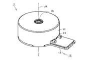
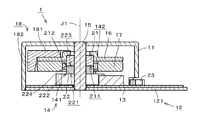
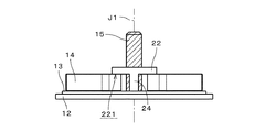
図1は、本発明の例示的な第1の実施形態に係る振動モータ1の外観を示す斜視図である。図2は、振動モータ1の縦断面図である。図2では、細部の断面における平行斜線を省略している。また、図2では、断面よりも奥側の構成も併せて描いている。図3は、振動モータ1の回転部および静止部の斜視図である。図4は、振動モータ1の静止部の斜視図である。図5は、振動モータ1の静止部の平面図である。図6は、振動モータ1の静止部の側面図である。図6は、図5中の左側から振動モータ1の静止部を見た図である。
FIG. 1 is a perspective view showing an appearance of a
振動モータ1はコイン型のブラシレスモータである。振動モータ1は、例えば、携帯電話等の移動体通信装置の無音報知デバイスとして用いられる。
The
振動モータ1は、カバー部11と、ベース部12と、を含む。カバー部11は、有蓋略円筒状である。ベース部12は、上下方向を向く中心軸J1に対して垂直に広がる。カバー部11は、ベース部12の外縁部に固定される。ベース部12は、カバー部11の下部の開口を塞ぐ。カバー部11およびベース部12は、例えば、金属製である。カバー部11とベース部12とは、例えば、溶接にて接続される。ベース部12は、中心軸J1に略垂直な方向に延びるベース突出部121を含む。ベース突出部121は、カバー部11から径方向外方に突出する。
The
振動モータ1は、回路基板13と、コイル部14と、シャフト15と、ロータホルダ16と、磁石部17と、偏心錘18と、をさらに含む。振動モータ1は、軸受部21と、スペーサ22と、をさらに含む。ベース部12、回路基板13、コイル部14、シャフト15およびスペーサ22は、静止部に含まれる。軸受部21、ロータホルダ16、磁石部17および偏心錘18は、回転部に含まれる。図3は、振動モータ1からカバー部11を除いた図である。図4ないし図6は、振動モータ1からカバー部11および回転部を除いた図である。
The
回路基板13は、ベース部12上に配置される。回路基板13は、接着剤を用いてベース部12に接着される。なお、本実施形態において、接着剤の概念には、両面テープや粘着剤等も含まれる。回路基板13は、可撓性を有するフレキシブル基板(FPC:Flexible printed circuits)である。回路基板13上には電子部品23が実装される。
The
コイル部14は、回路基板13上に取り付けられる。コイル部14は、回路基板13に電気的に接続される。コイル部14は、複数のコイル141を含む。複数のコイル141は、シャフト15の周囲に配置される。図4ないし図6に示す例では、コイル部14は2つのコイル141を含む。2つのコイル141は、シャフト15を挟んで反対側に位置する。コイル部14に含まれるコイル141の数は、3以上であってもよい。各コイル141は、回路基板13上に接着剤を用いて接着される。図4に示す例では、各コイル141は、平面視において、シャフト15に平行な軸を囲み、かつ、シャフト15が外側に位置する環状である。
The
シャフト15は、中心軸J1を中心として配置される。シャフト15の下端は、ベース部12に固定される。シャフト15は、中心軸J1に沿ってベース部12から上方へと突出する。シャフト15の上端は、カバー部11の天蓋部の中央部に固定される。シャフト15は、例えば、溶接および圧入によりベース部12およびカバー部11に固定される。シャフト15は、図6に示す空隙150を介して複数のコイル141と径方向にそれぞれ対向する。換言すれば、コイル部14は、シャフト15と空隙150を介して径方向に対向する。空隙150には、振動モータ1を構成する部材は配置されない。シャフト15は、例えば、金属製である。シャフト15は、他の材料により形成されてもよい。
The
スペーサ22は、中央に貫通孔を有する環状の部材である。図4ないし図6に示す例では、スペーサ22は円環状である。詳細には、スペーサ22は、中心軸J1を中心とする略円筒状である。スペーサ22の貫通孔にはシャフト15が挿入される。スペーサ22は、例えば、圧入によりシャフト15に取り付けられる。スペーサ22は、コイル部14よりも上方に配置され、シャフト15に固定される。スペーサ22は、例えば、樹脂により形成される。スペーサ22は、他の材料により形成されてもよい。また、スペーサ22は、圧入以外の方法によりシャフト15に取り付けられてもよい。
The
スペーサ22の下面221は、コイル部14の上面と上下方向に対向する。図4および図6に示す例では、スペーサ22の下面221は、コイル部14の上面に接する。詳細には、スペーサ22の下面221は、2つのコイル141のそれぞれの上面142に接する。図4および図5に示すように、各コイル141の上面142の内周縁143全体は、スペーサ22の下面221の外縁222よりも径方向外側に位置する。また、各コイル141の上面142の外周縁144の一部は、スペーサ22の下面221の外縁222よりも径方向内側に位置する。換言すれば、スペーサ22の下面221は、各コイル141の上面142の一部とは重なるが、上面142の中央部に設けられた開口には重ならない。
The
軸受部21は、中央に貫通孔を有する環状の部材である。図2に示す例では、軸受部21は円環状である。詳細には、軸受部21は、中心軸J1を中心とする略円筒状である。軸受部21の貫通孔にはシャフト15が挿入される。軸受部21は、コイル部14よりも上方にて、シャフト15に対して回転可能に取り付けられる。軸受部21は、また、スペーサ22よりも上方に配置される。換言すれば、スペーサ22は、軸受部21とコイル部14との間にてシャフト15に取り付けられる。
The bearing
図2に示すように、スペーサ22の上面223は、軸受部21の下面211に接する。図2に示す例では、スペーサ22の上面223の外縁224は、全周に亘って軸受部21の下面211の外縁212と重なる。換言すれば、スペーサ22の上面223の外径は、軸受部21の下面211の外径と略等しい。軸受部21は、滑り軸受である。軸受部21は、他の種類の軸受であってもよい。軸受部21は、例えば、焼結金属により形成される。好ましくは、軸受部21には潤滑油を含浸させている。軸受部21は、他の材料により形成されてもよい。
As shown in FIG. 2, the
ロータホルダ16は、略円環状の部材である。ロータホルダ16は、軸受部21に取り付けられる。詳細には、略円環板状のロータホルダ16の内周部が、軸受部21の上端面および外周面の上部に固定される。これにより、ロータホルダ16は、軸受部21により、シャフト15に対して回転可能に支持される。ロータホルダ16は、例えば、金属製である。
The
磁石部17は、中心軸J1を中心とする略円環状の部材である。磁石部17は、ロータホルダ16に取り付けられる。詳細には、略円筒状の磁石部17の上面が、ロータホルダ16の下面に取り付けられる。磁石部17は、コイル部14の上方に配置され、コイル部14と空隙を介して上下方向に対向する。磁石部17は、軸受部21およびスペーサ22の周囲に配置される。軸受部21は、磁石部17の径方向内側に位置し、空隙を介して磁石部17と径方向に対向する。スペーサ22は、磁石部17の径方向内側に位置する。換言すれば、スペーサ22の上面223は、磁石部17の下面よりも上方に位置する。スペーサ22は、空隙を介して磁石部17と径方向に対向する。
The
偏心錘18は、図2および図3に示す例では、有蓋円筒状の部材の左半分に相当する形状である。偏心錘18は、平面視において略半円状である。偏心錘18は、ロータホルダ16に取り付けられる。詳細には、偏心錘18の天蓋部181の下面が、ロータホルダ16の上面に、例えば、接着剤を介して取り付けられる。偏心錘18の側壁部182は、ロータホルダ16および磁石部17の側方の一部を覆う。偏心錘18の側壁部182の下端は、磁石部17の下端と上下方向においておよそ同じ位置に位置する。偏心錘18の重心は、中心軸J1から径方向に離れている。
In the example shown in FIGS. 2 and 3, the
カバー部11は、ロータホルダ16および偏心錘18の上方および側方を覆う。カバー部11は、ロータホルダ16および偏心錘18の全体を覆う必要はなく、開口等が形成されることにより、ロータホルダ16および偏心錘18の少なくとも一部を覆うものであればよい。既述のように、カバー部11は、シャフト15の上端に固定され、ベース部12の外縁部にも固定される。
The
振動モータ1では、回路基板13を介してコイル部14に電流が供給されることにより、コイル部14と磁石部17との間にトルクが発生する。これにより、軸受部21、ロータホルダ16、磁石部17および偏心錘18が、シャフト15を中心として回転する。上述のように、偏心錘18の重心は中心軸J1から径方向に離れているため、偏心錘18の回転により振動が発生する。
In the
以上に説明したように、振動モータ1では、スペーサ22は、軸受部21とコイル部14との間にてシャフト15に取り付けられる。コイル部14は、シャフト15と空隙150を介して径方向に対向する。スペーサ22の上面223は、軸受部21の下面211に接する。また、スペーサ22の下面221は、コイル部14の上面142と上下方向に対向する。
As described above, in the
このため、振動モータ1では、コイル部の径方向内側にスペーサが配置される振動モータ(以下、「比較例の振動モータ」という。)に比べて、コイル部14を径方向においてシャフト15に近接して配置することができる。これにより、コイル部14および偏心錘18の体積減少を抑制して振動量の減少を抑制しつつ、振動モータ1を径方向に小型化することができる。また、振動モータ1をあまり小型化しない場合、コイル部14および/または偏心錘18を大型化してトルクを増大することができるため、振動量を増大することができる。
For this reason, in the
上述のように、スペーサ22の下面221は、コイル部14の上面142に接する。これにより、振動モータ1を上下方向に小型化することができる。また、振動モータ1の落下時等に、コイル部14の上下方向への移動を制限することができるため、コイル部14が回路基板13から剥離することを抑制することができる。さらに、コイル部14の上面142の上下方向の位置が不揃いになることを抑制することができるため、コイル部14と磁石部17との間の上下方向の距離、すなわち、コイル部14と磁石部17との間の空隙を容易に確保することができる。
As described above, the
上述のように、スペーサ22は、圧入によりシャフト15に取り付けられる。このため、スペーサ22をシャフト15に対して強固に固定することができる。その結果、振動モータ1の落下時等に、コイル部14が回路基板13から剥離することを、より一層抑制することができる。また、コイル部14と磁石部17との間の上下方向の距離を、さらに容易に確保することができる。
As described above, the
振動モータ1では、スペーサ22は円環状である。このように、スペーサ22の形状を簡素化することにより、スペーサ22を容易に製造することができる。また、スペーサ22は、磁石部17の径方向内側に位置する。このため、磁石部がスペーサよりも上方に位置する場合に比べて、振動モータ1を上下方向に小型化することができる。
In the
上述のように、スペーサ22の上面223の外縁224は、全周に亘って、軸受部21の下面211の外縁212と重なる。このため、軸受部21の下面211がスペーサ22の上面223から径方向外側にはみ出した状態で、回転部が回転することを抑制することができる。その結果、振動モータ1における回転摺動を安定させることができる。
As described above, the
上述のように、各コイル141の上面142の内周縁143全体は、スペーサ22の下面221の外縁222よりも径方向外側に位置する。また、各コイル141の上面142の外周縁144の一部は、スペーサ22の下面221の外縁222よりも径方向内側に位置する。これにより、スペーサ22を径方向に小型化することができる。
As described above, the entire inner
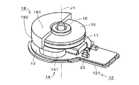
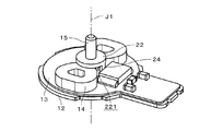
振動モータ1は、図7ないし図9に示すように、スペーサ22の下面221から下方に突出するスペーサ支持部24を含んでいてもよい。図7および図8は、それぞれ異なる方向から見た振動モータ1の静止部の斜視図である。図9は、静止部の側面図である。図9は、図6と同じ方向から静止部を見た図である。図9では、図の理解を容易にするために、シャフト15に平行斜線を付す。
As shown in FIGS. 7 to 9, the
図7ないし図9に示す例では、2つのスペーサ支持部24が、スペーサ22の下面221からシャフト15に略平行に延びる。スペーサ支持部24は、1つであっても、3つ以上であってもよい。各スペーサ支持部24の下端は、回路基板13またはベース部12に接する。図8に示す例では、各スペーサ支持部24は、回路基板13に設けられた貫通孔を介してベース部12に接する。
In the example shown in FIGS. 7 to 9, the two
スペーサ支持部24が設けられることにより、振動モータ1の落下時等に、回転部からスペーサ22を介してコイル部14に加わる力や衝撃を低減することができる。その結果、振動モータ1の落下時等に、コイル部14の破損を抑制することができる。
By providing the
図10は、本発明の例示的な第2の実施形態に係る振動モータ1aの縦断面図である。振動モータ1aは、図2に示す振動モータ1のロータホルダ16およびスペーサ22とは形状が異なるロータホルダ16aおよびスペーサ22aを含む。振動モータ1aの他の構成は、図1ないし図6に示す振動モータ1と同様であり、対応する構成に同符号を付す。
FIG. 10 is a longitudinal sectional view of a vibration motor 1a according to a second exemplary embodiment of the present invention. The vibration motor 1a includes a
ロータホルダ16aは、軸受部21に取り付けられる。詳細には、ロータホルダ16aの内周部161が、軸受部21の上端面および外周面に取り付けられる。ロータホルダ16aの内周部161は、軸受部21の外周面のおよそ全面に亘って固定される。これにより、ロータホルダ16aを軸受部21に強固に取り付けることができる。ロータホルダ16aは、内周部161の下端部から径方向外方かつ上方に折り返され、さらに、径方向外方に折り返されて径方向外方へと広がる。
The
スペーサ22aは、磁石部17の径方向内側に位置する。スペーサ22aは、中心軸J1を中心とする円環状である。スペーサ22aの上面223の外縁224は、全周に亘って、軸受部21の下面211の外縁212よりも径方向外側に位置する。換言すれば、スペーサ22aの上面223の外径は、軸受部21の下面211の外径よりも大きい。このため、回転部の回転時に、軸受部21の下面211がスペーサ22aの上面223から径方向外側にはみ出すことを抑制することができる。その結果、振動モータ1aにおける回転摺動を安定させることができる。
The
振動モータ1aでは、カバー部11の天蓋部において、シャフト15との接合部にカバー突出部111が設けられる。カバー突出部111は、シャフト15に沿って下方に突出する。これにより、カバー部11とシャフト15との締結長が長くなる。その結果、カバー部11を、より強固にシャフト15に固定することができる。
In the vibration motor 1 a, the
図11は、本発明の例示的な第3の実施形態に係る振動モータ1bの縦断面図である。図12は、振動モータ1bの回転部および静止部の斜視図である。図11および図12では、図2および図3とは偏心錘18の向きが90度異なる。振動モータ1bは、図2に示す振動モータ1のロータホルダ16、軸受部21およびスペーサ22とは形状が異なるロータホルダ16b、軸受部21bおよびスペーサ22bを含む。振動モータ1bの他の構成は、図1ないし図6に示す振動モータ1と同様であり、対応する構成に同符号を付す。
FIG. 11 is a longitudinal sectional view of a
スペーサ22bは、磁石部17よりも下方に位置する。スペーサ22bは円環状である。詳細には、スペーサ22bは、中心軸J1を中心とする円環板状である。ロータホルダ16bは、中心軸J1を中心とする略円環板状である。軸受部21bは、例えば、樹脂製であり、ロータホルダ16bおよび偏心錘18とインサート成形により一体的に形成される。このように、回転部の大部分がインサート成形により形成されることにより、振動モータ1bを構成する部品の数を少なくすることができる。その結果、振動モータ1bの組み立てを簡素化することができる。
The
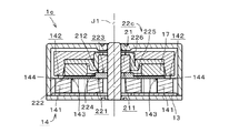
図13は、本発明の例示的な第4の実施形態に係る振動モータ1cの縦断面図である。図14は、振動モータ1cの静止部の斜視図である。図13では、図10とは90度異なる断面を示す。振動モータ1cは、図10に示す振動モータ1aのスペーサ22aとは形状が異なるスペーサ22cを含む。振動モータ1cの他の構成は、図10に示す振動モータ1aと同様であり、対応する構成に同符号を付す。
FIG. 13 is a longitudinal sectional view of a
スペーサ22cは、中心軸J1を中心とする円環状である。スペーサ22cは、円環板状のスペーサ下部225と、スペーサ下部225の内周部から上方に突出する円環板状のスペーサ上部226と、を含む。スペーサ下部225の外径は、スペーサ上部226の外径よりも大きい。スペーサ上部226の上面はスペーサ22cの上面223であり、スペーサ下部225の下面はスペーサ22cの下面221である。スペーサ上部226は、磁石部17の径方向内側に位置する。
The
スペーサ22cの上面223の外縁224は、全周に亘って、軸受部21の下面211の外縁212よりも径方向外側に位置する。このため、回転部の回転時に、軸受部21の下面211がスペーサ22cの上面223から径方向外側にはみ出すことを抑制することができる。その結果、振動モータ1cにおける回転摺動を安定させることができる。
The
各コイル141の上面142の内周縁143全体は、スペーサ22cの下面221の外縁222よりも径方向内側に位置する。また、各コイル141の上面142の外周縁144の一部は、スペーサ22cの下面221の外縁222よりも径方向外側に位置する。換言すれば、スペーサ22cの下面221は、コイル部14の各コイル141の上面142の中央部に設けられた開口全体と重なる。
The entire inner
これにより、振動モータ1cの落下時等に、コイル部14の上下方向への移動をさらに制限することができるため、コイル部14が回路基板13から剥離することをより一層抑制することができる。また、コイル部14の上面142の上下方向の位置が不揃いになることをさらに抑制することができるため、コイル部14と磁石部17との間の上下方向の距離をより一層容易に確保することができる。
Thereby, when the
図15は、本発明の例示的な第5の実施形態に係る振動モータ1dの縦断面図である。図15では、図10とは90度異なる断面を示す。振動モータ1dは、図10に示す振動モータ1aの偏心錘18とは形状が異なる偏心錘18dを含む。振動モータ1dの他の構成は、図10に示す振動モータ1aと同様であり、対応する構成に同符号を付す。
FIG. 15 is a longitudinal sectional view of a vibration motor 1d according to a fifth exemplary embodiment of the present invention. FIG. 15 shows a cross section that is 90 degrees different from FIG. The vibration motor 1d includes an
偏心錘18dは、側壁部182の下端が磁石部17の下端よりも下方に位置する点を除き、図10に示す偏心錘18とおよそ同様の形状を有する。振動モータ1dでは、偏心錘18dの一部である側壁部182の下端部が、コイル部14よりも径方向外側にて、コイル部14とカバー部11との間に位置する。これにより、振動モータ1dの大型化を抑制しつつ偏心錘18dを大型化し、振動モータ1dの振動量を増大させることができる。
The
上記振動モータ1,1a〜1dでは、様々な変更が可能である。
Various changes can be made in the
例えば、振動モータ1,1a〜1dでは、偏心錘18,18dの天蓋部181が省略され、磁石部17の径方向外側のみに偏心錘18,18dが設けられてもよい。
For example, in the
スペーサ22,22a〜22cの下面221は、必ずしもコイル部14の上面142に接する必要はなく、コイル部14の上面142と上下方向に対向していれば、当該上面142と離間していてもよい。スペーサ22,22a〜22cは、必ずしも円環状である必要はない。例えば、図16に示すスペーサ22eは、略円環状の中央部227と、中央部227の外周部から2つのコイル141上にそれぞれ広がる2つの周辺部228と、を含む。周辺部228がコイル141の上面142と上下方向に対向することにより、振動モータの落下時等に、コイル部14が回路基板13から剥離することを抑制することができる。また、コイル部14と磁石部17との間の上下方向の距離を容易に確保することができる。
The
振動モータ1,1a〜1dにおける各部材の取り付けや固定は、間接的でもよい。例えば、回路基板13は、ベース部12上に配置されるのであれば、回路基板13とベース部12との間に他の部材が介在してもよい。コイル部14も、他の部材を介して回路基板13に取り付けられてよい。シャフト15のカバー部11およびベース部12への取り付け、磁石部17のロータホルダ16,16a,16bへの取り付け、偏心錘18,18dのロータホルダ16,16a,16bへの取り付け、カバー部11とベース部12との固定等も、他の部材が介在してもよい。
The attachment and fixation of each member in the
上記実施の形態および各変形例における構成は、相互に矛盾しない限り適宜組み合わされてよい。 The configurations in the above-described embodiments and modifications may be combined as appropriate as long as they do not contradict each other.
本発明に係る振動モータは、様々な用途の振動モータとして利用可能である。好ましくは、携帯電話等の移動体通信装置の無音報知デバイスとして用いられる。 The vibration motor according to the present invention can be used as a vibration motor for various applications. Preferably, it is used as a silent notification device of a mobile communication device such as a mobile phone.
1,1a〜1d 振動モータ
11 カバー部
12 ベース部
13 回路基板
14 コイル部
15 シャフト
16,16a,16b ロータホルダ
17 磁石部
18,18d 偏心錘
21,21b 軸受部
22,22a〜22c,22e スペーサ
24 スペーサ支持部
141 コイル
142 (コイルの)上面
143 (コイルの上面の)内周縁
144 (コイルの上面の)外周縁
150 空隙
211 (軸受部の)下面
212 (軸受部の下面の)外縁
221 (スペーサの)下面
222 (スペーサの下面の)外縁
223 (スペーサの)上面
224 (スペーサの上面の)外縁
J1 中心軸
DESCRIPTION OF
Claims (10)
前記ベース部に下端が固定され、前記中心軸に沿って上方へと突出するシャフトと、
前記ベース部上に配置される回路基板と、
前記回路基板上に取り付けられ、前記シャフトと空隙を介して径方向に対向するコイル部と、
前記コイル部よりも上方にて前記シャフトに対して回転可能に取り付けられる軸受部と、
前記軸受部に取り付けられるロータホルダと、
前記ロータホルダに取り付けられる磁石部と、
前記ロータホルダに取り付けられる偏心錘と、
前記軸受部と前記コイル部との間にて前記シャフトに取り付けられ、上面が前記軸受部の下面に接するスペーサと、
前記ロータホルダおよび前記偏心錘の上方および側方の少なくとも一部を覆い、前記シャフトの上端および前記ベース部の外縁部に固定されるカバー部と、
を備え、
前記スペーサの下面は、前記コイル部の上面と上下方向に対向し、
前記スペーサの下面から下方に突出し、前記回路基板または前記ベース部に接するスペーサ支持部をさらに備える、振動モータ。 A base portion extending perpendicular to the central axis facing the up and down direction;
A shaft having a lower end fixed to the base portion and projecting upward along the central axis;
A circuit board disposed on the base portion;
A coil portion mounted on the circuit board and opposed in the radial direction via the shaft and a gap;
A bearing portion rotatably attached to the shaft above the coil portion;
A rotor holder attached to the bearing portion;
A magnet portion attached to the rotor holder;
An eccentric weight attached to the rotor holder;
A spacer that is attached to the shaft between the bearing portion and the coil portion, and whose upper surface is in contact with the lower surface of the bearing portion;
A cover portion that covers at least a part of the rotor holder and the eccentric weight above and to the side, and is fixed to an upper end of the shaft and an outer edge portion of the base portion;
With
The lower surface of the spacer faces the upper surface of the coil portion in the vertical direction ,
The vibration motor further includes a spacer support portion that protrudes downward from the lower surface of the spacer and contacts the circuit board or the base portion .
平面視において、各コイルは、前記シャフトに平行な軸を囲み、かつ、前記シャフトが外側に位置する環状であり、
前記各コイルの上面の内周縁全体が、前記スペーサの下面の外縁よりも径方向外側に位置し、
前記各コイルの上面の外周縁の一部が、前記スペーサの下面の前記外縁よりも径方向内側に位置する、請求項1に記載の振動モータ。 The coil portion includes a plurality of coils disposed around the shaft;
In a plan view, each coil has an annular shape that surrounds an axis parallel to the shaft, and the shaft is located outside.
The entire inner peripheral edge of the upper surface of each coil is located radially outside the outer edge of the lower surface of the spacer,
2. The vibration motor according to claim 1, wherein a part of the outer peripheral edge of the upper surface of each coil is located radially inward from the outer edge of the lower surface of the spacer.
平面視において、各コイルは、前記シャフトに平行な軸を囲み、かつ、前記シャフトが外側に位置する環状であり、
前記各コイルの上面の内周縁全体が、前記スペーサの下面の外縁よりも径方向内側に位置し、
前記各コイルの上面の外周縁の一部が、前記スペーサの下面の前記外縁よりも径方向外側に位置する、請求項1に記載の振動モータ。 The coil portion includes a plurality of coils disposed around the shaft;
In a plan view, each coil has an annular shape that surrounds an axis parallel to the shaft, and the shaft is located outside.
The entire inner peripheral edge of the upper surface of each coil is located radially inward from the outer edge of the lower surface of the spacer,
2. The vibration motor according to claim 1, wherein a part of the outer peripheral edge of the upper surface of each coil is located radially outside the outer edge of the lower surface of the spacer.
前記ベース部に下端が固定され、前記中心軸に沿って上方へと突出するシャフトと、
前記ベース部上に配置される回路基板と、
前記回路基板上に取り付けられ、前記シャフトと空隙を介して径方向に対向するコイル部と、
前記コイル部よりも上方にて前記シャフトに対して回転可能に取り付けられる軸受部と、
前記軸受部に取り付けられるロータホルダと、
前記ロータホルダに取り付けられる磁石部と、
前記ロータホルダに取り付けられる偏心錘と、
前記軸受部と前記コイル部との間にて前記シャフトに取り付けられ、上面が前記軸受部の下面に接するスペーサと、
前記ロータホルダおよび前記偏心錘の上方および側方の少なくとも一部を覆い、前記シャフトの上端および前記ベース部の外縁部に固定されるカバー部と、
を備え、
前記スペーサの下面は、前記コイル部の上面と上下方向に対向し、
前記コイル部が、前記シャフトの周囲に配置される複数のコイルを含み、
平面視において、各コイルは、前記シャフトに平行な軸を囲み、かつ、前記シャフトが外側に位置する環状であり、
前記各コイルの上面の内周縁全体が、前記スペーサの下面の外縁よりも径方向内側に位置し、
前記各コイルの上面の外周縁の一部が、前記スペーサの下面の前記外縁よりも径方向外側に位置する、振動モータ。 A base portion extending perpendicular to the central axis facing the up and down direction;
A shaft having a lower end fixed to the base portion and projecting upward along the central axis;
A circuit board disposed on the base portion;
A coil portion mounted on the circuit board and opposed in the radial direction via the shaft and a gap;
A bearing portion rotatably attached to the shaft above the coil portion;
A rotor holder attached to the bearing portion;
A magnet portion attached to the rotor holder;
An eccentric weight attached to the rotor holder;
A spacer that is attached to the shaft between the bearing portion and the coil portion, and whose upper surface is in contact with the lower surface of the bearing portion;
A cover portion that covers at least a part of the rotor holder and the eccentric weight above and to the side, and is fixed to an upper end of the shaft and an outer edge portion of the base portion;
With
The lower surface of the spacer faces the upper surface of the coil portion in the vertical direction ,
The coil portion includes a plurality of coils disposed around the shaft;
In a plan view, each coil has an annular shape that surrounds an axis parallel to the shaft, and the shaft is located outside.
The entire inner peripheral edge of the upper surface of each coil is located radially inward from the outer edge of the lower surface of the spacer,
A vibration motor in which a part of the outer peripheral edge of the upper surface of each coil is located radially outside the outer edge of the lower surface of the spacer .
Priority Applications (4)
| Application Number | Priority Date | Filing Date | Title |
|---|---|---|---|
| JP2014234779A JP6470552B2 (en) | 2014-11-19 | 2014-11-19 | Vibration motor |
| CN201510746785.1A CN105610272A (en) | 2014-11-19 | 2015-11-05 | Vibration motor |
| CN201520878454.9U CN205081622U (en) | 2014-11-19 | 2015-11-05 | Vibration motor |
| US14/945,604 US9979258B2 (en) | 2014-11-19 | 2015-11-19 | Vibration motor |
Applications Claiming Priority (1)
| Application Number | Priority Date | Filing Date | Title |
|---|---|---|---|
| JP2014234779A JP6470552B2 (en) | 2014-11-19 | 2014-11-19 | Vibration motor |
Publications (2)
| Publication Number | Publication Date |
|---|---|
| JP2016100945A JP2016100945A (en) | 2016-05-30 |
| JP6470552B2 true JP6470552B2 (en) | 2019-02-13 |
Family
ID=55433996
Family Applications (1)
| Application Number | Title | Priority Date | Filing Date |
|---|---|---|---|
| JP2014234779A Expired - Fee Related JP6470552B2 (en) | 2014-11-19 | 2014-11-19 | Vibration motor |
Country Status (3)
| Country | Link |
|---|---|
| US (1) | US9979258B2 (en) |
| JP (1) | JP6470552B2 (en) |
| CN (2) | CN205081622U (en) |
Families Citing this family (11)
| Publication number | Priority date | Publication date | Assignee | Title |
|---|---|---|---|---|
| JP6470552B2 (en) * | 2014-11-19 | 2019-02-13 | 日本電産セイミツ株式会社 | Vibration motor |
| JP6531261B2 (en) * | 2015-10-16 | 2019-06-19 | 日本電産セイミツ株式会社 | Vibration motor |
| US10396645B2 (en) * | 2015-10-16 | 2019-08-27 | Nidec Seimitsu Corporation | Vibration motor |
| JP2017074572A (en) * | 2015-10-16 | 2017-04-20 | 日本電産セイミツ株式会社 | Vibration motor |
| JP6531260B2 (en) * | 2015-10-16 | 2019-06-19 | 日本電産セイミツ株式会社 | Vibration motor |
| JP7232572B2 (en) * | 2017-02-21 | 2023-03-03 | セイコーインスツル株式会社 | Vibration generator and electronic equipment |
| KR102167407B1 (en) * | 2018-02-28 | 2020-10-19 | 주식회사 이엠텍 | Wide band linear motor |
| CN109038939B (en) * | 2018-07-13 | 2021-04-20 | 浙江省东阳市东磁诚基电子有限公司 | Permanent magnet alternating current flat vibration motor and use method |
| CN112803700A (en) * | 2021-03-08 | 2021-05-14 | 浙江省东阳市东磁诚基电子有限公司 | Rotor subassembly and brushless vibrating motor |
| WO2022188390A1 (en) * | 2021-03-08 | 2022-09-15 | 浙江省东阳市东磁诚基电子有限公司 | Rotor assembly and brushless vibration electric motor |
| US11770060B2 (en) * | 2021-05-14 | 2023-09-26 | Delta Electronics, Inc. | Vibration motor |
Family Cites Families (16)
| Publication number | Priority date | Publication date | Assignee | Title |
|---|---|---|---|---|
| KR200268109Y1 (en) * | 2001-12-06 | 2002-03-15 | 김정훈 | Flat noncommutator vibration motor |
| US6998742B2 (en) * | 2002-10-28 | 2006-02-14 | Tokyo Parts Industrial Co., Ltd. | Axial-air-gap brushless vibration motor containing drive circuit |
| KR100519811B1 (en) * | 2003-06-20 | 2005-10-10 | 삼성전기주식회사 | Vibration motor |
| JP2005137036A (en) * | 2003-10-28 | 2005-05-26 | Tokyo Parts Ind Co Ltd | Axial air gap type single phase brushless motor |
| JP2006094643A (en) | 2004-09-24 | 2006-04-06 | Nidec Copal Corp | Single-phase brushless motor |
| JP4073451B2 (en) * | 2005-08-19 | 2008-04-09 | 東京パーツ工業株式会社 | Axial gap type brushless vibration motor |
| KR100737529B1 (en) * | 2005-09-27 | 2007-07-10 | 엘지이노텍 주식회사 | Slim vibration motor |
| JP2008049246A (en) * | 2006-08-23 | 2008-03-06 | Tokyo Parts Ind Co Ltd | Eccentric rotor and brushless vibration motor having the same rotor |
| JP4187773B1 (en) | 2007-05-17 | 2008-11-26 | 東京パーツ工業株式会社 | An axial gap type brushless vibration motor equipped with a thin stator and the same stator |
| KR101416185B1 (en) * | 2008-03-11 | 2014-07-09 | 엘지이노텍 주식회사 | Flat vibration motor |
| JP2011067082A (en) * | 2009-08-19 | 2011-03-31 | Sanyo Electric Co Ltd | Flat vibration motor |
| JPWO2012008248A1 (en) * | 2010-07-12 | 2013-09-09 | 日本電産セイミツ株式会社 | Flat vibration motor |
| JP5849321B2 (en) * | 2010-08-04 | 2016-01-27 | 日本電産セイミツ株式会社 | Flat vibration motor |
| JP6247113B2 (en) * | 2014-02-20 | 2017-12-13 | 日本電産セイミツ株式会社 | Vibration motor |
| JP2015199008A (en) * | 2014-04-04 | 2015-11-12 | 日本電産セイミツ株式会社 | vibration motor |
| JP6470552B2 (en) * | 2014-11-19 | 2019-02-13 | 日本電産セイミツ株式会社 | Vibration motor |
-
2014
- 2014-11-19 JP JP2014234779A patent/JP6470552B2/en not_active Expired - Fee Related
-
2015
- 2015-11-05 CN CN201520878454.9U patent/CN205081622U/en not_active Expired - Fee Related
- 2015-11-05 CN CN201510746785.1A patent/CN105610272A/en active Pending
- 2015-11-19 US US14/945,604 patent/US9979258B2/en not_active Expired - Fee Related
Also Published As
| Publication number | Publication date |
|---|---|
| US9979258B2 (en) | 2018-05-22 |
| CN105610272A (en) | 2016-05-25 |
| CN205081622U (en) | 2016-03-09 |
| US20160141935A1 (en) | 2016-05-19 |
| JP2016100945A (en) | 2016-05-30 |
Similar Documents
| Publication | Publication Date | Title |
|---|---|---|
| JP6470552B2 (en) | Vibration motor | |
| KR101406207B1 (en) | Brushless direct current vibrational motor | |
| US8378539B2 (en) | Flat vibration motor | |
| JP6609435B2 (en) | Vibration motor | |
| JP2005012987A (en) | Vibrating motor | |
| US9166452B1 (en) | Spindle motor, disk drive apparatus, and electronic device | |
| JP2015154496A (en) | inner rotor type motor | |
| JP2015199008A (en) | vibration motor | |
| US20170187261A1 (en) | Vibration motor, vibrator-attached board, silent notification device, and method for manufacturing vibration motor | |
| JP2017153315A (en) | Vibration motor | |
| JP2017034866A (en) | Vibration motor | |
| JP2017153314A (en) | Vibration motor | |
| JP6338961B2 (en) | Vibration motor | |
| JP6243379B2 (en) | motor | |
| KR101188096B1 (en) | Bearing assembly and motor including the same | |
| JP6576727B2 (en) | Brushless motor | |
| US9118222B2 (en) | Outer rotor-type brushless motor | |
| JP6553153B2 (en) | motor | |
| JPWO2019111879A1 (en) | Gear system with motor | |
| JP2019030112A (en) | motor | |
| US8629584B2 (en) | Base assembly for motor and fan motor including the same | |
| JP2009207277A (en) | Compact motor | |
| JP5181643B2 (en) | motor | |
| JP2008099355A (en) | Bearing for motor and vibrating motor | |
| US9692273B2 (en) | Spindle motor, electronics device and disk drive apparatus |
Legal Events
| Date | Code | Title | Description |
|---|---|---|---|
| A621 | Written request for application examination |
Free format text: JAPANESE INTERMEDIATE CODE: A621 Effective date: 20171102 |
|
| A977 | Report on retrieval |
Free format text: JAPANESE INTERMEDIATE CODE: A971007 Effective date: 20180822 |
|
| A131 | Notification of reasons for refusal |
Free format text: JAPANESE INTERMEDIATE CODE: A131 Effective date: 20180828 |
|
| A521 | Request for written amendment filed |
Free format text: JAPANESE INTERMEDIATE CODE: A523 Effective date: 20181025 |
|
| TRDD | Decision of grant or rejection written | ||
| A01 | Written decision to grant a patent or to grant a registration (utility model) |
Free format text: JAPANESE INTERMEDIATE CODE: A01 Effective date: 20190115 |
|
| A61 | First payment of annual fees (during grant procedure) |
Free format text: JAPANESE INTERMEDIATE CODE: A61 Effective date: 20190118 |
|
| R150 | Certificate of patent or registration of utility model |
Ref document number: 6470552 Country of ref document: JP Free format text: JAPANESE INTERMEDIATE CODE: R150 |
|
| LAPS | Cancellation because of no payment of annual fees |