JP6468605B2 - Method for attaching traveling device in concrete formwork support device - Google Patents
Method for attaching traveling device in concrete formwork support device Download PDFInfo
- Publication number
- JP6468605B2 JP6468605B2 JP2016004517A JP2016004517A JP6468605B2 JP 6468605 B2 JP6468605 B2 JP 6468605B2 JP 2016004517 A JP2016004517 A JP 2016004517A JP 2016004517 A JP2016004517 A JP 2016004517A JP 6468605 B2 JP6468605 B2 JP 6468605B2
- Authority
- JP
- Japan
- Prior art keywords
- support device
- rail
- traveling
- foam
- tunnel
- Prior art date
- Legal status (The legal status is an assumption and is not a legal conclusion. Google has not performed a legal analysis and makes no representation as to the accuracy of the status listed.)
- Active
Links
Images


Description
本発明は、トンネル覆工型枠等のコンクリート型枠を支持するための支持装置に対する走行装置の取り付け方法に関するものである。 The present invention relates to a method for attaching a traveling device to a support device for supporting a concrete formwork such as a tunnel lining formwork.
特許文献1には、トンネル覆工用のコンクリート型枠を支持するための支持装置が開示されている。
図9(a),(c)に示すように、このようなコンクリート型枠12(以下、単に型枠という)は、ガントリ形状の支持装置11上に支持される。支持装置11は、トンネルT内の型枠の組み立て位置に設置される。
Patent Document 1 discloses a support device for supporting a concrete formwork for tunnel lining.
As shown in FIGS. 9A and 9C, such a concrete mold 12 (hereinafter simply referred to as a mold) is supported on a gantry-
図9(a),(c)に示す型枠12は、同型枠12の頂部に位置する複数枚の天井フォーム13,その各天井フォーム13の両側下部に位置する複数枚のサイドフォーム14及び各サイドフォーム14の下側に位置する複数枚のインバートフォーム15をトンネルTの延長方向に沿って並設している。これらの各フォーム13,14,15は、補強枠(図10参照)上にコンクリート成形面を形成するスキンプレート131,141,151を固定して構成されている。
The
前記支持装置11の支持脚18にはジャッキ16が備えられている。このジャッキ16の伸縮により支持装置11が昇降される。そして、支持装置11の下降状態において支持装置11に天井フォーム13が組み付けられるとともに、支持装置11が上昇される。その後、サイドフォーム14及びインバートフォーム15の順で支持装置11に組み付けられて、型枠12となる。
The
そして、支持装置11の上昇状態において、型枠12のスキンプレート131,141,151と、トンネルの内壁面との間にコンクリートCが打設される。
以下に、型枠12の従来の組み立て方法をさらに詳細に説明する。
Then, in the ascending state of the
Below, the conventional assembly method of the
まず、図1(a),(c)及び図2(a),(c)に示すように、トンネルT内の型枠組み立て位置に支持装置11が設置される。このとき、支持脚18のジャッキ16が収縮されているため、支持装置11は、全体が下降位置にある。この下降状態で、支持装置11の上部に複数の天井フォーム13が並設状態で支持される。
First, as shown in FIGS. 1A and 1C and FIGS. 2A and 2C, the
次いで、図3(a),(c)に示すように、支持脚18のジャッキ16が伸張されて、天井フォーム13がトンネルTの内周頂面に接近するように、支持装置11が上昇される。
Next, as shown in FIGS. 3A and 3C, the
次に、図4(a),(c)に示すように、トンネルTの地面の両側にレール17が敷設される。このレール17は、支持装置11からトンネルTの奥側(妻側)である後方まで延長され、その長さは、妻側に少なくとも支持装置11の前後長さ分必要である。しかも、支持装置11の上部側における各種作業のための上部空間を確保すべく、型枠の組み立て位置のレール17が地面に掘削された溝内等において沈下位置,つまり低い位置に敷設されている。このため、後方に延びるレール17も、同様に地面を掘削する等して沈下位置に設置される。そして、ジャッキ16の伸長により地面から浮いた状態にある支持脚18の下端に下部脚183が追加される。
Next, as shown in FIGS. 4 (a) and 4 (c),
次いで、下部脚183の下端に車輪19を有する走行装置20,21が取り付けられ、ジャッキ16が収縮されて、車輪19がレール17上に載置され、支持装置11が車輪19を介してレール17に支持される。ここで、走行装置20,21の一方には走行駆動モータが搭載されており、この走行駆動モータの駆動により、支持装置11がレール17に沿って自走可能である。
Next, traveling
その後、図5(a)に実線で示すように、天井フォーム13を支持した状態の支持装置11がトンネルTの妻側に移動されて、コンクリート打設位置から退避位置に配置される。
Thereafter, as shown by a solid line in FIG. 5A, the
そして、図6(a),(c)に示すように、支持装置11が退避位置に配置された状態で、型枠の組み立て位置には、サイドフォーム14がレッカーブームWによって搬入されて、トンネルTの両側の内壁面に立てかけられ(図6(c)では片側にサイドフォーム14が立てかけられた状態を図示している)、この状態で仮置きされる。従って、支持装置11の妻側の退避位置への移動は、サイドフォーム14を搬入するためのスペースと、同サイドフォーム14を立てかけるためのスペースとを確保するためである。
Then, as shown in FIGS. 6A and 6C, the
その後、図7(a),(c)に示すように、支持装置11が型枠組み立て位置に復帰移動され、立てかけられたサイドフォーム14がトンネルTの内頂部に設けられた図示しないチェーンブロックによってひとつずつ吊り上げられて、各天井フォーム13の下端に連結される。
After that, as shown in FIGS. 7A and 7C, the
さらに、図8(a),(c)に示すように、支持装置11がコンクリート打設位置からトンネルTの妻側に再度退避移動し、コンクリート打設位置の地面の両側にインバートフォーム15がレッカーブームWによって搬入されて、その地面に倒伏状態で設置され(図8(c)では片側に設置されたインバートフォーム15のみが図示されている)、仮置きされる。
Further, as shown in FIGS. 8A and 8C, the
そして、図9(a),(c)に示すように、支持装置11がコンクリート打設位置に復帰移動して、倒伏されたインバートフォーム15が前記チェーンブロックでひとつずつ吊り上げられて、サイドフォーム14の下端に連結される。
Then, as shown in FIGS. 9 (a) and 9 (c), the
このようにして、図9(a),(c)に示すように、コンクリート打設位置でもある型枠12の組み立て位置に型枠が設置される。その後、レール17の下面側にスペーサ(図示しない)が介在されて、レール17が沈下位置から上昇される。このため、支持装置11を介して型枠12がトンネルTの内壁面に接近するコンクリート打設位置に配置され、この位置においてコンクリートCが打設される。そして、コンクリートCが硬化するごとに、支持装置11がレール17上を妻側に移動されて、妻側に向かって、コンクリートCが順次打設される。最後に、型枠12は前記組み立て時とは逆順の工程で解体される。ただし、この場合は、レール17の沈下は不要である。
Thus, FIG. 9 (a), the as shown in (c), the formwork assembly position of the
しかしながら、前述した従来の車輪の取り付け方法においては、以下の問題点がある。
すなわち、走行装置20,21、特に駆動モータを有する走行装置20は、駆動モータや減速機構等のために大重量である。しかも、レール17は、左右位置に敷設されているものの、片側1条であるため、レール17上を走行する走行装置20の車輪は一線上に配置される。従って、走行装置20は、脚部181,182に取り付けられる前の状態では、左右のレール17間を跨いでいるわけではなく、単独であるため、不安定であり、たとえ、レール17上を移動させて搬送させる場合であっても、大重量であることも加わって、人力で取り付け位置まで移動させることは、きわめて困難であって、事実上不可能である。従って、従来は、走行装置20の取り付けを前記のようにレッカーブームWを用いて慎重に行う必要があって、手間がかかり、工期短縮が難しい。
However, the conventional wheel mounting method described above has the following problems.
That is, the
この難しさは、型枠の解体の場合も同様である。
本発明の目的は、脚部に対する走行装置の取り付けや解体を容易に行うことができる走行装置の取り付け方法を提供することにある。
This difficulty is the same in the case of dismantling the formwork.
The objective of this invention is providing the attachment method of the traveling apparatus which can perform attachment and disassembly of the traveling apparatus with respect to a leg part easily.
以上の目的を達成するために、本発明においては、コンクリート型枠が搭載される支持装置の脚部に走行装置を取り付けるための取り付け方法において、前記支持装置に搬送レールを固定し、その搬送レール上を移動する移動体に前記走行装置を支持して前記脚部の位置まで搬送することを特徴とする。 In order to achieve the above object, in the present invention, in an attachment method for attaching a traveling device to a leg portion of a support device on which a concrete formwork is mounted, a conveyance rail is fixed to the support device, and the conveyance rail The traveling device is supported by a moving body that moves above, and is transported to the position of the leg portion.
従って、走行装置が搬送レール上を移動する移動体によって搬送されるため、容易に搬送できる。 Therefore, since the traveling device is transported by the moving body that moves on the transport rail, it can be transported easily.
本発明によれば、型枠の支持装置の脚部に対する走行装置の取り付け及び解体が容易になる効果がある。 ADVANTAGE OF THE INVENTION According to this invention, there exists an effect which attachment and disassembly of a traveling apparatus with respect to the leg part of the support apparatus of a formwork become easy.
以下、本発明を具体化した実施形態を図面に従って説明する。なお、以下の実施形態の説明において、従来の方法と同じ方法の部分については、説明を省略または簡略化する。
本実施形態は、図9に示すように、補強枠24の外側面にスキンプレート131,141,151が張設された各複数枚のフォーム13,14,15(図10は天井フォーム13を示す)を支持装置11上に設けるものである。
DESCRIPTION OF THE PREFERRED EMBODIMENTS Embodiments embodying the present invention will be described below with reference to the drawings. In the following description of the embodiment, the description of the same method portion as the conventional method is omitted or simplified.
In the present embodiment, as shown in FIG. 9, a plurality of
すなわち、第1実施形態においては、まず、図1(b),(d)に示すように、トンネルT内においてジャッキ16の収縮により下降位置にある支持装置11の頂部に既設のフォームとしての複数の天井フォーム13が並設状態で支持される。つまり、支持装置11に対する作業がしやすい状態、すなわち支持装置11が下降位置にあって、その上方に広い作業空間が形成される状態において、支持装置11の上部に複数の天井フォーム13が組み付けられる。
That is, in the first embodiment, first, as shown in FIGS. 1B and 1D, a plurality of foams as existing foams are formed on the top of the
次いで、図2(b),(c)及び図10に示すように、天井フォーム13の両側下端のフランジ23に対して複数のクランプ金具31により上部搬送レール32の上部の被把持部33を把持連結する(図2(d)では天井フォーム13の一側のみ図示)。従って、上部搬送レール32は、天井フォーム13を介して支持装置11に支持される。この上部搬送レール32は、前後方向に延び、下部を開放するとともに、その開放部の両側にはレール面34が形成されている。レール面34には、電動ウィンチ35のモータを内蔵した本体36がその上部の移動体37のローラ371により前後方向に移動可能に支持される。電動ウィンチ35は、チェーン38の下端にフック39を有する。
Next, as shown in FIGS. 2 (b), 2 (c), and FIG. 10, the gripped
上部搬送レール32の取り付け後、図3(b),(d)に示すように、ジャッキ16の伸張により、支持装置11が上昇されて、天井フォーム13がトンネルTの内頂面に接近する位置に配置される。
3 (b) and 3 (d), the
次に、図4(b),(d)に示すように、トンネルTの地面の両側に前後方向に延びるレール17が敷設される。このレール17は、図4(a),(c)に示す従来方法とは異なり、型枠組み立て位置に対応する位置において同位置の奥行き長さと対応する程度の長さでよく、後方まで延長される必要はない。
Next, as shown in FIGS. 4B and 4D, rails 17 extending in the front-rear direction are laid on both sides of the ground surface of the tunnel T. Unlike the conventional method shown in FIGS. 4A and 4C, the
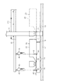
また、図4(b),(d),図11及び図12に示すように、支持装置11の両側の脚部181,182を構成する左右の構造材111に対してクランプ部材としての複数のクランプ金具40により下部搬送レール41の上部の被把持部43を把持連結する。この下部搬送レール41は、前記上部搬送レール32と同様に下部を開放するとともに、その開放部の両側にはレール面44が形成されている。また、下部搬送レール41は、前記構造材111に一対ずつ設けられる。各下部搬送レール41のレール面44には、電動ウィンチ45のモータを内蔵した本体46が上部の移動体47の上部のローラ471により前後方向に移動可能に支持される。電動ウィンチ45は、チェーン48の下端にフック49を有する。
Further, as shown in FIGS. 4B, 4D, 11 and 12, a plurality of clamp members as a clamp member with respect to the left and right
そして、図4(b),(d),図11及び図12に示すように、前記支持装置11の左右位置のフック49に走行駆動モータ22を有する大重量の走行装置20がその左右両側において吊り下げられて、ラップ側の脚部181に対応する所定位置まで搬送移動される。
4 (b), (d), FIG. 11 and FIG. 12, the heavy-
一方、走行装置20の搬送と相前後して、脚部181,182の下部に下部脚183が図示しないボルト及びナットにより連結される。そして、走行装置20がラップ側の脚部181の下部脚183にボルト50及び51により取り付けられる。
On the other hand, the
走行駆動モータ22を有しない軽量の走行装置21は、トンネル奥側である妻側の脚部182と対応する位置まで移動され、その走行装置21が妻側の脚部182の下部脚183に前記と同様にボルト50及びナット51により取り付けられる。この走行装置21の移動は、レッカーブームを用いてもよく、あるいは人力によりレール17上を走行されてもよい。
The
その後、ジャッキ16が収縮されて、そのジャッキ16が地面から離れ、図11に示すように、両走行装置20,21の車輪19がレール17上に載置される。これと前後して、下部搬送レール41が電動ウィンチ45等とともに取り外される。
Thereafter, the
そして、図5(b)に示すように、従来方法とは異なり、天井フォーム13を支持した状態の支持装置11はその位置で停止維持される。
次いで、図6(b),(d)及び図7(b),(d)に示すように、左右の上部搬送レール32側の電動ウィンチ35のフック39に既設のフォーム及び別のフォームとしてのサイドフォーム14が吊り下げられ、サイドフォーム14が人力により電動ウィンチ35とともに上部搬送レール32の延長方向に沿って1枚ずつ移動されて、天井フォーム13の下端に連結される。
Then, as shown in FIG. 5B, unlike the conventional method, the
Next, as shown in FIGS. 6B and 6D and FIGS. 7B and 7D, an existing foam and another foam are formed on the
さらに、図8(b),(d)及び図9(b),(d)に示すように、上部搬送レール32側の電動ウィンチ35のフック39に別のフォームとしてのインバートフォーム15が吊り下げられて、人力により1枚ずつ妻側に搬送移動されて、サイドフォーム14の下端に連結される。その後、上部搬送レール32は電動ウィンチ35等とともに取り外される。
Further, as shown in FIGS. 8B and 8D and FIGS. 9B and 9D, the
このようにして、コンクリート成形位置と対応する位置に本実施形態の型枠12が設置される。その後、レール17が上昇されて、型枠12のスキンプレート25と、トンネルTの内壁面との間にコンクリートCが打設される。打設されたコンクリートCが硬化されると、支持装置11が型枠12を支持した状態で、レール17上を妻側に移動されて、コンクリートCが打設され、これが繰り返される。
Thus, the
コンクリートCの硬化後の型枠12の解体においては、前記の組み上げ手順とはほぼ逆順の作業が実行される。ただし、この場合は、レール17は沈下されることなく、上昇位置に保持される。
In the dismantling of the
そして、本実施形態においては、以下の効果がある。
(1)走行駆動モータ22を有する走行装置20を下部搬送レール41に沿って脚部181の位置まで搬送移動できるため、走行装置20が大重量であっても、また、車輪19が一線上に並ぶ不安定構造であっても、レッカーブームWを用いることなく、走行装置20を安定状態で搬送して、脚部181に容易に連結できる。また、この逆順により、走行装置20を脚部181から容易に解体撤去できる。従って、従来方法と比較して工期短縮が可能になる。
The present embodiment has the following effects.
(1) Since the
(2)前記のように、下部搬送レール41がクランプ金具40の把持によって支持装置11の構造材111に支持されるため、搬送レール41を構造材111に対して強固に固定できるとともに、クランプ金具40を外すことにより、搬送レール41を容易に構造材111から解体撤去できる。
(2) Since the
(3)下部搬送レール41がクランプ金具40の把持によって支持装置11の構造材111に支持されるため、支持装置11に下部搬送レール41を支持するための改造を施す必要はなく、従来の支持装置11をそのまま使用できる。
(3) Since the
(4)図6(b),(d)及び図7(b),(d)に示すように、サイドフォーム14が支持装置11側部の上部搬送レール32に沿って吊り下げ状態で所定の組み付け位置まで搬送されて、天井フォーム13に連結される。従って、図6(a),(c)及び図7(a),(c)に示すように、レッカーブームWを用いてサイドフォーム14を搬送する従来方法と比較して、支持装置11をラップ側のコンクリート成形位置と対応する型枠組み立て位置と妻側の退避位置との間で移動させる手間は不要である。従って、作業が容易になるとともに、工期を短縮することが可能になる。
(4) As shown in FIGS. 6B and 6D and FIGS. 7B and 7D, the
(5)図8(b),(d)及び図9(b),(d)に示すように、サイドフォーム14と同様に、インバートフォーム15が支持装置11側部の上部搬送レール32に沿って吊り下げ状態で所定の組み付け位置まで搬送されて、サイドフォーム14に連結される。従って、図8(a),(c)及び図9(a),(c)に示すように、レッカーブームWを用いてインバートフォーム15を搬送する従来方法と比較して、支持装置11をコンクリート成形位置と退避位置との間で移動させる手間は必要がない。従って、工期を短縮することが可能になる。
(5) As shown in FIGS. 8B and 8D and FIGS. 9B and 9D, similarly to the
(6)図6(a),(c)及び図7(a),(c)や、図8(a),(c)及び図9(a),(c)に示すように、サイドフォーム14をトンネルTの内壁面に立てかけたり、インバートフォーム15を地面に寝かせたりする必要がないため、それらのフォーム14,15が汚れることを防止できる。従って、フォーム14,15の汚れ落としをするような必要はなく、工期を短縮することが可能になる。
(6) As shown in FIGS. 6 (a) and 6 (c) and FIGS. 7 (a) and 7 (c) and FIGS. 8 (a) and 8 (c) and FIGS. 9 (a) and 9 (c), the side foam Since it is not necessary to lean 14 on the inner wall surface of the tunnel T or to lay the
(7)上部搬送レール32がクランプ金具40によって天井フォーム13に固定されるため、クランプ金具40を脱着することにより、搬送レール32の取り付け、取り外しを容易に行なうことができる。また、上部搬送レール32が天井フォーム13に支持されるため、支持装置11に上部搬送レール32を支持するための改造を施す必要はない。
(7) Since the
(8)上部搬送レール32を天井フォーム13の下端に支持するため、その天井フォーム13の下側に連結されるサイドフォーム14やインバートフォーム15を搬送して、天井フォーム13の下側において容易に連結及び分解できる。
(8) In order to support the
(変更例)
・前記実施形態においては、駆動モータ22を有する走行装置20を下部搬送レール41に沿って搬送させるようにしたが、搬送レール41を後方へ延長させて、駆動モータ22が設けられてしない走行装置21を搬送できるようにすること。
(Example of change)
In the above embodiment, the
・前記実施形態では、搬送レールを支持装置11に支持したが、支持装置11上のフォームに支持すること。
-In the said embodiment, although the conveyance rail was supported by the
11…支持装置、12…型枠、19…車輪、20…走行装置、22…走行駆動モータ、37…移動体、40…クランプ金具、41…下部搬送レール、47…移動体、111…構造材、181…脚部、182…脚部。
DESCRIPTION OF
Claims (2)
前記支持装置の各脚部を構成する構造材のトンネル横断方向における両側に、クランプ部材によって着脱可能にトンネル長手方向に延びる搬送レールをそれぞれ設け、前記各搬送レール上を走行する移動体に設けられたウィンチに前記走行装置を吊り下げて前記支持装置の脚部の位置まで移動させ、その走行装置を前記脚部に連結するとともに、支持装置を下降させて、走行装置の車輪を地面のレール上に載せるコンクリート型枠支持装置における走行装置の取り付け方法。 In the mounting method of attaching a traveling device capable of traveling on a pair of rails laid on the ground of the tunnel to the legs of the supporting device on which the concrete formwork is mounted,
On both sides of the tunnel transverse structural member constituting each leg of the supporting device is provided with a transport rail extending removably tunnel longitudinal direction by clamping members respectively, provided on the moving body that travels on each conveyor rail The traveling device is suspended from the winch and moved to the position of the leg portion of the support device , the travel device is connected to the leg portion, and the support device is lowered so that the wheels of the traveling device are placed on the ground rail. A method for attaching a traveling device in a concrete formwork supporting device to be placed on a wall .
Priority Applications (1)
| Application Number | Priority Date | Filing Date | Title |
|---|---|---|---|
| JP2016004517A JP6468605B2 (en) | 2016-01-13 | 2016-01-13 | Method for attaching traveling device in concrete formwork support device |
Applications Claiming Priority (1)
| Application Number | Priority Date | Filing Date | Title |
|---|---|---|---|
| JP2016004517A JP6468605B2 (en) | 2016-01-13 | 2016-01-13 | Method for attaching traveling device in concrete formwork support device |
Publications (3)
| Publication Number | Publication Date |
|---|---|
| JP2017125326A JP2017125326A (en) | 2017-07-20 |
| JP2017125326A5 JP2017125326A5 (en) | 2018-02-15 |
| JP6468605B2 true JP6468605B2 (en) | 2019-02-13 |
Family
ID=59364944
Family Applications (1)
| Application Number | Title | Priority Date | Filing Date |
|---|---|---|---|
| JP2016004517A Active JP6468605B2 (en) | 2016-01-13 | 2016-01-13 | Method for attaching traveling device in concrete formwork support device |
Country Status (1)
| Country | Link |
|---|---|
| JP (1) | JP6468605B2 (en) |
Families Citing this family (2)
| Publication number | Priority date | Publication date | Assignee | Title |
|---|---|---|---|---|
| CN109538220B (en) * | 2018-09-30 | 2020-03-13 | 中铁二局集团有限公司 | Method for rail transportation and storage of double-shield TBM tunnel |
| JP7100896B2 (en) * | 2019-02-28 | 2022-07-14 | 有限会社 伊藤 | How to install the wheel unit in the center and the wheel unit guide device in the center |
Family Cites Families (14)
| Publication number | Priority date | Publication date | Assignee | Title |
|---|---|---|---|---|
| JPS5822636B2 (en) * | 1978-06-14 | 1983-05-10 | 佐賀工業株式会社 | tunnel digging equipment |
| JPS59126863A (en) * | 1983-01-06 | 1984-07-21 | 岡部株式会社 | Moving inner mold frame apparatus for tunnel or culvert |
| JPH0230899A (en) * | 1987-12-16 | 1990-02-01 | Kyowa Densetsu Kaisha Ltd | Movable formwork for tunnel covering work |
| JPH0639878B2 (en) * | 1988-08-25 | 1994-05-25 | 岐阜工業株式会社 | Moving mechanism for mobile formwork for lining |
| GB2262128B (en) * | 1991-12-06 | 1995-09-13 | John Gillespie | Tunnel shuttering |
| JP2570646Y2 (en) * | 1992-08-21 | 1998-05-06 | 石川島播磨重工業株式会社 | Line-off device for tracked bogies |
| JP2854227B2 (en) * | 1993-10-18 | 1999-02-03 | 株式会社熊谷組 | Form-mounted gantry jumbo |
| JP3103284B2 (en) * | 1994-12-16 | 2000-10-30 | 株式会社奥村組 | Tunnel excavation shearing gantry |
| JP3092907B2 (en) * | 1997-02-06 | 2000-09-25 | 西松建設株式会社 | Tunnel lining method and tunnel lining form device |
| JP3174037B2 (en) * | 1999-04-21 | 2001-06-11 | 大成建設株式会社 | Center trolley |
| JP2001020688A (en) * | 1999-07-06 | 2001-01-23 | Towa Kiden Kogyo Kk | Forms for tunnel |
| JP4023615B2 (en) * | 2004-03-29 | 2007-12-19 | 島工業株式会社 | Method for assembling formwork supporting apparatus for placing concrete in tunnel, method for disassembling formwork supporting apparatus for placing concrete in tunnel, elevating apparatus and elevating mechanism for formwork supporting apparatus for placing concrete in tunnel |
| JP6022207B2 (en) * | 2012-05-22 | 2016-11-09 | 前田建設工業株式会社 | Telescopic formwork device |
| JP6106539B2 (en) * | 2013-06-27 | 2017-04-05 | 株式会社Ihi | Construction method of cylindrical tank |
-
2016
- 2016-01-13 JP JP2016004517A patent/JP6468605B2/en active Active
Also Published As
| Publication number | Publication date |
|---|---|
| JP2017125326A (en) | 2017-07-20 |
Similar Documents
| Publication | Publication Date | Title |
|---|---|---|
| JP6468604B2 (en) | How to assemble concrete formwork | |
| JP3946342B2 (en) | Bridge erection device | |
| JP2017125325A5 (en) | ||
| JP5671373B2 (en) | Bridge removal method and new construction method | |
| JP4403579B2 (en) | Removal method of existing pier of overpass | |
| JP2018100564A (en) | Device and method of floor slab rebuilding | |
| JP5485076B2 (en) | Tunnel construction equipment and construction method | |
| JP4403051B2 (en) | Corrugated steel web bridge construction method | |
| JP2018145607A (en) | Work device and overhanging construction method | |
| JP2018105029A (en) | Movable type form device | |
| JP7100896B2 (en) | How to install the wheel unit in the center and the wheel unit guide device in the center | |
| JP6468605B2 (en) | Method for attaching traveling device in concrete formwork support device | |
| JP2020002563A (en) | Deck slab construction method | |
| JP2017125326A5 (en) | ||
| JP2017048635A (en) | Bridge disassembly method of using installation girder | |
| JP4361775B2 (en) | Bridge erection method and bridge erection device | |
| KR100454406B1 (en) | Method and apparatus for changing steel bridge of supporting rail into concrete bridge using temporary bent | |
| JP2006028881A (en) | Self-propelled pc floor slab erecting machine and pc floor slab erecting method | |
| JP5793062B2 (en) | Tunnel construction apparatus and tunnel construction method | |
| JP2019214858A (en) | Floor slab erection machine | |
| JP6529378B2 (en) | Invert construction method, tunnel construction method and Teruha crane for tunnel | |
| JP6776188B2 (en) | The erection machine and how to move the erection machine | |
| JP7008437B2 (en) | PCa floor slab transportation and installation jig for forklift trucks and PCa floor slab transportation and installation method using it | |
| JP5997656B2 (en) | Mobile formwork device for dam audit gallery and construction method of dam audit gallery | |
| JP2019019477A (en) | Floor slab replacement method and portal crane |
Legal Events
| Date | Code | Title | Description |
|---|---|---|---|
| A521 | Written amendment |
Free format text: JAPANESE INTERMEDIATE CODE: A523 Effective date: 20171227 |
|
| A621 | Written request for application examination |
Free format text: JAPANESE INTERMEDIATE CODE: A621 Effective date: 20171227 |
|
| A977 | Report on retrieval |
Free format text: JAPANESE INTERMEDIATE CODE: A971007 Effective date: 20180910 |
|
| A131 | Notification of reasons for refusal |
Free format text: JAPANESE INTERMEDIATE CODE: A131 Effective date: 20180918 |
|
| A521 | Written amendment |
Free format text: JAPANESE INTERMEDIATE CODE: A523 Effective date: 20181116 |
|
| TRDD | Decision of grant or rejection written | ||
| A01 | Written decision to grant a patent or to grant a registration (utility model) |
Free format text: JAPANESE INTERMEDIATE CODE: A01 Effective date: 20181211 |
|
| A61 | First payment of annual fees (during grant procedure) |
Free format text: JAPANESE INTERMEDIATE CODE: A61 Effective date: 20190110 |
|
| R150 | Certificate of patent or registration of utility model |
Ref document number: 6468605 Country of ref document: JP Free format text: JAPANESE INTERMEDIATE CODE: R150 |
|
| R250 | Receipt of annual fees |
Free format text: JAPANESE INTERMEDIATE CODE: R250 |