JP6466302B2 - Tablet printing apparatus and tablet printing method - Google Patents

Tablet printing apparatus and tablet printing method Download PDF

Info

Publication number
JP6466302B2
JP6466302B2 JP2015195432A JP2015195432A JP6466302B2 JP 6466302 B2 JP6466302 B2 JP 6466302B2 JP 2015195432 A JP2015195432 A JP 2015195432A JP 2015195432 A JP2015195432 A JP 2015195432A JP 6466302 B2 JP6466302 B2 JP 6466302B2
Authority
JP
Japan
Prior art keywords
tablet
unit
secant
processing
image
Prior art date
Legal status (The legal status is an assumption and is not a legal conclusion. Google has not performed a legal analysis and makes no representation as to the accuracy of the status listed.)
Active
Application number
JP2015195432A
Other languages
Japanese (ja)
Other versions
JP2017064213A (en
JP2017064213A5 (en
Inventor
順介 古水戸
順介 古水戸
Current Assignee (The listed assignees may be inaccurate. Google has not performed a legal analysis and makes no representation or warranty as to the accuracy of the list.)
Shibaura Mechatronics Corp
Original Assignee
Shibaura Mechatronics Corp
Priority date (The priority date is an assumption and is not a legal conclusion. Google has not performed a legal analysis and makes no representation as to the accuracy of the date listed.)
Filing date
Publication date
Application filed by Shibaura Mechatronics Corp filed Critical Shibaura Mechatronics Corp
Priority to JP2015195432A priority Critical patent/JP6466302B2/en
Publication of JP2017064213A publication Critical patent/JP2017064213A/en
Publication of JP2017064213A5 publication Critical patent/JP2017064213A5/ja
Application granted granted Critical
Publication of JP6466302B2 publication Critical patent/JP6466302B2/en
Active legal-status Critical Current
Anticipated expiration legal-status Critical

Links

Images

Description

本発明の実施形態は、錠剤印刷装置及び錠剤印刷方法に関する。   Embodiments described herein relate generally to a tablet printing apparatus and a tablet printing method.

通常、錠剤印刷装置は、錠剤を識別するため、錠剤の表面に文字(例えばアルファベット、片仮名、番号)やマーク(例えば記号、図形)などの識別情報を印刷する装置である。この錠剤印刷装置としては、識別情報変更の容易さや印刷品質の高さなどから、錠剤に非接触で印刷を行うインクジェット方式の錠剤印刷装置が開発されている。インクジェット方式の錠剤印刷装置は、搬送ベルトなどにより錠剤を搬送しながらその錠剤に向けてインク(例えば可食性インク)を吐出し、錠剤の表面に識別情報を印刷する。   Usually, a tablet printing apparatus is an apparatus that prints identification information such as characters (for example, alphabets, katakana and numbers) and marks (for example, symbols and figures) on the surface of a tablet in order to identify the tablets. As this tablet printing apparatus, an ink jet type tablet printing apparatus that performs printing in a non-contact manner on a tablet has been developed from the viewpoint of easy identification information change and high print quality. An ink jet type tablet printing apparatus discharges ink (for example, edible ink) toward a tablet while transporting the tablet by a transport belt or the like, and prints identification information on the surface of the tablet.

印刷対象となる錠剤としては、各種の錠剤が存在するが、その錠剤の中には表裏を有する錠剤がある。例えば、錠剤を割るための割線が片面に形成された錠剤においては、通常、割線の有る面が表とされ、割線の無い面が裏とされる。また、識別情報は、錠剤の両面(表裏)あるいは片面(表又は裏)に印刷される。   Various tablets exist as tablets to be printed, and some tablets have front and back surfaces. For example, in a tablet in which a secant for splitting a tablet is formed on one side, usually the side with the secant is the front and the side without the secant is the back. The identification information is printed on both sides (front and back) or one side (front or back) of the tablet.

錠剤は表裏が揃えられず搬送ベルト上に供給される場合がある。これは、錠剤の表裏を揃える工程を不要とし、生産性の低下やコストの上昇を抑えるためである。この場合、錠剤の表裏に応じた印刷を行うため、搬送ベルト上の錠剤の上面が表であるか否か、すなわち搬送ベルト上の錠剤の上面に割線が有るか否かを判定する必要がある。そこで、錠剤印刷装置は、カメラを用いて搬送ベルト上の錠剤の上面を撮影し、その画像を処理して割線の有無を判定する。   The tablets may be supplied on the conveyor belt without being aligned. This is because the process of aligning the front and back of the tablet is unnecessary, and the decrease in productivity and the increase in cost are suppressed. In this case, in order to perform printing according to the front and back of the tablet, it is necessary to determine whether or not the upper surface of the tablet on the transport belt is the front, that is, whether or not there is a secant on the upper surface of the tablet on the transport belt. . Therefore, the tablet printing apparatus photographs the upper surface of the tablet on the conveyance belt using a camera, and processes the image to determine the presence or absence of a secant line.

特開平7−81050号公報Japanese Patent Laid-Open No. 7-81050

しかしながら、前述のようにカメラを用いる場合には、搬送ベルト上の錠剤の上面を撮影し、その画像を処理して錠剤の表裏を判定する必要がある。このとき、カメラにより撮影された画像から割線の有無を判定する画像処理が必須となる。さらに、その他にも割線に係る画像処理が必要となり、複数の画像処理が実行されることになる。これらの画像処理は長い処理時間を要するため、錠剤に印刷を行う印刷効率又は錠剤の印刷品質を検査する検査効率が低下する。   However, when the camera is used as described above, it is necessary to photograph the upper surface of the tablet on the conveyor belt and process the image to determine the front and back of the tablet. At this time, image processing for determining the presence / absence of a secant from the image taken by the camera is essential. Furthermore, other image processing related to the secant line is required, and a plurality of image processing is executed. Since these image processes require a long processing time, the printing efficiency for printing on tablets or the inspection efficiency for inspecting the print quality of tablets decreases.

本発明が解決しようとする課題は、印刷効率又は検査効率を向上させることができる錠剤印刷装置及び錠剤印刷方法を提供することである。   The problem to be solved by the present invention is to provide a tablet printing apparatus and a tablet printing method capable of improving printing efficiency or inspection efficiency.

実施形態に係る錠剤印刷装置は、割線を一方の面に有する錠剤を搬送する搬送部と、搬送部により搬送される錠剤を撮像する撮像部と、撮像部よりも上流側にあって、撮像部により撮像される、錠剤の表面の形状に応じた信号を出力する検出部と、検出部の出力に基づいて錠剤の表面に割線が有るか否かを判定する判定部と、撮像部により得られた画像を処理する処理部と、搬送部により搬送される錠剤に印刷を行う印刷ヘッドと、を備え、処理部は、判定部により錠剤の表面に割線が有ると判定された場合には、撮像部により得られた画像に対して複数の画像処理を行い、判定部により錠剤の表面に割線が無いと判定された場合には、複数の画像処理から錠剤の割線に係る画像処理を省略して残りの画像処理を行う。 The tablet printing apparatus according to the embodiment includes a transport unit that transports a tablet having a secant on one surface, an image capturing unit that captures an image of the tablet transported by the transport unit, and an upstream side of the image capturing unit. Obtained by the detection unit that outputs a signal corresponding to the shape of the surface of the tablet, a determination unit that determines whether there is a secant on the surface of the tablet based on the output of the detection unit, and the imaging unit a processing unit for processing the image, and a print head for printing on the tablets being conveyed by the conveying unit, the processing unit, when it is determined that the dividing line is present on the surface of the tablet by the determination unit, imaging perform a plurality of image processing on the image obtained by parts, if the dividing line on the surface of the tablet is determined not by the determination unit, skip image processing according to the dividing line of the tablet from the plurality of image processing Perform the rest of the image processing.

実施形態に係る錠剤印刷方法は、割線を一方の面に有する錠剤を搬送する工程と、送される錠剤を撮像する工程と、錠剤を撮像する前に、撮像する工程により撮像される、錠剤の表面に割線が有るか否かを判定する工程と、撮像により得られた画像を処理する工程と、搬送される錠剤に印刷を行う工程と、を有し、画像を処理する工程では、錠剤の表面に割線が有ると判定された場合には、撮像により得られた画像に対して複数の画像処理を行い、錠剤の表面に割線が無いと判定された場合には、複数の画像処理から錠剤の割線に係る画像処理を省略して残りの画像処理を行う。 Tablet printing method according to the embodiment includes the steps of conveying the tablet having a secant on one surface, a step of taking the tablets fed transportable, before imaging the tablets are picked up by step of taking, tablets A step of determining whether or not there is a secant on the surface, a step of processing an image obtained by imaging, and a step of printing on a transported tablet. when it is determined on the surface of the dividing line is present, perform a plurality of image processing on the image obtained by the imaging, if it is determined that there is no secant to the surface of the tablet, from a plurality of image processing The remaining image processing is performed by omitting the image processing relating to the secant of the tablet.

本発明の実施形態によれば、印刷効率又は検査効率を向上させることができる。   According to the embodiment of the present invention, printing efficiency or inspection efficiency can be improved.

第1の実施形態に係る錠剤印刷装置の概略構成を示す図である。It is a figure which shows schematic structure of the tablet printing apparatus which concerns on 1st Embodiment. 第1の実施形態に係る錠剤印刷装置が備える第1の印刷部の一部を示す平面図である。It is a top view which shows a part of 1st printing part with which the tablet printing apparatus which concerns on 1st Embodiment is provided. 第1の実施形態に係る錠剤の表裏判定(割線の有無判定)を説明するための図である。It is a figure for demonstrating the front and back determination (presence / absence determination of a secant) of the tablet which concerns on 1st Embodiment. 第1の実施形態に係る錠剤の印刷処理の流れを示す第1のフローチャートである。It is a 1st flowchart which shows the flow of the printing process of the tablet which concerns on 1st Embodiment. 第1の実施形態に係る錠剤の検査処理の流れを示す第2のフローチャートである。It is a 2nd flowchart which shows the flow of the test | inspection process of the tablet which concerns on 1st Embodiment. 第2の実施形態に係る錠剤印刷装置の概略構成を示す図である。It is a figure which shows schematic structure of the tablet printing apparatus which concerns on 2nd Embodiment. 第2の実施形態に係る錠剤の印刷処理の流れを示すフローチャートである。It is a flowchart which shows the flow of the printing process of the tablet which concerns on 2nd Embodiment.

(第1の実施形態)
第1の実施形態について図1から図5を参照して説明する。
(First embodiment)
A first embodiment will be described with reference to FIGS. 1 to 5.

(基本構成)
図1に示すように、第1の実施形態に係る錠剤印刷装置1は、錠剤供給部10と、第1の印刷部20と、第2の印刷部30と、錠剤収容部40と、制御部50とを備えている。なお、第1の印刷部20と第2の印刷部30は基本的に同じ構造である。
(Basic configuration)
As shown in FIG. 1, the tablet printing apparatus 1 according to the first embodiment includes a tablet supply unit 10, a first printing unit 20, a second printing unit 30, a tablet storage unit 40, and a control unit. 50. The first printing unit 20 and the second printing unit 30 have basically the same structure.

錠剤供給部10は、ホッパー11、整列フィーダ12及び受け渡しフィーダ13を有している。この錠剤供給部10は、印刷対象となる錠剤Tを第1の印刷部20に供給することが可能に構成されており、第1の印刷部20の一端側に設けられている。ホッパー11は、多数の錠剤Tを収容し、整列フィーダ12に錠剤Tを順次供給する。整列フィーダ12は、供給された錠剤Tを一列に整列し、受け渡しフィーダ13に向けて搬送する。受け渡しフィーダ13は、整列フィーダ12上の錠剤Tを順次吸引して第1の印刷部20まで一列に搬送し、第1の印刷部20に供給する。この錠剤供給部10は制御部50に電気的に接続されており、その駆動が制御部50により制御される。なお、整列フィーダ12及び受け渡しフィーダ13としては、例えば、ベルト搬送機構などを用いることが可能である。   The tablet supply unit 10 includes a hopper 11, an alignment feeder 12, and a delivery feeder 13. The tablet supply unit 10 is configured to be able to supply tablets T to be printed to the first printing unit 20, and is provided on one end side of the first printing unit 20. The hopper 11 accommodates a large number of tablets T and sequentially supplies the tablets T to the alignment feeder 12. The alignment feeder 12 aligns the supplied tablets T in a line and conveys them toward the delivery feeder 13. The delivery feeder 13 sequentially sucks the tablets T on the alignment feeder 12 and conveys them to the first printing unit 20 in a row and supplies them to the first printing unit 20. The tablet supply unit 10 is electrically connected to the control unit 50, and the driving thereof is controlled by the control unit 50. In addition, as the alignment feeder 12 and the delivery feeder 13, for example, a belt conveyance mechanism or the like can be used.

ここで、ホッパー11は、錠剤Tの供給時、錠剤Tの表裏を無視して整列フィーダ12に錠剤Tを供給する。このため、整列フィーダ12上には表の錠剤Tと裏の錠剤Tが混在することになる。錠剤Tの表は割線(例えば溝部)の有る面であり、錠剤Tの裏は割線の無い面である。   Here, when supplying the tablet T, the hopper 11 ignores the front and back of the tablet T and supplies the tablet T to the alignment feeder 12. For this reason, the front tablet T and the back tablet T are mixed on the alignment feeder 12. The front of the tablet T is a surface having a secant (for example, a groove), and the back of the tablet T is a surface having no secant.

第1の印刷部20は、搬送部21と、検出部22と、印刷用の撮像部(第1の撮像部)23と、印刷ヘッド24と、検査用の撮像部(第2の撮像部)25と、乾燥部26と、回収部27とを備えている。   The first printing unit 20 includes a transport unit 21, a detection unit 22, an imaging unit for printing (first imaging unit) 23, a print head 24, and an imaging unit for inspection (second imaging unit). 25, a drying unit 26, and a recovery unit 27.

搬送部21は、搬送ベルト21a、第1のプーリ21b、第2のプーリ21c及びモータ21dを有している。搬送ベルト21aは、無端状に形成されており、第1のプーリ21b及び第2のプーリ21cに架け渡されている。第1のプーリ21bは、駆動源となるモータ21dに連結されており、駆動プーリとして機能する。第2のプーリ21cは従動プーリとして機能する。モータ21dは制御部50に電気的に接続されており、その駆動が制御部50により制御される。   The transport unit 21 includes a transport belt 21a, a first pulley 21b, a second pulley 21c, and a motor 21d. The conveyor belt 21a is formed in an endless shape and is stretched over the first pulley 21b and the second pulley 21c. The first pulley 21b is connected to a motor 21d serving as a drive source and functions as a drive pulley. The second pulley 21c functions as a driven pulley. The motor 21 d is electrically connected to the control unit 50, and its driving is controlled by the control unit 50.

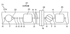
このような搬送部21は、モータ21dによる第1のプーリ21bの回転によって第2のプーリ21cと共に搬送ベルト21aを回転させ、搬送ベルト21a上の錠剤Tを図1中の矢印A1の方向(搬送方向A1)に搬送する。搬送ベルト21aには、図2に示すように、複数の吸引孔Hが搬送方向A1に沿って一列に形成されている。各吸引孔Hは吸引チャンバを介して吸気装置(いずれも図示せず)に接続されており、吸気装置(例えば吸引ポンプ)の駆動により吸引力を得る。吸引孔H上に供給された錠剤Tは、その吸引孔Hによる吸引によって搬送ベルト21a上に保持される。   Such a transport unit 21 rotates the transport belt 21a together with the second pulley 21c by the rotation of the first pulley 21b by the motor 21d, and the tablet T on the transport belt 21a is transported in the direction indicated by the arrow A1 in FIG. Transport in direction A1). As shown in FIG. 2, a plurality of suction holes H are formed in the transport belt 21a in a line along the transport direction A1. Each suction hole H is connected to an intake device (not shown) via a suction chamber, and obtains suction force by driving the intake device (for example, a suction pump). The tablet T supplied onto the suction hole H is held on the transport belt 21 a by suction through the suction hole H.

検出部22は、錠剤Tが錠剤供給部10により供給される位置より搬送方向A1の下流側に位置付けられ、搬送ベルト21aの上方に設けられている。検出部22としては、例えば、反射型レーザセンサなど各種のレーザセンサ(レーザ変位計)を用いることが可能である。また、レーザ光のビーム形状としては、スポットやラインなど各種の形状を用いることが可能である。そして、搬送ベルト21aの上方に設けられ搬送ベルト21aに対向する検出部22は、搬送ベルト21aにより搬送される錠剤Tの上面(例えば上面のほぼ中央)にレーザ光を照射することが可能な位置に配置されている。   The detection unit 22 is positioned on the downstream side in the transport direction A1 from the position where the tablet T is supplied by the tablet supply unit 10, and is provided above the transport belt 21a. As the detection unit 22, for example, various laser sensors (laser displacement meters) such as a reflection type laser sensor can be used. Various shapes such as spots and lines can be used as the beam shape of the laser light. And the detection part 22 provided above the conveyance belt 21a and facing the conveyance belt 21a can irradiate a laser beam on the upper surface (for example, substantially the center of the upper surface) of the tablet T conveyed by the conveyance belt 21a. Is arranged.

このような検出部22は、搬送ベルト21a上の錠剤Tに向けてレーザ光を照射し、錠剤Tにより反射されたレーザ光(反射光)を受光し、レーザ光の反射強度を制御部50に送信する。このレーザ光の反射強度は、搬送ベルト21aの表面又はその搬送ベルト21a上の錠剤Tの上面と、検出部22との離間距離を示す情報となる。また、検出部22は、レーザ光の投受光によって搬送ベルト21a上の錠剤Tの位置(搬送方向A1の位置)も検出し、下流に位置する各装置のトリガーセンサとしても機能する。検出部22は制御部50に電気的に接続されており、制御部50に搬送ベルト21a上の錠剤Tの位置の情報(位置情報)やレーザ光の反射強度の情報(反射強度情報)を送信する。   Such a detection part 22 irradiates a laser beam toward the tablet T on the transport belt 21a, receives the laser light (reflected light) reflected by the tablet T, and sets the reflection intensity of the laser light to the control part 50. Send. The reflection intensity of the laser light is information indicating the separation distance between the surface of the conveyor belt 21 a or the upper surface of the tablet T on the conveyor belt 21 a and the detection unit 22. The detection unit 22 also detects the position of the tablet T on the transport belt 21a (position in the transport direction A1) by projecting and receiving laser light, and also functions as a trigger sensor for each device located downstream. The detection unit 22 is electrically connected to the control unit 50, and transmits to the control unit 50 information on the position of the tablet T on the conveyor belt 21a (position information) and information on the reflection intensity of the laser beam (reflection intensity information). To do.

第1の撮像部23は、検出部22より搬送方向A1の下流側に位置付けられ、搬送ベルト21aの上方に設けられている。この第1の撮像部23は、前述の錠剤Tの位置情報に基づくタイミングで撮像を行い、錠剤Tの上面を含む画像(印刷用の画像)を取得し、取得した画像を制御部50に送信する。第1の撮像部23としては、例えば、CCD(電荷結合素子)やCMOS(相補型金属酸化膜半導体)などの撮像素子を有する各種の撮像部を用いることが可能である。第1の撮像部23は制御部50に電気的に接続されており、その駆動が制御部50により制御される。なお、必要に応じて撮像用の照明も設けられている。   The first imaging unit 23 is positioned downstream of the detection unit 22 in the transport direction A1 and is provided above the transport belt 21a. The first imaging unit 23 performs imaging at a timing based on the position information of the tablet T described above, acquires an image including the upper surface of the tablet T (image for printing), and transmits the acquired image to the control unit 50. To do. As the first imaging unit 23, for example, various imaging units having an imaging element such as a CCD (Charge Coupled Device) or a CMOS (Complementary Metal Oxide Semiconductor) can be used. The first imaging unit 23 is electrically connected to the control unit 50, and its driving is controlled by the control unit 50. Note that illumination for imaging is also provided as necessary.

印刷ヘッド24は、複数のノズルN(図2参照)から個別にインクを吐出するインクジェット方式の印刷ヘッドである。この印刷ヘッド24は、撮像部23より搬送方向A1の下流側に位置付けられ、各ノズルNが並ぶノズル整列方向が水平面内で搬送方向A1と交わるように(例えば直交するように)搬送ベルト21aの上方に設けられている。印刷ヘッド24としては、例えば、圧電素子、発熱素子又は磁歪素子などの駆動素子を有する各種のインクジェット方式の印刷ヘッドを用いることが可能である。印刷ヘッド24は制御部50に電気的に接続されており、その駆動が制御部50により制御される。   The print head 24 is an inkjet print head that individually ejects ink from a plurality of nozzles N (see FIG. 2). The print head 24 is positioned downstream of the imaging unit 23 in the transport direction A1, and the transport belt 21a is arranged such that the nozzle alignment direction in which the nozzles N are aligned intersects the transport direction A1 in the horizontal plane (for example, orthogonal). It is provided above. As the print head 24, for example, various ink jet print heads having drive elements such as piezoelectric elements, heat generating elements, or magnetostrictive elements can be used. The print head 24 is electrically connected to the control unit 50, and its driving is controlled by the control unit 50.

第2の撮像部25は、印刷ヘッド24より搬送方向A1の下流側に位置付けられ、搬送ベルト21aの上方に設けられている。この第2の撮像部25は、前述の錠剤Tの位置情報に基づくタイミングで撮像を行い、印刷済の錠剤Tの上面を含む画像(検査用の画像)を取得し、取得した画像を制御部50に送信する。第2の撮像部25としては、例えば、CCDやCMOSなどの撮像素子を有する各種の撮像部を用いることが可能である。第2の撮像部25は制御部50に電気的に接続されており、その駆動が制御部50により制御される。なお、必要に応じて撮像用の照明も設けられている。   The second imaging unit 25 is positioned on the downstream side in the transport direction A1 from the print head 24, and is provided above the transport belt 21a. The second imaging unit 25 performs imaging at a timing based on the position information of the tablet T described above, acquires an image (inspection image) including the upper surface of the printed tablet T, and uses the acquired image as a control unit. 50. As the second imaging unit 25, for example, various imaging units having an imaging element such as a CCD or a CMOS can be used. The second imaging unit 25 is electrically connected to the control unit 50, and its driving is controlled by the control unit 50. Note that illumination for imaging is also provided as necessary.

乾燥部26は、撮像部25より搬送方向A1の下流側に位置付けられ、搬送ベルト21aの下方、すなわち搬送部21の下方に設けられている。この乾燥部26は、搬送ベルト21a上の個々の錠剤Tに塗布されたインクを乾燥させる。乾燥部26としては、例えば、放射熱により乾燥対象を乾燥させるヒータ、あるいは、温風や熱風により乾燥対象を乾燥させる送風機など各種の乾燥部を用いることが可能である。乾燥部26は制御部50に電気的に接続されており、その駆動が制御部50により制御される。   The drying unit 26 is positioned downstream of the imaging unit 25 in the transport direction A1, and is provided below the transport belt 21a, that is, below the transport unit 21. The drying unit 26 dries the ink applied to each tablet T on the transport belt 21a. As the drying unit 26, it is possible to use various types of drying units such as a heater that dries an object to be dried by radiant heat or a blower that dries an object to be dried by warm air or hot air. The drying unit 26 is electrically connected to the control unit 50, and its driving is controlled by the control unit 50.

回収部27は、乾燥部26より搬送方向A1の下流側に位置付けられ、搬送ベルト21aの下方、すなわち搬送部21の下方に設けられている。この回収部27用の噴射ノズル27aは、回収部27に搬送ベルト21aを挟んで対向させて搬送部21内に設けられている。この噴射ノズル27aは、搬送ベルト21a上の錠剤T(不良品の錠剤T)に気体(例えばエア)を吹き付け、搬送ベルト21a上から錠剤Tを落下させる。このため、回収部27は、その落下する錠剤Tを受けて回収することが可能に形成されている。噴射ノズル27aは制御部50に電気的に接続されており、その駆動が制御部50により制御される。   The collection unit 27 is positioned downstream of the drying unit 26 in the conveyance direction A1, and is provided below the conveyance belt 21a, that is, below the conveyance unit 21. The ejection nozzle 27a for the collection unit 27 is provided in the conveyance unit 21 so as to face the collection unit 27 with the conveyance belt 21a interposed therebetween. The spray nozzle 27a sprays gas (for example, air) onto the tablet T (defective product tablet T) on the transport belt 21a, and drops the tablet T from the transport belt 21a. For this reason, the collection | recovery part 27 is formed so that it can receive and collect | recover the tablet T which falls. The injection nozzle 27 a is electrically connected to the control unit 50, and its driving is controlled by the control unit 50.

なお、前述の噴射ノズル27aにより落とされなかった錠剤T(良品の錠剤T)は、搬送ベルト21aの移動に伴って搬送され、搬送ベルト21aにおける第1のプーリ21c側の端部付近に位置する。この位置で吸引作用が錠剤Tに働かなくなり、錠剤Tは搬送ベルト21aに保持された状態から解放され、第1の印刷部20から第2の印刷部30に受け渡される。   The tablet T (good tablet T) that has not been dropped by the injection nozzle 27a is transported as the transport belt 21a moves, and is located near the end of the transport belt 21a on the first pulley 21c side. . At this position, the suction action does not act on the tablet T, and the tablet T is released from the state held by the transport belt 21 a and is transferred from the first printing unit 20 to the second printing unit 30.

第2の印刷部30は、前述の第1の印刷部20と同様、搬送部31と、検出部32と、印刷用の撮像部(第1の撮像部)33と、印刷ヘッド34と、検査用の撮像部(第2の撮像部)35と、乾燥部36と、回収部37とを備えている。搬送部31は、搬送ベルト31a、第1のプーリ31b、第2のプーリ31c及びモータ31dを有している。また、回収部37用の噴射ノズル37aも設けられている。各部の説明は前述の第1の印刷部20と同様となるため省略する。なお、第2の印刷部30の搬送方向は図1中の矢印A2の方向(搬送方向A2)である。   Similar to the first printing unit 20 described above, the second printing unit 30 includes a transport unit 31, a detection unit 32, a printing imaging unit (first imaging unit) 33, a print head 34, and an inspection. An imaging unit (second imaging unit) 35, a drying unit 36, and a collection unit 37. The transport unit 31 includes a transport belt 31a, a first pulley 31b, a second pulley 31c, and a motor 31d. An injection nozzle 37a for the collection unit 37 is also provided. Since the description of each part is the same as that of the first printing part 20 described above, a description thereof will be omitted. The transport direction of the second printing unit 30 is the direction of the arrow A2 in FIG. 1 (transport direction A2).

錠剤収容部40は、第2の印刷部30の回収部37より搬送方向A2の下流側に位置付けられ、搬送部31の端部、すなわち搬送ベルト31aにおける第2のプーリ31c側の端部に設けられている。この錠剤収容部40は、搬送ベルト31aによる保持から解放されて落下する錠剤Tを順次受けて回収することが可能に構成されている。なお、搬送部31は、搬送ベルト31a上の個々の錠剤Tが所望の位置、例えば、搬送ベルト31aにおける搬送方向A1の下流側の端部に到達した場合に錠剤Tの保持を解除する。   The tablet storage unit 40 is positioned downstream of the collection unit 37 of the second printing unit 30 in the transport direction A2, and is provided at the end of the transport unit 31, that is, the end of the transport belt 31a on the second pulley 31c side. It has been. The tablet container 40 is configured to be able to sequentially receive and collect the tablets T that are released from being held by the transport belt 31a and fall. In addition, the conveyance part 31 cancel | releases holding | maintenance of the tablet T when each tablet T on the conveyance belt 31a reaches | attains a desired position, for example, the edge part of the conveyance direction A1 in the conveyance belt 31a downstream.

制御部50は、判定部51、画像処理部52、印刷処理部53、検査処理部54及び記憶部55を備えている。判定部51は各種の判定を行う。画像処理部52は画像を処理する。印刷処理部53は印刷に係る処理を行う。検査処理部54は検査に係る処理を行う。記憶部55は処理情報や各種プログラムなどの各種情報を記憶する。このような制御部50は、第1の印刷部20や第2の印刷部30の個々の検出部22、32から送信される錠剤Tの位置情報やレーザ光の反射強度、第1の印刷部20や第2の印刷部30の個々の撮像部23、25、33、35から送信される画像などを受信する。   The control unit 50 includes a determination unit 51, an image processing unit 52, a print processing unit 53, an inspection processing unit 54, and a storage unit 55. The determination unit 51 performs various determinations. The image processing unit 52 processes an image. The print processing unit 53 performs processing related to printing. The inspection processing unit 54 performs processing related to inspection. The storage unit 55 stores various information such as processing information and various programs. Such a control unit 50 includes the position information of the tablet T and the reflection intensity of the laser beam transmitted from the individual detection units 22 and 32 of the first printing unit 20 and the second printing unit 30, and the first printing unit. 20 and images transmitted from the individual imaging units 23, 25, 33, and 35 of the second printing unit 30 are received.

(錠剤Tの表裏判定)
判定部51は、検出部22、32から送信されたレーザ光の反射強度情報に基づいて錠剤Tの表裏判定、すなわち錠剤Tの上面に割線が有るか否か(錠剤Tの上面における割線の有無)を判定する。つまり、錠剤Tの上面に割線が有れば表、割線が無ければ裏と判定することになる。この判定の結果が表裏情報であり、記憶部55に保存される。なお、表裏情報としては、単に割線の有無情報でも良い。検出部22及び32は基本的に同じであるため、代表して検出部22について説明する。
(Determination of front and back of tablet T)
The determination unit 51 determines the front and back of the tablet T based on the reflection intensity information of the laser light transmitted from the detection units 22 and 32, that is, whether or not there is a secant on the upper surface of the tablet T (whether or not there is a secant on the upper surface of the tablet T). ). That is, if there is a secant on the upper surface of the tablet T, it is determined to be a front side, and if there is no secant, it is determined to be the back side. The result of this determination is front / back information, which is stored in the storage unit 55. The front / back information may simply be secant presence / absence information. Since the detection units 22 and 32 are basically the same, the detection unit 22 will be described as a representative.

図3に示すように、検出部22のレーザスポットS1は、相対移動する錠剤Tの上面のほぼ中心を通過する。各錠剤Tは自身の中心が所定ライン上に位置して一列の状態で搬送されるが、錠剤Tの中にはその中心が所定ライン上からずれているものがある。ただし、このずれ量は小さいため、各錠剤Tはほぼ一列で搬送されることになる。   As shown in FIG. 3, the laser spot S <b> 1 of the detection unit 22 passes through almost the center of the upper surface of the relatively moving tablet T. Each tablet T is conveyed in a row with its center positioned on a predetermined line, but some tablets T have their centers shifted from the predetermined line. However, since this shift amount is small, the tablets T are transported in almost one row.

検出部22の出力(レーザ光の反射強度)B1は、検出部22と、搬送ベルト21aの表面又は搬送ベルト21a上の錠剤Tの上面との離間距離に応じて変化する。例えば、出力B1は、搬送ベルト21a上に錠剤Tが存在しない場合、すなわちレーザスポットS1が搬送ベルト21aの表面に当たると反射強度b1となる。また、出力B1は、レーザスポットS1が搬送ベルト21a上の錠剤Tの割線(例えば溝部)内の上面に当たると反射強度b2となり、搬送ベルト21a上の錠剤Tの割線以外の上面に当たると反射強度b3となる(b1<b2<b3)。このとき、出力B1は、搬送ベルト21a上の錠剤Tの高さの変化に応じて変わる。換言すると、検出部22は搬送ベルト21a上で搬送されている錠剤Tの高さを検出することになる。すなわち、搬送ベルト21a上を搬送される錠剤Tが検出部22直下を通過することに応じて、錠剤TがレーザスポットS1に到達すると反射強度b1から反射強度b2あるいは反射強度b3の出力がなされ(出力B1の立ち上がり)、錠剤TがレーザスポットS1を通過すると反射強度b1に戻る(出力B1の立下り)ことが繰り返される。よって、この出力B1の立ち上がりから立下りまでが錠剤Tということになる。   The output (laser beam reflection intensity) B1 of the detection unit 22 changes according to the separation distance between the detection unit 22 and the surface of the transport belt 21a or the upper surface of the tablet T on the transport belt 21a. For example, the output B1 becomes the reflection intensity b1 when the tablet T is not present on the transport belt 21a, that is, when the laser spot S1 hits the surface of the transport belt 21a. Further, the output B1 is reflected intensity b2 when the laser spot S1 hits the upper surface in the dividing line (for example, groove) of the tablet T on the conveying belt 21a, and reflected intensity b3 when it hits the upper surface other than the dividing line of the tablet T on the conveying belt 21a. (B1 <b2 <b3). At this time, the output B1 changes according to the change in the height of the tablet T on the transport belt 21a. In other words, the detection unit 22 detects the height of the tablet T being transported on the transport belt 21a. That is, when the tablet T transported on the transport belt 21a passes directly below the detection unit 22, when the tablet T reaches the laser spot S1, the reflection intensity b2 or the reflection intensity b3 is output (from the reflection intensity b1). When the tablet T passes the laser spot S1, the output intensity B1 is repeatedly returned (the output B1 falls). Therefore, the tablet T is from the rise to the fall of the output B1.

判定部51は、前述の検出部22の出力B1に基づいて、搬送ベルト21a上の錠剤Tの上面に割線が有るか否かを判定し、また、錠剤Tが所定位置に到達したか否かを判定する。例えば、判定部51は、出力B1が前述の立ち上がりから立下りの間で反射強度b2が生じた場合、搬送ベルト21a上の錠剤Tの上面に割線が有ると判定し、その他の場合、搬送ベルト21a上の錠剤Tの上面に割線が無いと判定する。また、他の判定例として、判定部51は、反射強度b1と反射強度b2との間の所定値を第1の閾値(b1<第1の閾値<b2)とし、反射強度b2と反射強度b3との間の所定値を第2の閾値として(b2<第2の閾値<b3)、出力B1が前述の立ち上がりから立下りの間で第1の閾値より大きく第2の閾値より小さい値が生じる場合、搬送ベルト21a上の錠剤Tの上面に割線が有ると判定し、その他の場合、搬送ベルト21a上の錠剤Tの上面に割線が無いと判定することも可能である。また、判定部51は、出力B1が反射強度b1より大きくなると(反射強度信号の立ち上がり)、錠剤Tが所定位置に到達したと判定する(位置検出)。   The determination unit 51 determines whether or not there is a secant on the upper surface of the tablet T on the transport belt 21a based on the output B1 of the detection unit 22 described above, and whether or not the tablet T has reached a predetermined position. Determine. For example, the determination unit 51 determines that there is a secant on the upper surface of the tablet T on the transport belt 21a when the reflection intensity b2 occurs between the rising and falling of the output B1, and in other cases, the transport belt It determines with there being no secant on the upper surface of the tablet T on 21a. As another determination example, the determination unit 51 sets a predetermined value between the reflection intensity b1 and the reflection intensity b2 as a first threshold (b1 <first threshold <b2), and the reflection intensity b2 and the reflection intensity b3. As a second threshold value (b2 <second threshold value <b3), the output B1 is larger than the first threshold value and smaller than the second threshold value between the rising edge and the falling edge. In this case, it may be determined that there is a secant on the upper surface of the tablet T on the transport belt 21a, and in other cases, it may be determined that there is no secant on the upper surface of the tablet T on the transport belt 21a. Further, the determination unit 51 determines that the tablet T has reached a predetermined position (position detection) when the output B1 becomes larger than the reflection intensity b1 (rising edge of the reflection intensity signal).

(印刷及び検査処理)
次に、前述の錠剤印刷装置1が行う印刷及び検査処理(印刷及び検査工程)について図4及び図5を参照して説明する。図4は第1の印刷部20の印刷処理の流れを示し、図5は第1の印刷部20の検査処理の流れを示す。なお、第2の印刷部30の印刷及び検査処理の流れは第1の印刷部20と同様であるため、その説明を省略する。
(Printing and inspection processing)
Next, printing and inspection processing (printing and inspection process) performed by the tablet printing apparatus 1 described above will be described with reference to FIGS. 4 and 5. 4 shows the flow of the printing process of the first printing unit 20, and FIG. 5 shows the flow of the inspection process of the first printing unit 20. Note that the flow of printing and inspection processing by the second printing unit 30 is the same as that of the first printing unit 20, and thus description thereof is omitted.

図4に示すように、ステップS1において、錠剤Tがホッパー11から整列フィーダ12に順次供給され始め、整列フィーダ12により一列に並べられる。一列に移動する錠剤Tは受け渡しフィーダ13により搬送ベルト21aに順次供給される。搬送ベルト21aは、モータ21dによる第1のプーリ21b及び第2のプーリ21cの回転によって搬送方向A1に回転している。このため、搬送ベルト21a上に供給された錠剤Tは搬送ベルト21a上で一列に並んで搬送されていく。なお、搬送ベルト31aもモータ31dによる第1のプーリ31b及び第2のプーリ31cの回転によって搬送方向A2に回転している。   As shown in FIG. 4, in step S <b> 1, the tablets T start to be sequentially supplied from the hopper 11 to the alignment feeder 12, and are aligned in a line by the alignment feeder 12. The tablets T moving in a row are sequentially supplied to the transport belt 21a by the delivery feeder 13. The transport belt 21a is rotated in the transport direction A1 by the rotation of the first pulley 21b and the second pulley 21c by the motor 21d. For this reason, the tablets T supplied onto the conveyor belt 21a are conveyed in a line on the conveyor belt 21a. The transport belt 31a is also rotated in the transport direction A2 by the rotation of the first pulley 31b and the second pulley 31c by the motor 31d.

ステップS2において、搬送ベルト21a上の錠剤Tが検出部22によって検出される(センサ1)。これにより、錠剤Tの位置情報(搬送方向A1の位置)やレーザ光の反射強度情報が取得され、制御部50に入力される。さらに、レーザ光の反射強度情報に基づいて搬送ベルト21a上の錠剤Tの上面に割線が有るか否かが判定部51により判定される(表裏情報)。これら錠剤Tの位置情報及び表裏情報は記憶部55に保存されて後処理で用いられる。   In step S2, the tablet T on the transport belt 21a is detected by the detection unit 22 (sensor 1). Thereby, the position information of the tablet T (position in the transport direction A1) and the reflection intensity information of the laser beam are acquired and input to the control unit 50. Further, the determination unit 51 determines whether or not there is a secant on the upper surface of the tablet T on the transport belt 21a based on the reflection intensity information of the laser light (front / back information). The position information and front / back information of the tablets T are stored in the storage unit 55 and used in post-processing.

ステップS3において、搬送ベルト21a上の錠剤Tが第1の撮像部23によって撮像される(カメラ1)。錠剤Tの上面は、前述の錠剤Tの位置情報に基づくタイミングで第1の撮像部23により撮像され、撮像された画像は制御部50に送信される。   In step S3, the tablet T on the transport belt 21a is imaged by the first imaging unit 23 (camera 1). The upper surface of the tablet T is captured by the first imaging unit 23 at a timing based on the position information of the tablet T described above, and the captured image is transmitted to the control unit 50.

ステップS4において、錠剤Tの重心判定が画像処理部52により行われる。錠剤Tの重心判定では、第1の撮像部23により撮像された画像から外縁部分あるいは全体部分が画像処理により抽出され、錠剤Tの重心が求められる。そして、求められた重心と基準座標中心とのオフセット量(位置情報)が算出される。このオフセット量は適宜、記憶部55に保存される。   In step S <b> 4, the center of gravity of the tablet T is determined by the image processing unit 52. In determining the center of gravity of the tablet T, the outer edge portion or the entire portion is extracted from the image captured by the first imaging unit 23 by image processing, and the center of gravity of the tablet T is obtained. Then, an offset amount (position information) between the obtained center of gravity and the center of the reference coordinate is calculated. This offset amount is stored in the storage unit 55 as appropriate.

ステップS5において、前述の記憶部55に保存された表裏情報に基づき、搬送ベルト21a上の錠剤Tが表であるか否かが印刷処理部53により判断される。錠剤Tが表であると判断された場合(YES)、処理はステップS6に進められる。一方、錠剤Tが裏であると判断された場合には(NO)、処理はステップS9に進められる。これにより、錠剤Tが裏である場合、ステップS6の割線検出処理及びステップS7の割線角度判定処理が省略される。   In step S5, based on the front / back information stored in the storage unit 55, the print processing unit 53 determines whether or not the tablets T on the transport belt 21a are front. If it is determined that the tablet T is a table (YES), the process proceeds to step S6. On the other hand, when it is determined that the tablet T is the back side (NO), the process proceeds to step S9. Thereby, when the tablet T is the back, the secant detection process of step S6 and the secant angle determination process of step S7 are omitted.

ステップS6において、錠剤Tの割線検出が画像処理部52により行われる。錠剤Tの割線検出では、基準座標中心部分(重心部分)近傍で割線に相当するパターンを把握するため、特徴抽出処理及びパターンマッチング処理が画像処理により行われる。   In step S <b> 6, the secant detection of the tablet T is performed by the image processing unit 52. In the detection of the dividing line of the tablet T, a feature extraction process and a pattern matching process are performed by image processing in order to grasp a pattern corresponding to the dividing line in the vicinity of the center portion (center of gravity) of the reference coordinates.

ステップS7において、錠剤Tの割線角度判定が画像処理部52により行われる。割線角度判定では、前述の特徴抽出処理により抽出された割線部分抽出画像から、割線と基準座標との角度が画像処理により算出される。この角度情報は適宜、記憶部55に保存される。   In step S <b> 7, the dividing angle determination of the tablet T is performed by the image processing unit 52. In the secant angle determination, the angle between the secant and the reference coordinates is calculated by image processing from the secant portion partial extracted image extracted by the above feature extraction processing. This angle information is stored in the storage unit 55 as appropriate.

ステップS8において、塗布位置の算出及び表印刷パターンデータの生成が印刷処理部53により行われる。前述のオフセット量に基づいて塗布位置が算出され、前述の割線の角度情報に基づいて表印刷パターンデータが生成される。例えば、前述の割線の角度情報に基づき、所定角度(例えば1度)ごとの表印刷パターンデータから最適なパターンデータ(例えば、識別情報が割線に平行となるパターンデータ)が表印刷パターンデータとして選択される。所定角度ごとの表印刷パターンデータは記憶部55に予め保存されており、記憶部55から読み出されて用いられる。   In step S <b> 8, the application position calculation and front print pattern data generation are performed by the print processing unit 53. The application position is calculated based on the offset amount described above, and the front print pattern data is generated based on the angle information of the secant. For example, based on the above-mentioned angle information of the dividing line, the optimum pattern data (for example, pattern data whose identification information is parallel to the dividing line) is selected as the table printing pattern data from the table printing pattern data for each predetermined angle (for example, 1 degree). Is done. The front print pattern data for each predetermined angle is stored in advance in the storage unit 55 and is read from the storage unit 55 and used.

ステップS9において、塗布位置の算出及び裏印刷パターンデータの生成が印刷処理部53により行われる。前述のオフセット量に基づいて塗布位置が算出され、所望の裏印刷パターンデータが生成される。例えば、所望の裏印刷パターンデータは記憶部55に予め保存されており、記憶部55から読み出されて用いられる。   In step S <b> 9, calculation of the application position and generation of back print pattern data are performed by the print processing unit 53. The application position is calculated based on the above-described offset amount, and desired back print pattern data is generated. For example, desired back print pattern data is stored in the storage unit 55 in advance, and is read from the storage unit 55 and used.

なお、前述の裏印刷では、割線の角度に関係なく、錠剤Tの裏に印刷が行われるが、これに限るものではない。例えば、錠剤Tの裏には印刷をしないとする場合や、裏印刷でも表の割線の角度情報に基づき、錠剤Tの裏に対しても表の割線に平行に識別情報を印刷する場合もある(第2の実施形態参照)。   In the above-described back printing, printing is performed on the back of the tablet T regardless of the angle of the secant, but the present invention is not limited to this. For example, there is a case where printing is not performed on the back side of the tablet T, or identification information is printed on the back side of the tablet T in parallel with the dividing line of the front surface based on the angle information of the front dividing line. (Refer to the second embodiment).

ステップS10において、表印刷パターンデータ又は裏印刷パターンデータに基づいて印刷が印刷ヘッド24により行われる。搬送ベルト21a上の錠剤Tは、前述の錠剤Tの位置情報に基づくタイミングで、前述の塗布位置情報及び印刷パターンデータ(表印刷パターンデータ又は裏印刷パターンデータ)に基づいて印刷ヘッド24により印刷される。印刷ヘッド24の各ノズルNからインクが適宜吐出され、その錠剤Tの上面に文字やマークなどの識別情報が印刷される。   In step S10, printing is performed by the print head 24 based on the front print pattern data or the back print pattern data. The tablets T on the conveyor belt 21a are printed by the print head 24 based on the application position information and the print pattern data (front print pattern data or back print pattern data) at a timing based on the position information of the tablets T described above. The Ink is appropriately ejected from each nozzle N of the print head 24, and identification information such as characters and marks is printed on the upper surface of the tablet T.

次に、図5に示すように、ステップS11において、搬送ベルト21a上の印刷済みの錠剤Tが第2の撮像部25によって撮像される(カメラ2)。錠剤Tの上面は、前述の錠剤Tの位置情報に基づくタイミングで第2の撮像部25により撮像され、撮像された画像は制御部50に送信される。   Next, as shown in FIG. 5, in step S11, the printed tablet T on the conveyor belt 21a is imaged by the second imaging unit 25 (camera 2). The upper surface of the tablet T is captured by the second imaging unit 25 at a timing based on the position information of the tablet T described above, and the captured image is transmitted to the control unit 50.

ステップS12において、印刷済みの錠剤Tの重心判定が画像処理部52により行われる。錠剤Tの重心判定では、第2の撮像部25により撮像された画像から、外縁部分あるいは全体部分が画像処理により抽出され、錠剤Tの重心が求められる。求められた重心と基準座標中心とのオフセット量(位置情報)が算出される。このオフセット量は適宜、記憶部55に保存される。   In step S12, the center of gravity of the printed tablet T is determined by the image processing unit 52. In determining the center of gravity of the tablet T, the outer edge portion or the entire portion is extracted by image processing from the image captured by the second imaging unit 25, and the center of gravity of the tablet T is obtained. An offset amount (position information) between the obtained center of gravity and the center of the reference coordinate is calculated. This offset amount is stored in the storage unit 55 as appropriate.

ステップS13において、前述の記憶部55に保存された表裏情報に基づき、搬送ベルト21a上の印刷済みの錠剤Tが表であるか否かが検査処理部54により判断される。印刷済みの錠剤Tが表であると判断された場合(YES)、処理はステップS14に進められる。一方、印刷済みの錠剤Tが裏であると判断された場合には(NO)、処理はステップS17に進められる。   In step S13, based on the front / back information stored in the storage unit 55 described above, the inspection processing unit 54 determines whether or not the printed tablets T on the transport belt 21a are front. If it is determined that the printed tablet T is a table (YES), the process proceeds to step S14. On the other hand, when it is determined that the printed tablet T is the reverse side (NO), the process proceeds to step S17.

ステップS14において、印刷済みの錠剤Tの割線角度判定が画像処理部52により行われる。割線角度判定では、前述の特徴抽出処理により抽出された割線部分抽出画像から、割線と基準座標との角度が画像処理により算出される。この角度情報は適宜、記憶部55に保存される。   In step S <b> 14, the dividing angle determination of the printed tablet T is performed by the image processing unit 52. In the secant angle determination, the angle between the secant and the reference coordinates is calculated by image processing from the secant portion partial extracted image extracted by the above feature extraction processing. This angle information is stored in the storage unit 55 as appropriate.

ステップS15において、印刷済みの錠剤Tの印刷画像(文字やマークなどの識別情報)の抽出(印刷抽出)が画像処理部52により行われる。印刷抽出では、第2の撮像部25により取り込まれた画像から印刷画像(例えば印刷パターン)が画像処理により抽出される。   In step S <b> 15, extraction (print extraction) of a printed image (identification information such as characters and marks) of the printed tablet T is performed by the image processing unit 52. In the print extraction, a print image (for example, a print pattern) is extracted from the image captured by the second imaging unit 25 by image processing.

ステップS16において、表パターンマッチングが画像処理部52により行われる。表パターンマッチングでは、抽出された印刷画像(印刷パターン)と基準パターンにおいて、ステップS12で得られた位置情報およびステップS14で得られた角度情報に基づいて重心合せ及び角度合せが行われ、抽出された印刷画像と基準パターンとが比較される。これにより、抽出された印刷画像と基準パターンとの相対角度の関係が不明な時に、比較すべきパターン同士を相対的に回転させながら比較し、マッチング率を所定角度(例えば1度)ごとに求めて保存し、例えば角度180°分のマッチング率データから最大値を求めて、良否を判定するような処理工程を行わなくて良くなる。   In step S <b> 16, table pattern matching is performed by the image processing unit 52. In the table pattern matching, the extracted print image (print pattern) and the reference pattern are subjected to gravity center alignment and angle alignment based on the position information obtained in step S12 and the angle information obtained in step S14, and extracted. The printed image and the reference pattern are compared. Thus, when the relative angle relationship between the extracted print image and the reference pattern is unknown, the patterns to be compared are compared while being relatively rotated, and the matching rate is obtained for each predetermined angle (for example, 1 degree). For example, it is not necessary to perform a processing step of determining pass / fail by obtaining a maximum value from matching rate data for an angle of 180 °.

また、印刷処理の前後で錠剤Tの位置や角度のずれが無視できるレベルであれば、ステップ12やステップ14を行わず、ステップ4やステップ7で記憶部55に保存された各情報を用いることもできる。この場合はステップ12やステップ14を行う時間が短縮される。   If the position and angle deviation of the tablet T are negligible before and after the printing process, step 12 and step 14 are not performed, and the information stored in the storage unit 55 in step 4 and step 7 is used. You can also. In this case, the time for performing step 12 and step 14 is shortened.

ステップS17において、印刷済みの錠剤Tの裏面印刷画像(文字やマークなどの識別情報)の抽出(印刷抽出)が画像処理部52により行われる。印刷抽出では、第2の撮像部25により取り込まれた画像から印刷画像(例えば印刷パターン)が画像処理により抽出される。   In step S <b> 17, the image processing unit 52 extracts (prints and extracts) a back side printed image (identification information such as characters and marks) of the printed tablet T. In the print extraction, a print image (for example, a print pattern) is extracted from the image captured by the second imaging unit 25 by image processing.

ステップS18において、裏パターンマッチングが画像処理部52により行われる。裏パターンマッチングでは、抽出された印刷画像(印刷パターン)と基準パターンとを相対的に回転させながら比較する。これにより、マッチング率が所定角度(例えば1度)ごとに求められる。この所定角度ごとのマッチング率は適宜、記憶部55に保存される。   In step S <b> 18, the back pattern matching is performed by the image processing unit 52. In the back pattern matching, the extracted print image (print pattern) and the reference pattern are compared while relatively rotating. Thereby, a matching rate is calculated | required for every predetermined angle (for example, 1 degree). The matching rate for each predetermined angle is stored in the storage unit 55 as appropriate.

ステップS19において、良品判定が検査処理部54により行われる。前述のマッチング率の最大値が所定値以上であるか否かが判断される。マッチング率の最大値が所定値以上であると判断された場合(YES)、錠剤Tは良品と判定され、良品の錠剤Tはそのまま搬送されて第2の印刷部30に供給される。一方、マッチング率の最大値が所定値以上でない、すなわち所定値より小さいと判断された場合には(NO)、錠剤Tは不良品と判定され、処理はステップS20に進められる。   In step S19, the non-defective product determination is performed by the inspection processing unit 54. It is determined whether or not the maximum value of the matching rate is equal to or greater than a predetermined value. When it is determined that the maximum value of the matching rate is equal to or greater than the predetermined value (YES), the tablet T is determined to be a non-defective product, and the non-defective tablet T is conveyed as it is and supplied to the second printing unit 30. On the other hand, if it is determined that the maximum value of the matching rate is not equal to or greater than the predetermined value (ie, NO), the tablet T is determined to be a defective product, and the process proceeds to step S20.

なお、前述のように裏印刷は行わない場合は、このステップS17、ステップS18を行わないとすることもでき、一層時間を短縮できる。さらに、印刷処理の前後で錠剤Tの位置や角度のずれが無視できるレベルであれば、ステップS12を行わず、ステップS4で記憶部55に保存された情報を用いることもできる。この場合もより一層の時間を短縮できる。また、ステップS18において印刷画像と基準パターンとを相対的に回転させて所定角度毎のパターンマッチングを行わなくて済むので、さらに時間を短縮できる。   In addition, when back printing is not performed as described above, the steps S17 and S18 can be omitted, and the time can be further reduced. Furthermore, if the level of the position and angle of the tablet T is negligible before and after the printing process, the information stored in the storage unit 55 in step S4 can be used without performing step S12. In this case, the time can be further shortened. In addition, since it is not necessary to perform pattern matching for each predetermined angle by relatively rotating the print image and the reference pattern in step S18, the time can be further reduced.

なお、良品判定後の錠剤Tは、搬送ベルト21aの移動に伴って搬送され、乾燥部26の上方を通過する。このとき、錠剤Tに塗布されたインクは、錠剤Tが乾燥部26の上方を通過する間に乾燥部26によって乾燥し、インクが乾燥した錠剤Tは搬送ベルト21aの移動に伴って搬送されていく。   The non-defective tablet T is transported with the movement of the transport belt 21 a and passes above the drying unit 26. At this time, the ink applied to the tablet T is dried by the drying unit 26 while the tablet T passes over the drying unit 26, and the tablet T with the dried ink is conveyed along with the movement of the conveyance belt 21a. Go.

ステップS20において、不良品の錠剤Tは、噴射ノズル27aから噴出された気体により搬送ベルト21aから落とされ、回収部27によって回収される。一方、良品の錠剤Tは、搬送ベルト21aの移動に伴って搬送され、噴射ノズル27aの下方を通過し、搬送ベルト21aにおける第1のプーリ21側の端部付近に位置する。この位置で吸引作用が錠剤Tに働かなくなり、錠剤Tは搬送ベルト21aに保持された状態から解放され、第1の印刷部20の搬送ベルト21aから第2の印刷部30の搬送ベルト31aに渡される。   In step S <b> 20, the defective tablet T is dropped from the transport belt 21 a by the gas ejected from the ejection nozzle 27 a and is collected by the collection unit 27. On the other hand, the non-defective tablet T is transported along with the movement of the transport belt 21a, passes below the injection nozzle 27a, and is located near the end of the transport belt 21a on the first pulley 21 side. At this position, the suction action does not work on the tablet T, and the tablet T is released from the state of being held by the transport belt 21a and passed from the transport belt 21a of the first printing unit 20 to the transport belt 31a of the second printing unit 30. It is.

その後、第2の印刷部30でも、前述のような印刷及び検査処理が行われる。良品の錠剤Tは、搬送ベルト31aの移動に伴って搬送され、噴射ノズル37aの下方を通過し、搬送ベルト31aの第2のプーリ31c側の端部付近に位置する。この位置で吸引作用が錠剤Tに働かなくなり、錠剤Tは搬送ベルト31aに保持された状態から解放され、搬送ベルト31aから落下して錠剤収容部40により収容される。一方、不良品の錠剤Tは、噴射ノズル37aから噴出された気体により搬送ベルト31aから落とされ、回収部37によって回収される。   Thereafter, the second printing unit 30 also performs the printing and inspection processes as described above. The non-defective tablet T is transported along with the movement of the transport belt 31a, passes below the injection nozzle 37a, and is located near the end of the transport belt 31a on the second pulley 31c side. At this position, the suction action does not act on the tablet T, and the tablet T is released from the state of being held by the transport belt 31a, falls from the transport belt 31a, and is stored in the tablet storage unit 40. On the other hand, the defective tablet T is dropped from the conveyor belt 31 a by the gas ejected from the ejection nozzle 37 a and is collected by the collection unit 37.

このような印刷工程、検査工程では、錠剤Tの上面における割線の有無、すなわち錠剤Tの表裏判定は、検出部22、32から取得されるレーザ光の反射強度情報に基づき、判定部51により判定される。このとき、画像処理などの特殊な処理を必要とせず、レーザ光の反射強度情報から錠剤Tの表裏を判定することが可能となる。錠剤Tの表裏を判定するための画像処理が不要となるため、その分、処理時間を短縮することが可能となる。したがって、検出部22、32を用いて錠剤Tの表裏を判定することによって、印刷効率や検査効率の向上を実現することができる。また、錠剤Tの割線が無いと検出された場合、複数の画像処理から割線に係る画像処理、例えば割線検出処理や割線角度判定処理(図4及び図5参照)が省略される。これにより、画像処理に要する処理時間を短縮することが可能となり、確実に印刷効率及び検査効率を向上させることができる。   In such a printing process and inspection process, the presence / absence of a secant on the upper surface of the tablet T, that is, the front / back determination of the tablet T is determined by the determination unit 51 based on the reflection intensity information of the laser light acquired from the detection units 22 and 32. Is done. At this time, it is possible to determine the front and back of the tablet T from the reflection intensity information of the laser beam without requiring special processing such as image processing. Since image processing for determining the front and back of the tablet T is not necessary, the processing time can be shortened accordingly. Accordingly, by determining the front and back of the tablet T using the detection units 22 and 32, it is possible to improve the printing efficiency and the inspection efficiency. Further, when it is detected that there is no secant of the tablet T, image processing related to the secant, for example, secant detection processing and secant angle determination processing (see FIGS. 4 and 5) is omitted from the plurality of image processes. As a result, the processing time required for image processing can be shortened, and the printing efficiency and inspection efficiency can be reliably improved.

以上説明したように、第1の実施形態によれば、検出部22又は32により錠剤Tの有無が検出され、検出部22又は32により錠剤Tの割線が有ると検出された場合、撮像部23又は33により得られた画像に対して複数の画像処理が行われ、検出部22又は32により錠剤Tの割線が無いと検出された場合、前述の各画像処理から錠剤Tの割線に係る画像処理が省略される。これにより、撮像部23又は33により撮影された画像から割線の有無を判定する画像処理が不要となる。さらに、錠剤Tの割線が無い場合には、割線に係る画像処理が省略される。したがって、処理時間を短縮することが可能となり、印刷効率及び検査効率を向上させることができる。   As described above, according to the first embodiment, when the detection unit 22 or 32 detects the presence or absence of the tablet T, and the detection unit 22 or 32 detects that there is a secant of the tablet T, the imaging unit 23 Alternatively, when a plurality of image processes are performed on the image obtained by 33 and the detection unit 22 or 32 detects that there is no secant line of the tablet T, the image process related to the secant line of the tablet T from each of the image processes described above Is omitted. This eliminates the need for image processing for determining the presence or absence of a secant from the image captured by the imaging unit 23 or 33. Furthermore, when there is no secant of the tablet T, image processing relating to the secant is omitted. Therefore, the processing time can be shortened, and the printing efficiency and the inspection efficiency can be improved.

また、検出部22により搬送部21上の錠剤Tに向けてレーザ光が照射され、錠剤Tにより反射されたレーザ光が受光される。その後、受光されたレーザ光の反射強度(反射強度のパターン)に基づき、搬送部21上の錠剤Tの上面に割線が有るか否かが判定部51により判定される。これにより、レーザ光の反射強度情報に基づいて錠剤Tの表裏を判定することが可能になるので、錠剤Tの表裏を判定するための画像処理が不要となり、その分、確実に処理時間を短縮することができる。   Further, the detection unit 22 emits laser light toward the tablet T on the transport unit 21, and the laser light reflected by the tablet T is received. Thereafter, the determination unit 51 determines whether or not there is a secant on the upper surface of the tablet T on the transport unit 21 based on the reflection intensity (reflection intensity pattern) of the received laser beam. As a result, it is possible to determine the front and back of the tablet T based on the reflection intensity information of the laser beam, so image processing for determining the front and back of the tablet T is not required, and the processing time is reliably shortened accordingly. can do.

(第2の実施形態)
第2の実施形態について図6及び図7を参照して説明する。なお、第2の実施形態では、第1の実施形態との相違点(3つ目の検出部14及び第3の撮像部15)について説明し、その他の説明を省略する。
(Second Embodiment)
A second embodiment will be described with reference to FIGS. In the second embodiment, differences (third detection unit 14 and third imaging unit 15) from the first embodiment will be described, and other descriptions will be omitted.

ここで、第2の実施形態では、錠剤Tの裏に印刷を行う場合にも、錠剤Tの表に印刷する場合と同様、例えば、割線の無い面に対してその反対面の割線に沿って印刷を、あるいは、反対面の割線に対向する位置を避けて印刷を行う。このため、第1の印刷部20よりも上流側の錠剤供給部10において、錠剤Tの片面に対して割線の有無を判定する必要がある。   Here, in the second embodiment, when printing is performed on the back of the tablet T, for example, along the dividing line on the opposite surface with respect to the surface without the dividing line, as in the case of printing on the front surface of the tablet T. Printing is performed or printing is performed while avoiding the position facing the secant on the opposite surface. For this reason, it is necessary to determine whether or not there is a secant with respect to one side of the tablet T in the tablet supply unit 10 on the upstream side of the first printing unit 20.

図6に示すように、第2の実施形態において、検出部14は、受け渡しフィーダ13の下方に設けられている。受け渡しフィーダ13に対向する検出部14は、受け渡しフィーダ13により搬送される錠剤Tの下面(例えば下面のほぼ中央)にレーザ光を照射することが可能な位置に配置されている。検出部14としては、例えば、反射型レーザセンサなど各種のレーザセンサ(レーザ変位計)を用いることが可能である。また、レーザ光のビーム形状としては、スポットやラインなど各種の形状を用いることが可能である。なお、受け渡しフィーダ13の搬送方向は図6中の矢印A3の方向(搬送方向A3)である。   As shown in FIG. 6, in the second embodiment, the detection unit 14 is provided below the delivery feeder 13. The detection unit 14 facing the delivery feeder 13 is disposed at a position where the lower surface (for example, substantially the center of the lower surface) of the tablet T conveyed by the delivery feeder 13 can be irradiated with laser light. As the detection unit 14, for example, various laser sensors (laser displacement meters) such as a reflection type laser sensor can be used. Various shapes such as spots and lines can be used as the beam shape of the laser light. In addition, the conveyance direction of the delivery feeder 13 is the direction of arrow A3 in FIG. 6 (conveyance direction A3).

このような検出部14は、受け渡しフィーダ13上の錠剤Tに向けてレーザ光を照射し、錠剤Tにより反射されたレーザ光(反射光)を受光し、レーザ光の反射強度を制御部50に送信する。このレーザ光の反射強度は、受け渡しフィーダ13の検出部14側の表面又はその受け渡しフィーダ13上の錠剤Tの下面と、検出部14との離間距離を示す情報となる。また、検出部14は、レーザ光の投受光によって受け渡しフィーダ13上の錠剤Tの有無を検出するため、下流に位置する第3の撮像部15のトリガーセンサとしても機能する。検出部14は制御部50に電気的に接続されており、制御部50に錠剤Tの位置情報(搬送方向A1の位置)やレーザ光の反射強度情報を送信する。   Such a detection unit 14 emits laser light toward the tablet T on the delivery feeder 13, receives laser light (reflected light) reflected by the tablet T, and sets the reflection intensity of the laser light to the control unit 50. Send. The reflection intensity of the laser light is information indicating a separation distance between the detection unit 14 and the surface of the delivery feeder 13 on the detection unit 14 side or the lower surface of the tablet T on the delivery feeder 13. Moreover, since the detection part 14 detects the presence or absence of the tablet T on the delivery feeder 13 by light projection / reception of a laser beam, it functions also as a trigger sensor of the 3rd imaging part 15 located downstream. The detection unit 14 is electrically connected to the control unit 50, and transmits position information (position in the transport direction A1) of the tablet T and laser beam reflection intensity information to the control unit 50.

第3の撮像部15は、検出部14より搬送方向A3の下流側に位置付けられ、受け渡しフィーダ13の下方に設けられている。この第3の撮像部15は、前述の錠剤Tの位置情報に基づくタイミングで撮像を行い、錠剤Tの下面を含む画像(印刷用の画像)を取得し、取得した画像を制御部50に送信する。第3の撮像部15としては、例えば、CCDやCMOSなどの撮像素子を有する各種の撮像部を用いることが可能である。第3の撮像部15は制御部50に電気的に接続されており、その駆動が制御部50により制御される。なお、必要に応じて撮像用の照明も設けられている。   The third imaging unit 15 is positioned downstream of the detection unit 14 in the transport direction A3 and is provided below the delivery feeder 13. The third imaging unit 15 performs imaging at a timing based on the position information of the tablet T described above, acquires an image including the lower surface of the tablet T (image for printing), and transmits the acquired image to the control unit 50. To do. As the third imaging unit 15, for example, various imaging units having an imaging element such as a CCD or a CMOS can be used. The third imaging unit 15 is electrically connected to the control unit 50, and its driving is controlled by the control unit 50. Note that illumination for imaging is also provided as necessary.

(印刷及び検査処理)
次に、前述の錠剤印刷装置1が行う印刷及び検査処理(印刷及び検査工程)について図7を参照して説明する。図7は錠剤供給部10及び第1の印刷部20の印刷処理の流れを示す。この印刷処理以降の第1の印刷部20の検査処理、また、第2の印刷部30の印刷及び検査処理は第1の実施形態と同様であるため、その説明を省略する。
(Printing and inspection processing)
Next, the printing and inspection process (printing and inspection process) performed by the tablet printing apparatus 1 will be described with reference to FIG. FIG. 7 shows the flow of the printing process of the tablet supply unit 10 and the first printing unit 20. Since the inspection process of the first printing unit 20 after this printing process and the printing and inspection process of the second printing unit 30 are the same as those in the first embodiment, description thereof will be omitted.

図7に示すように、ステップS31において、錠剤Tがホッパー11から整列フィーダ12に順次供給され始め、整列フィーダ12により一列に並べられる。一列に移動する錠剤Tは、受け渡しフィーダ13により吸引され、受け渡しフィーダ13上を移動する。   As shown in FIG. 7, in step S <b> 31, the tablets T start to be sequentially supplied from the hopper 11 to the alignment feeder 12 and are aligned in a line by the alignment feeder 12. The tablets T moving in a row are sucked by the delivery feeder 13 and moved on the delivery feeder 13.

ステップS32において、受け渡しフィーダ13上の錠剤Tが、受け渡しフィーダ13の下方に位置する検出部14によって検出される(センサ3)。これにより、錠剤Tの位置情報(搬送方向A3の位置)やレーザ光の反射強度情報が取得され、制御部50に入力される。さらに、レーザ光の反射強度情報に基づいて受け渡しフィーダ13上の錠剤Tの下面に割線が有るか否かが判定部51により判定される。これら錠剤Tの位置情報及び表裏情報は記憶部55に保存されて後処理で用いられる。   In step S32, the tablet T on the delivery feeder 13 is detected by the detection unit 14 located below the delivery feeder 13 (sensor 3). Thereby, the position information of the tablet T (position in the transport direction A3) and the reflection intensity information of the laser beam are acquired and input to the control unit 50. Further, the determination unit 51 determines whether or not there is a secant on the lower surface of the tablet T on the delivery feeder 13 based on the reflection intensity information of the laser beam. The position information and front / back information of the tablets T are stored in the storage unit 55 and used in post-processing.

ステップS33において、受け渡しフィーダ13上の錠剤Tが第3の撮像部15によって撮像される(カメラ3)。錠剤Tの下面は、前述の錠剤Tの位置情報に基づくタイミングで第3の撮像部15により撮像され、撮像された画像は制御部50に送信される。   In step S33, the tablet T on the delivery feeder 13 is imaged by the third imaging unit 15 (camera 3). The lower surface of the tablet T is imaged by the third imaging unit 15 at a timing based on the position information of the tablet T described above, and the captured image is transmitted to the control unit 50.

ここで、受け渡しフィーダ13上の錠剤Tは、第1の印刷部20の搬送ベルト21a側の端部で吸引による保持状態から解放され、搬送ベルト21aに順次供給される。搬送ベルト21aは、モータ21dによる第1のプーリ21b及び第2のプーリ21cの回転によって搬送方向A1に移動している。このため、搬送ベルト21a上に供給された錠剤Tは搬送ベルト21a上に一列に並んで搬送されていく。   Here, the tablets T on the delivery feeder 13 are released from the holding state by suction at the end of the first printing unit 20 on the side of the conveying belt 21a and are sequentially supplied to the conveying belt 21a. The transport belt 21a is moved in the transport direction A1 by the rotation of the first pulley 21b and the second pulley 21c by the motor 21d. For this reason, the tablets T supplied onto the conveyor belt 21a are conveyed in a line on the conveyor belt 21a.

ステップS34において、前述の記憶部55に保存された表裏情報に基づき、受け渡しフィーダ13上の錠剤Tが裏であるか否か(次工程で錠剤Tが表であるか否か)が印刷処理部53により判断される。錠剤Tが裏であると判断された場合(YES)、処理はステップS35に進められ、第1の印刷部20での処理が開始する。一方、錠剤Tが裏ではなく、表であると判断された場合には(NO)、処理はステップS41に進められ、第1の印刷部20での処理が開始する。前述で錠剤Tが表である場合には、ステップS35の錠剤Tの位置判定処理及びステップS36の錠剤Tの撮像処理が省略される。なお、受け渡しフィーダ13上で裏である錠剤Tは、次工程の搬送ベルト21a上で表となる。一方、受け渡しフィーダ13上で表である錠剤Tは、次工程の搬送ベルト21a上で裏となる。   In step S34, based on the front / back information stored in the storage unit 55, whether or not the tablet T on the delivery feeder 13 is the back side (whether or not the tablet T is the front side in the next step) is the print processing unit. 53. If it is determined that the tablet T is the back side (YES), the process proceeds to step S35, and the process in the first printing unit 20 is started. On the other hand, when it is determined that the tablet T is not the back but the front (NO), the process proceeds to step S41, and the process in the first printing unit 20 is started. When the tablet T is a table as described above, the position determination process of the tablet T in step S35 and the imaging process of the tablet T in step S36 are omitted. In addition, the tablet T which is the back on the delivery feeder 13 becomes a table on the transport belt 21a of the next process. On the other hand, the tablet T which is a table on the delivery feeder 13 becomes the back on the transport belt 21a of the next process.

ステップS35において、搬送ベルト21a上の錠剤Tが検出部22によって検出される(センサ1)。つまり、搬送ベルト21a上で、表(割線の有る面)を上に向けている錠剤Tが、検出部22によって検出される。これにより、錠剤Tの位置情報(搬送方向A1の位置)が取得され、制御部50に入力される。この錠剤Tの位置情報は記憶部55に保存されて後処理で用いられる。なお、前述のステップS32において錠剤Tの表裏情報は得られているため、このステップS35では錠剤Tの表裏情報を得るためにレーザ光の反射強度情報を取得する必要はない。   In step S35, the tablet T on the transport belt 21a is detected by the detection unit 22 (sensor 1). That is, the detection unit 22 detects the tablet T with the front surface (the surface with the secant line) facing upward on the transport belt 21a. Thereby, the position information (position in the transport direction A1) of the tablet T is acquired and input to the control unit 50. The position information of the tablet T is stored in the storage unit 55 and used in post-processing. In addition, since the front and back information of the tablet T is obtained in the above-mentioned step S32, it is not necessary to acquire the reflection intensity information of the laser beam in order to obtain the front and back information of the tablet T in this step S35.

ステップS36〜S40は、第1の撮像部23による撮像、さらに、第1の撮像部23により撮像された画像に対する画像処理を行うものであり、処理自体は第1の実施形態に係るステップS3、S4、S6、S7及びS8と同じである。また、ステップS41〜S44は、第3の撮像部15により撮像された画像に対する画像処理を行うものであり、処理自体は第1の実施形態に係るステップS4、S6、S7及びS9と同じである。ステップS45も、第1の実施形態に係るステップS10と同じである。   Steps S36 to S40 perform imaging by the first imaging unit 23 and further image processing on the image captured by the first imaging unit 23. The processing itself is step S3 according to the first embodiment. This is the same as S4, S6, S7 and S8. Steps S41 to S44 perform image processing on the image captured by the third imaging unit 15, and the processing itself is the same as steps S4, S6, S7, and S9 according to the first embodiment. . Step S45 is also the same as step S10 according to the first embodiment.

このような印刷や検査工程では、錠剤Tの下面又は上面における割線の有無、すなわち錠剤Tの表裏判定は、検出部14又は22から取得されるレーザ光の反射強度情報に基づき、判定部51により判定される。このとき、画像処理などの特殊な処理を必要とせず、レーザ光の反射強度情報から錠剤Tの表裏を判定することが可能となる。錠剤Tの表裏を判定するための画像処理が不要となるため、その分、処理時間を短縮することが可能となる。したがって、検出部14又は22を用いて錠剤Tの表裏を判定することによって、印刷効率や検査効率の向上を実現することができる。また、錠剤Tの割線が無いと検出された場合、複数の画像処理から割線に係る画像処理、例えば割線角度判定処理(図5参照)が省略される。これにより、画像処理に要する処理時間を短縮することが可能となり、確実に印刷効率及び検査効率を向上させることができる。   In such a printing or inspection process, the presence or absence of a secant on the lower surface or the upper surface of the tablet T, that is, the front / back determination of the tablet T is performed by the determination unit 51 based on the reflection intensity information of the laser light acquired from the detection unit 14 or 22. Determined. At this time, it is possible to determine the front and back of the tablet T from the reflection intensity information of the laser beam without requiring special processing such as image processing. Since image processing for determining the front and back of the tablet T is not necessary, the processing time can be shortened accordingly. Therefore, by using the detection unit 14 or 22 to determine the front and back of the tablet T, it is possible to improve printing efficiency and inspection efficiency. Further, when it is detected that there is no secant of the tablet T, image processing related to the secant, for example, a secant angle determination process (see FIG. 5) is omitted from the plurality of image processes. As a result, the processing time required for image processing can be shortened, and the printing efficiency and inspection efficiency can be reliably improved.

以上説明したように、第2の実施形態によれば、第1の実施形態と同様の効果を得ることができる。   As described above, according to the second embodiment, the same effect as that of the first embodiment can be obtained.

(他の実施形態)
前述の各実施形態においては、第1の印刷部20及び第2の印刷部30により錠剤Tの両面に印刷することを例示したが、これに限るものではなく、例えば、第1の印刷部20又は第2の印刷部30により錠剤Tの片面(表又は裏)だけに印刷するようにしても良い。
(Other embodiments)
In each of the above-described embodiments, the first printing unit 20 and the second printing unit 30 exemplify printing on both surfaces of the tablet T. However, the present invention is not limited to this. For example, the first printing unit 20 Alternatively, the second printing unit 30 may print only on one side (front or back) of the tablet T.

また、前述の各実施形態においては、第1の印刷部20及び第2の印刷部30の個々の搬送レーンを一レーンとして例示したが、これに限るものではなく、例えば、二レーンや三レーン、四レーンとしても良く、その数は特に限定されるものではない。   In each of the above-described embodiments, each conveyance lane of the first printing unit 20 and the second printing unit 30 is exemplified as one lane. However, the present invention is not limited to this. For example, two lanes or three lanes Four lanes may be used, and the number is not particularly limited.

また、前述の各実施形態においては、搬送部21又は31として、錠剤Tを吸引して保持する保持機構を有する搬送部を例示したが、これに限るものではなく、各種の搬送機構を用いることが可能である。また、保持機構として、搬送方向に並ぶ円形の各吸引孔Hにより錠剤Tを保持することを例示したが、これに限るものではなく、例えば、搬送方向に延びるスリット状の吸引孔Hを用いることも可能である。   Moreover, in each above-mentioned embodiment, although the conveyance part which has the holding mechanism which attracts | sucks and hold | maintains the tablet T was illustrated as the conveyance part 21 or 31, it does not restrict to this but uses various conveyance mechanisms. Is possible. Further, as an example of the holding mechanism, the tablet T is held by the circular suction holes H arranged in the transport direction. However, the holding mechanism is not limited to this. For example, a slit-like suction hole H extending in the transport direction is used. Is also possible.

また、前述の各実施形態においては、検出部22、32として、搬送ベルト21a、31a上の錠剤Tの上面にレーザ光を照射する検出部、また、検出部14として、受け渡しフィーダ13により搬送される錠剤Tの下面にレーザ光を照射する検出部を例示したが、これに限るものではなく、錠剤Tの割線の有無を検知することが可能な位置にレーザ光を照射すれば良い。例えば、錠剤Tの側面の上部にレーザ光を照射するようにしても良く、錠剤Tの側面の下部にレーザ光を照射するようにしても良い。また、錠剤Tの側面の高さ方向の全幅にレーザ光を照射するようにしても良い。   Further, in each of the above-described embodiments, the detection units 22 and 32 are conveyed by the delivery feeder 13 as the detection unit that irradiates the upper surface of the tablet T on the conveyance belts 21a and 31a with laser light, and the detection unit 14. Although the detection part which irradiates the laser beam to the lower surface of the tablet T to be illustrated is illustrated, the present invention is not limited to this. For example, the laser light may be irradiated on the upper part of the side surface of the tablet T, or the laser light may be irradiated on the lower part of the side surface of the tablet T. Moreover, you may make it irradiate a laser beam to the full width of the height direction of the side surface of the tablet T. FIG.

また、前述の各実施形態においては、検出部14、22、32として、レーザ光を照射する検出部を例示したが、これに限るものではなく、距離を計測できるものであれば良く、例えば、ソナーのような指向性(ビーム)超音波距離計を用いることも可能である。また、検出部14、22、32として、検出用のカメラを用いることも可能である。この場合には、例えば、検出用のカメラ専用の画像処理部を用意することで、その処理負荷が本来の画像処理にかかることを防止できる。   Further, in each of the above-described embodiments, the detection unit that irradiates laser light is exemplified as the detection unit 14, 22, and 32. However, the detection unit is not limited to this, and any device that can measure the distance may be used. It is also possible to use a directional (beam) ultrasonic rangefinder such as sonar. In addition, a detection camera can be used as the detection units 14, 22, and 32. In this case, for example, by preparing an image processing unit dedicated to the camera for detection, the processing load can be prevented from being applied to the original image processing.

また、前述の各実施形態においては、検出部22、32を1本の搬送ベルト21a、31aに対して一つ設けること、また、検出部14を受け渡しフィーダ13に対して一つ設けることを例示したが、これに限るものではなく、例えば、二つなど複数設けるようにしても良い。すなわち、検出部14、22、32を搬送方向A1に交差する方向(例えば直交する方向)に複数並べ、各検出部14、22、32からの情報から錠剤Tの割線の有無を判定することが可能である。これにより、検出部14、22、32が一つである場合に比べ、錠剤Tの表裏判定の精度を向上させることができる。また、錠剤Tの表裏判定に加え、割線の角度(姿勢情報)も検知することが可能となる。   In each of the above-described embodiments, one detection unit 22 and 32 is provided for one transport belt 21a and 31a, and one detection unit 14 is provided for the delivery feeder 13. However, the present invention is not limited to this, and for example, two or more may be provided. That is, a plurality of detection units 14, 22, and 32 are arranged in a direction intersecting the conveyance direction A <b> 1 (for example, a direction orthogonal), and the presence / absence of the dividing line of the tablet T is determined from information from each detection unit 14, 22, and 32. Is possible. Thereby, the precision of the front-and-back determination of the tablet T can be improved compared with the case where the detection parts 14, 22, and 32 are one. In addition to the front / back determination of the tablet T, it is also possible to detect the angle of the secant (posture information).

また、前述の各実施形態においては、検出部14、22、32に基づいて印刷及び検査撮像のタイミングを取っているが、これに限るものではなく、例えば、第1の撮像部23、33に基づいて印刷のタイミングを取るようにしても良く、また、印刷の実行に基づいて検査撮像のタイミングを取るようにしても良い。   In each of the above-described embodiments, the timing of printing and inspection imaging is taken based on the detection units 14, 22, and 32. However, the present invention is not limited to this, and for example, the first imaging units 23 and 33 The timing of printing may be taken based on this, or the timing of inspection imaging may be taken based on the execution of printing.

また、前述の各実施形態においては、印刷ヘッド24又は34として一つの印刷ヘッドを用いることを例示したが、これに限るものではなく、例えば、複数の印刷ヘッドを用いることも可能であり、その数は特に限定されるものではない。さらに、インクジェット方式の印刷ヘッドとしては、ノズルNが一列に並ぶ印刷ヘッドを例示したが、これに限るものではなく、例えば、ノズルNが複数列に並ぶ印刷ヘッドを用いることもできる。   In each of the above-described embodiments, the use of one print head as the print head 24 or 34 has been exemplified. However, the present invention is not limited to this. For example, a plurality of print heads can be used. The number is not particularly limited. Furthermore, as an inkjet print head, a print head in which nozzles N are arranged in a row is illustrated, but the present invention is not limited to this, and for example, a print head in which nozzles N are arranged in a plurality of rows can be used.

また、第2の実施形態においては、検出部32及び第2の撮像部33を用いることも可能であるが、これに限るものではなく、例えば、検出部32及び第2の撮像部33を取り除くこともできる。なお、検出部32及び第2の撮像部33を取り除いた場合には、第2の印刷部30での印刷において、ステップS32、ステップS37、ステップS39の各情報を使用する。また、第2の印刷部30での検査でもこれら各情報およびステップS12、ステップS14の各情報も使用する。このようにすることで印刷および検査の時間を短縮できる。   In the second embodiment, the detection unit 32 and the second imaging unit 33 can be used. However, the present invention is not limited to this. For example, the detection unit 32 and the second imaging unit 33 are removed. You can also When the detection unit 32 and the second imaging unit 33 are removed, the information of step S32, step S37, and step S39 is used in printing by the second printing unit 30. Further, these pieces of information and the information in steps S12 and S14 are also used in the inspection by the second printing unit 30. By doing so, printing and inspection time can be shortened.

ここで、前述の錠剤としては、医薬用、飲食用、洗浄用、工業用あるいは芳香用として使用される錠剤を含めることができる。また、例えば、錠剤としては、裸錠(素錠)や糖衣錠、フィルムコーティング錠、腸溶錠、ゼラチン被包錠、多層錠、有核錠などがある。さらに、硬カプセルや軟カプセルなど各種のカプセル錠も錠剤に含めることができる。また、錠剤の形状としては、円盤形やレンズ形、三角形、楕円形など各種の形状がある。   Here, as the above-mentioned tablet, a tablet used for medicine, food and drink, washing, industrial use or fragrance can be included. Examples of the tablet include a naked tablet (plain tablet), a sugar-coated tablet, a film-coated tablet, an enteric tablet, a gelatin-encapsulated tablet, a multilayer tablet, and a dry-coated tablet. Furthermore, various capsule tablets such as hard capsules and soft capsules can be included in the tablets. In addition, the tablet has various shapes such as a disk shape, a lens shape, a triangle shape, and an oval shape.

また、印刷対象の錠剤が医薬用や飲食用である場合、使用するインクとしては、可食性インクが好適である。具体的には、可食性色素としてアマランス、エリスロシン、ニューコクシン(以上、赤色)、タートラジン、サンセットイエローFCF、β−カロチン、クロシン(以上、黄色)、ブリリアントブルーFCF、インジゴカルミン(以上、青色)などを用い、これらをビヒクルに分散または溶解し、必要に応じて色素分散剤(界面活性剤)を配合したものを使用することができる。なお、可食性インクとしては、合成色素インク、天然色素インク、染料インク、顔料インクのいずれを使用しても良い。   In addition, when the tablet to be printed is for medical use or food and drink, edible ink is suitable as the ink to be used. Specifically, edible pigments such as amaranth, erythrosine, new coccin (above, red), tartrazine, sunset yellow FCF, β-carotene, crocin (above, yellow), brilliant blue FCF, indigo carmine (above, blue) And the like, and these are dispersed or dissolved in a vehicle, and if necessary, a pigment dispersant (surfactant) may be blended. As the edible ink, any of synthetic dye ink, natural dye ink, dye ink, and pigment ink may be used.

以上、本発明のいくつかの実施形態を説明したが、これらの実施形態は、例として提示したものであり、発明の範囲を限定することは意図していない。これら新規な実施形態は、その他の様々な形態で実施されることが可能であり、発明の要旨を逸脱しない範囲で、種々の省略、置き換え、変更を行うことができる。これら実施形態やその変形は、発明の範囲や要旨に含まれるとともに、特許請求の範囲に記載された発明とその均等の範囲に含まれる。   As mentioned above, although some embodiment of this invention was described, these embodiment is shown as an example and is not intending limiting the range of invention. These novel embodiments can be implemented in various other forms, and various omissions, replacements, and changes can be made without departing from the scope of the invention. These embodiments and modifications thereof are included in the scope and gist of the invention, and are included in the invention described in the claims and the equivalents thereof.

1 錠剤印刷装置
14 検出部
15 撮像部
21 搬送部
22 検出部
23 撮像部(第1の撮像部)
24 印刷ヘッド
25 撮像部(第2の撮像部)
31 搬送部
32 検出部
33 撮像部(第1の撮像部)
34 印刷ヘッド
35 撮像部(第2の撮像部)
52 画像処理部
T 錠剤
DESCRIPTION OF SYMBOLS 1 Tablet printer 14 Detection part 15 Imaging part 21 Conveyance part 22 Detection part 23 Imaging part (1st imaging part)
24 print head 25 imaging unit (second imaging unit)
31 Conveyance unit 32 Detection unit 33 Imaging unit (first imaging unit)
34 Print Head 35 Imaging Unit (Second Imaging Unit)
52 Image processing part T Tablet

Claims (8)

割線を一方の面に有する錠剤を搬送する搬送部と、
記搬送部により搬送される前記錠剤を撮像する撮像部と、
前記撮像部よりも上流側にあって、前記撮像部により撮像される、前記錠剤の表面の形状に応じた信号を出力する検出部と、
前記検出部の出力に基づいて前記錠剤の前記表面に割線が有るか否かを判定する判定部と、
前記撮像部により得られた画像を処理する処理部と、
前記搬送部により搬送される前記錠剤に印刷を行う印刷ヘッドと、
を備え、
前記処理部は、前記判定部により前記錠剤の前記表面に割線が有ると判定された場合には、前記撮像部により得られた前記画像に対して複数の画像処理を行い、前記判定部により前記錠剤の前記表面に割線が無いと判定された場合には、前記複数の画像処理から前記錠剤の割線に係る画像処理を省略して残りの画像処理を行うことを特徴とする錠剤印刷装置。
A transport unit for transporting a tablet having a secant on one side ;
An imaging unit that captures the tablets being conveyed by pre-Symbol conveying section,
A detection unit that is upstream of the imaging unit and outputs a signal corresponding to the shape of the surface of the tablet, which is imaged by the imaging unit;
A determination unit that determines whether or not there is a secant on the surface of the tablet based on the output of the detection unit;
A processing unit for processing an image obtained by the imaging unit;
A print head for printing on the tablets conveyed by the conveying unit;
With
The processing unit, when said secant to the surface of the tablet is determined that there the determination unit performs a plurality of image processing on the obtained said image by the imaging unit, the by the determination unit When it is determined that there is no secant on the surface of the tablet, the tablet printing apparatus performs the remaining image processing by omitting the image processing related to the secant of the tablet from the plurality of image processing.
前記検出部は、前記錠剤の前記表面と、前記検出部との離間距離を検出するレーザセンサであることを特徴とする請求項1記載の錠剤印刷装置。The tablet printing apparatus according to claim 1, wherein the detection unit is a laser sensor that detects a separation distance between the surface of the tablet and the detection unit. 前記複数の画像処理は、前記錠剤の重心と予め定められた基準座標中心とのオフセット量を算出する重心判定処理と、前記錠剤の割線に相当するパターンを検出する割線検出処理と、前記錠剤の割線の角度を算出する角度判定処理とを含み、
前記処理部は、前記判定部により前記錠剤の前記表面に割線が無いと判定された場合には、前記割線検出処理及び前記角度判定処理を省略することを特徴とする請求項1又は請求項2に記載の錠剤印刷装置。
The plurality of image processes include a center-of-gravity determination process for calculating an offset amount between the center of gravity of the tablet and a predetermined reference coordinate center, a secant detection process for detecting a pattern corresponding to the secant of the tablet, An angle determination process for calculating the angle of the secant,
The processing unit, wherein when it is determined that there is no secant to the surface of the tablet by the determining unit, according to claim 1 or claim 2, characterized in that omitting the secant detection processing and the angle judging processing The tablet printing apparatus described in 1.
前記複数の画像処理は、印刷済みの前記錠剤の重心と予め定められた基準座標中心とのオフセット量を算出する重心判定処理と、印刷済みの前記錠剤の割線の角度を算出する角度判定処理と、印刷済みの前記錠剤の印刷パターンを抽出する印刷抽出処理と、抽出された前記印刷パターン及び基準パターンを比較するパターンマッチング処理とを含み、
前記処理部は、前記判定部により前記錠剤の前記表面に割線が無いと検出された場合には、前記角度判定処理を省略することを特徴とする請求項1乃至請求項3のいずれかに記載の錠剤印刷装置。
The plurality of image processes include a center-of-gravity determination process for calculating an offset amount between the center of gravity of the printed tablet and a predetermined reference coordinate center, and an angle determination process for calculating an angle of a dividing line of the printed tablet. A print extraction process for extracting a printed pattern of the printed tablet, and a pattern matching process for comparing the extracted print pattern and a reference pattern,
The processing unit, wherein when it is detected that there is no secant to the surface of the tablet by the determining unit, according to any one of claims 1 to 3, characterized in that omitting the angle judging processing Tablet printing equipment.
割線を一方の面に有する錠剤を搬送する工程と、
送される前記錠剤を撮像する工程と、
前記錠剤を撮像する前に、前記撮像する工程により撮像される、前記錠剤の表面に前記割線が有るか否かを判定する工程と、
前記撮像により得られた画像を処理する工程と、
搬送される前記錠剤に印刷を行う工程と、
を有し、
前記画像を処理する工程では、前記錠剤の前記表面に割線が有ると判定された場合には、前記撮像により得られた前記画像に対して複数の画像処理を行い、前記錠剤の前記表面に割線が無いと判定された場合には、前記複数の画像処理から前記錠剤の割線に係る画像処理を省略して残りの画像処理を行うことを特徴とする錠剤印刷方法。
Transporting a tablet having a secant on one side ;
A step of imaging the tablets fed transportable,
Before imaging the tablet, determining whether or not the secant is present on the surface of the tablet imaged by the imaging step;
Processing an image obtained by the imaging;
Printing on the tablets to be conveyed;
Have
In the step of processing the image, if the secant to the surface of the tablet is determined that there is carried out a plurality of image processing on the obtained said image by the imaging, secant to the surface of the tablet If it is determined that there is no, tablet printing method and performing the rest of the image processing from the plurality of image processing by omitting the image processing according to the secant of the tablet.
前記錠剤の前記表面に前記割線が有るか否かを判定する工程では、レーザセンサによって、前記レーザセンサと、前記錠剤の前記表面との離間距離を検出し、この検出値に基づいて判定する工程を含むことを特徴とする請求項5記載の錠剤印刷方法。In the step of determining whether or not the secant is present on the surface of the tablet, a step of detecting a separation distance between the laser sensor and the surface of the tablet by a laser sensor and determining based on the detected value The tablet printing method according to claim 5, comprising: 前記複数の画像処理は、前記錠剤の重心と予め定められた基準座標中心とのオフセット量を算出する重心判定処理と、前記錠剤の割線に相当するパターンを検出する割線検出処理と、前記錠剤の割線の角度を算出する角度判定処理とを含み、
前記画像を処理する工程では、前記錠剤の前記表面に割線が無いと判定された場合には、前記割線検出処理及び前記角度判定処理を省略することを特徴とする請求項5又は請求項6に記載の錠剤印刷方法。
The plurality of image processes include a center-of-gravity determination process for calculating an offset amount between the center of gravity of the tablet and a predetermined reference coordinate center, a secant detection process for detecting a pattern corresponding to the secant of the tablet, An angle determination process for calculating the angle of the secant,
In the step of processing the image, if the secant to the surface of the tablet is determined not to, in claim 5 or claim 6, characterized in omitting the secant detection processing and the angle judging processing The tablet printing method as described.
前記複数の画像処理は、印刷済みの前記錠剤の重心と予め定められた基準座標中心とのオフセット量を算出する重心判定処理と、印刷済みの前記錠剤の割線の角度を算出する角度判定処理と、印刷済みの前記錠剤の印刷パターンを抽出する印刷抽出処理と、抽出された前記印刷パターン及び基準パターンを比較するパターンマッチング処理とを含み、
前記画像を処理する工程では、前記錠剤の前記表面に割線が無いと判定された場合には、前記角度判定処理を省略することを特徴とする請求項5乃至請求項7のいずれかに記載の錠剤印刷方法。
The plurality of image processes include a center-of-gravity determination process for calculating an offset amount between the center of gravity of the printed tablet and a predetermined reference coordinate center, and an angle determination process for calculating an angle of a dividing line of the printed tablet. A print extraction process for extracting a printed pattern of the printed tablet, and a pattern matching process for comparing the extracted print pattern and a reference pattern,
In the step of processing the image, if the secant to the surface of the tablet is determined not to, according to any of claims 5 to 7, characterized in omitting the angle judging processing Tablet printing method.
JP2015195432A 2015-09-30 2015-09-30 Tablet printing apparatus and tablet printing method Active JP6466302B2 (en)

Priority Applications (1)

Application Number Priority Date Filing Date Title
JP2015195432A JP6466302B2 (en) 2015-09-30 2015-09-30 Tablet printing apparatus and tablet printing method

Applications Claiming Priority (1)

Application Number Priority Date Filing Date Title
JP2015195432A JP6466302B2 (en) 2015-09-30 2015-09-30 Tablet printing apparatus and tablet printing method

Publications (3)

Publication Number Publication Date
JP2017064213A JP2017064213A (en) 2017-04-06
JP2017064213A5 JP2017064213A5 (en) 2018-11-01
JP6466302B2 true JP6466302B2 (en) 2019-02-06

Family

ID=58493251

Family Applications (1)

Application Number Title Priority Date Filing Date
JP2015195432A Active JP6466302B2 (en) 2015-09-30 2015-09-30 Tablet printing apparatus and tablet printing method

Country Status (1)

Country Link
JP (1) JP6466302B2 (en)

Cited By (1)

* Cited by examiner, † Cited by third party
Publication number Priority date Publication date Assignee Title
JP7349760B2 (en) 2021-06-28 2023-09-25 株式会社スペース二十四インフォメーション parking

Families Citing this family (5)

* Cited by examiner, † Cited by third party
Publication number Priority date Publication date Assignee Title
JP2018186962A (en) * 2017-04-28 2018-11-29 株式会社Screenホールディングス Image acquisition device, inspection device, tablet printing device, and image acquisition method
JP7149169B2 (en) * 2018-09-21 2022-10-06 株式会社Screenホールディングス Tablet printing device and tablet printing method
JP7023216B2 (en) * 2018-11-21 2022-02-21 株式会社京都製作所 Tablet printing equipment
JP2020131479A (en) * 2019-02-15 2020-08-31 理想科学工業株式会社 Inspection device
KR102271655B1 (en) 2020-06-12 2021-07-05 (주)엔클로니 Device and method of tablet printing and inspection for printing and inspecting tablets

Family Cites Families (6)

* Cited by examiner, † Cited by third party
Publication number Priority date Publication date Assignee Title
JP2002039957A (en) * 2000-07-26 2002-02-06 Shachihata Inc Method for inspecting stamp and method for inspecting sheet for forming stamp
JP2004219119A (en) * 2003-01-10 2004-08-05 Matsushita Electric Ind Co Ltd Defect inspection method and device
JP5752081B2 (en) * 2011-06-09 2015-07-22 株式会社京都製作所 Tablet printing apparatus and tablet printing method
JP5688770B2 (en) * 2011-12-09 2015-03-25 株式会社京都製作所 Tablet printer
US9517639B2 (en) * 2012-07-19 2016-12-13 Otsuka Pharmaceutical Co., Ltd. Printer and tablet
US9710901B2 (en) * 2013-07-16 2017-07-18 Qualicaps Co., Ltd. Apparatus and method for marking edible object

Cited By (1)

* Cited by examiner, † Cited by third party
Publication number Priority date Publication date Assignee Title
JP7349760B2 (en) 2021-06-28 2023-09-25 株式会社スペース二十四インフォメーション parking

Also Published As

Publication number Publication date
JP2017064213A (en) 2017-04-06

Similar Documents

Publication Publication Date Title
JP6466302B2 (en) Tablet printing apparatus and tablet printing method
JP7002686B2 (en) Tablet printing equipment
JP6793179B2 (en) Tablet printing device and tablet printing method
JP6727689B2 (en) Tablet printing apparatus and tablet printing method
JP6745670B2 (en) Tablet printing device, tablet and tablet manufacturing method
JP7350963B2 (en) tablet printing equipment
JP7394681B2 (en) Tablet printing device and tablet manufacturing method
JP7106668B2 (en) Tablet printing device and tablet printing method
CN110936729B (en) Tablet printing apparatus and tablet printing method
JP7121622B2 (en) Tablet printing device and tablet printing method
JP6899664B2 (en) Tablet printing device
JP6839231B2 (en) Tablet printing device
JP7473525B2 (en) Tablet printing device and tablet printing method
JP2020124406A (en) Tablet printing device and tablet printing method
JP2024021600A (en) Tablet printing device and tablet printing method
TWI836852B (en) Tablet inspection device and tablet printing device
JP2020110602A (en) Tablet printing device and tablet printing method
TW202406527A (en) Tablet printing device and tablet printing method
JP7402298B2 (en) Tablet inspection equipment and tablet printing equipment
JP2023046679A (en) Tablet printing device and tablet printing method
JP2021137204A (en) Tablet printing device and table printing method

Legal Events

Date Code Title Description
A521 Written amendment

Free format text: JAPANESE INTERMEDIATE CODE: A523

Effective date: 20180913

A621 Written request for application examination

Free format text: JAPANESE INTERMEDIATE CODE: A621

Effective date: 20180913

A871 Explanation of circumstances concerning accelerated examination

Free format text: JAPANESE INTERMEDIATE CODE: A871

Effective date: 20180913

A521 Written amendment

Free format text: JAPANESE INTERMEDIATE CODE: A523

Effective date: 20180918

A975 Report on accelerated examination

Free format text: JAPANESE INTERMEDIATE CODE: A971005

Effective date: 20180927

A131 Notification of reasons for refusal

Free format text: JAPANESE INTERMEDIATE CODE: A131

Effective date: 20181009

TRDD Decision of grant or rejection written
A01 Written decision to grant a patent or to grant a registration (utility model)

Free format text: JAPANESE INTERMEDIATE CODE: A01

Effective date: 20190108

A61 First payment of annual fees (during grant procedure)

Free format text: JAPANESE INTERMEDIATE CODE: A61

Effective date: 20190109

R150 Certificate of patent or registration of utility model

Ref document number: 6466302

Country of ref document: JP

Free format text: JAPANESE INTERMEDIATE CODE: R150