JP6460773B2 - Turbocharger - Google Patents
Turbocharger Download PDFInfo
- Publication number
- JP6460773B2 JP6460773B2 JP2014257541A JP2014257541A JP6460773B2 JP 6460773 B2 JP6460773 B2 JP 6460773B2 JP 2014257541 A JP2014257541 A JP 2014257541A JP 2014257541 A JP2014257541 A JP 2014257541A JP 6460773 B2 JP6460773 B2 JP 6460773B2
- Authority
- JP
- Japan
- Prior art keywords
- electric motor
- compressor wheel
- housing
- compressor
- air
- Prior art date
- Legal status (The legal status is an assumption and is not a legal conclusion. Google has not performed a legal analysis and makes no representation as to the accuracy of the status listed.)
- Expired - Fee Related
Links
Images
Classifications
-
- F—MECHANICAL ENGINEERING; LIGHTING; HEATING; WEAPONS; BLASTING
- F02—COMBUSTION ENGINES; HOT-GAS OR COMBUSTION-PRODUCT ENGINE PLANTS
- F02D—CONTROLLING COMBUSTION ENGINES
- F02D41/00—Electrical control of supply of combustible mixture or its constituents
- F02D41/0002—Controlling intake air
- F02D41/0007—Controlling intake air for control of turbo-charged or super-charged engines
-
- F—MECHANICAL ENGINEERING; LIGHTING; HEATING; WEAPONS; BLASTING
- F02—COMBUSTION ENGINES; HOT-GAS OR COMBUSTION-PRODUCT ENGINE PLANTS
- F02B—INTERNAL-COMBUSTION PISTON ENGINES; COMBUSTION ENGINES IN GENERAL
- F02B29/00—Engines characterised by provision for charging or scavenging not provided for in groups F02B25/00, F02B27/00 or F02B33/00 - F02B39/00; Details thereof
- F02B29/04—Cooling of air intake supply
- F02B29/0406—Layout of the intake air cooling or coolant circuit
- F02B29/0425—Air cooled heat exchangers
-
- F—MECHANICAL ENGINEERING; LIGHTING; HEATING; WEAPONS; BLASTING
- F02—COMBUSTION ENGINES; HOT-GAS OR COMBUSTION-PRODUCT ENGINE PLANTS
- F02B—INTERNAL-COMBUSTION PISTON ENGINES; COMBUSTION ENGINES IN GENERAL
- F02B33/00—Engines characterised by provision of pumps for charging or scavenging
- F02B33/32—Engines with pumps other than of reciprocating-piston type
- F02B33/34—Engines with pumps other than of reciprocating-piston type with rotary pumps
- F02B33/40—Engines with pumps other than of reciprocating-piston type with rotary pumps of non-positive-displacement type
-
- F—MECHANICAL ENGINEERING; LIGHTING; HEATING; WEAPONS; BLASTING
- F02—COMBUSTION ENGINES; HOT-GAS OR COMBUSTION-PRODUCT ENGINE PLANTS
- F02B—INTERNAL-COMBUSTION PISTON ENGINES; COMBUSTION ENGINES IN GENERAL
- F02B37/00—Engines characterised by provision of pumps driven at least for part of the time by exhaust
- F02B37/013—Engines characterised by provision of pumps driven at least for part of the time by exhaust with exhaust-driven pumps arranged in series
-
- F—MECHANICAL ENGINEERING; LIGHTING; HEATING; WEAPONS; BLASTING
- F02—COMBUSTION ENGINES; HOT-GAS OR COMBUSTION-PRODUCT ENGINE PLANTS
- F02B—INTERNAL-COMBUSTION PISTON ENGINES; COMBUSTION ENGINES IN GENERAL
- F02B37/00—Engines characterised by provision of pumps driven at least for part of the time by exhaust
- F02B37/04—Engines with exhaust drive and other drive of pumps, e.g. with exhaust-driven pump and mechanically-driven second pump
- F02B37/10—Engines with exhaust drive and other drive of pumps, e.g. with exhaust-driven pump and mechanically-driven second pump at least one pump being alternatively or simultaneously driven by exhaust and other drive, e.g. by pressurised fluid from a reservoir or an engine-driven pump
-
- F—MECHANICAL ENGINEERING; LIGHTING; HEATING; WEAPONS; BLASTING
- F02—COMBUSTION ENGINES; HOT-GAS OR COMBUSTION-PRODUCT ENGINE PLANTS
- F02B—INTERNAL-COMBUSTION PISTON ENGINES; COMBUSTION ENGINES IN GENERAL
- F02B37/00—Engines characterised by provision of pumps driven at least for part of the time by exhaust
- F02B37/12—Control of the pumps
-
- F—MECHANICAL ENGINEERING; LIGHTING; HEATING; WEAPONS; BLASTING
- F02—COMBUSTION ENGINES; HOT-GAS OR COMBUSTION-PRODUCT ENGINE PLANTS
- F02B—INTERNAL-COMBUSTION PISTON ENGINES; COMBUSTION ENGINES IN GENERAL
- F02B39/00—Component parts, details, or accessories relating to, driven charging or scavenging pumps, not provided for in groups F02B33/00 - F02B37/00
- F02B39/005—Cooling of pump drives
-
- F—MECHANICAL ENGINEERING; LIGHTING; HEATING; WEAPONS; BLASTING
- F02—COMBUSTION ENGINES; HOT-GAS OR COMBUSTION-PRODUCT ENGINE PLANTS
- F02B—INTERNAL-COMBUSTION PISTON ENGINES; COMBUSTION ENGINES IN GENERAL
- F02B39/00—Component parts, details, or accessories relating to, driven charging or scavenging pumps, not provided for in groups F02B33/00 - F02B37/00
- F02B39/02—Drives of pumps; Varying pump drive gear ratio
- F02B39/08—Non-mechanical drives, e.g. fluid drives having variable gear ratio
- F02B39/10—Non-mechanical drives, e.g. fluid drives having variable gear ratio electric
-
- F—MECHANICAL ENGINEERING; LIGHTING; HEATING; WEAPONS; BLASTING
- F04—POSITIVE - DISPLACEMENT MACHINES FOR LIQUIDS; PUMPS FOR LIQUIDS OR ELASTIC FLUIDS
- F04D—NON-POSITIVE-DISPLACEMENT PUMPS
- F04D17/00—Radial-flow pumps, e.g. centrifugal pumps; Helico-centrifugal pumps
- F04D17/08—Centrifugal pumps
- F04D17/10—Centrifugal pumps for compressing or evacuating
- F04D17/12—Multi-stage pumps
- F04D17/122—Multi-stage pumps the individual rotor discs being, one for each stage, on a common shaft and axially spaced, e.g. conventional centrifugal multi- stage compressors
-
- F—MECHANICAL ENGINEERING; LIGHTING; HEATING; WEAPONS; BLASTING
- F04—POSITIVE - DISPLACEMENT MACHINES FOR LIQUIDS; PUMPS FOR LIQUIDS OR ELASTIC FLUIDS
- F04D—NON-POSITIVE-DISPLACEMENT PUMPS
- F04D25/00—Pumping installations or systems
- F04D25/02—Units comprising pumps and their driving means
- F04D25/06—Units comprising pumps and their driving means the pump being electrically driven
- F04D25/0606—Units comprising pumps and their driving means the pump being electrically driven the electric motor being specially adapted for integration in the pump
-
- F—MECHANICAL ENGINEERING; LIGHTING; HEATING; WEAPONS; BLASTING
- F04—POSITIVE - DISPLACEMENT MACHINES FOR LIQUIDS; PUMPS FOR LIQUIDS OR ELASTIC FLUIDS
- F04D—NON-POSITIVE-DISPLACEMENT PUMPS
- F04D29/00—Details, component parts, or accessories
- F04D29/58—Cooling; Heating; Diminishing heat transfer
- F04D29/5806—Cooling the drive system
-
- H—ELECTRICITY
- H02—GENERATION; CONVERSION OR DISTRIBUTION OF ELECTRIC POWER
- H02K—DYNAMO-ELECTRIC MACHINES
- H02K5/00—Casings; Enclosures; Supports
- H02K5/04—Casings or enclosures characterised by the shape, form or construction thereof
- H02K5/18—Casings or enclosures characterised by the shape, form or construction thereof with ribs or fins for improving heat transfer
-
- H—ELECTRICITY
- H02—GENERATION; CONVERSION OR DISTRIBUTION OF ELECTRIC POWER
- H02K—DYNAMO-ELECTRIC MACHINES
- H02K5/00—Casings; Enclosures; Supports
- H02K5/04—Casings or enclosures characterised by the shape, form or construction thereof
- H02K5/20—Casings or enclosures characterised by the shape, form or construction thereof with channels or ducts for flow of cooling medium
- H02K5/207—Casings or enclosures characterised by the shape, form or construction thereof with channels or ducts for flow of cooling medium with openings in the casing specially adapted for ambient air
-
- H—ELECTRICITY
- H02—GENERATION; CONVERSION OR DISTRIBUTION OF ELECTRIC POWER
- H02K—DYNAMO-ELECTRIC MACHINES
- H02K9/00—Arrangements for cooling or ventilating
- H02K9/02—Arrangements for cooling or ventilating by ambient air flowing through the machine
- H02K9/04—Arrangements for cooling or ventilating by ambient air flowing through the machine having means for generating a flow of cooling medium
- H02K9/06—Arrangements for cooling or ventilating by ambient air flowing through the machine having means for generating a flow of cooling medium with fans or impellers driven by the machine shaft
-
- H—ELECTRICITY
- H02—GENERATION; CONVERSION OR DISTRIBUTION OF ELECTRIC POWER
- H02K—DYNAMO-ELECTRIC MACHINES
- H02K9/00—Arrangements for cooling or ventilating
- H02K9/14—Arrangements for cooling or ventilating wherein gaseous cooling medium circulates between the machine casing and a surrounding mantle
-
- F—MECHANICAL ENGINEERING; LIGHTING; HEATING; WEAPONS; BLASTING
- F02—COMBUSTION ENGINES; HOT-GAS OR COMBUSTION-PRODUCT ENGINE PLANTS
- F02B—INTERNAL-COMBUSTION PISTON ENGINES; COMBUSTION ENGINES IN GENERAL
- F02B37/00—Engines characterised by provision of pumps driven at least for part of the time by exhaust
- F02B37/12—Control of the pumps
- F02B2037/122—Control of rotational speed of the pump
-
- F—MECHANICAL ENGINEERING; LIGHTING; HEATING; WEAPONS; BLASTING
- F02—COMBUSTION ENGINES; HOT-GAS OR COMBUSTION-PRODUCT ENGINE PLANTS
- F02B—INTERNAL-COMBUSTION PISTON ENGINES; COMBUSTION ENGINES IN GENERAL
- F02B47/00—Methods of operating engines involving adding non-fuel substances or anti-knock agents to combustion air, fuel, or fuel-air mixtures of engines
- F02B47/04—Methods of operating engines involving adding non-fuel substances or anti-knock agents to combustion air, fuel, or fuel-air mixtures of engines the substances being other than water or steam only
- F02B47/08—Methods of operating engines involving adding non-fuel substances or anti-knock agents to combustion air, fuel, or fuel-air mixtures of engines the substances being other than water or steam only the substances including exhaust gas
- F02B47/10—Circulation of exhaust gas in closed or semi-closed circuits, e.g. with simultaneous addition of oxygen
-
- F—MECHANICAL ENGINEERING; LIGHTING; HEATING; WEAPONS; BLASTING
- F02—COMBUSTION ENGINES; HOT-GAS OR COMBUSTION-PRODUCT ENGINE PLANTS
- F02M—SUPPLYING COMBUSTION ENGINES IN GENERAL WITH COMBUSTIBLE MIXTURES OR CONSTITUENTS THEREOF
- F02M26/00—Engine-pertinent apparatus for adding exhaust gases to combustion-air, main fuel or fuel-air mixture, e.g. by exhaust gas recirculation [EGR] systems
- F02M26/02—EGR systems specially adapted for supercharged engines
- F02M26/04—EGR systems specially adapted for supercharged engines with a single turbocharger
- F02M26/05—High pressure loops, i.e. wherein recirculated exhaust gas is taken out from the exhaust system upstream of the turbine and reintroduced into the intake system downstream of the compressor
-
- H—ELECTRICITY
- H02—GENERATION; CONVERSION OR DISTRIBUTION OF ELECTRIC POWER
- H02K—DYNAMO-ELECTRIC MACHINES
- H02K7/00—Arrangements for handling mechanical energy structurally associated with dynamo-electric machines, e.g. structural association with mechanical driving motors or auxiliary dynamo-electric machines
- H02K7/14—Structural association with mechanical loads, e.g. with hand-held machine tools or fans
-
- Y—GENERAL TAGGING OF NEW TECHNOLOGICAL DEVELOPMENTS; GENERAL TAGGING OF CROSS-SECTIONAL TECHNOLOGIES SPANNING OVER SEVERAL SECTIONS OF THE IPC; TECHNICAL SUBJECTS COVERED BY FORMER USPC CROSS-REFERENCE ART COLLECTIONS [XRACs] AND DIGESTS
- Y02—TECHNOLOGIES OR APPLICATIONS FOR MITIGATION OR ADAPTATION AGAINST CLIMATE CHANGE
- Y02T—CLIMATE CHANGE MITIGATION TECHNOLOGIES RELATED TO TRANSPORTATION
- Y02T10/00—Road transport of goods or passengers
- Y02T10/10—Internal combustion engine [ICE] based vehicles
- Y02T10/12—Improving ICE efficiencies
Description
本発明は、内燃機関のターボチャージャに関する。 The present invention relates to a turbocharger for an internal combustion engine.
排気エネルギーを利用して軸部材の一端に取り付けられたタービンホイールを回転させるとともに、この軸部材の他端にタービンホイールと同軸に取り付けられたコンプレッサホイールで空気を加圧して内燃機関の燃焼室に供給するターボチャージャが従来から知られている。 A turbine wheel attached to one end of the shaft member is rotated using exhaust energy, and air is pressurized to the combustion chamber of the internal combustion engine by a compressor wheel attached coaxially to the turbine wheel at the other end of the shaft member. A turbocharger to supply is conventionally known.
特許文献1には、このようなターボチャージャにおいて、タービンホイールとコンプレッサホイールとを連結する軸部材に電動機を設け、発進時などの内燃機関の回転数が低く、タービンホイールの回転が上がらずに十分な過給が行えない場合でも、電動機を駆動してコンプレッサホイールの回転数を高くして過給圧を上昇させ、発進時の早い時期から必要な動力性能を得るようにした構成が開示されている。
In
しかしながら、このような特許文献1においては、軸部材に所望の回転力を付与するために電動機を高回転高出力とする必要があり、電動機が大型化してターボチャージャ全体が大型化する虞がある。
However, in
また、高回転高出力が要求される電動機は、当該電動機を構成するステータコイル(固定子)の発熱が大きくなり、その発熱によって当該電動機を構成するマグネット(回転子)が高温となって当該マグネットが劣化し、磁力の低下が起こって電動機の駆動効率が悪化する虞がある。 In addition, in an electric motor that requires high rotation and high output, heat generation of a stator coil (stator) constituting the electric motor increases, and the magnet (rotor) constituting the electric motor becomes high temperature due to the heat generation. There is a risk that the drive efficiency of the electric motor will deteriorate due to a decrease in magnetic force and a decrease in magnetic force.
本発明のターボチャージャは、内燃機関から排出された排気により駆動されるタービンホイールと、軸部材を介して上記タービンホイールと同軸に連結された第1及び第2コンプレッサホイールと、上記第1、第2コンプレッサホイールを収容するとともに、該第1コンプレッサホイールで加圧された空気を該第2コンプレッサホイールに送る連通路が内部に形成されたメインハウジングと、上記連通路内に配置され、上記軸部材を回転軸とする電動機と、を有し、上記電動機は、筒状の電動機ハウジングと、該電動機ハウジングの内周側に固定された固定子と、上記軸部材に固定された回転子と、を有し、上記第1コンプレッサホイールで加圧された空気が上記電動機の外側を流れて上記第2コンプレッサホイールに送られているとともに、上記第1コンプレッサホイール側に位置する上記電動機ハウジングの一方の端部側から上記連通路内の空気が上記電動機ハウジング内に導入され、上記第2コンプレッサホイール側に位置する上記電動機ハウジングの他方の端部側から上記電動機ハウジング内の空気が上記連通路内に排出されていることを特徴としている。
A turbocharger according to the present invention includes a turbine wheel driven by exhaust discharged from an internal combustion engine, first and second compressor wheels connected coaxially to the turbine wheel via a shaft member, and the first and second compressor wheels. A main housing in which a communication passage for accommodating the compressor wheel and supplying air pressurized by the first compressor wheel to the second compressor wheel is formed, and the shaft member disposed in the communication passage. The motor has a cylindrical motor housing, a stator fixed to the inner peripheral side of the motor housing, and a rotor fixed to the shaft member. a, the pressurized air in the first compressor wheel to flow outside of the electric motor with being sent to the second compressor wheel Air in the communication path is introduced into the motor housing from one end side of the motor housing located on the first compressor wheel side, and the other end of the motor housing located on the second compressor wheel side. The air in the motor housing is discharged into the communication path from the side of the section .
上記電動機の外周には、上記連通路内に突出する複数の放熱フィンを形成してもよい。 A plurality of heat radiation fins protruding into the communication path may be formed on the outer periphery of the electric motor.
また、上記電動機は、筒状の電動機ハウジングと、該電動機ハウジングの内周側に固定された固定子と、上記軸部材に固定された回転子と、を有し、上記第1コンプレッサホイール側に位置する上記電動機ハウジングの一方の端部側から上記連通路内の空気が内部に導入され、上記第2コンプレッサホイール側に位置する上記電動機ハウジングの他方の端部側から上記電動機ハウジング内の空気が上記連通路内に排出されるようにしてもよい。 The electric motor includes a cylindrical electric motor housing, a stator fixed to the inner peripheral side of the electric motor housing, and a rotor fixed to the shaft member. Air in the communication path is introduced into the inside from one end side of the motor housing located, and air in the motor housing is introduced from the other end side of the motor housing located on the second compressor wheel side. It may be discharged into the communication path.
本発明によれば、空気が常時第2コンプレッサホイール5側に向かって流れる第1コンプレッサホイールと第2コンプレッサホイールとの間の連通路17内に電動機が配置されているので、電動機を効率良く冷却することができ、温度上昇による電動機の駆動効率の悪化を抑制することができる。また、第1コンプレッサホイールと第2コンプレッサホイールによって空気を2段階で加圧しているので、軸部材の回転数を相対的に低くしても所望の過給圧を得ることが可能となり、電動機の発熱を抑制することができるとともに、電動機を相対的に小型化することが可能となる。
According to the present invention, since the electric motor is disposed in the
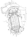
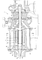
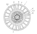
以下、本発明の一実施例を図1〜図3を用いて詳細に説明する。図1は、本発明に係るターボチャージャ1の一部を切り欠いて示した説明図である。図2は、本発明に係るターボチャージャ1の断面図である。図3は、本発明に係るターボチャージャ1の断面図であって、図2のA−A線に沿った位置に相当する断面図である。
Hereinafter, an embodiment of the present invention will be described in detail with reference to FIGS. FIG. 1 is an explanatory view in which a part of a
ターボチャージャ1は、例えば車両等に搭載された内燃機関(図示せず)へ供給する空気を、ターボチャージャハウジング2内で2段階圧縮するものである。すなわち、ターボチャージャ1は、細長い円柱形状の軸部材6に、タービンホイール3と第1コンプレッサホイール4と第2コンプレッサホイール5とを同軸状に取り付けることで、排気エネルギーを利用した過給を行うものである。
The
略筒状のターボチャージャハウジング2は、図1、図2に示すように、一端側のタービンハウジング7と、他端側のメインハウジングとしてのコンプレッサハウジング8と、タービンハウジング7とコンプレッサハウジング8との間に位置する中間ハウジング9と、によって大略構成されており、内部に軸部材6が収容されている。
As shown in FIGS. 1 and 2, the substantially
軸部材6は、金属材料からなり、その一端にタービンホイール3が固定され、他端に第1コンプレッサホイール4が固定され、中間部分に第2コンプレッサホイール5が固定されている。
The
タービンハウジング7、コンプレッサハウジング8、中間ハウジング9は、例えば金属材料の鋳造品からなっている。
The turbine housing 7, the compressor housing 8, and the
タービンハウジング7には、タービンホイール3が収容されている。タービンホイール3は、例えば金属材料の鋳造品であって、複数のタービンブレード10を有している。
The turbine housing 7 accommodates the turbine wheel 3. The turbine wheel 3 is, for example, a casting made of a metal material, and has a plurality of
中間ハウジング9は、主として軸部材を支持するものである。また、この中間ハウジングは、タービンハウジング7とコンプレッサハウジング8とを軸方向に連結している。
The
コンプレッサハウジング8には、第1コンプレッサホイール4と、第2コンプレッサホイール5と、第1コンプレッサホイール4と第2コンプレッサホイール5の間に配置された電動機11と、第1コンプレッサホイール4と電動機11の間に介装された第1筒状部材12と、第2コンプレッサホイール5と電動機11の間に介装された第2筒状部材13と、が収容されている。
The
ここで、コンプレッサハウジング8は、第1ハウジング14と、第2ハウジング15と、第3ハウジング16とから大略構成されており、内部に第1コンプレッサホイール4で加圧された空気を第2コンプレッサホイール5に送る連通路17が形成されている。連通路17は、第1コンプレッサホイール4と第2コンプレッサホイール5との間に位置し、軸部材6外周面とコンプレッサハウジング8内周面との間に形成された軸部材6の軸方向に沿って連続した空間である。
Here, the
第1ハウジング14は、第1コンプレッサホイール4を主として収容するものである。第2ハウジング15は、連通路17内に第1筒状部材12と電動機11を主として収容するものであり、第1ハウジング14と第3ハウジング16とを軸方向で連結している。第3ハウジング16は、第2コンプレッサホイール5と第2筒状部材13とを主として収容するものであり、第2ハウジング15と中間ハウジング9とを軸方向で連結している。
The
第1コンプレッサホイール4は、例えば金属材料の鋳造品であって、複数の第1コンプレッサブレード18を有している。第2コンプレッサホイール5は、例えば金属材料の鋳造品であって、複数の第2コンプレッサブレード19を有している。
The first compressor wheel 4 is, for example, a cast product of a metal material, and has a plurality of
電動機11は、図2、図3に示すように、筒状の電動機ハウジング20と、電動機ハウジング20の内周側に固定されたスタータコイルからなる複数の固定子21と、軸部材6に固定された永久磁石からなる複数の回転子22と、から大略構成されている。この電動機11は、軸部材6を回転軸とするものであり、タービンホイール3の回転不足により十分な過給が行えない場合には、固定子21に通電することにより回転駆動してタービンホイール3の回転不足を補うことが可能となっている。また、電動機11は、状況に応じて発電することが可能である。
As shown in FIGS. 2 and 3, the
電動機ハウジング20は、例えば金属材料からなり、外周に軸方向に沿った複数の放熱フィン23と放熱フィン23に比べて厚肉の複数のリブ24とを有している。この電動機ハウジング20は、リブ24が電動機ハウジング20半径方向から第2ハウジング15に図示せぬボルトで固定されている。また、電動機ハウジング20は、第1コンプレッサホイール側の端部に第1筒状部材12が図示せぬボルトにより固定されているともに、第2コンプレッサホイール側の端部に第2筒状部材13が軸方向から図示せぬボルトで固定されている。
The
第1筒状部材12は、例えば金属材料の鋳造品であって、外周に複数の整流フィン25を有している。整流フィン25は、第1コンプレッサホイール4で加圧された空気の流れを整流しつつ、電動機ハウジング20と第2ハウジング15との間の空間に導入するものである。この第1筒状部材12は、第1コンプレッサホイール4側の端部が、第1コンプレッサホイール4の背面と離間しているとともに、第2コンプレッサホイール5側の端部が電動機ハウジング20の第1コンプレッサホイール4側の端部に図示せぬボルトにより固定されている。
The first
第1筒状部材12には、軸方向に沿った複数の第1空気導入穴26が貫通形成されている。第1空気導入穴26は、一端が電動機ハウジング20の内周面よりも内側に開口し、他端が第1コンプレッサホイール4の背面と対向する位置に開口している。また、第1筒状部材12には、一端が第1筒状部材12の外周面に開口し、他端が第1空気導入穴26の中央部分に接続された径方向に沿った複数の第2空気導入穴27が形成されている。
A plurality of first air introduction holes 26 extending in the axial direction are formed through the first
第2筒状部材13は、例えば金属材料の鋳造品である。この第2筒状部材13には、軸方向に沿った複数の空気排出穴28が貫通形成されている。この空気排出穴28は、一端が第3ハウジング16内で連通路17と連通し、他端が電動機ハウジング20の内周面よりも内側に開口している。
The second
第1空気導入穴26と第2空気導入穴27によって、第1コンプレッサホイール4の背面側と整流フィン25の間から加圧された空気の一部が電動機ハウジング20に導入される。電動機ハウジング20内に導入された空気は、固定子21と固定子21の間や、固定子21と回転子22との間を軸方向に沿って第2コンプレッサホイール5側に流れ、第2筒状部材13に形成された複数の空気排出穴28を介して第3ハウジング16内の連通路17に排出される。なお、図2中の29は、軸部材6を回転可能に支持する軸受けである。
Part of the pressurized air is introduced into the
このような構成のターボチャージャ1においては、第2コンプレッサホイール5による空気の吸い込みにより、連通路17内の空気が常時第2コンプレッサホイール5側に向かって流れる。そのため、電動機11を第1コンプレッサホイール4と第2コンプレッサホイール5の間の連通路17内に配置することで、電動機11の周囲に空気が滞留せず電動機11を効率良く冷却することができ、ひいては電動機11の温度上昇による電動機11の駆動効率の悪化を効果的に抑制することができる。
In the
例えば、電動機11による過給圧の上昇アシスト時であれば、電動機11の温度上昇による電動機11の駆動効率の悪化が抑制されると、所期の過給圧が得られなくなることを回避できるため、十分な過給圧を確保して良好な車両運転状態を維持することができる。また、例えば、電動機11による発電時であれば、電動機11の温度上昇による電動機11の駆動効率の悪化が抑制されると、所期の発電効率が得られなくなることを回避できるため、排気による余剰のタービンホイール3の回転を効率良く電気エネルギーに回生することにより車両の燃費性能の向上に寄与できる。
For example, at the time of assisting the boosting of the supercharging pressure by the
そして、電動機ハウジング20の外周に放熱フィン23が設けられているので、電動機ハウジング20の内周に固定された固定子21の熱を効率良く連通路17の空気に放熱することができ、固定子21の温度上昇が抑制することができる。
And since the
また、第1コンプレッサホイール4で加圧された空気の一部が電動機11内に導入されているので、電動機11内に導入された空気で発熱した固定子21と固定子21の発熱によって温度上昇した回転子22を直接冷却することが可能となり、電動機11を内側と外側から効率良く冷却することができる。
In addition, since a part of the air pressurized by the first compressor wheel 4 is introduced into the
第1コンプレッサホイール4と第2コンプレッサホイール5によって空気を2段階で加圧しているので、軸部材6の回転数を相対的に低くしても所望の過給圧を得ることが可能となり、電動機11の発熱を抑制することができるとともに、電動機11の小型化が可能となる。
Since air is pressurized in two stages by the first compressor wheel 4 and the second compressor wheel 5, a desired supercharging pressure can be obtained even if the rotational speed of the
そして、第1コンプレッサホイール4と第2コンプレッサホイール5によって空気を2段階で加圧しているので、第1コンプレッサホイール4での過給率を大きくしなくても所望の過給圧を得ることができ、第1コンプレッサホイール4で圧縮された空気の温度上昇を低くして電動機11を効率良く冷却することができる。
Since the air is pressurized in two stages by the first compressor wheel 4 and the second compressor wheel 5, a desired supercharging pressure can be obtained without increasing the supercharging rate at the first compressor wheel 4. It is possible to cool the
また、ターボチャージャ1は、空気を2段階で加圧しているとともに、タービンホイール3の回転不足を電動機11で補うことが可能な構成となっているため、相対的に小型化した電動機11を用いても低回転から過給効率が良好なシステムをコンパクトに構築できる。さらに、ターボチャージャ1は、相対的に低回転での使用により回転力や遠心力を相対的に小さくでき、軸部材6を回転可能に支持する軸受け29や電動機11の強度等も比較的簡素で安価な構造にすることができる。
Moreover, since the
1…ターボチャージャ
2…ターボチャージャハウジング
3…タービンホイール
4…第1コンプレッサホイール
5…第2コンプレッサホイール
6…軸部材
8…コンプレッサハウジング
11…電動機
12…第1筒状部材
13…第2筒状部材
14…第1ハウジング
15…第2ハウジング
16…第3ハウジング
17…連通路
20…電動機ハウジング
23…放熱フィン
26…第1空気導入穴
27…第2空気導入穴
28…空気排出穴
DESCRIPTION OF
Claims (2)
軸部材を介して上記タービンホイールと同軸に連結された第1及び第2コンプレッサホイールと、
上記第1、第2コンプレッサホイールを収容するとともに、該第1コンプレッサホイールで加圧された空気を該第2コンプレッサホイールに送る連通路が内部に形成されたメインハウジングと、
上記連通路内に配置され、上記軸部材を回転軸とする電動機と、を有し、
上記電動機は、筒状の電動機ハウジングと、該電動機ハウジングの内周側に固定された固定子と、上記軸部材に固定された回転子と、を有し、
上記第1コンプレッサホイールで加圧された空気が上記電動機の外側を流れて上記第2コンプレッサホイールに送られているとともに、上記第1コンプレッサホイール側に位置する上記電動機ハウジングの一方の端部側から上記連通路内の空気が上記電動機ハウジング内に導入され、上記第2コンプレッサホイール側に位置する上記電動機ハウジングの他方の端部側から上記電動機ハウジング内の空気が上記連通路内に排出されていることを特徴とするターボチャージャ。 A turbine wheel driven by exhaust discharged from the internal combustion engine;
First and second compressor wheels connected coaxially to the turbine wheel via a shaft member;
A main housing that houses the first and second compressor wheels and has a communication passage formed therein for sending air pressurized by the first compressor wheel to the second compressor wheel;
An electric motor disposed in the communication path and having the shaft member as a rotation shaft,
The electric motor has a cylindrical electric motor housing, a stator fixed to the inner peripheral side of the electric motor housing, and a rotor fixed to the shaft member,
Above in conjunction with air pressurized by the first compressor wheel is transmitted to and outward flow the second compressor wheel of the motor, from one end side of the motor housing located on the first compressor wheel side Air in the communication passage is introduced into the motor housing, and air in the motor housing is discharged into the communication passage from the other end side of the motor housing located on the second compressor wheel side. Turbocharger characterized by that.
Priority Applications (5)
| Application Number | Priority Date | Filing Date | Title |
|---|---|---|---|
| JP2014257541A JP6460773B2 (en) | 2014-12-19 | 2014-12-19 | Turbocharger |
| PCT/JP2015/083986 WO2016098604A1 (en) | 2014-12-19 | 2015-12-03 | Turbocharger |
| CN201580068682.2A CN107110011B (en) | 2014-12-19 | 2015-12-03 | Turbocharger |
| EP15869810.0A EP3242002B1 (en) | 2014-12-19 | 2015-12-03 | Turbocharger |
| US15/534,220 US10364761B2 (en) | 2014-12-19 | 2015-12-03 | Turbocharger |
Applications Claiming Priority (1)
| Application Number | Priority Date | Filing Date | Title |
|---|---|---|---|
| JP2014257541A JP6460773B2 (en) | 2014-12-19 | 2014-12-19 | Turbocharger |
Publications (2)
| Publication Number | Publication Date |
|---|---|
| JP2016118136A JP2016118136A (en) | 2016-06-30 |
| JP6460773B2 true JP6460773B2 (en) | 2019-01-30 |
Family
ID=56126497
Family Applications (1)
| Application Number | Title | Priority Date | Filing Date |
|---|---|---|---|
| JP2014257541A Expired - Fee Related JP6460773B2 (en) | 2014-12-19 | 2014-12-19 | Turbocharger |
Country Status (5)
| Country | Link |
|---|---|
| US (1) | US10364761B2 (en) |
| EP (1) | EP3242002B1 (en) |
| JP (1) | JP6460773B2 (en) |
| CN (1) | CN107110011B (en) |
| WO (1) | WO2016098604A1 (en) |
Families Citing this family (19)
| Publication number | Priority date | Publication date | Assignee | Title |
|---|---|---|---|---|
| CN105121806A (en) * | 2013-02-22 | 2015-12-02 | 艾克莫特公司 | Electric rotor fit onto a turbomachine shaft |
| EP3141757A1 (en) * | 2015-09-08 | 2017-03-15 | Micronel AG | Turbo fan with cooling element |
| JP6668161B2 (en) | 2016-05-11 | 2020-03-18 | 株式会社マーレ フィルターシステムズ | Turbocharger |
| US20170335756A1 (en) * | 2016-05-22 | 2017-11-23 | Honeywell International Inc. | Turbocharger with two-stage series compressor driven by exhaust gas-driven turbine and electric motor |
| WO2018011967A1 (en) * | 2016-07-15 | 2018-01-18 | 三菱重工業株式会社 | Supercharging system and internal combustion engine |
| KR101896173B1 (en) * | 2017-02-01 | 2018-09-07 | 엘지전자 주식회사 | Fan Motor |
| US10215114B2 (en) * | 2017-03-01 | 2019-02-26 | GM Global Technology Operations LLC | Method and system for vehicle propulsion system control |
| DE102017205704A1 (en) * | 2017-04-04 | 2018-10-04 | Robert Bosch Gmbh | Turbocompressor, in particular for a fuel cell system |
| CN107542675A (en) * | 2017-09-20 | 2018-01-05 | 北京航空航天大学 | A kind of axle wanders about as a refugee heart tandem from cooling down refrigeration compressor |
| US11927193B2 (en) * | 2017-11-14 | 2024-03-12 | Garrett Transportation I Inc | Multi-stage compressor with turbine section for fuel cell system |
| JP6723977B2 (en) * | 2017-12-13 | 2020-07-15 | 三菱重工マリンマシナリ株式会社 | Supercharger |
| EP3739182A4 (en) | 2018-01-11 | 2021-08-25 | Gunma Prefecture | Exhaust casing for turbocharger, and method for manufacturing same |
| FR3078844B1 (en) * | 2018-03-08 | 2021-10-08 | Ifp Energies Now | DOUBLE-FLOW ELECTRIC MACHINE |
| EP3557081A1 (en) * | 2018-04-20 | 2019-10-23 | Belenos Clean Power Holding AG | Fuel cell comprising a fluid compressor |
| KR102627489B1 (en) * | 2021-08-16 | 2024-01-23 | 터보윈 주식회사 | Gas compressor with cooling system using pressure difference of gas |
| US20230151824A1 (en) * | 2021-11-12 | 2023-05-18 | Carrier Corporation | Multistage compressor with swirl-reducing ribs |
| US20230323886A1 (en) * | 2022-04-11 | 2023-10-12 | Carrier Corporation | Two stage mixed-flow compressor |
| EP4304059A1 (en) * | 2022-07-04 | 2024-01-10 | Volvo Truck Corporation | Energy transformation system |
| EP4358334A1 (en) * | 2022-10-18 | 2024-04-24 | Volvo Truck Corporation | A method of controlling an electric power source |
Family Cites Families (29)
| Publication number | Priority date | Publication date | Assignee | Title |
|---|---|---|---|---|
| US5605045A (en) * | 1995-09-18 | 1997-02-25 | Turbodyne Systems, Inc. | Turbocharging system with integral assisting electric motor and cooling system therefor |
| US5904471A (en) * | 1996-12-20 | 1999-05-18 | Turbodyne Systems, Inc. | Cooling means for a motor-driven centrifugal air compressor |
| US6102672A (en) * | 1997-09-10 | 2000-08-15 | Turbodyne Systems, Inc. | Motor-driven centrifugal air compressor with internal cooling airflow |
| JP2000130176A (en) | 1998-10-30 | 2000-05-09 | Isuzu Motors Ltd | Turbo charger with generator and motor |
| US6129524A (en) * | 1998-12-07 | 2000-10-10 | Turbodyne Systems, Inc. | Motor-driven centrifugal air compressor with axial airflow |
| US6305169B1 (en) * | 1999-02-22 | 2001-10-23 | Ralph P. Mallof | Motor assisted turbocharger |
| EP1069313B1 (en) * | 1999-07-16 | 2005-09-14 | Man Turbo Ag | Turbo compressor |
| US7025579B2 (en) | 2001-10-16 | 2006-04-11 | Innovative Turbo Systems Corporation | Bearing system for high-speed rotating machinery |
| US6739845B2 (en) * | 2002-05-30 | 2004-05-25 | William E. Woollenweber | Compact turbocharger |
| DE10156704A1 (en) * | 2001-11-13 | 2003-05-22 | Iav Gmbh | Method and appliance for operating exhaust gas turbocharger for IC engines with electrically assisted drive based on comparison of actual operating conditions and family of operating characteristics |
| US7055306B2 (en) * | 2003-04-30 | 2006-06-06 | Hamilton Sundstrand Corporation | Combined stage single shaft turbofan engine |
| JP2006333660A (en) * | 2005-05-27 | 2006-12-07 | Toyota Motor Corp | Motor and turbocharger using motor |
| JP2007023858A (en) * | 2005-07-14 | 2007-02-01 | Toyota Motor Corp | Bearing structure for turbocharger |
| JP4539487B2 (en) * | 2005-08-05 | 2010-09-08 | 株式会社Ihi | Supercharger with electric motor |
| JP4941782B2 (en) * | 2006-08-18 | 2012-05-30 | 株式会社Ihi | Electric turbocharger |
| US7677041B2 (en) * | 2006-10-11 | 2010-03-16 | Woollenweber William E | Bearing systems for high-speed rotating machinery |
| US20080107547A1 (en) * | 2006-10-19 | 2008-05-08 | General Electric | Systems for cooling motors for gas compression applications |
| EP2040353A1 (en) * | 2007-09-21 | 2009-03-25 | Siemens Aktiengesellschaft | Rotor can and method for its manufacture |
| FR2922970A1 (en) * | 2007-10-25 | 2009-05-01 | Airtechnologies | GAS COMPRESSION APPARATUS |
| DE102007062540A1 (en) * | 2007-12-20 | 2009-06-25 | Sycotec Gmbh & Co. Kg | Electric motor or generator |
| FI122036B (en) | 2008-01-10 | 2011-07-29 | Waertsilae Finland Oy | Piston engine turbocharger arrangement |
| US20100175377A1 (en) | 2009-01-12 | 2010-07-15 | Will Hippen | Cooling an electrically controlled turbocharger |
| US8181462B2 (en) * | 2009-06-23 | 2012-05-22 | Honeywell International Inc. | Turbocharger with two-stage compressor, including a twin-wheel parallel-flow first stage |
| EP2290241A1 (en) * | 2009-07-13 | 2011-03-02 | Siemens Aktiengesellschaft | Turbocompressor assembly with a cooling system |
| US8931304B2 (en) * | 2010-07-20 | 2015-01-13 | Hamilton Sundstrand Corporation | Centrifugal compressor cooling path arrangement |
| CN102312723A (en) * | 2011-09-23 | 2012-01-11 | 优华劳斯汽车系统(上海)有限公司 | Turbocharger |
| GB2497113B (en) * | 2011-12-01 | 2017-03-01 | Cummins Ltd | Turbocharger arrangement including a generator |
| US20130239568A1 (en) * | 2012-03-16 | 2013-09-19 | Calnetix Technologies, Llc | Turbo Assist |
| US10072667B2 (en) * | 2012-11-22 | 2018-09-11 | Mitsubishi Heavy Industries Engine & Turbocharger, Ltd. | Supercharger with electric motor and engine device provided with supercharger with electric motor |
-
2014
- 2014-12-19 JP JP2014257541A patent/JP6460773B2/en not_active Expired - Fee Related
-
2015
- 2015-12-03 US US15/534,220 patent/US10364761B2/en not_active Expired - Fee Related
- 2015-12-03 EP EP15869810.0A patent/EP3242002B1/en not_active Not-in-force
- 2015-12-03 WO PCT/JP2015/083986 patent/WO2016098604A1/en active Application Filing
- 2015-12-03 CN CN201580068682.2A patent/CN107110011B/en not_active Expired - Fee Related
Also Published As
| Publication number | Publication date |
|---|---|
| EP3242002B1 (en) | 2019-05-08 |
| CN107110011B (en) | 2019-08-02 |
| CN107110011A (en) | 2017-08-29 |
| JP2016118136A (en) | 2016-06-30 |
| US20170363024A1 (en) | 2017-12-21 |
| EP3242002A1 (en) | 2017-11-08 |
| WO2016098604A1 (en) | 2016-06-23 |
| US10364761B2 (en) | 2019-07-30 |
| EP3242002A4 (en) | 2018-07-11 |
Similar Documents
| Publication | Publication Date | Title |
|---|---|---|
| JP6460773B2 (en) | Turbocharger | |
| JP6668161B2 (en) | Turbocharger | |
| JP4605380B2 (en) | Electric turbocharger | |
| JP4671177B2 (en) | Electric turbocharger | |
| JP4697492B2 (en) | Electric turbocharger | |
| JP5622777B2 (en) | Compressor or vacuum machine | |
| KR101324226B1 (en) | Fluid charger | |
| JP2017516946A (en) | Turbocharger with electric machine | |
| KR20180037072A (en) | Supercharger and method for cooling electric motor | |
| CN204304647U (en) | Excitation Mode of Medium and Small Hydraulic Generator machine rotor support | |
| CN104065207A (en) | Water cooling motor for electric car | |
| KR102400801B1 (en) | Electric centrifugal compressor | |
| US20200248616A1 (en) | Electric media gap machine for a compressor and/or turbine, compressor and/or turbine | |
| JP2011185174A (en) | Turbo compressor and turbo refrigerator | |
| US10630144B2 (en) | Electric motor support mechanism, compressor, and turbocharger | |
| JP5189162B2 (en) | Exciter with sub-exciter | |
| US20200248704A1 (en) | Electric media gap machine, and compressor and/or turbine | |
| JP2014050133A (en) | Rotor, electric motor, and supercharger | |
| JP2015224601A (en) | Electric supercharger | |
| KR101289800B1 (en) | Permanent magnetic motor and fluid charger comprising the same | |
| JP2015224600A (en) | Electric supercharger | |
| US20210180511A1 (en) | Turbocharger | |
| US20200389068A1 (en) | Electrical machines |
Legal Events
| Date | Code | Title | Description |
|---|---|---|---|
| A621 | Written request for application examination |
Free format text: JAPANESE INTERMEDIATE CODE: A621 Effective date: 20170901 |
|
| A131 | Notification of reasons for refusal |
Free format text: JAPANESE INTERMEDIATE CODE: A131 Effective date: 20180724 |
|
| A521 | Request for written amendment filed |
Free format text: JAPANESE INTERMEDIATE CODE: A523 Effective date: 20180919 |
|
| A131 | Notification of reasons for refusal |
Free format text: JAPANESE INTERMEDIATE CODE: A131 Effective date: 20181106 |
|
| A521 | Request for written amendment filed |
Free format text: JAPANESE INTERMEDIATE CODE: A523 Effective date: 20181130 |
|
| TRDD | Decision of grant or rejection written | ||
| A01 | Written decision to grant a patent or to grant a registration (utility model) |
Free format text: JAPANESE INTERMEDIATE CODE: A01 Effective date: 20181211 |
|
| A61 | First payment of annual fees (during grant procedure) |
Free format text: JAPANESE INTERMEDIATE CODE: A61 Effective date: 20181225 |
|
| R150 | Certificate of patent or registration of utility model |
Ref document number: 6460773 Country of ref document: JP Free format text: JAPANESE INTERMEDIATE CODE: R150 |
|
| LAPS | Cancellation because of no payment of annual fees |