KR20180037072A - Supercharger and method for cooling electric motor - Google Patents
Supercharger and method for cooling electric motor Download PDFInfo
- Publication number
- KR20180037072A KR20180037072A KR1020187009313A KR20187009313A KR20180037072A KR 20180037072 A KR20180037072 A KR 20180037072A KR 1020187009313 A KR1020187009313 A KR 1020187009313A KR 20187009313 A KR20187009313 A KR 20187009313A KR 20180037072 A KR20180037072 A KR 20180037072A
- Authority
- KR
- South Korea
- Prior art keywords
- motor
- cooling
- air
- silencer
- intake air
- Prior art date
Links
Images

Classifications
-
- F—MECHANICAL ENGINEERING; LIGHTING; HEATING; WEAPONS; BLASTING
- F04—POSITIVE - DISPLACEMENT MACHINES FOR LIQUIDS; PUMPS FOR LIQUIDS OR ELASTIC FLUIDS
- F04D—NON-POSITIVE-DISPLACEMENT PUMPS
- F04D29/00—Details, component parts, or accessories
- F04D29/58—Cooling; Heating; Diminishing heat transfer
- F04D29/5806—Cooling the drive system
-
- F—MECHANICAL ENGINEERING; LIGHTING; HEATING; WEAPONS; BLASTING
- F02—COMBUSTION ENGINES; HOT-GAS OR COMBUSTION-PRODUCT ENGINE PLANTS
- F02B—INTERNAL-COMBUSTION PISTON ENGINES; COMBUSTION ENGINES IN GENERAL
- F02B33/00—Engines characterised by provision of pumps for charging or scavenging
- F02B33/32—Engines with pumps other than of reciprocating-piston type
- F02B33/34—Engines with pumps other than of reciprocating-piston type with rotary pumps
- F02B33/40—Engines with pumps other than of reciprocating-piston type with rotary pumps of non-positive-displacement type
-
- F—MECHANICAL ENGINEERING; LIGHTING; HEATING; WEAPONS; BLASTING
- F02—COMBUSTION ENGINES; HOT-GAS OR COMBUSTION-PRODUCT ENGINE PLANTS
- F02B—INTERNAL-COMBUSTION PISTON ENGINES; COMBUSTION ENGINES IN GENERAL
- F02B37/00—Engines characterised by provision of pumps driven at least for part of the time by exhaust
- F02B37/04—Engines with exhaust drive and other drive of pumps, e.g. with exhaust-driven pump and mechanically-driven second pump
- F02B37/10—Engines with exhaust drive and other drive of pumps, e.g. with exhaust-driven pump and mechanically-driven second pump at least one pump being alternatively or simultaneously driven by exhaust and other drive, e.g. by pressurised fluid from a reservoir or an engine-driven pump
-
- F—MECHANICAL ENGINEERING; LIGHTING; HEATING; WEAPONS; BLASTING
- F02—COMBUSTION ENGINES; HOT-GAS OR COMBUSTION-PRODUCT ENGINE PLANTS
- F02B—INTERNAL-COMBUSTION PISTON ENGINES; COMBUSTION ENGINES IN GENERAL
- F02B39/00—Component parts, details, or accessories relating to, driven charging or scavenging pumps, not provided for in groups F02B33/00 - F02B37/00
- F02B39/005—Cooling of pump drives
-
- F—MECHANICAL ENGINEERING; LIGHTING; HEATING; WEAPONS; BLASTING
- F04—POSITIVE - DISPLACEMENT MACHINES FOR LIQUIDS; PUMPS FOR LIQUIDS OR ELASTIC FLUIDS
- F04D—NON-POSITIVE-DISPLACEMENT PUMPS
- F04D17/00—Radial-flow pumps, e.g. centrifugal pumps; Helico-centrifugal pumps
- F04D17/08—Centrifugal pumps
- F04D17/10—Centrifugal pumps for compressing or evacuating
-
- F—MECHANICAL ENGINEERING; LIGHTING; HEATING; WEAPONS; BLASTING
- F04—POSITIVE - DISPLACEMENT MACHINES FOR LIQUIDS; PUMPS FOR LIQUIDS OR ELASTIC FLUIDS
- F04D—NON-POSITIVE-DISPLACEMENT PUMPS
- F04D25/00—Pumping installations or systems
- F04D25/02—Units comprising pumps and their driving means
- F04D25/024—Units comprising pumps and their driving means the driving means being assisted by a power recovery turbine
-
- F—MECHANICAL ENGINEERING; LIGHTING; HEATING; WEAPONS; BLASTING
- F04—POSITIVE - DISPLACEMENT MACHINES FOR LIQUIDS; PUMPS FOR LIQUIDS OR ELASTIC FLUIDS
- F04D—NON-POSITIVE-DISPLACEMENT PUMPS
- F04D25/00—Pumping installations or systems
- F04D25/02—Units comprising pumps and their driving means
- F04D25/06—Units comprising pumps and their driving means the pump being electrically driven
- F04D25/0606—Units comprising pumps and their driving means the pump being electrically driven the electric motor being specially adapted for integration in the pump
-
- F—MECHANICAL ENGINEERING; LIGHTING; HEATING; WEAPONS; BLASTING
- F04—POSITIVE - DISPLACEMENT MACHINES FOR LIQUIDS; PUMPS FOR LIQUIDS OR ELASTIC FLUIDS
- F04D—NON-POSITIVE-DISPLACEMENT PUMPS
- F04D29/00—Details, component parts, or accessories
- F04D29/06—Lubrication
- F04D29/063—Lubrication specially adapted for elastic fluid pumps
-
- F—MECHANICAL ENGINEERING; LIGHTING; HEATING; WEAPONS; BLASTING
- F04—POSITIVE - DISPLACEMENT MACHINES FOR LIQUIDS; PUMPS FOR LIQUIDS OR ELASTIC FLUIDS
- F04D—NON-POSITIVE-DISPLACEMENT PUMPS
- F04D29/00—Details, component parts, or accessories
- F04D29/40—Casings; Connections of working fluid
- F04D29/42—Casings; Connections of working fluid for radial or helico-centrifugal pumps
- F04D29/4206—Casings; Connections of working fluid for radial or helico-centrifugal pumps especially adapted for elastic fluid pumps
-
- F—MECHANICAL ENGINEERING; LIGHTING; HEATING; WEAPONS; BLASTING
- F04—POSITIVE - DISPLACEMENT MACHINES FOR LIQUIDS; PUMPS FOR LIQUIDS OR ELASTIC FLUIDS
- F04D—NON-POSITIVE-DISPLACEMENT PUMPS
- F04D29/00—Details, component parts, or accessories
- F04D29/66—Combating cavitation, whirls, noise, vibration or the like; Balancing
- F04D29/661—Combating cavitation, whirls, noise, vibration or the like; Balancing especially adapted for elastic fluid pumps
- F04D29/663—Sound attenuation
-
- Y—GENERAL TAGGING OF NEW TECHNOLOGICAL DEVELOPMENTS; GENERAL TAGGING OF CROSS-SECTIONAL TECHNOLOGIES SPANNING OVER SEVERAL SECTIONS OF THE IPC; TECHNICAL SUBJECTS COVERED BY FORMER USPC CROSS-REFERENCE ART COLLECTIONS [XRACs] AND DIGESTS
- Y02—TECHNOLOGIES OR APPLICATIONS FOR MITIGATION OR ADAPTATION AGAINST CLIMATE CHANGE
- Y02T—CLIMATE CHANGE MITIGATION TECHNOLOGIES RELATED TO TRANSPORTATION
- Y02T10/00—Road transport of goods or passengers
- Y02T10/10—Internal combustion engine [ICE] based vehicles
- Y02T10/12—Improving ICE efficiencies
-
- Y02T10/144—
Landscapes
- Engineering & Computer Science (AREA)
- Mechanical Engineering (AREA)
- General Engineering & Computer Science (AREA)
- Chemical & Material Sciences (AREA)
- Combustion & Propulsion (AREA)
- Physics & Mathematics (AREA)
- Thermal Sciences (AREA)
- Supercharger (AREA)
- Motor Or Generator Cooling System (AREA)
- Structures Of Non-Positive Displacement Pumps (AREA)
Abstract
이 과급기는, 컴프레서부에 접속된 로터축 (15) 의 사일런서 (26) 측 단부에 모터 (30) 가 장착된 전동 어시스트 과급기이며, 사일런서 (26) 의 직경 방향으로부터 사일런서 (26) 와 컴프레서부의 접속부를 향하여 흡입 공기 주류가 흘러들도록 사일런서 (26) 에 형성된 흡입 공기 도입로 (24) 와, 사일런서 (26) 에 있어서 적어도 출구가 로터축 (15) 의 축 중심선 상에 형성된 냉각 공기 취입 유로 (40) 를 구비하고 있다.This turbocharger is a motor assist supercharger in which a motor 30 is mounted on an end of a rotor shaft 15 connected to a compressor unit on the side of a silencer 26. The supercharger is a motor- A suction air introduction passage 24 formed in the silencer 26 so as to flow the main stream of the suction air toward the cooling air inlet passage 40 formed at the outlet of the silencer 26 on the axial center line of the rotor shaft 15, .

Description
본 발명은 과급기 및 모터 냉각 방법에 관한 것이다.The present invention relates to a supercharger and a motor cooling method.
종래, 내연 기관의 연소용 공기를 압축하고, 밀도가 높은 공기를 연소실 내로 보내는 과급기가 알려져 있으며, 예를 들어 선박용 디젤 기관이나 발전용 디젤 기관과 같은 2 스트로크 저속 기관 등에 있어서도 널리 사용되고 있다. 이와 같은 과급기는, 연소용 공기를 압축하는 압축기 및 압축기의 구동원이 되는 터빈이 로터축에 접속되고, 케이싱 내에 수납되어 일체로 회전한다. 또한, 터빈은, 내연 기관의 배기 가스가 보유하는 에너지에 의해 구동된다.BACKGROUND ART [0002] Conventionally, a supercharger for compressing air for combustion of an internal combustion engine and sending high-density air into the combustion chamber is known, and is widely used, for example, in a two-stroke low speed engine such as a marine diesel engine or a power generation diesel engine. In such a turbocharger, a compressor for compressing combustion air and a turbine serving as a drive source of the compressor are connected to the rotor shaft, housed in the casing, and rotated integrally. Further, the turbine is driven by the energy held by the exhaust gas of the internal combustion engine.
상기 서술한 과급기로서, 로터축에 고속의 전동 발전기를 접속한 하이브리드 과급기가 알려져 있다. 이 하이브리드 과급기는, 통상적인 과급기와 마찬가지로 가압한 연소용 공기를 내연 기관에 공급함과 함께, 잉여의 배기 가스 에너지를 사용하여 발전하여 전력을 공급할 수도 있다. 또한, 하이브리드 과급기의 전동 발전기를 압축기측의 사일런서 내부에 설치하는 경우, 일반적으로 사일런서를 관통하는 정도의 크기를 갖고 있다.As the above-described supercharger, there is known a hybrid supercharger in which a high-speed electric generator is connected to a rotor shaft. The hybrid supercharger may supply compressed air for combustion to an internal combustion engine as well as a conventional supercharger, and may generate electric power by using excess exhaust gas energy. Further, when the electric generator of the hybrid supercharger is installed inside the silencer of the compressor, it generally has a size enough to penetrate the silencer.
또, 상기 서술한 하이브리드 과급기의 전동 발전기로 바꾸어 소형화한 모터를 채용하고, 이 모터를 과급기에 내장한 전동 어시스트 과급기가 알려져 있다. 이 전동 어시스트 과급기는, 로터축을 흡입 공기 도입로측으로 연장한 축연장부에 소형화한 모터가 장착된다. 이 경우, 모터가 소형이기 때문에, 모터 로터의 중량을 기존의 과급기 베어링에 의해 충분히 지지하는 것이 가능하기 때문에, 모터 전용의 베어링을 불필요로 한다. 즉, 모터 전용의 베어링을 갖지 않는 모터 오버행 구조가 일반적이다. 이와 같은 전동 어시스트 과급기는, 예를 들어 주기관 저부하시에 충분한 배기 가스량이 얻어지지 않는 경우, 주기 (主機) 에 대한 소기 압력이 부족해지기 때문에, 종래의 보조 블로어의 사용으로 바꾸어 모터에 통전하고, 모터의 구동력을 가하여 압축기의 구동을 가세한다.There is also known a motor-assisted supercharger employing a motor that is miniaturized by replacing the electric motor-generator of the above-described hybrid supercharger with the motor incorporated in the supercharger. This electric motor assisted supercharger is equipped with a motor that is miniaturized at a shaft end portion where the rotor shaft extends toward the intake air introduction path side. In this case, since the motor is small, the weight of the motor rotor can be sufficiently supported by the conventional supercharger bearing, so that a motor dedicated bearing is not required. That is, a motor overhang structure having no motor dedicated bearing is generally used. In such a motor-assisted supercharger, for example, when a sufficient amount of exhaust gas can not be obtained when the main engine is running, the required pressure for the main engine is insufficient, so that the motor is switched to use the conventional auxiliary blower, The driving force of the motor is applied to the driving of the compressor.
또, 하기의 특허문헌 1 에는, 전동 과급기에서 사용되는 모터의 과열을 방지하기 위해서, 냉각 매체의 오일을 순환시켜 모터를 냉각시키는 제어 기술이 개시되어 있다.Patent Document 1 below discloses a control technique for cooling a motor by circulating oil of a cooling medium in order to prevent overheating of the motor used in the motor-driven supercharger.
그런데, 상기 서술한 전동 어시스트 과급기의 모터에는, 모터 전용의 베어링을 갖지 않는 모터 오버행 구조를 채용하고 있는 것이 있다. 이와 같은 모터 오버행 구조의 경우, 소형화된 모터의 모터 로터가 과급기의 로터축의 연장부에 장착되어 있다. 이 때문에, 모터 로터에 전용의 베어링을 형성할 필요가 없고, 과급기 본체를 지지하는 베어링 (로터축의 베어링) 에 의해 지지된 구조로 되어 있다.Incidentally, there is a motor overhang structure which does not have a bearing dedicated to a motor is adopted as the motor of the electric assist supercharger described above. In the case of such a motor overhang structure, the motor rotor of the miniaturized motor is mounted on the extended portion of the rotor shaft of the supercharger. Therefore, there is no need to form a dedicated bearing for the motor rotor, and the structure is supported by bearings (bearings of the rotor shaft) that support the supercharger main body.
또, 특허문헌 1 에 있어서는, 모터의 과열을 방지하기 위해서, 베어링에 공급하는 오일 (윤활유) 을 순환시켜 모터를 냉각시키고 있다. 그러나, 모터 오버행 구조의 전동 어시스트 과급기에 있어서는, 모터 전용의 베어링을 갖고 있지 않다. 이 때문에, 모터의 냉각 매체로서 윤활유를 사용할 수 없고, 따라서, 예를 들어, 과급기 흡입 공기를 사용하여 냉각시키는 방법이 채용되어 있다.Further, in Patent Document 1, in order to prevent overheating of the motor, oil (lubricating oil) supplied to the bearing is circulated to cool the motor. However, the electric assist turbocharger of the motor overhang structure does not have a motor dedicated bearing. For this reason, it is not possible to use lubricating oil as a cooling medium for the motor, and therefore, for example, a method of cooling by using supercharger intake air is employed.
또한, 상기 서술한 하이브리드 과급기 등과 같이, 모터 전용의 베어링을 갖는 모터를 채용한 구조로 하는 것도 가능하기는 하지만, 이와 같은 구조로 하는 경우에는, 윤활유 배관과 오일 제거를 위한 압축 공기 배관의 신설이 필요해진다. 또한, 과급기와 모터가 각각 베어링을 가짐으로써, 과급기와 모터 사이의 축방향 변위, 심 (芯) 어긋남을 흡수하기 위해서 다이어프램 커플링 등이 필요해진다. 이 때문에, 비용이 올라 레트로피트 (retrofit) 가 어려워진다.Although it is also possible to adopt a structure employing a motor having bearings dedicated to motors, such as the above-described hybrid supercharger, in the case of such a structure, the installation of a lubricating oil pipe and a compressed air pipe for oil removal It becomes necessary. Further, by having the supercharger and the motor each bearing, a diaphragm coupling or the like is required in order to absorb the axial displacement and the core deviation between the supercharger and the motor. As a result, the cost is increased and the retrofit becomes difficult.
이와 같은 배경으로부터, 예를 들어 모터 오버행 구조와 같이, 컴프레서부에 접속된 로터축의 사일런서측 단부 (端部) 에 모터가 장착된 구조를 채용하고 있는 과급기에 있어서는, 모터의 냉각 매체에 과급기 흡입 공기를 사용하여 효율적으로 냉각시키는 것이 요망된다.In such a background, for example, in a supercharger employing a structure in which a motor is mounted on a silencer side end portion of a rotor shaft connected to a compressor section, such as a motor overhang structure, It is desired to cool it efficiently.
본 발명은, 상기 과제를 해결하기 위해서 이루어진 것으로, 그 목적으로 하는 바는, 컴프레서부에 접속된 로터축의 사일런서측 단부에 모터가 장착된 구조를 채용하고 있는 과급기에 있어서, 냉각 매체에 과급기 흡입 공기를 사용하여 효율적으로 모터를 냉각시킬 수 있는 과급기 및 과급기의 모터 냉각 방법을 제공하는 것에 있다.SUMMARY OF THE INVENTION The present invention has been made in order to solve the above problems, and an object of the present invention is to provide a supercharger employing a structure in which a motor is mounted on a silencer side end portion of a rotor shaft connected to a compressor section, And to provide a motor cooling method for a supercharger and a supercharger which can efficiently cool the motor.
본 발명은 상기 과제를 해결하기 위해서, 하기의 수단을 채용하였다.In order to solve the above problems, the present invention employs the following means.
본 발명의 제 1 양태에 관련된 과급기는, 컴프레서부에 접속된 로터축의 사일런서측 단부에 모터가 장착된 과급기로서, 상기 사일런서의 직경 방향으로부터 상기 사일런서와 상기 컴프레서부의 접속부를 향하여 흡입 공기 주류가 흘러들도록 상기 사일런서에 형성된 흡입 공기 도입로와, 상기 사일런서에 있어서 적어도 출구가 로터축의 축 중심선 상에 형성된 냉각 공기 취입 유로를 구비한다.A supercharger according to a first aspect of the present invention is a supercharger in which a motor is mounted on a silencer side end portion of a rotor shaft connected to a compressor portion so that a suction air stream flows from a radial direction of the silencer toward a connection portion between the silencer and the compressor portion An intake air introduction path formed in the silencer, and a cooling air intake flow path formed in the silencer at least at an outlet on an axial center line of the rotor shaft.
본 발명의 제 1 양태에 관련된 과급기에 의하면, 상기 사일런서의 직경 방향으로부터 상기 사일런서와 상기 컴프레서부의 접속부를 향하여 흡입 공기 주류가 흘러들도록 상기 사일런서에 형성된 흡입 공기 도입로와, 상기 사일런서에 있어서 적어도 출구가 로터축의 축 중심선 상에 형성된 냉각 공기 취입 유로를 구비하고 있다. 이 때문에, 냉각 공기 취입 유로를 통과하는 냉각용 흡입 공기는, 전체량이 동축 상에 있는 모터를 향하여 공급되고, 과급기 흡입 공기의 일부가 모터 내부나 주변부에 공급된다. 이 때문에, 효율적으로 냉각을 실시하는 것이 가능해진다.According to a supercharger according to the first aspect of the present invention, there is provided a supercharger comprising: a suction air introduction passage formed in the silencer such that a suction air stream flows from a radial direction of the silencer toward a connection portion between the silencer and the compressor; And a cooling air intake flow path formed on a shaft center line of the rotor shaft. Therefore, the cooling intake air passing through the cooling air intake passage is supplied toward the motor on the coaxial basis, and a part of the supercharger intake air is supplied to the inside or the periphery of the motor. Therefore, it is possible to perform cooling efficiently.
상기 양태의 과급기에 있어서, 상기 흡입 공기 도입로는, 상기 흡입 공기 주류를 상기 모터의 축 중심 방향으로 유도하도록 경사벽을 구비하는 것이 바람직하다. 이에 따라, 모터를 향하여 공급되는 흡입 공기 주류의 공급량을 늘리고, 모터의 냉각 효율을 향상시키는 것이 가능해진다.In the supercharger of the above aspect, it is preferable that the intake air introduction passage has an inclined wall to guide the main stream of the intake air in the axial center direction of the motor. Thus, it is possible to increase the supply amount of the main stream of the intake air supplied toward the motor and improve the cooling efficiency of the motor.
상기 양태의 과급기에 있어서, 상기 모터의 상기 사일런서측 단부에, 상기 흡입 공기 주류를 상기 모터의 축 중심 방향으로 유도하도록 축경 (縮徑) 한 냉각 공기 도입로를 구비하는 것이 바람직하다. 이에 따라, 모터 내부를 향하여 과급기 흡입 공기를 확실하게 유도하는 것이 가능해진다.In the supercharger of the above aspect, it is preferable that a cooling air introduction path is provided at the silencer side end of the motor, the cooling air introduction path having a reduced diameter to guide the main stream of the intake air in the axial center direction of the motor. As a result, it is possible to reliably guide the supercharger intake air toward the inside of the motor.
상기 양태의 과급기에 있어서, 상기 모터가, 원통 형상의 하우징과, 그 하우징의 내부에 수납되어 있는 스테이터와, 상기 로터축의 단부에 접속되어 상기 스테이터의 내부에서 회전하는 영구 자석을 구비한 모터 로터를 구비하고, 상기 하우징의 내주면에 1 또는 복수의 오목 홈부를 형성함과 함께, 상기 내주면 및 상기 오목 홈부에 방열 그리스를 도포함으로써, 하우징으로부터의 방열성을 향상시킬 수 있다.In the supercharger of the above aspect, the motor includes a cylindrical housing, a stator accommodated in the housing, and a motor rotor connected to an end of the rotor shaft and having a permanent magnet rotating inside the stator, And one or a plurality of concave groove portions are formed on the inner circumferential surface of the housing, and heat dissipation grease is applied to the inner circumferential surface and the concave groove portion, so that heat radiation from the housing can be improved.
이 경우, 상기 하우징의 외벽면에 방열 핀을 형성함으로써, 하우징으로부터의 방열성을 보다 한층 향상시킬 수 있다.In this case, heat dissipation from the housing can be further improved by forming the heat dissipation fin on the outer wall surface of the housing.
본 발명의 제 2 양태에 관련된 과급기의 모터 냉각 방법은, 터빈부 및 컴프레서부를 구비한 로터축의 사일런서측 단부에 모터가 장착된 과급기의 모터 냉각 방법으로서, 상기 사일런서의 공기 취입구로부터 도입되어 흡입 공기 도입로를 통과하는 흡입 공기 주류와, 상기 사일런서에 있어서 적어도 유로의 출구부가 상기 로터축의 축 중심선 상에 형성된 냉각 공기 취입 유로를 통과하는 냉각용 흡입 공기에 의해 상기 모터를 냉각시키는 것이다.A motor cooling method for a supercharger according to a second aspect of the present invention is a motor cooling method for a turbocharger in which a motor is mounted on a silencer side end portion of a rotor shaft having a turbine portion and a compressor portion and is introduced from an air intake port of the silencer, Wherein the motor is cooled by the intake air mainstream passing through the introduction passage and the cooling intake air through which at least an outlet portion of the oil passage in the silencer passes through the cooling air intake passage formed on the shaft centerline of the rotor shaft.
이와 같은 본 발명의 제 2 양태에 관련된 과급기의 모터 냉각 방법에 의하면, 상기 사일런서의 공기 취입구로부터 도입되어 흡입 공기 도입로를 통과하는 흡입 공기 주류와, 상기 사일런서에 있어서 적어도 유로의 출구부가 상기 로터축의 축 중심선 상에 형성된 냉각 공기 취입 유로를 통과하는 냉각용 흡입 공기에 의해 상기 모터를 냉각시킨다. 이 때문에, 냉각 공기 취입 유로를 통과하는 냉각용 흡입 공기의 전체량이 동축 상에 있는 모터를 향하여 공급되고, 또, 과급기 흡입 공기의 일부가 모터 내부나 주변부에 대해 공급되어, 냉각을 효율적으로 실시하는 것이 가능해진다.According to the motor cooling method of the supercharger according to the second aspect of the present invention, the intake air mainstream introduced from the air intake port of the silencer and passing through the intake air introduction passage, and at least an outlet portion of the oil passage in the silencer, And the motor is cooled by the cooling intake air passing through the cooling air intake passage formed on the shaft center line of the shaft. Therefore, the total amount of cooling intake air passing through the cooling air intake flow path is supplied toward the coaxial motor, and a part of the supercharger intake air is supplied to the inside and the periphery of the motor, Lt; / RTI >
상기 서술한 본 발명에 의하면, 컴프레서부에 접속된 로터축의 사일런서측 단부에 모터가 장착된 구조의 과급기에 있어서, 모터의 냉각 매체로서 과급기 흡입 공기의 일부를 사용하고, 모터를 효율적으로 확실하게 냉각시키는 것이 가능해진다. 이 결과, 모터를 구비한 과급기는, 그 신뢰성이나 내구성이 향상된다는 현저한 효과가 얻어진다.According to the present invention described above, in a supercharger having a motor mounted on a silencer side end portion of a rotor shaft connected to a compressor unit, a part of the supercharger intake air is used as a cooling medium for the motor, . As a result, the supercharger equipped with the motor has a remarkable effect that the reliability and durability thereof are improved.
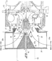
도 1 은, 본 발명에 관련된 과급기 및 모터 냉각 방법의 일 실시형태를 나타내는 주요부 단면도이다.
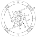
도 2 는, 소정 위치에 장착된 모터를 사일런서 방향에서 본 도 1 의 좌측면도이다.
도 3 의 (a) 는 모터를 구성하는 하우징의 좌측면도, (b) 는 모터를 구성하는 하우징의 종단면도이다.
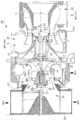
도 4 는, 본 발명에 관련된 과급기의 개략 구성예를 나타내는 종단면도이다.
도 5 는, 도 4 에 나타내는 과급기의 모터 주변부를 확대한 도면이다.BRIEF DESCRIPTION OF DRAWINGS FIG. 1 is a sectional view of a main part showing one embodiment of a supercharger and a motor cooling method according to the present invention. FIG.
Fig. 2 is a left side view of Fig. 1 viewed from a silencer direction of a motor mounted at a predetermined position; Fig.
Fig. 3 (a) is a left side view of the housing constituting the motor, and Fig. 3 (b) is a longitudinal sectional view of the housing constituting the motor.
4 is a longitudinal sectional view showing a schematic configuration example of a supercharger according to the present invention.
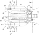
Fig. 5 is an enlarged view of the peripheral portion of the motor of the turbocharger shown in Fig. 4;
이하, 본 발명에 관련된 과급기 및 모터 냉각 방법에 대하여, 그 일 실시형태를 도면에 기초하여 설명한다.Hereinafter, a supercharger and a motor cooling method according to the present invention will be described with reference to the drawings.
도 4 는, 본 발명에 관련된 과급기의 일례로서, 전동 어시스트 과급기의 개략 구성예를 나타내는 종단면도이다. 도시하는 전동 어시스트 과급기 (이하, 「과급기」 라고 부른다) (10) 는, 예를 들어, 도시되지 않은 선박용 디젤 기관 (예를 들어, 저속 2 사이클 디젤 기관) 에 구비되어, 선박용 디젤 기관을 구성하는 실린더 라이너 (도시하지 않음) 의 내부와 연통하는 급기 매니폴드 (도시하지 않음) 에 압축된 공기를 공급하는 장치이다.4 is a longitudinal sectional view showing an example of a schematic configuration of an electric assist turbocharger as an example of a supercharger according to the present invention. (Hereinafter referred to as " supercharger ") 10 is provided in, for example, a marine diesel engine (for example, a low speed two-cycle diesel engine) And supplies compressed air to an air supply manifold (not shown) communicating with the inside of a cylinder liner (not shown).
도 4 에 나타내는 바와 같이, 본 실시형태의 과급기 (10) 는, 가스 입구 케이싱 (11), 가스 출구 케이싱 (12), 베어링대 (13) 및 컴프레서측의 공기 안내 케이싱 (14) 이 볼트 (도시하지 않음) 에 의해 일체로 체결됨으로써 구성되어 있다. 로터축 (15) 은, 베어링대 (13) 내에 형성한 트러스트 베어링 (16) 및 래디얼 베어링 (17, 18) 에 의해 자유롭게 회전할 수 있도록 지지되어 있고, 일단부에 터빈부를 구성하는 터빈 (19) 을 갖고, 타단부에 컴프레서부를 구성하는 컴프레서 날개차 (날개바퀴) (20) 를 갖고 있다.4, the
터빈 (19) 은, 외주부에 다수의 블레이드 (19a) 를 갖고 있다. 이 블레이드 (19a) 는, 가스 입구 케이싱 (11) 에 형성된 배기 가스 도입로 (22) 와, 가스 출구 케이싱 (12) 에 형성된 배기 가스 배출로 (23) 의 사이에 배치되어 있다.The turbine (19) has a plurality of blades (19a) on its outer peripheral portion. The
한편, 컴프레서 날개차 (20) 는, 외주부에 다수의 블레이드 (20a) 를 갖고 있다. 이 블레이드 (20a) 는, 과급기 케이싱의 일부인 공기 안내 케이싱 (14) 에 형성된 흡입 공기 도입로 (흡기 유로) (24) 의 하류측에 배치되어 있다. 흡입 공기 도입로 (24) 는, 컴프레서 날개차 (20) 를 통해서 와류실 (25) 에 접속되고, 또한, 와류실 (25) 은 도시되지 않은 흡입 공기 도입로를 통해서 엔진의 연소실에 접속되어 있다.On the other hand, the
또, 상기 서술한 과급기 (10) 는, 흡입 공기 도입로 (24) 의 상류측에 사일런서 (26) 를 구비하고 있다. 이 사일런서 (26) 는, 컴프레서부에서 압축하는 흡입 공기가 흡입 공기 도입로 (24) 에 흡입되는 전단 (상류측) 에, 즉 흡입 공기 도입로 (24) 의 입구부 상류측에 설치되어 있다. 이 사일런서 (26) 는, 흡입 공기를 통과시킴으로써 공기류를 정류하는 필터 기능과, 공기 흡입에 의해 발생하는 소음을 흡수하는 소음 기능을 갖고 있다. 이 사일런서 (26) 는, 중간 피스 (27) 를 통해서 공기 안내 케이싱 (14) 에 지지되고 있다.The above-described
그리고, 본 실시형태의 과급기 (10) 는, 로터축 (15) 에 접속한 모터 (30) 를 구비하고 있다. 이 모터 (30) 는, 하이브리드 과급기에 이용되고 있던 전동 발전기의 발전 기능을 생략하고, 전동 기능으로 좁힘으로써 소형화한 것이다. 이 때문에, 모터 (30) 는, 로터축 (15) 을 흡입 공기 도입로 (24) 측으로 연장하여 장착하는 구조, 즉, 모터 (30) 가 전용의 베어링을 갖지 않는 모터 오버행 구조가 된다. 따라서, 모터 (30) 및 후술하는 모터 (30) 의 모터 로터 (31) 는, 로터축 (15) 을 지지하는 트러스트 베어링 (16) 및 래디얼 베어링 (17, 18) 에 의해 지지된 구조가 된다.The
도 5 는, 상기 서술한 모터 (30) 의 주변부를 확대한 도면이다.5 is an enlarged view of a peripheral portion of the
모터 (30) 는, 모터 로터 (31), 스테이터 (32) 및 하우징 (33) 을 주된 구성 요소로 한다. 이 중, 모터 로터 (31) 는, 외주면에 영구 자석을 구비하는 원기둥 형상의 부재이며, 그 일단부가 로터축 (15) 의 단부와 플랜지 결합에 의해 접속되어 있다. 이 플랜지 결합은, 로터축 (15) 의 흡입 공기 도입로 (24) 측 (동 도면에 있어서 좌측) 이 되는 단부에 형성한 플랜지 (15a) 와, 모터 로터 (31) 의 컴프레서 날개차 (20) 측 (동 도면에 있어서 우측) 이 되는 단부에 형성한 플랜지 (31a) 를 접합하고, 복수의 볼트·너트 (34) 를 사용하여 연결한 것이다.The
스테이터 (32) 는, 원통 형상의 하우징 (33) 내에 수납 설치되어 있다. 이 하우징 (33) 은, 도 4 에 나타내는 바와 같이, 서포트 부재 (35) 를 통해서 공기 안내 케이싱 (14) 에 지지되고 있다. 또한, 서포트 부재 (35) 와 공기 안내 케이싱 (14) 의 사이 및 서포트 부재 (35) 와 하우징 (33) 의 사이는, 각각 육각 볼트 (36) 에 의해 연결되어 있다.The
스테이터 (32) 의 중공부에는, 축 중심부를 통과하는 모터 로터 (31) 가 스테이터 (32) 에 대해서 비접촉 상태로 배치 형성되어 있다. In the hollow portion of the stator (32), a motor rotor (31) passing through the axial center portion is formed in a noncontact state with respect to the stator (32).
또, 하우징 (33) 의 흡입 공기 도입로 (24) 측이 되는 선단부에는, 캡 (37) 이 육각 구멍이 부착된 볼트 (38) 에 의해 고정되어 장착되어 있다. 이 캡 (37) 은, 사일런서 (26) 측으로부터 컴프레서 날개차 (20) 측을 향해 위치하고, 축 중심부에는 원형의 개구부 (37a) 가 형성되어 있다. 즉, 모터 (30) 는, 로터축 (15) 의 축연장부가 사일런서 (26) 에 도달하지 않는 크기까지 소형화되어 있다.A
그런데, 상기 서술한 구성의 과급기 (10) 는, 운전시에 온도 상승하는 모터 (30) 를 냉각시키는 것이 필요해진다. 이 때문에, 본 실시형태에서는, 과급기 흡입 공기의 일부를 사용하여 모터 (30) 를 냉각시킨다.However, the
모터 (30) 의 냉각에 사용하는 과급기 흡입 공기는, 도 1 에 나타내는 바와 같이, 사일런서 (26) 의 공기 취입구 (26a) 로부터 도입되어 흡입 공기 도입로 (24) 를 통과하는 흡입 공기 주류와, 사일런서 (26) 의 축방향 중심부를 관통하여 로터축 (15) 의 축 중심선 상에 형성된 냉각 공기 취입 유로 (40) 를 통과하는 냉각용 흡입 공기를 구비하고 있다. 즉, 과급기 흡입 공기에는, 흡입 공기 도입로 (24) 를 통과하여 흡입된 흡입 공기 주류와, 냉각 공기 취입 유로 (40) 를 통과하여 흡입된 냉각용 흡입 공기가 있고, 상이한 경로를 통과한 공기 (흡입 공기 주류 및 냉각용 흡입 공기) 가 합류하여 공기 안내 케이싱 (14) 내에 유입한다. 또한, 여기서의 냉각용 흡입 공기는, 흡입 공기 주류와 구별하기 위한 명칭이며, 용도를 냉각에만 한정하는 것은 아니다.As shown in Fig. 1, the supercharger intake air used for cooling the
흡입 공기 주류는, 사일런서 (26) 의 외주부에 형성한 공기 취입구 (26a) 로부터 흡입 공기 도입로 (24) 에 유입하고, 로터축 (15) 의 축방향을 향하여 공기 안내 케이싱 (14) 내에 유입한다. 이 흡입 공기 주류는, 일부가 냉각용 흡입 공기와 함께 모터 (30) 의 냉각에 사용된다. 또한, 흡입 공기 주류 및 냉각용 흡입 공기는, 모터 (30) 의 냉각에 사용된 것도 포함하여 공기 안내 케이싱 (14) 내에서 합류한 후, 컴프레서 날개차 (20) 에 의해 압축된다.The main intake air flows into the intake
한편, 냉각용 흡입 공기는, 냉각 공기 취입 유로 (40) 를 통과하여 유입하지만, 이 냉각 공기 취입 유로 (40) 는, 적어도 냉각 공기 취입 유로 (40) 의 출구 부분이 로터축 (15) 의 축 중심선 상에 있도록, 사일런서 (26) 를 관통하도록 형성되어 있다. 이 냉각 공기 취입 유로 (40) 는, 그 전체가 로터축 (15) 의 축 중심선 상에 존재하도록 사일런서 (26) 를 직선상으로 관통하고 있어도 된다. 이 때문에, 냉각 공기 취입 유로 (40) 의 출구 (41) 는, 로터축 (15) 의 축 중심선 상에 장착된 모터 (30) 의 캡 (37) 과 대향하여 개구한다. 즉, 냉각 공기 취입 유로 (40) 의 출구 (41) 는, 로터축 (15) 의 축 중심선 상에 있어서, 캡 (37) 의 개구부 (37a) 와 대향하고 있다.On the other hand, the cooling intake air flows through the cooling
또한, 냉각 공기 취입 유로 (40) 의 입구 (42) 는, 사일런서 (26) 의 축방향 단면 (端面) 에 장착한 단자대 (50) 의 내부에 개구하고, 단자대 (50) 의 외벽면 적소에 형성한 공기 취입구 (도시하지 않음) 로부터 냉각용 흡입 공기를 도입한다. 냉각 공기 취입 유로 (40) 의 입구 (42) 는, 냉각 공기 취입 유로 (40) 의 설치 방법에 의해, 로터축 (15) 의 축 중심선과 합치하지 않고, 축 중심에서 벗어난 위치에 입구 (42) 를 개구시켜도 된다.The
이 때문에, 냉각 공기 취입 유로 (40) 로부터 유입하는 냉각용 흡입 공기는, 그 전체량이 동축 상에 있는 모터 (30) 를 향하여 공급된다. 구체적으로 설명하면, 냉각 공기 취입 유로 (40) 의 출구 (41) 와, 모터 (30) 의 선단부에 장착된 캡 (37) 의 개구부 (37a) 가 동축 상에 있다. 이 때문에, 직선상의 냉각 공기 취입 유로 (40) 로부터 유출하는 냉각용 흡입 공기는, 그대로 직진하여 전체량이 개구부 (37a) 로부터 모터 (30) 내에 유입한다. 또, 흡입 공기 주류의 일부도 냉각용 흡입 공기와 합류하고, 개구부 (37a) 로부터 유입한다.Therefore, the cooling intake air flowing in from the cooling
이렇게 하여 모터 (30) 의 내부에 유입한 냉각용 흡입 공기 및 흡입 공기 주류의 일부는, 모터 로터 (31) 와 스테이터 (32) 의 사이에 형성되어 있는 간극을 통과하는 등 하여, 모터 (30) 의 캡 (37) 과 반대측으로부터 컴프레서 날개차 (20) 측으로 유출된다.A part of the cooling intake air and the intake air main stream which have flowed into the inside of the
이 결과, 모터 (30) 의 내부를 통과하여 흐르는 냉각용 흡입 공기 및 흡입 공기 주류의 일부는, 모터 (30) 로부터 흡열하여 냉각에 이용할 수 있다. 또, 흡입 공기 주류의 대부분이 모터 (30) 의 외주측을 통과하여 흐르므로, 이 흡입 공기 주류도 모터 (30) 로부터 흡열하여 냉각에 이용할 수 있다. 따라서, 과급기 흡입 공기의 일부를 사용하는 모터 (30) 의 냉각은, 모터 (30) 의 내부나 주변부를 통과하는 충분한 공랭용 공기량을 확실하게 확보할 수 있고, 특히, 모터 (30) 의 내부를 통과하는 공랭용 공기로서, 주로 냉각용 흡입 공기를 확실하게 도입하여 효율적으로 냉각시킬 수 있다.As a result, a part of the intake air for cooling and the mainstream of the intake air flowing through the inside of the
또, 상기 서술한 실시형태 (도 1 참조) 의 과급기 (10) 에는, 흡입 공기 도입로 (24) 의 로터축측 출구를 연장하고, 흡입 공기 주류를 모터 (30) 의 축 중심 방향으로 유도하도록 경사벽 (60) 을 형성하고 있다. 즉, 이 경사벽 (60) 은, 흡입 공기 도입로 (24) 를 형성하는 벽면 중, 로터축 (15) 측이 되는 유로 내측 벽면 (24a) 의 경사면을 냉각 공기 취입 유로 (40) 의 출구 (41) 까지 연장한 것이다. 또한, 경사벽 (60) 이 냉각 공기 취입 유로 (40) 의 출구 (41) 로부터 로터축측 (도 1 에 있어서 우측) 으로 돌출하면, 냉각용 흡입 공기의 흐름을 방해하게 되어, 냉각용 흡입 공기가 적절히 모터 (30) 내부로 유도되지 않게 되기 때문에 바람직하지 않다.The
또한, 이 경사벽 (60) 은, 그 연장선이, 캡 (37) 의 개구부 (37a) 내 또는 그 근방에서, 로터축 (15) 의 축 중심선 상에서 교차하는 각도로 설정 하면 된다.The inclined wall 60 may be set such that an extension line of the inclined wall 60 intersects the axial center line of the
이와 같은 경사벽 (60) 을 형성함으로써, 모터 (30) 를 향하여 공급되는 흡입 공기 주류의 공급량이 증가하므로, 모터 (30) 의 내부나 외주의 냉각에 이용하는 공랭용 공기량을 늘리고, 모터 (30) 의 냉각 효율을 향상시킬 수 있다.By forming the inclined walls 60, the supply amount of the intake air mainstream supplied to the
또, 상기 서술한 실시형태의 과급기 (10) 에는, 모터 (30) 의 사일런서 (26) 측이 되는 선단부에, 과급기 흡입 공기의 일부 및 냉각용 흡입 공기를 모터 (30) 의 축 중심 방향으로 유도하도록 컴프레서 날개차 (20) 측으로 축경한 콘 형상의 냉각 공기 도입로 (39) 를 형성하는 것이 바람직하다. 도시하는 구성예에서는, 도 1 및 도 5 에 나타내는 바와 같이, 캡 (37) 의 개구부 (37a) 를 형성하는 내주면 (37b) 및 스테이터 (32) 의 내주면 단부 (32a) 가 서로 연속하고, 콘 형상의 냉각 공기 도입로 (39) 를 형성하고 있지만, 캡 (37) 의 개구부 (37a) 측에만 부분적으로 냉각 공기 도입로 (39) 를 형성해도 된다.In the
이와 같은 냉각 공기 도입로 (39) 를 형성함으로써, 과급기 흡입 공기의 일부 및 냉각용 흡입 공기를 모터 (30) 의 내부를 향하여 확실하게 유도할 수 있다. 이 때문에, 모터 (30) 의 내부에서는, 모터 로터 (31) 와 스테이터 (32) 의 사이에 형성된 간극을 충분한 양의 공기가 흐르고, 효율이 좋은 냉각을 실시할 수 있다.By forming the cooling
또한, 스테이터 (32) 의 내주면 단부 (32a) 가 냉각 공기 도입로 (39) 의 일부를 형성함으로써, 모터 로터 (31) 와 스테이터 (32) 의 사이에 형성된 간극에 대해서 공기를 보다 확실하게 유도할 수 있다.The inner circumferential
또한, 상기 서술한 실시형태의 과급기 (10) 는, 예를 들어 도 3 의 (b) 에 나타내는 바와 같이, 하우징 (33) 의 내주면 (33a) 에 전체 둘레에 걸치는 1 또는 복수의 오목 홈부 (33b) 를 형성하고, 내주면 (33a) 및 오목 홈부 (33b) 에 방열 그리스를 도포하는 것이 바람직하다.3 (b), the
구체적으로 설명하면, 하우징 (33) 의 내주면 (33a) 에는, 전체 둘레에 걸치는 오목 홈부 (33b) 가 축방향으로 복수 (본 실시형태에서는 7 열) 형성되어 있다. 그리고, 내주면 (33a) 및 오목 홈부 (33b) 에 방열 그리스를 얇게 도포해 둠으로써, 운전시에 있어서의 하우징 (33) 으로부터의 방열성이 향상된다. 또, 하우징 (33) 으로부터의 방열성을 향상시키기 위해서, 하우징 (33) 의 외주면에는 복수의 방열 핀 (33c) 이 형성되어 있다.Specifically, on the inner
상기 서술한 바와 같이, 본 실시형태의 과급기 (10) 는, 과급기 흡입 공기로서, 사일런서 (26) 의 공기 취입구 (26a) 로부터 도입되어 흡입 공기 도입로 (24) 를 통과하는 흡입 공기 주류와, 흡입 공기 도입로 (24) 의 적어도 출구는 사일런서 (26) 의 축방향 중심부를 관통하여 로터축 (15) 의 축 중심선 상에 형성된 냉각 공기 취입 유로 (40) 를 통과하는 냉각용 흡입 공기를 사용하고, 그 일부를 공랭용 공기로 하여 모터 (30) 를 냉각시키는 모터 냉각 방법을 실시하고 있다.As described above, the
이 때문에, 특히, 냉각 공기 취입 유로 (40) 를 통과하는 냉각용 흡입 공기의 전체량이 동축 상에 있는 모터 (30) 를 향하여 공급되게 된다. 이 때문에 과급기 흡입 공기의 일부가 모터 (30) 의 내부나 주변부에 공급되기 때문에, 효율적으로 냉각을 실시하는 것이 가능해진다.Therefore, in particular, the total amount of cooling intake air passing through the cooling
상기 서술한 본 실시형태에 의해, 모터 오버행 구조를 채용하고 있는 과급기 (10) 는, 모터 (30) 의 냉각 매체로서, 냉각 공기 취입 유로 (40) 를 통과하는 냉각용 흡입 공기와 과급기 흡입 공기의 일부를 사용함으로써, 모터 (30) 를 효율적으로 확실하게 냉각시킬 수 있기 때문에, 과급기 (10) 의 신뢰성이나 내구성이 향상된다. The
또한, 본 발명은 상기 서술한 실시형태에 한정되는 것은 아니고, 그 요지를 일탈하지 않는 범위 내에 있어서 적절히 변경할 수 있다.Further, the present invention is not limited to the above-described embodiment, and can be appropriately changed within the range not deviating from the gist of the present invention.
10 : 전동 어시스트 과급기 (과급기)
11 : 가스 입구 케이싱
12 : 가스 출구 케이싱
13 : 베어링대
14 : 공기 안내 케이싱
15 : 로터축
19 : 터빈
20 : 컴프레서 날개차
22 : 배기 가스 도입로
23 : 배기 가스 배출로
24 : 흡입 공기 도입로
25 : 와류실
26 : 사일런서
30 : 모터
31 : 모터 로터
32 : 스테이터
33 : 하우징
33a : 내주면
33b : 오목 홈부
33c : 방열 핀
35 : 서포트 부재
36 : 육각 볼트
37 : 캡
39 : 냉각 공기 도입로
40 : 냉각 공기 취입 유로
60 : 경사벽10: Electric assist turbocharger (supercharger)
11: gas inlet casing
12: gas outlet casing
13: Bearing stand
14: air guide casing
15: Rotor shaft
19: Turbine
20: Compressor wing car
22: Exhaust gas introduction furnace
23: Exhaust gas discharge path
24: Intake air introduction path
25: swirl chamber
26: The Silencer
30: Motor
31: Motor rotor
32:
33: Housing
33a: inner peripheral surface
33b: concave groove
33c:
35: Support member
36: Hex bolts
37: Cap
39: cooling air introduction path
40: Cooling air intake flow path
60: inclined wall
Claims (6)
사일런서의 직경 방향으로부터 상기 사일런서와 상기 컴프레서부의 접속부를 향하여 흡입 공기 주류가 흘러들도록 상기 사일런서에 형성된 흡입 공기 도입로와,
상기 사일런서에 있어서 적어도 출구가 상기 로터축의 축 중심선 상에 형성된 냉각 공기 취입 유로를 구비하는 과급기.A supercharger equipped with a motor having an opening for introducing cooling air into an end portion of a rotor shaft connected to a compressor portion,
A suction air introduction path formed in the silencer so that a suction air mainstream flows from a radial direction of the silencer toward a connection portion between the silencer and the compressor,
Wherein at least an outlet of the silencer is provided on a shaft centerline of the rotor shaft.
상기 흡입 공기 도입로는, 상기 흡입 공기 주류를 상기 모터의 축 중심 방향으로 유도하도록 경사벽을 구비하는 과급기.The method according to claim 1,
Wherein the intake air introduction passage has an inclined wall to guide the main stream of the intake air in the axial center direction of the motor.
상기 모터의 상기 개구부에, 상기 흡입 공기 주류를 상기 모터의 축 중심 방향으로 유도하도록 축경 (縮徑) 한 냉각 공기 도입로를 구비하는 과급기.3. The method according to claim 1 or 2,
And a cooling air introduction path formed in the opening of the motor and having a reduced diameter to guide the main stream of the intake air in the direction of the axis of the motor.
상기 모터가, 원통 형상의 하우징과, 그 하우징의 내부에 수납되어 있는 스테이터와, 상기 로터축의 단부에 접속되어 상기 스테이터의 내부에서 회전하는, 영구 자석을 구비한 모터 로터를 구비하고,
상기 하우징의 내주면에 1 또는 복수의 오목 홈부를 형성함과 함께, 상기 내주면 및 상기 오목 홈부에 방열 그리스가 도포되어 있는 과급기.The method according to claim 1,
Wherein the motor includes a cylindrical housing, a stator accommodated in the housing, and a motor rotor connected to an end of the rotor shaft and rotating in the stator, the motor rotor comprising:
Wherein one or a plurality of concave groove portions are formed on the inner circumferential surface of the housing, and the inner circumferential surface and the concave groove portion are coated with heat dissipating grease.
상기 하우징의 외벽면에 방열 핀이 형성되어 있는 과급기.5. The method of claim 4,
And a heat dissipation fin is formed on an outer wall surface of the housing.
상기 사일런서의 공기 취입구로부터 도입되어 흡입 공기 도입로를 통과하는 흡입 공기 주류와, 상기 사일런서에 있어서 적어도 유로의 출구부가 상기 로터축의 축 중심선 상에 형성된 냉각 공기 취입 유로를 통과하는 냉각용 흡입 공기에 의해 상기 모터를 냉각시키는 과급기의 모터 냉각 방법.A motor cooling method for a turbocharger in which a motor is mounted on a silencer side end portion of a rotor shaft having a turbine portion and a compressor portion,
An intake air mainstream introduced from the air intake port of the silencer and passing through the intake air introduction passage and a cooling air intake passage for cooling the cooling air, And cooling the motor.
Applications Claiming Priority (3)
| Application Number | Priority Date | Filing Date | Title |
|---|---|---|---|
| JP2014032907A JP6223859B2 (en) | 2014-02-24 | 2014-02-24 | Supercharger and motor cooling method |
| JPJP-P-2014-032907 | 2014-02-24 | ||
| PCT/JP2015/054750 WO2015125910A1 (en) | 2014-02-24 | 2015-02-20 | Supercharger and method for cooling electric motor |
Related Parent Applications (1)
| Application Number | Title | Priority Date | Filing Date |
|---|---|---|---|
| KR1020167017140A Division KR102068390B1 (en) | 2014-02-24 | 2015-02-20 | Supercharger and method for cooling electric motor |
Publications (1)
| Publication Number | Publication Date |
|---|---|
| KR20180037072A true KR20180037072A (en) | 2018-04-10 |
Family
ID=53878408
Family Applications (2)
| Application Number | Title | Priority Date | Filing Date |
|---|---|---|---|
| KR1020187009313A KR20180037072A (en) | 2014-02-24 | 2015-02-20 | Supercharger and method for cooling electric motor |
| KR1020167017140A KR102068390B1 (en) | 2014-02-24 | 2015-02-20 | Supercharger and method for cooling electric motor |
Family Applications After (1)
| Application Number | Title | Priority Date | Filing Date |
|---|---|---|---|
| KR1020167017140A KR102068390B1 (en) | 2014-02-24 | 2015-02-20 | Supercharger and method for cooling electric motor |
Country Status (5)
| Country | Link |
|---|---|
| US (1) | US11396889B2 (en) |
| JP (1) | JP6223859B2 (en) |
| KR (2) | KR20180037072A (en) |
| CN (1) | CN105940201B (en) |
| WO (1) | WO2015125910A1 (en) |
Families Citing this family (14)
| Publication number | Priority date | Publication date | Assignee | Title |
|---|---|---|---|---|
| JP6563321B2 (en) | 2015-12-03 | 2019-08-21 | 三菱重工業株式会社 | Electric motor support mechanism, compressor, and supercharger |
| US10077785B2 (en) | 2016-04-21 | 2018-09-18 | Mitsubishi Heavy Industries, Ltd. | Impeller assembly, turbocharger, and method of assembling impeller assembly |
| USD849685S1 (en) | 2016-05-13 | 2019-05-28 | Mitsubishi Heavy Industries, Ltd. | Rotor for electric motor |
| USD868112S1 (en) | 2016-05-13 | 2019-11-26 | Mitsubishi Heavy Industries, Ltd. | Flange for compressor impeller |
| DE102016213182A1 (en) * | 2016-07-19 | 2018-01-25 | Man Diesel & Turbo Se | intake silencer |
| US10316692B2 (en) | 2016-12-20 | 2019-06-11 | Mitsubishi Heavy Industries, Ltd. | Vibration suppression method and vibration suppression apparatus for turbocharger capable of being driven by motor |
| US10704556B2 (en) * | 2017-08-30 | 2020-07-07 | Mitsubishi Heavy Industries, Ltd. | Motor, turbocharger and assembly method turbocharger |
| JP6723977B2 (en) | 2017-12-13 | 2020-07-15 | 三菱重工マリンマシナリ株式会社 | Supercharger |
| US20190203730A1 (en) * | 2017-12-29 | 2019-07-04 | Johnson Controls Technology Company | Thrust bearing placement for compressor |
| CN110730860B (en) * | 2018-05-17 | 2021-06-11 | 三菱重工业株式会社 | Vibration suppression method and vibration suppression device for supercharger capable of being driven by motor |
| JP7211400B2 (en) | 2020-06-26 | 2023-01-24 | トヨタ自動車株式会社 | fuel cell system |
| EP4053388A1 (en) * | 2021-03-04 | 2022-09-07 | Turbo Systems Switzerland Ltd. | Turbocharging assembly and method of controlling operation of a turbocharging assembly |
| CN114458625A (en) * | 2022-03-03 | 2022-05-10 | 深圳乐居智能电子有限公司 | Air inlet cover, fan assembly, air duct structure and floor sweeping robot |
| CN118517329A (en) * | 2024-07-19 | 2024-08-20 | 潍坊富源增压器有限公司 | Low-speed air supplementing structure of marine turbocharger |
Family Cites Families (24)
| Publication number | Priority date | Publication date | Assignee | Title |
|---|---|---|---|---|
| US3077731A (en) * | 1958-11-24 | 1963-02-19 | Gen Motors Corp | Compressor mechanism for internal combustion engines and the like |
| JPS5216458B2 (en) | 1972-10-13 | 1977-05-10 | ||
| JPS5649299U (en) * | 1979-09-25 | 1981-05-01 | ||
| JPS57191895U (en) * | 1981-05-29 | 1982-12-04 | ||
| JPS6296772A (en) | 1985-10-24 | 1987-05-06 | Yamaha Motor Co Ltd | Air cleaner |
| JPH03115737A (en) | 1989-09-29 | 1991-05-16 | Mitsubishi Heavy Ind Ltd | Supercharger system with variable matching mechanism |
| JPH0642359A (en) * | 1992-07-23 | 1994-02-15 | Fuji Heavy Ind Ltd | Supercharging pressure control method for engine |
| US6305169B1 (en) * | 1999-02-22 | 2001-10-23 | Ralph P. Mallof | Motor assisted turbocharger |
| GB0010895D0 (en) * | 2000-05-05 | 2000-06-28 | Nelson Burgess Ltd | Air intake silencer |
| US6739845B2 (en) | 2002-05-30 | 2004-05-25 | William E. Woollenweber | Compact turbocharger |
| JP4651305B2 (en) * | 2004-04-30 | 2011-03-16 | フルタ電機株式会社 | Low noise equipment for blowers |
| KR100923186B1 (en) * | 2005-08-05 | 2009-10-22 | 가부시키가이샤 아이에이치아이 | Supercharger with electric motor |
| JP4539487B2 (en) * | 2005-08-05 | 2010-09-08 | 株式会社Ihi | Supercharger with electric motor |
| JP2009013966A (en) * | 2007-07-09 | 2009-01-22 | Ihi Corp | Supercharger with electric motor |
| JP4780052B2 (en) * | 2007-07-19 | 2011-09-28 | 株式会社Ihi | Supercharger with electric motor |
| FI122036B (en) | 2008-01-10 | 2011-07-29 | Waertsilae Finland Oy | Piston engine turbocharger arrangement |
| JP4959753B2 (en) | 2009-06-02 | 2012-06-27 | 三菱電機株式会社 | Electric supercharger control device |
| KR20110139372A (en) | 2010-06-23 | 2011-12-29 | 동양물산기업 주식회사 | Axle case with passing groove of oil for lubrication of oil seal |
| WO2012061439A2 (en) * | 2010-11-01 | 2012-05-10 | Mission Motors | Electric motor and method of cooling |
| JP5825791B2 (en) * | 2011-01-19 | 2015-12-02 | 三菱重工業株式会社 | Supercharger and diesel engine equipped with the same |
| JP5843505B2 (en) * | 2011-07-12 | 2016-01-13 | 三菱重工業株式会社 | Silencer for supercharger, supercharger and hybrid supercharger equipped with the silencer |
| JP5433643B2 (en) | 2011-07-15 | 2014-03-05 | 三菱重工業株式会社 | Electric supercharging device and multistage supercharging system |
| JP5726095B2 (en) * | 2012-01-12 | 2015-05-27 | 三菱重工業株式会社 | Hybrid exhaust turbine turbocharger |
| US20130239568A1 (en) * | 2012-03-16 | 2013-09-19 | Calnetix Technologies, Llc | Turbo Assist |
-
2014
- 2014-02-24 JP JP2014032907A patent/JP6223859B2/en active Active
-
2015
- 2015-02-20 WO PCT/JP2015/054750 patent/WO2015125910A1/en active Application Filing
- 2015-02-20 KR KR1020187009313A patent/KR20180037072A/en active Application Filing
- 2015-02-20 KR KR1020167017140A patent/KR102068390B1/en active IP Right Grant
- 2015-02-20 US US15/115,633 patent/US11396889B2/en active Active
- 2015-02-20 CN CN201580003453.2A patent/CN105940201B/en active Active
Also Published As
| Publication number | Publication date |
|---|---|
| CN105940201B (en) | 2019-04-09 |
| WO2015125910A1 (en) | 2015-08-27 |
| CN105940201A (en) | 2016-09-14 |
| KR102068390B1 (en) | 2020-01-20 |
| JP6223859B2 (en) | 2017-11-01 |
| US20170167511A1 (en) | 2017-06-15 |
| KR20160090385A (en) | 2016-07-29 |
| US11396889B2 (en) | 2022-07-26 |
| JP2015158161A (en) | 2015-09-03 |
Similar Documents
| Publication | Publication Date | Title |
|---|---|---|
| KR20180037072A (en) | Supercharger and method for cooling electric motor | |
| US10364761B2 (en) | Turbocharger | |
| KR101644287B1 (en) | Supercharger manufacturing method and supercharger | |
| US8157544B2 (en) | Motor driven supercharger with motor/generator cooling efficacy | |
| US7352077B2 (en) | Motor-driven supercharger | |
| CN108368852B (en) | Electric centrifugal compressor for a turbine engine or aircraft | |
| US20120086217A1 (en) | Power Generation Apparatus | |
| KR20140066105A (en) | Charging device of a drive assembly | |
| CN108533387B (en) | Turbocharging device with motor/generator | |
| JP7373076B2 (en) | Multi-stage electric centrifugal compressor | |
| JP2010127239A (en) | Marine diesel engine | |
| KR101998533B1 (en) | Motor support mechanism, compressor, and supercharger | |
| JP7105823B2 (en) | supercharger | |
| KR102432416B1 (en) | Turbocharger | |
| JP2008067466A (en) | Rotating motor | |
| WO2022208839A1 (en) | Supercharger | |
| CN108790794B (en) | Mobile power supply vehicle with split type water tank | |
| RU158763U1 (en) | INFLATED COMBUSTION ENGINE | |
| CN111287836A (en) | Supercharged internal combustion engine having a compressor and a guide device arranged upstream of the compressor |
Legal Events
| Date | Code | Title | Description |
|---|---|---|---|
| A107 | Divisional application of patent |