JP6459314B2 - Printer and printer paper position detection method - Google Patents
Printer and printer paper position detection method Download PDFInfo
- Publication number
- JP6459314B2 JP6459314B2 JP2014178820A JP2014178820A JP6459314B2 JP 6459314 B2 JP6459314 B2 JP 6459314B2 JP 2014178820 A JP2014178820 A JP 2014178820A JP 2014178820 A JP2014178820 A JP 2014178820A JP 6459314 B2 JP6459314 B2 JP 6459314B2
- Authority
- JP
- Japan
- Prior art keywords
- shutter
- carriage
- paper
- printer
- printing
- Prior art date
- Legal status (The legal status is an assumption and is not a legal conclusion. Google has not performed a legal analysis and makes no representation as to the accuracy of the status listed.)
- Expired - Fee Related
Links
Images


Classifications
-
- B—PERFORMING OPERATIONS; TRANSPORTING
- B41—PRINTING; LINING MACHINES; TYPEWRITERS; STAMPS
- B41J—TYPEWRITERS; SELECTIVE PRINTING MECHANISMS, i.e. MECHANISMS PRINTING OTHERWISE THAN FROM A FORME; CORRECTION OF TYPOGRAPHICAL ERRORS
- B41J11/00—Devices or arrangements of selective printing mechanisms, e.g. ink-jet printers or thermal printers, for supporting or handling copy material in sheet or web form
- B41J11/0095—Detecting means for copy material, e.g. for detecting or sensing presence of copy material or its leading or trailing end
Description
本発明は、紙検出器をキャリッジに搭載するプリンターおよびプリンターの紙位置検出方法に関する。 The present invention relates to a printer in which a paper detector is mounted on a carriage and a paper position detection method for the printer.
シリアルプリンターでは、印刷用紙を印刷ヘッドによる印刷位置を経由する搬送路に沿って搬送して、印刷用紙上の印刷開始予定位置を、印刷位置に位置決めする。その後、印刷位置において、印刷ヘッドを、印刷用紙の搬送方向と直交する搬送路の幅方向に移動させながら印刷を行う印刷動作と、搬送路に沿って、印刷用紙を、所定の紙送り量ごとに紙送りする紙送り動作を、交互に繰り返す。印刷ヘッドは、キャリッジに搭載されており、キャリッジは、キャリッジ移動機構によって、幅方向に往復移動させられる。ここで、印刷用紙上に予め設定された印刷対象領域に対して位置精度の高い印刷処理を行う場合には、位置決めに際して、印刷用紙の位置を正確に把握する必要がある。そのため、シルアルプリンターの中には、印刷位置を通過する印刷用紙の先端部や、印刷位置における印刷用紙の幅方向の端部の位置を検出するための紙検出器を、キャリッジに搭載するものがある。 In the serial printer, the print paper is transported along a transport path passing through the print position by the print head, and the planned print start position on the print paper is positioned at the print position. After that, at the printing position, the printing operation is performed while moving the print head in the width direction of the conveyance path perpendicular to the conveyance direction of the print paper, and the print paper is fed along the conveyance path for each predetermined paper feed amount. The paper feeding operation for feeding paper is repeated alternately. The print head is mounted on a carriage, and the carriage is reciprocated in the width direction by a carriage moving mechanism. Here, when performing a printing process with high positional accuracy on a print target area set in advance on a printing paper, it is necessary to accurately grasp the position of the printing paper at the time of positioning. Therefore, some serial printers are equipped with a paper detector for detecting the position of the leading edge of the printing paper passing through the printing position and the edge of the printing paper in the width direction at the printing position. is there.
紙検出器としては、一般的に、検出部として印刷位置に向かって検出光を射出する発光部と印刷用紙により反射される検出光を受光する受光部とを備える光学式のものが用いられる。ここで、シリアルプリンターが、印刷ヘッドとしてインクジェットヘッドを搭載する場合には、印刷ヘッドから吐出されたインク滴の一部が、印刷用紙に達するまでの間にインクミストとなってケース内を浮遊することがある。インクミストは、キャリッジに搭載される紙検出器の検出部に付着しやすく、検出部へのインクミストの付着量が多くなると、発光部や受光部がインクで被われて、検出が必要なときに搬送路上の印刷用紙の位置を検出することができなくなってしまう。 As the paper detector, generally, an optical type including a light emitting unit that emits detection light toward a printing position and a light receiving unit that receives detection light reflected by the printing paper is used as a detection unit. Here, when the serial printer is equipped with an inkjet head as a print head, a part of the ink droplets ejected from the print head floats in the case as ink mist before reaching the printing paper. Sometimes. Ink mist tends to adhere to the detection part of the paper detector mounted on the carriage, and when the amount of ink mist adhering to the detection part increases, the light emitting part or light receiving part is covered with ink and detection is required. In addition, the position of the printing paper on the conveyance path cannot be detected.
インクミストがケース内の各部位へ付着することを抑制する技術は、特許文献1に記載されている。特許文献1では、ケース内にファンとフィルターを配置し、ファンによって発生した気流を利用してインクミストをフィルターに捕捉する。
A technique for suppressing ink mist from adhering to each part in the case is described in
インクミストを捕捉するためのファンおよびフィルターを、プリンターに搭載する場合には、それらを配置するスペースが必要となるので、装置の小型化を図ることが難しくなる。また、ファンを駆動する駆動源が必要となり、装置の製造コストの増加を招くという課題があった。 When a fan and a filter for capturing ink mist are mounted on a printer, a space for disposing them is required, which makes it difficult to reduce the size of the apparatus. In addition, a drive source for driving the fan is required, which causes an increase in manufacturing cost of the apparatus.
本発明は、上述の課題の少なくとも一部を解決するためになされたものであり、以下の形態として実現することが可能である。 SUMMARY An advantage of some aspects of the invention is to solve at least a part of the problems described above, and the invention can be implemented as the following forms.
本発明のプリンターは、印刷用紙を第1の方向へ搬送する搬送路と、インクを吐出して前記印刷用紙に印刷を行う印刷ヘッドと、前記印刷ヘッドを搭載するキャリッジと、前記キャリッジを前記第1の方向と直交する第2の方向に移動させるキャリッジ移動機構と、前記キャリッジに搭載され、光を発光する発光部及び光を検出する検出部を有する紙検出器と、前記紙検出器の前記検出部を覆う閉鎖位置と前記閉鎖位置とは異なる開放位置との間を移動するシャッターと、を備える。 The printer of the present invention includes a conveyance path that conveys printing paper in a first direction, a printing head that discharges ink to print on the printing paper, a carriage that mounts the printing head, and the carriage that moves the carriage. A carriage moving mechanism for moving in a second direction orthogonal to the direction of 1, a paper detector mounted on the carriage and having a light emitting part for emitting light and a detecting part for detecting light, and the paper detector And a shutter that moves between a closed position that covers the detection unit and an open position that is different from the closed position.
印刷ヘッドを搭載するキャリッジは、紙検出器と紙検出器の検出部を被うシャッターとを備える。したがって、インクミストが浮遊する環境下でも、シャッターで紙検出器の検出部を被うことにより、検出部へのインクミストの付着を抑制できる。よって、プリンターは、紙検出器の検出部へのインクミストの付着を抑制するために、インクミストを捕捉する構成を備える必要がない。そのため、プリンターの小型化を図り、プリンターの製造コストを抑えることができる。 The carriage on which the print head is mounted includes a paper detector and a shutter that covers the detection unit of the paper detector. Therefore, even in an environment where the ink mist floats, the ink mist can be prevented from adhering to the detection unit by covering the detection unit of the paper detector with the shutter. Therefore, the printer does not need to have a configuration for capturing ink mist in order to suppress adhesion of ink mist to the detection unit of the paper detector. Therefore, it is possible to reduce the size of the printer and reduce the manufacturing cost of the printer.
本発明のプリンターは、前記キャリッジが所定の位置にあるときに、前記シャッターを移動させるシャッター操作部材を有する。 The printer of the present invention includes a shutter operation member that moves the shutter when the carriage is in a predetermined position.
キャリッジは、シャッターを開閉するシャッター操作部材を備える。したがって、シャッター操作部材によって、シャッターを、閉鎖位置および開放位置に移動させることができるため、インクミストが浮遊する環境下でも、シャッターで紙検出器の検出部を被うことにより、検出部へのインクミストの付着が抑制される。さらにシャッターは、キャリッジの移動によって開閉される。したがって、プリンターは、シャッターを開閉するために、アクチュエーターなどの駆動機構を搭載する必要がない。 The carriage includes a shutter operation member that opens and closes the shutter. Therefore, since the shutter can be moved to the closed position and the open position by the shutter operation member, even when the ink mist is floating, the shutter is covered with the detection unit of the paper detector. Ink mist adhesion is suppressed. Further, the shutter is opened and closed by the movement of the carriage. Therefore, the printer does not need to be equipped with a drive mechanism such as an actuator in order to open and close the shutter.
本発明のプリンターの紙位置検出方法は、印刷用紙を第1の方向に搬送し、インクを吐出する印刷ヘッドと、光を発光する発光部及び光を検出する検出部を有する光検出器とを搭載するキャリッジを前記第2の方向と直交する第2の方向に移動させ、前記印刷用紙を前記光検出器で検出し、前記キャリッジが前記第2の方向の所定の位置に移動したときに前記検出部をシャッターで遮蔽することを特徴とする。 A paper position detection method for a printer according to the present invention includes: a print head that transports printing paper in a first direction and ejects ink; and a light detector that includes a light emitting unit that emits light and a detection unit that detects light. The carriage to be mounted is moved in a second direction orthogonal to the second direction, the printing paper is detected by the photodetector, and the carriage is moved to a predetermined position in the second direction. The detection unit is shielded by a shutter.
この構成により、印刷用紙の検出を必要とするときに、シャッターを開放位置に配置して印刷用紙の有無の検出を行ない、印刷用紙の検出が不必要なときには、シャッターを閉鎖位置に配置することができる。よって、インクミストが浮遊する環境下でも、印刷用紙の検出を行なわないときは、シャッターで紙検出器の検出部を被うことができるので、検出部へのインクミストの付着を抑制することが可能となる。 With this configuration, when printing paper detection is required, the shutter is placed in the open position to detect the presence of printing paper, and when printing paper detection is unnecessary, the shutter is placed in the closed position. Can do. Therefore, even when the ink mist is floating, when the print paper is not detected, the detection unit of the paper detector can be covered with the shutter, so that the ink mist can be prevented from adhering to the detection unit. It becomes possible.
本発明のプリンターの紙位置検出方法は、前記紙検出器の検出結果に基づいて、前記印刷用紙の用紙端位置を検出する。 The paper position detection method for a printer according to the present invention detects a paper edge position of the printing paper based on a detection result of the paper detector.
この構成により、印刷用紙の搬送路への供給時に、印刷用紙の先頭位置が検出されるため、搬送方向の用紙の位置決めが可能となる。また、印刷開始時に、印刷用紙の幅方向の端部位置が検出されるため、正確な印刷位置を設定できる。 With this configuration, since the leading position of the printing paper is detected when the printing paper is supplied to the conveyance path, the paper can be positioned in the conveyance direction. In addition, since the edge position in the width direction of the printing paper is detected at the start of printing, an accurate printing position can be set.
(第1実施形態)
以下に、図面を参照して、本発明を適用したプリンター1の実施形態の一つを説明する。
(First embodiment)
Hereinafter, one embodiment of a
(全体構成)
図1は、第1実施形態に係るプリンター1を、排紙口8の方向(前方という)から見た場合の外観斜視図である。プリンター1は、プリンター本体部2と反転ユニット3を有する。プリンター本体部2は、全体としてプリンター幅方向Xに長い直方体形状である。反転ユニット3は、プリンター本体部2の背面の中央部分に設けられた凹部4に装着される。反転ユニット3は、印刷用紙Pの表裏を反転させるためのユニットである。
(overall structure)
FIG. 1 is an external perspective view of the
プリンター本体部2には、給紙カセット装着部5が設けられる。給紙カセット装着部5は、プリンター本体部2の前面におけるプリンター上下方向Zの下側部分において、プリンター前方Y1(プリンター前後方向Yの前方)に開口する。給紙カセット装着部5には、プリンター前方Y1から給紙カセット6が、着脱可能に装着される。給紙カセット装着部5の上側には、排紙トレイ7が、取り付けられる。排紙トレイ7の前端部分は、プリンター本体部2からプリンター前方Y1に突出する。排紙トレイ7の上側には、プリンター後方Y2(プリンター前後方向Yの後方)に延びる矩形の排紙口8が形成される。
The printer
上述のように、プリンター1を、排紙口8が前方になるように、水平状態に正置したとき、Xは、プリンター幅方向を示し、Yは、プリンター前後方向を示し、Zは、プリンター上下方向を示す。特に、Y方向においては、Y1方向をプリンター前方と称し、Y2方向をプリンター後方と称する。また、Z方向においては、Z1方向をプリンター上方と称し、Z2方向をプリンター下方と称する。なお、プリンター幅方向X、プリンター前後方向Yおよびプリンター上下方向Zは、互いに直交する方向である。以降、他の図面および明細書中の記載も、上記に準ずる。
As described above, when the
プリンター本体部2のケース9は、排紙口8の上側の前面部分に操作面9aを備える。操作面9aには電源スイッチなどの操作スイッチ9bが配列される。ケース9において、排紙トレイ7および排紙口8のプリンター幅方向の両側のプリンター1前面部分には、矩形の開閉扉10a,10bが取り付けられる。これらの開閉扉10a,10bを開けると、インクカートリッジ装着部10(図3参照)が開口し、インクカートリッジ(不図示)の交換等を行うことができる。
The
(内部構造)
図2はプリンター1の内部構成を示す概略縦断面図である。プリンター1の内部には、給紙カセット6から印刷ヘッド12による印刷位置Aを経由して排紙口8まで延びる搬送路13と、印刷用紙Pの表裏を反転させる反転用搬送路14が、形成される。搬送路13は、プリンター本体部2にプリンター前後方向Yに沿って設けられており、反転用搬送路14は、反転ユニット3に設けられる。
(Internal structure)
FIG. 2 is a schematic longitudinal sectional view showing the internal configuration of the
搬送路13は、次の各搬送路部分から構成される。
(a)給紙カセット6が装着される給紙カセット装着部5の後端部分(プリンター前後方向Yにおいて開口部に相対する位置)からプリンター後方Y2に向けて斜め上方に延びる傾斜搬送路部分13a。
(b)傾斜搬送路部分13aの後端から連続して上方に向かってプリンター前方Y1に湾曲する湾曲搬送路部分13b。
(c)湾曲搬送路部分13bの上側の前端からプリンター前方Y1に向かって略水平に延びる水平搬送路部分13c。水平搬送路部分13cは印刷ヘッド12による印刷位置Aを経由して排紙口8に達する。
The
(A) An inclined conveyance path portion 13a extending obliquely upward from a rear end portion (a position corresponding to the opening in the front-rear direction Y of the printer) to the rear side Y2 of the paper feed
(B) A curved
(C) A horizontal
反転用搬送路14は、ループ状であり、水平搬送路部分13cに連続して接続される。反転用搬送路14は、上側経路16、下向き経路17、下側経路18、および上向き経路19を備える。上側経路16は、プリンター後方Y2に略水平に延びる。下向き経路17は、この上側経路16に連続して、下方に湾曲して直線状に延びる。下側経路18は、この下向き経路17に連続して、プリンター前方Y1に湾曲して延びる。上向き経路19は、この下側経路18から上方に湾曲して延びる。また、上向き経路19は、その上側の部分がプリンター前方Y1に斜めに湾曲して、湾曲搬送路部分13bに合流する。上向き経路19の一部分と湾曲搬送路部分13bの一部分は、共通経路20である。
The reversing
また、プリンター1の内部には、給紙カセット6に積層状態で収納される印刷用紙Pを搬送路13に供給する給紙ローラー21と、搬送路13に沿って印刷用紙Pを搬送する搬送機構22と、反転用搬送路14に沿って印刷用紙Pを搬送する反転用搬送機構23が設けられる。
In addition, inside the
給紙ローラー21は、給紙カセット6のプリンター前後方向Yの後端部分の上方に配置される。給紙ローラー21は給紙モーター24の駆動により回転して、印刷用紙Pを搬送路13に送り出す。
The
搬送機構22は搬送路13に沿って配置された第1搬送ローラー対30、第2搬送ローラー対31、第1排出ローラー対32および第2排出ローラー対33を備える。第1搬送ローラー対30、第2搬送ローラー対31、第1排出ローラー対32および第2排出ローラー対33は、給紙カセット6から排紙口8に向かう第1搬送方向M1の上流側から下流側に向かってこの順に配置される。第1搬送ローラー対30は湾曲搬送路部分13bに配置されており、第2搬送ローラー対31、第1排出ローラー対32および第2排出ローラー対33は水平搬送路部分13cに配置される。搬送機構22の駆動源は正方向および逆方向に駆動される搬送モーター36である。搬送モーター36は、DCモーターであり、給紙カセット6のプリンター幅方向Xの側方に配置される。搬送機構22は搬送モーター36の正方向への駆動により、印刷用紙Pを排紙口8に向かう第1搬送方向M1に搬送する。また、搬送機構22は搬送モーター36の逆方向への駆動により、印刷用紙Pを第1搬送方向M1とは反対方向の第2搬送方向M2に搬送する。
The
反転用搬送機構23は、搬送機構22によって水平搬送路部分13cから上側経路16に送り込まれる印刷用紙Pを、反転用搬送路14に沿った一方向に搬送して上向き経路19から水平搬送路部分13cに戻す。反転用搬送機構23は、上側経路16と下向き経路17の間に配置された第1反転用搬送ローラー対37と、下側経路18と上向き経路19の間に配置された第2反転用搬送ローラー対38を備える。反転用搬送機構23の駆動源は搬送モーター36とは別の反転用搬送モーター40であり、反転ユニット3に搭載される。
The reversing
印刷ヘッド12はインクジェットヘッドである。印刷ヘッド12は、そのインクノズル面12aを下方に向けた状態で、キャリッジ45に搭載される。キャリッジ45は水平搬送路部分13cの上方でプリンター幅方向Xに略水平に延びるキャリッジガイド軸46およびキャリッジ支持軸47にスライド可能に支持される。印刷ヘッド12の下方には、一定のギャップを開けてプラテン51が配置される。プラテン51は印刷位置Aを規定する。
The
キャリッジガイド軸46とキャリッジ支持軸47は平行であり、キャリッジガイド軸46はキャリッジ支持軸47よりもプリンター後方Y2に配置される。キャリッジガイド軸46のプリンター後方Y2には、キャリッジ45をキャリッジガイド軸46およびキャリッジ支持軸47に沿ってプリンター幅方向Xに往復移動させるキャリッジ駆動機構48が配置される。キャリッジ駆動機構48の駆動源はキャリッジモーター49である。キャリッジガイド軸46、キャリッジ支持軸47、キャリッジ駆動機構48およびキャリッジモーター49は、キャリッジ移動機構50を構成する。キャリッジ45およびキャリッジ移動機構50は水平搬送路部分13cの上方に配置される。
The
また、水平搬送路部分13cの上方には、キャリッジ45を昇降させるキャリッジ昇降機構52が配置される。キャリッジ昇降機構52はキャリッジガイド軸46およびキャリッジ支持軸47をプリンター上下方向Zに昇降させることによりキャリッジ45および印刷ヘッド12を昇降させる。キャリッジ昇降機構52により、キャリッジ45はプラテン51と印刷ヘッド12の間のギャップが第1距離となる第1位置45A(不図示)と、このギャップが第1距離よりも大きい第2距離となる第2位置45B(不図示)との間を移動する。キャリッジ昇降機構52の駆動源は昇降モーター53である。昇降モーター53はプリンター幅方向Xで水平搬送路部分13cを間に挟んでキャリッジモーター49とは反対側に配置される。
A
ここで、プリンター1には、CPUやメモリーを搭載する制御部54が搭載される。制御部54は、ホスト装置としての外部の機器(不図示)から供給される印刷データに基づいて、印刷ヘッド12、キャリッジモーター49、搬送モーター36および反転用搬送モーター40および昇降モーター53を駆動制御する。
Here, the
外部の機器(不図示のホスト装置)から印刷データが供給されると、制御部54は、印刷データに含まれる印刷用紙Pの用紙種類に基づいて昇降モーター53を駆動制御してキャリッジ45を昇降させ、印刷ヘッド12とプラテン51の間のギャップを第1距離または第2距離に設定する。また、制御部54は、給紙モーター24を駆動して、給紙ローラー21により給紙カセット6に収納される印刷用紙Pを搬送路13に送り出す。さらに、制御部54は、搬送モーター36を正方向に駆動して、搬送路13に送り出された印刷用紙Pを搬送機構22によって第1搬送方向M1に搬送する。そして、制御部54は印刷用紙Pの表面の印刷開始予定位置を印刷位置Aに位置決めする。
When print data is supplied from an external device (not shown host device), the
その後、制御部54は、印刷ヘッド12、キャリッジモーター49および搬送モーター36を駆動して、印刷位置Aを通過する印刷用紙Pの表面に印刷処理を行なう。印刷処理では、印刷ヘッド12をプリンター幅方向Xに移動させながら印刷用紙Pに向かってインク滴を吐出する印刷動作と、搬送機構22によって印刷用紙Pを所定の紙送り量ごと紙送りする紙送り動作が交互に行われる。
Thereafter, the
印刷処理が終了すると、制御部54は搬送モーター36を逆方向に駆動する。また、制御部54は反転用搬送モーター40を駆動する。これにより、印刷用紙Pは、搬送機構22によって第2搬送方向M2に搬送され、搬送路13から反転用搬送路14に送り込まれる。反転用搬送路14に送り込まれた印刷用紙Pは、反転用搬送機構23によって反転用搬送路14に沿って搬送され、表裏が反転した状態で搬送路13に戻される。
When the printing process is completed, the
ここで、制御部54は印刷用紙Pの反転用搬送路14への送り込みが終了した時点で搬送モーター36の逆方向への駆動を停止する。そして、制御部54は搬送モーター36を印刷用紙Pが搬送路13に戻される前に正方向に駆動する。これにより、搬送路13に戻される印刷用紙Pは搬送機構22によって第1搬送方向M1に搬送される。その後、制御部54は印刷用紙Pの裏面の印刷開始予定位置を印刷位置Aに位置決めする。
Here, the
次に、制御部54は、印刷ヘッド12、キャリッジモーター49および搬送モーター36を駆動して、印刷位置Aを通過する印刷用紙Pの裏面に印刷処理を行なう。印刷処理では、印刷ヘッド12をプリンター幅方向Xに移動させながら印刷用紙Pに向かってインク滴を吐出する印刷動作と、搬送機構22によって印刷用紙Pを所定の紙送り量ごと紙送りする紙送り動作が交互に行われる。印刷用紙Pの裏面への印刷処理が終了すると、制御部54は更に搬送モーター36を駆動し、搬送機構22により印刷用紙Pを更に第1搬送方向M1に搬送して、排紙口8より排出する。
Next, the
(キャリッジ移動機構)
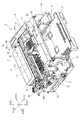
次に、図3から図6を参照してキャリッジ45、キャリッジ移動機構50およびキャリッジ昇降機構52を詳細に説明する。図3は、ケース9および排紙トレイ7を取り外したプリンター1をプリンター前方Y1の斜め上方から見た場合の斜視図である。図4は、ケース9および排紙トレイ7を取り外したプリンター1をプリンター後方Y2の斜め上方から見た場合の斜視図である。図5は、ホームポジションBに配置されたキャリッジ45を水平搬送路部分13cの側の上方から見た場合の斜視図である。図6は、アウエイポジションCの周辺を水平搬送路部分13cの側の上方から見た場合の斜視図である。
(Carriage moving mechanism)
Next, the
図3、図4に示すように、キャリッジガイド軸46およびキャリッジ支持軸47の一方の端部分は、プリンター幅方向Xの第1方向X1の端部分でプリンター前後方向Yおよび上方に延びる第1側方フレーム55に支持される。第1側方フレーム55は水平搬送路部分13cと所定の間隔を開けて配置される。キャリッジガイド軸46およびキャリッジ支持軸47の他方の端部分は、プリンター幅方向Xの第2方向X2の端部分で第1側方フレーム55と平行に延びる第2側方フレーム56に支持される。第2方向X2は第1方向X1とは反対方向である。第2側方フレーム56は水平搬送路部分13cと所定の間隔を開けて配置される。第1側方フレーム55および第2側方フレーム56は、キャリッジガイド軸46およびキャリッジ支持軸47がプリンター上下方向Zに移動可能な状態に支持する。また、第1側方フレーム55および第2側方フレーム56は、キャリッジガイド軸46およびキャリッジ支持軸47がそれらの軸線回りの回転可能な状態で支持する。
As shown in FIGS. 3 and 4, one end portion of the
キャリッジ駆動機構48は、図3に示すように、第1側方フレーム55の近傍および第2側方フレーム56の近傍にそれぞれ配置された一対のタイミングプーリー48aと、これら一対のタイミングプーリー48aに架け渡されたタイミングベルト48bを備える。タイミングベルト48bは、その一部分がキャリッジ45に固定される。キャリッジモーター49によって一方のタイミングプーリー48aを駆動させることにより、キャリッジ45はキャリッジガイド軸46およびキャリッジ支持軸47に沿って移動する。
As shown in FIG. 3, the
キャリッジ昇降機構52は、図4に示すように、キャリッジガイド軸46およびキャリッジ支持軸47の両端部分に取り付けられた偏心カム52aと、各偏心カムの外周のカム面に下方から当接するカム支持部(不図示)と昇降モーター53の駆動力をキャリッジガイド軸46およびキャリッジ支持軸47のそれぞれに伝達して、これらを軸線回りに回転させる駆動力伝達機構52bを備える。カム支持部は第1側方フレーム55および第2側方フレーム56のそれぞれに設けられる。制御部54によって昇降モーター53が駆動されると、キャリッジガイド軸46およびキャリッジ支持軸47は同期して回転する。これにより偏心カム52aが回転するので、偏心カム52aの回転に伴ってキャリッジガイド軸46およびキャリッジ支持軸47が昇降する。
As shown in FIG. 4, the
水平搬送路部分13cと第1側方フレーム55の間には印刷ヘッド12のホームポジションBが設けられる。ホームポジションBには印刷ヘッド12のメンテナンス機構57が配置される。メンテナンス機構57はヘッドキャップ58とキャップ昇降機構(不図示)を備える。ヘッドキャップ58はホームポジションBに配置された印刷ヘッド12のインクノズル面12aに対向するように配置される。キャップ昇降機構は、ホームポジションBに配置された印刷ヘッド12のインクノズル面12aに対し、ヘッドキャップ58を接近する方向および離れる方向に昇降させる。印刷ヘッド12は予め定めた一定時間を経過する毎にキャリッジ駆動機構48によってホームポジションBに配置される。図4および図5に示すように、ホームポジションBに配置された印刷ヘッド12はヘッドキャップ58に向かってインク滴を吐出させるフラッシング動作を行う。フラッシング動作は、インクの増粘などにより発生するノズルの目詰まりを解消するメンテナンス動作である。また、印刷ヘッド12は、プリンター1が待機状態となるとキャリッジ駆動機構48によってホームポジションBに配置され、ヘッドキャップ58によってそのインクノズル面12aが覆われた状態とされる。
A home position B of the
水平搬送路部分13cと第2側方フレーム56の間は、図3、図4、図6に示すように、印刷ヘッド12のアウエイポジションCである。アウエイポジションCは、印刷ヘッド12をプリンター幅方向Xに移動させながら印刷用紙Pに印刷を行う印刷動作において、印刷用紙Pの第2方向X2の端部分の印刷に際して印刷ヘッド12およびキャリッジ45の一部分を水平搬送路部分13cから外側に退避させるための空間である。印刷ヘッド12は、キャリッジ駆動機構48がキャリッジ45を移動させることにより、ホームポジションBとアウエイポジションCの間をキャリッジガイド軸46に沿って直線的に往復移動することが可能である。
Between the horizontal
(キャリッジ)
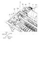
図7は、印刷ヘッド12を搭載した状態のキャリッジ45を、下方から見た場合の斜視図である。図8(a)、(b)は、紙検出器カバー73を取り外した状態のキャリッジ45を、下方から見た場合の斜視図である。図8(a)は、シャッター85が閉鎖位置85Aに配置された状態を示し、図8(b)は、シャッター85が開放位置85Bに配置された状態を示す。図9は、支軸77、紙検出器80、シャッター85および第1シャッター操作部材91および第2シャッター操作部材92の説明図である。
(carriage)
FIG. 7 is a perspective view of the
図7に示すように、キャリッジ45は、底板部60と底板部60の外周縁から上方に延びる周壁部61を備える。印刷ヘッド12は底板部60と周壁部61によって形成された凹部に上方から挿入される。底板部60には長方形の開口部62が形成される。開口部62はその長手方向がプリンター幅方向Xと一致するように設けられる。開口部62からは印刷ヘッド12のインクノズル面12aが下方に露出する。
As shown in FIG. 7, the
周壁部61は、開口部62よりもプリンター後方Y2に位置する後側周壁部分63、開口部62よりもプリンター前方Y1に位置する前側周壁部分64を備える。また、周壁部61は、後側周壁部分63と前側周壁部分64とを第1方向X1(第1側方フレーム55の側)で連続させる第1周壁部分65、および後側周壁部分63と前側周壁部分64とを第2方向X2(第2側方フレーム56の側)で連続させる第2周壁部分66を備える。後側周壁部分63には、プリンター幅方向Xに略水平に延びる筒部67が設けられる。筒部67には、キャリッジガイド軸46が挿入される。前側周壁部分64には、キャリッジ支持軸47の外周面に摺接可能な摺接部68が設けられる。
The
キャリッジ45の底板部60には、開口部62の第1方向X1の側に下方に突出する4本の紙押さえリブ70が形成される。4本の紙押さえリブ70はプリンター幅方向Xに平行に延びており、互いに等間隔に設けられる。各紙押さえリブ70の下端は開口部62から露出する印刷ヘッド12のインクノズル面12aよりも下方に位置する。各紙押さえリブ70においてプリンター幅方向Xで開口部62とは反対側に位置する先端部分には外側(第1方向X1)に向かって上方に傾斜する傾斜案内面70aが形成される。
The
キャリッジ45の底板部60において開口部62の第2方向X2の側には、紙検出器搭載部71が設けられる。図7および図8(a)、(b)に示すように、紙検出器搭載部71は、矩形の枠部72と紙検出器カバー73を備える。枠部72は、底板部60の下面から下方に向かって、一定高さで突出しており、紙検出器カバー73は、枠部72の下端開口を被うように取り付けられる。枠部72はその短手方向をプリンター幅方向Xと同一方向に向け、その長手方向をプリンター前後方向Yに向けて配置される。
A paper
図5に示すように、枠部72において、第2方向X2の端部分でプリンター前後方向Yに延びる枠部分72aには、プリンター前後方向Yに並んで形成された一対のスリットが上下に2つ設けられる。すなわち、枠部分72aには、一対の上側スリット75a、75bと、上側スリット75a、75bの下方に位置する一対の下側スリット76a、76bが設けられる。上側スリット75aおよび上側スリット75bはプリンター上下方向Zの同じ高さ位置に設けられる。また、下側スリット76aおよび下側スリット76bもプリンター上下方向Zの同じ高さ位置に設けられる。各スリット75a、75b、76a、76bはプリンター前後方向Yに細長く形成される。
As shown in FIG. 5, in the
図7に示すように、紙検出器カバー73には、矩形の検出器用開口部73aが設けられる。また、図8(a)、(b)に示すように、紙検出器搭載部71は、支軸77を備える。支軸77は、円柱形状であり、枠部72で囲まれた底板部60の下面部分から下方に向かって突出する。
As shown in FIG. 7, the
紙検出器搭載部71には、紙検出器80の検出部81(図9参照)が、配置される。プリンター上下方向Zの下方からキャリッジ45を見た場合に、検出部81と検出器用開口部73aとは、重なる位置に配置される。紙検出器80は光学式であり、図9に示すように、検出部81と回路部82を備える。検出部81は、発光部81aと受光部81bとを含んで構成される。発光部81aは、印刷位置Aに向かって検出光を射出し、受光部81bは、印刷用紙Pにより反射される検出光を受光する。検出部81においては、発光部81aの射出面及び受光部81bの受光面が、同じ方向を向くように同一平面上に配置される。回路部82は、制御部54からの指示を受けて、発光部81aを駆動して検出光を射出し、受光部81bの出力を増幅および波形成形して制御部54に伝える。
In the paper
また、紙検出器搭載部71には紙検出器80の検出部81を開閉するシャッター85が搭載される。シャッター85は、検出部81と検出器用開口部73aとの間に配置される。シャッター85は、紙検出器80の検出部81を被う閉鎖位置85Aと、検出部81を開放状態とする開放位置85Bとの間を移動可能な状態で、支軸77に支持される。図8(a)に示すように、シャッター85が、閉鎖位置85Aに配置された状態では、検出器用開口部73aは、シャッター85によって上方から閉鎖される(図7を参照)。また、図8(b)に示すように、シャッター85が、開放位置85Bに配置された状態では、シャッター85は、検出器用開口部73aから外れた位置に移動する。したがって、シャッター85が開放位置85Bに配置された状態のキャリッジ45を、下方から見た場合には、検出器用開口部73aを介して検出部81が露出する。
The paper
図9に示すように、シャッター85は、支軸77と筒部86と突出部87と第1腕部88と第2腕部89とを備える。筒部86には、支軸77が挿入され、突出部87は、筒部86から径方向の外側に直線状に突出する。第1腕部88は、突出部87の先端部分から周方向の一方側に向かって略水平に延びており、第2腕部89は、他方側に突出する。第1腕部88は、第1平板部(第1操作部)88aと傾斜平板部88bと遮蔽板部88cとを備える。第1平板部(第1操作部)88aは、突出部87と直交する方向に延びる。傾斜平板部88bは、第1平板部88aの先端から筒部86に接近する内側に折れ曲がって延在しており、その先端に、遮蔽板部88cを備える。遮蔽板部88cはシャッター85が閉鎖位置85Aに配置されたときに、検出部81と検出器用開口部73aの間に配置される部位である。第2腕部89は、突出部87から上方に向かって延びる縦板部89aと、縦板部89aの上端から第1平板部88aと反対方向に略水平に延びる第2平板部(第2操作部)89bとを備える。
As shown in FIG. 9, the
シャッター85は、支軸77を筒部86に挿入して紙検出器搭載部71に配置される。このように配置された状態では、第2腕部89の第2平板部89bは、枠部72において上方に形成される一対の上側スリット75a、75b(図5参照)のうちのプリンター前方Y1のスリット75aに対向する位置にある。また、第1腕部88の第1平板部88aは、枠部72において下方に形成される一対の下側スリット76a、76b(図5参照)のうちのプリンター後方Y2のスリット76bに対向する位置にある。
The
図6に示すように、アウエイポジションC近傍の第2側方フレーム56の内側面には、第1シャッター操作部材91および第2シャッター操作部材92が取り付けられる。第2側方フレーム56の内側面は、キャリッジ45がアウエイポジションCに配置されたときに、キャリッジ45の第2周壁部分66に対向する。第1シャッター操作部材91は、第2シャッター操作部材92よりもプリンター前方Y1に設けられる。第1シャッター操作部材91および第2シャッター操作部材92は、同一形状であり、プリンター上下方向Zにおいて、同一の高さ位置に配置される。また、第1シャッター操作部材91および第2シャッター操作部材92は、第1方向X1に向かって突出する平板であり、キャリッジ45の枠部72に形成される一対のスリット75a、75b、または、一対のスリット76a、76bに挿入可能である。
As shown in FIG. 6, a first
ここで、キャリッジ駆動機構48は、制御部54によるキャリッジモーター49の駆動制御によって駆動される。印刷動作に際しては、キャリッジ駆動機構48は、水平搬送路部分13cを搬送される印刷用紙Pの範囲において、キャリッジ45を移動させる。そのとき、キャリッジ駆動機構48は、キャリッジ45を、印刷用紙Pからプリンター幅方向Xの外側に外れないように制御する。一方、シャッター85の開閉に際しては、キャリッジ駆動機構48は、キャリッジ45をアウエイポジションCに配置する。
Here, the
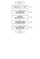
(シャッターの開閉動作)
図10は、シャッター85を開閉する開閉動作のフローチャートである。図11は、シャッター85を開閉する開閉動作の説明図である。図11(a)の左側の図は、第1位置45Aに位置したキャリッジ45が、アウエイポジションCに配置される直前の状態を示す。前述したように、第1位置45Aは、キャリッジ昇降機構52により、プラテン51と印刷ヘッド12の間のギャップが、第1距離となるキャリッジ45のZ方向の位置である。図11(a)の右側の図は、第1シャッター操作部材91が、シャッター85を操作した状態を示す。図11(b)の左側の図は、第2位置45Bに位置したキャリッジ45が、アウエイポジションCに配置される直前の状態を示す。第2位置45Bは、プラテン51と印刷ヘッド12の間のギャップが、第1距離よりも大きい第2距離となるキャリッジ45のZ方向の位置である。図11(b)の右側の図は、第2シャッター操作部材92が、シャッター85を操作した状態を示す。本例のプリンター1では、図7、図8(a)に示すように、シャッター85は、通常は、閉鎖位置85Aに配置される。
(Shutter opening / closing operation)
FIG. 10 is a flowchart of an opening / closing operation for opening / closing the
プリンター1に外部の機器から印刷データが供給されると、制御部54は、印刷データに基づいて印刷処理を行う。本実施形態では、印刷用紙Pの表面に予め設定された印刷対象領域に対して、位置精度の高い高精度印刷処理を行うための印刷データが供給されたものとする。高精度印刷処理を行うための印刷データには、第1搬送方向M1における印刷用紙Pの前端の位置および印刷用紙Pのプリンター幅方向Xの両端の位置を検出することを命令する用紙位置検出コマンドが含まれる。
When print data is supplied to the
用紙位置検出コマンドの供給を受ける(図10のステップST1)と、制御部54は、シャッター85を開く。すなわち、制御部54は、昇降モーター53を駆動して、キャリッジ45を第1位置45Aに移動させる(図10のステップST2)。その後、制御部54は、キャリッジモーター49を駆動して、キャリッジ45をアウエイポジションCに配置する(図10のステップST4)。
When receiving the paper position detection command (step ST1 in FIG. 10), the
図11(a)に示すように、キャリッジ45が、アウエイポジションCに配置される際には、まず、第1シャッター操作部材91および第2シャッター操作部材92が、一対の上側スリット75a、75bに挿入される。そして、キャリッジ45が、アウエイポジションCに完全に配置される前に、第1シャッター操作部材91が、シャッター85の第2腕部89の第2平板部89bに当接する。その後、キャリッジ45が、アウエイポジションCへ移動するのに伴って、シャッター85が、閉鎖位置85Aから開放位置85Bに移動する。すなわち、第1シャッター操作部材91とシャッター85とが当接した後に、キャリッジ45が、アウエイポジションCへ移動(第2方向X2へ移動)することによって、第1シャッター操作部材91が、シャッター85の第2腕部89を第1方向X1に押して、支軸77を中心にして、シャッター85を第1回転方向R1に回動させる。そして、キャリッジ45が、アウエイポジションCに配置された時点で、シャッター85は、開放位置85Bに配置された状態となる。
As shown in FIG. 11A, when the
ここで、シャッター85が、閉鎖位置85Aから開放位置85Bに移動する際には、第1シャッター操作部材91は、シャッター85の筒部86とキャリッジ45の支軸77との間に働く摩擦力に抗して、シャッター85を移動させる。従って、シャッター85が、開放位置85Bに配置された後には、シャッター85は、シャッター85の筒部86とキャリッジ45の支軸77との間に働く摩擦力によって、開放位置85Bに維持される。すなわち、シャッター85における筒部86の内周面86a(キャリッジ45との摺接部:図9参照)およびキャリッジ45における支軸77の外周面77a(シャッター85との摺接部:図9参照)は、摩擦面とされており、シャッター85の位置を維持する位置維持機構93として機能する。
Here, when the
その後、制御部54は、キャリッジモーター49を駆動して、キャリッジ45を水平搬送路部分13cの上方に配置する。しかる後に、制御部54は、給紙モーター24と搬送モーター36を駆動して、印刷用紙Pを用紙カセットから印刷位置Aに搬送する。
Thereafter, the
ここで、印刷用紙Pが、印刷位置Aに達すると、紙検出器80によって印刷用紙Pの先端が検出される。よって、制御部54は、印刷位置Aにおいて、搬送路13上における印刷用紙Pの先端の位置を把握できる。また、印刷用紙Pの先端が検出されると、制御部54は、キャリッジモーター49を駆動して、キャリッジ45をプリンター幅方向Xに移動させる。これにより、検出部81は、印刷用紙Pのプリンター幅方向Xにおける両端を検出することができる。したがって、制御部54は、印刷位置Aにおいて搬送路13上における印刷用紙Pの紙幅方向の両端の位置を把握できる。
Here, when the printing paper P reaches the printing position A, the
制御部54が、印刷用紙Pの紙幅方向の両端の位置を把握すると、制御部54は、シャッター85を閉鎖位置85Aに戻す動作を行う(図10のステップST1)。すなわち、制御部54は、昇降モーター53を駆動して、キャリッジ45を第1位置45Aから第2位置45Bに上昇させる(図10のステップST3)。その後、制御部54は、キャリッジモーター49を駆動して、キャリッジ45をアウエイポジションCに移動させる(図10のステップST4)。
When the
図11(b)に示すように、キャリッジ45が、アウエイポジションCに配置される際には、まず、第1シャッター操作部材91および第2シャッター操作部材92が、一対の下側スリット76a、76bに挿入される。次に、キャリッジ45が、アウエイポジションCに完全に配置される前に、第2シャッター操作部材92が、シャッター85の第1腕部88の第1平板部88aに当接する。その後、キャリッジ45が、アウエイポジションCへ移動するのに伴って、シャッター85が、開放位置85Bから閉鎖位置85Aに移動する。すなわち、第2シャッター操作部材92とシャッター85とが当接した後に、キャリッジ45がアウエイポジションCへ移動(第2方向X2へ移動)することにより、第2シャッター操作部材92が、シャッター85の第1腕部88を第1方向X1に押して、支軸77を中心にして、シャッター85を第2回転方向R2に回動させる。そして、キャリッジ45が、アウエイポジションCに配置された時点で、シャッター85は、閉鎖位置85Aに配置された状態となる。
As shown in FIG. 11B, when the
ここで、シャッター85が、開放位置85Bから閉鎖位置85Aに移動する際には、第2シャッター操作部材92は、シャッター85の筒部86とキャリッジ45の支軸77との間に働く摩擦力に抗して、シャッター85を移動させる。従って、シャッター85が、閉鎖位置85Aに配置された後には、シャッター85は、シャッター85の筒部86とキャリッジ45の支軸77との間に働く摩擦力によって、閉鎖位置85Aに維持される。すなわち、シャッター85における筒部86の内周面86a(キャリッジ45との摺接部)およびキャリッジ45における支軸77の外周面77a(シャッター85との摺接部)は、摩擦面とされており、シャッター85の位置を維持する位置維持機構93として機能する。
Here, when the
(印刷動作)
その後、印刷データに基づいて、印刷処理が行われる。制御部54は、キャリッジモーター49を駆動して、キャリッジ45を水平搬送路部分13cの上方に配置する。次に、制御部54は、印刷データに含まれる印刷用紙Pの用紙種類に基づいて、昇降モーター53を駆動制御してキャリッジ45を昇降させ、印刷ヘッド12とプラテン51との間のギャップを第1距離または第2距離に設定する。その後、制御部54は、印刷ヘッド12、キャリッジモーター49および搬送モーター36を駆動して、印刷位置Aを通過する印刷用紙Pの表面に印刷処理を行う。印刷処理は、紙検出器80によって検出させた搬送路13上における印刷用紙Pの正確な位置に基づいて行われる。すなわち、印刷ヘッド12をプリンター幅方向Xに移動させながら印刷用紙Pに向かってインク滴を吐出する印刷動作と、搬送機構22によって、印刷用紙Pを所定の紙送り量ごと紙送りする紙送り動作とが交互に行われる。印刷処理が終了すると、制御部54は、更に搬送モーター36を駆動して印刷用紙Pを排紙口8から排出する。
(Printing operation)
Thereafter, a printing process is performed based on the print data. The
(作用効果)
第1実施形態によれば、プリンター1が、キャリッジ45に搭載された紙検出器80の検出部81を被うシャッター85を備える。したがって、シャッター85が検出部81を被うことによって、印刷ヘッド12から吐出されたインク滴の一部が、印刷用紙Pに達するまでの間にインクミストとなってケース9内を浮遊する場合でも、検出部81へのインクミストの付着が抑制される。よって、プリンター1は、紙検出器80の検出部81へのインクミストの付着を抑制するために、インクミストを捕捉するための構成を備える必要がない。また、キャリッジ45に搭載されたシャッター85が、シャッター操作部材91,92と当接することによって移動されて、検出部81を開閉する。したがって、シャッター85を開閉する機構を簡易なものとすることができ、シャッター85を開閉するための駆動源を新たに備える必要がない。
(Function and effect)
According to the first embodiment, the
さらに、第1実施形態によれば、制御部54が、キャリッジ45を第1位置45Aまたは第2位置45Bに配置し、その後に、キャリッジ45をアウエイポジションCに配置することによって、シャッター85を開閉することが可能である。このため、シャッター85を開閉するためのシャッター操作部材91,92を、キャリッジ45の移動範囲におけるプリンター幅方向Xの両側に配置せず、一方側に配置することで、シャッター85を開放位置85Bと閉鎖位置85Aの間で変位させることができる。
Furthermore, according to the first embodiment, the
さらに、第1実施形態によれば、シャッター85は、キャリッジ45の移動によって開閉されるため、シャッター85を開閉する専用のアクチュエーターなどの駆動機構を搭載する必要がない。また、シャッター85は、シャッター85の筒部86とキャリッジ45の支軸77との間に働く摩擦力によって、閉鎖位置85Aまたは開放位置85Bに維持される。そのため、シャッター85の位置を維持するために特別な位置維持機構93を設ける必要がない。
Furthermore, according to the first embodiment, since the
(第1変形例)
上記の実施形態では、シャッター85における筒部86の内周面86aと、キャリッジ45における支軸77の外周面77aとを位置維持機構93として、これらの間に働く摩擦力によりシャッター85の位置を維持する。しかし、位置維持機構93は、これに限られない。位置維持機構93として、キャリッジ45およびシャッター85の一方に設けた突起と、突起と係合するためにキャリッジ45およびシャッター85の他方に設けた凹部とを備えるクリック機構を搭載してもよい。この場合には、クリック機構を、シャッター85とキャリッジ45の底板部60との間、または、シャッター85と紙検出器カバー73との間に構成することができる。
(First modification)
In the above-described embodiment, the inner
(第2変形例)
また、上記の実施形態では、キャリッジ昇降機構52は、キャリッジガイド軸46およびキャリッジ支持軸47を昇降させることにより、キャリッジ45を昇降させる。しかしながら、キャリッジ昇降機構52として、位置が固定されたキャリッジガイド軸46およびキャリッジ支持軸47上において、キャリッジ45を昇降させる機構を用いることもできる。
(Second modification)
In the above embodiment, the
(第3変形例)
また、シャッター85の形状を上記の実施形態から変更することによって、制御部54が、キャリッジ45を第1位置45Aに配置してアウエイポジションCに移動させたときに、シャッター85を開放位置85Bから閉鎖位置85Aに移動させるようにしてもよい。この場合は、制御部54が、キャリッジ45を第2位置45Bに配置してアウエイポジションCに移動させたときに、シャッター85は閉鎖位置85Aから開放位置85Bに移動させるように構成するのがよい。
(Third Modification)
Further, by changing the shape of the
(第2実施形態)
次に、図1〜図4および図12〜図17を参照して、本発明を適用したプリンター1の他の実施形態を説明する。
(Second Embodiment)
Next, another embodiment of the
図12は、第2実施形態において、印刷ヘッド12を搭載した状態のキャリッジを、下方から見た斜視図である。図13(a)、(b)は、紙検出器カバー73を取り外した状態のキャリッジ45を、下方から見た場合の斜視図である。図13(a)は、シャッター185が閉鎖位置185Aに配置された状態を示し、図13(b)は、シャッター185が開放位置185Bに配置された状態を示す。図14は、シャッター185およびシャッター操作部材210の説明図である。図15は、ホームポジションBに移動したときのキャリッジ45を、上方から見た斜視図である。図16は、シャッターオープンポジションD(後述)に移動したときのキャリッジ45を上方から見た斜視図である。図17は、シャッターの開閉動作および紙位置検出動作のフローチャートである。なお、図12〜図17において、第1実施形態と同様な構成および内容については、符号を等しくして説明を省略する。
FIG. 12 is a perspective view of the carriage mounted with the
図3、図4に示すように、アウエイポジションCと第2側方フレーム56の間には、さらにシャッターオープンポジションDが存在する。詳細は後述するが、シャッターオープンポジションDは、キャリッジ45に配置されたシャッター185(図12〜図14参照)を、閉鎖位置185Aから開放位置185Bに移動するための位置である。キャリッジ45は、キャリッジ駆動機構48(図2参照)の駆動により、アウエイポジションCに配置された後、さらにキャリッジ駆動機構48が駆動されることにより、シャッターオープンポジションDに配置される。
As shown in FIGS. 3 and 4, a shutter open position D further exists between the away position C and the
図12および図13(a)、(b)に示すように、紙検出器搭載部71には、紙検出器80の検出部81を開閉するシャッター185が搭載される。シャッター185は、検出部81と検出器用開口部73aとの間に配置される。シャッター185は、紙検出器80の検出部81を被う閉鎖位置185Aと、検出部81を開放状態とする開放位置185Bとの間を移動可能な状態で、支軸77に支持される。図13(a)に示すように、シャッター185が、閉鎖位置185Aに配置された状態では、検出器用開口部73aは、シャッター185によって上方から閉鎖される(図12参照)。また、図13(b)に示すように、シャッター185が、開放位置185Bに配置された状態では、シャッター185は、検出器用開口部73aから外れた位置に移動する。したがって、シャッター185が開放位置185Bに配置された状態のキャリッジ45を、下方から見た場合には、検出器用開口部73aを介して検出部81が露出する。
As shown in FIGS. 12, 13 (a), and 13 (b), the paper
図14に示すように、シャッター185は、突出部187と第1腕部188と第2腕部189と第3腕部190とにより構成される。突出部187は、支軸77から径方向の外側に直線状に突出しており、突出部187の端部からは、第1腕部188と第2腕部189と第3腕部190とが延びる。第1腕部188は、支軸77の周方向の一方側に向かって略水平に延びる第1平板部188aと、第1平板部188aの先端から支軸77に接近する内側に折れ曲がって延びる傾斜平板部188bと、傾斜平板部188bの先端に設けられた遮蔽板部188cとを備える。遮蔽板部188cは、シャッター185が閉鎖位置185Aに配置されたときに、検出部81と検出器用開口部73aの間に配置される部位である。第2腕部189は、第1腕部188の反対側に向かって略水平に延びる第2平板部189aと、第2平板部189aの端部から支軸77の軸方向に延びる円柱部189bとを備える。円柱部189bは、後述のシャッター操作部材210と摺接する部位である。第3腕部190は、第1腕部188と第2腕部189との接合部から支軸77の径方向の外側に向かって略水平に延びる傾斜平板であり、第1腕部188側から第2腕部189側に傾斜して延びる。また、第3腕部190は、第2実施形態において、第3のシャッター操作部材としての機能を果たす。
As shown in FIG. 14, the
また、第4のシャッター操作部材としてのシャッター操作部材210は、長形の平板部材である。シャッター操作部材210は、長手方向の一方の端に、長手方向に延在する第1の当接部210aを備え、他方の端に、第2の当接部210bを備える。第2の当接部210bは、シャッター操作部材210の端部において、長手方向と直交する方向に延在する突出部であり、その突出部分は平板部よりも肉厚である。第2の当接部210bは、シャッター185の円柱部189bと摺接する部位である。また、シャッター操作部材210は、長手方向に並行して直線部が形成された二つの長穴215を備え、長穴215を貫通する位置規制ピン220によって、キャリッジ45の往復移動方向に移動可能にキャリッジ45に設置される(図12、図13(a)、(b)参照)。
The
(シャッター操作部材の作用)
図13(a)は、シャッター185が、閉鎖位置185Aに配置された状態を示す。第1の当接部210aが、矢印F2の力によって、プリンター幅方向Xの第2方向X2に押されると、シャッター操作部材210は、長穴215と位置規制ピン220によって規制される範囲において、第2方向X2に寄る。そのため、シャッター185の円柱部189bが、シャッター操作部材210の第2の当接部210bに摺接して押され、シャッター185は、閉鎖位置185Aに配置される。
(Operation of shutter operation member)
FIG. 13A shows a state where the
図13(b)は、シャッター185が、開放位置185Bに配置された状態を示す。第3のシャッター操作部材としての第3腕部190が、矢印F1の力によって、プリンター幅方向Xの第1方向X1に押されると、シャッター185が、支軸77を中心にして、プリンター前後方向Yの前方Y1方向に回動する。これにより、第2の当接部210bが、第3腕部190と一体化した円柱部189bに摺接して押されるため、シャッター操作部材210は、長穴215と位置規制ピン220によって規制される範囲において、プリンター幅方向Xの第1方向X1に配置される。
FIG. 13B shows a state in which the
図15は、ホームポジションBに移動したときのキャリッジ45を、上方から見た斜視図である。シャッター操作部材210の第1の当接部210aは、ホームポジションBにおいて、キャリッジに対向する固定部材としてのプリンター1の第1側方フレーム55に当接する。したがって、キャリッジ45が第1方向X1に移動すると、当接部210aが第1側方フレーム55に押されて、シャッター操作部材210は、第2方向X2に移動する(図13(a)参照)。
FIG. 15 is a perspective view of the
また、図16は、シャッターオープンポジションDに移動したときのキャリッジ45を、上方から見た斜視図である。シャッター185の第3腕部190は、シャッターオープンポジションDにおいて、キャリッジに対向する他の固定部材としてのプリンター1の第2側方フレーム56の突起部56aに当接する。したがって、キャリッジ45が、第2方向X2に移動すると、第3腕部190が、第2側方フレーム56の突起部56aに押されて、シャッター185が、Y1方向に回動する。このとき、円柱部189bに押されて、シャッター操作部材210は、第1方向X1に移動する(図13(b)参照)。
FIG. 16 is a perspective view of the
(シャッターの開閉動作および紙位置検出動作)
図17は、シャッター185の開閉動作および紙位置検出動作のフローチャートである。プリンター1に外部の機器(図示しないホスト装置)から印刷データが供給されると、制御部54は、印刷データに基づいて印刷処理を行う。本実施形態では、印刷用紙Pの表面に予め設定された印刷対象領域に対して、位置精度の高い高精度印刷処理を行うための印刷データが供給されたものとする。以下、図17に基づいて、シャッター185の開閉動作および紙位置検出動作を順次説明する。
(Shutter opening / closing operation and paper position detection operation)
FIG. 17 is a flowchart of the opening / closing operation of the
ステップST1:高精度印刷処理を行うための印刷データには、第1搬送方向M1における印刷用紙Pの前端の位置および印刷用紙Pのプリンター幅方向Xの両端の位置を検出することを命令する用紙位置検出コマンドが含まれる。したがって、制御部54は、印刷データとともに用紙位置検出コマンドを受信する。
Step ST1: Paper for instructing to detect the positions of the front end of the print paper P in the first transport direction M1 and the positions of both ends of the print paper P in the printer width direction X in the print data for performing high-precision print processing A position detection command is included. Therefore, the
ステップST2:用紙位置検出コマンドの供給を受けると、制御部54は、キャリッジ移動機構50を駆動して、キャリッジ45をシャッターオープンポジションDに移動させる。キャリッジ45が、シャッターオープンポジションDに移動する際に、シャッター185の第3腕部190が、プリンター1の第2側方フレーム56の突起部56aに当接し押される(図16参照)。その結果、シャッター185が、支軸77を中心にして前方Y1方向に回動する(図13(b)参照)。このため、紙検出器80の検出部81を被っていたシャッター185の遮蔽板部188cが、開放位置185Bに移動して、検出部81が開放される。このとき、円柱部189bに押されて、シャッター操作部材210は、第1方向X1に移動する。
Step ST2: Upon receipt of the paper position detection command, the
ここで、図12に示すように、第1腕部188に設置された摺動突起195と紙検出器カバー73の内面とは、互いに摺接する。したがって、シャッター185が、閉鎖位置185Aから開放位置185Bに移動される際には、シャッター185は、摺動突起195と紙検出器カバー73の内面との間に働く摩擦力に抗して動く。そのため、シャッター185が、開放位置185Bに移動された後には、シャッター185は、摺動突起195と紙検出器カバー73の内面との間に働く摩擦力によって、開放位置185Bに維持される。すなわち、摺動突起195の上面および紙検出器カバー73の内面は、摩擦面とされており、シャッター185の位置を維持する位置維持機構93として機能する。
Here, as shown in FIG. 12, the sliding
ステップST3:ステップST2において紙検出器80を被っていたシャッター185が開かれた後、制御部54は、キャリッジモーター49を駆動して、キャリッジ45を水平搬送路部分13cの上方に配置して、紙検出器80をON(検出可能状態)とする。すなわち、発光部81aから印刷用紙Pに向かって検出光を射出するとともに、受光部81bを受光可能状態にセットする。
Step ST3: After the
ステップST4:制御部54は、給紙モーター24と搬送モーター36を駆動して、印刷用紙Pを用紙カセットから印刷位置Aに搬送する。ここで、印刷用紙Pが印刷位置Aに達すると、発光部81aから射出された検出光を印刷用紙Pが反射するので、受光部81bは検出光を検出する。したがって、受光部81bによる検出光の検出の有無に基づいて、印刷用紙Pの有無が検出されるので、印刷用紙Pの先端が検出できる。回路部82は、受光部81bの検出出力を増幅および波形成形をして制御部54に出力する。このため、制御部54は、印刷位置Aにおいて、搬送路13上における印刷用紙Pの先端の位置を把握できる。また、印刷用紙Pの先端が検出されると、制御部54は、キャリッジモーター49を駆動して、キャリッジ45をプリンター幅方向Xに移動させながら、受光部81bに検出光の有無を検出させる。これにより、検出部81が、プリンター幅方向Xにおける印刷用紙Pの有無を検出することができるので、制御部54は、印刷位置Aにおいて、搬送路13上における印刷用紙Pの紙幅方向の両端の位置を把握できる。
Step ST4: The
ステップST5:制御部54は、紙検出器80をOFF(非検出状態)に戻し、キャリッジ移動機構50を駆動して、キャリッジ45をホームポジションBに移動させる。キャリッジ45が、ホームポジションBに移動する際に、シャッター操作部材210の第1の当接部210aが、プリンター1の第1側方フレーム55に当接し押される(図15参照)。それに伴い、シャッター操作部材210の第2の当接部210bが、シャッター185の円柱部189bに摺接して、支軸77を中心にして、シャッター185を後方Y2方向に回動させる。その結果、シャッター185が、閉鎖位置185Aに配置され、紙検出器80の検出部81を被う(図13(a)参照)。
Step ST5: The
ここで、シャッター185が、開放位置185Bから閉鎖位置185Aに移動する際には、上述した閉鎖位置185Aから開放位置185Bに移動する際と同様に、シャッター185は、第1腕部188に設置された摺動突起195と紙検出器カバー73の内面との間に働く摩擦力に抗して移動する。したがって、シャッター185が、閉鎖位置185Aに移動された後には、シャッター185は、摺動突起195と紙検出器カバー73の内面との間に働く摩擦力によって、閉鎖位置185Aに維持される。
Here, when the
以上のように、制御部54は、ホスト装置からの指令に基づいて、キャリッジ45をシャッターオープンポジションDに移動させて、シャッター185を開き、その後紙検出器80による印刷用紙Pの紙端検出を行なう。そして、紙端検出の終了後、キャリッジ45をホームポジションBに移動させてシャッター185を閉じ、紙検出80の検出部81を被う。すなわち、印刷用紙Pの紙端検出は、シャッター185が開かれて、紙検出器80の検出部81が、開放されたときに実施される。
As described above, the
(印刷動作)
その後、印刷データに基づいて、前述の第1実施形態と同様の印刷処理が行われる。
(Printing operation)
Thereafter, based on the print data, the same printing process as in the first embodiment is performed.
(作用効果)
第2実施形態によれば、プリンター1が、キャリッジ45に搭載された紙検出器80の検出部81を被うシャッター185を備える。したがって、シャッター185が検出部81を被うことによって、印刷ヘッド12から吐出されたインク滴の一部が、印刷用紙Pに達するまでの間にインクミストとなってケース9内を浮遊する場合でも、検出部81へのインクミストの付着を抑制できる。したがって、紙検出器80の検出部81へのインクミストの付着を抑制するために、インクミストを捕捉するファンおよびフィルターといった構成を備える必要がない。その結果、それらを配置するスペースが不要となるので、装置の小型化を図ることができ、製造コストの増加も抑えることができる。
(Function and effect)
According to the second embodiment, the
さらに、第2実施形態では、シャッター185は、シャッター185上の摺動突起195と紙検出器カバー73との間に働く摩擦力によって、閉鎖位置185Aまたは開放位置185Bに維持される。そのため、簡単な構造でシャッター185の位置維持機構93を構成できる。
Furthermore, in the second embodiment, the
(第4変形例)
なお、第2実施形態では、用紙位置検出コマンドは、印刷データに含まれて制御部54に送出されたが、印刷データとは別途、任意のタイミングで外部の機器(図示しないホスト装置)から制御部54に送出されてもよい。
(Fourth modification)
In the second embodiment, the paper position detection command is included in the print data and sent to the
(第5変形例)
また、紙検出器カバー73の内面とともに位置維持機構93を構成する摺動突起195は、突出部187に設置されてもよい。また、摺動突起195は、第1腕部188または突出部187のキャリッジ45に対向する面(紙検出器カバー73に対向する面の反対側の面)に設置されていてもよい。この場合は、摺動突起195は、キャリッジ45に対して摺動し、シャッター185は、摺動突起195とキャリッジ45との間に働く摩擦力によって、開放位置185Bに維持される。また、摺動突起195を持たずに、第1腕部188または突出部187が、紙検出器カバー73の内面またはキャリッジ45と摺動するように構成してもよい。
(5th modification)
In addition, the sliding
(第6変形例)
さらに、位置維持機構93として、キャリッジ45およびシャッター185の一方に設けた突起と、突起と係合するためにキャリッジ45およびシャッター185の他方に設けた凹部とを備えるクリック機構を搭載してもよい。この場合には、クリック機構を、シャッター185とキャリッジ45の底板部60との間、または、シャッター185と紙検出器カバー73との間に構成することができる。
(Sixth Modification)
Furthermore, as the
(第7変形例)
また、シャッター操作部材210は、長形の平板部材に限らず、丸棒や角棒といった棒状部材で構成してもよいし、平板部材と棒状部材を組み合わせて構成してもよい。
(Seventh Modification)
The
(第8変形例)
図18は、シャッター185およびシャッター操作部材210の変形例(第8変形例)を説明する図である。以下に、図18を参照して、第8変形例のシャッター385およびシャッター操作部材410を説明する。なお、図18において、第1実施形態と同様な構成および内容については、符号を等しくして説明を省略する。
(Eighth modification)
FIG. 18 is a diagram illustrating a modified example (eighth modified example) of the
図18に示すように、シャッター385は、第3のシャッター操作部材としての第3腕部190に相当する部位を備えないことを除けば、第2実施形態のシャッター185の構造(図14参照)と同一である。したがって、シャッター385の各部位である387,388,388a,388b,388c,389,389a,389b,395は、シャッター185の各部位である187,188,188a,188b,188c,189,189a,189b,195に相当する。また、シャッター操作部材410は、長形の平板部材で形成されること、長手方向に延在する第1の当接部410aを備えること、二つの長穴415を備えることについて、第2実施形態のシャッター操作部材210(図14参照)の構造と同一である。それに加えて、シャッター操作部材410は、長手方向に直交する方向に突出する2つの第2の当接部410bと第3の当接部410cを備える。第2の当接部410bは、互いに並行して延在し、平板部よりも肉厚に形成される。2つの第2の当接部410bは、その間に、シャッター385の円柱部389bを挟み込んで摺接する。また、第3の当接部410cは、本変形例において、第3のシャッター操作部材としての機能を果たす。したがって、本変形例のシャッター操作部材410は、第3のシャッター操作部材および第4のシャッター操作部材を、一部材で構成して機能する共通操作部材である。
As shown in FIG. 18, the
(シャッター操作部材の作用とシャッターの開閉動作)
キャリッジ45が、シャッターオープンポジションDに移動されると、シャッター操作部材410の第3の当接部410cが、プリンター1の第2側方フレーム56に当接することにより、シャッター操作部材410が第1方向X1に移動する。すると、シャッター操作部材410の2つの第2の当接部410bが、シャッター385の円柱部389bを挟み込んで摺接するため、シャッター385は、支軸77を中心にして回動する。その結果、紙検出器80の検出部81を被っていたシャッター385の遮蔽板部388cが、第2方向X2に移動して、検出部81が開放される。
(Operation of shutter operation member and opening / closing operation of shutter)
When the
キャリッジ45が、ホームポジションBに移動されると、シャッター操作部材410の第1の当接部410aが、プリンター1の第1側方フレーム55に当接することによって、シャッター操作部材410が、第2方向X2に移動する。すると、シャッター操作部材410に摺接したシャッター385は、支軸77を中心にして回動して、遮蔽板部388cが、第1方向X1に移動して紙検出器80の検出部81を被い、検出部81が閉鎖される。
When the
(第9変形例)
なお、第8変形例のシャッター385およびシャッター操作部材410を適用したプリンター1においても、上述の第4変形例〜第7変形例のように変形することができる。
(Ninth Modification)
Note that the
(第3実施形態)
次に、図1〜図4および図19〜図22を参照して、本発明を適用したプリンター1のさらに他の実施形態を説明する。
(Third embodiment)
Next, still another embodiment of the
図19は、第3実施形態において、印刷ヘッド12を搭載した状態のキャリッジを、下方から見た斜視図である。図20(a)、(b)は、紙検出器カバー73を取り外した状態のキャリッジ45を、下方から見た場合の斜視図である。図20(a)は、シャッター285が閉鎖位置285Aに配置された状態を示し、図20(b)は、シャッター285が開放位置285Bに配置された状態を示す。図21は、シャッター285およびシャッター移動機構290の説明図である。図22は、シャッターの開閉動作および紙位置検出動作のフローチャートである。なお、図19〜図22において、第1実施形態と同様な構成および内容については、符号を等しくして説明を省略する。
FIG. 19 is a perspective view of the carriage on which the
図19および図20(a)、(b)に示すように、紙検出器搭載部71には紙検出器80の検出部81を開閉するシャッター285が搭載される。シャッター285は、検出部81と検出器用開口部73aの間に配置される。シャッター285は、紙検出器80の検出部81を被う閉鎖位置285Aと、検出部81を開放状態とする開放位置285Bとの間を移動可能な状態で、支軸277に支持される。図20(a)に示すように、シャッター285が、閉鎖位置285Aに配置された状態では、検出器用開口部73aは、シャッター285によって上方から閉鎖される(図19参照)。また、図20(b)に示すように、シャッター285が、開放位置285Bに配置された状態では、シャッター285は、検出器用開口部73aから外れた位置に移動する。したがって、シャッター285が開放位置285Bに配置された状態のキャリッジ45を、下方から見た場合には、検出器用開口部73aを介して検出部81が露出する。
As shown in FIGS. 19, 20 (a), and 20 (b), the paper
図21に示すように、シャッター285は、支軸277から径方向の外側に直線状に突出する突出部287と、突出部287の端部から周方向の一方側に向かって略水平に延びる第1腕部288とにより構成される。第1腕部288は、突出部287と直交する方向に延びる第1平板部288aと、第1平板部288aの先端から支軸277に接近する内側に折れ曲がって延びる傾斜平板部288bと、傾斜平板部288bの先端に設けられた遮蔽板部288cとを備える。遮蔽板部288cはシャッター285が閉鎖位置285Aに配置されたときに、検出部81と検出器用開口部73aの間に配置される部位である。また、突出部287の第1腕部288とつながる端部と相対する位置の端部には、電動アクチュエーター286の回転軸に固定された支軸277が備わる。電動アクチュエーター286は、シャッター移動機構290を成す駆動源である。電動アクチュエーター286の回転軸に固定されたシャッター285の支軸277は、シャッター移動機構290を成す伝達機構である。そして、電動アクチュエーター286が、正転駆動または逆転駆動することにより、シャッター285が、閉鎖位置285Aと開放位置285Bの間を移動する。
As shown in FIG. 21, the
また、シャッター移動機構290は、この構成に限らない。つまり、回転動作型の電動アクチュエーター286を、シャッター285の支軸277と位置をずらせて配置してもよい。その場合は、輪列などを伝達機構として用いて駆動力をシャッター85に伝え、シャッター285を回動させることもできる。また、回転動作型の電動アクチュエーターではなくリニアモーターを使用して、回転軸を備えたシャッターを回動させてもよい。また、リニアモーターを使用して、スライド移動可能な構造のシャッターを、直接前進後退移動させてもよい。この場合は、シャッター移動機構290は、伝達機構を必要とせず、駆動源のリニアモーターだけで構成可能となる。
Further, the
(シャッターの開閉動作および紙位置検出動作)
図22は、シャッター285の開閉動作および紙位置検出動作のフローチャートである。プリンター1に、外部の機器(図示しないホスト装置)から印刷データが供給されると、制御部54は、印刷データに基づいて印刷処理を行う。本実施形態では、印刷用紙Pの表面に予め設定された印刷対象領域に対して、位置精度の高い高精度印刷処理を行うための印刷データが、供給されたものとする。以下、図22に基づいて、シャッター285の開閉動作および紙位置検出動作を順次説明する。
(Shutter opening / closing operation and paper position detection operation)
FIG. 22 is a flowchart of the opening / closing operation of the
ステップST1:高精度印刷処理を行うための印刷データには、第1搬送方向M1における印刷用紙Pの前端の位置および印刷用紙Pのプリンター幅方向Xの両端の位置を検出することを命令する用紙位置検出コマンドが含まれる。したがって、制御部54は、印刷データとともに用紙位置検出コマンドを受信する。
Step ST1: Paper for instructing to detect the positions of the front end of the print paper P in the first transport direction M1 and the positions of both ends of the print paper P in the printer width direction X in the print data for performing high-precision print processing A position detection command is included. Therefore, the
ステップST2:用紙位置検出コマンドの供給を受けると、制御部54はシャッター285を開く。すなわち、制御部54は、電動アクチュエーター286を駆動させるための駆動信号を出力する。その駆動信号を受けた電動アクチュエーター286は、回転動作を開始して、その回転軸(支軸277)に結合されたシャッター285を、閉鎖位置285Aから開放位置285Bへと回動させる。
Step ST2: Upon receipt of the paper position detection command, the
ここで、シャッター285が閉鎖位置285Aから開放位置285Bに移動する際には、シャッター285は、第1腕部288に設置された摺動突起289と紙検出器カバー73の内面との間に働く摩擦力に抗して移動する。したがって、シャッター285が開放位置285Bに移動された後には、シャッター285は、摺動突起289と紙検出器カバー73の内面との間に働く摩擦力によって、開放位置285Bに維持される。すなわち、摺動突起289の上面(紙検出器カバー73の内面との摺接部:図19、図21参照)および紙検出器カバー73の内面(摺動突起289の上面との摺接部:図19、図21参照)は、摩擦面とされており、シャッター285の位置を維持する位置維持機構93として機能する。
Here, when the
ステップST3:ステップST2において紙検出器80を被っていたシャッター285が開かれた後、制御部54は、キャリッジモーター49を駆動して、キャリッジ45を水平搬送路部分13cの上方に配置して、紙検出器80を検出可能状態とする。すなわち、発光部81aから印刷用紙Pに向かって検出光を射出するとともに、受光部81bを受光可能状態にセットする。
Step ST3: After the
ステップST4:制御部54は、給紙モーター24と搬送モーター36を駆動して、印刷用紙Pを用紙カセットから印刷位置Aに搬送する。ここで、印刷用紙Pが印刷位置Aに達すると、発光部81aから射出された検出光を印刷用紙Pが反射するので、受光部81bは検出光を検出する。したがって、受光部81bによる検出光の検出の有無に基づいて、印刷用紙Pの有無が検出されるので、印刷用紙Pの先端が検出できる。回路部82は、受光部81bの検出出力を増幅および波形成形をして制御部54に出力する。このため、制御部54は、印刷位置Aにおいて、搬送路13上における印刷用紙Pの先端の位置を把握できる。また、印刷用紙Pの先端が検出されると、制御部54は、キャリッジモーター49を駆動して、キャリッジ45をプリンター幅方向Xに移動させながら、受光部81bに検出光の有無を検出させる。これにより、検出部81が、プリンター幅方向Xにおける印刷用紙Pの有無を検出することができるので、制御部54は、印刷位置Aにおいて、搬送路13上における印刷用紙Pの紙幅方向の両端の位置を把握できる。
Step ST4: The
ステップST5:制御部54は、紙検出器80を非検出状態に戻し、シャッター285を閉鎖位置285Aに戻す。すなわち、制御部54は、電動アクチュエーター286を回動させる駆動信号を出力して、シャッター285を、開放位置285Bから閉鎖位置285Aへと旋回移動させる。
Step ST5: The
ここで、シャッター285が、開放位置285Bから閉鎖位置285Aに移動する際には、シャッター285は、第1腕部288に設置された摺動突起289と紙検出器カバー73の内面との間に働く摩擦力に抗して移動する。したがって、シャッター285が閉鎖位置285Aに移動された後には、シャッター285は、摺動突起289と紙検出器カバー73の内面との間に働く摩擦力によって、閉鎖位置285Aに維持される。すなわち、摺動突起289の上面(紙検出器カバー73の内面との摺接部:図19、図21参照)および紙検出器カバー73の内面(摺動突起289の上面との摺接部:図19、図21参照)は、摩擦面とされており、シャッター285の位置を維持する位置維持機構93として機能する。
Here, when the
以上のように、制御部54は、ホスト装置からの指令に基づいて、シャッター285を開いて、紙検出器80による印刷用紙Pの紙端検出を行ない、その後シャッター85を閉じて紙検出器80の検出部81を被う。すなわち、印刷用紙Pの紙端検出は、シャッター285が開かれて、紙検出器80の検出部81が、開放されたときに実施される。
As described above, the
(印刷動作)
その後、印刷データに基づいて、前述の第1実施形態と同様の印刷処理が行われる。
(Printing operation)
Thereafter, based on the print data, the same printing process as in the first embodiment is performed.
(作用効果)
第3実施形態によれば、プリンター1が、キャリッジ45に搭載されたシャッター285を備える。シャッター285は、シャッター移動機構290によって動かされ、紙検出器80の検出部81を被うことができる。したがって、印刷ヘッド12から吐出されたインク滴の一部が、印刷用紙Pに達するまでの間にインクミストとなってケース9内を浮遊する場合でも、検出部81へのインクミストの付着を抑制できる。そのため、プリンター1は、インクミストを捕捉するファンおよびフィルターといった構成を、備える必要がない。したがって、それらを配置するスペースが不要となるので、プリンター1の小型化を図ることができ、プリンター1の製造コストの増加も抑えることができる。
(Function and effect)
According to the third embodiment, the
また、シャッター285は、キャリッジ45に搭載されており、外部の機器(図示しないホスト装置)からコマンドを受けて、シャッター移動機構290によって移動され、検出部81を開閉する。したがって、印刷用紙Pの検出を必要とするときには、自在にシャッター85を開閉することができる。
The
さらに、第3実施形態では、シャッター285は、シャッター285上の摺動突起289と紙検出器カバー73との間に働く摩擦力によって閉鎖位置285Aまたは開放位置285Bに維持される。このため、シャッター285の位置維持機構93が、簡単な構造で構成される。
Furthermore, in the third embodiment, the
なお、用紙位置検出コマンドは、上述のように、印刷データに含まれて制御部54に送出されてもよいし、印刷データとは別途任意のタイミングで外部の機器(図示しないホスト装置)から制御部54に送出されてもよい。
As described above, the paper position detection command may be included in the print data and sent to the
また、紙検出器カバー73の内面とともに位置維持機構93を構成する摺動突起289は、突出部287に設置されてもよい。また、摺動突起289は、第1腕部288および突出部287の少なくとも一方のキャリッジ45に対向する面(紙検出器カバー73に対向する面の反対側の面)に設置されていてもよい。この場合は、摺動突起289はキャリッジ45に対して摺動し、シャッター285は、摺動突起289とキャリッジ45との間に働く摩擦力によって開放位置285Bに維持される。また、摺動突起289を持たずに、第1腕部288および突出部287の少なくとも一方が、紙検出器カバー73の内面乃至キャリッジ45と摺動するように構成してもよい。
Further, the sliding
さらに、位置維持機構93として、キャリッジ45およびシャッター285の一方に設けた突起と、突起と係合するためにキャリッジ45およびシャッター285の他方に設けた凹部とを備えるクリック機構を搭載してもよい。この場合には、クリック機構を、シャッター285とキャリッジ45の底板部60との間、または、シャッター285と紙検出器カバー73との間に構成することができる。
Furthermore, as the
1…プリンター、6…給紙カセット、8…排紙口、9…ケース、9b…操作スイッチ、12…印刷ヘッド、13…搬送路、21…給紙ローラー、22…搬送機構、23…反転用搬送機構、24…給紙モーター、36…搬送モーター、40…反転用搬送モーター、45…キャリッジ、46…キャリッジガイド軸、47…キャリッジ支持軸、48…キャリッジ駆動機構、49…キャリッジモーター、50…キャリッジ移動機構、51…プラテン、52…キャリッジ昇降機構、53…昇降モーター、54…制御部、55…第1側方フレーム、56…第2側方フレーム、60…底板部、62…開口部、71…紙検出器搭載部、73…紙検出器カバー、73a…検出器用開口部、77…支軸、80…紙検出器、81…検出部、81a…発光部、81b…受光部、82…回路部、91…第1シャッター操作部材、92…第2シャッター操作部材、85,285,185,385…シャッター、85A,185A,285A…閉鎖位置、85B,185B,285B…開放位置、88c,188c,388c…遮蔽板部、195,395…摺動突起、93…位置維持機構、210,410…シャッター操作部材、215,415…長穴、220…位置規制ピン、290…シャッター移動機構、A…印刷位置、B…ホームポジション、C…アウエイポジション、D…シャッターオープンポジション、M1…第1搬送方向、M2…第2搬送方向、P…印刷用紙。
DESCRIPTION OF
Claims (8)
インクを吐出して前記印刷用紙に印刷を行う印刷ヘッドと、
前記印刷ヘッドと対向するように設けられたプラテンと、
前記印刷ヘッドを搭載するキャリッジと、
前記第1の方向と直交する第2の方向に、前記キャリッジを移動させる第1のキャリッジ移動機構と、
前記プラテンと前記印刷ヘッドとの間のギャップが、第1の距離、又は、前記第1の距離よりも大きい第2の距離になるように、前記キャリッジを移動させる第2のキャリッジ移動機構と、
前記キャリッジに搭載され、前記印刷用紙に向けて光を発光する発光部、及び、前記印刷用紙から反射された光を検出する検出部を有する紙検出器と、
前記紙検出器の少なくとも前記検出部を覆う閉鎖位置と、前記閉鎖位置とは異なる開放位置と、を移動するシャッターと、
前記第2の方向の一方、又は、前記第2の方向の他方に設けられており、前記ギャップが前記第1の距離のときに、前記シャッターを移動させる第1のシャッター操作部材と、
前記第2の方向の一方、又は、前記第2の方向の他方に設けられており、前記ギャップが前記第2の距離のときに、前記シャッターを移動させる第2のシャッター操作部材と、を備えることを特徴とするプリンター。 A transport path for transporting printing paper in the first direction;
A print head that ejects ink to print on the printing paper;
A platen provided to face the print head;
A carriage carrying the print head;
In a second direction perpendicular to the first direction, a first carriage moving mechanism for moving the carriage,
A second carriage movement mechanism that moves the carriage so that a gap between the platen and the print head is a first distance or a second distance that is larger than the first distance;
A paper detector that is mounted on the carriage and emits light toward the printing paper ; and a detector that detects light reflected from the printing paper;
A shutter that moves between a closed position that covers at least the detection unit of the paper detector, and an open position different from the closed position;
A first shutter operating member that is provided in one of the second directions or in the other of the second directions and moves the shutter when the gap is the first distance;
One of the second direction, or, the provided on the other in the second direction, when the gap of the second distance, and a second shutter operation member for moving the shutter A printer characterized by that.
前記第1のシャッター操作部材、及び、前記第2のシャッター操作部材は、前記フレームに設けられる請求項1に記載のプリンター。 A frame facing the carriage;
The printer according to claim 1, wherein the first shutter operation member and the second shutter operation member are provided on the frame.
プラテンと対向するように設けられており、インクを吐出する印刷ヘッドと、光を発光する発光部、及び、光を検出する検出部を有する光検出器と、を搭載するキャリッジを、前記第1の方向と直交する第2の方向に移動させ、
前記プラテンと前記印刷ヘッドとの間のギャップが、第1の距離、又は、前記第1の距離よりも大きい第2の距離になるように、前記キャリッジを移動させ、
前記印刷用紙を前記光検出器で検出し、
前記ギャップが前記第1の距離にあって、前記キャリッジが、前記第2の方向の一方、又は、前記第2の方向の他方に移動したときに、少なくとも前記検出部をシャッターから開放し、
前記ギャップが前記第2の距離にあって、前記キャリッジが、前記第2の方向の一方、又は、前記第2の方向の他方に移動したときに、少なくとも前記検出部を前記シャッターで遮蔽することを特徴とするプリンターの紙位置検出方法。 Transport printing paper in the first direction,
Is provided so as to platen facing the printing head for ejecting ink, the light emitting unit for emitting light, and a light detector having a detector for detecting light, a carriage for mounting said first Moved in a second direction orthogonal to the direction of
Moving the carriage so that a gap between the platen and the print head is a first distance or a second distance greater than the first distance;
Detecting the printing paper with the photodetector;
When the gap is at the first distance and the carriage moves in one of the second directions or the other in the second direction, at least the detection unit is released from the shutter;
There the gap to the second distance, the carriage, one of the second direction, or when moved in the other of said second direction, to shield at least the detection part in the shutter A method for detecting the paper position of a printer.
Priority Applications (3)
| Application Number | Priority Date | Filing Date | Title |
|---|---|---|---|
| JP2014178820A JP6459314B2 (en) | 2013-10-11 | 2014-09-03 | Printer and printer paper position detection method |
| US14/511,949 US9296226B2 (en) | 2013-10-11 | 2014-10-10 | Printer, and paper position detection method of a printer |
| CN201410531570.3A CN104553316B (en) | 2013-10-11 | 2014-10-10 | Printer, and paper position detection method of a printer |
Applications Claiming Priority (7)
| Application Number | Priority Date | Filing Date | Title |
|---|---|---|---|
| JP2013213469 | 2013-10-11 | ||
| JP2013213469 | 2013-10-11 | ||
| JP2014141186 | 2014-07-09 | ||
| JP2014141186 | 2014-07-09 | ||
| JP2014141187 | 2014-07-09 | ||
| JP2014141187 | 2014-07-09 | ||
| JP2014178820A JP6459314B2 (en) | 2013-10-11 | 2014-09-03 | Printer and printer paper position detection method |
Publications (3)
| Publication Number | Publication Date |
|---|---|
| JP2016026906A JP2016026906A (en) | 2016-02-18 |
| JP2016026906A5 JP2016026906A5 (en) | 2017-08-10 |
| JP6459314B2 true JP6459314B2 (en) | 2019-01-30 |
Family
ID=52809307
Family Applications (1)
| Application Number | Title | Priority Date | Filing Date |
|---|---|---|---|
| JP2014178820A Expired - Fee Related JP6459314B2 (en) | 2013-10-11 | 2014-09-03 | Printer and printer paper position detection method |
Country Status (3)
| Country | Link |
|---|---|
| US (1) | US9296226B2 (en) |
| JP (1) | JP6459314B2 (en) |
| CN (1) | CN104553316B (en) |
Families Citing this family (2)
| Publication number | Priority date | Publication date | Assignee | Title |
|---|---|---|---|---|
| EP3363639B1 (en) * | 2017-02-17 | 2020-04-08 | Canon Kabushiki Kaisha | Inkjet printing apparatus |
| JP2022034950A (en) * | 2020-08-19 | 2022-03-04 | 東芝テック株式会社 | Printer |
Family Cites Families (14)
| Publication number | Priority date | Publication date | Assignee | Title |
|---|---|---|---|---|
| JPH11227176A (en) | 1998-02-19 | 1999-08-24 | Canon Inc | Scanner printer and serial printer |
| JP2001328266A (en) * | 2000-05-19 | 2001-11-27 | Olympus Optical Co Ltd | Ink jet recording apparatus |
| US6523925B1 (en) * | 2001-10-30 | 2003-02-25 | Hewlett-Packard Company | Media leading edge sensor |
| KR100657311B1 (en) * | 2005-01-26 | 2006-12-13 | 삼성전자주식회사 | Array inkjet head and inkjet image forming apparatus using the same |
| JP2007118438A (en) | 2005-10-28 | 2007-05-17 | Canon Inc | Printer |
| JP2007130802A (en) | 2005-11-08 | 2007-05-31 | Canon Inc | Inkjet recorder |
| JP4802076B2 (en) * | 2006-09-29 | 2011-10-26 | 富士フイルム株式会社 | Active energy curable ink jet recording apparatus |
| JP5171236B2 (en) * | 2007-12-14 | 2013-03-27 | キヤノン株式会社 | Recording device |
| US8137017B2 (en) * | 2008-08-27 | 2012-03-20 | Eastman Kodak Company | Selectively coupling a device to a carriage |
| JP2010062910A (en) * | 2008-09-04 | 2010-03-18 | Canon Inc | Image forming apparatus |
| JP2010064266A (en) | 2008-09-08 | 2010-03-25 | Ricoh Co Ltd | Image forming apparatus |
| JP2011016309A (en) | 2009-07-09 | 2011-01-27 | Seiko Epson Corp | Liquid ejector, recorder equipped therewith, and control method of liquid ejector |
| US8382229B2 (en) * | 2010-09-27 | 2013-02-26 | Eastman Kodak Company | Lead edge detector for printer |
| CN104070854B (en) * | 2013-03-27 | 2016-03-09 | 精工爱普生株式会社 | Printer |
-
2014
- 2014-09-03 JP JP2014178820A patent/JP6459314B2/en not_active Expired - Fee Related
- 2014-10-10 US US14/511,949 patent/US9296226B2/en active Active
- 2014-10-10 CN CN201410531570.3A patent/CN104553316B/en not_active Expired - Fee Related
Also Published As
| Publication number | Publication date |
|---|---|
| CN104553316A (en) | 2015-04-29 |
| JP2016026906A (en) | 2016-02-18 |
| US20150103127A1 (en) | 2015-04-16 |
| US9296226B2 (en) | 2016-03-29 |
| CN104553316B (en) | 2017-04-12 |
Similar Documents
| Publication | Publication Date | Title |
|---|---|---|
| JP6291854B2 (en) | Printer and control method thereof | |
| US9259937B2 (en) | Printing apparatus | |
| JP6459314B2 (en) | Printer and printer paper position detection method | |
| CN110509675B (en) | Ink jet recording apparatus | |
| US10730300B2 (en) | Inkjet printing apparatus | |
| US10766259B2 (en) | Inkjet printing apparatus operable in response to a preceding command | |
| TW201238782A (en) | Printer and printer control method | |
| JP5428974B2 (en) | Image forming apparatus | |
| JP5801043B2 (en) | Recording device | |
| US9259945B2 (en) | Printing apparatus | |
| JP5752919B2 (en) | Recording device | |
| US10099491B2 (en) | Ink-jet printer | |
| JP2005335246A (en) | Liquid jet device | |
| JP5643610B2 (en) | Recording device | |
| JP2015051575A (en) | Image forming device | |
| JP2010062910A (en) | Image forming apparatus | |
| JP7067009B2 (en) | Image recording device | |
| CN107336522B (en) | Recording apparatus | |
| JP2008238797A (en) | Image forming device | |
| JP2019171795A (en) | Recording head and recording device | |
| JP2020104460A (en) | Recording medium transport device and recording device | |
| JP2008173935A (en) | Image formation device | |
| JP2017149092A (en) | Recording device | |
| JP2015024912A (en) | Printer | |
| JP2017177659A (en) | Printer |
Legal Events
| Date | Code | Title | Description |
|---|---|---|---|
| RD03 | Notification of appointment of power of attorney |
Free format text: JAPANESE INTERMEDIATE CODE: A7423 Effective date: 20160622 |
|
| A521 | Request for written amendment filed |
Free format text: JAPANESE INTERMEDIATE CODE: A523 Effective date: 20170703 |
|
| A621 | Written request for application examination |
Free format text: JAPANESE INTERMEDIATE CODE: A621 Effective date: 20170703 |
|
| A977 | Report on retrieval |
Free format text: JAPANESE INTERMEDIATE CODE: A971007 Effective date: 20180330 |
|
| A131 | Notification of reasons for refusal |
Free format text: JAPANESE INTERMEDIATE CODE: A131 Effective date: 20180410 |
|
| A521 | Request for written amendment filed |
Free format text: JAPANESE INTERMEDIATE CODE: A523 Effective date: 20180510 |
|
| A131 | Notification of reasons for refusal |
Free format text: JAPANESE INTERMEDIATE CODE: A131 Effective date: 20180724 |
|
| RD05 | Notification of revocation of power of attorney |
Free format text: JAPANESE INTERMEDIATE CODE: A7425 Effective date: 20180904 |
|
| A521 | Request for written amendment filed |
Free format text: JAPANESE INTERMEDIATE CODE: A523 Effective date: 20180913 |
|
| RD03 | Notification of appointment of power of attorney |
Free format text: JAPANESE INTERMEDIATE CODE: A7423 Effective date: 20181107 |
|
| TRDD | Decision of grant or rejection written | ||
| A01 | Written decision to grant a patent or to grant a registration (utility model) |
Free format text: JAPANESE INTERMEDIATE CODE: A01 Effective date: 20181204 |
|
| A61 | First payment of annual fees (during grant procedure) |
Free format text: JAPANESE INTERMEDIATE CODE: A61 Effective date: 20181217 |
|
| R150 | Certificate of patent or registration of utility model |
Ref document number: 6459314 Country of ref document: JP Free format text: JAPANESE INTERMEDIATE CODE: R150 |
|
| LAPS | Cancellation because of no payment of annual fees |