JP6453777B2 - Manual and robotic hybrid interventional instruments and methods of use - Google Patents
Manual and robotic hybrid interventional instruments and methods of use Download PDFInfo
- Publication number
- JP6453777B2 JP6453777B2 JP2015561644A JP2015561644A JP6453777B2 JP 6453777 B2 JP6453777 B2 JP 6453777B2 JP 2015561644 A JP2015561644 A JP 2015561644A JP 2015561644 A JP2015561644 A JP 2015561644A JP 6453777 B2 JP6453777 B2 JP 6453777B2
- Authority
- JP
- Japan
- Prior art keywords
- drive
- coupled
- instrument
- handpiece
- input
- Prior art date
- Legal status (The legal status is an assumption and is not a legal conclusion. Google has not performed a legal analysis and makes no representation as to the accuracy of the status listed.)
- Active
Links
- 238000000034 method Methods 0.000 title description 29
- 230000033001 locomotion Effects 0.000 claims description 82
- 230000007246 mechanism Effects 0.000 claims description 63
- 238000003780 insertion Methods 0.000 description 28
- 230000037431 insertion Effects 0.000 description 28
- 238000004804 winding Methods 0.000 description 23
- 239000000835 fiber Substances 0.000 description 17
- 239000013307 optical fiber Substances 0.000 description 16
- 238000003384 imaging method Methods 0.000 description 13
- 210000003484 anatomy Anatomy 0.000 description 11
- 230000008878 coupling Effects 0.000 description 11
- 238000010168 coupling process Methods 0.000 description 11
- 238000005859 coupling reaction Methods 0.000 description 11
- 238000001574 biopsy Methods 0.000 description 8
- 210000003813 thumb Anatomy 0.000 description 8
- 238000005452 bending Methods 0.000 description 7
- 239000012636 effector Substances 0.000 description 7
- 238000007665 sagging Methods 0.000 description 7
- 238000001356 surgical procedure Methods 0.000 description 7
- 210000002435 tendon Anatomy 0.000 description 6
- 238000010586 diagram Methods 0.000 description 5
- 210000004072 lung Anatomy 0.000 description 5
- 230000036544 posture Effects 0.000 description 5
- 238000003860 storage Methods 0.000 description 5
- 238000012800 visualization Methods 0.000 description 5
- 238000002591 computed tomography Methods 0.000 description 4
- 238000012014 optical coherence tomography Methods 0.000 description 4
- 238000012545 processing Methods 0.000 description 4
- 239000000523 sample Substances 0.000 description 4
- 230000001225 therapeutic effect Effects 0.000 description 4
- 230000000712 assembly Effects 0.000 description 3
- 238000000429 assembly Methods 0.000 description 3
- 230000008859 change Effects 0.000 description 3
- 230000006870 function Effects 0.000 description 3
- 238000000608 laser ablation Methods 0.000 description 3
- 230000003287 optical effect Effects 0.000 description 3
- 230000004044 response Effects 0.000 description 3
- 239000004065 semiconductor Substances 0.000 description 3
- 238000011282 treatment Methods 0.000 description 3
- 238000005253 cladding Methods 0.000 description 2
- 210000001072 colon Anatomy 0.000 description 2
- 238000004891 communication Methods 0.000 description 2
- 230000009977 dual effect Effects 0.000 description 2
- 230000005672 electromagnetic field Effects 0.000 description 2
- 238000005516 engineering process Methods 0.000 description 2
- 210000003811 finger Anatomy 0.000 description 2
- 238000002594 fluoroscopy Methods 0.000 description 2
- 210000002216 heart Anatomy 0.000 description 2
- 238000003331 infrared imaging Methods 0.000 description 2
- 210000000936 intestine Anatomy 0.000 description 2
- 210000003734 kidney Anatomy 0.000 description 2
- 238000002595 magnetic resonance imaging Methods 0.000 description 2
- 238000002324 minimally invasive surgery Methods 0.000 description 2
- 238000012544 monitoring process Methods 0.000 description 2
- 239000002071 nanotube Substances 0.000 description 2
- 230000008569 process Effects 0.000 description 2
- 238000002432 robotic surgery Methods 0.000 description 2
- 230000005477 standard model Effects 0.000 description 2
- 238000001931 thermography Methods 0.000 description 2
- 238000013519 translation Methods 0.000 description 2
- 238000002604 ultrasonography Methods 0.000 description 2
- 210000000707 wrist Anatomy 0.000 description 2
- 239000004593 Epoxy Substances 0.000 description 1
- 238000001069 Raman spectroscopy Methods 0.000 description 1
- 208000002847 Surgical Wound Diseases 0.000 description 1
- 206010052428 Wound Diseases 0.000 description 1
- 208000027418 Wounds and injury Diseases 0.000 description 1
- 230000002411 adverse Effects 0.000 description 1
- 230000004888 barrier function Effects 0.000 description 1
- 230000005540 biological transmission Effects 0.000 description 1
- 210000004556 brain Anatomy 0.000 description 1
- 238000004140 cleaning Methods 0.000 description 1
- 238000003759 clinical diagnosis Methods 0.000 description 1
- 230000001427 coherent effect Effects 0.000 description 1
- 238000002788 crimping Methods 0.000 description 1
- 238000003745 diagnosis Methods 0.000 description 1
- 238000012377 drug delivery Methods 0.000 description 1
- 238000002651 drug therapy Methods 0.000 description 1
- 230000000694 effects Effects 0.000 description 1
- 210000004247 hand Anatomy 0.000 description 1
- 238000002675 image-guided surgery Methods 0.000 description 1
- 230000001939 inductive effect Effects 0.000 description 1
- 238000002329 infrared spectrum Methods 0.000 description 1
- 238000013152 interventional procedure Methods 0.000 description 1
- 230000014759 maintenance of location Effects 0.000 description 1
- 238000004519 manufacturing process Methods 0.000 description 1
- 238000005259 measurement Methods 0.000 description 1
- 238000012986 modification Methods 0.000 description 1
- 230000004048 modification Effects 0.000 description 1
- 210000000056 organ Anatomy 0.000 description 1
- 230000036316 preload Effects 0.000 description 1
- 238000001454 recorded image Methods 0.000 description 1
- 238000011084 recovery Methods 0.000 description 1
- 230000002787 reinforcement Effects 0.000 description 1
- 239000007787 solid Substances 0.000 description 1
- 230000003068 static effect Effects 0.000 description 1
- 238000002211 ultraviolet spectrum Methods 0.000 description 1
- 238000001429 visible spectrum Methods 0.000 description 1
- 230000000007 visual effect Effects 0.000 description 1
- 210000001260 vocal cord Anatomy 0.000 description 1
Images


Classifications
-
- A—HUMAN NECESSITIES
- A61—MEDICAL OR VETERINARY SCIENCE; HYGIENE
- A61B—DIAGNOSIS; SURGERY; IDENTIFICATION
- A61B34/00—Computer-aided surgery; Manipulators or robots specially adapted for use in surgery
- A61B34/30—Surgical robots
-
- A—HUMAN NECESSITIES
- A61—MEDICAL OR VETERINARY SCIENCE; HYGIENE
- A61B—DIAGNOSIS; SURGERY; IDENTIFICATION
- A61B17/00—Surgical instruments, devices or methods, e.g. tourniquets
- A61B17/28—Surgical forceps
- A61B17/29—Forceps for use in minimally invasive surgery
- A61B17/2909—Handles
-
- A—HUMAN NECESSITIES
- A61—MEDICAL OR VETERINARY SCIENCE; HYGIENE
- A61B—DIAGNOSIS; SURGERY; IDENTIFICATION
- A61B34/00—Computer-aided surgery; Manipulators or robots specially adapted for use in surgery
- A61B34/70—Manipulators specially adapted for use in surgery
- A61B34/71—Manipulators operated by drive cable mechanisms
-
- A—HUMAN NECESSITIES
- A61—MEDICAL OR VETERINARY SCIENCE; HYGIENE
- A61B—DIAGNOSIS; SURGERY; IDENTIFICATION
- A61B34/00—Computer-aided surgery; Manipulators or robots specially adapted for use in surgery
- A61B34/70—Manipulators specially adapted for use in surgery
- A61B34/74—Manipulators with manual electric input means
-
- A—HUMAN NECESSITIES
- A61—MEDICAL OR VETERINARY SCIENCE; HYGIENE
- A61B—DIAGNOSIS; SURGERY; IDENTIFICATION
- A61B34/00—Computer-aided surgery; Manipulators or robots specially adapted for use in surgery
- A61B34/70—Manipulators specially adapted for use in surgery
- A61B34/76—Manipulators having means for providing feel, e.g. force or tactile feedback
-
- A—HUMAN NECESSITIES
- A61—MEDICAL OR VETERINARY SCIENCE; HYGIENE
- A61B—DIAGNOSIS; SURGERY; IDENTIFICATION
- A61B17/00—Surgical instruments, devices or methods, e.g. tourniquets
- A61B17/00234—Surgical instruments, devices or methods, e.g. tourniquets for minimally invasive surgery
- A61B2017/00292—Surgical instruments, devices or methods, e.g. tourniquets for minimally invasive surgery mounted on or guided by flexible, e.g. catheter-like, means
- A61B2017/003—Steerable
- A61B2017/00318—Steering mechanisms
- A61B2017/00323—Cables or rods
-
- A—HUMAN NECESSITIES
- A61—MEDICAL OR VETERINARY SCIENCE; HYGIENE
- A61B—DIAGNOSIS; SURGERY; IDENTIFICATION
- A61B17/00—Surgical instruments, devices or methods, e.g. tourniquets
- A61B2017/00477—Coupling
-
- A—HUMAN NECESSITIES
- A61—MEDICAL OR VETERINARY SCIENCE; HYGIENE
- A61B—DIAGNOSIS; SURGERY; IDENTIFICATION
- A61B17/00—Surgical instruments, devices or methods, e.g. tourniquets
- A61B17/28—Surgical forceps
- A61B17/29—Forceps for use in minimally invasive surgery
- A61B17/2909—Handles
- A61B2017/2912—Handles transmission of forces to actuating rod or piston
- A61B2017/2923—Toothed members, e.g. rack and pinion
-
- A—HUMAN NECESSITIES
- A61—MEDICAL OR VETERINARY SCIENCE; HYGIENE
- A61B—DIAGNOSIS; SURGERY; IDENTIFICATION
- A61B34/00—Computer-aided surgery; Manipulators or robots specially adapted for use in surgery
- A61B34/30—Surgical robots
- A61B2034/301—Surgical robots for introducing or steering flexible instruments inserted into the body, e.g. catheters or endoscopes
-
- A—HUMAN NECESSITIES
- A61—MEDICAL OR VETERINARY SCIENCE; HYGIENE
- A61B—DIAGNOSIS; SURGERY; IDENTIFICATION
- A61B34/00—Computer-aided surgery; Manipulators or robots specially adapted for use in surgery
- A61B34/70—Manipulators specially adapted for use in surgery
- A61B34/71—Manipulators operated by drive cable mechanisms
- A61B2034/715—Cable tensioning mechanisms for removing slack
Description
本開示は、最小侵襲性手術を行うために患者の解剖学的構造をナビゲートするためのシステム及び方法を対象としており、より具体的には、最小侵襲性手術を行うための手動及びロボットによるハイブリッド式内視鏡器具を使用するシステム及び方法を対象としている。 The present disclosure is directed to a system and method for navigating a patient's anatomy for performing minimally invasive surgery, and more particularly, manually and robotically for performing minimally invasive surgery. The present invention is directed to a system and method that uses a hybrid endoscopic instrument.
低侵襲性医療技術は、介入手術の間に損傷を受ける組織の量を低減することを目的としており、それによって患者の回復時間、不快感及び有害な副作用が低減される。このような低侵襲性技術は、患者の解剖学的構造の自然(natural)開口部を通じて、又は1つ又は複数の外科的切開部を通じて行ってもよい。これらの自然開口部又は切開部を通じて、臨床医は、(外科用、診断用、治療用、又は生検用器具を含む)介入器具を挿入して、標的組織の位置に到達させることができる。標的組織の位置に到達させるために、低侵襲性介入器具を、肺、結腸、腸、腎臓、心臓、循環器系等の解剖学系における自然の又は外科的に形成された通路にナビゲートすることができる。現在の介入器具は、手動制御又はロボット制御のいずれかである。手動制御システムでは、臨床医は、介入器具の挿入、及び介入器具の先端部の1以上の自由度での操作を制御する。手動制御システムは、解剖学的通路の複雑なネットワークをナビゲートして手術位置に到達するために、主に臨床医に依存している。ロボット制御の介入器具によって、遠隔のユーザが、先進の撮像及びナビゲーション技術を使用して、介入器具をロボット制御することが可能になる。ロボット制御システムでは、器具の挿入及び/又は外科用器具の先端部の1以上の自由度での動きを、ロボット制御で操作することができる。特定の複雑な介入手術について、臨床医は、単一の介入器具が、手術の一部を手動制御で操作し、且つ手術の他の部分をロボット制御で操作することのできるハイブリッド法を好むことがある。 Minimally invasive medical techniques aim to reduce the amount of tissue that is damaged during interventional procedures, thereby reducing patient recovery time, discomfort and adverse side effects. Such minimally invasive techniques may be performed through a natural opening in the patient's anatomy or through one or more surgical incisions. Through these natural openings or incisions, clinicians can insert interventional instruments (including surgical, diagnostic, therapeutic, or biopsy instruments) to reach the location of the target tissue. In order to reach the target tissue location, a minimally invasive interventional instrument is navigated to a natural or surgically formed passage in the anatomical system such as lung, colon, intestine, kidney, heart, circulatory system, etc. be able to. Current interventional instruments are either manual or robotic. In a manual control system, the clinician controls the insertion of the interventional instrument and the manipulation of the interventional instrument tip in one or more degrees of freedom. Manual control systems rely primarily on clinicians to navigate a complex network of anatomical passages to reach the surgical location. Robot-controlled interventional instruments allow remote users to robotically control interventional instruments using advanced imaging and navigation techniques. In robotic control systems, instrument insertion and / or movement of the distal end of a surgical instrument in one or more degrees of freedom can be manipulated with robotic control. For certain complex interventions, clinicians prefer a hybrid method in which a single interventional instrument can operate part of the operation with manual control and the other part of the operation with robot control There is.
改良されたシステム及び方法が、手動及びロボット制御を共通の介入器具に提供するために必要とされている。 Improved systems and methods are needed to provide manual and robotic control to a common interventional instrument.
本発明の実施形態は、詳細な説明の後に続く特許請求の範囲によって要約される。
一実施形態では、システムは、医療器具の基端部に結合するように構成されたハンドピース本体と、このハンドピース本体に装着された手動アクチュエータとを有する。システムは、ハンドピース本体に装着された複数の駆動入力部をさらに含む。駆動入力部は、電動駆動機構に取り外し可能に係合するように構成される。第1の駆動部品が、手動アクチュエータに操作可能に結合されるとともに、複数の駆動入力部のうちの1つの入力部に操作可能に結合される。第1の駆動部品は、医療器具の先端部の動きを第1の方向に制御する。第2の駆動部品が、手動アクチュエータに操作可能に結合されるとともに、複数の駆動入力部のうちの別の1つの入力部の入力部に操作可能に結合される。第2の駆動部品は、医療器具の先端部の動きを第2の方向に制御する。
Embodiments of the invention are summarized by the claims that follow the detailed description.
In one embodiment, the system has a handpiece body configured to couple to the proximal end of the medical device and a manual actuator attached to the handpiece body. The system further includes a plurality of drive inputs mounted on the handpiece body. The drive input portion is configured to removably engage the electric drive mechanism. The first drive component is operably coupled to the manual actuator and is operably coupled to one input portion of the plurality of drive input portions. The first drive component controls the movement of the distal end portion of the medical device in the first direction. A second drive component is operably coupled to the manual actuator and is operably coupled to an input portion of another one of the plurality of drive input portions. The second drive component controls the movement of the distal end portion of the medical device in the second direction.
別の実施形態では、医療器具を作動する方法は、ハンドピース本体、このハンドピース本体に装着された手動アクチュエータ、ハンドピース本体に装着された複数の駆動入力部、及びハンドピース本体内に延びる第1及び第2の駆動部品に結合された医療器具を提供するステップを含む。複数の駆動入力部が電動駆動機構に結合される間に、複数の駆動入力部のうちの1つの入力部を作動させて、第1及び第2の駆動部品の少なくとも一方を移動させ、それによって医療器具の先端部を第1の自由度で移動させるステップを含む。複数の駆動入力部が電動駆動機構から切り離される間に、ユーザの力を手動アクチュエータで受け取って、第1及び第2の駆動部品の少なくとも一方を移動させ、それによって医療器具の先端部を第1の自由度で移動させるステップを含む。 In another embodiment, a method of operating a medical instrument includes a handpiece body, a manual actuator attached to the handpiece body, a plurality of drive inputs attached to the handpiece body, and a first extension extending into the handpiece body. Providing a medical device coupled to the first and second drive components. While the plurality of drive input units are coupled to the electric drive mechanism, one of the plurality of drive input units is operated to move at least one of the first and second drive components, thereby Moving the tip of the medical device with a first degree of freedom. While the plurality of drive inputs are disconnected from the electric drive mechanism, a user force is received by the manual actuator to move at least one of the first and second drive components, thereby causing the tip of the medical device to move to the first. A step of moving at a degree of freedom.
別の実施形態では、システムは、医療器具の基端部に結合するように構成されたハンドピース本体と、このハンドピース本体に装着された手動アクチュエータと有する。システムは、ハンドピース本体に装着された電動駆動機構も有する。第1の駆動部品が、手動アクチュエータに操作可能に結合されるとともに、電動駆動機構に操作可能に結合される。第1の駆動部品は、医療器具の先端部の動きを第1の方向に制御する。第2の駆動部品が、手動アクチュエータに操作可能に結合されるとともに、電動駆動機構に操作可能に結合される。第2の駆動部品は、医療器具の先端部の動きを第2の方向に制御する。 In another embodiment, the system has a handpiece body configured to couple to the proximal end of the medical device and a manual actuator attached to the handpiece body. The system also has an electric drive mechanism mounted on the handpiece body. A first drive component is operably coupled to the manual actuator and operably coupled to the electric drive mechanism. The first drive component controls the movement of the distal end portion of the medical device in the first direction. A second drive component is operably coupled to the manual actuator and operably coupled to the electric drive mechanism. The second drive component controls the movement of the distal end portion of the medical device in the second direction.
医療器具を作動させる方法は、ハンドピース本体、このハンドピース本体に装着された手動アクチュエータ、ハンドピース本体に装着された電動駆動機構、ハンドピース本体内に延びる第1及び第2の駆動部品に結合された医療器具を提供するステップを含む。電動駆動機構が作動している間に、第1及び第2の駆動部品の少なくとも一方を移動させ、それによって医療器具の先端部を第1の自由度で移動させるステップを含む。電動駆動機構が作動停止している間に、ユーザの力を手動アクチュエータで受け取って、第1及び第2の駆動部品の少なくとも一方を移動させ、それによって医療器具の先端部を第1の自由度で移動させるステップを含む。
本開示の追加の態様、特徴、及び利点は、以下の詳細な説明から明らかになるであろう。
A method of operating a medical device includes coupling a handpiece body, a manual actuator mounted on the handpiece body, an electric drive mechanism mounted on the handpiece body, and first and second drive components extending into the handpiece body. Providing a modified medical device. While the electric drive mechanism is operating, the method includes moving at least one of the first and second drive components, thereby moving the tip of the medical device with the first degree of freedom. While the electric drive mechanism is deactivated, a user force is received by the manual actuator to move at least one of the first and second drive components, thereby causing the distal end of the medical device to have a first degree of freedom. The step of moving by is included.
Additional aspects, features, and advantages of the present disclosure will become apparent from the following detailed description.
本開示の態様は、添付の図面と併せて確認すると、以下の詳細な説明から最も良く理解される。この業界での標準的な慣例に従って、様々な特徴は一定の縮尺で描かれていないことを強調しておく。実際には、様々な特徴の寸法は、議論を明確にするために適宜拡大又は縮小することがある。また、本開示は、様々な実施例において参照符号及び/又は文字を繰り返して使用し得る。この繰返しは、簡略化と明瞭化の目的のために行われており、説明される様々な実施形態及び/又は構成の間の関係をそれ自体で規定するものではない。 Aspects of the present disclosure are best understood from the following detailed description when viewed in conjunction with the accompanying drawings. It is emphasized that the various features are not drawn to scale, according to standard industry practice. In practice, the dimensions of the various features may be scaled up or down as appropriate for clarity of discussion. In addition, the present disclosure may repeatedly use reference signs and / or letters in various embodiments. This repetition is done for the sake of brevity and clarity and does not in itself define the relationship between the various embodiments and / or configurations described.
本発明の態様の以下の詳細な説明において、開示された実施形態の完全な理解を提供するために、多数の特定の詳細について説明する。しかしながら、本開示の実施形態は、これら特定の詳細がなくても実施できることは当業者には明らかであろう。他の例では、周知の方法、手順、構成要素、及び回路は、本発明の実施形態の態様を不必要に曖昧にしないように詳細に説明していない。また、説明の不要な重複を避けるために、例示的な一実施形態について説明した1つ又は複数の構成要素又は動作は、他の例示的な実施形態について必要に応じて使用又は省略され得る。 In the following detailed description of aspects of the present invention, numerous specific details are set forth in order to provide a thorough understanding of the disclosed embodiments. However, it will be apparent to those skilled in the art that embodiments of the present disclosure may be practiced without these specific details. In other instances, well-known methods, procedures, components, and circuits have not been described in detail as not to unnecessarily obscure aspects of the embodiments of the present invention. Also, to avoid unnecessary duplication of description, one or more components or operations described for one exemplary embodiment may be used or omitted as appropriate for other exemplary embodiments.
以下の実施形態は、3次元空間内の状態の観点から、様々な器具及び器具の部分について説明する。本明細書で使用される場合に、用語「位置」は、三次元空間(例えば、直交座標X,Y,Zに沿った並進3自由度)における対象物又は対象物の一部の位置を指す。本明細書で使用される場合に、用語「向き」は、対象物又は対象物の一部の回転配置(例えば、ロール、ピッチ、及びヨーの回転3自由度)を指す。本明細書で使用される場合に、用語「姿勢」は、並進自由度の少なくとも1つの自由度における対象物又は対象物の一部の位置、及び回転自由度の少なくとも1つの自由度における対象物又は対象物の一部の向き(合計6つの自由度まで)を指す。本明細書で使用される場合に、用語「形状」は、細長い対象物に沿って測定された姿勢、位置、又は向きのセットを指す。 The following embodiments describe various instruments and instrument parts in terms of states in a three-dimensional space. As used herein, the term “position” refers to the position of an object or a portion of an object in a three-dimensional space (eg, three degrees of translation along Cartesian coordinates X, Y, Z). . As used herein, the term “orientation” refers to the rotational arrangement of an object or part of an object (eg, three degrees of freedom for roll, pitch, and yaw rotation). As used herein, the term “posture” refers to the position of an object or part of an object in at least one degree of freedom of translation and the object in at least one degree of freedom of rotation. Or the direction of a part of the object (up to a total of 6 degrees of freedom) is indicated. As used herein, the term “shape” refers to a set of postures, positions, or orientations measured along an elongated object.
複数の図面中の図1を参照すると、ハイブリッド式低侵襲性介入器具システム10が、本開示の態様を利用している。このシステム10は、ハンドピース器具14に結合されたカテーテルシステム12等の医療器具を含む。カテーテルシステム12は、基端部17及び先端部18を含む細長い可撓性本体16を有する。一実施形態では、可撓性本体16は、約3ミリメートルの外径を含む。他の可撓性本体の外径は、これよりも大きくても小さくてもよい。代替実施形態では、他のタイプの医療器具をハンドピース器具に結合する及びハンドピース器具によって他のタイプの医療器具を作動することができる。可撓性本体16は、可撓性本体の先端部18を反対方向に動かすための対向(opposing)駆動部品20,22を収容する。例えば、これら駆動部品によって、先端部18の反対向きのピッチ運動又は反対向きのヨー運動を制御することができる。様々な実施形態では、対向駆動部品のさらなるセットを導入して、複数の反対向きの運動(例えば、ピッチ、ヨー、及びロール)を制御してもよい。駆動部品は、ハンドピース器具14から先端部18に延びる腱、リンク機構、又は他の操作制御装置(図示せず)を含んでもよい。腱は、張力に耐えることができる、連続した細長い一般的な部材である。腱は、螺旋状に巻回された又は編組されたケーブル、ロープ、ルーズファイバ・ロービング、及びファイバ又はワイヤ補強ベルト等の多成部材を含んでもよい。腱は、張力保持の使用に適したワイヤ、ロッド、チューブ、バンド、フィラメント又は他の連続部材等の単一の構成部材も含む。可撓性本体16は、例えば標的組織に所定の処置を行うために、医療的機能のために操作可能である外科用エンドエフェクタ又は別の作業先端部を作動させるための制御メカニズム(図示せず)をさらに収容することができる。例えば、いくつかのエンドエフェクタは、メス、ブレード、針、光ファイバ、又は電極等の単一の作業部材を有する。例えば、他のエンドエフェクタは、鉗子、把持器、はさみ、生検装置、又はクリップアプライヤ等のペアの又は複数の作業部材を含んでもよい。電気的に作動されるエンドエフェクタの例として、電気外科電極、トランスデューサ、センサー等が挙げられる。更に又は代替的に、可撓性本体16は、介入ツールが標的の外科的位置で展開され且つ使用されるような1つ又は複数の管腔を規定することができる。このような介入ツールは、1つ又は複数のカメラ、生検装置、レーザーアブレーションファイバ、医薬送達システム、又は位置姿勢センサーを含んでもよい。
Referring to FIG. 1 of the drawings, a hybrid minimally invasive
ハンドピース器具14は、ユーザによって(例えば、ユーザの手又は親指によって)可動するレバー又はダイヤル等の手動アクチュエータ24を含んでおり、対向駆動部品20,22の動きを手動で制御する。ハンドピース器具14は、駆動部品22の動きを制御するために駆動システム30によって可動する駆動入力部26と、駆動部品20の動きを制御するために駆動システム32によって可動する駆動入力部28とを含む。以下でより詳細に説明するように、駆動システム30,32は、ロボット介入システムの電動部品であってもよい。随意に、滅菌ドレープに取り付けられた無菌アダプタディスク27を、駆動入力部(例えば、駆動入力部26)に結合してもよい。同様に、滅菌ドレープに取り付けられたオプションの無菌アダプタディスク29を、駆動入力部(例えば、駆動入力部28)に結合してもよい。無菌アダプタディスク27は、滅菌装置部品と非滅菌ロボット部品との間の無菌バリアを維持しながら、駆動システム30から駆動入力部26に動きを付与する。代替実施形態では、個々のモータ出力部と器具入力部との間の小さなずれを調整するのに役立つオプションのアダプタディスクは、非滅菌であってもよい。本明細書で使用される場合に、駆動入力部と駆動機構との取り外し可能な係合は、アダプタディスクを介した直接的な係合及び間接的な係合を含む。駆動部品34によって、駆動入力部26を手動アクチュエータ24に結合してもよい。駆動部品34は、駆動部品22の一部(すなわち、駆動入力部と手動アクチュエータとの間の駆動部品22の部分)であってもよい。あるいはまた、駆動部品22,34を、手動アクチュエータ24に別々に結合してもよい。駆動部品36によって、駆動入力部28を手動アクチュエータ24に結合してもよい。駆動部品36は、駆動部品20の一部(すなわち、駆動入力部と手動アクチュエータと間の駆動部品20の部分)であってもよい。あるいはまた、駆動部品20,36を、手動アクチュエータ24に別々に結合してもよい。ハンドピース器具14は、対向駆動部品20,22によってたるみが生じるのを防止するとともに、これら対向駆動部品が、駆動入力部又は手動アクチュエータから分離されるのを防止するような張力調整システム38をさらに含む。駆動部品40によって、駆動入力部26を張力調整システム38に結合してもよい。駆動部品40は、駆動部品22の一部(すなわち、駆動入力部と張力調整システムとの間の駆動部品22の部分)であってもよい。あるいはまた、駆動部品40,34を、駆動入力部26に別々に結合してもよい。駆動部品42によって、駆動入力部28を張力調整システム38に結合してもよい。駆動部品42は、駆動部品20の一部(すなわち、駆動入力部と張力調整システムとの間の駆動部品20の部分)であってもよい。あるいはまた、駆動部品42,36を、駆動入力部28に別々に結合してもよい。
The
ハイブリッド器具システム10をロボット制御モードで使用する場合に、ハンドピース器具14は、手動及びロボットによるハイブリッド式介入システムの構成要素であってもよい。図2には、このようなシステム100が示されている。システム100は、例えば外科用、診断用、治療用、又は生検用処置で使用することができる。図2に示されるように、ロボットシステム100は、一般的に、ハイブリッド式介入器具104(例えば、ハイブリッド器具システム10)を作動するための介入マニピュレータアセンブリ102(例えば、ロボットアームリンク機構)を含み、様々な処置を患者Pに実施する。示されるように、介入器具104は、外科医S1によって手動モードで使用するために介入マニピュレータ102から分離される。ロボット制御モードでは、介入器具は、介入マニピュレータ102に結合される(例えば、図3参照)。マニピュレータアセンブリ102は、手術台Oに又はその近傍に装着される。オペレータ入力システム106によって、外科医S2が手術部位を視認し且つ介入マニピュレータアセンブリ102の動作を制御することができる。ある状況では、同じ人が、手動器具を操作し且つオペレータ入力を操作してもよい。
When using the
オペレータ入力システム106は、通常、手術台Oと同じ部屋に位置する外科医コンソールに配置することができる。もっとも、外科医S2は、患者Pとは異なる部屋又は完全に異なる建物に位置し得ることを理解すべきである。オペレータ入力システム106は、一般的に、マニピュレータアセンブリ102を制御するための1つ又は複数の制御装置を含む。制御装置(複数可)は、ハンドグリップ、ジョイスティック、トラックボール、データグローブ、トリガーガン、手動操作制御装置、音声認識装置、タッチスクリーン、身体動き又は存在センサー等の多数の様々な入力装置を含んでもよい。いくつかの実施形態では、制御装置(複数可)は、関連する介入器具104と同じ自由度で提供され、テレプレゼンスを外科医に提供する、又は制御装置(複数可)が器具104と一体化されるような知覚を提供し、それによって外科医は、器具104を直接的に制御する強い感覚を有することになる。他の実施形態では、制御装置(複数可)は、関連する介入器具104より多い又は少ない自由度を有しており、依然としてテレプレゼンスを外科医に提供することができる。いくつかの実施形態では、制御装置(複数可)は、6つの自由度で動く手動入力装置であり、(例えば、顎部を把握して閉じる、電位を電極に印加する、薬物療法を送達する等をするための)器具を作動するための作動ハンドルも含み得る。
The operator input system 106 can typically be located on a surgeon console located in the same room as the operating table O. However, it should be understood that the surgeon S2 may be located in a different room or completely different building than the patient P. Operator input system 106 generally includes one or more controllers for controlling
代替実施形態では、ロボットシステムは、複数のマニピュレータアセンブリ及び/又は複数のオペレータ入力システムを含んでもよい。マニピュレータアセンブリの正確な数は、他の要因の中でもとりわけ、外科手術及び手術室内の空間的制約に依存する。複数のオペレータ入力システムを併置してもよく、又はそれらを別々の位置に配置してもよい。複数のオペレータ入力システムによって、複数のオペレータが1つ又は複数のマニピュレータアセンブリを種々の組合せで制御することを可能にする。 In alternative embodiments, the robotic system may include multiple manipulator assemblies and / or multiple operator input systems. The exact number of manipulator assemblies depends on the surgical operation and the spatial constraints in the operating room, among other factors. Multiple operator input systems may be juxtaposed or they may be located at different locations. Multiple operator input systems allow multiple operators to control one or more manipulator assemblies in various combinations.
オプションのセンサーシステム110は、器具104に関する情報を受信するための1つ又は複数のサブシステムを含む。このようなサブシステムは、位置センサーシステム(例えば、電磁(EM)センサーシステム)、(例えば、図1の先端部18の)カテーテル先端部の及び/又は器具104の可撓性本体に沿った1つ又は複数のセグメントの位置、向き、速度、姿勢、及び/又は形状を判定するための形状センサーシステム、及び/又はカテーテルシステムの先端部から画像を取り込むための可視化システムを含むことができる。位置センサーシステム、形状センサーシステム、及び/又は可視化システムは、ロボット介入システムの追跡システムとインターフェイス接続することができる。追跡システムは、1つ又は複数のコンピュータプロセッサと相互作用する或いは1つ又は複数のコンピュータプロセッサによって他の方法で実行されるハードウェア、ファームウェア、ソフトウェア、又はこれらの組合せとして実現することができ、以下でより詳細に説明する制御システム116のプロセッサを含むことができる。
オプションの位置センサーシステムは、1つ又は複数の導電性コイルを含み、外部で発生した電磁場を受け取るEMセンサーシステムであってもよい。次に、EMセンサーシステムの各コイルは、外部で発生した電磁場に対するコイルの位置及び向きに依存した特性を有する誘導電気信号を生成する。一実施形態では、EMセンサーシステムは、6つの自由度、例えば3つの位置座標X,Y,Z及び基点のピッチ、ヨー、及びロールを示す3つの方位角を測定するように構成され且つ位置付けすることができる。EMセンサーシステムについてのさらなる説明は、1999年10月11日に出願された、”Six-Degree of Freedom Tracking System Having a Passive Transponder on the Object Being Tracked”を開示する米国特許第6,380,732号に提供されており、この文献は、その全体を参照することにより本明細書に組み込まれる。 The optional position sensor system may be an EM sensor system that includes one or more conductive coils and receives an externally generated electromagnetic field. Each coil of the EM sensor system then generates an inductive electrical signal having characteristics that depend on the position and orientation of the coil relative to an externally generated electromagnetic field. In one embodiment, the EM sensor system is configured and positioned to measure six degrees of freedom, e.g., three position coordinates X, Y, Z and three azimuths indicating the base pitch, yaw, and roll. be able to. A further description of the EM sensor system is US Pat. No. 6,380,732, filed Oct. 11, 1999, which discloses “Six-Degree of Freedom Tracking System Having a Passive Transponder on the Object Being Tracked”. Which is incorporated herein by reference in its entirety.
オプションの形状センサーシステムは、(例えば、内部チャネル(図示せず)内に設けられ又は外付けされた)器具の可撓性本体と整列した光ファイバを含む。一実施形態では、光ファイバは、約200μmの直径を有する。他の実施形態では、寸法は、これよりも大きくても小さくてもよい。 An optional shape sensor system includes an optical fiber aligned with the flexible body of the instrument (e.g., provided or attached in an internal channel (not shown)). In one embodiment, the optical fiber has a diameter of about 200 μm. In other embodiments, the dimensions may be larger or smaller.
形状センサーシステムの光ファイバは、器具104のカテーテルシステムの形状を判定するための光ファイバの曲げセンサーを形成する。1つの代替形態では、ファイバブラッグ回折格子(FBGs)を含む光ファイバが、1つ又は複数の次元における構造のひずみ測定を提供するために使用される。形状及び光ファイバの相対位置を三次元で監視するための様々なシステム及び方法が、2005年7月13日に出願された、”Fiber optic position and shape sensing device and method relating thereto”を開示する米国特許出願第11/180,389号、2004年7月16日に出願された、”Fiber-optic shape and relative position sensing”を開示する米国仮特許出願第60/588,336号、1998年6月17日に出願された、”Optical Fibre Bend Sensor”を開示する米国特許第6,389,187号に記載されており、これらの文献は、それら全体を参照することにより本明細書に組み込まれる。他の代替形態では、レイリー散乱、ラマン散乱、ブリルアン散乱、蛍光散乱等の他のひずみ感知技術を用いるセンサーが適している。他の代替形態では、カテーテルの形状は、他の技術を用いて判定してもよい。
The optical fiber of the shape sensor system forms a fiber optic bend sensor for determining the shape of the catheter system of the
随意に、光ファイバは、単一クラッド(cladding)内に複数のコアを含んでもよい。各コアは、十分な距離を有しており且つクラッドによってコアを分離するシングルモードであってもよく、それによって各コアの光は、他のコアで搬送される光と殆ど相互作用しない。他の実施形態では、コアの数は変化してもよく、又は各コアを別個の光ファイバに含めてもよい。いくつかの実施形態では、FBGのアレイが各コア内に設けられる。各FBGは、屈折率の空間周期性を生成するように、コアの屈折率の一連の変調を含む。間隔は、各屈折率変化による部分的な反射が、狭帯域の波長についてコヒーレントとなるように追加され、こうしてより広帯域を通過させながら、この狭帯域の波長のみを反射するように選択することができる。FBGの製造中に、変調によって、既知の距離だけ間隔が置かれ、こうして既知の帯域幅の波長の反射を引き起こす。しかしながら、ひずみがファイバコアに誘起された場合に、変調の間隔は、コアのひずみ量に応じて変化する。あるいはまた、光ファイバの屈曲に伴って変化する後方散乱又は他の光学的現象を使用して、各コア内のひずみを決定することができる。こうして、ひずみを測定するために、光をファイバに送り、戻ってくる光の特性が測定される。例えば、FBGは、ファイバのひずみとその温度との関数である反射波長を生成する。このFBG技術は、英国のブラックネルにあるSmart Fibres Ltd.等の様々な供給先から市販されている。ロボット手術について位置センサーでのFBG技術の使用は、2006年7月20日に出願された、”Robotic Surgery System Including Position Sensors Using Fiber Bragg Gratings”を開示する米国特許第7,930,065号に記載されており、この文献は、その全体を参照することにより本明細書に組み込まれる。 Optionally, the optical fiber may include multiple cores within a single cladding. Each core may be single mode with sufficient distance and separated by a cladding so that the light in each core interacts little with the light carried in the other core. In other embodiments, the number of cores may vary, or each core may be included in a separate optical fiber. In some embodiments, an array of FBGs is provided in each core. Each FBG includes a series of modulations of the core refractive index to produce a refractive index spatial periodicity. The spacing can be chosen to reflect only this narrowband wavelength while allowing a partial reflection due to each refractive index change to be coherent for the narrowband wavelength, thus allowing more bandwidth to pass. it can. During the manufacture of the FBG, the modulation will be spaced a known distance, thus causing a reflection of a wavelength of known bandwidth. However, when strain is induced in the fiber core, the modulation interval changes according to the amount of strain in the core. Alternatively, backscatter or other optical phenomena that change as the optical fiber bends can be used to determine the strain within each core. Thus, in order to measure strain, light is sent to the fiber and the characteristics of the returning light are measured. For example, FBGs produce a reflected wavelength that is a function of fiber strain and its temperature. The FBG technology is commercially available from various suppliers such as Smart Fibers Ltd. in Bracknell, UK. The use of FBG technology in position sensors for robotic surgery is described in US Pat. No. 7,930,065, filed July 20, 2006, which discloses “Robotic Surgery System Including Position Sensors Using Fiber Bragg Gratings”. Which is incorporated herein by reference in its entirety.
マルチコア光ファイバに適用した場合に、光ファイバの曲げによって、各コアにおける波長シフトを監視することによって測定されるひずみがコアに誘起される。ファイバの軸線から外れて配置された2つ以上のコアを有することにより、光ファイバの曲げによって、各コアに異なるひずみが誘起される。これらのひずみは、ファイバの局所的な曲げの程度の関数である。そのため、例えばFBGを含むコアの領域は、ファイバが曲げられる点に位置する場合に、これらの点での曲げ量を決定するために使用することができる。これらのデータは、FBG領域の既知の間隔と組み合わされ、ファイバの形状を再構築するために使用することができる。このようなシステムは、バージニア州、ブラックスバーグのLuna Innovation. Inc.によって説明されている。センシング(感知)は、ロボットシステムによって作動される自由度にだけ制限することができる、又はパッシブ(例えば、関節同士間の剛性部材の非作動状態の曲げ)及びアクティブ(例えば、器具の作動状態の運動)の両方の自由度に適用することができる。 When applied to a multi-core optical fiber, the bending of the optical fiber induces strain in the core that is measured by monitoring the wavelength shift in each core. By having two or more cores arranged off the fiber axis, bending of the optical fiber induces different strains in each core. These strains are a function of the degree of local bending of the fiber. Thus, for example, when the region of the core containing FBG is located at the point where the fiber is bent, it can be used to determine the amount of bending at these points. These data can be combined with the known spacing of the FBG region and used to reconstruct the fiber shape. Such a system is described by Luna Innovation. Inc. of Blacksburg, Virginia. Sensing can be limited only to the degree of freedom that is actuated by the robotic system, or passive (eg, inactive bending of rigid members between joints) and active (eg, instrument operating state). Applicable to both degrees of freedom of movement).
センサーシステム110の視覚化サブシステムは、手術部位の画像を外科医に同時に(リアルタイムで)提供するための、器具カテーテル(図示せず)を通じて延びる画像捕捉プローブを含むことができる。画像捕捉プローブは、表示するためにロボット介入システムによって処理され且つ送信される画像(映像を含む)を取り込むために、例えば図1の可撓性本体16の先端部18近傍に配置された立体又は単眼カメラを含む先端部分を有することができる。画像捕捉プローブは、取り込まれた画像データを送信するための、カメラに結合されたケーブルを含んでもよい。あるいはまた、画像捕捉装置は、撮像システムに結合するファイバースコープ等の光ファイバ束であってもよい。画像捕捉装置は、例えば、画像データを可視スペクトルで取り込む又は画像データを可視及び赤外又は紫外スペクトルで取り込むような単一の又はマルチスペクトルとすることができる。
The visualization subsystem of the
取り込まれた画像は、手術部位内に位置付けされた内視鏡プローブによって取り込まれた、例えば2次元又は3次元画像であってもよい。この実施形態では、視覚化サブシステムは、介入器具104に一体的に又は取り外し可能に結合される内視鏡部品を含む。しかしながら、代替形態では、別個のマニピュレータアセンブリに取り付けられた別の内視鏡を手術部位を撮像するために使用してもよい。あるいはまた、別個の内視鏡アセンブリを、ロボット制御なしに、ユーザによって直接的に操作してもよい。内視鏡アセンブリは、(例えば、遠隔操作ワイヤを介した)アクティブ操作、又は(例えば、ガイドワイヤ又は直接的なユーザガイダンスを介した)パッシブ操作を含んでもよい。可視化システムは、1つ又は複数のコンピュータプロセッサと相互作用する又はこれらのプロセッサによって他の方法で実行されるハードウェア、ファームウェア、ソフトウェア、又はこれらの組合せとして実装してもよく、制御システム116のプロセッサ(複数可)を含むことができる。
The captured image may be, for example, a two-dimensional or three-dimensional image captured by an endoscopic probe positioned within the surgical site. In this embodiment, the visualization subsystem includes an endoscopic component that is integrally or removably coupled to the
表示システム114は、センサーシステム110のサブシステムによって生成された手術部位及び介入器具の画像を表示することができる。ディスプレイ114及びオペレータ入力システム106は、内視鏡アセンブリの撮像装置及び介入器具の相対的な位置が、外科医の目及び手の相対的な位置(複数可)と同様になるように向き合せされており、それによって、オペレータは、作業空間で実質的に真のものが存在するかのように見ながら、介入器具104及びオペレータ入力システム106を操作することができる。真のものの存在は、表示された組織画像が、オペレータに、このオペレータが撮像装置の位置に物理的に存在しており且つ撮像装置の視点から組織を直接的に視認しているかのように表示されることを意味する。
The
代替的に又は追加的に、表示システム114は、コンピュータ断層撮影(CT)、磁気共鳴画像診断(MRI)、蛍光、透視法、サーモグラフィ、超音波、光コヒーレンストモグラフィー(OCT)、赤外線画像、インピーダンスイメージング、レーザーイメージング、ナノチューブX線イメージング等の撮像技術を使用して手術前に記録され及び/又はモデル化された手術部位の画像を提示することができる。提示された手術前画像は、二次元、三次元、又は四次元(例えば、時間ベース又は速度ベースの情報を含む)画像及びモデルを含むことができる。
Alternatively or additionally, the
いくつかの実施形態では、表示システム114は、介入器具の実際の位置が手術前又は同時の画像と共に記録され(例えば、動的に参照され)、外科用器具の先端部の位置における内部手術部位のバーチャル画像を外科医に提供するような仮想の可視化画像を表示することができる。
In some embodiments, the
他の実施形態では、表示システム114は、介入器具の実際の位置が、(手術前に記録された画像を含む)以前の画像又は同時画像と共に記録され、手術部位における介入器具のバーチャル画像を外科医を提示するような仮想の可視化画像を表示することができる。介入器具を制御する外科医を支援するために、介入器具の一部の画像をバーチャル画像に重畳してもよい。
In other embodiments, the
図2に示されるように、制御システム116は、外科用マニピュレータアセンブリ102、オペレータ入力システム106、センサーシステム110、及び表示システム114の間で制御を行うための、少なくとも1つのプロセッサ(図示せず)、典型的には複数のプロセッサを含む。制御システム116は、プログラムされた命令(例えば、命令を格納するコンピュータ可読媒体)も含み、本明細書で説明される方法の一部又は全てを実施する。制御システム116が、図2の簡略化した概略図に単一のブロックとして示されているが、このシステムは、(例えば、外科用マニピュレータアセンブリ102上に及び/又はオペレータ入力システム106上に)多数のデータ処理回路を含んでもよく、処理の少なくとも一部は、随意に、外科用マニピュレータアセンブリに隣接して実行され、一部は、オペレータ入力システム等に隣接して実行される。多種多様な集中型又は分散型データ処理アーキテクチャのいずれかを使用してもよい。同様に、プログラムされた命令は、多数の別々のプログラム又はサブルーチンとして実装してもよく、又はそれら命令は、本明細書で説明するロボットシステムの多数の他の態様に統合してもよい。一実施形態では、制御システム116は、ブルートゥース(登録商標)、IrDA、ホームRF、IEEE802.11、DECT及び無線テレメトリ等の無線通信プロトコルをサポートする。
As shown in FIG. 2, the
いくつかの実施形態では、制御システム116は、1つ又は複数のサーボ制御装置を含んでおり、介入器具104からオペレータ入力システム106の対応する1つ又は複数のサーボモータに力及びトルクフィードバックを提供することができる。サーボ制御装置(複数可)は、マニピュレータアセンブリ102に命令する信号を送信して、患者の身体の開口部を介してこの身体内の内部手術部位内に延びる器具を移動させることもできる。任意の適切な従来の又は特殊なサーボ制御装置を使用してもよい。サーボ制御装置は、マニピュレータアセンブリ102から分離される、又はマニピュレータアセンブリ102と一体化することができる。いくつかの実施形態では、サーボ制御装置及びマニピュレータアセンブリは、患者の身体に隣接して位置付けされたロボットアームカートの一部として設けられる。
In some embodiments, the
制御システム116は、仮想可視化システムをさらに含み、器具104にナビゲーション支援を提供することができる。仮想可視化システムを使用する仮想ナビゲーションは、解剖学的通路の三次元構造に関連して取得されたデータセットに対する参照に基づくものである。具体的には、仮想可視化システムは、コンピュータ断層撮影(CT)、磁気共鳴画像診断(MRI)、蛍光、透視法、サーモグラフィ、超音波、光コヒーレンストモグラフィー(OCT)、赤外線画像、インピーダンスイメージング、レーザーイメージング、ナノチューブX線イメージング等の撮像技術を使用して記録され及び/又はモデル化された手術部位の画像を処理する。ソフトウェアを使用して、記録した画像を、部分的な又は全体的な解剖学的臓器又は解剖学的領域の二次元又は三次元モデルに変換する。モデルは、通路及びそれら接続部の様々な位置や形状を示す。モデルを生成するために使用した画像を、臨床診断中に手術前又は手術中に記録してもよい。代替実施形態では、仮想可視化システムは、標準的なモデル(すなわち、特定の患者ではない)、又は標準モデル及び患者の固有データのハイブリッドを使用してもよい。モデル及びこのモデルによって生成されたバーチャル画像は、運動の1つ又は複数の段階の間に(例えば、肺の吸気/呼気サイクルの間に)変形可能な解剖学的領域の静的な姿勢を表すことができる。
The
仮想ナビゲーション手順の間に、センサーシステムを使用して、患者の解剖学的構造に対する器具のおおよその位置を計算することができる。この位置を使用して、患者の解剖学的構造のマクロレベル追跡画像及び患者の解剖学的構造の内部バーチャル画像の両方を生成することができる。仮想可視化システム等からの手術前に記録された手術画像と一緒に介入実装形態を記録し且つ表示するために光ファイバーセンサーを使用するための様々なシステムが、知られている。このようなシステムは、例えば、2011年5月13日に出願された、”Medical System Providing Dynamic Registration of a Model of an Anatomical Structure for Image-Guided Surgery”を開示する米国特許出願第13/107,562号に記載されており、この文献は、その全体を参照することにより本明細書に組み込まれる。 During the virtual navigation procedure, the sensor system can be used to calculate the approximate position of the instrument relative to the patient's anatomy. This position can be used to generate both a macro level tracking image of the patient anatomy and an internal virtual image of the patient anatomy. Various systems are known for using fiber optic sensors to record and display interventional implementations along with surgical images recorded prior to surgery, such as from a virtual visualization system. Such a system is described, for example, in US patent application Ser. No. 13 / 107,562, filed May 13, 2011, which discloses “Medical System Providing Dynamic Registration of a Model of an Anatomical Structure for Image-Guided Surgery”. Which is incorporated herein by reference in its entirety.
制御システム116は、仮想可視化システム及びセンサー追跡システムからの情報を処理して、バーチャル画像表示を表示システム114に生成するためのナビゲーションシステムをさらに含んでもよい。システム100は、照明システム、操作制御システム、洗浄システム、及び/又は吸引システム等のオプションのオペレーション及びサポートシステム(図示せず)をさらに含んでもよい。
The
ロボット制御モードでは、マニピュレータアセンブリ102は、ハイブリッド式介入器具104をサポートしており、1つ又は複数の非サーボ制御リンク(例えば、手動で位置付けされ且つ所定の位置にロックされる1つ又は複数のリンク、一般的にセットアップ構造と呼ばれる)及びロボットマニピュレータの運動学的構造を含むことができる。ロボットマニピュレータアセンブリ102は、複数のアクチュエータ(例えば、モータ)によって駆動される。これらのモータは、制御システム116からのコマンドに応答して、ロボットマニピュレータを能動的に移動させる。モータは、介入器具に結合された場合に、自然に又は手術によって形成された解剖学的開口部に介入器具を前進させる及び/又は介入器具の先端部を複数の自由度で動かすことができる駆動システム(例えば、駆動システム30,32)を含み、3つの自由度の直線運動(例えば、X,Y,Z座標軸に沿った直線運動)及び3つの自由度の回転運動(例えば、X,Y,Z座標軸周りの回転)を含むことができる。また、モータを使用して、生検装置等の顎部で組織を把持するための、器具の関節接合可能なエンドエフェクタを作動させることができる。
In the robot control mode, the
様々な実施形態において、ハイブリッド式介入器具システム10,104は、肺の検査、診断、生検、又は処置に使用するための気管支鏡又は気管支カテーテル等の可撓性気管支用器具であってもよい。手動/ロボットによるハイブリッド式器具は、手動モードで、ロボット制御から切り離されるので、気管支手術のために有用であり、気管支鏡検査者は、患者の口、鼻、又は気管切開部を通じて及び声帯等の繊細な解剖学的構造を通過させて器具を手動でナビゲートすることができる。患者の解剖学的構造のこれらの部分を(特に、手術の開始及び終了時に)ナビゲートする場合に、気管支鏡検査者は、明確に識別可能な視覚的及び触覚的な手掛かりに基づいて、器具の先端部の位置及び方向を物理的に感知することができ得る。ロボット制御及びナビゲーションは、器具の先端部が、センサー、カメラ画像、手術前のモデル、及びその他の間接的なしるしに基づいた位置及び向きがより複雑になるような肺内に位置付けされた後に、より安全又はより効果的な制御形態とすることができる。こうして、ロボット又は手動制御のいずれかによって選択的に作動される単一の器具は、効率的なソリューションとすることができる。 In various embodiments, the hybrid interventional instrument system 10,104 may be a flexible bronchial instrument such as a bronchoscope or bronchial catheter for use in lung examination, diagnosis, biopsy, or treatment. . Manual / robot hybrid instruments are useful for bronchosurgery because they are disconnected from robotic control in manual mode, and bronchoscopists can use the patient's mouth, nose, or tracheotomy and through vocal cords, etc. The instrument can be manually navigated through delicate anatomical structures. When navigating these parts of the patient's anatomy (especially at the start and end of surgery), the bronchoscopist will use the instrument based on clearly identifiable visual and tactile cues. It may be possible to physically sense the position and direction of the tip of the. Robotic control and navigation is performed after the instrument tip has been positioned in the lung such that the position and orientation based on sensors, camera images, pre-operative models, and other indirect indicia are more complex. It can be set as a safer or more effective control form. Thus, a single instrument that is selectively actuated by either a robot or manual control can be an efficient solution.
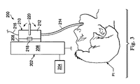
図3及び図4には、患者P1に手術を行う際に使用されるロボット介入システム200が示されている。ロボット介入システム200は、システム100の複数の構成要素のうちのいずれか又は全てを含んでもよいが、明確にするために、選択部品のみが、図3及び図4に示されている。システム200は、遠隔制御装置204(例えば、オペレータ入力システム106)によって制御されるマニピュレータアセンブリ202(例えば、ロボットマニピュレータアセンブリ102)を含む。マニピュレータアセンブリ202は、挿入駆動部206及びピッチ及び/又はヨー駆動部208を含む。これら駆動部206,208は、例えばサーボモータ駆動機構であってもよい。介入器具210は、ハンドピース212、及び患者P1の解剖学的通路内に挿入するためにサイズ決めされた可撓性本体214を含む。光ファイバ216が、可撓性本体の形状を測定するために又は可撓性本体の先端部から画像を記録するために、ハンドピース212及び可撓性本体214を通過する。ラッチ機構218によって、ハンドピース212をマニピュレータアセンブリ202に機械的に結合する。ハンドピース212は、手動アクチュエータ220を含む。
3 and 4 show a
図3の構成では、介入器具210は、ロボット制御モードで使用するためにマニピュレータアセンブリ202に結合される。挿入駆動部206は、遠隔制御装置204でのユーザ入力に応答して、患者P1の内外への可撓性本体214の動きを制御する。駆動部208は、遠隔制御装置204でのユーザ入力に応答して、可撓性本体214の先端部を少なくとも1つの自由度(例えば、ピッチ、ヨー、ロール)の動きで制御する。随意に、駆動部208は、可撓性本体214の先端部を複数の自由度の動きで制御することができる。こうして、このロボット制御構成では、介入器具の挿入及び先端部の運動は、ロボットマニピュレータアセンブリを介して遠隔のユーザによって制御される。
In the configuration of FIG. 3,
図4の構成では、ラッチ機構218の係合を解除するとともに、マニピュレータアセンブリ202の駆動部をハンドピースの駆動入力部(図示せず)から分離することにより、介入器具210をマニピュレータアセンブリ202から切り離す。器具210をアセンブリ202から切り離した状態で、器具210は、ユーザによって直接的に保持され、ユーザは、可撓性本体214を手動で前進又は引き抜いて、器具の挿入を制御する。ユーザは、ハンドピースを回転することによって(例えば、ユーザの手首をねじることによって)、可撓性本体214のロールを制御することができる。可撓性本体214の先端部を1以上の自由度(例えば、ピッチ、又はヨー)の動きで制御するために、ユーザは、手動アクチュエータ220を直接的に切り替える(toggle)。随意に、アクチュエータ220は、可撓性本体214の先端部を複数の自由度の動きで制御する。
In the configuration of FIG. 4, the
図5には、患者P1に手術を行う際に使用するための別のロボット介入システム300が示されている。ロボット介入システム300は、システム100の複数の構成要素のうちのいずれか又は全てを含んでもよいが、明確にするために、選択部品のみが、図5に示されている。システム300は、遠隔制御装置304によって制御されるマニピュレータアセンブリ302を含む。マニピュレータアセンブリ302は、挿入駆動部306を含む。介入器具310が、ハンドピース312、及び患者P1の解剖学的通路に挿入するためにサイズ決めされた可撓性本体314を含む。光ファイバ316が、可撓性本体の形状を測定するために又は可撓性本体の先端部からの画像を記録するために、ハンドピース312及び可撓性本体314を通過する。ハンドピース312は、手動アクチュエータ320を含む。この実施形態では、駆動機構308は、可撓性本体308の先端部を少なくとも1つの自由度の動きで制御するためのサーボモータを含む。駆動機構308及び介入器具310は、マニピュレータアセンブリ302取り付けられており、それによって器具の挿入及び先端部の運動が、図3に示されるように、ロボット制御される。この実施例では、しかしながら、駆動機構308及び器具310をマニピュレータから取り外すことができる。取り外したときに、機構308によって、器具の先端部の動きを継続して制御することができる。電力入力部318によって、駆動機構308を電源に結合することができる。他のケーブル又は無線接続(図示せず)によって、制御指示を遠隔制御装置から駆動機構308に与えることができる。あるいはまた、駆動機構308は、電池又は他の自給式ポータブル電源を含んでおり、器具312の電源ケーブルを用いない使用を可能にする。様々な代替案では、駆動機構308は、依然として器具312に直接的に取り付けられている間に作動停止され、ユーザが、器具の先端部を少なくとも1つの自由度の動きで手動で制御するために、アクチュエータ320を直接的に切り替えることが可能になる。
FIG. 5 shows another
図6には、可撓性本体314に結合されたオプションの挿入駆動部機構322をさらに含むロボット介入システム300が示されている。駆動機構308と同様に、挿入駆動部機構322は、ポータブルとすることができ、別々に駆動及び制御することができる。器具310がマニピュレータ302から取り外されたときに、可撓性本体314を患者P1との間で前進及び引き抜くことを、ポータブルの挿入駆動部機構322によって制御することができる。
FIG. 6 shows a
図7a及び図7bには、本開示の別の実施形態に係る介入器具400が示されている。器具400は、ハンドピース404に結合された細長い可撓性本体402を含む。ハンドピース404は、把持部406、ツールポート408、及びインターフェイスハウジング410を含む。ハンドピースは、ロボットマニピュレータの駆動システムとインターフェイス接続するための複数の駆動入力部412も含む。ハンドピース404は、細長い可撓性本体402の先端部を少なくとも1つの自由度(例えば、ピッチ、ヨー及び/又はロール)の動きで手動で制御するために、ピボット416を中心にして旋回可能な手動アクチュエータ414をさらに含む。この実施形態及び他の実施形態では、少なくとも1つの自由度は、ピッチ運動として参照されるが、ハンドピースの1つ又は複数の手動アクチュエータが、可撓性本体402の先端部をヨー及び/又はロール等の1つ又は複数の他の自由度の動きで制御し得ることを理解されたい。
7a and 7b illustrate an
ツールポート408は、可撓性本体402のチャネルを通じて挿入するための補助ツールを受け取るようにサイズ決めされ且つ及び形状が形成される。補助ツールは、例えばカメラ、生検装置、レーザーアブレーションファイバ、位置及び姿勢センサー、又は他の外科用、診断用、又は治療用ツールを含んでもよい。この実施形態では、把持部406は、人間の手によって快適に把持するようにサイズ決めされたテーパシャフトを有する。様々な代替実施形態では、把持部は、ユーザの指を受けるようにサイズ決めされた凹み(indention)等の人間工学的な特徴、すなわち滑り止め表面を有してもよい。
この実施形態では、ハンドピース404は、細長い突起等の係合機構418を含み、細長い可撓性本体402の挿入方向D2に対して略横断する方向D1に、ハンドピース404をロボットマニピュレータに結合する。この横断方向の結合によって、マニピュレータにハンドピースを結合することによる可撓性本体の先端部が挿入方向D2に移動するリスクが軽減され、こうして患者に損傷を与えるリスクを減らす、又は他には、患者の小さく繊細な解剖学的通路内での可撓性本体の不注意による前進又は後退から生じるナビゲーションが起きないようにする。あるいはまた、細長い可撓性本体502の挿入方向D2に対して略横断する方向D3に、ハンドピース404をロボットマニピュレータに結合する係合機構を設けてもよい。この横断方向の結合によって、ハンドピースをロボットマニピュレータに結合するときに、ハンドピースを方向D2に移動させるようなリスクが減少する。
In this embodiment, the
手動モードでは、ロボットマニピュレータに結合されておらず、ユーザは、器具400の把持部406を把持し、且つユーザの親指が手動アクチュエータ414の近くに又はこれに接して載置されるようにハンドピース404を保持する。ユーザは、患者の解剖学的構造に対してハンドピース404を前進又は引き抜くことによって、挿入の動きを(つまり、方向D2に)手動で制御する。ユーザは、手動アクチュエータ414を運動M2で旋回させることにより、ピッチ運動M1を手動で制御する。例えば、手動アクチュエータを器具の先端部に向けて旋回させることによって、可撓性本体の先端部を上方向にピッチさせ、及び手動アクチュエータを器具の基端部に向けて旋回させることによって、可撓性本体の先端部を下方向にピッチさせる。代替実施形態では、手動アクチュエータの動きによって、反対方向にピッチ運動を生じさせ得る。さらに他の代替案では、手動アクチュエータの動きによって、可撓性本体の先端部を例えばヨー又はロール等の他の自由度の動きとなるようにすることもできる。
In manual mode, the handpiece is not coupled to the robotic manipulator and the user grips the
ロボットモードでは、器具400は、ロボットマニピュレータに直接的に結合される。駆動入力部412は、エンドエフェクタ及び可撓性本体操作機構と、マニピュレータに装着された駆動モータとの機械的な結合を提供する。例えば、駆動入力部のペアによって、可撓性本体の先端部のピッチ運動M1を制御することができ、このペアの1つのアダプタが、上方向の動きを制御し、且つこのペアの他方のアダプタが、反対向きの下方向の動きを制御する。駆動入力部の他のペアは、他の自由度の反対向きの動きを可撓性本体及び/又はエンドエフェクタに与えることができる。ロボットマニピュレータとインターフェイス接続する器具は、1999年10月15日に出願された、”Surgical Robotic Tools, Data Architecture, And Use”を開示する米国特許第6,331,181号、及び2001年1月12日に出願された、”Mechanical Actuator Interface System For Robotic Surgical Tools”を開示する米国特許第6,491,701号に記載されており、これら両文献は、それらの全体を参照することにより本明細書に組み込まれる。
In robot mode,
図8には、本開示の別の実施形態に係る介入器具500が示されている。この器具500は、ハンドピース504に結合された細長い可撓性本体502を含む。ハンドピース504は、把持部506、ツールポート508、及びインターフェイスハウジング510を含む。ハンドピースは、ロボットマニピュレータの駆動システムとインターフェイス接続するための複数の駆動入力部512も含む。
FIG. 8 illustrates an
ハンドピース504は、細長い可撓性本体502の先端部の動きを手動で制御するために、ピボット516を中心にして旋回可能な手動アクチュエータ514をさらに含む。この実施形態では、手動アクチュエータ514は、2つのレバーを含む(図8には明確に示されていないが、図9bの同様の構成を参照)。各レバーは、単一の自由度、例えばピッチ運動の反対向きの運動を制御する。あるいはまた、一方の旋回レバーは、反対向きのヨー運動を制御することができ、他方の旋回レバーは、可撓性本体の先端部の反対向きのピッチ運動を制御することができる。
ツールポート508は、可撓性本体502のチャネルを通じて挿入するための補助ツールを受け取るようにサイズ決めされ且つ形状が形成される。補助ツールは、例えばカメラ、生検装置、レーザーアブレーションファイバ、位置及び姿勢センサー、又は他の外科用、診断用、又は治療用ツールを含んでもよい。この実施形態では、把持部506は、人の手によって快適に把持するようにサイズ決めされたテーパシャフトを有する。様々な代替実施形態では、把持部は、ユーザの指を受けるようにサイズ決めされた凹み(indention)等の人間工学的な特徴、すなわち滑り止め表面を有してもよい。
この実施形態では、細長い突起部518等の係合機構によって、細長い可撓性本体502の挿入方向D2に対して略横断する方向D1に、ハンドピース504をロボットマニピュレータに結合することが可能になる。この横断方向の結合によって、ハンドピースをマニピュレータに結合することによる可撓性本体の先端部を挿入方向D2に移動させるリスクが軽減され、こうして、患者に損傷を与えるリスクを減らす、又は他には、患者の小さく繊細な解剖学的通路内での可撓性本体の不注意による前進又は後退から生じるナビゲーションが起きないようにする。
In this embodiment, an engagement mechanism such as an
ハンドピース504は、ロボットマニピュレータから器具500を取り外すためのラッチ解除機構をさらに含む。この実施形態では、ラッチ解除機構は、付勢部材(例えば、引張ばね)によって接続され且つリンク機構のペア522に接続されたタブのペア520を含む。ハンドピース504をロボットマニピュレータに結合した場合に、タブ520を一緒に握ることによって、リンク機構をロボットマニピュレータに向けて移動させ、ロボットマニピュレータからハンドピース入力部512の係合を解除する。次に、ハンドピース504は、ロボットマニピュレータから係合が解除され、解除後に、器具500を手動モードで操作することができる。手動及びロボット制御モードでの器具500の作動は、デュアルレバー手動アクチュエータ514によって、ユーザが手動モードで、可撓性本体の先端部の単一の自由度の反対向きの動き(例えば、上方向ピッチ及び下方向ピッチ)を制御することが可能になることを除いて、器具400について上述した作動と同様である。あるいはまた、デュアルレバー手動アクチュエータは、2つのレバーのそれぞれが、2つの方向で異なる自由度で制御する(例えば、右レバーが上下方向ピッチを制御し及び左レバーが左右方向ヨーを制御する)ように構成することができる。
図1に示されるように、手動アクチュエータ24はユーザによって操作され、ハンドピース14が手動モードで使用される場合に、可撓性本体の先端部の動きを制御する。図9a、図10、図11aには、手動アクチュエータの別の実施形態が示されている。他の点では、図9a、図10a、及び図11は、図1と同様である。
As shown in FIG. 1, the
図9aには、介入器具600が概略的に示されており、図9b、図9c、図9d、図9e、図9f、及び図9gには、図9aに概略的に示される介入器具600の実装態様が示されている。システム600は、把持部603を含むハンドピース器具604に結合されたカテーテルシステム602を含む。カテーテルシステム602は、細長い可撓性本体606を含む。可撓性本体606は、可撓性本体の先端部を1つの自由度(例えば、ピッチ運動の自由度)で反対向きの方向に移動させるための対向駆動部品608a,608bを収容する。可撓性本体606は、可撓性本体の先端部を別の自由度(例えば、ヨー自由度)で反対方向に移動させるための対向駆動部品610a,610bも収容する。この実施形態では、駆動部品は、ハンドピース器具604から可撓性本体の先端部に延びる引張ワイヤ等の腱である。
9a schematically illustrates an
ハンドピース器具604は、フレーム611、及びこのフレームに回転可能に結合されたプーリー612a,612b,613a,614a,614b,615a,615bを含む。アライメント機構617a,617bもフレーム611に結合される。ハンドピース604は、巻上げ機構618に機械的にリンク結合されたレバー616aを含むような手動アクチュエータ619をさらに含む。手動アクチュエータ619は、巻上げ機構620に機械的にリンク結合されたレバー616bも含む。ばね等の付勢部材625が、巻上げ機構618,620の間に延びる。
The
ハンドピース器具604は、電動駆動システム624によって可動する駆動入力部622aをさらに含み、駆動部品608aの動きをある自由度の一方向(例えば、下方向ピッチ)に制御する。ハンドピース604は、電動駆動システム628によって可動する駆動入力部626aも含み、駆動部品608bの動きを同じ自由度の反対方向(例えば、上方向ピッチ)に制御する。駆動システム624,628は、駆動モータを含むロボットマニピュレータの構成要素である。駆動入力部622aは、ディスク形状の係合部622b及び入力シャフト部622cを含む。螺旋溝巻上げ駆動部622dが、シャフト部622cによって支持される。係合部622bは、駆動システム624に取り外し可能に結合することができる。入力シャフト部622cは、係合部622bに一体的に形成される又は固定的に結合される。駆動入力部626aは、係合部622b及び入力シャフト部626cを含む。螺旋溝巻上げ駆動部626dは、シャフト部626cによって支持される。係合部626bは、駆動システム628に取り外し可能に結合することができる。入力シャフト部626cは、係合部626bに一体的に形成される又は固定的に結合される。ハンドピース器具604は、対向駆動部品608a,608bによってたるみが生じるのを防止するとともに、これら対向駆動部品が、駆動入力巻上げ機、プーリー、又はレバー巻上げ機構から分離される又はこれらと絡まることを防止するような張力調整システム632(例えば、ピッチ方向張力調整システム)をさらに含む。
The
ハンドピース器具604は、電動駆動システム637によって可動する駆動入力部636aをさらに含み、駆動部品610aの動きをある自由度の一方向(例えば、右方向ヨー)に制御する。螺旋溝巻上げ駆動部636bが、駆動入力部636aに結合される。ハンドピース604は、電動駆動システム639によって可動する駆動入力部638aを含み、駆動部品610bの動きを同じ自由度の反対方向(例えば、左方向ヨー)に制御する。螺旋溝巻上げ駆動部638bが、駆動入力部638aに接続される。これら駆動システム637,639は、駆動モータを含むロボットマニピュレータの構成要素である。ハンドピース器具604は、対向駆動部品610a,610bによってたるみが生じるのを防止するとともに、これら対向駆動部品が、駆動入力巻上げ機又はプーリーから分離されることを防止するような張力調整システム634(例えば、ヨー方向張力調整システム)をさらに含む。システム632,634等のギヤベースの張力調整システムの動作は、図12a,12bでより詳細に説明する。
The
この実施形態では、駆動部品608a,608b,610a,610bのそれぞれは、ハンドピース器具604の先端部を通じて可撓性本体606内に延びる引張ワイヤ部分を含む。このワイヤ部分は、例えば圧着(crimping)によって、駆動入力部とワイヤ部分との間に延びるケーブル部分に結合される。ケーブル部分は、ねじれ(kink)に抗することができ、駆動部品が、ハンドピースのプーリーシステムにおいて緊密な旋回でトラバースすることが可能になる。代替実施形態では、駆動部品は、連続した長さの腱から形成することができる。
In this embodiment, each of the
下方向ピッチの駆動部品608aのケーブル部分は、巻上げ駆動部622dの周囲に及びアライメント機構617aの一部の上に巻き付けられており、駆動部品をプーリー612aと位置合わせする。この実施形態では、駆動部品608aは、プーリー612aを中心にして約90度〜135°の間の角度で曲げられる。代替実施形態では、プーリーによって形成されたケーブルの角度は、これよりも大きくても小さくてもよい。駆動部品608aが、レバー巻上げ機構618の周囲に延びており且つこの機構に固定される。駆動部品の別の長さのケーブルは、レバーの巻上げ機構618に固定され、且つプーリー612b上に延びており、駆動部品608aの引張ワイヤ部分に圧着(crimp)される。代替実施形態では、ケーブル部分は、巻上げ機618に固定された別個の部分のない連続体であってもよい。
The cable portion of the downward
上方向ピッチの駆動部品608bのケーブル部分は、巻上げ駆動部626bの周囲に及びアライメント機構617bの一部の上に巻き付けられており、駆動部品をプーリー613aと位置合わせする。この実施形態では、駆動部品608bは、プーリー613aを中心にして約90°の角度で曲げられる。駆動部品は、レバー巻上げ機構620の周囲に延びており、且つこの機構に固定される。駆動部品の別の長さのケーブルは、レバーの巻上げ機構620に固定され、且つ駆動部品608bの引張ワイヤ部分に圧着される。代替実施形態では、ケーブル部分は、巻上げ機620に固定された別個の部分のない連続体であってもよい。
The cable portion of the upward
右方向ヨーの駆動部品610aのケーブル部分は、巻上げ駆動部636bの周囲に巻き付けられており、且つプーリー607aの上及びプーリー614bの周囲に少なくとも部分的に延びており、駆動部品610aの引張ワイヤ部分に圧着される。左方向ヨーの駆動部品610bのケーブル部分は、巻上げ駆動部638bの周囲に、プーリー615aの周囲に少なくとも部分的に、プーリー607bの周囲に少なくとも部分的に、及びプーリー615bの周囲に少なくとも部分的に巻き付けられる。次に、ケーブル部分は、駆動部品610bの引張ワイヤ部分に圧着される。様々な巻上げ機、アライメント機構、及びプーリーは、ケーブルが駆動入力部とカテーテルシステムとの間でハンドピースをトラバースする際に、絡まりのない、整列した、及びキンクのないケーブルを維持するのに役立つ。駆動入力シャフトの軸線(例えば、シャフト622cの軸線A1)は、把持部603の軸線A2と略垂直であるので、駆動部品は、ハンドピース604内でのそれら経路に沿って略直角に少なくとも一度曲げることができる。
The cable portion of the right-hand
手動モードでの使用中に、臨床医は、ハンドピース604の把持部603をレバー616a及び616bの近くに位置付けされた親指で把持する。手動モードでは、臨床医は、カテーテル602の先端部605の動作範囲(例えば、ピッチ、ロール、及び挿入)を制御することができる。カテーテルの先端部605を下方向ピッチ(下方向D1)で動かすには、臨床医は、回転運動をレバー巻上げ機618に伝達するようなレバー616aを(例えば、図9bにおいて時計回りに)押す。レバー巻上げ機618の回転によって、駆動部品608aが後退し、カテーテル602の先端部605を下方向にピッチさせる。レバー616aは、臨床医が各レバーに関連する動きの方向を容易に認識することができるように、異なる傾斜面又は他の触覚刺激(cue)を含んでもよい。カテーテルの先端部605を上方向ピッチ(上方向D1)で動かすには、臨床医は、回転運動をレバー巻上げ機620に伝達するようなレバー616bを(例えば、図9eの時計回りに)押す。レバー巻上げ機620の回転によって、駆動部品608bが後退し、カテーテル602の先端部605を上方向にピッチにさせる。軸線A2を中心にしたカテーテル602の先端部605の回転は、臨床医の手首の曲げによって制御される。カテーテル602の先端部605の挿入は、臨床医が、患者に対してハンドピース604を前進又は後退させることにより制御される。
During use in manual mode, the clinician grips
器具システム600をロボット制御モードに移すには、駆動入力部622a,626a,636a,638aを、ロボットマニピュレータの電動駆動システム624,628,637,639にそれぞれ結合する。前述したように、駆動入力及び駆動システムの結合は、挿入軸線A2に対して横断方向に生じ、カテーテル602の先端部605を前進又は後退させるようなリスクを低減する。
To move the
ロボット制御モードでは、臨床医は、カテーテル602の先端部605の運動範囲(例えば、ピッチ、ヨー、ロール、及び挿入)を制御することができる。駆動入力部622aの動作によって、巻上げ機622dを回転させ且つ駆動部品608aを後退させ、カテーテル602の先端部605を下方向にピッチにさせる。駆動入力部626aの動作によって、巻上げ機626bを回転させ且つ駆動部品608bを後退させ、カテーテル602の先端部605を上方向にピッチにさせる。駆動入力部636aの動作によって、巻上げ機636bを回転させ且つ駆動部品610aを後退させ、カテーテル602の先端部605を右方向にヨーにさせる。駆動入力部638aの動作によって、巻上げ機638bを回転させ且つ駆動部品610bを後退させ、カテーテル602の先端部605を左方向にヨーにさせる。カテーテル602の先端部605の回転及び挿入は、ロボットマニピュレータの動作によって制御される。
In the robot control mode, the clinician can control the range of motion (eg, pitch, yaw, roll, and insertion) of the
ハンドピースをロボットマニピュレータから取り外し且つハンドピース604を手動モードに移行するには、ラッチ解除機構630のタブ630aを握り、ばね631を圧縮する(図9cを参照)。タブを一緒に握ることによって、リンク機構630bをロボットマニピュレータに向けて移動させ、随意に図1の27及び29等のアダプタを担持するプレートを移動させ、駆動システムから駆動入力部の係合を解除し、本体606の軸線A2に対して横断する方向にロボットマニピュレータからハンドピース604の係合を解除することを可能にする。
To remove the handpiece from the robot manipulator and move the
図9bに示されるようには、ハンドピース604は、可撓性本体606のチャネルを通じて挿入するための補助ツールを受け取るようにサイズ決めされ且つ成形されたツールポート640も含む。ツールポートの位置は、駆動部品及び臨床医の把持部に適合するように決定することができる。図9gを参照すると、ハンドピース604は、可撓性本体616を把持部603に結合するカラー641も含む。駆動部品608a,608b,610a,610bの少なくとも一部は、コイル状の細長い外側シースに対して可動する細長い内側部品(例えば、ワイヤ又はケーブル)を有するようなボーデンケーブル643から形成してもよい。前述したように、内側部品を駆動部品のケーブル部分に圧着してもよい。スタッド部品642が、(例えば、エポキシによって)コイル状外側シースに取り付けられ、且つ留め具645によって所定の位置に保持されるクランププレート644によって、把持部603に対して固定保持される。駆動部品が手動又はロボット制御のいずれかで操作される際に、駆動部品のボーデンケーブル部分は、ハンドピース604のスロット646(図9b)を介して屈曲され且つ突出させることができる。これは、コイル状外側シースが基端部で拘束されるので、クランププレートは、軸線A2に沿った軸線方向の移動が制約される。
As shown in FIG. 9 b,
図10には、介入器具650が概略的に示されている。この実施形態では、介入器具は、単一の制御レバーを含む手動アクチュエータ、及び対向駆動部品同士の間に結合された張力調整システムを有する。システム650は、器具のハンドピース654に結合されたカテーテルシステム652を含む。カテーテルシステム652は、細長い可撓性本体656を含む。可撓性本体656は、可撓性本体の先端部を1つの自由度(例えば、ピッチ自由度の運動)で反対方向に移動させるための対向駆動部品658a,658bを収容する。
In FIG. 10, an
ハンドピース器具654は、図9aに開示された手動アクチュエータ619のレバー巻上げシステム616b/620,616a/618のいずれかと同様の手動操作レバー巻上げシステム660を含む。レバー巻上げシステム660は、ユーザによる手動操作のための単一のレバー662に結合される。レバー662及びレバー巻上げシステム660が一緒になって、手動アクチュエータを形成する。ハンドピース器具654は、駆動システム666によって可動する駆動入力部664を含み、駆動部品658aの動きを制御する。ハンドピース器具654は、駆動システム670によって可動する駆動入力部668も含み、対向駆動部品658bの動きを制御する。駆動システム666,670は、駆動モータを含むロボットマニピュレータの構成要素である。ハンドピース器具654は、対向駆動部品658a,658bによってたるみが生じるのを防止するとともに、これら対向駆動部品が、駆動入力部又はケーブルホイールシステムから分離される又はこれらの周囲に絡まることを防止するような張力調整システム672をさらに含む。
The
手動モードでの使用中に、臨床医は、単一のレバー662を操作して、単一の自由度について反対向きの両方の動きを制御する。例えば、レバーを前進させることによって、可撓性本体の先端部を上方向ピッチで動かすことができ、レバーを後退させることによって、可撓性本体の先端部を下方向ピッチで動かすことができる。ロボット制御モードでは、器具システム650は、器具システム600について説明したのと同様の方法で制御するためにロボットマニピュレータに結合される。この実施形態では、ロボットマニピュレータの駆動システムは、単一の自由度について反対向きの動きのみ、例えば上下方向ピッチのみを制御する。代替実施形態では、器具システム600について説明したのと同様の第2の駆動入力部のセット及び張力調整システムを使用して、第2の自由度についての反対向きの運動、例えば左右方向ヨー運動をロボット制御することができる。
During use in manual mode, the clinician operates a
図11aには、介入器具675における第2の自由度の駆動入力部のセット及び張力調整システム等が概略的に示されており、図11Bには、図11aに概略的に示された介入器具の実装形態が示されている。システム675は、ハンドピース器具679に結合されたカテーテルシステム677を含む。カテーテルシステム12は、細長い可撓性本体681を含む。可撓性本体681は、可撓性本体の先端部を単一の自由度(例えば、ピッチ)で反対方向に移動させるための対向駆動部品683a,683bを収容する。可撓性本体681は、可撓性本体の先端部を別の単一の自由度(例えば、ヨー)で反対方向に移動させるための対向駆動部品685a,685bを収容する。ハンドピース679は、ハンドピース600について説明したのと同様の駆動入力部及びピッチ方向張力調整システムを含むようなピッチ制御システム684を含む。ハンドピース679は、ハンドピース600について説明したのと同様の駆動入力部及びヨー方向張力調整システムを含むようなヨー制御システム686を含む。この実施形態では、手動アクチュエータ688は、ギヤラック695に機械的に係合する、ピニオンギヤ693に機械的にリンク接続された単一のレバー691を含む。ピッチ対向駆動部品683a,683bは、ギヤラック695に結合される。
FIG. 11a schematically illustrates a set of second degree of freedom drive inputs and a tension adjustment system, etc., in the
ロボット制御モードでは、器具システム675を、器具システム600について説明したように実質的に作動させることができる。手動制御モードでは、臨床医は、例えば親指でレバー691を操作して、ピッチ対向駆動部品683a,683bを移動させる。この実施形態では、ハンドピース679の先端部に向けてレバー691を旋回することにより、ギヤ693を回転させ、ラック及びピニオンアームを反対方向に移動させ、こうして駆動部品683bを後退させ、駆動部品683aを前進させる。ハンドピース679の基端部に向けてレバー691を旋回したときに、ギヤ693が回転し、ラック及びピニオンアームを反対方向に移動させ、こうして駆動部品683aを後退させ、駆動部品683bを前進させる。
In the robot control mode, the
様々な実施形態では、ハンドピース内の駆動入力部をロボット介在システムの電動駆動システムに結合してもよく、それによって、ロボット制御モードでは、駆動入力部は、複数の自由度(例えば、ピッチ及びヨー)を制御する一方、手動モードでは、より少ない自由度(例えば、ピッチのみ)を手動アクチュエータによって制御してもよい。あるいはまた、同数の自由度を手動及びロボット制御の両方で制御してもよい。 In various embodiments, the drive input in the handpiece may be coupled to the electric drive system of the robotic intervention system, so that in robot control mode, the drive input has multiple degrees of freedom (e.g., pitch and In the manual mode, a smaller degree of freedom (for example, only the pitch) may be controlled by a manual actuator. Alternatively, the same number of degrees of freedom may be controlled by both manual and robotic control.
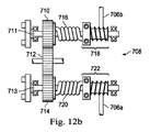
図12aには、介入器具700が概略的に示されている。この器具700は、ハンドピース器具704に結合されたカテーテルシステム702を含む。カテーテルシステム702は、可撓性本体の先端部を1つの自由度(例えば、ピッチ自由度の運動)で反対方向に移動させるための対向駆動部品706a,706bを収容する。器具700は、対向駆動部品706a,706bによってたるみが生じるのを防止するとともに、これら対向駆動部品が、駆動入力部又は手動アクチュエータから分離される又はこれらと絡まることを防止するようなギヤ及びばね張力調整システム708を有する。同様の張力調整システム632,634は、器具システム600で使用されている。
In FIG. 12a, an
図12bには、アイドルギヤ712によってギヤ714に結合されたギヤ710を含むような張力調整システム708の一部が示されている。張力調整システム708は、前述した器具システムのいずれかに張力調整システムとして適用することができる。ギヤ710は、ハンドピース704に回転可能に取り付けられたシャフト711に回転可能に結合される。例えば捩じりばね等の付勢部材716は、ギヤ710に対して一端が結合され、シャフト711に固定された巻上げ機718に対して他端が結合される。駆動部品706bが、巻上げ機718の周囲に巻き付けられる。同様に、ギヤ714は、ハンドピース704に回転可能に取り付けられたシャフト713に回転可能に結合される。捩じりばね等の付勢部材720は、ギヤ714に対して一端が結合され、シャフト713に固定された巻上げ機722に対して別の端部が結合される。駆動部品706aが、巻上げ機722の周囲に巻き付けられる。
FIG. 12 b shows a portion of a
従って、巻上げ機718は、ギヤ710,712,714及びばね716,720を介して巻上げ機722に従動するように結合される。また、駆動部品706bは、張力調整システム708を介して駆動部品706aに従動するように結合される。ギヤ及びばね張力調整システム708が、ばね716,720にねじり前負荷を受けた状態で組み立てられ、且つ張力を駆動部品706a,706bに付与するときに、ばねは、例えば駆動システムが分離され、トルクが駆動入力部に適用されない場合に、駆動部品同士の間で発生し得るたるみを補償することができる。708等の張力調整システムは、駆動部品の不均一な運動が、駆動部品608a,608b又はカテーテル602における摩擦及び軸線方向のコンプライアンスに起因して又はカテーテル602の屈曲に起因して発生したときに、駆動部品同士(例えば、ハンドピース604の駆動部品608a,608b)の間の張力を維持することができる。
Accordingly, the
使用中に、例えば下方向ピッチ駆動部品706aが、(手動又はロボット制御のいずれかを介して)後退するときに、対向駆動部品706bは、巻上げ機718の回転に伴って、少なくとも部分的に展開(unfurl)される。ばね716を介して、巻上げ機718に関する少なくとも一部のトルクがギヤ710に伝達される。ギヤ714に関するトルクによって、同じ方向にギヤ710にトルクが適用される。ギヤ714に関するトルクが、ばね720を介して巻上げ機722に少なくとも部分的に付与され、対向駆動部品706aに表れるたるみを防止する。こうして、対向駆動部品706a,706bは、所定の張力状態に維持される。対向駆動部品の不均一な動きが生じる状態での張力調整システム708のこの使用は、駆動部品608a,608bの不均一な動きによって、手動アクチュエータ619の分割レバー巻上げ機において、入力部でのケーブルたるみに影響を与えるので、器具システム600において特に適用可能にすることができる。
In use, for example when the downward
図13aには、介入器具750が概略的に示されている。この器具750は、ハンドピース器具754に結合されたカテーテルシステム752を含む。カテーテルシステム752は、可撓性本体の先端部を1つの自由度(例えば、ピッチ自由度の運動)で反対方向に移動させるための対向駆動部品756a,756bを収容する。器具750は、対向駆動部品756a,756bによってたるみが生じるのを防止するとともに、これら対向駆動部品が、駆動入力部又は手動アクチュエータから分離されることを防止するようなケーブル張力調整システム758を有する。
In FIG. 13a, an
図13bには、巻上げ機に固定されるとともにこの巻き上げ機の周囲に少なくとも部分的に巻き付けられたケーブル774によって、巻上げ機768に結合された巻上げ機766を含むような張力調整システム758の一部が示されている。巻上げ機766は、ハンドピース754に回転可能に取り付けられたシャフト770に回転可能に結合される。捩じりばね等の付勢部材762は、シャフト770によって支持されており、巻上げ機766に対して一端が結合され、且つ巻上げ機760に対して他端が結合される。駆動部品756bは、巻上げ機760の周囲に巻き付けられる。同様に、巻上げ機768は、ハンドピース754に回転可能に取り付けられたシャフト772に回転可能に結合される。捩じりばね等の付勢部材764は、巻上げ機768に対して一端が結合され、且つ巻上げ機762に対して別の端部が結合される。駆動部品756aが、巻上げ機762の周囲に巻き付けられる。
FIG. 13 b shows a portion of a
捩じりばね762,764の前負荷が与えられた巻き上げによって、トルクやロックが駆動入力部に適用されていない場合や駆動部品の不均一な動きによって他の方法でたるみを形成する場合に、駆動部品756a,756bにおける張力を維持する。使用中に、例えば、下方向ピッチ駆動部品756aが、(手動又はロボット制御のいずれかを介して)後退する場合に、対向駆動部品756bは、巻上げ機756の回転に伴って、少なくとも部分的に展開される。ばね762を介して、巻上げ機760に関する少なくとも一部のトルクが、巻上げ機766に伝達される。巻上げ機766に関するトルクが、ケーブル774を介して少なくとも部分的に付与され、巻上げ機768にトルクを適用する。巻上げ機768に関するトルクが、ばね764を介して少なくとも部分的に付与され、トルクを巻上げ機762に適用して、対向駆動部品756aにたるみが形成されるのを防止する。こうして、対向駆動部品756a,756bは、所定の張力状態に維持される。
When the preload of the torsion springs 762 and 764 is applied, when torque or lock is not applied to the drive input unit or when slack is formed by other methods due to uneven movement of the drive parts, The tension in the driving
図14aには、介入器具800が概略的に示されている。器具800は、ハンドピース器具804に結合された可撓性本体802を含む。可撓性本体802は、可撓性本体の先端部を1つの自由度(例えば、ピッチ自由度の運動)で反対方向に移動させるための対向駆動部品806a,806bを収容する。器具800は、対向駆動部品806a,806bによってたるみが生じるのを防止するとともに、これら対向駆動部品が、駆動入力部又は手動アクチュエータから分離される又はこれらに絡まることを防止するようなプーリー及びばね張力調整システム808を有する。
In FIG. 14a, an
図14bには、ハンドピース804に固定されたプーリー810含むような張力調整システム808の一部が示されている。引張ばね等の付勢部材812が、駆動部品806a,806bの間に取り付けられる。駆動部品806a,806bの少なくとも一方が、プーリー810と交差して延びる。使用中に、ばね812は、駆動部品806a,806bの動きが等しくない場合に、又はトルクが入力部に適用されない場合に、両方の駆動部品の少なくとも一部の張力が維持されるように前負荷される。これによって、駆動部品が張力調整システムのプーリーや巻上げ機又は駆動入力部や手動アクチュエータから係合が解除されない又はこれらに絡まないことが保証される。
FIG. 14 b shows a portion of a
使用中に、例えば下方向ピッチ駆動部品756aが、(手動又はロボット制御のいずれかを介して)後退する場合に、対向駆動部品756bは、巻上げ機756の回転に伴って少なくとも部分的に展開される。ばね762を介して、少なくとも一部のトルクが、巻上げ機760に適用され、巻上げ機766に伝達される。巻上げ機766の動きが、ケーブル774を介して少なくとも部分的に付与され、巻上げ機768を回転させる。巻上げ機768の回転が、ばね764を介して少なくとも部分的に付与され、巻上げ機762を回転させ、対向駆動部品756aに形成されたたるみを取る。こうして、対向駆動部品756a,756bは、所定の張力状態に維持される。
In use, for example when the downward
図15には、本開示の実施形態に係る介入器具の使用方法が示されている。上術した実施形態のいずれかの介入器具が、852で提供される。介入器具が駆動機構から取り外された状態の860において、手動モードで器具を操作することができる。 FIG. 15 illustrates a method for using an interventional device according to an embodiment of the present disclosure. The interventional instrument of any of the above-described embodiments is provided at 852. At 860 with the interventional instrument removed from the drive mechanism, the instrument can be operated in manual mode.
手動モードでは、介入器具の手動アクチュエータは、ユーザからの力(例えば、親指レバーに接するユーザの親指の圧力)を受け取り、細長い可撓性器具の先端部を移動させる。第1の方向に移動した(例えば、親指レバーをハンドピースの先端部に向けて切り替えた)場合に、手動アクチュエータによって第1の駆動部品を移動させて、細長い可撓性シャフの先端部の第1の方向(例えば、上向きピッチ方向)の動きを制御する。第2の方向に移動した(例えば、親指レバーをハンドピースの基端部に向けて切り替えた)場合に、手動アクチュエータによって第2の駆動部品を移動させ、細長い可撓性シャフトの先端部の、第1の方向とは反対側の第2の方向(例えば、下向きピッチ方向)の動きを制御する。 In manual mode, the manual actuator of the interventional instrument receives a force from the user (eg, the pressure of the user's thumb against the thumb lever) and moves the tip of the elongated flexible instrument. When moved in the first direction (for example, when the thumb lever is switched toward the tip of the handpiece), the first drive component is moved by the manual actuator to change the first of the tip of the elongated flexible shuff. The movement in one direction (for example, upward pitch direction) is controlled. When moved in the second direction (e.g., the thumb lever is switched toward the proximal end of the handpiece), the second drive component is moved by a manual actuator to the distal end of the elongated flexible shaft, The movement in the second direction (for example, the downward pitch direction) opposite to the first direction is controlled.
856で、介入器具は、ロボット手術システムに結合される。具体的には、ロボット手術システムの電動駆動機構が、介入器具のモーターインターフェイスを受け取る。随意に、介入器具のモーターインターフェイスは、駆動機構において、介入器具の細長いシャフトの長手方向軸線に対して略横断する方向に受容され、患者内に挿入されるその軸線に沿った器具の動きを最小化又は排除する。858で、電動機構の駆動入力部を作動して、細長い可撓性シャフトの先端部を第1の自由度(例えば、ピッチ)で移動させる。ロボット制御モードでは、介入器具の駆動入力部の一方のペアが、電動駆動システムから力を受け取り、細長い可撓性器具の先端部を移動させる。作動された場合に、駆動入力部の一方のペアは、第1の駆動部品を移動させて、細長い可撓性シャフトの先端部の第1の方向(例えば、上向きピッチ方向)の動きを制御する。作動された場合に、駆動入力部の他方のペアが、第2の駆動部品を移動させて、細長い可撓性シャフトの先端部の、第1の方向とは反対向きの第2の方向(例えば、下向きピッチ方向)の動きを制御する。 At 856, the interventional instrument is coupled to the robotic surgical system. Specifically, the electric drive mechanism of the robotic surgical system receives the motor interface of the interventional instrument. Optionally, the motor interface of the interventional instrument is received in the drive mechanism in a direction generally transverse to the longitudinal axis of the interventional instrument's elongate shaft to minimize movement of the instrument along that axis inserted into the patient. Or eliminate. At 858, the drive input of the electric mechanism is actuated to move the distal end of the elongated flexible shaft with a first degree of freedom (eg, pitch). In the robotic control mode, one pair of interventional instrument drive inputs receives force from the electrically driven drive system and moves the distal end of the elongated flexible instrument. When actuated, one pair of drive inputs moves the first drive component to control the movement of the distal end of the elongate flexible shaft in a first direction (eg, upward pitch direction). . When actuated, the other pair of drive inputs moves the second drive component to a second direction of the elongate flexible shaft tip opposite the first direction (e.g., , Movement in the downward pitch direction).
860で、介入器具のモーターインターフェイスは、駆動機構から分離される。随意に、介入器具のモーターインターフェイスは、細長いシャフトの長手方向軸線に対して横断する方向に分離される。シャフトを横断する方向に駆動機構から器具を結合する及び分離することによって、器具がロボット制御モードと手動制御モードとの間で移動する際に、介入器具の先端部の挿入深さを変化させるようなリスクを減少させる。 At 860, the interventional instrument motor interface is decoupled from the drive mechanism. Optionally, the motor interface of the interventional instrument is separated in a direction transverse to the longitudinal axis of the elongate shaft. By coupling and separating the instrument from the drive mechanism in a direction transverse to the shaft, the insertion depth of the interventional instrument tip is changed as the instrument moves between the robot control mode and the manual control mode. Reduce risk.
本開示のシステム及び方法は、肺の接続された気管支の通路に使用するために説明してきたが、それらシステム及び方法は、結腸、腸、腎臓、脳、心臓、循環器系等を含む様々な解剖学的システムにおいて、自然に又は外科的に形成された接続通路を介した、他の組織のナビゲーションや処置に適している。本開示の方法及び実施形態は、非介入的用途にも適している。 Although the systems and methods of the present disclosure have been described for use in the connected bronchial passages of the lung, the systems and methods are various, including the colon, intestine, kidney, brain, heart, circulatory system, etc. In anatomical systems, it is suitable for navigation and treatment of other tissues via naturally or surgically formed connection passages. The methods and embodiments of the present disclosure are also suitable for non-interventional applications.
本発明の実施形態の1つ又は複数の要素は、制御システム116等のコンピュータシステムのプロセッサ上で実行されるソフトウェアで実装してもよい。ソフトウェアで実装された場合に、本発明の実施形態の要素は、基本的に、必要なタスクを実行するためのコードセグメントである。プログラム又はコードセグメントは、プロセッサ可読記憶媒体、又は伝送媒体又は通信リンクを通じた搬送波で具現化されるコンピュータデータ信号を介してダウンロードしてもよいデバイスに格納することができる。プロセッサ可読記憶装置は、光媒体、半導体媒体、及び磁気媒体を含む、情報を格納することができる任意の媒体含むことができる。プロセッサ可読記憶装置の例は、半導体装置、半導体記憶装置、読取り専用メモリ(ROM)、フラッシュメモリ、消去可能なプログラマブル読取り専用メモリ(EPROM)、フロッピーディスク、CD−ROM、光ディスク、ハードディスク、又は他の記憶装置等の電子回路を含む。コードセグメントは、インターネット、イントラネット等のコンピュータネットワークを介してダウンロードしてもよい。
One or more elements of an embodiment of the invention may be implemented in software running on a processor of a computer system such as
提示されるプロセス及び表示は、任意の特定のコンピュータ又は他の装置に本質的に関連しなくてもよいことに注意されたい。様々なこれらのシステムに必要な構成は、特許請求の範囲において要素として表される。また、本発明の実施形態は、特定のプログラミング言語を参照して記載されるわけではない。本明細書に説明されているように、様々なプログラミング言語が、本発明の教示を実施するために使用することができることを理解されるであろう。 Note that the processes and displays presented may not be inherently related to any particular computer or other device. The required structure for a variety of these systems will appear as elements in the claims. In addition, embodiments of the present invention are not described with reference to any particular programming language. It will be appreciated that a variety of programming languages can be used to implement the teachings of the invention, as described herein.
本発明の特定の例示的な実施形態について説明し且つ添付の図面に示してきたが、このような実施形態は、単なる例示であり、広範な本発明に対する制限ではなく、本発明の実施形態は、様々な他の修正が当業者に想起されるので、図示され及び説明された特定の構成及び配置に限定されるものではないことを理解すべきである。 Although specific exemplary embodiments of the present invention have been described and illustrated in the accompanying drawings, such embodiments are merely exemplary and are not a limitation on the broad invention, and embodiments of the invention It should be understood that various other modifications will occur to those skilled in the art and are not limited to the specific configuration and arrangement shown and described.
Claims (15)
医療器具の基端部に結合するように構成されたハンドピース本体と;
前記ハンドピース本体に装着された手動アクチュエータと;
前記ハンドピース本体に取り付けられるとともに、電動駆動機構に取り外し可能に係合するように構成された複数の駆動入力部と;
前記手動アクチュエータに操作可能に結合されるとともに、前記複数の駆動入力部のうちの1つの入力部に操作可能に結合され、前記医療器具の先端部の動きを第1の方向に制御するための第1の駆動部品と;
前記手動アクチュエータに操作可能に結合されるとともに、前記複数の駆動入力部のうちの別の入力部に操作可能に結合され、前記医療器具の先端部の動きを第2の方向に制御するための第2の駆動部品と;を有し、
第1及び第2の駆動部品は、前記医療器具の前記先端部から前記手動アクチュエータを介して前記複数の駆動入力部のそれぞれの駆動入力部まで延びる、
システム。 A system, which is:
A handpiece body configured to couple to a proximal end of a medical device;
A manual actuator mounted on the handpiece body;
A plurality of drive input portions attached to the handpiece body and configured to removably engage an electric drive mechanism;
Operatively coupled to the manual actuator and operably coupled to one of the plurality of drive inputs to control movement of the distal end of the medical instrument in a first direction A first drive component;
Operatively coupled to the manual actuator and operably coupled to another input of the plurality of drive inputs to control movement of the distal end of the medical instrument in a second direction A second drive component;
First and second drive parts, extends from the distal end portion of the front Symbol medical instrument to the respective driving input portion of the plurality of drive input part via said manual actuator,
system.
請求項1に記載のシステム。 The manual actuator includes a first lever and a second lever, and the first drive component is operably coupled to the first lever and one of the plurality of drive input units, The movement of the tip is controlled in the first direction, and the second drive component is operably coupled to the second lever and one of the plurality of drive inputs, and the tip of the medical instrument Control the movement of the camera in the second direction,
The system of claim 1.
請求項1に記載のシステム。 A tension adjustment system coupled to the handpiece body and adapted to maintain tension in the first and second drive components;
The system of claim 1.
請求項3に記載のシステム。 The tension adjustment system includes a pulley system coupled to first and second drive components, a gear mechanism that interconnects a pair of input portions of the plurality of drive input portions, or the plurality of drive input portions. Including cables that interconnect the inputs of a pair of
The system according to claim 3.
請求項3に記載のシステム。 At least one input of the plurality of drive inputs includes a winder coupled to a first drive component, and the tension adjustment system includes a spring coupled to the winder;
The system according to claim 3.
請求項3に記載のシステム。 The plurality of drive input units include a pair of opposed drive input units, each input unit of the opposed drive input unit includes a winder, and the pair of opposed drive input units is formed by a spring. Connected,
The system according to claim 3.
前記ハンドピース本体内に収容されるとともに、第1及び第2の駆動部品に結合されたラック及びピニオン機構及び該ラック及びピニオン機構に結合された旋回レバー、或いは
前記ハンドピース本体内に収容されるとともに、少なくとも第1の駆動部品に結合される巻上げ機及び前記巻上げ機に固定して結合された旋回レバー
を含む、
請求項1に記載のシステム。 The manual actuator is:
A rack and pinion mechanism coupled to the first and second drive components and a swivel lever coupled to the rack and pinion mechanism, or accommodated in the handpiece body. And a hoisting machine coupled to at least the first drive component and a turning lever fixedly coupled to the hoisting machine,
The system of claim 1.
請求項1に記載のシステム。 The second direction is opposite to the first direction;
The system of claim 1.
請求項1に記載のシステム。 The medical device further comprising an elongate flexible shaft;
The system of claim 1.
請求項1に記載のシステム。 The handpiece body is shaped to receive pressure from a portion of the user's hand when the medical device is coupled or disconnected from an access port communicating with the lumen of the medical device or the robotic manipulator. Further including a supported bearing surface,
The system of claim 1.
請求項1に記載のシステム。 An electric drive mechanism comprising a pair of motors adapted to engage the plurality of pairs of drive inputs;
The system of claim 1.
請求項1に記載のシステム。 A pulley coupled to the handpiece body, wherein the first drive component is bent about the pulley by about 90 degrees;
The system of claim 1.
請求項1に記載のシステム。 A latch alignment and release mechanism adapted to removably couple the plurality of drive inputs to the electric drive mechanism;
The system of claim 1.
請求項1に記載のシステム。 The plurality of drive inputs are configured to engage the electric drive mechanism in a direction transverse to a longitudinal axis extending through the medical device.
The system of claim 1.
請求項1に記載のシステム。 The proximal end of the outer sheath of at least one drive component is constrained to resist axial movement within the handpiece body;
The system of claim 1.
Applications Claiming Priority (5)
| Application Number | Priority Date | Filing Date | Title |
|---|---|---|---|
| US201361774385P | 2013-03-07 | 2013-03-07 | |
| US61/774,385 | 2013-03-07 | ||
| US14/197,325 | 2014-03-05 | ||
| US14/197,325 US9839481B2 (en) | 2013-03-07 | 2014-03-05 | Hybrid manual and robotic interventional instruments and methods of use |
| PCT/US2014/021126 WO2014138365A1 (en) | 2013-03-07 | 2014-03-06 | Hybrid manual and robotic interventional instruments and methods of use |
Publications (3)
| Publication Number | Publication Date |
|---|---|
| JP2016515847A JP2016515847A (en) | 2016-06-02 |
| JP2016515847A5 JP2016515847A5 (en) | 2017-04-06 |
| JP6453777B2 true JP6453777B2 (en) | 2019-01-16 |
Family
ID=51488733
Family Applications (1)
| Application Number | Title | Priority Date | Filing Date |
|---|---|---|---|
| JP2015561644A Active JP6453777B2 (en) | 2013-03-07 | 2014-03-06 | Manual and robotic hybrid interventional instruments and methods of use |
Country Status (6)
| Country | Link |
|---|---|
| US (1) | US9839481B2 (en) |
| EP (2) | EP2964123B1 (en) |
| JP (1) | JP6453777B2 (en) |
| KR (1) | KR102241089B1 (en) |
| CN (1) | CN105025829B (en) |
| WO (1) | WO2014138365A1 (en) |
Families Citing this family (363)
| Publication number | Priority date | Publication date | Assignee | Title |
|---|---|---|---|---|
| US20070084897A1 (en) | 2003-05-20 | 2007-04-19 | Shelton Frederick E Iv | Articulating surgical stapling instrument incorporating a two-piece e-beam firing mechanism |
| US9060770B2 (en) | 2003-05-20 | 2015-06-23 | Ethicon Endo-Surgery, Inc. | Robotically-driven surgical instrument with E-beam driver |
| US11896225B2 (en) | 2004-07-28 | 2024-02-13 | Cilag Gmbh International | Staple cartridge comprising a pan |
| US8465474B2 (en) | 2009-05-19 | 2013-06-18 | Intuitive Surgical Operations, Inc. | Cleaning of a surgical instrument force sensor |
| US8496647B2 (en) | 2007-12-18 | 2013-07-30 | Intuitive Surgical Operations, Inc. | Ribbed force sensor |
| US10159482B2 (en) | 2005-08-31 | 2018-12-25 | Ethicon Llc | Fastener cartridge assembly comprising a fixed anvil and different staple heights |
| US7669746B2 (en) | 2005-08-31 | 2010-03-02 | Ethicon Endo-Surgery, Inc. | Staple cartridges for forming staples having differing formed staple heights |
| US7934630B2 (en) | 2005-08-31 | 2011-05-03 | Ethicon Endo-Surgery, Inc. | Staple cartridges for forming staples having differing formed staple heights |
| US11246590B2 (en) | 2005-08-31 | 2022-02-15 | Cilag Gmbh International | Staple cartridge including staple drivers having different unfired heights |
| US11484312B2 (en) | 2005-08-31 | 2022-11-01 | Cilag Gmbh International | Staple cartridge comprising a staple driver arrangement |
| US20070106317A1 (en) | 2005-11-09 | 2007-05-10 | Shelton Frederick E Iv | Hydraulically and electrically actuated articulation joints for surgical instruments |
| US8628518B2 (en) | 2005-12-30 | 2014-01-14 | Intuitive Surgical Operations, Inc. | Wireless force sensor on a distal portion of a surgical instrument and method |
| US20120292367A1 (en) | 2006-01-31 | 2012-11-22 | Ethicon Endo-Surgery, Inc. | Robotically-controlled end effector |
| US7753904B2 (en) | 2006-01-31 | 2010-07-13 | Ethicon Endo-Surgery, Inc. | Endoscopic surgical instrument with a handle that can articulate with respect to the shaft |
| US11793518B2 (en) | 2006-01-31 | 2023-10-24 | Cilag Gmbh International | Powered surgical instruments with firing system lockout arrangements |
| US8186555B2 (en) | 2006-01-31 | 2012-05-29 | Ethicon Endo-Surgery, Inc. | Motor-driven surgical cutting and fastening instrument with mechanical closure system |
| US8820603B2 (en) | 2006-01-31 | 2014-09-02 | Ethicon Endo-Surgery, Inc. | Accessing data stored in a memory of a surgical instrument |
| US7845537B2 (en) | 2006-01-31 | 2010-12-07 | Ethicon Endo-Surgery, Inc. | Surgical instrument having recording capabilities |
| US20110295295A1 (en) | 2006-01-31 | 2011-12-01 | Ethicon Endo-Surgery, Inc. | Robotically-controlled surgical instrument having recording capabilities |
| US8708213B2 (en) | 2006-01-31 | 2014-04-29 | Ethicon Endo-Surgery, Inc. | Surgical instrument having a feedback system |
| US11278279B2 (en) | 2006-01-31 | 2022-03-22 | Cilag Gmbh International | Surgical instrument assembly |
| US8992422B2 (en) | 2006-03-23 | 2015-03-31 | Ethicon Endo-Surgery, Inc. | Robotically-controlled endoscopic accessory channel |
| US10568652B2 (en) | 2006-09-29 | 2020-02-25 | Ethicon Llc | Surgical staples having attached drivers of different heights and stapling instruments for deploying the same |
| US11291441B2 (en) | 2007-01-10 | 2022-04-05 | Cilag Gmbh International | Surgical instrument with wireless communication between control unit and remote sensor |
| US8652120B2 (en) | 2007-01-10 | 2014-02-18 | Ethicon Endo-Surgery, Inc. | Surgical instrument with wireless communication between control unit and sensor transponders |
| US8684253B2 (en) | 2007-01-10 | 2014-04-01 | Ethicon Endo-Surgery, Inc. | Surgical instrument with wireless communication between a control unit of a robotic system and remote sensor |
| US8701958B2 (en) | 2007-01-11 | 2014-04-22 | Ethicon Endo-Surgery, Inc. | Curved end effector for a surgical stapling device |
| US7669747B2 (en) | 2007-03-15 | 2010-03-02 | Ethicon Endo-Surgery, Inc. | Washer for use with a surgical stapling instrument |
| US11564682B2 (en) | 2007-06-04 | 2023-01-31 | Cilag Gmbh International | Surgical stapler device |
| US8931682B2 (en) | 2007-06-04 | 2015-01-13 | Ethicon Endo-Surgery, Inc. | Robotically-controlled shaft based rotary drive systems for surgical instruments |
| US11849941B2 (en) | 2007-06-29 | 2023-12-26 | Cilag Gmbh International | Staple cartridge having staple cavities extending at a transverse angle relative to a longitudinal cartridge axis |
| US8561473B2 (en) | 2007-12-18 | 2013-10-22 | Intuitive Surgical Operations, Inc. | Force sensor temperature compensation |
| JP5410110B2 (en) | 2008-02-14 | 2014-02-05 | エシコン・エンド−サージェリィ・インコーポレイテッド | Surgical cutting / fixing instrument with RF electrode |
| US7866527B2 (en) | 2008-02-14 | 2011-01-11 | Ethicon Endo-Surgery, Inc. | Surgical stapling apparatus with interlockable firing system |
| US9179912B2 (en) | 2008-02-14 | 2015-11-10 | Ethicon Endo-Surgery, Inc. | Robotically-controlled motorized surgical cutting and fastening instrument |
| US8636736B2 (en) | 2008-02-14 | 2014-01-28 | Ethicon Endo-Surgery, Inc. | Motorized surgical cutting and fastening instrument |
| US7819298B2 (en) | 2008-02-14 | 2010-10-26 | Ethicon Endo-Surgery, Inc. | Surgical stapling apparatus with control features operable with one hand |
| US9204923B2 (en) | 2008-07-16 | 2015-12-08 | Intuitive Surgical Operations, Inc. | Medical instrument electronically energized using drive cables |
| US8210411B2 (en) | 2008-09-23 | 2012-07-03 | Ethicon Endo-Surgery, Inc. | Motor-driven surgical cutting instrument |
| US11648005B2 (en) | 2008-09-23 | 2023-05-16 | Cilag Gmbh International | Robotically-controlled motorized surgical instrument with an end effector |
| US9386983B2 (en) | 2008-09-23 | 2016-07-12 | Ethicon Endo-Surgery, Llc | Robotically-controlled motorized surgical instrument |
| US9005230B2 (en) | 2008-09-23 | 2015-04-14 | Ethicon Endo-Surgery, Inc. | Motorized surgical instrument |
| US8608045B2 (en) | 2008-10-10 | 2013-12-17 | Ethicon Endo-Sugery, Inc. | Powered surgical cutting and stapling apparatus with manually retractable firing system |
| US11298125B2 (en) | 2010-09-30 | 2022-04-12 | Cilag Gmbh International | Tissue stapler having a thickness compensator |
| US11849952B2 (en) | 2010-09-30 | 2023-12-26 | Cilag Gmbh International | Staple cartridge comprising staples positioned within a compressible portion thereof |
| US9629814B2 (en) | 2010-09-30 | 2017-04-25 | Ethicon Endo-Surgery, Llc | Tissue thickness compensator configured to redistribute compressive forces |
| US9839420B2 (en) | 2010-09-30 | 2017-12-12 | Ethicon Llc | Tissue thickness compensator comprising at least one medicament |
| US9566061B2 (en) | 2010-09-30 | 2017-02-14 | Ethicon Endo-Surgery, Llc | Fastener cartridge comprising a releasably attached tissue thickness compensator |
| US9386988B2 (en) | 2010-09-30 | 2016-07-12 | Ethicon End-Surgery, LLC | Retainer assembly including a tissue thickness compensator |
| US10945731B2 (en) | 2010-09-30 | 2021-03-16 | Ethicon Llc | Tissue thickness compensator comprising controlled release and expansion |
| US8746535B2 (en) | 2010-09-30 | 2014-06-10 | Ethicon Endo-Surgery, Inc. | Tissue thickness compensator comprising detachable portions |
| US11812965B2 (en) | 2010-09-30 | 2023-11-14 | Cilag Gmbh International | Layer of material for a surgical end effector |
| US8695866B2 (en) | 2010-10-01 | 2014-04-15 | Ethicon Endo-Surgery, Inc. | Surgical instrument having a power control circuit |
| AU2012250197B2 (en) | 2011-04-29 | 2017-08-10 | Ethicon Endo-Surgery, Inc. | Staple cartridge comprising staples positioned within a compressible portion thereof |
| US9072535B2 (en) | 2011-05-27 | 2015-07-07 | Ethicon Endo-Surgery, Inc. | Surgical stapling instruments with rotatable staple deployment arrangements |
| MX358135B (en) | 2012-03-28 | 2018-08-06 | Ethicon Endo Surgery Inc | Tissue thickness compensator comprising a plurality of layers. |
| RU2639857C2 (en) | 2012-03-28 | 2017-12-22 | Этикон Эндо-Серджери, Инк. | Tissue thickness compensator containing capsule for medium with low pressure |
| US9101358B2 (en) | 2012-06-15 | 2015-08-11 | Ethicon Endo-Surgery, Inc. | Articulatable surgical instrument comprising a firing drive |
| US20140001231A1 (en) | 2012-06-28 | 2014-01-02 | Ethicon Endo-Surgery, Inc. | Firing system lockout arrangements for surgical instruments |
| US9289256B2 (en) | 2012-06-28 | 2016-03-22 | Ethicon Endo-Surgery, Llc | Surgical end effectors having angled tissue-contacting surfaces |
| US9226751B2 (en) | 2012-06-28 | 2016-01-05 | Ethicon Endo-Surgery, Inc. | Surgical instrument system including replaceable end effectors |
| US9649111B2 (en) | 2012-06-28 | 2017-05-16 | Ethicon Endo-Surgery, Llc | Replaceable clip cartridge for a clip applier |
| BR112014032776B1 (en) | 2012-06-28 | 2021-09-08 | Ethicon Endo-Surgery, Inc | SURGICAL INSTRUMENT SYSTEM AND SURGICAL KIT FOR USE WITH A SURGICAL INSTRUMENT SYSTEM |
| RU2672520C2 (en) | 2013-03-01 | 2018-11-15 | Этикон Эндо-Серджери, Инк. | Hingedly turnable surgical instruments with conducting ways for signal transfer |
| US9629629B2 (en) | 2013-03-14 | 2017-04-25 | Ethicon Endo-Surgey, LLC | Control systems for surgical instruments |
| BR112015026109B1 (en) | 2013-04-16 | 2022-02-22 | Ethicon Endo-Surgery, Inc | surgical instrument |
| US9867612B2 (en) | 2013-04-16 | 2018-01-16 | Ethicon Llc | Powered surgical stapler |
| US10550918B2 (en) | 2013-08-15 | 2020-02-04 | Intuitive Surgical Operations, Inc. | Lever actuated gimbal plate |
| US10076348B2 (en) | 2013-08-15 | 2018-09-18 | Intuitive Surgical Operations, Inc. | Rotary input for lever actuation |
| MX369362B (en) | 2013-08-23 | 2019-11-06 | Ethicon Endo Surgery Llc | Firing member retraction devices for powered surgical instruments. |
| US9775609B2 (en) | 2013-08-23 | 2017-10-03 | Ethicon Llc | Tamper proof circuit for surgical instrument battery pack |
| CN105813582B (en) | 2013-12-11 | 2019-05-28 | 柯惠Lp公司 | Wrist units and clamp assemblies for robotic surgical system |
| US9826977B2 (en) | 2014-03-26 | 2017-11-28 | Ethicon Llc | Sterilization verification circuit |
| CN106456176B (en) | 2014-04-16 | 2019-06-28 | 伊西康内外科有限责任公司 | Fastener cartridge including the extension with various configuration |
| JP6532889B2 (en) | 2014-04-16 | 2019-06-19 | エシコン エルエルシーEthicon LLC | Fastener cartridge assembly and staple holder cover arrangement |
| US20150297223A1 (en) | 2014-04-16 | 2015-10-22 | Ethicon Endo-Surgery, Inc. | Fastener cartridges including extensions having different configurations |
| JP6612256B2 (en) | 2014-04-16 | 2019-11-27 | エシコン エルエルシー | Fastener cartridge with non-uniform fastener |
| CN110063791B (en) | 2014-08-13 | 2022-04-15 | 柯惠Lp公司 | Robotically controlled clamping with mechanical advantage |
| BR112017004361B1 (en) | 2014-09-05 | 2023-04-11 | Ethicon Llc | ELECTRONIC SYSTEM FOR A SURGICAL INSTRUMENT |
| US11311294B2 (en) | 2014-09-05 | 2022-04-26 | Cilag Gmbh International | Powered medical device including measurement of closure state of jaws |
| US20160066913A1 (en) | 2014-09-05 | 2016-03-10 | Ethicon Endo-Surgery, Inc. | Local display of tissue parameter stabilization |
| US11523821B2 (en) | 2014-09-26 | 2022-12-13 | Cilag Gmbh International | Method for creating a flexible staple line |
| US9924944B2 (en) | 2014-10-16 | 2018-03-27 | Ethicon Llc | Staple cartridge comprising an adjunct material |
| US10517594B2 (en) | 2014-10-29 | 2019-12-31 | Ethicon Llc | Cartridge assemblies for surgical staplers |
| US11141153B2 (en) | 2014-10-29 | 2021-10-12 | Cilag Gmbh International | Staple cartridges comprising driver arrangements |
| US9844376B2 (en) | 2014-11-06 | 2017-12-19 | Ethicon Llc | Staple cartridge comprising a releasable adjunct material |
| US10736636B2 (en) | 2014-12-10 | 2020-08-11 | Ethicon Llc | Articulatable surgical instrument system |
| US9844375B2 (en) | 2014-12-18 | 2017-12-19 | Ethicon Llc | Drive arrangements for articulatable surgical instruments |
| US10085748B2 (en) | 2014-12-18 | 2018-10-02 | Ethicon Llc | Locking arrangements for detachable shaft assemblies with articulatable surgical end effectors |
| US9844374B2 (en) | 2014-12-18 | 2017-12-19 | Ethicon Llc | Surgical instrument systems comprising an articulatable end effector and means for adjusting the firing stroke of a firing member |
| US9987000B2 (en) | 2014-12-18 | 2018-06-05 | Ethicon Llc | Surgical instrument assembly comprising a flexible articulation system |
| US10004501B2 (en) | 2014-12-18 | 2018-06-26 | Ethicon Llc | Surgical instruments with improved closure arrangements |
| RU2703684C2 (en) | 2014-12-18 | 2019-10-21 | ЭТИКОН ЭНДО-СЕРДЖЕРИ, ЭлЭлСи | Surgical instrument with anvil which is selectively movable relative to staple cartridge around discrete fixed axis |
| CN107249498B (en) | 2015-02-19 | 2024-04-23 | 柯惠Lp公司 | Repositioning method for input device of robotic surgical system |
| US11154301B2 (en) | 2015-02-27 | 2021-10-26 | Cilag Gmbh International | Modular stapling assembly |
| US10441279B2 (en) | 2015-03-06 | 2019-10-15 | Ethicon Llc | Multiple level thresholds to modify operation of powered surgical instruments |
| JP2020121162A (en) | 2015-03-06 | 2020-08-13 | エシコン エルエルシーEthicon LLC | Time dependent evaluation of sensor data to determine stability element, creep element and viscoelastic element of measurement |
| US9993248B2 (en) | 2015-03-06 | 2018-06-12 | Ethicon Endo-Surgery, Llc | Smart sensors with local signal processing |
| US10052044B2 (en) | 2015-03-06 | 2018-08-21 | Ethicon Llc | Time dependent evaluation of sensor data to determine stability, creep, and viscoelastic elements of measures |
| CN107405172B (en) | 2015-03-10 | 2021-04-13 | 柯惠Lp公司 | Measuring health of connector components of a robotic surgical system |
| US10433844B2 (en) | 2015-03-31 | 2019-10-08 | Ethicon Llc | Surgical instrument with selectively disengageable threaded drive systems |
| US10362965B2 (en) * | 2015-04-22 | 2019-07-30 | Acclarent, Inc. | System and method to map structures of nasal cavity |
| WO2016172299A1 (en) * | 2015-04-22 | 2016-10-27 | Intuitive Surgical Operations, Inc. | Tension regulator for actuation elements, and related remotely actuated instruments, systems, and methods |
| CN107666866A (en) | 2015-06-03 | 2018-02-06 | 柯惠Lp公司 | Bias apparatus driver element |
| JP6761822B2 (en) | 2015-06-16 | 2020-09-30 | コヴィディエン リミテッド パートナーシップ | Robot Surgical System Torque Conversion Detection |
| JP6719487B2 (en) | 2015-06-23 | 2020-07-08 | コヴィディエン リミテッド パートナーシップ | Robotic surgery assembly |
| US10105139B2 (en) | 2015-09-23 | 2018-10-23 | Ethicon Llc | Surgical stapler having downstream current-based motor control |
| US10238386B2 (en) | 2015-09-23 | 2019-03-26 | Ethicon Llc | Surgical stapler having motor control based on an electrical parameter related to a motor current |
| WO2017053363A1 (en) | 2015-09-25 | 2017-03-30 | Covidien Lp | Robotic surgical assemblies and instrument drive connectors thereof |
| US10271849B2 (en) | 2015-09-30 | 2019-04-30 | Ethicon Llc | Woven constructs with interlocked standing fibers |
| US11890015B2 (en) | 2015-09-30 | 2024-02-06 | Cilag Gmbh International | Compressible adjunct with crossing spacer fibers |
| WO2017070275A1 (en) | 2015-10-23 | 2017-04-27 | Covidien Lp | Surgical system for detecting gradual changes in perfusion |
| US10231793B2 (en) | 2015-10-30 | 2019-03-19 | Auris Health, Inc. | Object removal through a percutaneous suction tube |
| US9955986B2 (en) | 2015-10-30 | 2018-05-01 | Auris Surgical Robotics, Inc. | Basket apparatus |
| US9949749B2 (en) | 2015-10-30 | 2018-04-24 | Auris Surgical Robotics, Inc. | Object capture with a basket |
| US10660714B2 (en) | 2015-11-19 | 2020-05-26 | Covidien Lp | Optical force sensor for robotic surgical system |
| US10292779B2 (en) * | 2015-11-23 | 2019-05-21 | Sina Robotics And Medical Innovators Co. | Adapting manual laparoscopic surgical instruments for robotic telesurgery applications |
| US10292704B2 (en) | 2015-12-30 | 2019-05-21 | Ethicon Llc | Mechanisms for compensating for battery pack failure in powered surgical instruments |
| BR112018016098B1 (en) | 2016-02-09 | 2023-02-23 | Ethicon Llc | SURGICAL INSTRUMENT |
| US11213293B2 (en) | 2016-02-09 | 2022-01-04 | Cilag Gmbh International | Articulatable surgical instruments with single articulation link arrangements |
| US11224426B2 (en) | 2016-02-12 | 2022-01-18 | Cilag Gmbh International | Mechanisms for compensating for drivetrain failure in powered surgical instruments |
| US10448948B2 (en) | 2016-02-12 | 2019-10-22 | Ethicon Llc | Mechanisms for compensating for drivetrain failure in powered surgical instruments |
| EP3416582A4 (en) * | 2016-02-16 | 2019-11-06 | Covidien LP | Robotic surgical assemblies and surgical instrument holders thereof |
| WO2017173524A1 (en) | 2016-04-07 | 2017-10-12 | Titan Medical Inc. | Camera positioning method and apparatus for capturing images during a medical procedure |
| US10357247B2 (en) | 2016-04-15 | 2019-07-23 | Ethicon Llc | Surgical instrument with multiple program responses during a firing motion |
| US10492783B2 (en) | 2016-04-15 | 2019-12-03 | Ethicon, Llc | Surgical instrument with improved stop/start control during a firing motion |
| US11607239B2 (en) | 2016-04-15 | 2023-03-21 | Cilag Gmbh International | Systems and methods for controlling a surgical stapling and cutting instrument |
| US10426467B2 (en) | 2016-04-15 | 2019-10-01 | Ethicon Llc | Surgical instrument with detection sensors |
| US10828028B2 (en) | 2016-04-15 | 2020-11-10 | Ethicon Llc | Surgical instrument with multiple program responses during a firing motion |
| US11317917B2 (en) | 2016-04-18 | 2022-05-03 | Cilag Gmbh International | Surgical stapling system comprising a lockable firing assembly |
| US20170296173A1 (en) | 2016-04-18 | 2017-10-19 | Ethicon Endo-Surgery, Llc | Method for operating a surgical instrument |
| US10426469B2 (en) | 2016-04-18 | 2019-10-01 | Ethicon Llc | Surgical instrument comprising a primary firing lockout and a secondary firing lockout |
| CA3022139A1 (en) | 2016-05-26 | 2017-11-30 | Covidien Lp | Instrument drive units |
| JP6945560B2 (en) * | 2016-05-26 | 2021-10-06 | コヴィディエン リミテッド パートナーシップ | Robot Surgical Surgery Assembly |
| WO2017210499A1 (en) | 2016-06-03 | 2017-12-07 | Covidien Lp | Control arm for robotic surgical systems |
| US11553984B2 (en) | 2016-06-03 | 2023-01-17 | Covidien Lp | Robotic surgical system with an embedded imager |
| CN114504387A (en) | 2016-06-03 | 2022-05-17 | 柯惠Lp公司 | Passive shaft system for robotic surgical system |
| EP3463162A4 (en) | 2016-06-03 | 2020-06-24 | Covidien LP | Systems, methods, and computer-readable program products for controlling a robotically delivered manipulator |
| EP3478208A4 (en) * | 2016-06-30 | 2020-02-19 | Intuitive Surgical Operations Inc. | Systems and methods for fault reaction mechanisms for medical robotic systems |
| US11007024B2 (en) | 2016-07-14 | 2021-05-18 | Intuitive Surgical Operations, Inc. | Geared grip actuation for medical instruments |
| WO2018013316A1 (en) * | 2016-07-14 | 2018-01-18 | Intuitive Surgical Operations, Inc. | Geared roll drive for medical instrument |
| CN109688960B (en) | 2016-07-14 | 2022-04-01 | 直观外科手术操作公司 | Multi-cable medical instrument |
| CN109561815B (en) * | 2016-07-28 | 2022-04-19 | 库克医学技术有限责任公司 | Steerable catheter with wire tensioning mechanism |
| GB201615616D0 (en) * | 2016-09-14 | 2016-10-26 | Cambridge Medical Robotics Ltd | Interfacing a surgical robotic arm and instrument |
| US10548673B2 (en) | 2016-08-16 | 2020-02-04 | Ethicon Llc | Surgical tool with a display |
| JP7145845B2 (en) | 2016-08-24 | 2022-10-03 | インテュイティブ サージカル オペレーションズ, インコーポレイテッド | Computer-assisted teleoperated surgery system and method |
| CN106308933B (en) * | 2016-08-31 | 2018-10-16 | 微创(上海)医疗机器人有限公司 | Transmission mechanism and surgical instrument |
| CN113598844A (en) * | 2016-09-09 | 2021-11-05 | 直观外科手术操作公司 | Push-pull surgical instrument end effector actuation using flexible tensioning members |
| US11234784B2 (en) | 2016-09-22 | 2022-02-01 | Intuitive Surgical Operations, Inc. | Tension regulation of remotely actuated instruments, and related devices, systems, and methods |
| US11241290B2 (en) | 2016-11-21 | 2022-02-08 | Intuitive Surgical Operations, Inc. | Cable length conserving medical instrument |
| US10555784B2 (en) * | 2016-12-03 | 2020-02-11 | Parseh Intelligent Surgical System | Robotic guide for brain biopsy |
| US10588630B2 (en) | 2016-12-21 | 2020-03-17 | Ethicon Llc | Surgical tool assemblies with closure stroke reduction features |
| US11090048B2 (en) | 2016-12-21 | 2021-08-17 | Cilag Gmbh International | Method for resetting a fuse of a surgical instrument shaft |
| US11191540B2 (en) | 2016-12-21 | 2021-12-07 | Cilag Gmbh International | Protective cover arrangements for a joint interface between a movable jaw and actuator shaft of a surgical instrument |
| JP6983893B2 (en) | 2016-12-21 | 2021-12-17 | エシコン エルエルシーEthicon LLC | Lockout configuration for surgical end effectors and replaceable tool assemblies |
| US10675025B2 (en) | 2016-12-21 | 2020-06-09 | Ethicon Llc | Shaft assembly comprising separately actuatable and retractable systems |
| US10610224B2 (en) | 2016-12-21 | 2020-04-07 | Ethicon Llc | Lockout arrangements for surgical end effectors and replaceable tool assemblies |
| US11419606B2 (en) | 2016-12-21 | 2022-08-23 | Cilag Gmbh International | Shaft assembly comprising a clutch configured to adapt the output of a rotary firing member to two different systems |
| JP7010956B2 (en) | 2016-12-21 | 2022-01-26 | エシコン エルエルシー | How to staple tissue |
| US20180168625A1 (en) | 2016-12-21 | 2018-06-21 | Ethicon Endo-Surgery, Llc | Surgical stapling instruments with smart staple cartridges |
| US20180168615A1 (en) | 2016-12-21 | 2018-06-21 | Ethicon Endo-Surgery, Llc | Method of deforming staples from two different types of staple cartridges with the same surgical stapling instrument |
| US11744654B2 (en) | 2017-02-06 | 2023-09-05 | Intuitive Surgical Operations, Inc. | Systems and methods for coupling components of a medical system |
| EP3582708A4 (en) | 2017-02-15 | 2020-12-23 | Covidien LP | System and apparatus for crush prevention for medical robot applications |
| US10357321B2 (en) | 2017-02-24 | 2019-07-23 | Intuitive Surgical Operations, Inc. | Splayed cable guide for a medical instrument |
| US11076926B2 (en) | 2017-03-21 | 2021-08-03 | Intuitive Surgical Operations, Inc. | Manual release for medical device drive system |
| JP6653044B2 (en) * | 2017-03-24 | 2020-02-26 | 株式会社メディカロイド | Surgical instruments and systems |
| AU2018244318B2 (en) * | 2017-03-28 | 2023-11-16 | Auris Health, Inc. | Shaft actuating handle |
| WO2018179323A1 (en) | 2017-03-31 | 2018-10-04 | オリンパス株式会社 | Manipulator |
| US11717361B2 (en) | 2017-05-24 | 2023-08-08 | Covidien Lp | Electrosurgical robotic system having tool presence detection |
| EP3629983B1 (en) | 2017-05-25 | 2023-06-28 | Covidien LP | Robotic surgical systems and drapes for covering components of robotic surgical systems |
| CN110177518B (en) | 2017-05-25 | 2023-01-31 | 柯惠Lp公司 | System and method for detecting objects within a field of view of an image capture device |
| EP3629980A4 (en) | 2017-05-25 | 2021-03-10 | Covidien LP | Robotic surgical system with automated guidance |
| US11382638B2 (en) | 2017-06-20 | 2022-07-12 | Cilag Gmbh International | Closed loop feedback control of motor velocity of a surgical stapling and cutting instrument based on measured time over a specified displacement distance |
| US10779820B2 (en) | 2017-06-20 | 2020-09-22 | Ethicon Llc | Systems and methods for controlling motor speed according to user input for a surgical instrument |
| US11517325B2 (en) | 2017-06-20 | 2022-12-06 | Cilag Gmbh International | Closed loop feedback control of motor velocity of a surgical stapling and cutting instrument based on measured displacement distance traveled over a specified time interval |
| US10307170B2 (en) | 2017-06-20 | 2019-06-04 | Ethicon Llc | Method for closed loop control of motor velocity of a surgical stapling and cutting instrument |
| US10881399B2 (en) | 2017-06-20 | 2021-01-05 | Ethicon Llc | Techniques for adaptive control of motor velocity of a surgical stapling and cutting instrument |
| US11653914B2 (en) | 2017-06-20 | 2023-05-23 | Cilag Gmbh International | Systems and methods for controlling motor velocity of a surgical stapling and cutting instrument according to articulation angle of end effector |
| US10993716B2 (en) | 2017-06-27 | 2021-05-04 | Ethicon Llc | Surgical anvil arrangements |
| US11324503B2 (en) | 2017-06-27 | 2022-05-10 | Cilag Gmbh International | Surgical firing member arrangements |
| US10765427B2 (en) | 2017-06-28 | 2020-09-08 | Ethicon Llc | Method for articulating a surgical instrument |
| US20190000461A1 (en) | 2017-06-28 | 2019-01-03 | Ethicon Llc | Surgical cutting and fastening devices with pivotable anvil with a tissue locating arrangement in close proximity to an anvil pivot axis |
| EP4070740A1 (en) | 2017-06-28 | 2022-10-12 | Cilag GmbH International | Surgical instrument comprising selectively actuatable rotatable couplers |
| USD906355S1 (en) | 2017-06-28 | 2020-12-29 | Ethicon Llc | Display screen or portion thereof with a graphical user interface for a surgical instrument |
| US11564686B2 (en) | 2017-06-28 | 2023-01-31 | Cilag Gmbh International | Surgical shaft assemblies with flexible interfaces |
| US11678880B2 (en) | 2017-06-28 | 2023-06-20 | Cilag Gmbh International | Surgical instrument comprising a shaft including a housing arrangement |
| US10932772B2 (en) | 2017-06-29 | 2021-03-02 | Ethicon Llc | Methods for closed loop velocity control for robotic surgical instrument |
| US11944300B2 (en) | 2017-08-03 | 2024-04-02 | Cilag Gmbh International | Method for operating a surgical system bailout |
| US11471155B2 (en) | 2017-08-03 | 2022-10-18 | Cilag Gmbh International | Surgical system bailout |
| US11304695B2 (en) | 2017-08-03 | 2022-04-19 | Cilag Gmbh International | Surgical system shaft interconnection |
| CN107595337B (en) * | 2017-09-04 | 2020-05-29 | 中国人民解放军第四军医大学 | Elastic skin stretching device |
| WO2019050829A1 (en) | 2017-09-05 | 2019-03-14 | Covidien Lp | Collision handling algorithms for robotic surgical systems |
| EP3678573A4 (en) | 2017-09-06 | 2021-06-02 | Covidien LP | Boundary scaling of surgical robots |
| US10624709B2 (en) * | 2017-10-26 | 2020-04-21 | Ethicon Llc | Robotic surgical tool with manual release lever |
| US10842490B2 (en) | 2017-10-31 | 2020-11-24 | Ethicon Llc | Cartridge body design with force reduction based on firing completion |
| EP3710800A4 (en) | 2017-11-14 | 2021-08-04 | Intuitive Surgical Operations, Inc. | Split bridge circuit force sensor |
| US10675107B2 (en) | 2017-11-15 | 2020-06-09 | Intuitive Surgical Operations, Inc. | Surgical instrument end effector with integral FBG |
| AU2018378808A1 (en) | 2017-12-08 | 2020-05-21 | Auris Health, Inc. | Directed fluidics |
| US10779826B2 (en) | 2017-12-15 | 2020-09-22 | Ethicon Llc | Methods of operating surgical end effectors |
| US10835330B2 (en) | 2017-12-19 | 2020-11-17 | Ethicon Llc | Method for determining the position of a rotatable jaw of a surgical instrument attachment assembly |
| US11337691B2 (en) | 2017-12-21 | 2022-05-24 | Cilag Gmbh International | Surgical instrument configured to determine firing path |
| US11311290B2 (en) | 2017-12-21 | 2022-04-26 | Cilag Gmbh International | Surgical instrument comprising an end effector dampener |
| AU2019205201B2 (en) | 2018-01-04 | 2020-11-05 | Covidien Lp | Systems and assemblies for mounting a surgical accessory to robotic surgical systems, and providing access therethrough |
| US11497567B2 (en) | 2018-02-08 | 2022-11-15 | Intuitive Surgical Operations, Inc. | Jointed control platform |
| US11118661B2 (en) | 2018-02-12 | 2021-09-14 | Intuitive Surgical Operations, Inc. | Instrument transmission converting roll to linear actuation |
| US11189379B2 (en) | 2018-03-06 | 2021-11-30 | Digital Surgery Limited | Methods and systems for using multiple data structures to process surgical data |
| WO2019173056A1 (en) | 2018-03-08 | 2019-09-12 | Covidien Lp | Surgical robotic systems |
| WO2019204012A1 (en) | 2018-04-20 | 2019-10-24 | Covidien Lp | Compensation for observer movement in robotic surgical systems having stereoscopic displays |
| US10872449B2 (en) | 2018-05-02 | 2020-12-22 | Covidien Lp | System and method for constructing virtual radial ultrasound images from CT data and performing a surgical navigation procedure using virtual ultrasound images |
| WO2019222058A1 (en) * | 2018-05-15 | 2019-11-21 | Intuitive Surgical Operations, Inc. | Backend mechanism of a catheter control system |
| JP7267306B2 (en) * | 2018-05-18 | 2023-05-01 | コリンダス、インコーポレイテッド | Remote communication and control system for robotic interventional procedures |
| EP3817683A4 (en) | 2018-07-03 | 2022-04-20 | Covidien LP | Systems, methods, and computer-readable media for detecting image degradation during surgical procedures |
| US11207065B2 (en) | 2018-08-20 | 2021-12-28 | Cilag Gmbh International | Method for fabricating surgical stapler anvils |
| US11324501B2 (en) | 2018-08-20 | 2022-05-10 | Cilag Gmbh International | Surgical stapling devices with improved closure members |
| US10881280B2 (en) * | 2018-08-24 | 2021-01-05 | Auris Health, Inc. | Manually and robotically controllable medical instruments |
| US10765487B2 (en) | 2018-09-28 | 2020-09-08 | Auris Health, Inc. | Systems and methods for docking medical instruments |
| US11109746B2 (en) | 2018-10-10 | 2021-09-07 | Titan Medical Inc. | Instrument insertion system, method, and apparatus for performing medical procedures |
| WO2020102778A1 (en) | 2018-11-15 | 2020-05-22 | Intuitive Surgical Operations, Inc. | Strain sensor with contoured deflection surface |
| EP3886721B1 (en) * | 2018-11-30 | 2023-11-15 | iEMIS (HK) Limited | Robotic arm system with gear-driven end-effector assembly |
| US10973579B2 (en) | 2018-12-28 | 2021-04-13 | Industrial Technology Research Institute | Optical system |
| US11586106B2 (en) | 2018-12-28 | 2023-02-21 | Titan Medical Inc. | Imaging apparatus having configurable stereoscopic perspective |
| WO2020140072A1 (en) | 2018-12-28 | 2020-07-02 | Auris Health, Inc. | Percutaneous sheath for robotic medical systems and methods |
| US11717355B2 (en) | 2019-01-29 | 2023-08-08 | Covidien Lp | Drive mechanisms for surgical instruments such as for use in robotic surgical systems |
| US11576733B2 (en) | 2019-02-06 | 2023-02-14 | Covidien Lp | Robotic surgical assemblies including electrosurgical instruments having articulatable wrist assemblies |
| US11484372B2 (en) | 2019-02-15 | 2022-11-01 | Covidien Lp | Articulation mechanisms for surgical instruments such as for use in robotic surgical systems |
| US11696761B2 (en) | 2019-03-25 | 2023-07-11 | Cilag Gmbh International | Firing drive arrangements for surgical systems |
| KR102315495B1 (en) | 2019-04-26 | 2021-10-21 | 사이언스메딕 주식회사 | The operating method of surgical handpiece through auto-cognition of attachment |
| US11432816B2 (en) | 2019-04-30 | 2022-09-06 | Cilag Gmbh International | Articulation pin for a surgical instrument |
| US11452528B2 (en) | 2019-04-30 | 2022-09-27 | Cilag Gmbh International | Articulation actuators for a surgical instrument |
| US11253254B2 (en) | 2019-04-30 | 2022-02-22 | Cilag Gmbh International | Shaft rotation actuator on a surgical instrument |
| US11903581B2 (en) | 2019-04-30 | 2024-02-20 | Cilag Gmbh International | Methods for stapling tissue using a surgical instrument |
| US11648009B2 (en) | 2019-04-30 | 2023-05-16 | Cilag Gmbh International | Rotatable jaw tip for a surgical instrument |
| US11426251B2 (en) | 2019-04-30 | 2022-08-30 | Cilag Gmbh International | Articulation directional lights on a surgical instrument |
| US11471157B2 (en) | 2019-04-30 | 2022-10-18 | Cilag Gmbh International | Articulation control mapping for a surgical instrument |
| US11369386B2 (en) | 2019-06-27 | 2022-06-28 | Auris Health, Inc. | Systems and methods for a medical clip applier |
| US11298127B2 (en) | 2019-06-28 | 2022-04-12 | Cilag GmbH Interational | Surgical stapling system having a lockout mechanism for an incompatible cartridge |
| US11497492B2 (en) | 2019-06-28 | 2022-11-15 | Cilag Gmbh International | Surgical instrument including an articulation lock |
| CN114040727A (en) | 2019-06-28 | 2022-02-11 | 奥瑞斯健康公司 | Medical instrument including a wrist with hybrid redirecting surfaces |
| US11426167B2 (en) | 2019-06-28 | 2022-08-30 | Cilag Gmbh International | Mechanisms for proper anvil attachment surgical stapling head assembly |
| US11684434B2 (en) | 2019-06-28 | 2023-06-27 | Cilag Gmbh International | Surgical RFID assemblies for instrument operational setting control |
| US11361176B2 (en) | 2019-06-28 | 2022-06-14 | Cilag Gmbh International | Surgical RFID assemblies for compatibility detection |
| US11376098B2 (en) | 2019-06-28 | 2022-07-05 | Cilag Gmbh International | Surgical instrument system comprising an RFID system |
| US11771419B2 (en) | 2019-06-28 | 2023-10-03 | Cilag Gmbh International | Packaging for a replaceable component of a surgical stapling system |
| US11241235B2 (en) | 2019-06-28 | 2022-02-08 | Cilag Gmbh International | Method of using multiple RFID chips with a surgical assembly |
| US11464601B2 (en) | 2019-06-28 | 2022-10-11 | Cilag Gmbh International | Surgical instrument comprising an RFID system for tracking a movable component |
| US11399837B2 (en) | 2019-06-28 | 2022-08-02 | Cilag Gmbh International | Mechanisms for motor control adjustments of a motorized surgical instrument |
| US11291451B2 (en) | 2019-06-28 | 2022-04-05 | Cilag Gmbh International | Surgical instrument with battery compatibility verification functionality |
| US11638587B2 (en) | 2019-06-28 | 2023-05-02 | Cilag Gmbh International | RFID identification systems for surgical instruments |
| US11553971B2 (en) | 2019-06-28 | 2023-01-17 | Cilag Gmbh International | Surgical RFID assemblies for display and communication |
| US11660163B2 (en) | 2019-06-28 | 2023-05-30 | Cilag Gmbh International | Surgical system with RFID tags for updating motor assembly parameters |
| US11523822B2 (en) | 2019-06-28 | 2022-12-13 | Cilag Gmbh International | Battery pack including a circuit interrupter |
| US11298132B2 (en) | 2019-06-28 | 2022-04-12 | Cilag GmbH Inlernational | Staple cartridge including a honeycomb extension |
| US11853835B2 (en) | 2019-06-28 | 2023-12-26 | Cilag Gmbh International | RFID identification systems for surgical instruments |
| US11627959B2 (en) | 2019-06-28 | 2023-04-18 | Cilag Gmbh International | Surgical instruments including manual and powered system lockouts |
| US11478241B2 (en) | 2019-06-28 | 2022-10-25 | Cilag Gmbh International | Staple cartridge including projections |
| DE102019121092A1 (en) * | 2019-08-05 | 2021-02-11 | Karl Storz Se & Co. Kg | MEDICAL INSTRUMENT |
| EP4013285A4 (en) | 2019-08-15 | 2023-11-22 | Auris Health, Inc. | Medical device having multiple bending sections |
| US11896330B2 (en) | 2019-08-15 | 2024-02-13 | Auris Health, Inc. | Robotic medical system having multiple medical instruments |
| US11246672B2 (en) | 2019-08-15 | 2022-02-15 | Auris Health, Inc. | Axial motion drive devices, systems, and methods for a robotic medical system |
| EP4027876A4 (en) | 2019-09-09 | 2022-10-05 | Magnisity Ltd | Magnetic flexible catheter tracking system and method using digital magnetometers |
| US10959792B1 (en) | 2019-09-26 | 2021-03-30 | Auris Health, Inc. | Systems and methods for collision detection and avoidance |
| WO2021064536A1 (en) | 2019-09-30 | 2021-04-08 | Auris Health, Inc. | Medical instrument with capstan |
| US11134859B2 (en) | 2019-10-15 | 2021-10-05 | Imperative Care, Inc. | Systems and methods for multivariate stroke detection |
| US11737835B2 (en) | 2019-10-29 | 2023-08-29 | Auris Health, Inc. | Braid-reinforced insulation sheath |
| US11464512B2 (en) | 2019-12-19 | 2022-10-11 | Cilag Gmbh International | Staple cartridge comprising a curved deck surface |
| US11446029B2 (en) | 2019-12-19 | 2022-09-20 | Cilag Gmbh International | Staple cartridge comprising projections extending from a curved deck surface |
| US11304696B2 (en) | 2019-12-19 | 2022-04-19 | Cilag Gmbh International | Surgical instrument comprising a powered articulation system |
| US11559304B2 (en) | 2019-12-19 | 2023-01-24 | Cilag Gmbh International | Surgical instrument comprising a rapid closure mechanism |
| US11576672B2 (en) | 2019-12-19 | 2023-02-14 | Cilag Gmbh International | Surgical instrument comprising a closure system including a closure member and an opening member driven by a drive screw |
| US11607219B2 (en) | 2019-12-19 | 2023-03-21 | Cilag Gmbh International | Staple cartridge comprising a detachable tissue cutting knife |
| US11911032B2 (en) | 2019-12-19 | 2024-02-27 | Cilag Gmbh International | Staple cartridge comprising a seating cam |
| US11701111B2 (en) | 2019-12-19 | 2023-07-18 | Cilag Gmbh International | Method for operating a surgical stapling instrument |
| US11529139B2 (en) | 2019-12-19 | 2022-12-20 | Cilag Gmbh International | Motor driven surgical instrument |
| US11844520B2 (en) | 2019-12-19 | 2023-12-19 | Cilag Gmbh International | Staple cartridge comprising driver retention members |
| US11291447B2 (en) | 2019-12-19 | 2022-04-05 | Cilag Gmbh International | Stapling instrument comprising independent jaw closing and staple firing systems |
| US11529137B2 (en) | 2019-12-19 | 2022-12-20 | Cilag Gmbh International | Staple cartridge comprising driver retention members |
| US11504122B2 (en) | 2019-12-19 | 2022-11-22 | Cilag Gmbh International | Surgical instrument comprising a nested firing member |
| WO2021137109A1 (en) | 2019-12-31 | 2021-07-08 | Auris Health, Inc. | Alignment techniques for percutaneous access |
| CN114929148A (en) | 2019-12-31 | 2022-08-19 | 奥瑞斯健康公司 | Alignment interface for percutaneous access |
| WO2021137104A1 (en) | 2019-12-31 | 2021-07-08 | Auris Health, Inc. | Dynamic pulley system |
| US11298195B2 (en) | 2019-12-31 | 2022-04-12 | Auris Health, Inc. | Anatomical feature identification and targeting |
| WO2021137071A1 (en) | 2019-12-31 | 2021-07-08 | Auris Health, Inc. | Advanced basket drive mode |
| CN111248961B (en) * | 2020-01-17 | 2020-12-08 | 盈甲医疗器械制造(上海)有限公司 | Manual rotation and electric bending switching device and electric anastomat thereof |
| JP7370007B2 (en) | 2020-02-21 | 2023-10-27 | 国立大学法人 長崎大学 | Endoscope operation support system and endoscope system |
| US11806048B2 (en) * | 2020-03-10 | 2023-11-07 | Covidien Lp | Robotically and manually operable uterine manipulators |
| USD974560S1 (en) | 2020-06-02 | 2023-01-03 | Cilag Gmbh International | Staple cartridge |
| USD975278S1 (en) | 2020-06-02 | 2023-01-10 | Cilag Gmbh International | Staple cartridge |
| USD975851S1 (en) | 2020-06-02 | 2023-01-17 | Cilag Gmbh International | Staple cartridge |
| USD966512S1 (en) | 2020-06-02 | 2022-10-11 | Cilag Gmbh International | Staple cartridge |
| USD967421S1 (en) | 2020-06-02 | 2022-10-18 | Cilag Gmbh International | Staple cartridge |
| USD976401S1 (en) | 2020-06-02 | 2023-01-24 | Cilag Gmbh International | Staple cartridge |
| USD975850S1 (en) | 2020-06-02 | 2023-01-17 | Cilag Gmbh International | Staple cartridge |
| US11701492B2 (en) | 2020-06-04 | 2023-07-18 | Covidien Lp | Active distal tip drive |
| EP4171427A1 (en) | 2020-06-29 | 2023-05-03 | Auris Health, Inc. | Systems and methods for detecting contact between a link and an external object |
| US11931901B2 (en) | 2020-06-30 | 2024-03-19 | Auris Health, Inc. | Robotic medical system with collision proximity indicators |
| US11357586B2 (en) | 2020-06-30 | 2022-06-14 | Auris Health, Inc. | Systems and methods for saturated robotic movement |
| EP4171392A1 (en) * | 2020-06-30 | 2023-05-03 | Precision Robotics (Hong Kong) Limited | Flexible endoscope with detachable head and handle |
| USD963851S1 (en) | 2020-07-10 | 2022-09-13 | Covidien Lp | Port apparatus |
| US11883024B2 (en) | 2020-07-28 | 2024-01-30 | Cilag Gmbh International | Method of operating a surgical instrument |
| GB2598308B (en) * | 2020-08-24 | 2022-08-24 | Prec Robotics Limited | A motor module |
| JP2023543057A (en) * | 2020-09-29 | 2023-10-12 | シラグ・ゲーエムベーハー・インターナショナル | Manual drive function of surgical tools |
| US11931025B2 (en) | 2020-10-29 | 2024-03-19 | Cilag Gmbh International | Surgical instrument comprising a releasable closure drive lock |
| US11534259B2 (en) | 2020-10-29 | 2022-12-27 | Cilag Gmbh International | Surgical instrument comprising an articulation indicator |
| USD1013170S1 (en) | 2020-10-29 | 2024-01-30 | Cilag Gmbh International | Surgical instrument assembly |
| US11617577B2 (en) | 2020-10-29 | 2023-04-04 | Cilag Gmbh International | Surgical instrument comprising a sensor configured to sense whether an articulation drive of the surgical instrument is actuatable |
| US11517390B2 (en) | 2020-10-29 | 2022-12-06 | Cilag Gmbh International | Surgical instrument comprising a limited travel switch |
| US11717289B2 (en) | 2020-10-29 | 2023-08-08 | Cilag Gmbh International | Surgical instrument comprising an indicator which indicates that an articulation drive is actuatable |
| USD980425S1 (en) | 2020-10-29 | 2023-03-07 | Cilag Gmbh International | Surgical instrument assembly |
| US11844518B2 (en) | 2020-10-29 | 2023-12-19 | Cilag Gmbh International | Method for operating a surgical instrument |
| US11452526B2 (en) | 2020-10-29 | 2022-09-27 | Cilag Gmbh International | Surgical instrument comprising a staged voltage regulation start-up system |
| US11896217B2 (en) | 2020-10-29 | 2024-02-13 | Cilag Gmbh International | Surgical instrument comprising an articulation lock |
| US11779330B2 (en) | 2020-10-29 | 2023-10-10 | Cilag Gmbh International | Surgical instrument comprising a jaw alignment system |
| US11653915B2 (en) | 2020-12-02 | 2023-05-23 | Cilag Gmbh International | Surgical instruments with sled location detection and adjustment features |
| US11627960B2 (en) | 2020-12-02 | 2023-04-18 | Cilag Gmbh International | Powered surgical instruments with smart reload with separately attachable exteriorly mounted wiring connections |
| US11737751B2 (en) | 2020-12-02 | 2023-08-29 | Cilag Gmbh International | Devices and methods of managing energy dissipated within sterile barriers of surgical instrument housings |
| US11849943B2 (en) | 2020-12-02 | 2023-12-26 | Cilag Gmbh International | Surgical instrument with cartridge release mechanisms |
| US11944296B2 (en) | 2020-12-02 | 2024-04-02 | Cilag Gmbh International | Powered surgical instruments with external connectors |
| US11890010B2 (en) | 2020-12-02 | 2024-02-06 | Cllag GmbH International | Dual-sided reinforced reload for surgical instruments |
| US11744581B2 (en) | 2020-12-02 | 2023-09-05 | Cilag Gmbh International | Powered surgical instruments with multi-phase tissue treatment |
| US11678882B2 (en) | 2020-12-02 | 2023-06-20 | Cilag Gmbh International | Surgical instruments with interactive features to remedy incidental sled movements |
| US11653920B2 (en) | 2020-12-02 | 2023-05-23 | Cilag Gmbh International | Powered surgical instruments with communication interfaces through sterile barrier |
| US11950779B2 (en) | 2021-02-26 | 2024-04-09 | Cilag Gmbh International | Method of powering and communicating with a staple cartridge |
| US11730473B2 (en) | 2021-02-26 | 2023-08-22 | Cilag Gmbh International | Monitoring of manufacturing life-cycle |
| US11751869B2 (en) | 2021-02-26 | 2023-09-12 | Cilag Gmbh International | Monitoring of multiple sensors over time to detect moving characteristics of tissue |
| US11723657B2 (en) | 2021-02-26 | 2023-08-15 | Cilag Gmbh International | Adjustable communication based on available bandwidth and power capacity |
| US11950777B2 (en) | 2021-02-26 | 2024-04-09 | Cilag Gmbh International | Staple cartridge comprising an information access control system |
| US11696757B2 (en) | 2021-02-26 | 2023-07-11 | Cilag Gmbh International | Monitoring of internal systems to detect and track cartridge motion status |
| WO2022183216A1 (en) * | 2021-02-26 | 2022-09-01 | Nextern Innovation, Llc | Steerable sheath with robotic handle stand |
| US11701113B2 (en) | 2021-02-26 | 2023-07-18 | Cilag Gmbh International | Stapling instrument comprising a separate power antenna and a data transfer antenna |
| US11749877B2 (en) | 2021-02-26 | 2023-09-05 | Cilag Gmbh International | Stapling instrument comprising a signal antenna |
| US11744583B2 (en) | 2021-02-26 | 2023-09-05 | Cilag Gmbh International | Distal communication array to tune frequency of RF systems |
| US11793514B2 (en) | 2021-02-26 | 2023-10-24 | Cilag Gmbh International | Staple cartridge comprising sensor array which may be embedded in cartridge body |
| US11812964B2 (en) | 2021-02-26 | 2023-11-14 | Cilag Gmbh International | Staple cartridge comprising a power management circuit |
| US11925349B2 (en) | 2021-02-26 | 2024-03-12 | Cilag Gmbh International | Adjustment to transfer parameters to improve available power |
| US11806011B2 (en) | 2021-03-22 | 2023-11-07 | Cilag Gmbh International | Stapling instrument comprising tissue compression systems |
| US11723658B2 (en) | 2021-03-22 | 2023-08-15 | Cilag Gmbh International | Staple cartridge comprising a firing lockout |
| US11826042B2 (en) | 2021-03-22 | 2023-11-28 | Cilag Gmbh International | Surgical instrument comprising a firing drive including a selectable leverage mechanism |
| US11759202B2 (en) | 2021-03-22 | 2023-09-19 | Cilag Gmbh International | Staple cartridge comprising an implantable layer |
| US11737749B2 (en) | 2021-03-22 | 2023-08-29 | Cilag Gmbh International | Surgical stapling instrument comprising a retraction system |
| US11826012B2 (en) | 2021-03-22 | 2023-11-28 | Cilag Gmbh International | Stapling instrument comprising a pulsed motor-driven firing rack |
| US11717291B2 (en) | 2021-03-22 | 2023-08-08 | Cilag Gmbh International | Staple cartridge comprising staples configured to apply different tissue compression |
| US11786239B2 (en) | 2021-03-24 | 2023-10-17 | Cilag Gmbh International | Surgical instrument articulation joint arrangements comprising multiple moving linkage features |
| US11744603B2 (en) | 2021-03-24 | 2023-09-05 | Cilag Gmbh International | Multi-axis pivot joints for surgical instruments and methods for manufacturing same |
| US11849944B2 (en) | 2021-03-24 | 2023-12-26 | Cilag Gmbh International | Drivers for fastener cartridge assemblies having rotary drive screws |
| US11944336B2 (en) | 2021-03-24 | 2024-04-02 | Cilag Gmbh International | Joint arrangements for multi-planar alignment and support of operational drive shafts in articulatable surgical instruments |
| US11896219B2 (en) | 2021-03-24 | 2024-02-13 | Cilag Gmbh International | Mating features between drivers and underside of a cartridge deck |
| US11793516B2 (en) | 2021-03-24 | 2023-10-24 | Cilag Gmbh International | Surgical staple cartridge comprising longitudinal support beam |
| US11903582B2 (en) | 2021-03-24 | 2024-02-20 | Cilag Gmbh International | Leveraging surfaces for cartridge installation |
| US11896218B2 (en) | 2021-03-24 | 2024-02-13 | Cilag Gmbh International | Method of using a powered stapling device |
| US11857183B2 (en) | 2021-03-24 | 2024-01-02 | Cilag Gmbh International | Stapling assembly components having metal substrates and plastic bodies |
| US11786243B2 (en) | 2021-03-24 | 2023-10-17 | Cilag Gmbh International | Firing members having flexible portions for adapting to a load during a surgical firing stroke |
| US11849945B2 (en) | 2021-03-24 | 2023-12-26 | Cilag Gmbh International | Rotary-driven surgical stapling assembly comprising eccentrically driven firing member |
| US11832816B2 (en) | 2021-03-24 | 2023-12-05 | Cilag Gmbh International | Surgical stapling assembly comprising nonplanar staples and planar staples |
| US20220361971A1 (en) * | 2021-05-14 | 2022-11-17 | Titan Medical, Inc. | Instrument cassette assemblies for robotic surgical instruments |
| US11948226B2 (en) | 2021-05-28 | 2024-04-02 | Covidien Lp | Systems and methods for clinical workspace simulation |
| US11826047B2 (en) | 2021-05-28 | 2023-11-28 | Cilag Gmbh International | Stapling instrument comprising jaw mounts |
| WO2023055684A2 (en) * | 2021-10-01 | 2023-04-06 | Intuitive Surgical Operations, Inc. | Mechanism for manually activated tool adjustment |
| US11877745B2 (en) | 2021-10-18 | 2024-01-23 | Cilag Gmbh International | Surgical stapling assembly having longitudinally-repeating staple leg clusters |
| US11957337B2 (en) | 2021-10-18 | 2024-04-16 | Cilag Gmbh International | Surgical stapling assembly with offset ramped drive surfaces |
| US11937816B2 (en) | 2021-10-28 | 2024-03-26 | Cilag Gmbh International | Electrical lead arrangements for surgical instruments |
| WO2023101968A1 (en) * | 2021-11-30 | 2023-06-08 | Endoquest Robotics, Inc. | Steerable overtube assemblies for robotic surgical systems |
| WO2023177554A1 (en) * | 2022-03-15 | 2023-09-21 | Intuitive Surgical Operations, Inc. | Manual jaw grip release detection |
| WO2023214251A1 (en) * | 2022-05-02 | 2023-11-09 | Covidien Lp | Articulation cables, articulation mechanisms, and articulating surgical instruments such as for use in robotic surgical systems |
Family Cites Families (38)
| Publication number | Priority date | Publication date | Assignee | Title |
|---|---|---|---|---|
| JPS5320949Y2 (en) * | 1973-05-17 | 1978-06-01 | ||
| JPS5191989U (en) * | 1975-01-21 | 1976-07-23 | ||
| JPS51141490A (en) * | 1975-05-31 | 1976-12-06 | Olympus Optical Co | Endscope device |
| JPS52144178A (en) * | 1976-05-27 | 1977-12-01 | Fuji Photo Optical Co Ltd | Device for stretching operation wire for endscope |
| JPS635683Y2 (en) * | 1980-04-25 | 1988-02-17 | ||
| JPH0642644Y2 (en) * | 1988-10-15 | 1994-11-09 | オリンパス光学工業株式会社 | Endoscopic bending device |
| JP3222190B2 (en) * | 1992-04-28 | 2001-10-22 | オリンパス光学工業株式会社 | Bending control device for endoscope |
| JPH0819511A (en) * | 1994-07-07 | 1996-01-23 | Fuji Photo Optical Co Ltd | Slack adjusting device for angle operating wire of endoscope |
| US6331181B1 (en) | 1998-12-08 | 2001-12-18 | Intuitive Surgical, Inc. | Surgical robotic tools, data architecture, and use |
| US6380732B1 (en) | 1997-02-13 | 2002-04-30 | Super Dimension Ltd. | Six-degree of freedom tracking system having a passive transponder on the object being tracked |
| GB9713018D0 (en) | 1997-06-20 | 1997-08-27 | Secr Defence | Optical fibre bend sensor |
| JPH1132977A (en) * | 1997-07-17 | 1999-02-09 | Olympus Optical Co Ltd | Endoscope system |
| US8888688B2 (en) * | 2000-04-03 | 2014-11-18 | Intuitive Surgical Operations, Inc. | Connector device for a controllable instrument |
| US6858005B2 (en) | 2000-04-03 | 2005-02-22 | Neo Guide Systems, Inc. | Tendon-driven endoscope and methods of insertion |
| US20030135204A1 (en) * | 2001-02-15 | 2003-07-17 | Endo Via Medical, Inc. | Robotically controlled medical instrument with a flexible section |
| FR2855292B1 (en) * | 2003-05-22 | 2005-12-09 | Inst Nat Rech Inf Automat | DEVICE AND METHOD FOR REAL TIME REASONING OF PATTERNS ON IMAGES, IN PARTICULAR FOR LOCALIZATION GUIDANCE |
| EP3123922B1 (en) * | 2004-06-25 | 2019-11-27 | Carnegie Mellon University | Steerable, follow the leader device |
| US7781724B2 (en) | 2004-07-16 | 2010-08-24 | Luna Innovations Incorporated | Fiber optic position and shape sensing device and method relating thereto |
| US7772541B2 (en) | 2004-07-16 | 2010-08-10 | Luna Innnovations Incorporated | Fiber optic position and/or shape sensing based on rayleigh scatter |
| US20060013523A1 (en) | 2004-07-16 | 2006-01-19 | Luna Innovations Incorporated | Fiber optic position and shape sensing device and method relating thereto |
| US20070005002A1 (en) * | 2005-06-30 | 2007-01-04 | Intuitive Surgical Inc. | Robotic surgical instruments for irrigation, aspiration, and blowing |
| WO2007005976A1 (en) * | 2005-07-01 | 2007-01-11 | Hansen Medical, Inc. | Robotic catheter system |
| US7930065B2 (en) | 2005-12-30 | 2011-04-19 | Intuitive Surgical Operations, Inc. | Robotic surgery system including position sensors using fiber bragg gratings |
| US8391957B2 (en) * | 2007-03-26 | 2013-03-05 | Hansen Medical, Inc. | Robotic catheter systems and methods |
| EP2008605A1 (en) * | 2007-06-25 | 2008-12-31 | Universite Catholique De Louvain | A hybrid manual-robotic system for controlling the position of an instrument |
| GB2451498A (en) * | 2007-07-31 | 2009-02-04 | Prosurgics Ltd | A motorised manipulator that accommodates manual movement of a surgical instrument |
| EP4268758A3 (en) * | 2008-05-06 | 2024-01-03 | Corindus, Inc. | Catheter system |
| US9259274B2 (en) * | 2008-09-30 | 2016-02-16 | Intuitive Surgical Operations, Inc. | Passive preload and capstan drive for surgical instruments |
| JP5500844B2 (en) * | 2009-03-18 | 2014-05-21 | 富士フイルム株式会社 | Endoscope |
| US20100280320A1 (en) | 2009-04-29 | 2010-11-04 | Hansen Medical, Inc. | Flexible and steerable elongate instruments with shape control and support elements |
| KR101180665B1 (en) | 2009-07-03 | 2012-09-07 | 주식회사 이턴 | Hybrid surgical robot system and control method thereof |
| US9186219B2 (en) | 2010-12-17 | 2015-11-17 | Ethicon Endo-Surgery, Inc. | Surgical system and methods for mimicked motion |
| SG193008A1 (en) * | 2011-01-14 | 2013-10-30 | New Hope Ventures | Surgical stapling device and method |
| US8900131B2 (en) | 2011-05-13 | 2014-12-02 | Intuitive Surgical Operations, Inc. | Medical system providing dynamic registration of a model of an anatomical structure for image-guided surgery |
| US8961537B2 (en) * | 2011-08-24 | 2015-02-24 | The Chinese University Of Hong Kong | Surgical robot with hybrid passive/active control |
| DE102012207707A1 (en) * | 2012-05-09 | 2013-11-28 | Deutsches Zentrum für Luft- und Raumfahrt e.V. | Minimally invasive instrument for robotic surgery |
| US8882662B2 (en) * | 2012-06-27 | 2014-11-11 | Camplex, Inc. | Interface for viewing video from cameras on a surgical visualization system |
| KR102210036B1 (en) * | 2012-11-02 | 2021-02-02 | 인튜어티브 서지컬 오퍼레이션즈 인코포레이티드 | Self-antagonistic drive for medical instruments |
-
2014
- 2014-03-05 US US14/197,325 patent/US9839481B2/en active Active
- 2014-03-06 EP EP14760153.8A patent/EP2964123B1/en active Active
- 2014-03-06 WO PCT/US2014/021126 patent/WO2014138365A1/en active Application Filing
- 2014-03-06 CN CN201480012566.4A patent/CN105025829B/en active Active
- 2014-03-06 JP JP2015561644A patent/JP6453777B2/en active Active
- 2014-03-06 KR KR1020157023909A patent/KR102241089B1/en active IP Right Grant
- 2014-03-06 EP EP22164228.3A patent/EP4035615A1/en active Pending
Also Published As
| Publication number | Publication date |
|---|---|
| US9839481B2 (en) | 2017-12-12 |
| JP2016515847A (en) | 2016-06-02 |
| KR102241089B1 (en) | 2021-04-16 |
| EP4035615A1 (en) | 2022-08-03 |
| EP2964123B1 (en) | 2022-05-04 |
| CN105025829B (en) | 2018-04-03 |
| US20140257333A1 (en) | 2014-09-11 |
| CN105025829A (en) | 2015-11-04 |
| WO2014138365A1 (en) | 2014-09-12 |
| EP2964123A1 (en) | 2016-01-13 |
| EP2964123A4 (en) | 2016-11-23 |
| KR20150126608A (en) | 2015-11-12 |
Similar Documents
| Publication | Publication Date | Title |
|---|---|---|
| JP6453777B2 (en) | Manual and robotic hybrid interventional instruments and methods of use | |
| US11607107B2 (en) | Systems and methods for medical instrument force sensing | |
| JP7133582B2 (en) | Systems and methods for interventional treatment planning | |
| US11957424B2 (en) | Systems and methods for planning multiple interventional procedures | |
| US11219490B2 (en) | Systems and methods for entry point localization | |
| KR102356881B1 (en) | Graphical user interface for catheter positioning and insertion | |
| US11284950B2 (en) | Guide apparatus for delivery of a flexible instrument and methods of use |
Legal Events
| Date | Code | Title | Description |
|---|---|---|---|
| A521 | Request for written amendment filed |
Free format text: JAPANESE INTERMEDIATE CODE: A523 Effective date: 20170302 |
|
| A621 | Written request for application examination |
Free format text: JAPANESE INTERMEDIATE CODE: A621 Effective date: 20170302 |
|
| A977 | Report on retrieval |
Free format text: JAPANESE INTERMEDIATE CODE: A971007 Effective date: 20171227 |
|
| A131 | Notification of reasons for refusal |
Free format text: JAPANESE INTERMEDIATE CODE: A131 Effective date: 20180206 |
|
| A521 | Request for written amendment filed |
Free format text: JAPANESE INTERMEDIATE CODE: A523 Effective date: 20180413 |
|
| A131 | Notification of reasons for refusal |
Free format text: JAPANESE INTERMEDIATE CODE: A131 Effective date: 20180911 |
|
| A521 | Request for written amendment filed |
Free format text: JAPANESE INTERMEDIATE CODE: A523 Effective date: 20181114 |
|
| TRDD | Decision of grant or rejection written | ||
| A01 | Written decision to grant a patent or to grant a registration (utility model) |
Free format text: JAPANESE INTERMEDIATE CODE: A01 Effective date: 20181127 |
|
| A61 | First payment of annual fees (during grant procedure) |
Free format text: JAPANESE INTERMEDIATE CODE: A61 Effective date: 20181213 |
|
| R150 | Certificate of patent or registration of utility model |
Ref document number: 6453777 Country of ref document: JP Free format text: JAPANESE INTERMEDIATE CODE: R150 |
|
| R250 | Receipt of annual fees |
Free format text: JAPANESE INTERMEDIATE CODE: R250 |
|
| R250 | Receipt of annual fees |
Free format text: JAPANESE INTERMEDIATE CODE: R250 |
|
| R250 | Receipt of annual fees |
Free format text: JAPANESE INTERMEDIATE CODE: R250 |