JP5500844B2 - Endoscope - Google Patents
Endoscope Download PDFInfo
- Publication number
- JP5500844B2 JP5500844B2 JP2009065932A JP2009065932A JP5500844B2 JP 5500844 B2 JP5500844 B2 JP 5500844B2 JP 2009065932 A JP2009065932 A JP 2009065932A JP 2009065932 A JP2009065932 A JP 2009065932A JP 5500844 B2 JP5500844 B2 JP 5500844B2
- Authority
- JP
- Japan
- Prior art keywords
- force
- unit
- bending
- endoscope
- wire
- Prior art date
- Legal status (The legal status is an assumption and is not a legal conclusion. Google has not performed a legal analysis and makes no representation as to the accuracy of the status listed.)
- Expired - Fee Related
Links
Images


Classifications
-
- A—HUMAN NECESSITIES
- A61—MEDICAL OR VETERINARY SCIENCE; HYGIENE
- A61B—DIAGNOSIS; SURGERY; IDENTIFICATION
- A61B1/00—Instruments for performing medical examinations of the interior of cavities or tubes of the body by visual or photographical inspection, e.g. endoscopes; Illuminating arrangements therefor
- A61B1/005—Flexible endoscopes
- A61B1/0051—Flexible endoscopes with controlled bending of insertion part
-
- A—HUMAN NECESSITIES
- A61—MEDICAL OR VETERINARY SCIENCE; HYGIENE
- A61B—DIAGNOSIS; SURGERY; IDENTIFICATION
- A61B1/00—Instruments for performing medical examinations of the interior of cavities or tubes of the body by visual or photographical inspection, e.g. endoscopes; Illuminating arrangements therefor
- A61B1/00147—Holding or positioning arrangements
- A61B1/0016—Holding or positioning arrangements using motor drive units
Landscapes
- Health & Medical Sciences (AREA)
- Life Sciences & Earth Sciences (AREA)
- Surgery (AREA)
- Biomedical Technology (AREA)
- Medical Informatics (AREA)
- Optics & Photonics (AREA)
- Pathology (AREA)
- Radiology & Medical Imaging (AREA)
- Biophysics (AREA)
- Engineering & Computer Science (AREA)
- Physics & Mathematics (AREA)
- Heart & Thoracic Surgery (AREA)
- Nuclear Medicine, Radiotherapy & Molecular Imaging (AREA)
- Molecular Biology (AREA)
- Animal Behavior & Ethology (AREA)
- General Health & Medical Sciences (AREA)
- Public Health (AREA)
- Veterinary Medicine (AREA)
- Endoscopes (AREA)
- Instruments For Viewing The Inside Of Hollow Bodies (AREA)
Description
本発明は、内視鏡挿入部の先端に湾曲部を有する内視鏡に関する。 The present invention relates to an endoscope having a curved portion at a distal end of an endoscope insertion portion.
従来より、体腔内や構造物の管内等を観察する装置として内視鏡が広く利用されている。内視鏡は、被検体内に挿入される内視鏡挿入部と、内視鏡挿入部の基端に連設された本体操作部とを有しており、内視鏡挿入部の先端側に、内視鏡挿入部を挿通した操作ワイヤの牽引操作により湾曲する湾曲部を設けたものがある。操作ワイヤは、本体操作部に配置されたアングルノブの操作により所望の方向に牽引されて、湾曲部を所望の方向へ湾曲させることができる。このような内視鏡において、湾曲部を湾曲させるためのアングルノブの操作力を軽減するため、操作ワイヤを牽引する補助となる操作補助力をアシスト用の駆動モータによりワイヤ牽引部材に付与するパワーアシスト機能付き内視鏡が特許文献1に記載されている。この内視鏡によれば、内視鏡の術者によるアングルノブの操作力に加えて、本体操作部内に設けた駆動モータによる操作補助力がアングルノブに加えられるため、操作力を軽減しつつ湾曲部を所望の量だけ湾曲させることができる。 2. Description of the Related Art Conventionally, endoscopes have been widely used as devices for observing the inside of a body cavity, a structure tube, and the like. The endoscope has an endoscope insertion portion that is inserted into a subject, and a main body operation portion that is connected to a proximal end of the endoscope insertion portion, and the distal end side of the endoscope insertion portion. In addition, there is one provided with a bending portion that is bent by a pulling operation of an operation wire inserted through the endoscope insertion portion. The operation wire can be pulled in a desired direction by operating an angle knob disposed in the main body operation unit, and the bending portion can be bent in a desired direction. In such an endoscope, in order to reduce the operation force of the angle knob for bending the bending portion, the power to apply the operation assisting force to assist the operation of pulling the operation wire to the wire pulling member by the assisting drive motor. An endoscope with an assist function is described in Patent Document 1. According to this endoscope, in addition to the operation force of the angle knob by the operator of the endoscope, the operation assisting force by the drive motor provided in the main body operation unit is applied to the angle knob, so that the operation force is reduced. The bending portion can be bent by a desired amount.
本発明は、操作補助力を更に大きく、更に高精度に発生させる場合でも、本体操作部のサイズや重量を増加させずに、操作性の良いパワーアシスト機能を発揮できる内視鏡を提供することを目的としている。 The present invention provides an endoscope capable of exhibiting a power assist function with good operability without increasing the size and weight of the main body operation unit even when the operation assist force is further increased and generated with higher accuracy. It is an object.
本発明は下記構成からなる。
(1)被検体内に挿入され先端部付近に湾曲自在な湾曲部を有する内視鏡挿入部と、該内視鏡挿入部の基端側に連設された本体操作部と、該本体操作部にフレキシブルな軟性部を介して接続された附帯部と、を有する内視鏡であって、
前記本体操作部に設けられ前記湾曲部を所望の方向へ湾曲させる手動操作を行う湾曲操作部と、
前記湾曲操作部と前記湾曲部とを連結して、前記湾曲操作部への操作に応じて前記湾曲部を湾曲させる湾曲駆動部と、
前記湾曲操作部に加えた操作力を検出する操作力検出部と、
前記操作力検出部により検出された操作力に対応する操作補助力を求める操作補助力演算部と、
前記附帯部に配置され、駆動力伝達機構を介して前記湾曲駆動部に駆動力を印加して前記操作補助力演算部で求めた操作補助力を発生させる回転駆動力発生部と、
前記検出された操作力に対応する前記操作補助力の大きさを表す対応テーブル情報の記憶された記憶部と、
を備え、
前記操作補助力演算部が、前記対応テーブル情報を参照して前記検出された操作力に応じた前記操作補助力を求め、
前記駆動力伝達機構が、多数の細線を撚り合わせて形成したワイヤを用い、該ワイヤの細線のうち最外層の撚り方向を回転方向にして前記回転駆動力発生部の回転力を伝達する内視鏡。
(2)被検体内に挿入され先端部付近に湾曲自在な湾曲部を有する内視鏡挿入部と、該内視鏡挿入部の基端側に連設された本体操作部と、該本体操作部にフレキシブルな軟性部を介して接続された附帯部と、を有する内視鏡であって、
前記本体操作部に設けられ前記湾曲部を所望の方向へ湾曲させる手動操作を行う湾曲操作部と、
前記湾曲操作部と前記湾曲部とを連結して、前記湾曲操作部への操作に応じて前記湾曲部を湾曲させる湾曲駆動部と、
前記湾曲操作部に加えた操作力を検出する操作力検出部と、
前記操作力検出部により検出された操作力に対応する操作補助力を求める操作補助力演算部と、
前記附帯部に配置され、駆動力伝達機構を介して前記湾曲駆動部に駆動力を印加して前記操作補助力演算部で求めた操作補助力を発生させる回転駆動力発生部と、
前記検出された操作力に対応する前記操作補助力の大きさを表す対応テーブル情報、及び、前記回転駆動力発生部への入力電力と前記回転駆動力発生部を前記入力電力で駆動させて発生する実操作補助力との関係の情報がそれぞれ記憶された記憶部と、
を備え、
前記操作補助力演算部が、前記対応テーブル情報を参照して前記検出された操作力に応じた前記操作補助力を求め、前記入力電力と前記実操作補助力との関係に基づいて前記回転駆動力発生部の駆動電力を決定する内視鏡。
(3)被検体内に挿入され先端部付近に湾曲自在な湾曲部を有する内視鏡挿入部と、該内視鏡挿入部の基端側に連設された本体操作部と、該本体操作部にフレキシブルな軟性部を介して接続された附帯部と、を有する内視鏡であって、
前記本体操作部に設けられ前記湾曲部を所望の方向へ湾曲させる手動操作を行う湾曲操作部と、
前記湾曲操作部と前記湾曲部とを連結して、前記湾曲操作部への操作に応じて前記湾曲部を湾曲させる湾曲駆動部と、
前記湾曲操作部に加えた操作力を検出する操作力検出部と、
前記操作力検出部により検出された操作力に対応する操作補助力を求める操作補助力演算部と、
前記附帯部に配置され、駆動力伝達機構を介して前記湾曲駆動部に駆動力を印加して前記操作補助力演算部で求めた操作補助力を発生させる回転駆動力発生部と、
前記検出された操作力に対応する前記操作補助力の大きさを表す対応テーブル情報の記憶された記憶部と、
を備え、
前記操作補助力演算部が、前記対応テーブル情報を参照して前記検出された操作力に応じた前記操作補助力を求め、
前記湾曲操作部が、前記内視鏡挿入部に沿って内挿された一対の操作ワイヤの牽引と繰り出し操作により前記湾曲部を湾曲させるものであり、前記湾曲部の上下湾曲方向と左右湾曲方向のそれぞれに対して設けられ、
それぞれの前記湾曲操作部に対応して、前記操作力検出部、前記湾曲駆動部、前記操作補助力演算部、前記駆動力伝達機構、および前記回転駆動力発生部が設けられた内視鏡。
The present invention has the following configuration.
(1) An endoscope insertion portion that is inserted into a subject and has a bending portion that is bendable near the distal end portion, a main body operation portion that is connected to the proximal end side of the endoscope insertion portion, and the main body operation An endoscope having a supplementary part connected to the part via a flexible flexible part,
A bending operation unit that is provided in the main body operation unit and performs a manual operation for bending the bending unit in a desired direction;
A bending drive unit that connects the bending operation unit and the bending unit to bend the bending unit in response to an operation to the bending operation unit;
An operation force detection unit for detecting an operation force applied to the bending operation unit;
An operation assisting force calculating unit for obtaining an operation assisting force corresponding to the operation force detected by the operation force detecting unit;
A rotational driving force generating unit that is disposed in the auxiliary part and applies the driving force to the bending driving unit via a driving force transmission mechanism to generate the operation assisting force obtained by the operation assisting force calculating unit;
A storage unit storing correspondence table information representing the magnitude of the operation assistance force corresponding to the detected operation force;
With
The operation assisting force calculation unit obtains the operation assisting force according to the detected operation force with reference to the correspondence table information ,
An internal view in which the driving force transmission mechanism uses a wire formed by twisting a large number of fine wires, and transmits the rotational force of the rotational driving force generating unit with the twist direction of the outermost layer among the fine wires of the wire as the rotational direction. mirror.
(2) An endoscope insertion portion that is inserted into the subject and has a bending portion that is freely bendable in the vicinity of the distal end portion, a main body operation portion that is connected to the proximal end side of the endoscope insertion portion, and the main body operation An endoscope having a supplementary part connected to the part via a flexible flexible part,
A bending operation unit that is provided in the main body operation unit and performs a manual operation for bending the bending unit in a desired direction;
A bending drive unit that connects the bending operation unit and the bending unit to bend the bending unit in response to an operation to the bending operation unit;
An operation force detection unit for detecting an operation force applied to the bending operation unit;
An operation assisting force calculating unit for obtaining an operation assisting force corresponding to the operation force detected by the operation force detecting unit;
A rotational driving force generating unit that is disposed in the auxiliary part and applies the driving force to the bending driving unit via a driving force transmission mechanism to generate the operation assisting force obtained by the operation assisting force calculating unit;
Correspondence table information indicating the magnitude of the operation assisting force corresponding to the detected operating force, and generated by driving the input power to the rotational driving force generator and the rotational driving force generator with the input power Storage units each storing information on the relationship with the actual operation assisting force,
With
The operation assisting force calculation unit obtains the operation assisting force according to the detected operation force with reference to the correspondence table information, and rotates based on a relationship between the input power and the actual operation assisting force. An endoscope that determines the driving power of the force generator.
(3) An endoscope insertion portion that is inserted into the subject and has a bending portion that is freely bendable in the vicinity of the distal end portion, a main body operation portion that is connected to the proximal end side of the endoscope insertion portion, and the main body operation An endoscope having a supplementary part connected to the part via a flexible flexible part,
A bending operation unit that is provided in the main body operation unit and performs a manual operation for bending the bending unit in a desired direction;
A bending drive unit that connects the bending operation unit and the bending unit to bend the bending unit in response to an operation to the bending operation unit;
An operation force detection unit for detecting an operation force applied to the bending operation unit;
An operation assisting force calculating unit for obtaining an operation assisting force corresponding to the operation force detected by the operation force detecting unit;
A rotational driving force generating unit that is disposed in the auxiliary part and applies the driving force to the bending driving unit via a driving force transmission mechanism to generate the operation assisting force obtained by the operation assisting force calculating unit;
A storage unit storing correspondence table information representing the magnitude of the operation assistance force corresponding to the detected operation force;
With
The operation assisting force calculation unit obtains the operation assisting force according to the detected operation force with reference to the correspondence table information,
The bending operation portion is configured to bend the bending portion by pulling and feeding a pair of operation wires inserted along the endoscope insertion portion, and the bending portion has a vertical bending direction and a horizontal bending direction. Provided for each of the
An endoscope provided with the operation force detection unit, the bending drive unit, the operation assisting force calculation unit, the drive force transmission mechanism, and the rotation drive force generation unit corresponding to each of the bending operation units.
本発明の内視鏡によれば、本体操作部に軟性部を介して接続された附帯部に操作補助力を発生させる回転駆動力発生部を配置したので、操作補助力を大きく、高精度に発生させる場合に回転駆動力発生部を大型化しても、本体操作部と内視鏡挿入部のサイズや重量を増加させずに、操作性を損なうことなく操作補助力を湾曲操作部に付与できる。これにより、術者の操作疲労を低減した操作性の良いパワーアシスト機能を発揮できる。 According to the endoscope of the present invention, since the rotational driving force generating part for generating the operation assisting force is arranged in the auxiliary part connected to the main body operation part via the flexible part, the operation assisting force is increased with high accuracy. Even if the rotational driving force generating part is enlarged when it is generated, operation assisting force can be applied to the bending operation part without impairing operability without increasing the size and weight of the main body operation part and endoscope insertion part. . Thereby, a power assist function with good operability that reduces operator's operation fatigue can be exhibited.
以下、本発明の実施形態について、図面を参照して詳細に説明する。
図1は本発明の実施形態を説明するための図で、内視鏡および内視鏡を含む内視鏡システムの概略的なブロック構成図である。
同図に示すように、内視鏡100は、被検体内に挿入され先端部付近に湾曲自在な湾曲部11を有する内視鏡挿入部13と、この内視鏡挿入部13の基端側に連設された本体操作部15とを有している。
Hereinafter, embodiments of the present invention will be described in detail with reference to the drawings.
FIG. 1 is a diagram for explaining an embodiment of the present invention, and is a schematic block diagram of an endoscope system including an endoscope and an endoscope.
As shown in the figure, an
本体操作部15は、内視鏡の術者が湾曲部11を所望の方向に湾曲させる手動操作を行うための湾曲操作部17を有し、湾曲操作部17の操作により、内視鏡挿入部13に沿って内挿された一対の操作ワイヤ19の牽引と繰り出しが行われる。この操作ワイヤ19の牽引と繰り出しによって、湾曲部11を所望の方向に湾曲させ、内視鏡の観察方向が変更可能となる。
The main
また、術者が湾曲操作部17に加えた操作力は操作力検出部21で検出され、制御部23は、操作力検出部21が検出した操作力に対応する操作補助力を湾曲駆動部25に付与する。本内視鏡100は、湾曲部11を湾曲させるために湾曲操作部17へ加える手動操作力を軽減するため、操作ワイヤ19の牽引を補助する操作補助力を発生させ、この操作補助力を湾曲操作部17に接続された湾曲駆動部25に付与するパワーアシスト機能を有している。
Further, the operation force applied by the surgeon to the
この操作補助力は、制御部23の指令によって、接続コネクタ27に配置した回転駆動力発生部である駆動モータ29を回転駆動し、その回転力を、駆動力伝達機構31を介して湾曲駆動部25に伝達することで得られる。ここで、接続コネクタ27は、本体操作部15にフレキシブルなライトガイド(LG)軟性部33を介して接続され、本体操作部15とは別体に構成される附帯部である。
This operation assisting force rotationally drives a
この接続コネクタ27は、内視鏡挿入部13の先端に配置された不図示の照明光学系および撮像素子を含む撮像光学系に対し、照明光の供給および撮像素子からの観察画像の信号を入力する光源・信号処理装置35に接続される。光源・信号処理装置35は、内視鏡100から出力された観察画像に、適宜な信号処理を施してモニタ37に表示する。このように、内視鏡100、光源・信号処理装置35、およびモニタ37を有する内視鏡システムは、湾曲操作のパワーアシスト機能を有する内視鏡100により所望の観察画像を取得し、この取得した観察画像から画像診断を可能にしている。なお、制御部23には後述する各種パラメータが記憶された記憶部39が接続され、検出された操作力に対応する操作補助力を求める操作補助力演算部としても機能する。
The connection connector 27 supplies illumination light and inputs an observation image signal from the imaging element to an imaging optical system including an illumination optical system and an imaging element (not shown) disposed at the distal end of the
ここで、湾曲操作のパワーアシスト機能について説明する。
図2に湾曲部の湾曲角度と湾曲駆動部における回転トルクとの関係を示した。図1の内視鏡挿入部13の先端を湾曲部11によってある湾曲角度θに湾曲させるためには、湾曲駆動部25に所定のトルクTNを付与する必要がある。従前では術者が湾曲操作部17にトルクTN全てを付与することで、湾曲部11を湾曲操作していた。その場合、術者の操作負担は大きく、内視鏡挿入部13が体腔管壁に当接して受ける反力を、操作する指先で繊細に感じ取ることが難しくなる。そこで、湾曲操作のパワーアシスト機能を用いれば、術者の操作負担を軽減して、体腔管壁からの反力を確実に知覚させ、操作性や診断の正確性を高めることができる。特に、より大きな角度で湾曲させる場合や、より正確に湾曲させたい場合にその効果が大きく、有益となる。
Here, the power assist function of the bending operation will be described.
FIG. 2 shows the relationship between the bending angle of the bending portion and the rotational torque in the bending drive portion. In order to bend the distal end of the
具体的には、湾曲角度θの場合、湾曲に必要とされるトルクTNのうち、者の操作分をTwとし、残りのトルクTaを操作補助力により補うことで、術者の操作するトルクTwを軽減する。操作補助力によるアシストトルクTaは、湾曲部の湾曲角度θに応じて異なり、必要とされるトルクTNを超えないように設定する。アシストトルクTaを、必要とされるトルクTNよりも常に小さく設定することで、湾曲操作の際に内視鏡挿入部13が受ける反力が術者の手に知覚されるようになる。
Specifically, in the case of the bending angle θ, among the torque TN required for bending, the operation amount of the operator is set to Tw, and the remaining torque Ta is supplemented by the operation assisting force, so that the torque Tw that the operator operates Reduce. The assist torque Ta due to the operation assist force varies depending on the bending angle θ of the bending portion, and is set so as not to exceed the required torque TN. By setting the assist torque Ta to be always smaller than the required torque TN, the reaction force received by the
上記構成の内視鏡100によれば、図1に示す本体操作部15にLG軟性部33を介して接続された接続コネクタ27に、操作補助力を発生させる駆動モータ29を配置しているので、駆動モータ29によって本体操作部15や内視鏡挿入部13のサイズ、重量を増加させることがなく、操作性を高めたまま操作補助力を発生させることができる。つまり、操作補助力を更に大きくしたい場合や、更に高精度に発生させたい場合等に、駆動モータ29の能力を高めたり、駆動モータ29に接続される駆動機構を大型化したりしても、駆動モータ29が本体操作部15と内視鏡挿入部13とは別体に配置されているので、内視鏡100の操作性を損ねることがない。これによ、術者の操作疲労を低減した操作性の良いパワーアシスト機能を発揮することができる。
According to the
なお、上記構成例においては、トルクセンサ21を用いて内視鏡のパワーアシストを行うことを説明しているが、これに限らず操作ワイヤ19の移動量やアングルノブ49A,49Bの回転角度を検出する回転角度センサなどで、湾曲部11の湾曲角度を算出してパワーアシストを行う構成としても構わない。
In the above configuration example, it has been described that the power assist of the endoscope is performed using the
次に、上記の基本構成を備えた内視鏡を、一適用例に基づいてより具体的に説明する。ここでは消化管用の電子内視鏡を例示して説明するが、これに限らず他の医用内視鏡、あるいは工業用内視鏡であっても構わない。 Next, the endoscope having the above basic configuration will be described more specifically based on one application example. Here, the gastrointestinal electronic endoscope will be described as an example. However, the present invention is not limited to this, and other medical endoscopes or industrial endoscopes may be used.
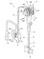
図3は一例として示す内視鏡の全体構成を表す斜視図である。
この内視鏡100は、本体操作部15と、この本体操作部15に連設され被検体内に挿入される内視鏡挿入部13とを備える。本体操作部15には、フレキシブルなLG軟性部となるユニバーサルコード41が接続され、このユニバーサルコード41の先端に、接続コネクタとしてのライトガイド(LG)コネクタ43が配置されている。また、LGコネクタ43には同じく他の接続コネクタとしてのビデオコネクタ45が接続されている。LGコネクタ43は図示しない光源装置に接続され、内視鏡挿入部13先端に照明光を導入し、ビデオコネクタ45は画像処理を行う図示しない信号処理装置に接続され、取得した観察画像を信号処理装置に出力する。
FIG. 3 is a perspective view illustrating an overall configuration of an endoscope shown as an example.
The
また、内視鏡100の本体操作部15には、内視鏡挿入部13の先端側で吸引、送気、送水を実施するためのボタンや、撮像時のシャッターボタン等の各種操作ボタン47が併設されるとともに、湾曲操作部17である一対のアングルノブ49A,49Bが設けられている。
The main
内視鏡挿入部13は、本体操作部15側から順に軟性部51、湾曲部11、及び先端部53で構成される。湾曲部11は、前述したように本体操作部15のアングルノブ49A,49Bを回動することによって遠隔的に湾曲操作され、これにより、先端部53を所望の方向に向けることができる。即ち、湾曲部11は、アングルノブ49Bの回動操作により、図3に点線で示す方向(左右湾曲方向と称する)へ湾曲し、アングルノブ49Aの回動操作により、前記左右方向と直交する方向(上下湾曲方向と称する)に湾曲する。
The
湾曲部11の湾曲動作は、内視鏡挿入部13に沿って内挿された一対の操作ワイヤ19により行なわれ、アングルノブ49A,49Bは、それぞれ個別でプーリ55に接続されて、このプーリ55に巻回される操作ワイヤ19を牽引、繰り出し操作する。図3では簡単化のため、アングルノブ49Bに接続されたプーリ55と、プーリ55に巻回された操作ワイヤ19等の1系統のみ示しているが、この内視鏡100は、アングルノブ49Aに対しても同様のプーリや操作ワイヤ等が設けられ、合計2系統の湾曲操作機構を備えている。そして、上記プーリ55と操作ワイヤ19は湾曲駆動部25として機能する。
The bending operation of the bending
操作ワイヤ19は、内視鏡挿入部13の先端部53に両端部が固定され、先端部53とは反対側のループ部分がプーリ55に巻回されている。このプーリ55をアングルノブ49Bの回動操作により回動駆動することで、操作ワイヤ19の牽引と繰り出しが行われ、湾曲部11が湾曲するようになっている。
Both ends of the
次に、プーリ55へ駆動モータ29の回転力を伝達する駆動力伝達機構31について説明する。
駆動力伝達機構31は、本体操作部15とLGコネクタ43とを連結するように設けられ、駆動モータ29の回転駆動軸に設けた入力側ギア57と、プーリ55を回動させる出力側ギア59とを有し、これら入力側ギア57と出力側ギア59との間が少なくとも2本のワイヤ部材61A,61Bで連結されている。ワイヤ部材61A,61Bのそれぞれは、入力側ギア57と螺合する駆動ギア63A,63Bに一端側が接続され、出力側ギア59と螺合する従動ギア65A,65Bに他端側が接続されている。
Next, the driving
The drive
また、アングルノブ49B、プーリ55、出力側ギア59は同軸上に一体に接続され、アングルノブ49Bを手動にて回動する操作力は、操作力検出部であるトルクセンサ21により検出される。
In addition, the
ここで、上記の駆動力伝達機構31の構成について、その具体的な構成を模式的に表した図4を参照して説明する。以降の説明では、図3に示す部材と同一の部材に対しては、同じ符号を付与することで、その説明は簡単化または省略する。
Here, the configuration of the driving
図4に示すように、ワイヤ部材61A,61Bは、多数の細線を特定の撚り方向に撚り合わせて形成したワイヤ67A,67Bを芯材とし、このワイヤ67A,67Bの外周に、ワイヤ67A,67Bを回転自在に被覆するアウターチューブ69A,69Bを有するフレキシブルシャフトである。なお、図中、ワイヤ67A,67Bは一部を露出させて表しているが、アウターチューブ69A,69Bによって全長にわたり被覆されている。
As shown in FIG. 4, the
駆動モータ29が入力側ギア57を回転駆動すると、入力側ギア57に螺合する駆動ギア63A,63Bが従動して回転し、駆動ギア63A,63Bにそれぞれ接合されたワイヤ部材61A,61Bを介して従動ギア65A,65Bが回転駆動されて出力側ギア59を回動させる。これによりプーリ55に回転力が加わり、湾曲部11(図1参照)を湾曲させる操作補助力が操作ワイヤ19に付与される。
When the
図5にワイヤ部材の端部の内部構造を示す一部断面構成図(a)と、A−A断面図(b)を示した。
ワイヤ部材61A,61Bは、回転自在なインナーシャフトとなるワイヤ67A,67Bと、例えば網線70の内外面を樹脂材料で被覆したアウターチューブ69A,69Bとを有し、端部にはワイヤ67A,67Bに接続され軸受部71に支持された回転軸73が設けられている。この回転軸73は、駆動ギア63A,63B、従動ギア65A,65Bに接続される。また、ワイヤ67A,67Bの外周面とアウターチューブ69A,69Bの内周面との間には、グリース等の潤滑剤75が封入されている。
FIG. 5 shows a partial cross-sectional configuration diagram (a) showing the internal structure of the end portion of the wire member, and an AA cross-sectional diagram (b).
The
このように、ワイヤ67A,67Bがアウターチューブ69A,69Bで被覆されることにより、ワイヤ67A,67Bが他の部品に干渉することなく、供給された回転力を確実に相手側に伝達できる。
Thus, by covering the
インナーシャフトであるワイヤ67A,67Bは、図4に示すように、多数の細線を撚り合わせる撚り方向が、最外層で互いに異なる方向にされている。一般にインナーシャフトは1本のワイヤ上に複数層のワイヤを巻き付けて製作されており、このワイヤの最外層の撚り方向によって右回転用と左回転用が存在する。ワイヤの最外層の撚り方向を回転方向に合わせると、捻りに強くなり、回転精度が高められるとともに、ワイヤの捻り方向の角度誤差および経年変化が減少する。本構成例では、駆動モータ29の回転方向が正逆いずれであっても、いずれかのワイヤ67A,67Bがワイヤの最外層の撚り方向と回転方向とが一致するので、高い角度精度で回転駆動力の伝達が可能となる。
As shown in FIG. 4, the wires 67 </ b> A and 67 </ b> B, which are inner shafts, have different twisting directions in which a large number of fine wires are twisted in different directions in the outermost layer. Generally, an inner shaft is manufactured by winding a plurality of layers of wire on a single wire, and there are a right rotation and a left rotation depending on the twisting direction of the outermost layer of the wire. When the twisting direction of the outermost layer of the wire is matched to the rotation direction, the twisting is strong, the rotation accuracy is improved, and the angle error and secular change in the twisting direction of the wire are reduced. In this configuration example, even if the rotation direction of the
なお、ワイヤ部材61A,61Bは2本に限らず、必要に応じて増設して複数本設けてもよい。本数を増やすことでより大きな駆動力を伝達でき、経年変化が低減され回転精度もより高められる。
The number of
次に、上記駆動力伝達機構31によるプーリ55の回転駆動動作について詳細に説明する。
図6は駆動力伝達機構による回転力の伝達の様子(a),(b)を示す説明図である。図6(a)に示すように、駆動モータ29を駆動して入力側ギア57をR1方向に回転させると、駆動ギア63AがR2方向に回転し、これがワイヤ部材61Aを介して従動ギア65AをR3方向に駆動する。すると、出力側ギア59はR4方向に回転してプーリ55を回転させ、図中矢印で示すように操作ワイヤ19の牽引および繰り出しが行われる。このとき、駆動ギア63Aの回転方向はワイヤ部材61Aのワイヤ最外層における撚り方向と一致(図4参照)しており、駆動モータ29からの回転力は確実かつ高精度で出力側ギア59に伝達される。
Next, the rotational driving operation of the
FIG. 6 is an explanatory diagram showing states (a) and (b) of transmission of rotational force by the driving force transmission mechanism. As shown in FIG. 6A, when the
一方、駆動ギア63BはR5方向に回転して、その回転力がワイヤ部材61Bと従動ギア65Bを介して出力側ギア59に伝達されるが、この場合の回転方向は、ワイヤ部材61Bのワイヤ最外層における撚り方向とは逆方向であるため、伝達効率が低く、ワイヤ部材61Aによる駆動力伝達が支配的となる。
On the other hand, the
また、図6(b)に示すように、駆動モータ29を駆動して入力側ギア57を前述のR1方向とは逆のR6方向に回転させると、駆動ギア63BがR7方向に回転し、これがワイヤ部材61Bを介して従動ギア65BをR8方向に駆動する。すると、出力側ギア59はR9方向に回転してプーリ55を回転させ、図中矢印で示すように、上記図6(a)の場合とは反対方向の操作ワイヤ19の牽引および繰り出しが行われる。このとき、駆動ギア63Bの回転方向はワイヤ部材61Bのワイヤ最外層における撚り方向と一致(図4参照)しており、駆動モータ29からの回転力は確実かつ高精度で出力側ギア59に伝達される。
Further, as shown in FIG. 6B, when the
一方、駆動ギア63AはR10方向に回転して、その回転力がワイヤ部材61Aと従動ギア65Aを介して出力側ギア59に伝達されるが、この場合の回転方向は、ワイヤ部材61Aのワイヤ最外層における撚り方向とは逆方向であるため、伝達効率が低く、ワイヤ部材61Bによる駆動力伝達が支配的となる。
On the other hand, the
上記のように、出力側ギア59を回転させる主な駆動力伝達経路は、ワイヤ部材61A,61Bのいずれか一方の経路となるため、主な駆動力伝達経路でない側は、駆動モータ29の回転力を出力側ギア59に伝達する機能を停止させてもよい。例えば、駆動ギア63A,63Bにワンウェイクラッチを配置して、駆動ギア63AはR2方向のみ回転力をワイヤ部材61Aに伝達し、駆動ギア63BはR7方向のみ回転力をワイヤ部材61Bに伝達する構成とする。この場合、駆動モータ29の負荷が軽減される。また、ワンウェイクラッチは従動ギア65A,65B側に設けてもよく、その場合は湾曲操作部17(図4参照)に加える操作力を軽減できる。
As described above, the main driving force transmission path for rotating the
次に、ワイヤ部材61A,61Bによる回転力の伝達特性について説明する。
図7は各ワイヤ部材を単独で用いた場合のワイヤ回転角と伝達されたトルクとの関係を示すグラフ(a),(b)である。図7(a)に示すように、図4,6に示したワイヤ67Aの駆動ギア63A側で加えるワイヤ回転角φに対して従動ギア65A側で発生するトルクは、回転方向がR2方向(ワイヤ67Aの最外層における撚り方向)では略比例的に増加する特性となるが、逆の回転方向では階段状となって、回転の伝達精度が低下する。ワイヤ67Bも同様で、図7(b)に示すように、回転方向がR7方向(ワイヤ67Bの最外層における撚り方向)では略比例的に増加する特性となるが、逆の回転方向では階段状となって、回転の伝達精度が低下する。
Next, the transmission characteristic of the rotational force by the
FIG. 7 is graphs (a) and (b) showing the relationship between the wire rotation angle and the transmitted torque when each wire member is used alone. As shown in FIG. 7A, the torque generated on the driven
そこで、前述したように最外層の撚り方向が互いに異なる少なくとも2本のワイヤを併用して駆動モータ29の回転力を伝達することで、最外層の撚り方向が回転方向と一致するワイヤが主な駆動力伝達ワイヤとなる。これにより、駆動モータ29の回転と伝達されるトルクとの関係は、図8のように主な駆動力伝達ワイヤの伝達特性を合成した関係となり、回転方向の正逆ともに階段状にならない略比例的な関係を呈する。
Therefore, as described above, by using at least two wires having different twist directions in the outermost layer in combination and transmitting the rotational force of the
また、主な駆動力伝達経路でない側を前述のワンウェイクラッチ等により回転力伝達機能を停止した場合、図8に示す伝達トルクの特性は、より一層線形性が高められる。 Further, when the rotational force transmission function is stopped by the above-described one-way clutch or the like on the side that is not the main driving force transmission path, the linearity is further improved in the characteristics of the transmission torque shown in FIG.
次に、以上説明した内視鏡100の構成により、湾曲操作部17に操作補助力を付与するための具体的な制御について説明する。
図9に内視鏡100の操作補助力の付与手順をフローチャートで示した。内視鏡100を使用可能な状態にしたときに、次の手順で操作補助力を発生させ、パワーアシスト機能を発揮する。
Next, specific control for applying an operation assisting force to the
FIG. 9 is a flowchart showing an operation assisting force application procedure for the
まず、内視鏡100の制御部23に、この内視鏡100固有の各種パラメータを設定する(S1)。各種パラメータには、図3に示すトルクセンサ21により検出された術者の手動操作力に対する、発生させる操作補助力の大きさを表す対応テーブル情報、および、駆動モータ29への入力電力と、駆動モータ29をこの入力電力で駆動させて発生する実操作補助力との関係の情報が少なくとも含まれる。
First, various parameters unique to the
前者の対応テーブル情報は、図1に示す記憶部39に記憶されており、図2に示される湾曲部の湾曲角度と湾曲に必要となるトルクとの関係において、操作補助力であるアシストトルクの大きさが湾曲角度毎に規定されている。このテーブル情報は、術者にとって良好な操作性が得られるように任意に設定できる。また、内視鏡100の手技内容に応じて適宜テーブル情報を変更し、内視鏡の使用目的に応じた適切な操作性を得るようにしてもよい。
The former correspondence table information is stored in the
一方、後者の実操作補助力との関係の情報は、駆動モータ29の種類や駆動力伝達機構31等によって決まり、また、経時的な変化も生じる。この情報には、図4に示すワイヤ部材61A,61Bの一端側の回転駆動側(入力側ギア57)と、他端側の回転力伝達側(出力側ギア59)との間の回転角度の誤差情報が含まれる。
On the other hand, the information on the relationship with the latter actual operation assisting force is determined by the type of the driving
次に、図3に示す内視鏡挿入部13を観察対象の体腔内に挿入して、先端部53を所望の方向に向ける際に、術者は湾曲操作部17としてのアングルノブ49A,49Bを手動操作する(S2)。
Next, when inserting the
このときのアングルノブ49B(49Aも同様)への操作力をトルクセンサ21で検出する(S3)。そして、図2に示すようなテーブル情報を記憶部39から参照して、検出した操作力(トルクTw)に対応する湾曲部11の湾曲角度θを求め、この湾曲角度θに至らせるに必要なアシストトルクTaを求める(S4)。
At this time, the operating force to the
そして、この必要なアシストトルクTaを得るために、駆動モータ29の駆動条件を決定する(S5)。具体的には、アシストトルクTaが得られるワイヤ67A,67Bのワイヤ回転角φを求め、このワイヤ回転角φが得られるように駆動モータ29を駆動する。このとき、図10にワイヤ回転角に対するトルクの関係を示すように、内視鏡100の個体差の他に、ワイヤ67A,67Bの経年変化等によっても回転角度の誤差が生じるため、所望のトルクが得られるワイヤ回転角φを都度補正して求める。
Then, in order to obtain the necessary assist torque Ta, the drive condition of the
つまり、ワイヤ回転角と発生するトルクの特性曲線は常に一定ではなく、内視鏡の使用頻度等に応じて異なるため、最新の特性曲線に基づいて駆動モータ29の駆動条件を決定し、駆動モータ29を駆動する(S6)。
In other words, the characteristic curve of the wire rotation angle and the generated torque is not always constant, and varies depending on the usage frequency of the endoscope. Therefore, the drive condition of the
これにより、駆動モータ29の駆動により発生するアシストトルクTaと、実際に湾曲操作部17に加えた操作力によるトルクTwとを合わせたトルクがプーリ55に付与される。そして、プーリ55の回動による操作ワイヤ19の牽引および繰り出しによって、内視鏡挿入部13の湾曲部11が湾曲し、先端部53を所望の湾曲角度に正確に湾曲させることができる。
As a result, a torque obtained by combining the assist torque Ta generated by driving the
この内視鏡によれば、トルクセンサ21で検出された手動操作の操作力に基づき、記憶部39の対応テーブル情報を参照して、対応する操作補助力を求め、この操作補助力を駆動モータ29を駆動して、いち早く手動操作の操作力に加えることができる。そのため、必要な操作補助力を高精度で、かつ、応答性よく作用させることができ、良好な操作性が得られる。
According to this endoscope, based on the operation force of the manual operation detected by the
ここで、図10に示す特性曲線は、内視鏡使用前に予め設定することが望ましい。例えば、内視鏡使用前に、駆動モータ29への入力電力と、この入力電力による駆動モータ29の駆動によってプーリ55で実際に発生する実操作補助力との関係を測定して求め、得られた情報に基づく特性曲線を記憶部39に記憶しておく。そして内視鏡使用時に、アングルノブ49B(49Aも同様)への操作力をトルクセンサ21で検出して、必要なアシストトルクTaを求め、このアシストトルクTaを得るために必要な駆動モータ29の入力電力を、記憶部39に記憶された上記の特性曲線に基づいて決定する。これによれば、駆動力伝達機構の伝達効率や、ワイヤ67A,67Bの経年変化等の変動が加味された適正なアシストトルクを発生させることができ、常に最新の状態に対する補正情報を用いた高精度な駆動が可能となる。
Here, the characteristic curve shown in FIG. 10 is desirably set in advance before using the endoscope. For example, before using the endoscope, it is obtained by measuring the relationship between the input power to the
なお、入力電力としては、回転駆動力発生部である駆動モータ29が直流モータや交流モータ、サーボモータである場合は電圧値、電流値等を制御パラメータとし、ステッピングモータである場合はパルス数やデューティ比等を制御パラメータとすることができる。さらに回転駆動力発生部は、モータに限らず他のアクチュエータで代用することも可能である。
As the input power, when the
以上説明した内視鏡の制御は、湾曲部11の上下湾曲方向と左右湾曲方向の異なる2方向に対して同時に適用できる。その場合、アングルノブ49A,49Bのそれぞれに対応させて、上述したトルクセンサ21、プーリ55、操作ワイヤ19、駆動モータ29とこれに接続される駆動力伝達機構31、および制御部23、等を備えた構成にすればよい。
The endoscope control described above can be applied simultaneously to two different directions, ie, the bending direction of the bending
なお、駆動モータ29は、上記例ではLGコネクタ43内に配置しているが、ビデオコネクタ45内に配置してもよく、複数の駆動モータを使用する場合等にはLGコネクタ43とビデオコネクタ45の双方に分散配置してもよい。いずれの場合も、内視鏡に現存する附帯部である接続コネクタを利用した簡単な配置構成にできる。
The
さらに、駆動モータを、本体操作部15にフレキシブルな軟性部を介して接続される専用の附帯部(図示せず)を別途に設け、この附帯部内に配置してもよい。その場合、駆動モータやこれに接続される駆動機構のサイズや重量の制約が緩和されて、より大きな操作補助力、より正確な操作補助力を発生させることができる。
Furthermore, the drive motor may be separately provided with a dedicated auxiliary part (not shown) connected to the main
また、図1に示す制御部23、記憶部39は、本体操作部15内に配置する以外にも、例えば接続コネクタ27等の他の部位に配置してもよく、さらには、内視鏡の個体識別を可能にして、光源・信号処理装置35等の他の部位に配置してもよい。
Further, the
次に、上記構成の内視鏡100の変形例について以下に説明する。
図11は第1の変形例としての駆動力伝達機構の構成および動作例(a),(b)を示す構成図である。同図において、図6に示す部材と同一の部材は同一の符号を付与している。
この変形例における駆動力伝達機構31Aは、駆動ギア63A、63Bのそれぞれ個別に駆動モータ29A,29Bを備えている。即ち、駆動力伝達機構31Aは、湾曲操作部を回動させる出力側ギア59を有し、ワイヤ部材61A,61Bが出力側ギア59と螺合する従動ギア65A,65Bにそれぞれ接続されている。また、ワイヤ部材61A,61Bの従動ギア65A.65Bの接続側とは反対側の端部には、それぞれ対応する駆動モータ29A,29Bの回転駆動軸が接続されている。
Next, a modified example of the
FIG. 11 is a configuration diagram showing a configuration and operation examples (a) and (b) of a driving force transmission mechanism as a first modification. In the figure, the same members as those shown in FIG. 6 are given the same reference numerals.
The driving
この駆動力伝達機構31Aによれば、各ワイヤ部材61A,61Bを個別に駆動モータ29A,29Bにより駆動するので、種々の制御パターンを予め用意し、これを任意に適用することが可能となり、複雑な駆動動作を簡単に実現できる。例えば、図11(a)に示すように、駆動モータ29Aの駆動により、ワイヤ部材61Aを介して出力側ギア59をR4方向に回転駆動しているときに、図11(b)に示すように、駆動モータ29Aを停止して出力側ギア59を停止駆動するとともに、駆動モータ29BをR6方向に駆動して、ワイヤ部材61Bを介して出力側ギア59にブレーキ力を発生させることができる。これによれば、プーリ55と操作ワイヤ19の動作を瞬時に停止させることができる。また、出力側ギア59を逆回転させる場合も同様に、ブレーキ力の発生が可能となる。これにより、発生させる補助操作力の応答性を高めることができ、湾曲操作の操作性を更に向上できる。
According to this driving
図12は第2の変形例としてのライトガイド軟性部の断面図である。
この変形例におけるLG軟性部33は、図3に示されるユニバーサルコード41であり、ワイヤ部材61A,61BのアウターチューブをLG軟性部33自体で形成している。LG軟性部33は、一般には照明光を伝送するライトガイド77、内視鏡挿入部の先端からエアや水を噴出させる送気・送水チューブ79、吸引を行うための吸引チューブ81、各種信号線等のケーブル83類が内包されており、アウターチューブを有するワイヤ部材を更に組み入れると、LG軟性部33の大径化が避けられない。
FIG. 12 is a cross-sectional view of a light guide soft part as a second modification.
The LG
そこで、ワイヤ部材のうち比較的大きな断面積を有するアウターチューブをLG軟性部33で形成する、つまり、LG軟性部33の一部をアウターチューブとして利用して、ワイヤ67A,67Bのみ挿通させることで、LG軟性部33の径を小さく抑え、経済的な構成にできる。
Therefore, an outer tube having a relatively large cross-sectional area of the wire member is formed by the LG
以上の通り、本明細書には次の事項が開示されている。
(1) 被検体内に挿入され先端部付近に湾曲自在な湾曲部を有する内視鏡挿入部と、該内視鏡挿入部の基端側に連設された本体操作部と、該本体操作部にフレキシブルな軟性部を介して接続された附帯部と、を有する内視鏡であって、
前記本体操作部に設けられ前記湾曲部を所望の方向へ湾曲させる手動操作を行う湾曲操作部と、
前記湾曲操作部と前記湾曲部とを連結して、前記湾曲操作部への操作に応じて前記湾曲部を湾曲させる湾曲駆動部と、
前記湾曲操作部に加えた操作力を検出する操作力検出部と、
前記操作力検出部により検出された操作力に対応する操作補助力を求める操作補助力演算部と、
駆動力伝達機構を介して前記湾曲駆動部に駆動力を印加して前記操作補助力演算部で求めた操作補助力を発生させる回転駆動力発生部と、
を備え、
前記回転駆動力発生部を前記附帯部に配置した内視鏡。
この内視鏡によれば、本体操作部に軟性部を介して接続された附帯部に回転駆動力発生部が配置されるので、湾曲部の湾曲させる操作補助力を大きく、高精度に発生させるために回転駆動力発生部の能力を高める場合でも、回転駆動力発生部の大型化、重量化する影響を受けることがない。そのため、本体操作部はサイズや重量を増加させることなく、高い操作性を維持して操作補助力を湾曲駆動部に付与できる。これにより、本体操作部が軽量に維持されて、術者の操作疲労を低減した操作性の良いパワーアシスト機能を発揮できる。
As described above, the following items are disclosed in this specification.
(1) An endoscope insertion portion that is inserted into a subject and has a bending portion that can be bent in the vicinity of the distal end portion, a main body operation portion that is connected to the proximal end side of the endoscope insertion portion, and the main body operation An endoscope having a supplementary part connected to the part via a flexible flexible part,
A bending operation unit that is provided in the main body operation unit and performs a manual operation for bending the bending unit in a desired direction;
A bending drive unit that connects the bending operation unit and the bending unit to bend the bending unit in response to an operation to the bending operation unit;
An operation force detection unit for detecting an operation force applied to the bending operation unit;
An operation assisting force calculating unit for obtaining an operation assisting force corresponding to the operation force detected by the operation force detecting unit;
A rotational driving force generating unit that applies a driving force to the bending driving unit via a driving force transmission mechanism to generate the operation assisting force obtained by the operation assisting force calculating unit;
With
The endoscope which has arrange | positioned the said rotational driving force generation part in the said incidental part.
According to this endoscope, since the rotational driving force generator is disposed in the auxiliary part connected to the main body operation part via the soft part, the operation assisting force for bending the bending part is generated with high accuracy. Therefore, even when the capability of the rotational driving force generation unit is increased, the size and weight of the rotational driving force generation unit are not affected. Therefore, the main body operation unit can maintain the high operability without increasing the size and weight, and can apply the operation assisting force to the bending drive unit. Thereby, the main body operation part is kept lightweight, and the power assist function with good operativity which reduced operation fatigue of the operator can be exhibited.
(2) (1)の内視鏡であって、
前記駆動力伝達機構が、多数の細線を撚り合わせて形成したワイヤを用い、該ワイヤの細線のうち最外層の撚り方向を回転方向にして前記回転駆動力発生部の回転力を伝達する内視鏡。
この内視鏡によれば、附帯部と本体操作部との間の軟性部でワイヤにより駆動力が伝達されるため、軟性部を細径にでき、また、捻り力に強いワイヤを介して回転力を伝達するため、回転駆動の角度精度が高められ、しかもワイヤの経年変化を低減できる。
(2) The endoscope according to (1),
An internal view in which the driving force transmission mechanism uses a wire formed by twisting a large number of fine wires, and transmits the rotational force of the rotational driving force generating unit with the twist direction of the outermost layer among the fine wires of the wire as the rotational direction. mirror.
According to this endoscope, since the driving force is transmitted by the wire at the soft part between the accessory part and the main body operation part, the soft part can be made to have a small diameter and can be rotated via a wire that is strong against twisting force. Since the force is transmitted, the angular accuracy of the rotational drive can be improved and the secular change of the wire can be reduced.
(3) (2)の内視鏡であって、
前記駆動力伝達機構が、前記第1のワイヤと、該第1のワイヤとは前記最外層の撚り方向が異なる第2のワイヤとの少なくとも2本のワイヤを併用して前記回転力を伝達する内視鏡。
この内視鏡によれば、回転方向が正逆いずれであっても、捻り方向に強い撚り方向のいずれかのワイヤが回転力を伝達するため、いずれの回転方向であっても回転駆動時の角度精度が高められる。また、操作補助力となる駆動力を複数のワイヤにより伝達するため、より大きな駆動力を伝達でき、回転精度もより高められる。
(3) The endoscope according to (2),
The driving force transmission mechanism transmits the rotational force by using at least two wires of the first wire and a second wire having a twist direction of the outermost layer different from that of the first wire. Endoscope.
According to this endoscope, even if the rotation direction is forward or reverse, any wire in the twist direction that is strong in the twist direction transmits the rotational force. Angular accuracy is increased. Further, since the driving force serving as the operation assisting force is transmitted by the plurality of wires, a larger driving force can be transmitted and the rotation accuracy can be further improved.
(4) (3)の内視鏡であって、
前記駆動力伝達機構が、前記回転駆動力発生部の回転駆動軸に設けた入力側ギアと、前記湾曲駆動部を回動させる出力側ギアとを有し、前記入力側ギアと前記出力側ギアとの間が複数本の前記ワイヤで連結されるとともに、該ワイヤのそれぞれが、前記入力側ギアと螺合する駆動ギアに一端側が接続され、前記出力側ギアと螺合する従動ギアに他端側が接続されている内視鏡。
この内視鏡によれば、回転駆動力発生部が入力側ギアを回転駆動すると、入力側ギアに螺合する駆動ギアが回転し、駆動ギアに接合されたワイヤを介して従動ギアが回転駆動されて出力側ギアを回動させる。これにより、湾曲駆動部を駆動する操作補助力が発生して湾曲部の湾曲操作が補助される。
(4) The endoscope according to (3),
The drive force transmission mechanism includes an input side gear provided on a rotation drive shaft of the rotation drive force generation unit, and an output side gear that rotates the bending drive unit, and the input side gear and the output side gear. Are connected to each other by a plurality of the wires, and one end side of each of the wires is connected to a drive gear that is screwed with the input side gear, and the other end is a driven gear that is screwed to the output side gear. Endoscope with side connected.
According to this endoscope, when the rotational driving force generation unit rotationally drives the input side gear, the driving gear screwed to the input side gear rotates, and the driven gear rotates through the wire joined to the driving gear. Then, the output side gear is rotated. Thereby, an operation assisting force for driving the bending drive unit is generated, and the bending operation of the bending unit is assisted.
(5) (3)の内視鏡であって、
前記駆動力伝達機構が、前記湾曲操作部を回動させる出力側ギアを有し、複数の前記ワイヤが前記出力側ギアと螺合する複数の従動ギアにそれぞれ接続され、前記ワイヤの前記従動ギアの接続側とは反対側の端部に、複数の回転駆動力発生部のうち、それぞれ対応する回転駆動力発生部の回転駆動軸が接続された内視鏡。
この内視鏡によれば、各ワイヤをそれぞれ個別に用意された回転駆動力発生部により駆動するので、複雑な駆動動作を簡単に実現できる。例えば一方のワイヤにより湾曲駆動部の駆動を停止させるとともに、他方のワイヤによりブレーキ力を発生させて、瞬時に湾曲駆動を停止する等の多彩な制御が可能となる。
(5) The endoscope according to (3),
The driving force transmission mechanism has an output side gear for rotating the bending operation unit, and a plurality of the wires are respectively connected to a plurality of driven gears screwed with the output side gear, and the driven gears of the wires An endoscope in which a rotation drive shaft of a corresponding rotation drive force generation unit among a plurality of rotation drive force generation units is connected to an end opposite to the connection side.
According to this endoscope, since each wire is driven by the rotational driving force generator prepared individually, a complicated driving operation can be easily realized. For example, it is possible to perform various controls such as stopping the driving of the bending drive unit with one wire and generating a braking force with the other wire to stop the bending drive instantaneously.
(6) (2)〜(5)のいずれか1つの内視鏡であって、
前記ワイヤの外周に、該ワイヤを回転自在に被覆するアウターチューブを配置した内視鏡。
この内視鏡によれば、ワイヤをアウターチューブで被覆することにより、ワイヤが他の部品に干渉することなく、伝達された回転力を確実に湾曲駆動部に伝えることができる。
(6) The endoscope according to any one of (2) to (5),
An endoscope in which an outer tube that rotatably covers the wire is disposed on the outer periphery of the wire.
According to this endoscope, by covering the wire with the outer tube, the transmitted rotational force can be reliably transmitted to the bending drive unit without the wire interfering with other components.
(7) (6)の内視鏡であって、
前記アウターチューブが前記本体操作部と前記附帯部とを接続する軟性部で形成された内視鏡。
この内視鏡によれば、軟性部自体でアウターチューブを形成することで、軟性部の径を小さく抑え、経済的な構成にできる。
(7) The endoscope according to (6),
An endoscope in which the outer tube is formed of a soft part that connects the main body operation part and the auxiliary part.
According to this endoscope, by forming the outer tube with the soft portion itself, the diameter of the soft portion can be suppressed to be small and an economical configuration can be achieved.
(8) (1)〜(7)のいずれか1つの内視鏡であって、
前記附帯部が、前記内視鏡挿入部の先端に照明光を供給する照明装置との接続用コネクタである内視鏡。
この内視鏡によれば、照明装置との接続用コネクタに回転駆動力発生部を配置することで、内視鏡に現存する附帯部を利用した、簡単な回転駆動力発生部の配置構成にできる。
(8) The endoscope according to any one of (1) to (7),
An endoscope in which the auxiliary portion is a connector for connection with an illumination device that supplies illumination light to the distal end of the endoscope insertion portion.
According to this endoscope, by arranging the rotational driving force generating portion in the connector for connection with the illumination device, the arrangement configuration of the simple rotational driving force generating portion using the auxiliary portion existing in the endoscope can be realized. it can.
(9) (1)〜(7)のいずれか1つの内視鏡であって、
前記附帯部が、前記内視鏡挿入部の先端の撮像部から出力される撮像信号を処理する信号処理装置との接続用コネクタである内視鏡。
この内視鏡によれば、信号処理装置との接続用コネクタに回転駆動力発生部を配置することで、内視鏡に現存する附帯部を利用した、簡単な回転駆動力発生部の配置構成にできる。
(9) The endoscope according to any one of (1) to (7),
An endoscope in which the auxiliary part is a connector for connection with a signal processing device that processes an imaging signal output from an imaging part at the tip of the endoscope insertion part.
According to this endoscope, an arrangement configuration of a simple rotational driving force generation unit using an auxiliary part existing in the endoscope by arranging the rotational driving force generation unit on the connector for connection with the signal processing device. Can be.
(10) (2)〜(9)のいずれか1つの内視鏡であって、
前記操作補助力演算部が前記検出された操作力に応じた操作保持力を求める際に参照され、前記検出された操作力に対応する操作補助力の大きさを表す対応テーブル情報の記憶された記憶部を更に備えた内視鏡。
この内視鏡によれば、記憶部の対応テーブル情報を参照して、検出された操作力に対応する操作補助力を求めるため、必要な操作補助力を的確に発生させることができる。また、術者が加える操作力に対応する操作補助力を、対応テーブル情報の変更により任意に設定できるので、術者が良好な操作性が得られるよう、容易に調整が可能になる。
(10) The endoscope according to any one of (2) to (9),
The operation assisting force calculation unit is referred to when obtaining the operation holding force according to the detected operation force, and correspondence table information indicating the magnitude of the operation assisting force corresponding to the detected operation force is stored. An endoscope further comprising a storage unit.
According to this endoscope, the operation assisting force corresponding to the detected operation force is obtained with reference to the correspondence table information in the storage unit, so that the necessary operation assisting force can be accurately generated. In addition, since the operation assisting force corresponding to the operation force applied by the surgeon can be arbitrarily set by changing the correspondence table information, it is possible to easily adjust the surgeon to obtain good operability.
(11) (10)の内視鏡であって、
前記記憶部がさらに、前記回転駆動力発生部への入力電力と、前記回転駆動力発生部を前記入力電力で駆動させて発生する実操作補助力との関係の情報を記憶し、
前記操作補助力演算部が前記関係に基づいて前記回転駆動力発生部の駆動電力を決定する内視鏡。
この内視鏡によれば、回転駆動力発生部への入力電力と、実際に発生する操作補助力との関係から回転駆動力発生部の駆動電力を決定するため、駆動力伝達機構の伝達効率等を加味した駆動制御が行え、操作補助力を高精度に湾曲駆動部へ付与できる。
(11) The endoscope according to (10),
The storage unit further stores information on the relationship between the input power to the rotational driving force generation unit and the actual operation assisting force generated by driving the rotational driving force generation unit with the input power,
The endoscope in which the operation assisting force calculation unit determines the driving power of the rotational driving force generation unit based on the relationship.
According to this endoscope, since the driving power of the rotational driving force generator is determined from the relationship between the input power to the rotational driving force generator and the operation assist force that is actually generated, the transmission efficiency of the driving force transmission mechanism is determined. Thus, it is possible to perform drive control in consideration of the above, and to apply an operation assisting force to the bending drive unit with high accuracy.
(12) (11)の内視鏡であって、
前記回転駆動力発生部への入力電力と前記実操作補助力との関係の情報が、前記ワイヤの一端側の回転駆動側と、他端側の回転力伝達側との間の回転角度の誤差情報を含む内視鏡。
この内視鏡によれば、操作補助力の変動要因であるワイヤの経年変化に起因した回転角度の誤差情報に基づいて実操作補助力を求めることで、操作補助力を簡単にしかも正確に求めることができる。
(12) The endoscope according to (11),
Information on the relationship between the input power to the rotational driving force generator and the actual operation assisting force is an error in the rotational angle between the rotational driving side on one end side of the wire and the rotational force transmitting side on the other end side. An endoscope that contains information.
According to this endoscope, the operation assistance force can be obtained easily and accurately by obtaining the actual operation assistance force based on the error information of the rotation angle caused by the secular change of the wire, which is a variation factor of the operation assistance force. be able to.
(13) (11)または(12)の内視鏡であって、
前記回転駆動力発生部への入力電力と前記実操作補助力との関係の情報を内視鏡使用前に更新する情報更新手段を備えた内視鏡。
この内視鏡によれば、回転駆動力発生部への入力電力と実操作補助力との関係を内視鏡使用前に求めて更新することで、常に最新の状態における情報を用いて高精度に操作補助力を発生させることが可能となる。
(13) The endoscope according to (11) or (12),
An endoscope provided with information updating means for updating information on the relationship between the input power to the rotational driving force generator and the actual operation assisting force before using the endoscope.
According to this endoscope, the relationship between the input power to the rotational driving force generator and the actual operation assisting force is obtained and updated before using the endoscope, so that the information in the latest state is always used with high accuracy. It is possible to generate an operation assisting force.
(14) (1)〜(13)のいずれか1つの内視鏡であって、
前記湾曲操作部が、前記内視鏡挿入部に沿って内挿された一対の操作ワイヤの牽引と繰り出し操作により前記湾曲部を湾曲させる内視鏡。
この内視鏡によれば、湾曲操作部の回動操作が操作ワイヤに伝達されて、湾曲部を所望の方向に湾曲させることができる。
(14) The endoscope according to any one of (1) to (13),
An endoscope in which the bending operation portion bends the bending portion by pulling and feeding a pair of operation wires inserted along the endoscope insertion portion.
According to this endoscope, the turning operation of the bending operation unit is transmitted to the operation wire, and the bending unit can be bent in a desired direction.
(15) (14)の内視鏡であって、
前記湾曲操作部が、前記湾曲部の上下湾曲方向と左右湾曲方向のそれぞれに対して設けられ、各湾曲操作部に対応して、前記操作力検出部、前記湾曲駆動部、前記操作補助力演算部、前記駆動力伝達機構、および前記回転駆動力発生部を設けた内視鏡。
この内視鏡によれば、湾曲部の上下湾曲方向、左右湾曲方向のそれぞれに対して同時に駆動が行え、任意の方向の湾曲操作を簡単に行うことができる。
(15) The endoscope according to (14),
The bending operation unit is provided for each of the up and down bending direction and the left and right bending direction of the bending unit, and the operation force detecting unit, the bending driving unit, and the operation assisting force calculation corresponding to each bending operation unit. The endoscope which provided the part, the said driving force transmission mechanism, and the said rotational driving force generation part.
According to this endoscope, it is possible to simultaneously drive in the vertical bending direction and the horizontal bending direction of the bending portion, and it is possible to easily perform a bending operation in an arbitrary direction.
11 湾曲部
13 内視鏡挿入部
15 本体操作部
17 湾曲操作部
19 操作ワイヤ
21 トルクセンサ(操作力検出部)
23 制御部(操作補助力演算部)
25 湾曲駆動部
27 接続コネクタ
29、29A,29B 駆動モータ(回転駆動力発生部)
31,31A 駆動力伝達機構
33 ライトガイド軟性部
35 光源・信号処理装置
39 記憶部
41 ユニバーサルコード
43 ライトガイドコネクタ
45 ビデオコネクタ
47 操作ボタン
49A,49B アングルノブ
51 軟性部
53 先端部
55 プーリ
57 入力側ギア
59 出力側ギア
61A,61B ワイヤ部材
63A,63B 駆動ギア
65A,65B 従動ギア
67A,67B ワイヤ
69A,69B アウターチューブ
DESCRIPTION OF
23 Control unit (operation assisting force calculation unit)
25 bending drive part 27
31, 31A Driving
Claims (12)
前記本体操作部に設けられ前記湾曲部を所望の方向へ湾曲させる手動操作を行う湾曲操作部と、
前記湾曲操作部と前記湾曲部とを連結して、前記湾曲操作部への操作に応じて前記湾曲部を湾曲させる湾曲駆動部と、
前記湾曲操作部に加えた操作力を検出する操作力検出部と、
前記操作力検出部により検出された操作力に対応する操作補助力を求める操作補助力演算部と、
前記附帯部に配置され、駆動力伝達機構を介して前記湾曲駆動部に駆動力を印加して前記操作補助力演算部で求めた操作補助力を発生させる回転駆動力発生部と、
前記検出された操作力に対応する前記操作補助力の大きさを表す対応テーブル情報の記憶された記憶部と、
を備え、
前記操作補助力演算部が、前記対応テーブル情報を参照して前記検出された操作力に応じた前記操作補助力を求め、
前記駆動力伝達機構が、多数の細線を撚り合わせて形成したワイヤを用い、該ワイヤの細線のうち最外層の撚り方向を回転方向にして前記回転駆動力発生部の回転力を伝達する内視鏡。 An endoscope insertion portion that is inserted into the subject and has a bending portion that is freely bendable near the distal end portion, a main body operation portion that is connected to the proximal end side of the endoscope insertion portion, and a flexible operation to the main body operation portion An endoscope having an attached portion connected via a flexible portion,
A bending operation unit that is provided in the main body operation unit and performs a manual operation for bending the bending unit in a desired direction;
A bending drive unit that connects the bending operation unit and the bending unit to bend the bending unit in response to an operation to the bending operation unit;
An operation force detection unit for detecting an operation force applied to the bending operation unit;
An operation assisting force calculating unit for obtaining an operation assisting force corresponding to the operation force detected by the operation force detecting unit;
A rotational driving force generating unit that is disposed in the auxiliary part and applies the driving force to the bending driving unit via a driving force transmission mechanism to generate the operation assisting force obtained by the operation assisting force calculating unit;
A storage unit storing correspondence table information representing the magnitude of the operation assistance force corresponding to the detected operation force;
With
The operation assisting force calculation unit obtains the operation assisting force according to the detected operation force with reference to the correspondence table information ,
An internal view in which the driving force transmission mechanism uses a wire formed by twisting a large number of fine wires, and transmits the rotational force of the rotational driving force generating unit with the twist direction of the outermost layer among the fine wires of the wire as the rotational direction. mirror.
前記駆動力伝達機構が、第1のワイヤと、該第1のワイヤとは前記最外層の撚り方向が異なる第2のワイヤとの少なくとも2本のワイヤを併用して前記回転力を伝達する内視鏡。The driving force transmission mechanism transmits the rotational force by using at least two wires of a first wire and a second wire having a twist direction of the outermost layer different from that of the first wire. Endoscope.
前記駆動力伝達機構が、前記回転駆動力発生部の回転駆動軸に設けた入力側ギアと、前記湾曲駆動部を回動させる出力側ギアとを有し、前記入力側ギアと前記出力側ギアとの間が複数本の前記ワイヤで連結されるとともに、該ワイヤのそれぞれが、前記入力側ギアと螺合する駆動ギアに一端側が接続され、前記出力側ギアと螺合する従動ギアに他端側が接続されている内視鏡。The drive force transmission mechanism includes an input side gear provided on a rotation drive shaft of the rotation drive force generation unit, and an output side gear that rotates the bending drive unit, and the input side gear and the output side gear. Are connected to each other by a plurality of the wires, and one end side of each of the wires is connected to a drive gear that is screwed with the input side gear, and the other end is a driven gear that is screwed to the output side gear. Endoscope with side connected.
前記駆動力伝達機構が、前記湾曲操作部を回動させる出力側ギアを有し、複数の前記ワイヤが前記出力側ギアと螺合する複数の従動ギアにそれぞれ接続され、前記ワイヤの前記従動ギアの接続側とは反対側の端部に、複数の前記回転駆動力発生部のうち、それぞれ対応する回転駆動力発生部の回転駆動軸が接続された内視鏡。The driving force transmission mechanism has an output side gear for rotating the bending operation unit, and a plurality of the wires are respectively connected to a plurality of driven gears screwed with the output side gear, and the driven gears of the wires An endoscope in which a rotation drive shaft of a corresponding rotation drive force generation unit among the plurality of rotation drive force generation units is connected to an end opposite to the connection side.
前記ワイヤの外周に、該ワイヤを回転自在に被覆するアウターチューブを配置した内視鏡。An endoscope in which an outer tube that rotatably covers the wire is disposed on the outer periphery of the wire.
前記アウターチューブが、前記本体操作部と前記附帯部とを接続する軟性部で形成された内視鏡。An endoscope in which the outer tube is formed of a soft part that connects the main body operation part and the auxiliary part.
前記附帯部が、前記内視鏡挿入部の先端に照明光を供給する照明装置との接続用コネクタである内視鏡。An endoscope in which the auxiliary portion is a connector for connection with an illumination device that supplies illumination light to the distal end of the endoscope insertion portion.
前記附帯部が、前記内視鏡挿入部の先端の撮像部から出力される撮像信号を処理する信号処理装置との接続用コネクタである内視鏡。An endoscope in which the auxiliary part is a connector for connection with a signal processing device that processes an imaging signal output from an imaging part at the tip of the endoscope insertion part.
前記本体操作部に設けられ前記湾曲部を所望の方向へ湾曲させる手動操作を行う湾曲操作部と、A bending operation unit that is provided in the main body operation unit and performs a manual operation for bending the bending unit in a desired direction;
前記湾曲操作部と前記湾曲部とを連結して、前記湾曲操作部への操作に応じて前記湾曲部を湾曲させる湾曲駆動部と、A bending drive unit that connects the bending operation unit and the bending unit to bend the bending unit in response to an operation to the bending operation unit;
前記湾曲操作部に加えた操作力を検出する操作力検出部と、An operation force detection unit for detecting an operation force applied to the bending operation unit;
前記操作力検出部により検出された操作力に対応する操作補助力を求める操作補助力演算部と、An operation assisting force calculating unit for obtaining an operation assisting force corresponding to the operation force detected by the operation force detecting unit;
前記附帯部に配置され、駆動力伝達機構を介して前記湾曲駆動部に駆動力を印加して前記操作補助力演算部で求めた操作補助力を発生させる回転駆動力発生部と、A rotational driving force generating unit that is disposed in the auxiliary part and applies the driving force to the bending driving unit via a driving force transmission mechanism to generate the operation assisting force obtained by the operation assisting force calculating unit;
前記検出された操作力に対応する前記操作補助力の大きさを表す対応テーブル情報、及び、前記回転駆動力発生部への入力電力と、前記回転駆動力発生部を前記入力電力で駆動させて発生する実操作補助力と、の関係の情報がそれぞれ記憶された記憶部と、Correspondence table information indicating the magnitude of the operation assisting force corresponding to the detected operating force, input power to the rotational driving force generating unit, and driving the rotational driving force generating unit with the input power A storage unit that stores information on the relationship between the actual operation assistance force that is generated, and
を備え、With
前記操作補助力演算部が、前記対応テーブル情報を参照して前記検出された操作力に応じた前記操作補助力を求め、且つ、前記入力電力と前記実操作補助力との関係に基づいて、前記操作補助力を発生させる前記回転駆動力発生部の駆動電力を決定する内視鏡。The operation assisting force calculation unit obtains the operation assisting force according to the detected operation force with reference to the correspondence table information, and based on the relationship between the input power and the actual operation assisting force, The endoscope which determines the drive electric power of the said rotational drive force generation part which generates the said operation assistance force.
前記駆動力伝達機構が、前記回転駆動力発生部の回転力をワイヤにより伝達し、The driving force transmission mechanism transmits the rotational force of the rotational driving force generator by a wire;
前記回転駆動力発生部への入力電力と前記実操作補助力との関係の情報が、前記ワイヤの一端側の回転駆動側と、他端側の回転力伝達側との間の回転角度の誤差情報を含む内視鏡。Information on the relationship between the input power to the rotational driving force generator and the actual operation assisting force is an error in the rotational angle between the rotational driving side on one end side of the wire and the rotational force transmitting side on the other end side. An endoscope that contains information.
前記回転駆動力発生部への入力電力と前記実操作補助力との関係の情報を内視鏡使用前に更新する情報更新手段を備えた内視鏡。An endoscope provided with information updating means for updating information on the relationship between the input power to the rotational driving force generator and the actual operation assisting force before using the endoscope.
前記本体操作部に設けられ前記湾曲部を所望の方向へ湾曲させる手動操作を行う湾曲操作部と、A bending operation unit that is provided in the main body operation unit and performs a manual operation for bending the bending unit in a desired direction;
前記湾曲操作部と前記湾曲部とを連結して、前記湾曲操作部への操作に応じて前記湾曲部を湾曲させる湾曲駆動部と、A bending drive unit that connects the bending operation unit and the bending unit to bend the bending unit in response to an operation to the bending operation unit;
前記湾曲操作部に加えた操作力を検出する操作力検出部と、An operation force detection unit for detecting an operation force applied to the bending operation unit;
前記操作力検出部により検出された操作力に対応する操作補助力を求める操作補助力演算部と、An operation assisting force calculating unit for obtaining an operation assisting force corresponding to the operation force detected by the operation force detecting unit;
前記附帯部に配置され、駆動力伝達機構を介して前記湾曲駆動部に駆動力を印加して前記操作補助力演算部で求めた操作補助力を発生させる回転駆動力発生部と、A rotational driving force generating unit that is disposed in the auxiliary part and applies the driving force to the bending driving unit via a driving force transmission mechanism to generate the operation assisting force obtained by the operation assisting force calculating unit;
前記検出された操作力に対応する前記操作補助力の大きさを表す対応テーブル情報の記憶された記憶部と、A storage unit storing correspondence table information representing the magnitude of the operation assistance force corresponding to the detected operation force;
を備え、With
前記操作補助力演算部が、前記対応テーブル情報を参照して前記検出された操作力に応じた前記操作補助力を求め、The operation assisting force calculation unit obtains the operation assisting force according to the detected operation force with reference to the correspondence table information,
前記湾曲操作部が、前記内視鏡挿入部に沿って内挿された一対の操作ワイヤの牽引と繰り出し操作により前記湾曲部を湾曲させるものであり、前記湾曲部の上下湾曲方向と左右湾曲方向のそれぞれに対して設けられ、The bending operation portion is configured to bend the bending portion by pulling and feeding a pair of operation wires inserted along the endoscope insertion portion, and the bending portion has a vertical bending direction and a horizontal bending direction. Provided for each of the
それぞれの前記湾曲操作部に対応して、前記操作力検出部、前記湾曲駆動部、前記操作補助力演算部、前記駆動力伝達機構、および前記回転駆動力発生部が設けられた内視鏡。An endoscope provided with the operation force detection unit, the bending drive unit, the operation assisting force calculation unit, the drive force transmission mechanism, and the rotation drive force generation unit corresponding to each of the bending operation units.
Priority Applications (3)
| Application Number | Priority Date | Filing Date | Title |
|---|---|---|---|
| JP2009065932A JP5500844B2 (en) | 2009-03-18 | 2009-03-18 | Endoscope |
| US12/723,611 US8523766B2 (en) | 2009-03-18 | 2010-03-12 | Endoscope |
| EP10156761.8A EP2229868B1 (en) | 2009-03-18 | 2010-03-17 | Endoscope |
Applications Claiming Priority (1)
| Application Number | Priority Date | Filing Date | Title |
|---|---|---|---|
| JP2009065932A JP5500844B2 (en) | 2009-03-18 | 2009-03-18 | Endoscope |
Publications (2)
| Publication Number | Publication Date |
|---|---|
| JP2010213969A JP2010213969A (en) | 2010-09-30 |
| JP5500844B2 true JP5500844B2 (en) | 2014-05-21 |
Family
ID=42153710
Family Applications (1)
| Application Number | Title | Priority Date | Filing Date |
|---|---|---|---|
| JP2009065932A Expired - Fee Related JP5500844B2 (en) | 2009-03-18 | 2009-03-18 | Endoscope |
Country Status (3)
| Country | Link |
|---|---|
| US (1) | US8523766B2 (en) |
| EP (1) | EP2229868B1 (en) |
| JP (1) | JP5500844B2 (en) |
Families Citing this family (53)
| Publication number | Priority date | Publication date | Assignee | Title |
|---|---|---|---|---|
| JP2010035768A (en) * | 2008-08-04 | 2010-02-18 | Olympus Medical Systems Corp | Active drive type medical apparatus |
| JP5500844B2 (en) * | 2009-03-18 | 2014-05-21 | 富士フイルム株式会社 | Endoscope |
| EP3811847A1 (en) | 2009-06-18 | 2021-04-28 | EndoChoice, Inc. | Multi-camera endoscope |
| US9713417B2 (en) | 2009-06-18 | 2017-07-25 | Endochoice, Inc. | Image capture assembly for use in a multi-viewing elements endoscope |
| US9492063B2 (en) | 2009-06-18 | 2016-11-15 | Endochoice Innovation Center Ltd. | Multi-viewing element endoscope |
| US9901244B2 (en) | 2009-06-18 | 2018-02-27 | Endochoice, Inc. | Circuit board assembly of a multiple viewing elements endoscope |
| US9101287B2 (en) | 2011-03-07 | 2015-08-11 | Endochoice Innovation Center Ltd. | Multi camera endoscope assembly having multiple working channels |
| US11278190B2 (en) | 2009-06-18 | 2022-03-22 | Endochoice, Inc. | Multi-viewing element endoscope |
| US9402533B2 (en) | 2011-03-07 | 2016-08-02 | Endochoice Innovation Center Ltd. | Endoscope circuit board assembly |
| US10165929B2 (en) | 2009-06-18 | 2019-01-01 | Endochoice, Inc. | Compact multi-viewing element endoscope system |
| US9642513B2 (en) | 2009-06-18 | 2017-05-09 | Endochoice Inc. | Compact multi-viewing element endoscope system |
| US11547275B2 (en) | 2009-06-18 | 2023-01-10 | Endochoice, Inc. | Compact multi-viewing element endoscope system |
| US8926502B2 (en) | 2011-03-07 | 2015-01-06 | Endochoice, Inc. | Multi camera endoscope having a side service channel |
| US11864734B2 (en) | 2009-06-18 | 2024-01-09 | Endochoice, Inc. | Multi-camera endoscope |
| US9872609B2 (en) | 2009-06-18 | 2018-01-23 | Endochoice Innovation Center Ltd. | Multi-camera endoscope |
| US9101268B2 (en) | 2009-06-18 | 2015-08-11 | Endochoice Innovation Center Ltd. | Multi-camera endoscope |
| US9706903B2 (en) | 2009-06-18 | 2017-07-18 | Endochoice, Inc. | Multiple viewing elements endoscope system with modular imaging units |
| GB0910951D0 (en) * | 2009-06-24 | 2009-08-05 | Imp Innovations Ltd | Joint arrangement |
| JP5559996B2 (en) * | 2009-07-13 | 2014-07-23 | 富士フイルム株式会社 | Endoscope device, endoscope system, and operation method of endoscope device |
| EP2618718B1 (en) | 2010-09-20 | 2020-04-15 | EndoChoice Innovation Center Ltd. | Multi-camera endoscope having fluid channels |
| US9560953B2 (en) | 2010-09-20 | 2017-02-07 | Endochoice, Inc. | Operational interface in a multi-viewing element endoscope |
| US20130296649A1 (en) | 2010-10-28 | 2013-11-07 | Peer Medical Ltd. | Optical Systems for Multi-Sensor Endoscopes |
| US11889986B2 (en) | 2010-12-09 | 2024-02-06 | Endochoice, Inc. | Flexible electronic circuit board for a multi-camera endoscope |
| US9320419B2 (en) | 2010-12-09 | 2016-04-26 | Endochoice Innovation Center Ltd. | Fluid channeling component of a multi-camera endoscope |
| US9814374B2 (en) | 2010-12-09 | 2017-11-14 | Endochoice Innovation Center Ltd. | Flexible electronic circuit board for a multi-camera endoscope |
| US9101266B2 (en) | 2011-02-07 | 2015-08-11 | Endochoice Innovation Center Ltd. | Multi-element cover for a multi-camera endoscope |
| JP5395282B2 (en) * | 2011-06-16 | 2014-01-22 | オリンパスメディカルシステムズ株式会社 | Endoscope |
| CA2798729A1 (en) | 2011-12-13 | 2013-06-13 | Peermedical Ltd. | Rotatable connector for an endoscope |
| EP3659491A1 (en) | 2011-12-13 | 2020-06-03 | EndoChoice Innovation Center Ltd. | Removable tip endoscope |
| JP5826862B2 (en) | 2012-01-16 | 2015-12-02 | オリンパス株式会社 | Insertion device |
| US20130218005A1 (en) * | 2012-02-08 | 2013-08-22 | University Of Maryland, Baltimore | Minimally invasive neurosurgical intracranial robot system and method |
| JP5364868B1 (en) * | 2012-02-27 | 2013-12-11 | オリンパスメディカルシステムズ株式会社 | Endoscope |
| JP5537746B2 (en) * | 2012-03-23 | 2014-07-02 | オリンパスメディカルシステムズ株式会社 | Insertion device |
| WO2014007056A1 (en) * | 2012-07-02 | 2014-01-09 | オリンパスメディカルシステムズ株式会社 | Endoscope system |
| JP5566555B2 (en) * | 2012-07-09 | 2014-08-06 | オリンパスメディカルシステムズ株式会社 | Introduction device system |
| US9560954B2 (en) | 2012-07-24 | 2017-02-07 | Endochoice, Inc. | Connector for use with endoscope |
| DE102012110255A1 (en) | 2012-10-26 | 2014-04-30 | Karl Storz Gmbh & Co. Kg | Endoscopic instrument |
| WO2014084135A1 (en) * | 2012-11-27 | 2014-06-05 | オリンパスメディカルシステムズ株式会社 | Endoscope device |
| WO2014123066A1 (en) | 2013-02-05 | 2014-08-14 | オリンパスメディカルシステムズ株式会社 | Electrically powered endoscope |
| DE102013101202A1 (en) | 2013-02-07 | 2014-08-07 | Karl Storz Gmbh & Co. Kg | Endoscopic instrument |
| EP2976188B1 (en) | 2013-02-27 | 2019-04-24 | Olympus Corporation | Manipulator |
| US9839481B2 (en) * | 2013-03-07 | 2017-12-12 | Intuitive Surgical Operations, Inc. | Hybrid manual and robotic interventional instruments and methods of use |
| US9993142B2 (en) | 2013-03-28 | 2018-06-12 | Endochoice, Inc. | Fluid distribution device for a multiple viewing elements endoscope |
| US9986899B2 (en) | 2013-03-28 | 2018-06-05 | Endochoice, Inc. | Manifold for a multiple viewing elements endoscope |
| US10499794B2 (en) | 2013-05-09 | 2019-12-10 | Endochoice, Inc. | Operational interface in a multi-viewing element endoscope |
| CN107072474A (en) * | 2015-01-09 | 2017-08-18 | 奥林巴斯株式会社 | Endoscopic procedure mechanism and endoscope |
| EP3187094A4 (en) * | 2015-03-30 | 2018-07-11 | Olympus Corporation | Insertion device |
| JP6576118B2 (en) * | 2015-06-25 | 2019-09-18 | キヤノン株式会社 | Drive control device, lens device having the same, and imaging system |
| AU2016306164A1 (en) * | 2015-08-11 | 2017-11-30 | Human Xtensions Ltd. | Control unit for a flexible endoscope |
| KR102391591B1 (en) * | 2017-05-16 | 2022-04-27 | 박연호 | Apparatus for estimating shape of flexible portion and endoscope system comprising the same |
| US10806573B2 (en) * | 2017-08-22 | 2020-10-20 | Edwards Lifesciences Corporation | Gear drive mechanism for heart valve delivery apparatus |
| WO2019146068A1 (en) * | 2018-01-26 | 2019-08-01 | オリンパス株式会社 | Endoscope |
| US11590319B2 (en) * | 2019-07-23 | 2023-02-28 | Siemens Medical Solutions, Inc. | Mechanically-decoupled actuation for robotic catheter system |
Family Cites Families (26)
| Publication number | Priority date | Publication date | Assignee | Title |
|---|---|---|---|---|
| JPS5865132A (en) * | 1981-10-15 | 1983-04-18 | オリンパス光学工業株式会社 | Endoscope |
| JPS62192134A (en) * | 1986-02-17 | 1987-08-22 | オリンパス光学工業株式会社 | Curved part device for endoscope |
| US4928699A (en) * | 1987-05-18 | 1990-05-29 | Olympus Optical Co., Ltd. | Ultrasonic diagnosis device |
| US5431645A (en) * | 1990-05-10 | 1995-07-11 | Symbiosis Corporation | Remotely activated endoscopic tools such as endoscopic biopsy forceps |
| JP3007699B2 (en) * | 1991-02-01 | 2000-02-07 | オリンパス光学工業株式会社 | Endoscope device |
| JPH05329097A (en) * | 1991-03-11 | 1993-12-14 | Olympus Optical Co Ltd | Endoscope curving operation device |
| US5383880A (en) * | 1992-01-17 | 1995-01-24 | Ethicon, Inc. | Endoscopic surgical system with sensing means |
| US5656011A (en) * | 1994-04-28 | 1997-08-12 | Epflex Feinwerktechnik Gmbh | Endoscope tube system |
| US6716233B1 (en) * | 1999-06-02 | 2004-04-06 | Power Medical Interventions, Inc. | Electromechanical driver and remote surgical instrument attachment having computer assisted control capabilities |
| US7819799B2 (en) * | 2000-03-16 | 2010-10-26 | Immersion Medical, Inc. | System and method for controlling force applied to and manipulation of medical instruments |
| US6817973B2 (en) * | 2000-03-16 | 2004-11-16 | Immersion Medical, Inc. | Apparatus for controlling force for manipulation of medical instruments |
| EP1174077A1 (en) * | 2000-07-19 | 2002-01-23 | Nihon Kohden Corporation | Endoscope |
| DE10214174B4 (en) * | 2001-03-30 | 2008-08-28 | Fujinon Corp. | Curvature actuating device for an endoscope |
| JP2002323661A (en) * | 2001-04-24 | 2002-11-08 | Olympus Optical Co Ltd | Centering mechanism of motor driven bending endoscope |
| US7179223B2 (en) * | 2002-08-06 | 2007-02-20 | Olympus Optical Co., Ltd. | Endoscope apparatus having an internal channel |
| JP4169549B2 (en) * | 2002-09-06 | 2008-10-22 | オリンパス株式会社 | Endoscope |
| JP2004109222A (en) * | 2002-09-13 | 2004-04-08 | Olympus Corp | Endoscope apparatus |
| JP4311994B2 (en) * | 2002-09-30 | 2009-08-12 | オリンパス株式会社 | Electric bending endoscope |
| JP4360860B2 (en) * | 2003-07-11 | 2009-11-11 | Hoya株式会社 | Endoscope bending operation device |
| JP2006055348A (en) * | 2004-08-19 | 2006-03-02 | Olympus Corp | Electric bending control device |
| JP2007018490A (en) * | 2005-02-23 | 2007-01-25 | Sony Corp | Behavior controller, behavior control method, and program |
| JP5097347B2 (en) * | 2005-12-26 | 2012-12-12 | オリンパスメディカルシステムズ株式会社 | Endoscope and endoscope system |
| JP2008125989A (en) * | 2006-11-24 | 2008-06-05 | Pentax Corp | Endoscope point beam illumination position adjusting system |
| JP2010110444A (en) * | 2008-11-06 | 2010-05-20 | Fujifilm Corp | Flexible tube for endoscope |
| JP5500844B2 (en) * | 2009-03-18 | 2014-05-21 | 富士フイルム株式会社 | Endoscope |
| JP4755732B2 (en) * | 2009-10-30 | 2011-08-24 | オリンパスメディカルシステムズ株式会社 | Endoscope |
-
2009
- 2009-03-18 JP JP2009065932A patent/JP5500844B2/en not_active Expired - Fee Related
-
2010
- 2010-03-12 US US12/723,611 patent/US8523766B2/en not_active Expired - Fee Related
- 2010-03-17 EP EP10156761.8A patent/EP2229868B1/en not_active Not-in-force
Also Published As
| Publication number | Publication date |
|---|---|
| EP2229868A1 (en) | 2010-09-22 |
| US8523766B2 (en) | 2013-09-03 |
| US20110065994A1 (en) | 2011-03-17 |
| JP2010213969A (en) | 2010-09-30 |
| EP2229868B1 (en) | 2017-08-23 |
Similar Documents
| Publication | Publication Date | Title |
|---|---|---|
| JP5500844B2 (en) | Endoscope | |
| JP6138071B2 (en) | Loosening correction mechanism, manipulator and manipulator system | |
| US9636001B2 (en) | Introduction device | |
| KR102115447B1 (en) | Endoscope apparatus | |
| JP5128979B2 (en) | Rotating self-propelled endoscope | |
| EP2668887B1 (en) | Endoscope | |
| US20160338571A1 (en) | Traction balance adjustment mechanism, manipulator and manipulator system | |
| US20090143642A1 (en) | Therapeutic device system and manipulator system | |
| JP5559996B2 (en) | Endoscope device, endoscope system, and operation method of endoscope device | |
| US20100030023A1 (en) | Active drive type medical apparatus and drive control method | |
| JP5331507B2 (en) | Endoscope | |
| US20160249787A1 (en) | Inserting instrument, rotary unit and inserting apparatus | |
| US10863887B2 (en) | Insertion device having universal cord with extending transmission member | |
| JP2010220961A (en) | Bending portion adjusting device of endoscope system and bending portion adjusting method | |
| WO2015118773A1 (en) | Insertion device | |
| JP5324953B2 (en) | Endoscope | |
| JP5232679B2 (en) | Endoscope | |
| US20170202440A1 (en) | Insertion apparatus | |
| JP5396178B2 (en) | Endoscope apparatus and endoscope system | |
| JPH05309066A (en) | Endoscope device | |
| JP2012100926A (en) | Body cavity insertion instrument | |
| JP5412325B2 (en) | Zoom endoscope | |
| WO2016009819A1 (en) | Insertion device | |
| JP2020000336A (en) | Insertion apparatus | |
| WO2020003614A1 (en) | Insertion apparatus |
Legal Events
| Date | Code | Title | Description |
|---|---|---|---|
| A621 | Written request for application examination |
Free format text: JAPANESE INTERMEDIATE CODE: A621 Effective date: 20110704 |
|
| RD03 | Notification of appointment of power of attorney |
Free format text: JAPANESE INTERMEDIATE CODE: A7423 Effective date: 20110805 |
|
| RD04 | Notification of resignation of power of attorney |
Free format text: JAPANESE INTERMEDIATE CODE: A7424 Effective date: 20111216 |
|
| RD03 | Notification of appointment of power of attorney |
Free format text: JAPANESE INTERMEDIATE CODE: A7423 Effective date: 20120914 |
|
| RD04 | Notification of resignation of power of attorney |
Free format text: JAPANESE INTERMEDIATE CODE: A7424 Effective date: 20121004 |
|
| A977 | Report on retrieval |
Free format text: JAPANESE INTERMEDIATE CODE: A971007 Effective date: 20130220 |
|
| A131 | Notification of reasons for refusal |
Free format text: JAPANESE INTERMEDIATE CODE: A131 Effective date: 20130226 |
|
| A521 | Request for written amendment filed |
Free format text: JAPANESE INTERMEDIATE CODE: A523 Effective date: 20130422 |
|
| A131 | Notification of reasons for refusal |
Free format text: JAPANESE INTERMEDIATE CODE: A131 Effective date: 20131203 |
|
| A521 | Request for written amendment filed |
Free format text: JAPANESE INTERMEDIATE CODE: A523 Effective date: 20140117 |
|
| TRDD | Decision of grant or rejection written | ||
| A01 | Written decision to grant a patent or to grant a registration (utility model) |
Free format text: JAPANESE INTERMEDIATE CODE: A01 Effective date: 20140212 |
|
| A61 | First payment of annual fees (during grant procedure) |
Free format text: JAPANESE INTERMEDIATE CODE: A61 Effective date: 20140311 |
|
| R150 | Certificate of patent or registration of utility model |
Ref document number: 5500844 Country of ref document: JP Free format text: JAPANESE INTERMEDIATE CODE: R150 |
|
| R250 | Receipt of annual fees |
Free format text: JAPANESE INTERMEDIATE CODE: R250 |
|
| R250 | Receipt of annual fees |
Free format text: JAPANESE INTERMEDIATE CODE: R250 |
|
| R250 | Receipt of annual fees |
Free format text: JAPANESE INTERMEDIATE CODE: R250 |
|
| R250 | Receipt of annual fees |
Free format text: JAPANESE INTERMEDIATE CODE: R250 |
|
| R250 | Receipt of annual fees |
Free format text: JAPANESE INTERMEDIATE CODE: R250 |
|
| LAPS | Cancellation because of no payment of annual fees |