JP6452594B2 - Inkjet recording device - Google Patents
Inkjet recording device Download PDFInfo
- Publication number
- JP6452594B2 JP6452594B2 JP2015214967A JP2015214967A JP6452594B2 JP 6452594 B2 JP6452594 B2 JP 6452594B2 JP 2015214967 A JP2015214967 A JP 2015214967A JP 2015214967 A JP2015214967 A JP 2015214967A JP 6452594 B2 JP6452594 B2 JP 6452594B2
- Authority
- JP
- Japan
- Prior art keywords
- ink
- cover member
- recording apparatus
- tank
- closed
- Prior art date
- Legal status (The legal status is an assumption and is not a legal conclusion. Google has not performed a legal analysis and makes no representation as to the accuracy of the status listed.)
- Active
Links
Images


Classifications
-
- B—PERFORMING OPERATIONS; TRANSPORTING
- B41—PRINTING; LINING MACHINES; TYPEWRITERS; STAMPS
- B41J—TYPEWRITERS; SELECTIVE PRINTING MECHANISMS, i.e. MECHANISMS PRINTING OTHERWISE THAN FROM A FORME; CORRECTION OF TYPOGRAPHICAL ERRORS
- B41J2/00—Typewriters or selective printing mechanisms characterised by the printing or marking process for which they are designed
- B41J2/005—Typewriters or selective printing mechanisms characterised by the printing or marking process for which they are designed characterised by bringing liquid or particles selectively into contact with a printing material
- B41J2/01—Ink jet
- B41J2/17—Ink jet characterised by ink handling
- B41J2/175—Ink supply systems ; Circuit parts therefor
- B41J2/17596—Ink pumps, ink valves
-
- B—PERFORMING OPERATIONS; TRANSPORTING
- B41—PRINTING; LINING MACHINES; TYPEWRITERS; STAMPS
- B41J—TYPEWRITERS; SELECTIVE PRINTING MECHANISMS, i.e. MECHANISMS PRINTING OTHERWISE THAN FROM A FORME; CORRECTION OF TYPOGRAPHICAL ERRORS
- B41J2/00—Typewriters or selective printing mechanisms characterised by the printing or marking process for which they are designed
- B41J2/005—Typewriters or selective printing mechanisms characterised by the printing or marking process for which they are designed characterised by bringing liquid or particles selectively into contact with a printing material
- B41J2/01—Ink jet
- B41J2/17—Ink jet characterised by ink handling
- B41J2/175—Ink supply systems ; Circuit parts therefor
- B41J2/17503—Ink cartridges
- B41J2/17553—Outer structure
-
- B—PERFORMING OPERATIONS; TRANSPORTING
- B41—PRINTING; LINING MACHINES; TYPEWRITERS; STAMPS
- B41J—TYPEWRITERS; SELECTIVE PRINTING MECHANISMS, i.e. MECHANISMS PRINTING OTHERWISE THAN FROM A FORME; CORRECTION OF TYPOGRAPHICAL ERRORS
- B41J2/00—Typewriters or selective printing mechanisms characterised by the printing or marking process for which they are designed
- B41J2/005—Typewriters or selective printing mechanisms characterised by the printing or marking process for which they are designed characterised by bringing liquid or particles selectively into contact with a printing material
- B41J2/01—Ink jet
- B41J2/17—Ink jet characterised by ink handling
- B41J2/175—Ink supply systems ; Circuit parts therefor
- B41J2/17503—Ink cartridges
- B41J2/17506—Refilling of the cartridge
- B41J2/17509—Whilst mounted in the printer
-
- B—PERFORMING OPERATIONS; TRANSPORTING
- B41—PRINTING; LINING MACHINES; TYPEWRITERS; STAMPS
- B41J—TYPEWRITERS; SELECTIVE PRINTING MECHANISMS, i.e. MECHANISMS PRINTING OTHERWISE THAN FROM A FORME; CORRECTION OF TYPOGRAPHICAL ERRORS
- B41J2/00—Typewriters or selective printing mechanisms characterised by the printing or marking process for which they are designed
- B41J2/005—Typewriters or selective printing mechanisms characterised by the printing or marking process for which they are designed characterised by bringing liquid or particles selectively into contact with a printing material
- B41J2/01—Ink jet
- B41J2/17—Ink jet characterised by ink handling
- B41J2/175—Ink supply systems ; Circuit parts therefor
- B41J2/17503—Ink cartridges
- B41J2/1752—Mounting within the printer
-
- B—PERFORMING OPERATIONS; TRANSPORTING
- B41—PRINTING; LINING MACHINES; TYPEWRITERS; STAMPS
- B41J—TYPEWRITERS; SELECTIVE PRINTING MECHANISMS, i.e. MECHANISMS PRINTING OTHERWISE THAN FROM A FORME; CORRECTION OF TYPOGRAPHICAL ERRORS
- B41J2/00—Typewriters or selective printing mechanisms characterised by the printing or marking process for which they are designed
- B41J2/005—Typewriters or selective printing mechanisms characterised by the printing or marking process for which they are designed characterised by bringing liquid or particles selectively into contact with a printing material
- B41J2/01—Ink jet
- B41J2/17—Ink jet characterised by ink handling
- B41J2/175—Ink supply systems ; Circuit parts therefor
- B41J2/17503—Ink cartridges
- B41J2/17556—Means for regulating the pressure in the cartridge
-
- B—PERFORMING OPERATIONS; TRANSPORTING
- B41—PRINTING; LINING MACHINES; TYPEWRITERS; STAMPS
- B41J—TYPEWRITERS; SELECTIVE PRINTING MECHANISMS, i.e. MECHANISMS PRINTING OTHERWISE THAN FROM A FORME; CORRECTION OF TYPOGRAPHICAL ERRORS
- B41J29/00—Details of, or accessories for, typewriters or selective printing mechanisms not otherwise provided for
- B41J29/02—Framework
-
- B—PERFORMING OPERATIONS; TRANSPORTING
- B41—PRINTING; LINING MACHINES; TYPEWRITERS; STAMPS
- B41J—TYPEWRITERS; SELECTIVE PRINTING MECHANISMS, i.e. MECHANISMS PRINTING OTHERWISE THAN FROM A FORME; CORRECTION OF TYPOGRAPHICAL ERRORS
- B41J29/00—Details of, or accessories for, typewriters or selective printing mechanisms not otherwise provided for
- B41J29/12—Guards, shields or dust excluders
- B41J29/13—Cases or covers
-
- B—PERFORMING OPERATIONS; TRANSPORTING
- B41—PRINTING; LINING MACHINES; TYPEWRITERS; STAMPS
- B41J—TYPEWRITERS; SELECTIVE PRINTING MECHANISMS, i.e. MECHANISMS PRINTING OTHERWISE THAN FROM A FORME; CORRECTION OF TYPOGRAPHICAL ERRORS
- B41J29/00—Details of, or accessories for, typewriters or selective printing mechanisms not otherwise provided for
- B41J29/38—Drives, motors, controls or automatic cut-off devices for the entire printing mechanism
Description
本発明は、インクジェット記録装置に関する。 The present invention relates to an ink jet recording apparatus.
特許文献1には、インクを補充するための注入口を有するインクタンクと、インクタンクから供給されるインクを吐出する記録ヘッドと、記録ヘッドとインクタンクとの流路を開閉可能なバルブを備えた記録装置が開示されている。当該装置によれば、バルブを記録媒体の排出口側かつインクタンクの側方に設けることによって、ユーザーにバルブの存在を容易に認識させることができ、またバルブの操作性を向上させることができる。 Patent Document 1 includes an ink tank having an injection port for replenishing ink, a recording head that discharges ink supplied from the ink tank, and a valve that can open and close the flow path between the recording head and the ink tank. A recording apparatus is disclosed. According to this apparatus, by providing the valve on the recording medium discharge port side and the ink tank side, the user can easily recognize the presence of the valve, and the operability of the valve can be improved. .
しかしながら、特許文献1に記載の装置では、ユーザーは手動でバルブの開閉操作を行う必要がある。仮にユーザーが開閉操作を誤った場合、例えばバルブを閉じた状態で記録を行った場合は、インクタンクから記録ヘッドへインクが供給されず吐出不良となるおそれがある。また、例えばバルブを開いた状態でインクタンクへインクを注入した場合は、インクの液面変化によって記録ヘッドが加圧された状態となり、インクが記録ヘッドのインク吐出口から漏れ出てしまうおそれがある。 However, in the apparatus described in Patent Document 1, the user needs to manually open and close the valve. If the user makes an incorrect opening / closing operation, for example, when recording is performed with the valve closed, ink may not be supplied from the ink tank to the recording head, resulting in ejection failure. For example, when ink is injected into the ink tank with the valve open, the recording head is pressurized due to the change in the ink level, and there is a risk that the ink leaks from the ink discharge port of the recording head. is there.
本発明は、上記課題に鑑みてなされたものであり、インクタンクから記録ヘッドへのインク供給におけるバルブの開閉操作に関し、ユーザーの誤操作を防止することができるインクジェット記録装置を提供することを目的とする。 The present invention has been made in view of the above problems, and it is an object of the present invention to provide an ink jet recording apparatus that can prevent an erroneous operation of a user with respect to a valve opening / closing operation in supplying ink from an ink tank to a recording head. To do.
上記課題を解決するため、本発明に係るインクジェット記録装置は、インクを吐出して画像を記録する記録ヘッドと、装置本体に設けられ、前記記録ヘッドへ供給されるインクを注入するための注入部を有し、インクを収容するインクタンクと、前記注入部を覆う第1の位置と、前記注入部を開放する第2の位置とに移動可能な第1のカバー部材と、前記インクタンクから前記記録ヘッドへインクを供給するためのインク供給路と、前記インクタンクの内部を大気と連通させるための大気連通路と、を備えるインクジェット記録装置であって、前記第1のカバー部材が前記第1の位置から前記第2の位置に移動したときに前記インク供給路および前記大気連通路を閉塞する閉状態と、前記第1のカバー部材が前記第2の位置から前記第1の位置に移動したときに前記インク供給路および前記大気連通路を開放する開状態と、に切り替わる切替部を備えることを特徴とする。 In order to solve the above problems, an ink jet recording apparatus according to the present invention includes a recording head that discharges ink to record an image, and an injection unit that is provided in the apparatus main body and injects ink supplied to the recording head. An ink tank that contains ink, a first cover member that is movable to a first position that covers the injection portion, and a second position that opens the injection portion; and An ink jet recording apparatus comprising: an ink supply path for supplying ink to a recording head; and an atmosphere communication path for communicating the inside of the ink tank with the atmosphere, wherein the first cover member is the first cover member. A closed state in which the ink supply path and the atmosphere communication path are closed when the ink cover is moved from the second position to the second position, and the first cover member is moved from the second position to the first position. Characterized in that it comprises an open state to open the ink supply path and the atmosphere communication path when moving, the switching unit switches to the.
本発明によれば、インクタンクから記録ヘッドへのインク供給におけるバルブの開閉操作に関し、ユーザーの誤操作を防止することができるインクジェット記録装置を提供することができる。 According to the present invention, it is possible to provide an ink jet recording apparatus that can prevent a user's erroneous operation related to a valve opening / closing operation in supplying ink from an ink tank to a recording head.
(第1実施形態)
以下、本発明の第1実施形態について図面を参照しながら詳細に説明する。
(First embodiment)
Hereinafter, a first embodiment of the present invention will be described in detail with reference to the drawings.
図1は、本発明の第1実施形態に係るインクジェット記録装置を示す概略図である。インクジェット記録装置11は、キャリッジ12に保持されインクを吐出する記録ヘッド13と、記録ヘッド13へインクを供給するためのインク供給路14と、インクを収容するインクタンク15とを有する。また、インクジェット記録装置11は、シート(記録媒体)を給送する給送ローラ(不図示)と、記録媒体を搬送する搬送ローラ16と、記録媒体を排出する排出ローラ(不図示)とを有する。また、インクジェット記録装置11は、記録ヘッド13の吐出性能を回復するために吸引キャップを記録ヘッド13と当接させてチューブとポンプにより記録ヘッド13のインク吐出口31からインクを吸引するインク吸引機構52を有する。
FIG. 1 is a schematic view showing an ink jet recording apparatus according to the first embodiment of the present invention. The
図2は、本実施形態に係るインクジェット記録装置のインク供給系を示す概略図である。インクタンク15は、対応するインク色毎に設けられている。本実施形態では、ブラック用インクタンク151、シアン用インクタンク152、マゼンタ用インクタンク153、イエロー用インクタンク154の4つのインクタンクを備える。インクタンク15には、記録ヘッドへインクを供給するためのインク供給路14を構成するチューブが取り付けられている。また、インクタンク15には、内部を大気と連通させるための大気連通路25を構成するチューブが取り付けられている。インクタンク15の上部には、インクを注入するためのインク注入口(注入部)21が設けられている。また、インク注入口21には、インク注入口21を封止するためのタンクキャップ22が取り付けられている。ユーザーは、タンクキャップ22を取り外すことでインク注入口21からインクタンク15内へインクを注入することが可能となる。また、インク供給路14におけるインクタンク15と記録ヘッド13の間、及び、大気連通路25におけるインクタンク15と大気連通口23の間には、インクまたは空気の連通を遮断するバルブユニット24がそれぞれ設けられている。バルブユニット24は、ブラック側バルブユニットとカラー側バルブユニットとによって構成される。ブラック側バルブユニットは、ブラック用インクタンク151に接続されるインク供給路及び大気連通路をそれぞれ閉塞(遮断)する。カラー側バルブユニットは、シアン用インクタンク152、マゼンタ用インクタンク153、イエロー用インクタンク154にそれぞれ接続されるインク供給路及び大気連通路をそれぞれ閉塞する。
FIG. 2 is a schematic view showing an ink supply system of the ink jet recording apparatus according to the present embodiment. The
図3は、インクタンク15と記録ヘッド13の位置関係を示す模式図である。本インクジェット記録装置では、記録ヘッドのインク吐出口31からインクが漏れ出ることを防ぐために、インクタンク15の気液交換部32は、記録ヘッド13のインク吐出口31よりも高さ方向においてH低い位置に設けられている。すなわち、インク吐出口31に高さH分の水頭差による負圧をかける構成としている。また、インクタンク15の下部には、バッファ室(バッファ空間)33が設けられている。バッファ室33は、インク収容部34内の空気が気圧変動や温度変化等によって膨張したときに、押し出されたインクを収容することができる。これによって、インクが大気連通路25を通ってインクタンク15から漏れ出るのを防ぐことができる。
FIG. 3 is a schematic diagram showing the positional relationship between the
次に、図4から図6を用いて本実施形態に係るインク供給系の構成及びインクの注入から印刷動作(記録動作)が可能になるまでの流れを説明する。 Next, the configuration of the ink supply system according to the present embodiment and the flow from the ink injection to the printing operation (recording operation) will be described with reference to FIGS.
図4は、本実施形態に係るインクジェット記録装置の斜視図である。図4(a)に示すように、インクジェット記録装置11は、積載された原稿の画像を読み取り可能なスキャナユニット(読取ユニット)41を有する。ユーザーがインクを注入する際は、まずスキャナユニット41を開け、図4(b)に示す状態にする。スキャナユニット41の下方には、インク注入口21を覆うタンクカバー(第1のカバー部材)42が設けられている。タンクカバー42は、装置本体に軸支され、インク注入口を露出させない位置(第1の位置)とインク注入口を露出させる位置(第2の位置)とに移動可能である。インクを注入する際は、インク注入口21を覆うタンクカバー42を、インク注入口21を露出させる位置まで移動させる(開ける)。詳細は後述するが、本実施形態におけるタンクカバー42は、バルブユニット24の操作部でもある。よって、タンクカバー42を開ける動作に連動してバルブユニット24が作用し、インク供給路14と大気連通路25がそれぞれ閉塞される(図5(a))。
FIG. 4 is a perspective view of the ink jet recording apparatus according to the present embodiment. As shown in FIG. 4A, the
ユーザーは、インク注入口21に取り付けられているタンクキャップ22を取り外し、不図示のインクボトルからインク注入口21へインクを注入する。インクの注入が完了した後は、再びタンクキャップ22をインク注入口21に取り付け、タンクカバー42をインク注入口21を露出させない位置まで移動させる(閉じる)。タンクカバー42を閉じると、タンクカバー42を閉じる動作に連動してバルブユニット24が作用し、インク供給路14と大気連通路25がそれぞれ開放される。その後、ユーザーはスキャナユニット41を閉じる。
The user removes the
スキャナユニット41が閉じられると、インク供給路14内をインクタンク15内のインクで充填させるために吸引キャップを記録ヘッド13に当接させてインク吐出口31からインクを吸引する吸引動作が行われる(図5(b))。この吸引動作によって、インク供給路14を構成するチューブ内にインクが充填される。インクが充填された状態で印刷等することによってインク吐出口31からインクが吐出されると、記録ヘッド13内からインクが減少した分だけインクタンク15から記録ヘッド13へインクが供給される。インクタンク15内のインクが所定量以下になるまで、インクタンク15から記録ヘッド13へ連続的にインクが供給され続ける。
When the
図6は、上記吸引動作を行う際に実行されるインク充填シーケンスのフローチャートである。インク充填シーケンスが開始されると、まずS61において、記録ヘッド13を保持したキャリッジ12をインク吸引機構52のある吸引ポジションまで移動させる。次にS62において、吸引キャップを記録ヘッド13に当接させる。S63では、インク吸引機構52によって記録ヘッド13のインク吐出口31からインクを吸引する吸引動作を行う。吸引動作が完了した後は、S64において、吸引キャップと記録ヘッド13とを離間させる。そして、S65において、キャリッジ12を吸引ポジションから待機ポジションまで移動させる。
FIG. 6 is a flowchart of an ink filling sequence executed when the suction operation is performed. When the ink filling sequence is started, first, in S61, the
図7は、本実施形態に係るインクジェット記録装置のブロック図である。701は、各部動作やデータの処理などを制御するMPUである。702は、MPU701により実行されるプログラムやデータを格納するROMである。703は、MPU701により実行される処理データ及びホストコンピュータ714から受信したデータを一時的に記憶するRAMである。記録ヘッド13は、記録ヘッドドライバ707により制御される。キャリッジ12は、キャリッジモータ704により駆動される。キャリッジモータ704は、キャリッジモータドライバ708により制御される。給送ローラ、搬送ローラ16、及び排出ローラは、搬送モータ705により駆動される。搬送モータ705は、搬送モータドライバ709により制御される。ホストコンピュータ714は、ユーザーにより記録動作の実行が命令された場合に、記録画像や画像品位等の記録情報を処理してインクジェット記録装置と通信するためのプリンタドライバ7141を有している。MPU701は、I/F部713を介してホストコンピュータ714と記録画像等のやり取りを行う。
FIG. 7 is a block diagram of the ink jet recording apparatus according to the present embodiment.
次に、本実施形態に係るバルブユニット24の構成について説明する。図8は、本実施形態に係るバルブユニットを示す概略図である。バルブユニット24は、インク供給路14、大気連通路25を構成するチューブ81を保持している。バルブユニット24は、チューブを保持する保持部材82と、図8中のZ方向に変位してチューブを押し潰してチューブを閉塞させる変位部材83とを有する。また、バルブユニット24は、回転可能に軸支され変位部材83と摺擦するカム面を持つカム部材84と、カム部材84を支持し保持部材82に対して固定されるカバー部材85と、カム部材84に係止されユーザーが回転操作するタンクカバー42とを有する。
Next, the configuration of the
次に、本実施形態に係るバルブユニット24がインク供給路と大気連通路とを閉塞する動作について説明する。図9は、本実施形態に係るバルブユニットの閉塞操作時の内部を示す模式図である。図9(a)は、変位部材83がチューブ81を押し潰していない状態(開状態)を示す。このとき、タンクカバー42は閉じられた状態にある(図4(b))。この状態では、インク供給路14は開放されており、インクタンク15から記録ヘッド13へインクを供給可能である。また大気連通路25も開放されており、インクタンク15の内部と大気は連通している。この状態からタンクカバー42を開くと、カム部材84は図9(b)に示すように、反時計回りに回転する。そして、図9(b)、図9(c)に示すように、カム部材84のカム面の回転中心に対して凸な部分が変位部材83と当接することによって、変位部材83が図9中の−Z方向に変位してチューブを押し潰す。変位部材が図9(c)に示す位置まで回転したとき、チューブは十分な量まで押し潰される(閉状態)。このとき、タンクカバー42は開かれた状態にある(図4(c))。この状態では、インク供給路14は閉塞されており、インクタンク15から記録ヘッド13へインクを供給することができない。また、大気連通路25も閉塞されており、インクタンク15の内部と大気は連通していない。
Next, an operation in which the
次に、本発明の解決する課題および本発明の作用、効果について詳細に説明する。 Next, the problem to be solved by the present invention and the function and effect of the present invention will be described in detail.
まず、インク供給路及び大気連通路に設けられたバルブを閉塞する必要があるのは、上述したようにインクタンク内にインクを注入するときである。インク注入時にインク供給路が閉塞されていないと、インクタンク内のインクの液面がインク吐出口31の高さより高くなるおそれがある(図3)。このときインク注入口21のタンクキャップ22が取り外されていると、インク吐出口31に高さHm分の水頭差による圧力が加わる。これによって、インク吐出口31よりインクが漏れ出し、装置内を汚してしまうおそれがある。一方、インク注入時に大気連通路25が閉塞されていないと、充填されたインクがバッファ室内に流入してしまうおそれがある。このような場合、気圧変動や温度変化があったときに押し出されたインクを収容するというバッファ室33の役割を十分に発揮できないおそれがある。
First, it is necessary to close the valves provided in the ink supply path and the atmosphere communication path when ink is injected into the ink tank as described above. If the ink supply path is not blocked at the time of ink injection, the ink level in the ink tank may be higher than the height of the ink discharge port 31 (FIG. 3). At this time, if the
このような課題を解決するために、インクタンク内のインクの液面高さが常にインク吐出口31よりも低い位置になるような構成にすることが考えられる。しかし、そのような構成にした場合、インクタンクの高さを制限することによりインクタンクに十分な量のインクを収容できなかったり、インク吐出口31を高い位置に設けることにより装置サイズが大きくなってしまうおそれがある。また、装置にバルブの閉塞を検知可能なセンサを設け、十分に閉塞されていないと検知された場合に、自動でバルブの開閉を行う機構を設ける構成にすることも考えられる。しかし、そのような構成にした場合、コストがかかってしまう。
In order to solve such a problem, it is conceivable to adopt a configuration in which the liquid level of the ink in the ink tank is always lower than the
本実施形態では、図4(b)に示すようなタンクカバー42が閉じた状態では、インク注入口21とインク注入口21に取り付けられたタンクキャップ22は露出していない。よって、タンクカバー42が閉じた状態では、インク注入口21のタンクキャップ22を脱着することはできない。図4(c)に示すようなタンクカバー42が開いた状態にすることで、インク注入口21のタンクキャップ22を脱着することができるようになる。つまり、インク注入時にはタンクカバー42は必ず開いており、インク注入時に確実にバルブを閉塞させることができる構成となっている。よって、インクタンク15内に注入されたインクの液面高さが、記録ヘッド13のインク吐出口31よりも高かったとしても、インク供給路14は閉塞されているため、記録ヘッド13内に圧力が加わることはない。そして、タンクキャップ22を装着した後にタンクカバー42を閉じると、バルブが開放され、インク供給路14は開放される。これによって、上述したように、図3に示す高さH分の水頭差の負圧が記録ヘッド13にかかり、正常に印刷を行うことができるようになる。
In the present embodiment, when the
さらに、本実施形態では、インクジェット記録装置11の記録ヘッド13へのアクセスをスキャナユニット41の開閉操作により可能としている。すなわち、スキャナユニット41が閉じた状態では記録ヘッド13にアクセスできず、スキャナユニット41が開いた状態において記録ヘッド13にアクセス可能となる。図4(a)は、スキャナユニット41が閉じた状態を示しており、この状態のときに記録ヘッド13による印刷動作が可能となる。一方、図4(b)、図4(c)は、スキャナユニット41が開いた状態を示しており、この状態のときは印刷動作を行うことができない。そして、この状態のときにタンクカバー42を開くことでインクタンク15へのインク注入が可能となる。
Furthermore, in the present embodiment, access to the
本実施形態では、スキャナユニット41の開閉を検知可能な不図示のセンサを有している。そして、スキャナユニット41が閉じた状態であると検知された場合に印刷動作を可能とする構成としている。スキャナユニット41を閉じるためには、まずタンクカバー42を閉じる必要がある。よって、印刷動作時には必ずタンクカバー42は閉じており、バルブが開放されている。これにより、バルブが開放されない状態で印刷動作を実施し、記録ヘッド13へインクが供給されないという事態を防止することができる。
In the present embodiment, a sensor (not shown) capable of detecting opening / closing of the
さらに、図10、図11を用いてタンクキャップ22の誤装着を防止する構成について説明する。図10は、タンクキャップとタンクカバーの状態を示す斜視図である。図11は、タンクキャップとタンクカバーの状態を示す概略断面図である。
Furthermore, the structure which prevents the incorrect mounting | wearing of the
図10において、第1のタンクキャップ22aと第3のタンクキャップ22cは、第1のインク注入口21aと第3のインク注入口21cに対してそれぞれ正常に装着されている。一方、第2のインク注入口21bに対して第2のタンクキャップ22bは正しく装着されておらず、第2のタンクキャップ22bと第2のインク注入口21bとの間に隙間が生じている。本実施形態では、この状態のまま、タンクカバー42を閉じようとしても、図11(a)に示すように、第2のタンクキャップ22bがタンクカバー42に設けたリブ50と当接して、タンクカバー42を正常に閉じることができない。このように、第2のタンクキャップ22bが正しく装着されていない場合には、タンクカバー42は閉じた位置への移動が抑制される。これによって、ユーザーは第2のインク注入口21bに第2のタンクキャップ22bが正しく装着されていないことを認識することができる。このとき、再びタンクカバー42を開き、第2のタンクキャップ22bを正常に装着し直すことによって、図11(b)に示すように、リブ50と第2のタンクキャップ22bとが当接することなく、タンクカバー42を正常に閉めることが可能となる。このように本実施形態では、インク注入口にタンクキャップが正常に装着されていない状態での印刷動作を防止することができる。
In FIG. 10, the
以上、本実施形態によれば、インクタンクから記録ヘッドへのインク供給におけるバルブの開閉操作において、ユーザーの誤操作を防止することができる。 As described above, according to the present embodiment, it is possible to prevent an erroneous operation by the user in the valve opening / closing operation in the ink supply from the ink tank to the recording head.
(第2実施形態)
次に、本発明の第2実施形態について図面を参照しながら詳細に説明する。なお、第1実施形態と同様の構成についてはその説明を省略する。
(Second Embodiment)
Next, a second embodiment of the present invention will be described in detail with reference to the drawings. Note that the description of the same configuration as in the first embodiment is omitted.
図12は、本実施形態に係るインクジェット記録装置の斜視図である。本実施形態では、インクジェット記録装置11は、アクセスカバー(第2のカバー部材)141を有している。インクジェット記録装置11の記録ヘッド13へのアクセスをアクセスカバー141の開閉操作により可能としている。すなわち、アクセスカバー141が閉じた状態では記録ヘッド13にアクセスできず、アクセスカバー141が開いた状態では記録ヘッド13にアクセス可能となる。図12(a)は、アクセスカバー141が閉じた状態を示している。インクジェット記録装置11は、アクセスカバー141が閉じられているときに、印刷動作が可能になる構成としている。図12(b)は、アクセスカバー141が開いた状態を示している。アクセスカバー141を開いた後に、タンクカバー(第1のカバー部材)42を開くことでインクタンク15へのインク注入が可能となる。
FIG. 12 is a perspective view of the ink jet recording apparatus according to the present embodiment. In the present embodiment, the
本実施形態では、アクセスカバー141の開閉を検知可能な不図示のセンサを有している。そして、アクセスカバー141が閉じた状態であると検知された場合に印刷動作を可能とする構成としている。アクセスカバー141を閉じるためには、タンクカバー42を閉じる必要がある。よって、印刷動作時には必ずタンクカバー42が閉じており、バルブが開放されている。これにより、バルブが開放されない状態で印刷動作を実施し、記録ヘッド13へインクが供給されないという事態を防止することができる。
In the present embodiment, a sensor (not shown) that can detect opening and closing of the
第2実施形態では、第1実施形態のスキャナユニットに代わり、アクセスカバー141を開閉する構成とした。しかし、本発明はこれらに制限されるものではない。例えば、ADF(オートドキュメントフィーダ)ユニットを搭載したインクジェット記録装置においてADFユニットを開閉する構成、その他の開閉可能なカバー部材を設ける構成等としても同様の効果を得ることができる。
In the second embodiment, the
(第3実施形態)
次に、本発明の第3実施形態について図面を参照しながら詳細に説明する。なお、上記実施形態と同様の構成についてはその説明を省略する。
(Third embodiment)
Next, a third embodiment of the present invention will be described in detail with reference to the drawings. The description of the same configuration as that in the above embodiment is omitted.
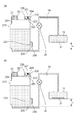
図13は、本実施形態に係るインク供給系を示す模式図である。インクタンク215には、大気連通口223が設けられ、その外側には大気連通口223を覆うように気液分離膜200が設けられている。気液分離膜200は、気体である空気は透過させるが、液体であるインクは透過させない。すなわち、印刷動作等によってインクが吐出されると、消費されたインク量分の空気が大気連通口223から気液交換部232を通ってインクタンク215内に流入する。ここで、インクタンク15の気液交換部232は、記録ヘッド13のインク吐出口31よりも高さ方向においてH低い位置に設けられている。そのため、高さH分の水頭差の負圧がインク吐出口31にかかる構成となっている。
FIG. 13 is a schematic diagram showing an ink supply system according to the present embodiment. The
また、インクタンク215の上部には圧力調整部201が設けられている。圧力調整部201は、回動中心206を中心に回動可能に支持され、開口部205を開閉可能に構成された開閉レバー203と、開閉レバー203を開口部205側に押圧する圧力調整ばね202とによって構成される。圧力調整部201は、大気連通部204を通じて大気と連通している。図13(a)は、気圧変動や温度変化が少ないときの状態を示しており、開閉レバー203によって開口部205は封止されている。一方、図13(b)は気圧変動や温度変化があったときの状態を示している。気圧変動や温度変化によってインク収容部234内の空気が膨張して、インクタンク215の内部の圧力が所定値を超えた場合、圧力調整ばね202は収縮し、開閉レバー203は上方に回動する。これによって、開口部205の封止が開放され、外部に圧力を逃がすことができる。本実施形態によれば、インクタンク215にバッファ室を設ける必要がないため、インク収容部234により多くのインクを収容する構成とすることが可能となる。
In addition, a
本実施形態では、タンクカバー(第1のカバー部材)42と連動して開閉するバルブユニット24は、インク供給路14のみに設け、大気連通路25には設けられていない。大気連通口223には気液分離膜200が設けられているため、インク注入時に注入されたインクが大気連通口223を通って外部に漏れ出ることはない。また、大気連通口223は、記録ヘッド13のインク吐出口31より高さ方向において下方の位置に設けられているため、気圧変動や温度変化によってインクの液面が大気連通口223の位置まで上昇したとしても記録ヘッド13が加圧されることはない。さらに、バルブユニット24が閉塞するチューブはインク供給路14のチューブのみとなっているため、ユーザーがタンクカバー42を操作する際に必要な力を軽減することができる。
In the present embodiment, the
以上、本実施形態によれば、インク注入時には確実にバルブを閉塞することができ、印刷動作時には記録ヘッド内を適正な負圧に保つことができる。 As described above, according to this embodiment, the valve can be reliably closed at the time of ink injection, and the inside of the recording head can be maintained at an appropriate negative pressure during the printing operation.
(第4実施形態)
次に、本発明の第4実施形態について図面を参照しながら詳細に説明する。なお、上記実施形態と同様の構成についてはその説明を省略する。
(Fourth embodiment)
Next, a fourth embodiment of the present invention will be described in detail with reference to the drawings. The description of the same configuration as that in the above embodiment is omitted.
図14は、本実施形態に係るインクジェット記録装置を示す概略図である。本実施形態では、インクジェット記録装置311の記録ヘッド13へのアクセスはアクセスカバー(第1のカバー部材)341を開くことにより可能となる。本実施形態では、タンクカバー42を設けず、アクセスカバー341をバルブユニット24の操作部とする構成としている。すなわち、アクセスカバー341の開閉操作と連動してバルブユニットが開閉する。アクセスカバー341には、図14中の左側に配置されたブラック側バルブユニットと右側に配置されたカラー側バルブユニットとのそれぞれに対向する位置において、突起部301が設けられている。
FIG. 14 is a schematic view showing an ink jet recording apparatus according to this embodiment. In the present embodiment, the access to the
図15は、バルブユニットの閉塞操作時の内部を示す模式図であり、カラー側バルブユニットを図14中のD方向から見た模式図である。図15(a)は、バルブが閉塞された状態を示している。カム部材84と一体に形成されたレバー部384に取り付けられた引張りばね310は、一端が装置本体に固定されている。引張りばね310は、カム部材84を図15中の反時計回りに引張り、チューブ81を閉塞させる位置まで回動させる。アクセスカバー341を閉じると、図15(a)に示すように、突起部301がレバー部384に当接する。図15(b)は、アクセスカバー341が閉じられた状態を示している。突起部301に押されたレバー部384は図15中の時計回りに回動し、チューブ81は開放された位置で停止する。
FIG. 15 is a schematic view showing the inside of the valve unit during the closing operation, and is a schematic view of the color side valve unit as viewed from the direction D in FIG. FIG. 15A shows a state where the valve is closed. One end of the
以上説明したように、アクセスカバー341が開いた状態ではバルブは閉塞されているため、インク注入時には確実にバルブを閉塞することができる。一方、アクセスカバー341が閉じた状態では確実にチューブ81を開放することができる。
As described above, since the valve is closed when the
また、本実施形態では、アクセスカバー341の開閉を検知可能な不図示のセンサを有し、アクセスカバー341が閉じた状態であると検知された場合に印刷動作を行うことできる構成としている。よって、バルブが開放されていない状態で印刷動作を実施して記録ヘッド13内にインクが供給されないという事態を防止することができる。
In the present embodiment, a sensor (not shown) that can detect opening / closing of the
11 インクジェット記録装置
13 記録ヘッド
15 インクタンク
24 バルブユニット
42 タンクカバー
11
Claims (12)
装置本体に設けられ、前記記録ヘッドへ供給されるインクを注入するための注入部を有し、インクを収容するインクタンクと、
前記注入部を覆う第1の位置と、前記注入部を開放する第2の位置とに移動可能な第1のカバー部材と、
前記インクタンクから前記記録ヘッドへインクを供給するためのインク供給路と、
前記インクタンクの内部を大気と連通させるための大気連通路と、を備えるインクジェット記録装置であって、
前記第1のカバー部材が前記第1の位置から前記第2の位置に移動したときに前記インク供給路および前記大気連通路を閉塞する閉状態と、前記第1のカバー部材が前記第2の位置から前記第1の位置に移動したときに前記インク供給路および前記大気連通路を開放する開状態と、に切り替わる切替部を備えることを特徴とするインクジェット記録装置。A recording head for recording an image by discharging ink;
An ink tank provided in the apparatus main body, having an injection portion for injecting ink to be supplied to the recording head, and containing ink;
A first cover member movable to a first position covering the injection portion and a second position opening the injection portion;
An ink supply path for supplying ink from the ink tank to the recording head;
An ink jet recording apparatus comprising: an atmosphere communication path for communicating the inside of the ink tank with the atmosphere;
A closed state in which the ink supply path and the atmosphere communication path are closed when the first cover member is moved from the first position to the second position; and the first cover member is the second cover An ink jet recording apparatus comprising: a switching unit that switches to an open state in which the ink supply path and the atmosphere communication path are opened when the position is moved from a position to the first position.
前記第1のカバー部材は、前記キャップが前記注入部を封止していないときは、前記キャップと当接することによって前記第2の位置から前記第1の位置への移動が抑制されることを特徴とする請求項1または2に記載のインクジェット記録装置。A cap for sealing the injection part;
When the cap does not seal the injection portion, the first cover member is prevented from moving from the second position to the first position by contacting the cap. an ink jet recording apparatus according to claim 1 or 2, characterized.
前記切替部は、前記第1のカバー部材の移動に応じて回動するカム部材と、前記カム部材と摺擦して変位することで前記チューブを閉塞可能な変位部材と、を有することを特徴とする請求項1から3のいずれか1項に記載のインクジェット記録装置。The ink supply path and the atmosphere communication path are configured by tubes,
The switching unit includes a cam member which rotates in response to movement of the first cover member, to have a displacement of a member which can close the tube by displacement rubs with said cam member the ink-jet recording apparatus according to any one of claims 1, wherein 3.
装置本体に設けられ、前記記録ヘッドへ供給されるインクを注入するための注入部を有し、インクを収容するインクタンクと、
前記注入部を封止するためのキャップと、
前記注入部を覆う第1の位置と、前記注入部を開放する第2の位置とに移動可能な第1のカバー部材と、
前記インクタンクから前記記録ヘッドへインクを供給するためのインク供給路と、
前記第1のカバー部材が前記第1の位置から前記第2の位置に移動したときに前記インク供給路を閉塞する閉状態と、前記第1のカバー部材が前記第2の位置から前記第1の位置に移動したときに前記インク供給路を開放する開状態と、に切り替わる切替部と、を備えるインクジェット記録装置であって、
前記第1のカバー部材は、前記キャップが前記注入部を封止していないときは、前記キャップと当接することによって前記第2の位置から前記第1の位置への移動が抑制されることを特徴とするインクジェット記録装置。A recording head for recording an image by discharging ink;
An ink tank provided in the apparatus main body, having an injection portion for injecting ink to be supplied to the recording head, and containing ink;
A cap for sealing the injection part;
A first cover member movable to a first position covering the injection portion and a second position opening the injection portion;
An ink supply path for supplying ink from the ink tank to the recording head;
A closed state in which the ink supply path is closed when the first cover member moves from the first position to the second position; and the first cover member moves from the second position to the first position. An open state that opens the ink supply path when moved to the position, and a switching unit that switches to an inkjet recording apparatus,
When the cap does not seal the injection portion, the first cover member is prevented from moving from the second position to the first position by contacting the cap. An ink jet recording apparatus.
前記切替部は、前記開状態のとき前記大気連通路を開放し、前記閉状態のとき前記大気連通路を閉塞することを特徴とする請求項5または6に記載のインクジェット記録装置。An atmosphere communication path for communicating the inside of the ink tank with the atmosphere;
The inkjet recording apparatus according to claim 5 , wherein the switching unit opens the atmosphere communication path when the switch is in the open state, and closes the atmosphere communication path when the switch is in the closed state.
前記切替部は、前記第1のカバー部材の移動に応じて回動するカム部材と、前記カム部材と摺擦して変位することで前記チューブを閉塞可能な変位部材と、を有することを特徴とする請求項7に記載のインクジェット記録装置。The ink supply path and the atmosphere communication path are configured by tubes,
The switching unit includes a cam member which rotates in response to movement of the first cover member, to have a displacement of a member which can close the tube by displacement rubs with said cam member 8. The ink jet recording apparatus according to claim 7 , wherein
前記第2のカバー部材が閉じた状態では前記第1のカバー部材を操作することができず、前記第2のカバー部材が開いた状態では前記第1のカバー部材を操作することができることを特徴とする請求項1から8のいずれか1項に記載のインクジェット記録装置。A second cover member pivotally supported by the apparatus main body so as to be opened and closed;
The first cover member cannot be operated when the second cover member is closed, and the first cover member can be operated when the second cover member is open. An ink jet recording apparatus according to any one of claims 1 to 8 .
前記検知手段によって前記第2のカバー部材が閉じた状態であると検知された場合は記録動作を行うことができ、前記第2のカバー部材が開いた状態であると検知された場合は記録動作を行うことができないことを特徴とする請求項9に記載のインクジェット記録装置。A detection means capable of detecting opening and closing of the second cover member;
When the detection means detects that the second cover member is in a closed state, a recording operation can be performed, and when it is detected that the second cover member is in an open state, a recording operation is performed. The ink jet recording apparatus according to claim 9 , wherein the ink jet recording apparatus cannot perform the operation.
Priority Applications (8)
| Application Number | Priority Date | Filing Date | Title |
|---|---|---|---|
| JP2015214967A JP6452594B2 (en) | 2015-10-30 | 2015-10-30 | Inkjet recording device |
| CN201610922678.4A CN106626786B (en) | 2015-10-30 | 2016-10-25 | Ink-jet recording apparatus |
| CN201811155205.1A CN109130521B (en) | 2015-10-30 | 2016-10-25 | Ink jet recording apparatus |
| US15/335,277 US10131154B2 (en) | 2015-10-30 | 2016-10-26 | Ink jet recording apparatus |
| EP16196454.9A EP3162573B1 (en) | 2015-10-30 | 2016-10-28 | Ink jet recording apparatus |
| EP19201322.5A EP3623159A1 (en) | 2015-10-30 | 2016-10-28 | Ink jet recording apparatus |
| KR1020160141567A KR102098677B1 (en) | 2015-10-30 | 2016-10-28 | Ink jet recording apparatus |
| US16/155,611 US10625514B2 (en) | 2015-10-30 | 2018-10-09 | Ink jet recording apparatus |
Applications Claiming Priority (1)
| Application Number | Priority Date | Filing Date | Title |
|---|---|---|---|
| JP2015214967A JP6452594B2 (en) | 2015-10-30 | 2015-10-30 | Inkjet recording device |
Related Child Applications (1)
| Application Number | Title | Priority Date | Filing Date |
|---|---|---|---|
| JP2018232912A Division JP6605115B2 (en) | 2018-12-12 | 2018-12-12 | Inkjet recording device |
Publications (3)
| Publication Number | Publication Date |
|---|---|
| JP2017081121A JP2017081121A (en) | 2017-05-18 |
| JP2017081121A5 JP2017081121A5 (en) | 2018-08-30 |
| JP6452594B2 true JP6452594B2 (en) | 2019-01-16 |
Family
ID=57211403
Family Applications (1)
| Application Number | Title | Priority Date | Filing Date |
|---|---|---|---|
| JP2015214967A Active JP6452594B2 (en) | 2015-10-30 | 2015-10-30 | Inkjet recording device |
Country Status (5)
| Country | Link |
|---|---|
| US (2) | US10131154B2 (en) |
| EP (2) | EP3623159A1 (en) |
| JP (1) | JP6452594B2 (en) |
| KR (1) | KR102098677B1 (en) |
| CN (2) | CN106626786B (en) |
Families Citing this family (20)
| Publication number | Priority date | Publication date | Assignee | Title |
|---|---|---|---|---|
| JP6794783B2 (en) * | 2016-11-04 | 2020-12-02 | セイコーエプソン株式会社 | Liquid injection device |
| JP2018140549A (en) * | 2017-02-28 | 2018-09-13 | セイコーエプソン株式会社 | printer |
| JP6759127B2 (en) * | 2017-02-28 | 2020-09-23 | キヤノン株式会社 | Inkjet recording device |
| JP2018171739A (en) | 2017-03-31 | 2018-11-08 | ブラザー工業株式会社 | Ink jet recording device |
| US11141983B2 (en) * | 2017-08-07 | 2021-10-12 | Hewlett-Packard Development Company, L.P. | Print fluid tank |
| CN109677124B (en) * | 2017-10-19 | 2021-08-20 | 鸿富锦精密工业(深圳)有限公司 | Ink path switching device and printing equipment |
| JP7077866B2 (en) | 2018-08-27 | 2022-05-31 | セイコーエプソン株式会社 | Liquid sprayer |
| JP7191602B2 (en) | 2018-09-10 | 2022-12-19 | キヤノン株式会社 | Liquid ejector |
| US11027551B2 (en) | 2019-01-17 | 2021-06-08 | Brother Kogyo Kabushiki Kaisha | System including a reservoir configured to store liquid and a tank to which the reservoir can be connected |
| JP7352127B2 (en) | 2019-01-17 | 2023-09-28 | ブラザー工業株式会社 | system |
| JP7259339B2 (en) * | 2019-01-17 | 2023-04-18 | ブラザー工業株式会社 | system |
| JP7251207B2 (en) | 2019-02-25 | 2023-04-04 | セイコーエプソン株式会社 | Liquid ejector |
| JP7287049B2 (en) * | 2019-03-27 | 2023-06-06 | ブラザー工業株式会社 | liquid consumption device |
| JP7257856B2 (en) * | 2019-04-05 | 2023-04-14 | キヤノン株式会社 | recording device |
| JP7377003B2 (en) * | 2019-04-05 | 2023-11-09 | キヤノン株式会社 | Liquid discharge device and control method |
| JP7367355B2 (en) * | 2019-06-26 | 2023-10-24 | セイコーエプソン株式会社 | recording device |
| JP2021187001A (en) * | 2020-05-27 | 2021-12-13 | セイコーエプソン株式会社 | Liquid jet device |
| JP2022123635A (en) * | 2021-02-12 | 2022-08-24 | キヤノン株式会社 | Liquid discharge device |
| JP2022123202A (en) * | 2021-02-12 | 2022-08-24 | キヤノン株式会社 | recording device |
| JP2023017622A (en) * | 2021-07-26 | 2023-02-07 | ブラザー工業株式会社 | Liquid discharging device and liquid storage container |
Family Cites Families (21)
| Publication number | Priority date | Publication date | Assignee | Title |
|---|---|---|---|---|
| JP2000094706A (en) * | 1998-09-17 | 2000-04-04 | Canon Inc | Ink jet recorder |
| JP2001010078A (en) * | 1999-04-27 | 2001-01-16 | Canon Inc | Ink tank, holder with the ink tank mounted, ink-jet recording apparatus provided with the holder, and method for mounting ink tank to holder |
| JP4524860B2 (en) * | 2000-05-30 | 2010-08-18 | 船井電機株式会社 | Inkjet device |
| JP2002301848A (en) * | 2001-04-04 | 2002-10-15 | Funai Electric Co Ltd | Ink-jet printer |
| JP4513337B2 (en) * | 2004-01-23 | 2010-07-28 | セイコーエプソン株式会社 | ink cartridge |
| JP2007021971A (en) * | 2005-07-20 | 2007-02-01 | Seiko Epson Corp | Liquid jetting device |
| JP2007106019A (en) * | 2005-10-14 | 2007-04-26 | Seiko Epson Corp | Inkjet recording device |
| JP4579813B2 (en) * | 2005-11-24 | 2010-11-10 | キヤノン株式会社 | Liquid jet recording device |
| JP4605394B2 (en) * | 2006-03-31 | 2011-01-05 | ブラザー工業株式会社 | Protection device for ink cartridge storage device |
| JP2008173871A (en) * | 2007-01-19 | 2008-07-31 | Seiko Epson Corp | Fluid feeding apparatus and fluid jetting apparatus using it |
| KR20080069388A (en) * | 2007-01-23 | 2008-07-28 | 삼성전자주식회사 | An ink supplying/sealing apparatus and image forming apparatus having the same |
| JP2008265350A (en) * | 2008-06-27 | 2008-11-06 | Seiko Epson Corp | Ink-jet printer |
| JP5163344B2 (en) * | 2008-07-30 | 2013-03-13 | セイコーエプソン株式会社 | Droplet discharge device and head cleaning control method for droplet discharge device |
| JP6020804B2 (en) * | 2012-08-10 | 2016-11-02 | セイコーエプソン株式会社 | Recording device |
| JP6083167B2 (en) * | 2012-09-14 | 2017-02-22 | セイコーエプソン株式会社 | Liquid container and liquid consumption apparatus |
| US9090081B2 (en) * | 2012-09-21 | 2015-07-28 | Cal-Comp Electronics & Communications Company Limited | Ink supply system and multifunctional printer |
| TWI504520B (en) * | 2012-12-20 | 2015-10-21 | Cal Comp Electronics & Comm Co | Ink supply system and media recording device |
| TWI483853B (en) | 2012-09-21 | 2015-05-11 | Cal Comp Electronics & Comm Co | Multifunctional printer |
| JP2014079910A (en) | 2012-10-15 | 2014-05-08 | Seiko Epson Corp | Recording device |
| JP2014100842A (en) * | 2012-11-19 | 2014-06-05 | Ricoh Co Ltd | Image formation apparatus |
| JP2015112847A (en) * | 2013-12-13 | 2015-06-22 | 株式会社リコー | Liquid supply device and image formation device including the same |
-
2015
- 2015-10-30 JP JP2015214967A patent/JP6452594B2/en active Active
-
2016
- 2016-10-25 CN CN201610922678.4A patent/CN106626786B/en active Active
- 2016-10-25 CN CN201811155205.1A patent/CN109130521B/en active Active
- 2016-10-26 US US15/335,277 patent/US10131154B2/en active Active
- 2016-10-28 EP EP19201322.5A patent/EP3623159A1/en active Pending
- 2016-10-28 KR KR1020160141567A patent/KR102098677B1/en active IP Right Grant
- 2016-10-28 EP EP16196454.9A patent/EP3162573B1/en active Active
-
2018
- 2018-10-09 US US16/155,611 patent/US10625514B2/en active Active
Also Published As
| Publication number | Publication date |
|---|---|
| KR20170051317A (en) | 2017-05-11 |
| EP3162573A1 (en) | 2017-05-03 |
| US10131154B2 (en) | 2018-11-20 |
| JP2017081121A (en) | 2017-05-18 |
| US20170120617A1 (en) | 2017-05-04 |
| US10625514B2 (en) | 2020-04-21 |
| US20190039383A1 (en) | 2019-02-07 |
| CN109130521A (en) | 2019-01-04 |
| CN106626786A (en) | 2017-05-10 |
| CN106626786B (en) | 2018-11-09 |
| KR102098677B1 (en) | 2020-04-08 |
| EP3162573B1 (en) | 2019-12-11 |
| CN109130521B (en) | 2020-08-11 |
| EP3623159A1 (en) | 2020-03-18 |
Similar Documents
| Publication | Publication Date | Title |
|---|---|---|
| JP6452594B2 (en) | Inkjet recording device | |
| JP6667260B2 (en) | Ink jet recording device | |
| JP6584450B2 (en) | Inkjet recording device | |
| JP6556021B2 (en) | Liquid ejection device and method for replacing the liquid ejection head | |
| US10500869B2 (en) | Ink jet recording apparatus | |
| JP6605115B2 (en) | Inkjet recording device | |
| JP2023099716A (en) | Liquid consuming device | |
| JP5630323B2 (en) | Shipment method of image forming apparatus | |
| US20220258487A1 (en) | Printing apparatus | |
| US11787184B2 (en) | Recording apparatus | |
| JP2017081125A (en) | Ink jet recording apparatus | |
| US10967643B2 (en) | Liquid ejecting apparatus | |
| US20220410604A1 (en) | Printing apparatus and control method | |
| US20220258485A1 (en) | Printing apparatus | |
| US20220258477A1 (en) | Liquid discharge apparatus | |
| JP2019196014A (en) | Inkjet recording device | |
| JP2020051600A (en) | Channel control device and ink jet recording device |
Legal Events
| Date | Code | Title | Description |
|---|---|---|---|
| A621 | Written request for application examination |
Free format text: JAPANESE INTERMEDIATE CODE: A621 Effective date: 20180511 |
|
| A521 | Written amendment |
Free format text: JAPANESE INTERMEDIATE CODE: A523 Effective date: 20180718 |
|
| A871 | Explanation of circumstances concerning accelerated examination |
Free format text: JAPANESE INTERMEDIATE CODE: A871 Effective date: 20180718 |
|
| A975 | Report on accelerated examination |
Free format text: JAPANESE INTERMEDIATE CODE: A971005 Effective date: 20180803 |
|
| A131 | Notification of reasons for refusal |
Free format text: JAPANESE INTERMEDIATE CODE: A131 Effective date: 20180821 |
|
| A521 | Written amendment |
Free format text: JAPANESE INTERMEDIATE CODE: A523 Effective date: 20181018 |
|
| TRDD | Decision of grant or rejection written | ||
| A01 | Written decision to grant a patent or to grant a registration (utility model) |
Free format text: JAPANESE INTERMEDIATE CODE: A01 Effective date: 20181113 |
|
| A61 | First payment of annual fees (during grant procedure) |
Free format text: JAPANESE INTERMEDIATE CODE: A61 Effective date: 20181211 |
|
| R151 | Written notification of patent or utility model registration |
Ref document number: 6452594 Country of ref document: JP Free format text: JAPANESE INTERMEDIATE CODE: R151 |