JP6452452B2 - Image forming method - Google Patents
Image forming method Download PDFInfo
- Publication number
- JP6452452B2 JP6452452B2 JP2015001208A JP2015001208A JP6452452B2 JP 6452452 B2 JP6452452 B2 JP 6452452B2 JP 2015001208 A JP2015001208 A JP 2015001208A JP 2015001208 A JP2015001208 A JP 2015001208A JP 6452452 B2 JP6452452 B2 JP 6452452B2
- Authority
- JP
- Japan
- Prior art keywords
- toner
- mass
- image
- undercoat layer
- resin
- Prior art date
- Legal status (The legal status is an assumption and is not a legal conclusion. Google has not performed a legal analysis and makes no representation as to the accuracy of the status listed.)
- Active
Links
Images

Description
本発明は、電子写真,静電潜像を顕像化するための画像形成方法に関する。また、該画像形成方法に用いられるプロセスカートリッジに関する。 The present invention relates to an electrophotographic image forming method for visualizing an electrostatic latent image. The present invention also relates to a process cartridge used in the image forming method.
一般的な電子写真法は、光導電性物質を利用し、種々の手段により像担持体上に静電潜像を形成し、次いで該潜像をトナーを用いて現像し、必要に応じて紙等の転写材にトナー画像を転写する。その後、加熱、加圧、加熱加圧或いは溶剤蒸気などにより定着し、被写物を得、像担持体上に転写されずに残ったトナーは種々の方法でクリーニングされ、上記工程が繰り返される手法である。 In general electrophotography, a photoconductive substance is used to form an electrostatic latent image on an image carrier by various means, and then the latent image is developed with toner, and paper is used as necessary. The toner image is transferred to a transfer material such as. Thereafter, fixing is performed by heating, pressurizing, heating / pressurizing, or solvent vapor to obtain an object, and the toner remaining without being transferred onto the image carrier is cleaned by various methods, and the above steps are repeated. It is.
近年、この電子写真装置は、小型化、高速化、及び高耐久性が厳しく追及されてきている。また、この電子写真装置は、単なるテキスト文字を出力するための装置というだけでなく、例えば、グラフィックデザイン等の高細密画像の出力用に用いられつつある。そのため、画質としてより高精細,高画質が求められており、従来以上に、濃度変動や画像欠陥に対する改善要求が厳しくなっている。 In recent years, this electrophotographic apparatus has been strictly pursued for miniaturization, high speed, and high durability. In addition, this electrophotographic apparatus is not only a device for outputting text characters but also being used for outputting high-definition images such as graphic designs. Therefore, higher definition and higher image quality are required as image quality, and demands for improvement with respect to density fluctuations and image defects are becoming stricter than ever.
そのため、このような用途で用いられる電子写真装置は、環境や印字枚数、さらには、同一画像内でも、画像の品質が変わらないことが重要となる。 For this reason, it is important for the electrophotographic apparatus used in such applications that the quality of the image does not change even within the same image.
また、非画像部へのトナーの飛び散りは、上述した用途で使用される場合、画像欠陥として扱われるため、特に注意を要する。一般的にライン画像を出力した場合、ライン部と境界になる白地部周辺でトナー飛び散りが発生しやすい。これは、像担持体(以下、感光体と記す)の暗減衰と密接な関連があると考えられている。 Further, the scattering of the toner to the non-image portion is treated as an image defect when used in the above-described application, and therefore requires special attention. In general, when a line image is output, toner scattering is likely to occur around a white background portion that is a boundary with the line portion. This is considered to be closely related to the dark decay of an image carrier (hereinafter referred to as a photoreceptor).
暗減衰とは、感光体の表面を帯電した際の表面電位が、暗所において、時間とともに低下(減衰)していく現象である。これは、現像工程から転写工程といった、極短時間でも発生する現象である。暗減衰が大きいと、表面電位が低下し、ライン画像端部のトナーは、画像上に保持できずに、一部境界の白地部に飛散し、画質を低下させる場合がある。 Dark decay is a phenomenon in which the surface potential when the surface of a photoreceptor is charged decreases (decays) with time in a dark place. This is a phenomenon that occurs even in a very short time, such as from the development process to the transfer process. If the dark decay is large, the surface potential is lowered, and the toner at the end of the line image may not be held on the image, but may be scattered on a white background part of the boundary, thereby reducing the image quality.
そのため、感光体としては、暗減衰が発生し難い構成に、トナーとしては、暗減衰が発生しても、白地部にトナーが飛散し難くする必要がある。 For this reason, it is necessary that the photosensitive member has a configuration in which dark attenuation does not easily occur, and that the toner has difficulty in scattering the toner on the white background even if dark attenuation occurs.
暗減衰は発生しても、白地部にトナーが飛散しないようにするためには、感光体とトナー間及び、トナー間の付着力が強く、電位変動の影響を受けにくくする必要がある。 Even if dark decay occurs, in order to prevent the toner from scattering on the white background, the adhesion between the photoconductor and the toner and between the toners must be strong and less susceptible to potential fluctuations.
また、長期間使用してもトナー母体粒子の中に外添剤が埋め込まれたりする、所謂「トナー劣化」が生じ難いことも必要である。トナー劣化が発生するということは、初期と長期使用後でトナーの表面状態が変化し、帯電状態も変化するため、長期間安定して高画質化を達成するためには、好ましくない状態である。 Further, it is also necessary that the so-called “toner degradation” in which an external additive is embedded in the toner base particles even when used for a long period of time hardly occurs. The occurrence of toner deterioration is not preferable in order to achieve high image quality stably for a long period of time because the surface state of the toner changes after the initial and long-term use and the charged state also changes. .
このように、付着力制御やトナー劣化抑制のためには、トナーの表面状態を制御する必要があり、その中でも外添剤の設計が重要となる。 As described above, in order to control adhesion force and suppress toner deterioration, it is necessary to control the surface state of the toner, and among them, the design of the external additive is important.
トナー劣化抑制という観点で、トナーに大粒径の外添剤を添加するという手段が用いられている。 From the viewpoint of suppressing toner deterioration, a means of adding an external additive having a large particle diameter to the toner is used.
例えば特許文献1では、外添剤として個数平均一次粒子径が60nm〜120nmであるケイ素元素を含む酸化物粒子を用いるトナーが提案されている。当該文献には、外添剤の埋没がなく、長期間の使用においてもかぶりによる画像不良の発生がない、高画質の画像を安定して得られるとの記載がある。しかしながら、暗減衰によるトナー画質の悪化に関しては、十分に議論がされておらず、上述したような高細密画像という観点に対しては、改良の余地が残る。 For example, Patent Document 1 proposes a toner using oxide particles containing silicon element having a number average primary particle diameter of 60 nm to 120 nm as an external additive. The document describes that a high-quality image can be stably obtained without burying external additives and without causing image defects due to fogging even when used for a long period of time. However, the toner image quality deterioration due to dark attenuation has not been sufficiently discussed, and there remains room for improvement from the viewpoint of the above-described high-definition image.
また特許文献2では、外添剤として金属酸化物とポリマーを含む金属酸化物−ポリマー複合体粒子を含むトナーが提案されている。当該文献によれば、前記外添剤を用いることで、トナー粒子間でスペーサーとして役立つと共に、外添剤のトナーからの離脱を抑制出来ると記載されている。しかしながら、当該文献では、高画質化に関しては、なんら記載はなく、高細密画像の出力用という観点では未だ改良すべき点は多い。 Patent Document 2 proposes a toner containing metal oxide-polymer composite particles containing a metal oxide and a polymer as external additives. According to this document, it is described that the use of the external additive serves as a spacer between the toner particles and can prevent the external additive from being detached from the toner. However, in this document, there is no description about improving the image quality, and there are still many points to be improved from the viewpoint of output of high-definition images.
一方、感光体からも、高画質化を達成させるために種々の手法が提案されている。例えば、特許文献3では、電子受容性物質含有層を感光体内に設けることで、電気特性の変動が少なく且つ画質欠陥の発生を十分に抑制できる感光体の提案がされている。感光体にこのような層を含有させる事で、長期間使用による電荷の蓄積を抑制でき、その結果、繰り返し使用時における電気特性や画質の安定性向上には一定の効果は発現できる。しかしながら、当該文献では、感光体と電荷の授受をすべきトナーの特性に関しては、なんら記載はなく、高細密画像の出力用という観点では未だ改良すべき点は多い。
On the other hand, various methods have been proposed from the photoconductor to achieve high image quality. For example,
本発明の目的は、トナー飛び散りや画像欠陥のない、長期に渡り安定的に高画質画像を得る事が出来る画像形成方法及びプロセスカートリッジを提供する事である。 An object of the present invention is to provide an image forming method and a process cartridge capable of stably obtaining a high-quality image over a long period of time without toner scattering and image defects.
本発明は、像担持体を帯電させる帯電工程、該像担持体に静電潜像を形成する静電潜像形成工程、該静電潜像をトナーで現像し、トナー像を形成する現像工程、該トナー像を中間転写体を介して、または介さずに転写材に転写する転写工程、を有する画像形成方法において、
該トナーは結着樹脂及び着色剤を含有するトナー粒子と、外添剤Aを有するトナーであり、
該外添剤Aは、有機無機複合微粒子であり、該有機無機複合微粒子の表面には、無機微粒子に由来する凸部が複数存在し、該有機無機複合微粒子の体積抵抗率が1.0×10 10 Ω・cm以上であり、
該外添剤Aの個数平均粒径(D1)が70nm以上500nm以下であり、且つ該外添剤Aをメタノール中に分散させた時の該外添剤Aのゼータ電位ζ(A)が−50mV以上−15mV以下であり、
該像担持体は、支持体、該支持体上に形成された下引き層、該下引き層の上に形成された感光層を有し、
該下引き層は、体積抵抗率が1×10¹¹Ω・cm以上1×10¹⁶Ω・cm以下であり、かつ重合性官能基を有する有機電子輸送性化合物と架橋剤とを含有する組成物の重合物を含有する層であることを特徴とする画像形成方法に関する。
The present invention relates to a charging step for charging an image carrier, an electrostatic latent image forming step for forming an electrostatic latent image on the image carrier, and a developing step for developing the electrostatic latent image with toner to form a toner image. A transfer step of transferring the toner image to a transfer material with or without an intermediate transfer member,
The toner is a toner having toner particles containing a binder resin and a colorant and an external additive A,
The external additive A is organic / inorganic composite fine particles, and there are a plurality of convex portions derived from the inorganic fine particles on the surface of the organic / inorganic composite fine particles, and the volume resistivity of the organic / inorganic composite fine particles is 1.0 ×. 10 10 Ω · cm or more,
The number average particle diameter (D1) of the external additive A is 70 nm to 500 nm, and the zeta potential ζ (A) of the external additive A when the external additive A is dispersed in methanol is − 50 mV or more and −15 mV or less,
The image carrier has a support, an undercoat layer formed on the support, a photosensitive layer formed on the undercoat layer,
The undercoat layer has a volume resistivity of 1 × 10 11 Ω · cm to 1 × 10 16 Ω · cm, and contains an organic electron transporting compound having a polymerizable functional group and a crosslinking agent. It is related with the image forming method characterized by being a layer containing polymer of these.
本発明によれば、印字画像周辺のトナー飛び散りや画像欠陥を抑えた高画質画像を長期に渡り安定的に出力出来る画像形成方法及びプロセスカートリッジを提供することが可能となる。 According to the present invention, it is possible to provide an image forming method and a process cartridge that can stably output a high-quality image with suppressed toner scattering and image defects around a printed image over a long period of time.
本発明の画像形成方法について説明する。 The image forming method of the present invention will be described.
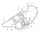
図1に本発明の画像形成方法を適用することのできる画像形成装置を、図2に画像形成装置の本体に着脱可能なプロセスカートリッジの概略図を示す。図1は中間転写体を介さずにトナー像を転写材に転写する例を示すが、本発明は中間転写体を備えた画像形成装置にも適用できる。 FIG. 1 is a schematic view of an image forming apparatus to which the image forming method of the present invention can be applied, and FIG. 2 is a schematic view of a process cartridge that can be attached to and detached from the main body of the image forming apparatus. FIG. 1 shows an example in which a toner image is transferred to a transfer material without using an intermediate transfer member, but the present invention can also be applied to an image forming apparatus provided with an intermediate transfer member.
本実施例の画像形成装置14は、電子写真プロセスを利用したレーザービームプリンタである。7は像担持体としての回転ドラム型の感光体であり、所定の周速度にて回転駆動される。
The
感光体7は回転する過程において帯電ローラ8により所定の極性、所定の電位、に一様に帯電処理される。1は露光手段としてのレーザービームスキャナである。スキャナ1は、不図示のイメージスキャナやコンピュータ等の外部機器から入力される画像情報に応じて変調したレーザー光を出力して、感光体7の帯電処理した面を走査露光する。この走査露光により感光体7表面の電荷が除電され感光体7の表面に画像情報に応じた静電潜像が形成される。Bはプロセスカートリッジであり、現像ローラ9aから感光体7表面にトナーが供給されて静電潜像がトナー像として現像される。3aは、転写材2が積載して収納される給紙カセットである。給紙開始信号に基づいてピックアップローラ3bが駆動されて給紙カセット3a内の転写材2が一枚ずつ分離して給紙される。その転写材2は、搬送手段3を介して、感光体7と転写ローラ4とで形成された転写部位に所定のタイミングで導入される。すなわち、感光体7上のトナー像の先端部が転写部位に到達するタイミングで、転写材2の先端部が転写部位に到達するように搬送手段3で転写材2の搬送が制御される。転写部位に導入された転写材2は、この転写部位で搬送され、その間、転写ローラ4は不図示の転写バイアス印加電源によって転写バイアス電圧が印加される。転写ローラ4はトナーと逆極性の転写バイアス電圧が印加されることで転写部位において感光体7の表面側のトナー像が転写材2の表面に転写される。転写部位においてトナー像が転写された転写材2は感光体7の表面から分離されて、定着手段5で定着処理される。
The
一方、転写材が感光体7から分離した後の感光体7の表面はクリーニング手段10でクリーニングされ、繰り返し画像形成動作に供される。定着手段5を通った転写材2は、排紙口から排紙トレイ6上に排出される。
On the other hand, the surface of the
なお後述する暗減衰は、感光体7表面にトナーが現像されてから、転写部位においてトナー像が転写材2に転写されるまでの間に、感光体7において生じる現象を示している。
The dark decay described later indicates a phenomenon that occurs in the
本発明者等は、高画質化が求められる電子写真装置において、長期に渡り、高画質画像を得るためには、トナー及び感光体両面からアプローチする必要があると考えた。 The present inventors have considered that it is necessary to approach from both the toner and the photoreceptor in order to obtain a high-quality image for a long time in an electrophotographic apparatus that requires high image quality.
本発明の一つとして、トナー粒子表面に、個数平均粒径(DA)が70nm以上500nm以下であり、且つメタノール中に分散させた時のゼータ電位ζが−50mV以上−15mV以下である外添剤を添加したトナーを用いる必要がある。 As one aspect of the present invention, the number average particle diameter (DA) is 70 nm to 500 nm on the toner particle surface, and the zeta potential ζ when dispersed in methanol is -50 mV to -15 mV. It is necessary to use toner added with an agent.
トナー劣化を抑制させる為の手段としては、従来より大粒径の外添剤を添加することは知られていた。しかしながら、こういった外添剤は、トナー間の物理的な接触を低減することに主眼が置かれているために、暗減衰等の電位の変動に対する対応という観点では、それほど重要視されていなかった。そのため、従来のテキスト文字を出力する装置においては、大きな問題とはならなかったが、高精細画像を出力する観点からは問題となりうる場合がある。 As a means for suppressing toner deterioration, it has been conventionally known to add an external additive having a large particle diameter. However, since these external additives are focused on reducing physical contact between toners, they are not so important in terms of dealing with potential fluctuations such as dark decay. It was. Therefore, in a conventional device that outputs text characters, this has not been a big problem, but it may be a problem from the viewpoint of outputting a high-definition image.
こういった背景から、本発明者らは、外添剤の物理的特性と電気的特性を鋭意検討した結果、個数平均粒径(DA)が70nm以上500nm以下であり、且つメタノール中に分散させた時のゼータ電位ζ(A)が−50mV以上−15mV以下である外添剤を添加することで、電位変動に対しても一定の効果がある外添剤を見出した。 Against this background, the present inventors have intensively studied the physical and electrical characteristics of the external additive, and as a result, the number average particle diameter (DA) is 70 nm or more and 500 nm or less and is dispersed in methanol. By adding an external additive having a zeta potential ζ (A) of −50 mV to −15 mV, an external additive having a certain effect on potential fluctuation was found.
ゼータ電位とは、溶液中の微小粒子の周囲に形成されるイオン固定層とイオン拡散層とよばれる電気二重層中の、液体流動が起こり始める「滑り面」の電位として定義される。 The zeta potential is defined as the potential of a “sliding surface” at which liquid flow starts to occur in an electric double layer called an ion fixed layer and an ion diffusion layer formed around microparticles in a solution.
微小粒子の表面特性により、このゼータ電位の絶対値は正(正帯電性)や負(負帯電性)の値を示す。また、この絶対値が大きいほど微小粒子表面の電荷が大きいことを示す。 Depending on the surface characteristics of the microparticles, the absolute value of the zeta potential is positive (positive chargeability) or negative (negative chargeability). Moreover, it shows that the electric charge of the surface of a microparticle is so large that this absolute value is large.
そのため、トナー粒子表面に、ある粒子径で且つ特定のゼータ電位を有する外添剤を付着させる事で、この外添剤A起因の電荷層がトナー表面に形成され、トナー間の電位の安定化に寄与するものと考えられる。その結果、感光体上で、多少の電位変動が生じても、飛び散り等につながり難くなると思われる。 Therefore, by attaching an external additive having a specific particle size and a specific zeta potential to the toner particle surface, a charge layer due to the external additive A is formed on the toner surface, and the potential between the toners is stabilized. It is thought that it contributes to. As a result, even if some potential fluctuation occurs on the photosensitive member, it is considered that it is difficult to cause scattering.
よって、外添剤Aの個数平均粒径(DA)は70nm以上500nm以下、好ましくは85nm以上170nm以下であることが特徴である。 Accordingly, the number average particle diameter (DA) of the external additive A is 70 nm to 500 nm, preferably 85 nm to 170 nm.
この範囲に制御することで、トナー間の物理的な接触を低減でき、トナー劣化抑制に効果を発揮すると共に、上述したような、トナー表面に電荷層を形成しやすくなるものと考えられる。 By controlling within this range, it is considered that physical contact between toners can be reduced, and the toner deterioration can be effectively suppressed, and the charge layer can be easily formed on the toner surface as described above.
外添剤Aの個数平均粒径(DA)が70nm未満の場合は、トナー粒子表面から外添剤の突出が十分でなく、電荷層が十分に形成されない。また、トナー劣化も発生しやくすなるため、長期間の使用によって、ライン画像周辺の飛び散りが悪化しやくなる。一方、500nmよりも大きい場合は、トナーから離脱しやすくなり、離脱粒子起因の画像欠陥が発生しやすくなる。 When the number average particle diameter (DA) of the external additive A is less than 70 nm, the external additive does not sufficiently protrude from the toner particle surface, and the charge layer is not sufficiently formed. Further, since toner deterioration is likely to occur, scattering around the line image is likely to be deteriorated by long-term use. On the other hand, when it is larger than 500 nm, the toner is easily detached from the toner, and image defects due to the detached particles are likely to occur.
また、この外添剤Aのゼータ電位ζ(A)が−50mVよりも小さい場合は、トナー表面の電荷層の負帯電性が大きくなり過ぎ、トナー間の電気的な反発力が強くなってくる。そのため、潜像を忠実に再現できなくなり、ライン画像がやや太くなるような状況が発生し、ライン再現性が悪化する。一方、−15mVよりも大きい場合は、電荷層が十分に形成されないため、耐久初期から、飛び散りが悪化し、画質悪化につながる。 When the zeta potential ζ (A) of the external additive A is smaller than −50 mV, the negative chargeability of the charge layer on the toner surface becomes too large, and the electric repulsive force between the toners becomes strong. . For this reason, the latent image cannot be faithfully reproduced, and the situation in which the line image becomes slightly thick occurs, and the line reproducibility deteriorates. On the other hand, when the voltage is larger than −15 mV, the charge layer is not sufficiently formed.
また、該像担持体は、支持体、該支持体上に形成された下引き層、該下引き層上に形成された感光層を有し、該下引き層の体積抵抗率が1×10¹¹以上1×10¹⁶Ω・cm以下であり、かつ有機電子輸送性化合物を含有することも特徴である。 The image carrier has a support, an undercoat layer formed on the support, and a photosensitive layer formed on the undercoat layer, and the volume resistivity of the undercoat layer is 1 × 10. It is also characterized by containing an organic electron transporting compound that is 11 or more and 1 × 10 16 Ω · cm or less.
現在、プロセスカートリッジや電子写真装置に用いられる感光体としては、有機光導電性物質を含有する感光体が主流である。感光体は、一般的に、支持体および支持体上に形成された感光層を有する。そして、支持体側から感光層側への電荷注入を抑制し、黒ポチなどの画像欠陥の発生を抑えることを目的として、支持体と感光層との間に下引き層が設けられていることが多い。 At present, a photoreceptor containing an organic photoconductive substance is mainly used as a photoreceptor used in a process cartridge or an electrophotographic apparatus. The photoreceptor generally has a support and a photosensitive layer formed on the support. An undercoat layer may be provided between the support and the photosensitive layer for the purpose of suppressing charge injection from the support side to the photosensitive layer side and suppressing the occurrence of image defects such as black spots. Many.
近年、電荷発生物質は、より高い感度を有するものが用いられている。しかしながら、電荷発生物質が高感度化するのに伴い、電荷の発生量が多くなることにより電荷が下引き層、下引き層と感光層との界面で電荷が滞留しやすくなり、繰り返し使用により、その現象が顕著になる。 In recent years, charge generation materials having higher sensitivity have been used. However, as the charge generation material becomes highly sensitive, the amount of generated charge increases, so that the charge tends to stay at the interface between the undercoat layer and the undercoat layer and the photosensitive layer. The phenomenon becomes remarkable.
この下引き層の体積抵抗率が1×10¹¹Ω・cm以上1×10¹⁶Ω・cm以下であり、かつ有機電子輸送性化合物が含有することで、電荷の滞留を抑え、感光体の表面電位の低下(減衰)が抑えられる。また、有機電子輸送性化合物を含有することで、上述したトナー表面の電荷層を安定化でき、感光体とトナーとの付着性が向上し、非画像部へのトナー飛び散りをより抑制できるものと考えられる。 The volume resistivity of the undercoat layer is 1 × 10 11 Ω · cm or more and 1 × 10 16 Ω · cm or less, and the organic electron transport compound is contained, thereby suppressing charge retention and the surface of the photoreceptor. Potential decrease (decay) is suppressed. Further, by containing an organic electron transporting compound, the above-described charge layer on the toner surface can be stabilized, the adhesion between the photoreceptor and the toner can be improved, and toner scattering to the non-image area can be further suppressed. Conceivable.
該下引き層の体積抵抗率が1×10¹¹Ω・cm未満の場合には、表面電位の低下が発生しやすくなり、耐久初期のトナー飛び散りが悪化する。一方、1×10¹⁶Ω・cmよりも大きい場合は、露光後現像までに電子が十分に移動できないため、現像コントラストが十分に得られず、画像濃度が低下する。 When the volume resistivity of the undercoat layer is less than 1 × 10 11 Ω · cm, the surface potential tends to decrease, and toner scattering at the initial stage of durability deteriorates. On the other hand, if it is larger than 1 × 10 16 Ω · cm, electrons cannot sufficiently move before development after exposure, so that sufficient development contrast cannot be obtained and image density is lowered.
このように、特定の機能を有する外添剤を添加したトナーと、下引き層を制御した像担持体とを組み合わせることで、印字画像周辺のトナー飛び散りや画像欠陥を抑えた高画質画像を長期に渡り安定的に出力出来るのである。 In this way, by combining the toner added with an external additive having a specific function and the image carrier having a controlled undercoat layer, a high-quality image with reduced toner scattering and image defects around the printed image can be obtained for a long time. It is possible to output stably over the range.
また、本発明のトナーは、トナー粒子をメタノール中に分散させた時のトナー粒子のゼータ電位ζ(T)と、外添剤Aをメタノール中に分散させた時の外添剤Aのゼータ電位ζ(A)との差の絶対値|ζ(T)−ζ(A)|が5mV以上50mV以下、好ましくは5mV以上45mV以下であることが好ましい。 The toner of the present invention, the zeta potential of the toner particles when the toner particles dispersed in methanol zeta (T), the zeta potential of the external additive A when the external additive A was dispersed in methanol The absolute value | ζ (T) −ζ (A) | of the difference from ζ (A) is 5 mV to 50 mV, preferably 5 mV to 45 mV.
ゼータ電位の差が一定量有するトナー粒子と外添剤Aとを用いるということは、トナー粒子表面と外添剤Aとで、一定の電位差を有することを意味する。一般的にトナー粒子に外添剤を添加した場合、ファンデルワールス力のような分子間力、静電引力、液架橋力等が発生することが知られている。このように、トナー粒子と外添剤Aとに一定の引力を作用させることが出来るため、多少電位が変動しても、隣り合うトナー間で、トナー粒子とトナー粒子に付着している外添剤Aとの凝集力により、飛び散り等を抑制できる。 The use of toner particles having a constant zeta potential difference and external additive A means that the toner particle surface and external additive A have a constant potential difference. In general, it is known that when an external additive is added to toner particles, intermolecular force such as van der Waals force, electrostatic attraction, liquid cross-linking force and the like are generated. As described above, since a constant attractive force can be applied to the toner particles and the external additive A, even if the potential fluctuates slightly, the external additive adhered to the toner particles and the toner particles between adjacent toners. Due to the cohesive force with the agent A, scattering and the like can be suppressed.
また、本発明の外添剤Aは有機無機複合微粒子であり、該有機無機複合微粒子の表面には、無機微粒子に由来する凸部が複数存在し、該有機無機複合微粒子の体積抵抗率が1.0×10¹⁰Ω・cm以上であることが好ましい。 Further, the external additive A of the present invention is an organic-inorganic composite fine particle, and a plurality of convex portions derived from the inorganic fine particle are present on the surface of the organic-inorganic composite fine particle, and the volume resistivity of the organic-inorganic composite fine particle is 1 It is preferably 0.0 × 10 10 Ω · cm or more.
また、この有機無機複合微粒子は、倍率20万倍で測定したときの形状係数SF−2が103以上120以下であることが好ましい。微粒子表面に凸部を有する構造を取ることで、トナー粒子表面へのアンカリング効果が得られ易く、トナー粒子からの外添剤の離脱を抑制できる。また、凸部は、前記有機無機複合微粒子の無機微粒子に由来する凸部であることが好ましい。無機微粒子に由来する凸部があることで、アンカリング効果が促進される。 The organic-inorganic composite fine particles preferably have a shape factor SF-2 of 103 to 120 when measured at a magnification of 200,000 times. By adopting a structure having convex portions on the surface of the fine particles, an anchoring effect on the surface of the toner particles can be easily obtained, and detachment of the external additive from the toner particles can be suppressed. Moreover, it is preferable that a convex part is a convex part derived from the inorganic fine particle of the said organic inorganic composite fine particle. An anchoring effect is accelerated | stimulated because there exists a convex part derived from an inorganic fine particle.
なお有機無機複合微粒子の表面に無機微粒子が存在していれば良く、樹脂粒子内部における無機微粒子の有無は特に限定されない。なお、有機無機複合微粒子のSF−2値は、前記有機無機複合微粒子表面の無機微粒子存在比率で制御することが出来る。 Note that it is only necessary that the inorganic fine particles exist on the surface of the organic-inorganic composite fine particles, and the presence or absence of the inorganic fine particles inside the resin particles is not particularly limited. The SF-2 value of the organic / inorganic composite fine particles can be controlled by the inorganic fine particle existing ratio on the surface of the organic / inorganic composite fine particles.
例えば、無機微粒子としてシリカを用いる場合、表面シリカ存在比率は50%以上80%以下であることが好ましい。 For example, when silica is used as the inorganic fine particles, the surface silica existing ratio is preferably 50% or more and 80% or less.
さらに、有機無機複合微粒子の体積抵抗率が1.0×10¹⁰Ω・cm以上であることが、本発明のゼータ電位ζ(A)を制御する上で好ましい。 Furthermore, the volume resistivity of the organic / inorganic composite fine particles is preferably 1.0 × 10 10 Ω · cm or more in terms of controlling the zeta potential ζ (A) of the present invention.
また、本発明のトナーは、該トナー粒子100質量部に対して、0.5質量部以上3.0質量部以下の該有機無機複合微粒子を含有することが、トナー劣化を抑制する上で好ましい。 In addition, the toner of the present invention preferably contains 0.5 to 3.0 parts by mass of the organic-inorganic composite fine particles with respect to 100 parts by mass of the toner particles in order to suppress toner deterioration. .
本発明で用いられる有機無機複合微粒子としては、上記特性を有していれば、特に制限は無いが、例えば、WO 2013/063291の実施例の記載に従って製造することができる。 The organic-inorganic composite fine particles used in the present invention are not particularly limited as long as the organic-inorganic composite fine particles have the above-described characteristics. For example, the organic-inorganic composite fine particles can be produced according to the description in the examples of WO 2013/063291.
また、本発明で用いられる有機無機複合微粒子に用いられる材料として特に制限は無いが、ビニル系樹脂粒子に無機微粒子としてシリカ、酸化チタン、アルミナからなる群より選ばれる少なくとも1種の無機酸化物粒子を用いることが好ましく、シリカを用いることがより好ましい。 Further, the material used for the organic-inorganic composite fine particles used in the present invention is not particularly limited, but at least one inorganic oxide particle selected from the group consisting of silica, titanium oxide, and alumina as inorganic fine particles as vinyl-based resin particles. Is preferably used, and silica is more preferably used.
本発明のトナー母粒子に用いられる結着樹脂について以下に説明する。 The binder resin used for the toner base particles of the present invention will be described below.
結着樹脂としては、ポリエステル樹脂、ビニル系樹脂、エポキシ樹脂、ポリウレタン樹脂が挙げられる。 Examples of the binder resin include polyester resins, vinyl resins, epoxy resins, and polyurethane resins.
ポリエステル樹脂成分を合成する際に用いることができるアルコール成分及び酸成分は以下の通りである。 The alcohol component and acid component that can be used when synthesizing the polyester resin component are as follows.
アルコール成分としては、以下のものが挙げられる。エチレングリコール、プロピレングリコール、1,3−ブタンジオール、1,4−ブタンジオール、2,3−ブタンジオール、ジエチレングリコール、トリエチレングリコール、1,5−ペンタンジオール、1,6−ヘキサンジオール、ネオペンチルグリコール、2−エチル−1,3−ヘキサンジオール、水素化ビスフェールA、芳香族ジオールとしては、下記式(1)で表わされるビスフェノール及びその誘導体、下記式(2)で示されるジオール類、が挙げられる。 The following are mentioned as an alcohol component. Ethylene glycol, propylene glycol, 1,3-butanediol, 1,4-butanediol, 2,3-butanediol, diethylene glycol, triethylene glycol, 1,5-pentanediol, 1,6-hexanediol, neopentyl glycol , 2-ethyl-1,3-hexanediol, bisphenol A hydride, and aromatic diol include bisphenol represented by the following formula (1) and derivatives thereof, and diols represented by the following formula (2). It is done.

酸成分としては、以下のものが挙げられる。フタル酸、テレフタル酸、イソフタル酸、無水フタル酸の如きベンゼンジカルボン酸類またはその無水物;こはく酸、アジピン酸、セバシン酸、アゼライン酸の如きアルキルジカルボン酸類またはその無水物、またさらに炭素数6以上18以下のアルキル基またはアルケニル基で置換されたこはく酸もしくはその無水物;フマル酸、マレイン酸、シトラコン酸、イタコン酸の如き不飽和ジカルボン酸またはその無水物。3価以上の多価アルコール成分としては、ソルビトール、1,2,3,6−ヘキサンテトロール、1,4−ソルビタン、ペンタエリスリトール、ジペンタエリスリトール、トリペンタエリスリトール、1,2,4−ブタントリオール、1,2,5−ペンタントリオール、グリセロール、2−メチルプロパントリオール、2−メチル−1,2,4−ブタントリオール、トリメチロールエタン、トリメチロールプロパン、1,3,5−トリヒドロキシベンゼンが挙げられる。 Examples of the acid component include the following. Benzene dicarboxylic acids such as phthalic acid, terephthalic acid, isophthalic acid, and phthalic anhydride, or anhydrides thereof; alkyl dicarboxylic acids such as succinic acid, adipic acid, sebacic acid, azelaic acid, or anhydrides thereof; Succinic acid or anhydride thereof substituted with the following alkyl or alkenyl groups; unsaturated dicarboxylic acids such as fumaric acid, maleic acid, citraconic acid, itaconic acid or anhydrides thereof. Examples of the trihydric or higher polyhydric alcohol component include sorbitol, 1,2,3,6-hexanetetrol, 1,4-sorbitan, pentaerythritol, dipentaerythritol, tripentaerythritol, 1,2,4-butanetriol. 1,2,5-pentanetriol, glycerol, 2-methylpropanetriol, 2-methyl-1,2,4-butanetriol, trimethylolethane, trimethylolpropane, 1,3,5-trihydroxybenzene It is done.
三価以上の多価カルボン酸成分としては、トリメリット酸、ピロメリット酸、1,2,4−ベンゼントリカルボン酸、1,2,5−ベンゼントリカルボン酸、2,5,7−ナフタレントリカルボン酸、1,2,4−ナフタレントリカルボン酸、1,2,4−ブタントリカルボン酸、1,2,5−ヘキサントリカルボン酸、1,3−ジカルボキシル−2−メチル−2−メチレンカルボキシプロパン、テトラ(メチレンカルボキシル)メタン、1,2,7,8−オクタンテトラカルボン酸、エンポール三量体酸、及びこれらの無水物が挙げられる。 Trivalent or higher polyvalent carboxylic acid components include trimellitic acid, pyromellitic acid, 1,2,4-benzenetricarboxylic acid, 1,2,5-benzenetricarboxylic acid, 2,5,7-naphthalenetricarboxylic acid, 1,2,4-naphthalenetricarboxylic acid, 1,2,4-butanetricarboxylic acid, 1,2,5-hexanetricarboxylic acid, 1,3-dicarboxyl-2-methyl-2-methylenecarboxypropane, tetra (methylene Carboxyl) methane, 1,2,7,8-octanetetracarboxylic acid, empor trimer acid, and anhydrides thereof.
上記ポリエステル樹脂は通常一般に知られている縮重合によって得られる。 The polyester resin is usually obtained by commonly known condensation polymerization.
一方、ビニル系樹脂或いはビニル系重合体ユニットを生成する為のビニル系モノマーとしては、次の様なものが挙げられる。 On the other hand, examples of the vinyl monomer for producing the vinyl resin or the vinyl polymer unit include the following.
スチレン;o−メチルスチレン、m−メチルスチレン、p−メチルスチレン、p−メトキシスチレン、p−フェニルスチレン、p−クロルスチレン、3,4−ジクロルスチレン、p−エチルスチレン、2,4−ジメチルスチレン、p−n−ブチルスチレン、p−tert−ブチルスチレン、p−n−ヘキシルスチレン、p−n−オクチルスチレン、p−n−ノニルスチレン、p−n−デシルスチレン、p−n−ドデシルスチレンの如きスチレン及びその誘導体;エチレン、プロピレン、ブチレン、イソブチレンの如きスチレン不飽和モノオレフィン類;ブタジエン、イソプレンの如き不飽和ポリエン類;塩化ビニル、塩化ビニリデン、臭化ビニル、フッ化ビニルの如きハロゲン化ビニル類;酢酸ビニル、プロピオン酸ビニル、ベンゾエ酸ビニルの如きビニルエステル類;メタクリル酸メチル、メタクリル酸エチル、メタクリル酸プロピル、メタクリル酸n−ブチル、メタクリル酸イソブチル、メタクリル酸n−オクチル、メタクリル酸ドデシル、メタクリル酸2−エチルヘキシル、メタクリル酸ステアリル、メタクリル酸フェニル、メタクリル酸ジメチルアミノエチル、メタクリル酸ジエチルアミノエチルの如きα−メチレン脂肪族モノカルボン酸エステル類;アクリル酸メチル、アクリル酸エチル、アクリル酸n−ブチル、アクリル酸イソブチル、アクリル酸プロピル、アクリル酸n−オクチル、アクリル酸ドデシル、アクリル酸2−エチルヘキシル、アクリル酸ステアリル、アクリル酸2−クロルエチル、アクリル酸フェニルの如きアクリル酸エステル類;ビニルメチルエーテル、ビニルエチルエーテル、ビニルイソブチルエーテルの如きビニルエーテル類;ビニルメチルケトン、ビニルヘキシルケトン、メチルイソプロペニルケトンの如きビニルケトン類;N−ビニルピロール、N−ビニルカルバゾール、N−ビニルインドール、N−ビニルピロリドンの如きN−ビニル化合物;ビニルナフタリン類;アクリロニトリル、メタクリロニトリル、アクリルアミドの如きアクリル酸もしくはメタクリル酸誘導体。 Styrene; o-methylstyrene, m-methylstyrene, p-methylstyrene, p-methoxystyrene, p-phenylstyrene, p-chlorostyrene, 3,4-dichlorostyrene, p-ethylstyrene, 2,4-dimethyl Styrene, pn-butyl styrene, p-tert-butyl styrene, pn-hexyl styrene, pn-octyl styrene, pn-nonyl styrene, pn-decyl styrene, pn-dodecyl styrene Styrene and its derivatives such as: styrene unsaturated monoolefins such as ethylene, propylene, butylene and isobutylene; unsaturated polyenes such as butadiene and isoprene; halogenated such as vinyl chloride, vinylidene chloride, vinyl bromide and vinyl fluoride Vinyls: Vinyl acetate, vinyl propionate, vinyl benzoate Vinyl esters such as: methyl methacrylate, ethyl methacrylate, propyl methacrylate, n-butyl methacrylate, isobutyl methacrylate, n-octyl methacrylate, dodecyl methacrylate, 2-ethylhexyl methacrylate, stearyl methacrylate, methacrylic acid Α-methylene aliphatic monocarboxylic acid esters such as phenyl, dimethylaminoethyl methacrylate, diethylaminoethyl methacrylate; methyl acrylate, ethyl acrylate, n-butyl acrylate, isobutyl acrylate, propyl acrylate, n-acrylate Acrylic esters such as octyl, dodecyl acrylate, 2-ethylhexyl acrylate, stearyl acrylate, 2-chloroethyl acrylate, phenyl acrylate; vinyl methyl ether Vinyl ethers such as vinyl ethyl ether and vinyl isobutyl ether; vinyl ketones such as vinyl methyl ketone, vinyl hexyl ketone and methyl isopropenyl ketone; N-vinyl pyrrole, N-vinyl carbazole, N-vinyl indole, N-vinyl pyrrolidone N-vinyl compounds such as these; vinyl naphthalenes; acrylic acid or methacrylic acid derivatives such as acrylonitrile, methacrylonitrile and acrylamide.
さらに、以下のものが挙げられる。マレイン酸、シトラコン酸、イタコン酸、アルケニルコハク酸、フマル酸、メサコン酸の如き不飽和二塩基酸;マレイン酸無水物、シトラコン酸無水物、イタコン酸無水物、アルケニルコハク酸無水物の如き不飽和二塩基酸無水物;マレイン酸メチルハーフエステル、マレイン酸エチルハーフエステル、マレイン酸ブチルハーフエステル、シトラコン酸メチルハーフエステル、シトラコン酸エチルハーフエステル、シトラコン酸ブチルハーフエステル、イタコン酸メチルハーフエステル、アルケニルコハク酸メチルハーフエステル、フマル酸メチルハーフエステル、メサコン酸メチルハーフエステルの如き不飽和二塩基酸のハーフエステル;ジメチルマレイン酸、ジメチルフマル酸の如き不飽和二塩基酸エステル;アクリル酸、メタクリル酸、クロトン酸、ケイヒ酸の如きα,β−不飽和酸;クロトン酸無水物、ケイヒ酸無水物の如きα,β−不飽和酸無水物、該α,β−不飽和酸と低級脂肪酸との無水物;アルケニルマロン酸、アルケニルグルタル酸、アルケニルアジピン酸、これらの酸無水物及びこれらのモノエステルの如きカルボキシル基を有するモノマー。 Furthermore, the following are mentioned. Unsaturated dibasic acids such as maleic acid, citraconic acid, itaconic acid, alkenyl succinic acid, fumaric acid, mesaconic acid; unsaturated such as maleic acid anhydride, citraconic acid anhydride, itaconic acid anhydride, alkenyl succinic acid anhydride Dibasic acid anhydride: maleic acid methyl half ester, maleic acid ethyl half ester, maleic acid butyl half ester, citraconic acid methyl half ester, citraconic acid ethyl half ester, citraconic acid butyl half ester, itaconic acid methyl half ester, alkenyl succinic acid Half-esters of unsaturated dibasic acids such as acid methyl half ester, fumaric acid methyl half ester and mesaconic acid methyl half ester; Unsaturated dibasic acid esters such as dimethylmaleic acid and dimethylfumaric acid; Acrylic acid, Methacrylic acid Α, β-unsaturated acids such as crotonic acid and cinnamic acid; α, β-unsaturated acid anhydrides such as crotonic acid anhydride and cinnamic anhydride, and anhydrides of the α, β-unsaturated acid and lower fatty acids A monomer having a carboxyl group such as alkenylmalonic acid, alkenylglutaric acid, alkenyladipic acid, acid anhydrides and monoesters thereof.
さらに、2−ヒドロキシエチルアクリレート、2−ヒドロキシエチルメタクリレート、2−ヒドロキシプロピルメタクリレートの如きアクリル酸またはメタクリル酸エステル類;4−(1−ヒドロキシ−1−メチルブチル)スチレン、4−(1−ヒドロキシ−1−メチルヘキシル)スチレンの如きヒドロキシ基を有するモノマーが挙げられる。 Further, acrylic acid or methacrylic acid esters such as 2-hydroxyethyl acrylate, 2-hydroxyethyl methacrylate, 2-hydroxypropyl methacrylate; 4- (1-hydroxy-1-methylbutyl) styrene, 4- (1-hydroxy-1 -Methylhexyl) Monomers having a hydroxy group such as styrene.
本発明のトナーにおいて、ビニル系樹脂或いはビニル系重合体ユニットは、ビニル基を2個以上有する架橋剤で架橋された架橋構造を有してもよい。この場合に用いられる架橋剤としては、以下のものが挙げられる。芳香族ジビニル化合物(ジビニルベンゼン、ジビニルナフタレン);アルキル鎖で結ばれたジアクリレート化合物類(エチレングリコールジアクリレート、1,3−ブチレングリコールジアクリレート、1,4−ブタンジオールジアクリレート、1,5−ペンタンジオールアクリレート、1,6−へキサンジオールジアクリレート、ネオペンチルグリコールジアクリレート、及び以上の化合物のアクリレートをメタクリレートに代えたもの);エーテル結合を含むアルキル鎖で結ばれたジアクリレート化合物類(例えば、ジエチレングリコールジアクリレート、トリエチレングリコールジアクリレート、テトラエチレングリコールジアクリレート、ポリエチレングリコール#400ジアクリレート、ポリエチレングリコール#600ジアクリレート、ジプロピレングリコールジアクリレート、及び以上の化合物のアクリレー卜をメタクリレートに代えたもの);芳香族基及びエーテル結合を含む鎖で緒ばれたジアクリレート化合物類[ポリオキシエチレン(2)−2,2−ビス(4ヒドロキシフェニル)プロパンジアクリレート、ポリオキシエチレン(4)−2,2−ビス(4ヒドロキシフェニル)プロパンジアクリレート、及び以上の化合物のアクリレートをメタクリレートに代えたもの];ポリエステル型ジアクリレート化合物類(日本化薬社製「MANDA」)。 In the toner of the present invention, the vinyl resin or the vinyl polymer unit may have a crosslinked structure crosslinked with a crosslinking agent having two or more vinyl groups. The following are mentioned as a crosslinking agent used in this case. Aromatic divinyl compounds (divinylbenzene, divinylnaphthalene); diacrylate compounds linked by alkyl chains (ethylene glycol diacrylate, 1,3-butylene glycol diacrylate, 1,4-butanediol diacrylate, 1,5- Pentanediol acrylate, 1,6-hexanediol diacrylate, neopentylglycol diacrylate, and acrylates of the above compounds replaced with methacrylate); diacrylate compounds linked by an alkyl chain containing an ether bond (for example, , Diethylene glycol diacrylate, triethylene glycol diacrylate, tetraethylene glycol diacrylate, polyethylene glycol # 400 diacrylate, polyethylene glycol # 600 , Dipropylene glycol diacrylate, and acrylates of the above compounds replaced with methacrylate); diacrylate compounds entrapped with chains containing aromatic groups and ether bonds [polyoxyethylene (2) -2 , 2-bis (4hydroxyphenyl) propane diacrylate, polyoxyethylene (4) -2,2-bis (4hydroxyphenyl) propane diacrylate, and acrylates of the above compounds replaced with methacrylate]; polyester type Diacrylate compounds (“MANDA” manufactured by Nippon Kayaku Co., Ltd.).
多官能の架橋剤としては、以下のものが挙げられる。ペンタエリスリトールトリアクリレート、トリメチロールエタントリアクリレート、トリメチロールプロパントリアクリレート、テトラメチロールメタンテトラアクリレート、オリゴエステルアクリレート、及び以上の化合物のアクリレートをメタクリレートに代えたもの;トリアリルシアヌレート、トリアリルトリメリテート。 The following are mentioned as a polyfunctional crosslinking agent. Pentaerythritol triacrylate, trimethylol ethane triacrylate, trimethylol propane triacrylate, tetramethylol methane tetraacrylate, oligoester acrylate, and acrylates of the above compounds replaced with methacrylate; triallyl cyanurate, triallyl trimellitate .
これらの架橋剤は、他のモノマー成分100質量部に対して、0.01質量部以上10.00質量部以下、さらに好ましくは0.03質量部以上5.00質量部以下用いることができる。 These crosslinking agents can be used in an amount of 0.01 to 10.00 parts by mass, and more preferably 0.03 to 5.00 parts by mass with respect to 100 parts by mass of other monomer components.
これらの架橋剤のうち、樹脂成分に低温定着性、耐オフセット性の点から好適に用いられるものとして、芳香族ジビニル化合物(特にジビニルベンゼン)、芳香族基及びエーテル結合を含む鎖で結ばれたジアクリレート化合物類が挙げられる。 Among these cross-linking agents, those which are preferably used for the resin component from the viewpoint of low-temperature fixability and offset resistance, are bonded with aromatic divinyl compounds (particularly divinylbenzene), chains containing aromatic groups and ether bonds. Diacrylate compounds are mentioned.
上記ビニル系樹脂或いはビニル系重合体ユニットの重合に用いられる重合開始剤としては、以下のものが挙げられる。2,2’−アゾビスイソブチロニトリル、2,2’−アゾビス(4−メトキシ−2,4−ジメチルバレロニトリル)、2,2’−アゾビス(2,4−ジメチルバレロニトリル)、2,2’−アゾビス(2−メチルブチロニトリル)、ジメチル−2,2’−アゾビスイソブチレート、1,1’−アゾビス(1−シクロヘキサンカルボニトリル)、2−(カーバモイルアゾ)−イソブチロニトリル、2,2’−アゾビス(2,4,4−トリメチルペンタン)、2−フェニルアゾ−2,4−ジメチル−4−メトキシバレロニトリル、2,2−アゾビス(2−メチルプロパン)、メチルエチルケトンパーオキサイド、アセチルアセトンパ−オキサイド、シクロヘキサノンパーオキサイドの如きケトンパーオキサイド類、2,2−ビス(tert−ブチルパーオキシ)ブタン、tert−ブチルハイドロパーオキサイド、クメンハイドロパーオキサイド、1,1,3,3−テトラメチルブチルハイドロパーオキサイド、ジ−tert−ブチルパーオキサイド、tert−ブチルクミルパーオキサイド、ジクミルパーオキサイド、α,α’−ビス(tert−ブチルパーオキシイソプロピル)ベンゼン、イソブチルパーオキサイド、オクタノイルパーオキサイド、デカノイルパーオキサイド、ラウロイルパーオキサイド、3,5,5−トリメチルヘキサノイルパーオキサイド、ベンゾイルパーオキサイド、m−トリオイルパーオキサイド、ジ−イソプロピルパーオキシジカーボネート、ジ−2−エチルヘキシルパーオキシジカーボネート、ジ−n−プロピルパーオキシジカーボネート、ジ−2−エトキシエチルパーオキシカーボネート、ジメトキシイソプロピルパーオキシジカーボネート、ジ(3−メチル−3−メトキシブチル)パーオキシカーボネート、アセチルシクロヘキシルスルホニルパーオキサイド、tert−ブチルパーオキシアセテート、tert−ブチルパーオキシイソブチレート、tert−ブチルパーオキシネオデカノエイト、tert−ブチルパーオキシ2−エチルヘキサノエイト、tert−ブチルパーオキシラウレート、tert−ブチルパーオキシベンゾエイト、tert−ブチルパーオキシイソプロピルカーボネート、ジ−tert−ブチルパーオキシイソフタレート、tert−ブチルパーオキシアリルカーボネート、tert−アミルパーオキシ2−エチルヘキサノエート、ジ−tert−プチルパーオキシヘキサハイドロテレフタレート、ジ−tert−ブチルパーオキシアゼレート。 The following are mentioned as a polymerization initiator used for superposition | polymerization of the said vinyl-type resin or a vinyl-type polymer unit. 2,2′-azobisisobutyronitrile, 2,2′-azobis (4-methoxy-2,4-dimethylvaleronitrile), 2,2′-azobis (2,4-dimethylvaleronitrile), 2, 2'-azobis (2-methylbutyronitrile), dimethyl-2,2'-azobisisobutyrate, 1,1'-azobis (1-cyclohexanecarbonitrile), 2- (carbamoylazo) -isobutyronitrile 2,2′-azobis (2,4,4-trimethylpentane), 2-phenylazo-2,4-dimethyl-4-methoxyvaleronitrile, 2,2-azobis (2-methylpropane), methyl ethyl ketone peroxide, Ketone peroxides such as acetylacetone peroxide, cyclohexanone peroxide, 2,2-bis (tert-butyl) Peroxy) butane, tert-butyl hydroperoxide, cumene hydroperoxide, 1,1,3,3-tetramethylbutyl hydroperoxide, di-tert-butyl peroxide, tert-butylcumyl peroxide, dicumyl peroxide , Α, α'-bis (tert-butylperoxyisopropyl) benzene, isobutyl peroxide, octanoyl peroxide, decanoyl peroxide, lauroyl peroxide, 3,5,5-trimethylhexanoyl peroxide, benzoyl peroxide M-trioyl peroxide, di-isopropyl peroxydicarbonate, di-2-ethylhexyl peroxydicarbonate, di-n-propyl peroxydicarbonate, di-2-e Xylethylperoxycarbonate, dimethoxyisopropylperoxydicarbonate, di (3-methyl-3-methoxybutyl) peroxycarbonate, acetylcyclohexylsulfonyl peroxide, tert-butylperoxyacetate, tert-butylperoxyisobutyrate, tert-butyl peroxyneodecanoate, tert-butyl peroxy 2-ethylhexanoate, tert-butyl peroxylaurate, tert-butyl peroxybenzoate, tert-butyl peroxyisopropyl carbonate, di-tert- Butyl peroxyisophthalate, tert-butyl peroxyallyl carbonate, tert-amyl peroxy 2-ethylhexanoate, di-tert-butyl perper Carboxymethyl hexahydro terephthalate, di -tert- butyl peroxy azelate.
本発明の結着樹脂は、ポリエステル樹脂とビニル系樹脂が一部反応したハイブリッド樹脂であってもよい。 The binder resin of the present invention may be a hybrid resin in which a polyester resin and a vinyl resin are partially reacted.
本発明の結着樹脂が、ハイブリッド樹脂である場合、ビニル系樹脂及び/またはポリエステル樹脂成分中に、両樹脂成分と反応し得るモノマー成分を含むことが好ましい。ポリエステル樹脂成分を構成するモノマーのうちビニル系樹脂と反応し得るものとしては、例えば、フマル酸、マレイン酸、シトラコン酸、イタコン酸の如き不飽和ジカルボン酸またはその無水物が挙げられる。ビニル系樹脂成分を構成するモノマーのうちポリエステル樹脂成分と反応し得るものとしては、カルボキシル基またはヒドロキシ基を有するものや、アクリル酸もしくはメタクリル酸エステル類が挙げられる。 When the binder resin of the present invention is a hybrid resin, it is preferable that the vinyl resin and / or the polyester resin component contain a monomer component capable of reacting with both resin components. Examples of monomers that can react with the vinyl resin among the monomers constituting the polyester resin component include unsaturated dicarboxylic acids such as fumaric acid, maleic acid, citraconic acid, and itaconic acid, or anhydrides thereof. Among the monomers constituting the vinyl resin component, those capable of reacting with the polyester resin component include those having a carboxyl group or a hydroxy group, and acrylic acid or methacrylic acid esters.
ビニル系樹脂とポリエステル樹脂の反応生成物を得る方法としては、先に挙げたビニル系樹脂及びポリエステル樹脂のそれぞれと反応しうるモノマー成分を含むポリマーが存在しているところで、どちらか一方もしくは両方の樹脂の重合反応をさせることにより得る方法が好ましい。 As a method for obtaining a reaction product of a vinyl resin and a polyester resin, a polymer containing a monomer component capable of reacting with each of the vinyl resin and the polyester resin listed above is present. A method obtained by polymerizing a resin is preferred.
結着樹脂として用いる樹脂のガラス転移温度(Tg)は、トナーの耐久性と、定着性の観点から50℃以上75℃以下である事が好ましく、同様の観点から、軟化点は80℃以上150℃以下であることが好ましい。 The glass transition temperature (Tg) of the resin used as the binder resin is preferably 50 ° C. or higher and 75 ° C. or lower from the viewpoint of toner durability and fixability. From the same viewpoint, the softening point is 80 ° C. or higher and 150 ° C. It is preferable that it is below ℃.
結着樹脂として用いる樹脂は、1種類であっても良いが、複数種併用してもよく、低温定着性と耐久性の両立の観点から、Tgや軟化点の異なる複数種の樹脂を併用して用いることが好ましい。 One type of resin may be used as the binder resin, but a plurality of types may be used in combination. From the viewpoint of achieving both low-temperature fixability and durability, a plurality of types of resins having different Tg and softening points may be used in combination. Are preferably used.
本発明のトナーは離型剤を含むことが好ましい。離型剤としては定着時の離型性を高められるものであれば制限はないが、以下に好ましい離型剤について説明する。 The toner of the present invention preferably contains a release agent. The release agent is not limited as long as it can improve the releasability at the time of fixing, but a preferable release agent will be described below.
例えばポリオレフィン共重合物、ポリオレフィンワックス、マイクロクリスタリンワックス、パラフィンワックス、フィッシャートロプシュワックスの如き脂肪族炭化水素系ワックスが挙げられる。また、これらの離型剤を、プレス発汗法、溶剤法、再結晶法、真空蒸留法、超臨界ガス抽出法又は融液晶析法を用いて分子量分布をシャープにしたものなどがある。 Examples thereof include aliphatic hydrocarbon waxes such as polyolefin copolymer, polyolefin wax, microcrystalline wax, paraffin wax, and Fischer-Tropsch wax. Further, these mold release agents include those obtained by sharpening the molecular weight distribution using a press perspiration method, a solvent method, a recrystallization method, a vacuum distillation method, a supercritical gas extraction method or a melt liquid crystal deposition method.
離型剤の具体的な例としては、以下のものが挙げられる。 Specific examples of the release agent include the following.
ビスコール(登録商標)330−P、550−P、660−P、TS−200(三洋化成工業社)、ハイワックス400P、200P、100P、410P、420P、320P、220P、210P、110P(三井化学社)、サゾールH1、H2、C80、C105、C77(シューマン・サゾール社)、HNP−1、HNP−3、HNP−9、HNP−10、HNP−11、HNP−12(日本精鑞株式会社)、ユニリン(登録商標)350、425、550、700、ユニシッド(登録商標)、ユニシッド(登録商標)350、425、550、700(東洋アドレ株式会社)、木ろう、蜜ろう、ライスワックス、キャンデリラワックス、カルナバワックス(株式会社セラリカNODAにて入手可能)。 Biscol (registered trademark) 330-P, 550-P, 660-P, TS-200 (Sanyo Chemical Industries), High Wax 400P, 200P, 100P, 410P, 420P, 320P, 220P, 210P, 110P (Mitsui Chemicals) ), Sazole H1, H2, C80, C105, C77 (Schumann Sazol), HNP-1, HNP-3, HNP-9, HNP-10, HNP-11, HNP-12 (Nippon Seiki Co., Ltd.), Unilin (registered trademark) 350, 425, 550, 700, Unicid (registered trademark), Unicid (registered trademark) 350, 425, 550, 700 (Toyo Adre Co., Ltd.), wood wax, beeswax, rice wax, candelilla wax Carnauba wax (available from Celerica NODA).
該離型剤を添加するタイミングは、トナー製造中の溶融混練時において添加しても良いが結着樹脂の製造時であっても良く、既存の方法から適宜選ばれる。また、これらの離型剤は単独で使用しても、併用しても良い。 The timing of adding the release agent may be added at the time of melt-kneading during toner production or may be at the time of production of the binder resin, and is appropriately selected from existing methods. These release agents may be used alone or in combination.
該離型剤は結着樹脂の総量100.0質量部に対して、0.5質量部以上20.0質量部以下で添加することが好ましい。 The release agent is preferably added in an amount of 0.5 to 20.0 parts by mass with respect to 100.0 parts by mass of the total amount of the binder resin.
該離型剤の融点ピーク温度は、トナーの耐久性と低温定着性の観点から、60℃以上180℃以下であることが好ましく、70℃以上110℃以下であることがより好ましい。 The melting point peak temperature of the release agent is preferably 60 ° C. or higher and 180 ° C. or lower, and more preferably 70 ° C. or higher and 110 ° C. or lower, from the viewpoint of toner durability and low-temperature fixability.
本発明のトナーは、結着樹脂として結晶性ポリエステル樹脂を含有してもよい。 The toner of the present invention may contain a crystalline polyester resin as a binder resin.
結晶性ポリエステル樹脂としては、例えば、炭素数4以上18以下の脂肪族ジオールと、炭素数4以上18以下の脂肪族ジカルボン酸化合物を縮重合させて得られる脂肪族ポリエステル樹脂が挙げられる。 Examples of the crystalline polyester resin include aliphatic polyester resins obtained by polycondensation of aliphatic diols having 4 to 18 carbon atoms and aliphatic dicarboxylic acid compounds having 4 to 18 carbon atoms.
脂肪族ジオールとしては、1,6−ヘキサンジオール、1,7−ヘプタンジオール、1,8−オクタンジオール、1,9−ノナンジオール、1,10−デカンジオール、1,11−ウンデカンジオール、1,12−ドデカンジオール等が挙げられる。 Examples of the aliphatic diol include 1,6-hexanediol, 1,7-heptanediol, 1,8-octanediol, 1,9-nonanediol, 1,10-decanediol, 1,11-undecanediol, 1, Examples include 12-dodecanediol.
脂肪族ジカルボン酸化合物としては、フマル酸、1,8−オクタン二酸、1,9−ノナン二酸、1,10−デカン二酸、1,11−ウンデカン二酸、1,12−ドデカン二酸等が挙げられる。 Examples of the aliphatic dicarboxylic acid compound include fumaric acid, 1,8-octanedioic acid, 1,9-nonanedioic acid, 1,10-decanedioic acid, 1,11-undecanedioic acid, and 1,12-dodecanedioic acid. Etc.
本発明のトナーは磁性トナーが好ましい。磁性トナーとして用いる場合は、着色剤としては磁性酸化鉄を用いることが好ましい。 The toner of the present invention is preferably a magnetic toner. When used as a magnetic toner, it is preferable to use magnetic iron oxide as a colorant.
磁性酸化鉄としては、マグネタイト、ヘマタイト、フェライトのような酸化鉄、鉄、コバルト、ニッケルのような金属あるいはこれらの金属とアルミニウム、コバルト、銅、鉛、マグネシウム、スズ、亜鉛、アンチモン、ビスマス、カルシウム、マンガン、チタン、タングステン、バナジウムのような金属の合金およびその混合物が挙げられる。 Magnetic iron oxides include iron oxides such as magnetite, hematite and ferrite, metals such as iron, cobalt and nickel, or these metals and aluminum, cobalt, copper, lead, magnesium, tin, zinc, antimony, bismuth and calcium. , Alloys of metals such as manganese, titanium, tungsten, vanadium and mixtures thereof.
磁性酸化鉄はトナー粒子中への微分散性を向上させる目的で、製造時のスラリーにせん断をかけ、磁性酸化鉄を一旦ほぐす処理を施すことが好ましい。 For the purpose of improving the fine dispersibility in the toner particles, it is preferable that the magnetic iron oxide is subjected to a treatment in which the slurry at the time of manufacture is sheared to loosen the magnetic iron oxide.
これらの磁性体は個数平均粒子径が0.01μm以上2.0μm以下、好ましくは0.05μm以上0.50μm以下のものが好ましい。 These magnetic materials have a number average particle diameter of 0.01 μm or more and 2.0 μm or less, preferably 0.05 μm or more and 0.50 μm or less.
本発明の着色剤が磁性酸化鉄である場合、トナーが含有する磁性酸化鉄の量は、トナーの低温定着性と帯電立ち上がり性の観点から、結着樹脂100質量部に対し、30質量部以上120質量部以下が好ましく、40質量部以上110質量部以下がさらに好ましい。 When the colorant of the present invention is magnetic iron oxide, the amount of magnetic iron oxide contained in the toner is 30 parts by mass or more with respect to 100 parts by mass of the binder resin from the viewpoint of low-temperature fixability and charge rising property of the toner. 120 parts by mass or less is preferable, and 40 parts by mass or more and 110 parts by mass or less is more preferable.
また必要に応じて、トナーの色味調整のために従来公知の顔料や染料を併用しても良い。 If necessary, conventionally known pigments and dyes may be used in combination for adjusting the color of the toner.
本発明のトナーが非磁性トナーである場合に用いられる着色剤は、黒色着色剤としてカーボンブラック,グラフト化カーボンや以下に示すイエロー/マゼンタ/シアン着色剤を用い黒色に調色されたものが利用可能である。 As the colorant used when the toner of the present invention is a non-magnetic toner, a black colorant that has been toned in black using carbon black, grafted carbon or the following yellow / magenta / cyan colorant is used. Is possible.
イエロー着色剤としては、縮合アゾ化合物,イソインドリノン化合物,アンスラキノン化合物,アゾ金属錯体,メチン化合物,アリルアミド化合物に代表される化合物が挙げられる。 Examples of the yellow colorant include compounds typified by condensed azo compounds, isoindolinone compounds, anthraquinone compounds, azo metal complexes, methine compounds, and allylamide compounds.
マゼンタ着色剤としては、縮合アゾ化合物,ジケトピロロピロール化合物,アントラキノン,キナクリドン化合物,塩基染料レーキ化合物,ナフトール化合物,ベンズイミダゾロン化合物,チオインジゴ化合物,ペリレン化合物等が挙げられる。 Examples of the magenta colorant include condensed azo compounds, diketopyrrolopyrrole compounds, anthraquinones, quinacridone compounds, basic dye lake compounds, naphthol compounds, benzimidazolone compounds, thioindigo compounds, and perylene compounds.
シアン着色剤としては、銅フタロシアニン化合物及びその誘導体,アントラキノン化合物,塩基染料レーキ化合物等が挙げられる。これらの着色剤は、単独又は混合し更には固溶体の状態で用いることができる。 Examples of cyan colorants include copper phthalocyanine compounds and derivatives thereof, anthraquinone compounds, basic dye lake compounds, and the like. These colorants can be used alone or in combination and further in the form of a solid solution.
本発明のトナーは、その帯電安定性をさらに良好となる点で、電荷制御剤を含有することが好ましい。 The toner of the present invention preferably contains a charge control agent from the viewpoint of further improving the charging stability.
電荷制御剤としては、本発明に用いられる結着樹脂の末端に存在する酸基あるいは水酸基と中心金属が相互作用し易い、有機金属錯体、キレート化合物が好ましい。 As the charge control agent, an organometallic complex or a chelate compound in which the acid group or hydroxyl group present at the terminal of the binder resin used in the present invention and the central metal are likely to interact is preferable.
例えば、モノアゾ金属錯体;アセチルアセトン金属錯体;芳香族ヒドロキシカルボン酸又は芳香族ジカルボン酸の金属錯体又は金属塩が好ましく用いられる。 For example, monoazo metal complexes; acetylacetone metal complexes; aromatic hydroxycarboxylic acid or aromatic dicarboxylic acid metal complexes or metal salts are preferably used.
具体的な例としては、Spilon Black TRH、T−77、T−95(保土谷化学工業(株))、BONTRON(登録商標)S−34、S−44、S−54、E−84、E−88、E−89(オリエント化学工業(株))が挙げられる。 As specific examples, Spiro Black TRH, T-77, T-95 (Hodogaya Chemical Co., Ltd.), BONTRON (registered trademark) S-34, S-44, S-54, E-84, E -88, E-89 (Orient Chemical Co., Ltd.).
また電荷制御剤は1種類で用いても良いし、2種類以上を併用してもよい。 One kind of charge control agent may be used, or two or more kinds may be used in combination.
本発明のトナーは帯電立ち上がり性の観点から、磁性一成分系現像剤として用いることが好ましい。これは磁性一成分系現像システムでは、現像ブレード等の帯電部材からトナーが受ける摺擦力が高まり易く、トナー間での摩擦が誘発され、より帯電立ち上がり性が良好となることによる。 The toner of the present invention is preferably used as a magnetic one-component developer from the viewpoint of charge buildup. This is because in the magnetic one-component development system, the frictional force that the toner receives from a charging member such as a developing blade is likely to increase, and friction between the toners is induced, and the charge rising property is further improved.
さらに本発明のトナーには、外添剤Aに加え、無機微粉体等の流動性向上剤を使用することができる。流動性向上剤としては、以下のものが挙げられる。フッ化ビニリデン微粒子、ポリテトラフルオロエチレン微粒子の如きフッ素系樹脂微粒子;湿式製法シリカ、乾式製法シリカの如き微粒子シリカ、それらシリカをシランカップリング剤、チタンカップリング剤、又はシリコーンオイル等により表面処理を施した処理シリカ。好ましい流動性向上剤としては、ケイ素ハロゲン化合物の蒸気相酸化により生成された微粒子であり、乾式法シリカ又はヒュームドシリカとである。 Further, in the toner of the present invention, in addition to the external additive A, a fluidity improver such as an inorganic fine powder can be used. Examples of the fluidity improver include the following. Fluorine resin fine particles such as vinylidene fluoride fine particles and polytetrafluoroethylene fine particles; fine silica particles such as wet-process silica and dry-process silica, and surface treatment of these silicas with a silane coupling agent, titanium coupling agent, or silicone oil Treated silica. Preferable fluidity improvers are fine particles produced by vapor phase oxidation of silicon halogen compounds, and are dry process silica or fumed silica.
その中でも、ケイ素ハロゲン化合物の気相酸化により生成されたシリカ微粒子に疎水化処理した処理シリカ微粒子が好ましく用いられる。処理シリカ微粒子は、メタノール滴定試験によって滴定された疎水化度が30以上98以下であることが好ましい。 Among them, treated silica fine particles obtained by hydrophobizing silica fine particles generated by vapor phase oxidation of a silicon halogen compound are preferably used. The treated silica fine particles preferably have a degree of hydrophobicity of 30 or more and 98 or less titrated by a methanol titration test.
シリカ微粒子の疎水化方法としては、シリカ微粒子と反応あるいは物理吸着する有機ケイ素化合物で化学的に処理する方法が挙げられる。好ましい方法としては、ケイ素ハロゲン化合物の蒸気相酸化により生成されたシリカ微粒子を有機ケイ素化合物で処理する方法である。有機ケイ素化合物としては、以下のものが挙げられる。ヘキサメチルジシラザン、トリメチルシラン、トリメチルクロルシラン、トリメチルエトキシシラン、ジメチルジクロルシラン、メチルトリクロルシラン、アリルジメチルクロルシラン、アリルフエニルジクロルシラン、ベンジルジメチルクロルシラン、ブロムメチルジメチルクロルシラン、α−クロルエチルトリクロルシラン、β−クロルエチルトリクロルシラン、クロルメチルジメチルクロルシラン、トリオルガノシリルメルカプタン、トリメチルシリルメルカプタン、トリオルガノシリルアクリレート、ビニルジメチルアセトキシシラン、ジメチルエトキシシラン、ジメチルジメトキシシラン、ジフェニルジエトキシシラン、1−ヘキサメチルジシロキサン、1,3−ジビニルテトラメチルジシロキサン、1,3−ジフェニルテトラメチルジシロキサンおよび1分子当り2から12個のシロキサン単位を有し末端に位置する単位にそれぞれ1個当りのSiに結合した水酸基を含有するジメチルポリシロキサン。これらは1種あるいは2種以上の混合物で用いられる。 Examples of the method for hydrophobizing silica fine particles include a method of chemically treating with an organosilicon compound that reacts or physically adsorbs with silica fine particles. A preferred method is a method of treating silica fine particles produced by vapor phase oxidation of a silicon halogen compound with an organosilicon compound. Examples of organosilicon compounds include the following. Hexamethyldisilazane, trimethylsilane, trimethylchlorosilane, trimethylethoxysilane, dimethyldichlorosilane, methyltrichlorosilane, allyldimethylchlorosilane, allylphenyldichlorosilane, benzyldimethylchlorosilane, bromomethyldimethylchlorosilane, α- Chlorethyltrichlorosilane, β-chloroethyltrichlorosilane, chloromethyldimethylchlorosilane, triorganosilyl mercaptan, trimethylsilyl mercaptan, triorganosilyl acrylate, vinyldimethylacetoxysilane, dimethylethoxysilane, dimethyldimethoxysilane, diphenyldiethoxysilane, 1 -Hexamethyldisiloxane, 1,3-divinyltetramethyldisiloxane, 1,3-diphenyltetramethyl Ludisiloxane and dimethylpolysiloxane containing 2 to 12 siloxane units per molecule and containing hydroxyl groups bonded to Si in each of the terminal units. These are used alone or in a mixture of two or more.
シリカ微粒子は、シリコーンオイルによって処理されても良く、また、シリコーンオイルと上記有機ケイ素化合物とを併用して処理されていても良い。シリコーンオイルとしては、25℃における粘度が30mm2/s以上1000mm2/s以下であるものが好ましい。例えば、ジメチルシリコーンオイル、メチルフェニルシリコーンオイル、α−メチルスチレン変性シリコーンオイル、クロルフェニルシリコーンオイル、フッ素変性シリコーンオイルが挙げられる。 The silica fine particles may be treated with silicone oil, or may be treated with a combination of silicone oil and the organosilicon compound. As the silicone oil, those having a viscosity at 25 ° C. of 30 mm 2 / s or more and 1000 mm 2 / s or less are preferable. Examples thereof include dimethyl silicone oil, methylphenyl silicone oil, α-methylstyrene modified silicone oil, chlorophenyl silicone oil, and fluorine modified silicone oil.
シリコーンオイルによるシリカ微粒子の疎水化処理の方法としては、以下の方法が挙げられる。シランカップリング剤で処理されたシリカ微粒子とシリコーンオイルとをヘンシェルミキサーの如き混合機を用いて直接混合する方法;ベースとなるシリカ微粒子にシリコーンオイルを噴霧する方法。あるいは適当な溶剤にシリコーンオイルを溶解あるいは分散せしめた後、シリカ微粒子を加え混合し溶剤を除去する方法。シリコーンオイル処理シリカは、シリコーンオイルの処理後にシリカを不活性ガス中で温度200℃以上(より好ましくは250℃以上)で加熱し、表面のコートを安定化させたものがより好ましい。 Examples of the method for hydrophobizing silica fine particles with silicone oil include the following methods. A method in which silica fine particles treated with a silane coupling agent and silicone oil are directly mixed using a mixer such as a Henschel mixer; a method in which silicone oil is sprayed onto silica fine particles as a base. Alternatively, after dissolving or dispersing silicone oil in an appropriate solvent, silica fine particles are added and mixed to remove the solvent. The silicone oil-treated silica is more preferably obtained by heating the silica in an inert gas at a temperature of 200 ° C. or higher (more preferably 250 ° C. or higher) to stabilize the surface coating after the silicone oil treatment.
無機微粉体は、トナー粒子100.0質量部に対して0.1質量部以上8.0質量部以下用いることが好ましく、より好ましくは0.1質量部以上4.0質量部以下である。 The inorganic fine powder is preferably used in an amount of 0.1 to 8.0 parts by weight, more preferably 0.1 to 4.0 parts by weight with respect to 100.0 parts by weight of the toner particles.
トナーには、必要に応じて他の外部添加剤を添加しても良い。例えば、帯電補助剤、導電性付与剤、ケーキング防止剤、熱ローラー定着時の離型剤、滑剤、研磨剤の働きをする樹脂微粒子や無機微粉体である。 If necessary, other external additives may be added to the toner. For example, charging aids, conductivity imparting agents, anti-caking agents, release agents at the time of heat roller fixing, lubricants, resin fine particles and inorganic fine powders that function as abrasives.
滑剤としては、ポリフッ化エチレン微粒子、ステアリン酸亜鉛微粒子、ポリフッ化ビニリデン微粒子が挙げられる。中でもポリフッ化ビニリデン微粒子が好ましい。研磨剤としては、酸化セリウム微粒子、炭化ケイ素微粒子、チタン酸ストロンチウム微粒子が挙げられる。 Examples of the lubricant include polyfluoroethylene fine particles, zinc stearate fine particles, and polyvinylidene fluoride fine particles. Of these, polyvinylidene fluoride fine particles are preferred. Examples of the abrasive include cerium oxide fine particles, silicon carbide fine particles, and strontium titanate fine particles.
本発明のトナー粒子の製法は特に限定されず、樹脂成分並びに必要に応じて、着色剤、離型剤及び電荷制御剤等のトナー構成材料を均一混合した後に溶融混練し、得られた混練物を冷却後、粉砕、分級し、流動性改質剤等をヘンシェルミキサー等の混合機を用いて十分混合し本発明の現像剤を得る、いわゆる粉砕法を用いることができる。 The method for producing the toner particles of the present invention is not particularly limited, and the kneaded product obtained by melt-kneading the resin component and, if necessary, toner constituent materials such as a colorant, a release agent, and a charge control agent after uniform mixing. After cooling, pulverization and classification are performed, and a so-called pulverization method can be used in which the fluidity modifier is sufficiently mixed using a mixer such as a Henschel mixer to obtain the developer of the present invention.
また他の手法として、乳化重合法や懸濁重合法などのいわゆる重合法によりトナー粒子を製造することができる。 As another method, toner particles can be produced by a so-called polymerization method such as an emulsion polymerization method or a suspension polymerization method.
少なくとも、溶融混練工程及び粉砕工程を経て得られるトナー粒子を製造する方法としては、以下の方法を用いることができる。樹脂成分並びに必要に応じてワックス、着色剤、荷電制御剤、及びその他の添加剤等を、ヘンシェルミキサー、ボールミルのような混合機により充分混合する。混合物を二軸混練押出機、加熱ロール、ニーダー、エクストルーダーのような熱混練機を用いて溶融混練する。その際、ワックス、磁性酸化鉄粒子及び含金属化合物を添加することもできる。溶融混練物を冷却固化した後、粉砕及び分級を行い、トナー粒子を得る。さらに必要に応じて、トナー粒子と外添剤をヘンシェルミキサーのような混合機により混合し、トナーを得ることができる。また、本発明において、外添工程は多段外添を行ってもよい。 The following method can be used as a method for producing toner particles obtained through at least the melt-kneading step and the pulverizing step. The resin component and, if necessary, the wax, colorant, charge control agent, and other additives are sufficiently mixed by a mixer such as a Henschel mixer or a ball mill. The mixture is melt kneaded using a thermal kneader such as a twin-screw kneading extruder, a heating roll, a kneader, or an extruder. At that time, wax, magnetic iron oxide particles, and a metal-containing compound may be added. The melt-kneaded product is cooled and solidified, and then pulverized and classified to obtain toner particles. Further, if necessary, the toner particles and the external additive can be mixed with a mixer such as a Henschel mixer to obtain a toner. In the present invention, the external addition step may be multistage external addition.
混合機としては、以下のものが挙げられる。ヘンシェルミキサー(日本コークス工業(株));スーパーミキサー(カワタ社製);リボコーン(大川原製作所社製);ナウターミキサー、タービュライザー、サイクロミックス(ホソカワミクロン社製);スパイラルピンミキサー(太平洋機工社製);レーディゲミキサー(マツボー社製)。混練機としては、以下のものが挙げられる。KRCニーダー(栗本鉄工所社製);ブス・コ・ニーダー(Buss社製);TEM型押し出し機(東芝機械社製);TEX二軸混練機(日本製鋼所社製);PCM混練機(池貝鉄工所社製);三本ロールミル、ミキシングロールミル、ニーダー(井上製作所社製);ニーデックス(三井鉱山社製);MS式加圧ニーダー、ニダールーダー(森山製作所社製);バンバリーミキサー(神戸製鋼所社製)。粉砕機としては、以下のものが挙げられる。カウンタージェットミル、ミクロンジェット、イノマイザ(ホソカワミクロン社製);IDS型ミル、PJMジェット粉砕機(日本ニューマチック工業社製);クロスジェットミル(栗本鉄工所社製);ウルマックス(日曹エンジニアリング社製);SKジェット・オー・ミル(セイシン企業社製);クリプトロン(川崎重工業社製);ターボミル(ターボ工業社製);スーパーローター(日清エンジニアリング社製)。 The following are mentioned as a mixer. Henschel mixer (Nippon Coke Kogyo Co., Ltd.); Super mixer (Kawata Co., Ltd.); Ribocorn (Okawara Seisakusho Co., Ltd.); Nauter mixer, Turbulizer, Cyclomix (Hosokawa Micron Co., Ltd.); Manufactured by Ladige mixer (manufactured by Matsubo). Examples of the kneader include the following. KRC kneader (manufactured by Kurimoto Tekkosho); Bus co-kneader (manufactured by Buss); TEM type extruder (manufactured by Toshiba Machine); TEX twin-screw kneader (manufactured by Nippon Steel); PCM kneader (Ikegai) Steel mill); three roll mill, mixing roll mill, kneader (manufactured by Inoue Seisakusho); kneedex (manufactured by Mitsui Mining); MS-type pressure kneader, nider ruder (manufactured by Moriyama Seisakusho); Banbury mixer (Kobe Steel) (Made by the company). Examples of the pulverizer include the following. Counter jet mill, micron jet, inomizer (manufactured by Hosokawa Micron); IDS type mill, PJM jet crusher (manufactured by Nippon Pneumatic Industrial Co., Ltd.); cross jet mill (manufactured by Kurimoto Iron Works Co., Ltd.); SK; jet mill (manufactured by Seishin Enterprise Co., Ltd.); kryptron (manufactured by Kawasaki Heavy Industries, Ltd.); turbo mill (manufactured by Turbo Industry Co., Ltd.);
分級機としては、以下のものが挙げられる。クラッシール、マイクロンクラッシファイアー、スペディッククラシファイアー(セイシン企業社製);ターボクラッシファイアー(日清エンジニアリング社製);ミクロンセパレータ、ターボプレックス(ATP)、TSPセパレータ(ホソカワミクロン社製);エルボージェット(日鉄鉱業社製)、ディスパージョンセパレータ(日本ニューマチック工業社製);YMマイクロカット(安川商事社製)。 Examples of the classifier include the following. Classifier, Micron Classifier, Spedic Classifier (manufactured by Seishin Enterprise); Turbo Classifier (manufactured by Nissin Engineering); Micron Separator, Turboplex (ATP), TSP Separator (manufactured by Hosokawa Micron); Elbow Jet (Japan) Iron Mining Co., Ltd.), Dispersion Separator (Nihon Pneumatic Kogyo Co., Ltd.);
粗粒子をふるい分けるために用いられる篩い装置としては、以下のものが挙げられる。ウルトラソニック(晃栄産業社製);レゾナシーブ、ジャイロシフター(徳寿工作所社);バイブラソニックシステム(ダルトン社製);ソニクリーン(新東工業社製);ターボスクリーナー(ターボ工業社製);ミクロシフター(槙野産業社製);円形振動篩い。 Examples of the sieving apparatus used for sieving coarse particles include the following. Ultrasonic (manufactured by Sakae Sangyo Co., Ltd.); Resonator Sheave, Gyroshifter (Tokuju Kosakusha Co., Ltd.); Vibrasonic System (manufactured by Dalton Co.); Soniclean (manufactured by Shinto Kogyo Co., Ltd.); Micro shifter (manufactured by Hadano Sangyo Co., Ltd.); circular vibrating sieve.
本発明に使用される像担持体に関して、以下説明する。 The image carrier used in the present invention will be described below.
本発明の像担持体は、支持体、該支持体上に形成された下引き層、および該下引き層上に形成された感光層を有する像担持体である。 The image carrier of the present invention is an image carrier having a support, an undercoat layer formed on the support, and a photosensitive layer formed on the undercoat layer.
感光層は、電荷発生物質を含有する電荷発生層と電荷輸送物質を含有する電荷輸送層とに分離した積層型(機能分離型)感光層であることが好ましい。さらに、電子写真特性の観点から、積層型感光層は、支持体側から電荷発生層、電荷輸送層の順に積層した順層型感光層であることが好ましい。 The photosensitive layer is preferably a stacked type (functional separation type) photosensitive layer separated into a charge generation layer containing a charge generation material and a charge transport layer containing a charge transport material. Furthermore, from the viewpoint of electrophotographic characteristics, the multilayer photosensitive layer is preferably a normal photosensitive layer in which a charge generation layer and a charge transport layer are laminated in this order from the support side.
〔支持体〕
支持体としては、例えば、アルミニウム、ニッケル、銅、金、鉄といった金属又は合金で形成されている導電性支持体を用いることが可能である。ポリエステル樹脂、ポリカーボネート樹脂、ポリイミド樹脂、ガラスといった絶縁性支持体上にアルミニウム、銀、金の金属の薄膜で形成した支持体、又は酸化インジウム、酸化スズといった導電性材料の薄膜で形成した支持体が挙げられる。
[Support]
As the support, for example, a conductive support formed of a metal or alloy such as aluminum, nickel, copper, gold, or iron can be used. A support formed by a thin film of aluminum, silver or gold metal on an insulating support such as polyester resin, polycarbonate resin, polyimide resin or glass, or a support formed by a thin film of conductive material such as indium oxide or tin oxide. Can be mentioned.
導電性支持体の表面には、電気的特性の改善や干渉縞の抑制のため、陽極酸化といった電気化学的な処理、湿式ホーニング処理、ブラスト処理、又は切削処理を施してもよい。 The surface of the conductive support may be subjected to electrochemical treatment such as anodization, wet honing treatment, blast treatment, or cutting treatment in order to improve electrical characteristics and suppress interference fringes.
〔導電層〕
導電性支持体と下引き層の間には導電層を設けても良い。導電層は、導電性粒子を樹脂に分散させた導電層用塗布液を用いて形成される層である。導電性粒子としては、たとえば、カーボンブラック、アセチレンブラックや、アルミニウム、ニッケル、鉄、ニクロム、銅、亜鉛、銀のような金属粉や、導電性酸化スズ、ITOのような金属酸化物粉体が挙げられる。
[Conductive layer]
A conductive layer may be provided between the conductive support and the undercoat layer. The conductive layer is a layer formed using a conductive layer coating liquid in which conductive particles are dispersed in a resin. Examples of the conductive particles include carbon black, acetylene black, metal powder such as aluminum, nickel, iron, nichrome, copper, zinc, and silver, and metal oxide powder such as conductive tin oxide and ITO. Can be mentioned.
また、樹脂としては、例えば、ポリエステル樹脂、ポリカーボネート樹脂、ポリビニルブチラール、アクリル樹脂、シリコーン樹脂、エポキシ樹脂、メラミン樹脂、ウレタン樹脂、フェノール樹脂およびアルキッド樹脂が挙げられる。 Examples of the resin include polyester resin, polycarbonate resin, polyvinyl butyral, acrylic resin, silicone resin, epoxy resin, melamine resin, urethane resin, phenol resin, and alkyd resin.
導電層用塗布液の溶剤としては、例えば、エーテル系溶剤、アルコール系溶剤、ケトン系溶剤および芳香族炭化水素溶剤が挙げられる。 Examples of the solvent for the conductive layer coating solution include ether solvents, alcohol solvents, ketone solvents, and aromatic hydrocarbon solvents.
導電層の膜厚は、0.2μm以上40μm以下であることが好ましく、1μm以上35μm以下であることがより好ましく、さらには5μm以上35μm以下であることがより好ましい。 The thickness of the conductive layer is preferably 0.2 μm or more and 40 μm or less, more preferably 1 μm or more and 35 μm or less, and even more preferably 5 μm or more and 35 μm or less.
〔下引き層〕
下引層は、支持体上または、前述の導電層上に設けられる。本発明において、下引き層の体積抵抗率は1×10¹¹以上1×10¹⁶Ω・cm以下であり、かつ有機電子輸送性化合物を含有する必要がある。
[Undercoat layer]
The undercoat layer is provided on the support or the above-described conductive layer. In the present invention, the volume resistivity of the undercoat layer is 1 × 10 11 or more and 1 × 10 16 Ω · cm or less and needs to contain an organic electron transporting compound.
有機電子輸送性化合物は、ヒドロキシ基、チオール基、アミノ基、またはカルボキシル基のいずれかの重合性官能基を有し、電子輸送性物質と架橋剤を含む組成物の重合物、あるいは、該電子輸送物質と結着樹脂を含む組成物を含有することが本発明の効果を高める点でより好ましい。 The organic electron transporting compound has a polymerizable functional group of any one of a hydroxy group, a thiol group, an amino group, and a carboxyl group, and is a polymer of a composition containing an electron transporting substance and a crosslinking agent, or the electron It is more preferable to contain a composition containing a transport material and a binder resin in terms of enhancing the effects of the present invention.
下引き層の体積抵抗率を上記範囲であれば、結着樹脂にイオン性物質を少量含有してもよく、または、下引き層は更に導電性粒子を含有してもよい。その場合、体積抵抗率が本願の発明の範囲に入る範囲であることが、発明の効果発現のため必要で、必要に応じて、含有量、導電性粒子を選択することができる。導電性粒子としては、たとえば、カーボンブラック、アセチレンブラックや、アルミニウム、ニッケル、鉄、ニクロム、銅、亜鉛、銀のような金属粉や、導電性酸化スズ、ITOのような金属酸化物粉体が挙げられる。 If the volume resistivity of the undercoat layer is within the above range, the binder resin may contain a small amount of an ionic substance, or the undercoat layer may further contain conductive particles. In that case, it is necessary for the volume resistivity to be within the range of the invention of the present application for the manifestation of the effect of the invention, and the content and conductive particles can be selected as necessary. Examples of the conductive particles include carbon black, acetylene black, metal powder such as aluminum, nickel, iron, nichrome, copper, zinc, and silver, and metal oxide powder such as conductive tin oxide and ITO. Can be mentioned.
電子輸送物質の含有量は、該組成物の全質量に対して30質量%以上70質量%以下が本願の発明効果の発現の観点でより好ましい。 The content of the electron transport material is more preferably 30% by mass or more and 70% by mass or less with respect to the total mass of the composition from the viewpoint of expression of the effects of the present invention.
〔電子輸送性物質〕
電子輸送性物質としては、例えば、キノン化合物、イミド化合物、ベンズイミダゾール化合物、シクロペンタジエニリデン化合物が挙げられる。電子輸送物質は、重合性官能基を有する電子輸送性物質であることが好ましい。重合性官能基としては、ヒドロキシ基、チオール基、アミノ基、カルボキシル基、又はメトキシ基が挙げられる。以下に、電子輸送物質の具体例として、下記式(A−1)〜(A−11)のいずれかで示される化合物を示す。
[Electron transporting substances]
Examples of the electron transporting substance include quinone compounds, imide compounds, benzimidazole compounds, and cyclopentadienylidene compounds. The electron transport material is preferably an electron transport material having a polymerizable functional group. Examples of the polymerizable functional group include a hydroxy group, a thiol group, an amino group, a carboxyl group, or a methoxy group. Below, the compound shown by either of following formula (A-1)-(A-11) is shown as a specific example of an electron transport substance.
式(A1)〜(A11)中、R11〜R16、R21〜R30、R31〜R38、R41〜R48、R51〜R60、R61〜R66、R71〜R78、R81〜R90、R91〜R98は、R101〜R110は、R111〜R120は、それぞれ独立に、下記式(A)で示される1価の基、水素原子、シアノ基、ニトロ基、ハロゲン原子、アルコキシカルボニル基、置換もしくは無置換のアルキル基、置換もしくは無置換のアリール基、又は置換もしくは無置換の複素環を示す。アルキル基の主鎖中の炭素原子の1つがO、S、NH又はNR121(R121はアルキル基)で置き換わっていても良い。置換のアルキル基の置換基は、アルキル基、アリール基、ハロゲン原子、アルコキシカルボニル基である。置換のアリール基の置換基、置換の複素環基の置換基は、ハロゲン原子、ニトロ基、シアノ基、アルキル基、ハロゲン置換アルキル基、アルコキシ基である。Z21、Z31、Z41及びZ51は、それぞれ独立に、炭素原子、窒素原子、又は酸素原子を示す。Z21が酸素原子である場合はR29及びR30は存在せず、Z21が窒素原子である場合、R30は存在しない。Z31が酸素原子である場合はR37及びR38は存在せず、Z31が窒素原子である場合はR38は存在しない。Z41が酸素原子である場合はR47及びR48は存在せず、Z41が窒素原子である場合、R48は存在しない。Z51が酸素原子である場合はR59及びR60は存在せず、Z51が窒素原子である場合、R60は存在しない。
Wherein (A1) ~ (A11),
式(A)中、α、β、及びγの少なくとも1つは置換基を有する基であり、置換基は、ヒドロキシ基、チオール基、アミノ基、カルボキシル基及びメトキシ基からなる群より選択される少なくとも1種の基である。l及びmは、それぞれ独立に、0又は1であり、lとmの和は、0以上2以下である。 In formula (A), at least one of α, β, and γ is a group having a substituent, and the substituent is selected from the group consisting of a hydroxy group, a thiol group, an amino group, a carboxyl group, and a methoxy group. At least one group. l and m are each independently 0 or 1, and the sum of l and m is 0 or more and 2 or less.
αは、主鎖の原子数が1〜6のアルキレン基、炭素数1〜6のアルキル基で置換された主鎖の原子数が1〜6のアルキレン基、ベンジル基で置換された主鎖の原子数1〜6のアルキレン基、アルコシキカルボニル基で置換された主鎖の原子数1〜6のアルキレン基、又はフェニル基で置換された主鎖の原子数が1〜6のアルキレン基を示す。R11〜R16の少なくとも1つ、R21〜R30の少なくとも1つ、R31〜R38の少なくとも1つ、R41〜R48の少なくとも1つ、R51〜R60の少なくとも1つ、R61〜R66の少なくとも1つ、R71〜R78の少なくとも1つ、R81〜R90の少なくとも1つ、R91〜R98の少なくとも1つ、R101〜R110の少なくとも1つ、R111〜R120の少なくとも1つは、式(A)で示される1価の基を有する。これらの基は、置換基として、ヒドロキシ基、チオール基、アミノ基、カルボキシル基からなる群より選択される少なくとも1種の基を有しても良い。アルキレン基の主鎖中の炭素原子の1つは、O、S、NR122(式中、R122は、水素原子、又はアルキル基を示す。)で置き換わっても良い。 α is an alkylene group having 1-6 atoms in the main chain, an alkylene group having 1-6 atoms in the main chain substituted with an alkyl group having 1-6 carbon atoms, or a main chain substituted with a benzyl group. An alkylene group having 1 to 6 atoms, an alkylene group having 1 to 6 atoms in the main chain substituted with an alkoxycarbonyl group, or an alkylene group having 1 to 6 atoms in the main chain substituted with a phenyl group . At least one of R 11 to R 16 , at least one of R 21 to R 30 , at least one of R 31 to R 38 , at least one of R 41 to R 48 , at least one of R 51 to R 60 , At least one of R 61 to R 66 , at least one of R 71 to R 78 , at least one of R 81 to R 90 , at least one of R 91 to R 98 , at least one of R 101 to R 110 , At least one of R 111 to R 120 has a monovalent group represented by the formula (A). These groups may have at least one group selected from the group consisting of a hydroxy group, a thiol group, an amino group, and a carboxyl group as a substituent. One of the carbon atoms in the main chain of the alkylene group may be replaced with O, S, NR 122 (wherein R 122 represents a hydrogen atom or an alkyl group).
βは、フェニレン基、炭素数1〜6のアルキル置換フェニレン基、ニトロ置換フェニレン基、ハロゲン基置換フェニレン基、又はアルコキシ基置換フェニレン基を示す。これらの基は、置換基として、ヒドロキシ基、チオール基、アミノ基、カルボキシル基及びメトキシ基からなる群より選択される少なくとも1種の基を有しても良い。 β represents a phenylene group, an alkyl-substituted phenylene group having 1 to 6 carbon atoms, a nitro-substituted phenylene group, a halogen-substituted phenylene group, or an alkoxy-substituted phenylene group. These groups may have at least one group selected from the group consisting of a hydroxy group, a thiol group, an amino group, a carboxyl group, and a methoxy group as a substituent.
γは、水素原子、主鎖の原子数が1〜6のアルキル基、又は炭素数1〜6のアルキル基で置換された主鎖の原子数が1〜6のアルキル基を示す。これらの基は、置換基として、ヒドロキシ基、チオール基、アミノ基、カルボキシル基及びメトキシ基からなる群より選択される少なくとも1種の基を有しても良い。アルキル基の主鎖中の炭素原子の1つは、O又はS又はNR123(式中、R123は、水素原子又はアルキル基を示す。)で置き換わっていても良い。 γ represents a hydrogen atom, an alkyl group having 1 to 6 atoms in the main chain, or an alkyl group having 1 to 6 atoms in the main chain substituted with an alkyl group having 1 to 6 carbon atoms. These groups may have at least one group selected from the group consisting of a hydroxy group, a thiol group, an amino group, a carboxyl group, and a methoxy group as a substituent. One of the carbon atoms in the main chain of the alkyl group may be replaced with O, S, or NR 123 (wherein R 123 represents a hydrogen atom or an alkyl group).
上記式(A1)〜(A11)のいずれかで示される電子輸送物質の中でも、R11〜R16の少なくとも1つ、R21〜R30の少なくとも1つ、R31〜R38の少なくとも1つ、R41〜R48の少なくとも1つ、R51〜R60の少なくとも1つ、R61〜R66の少なくとも1つ、R71〜R78の少なくとも1つ、R81〜R90の少なくとも1つ、R91〜R98の少なくとも1つ、R101〜R110の少なくとも1つ、R111〜R120の少なくとも1つは、式(A)で示される1価の基を有する電子輸送物質がより好ましい。 Among the electron transport materials represented by any one of the above formulas (A1) to (A11), at least one of R 11 to R 16 , at least one of R 21 to R 30 , and at least one of R 31 to R 38 , at least one of R 41 to R 48, at least one of R 51 to R 60, at least one of R 61 to R 66, at least one of R 71 to R 78, at least one of R 81 to R 90 , At least one of R 91 to R 98 , at least one of R 101 to R 110 , and at least one of R 111 to R 120 are more preferably an electron transport material having a monovalent group represented by the formula (A). preferable.
以下に重合性官能基を有する電子輸送性物質の具体例を示す。表中、Aaは、Aと同様な構造式で表され、その1価の基の具体例をA及びAaの欄に示す。表中、γが「−」である場合は、水素原子を示し、そのγの水素原子は、α又はβの欄に示す構造に含めて表示する。 Specific examples of the electron transporting substance having a polymerizable functional group are shown below. In the table, Aa is represented by the same structural formula as A, and specific examples of the monovalent group are shown in the columns of A and Aa. In the table, when γ is “−”, it indicates a hydrogen atom, and the hydrogen atom of γ is included in the structure shown in the column of α or β.
(A2)〜(A6)、(A9)のいずれか構造を有する誘導体(電子輸送物質の誘導体)は、東京化成工業(株)やシグマアルドリッチジャパン(株)やジョンソン・マッセイ・ジャパン・インコーポレイテッド社から購入可能である。(A1)の構造を有する誘導体は、東京化成工業(株)、又はジョンソン・マッセイ・ジャパン・インコーポレイテッド社から購入可能なナフタレンテトラカルボン酸二無水物とモノアミン誘導体との反応で合成可能である。(A7)の構造を有する誘導体は、東京化成工業(株)又はシグマアルドリッチジャパン(株)から購入可能なフェノール誘導体を原料として合成可能である。(A8)の構造を有する誘導体は、東京化成工業(株)やシグマアルドリッチジャパン(株)から購入可能なペリレンテトラカルボン酸二無水物とモノアミン誘導体との反応で合成することが可能である。(A10)の構造を有する誘導体は、例えば特許第3717320号公報記載の公知の合成方法を用いて、ヒドラゾン構造を有するフェノール誘導体を、有機溶媒中、過マンガン酸カリウム等の適当な酸化剤で酸化することによって合成可能である。(A11)の構造を有する誘導体は、東京化成工業(株)、シグマアルドリッチジャパン(株)又はジョンソン・マッセイ・ジャパン・インコーポレイテッド社から購入可能なナフタレンテトラカルボン酸二無水物とモノアミン誘導体とヒドラジンとの反応で合成可能である。 Derivatives having any one of the structures (A2) to (A6) and (A9) (electron transport material derivatives) are available from Tokyo Chemical Industry Co., Ltd., Sigma Aldrich Japan Co., Ltd., and Johnson Matthey Japan Inc. Can be purchased from The derivative having the structure of (A1) can be synthesized by reaction of naphthalene tetracarboxylic dianhydride, which can be purchased from Tokyo Chemical Industry Co., Ltd. or Johnson Matthey Japan Incorporated, and a monoamine derivative. The derivative having the structure (A7) can be synthesized using a phenol derivative that can be purchased from Tokyo Chemical Industry Co., Ltd. or Sigma-Aldrich Japan Co., Ltd. as a raw material. The derivative having the structure of (A8) can be synthesized by reaction of perylenetetracarboxylic dianhydride that can be purchased from Tokyo Chemical Industry Co., Ltd. or Sigma Aldrich Japan Co., Ltd. and a monoamine derivative. The derivative having the structure (A10) is obtained by oxidizing a phenol derivative having a hydrazone structure with an appropriate oxidizing agent such as potassium permanganate in an organic solvent using a known synthesis method described in Japanese Patent No. 3717320, for example. Can be synthesized. Derivatives having the structure of (A11) are naphthalene tetracarboxylic dianhydride, monoamine derivative and hydrazine which can be purchased from Tokyo Chemical Industry Co., Ltd., Sigma Aldrich Japan Co., Ltd. or Johnson Matthey Japan Incorporated. It can be synthesized by the reaction of
(A1)〜(A11)のいずれかで示される化合物には、架橋剤と重合可能な重合性官能基(ヒドロキシ基、チオール基、アミノ基、カルボキシル基及びメトキシ基)を有する。(A1)〜(A11)のいずれかの構造を有する誘導体に重合性官能基を導入して、(A1)〜(A11)のいずれかで示される化合物を合成する方法として、以下のような方法が挙げられる。例えば、(A1)〜(A11)のいずれかの構造を有する誘導体を合成した後、直接重合性官能基を導入する方法がある。また、重合性官能基又は重合性官能基の前駆体と成り得る官能基を有する構造を導入する方法がある。後述の方法としては、(A1)〜(A11)のいずれかの構造を有する誘導体のハロゲン化物を元に、例えばパラジウム触媒と塩基を使用したクロスカップリング反応を用い、官能基を有するアリール基を導入する方法がある。また、(A1)〜(A11)のいずれかの構造を有する誘導体のハロゲン化物を元に、FeCl3触媒と塩基を使用したクロスカップリング反応を用い、官能基を有するアルキル基を導入する方法がある。また、(A1)〜(A11)のいずれかの構造を有する誘導体のハロゲン化物を元に、リチオ化を経た後にエポキシ化合物やCO2を作用させ、ヒドロキシアルキル基やカルボキシル基を導入する方法がある。 The compound represented by any of (A1) to (A11) has a polymerizable functional group (hydroxy group, thiol group, amino group, carboxyl group, and methoxy group) that can be polymerized with a crosslinking agent. As a method for synthesizing a compound represented by any of (A1) to (A11) by introducing a polymerizable functional group into a derivative having any one of the structures (A1) to (A11), the following method is used. Is mentioned. For example, there is a method of directly introducing a polymerizable functional group after synthesizing a derivative having any one of the structures (A1) to (A11). There is also a method of introducing a structure having a polymerizable functional group or a functional group that can be a precursor of the polymerizable functional group. As a method to be described later, based on the halide of the derivative having any one of the structures (A1) to (A11), for example, a cross-coupling reaction using a palladium catalyst and a base is used to form an aryl group having a functional group. There is a way to introduce. Further, there is a method of introducing an alkyl group having a functional group using a cross-coupling reaction using a FeCl 3 catalyst and a base based on a halide of a derivative having any one of the structures (A1) to (A11). is there. Further, there is a method of introducing a hydroxyalkyl group or a carboxyl group by allowing an epoxy compound or CO 2 to act after lithiation based on a halide of a derivative having any structure of (A1) to (A11). .
耐溶剤性が高く、強固な架橋構造を形成する観点から、重合性官能基を有する電子輸送物質としては、同一分子内に2つ以上重合性官能基を有することが好ましい。 From the viewpoint of high solvent resistance and forming a strong cross-linked structure, the electron transport material having a polymerizable functional group preferably has two or more polymerizable functional groups in the same molecule.
〔架橋剤〕
次に重合性官能基を有する架橋剤について述べる。
[Crosslinking agent]
Next, the crosslinking agent having a polymerizable functional group will be described.
架橋剤としては、通常架橋剤として用いられる化合物を使用することができる。具体的には、山下晋三,金子東助編「架橋剤ハンドブック」大成社刊(1981年)等に記載されている化合物等を用いることができる。 As a crosslinking agent, the compound normally used as a crosslinking agent can be used. Specifically, compounds described in Shinzo Yamashita and Tosuke Kaneko “Crosslinking Agent Handbook” published by Taiseisha (1981) and the like can be used.
本発明に用いられる架橋剤はイソシアネート化合物、アミノ化合物が好ましい。 The crosslinking agent used in the present invention is preferably an isocyanate compound or an amino compound.
本発明に用いられるイソシアネート化合物は、イソシアネート基またはブロックイソシアネート基が3〜6個有しているものが好ましい。例えば、トリイソシアネートベンゼン、トリイソシアネートメチルベンゼン、トリフェニルメタントリイソシアネート、リジントリイソシアネートの他、トリレンジイソシアネート、ヘキサメチレンジイソシアネート、ジシクロヘキシルメタンジイソシアネート、ナフタレンジイソシアネートジフェニルメタンジイソシアネート、イソホロンジイソシアネート、キシリレンジイソシアネート、2,2,4−トリメチルヘキサメチレンジイソシアネート、メチル−2,6−ジイソシアネートヘキサノエート、ノルボルナンジイソシアネート等のジイソシアネートのイソシアヌレート変性体、ビウレット変性体、アロファネート変性体、トリメチロールプロパンやペンタエリストールとのアダクト変性体等の変性体各種が挙げられる。 The isocyanate compound used in the present invention preferably has 3 to 6 isocyanate groups or blocked isocyanate groups. For example, triisocyanatebenzene, triisocyanatemethylbenzene, triphenylmethane triisocyanate, lysine triisocyanate, tolylene diisocyanate, hexamethylene diisocyanate, dicyclohexylmethane diisocyanate, naphthalene diisocyanate diphenylmethane diisocyanate, isophorone diisocyanate, xylylene diisocyanate, 2,2 , 4-trimethylhexamethylene diisocyanate, methyl-2,6-diisocyanatohexanoate, norbornane diisocyanate modified isocyanurate modified, biuret modified, allophanate modified, adduct modified with trimethylolpropane or pentaerythritol Various modified products such as
中でもイソシアヌレート変性体とアダクト変性体がより好ましい。 Of these, isocyanurate-modified products and adduct-modified products are more preferable.
ブロックイソシアネート基は、−NHCOX(Xは保護基)の形を取る。Xはイソシアネート基に導入可能な保護基であれば何れでも良いが、下記(H1)〜(H6)で示される基がより好ましい。 The blocked isocyanate group takes the form of -NHCOX (X is a protecting group). X may be any protecting group that can be introduced into an isocyanate group, but groups represented by the following (H1) to (H6) are more preferred.
以下表12に、イソシアネート化合物の具体例を示す。 Table 12 below shows specific examples of isocyanate compounds.
本発明の下引き層は、重合性官能基を有する熱可塑性樹脂を更に含有してもよい。重合性官能基を有する熱可塑性樹脂としては、下記式(D)で示される構造単位を有する熱可塑性樹脂が好ましい。 The undercoat layer of the present invention may further contain a thermoplastic resin having a polymerizable functional group. As the thermoplastic resin having a polymerizable functional group, a thermoplastic resin having a structural unit represented by the following formula (D) is preferable.
式(D)中、R1は、水素原子又はアルキル基を示す。Y1は、単結合、アルキレン基又はフェニレン基を示す。W1は、ヒドロキシ基、チオール基、アミノ基、カルボキシル基、又はメトキシ基を示す。 In formula (D), R 1 represents a hydrogen atom or an alkyl group. Y 1 represents a single bond, an alkylene group or a phenylene group. W 1 represents a hydroxy group, a thiol group, an amino group, a carboxyl group, or a methoxy group.
式(D)で示される構造単位を有する熱可塑性樹脂としては、例えば、アセタール樹脂、ポリオレフィン樹脂、ポリエステル樹脂、ポリエーテル樹脂、ポリアミド樹脂が挙げられる。上記式(D)で示される構造単位は、以下に示す特徴的な構造の中に有してもよいし、特徴的な構造以外に有してもよい。特徴的な構造を以下の(E−1)〜(E−5)に示す。(E−1)は、アセタール樹脂の構造単位である。(E−2)は、ポリオレフィン樹脂の構造単位である。(E−3)は、ポリエステル樹脂の構造単位である。(E−4)は、ポリエーテル樹脂の構造単位である。(E−5)は、ポリアミド樹脂の構造単位である。 Examples of the thermoplastic resin having the structural unit represented by the formula (D) include an acetal resin, a polyolefin resin, a polyester resin, a polyether resin, and a polyamide resin. The structural unit represented by the above formula (D) may be included in the following characteristic structure, or may be included other than the characteristic structure. Characteristic structures are shown in (E-1) to (E-5) below. (E-1) is a structural unit of an acetal resin. (E-2) is a structural unit of polyolefin resin. (E-3) is a structural unit of a polyester resin. (E-4) is a structural unit of a polyether resin. (E-5) is a structural unit of polyamide resin.
上記式中、R201〜R210は、それぞれ独立に、置換もしくは無置換のアルキル基、又は置換もしくは無置換のアリール基を示す。R201がC4H9(ブチル基)である場合はブチラールと示す。 In the above formula, R 201 to R 210 each independently represents a substituted or unsubstituted alkyl group or a substituted or unsubstituted aryl group. When R 201 is C 4 H 9 (butyl group), it is represented as butyral.
式(D)で示される構造単位を有する樹脂(以下樹脂Dとも称する)は、例えば、シグマアルドリッチジャパン(株)や東京化成工業(株)から購入可能な、重合性官能基(ヒドロキシ基、チオール基、アミノ基、カルボキシル基、又はメトキシ基)を有するモノマーを重合させることで得られる。 Resin having a structural unit represented by the formula (D) (hereinafter also referred to as resin D) is, for example, a polymerizable functional group (hydroxy group, thiol) that can be purchased from Sigma-Aldrich Japan Co., Ltd. or Tokyo Chemical Industry Co., Ltd. Group, amino group, carboxyl group, or methoxy group).
また、樹脂Dは、一般的に購入することも可能である。購入可能な樹脂としては、例えば、日本ポリウレタン工業(株)製AQD−457、AQD−473、三洋化成工業(株)製サンニックスGP−400、GP−700などのポリエーテルポリオール系樹脂、日立化成工業(株)製フタルキッドW2343、DIC(株)製ウォーターゾールS−118、CD−520、ベッコライトM−6402−50、M−6201−40IM、ハリマ化成(株)製ハリディップWH−1188、日本ユピカ社製ES3604、ES6538などのポリエステルポリオール系樹脂、DIC(株)製、バーノックWE−300、WE−304などのポリアクリルポリオール系樹脂、(株)クラレ製クラレポバールPVA−203などのポリビニルアルコール系樹脂、積水化学工業(株)製BX−1、BM−1などのポリビニルアセタール系樹脂、ナガセケムテックス(株)製トレジンFS−350などのポリアミド系樹脂、日本触媒(株)製アクアリック、鉛市(株)製ファインレックスSG2000などのカルボキシル基含有樹脂、DIC(株)製、ラッカマイドなどのポリアミン樹脂、東レ(株)製QE−340Mなどのポリチオール樹脂などが挙げられる。これらの中でもポリビニルアセタール系樹脂、ポリエステルポリオール系樹脂などが重合性、電子輸送層の均一性の観点からより好ましい。 The resin D can also be generally purchased. Examples of the resin that can be purchased include polyether polyol resins such as AQD-457 and AQD-473 manufactured by Nippon Polyurethane Industry Co., Ltd., Sannics GP-400 and GP-700 manufactured by Sanyo Chemical Industries, Ltd., and Hitachi Chemical. Industrial Co., Ltd., Phthalkid W2343, DIC Corporation, Watersol S-118, CD-520, Beckolite M-6402-50, M-6201-40IM, Harima Chemicals Co., Ltd., Hollidip WH-1188, Japan Polyester polyol resins such as Eupica ES3604 and ES6538, Polyacrylic polyol resins such as DIC Corporation, Bernock WE-300 and WE-304, and polyvinyl alcohols such as Kuraray Kuraraypoval PVA-203 Resin, BX-1, BM-1 manufactured by Sekisui Chemical Co., Ltd. Which polyvinyl acetal resin, polyamide resin such as Toraysin FS-350 manufactured by Nagase ChemteX Corporation, aqualic manufactured by Nippon Shokubai Co., Ltd., carboxyl group-containing resin such as Finelex SG2000 manufactured by Lead City, DIC ( Co., Ltd., polyamine resins such as racamide, and polythiol resins such as Toray Co., Ltd. QE-340M. Among these, polyvinyl acetal resins, polyester polyol resins and the like are more preferable from the viewpoints of polymerizability and uniformity of the electron transport layer.
樹脂Dの重量平均分子量(Mw)は5000〜400000の範囲であることがより好ましい。 The weight average molecular weight (Mw) of the resin D is more preferably in the range of 5000 to 400,000.
樹脂中の重合性官能基の定量法は、例えば水酸化カリウムを用いたカルボキシル基の滴定、亜硝酸ナトリウムを用いたアミノ基の滴定、無水酢酸と水酸化カリウムを用いた水酸基の滴定、5,5’−ジチオビス(2−ニトロ安息香酸)を用いたチオール基の滴定が挙げられる。また、重合性官能基導入比率を変化させた試料のIRスペクトルから得られる検量線法が挙げられる。 The quantitative method of the polymerizable functional group in the resin is, for example, titration of carboxyl group using potassium hydroxide, titration of amino group using sodium nitrite, titration of hydroxyl group using acetic anhydride and potassium hydroxide, 5, Examples include titration of thiol groups using 5′-dithiobis (2-nitrobenzoic acid). Moreover, the calibration curve method obtained from the IR spectrum of the sample which changed the polymeric functional group introduction ratio is mentioned.
以下表13に、樹脂Dの具体例を示す。 Table 13 below shows specific examples of the resin D.
下引き層の膜厚は、0.3μm以上15μm以下が好ましく、0.5μm以上5.0μm以下がより好ましい。 The thickness of the undercoat layer is preferably from 0.3 μm to 15 μm, and more preferably from 0.5 μm to 5.0 μm.
〔電荷発生層〕
感光層には、電荷発生層が形成される。
(Charge generation layer)
A charge generation layer is formed on the photosensitive layer.
電荷発生物質としては、アゾ顔料、ペリレン顔料、アントラキノン誘導体、アントアントロン誘導体、ジベンズピレンキノン誘導体、ピラントロン誘導体、ビオラントロン誘導体、イソビオラントロン誘導体、インジゴ誘導体、チオインジゴ誘導体、フタロシアニン顔料や、ビスベンズイミダゾール誘導体が挙げられる。これらの中でも、アゾ顔料、フタロシアニン顔料が好ましい。フタロシアニン顔料の中でも、オキシチタニウムフタロシアニン、クロロガリウムフタロシアニン、及びヒドロキシガリウムフタロシアニンが好ましい。 Examples of charge generating materials include azo pigments, perylene pigments, anthraquinone derivatives, anthanthrone derivatives, dibenzpyrenequinone derivatives, pyranthrone derivatives, violanthrone derivatives, isoviolanthrone derivatives, indigo derivatives, thioindigo derivatives, phthalocyanine pigments, and bisbenzimidazoles. Derivatives. Among these, azo pigments and phthalocyanine pigments are preferable. Among the phthalocyanine pigments, oxytitanium phthalocyanine, chlorogallium phthalocyanine, and hydroxygallium phthalocyanine are preferable.
電荷発生層に用いられる結着樹脂としては、例えば、スチレン、酢酸ビニル、塩化ビニル、アクリル酸エステル、メタクリル酸エステル、フッ化ビニリデン、トリフルオロエチレンといったビニル化合物の重合体及び共重合体や、ポリビニルアルコール樹脂、ポリビニルアセタール樹脂、ポリカーボネート樹脂、ポリエステル樹脂、ポリスルホン樹脂、ポリフェニレンオキサイド樹脂、ポリウレタン樹脂、セルロース樹脂、フェノール樹脂、メラミン樹脂、ケイ素樹脂、エポキシ樹脂が挙げられる。これらの中でも、ポリエステル樹脂、ポリカーボネート樹脂、及びポリビニルアセタール樹脂が好ましく、ポリビニルアセタールがより好ましい。 Examples of the binder resin used for the charge generation layer include polymers and copolymers of vinyl compounds such as styrene, vinyl acetate, vinyl chloride, acrylic ester, methacrylic ester, vinylidene fluoride, and trifluoroethylene, polyvinyl Examples include alcohol resins, polyvinyl acetal resins, polycarbonate resins, polyester resins, polysulfone resins, polyphenylene oxide resins, polyurethane resins, cellulose resins, phenol resins, melamine resins, silicon resins, and epoxy resins. Among these, polyester resin, polycarbonate resin, and polyvinyl acetal resin are preferable, and polyvinyl acetal is more preferable.
電荷発生層は、電荷発生物質を結着樹脂及び溶剤とともに分散して得られる電荷発生層用塗布液の塗膜を形成し、得られた塗膜を乾燥させることによって形成することが好ましい。また、電荷発生層は、電荷発生物質の蒸着膜でもよい。 The charge generation layer is preferably formed by forming a coating film of a coating solution for a charge generation layer obtained by dispersing a charge generation material together with a binder resin and a solvent, and drying the obtained coating film. The charge generation layer may be a vapor generation film of a charge generation material.
電荷発生層において、電荷発生物質と結着樹脂との質量比率(電荷発生物質/結着樹脂)は、10/1〜1/10の範囲であることが好ましく、5/1〜1/5の範囲であることがより好ましい。電荷発生層用塗布液に用いられる溶剤は、アルコール系溶剤、スルホキシド系溶剤、ケトン系溶剤、エーテル系溶剤、エステル系溶剤、芳香族炭化水素溶剤が挙げられる。 In the charge generation layer, the mass ratio of the charge generation material to the binder resin (charge generation material / binder resin) is preferably in the range of 10/1 to 1/10, and is preferably 5/1 to 1/5. A range is more preferable. Examples of the solvent used in the charge generation layer coating solution include alcohol solvents, sulfoxide solvents, ketone solvents, ether solvents, ester solvents, and aromatic hydrocarbon solvents.
電荷発生層の膜厚は、0.05μm以上5μm以下であることが好ましい。 The thickness of the charge generation layer is preferably 0.05 μm or more and 5 μm or less.
〔正孔輸送層〕
電荷発生層上には正孔輸送層が形成される。
(Hole transport layer)
A hole transport layer is formed on the charge generation layer.
正孔輸送物質としては、例えば、多環芳香族化合物、複素環化合物、ヒドラゾン化合物、スチリル化合物、ベンジジン化合物、トリアリールアミン化合物、トリフェニルアミンが挙げられる。又は、正孔輸送物質としては、これらの化合物から誘導される基を主鎖又は側鎖に有するポリマーも挙げられる。これらの中でも、トリアリールアミン化合物、ベンジジン化合物、及びスチリル化合物が好ましい。 Examples of the hole transport material include polycyclic aromatic compounds, heterocyclic compounds, hydrazone compounds, styryl compounds, benzidine compounds, triarylamine compounds, and triphenylamine. Alternatively, examples of the hole transport material include polymers having groups derived from these compounds in the main chain or side chain. Among these, a triarylamine compound, a benzidine compound, and a styryl compound are preferable.
正孔輸送層に用いられる結着樹脂としては、例えば、ポリエステル樹脂、ポリカーボネート樹脂、ポリメタクリル酸エステル樹脂、ポリアリレート樹脂、ポリサルホン樹脂、ポリスチレン樹脂が挙げられる。これらの中でも、ポリカーボネート樹脂及びポリアリレート樹脂が好ましい。また、これらの分子量としては、重量平均分子量(Mw)=10,000〜300,000が好ましい。 Examples of the binder resin used for the hole transport layer include polyester resins, polycarbonate resins, polymethacrylate resins, polyarylate resins, polysulfone resins, and polystyrene resins. Among these, polycarbonate resin and polyarylate resin are preferable. Moreover, as these molecular weights, weight average molecular weight (Mw) = 10,000-300,000 is preferable.
正孔輸送層において、正孔輸送物質と結着樹脂との質量比率(正孔輸送物質/結着樹脂)は、10/5〜5/10が好ましく、10/8〜6/10がより好ましい。 In the hole transport layer, the mass ratio of the hole transport material to the binder resin (hole transport material / binder resin) is preferably 10/5 to 5/10, and more preferably 10/8 to 6/10. .
正孔輸送層の膜厚は、3μm以上40μm以下であることが好ましく、より好ましくは5μm以上16μm以下である。正孔輸送層用塗布液に用いられる溶剤は、アルコール系溶剤、スルホキシド系溶剤、ケトン系溶剤、エーテル系溶剤、エステル系溶剤又は芳香族炭化水素溶剤が挙げられる。 The thickness of the hole transport layer is preferably 3 μm or more and 40 μm or less, and more preferably 5 μm or more and 16 μm or less. Examples of the solvent used in the hole transport layer coating solution include alcohol solvents, sulfoxide solvents, ketone solvents, ether solvents, ester solvents, and aromatic hydrocarbon solvents.
また、正孔輸送層上に保護層を形成してもよい。保護層には、導電性粒子又は電荷輸送物質と、結着樹脂とを含有させることが好ましい。また、保護層は、潤滑剤といった添加剤をさらに含有してもよい。また、結着樹脂自体に導電性や電荷輸送性を有させてもよく、その場合、保護層には、当該結着樹脂以外に導電性粒子や電荷輸送物質を含有させなくてもよい。また、保護層の結着樹脂は、熱可塑性樹脂でもよいし、熱、光、放射線(電子線)により重合させて得られる硬化性樹脂であってもよい。保護層の膜厚は、1μm以上10μm以下が好ましい。 A protective layer may be formed on the hole transport layer. The protective layer preferably contains conductive particles or a charge transport material and a binder resin. The protective layer may further contain an additive such as a lubricant. In addition, the binder resin itself may have conductivity and charge transport property, and in that case, the protective layer may not contain conductive particles or a charge transport material in addition to the binder resin. The binder resin of the protective layer may be a thermoplastic resin or a curable resin obtained by polymerization with heat, light, or radiation (electron beam). The thickness of the protective layer is preferably 1 μm or more and 10 μm or less.
上記各層を形成する方法としては、各層を構成する材料を溶剤に溶解及び/又は分散させて得られた塗布液を塗布して塗膜を形成し、得られた塗膜を乾燥及び/又は硬化させることによって形成する方法が好ましい。塗布液を塗布する方法としては、例えば、浸漬塗布法(浸漬コーティング法)、スプレーコーティング法、カーテンコーティング法、スピンコーティング法が挙げられる。 As a method of forming each layer, a coating film obtained by dissolving and / or dispersing materials constituting each layer in a solvent is applied to form a coating film, and the resulting coating film is dried and / or cured. The method of forming by making it preferable is preferable. Examples of the method for applying the coating solution include a dip coating method (dip coating method), a spray coating method, a curtain coating method, and a spin coating method.
次に、本発明に係る各物性の測定方法に関して記載する。 Next, it describes regarding the measuring method of each physical property which concerns on this invention.
<外添剤Aの定量方法>
トナー粒子に複数の外添剤が外添されているトナーにおいて、外添剤Aの含有量を測定する場合、トナー粒子と外添剤とを分離し、さらに、分離された外添剤から定量したい粒子を単離・回収する必要がある。
<Quantification method of external additive A>
When measuring the content of the external additive A in a toner in which a plurality of external additives are externally added to the toner particles, the toner particles and the external additive are separated, and then quantitatively determined from the separated external additives. It is necessary to isolate and collect the desired particles.
具体的な方法としては、例えば以下の方法が挙げられる。
(1)トナー5gをサンプル瓶に入れ、メタノールを200mL加え、更に「コンタミノンN」(非イオン界面活性剤、陰イオン界面活性剤、有機ビルダーからなるpH7の精密測定器洗浄用中性洗剤の10質量%水溶液、和光純薬工業社製)を数滴加える。
(2)超音波洗浄機で5分間試料を分散させて外添剤を分離させる。
(3)吸引ろ過(10μmメンブランフィルター)してトナー粒子と外添剤を分離する。
(4)上記(2)、(3)を計3回行う。
Specific examples of the method include the following methods.
(1) Put 5 g of toner into a sample bottle, add 200 mL of methanol, and then add “Contaminone N” (a neutral detergent for cleaning precision instruments with a pH of 7 consisting of nonionic surfactant, anionic surfactant and organic builder). A few drops of 10% by weight aqueous solution (Wako Pure Chemical Industries, Ltd.) are added.
(2) The sample is dispersed for 5 minutes with an ultrasonic cleaner to separate the external additive.
(3) Separating toner particles and external additives by suction filtration (10 μm membrane filter).
(4) Perform the above (2) and (3) three times.
上記操作により、外添剤はトナー粒子から単離される。この回収された水溶液を遠心分離器にかけ、外添剤Aを分離、回収する。次いで、溶媒を除去し真空乾燥機で十分に乾燥させ質量を測定することで外添剤Aの含有量を得る。 By the above operation, the external additive is isolated from the toner particles. The recovered aqueous solution is centrifuged to separate and recover external additive A. Next, the content of the external additive A is obtained by removing the solvent, sufficiently drying with a vacuum dryer, and measuring the mass.
<他の外添剤であるシリカ微粒子の定量方法>
(1)トナー中のシリカ微粒子の含有量の定量(標準添加法)
トナー3gを直径30mmのアルミリングに入れ、10トンの圧力でペレットを作製する。波長分散型蛍光X線分析(XRF)により、珪素(Si)の強度を求める(Si強度−1)。なお、測定条件は使用するXRF装置で最適化されたものであれば良いが、一連の強度測定はすべて同一条件で行うこととする。
<Quantification method of silica fine particles as other external additives>
(1) Determination of the content of silica fine particles in the toner (standard addition method)
3 g of toner is put in an aluminum ring having a diameter of 30 mm, and pellets are produced at a pressure of 10 tons. The intensity of silicon (Si) is determined by wavelength dispersive X-ray fluorescence analysis (XRF) (Si intensity-1). The measurement conditions may be those optimized by the XRF apparatus to be used, but all the series of intensity measurements are performed under the same conditions.
次に、トナー粒子に、一次粒子の個数平均粒径が12nmのシリカ微粒子を、トナー粒子に対して1.0質量%添加して、コーヒーミルにより混合する。 Next, silica fine particles having a primary particle number average particle diameter of 12 nm are added to the toner particles in an amount of 1.0 mass% with respect to the toner particles, and then mixed by a coffee mill.
この際、混合するシリカ微粒子は、一次粒子の個数平均粒径が5nm以上50nm以下のものであれば、本定量に影響なく使用することができる。 At this time, the silica fine particles to be mixed can be used without affecting the present determination as long as the number average particle diameter of the primary particles is 5 nm or more and 50 nm or less.
混合後、上記と同様にペレット化したのちに、上記同様にSiの強度を求める(Si強度−2)。同様の操作を、シリカ微粒子を、トナーに対して2.0質量%、3.0質量%添加混合したサンプルにおいても、Siの強度を求める(Si強度−3,Si強度−4)。 After mixing, after pelletizing in the same manner as described above, the strength of Si is obtained in the same manner as described above (Si strength -2). The same operation is performed to obtain Si strength (Si strength-3, Si strength-4) in a sample in which silica fine particles are added and mixed at 2.0 mass% and 3.0 mass% with respect to the toner.
Si強度−1乃至4を用いて、標準添加法により、トナー中のシリカ含有量(質量%)を計算する。 The silica content (mass%) in the toner is calculated by the standard addition method using Si strengths of 1 to 4.
<外添剤Aの個数平均粒径(D1)の測定方法>
外添剤Aの個数平均粒径の測定は、走査型電子顕微鏡「S−4800」(商品名;日立製作所製)を用いて行う。外添剤が外添されたトナーを観察して、最大20万倍に拡大した視野において、ランダムに100個の外添剤の一次粒子の長径を測定して個数平均粒径(D1)を求める。観察倍率は、外添剤の大きさによって適宜調整する。
<Method for Measuring Number Average Particle Size (D1) of External Additive A>
The number average particle diameter of the external additive A is measured using a scanning electron microscope “S-4800” (trade name; manufactured by Hitachi, Ltd.). The toner with the external additive added is observed, and the major axis of the primary particles of 100 external additives is randomly measured in the field of view enlarged up to 200,000 times to obtain the number average particle diameter (D1). . The observation magnification is appropriately adjusted according to the size of the external additive.
<外添剤A及びトナー粒子のゼータ電位の測定方法>
水中に分散させたときの外添剤Aのゼータ電位(ζ(A))とトナー粒子のゼータ電位(ζ(T))とは、ゼータサイザーNano−Zs(シスメックス(株)社製)を用いて測定を行った。
<Method for measuring zeta potential of external additive A and toner particles>
The zeta potential (ζ (A)) of the external additive A when dispersed in water and the zeta potential (ζ (T)) of the toner particles are determined using a zeta sizer Nano-Zs (manufactured by Sysmex Corporation). And measured.
例えば、外添剤Aが外添されたトナーから、トナー粒子、外添剤Aのゼータ電位を測定する場合は、トナーからトナー粒子と外添剤Aとを分離してそれぞれ測定することができる。トナーをメタノールに超音波分散させて外添剤Aを外して、24時間静置する。 For example, when the toner particles and the zeta potential of the external additive A are measured from the toner externally added with the external additive A, the toner particles and the external additive A can be separately measured from the toner. . The toner is ultrasonically dispersed in methanol to remove the external additive A, and left to stand for 24 hours.
沈降したトナー粒子と上澄み液に分散した外添剤Aとを分離、回収し、十分に乾燥させることで、それぞれ単離することができる。トナーに他の外添剤が外添されている場合は、上澄み液を遠心分離法で分離して単離することで測定することも可能である。 The precipitated toner particles and the external additive A dispersed in the supernatant can be separated and recovered and sufficiently dried to be isolated. When other external additives are externally added to the toner, the measurement can be performed by separating and isolating the supernatant liquid by a centrifugal separation method.
外添剤Aのゼータ電位(ζ(A))は、以下のような手順で測定を行う。 The zeta potential (ζ (A)) of the external additive A is measured by the following procedure.
分散液として、メタノール9.9gに、微粒子0.1gを加え、超音波分散機(日本理化学器械(株)社製)にて5分間分散させて、分散液を調製する。ただし、分散液中に、目視にて外添剤Aの白沈及び浮遊物が存在する場合には、適宜、TritonX−100水溶液の添加量を調整する。この分散液をスポイトにて、上記装置付属のDTS1060C−Clear Disposable Zeta Cellに気泡が入らないように入れる。このセルを測定器に装着し、25℃にてゼータ電位を測定した。この測定を行い、3回の算術平均値を本発明におけるζ(A)とする。 As a dispersion, 0.1 g of fine particles is added to 9.9 g of methanol, and the mixture is dispersed for 5 minutes with an ultrasonic disperser (manufactured by Nihon Riken Kikai Co., Ltd.) to prepare a dispersion. However, when the white precipitate of the external additive A and suspended matters are present visually in the dispersion, the addition amount of the Triton X-100 aqueous solution is appropriately adjusted. This dispersion is put with a dropper so that bubbles do not enter the DTS1060C-Clear Disposable Zeta Cell attached to the apparatus. This cell was attached to a measuring instrument, and the zeta potential was measured at 25 ° C. This measurement is performed, and the arithmetic average value of three times is defined as ζ (A) in the present invention.
トナー粒子のゼータ電位ζ(T)は、以下のような手順で測定を行う。 The zeta potential ζ (T) of the toner particles is measured by the following procedure.
分散液として、メタノール9.9gに、トナー粒子0.1gを加え、超音波分散機(日本理化学器械(株)社製)にて5分間分散させて、分散液を調製する。この分散液をスポイトにて、上記装置付属のDTS1060C−Clear Disposable Zeta Cellに気泡が入らないように入れる。このセルを測定器に装着し、25℃にてゼータ電位を測定した。この測定を行い、3回の算術平均値を本発明におけるζ(T)とする。 As a dispersion, 0.1 g of toner particles is added to 9.9 g of methanol, and the mixture is dispersed for 5 minutes with an ultrasonic disperser (manufactured by Nihon Riken Kikai Co., Ltd.) to prepare a dispersion. This dispersion is put with a dropper so that bubbles do not enter the DTS1060C-Clear Disposable Zeta Cell attached to the apparatus. This cell was attached to a measuring instrument, and the zeta potential was measured at 25 ° C. This measurement is performed, and the arithmetic average value of three times is defined as ζ (T) in the present invention.
<外添剤Aの体積抵抗率の測定方法>
外添剤Aの体積抵抗率は、以下のようにして測定する。
<Method for measuring volume resistivity of external additive A>
The volume resistivity of the external additive A is measured as follows.
装置としてはケースレーインスツルメンツ社製6517型 エレクトロメータ/高抵抗システムを用いる。6517に直径25mmの電極を接続し、電極間に外添剤Aを0.1乃至0.5g乗せて1.0乃至2.0N(102乃至204g)の荷重をかけた状態で、電極間の距離を測定する。 As a device, a Keithley Instruments 6517 type electrometer / high resistance system is used. An electrode having a diameter of 25 mm is connected to 6517, and a load of 1.0 to 2.0 N (102 to 204 g) is applied with 0.1 to 0.5 g of external additive A between the electrodes. Measure distance.
6517でサンプルに1,000Vの電圧を1分間印加した時の抵抗値を測定し、以下の式を用いて体積抵抗率を算出する。
体積抵抗率(Ω・cm)=R÷L
R:抵抗値(Ω)
L:電極間距離(cm)
In 6517, the resistance value when a voltage of 1,000 V is applied to the sample for 1 minute is measured, and the volume resistivity is calculated using the following equation.
Volume resistivity (Ω · cm) = R ÷ L
R: Resistance value (Ω)
L: Distance between electrodes (cm)
<外添剤Aの形状係数SF−2の測定方法>
走査型電子顕微鏡(SEM)「S−4800」(日立製作所製)を用いて、外添剤Aが外添されたトナーの観察を行う。
<Measurement Method of Shape Factor SF-2 of External Additive A>
Using a scanning electron microscope (SEM) “S-4800” (manufactured by Hitachi, Ltd.), the toner added with the external additive A is observed.
20万倍に拡大した視野において、画像処理ソフト「Image−Pro Plus5.1J」(MediaCybernetics社製)を使用し、100個の外添剤Aの一次粒子の周囲長および面積を算出した。 In the field of view magnified 200,000 times, image processing software “Image-Pro Plus 5.1J” (Media Cybernetics) was used to calculate the perimeter and area of 100 primary particles of external additive A.
下記の式にて各外添剤AのSF−2を算出し、100個の粒子における平均値を、本発明で規定するSF−2とした。
SF−2=(粒子の周囲長)2/粒子の面積×100/4π
SF-2 of each external additive A was calculated by the following formula, and the average value of 100 particles was defined as SF-2 defined in the present invention.
SF-2 = (perimeter of particle) 2 / area of particle × 100 / 4π
<結着樹脂の軟化点Tmの測定方法>
軟化点は、以下のようにして測定される。樹脂の軟化点の測定は、定荷重押し出し方式の細管式レオメータ「流動特性評価装置 フローテスターCFT−500D」(島津製作所社製)を用い、装置付属のマニュアルに従って行う。本装置では、測定試料の上部からピストンによって一定荷重を加えつつ、シリンダに充填した測定試料を昇温させて溶融し、シリンダ底部のダイから溶融された測定試料を押し出し、この際のピストン降下量と温度との関係を示す流動曲線を得ることができる。
<Measuring method of softening point Tm of binder resin>
The softening point is measured as follows. The softening point of the resin is measured by using a constant load extrusion type capillary rheometer “flow characteristic evaluation device Flow Tester CFT-500D” (manufactured by Shimadzu Corporation) according to the manual attached to the device. In this device, while applying a constant load from the top of the measurement sample with the piston, the measurement sample filled in the cylinder is heated and melted, and the melted measurement sample is pushed out from the die at the bottom of the cylinder, and the piston drop amount at this time A flow curve showing the relationship between temperature and temperature can be obtained.
本発明においては、「流動特性評価装置 フローテスターCFT−500D」に付属のマニュアルに記載の「1/2法における溶融温度」を軟化点とする。尚、1/2法における溶融温度とは、次のようにして算出されたものである。まず、流出が終了した時点におけるピストンの降下量Smaxと、流出が開始した時点におけるピストンの降下量Sminとの差の1/2を求める(これをXとする。X=(Smax−Smin)/2)。そして、流動曲線においてピストンの降下量がXとSminの和となるときの流動曲線の温度が、1/2法における溶融温度Tmである。 In the present invention, the “melting temperature in the 1/2 method” described in the manual attached to the “flow characteristic evaluation apparatus Flow Tester CFT-500D” is the softening point. The melting temperature in the 1/2 method is calculated as follows. First, ½ of the difference between the piston lowering amount Smax at the time when the outflow ends and the piston lowering amount Smin at the time when the outflow starts is obtained (this is X. X = (Smax−Smin) / 2). And the temperature of the flow curve when the amount of piston descent in the flow curve is the sum of X and Smin is the melting temperature Tm in the 1/2 method.
測定試料は、約1.0gのサンプルを、25℃の環境下で、錠剤成型圧縮機(例えば、NT−100H、エヌピーエーシステム社製)を用いて約10MPaで、約60秒間圧縮成型し、直径約8mmの円柱状としたものを用いる。 As a measurement sample, about 1.0 g of a sample is compression-molded at about 10 MPa using a tablet molding compressor (for example, NT-100H, manufactured by NPA System) in an environment of 25 ° C. for about 60 seconds. A cylindrical shape having a diameter of about 8 mm is used.
CFT−500Dの測定条件は、以下の通りである。
試験モード:昇温法
開始温度:50℃
到達温度:200℃
測定間隔:1.0℃
昇温速度:4.0℃/min
ピストン断面積:1.000cm2
試験荷重(ピストン荷重):10.0kgf(0.9807MPa)
予熱時間:300秒
ダイの穴の直径:1.0mm
ダイの長さ:1.0mm
The measurement conditions of CFT-500D are as follows.
Test mode: Temperature rising start temperature: 50 ° C
Achieving temperature: 200 ° C
Measurement interval: 1.0 ° C
Temperature increase rate: 4.0 ° C./min
Piston cross-sectional area: 1.000 cm 2
Test load (piston load): 10.0 kgf (0.9807 MPa)
Preheating time: 300 seconds Die hole diameter: 1.0 mm
Die length: 1.0mm
<結着樹脂のガラス転移温度(Tg)及び離型剤の融点の測定方法>
結着樹脂のガラス転移温度(Tg)及び離型剤の融点は、示差走査型熱量計(DSC)、MDSC−2920(TA Instruments社製)を用いて、ASTM D3418−82に準じて、常温常湿下で測定する。
<Method for Measuring Glass Transition Temperature (Tg) of Binder Resin and Melting Point of Release Agent>
The glass transition temperature (Tg) of the binder resin and the melting point of the release agent are normally measured according to ASTM D3418-82 using a differential scanning calorimeter (DSC) and MDSC-2920 (manufactured by TA Instruments). Measure under humidity.
測定試料として、結着樹脂約3mgを精密に秤量したものを用いる。これをアルミパン中に入れ、リファレンスとして空のアルミパンを用いる。測定温度範囲を30℃以上200℃以下とし、一旦、昇温速度10℃/minで30℃から200℃まで昇温した後、降温速度10℃/minで200℃から30℃まで降温し、再度、昇温速度10℃/minで200℃まで昇温させる。2回目の昇温過程で得られるDSC曲線において、比熱変化が出る前と出た後のベースラインの中間点の線と示差熱曲線との交点を、樹脂のガラス転移温度Tgとする。また、2回目の昇温過程で得られるDSC曲線の最大の吸熱ピーク温度を、融点とする。 As a measurement sample, a precisely weighed about 3 mg of binder resin is used. This is put in an aluminum pan and an empty aluminum pan is used as a reference. The measurement temperature range is 30 ° C. or more and 200 ° C. or less, once the temperature is increased from 30 ° C. to 200 ° C. at a temperature increase rate of 10 ° C./min, then the temperature is decreased from 200 ° C. to 30 ° C. at a temperature decrease rate of 10 ° C./min. The temperature is raised to 200 ° C. at a temperature rising rate of 10 ° C./min. In the DSC curve obtained in the second temperature raising process, the intersection point between the baseline intermediate line before and after the specific heat change and the differential heat curve is defined as the glass transition temperature Tg of the resin. The maximum endothermic peak temperature of the DSC curve obtained in the second temperature raising process is defined as the melting point.
<磁性酸化鉄の粒径>
透過型電子顕微鏡(TEM)H−700H、H−800、H−7500(いずれも日立製作所製)又は走査型電子顕微鏡(SEM)S−800又はS−4700(いずれも日立製作所製)を用い、磁性酸化鉄を20,000倍以上100,000倍以下で撮影し、1倍以上5倍以下の焼き付け倍率として、任意の倍率で試料を観察することができる。粒径は、0.03μm以上の粒子100個をランダムに選び出して、各粒子の最大長(μm)を計測し、その平均をもって個数平均粒径とする。
<Particle size of magnetic iron oxide>
Using a transmission electron microscope (TEM) H-700H, H-800, H-7500 (all manufactured by Hitachi Ltd.) or a scanning electron microscope (SEM) S-800 or S-4700 (all manufactured by Hitachi Ltd.), Magnetic iron oxide is photographed at a magnification of 20,000 to 100,000, and the sample can be observed at an arbitrary magnification as a baking magnification of 1 to 5 times. For the particle size, 100 particles of 0.03 μm or more are selected at random, the maximum length (μm) of each particle is measured, and the average is taken as the number average particle size.
<磁性酸化鉄の磁気特性>
磁性酸化鉄の磁気特性は、振動試料型磁力計VSM−3S−15(東英工業株式会社製)を用い、外部磁場を79.6kA/m(1kOe)として測定することができる。
<Magnetic properties of magnetic iron oxide>
The magnetic properties of magnetic iron oxide can be measured using a vibrating sample magnetometer VSM-3S-15 (manufactured by Toei Kogyo Co., Ltd.) with an external magnetic field of 79.6 kA / m (1 kOe).
<トナー粒子の重量平均粒径(D4)の測定方法>
トナーの重量平均粒径(D4)は、以下のようにして算出する。測定装置としては、100μmのアパーチャーチューブを備えた細孔電気抵抗法による精密粒度分布測定装置「コールター・カウンター Multisizer 3」(登録商標、ベックマン・コールター社製)を用いる。測定条件の設定及び測定データの解析は、付属の専用ソフト「ベックマン・コールター Multisizer 3 Version3.51」(ベックマン・コールター社製)を用いる。尚、測定は実効測定チャンネル数2万5千チャンネルで行なう。
<Method for Measuring Weight Average Particle Size (D4) of Toner Particles>
The weight average particle diameter (D4) of the toner is calculated as follows. As a measuring device, a precise particle size distribution measuring device “
測定に使用する電解水溶液は、特級塩化ナトリウムをイオン交換水に溶解して濃度が約1質量%となるようにしたもの、例えば、「ISOTON II」(ベックマン・コールター社製)が使用できる。 As the electrolytic aqueous solution used for the measurement, special grade sodium chloride is dissolved in ion-exchanged water so as to have a concentration of about 1% by mass, for example, “ISOTON II” (manufactured by Beckman Coulter, Inc.) can be used.
尚、測定、解析を行なう前に、以下のように前記専用ソフトの設定を行なった。 Prior to measurement and analysis, the dedicated software was set as follows.
前記専用ソフトの「標準測定方法(SOM)を変更」画面において、コントロールモードの総カウント数を50000粒子に設定し、測定回数を1回、Kd値は「標準粒子10.0μm」(ベックマン・コールター社製)を用いて得られた値を設定する。「閾値/ノイズレベルの測定ボタン」を押すことで、閾値とノイズレベルを自動設定する。また、カレントを1600μAに、ゲインを2に、電解液をISOTON IIに設定し、「測定後のアパーチャーチューブのフラッシュ」にチェックを入れる。 On the “Change Standard Measurement Method (SOM)” screen of the dedicated software, set the total count in the control mode to 50,000 particles, set the number of measurements once, and set the Kd value to “standard particles 10.0 μm” (Beckman Coulter Set the value obtained using By pressing the “Threshold / Noise Level Measurement Button”, the threshold and noise level are automatically set. In addition, the current is set to 1600 μA, the gain is set to 2, the electrolyte is set to ISOTON II, and the “aperture tube flush after measurement” is checked.
前記専用ソフトの「パルスから粒径への変換設定」画面において、ビン間隔を対数粒径に、粒径ビンを256粒径ビンに、粒径範囲を2μmから60μmまでに設定する。 In the “Pulse to particle size conversion setting” screen of the dedicated software, the bin interval is set to logarithmic particle size, the particle size bin is set to 256 particle size bin, and the particle size range is set to 2 μm to 60 μm.
具体的な測定法は以下の通りである。
(1)Multisizer 3専用のガラス製250ml丸底ビーカーに前記電解水溶液約200mlを入れ、サンプルスタンドにセットし、スターラーロッドの撹拌を反時計回りで24回転/秒にて行なう。そして、専用ソフトの「アパーチャーのフラッシュ」機能により、アパーチャーチューブ内の汚れと気泡を除去しておく。
(2)ガラス製の100ml平底ビーカーに前記電解水溶液約30mlを入れる。この中に分散剤として「コンタミノンN」(商品名;非イオン界面活性剤、陰イオン界面活性剤及び有機ビルダーからなるpH7の精密測定器洗浄用中性洗剤の10質量%水溶液、和光純薬工業社製)をイオン交換水で約3質量倍に希釈した希釈液を約0.3ml加える。
(3)発振周波数50kHzの発振器2個を位相を180度ずらした状態で内蔵し、電気的出力120Wの超音波分散器「Ultrasonic Dispension System Tetora150」(商品名;日科機バイオス社製)を準備する。超音波分散器の水槽内に約3.3lのイオン交換水を入れ、この水槽中にコンタミノンNを約2ml添加する。
(4)前記(2)のビーカーを前記超音波分散器のビーカー固定穴にセットし、超音波分散器を作動させる。そして、ビーカー内の電解水溶液の液面の共振状態が最大となるようにビーカーの高さ位置を調整する。
(5)前記(4)のビーカー内の電解水溶液に超音波を照射した状態で、トナー約10mgを少量ずつ前記電解水溶液に添加し、分散させる。そして、さらに60秒間超音波分散処理を継続する。尚、超音波分散にあたっては、水槽の水温が10℃以上40℃以下となる様に適宜調節する。
(6)サンプルスタンド内に設置した前記(1)の丸底ビーカーに、ピペットを用いてトナーを分散した前記(5)の電解質水溶液を滴下し、測定濃度が約5%となるように調整する。そして、測定粒子数が50000個になるまで測定を行なう。
(7)測定データを装置付属の前記専用ソフトにて解析を行ない、重量平均粒径(D4)を算出する。尚、前記専用ソフトでグラフ/体積%と設定したときの、「分析/体積統計値(算術平均)」画面の「平均径」が重量平均粒径(D4)である。
The specific measurement method is as follows.
(1) About 200 ml of the electrolytic aqueous solution is put in a glass 250 ml round bottom beaker exclusively for
(2) About 30 ml of the electrolytic aqueous solution is put into a glass 100 ml flat bottom beaker. As a dispersant, “Contaminone N” (trade name; 10% by weight aqueous solution of a neutral detergent for cleaning a precision measuring instrument having a pH of 7 comprising a nonionic surfactant, an anionic surfactant and an organic builder, Wako Pure Chemical Industries, Ltd. About 0.3 ml of a diluted solution obtained by diluting about 3 times by mass with ion exchange water is added.
(3) Two oscillators with an oscillation frequency of 50 kHz are incorporated with the phase shifted by 180 degrees, and an ultrasonic disperser “Ultrasonic Dissipation System Tetora150” (trade name; manufactured by Nikka Ki Bios) with an electrical output of 120 W is prepared. To do. About 3.3 l of ion-exchanged water is placed in the water tank of the ultrasonic disperser, and about 2 ml of Contaminone N is added to the water tank.
(4) The beaker of (2) is set in the beaker fixing hole of the ultrasonic disperser, and the ultrasonic disperser is operated. And the height position of a beaker is adjusted so that the resonance state of the liquid level of the electrolyte solution in a beaker may become the maximum.
(5) In a state where the electrolytic aqueous solution in the beaker of (4) is irradiated with ultrasonic waves, about 10 mg of toner is added to the electrolytic aqueous solution little by little and dispersed. Then, the ultrasonic dispersion process is continued for another 60 seconds. In the ultrasonic dispersion, the temperature of the water tank is appropriately adjusted so as to be 10 ° C. or higher and 40 ° C. or lower.
(6) To the round bottom beaker of (1) installed in the sample stand, the electrolyte solution of (5) in which the toner is dispersed is dropped using a pipette, and the measurement concentration is adjusted to about 5%. . The measurement is performed until the number of measured particles reaches 50,000.
(7) The measurement data is analyzed with the dedicated software attached to the apparatus, and the weight average particle diameter (D4) is calculated. The “average diameter” on the “analysis / volume statistics (arithmetic average)” screen when the graph / volume% is set by the dedicated software is the weight average particle diameter (D4).
<像担持体の下引き層の体積抵抗率の測定方法>
下引き層の体積抵抗率を測定する方法を説明する。図3(A)は、第一中間層の体積抵抗率を測定する方法を説明するための上面図であり、図3(B)は、第一中間層の体積抵抗率を測定する方法を説明するための断面図である。
<Method for measuring volume resistivity of undercoat layer of image carrier>
A method for measuring the volume resistivity of the undercoat layer will be described. FIG. 3A is a top view for explaining a method of measuring the volume resistivity of the first intermediate layer, and FIG. 3B explains a method of measuring the volume resistivity of the first intermediate layer. It is sectional drawing for doing.
下引き層の体積抵抗率は、常温常湿環境下(温度23℃±3℃、湿度50%±5%RH)において測定する。下引き層202の表面に銅製テープ203(住友スリーエム(株)製、型番No.1181)を貼り、これを下引き層202の表面側の電極とする。また、支持体(導電性支持体)201を下引き層202の裏面側の電極とする。銅製テープ203と支持体201との間に電圧を印加するための電源206、及び、銅製テープ203と支持体201との間を流れる電流を測定するための電流測定機器207を設置する。また、銅製テープ203に電圧を印加するため、まず銅製テープ203の上に銅線204を載せる。そして、銅線204が銅製テープ203からはみ出さないように銅線204の上から銅製テープ203と同様の銅製テープ205を貼り、銅製テープ203に銅線204を固定する。銅製テープ203には、銅線204を用いて電圧を印加する。
The volume resistivity of the undercoat layer is measured under a normal temperature and normal humidity environment (temperature 23 ° C. ± 3 ° C., humidity 50% ± 5% RH). A copper tape 203 (manufactured by Sumitomo 3M Co., Ltd., model No. 1181) is attached to the surface of the
銅製テープ203と支持体201との間に電圧を印加しないときのバックグラウンド電流値をI0(A)とし、直流電圧(直流成分)のみの電圧を−1V印加したときの電流値をI(A)とする。そして、下引き層202の膜厚d(cm)、下引き層202の表面側の電極(銅製テープ203)の面積をS(cm2)とするとき、下記式(3)
ρ=1/(I−I0)×S/d(Ω・cm) ・・・(3)
で表される値を下引き層202の体積抵抗率ρ(Ω・cm)とする。
The background current value when no voltage is applied between the
ρ = 1 / (I−I 0 ) × S / d (Ω · cm) (3)
Is the volume resistivity ρ (Ω · cm) of the
この測定では、絶対値で1×10⁻⁶A以下という微小な電流量を測定するため、電流測定機器207としては、微小電流の測定が可能な機器を用いて行うことが好ましい。そのような機器としては、例えば、横河ヒューレットパッカード製のpAメーター(商品名:4140B)や、アジレントテクノロジー(株)製のハイレジスタンスメーター(商品名:4339B)が挙げられる。
In this measurement, in order to measure a minute current amount of 1 × 10 −6 A or less in absolute value, it is preferable to use a device capable of measuring a minute current as the
なお、下引き層の体積抵抗率は、導電性支持体上に下引き層のみを形成したサンプルで測定してもよく、また、電子写真感光体から下引き層上の各層を剥離して、導電性支持体上に下引き層のみを残した構成で測定しても、同様の値を示す。 The volume resistivity of the undercoat layer may be measured with a sample in which only the undercoat layer is formed on the conductive support, and each layer on the undercoat layer is peeled off from the electrophotographic photosensitive member, Similar values are obtained even when measured with a configuration in which only the undercoat layer is left on the conductive support.
以下、実施例を挙げて本発明を具体的に説明する。実施例1〜18のうち、実施例15〜18は参考例である。 Hereinafter, the present invention will be specifically described with reference to examples. Of Examples 1 to 18, Examples 15 to 18 are reference examples.
<トナー用結着樹脂(a−1)の製造例>
・ビスフェールAエチレンオキサイド付加物(2.0mol付加) 40.0mol部
・ビスフェールAプロピレンオキサイド付加物(2.3mol付加)60.0mol部
・テレフタル酸 60.0mol部
・無水トリメリット酸 20.0mol部
・アクリル酸 10.0mol部
上記ポリエステルモノマーの混合物70質量部を4口フラスコに仕込み、減圧装置、水分離装置、窒素ガス導入装置、温度測定装置及び撹拌装置を装着して窒素雰囲気下にて160℃で撹拌する。そこに、ビニル重合体部位を構成するビニル系重合モノマー(スチレン:90.0mol部、ブチルアクリレート:10.0mol部)30質量部と重合開始剤としてベンゾイルパーオキサイド2.0mol部を混合したものを滴下ロートから4時間かけて滴下した。その後、160℃で5時間反応した後、230℃に昇温してテトライソブチルチタネートを0.05質量%添加し、所望の粘度となるように反応時間を調節した。
<Example of production of binder resin for toner (a-1)>
-Bisfer A ethylene oxide adduct (2.0 mol addition) 40.0 mol part-Bisfer A propylene oxide adduct (2.3 mol addition) 60.0 mol part-Terephthalic acid 60.0 mol part-Trimellitic anhydride 20. 0 mol part / acrylic acid 10.0 mol part 70 parts by mass of the above polyester monomer mixture was charged into a four-necked flask and equipped with a decompression device, a water separation device, a nitrogen gas introduction device, a temperature measurement device, and a stirring device, under a nitrogen atmosphere. And stir at 160 ° C. A mixture of 30 parts by mass of a vinyl polymerization monomer (styrene: 90.0 mol parts, butyl acrylate: 10.0 mol parts) constituting the vinyl polymer portion and 2.0 mol parts of benzoyl peroxide as a polymerization initiator. It dropped over 4 hours from the dropping funnel. Then, after reacting at 160 ° C. for 5 hours, the temperature was raised to 230 ° C., 0.05% by mass of tetraisobutyl titanate was added, and the reaction time was adjusted so as to obtain a desired viscosity.
反応終了後容器から取り出し、冷却、粉砕してハイブリッド樹脂であるトナー用樹脂(a−1)を得た。得られた樹脂(a−1)の軟化点は110℃、Tgは58℃であった。 After completion of the reaction, it was taken out from the container, cooled and pulverized to obtain a toner resin (a-1) which is a hybrid resin. The obtained resin (a-1) had a softening point of 110 ° C. and Tg of 58 ° C.
<有機無機複合微粒子(b−1)乃至(b−7)の製造例>
有機無機複合粒子は、WO 2013/063291の実施例の記載に従って製造することができる。
<Production example of organic-inorganic composite fine particles (b-1) to (b-7)>
The organic-inorganic composite particles can be produced according to the description of the examples in WO 2013/063291.
後述の実施例において用いる有機無機複合微粒子としては、表14に示すシリカを用いて、WO 2013/063291の実施例1に従って製造したものを用意した。得られた有機無機複合微粒子(b−1)乃至(b−7)は、いずれも樹脂粒子の表面に無機微粒子(シリカ)由来の凸部を有している。 As the organic-inorganic composite fine particles used in Examples described later, those prepared according to Example 1 of WO 2013/066291 using silica shown in Table 14 were prepared. The obtained organic-inorganic composite fine particles (b-1) to (b-7) all have convex portions derived from inorganic fine particles (silica) on the surface of the resin particles.
<有機樹脂微粒子(b−8)の製造例>
撹拌機、コンデンサー、温度計、窒素導入管を備えた4つ口のセパラブルフラスコに、シクロヘキシルメタクリレート80質量部、メチルメタクリレート20質量部、メチルエチルケトン100質量部、トルエン100質量部を仕込んだ。さらに、重合開始剤として、アゾビスイソブチロニトリル0.5質量部を加えた。窒素雰囲気下、反応温度80℃で3時間反応させた後、アゾビスイソブチロニトリル1質量部をさらに添加し、6時間重合反応行い、重合溶液を得た。
<Example of production of organic resin fine particles (b-8)>
A four-necked separable flask equipped with a stirrer, a condenser, a thermometer, and a nitrogen introduction tube was charged with 80 parts by mass of cyclohexyl methacrylate, 20 parts by mass of methyl methacrylate, 100 parts by mass of methyl ethyl ketone, and 100 parts by mass of toluene. Further, 0.5 part by mass of azobisisobutyronitrile was added as a polymerization initiator. After reacting for 3 hours at a reaction temperature of 80 ° C. in a nitrogen atmosphere, 1 part by mass of azobisisobutyronitrile was further added and a polymerization reaction was carried out for 6 hours to obtain a polymer solution.
撹拌機、リービッヒ冷却管、温度計を備えた4つ口のセパラブルフラスコにヘキサン500質量部を仕込み、これに上記重合溶液を100.0質量部仕込み、95℃下の条件下において10時間加熱撹拌しながら脱溶剤を行った。得られた樹脂分散液を濾別して樹脂成分を得、樹脂成分は樹脂分を99.5%以上になるまで50℃で乾燥し、有機樹脂微粒子b−8を得た。 Into a four-necked separable flask equipped with a stirrer, a Liebig condenser, and a thermometer, 500 parts by mass of hexane is charged, and 100.0 parts by mass of the polymerization solution is charged therein, and heated at 95 ° C. for 10 hours. Solvent removal was performed with stirring. The obtained resin dispersion was separated by filtration to obtain a resin component. The resin component was dried at 50 ° C. until the resin content was 99.5% or more to obtain organic resin fine particles b-8.
<無機微粒子(b−9)の製造例>
酸素ガスをバーナーに30Nm3/hで供給し、着火用バーナーに点火した後、水素ガスをバーナーに50Nm3/hで供給して火炎を形成する。これに原料である四塩化ケイ素を100kg/hで投入しガス化させ、滞留時間を0.010secに設定し、火炎加水分解反応を行わせ、生成したシリカ粉末を回収する。その後、得られたシリカ粉末を電気炉に移し、薄層状に敷きつめた後、700℃で加熱処理を施し焼結、凝集させることで合一微粒子を得た。
<Example of production of inorganic fine particles (b-9)>
After supplying oxygen gas to the burner at 30 Nm 3 / h and igniting the ignition burner, hydrogen gas is supplied to the burner at 50 Nm 3 / h to form a flame. The raw material silicon tetrachloride is charged at 100 kg / h for gasification, the residence time is set to 0.010 sec, the flame hydrolysis reaction is performed, and the generated silica powder is recovered. Thereafter, the obtained silica powder was transferred to an electric furnace and spread in a thin layer, and then subjected to heat treatment at 700 ° C. to sinter and aggregate to obtain coalesced fine particles.
<無機微粒子(b−10)の製造例>
無機微粒子(b−10)は、湿式法で一般的なゾルゲル法により得た。
<Example of production of inorganic fine particles (b-10)>
The inorganic fine particles (b-10) were obtained by a general sol-gel method using a wet method.
撹拌機、滴下ロートおよび温度計を備えたガラス性反応器に、アルコール溶媒としてメタノール693.0g、水46.0gおよび5.4質量%アンモニア水溶液を55.3g添加し、メタノール,水,アンモニアの混合溶液を調製する。得られた混合溶液を反応温度45℃に調整し、反応温度を保ちながら撹拌し、テトラメトキシシランの滴下時間を8時間として滴下する。なお、アンモニア水はテトラメトキシシランよりも1時間早く滴下が終了するよう調整する。滴下終了後、1時間撹拌することで加水分解反応させ、ゾルゲルシリカ微粒子のメタノール‐水分散液を得た。 In a glass reactor equipped with a stirrer, a dropping funnel and a thermometer, 693.0 g of methanol, 46.0 g of water and 55.3 g of 5.4 mass% aqueous ammonia solution were added as alcohol solvents, and methanol, water and ammonia were added. Prepare a mixed solution. The obtained mixed solution is adjusted to a reaction temperature of 45 ° C., stirred while maintaining the reaction temperature, and the dropwise addition time of tetramethoxysilane is dropped for 8 hours. The ammonia water is adjusted so that dropping is completed one hour earlier than tetramethoxysilane. After completion of dropping, the mixture was stirred for 1 hour to cause a hydrolysis reaction to obtain a methanol-water dispersion of sol-gel silica fine particles.
次に、該分散液を75℃に加熱し、メタノールを1320g留去し、その後、1320gの水を加える。そして、該分散液を90℃に加熱してメタノールを532.4g留去することにより、ゾルゲルシリカ微粒子の水性分散液を得た。 The dispersion is then heated to 75 ° C. to distill off 1320 g of methanol and then add 1320 g of water. The dispersion was heated to 90 ° C. to distill off 532.4 g of methanol to obtain an aqueous dispersion of sol-gel silica fine particles.
該水性分散液にメチルイソブチルケトンを1584g添加した後、100℃/15時間でメタノールと水を留去した。 After adding 1584 g of methyl isobutyl ketone to the aqueous dispersion, methanol and water were distilled off at 100 ° C./15 hours.
得られたゾルゲルシリカのメチルイソブチルケトン分散液を25℃まで冷却した後、表面処理剤としてヘキサメチルジシラザンを322g(SiO2単位1モルに対して0.24モル)添加し、110℃/5時間反応させることにより、表面処理を施す。 After cooling the obtained methyl isobutyl ketone dispersion of sol-gel silica to 25 ° C., 322 g of hexamethyldisilazane was added as a surface treating agent (0.24 mol relative to 1 mol of SiO 2 unit), and 110 ° C./5 Surface treatment is performed by reacting for a time.
この分散液から溶媒を80℃で減圧留去することにより、無機微粒子(b−10)を得た。 The solvent was distilled off from the dispersion at 80 ° C. under reduced pressure to obtain inorganic fine particles (b-10).
<無機微粒子(b−11)の製造例>
無機微粒子(b−11)は、ヒュームド法により得られた原体BET100、一次粒子径25nmのシリカを用いた。
<Example of production of inorganic fine particles (b-11)>
As the inorganic fine particles (b-11), a base BET100 obtained by the fumed method and silica having a primary particle diameter of 25 nm were used.
<有機樹脂微粒子(b−12)の製造例>
温度計、冷却管、撹拌機及び窒素導入管の付いた反応槽中にイソプロピルアルコール286質量部を仕込み、スチレン810質量部、2−エチルヘキシルアクリレート120質量部、2−アクリルアミド−2−メチルプロパンスルホン酸70質量部、イソプロピルアルコール401質量部及び水2575質量部の混合懸濁溶液と、メチルエチルケトン755質量部、アゾビス(2−メチルブチロニトリル)35質量部の混合溶液とを78℃で2時間かけて同時に滴下して重合した。更に、同一温度にて4時間熟成した後、イソプロピルアルコールとメチルエチルケトンを蒸留除去した後、固液分離を行い、乾燥することで有機樹脂微粒子(b−12)を得た。
<Example of production of organic resin fine particles (b-12)>
286 parts by mass of isopropyl alcohol is charged into a reaction vessel equipped with a thermometer, a cooling pipe, a stirrer, and a nitrogen introduction pipe, 810 parts by mass of styrene, 120 parts by mass of 2-ethylhexyl acrylate, and 2-acrylamido-2-methylpropanesulfonic acid. A mixed suspension solution of 70 parts by mass, 401 parts by mass of isopropyl alcohol and 2575 parts by mass of water, and a mixed solution of 755 parts by mass of methyl ethyl ketone and 35 parts by mass of azobis (2-methylbutyronitrile) at 78 ° C. over 2 hours. At the same time, it was dropped and polymerized. Furthermore, after aging at the same temperature for 4 hours, isopropyl alcohol and methyl ethyl ketone were distilled off, followed by solid-liquid separation and drying to obtain organic resin fine particles (b-12).
<トナー粒子(c−1)の製造例>
・トナー用結着樹脂(a−1) 100質量部
・磁性酸化鉄粒子 60質量部
(平均粒径0.13m、Hc=11.5kA/m、σs=88Am2/kg、σr=14Am2/kg)
・離型剤 フィッシャートロプッシュワックス(サゾール社製、C105、融点105℃) 2質量部
・荷電制御剤 (T−77:保土ヶ谷化学社製) 2質量部
上記材料をヘンシェルミキサーで前混合した後、二軸混練押し出し機(池貝鉄工(株)製PCM−30型))によって、溶融混練した。
<Production Example of Toner Particles (c-1)>
Binder resin for toner (a-1) 100 parts by mass Magnetic iron oxide particles 60 parts by mass (average particle size 0.13 m, Hc = 11.5 kA / m, σs = 88 Am 2 / kg, σr = 14 Am 2 / kg)
-Release agent Fischer-Tropsch wax (manufactured by Sasol, C105, melting point 105 ° C) 2 parts by mass-Charge control agent (T-77: manufactured by Hodogaya Chemical Co., Ltd.) 2 parts by mass The mixture was melt-kneaded by a twin-screw kneading extruder (PCM-30 manufactured by Ikekai Tekko Co., Ltd.).
得られた混練物を冷却し、ハンマーミルで粗粉砕した後、機械式粉砕機(ターボ工業(株)製T−250)で粉砕し、得られた微粉砕粉末をコアンダ効果を利用した多分割分級機を用いて分級し、重量平均粒径(D4)7.0μmの負帯電性のトナー粒子(c−1)を得た。 The obtained kneaded product is cooled, coarsely pulverized with a hammer mill, and then pulverized with a mechanical pulverizer (T-250 manufactured by Turbo Kogyo Co., Ltd.). Classification was performed using a classifier to obtain negatively charged toner particles (c-1) having a weight average particle diameter (D4) of 7.0 μm.
次に、像担持体の具体的な製造方法について示す。 Next, a specific method for manufacturing the image carrier will be described.
<像担持体(d−1)の製造例>
直径30mmのアルミニウムシリンダー(JIS−A3003)を導電性支持体とした。
<Example of production of image carrier (d-1)>
An aluminum cylinder (JIS-A3003) having a diameter of 30 mm was used as the conductive support.
次に、支持体上に導電層を形成した。導電層は金属酸化物粒子としての酸素欠損型酸化スズ(SnO2)が被覆されている酸化チタン(TiO2)粒子214質量部、結着樹脂としてのフェノール樹脂(商品名:プライオーフェンJ−325)132質量部、および、メタノール40質量部、1−メトキシ−2−プロパノール58質量部を、直径0.8mmのガラスビーズ450質量部を用いたサンドミルに入れ、回転数:2000rpm、分散処理時間:4.5時間、冷却水の設定温度:18℃の条件で分散処理を行い、分散液を得た。この分散液からメッシュ(目開き:150μm)でガラスビーズを取り除いた。ガラスビーズを取り除いた後、分散液中の金属酸化物粒子と結着樹脂の合計質量に対して10質量%になるように、表面粗し付与材としてのシリコーン樹脂粒子(モメンティブ社製、トスパール120)を分散液に添加し、更に、分散液中の金属酸化物粒子と結着樹脂の合計質量に対して0.01質量%になるように、レベリング剤としてのシリコーンオイル(東レダウコーニング社製、SH28PA)を分散液に添加した。この分散液を撹拌することによって、導電層用塗布液を調製した。この導電層用塗布液を支持体上に浸漬塗布し、得られた塗膜を30分間140℃で乾燥・熱硬化させることによって、膜厚が30.2μmの導電層を形成した。 Next, a conductive layer was formed on the support. The conductive layer is 214 parts by mass of titanium oxide (TiO 2 ) particles coated with oxygen-deficient tin oxide (SnO 2 ) as metal oxide particles, and a phenol resin (trade name: Pryofen J-325 as a binder resin). ) 132 parts by mass, 40 parts by mass of methanol, and 58 parts by mass of 1-methoxy-2-propanol were placed in a sand mill using 450 parts by mass of glass beads having a diameter of 0.8 mm, and the rotational speed was 2000 rpm and the dispersion treatment time was: A dispersion treatment was performed for 4.5 hours under the condition of a set temperature of cooling water: 18 ° C. to obtain a dispersion. Glass beads were removed from this dispersion with a mesh (aperture: 150 μm). After removing the glass beads, silicone resin particles as a surface-roughening agent (Tospearl 120, manufactured by Momentive Co., Ltd.) are used so as to be 10% by mass with respect to the total mass of the metal oxide particles and the binder resin in the dispersion. ) Is added to the dispersion, and the silicone oil as a leveling agent (manufactured by Toray Dow Corning Co., Ltd.) is added so that the total mass of the metal oxide particles and the binder resin in the dispersion is 0.01% by mass. , SH28PA) was added to the dispersion. A conductive layer coating solution was prepared by stirring the dispersion. This conductive layer coating solution was dip-coated on a support, and the resulting coating film was dried and thermally cured at 140 ° C. for 30 minutes to form a conductive layer having a thickness of 30.2 μm.
次に、下引き層塗布液として、下記式(Y−1)に示す電子輸送性化合物3.0質量部、結着樹脂として共重合ナイロン樹脂(商品名:アミランCM8000、東レ(株)製)3.5質量部をメタノール(キシダ化学(株)製、特級)25.0質量部、および、n−ブタノール(キシダ化学(株)製、特級)6.5質量部に混合し、撹拌して溶解させて下引き層塗布液を調製した。 Next, as an undercoat layer coating solution, 3.0 parts by mass of an electron transporting compound represented by the following formula (Y-1) and a copolymer nylon resin as a binder resin (trade name: Amilan CM8000, manufactured by Toray Industries, Inc.) 3.5 parts by mass are mixed with 25.0 parts by mass of methanol (made by Kishida Chemical Co., Ltd., special grade) and 6.5 parts by mass of n-butanol (made by Kishida Chemical Co., Ltd., special grade) and stirred. The undercoat layer coating solution was prepared by dissolution.
下引き層塗布液を上記導電層上に浸漬塗布して塗膜を形成し、得られた塗膜を20分間温度120℃で乾燥させることによって、膜厚が1.0μmの下引き層を形成した。 An undercoat layer coating solution is dip-coated on the conductive layer to form a coating film, and the resulting coating film is dried at a temperature of 120 ° C. for 20 minutes to form an undercoat layer having a thickness of 1.0 μm. did.
次に、CuKα特性X線回折におけるブラッグ角(2θ±0.2°)の7.5°、9.9°、16.3°、18.6°、25.1°および28.3°に強いピークを有する結晶形のヒドロキシガリウムフタロシアニン結晶(電荷発生物質)10質量部、ポリビニルブチラール(商品名:エスレックBX−1、積水化学工業(株)製)5質量部およびシクロヘキサノン250部を、直径0.8mmのガラスビーズを用いたサンドミルに入れ、分散処理時間:3時間の条件で分散処理を行い、次に、酢酸エチル250質量部を加えることによって、電荷発生層用塗布液を調製した。この電荷発生層用塗布液を下引き層上に浸漬塗布し、得られた塗膜を10分間100℃で乾燥させることによって、膜厚が0.15μmの電荷発生層を形成した。 Next, the Bragg angles (2θ ± 0.2 °) in CuKα characteristic X-ray diffraction are 7.5 °, 9.9 °, 16.3 °, 18.6 °, 25.1 ° and 28.3 °. A crystalline form of hydroxygallium phthalocyanine crystal (charge generating substance) having a strong peak, 10 parts by mass, polyvinyl butyral (trade name: ESREC BX-1, manufactured by Sekisui Chemical Co., Ltd.) and 250 parts of cyclohexanone were prepared with a diameter of 0. A coating solution for a charge generation layer was prepared by placing in a sand mill using 8 mm glass beads, performing a dispersion treatment under the condition of dispersion treatment time: 3 hours, and then adding 250 parts by mass of ethyl acetate. This charge generation layer coating solution was dip-coated on the undercoat layer, and the resulting coating film was dried at 100 ° C. for 10 minutes to form a charge generation layer having a thickness of 0.15 μm.
次に、下記式(9−1)示される化合物、及び下記式(9−2)で示される化合物をそれぞれ4部ずつ、及びビスフェノールZ型のポリカーボネート(商品名:Z400、三菱エンジニアリングプラスチックス(株)製)の10質量部を、ジメトキシメタンの50質量部及びo−キシレンの50質量部の混合溶剤に溶解させることによって、正孔輸送層用塗布液を調製した。この正孔輸送層用塗布液を、電荷発生層上に浸漬塗布して塗膜を形成し、得られた塗膜を40分間温度120℃で乾燥させることによって、膜厚が15μmの正孔輸送層を形成した。 Next, 4 parts each of a compound represented by the following formula (9-1) and a compound represented by the following formula (9-2), and a bisphenol Z-type polycarbonate (trade name: Z400, Mitsubishi Engineering Plastics Co., Ltd.) 10 parts by mass of (made)) was dissolved in a mixed solvent of 50 parts by mass of dimethoxymethane and 50 parts by mass of o-xylene to prepare a coating solution for a hole transport layer. This hole transport layer coating solution is dip-coated on the charge generation layer to form a coating film, and the resulting coating film is dried at a temperature of 120 ° C. for 40 minutes, thereby transporting a hole with a thickness of 15 μm. A layer was formed.
このようにして、導電性支持体、導電層、下引き層、電荷発生層、正孔輸送層の順に積層した電子写真感光体を作成した。また、上記と同様に、導電性支持体、導電層、下引き層の順に積層した状態で、下引き層の体積抵抗率を前述の方法で測定したところ、3.0×10¹⁵Ω・cmであった。 In this way, an electrophotographic photoreceptor was prepared in which a conductive support, a conductive layer, an undercoat layer, a charge generation layer, and a hole transport layer were laminated in this order. Similarly to the above, when the volume resistivity of the undercoat layer was measured by the above-described method in the state where the conductive support, the conductive layer, and the undercoat layer were laminated in this order, 3.0 × 10 15 Ω · cm Met.
<像担持体(d−2)の製造例>
像担持体d−1の作製において、下引き層の作製を以下のように変更した以外は、像担持体d−1と同様に作製した。
<Example of production of image carrier (d-2)>
The image carrier d-1 was produced in the same manner as the image carrier d-1, except that the production of the undercoat layer was changed as follows.
下引き層:式(A−101)に示す電子輸送化合物4.0質量部、架橋剤として式(B1:保護基H5)5.0質量部をジメチアセトアミド50質量部とメチルエチルケトン50質量部の混合溶媒に溶解し、下引き層用塗布液を調製した。 Undercoat layer: 4.0 parts by mass of an electron transport compound represented by formula (A-101), 5.0 parts by mass of formula (B1: protecting group H5) as a crosslinking agent, and 50 parts by mass of dimethylacetamide and 50 parts by mass of methyl ethyl ketone It was dissolved in a solvent to prepare an undercoat layer coating solution.
この下引き層用塗布液を導電層上に浸漬塗布し、得られた塗膜を40分間160℃で加熱し、溶媒を蒸発させるとともに、硬化させることによって、膜厚が0.5μmの下引き層を形成した。 The undercoat layer coating solution is applied onto the conductive layer by dip coating, and the resulting coating film is heated at 160 ° C. for 40 minutes to evaporate the solvent and harden it, thereby reducing the film thickness to 0.5 μm. A layer was formed.
導電性支持体、導電層、下引き層の順に積層した状態で、下引き層の体積抵抗率を前述の方法で測定したところ、1.2×10¹⁵Ω・cmであった。 When the volume resistivity of the undercoat layer was measured by the above-described method in the state where the conductive support, the conductive layer, and the undercoat layer were laminated in this order, it was 1.2 × 10 15 Ω · cm.
<像担持体(d−3)の製造例>
像担持体d−1の作製において、下引き層の作製を以下のように変更した以外は、像担持体d−1と同様に作製した。
<Example of production of image carrier (d-3)>
The image carrier d-1 was produced in the same manner as the image carrier d-1, except that the production of the undercoat layer was changed as follows.
下引き層:式(A−101)に示す電子輸送化合物4.0質量部、架橋剤として式(B1:保護基H5)5.0質量部、樹脂として式(D25)0.5部をジメチアセトアミド50質量部とメチルエチルケトン50質量部の混合溶媒に溶解し、下引き層用塗布液を調製した。 Undercoat layer: 4.0 parts by mass of an electron transport compound represented by the formula (A-101), 5.0 parts by mass of the formula (B1: protecting group H5) as a crosslinking agent, and 0.5 parts of the formula (D25) as a resin. It was dissolved in a mixed solvent of 50 parts by mass of acetamide and 50 parts by mass of methyl ethyl ketone to prepare an undercoat layer coating solution.
この下引き層用塗布液を導電層上に浸漬塗布し、得られた塗膜を40分間160℃で加熱し、溶媒を蒸発させるとともに、硬化させることによって、膜厚が0.7μmの下引き層を形成した。 The undercoat layer coating solution is applied onto the conductive layer by dip coating, and the resulting coating film is heated at 160 ° C. for 40 minutes to evaporate the solvent and harden it, thereby reducing the film thickness to 0.7 μm. A layer was formed.
導電性支持体、導電層、下引き層の順に積層した状態で、下引き層の体積抵抗率を前述の方法で測定したところ、1.0×10¹⁵Ω・cmであった。 When the volume resistivity of the undercoat layer was measured by the above-described method in the state where the conductive support, the conductive layer, and the undercoat layer were laminated in this order, it was 1.0 × 10 15 Ω · cm.
<像担持体(d−4)の製造例>
像担持体d−1の作製において、下引き層の作製を以下のように変更した以外は、像担持体d−1と同様に作製した。
<Example of production of image carrier (d-4)>
The image carrier d-1 was produced in the same manner as the image carrier d-1, except that the production of the undercoat layer was changed as follows.
下引き層:式(A−117)に示す電子輸送化合物4.0質量部、架橋剤として式(B1:保護基H1)5.5質量部、樹脂として式(D25)0.5質量部をTHF50質量部と1−メトキシ−2−プロパノール50質量部の混合溶媒に溶解し、撹拌することによって、下引き層用塗布液を調製した。 Undercoat layer: 4.0 parts by mass of an electron transport compound represented by formula (A-117), 5.5 parts by mass of formula (B1: protecting group H1) as a crosslinking agent, and 0.5 parts by mass of formula (D25) as a resin. An undercoat layer coating solution was prepared by dissolving in 50 parts by mass of THF and 50 parts by mass of 1-methoxy-2-propanol and stirring.
この下引き層用塗布液を導電層上に浸漬塗布し、得られた塗膜を40分間160℃で加熱し、溶媒を蒸発させるとともに、硬化させることによって、膜厚が0.7μmの下引き層を形成した。 The undercoat layer coating solution is applied onto the conductive layer by dip coating, and the resulting coating film is heated at 160 ° C. for 40 minutes to evaporate the solvent and harden it, thereby reducing the film thickness to 0.7 μm. A layer was formed.
導電性支持体、導電層、下引き層の順に積層した状態で、下引き層の体積抵抗率を前述の方法で測定したところ、3.8×10¹⁴Ω・cmであった。 When the volume resistivity of the undercoat layer was measured by the above-described method in the state where the conductive support, the conductive layer, and the undercoat layer were laminated in this order, it was 3.8 × 10 14 Ω · cm.
<像担持体(d−5)の製造例>
像担持体d−1の作製において、下引き層の作製を以下のように変更した以外は、像担持体d−1と同様に作製した。
<Example of production of image carrier (d-5)>
The image carrier d-1 was produced in the same manner as the image carrier d-1, except that the production of the undercoat layer was changed as follows.
下引き層:式(A−107)に示す電子輸送化合物4.0質量部、架橋剤として式(B1:保護基H1)5.5質量部、をTHF50質量部と1−メトキシ−2−プロパノール50質量部の混合溶媒に溶解した。酸化チタン(CR−EL、石原産業(株)製)5.0質量部、直径0.8mmのガラスビーズ25質量部とを加えて混合液とした。この混合液を、ペイントシェーカーで16時間分散処理し、ガラスビーズを除去することによって下引き層塗布液とした。 Undercoat layer: 4.0 parts by mass of an electron transport compound represented by formula (A-107), 5.5 parts by mass of formula (B1: protecting group H1) as a crosslinking agent, 50 parts by mass of THF and 1-methoxy-2-propanol It melt | dissolved in 50 mass parts mixed solvent. 5.0 parts by mass of titanium oxide (CR-EL, manufactured by Ishihara Sangyo Co., Ltd.) and 25 parts by mass of glass beads having a diameter of 0.8 mm were added to obtain a mixed solution. This mixed solution was subjected to a dispersion treatment for 16 hours with a paint shaker, and glass beads were removed to obtain an undercoat layer coating solution.
この下引き層用塗布液を導電層上に浸漬塗布し、得られた塗膜を40分間160℃で加熱し、溶媒を蒸発させるとともに、硬化させることによって、膜厚が1.3μmの下引き層を形成した。 The undercoat layer coating solution is applied onto the conductive layer by dip coating, and the resulting coating film is heated at 160 ° C. for 40 minutes to evaporate the solvent and harden it, thereby reducing the film thickness to 1.3 μm. A layer was formed.
導電性支持体、導電層、下引き層の順に積層した状態で、下引き層の体積抵抗率を前述の方法で測定したところ、4.1×10¹²Ω・cmであった。 When the volume resistivity of the undercoat layer was measured by the above-described method in the state where the conductive support, the conductive layer, and the undercoat layer were laminated in this order, it was 4.1 × 10 12 Ω · cm.
<像担持体(d−6)の製造例>
像担持体d−1の作製において、下引き層の作製を以下のように変更した以外は、像担持体d−1と同様に作製した。
<Example of production of image carrier (d-6)>
The image carrier d-1 was produced in the same manner as the image carrier d-1, except that the production of the undercoat layer was changed as follows.
下引き層:式(A−107)に示す電子輸送化合物4.0質量部、架橋剤として式(B1:保護基H1)5.5質量部、樹脂として式(D25)0.5質量部をTHF50質量部と1−メトキシ−2−プロパノール50質量部の混合溶媒に溶解した。酸化チタン(CR−EL、石原産業(株)製)5.0質量部、直径0.8mmのガラスビーズ25質量部とを加えて混合液とした。この混合液を、ペイントシェーカーで16時間分散処理し、ガラスビーズを除去することによって下引き層塗布液とした。 Undercoat layer: 4.0 parts by mass of an electron transport compound represented by formula (A-107), 5.5 parts by mass of formula (B1: protecting group H1) as a crosslinking agent, and 0.5 parts by mass of formula (D25) as a resin. It melt | dissolved in the mixed solvent of 50 mass parts of THF and 50 mass parts of 1-methoxy-2-propanol. 5.0 parts by mass of titanium oxide (CR-EL, manufactured by Ishihara Sangyo Co., Ltd.) and 25 parts by mass of glass beads having a diameter of 0.8 mm were added to obtain a mixed solution. This mixed solution was subjected to a dispersion treatment for 16 hours with a paint shaker, and glass beads were removed to obtain an undercoat layer coating solution.
この下引き層用塗布液を導電層上に浸漬塗布し、得られた塗膜を40分間160℃で加熱し、溶媒を蒸発させるとともに、硬化させることによって、膜厚が0.6μmの下引き層を形成した。 The coating solution for the undercoat layer is dip-coated on the conductive layer, and the resulting coating film is heated at 160 ° C. for 40 minutes to evaporate the solvent and harden it, thereby reducing the film thickness to 0.6 μm. A layer was formed.
導電性支持体、導電層、下引き層の順に積層した状態で、下引き層の体積抵抗率を前述の方法で測定したところ、2.3×10¹²Ω・cmであった。 When the volume resistivity of the undercoat layer was measured by the above-described method in the state where the conductive support, the conductive layer, and the undercoat layer were laminated in this order, it was 2.3 × 10 12 Ω · cm.
<像担持体(d−7)の製造例>
像担持体d−1の作製において、下引き層の作製を以下のように変更した以外は、像担持体d−1と同様に作製した。
<Example of production of image carrier (d-7)>
The image carrier d-1 was produced in the same manner as the image carrier d-1, except that the production of the undercoat layer was changed as follows.
下引き層:上記式(Y−1)に示す電子輸送化合物3.0質量部、結着樹脂としてN−メトキシメチル化ナイロン(商品名:トレジンEF−30T、ナガセケムテックス(株)(旧・帝国化学産業(株))製)4.5質量部をメタノール(キシダ化学(株)製、特級)25.0質量部、および、n−ブタノール(キシダ化学(株)製、特級)6.5質量部に混合し、撹拌して溶解させて下引き層塗布液を調製した。 Undercoat layer: 3.0 parts by mass of an electron transport compound represented by the above formula (Y-1), N-methoxymethylated nylon (trade name: Toresin EF-30T, Nagase ChemteX Corporation (former (Made by Teikoku Chemical Industry Co., Ltd.) 4.5 parts by mass of methanol (made by Kishida Chemical Co., Ltd., special grade) 25.0 parts by mass and n-butanol (made by Kishida Chemical Co., Ltd., special grade) 6.5 It mixed with the mass part, stirred and dissolved, and prepared the undercoat layer coating liquid.
この下引き層用塗布液を導電層上に浸漬塗布し、得られた塗膜を40分間100℃で加熱し、溶媒を蒸発させ、膜厚が1.1μmの下引き層を形成した。 This undercoat layer coating solution was applied onto the conductive layer by dip coating, and the resulting coating film was heated at 100 ° C. for 40 minutes to evaporate the solvent, thereby forming an undercoat layer having a thickness of 1.1 μm.
導電性支持体、導電層、下引き層の順に積層した状態で、下引き層の体積抵抗率を前述の方法で測定したところ、6.5×10¹¹Ω・cmであった。 When the volume resistivity of the undercoat layer was measured by the above-described method in the state where the conductive support, the conductive layer, and the undercoat layer were laminated in this order, it was 6.5 × 10 11 Ω · cm.
<像担持体(d−8)の製造例>
像担持体d−1の作製において、下引き層の作製を以下のように変更した以外は、像担持体d−1と同様に作製した。
<Example of production of image carrier (d-8)>
The image carrier d-1 was produced in the same manner as the image carrier d-1, except that the production of the undercoat layer was changed as follows.
下引き層:式(A−107)に示す電子輸送化合物4.0質量部、架橋剤として式(B1:保護基H1)5.5質量部をTHF50質量部と1−メトキシ−2−プロパノール50質量部の混合溶媒に溶解した。更に、酸化チタン(CR−EL、石原産業(株)製)9.0質量部、直径0.8mmのガラスビーズ25質量部とを加えて混合液とした。この混合液を、ペイントシェーカーで16時間分散処理し、ガラスビーズを除去することによって下引き層塗布液とした。 Undercoat layer: 4.0 parts by mass of an electron transport compound represented by the formula (A-107), 5.5 parts by mass of the formula (B1: protecting group H1) as a crosslinking agent, 50 parts by mass of THF and 1-methoxy-2-propanol 50 It melt | dissolved in the mixed solvent of the mass part. Further, 9.0 parts by mass of titanium oxide (CR-EL, manufactured by Ishihara Sangyo Co., Ltd.) and 25 parts by mass of glass beads having a diameter of 0.8 mm were added to obtain a mixed solution. This mixed solution was subjected to a dispersion treatment for 16 hours with a paint shaker, and glass beads were removed to obtain an undercoat layer coating solution.
この下引き層用塗布液を導電層上に浸漬塗布し、得られた塗膜を40分間160℃で加熱し、溶媒を蒸発させるとともに、硬化させることによって、膜厚が1.4μmの下引き層を形成した。 This undercoat layer coating solution is applied onto the conductive layer by dip coating, and the resulting coating film is heated at 160 ° C. for 40 minutes to evaporate the solvent and harden it, thereby undercoating the film thickness to 1.4 μm. A layer was formed.
導電性支持体、導電層、下引き層の順に積層した状態で、下引き層の体積抵抗率を前述の方法で測定したところ、7.2×10¹¹Ω・cmであった。 When the volume resistivity of the undercoat layer was measured by the above-described method in the state where the conductive support, the conductive layer, and the undercoat layer were laminated in this order, it was 7.2 × 10 11 Ω · cm.
<像担持体(d−9)の製造例>
像担持体d−1の作製において、下引き層の作製を以下のように変更した以外は、像担持体d−1と同様に作製した。
<Example of production of image carrier (d-9)>
The image carrier d-1 was produced in the same manner as the image carrier d-1, except that the production of the undercoat layer was changed as follows.
下引き層:結着樹脂として共重合ナイロン樹脂(商品名:アミランCM8000、東レ(株)製)4.5質量部をメタノール(キシダ化学(株)製、特級)25.0質量部、および、n−ブタノール(キシダ化学(株)製、特級)6.5質量部に混合し、撹拌して溶解させた。更に、酸化チタン(CR−EL、石原産業(株)製)2.0質量部、直径0.8mmのガラスビーズ25質量部とを加えて混合液とした。この混合液を、ペイントシェーカーで16時間分散処理し、ガラスビーズを除去することによって下引き層塗布液とした。 Undercoat layer: Copolymerized nylon resin (trade name: Amilan CM8000, manufactured by Toray Industries, Inc.) 4.5 parts by mass of methanol (made by Kishida Chemical Co., Ltd., special grade) 25.0 parts by mass as a binder resin, The mixture was mixed with 6.5 parts by mass of n-butanol (manufactured by Kishida Chemical Co., Ltd., special grade), and dissolved by stirring. Further, 2.0 parts by mass of titanium oxide (CR-EL, manufactured by Ishihara Sangyo Co., Ltd.) and 25 parts by mass of glass beads having a diameter of 0.8 mm were added to obtain a mixed solution. This mixed solution was subjected to a dispersion treatment for 16 hours with a paint shaker, and glass beads were removed to obtain an undercoat layer coating solution.
この下引き層用塗布液を導電層上に浸漬塗布し、得られた塗膜を40分間100℃で加熱し、溶媒を蒸発させ、膜厚が1.0μmの下引き層を形成した。 The undercoat layer coating solution was applied onto the conductive layer by dip coating, and the resulting coating film was heated at 100 ° C. for 40 minutes to evaporate the solvent and form an undercoat layer having a thickness of 1.0 μm.
導電性支持体、導電層、下引き層の順に積層した状態で、下引き層の体積抵抗率を前述の方法で測定したところ、7.1×10¹²Ω・cmであった。 When the volume resistivity of the undercoat layer was measured by the above-described method in the state where the conductive support, the conductive layer, and the undercoat layer were laminated in this order, it was 7.1 × 10 12 Ω · cm.
<像担持体(d−10)の製造例>
像担持体d−1の作製において、下引き層の作製を以下のように変更した以外は、像担持体d−1と同様に作製した。
<Example of production of image carrier (d-10)>
The image carrier d-1 was produced in the same manner as the image carrier d-1, except that the production of the undercoat layer was changed as follows.
下引き層:上記式(Y−1)に示す電子輸送化合物3.0質量部、結着樹脂としてN−メトキシメチル化ナイロン(商品名:トレジンEF−30T、ナガセケムテックス(株)(旧・帝国化学産業(株))製)4.5質量部をメタノール(キシダ化学(株)製、特級)25.0質量部、および、n−ブタノール(キシダ化学(株)製、特級)6.5質量部に混合し、撹拌して溶解させた。更に、酸化チタン(CR−EL、石原産業(株)製)5.0質量部、直径0.8mmのガラスビーズ25質量部とを加えて混合液とした。この混合液を、ペイントシェーカーで16時間分散処理し、ガラスビーズを除去することによって下引き層塗布液とした。 Undercoat layer: 3.0 parts by mass of an electron transport compound represented by the above formula (Y-1), N-methoxymethylated nylon (trade name: Toresin EF-30T, Nagase ChemteX Corporation (former (Made by Teikoku Chemical Industry Co., Ltd.) 4.5 parts by mass of methanol (made by Kishida Chemical Co., Ltd., special grade) 25.0 parts by mass and n-butanol (made by Kishida Chemical Co., Ltd., special grade) 6.5 It mixed with the mass part and stirred and dissolved. Further, 5.0 parts by mass of titanium oxide (CR-EL, manufactured by Ishihara Sangyo Co., Ltd.) and 25 parts by mass of glass beads having a diameter of 0.8 mm were added to obtain a mixed solution. This mixed solution was subjected to a dispersion treatment for 16 hours with a paint shaker, and glass beads were removed to obtain an undercoat layer coating solution.
この下引き層用塗布液を導電層上に浸漬塗布し、得られた塗膜を40分間100℃で加熱し、溶媒を蒸発させ、膜厚が1.3μmの下引き層を形成した。 The undercoat layer coating solution was applied onto the conductive layer by dip coating, and the resulting coating film was heated at 100 ° C. for 40 minutes to evaporate the solvent, thereby forming an undercoat layer having a thickness of 1.3 μm.
導電性支持体、導電層、下引き層の順に積層した状態で、下引き層の体積抵抗率を前述の方法で測定したところ、4.5×10¹⁰Ω・cmであった。 When the volume resistivity of the undercoat layer was measured by the above-described method in the state where the conductive support, the conductive layer, and the undercoat layer were laminated in this order, it was 4.5 × 10 10 Ω · cm.
<像担持体(d−11)の製造例>
像担持体d−1の作製において、下引き層の作製を以下のように変更した以外は、像担持体d−1と同様に作製した。
<Example of production of image carrier (d-11)>
The image carrier d-1 was produced in the same manner as the image carrier d-1, except that the production of the undercoat layer was changed as follows.
下引き層:結着樹脂としてN−メトキシメチル化ナイロン(商品名:トレジンEF−30T、ナガセケムテックス(株)(旧・帝国化学産業(株))製)4.5質量部をメタノール(キシダ化学(株)製、特級)25.0質量部、および、n−ブタノール(キシダ化学(株)製、特級)6.5質量部に混合し、撹拌して溶解させた。更に、酸化チタン(CR−EL、石原産業(株)製)5.0質量部、直径0.8mmのガラスビーズ25質量部とを加えて混合液とした。この混合液を、ペイントシェーカーで16時間分散処理し、ガラスビーズを除去することによって下引き層塗布液とした。 Undercoat layer: N-methoxymethylated nylon (trade name: Toresin EF-30T, manufactured by Nagase ChemteX Corp. (former Teikoku Chemical Industry Co., Ltd.)) as a binder resin, 4.5 parts by mass of methanol (Kishida) It was mixed with 25.0 parts by mass of Chemical Co., Ltd. (special grade) and 6.5 parts by mass of n-butanol (manufactured by Kishida Chemical Co., Ltd., special grade), and dissolved by stirring. Further, 5.0 parts by mass of titanium oxide (CR-EL, manufactured by Ishihara Sangyo Co., Ltd.) and 25 parts by mass of glass beads having a diameter of 0.8 mm were added to obtain a mixed solution. This mixed solution was subjected to a dispersion treatment for 16 hours with a paint shaker, and glass beads were removed to obtain an undercoat layer coating solution.
この下引き層用塗布液を導電層上に浸漬塗布し、得られた塗膜を40分間100℃で加熱し、溶媒を蒸発させ、膜厚が1.3μmの下引き層を形成した。 The undercoat layer coating solution was applied onto the conductive layer by dip coating, and the resulting coating film was heated at 100 ° C. for 40 minutes to evaporate the solvent, thereby forming an undercoat layer having a thickness of 1.3 μm.
導電性支持体、導電層、下引き層の順に積層した状態で、下引き層の体積抵抗率を前述の方法で測定したところ、6.2×10¹⁰Ω・cmであった。 When the volume resistivity of the undercoat layer was measured by the above-described method in the state where the conductive support, the conductive layer, and the undercoat layer were laminated in this order, it was 6.2 × 10 10 Ω · cm.
〔実施例1〕
・トナー粒子(c−1) 100質量部
・有機無機複合微粒子(b−1) 1.0質量部
・シリカ微粒子(ヒュームドシリカBET:200m2/g) 0.8質量部
上記をヘンシェルミキサー(日本コークス工業(株)製FM−75型)で混合し目開き150μmのメッシュで篩い、トナー(T−1)を得た。
[Example 1]
-Toner particles (c-1) 100 parts by mass-Organic inorganic composite fine particles (b-1) 1.0 parts by mass-Silica fine particles (fumed silica BET: 200 m 2 / g) 0.8 parts by mass The mixture was mixed with Nippon Coke Industries, Ltd. (FM-75 type) and sieved with a mesh having an opening of 150 μm to obtain toner (T-1).
得られたトナーの諸物性を表14に示す。なおトナー粒子のゼータ電位は−63mVであった。 Table 14 shows properties of the obtained toner. The toner particles had a zeta potential of −63 mV.
本実施例において評価に用いるマシンは、市販の磁性一成分方式のプリンターHP LaserJet Enterprise600 M603dn(ヒューレットパッカード社製:プロセススピード350mm/s)を用いた。この評価機において、表15に示したように、トナーをトナー(T−1)に、像担持体を像担持体(d−4)に変更し、下記の評価を実施した。 The machine used for evaluation in this example was a commercially available magnetic one-component printer HP LaserJet Enterprise 600 M603dn (manufactured by Hewlett-Packard: process speed 350 mm / s). In this evaluation machine, as shown in Table 15, the toner was changed to toner (T-1) and the image carrier was changed to image carrier (d-4), and the following evaluation was performed.
<トナー飛び散り評価>
低温低湿環境(温度15℃、湿度10%)において、4ドットの横ラインを176ドットスペースおきに印字した横ラインパターンの画像を、81.4g/m2のA4サイズの紙を使用し出力した。印刷モードは、2枚/1ジョブとして、ジョブとジョブの間にマシンがいったん停止してから次のジョブが始まるように設定したモードで、計1000枚の画出し試験を実施し、トナー飛び散り評価を実施した。評価は1枚目(初期)と1000枚目(耐久後半)の画像を25倍のルーペを用い観察した。
<Evaluation of toner scattering>
In a low-temperature, low-humidity environment (temperature: 15 ° C., humidity: 10%), a horizontal line pattern image in which horizontal lines of 4 dots were printed every 176 dot spaces was output using 81.4 g / m 2 A4 size paper. . The print mode is a mode in which the machine is temporarily stopped between jobs as two sheets / one job, and then the next job starts. Evaluation was performed. In the evaluation, images of the first sheet (initial stage) and the 1000th sheet (second half of durability) were observed using a 25 × magnifier.
飛び散りの判断基準を以下に示す。本発明においては、ランクC以上であることが好ましい。評価結果を表16に示す。
A:倍率25倍のルーペで観察した際、画像周辺の飛び散り発生がない。
B:倍率25倍のルーペで観察した際、画像周辺の飛び散り数合計が1個以上3個以下である。
C:倍率25倍のルーペで観察した際、画像周辺の飛び散り数合計が4個以上7個以下である。
D:倍率25倍のルーペで観察した際、画像周辺の飛び散り数合計が8個以上10個以下である。
E:倍率25倍のルーペで観察した際、画像周辺の飛び散り数合計が11個以上であり、目視でも飛び散りの発生箇所は1箇所以上ある。
The criteria for determining scattering are shown below. In the present invention, it is preferably rank C or higher. The evaluation results are shown in Table 16.
A: When observed with a magnifying glass having a magnification of 25, there is no scattering around the image.
B: When observed with a magnifier with a magnification of 25, the total number of scattering around the image is 1 or more and 3 or less.
C: When observed with a magnifier with a magnification of 25, the total number of scattering around the image is 4 or more and 7 or less.
D: When observed with a magnifying glass having a magnification of 25 times, the total number of scattering around the image is 8 or more and 10 or less.
E: When observed with a magnifying glass having a magnification of 25 times, the total number of scattering around the image is 11 or more, and there are one or more occurrences of scattering even visually.
<画像欠陥評価>
上記飛び散り評価と同様の方法で、20,000枚の耐久評価を行い、初期・1,000枚目・2,000枚目・5,000枚目・10,000枚目・20,000枚目にべた黒画像を通紙した。これら、べた黒画像を観察して、各画像について、発生している白ポチの個数を測定した。
<Image defect evaluation>
Durability evaluation of 20,000 sheets is performed by the same method as the above scattering evaluation, and initial, 1,000th sheet, 2,000th sheet, 5,000th sheet, 10,000th sheet, 20,000th sheet A black image was passed through. These solid black images were observed, and the number of white spots generated for each image was measured.
6枚の画像上にある白ポチの総数から、以下の基準に従って、評価した。本発明においては、ランクC以上であることが好ましい。評価結果を表16に示す。
A:白ポチが発生せず
B:6枚のべた黒画像合計で1個の白ポチが発生
C:6枚のべた黒画像合計で2個以上4個以下の白ポチが発生
D:6枚のべた黒画像合計で5個以上の白ポチが発生
The total number of white spots on 6 images was evaluated according to the following criteria. In the present invention, it is preferably rank C or higher. The evaluation results are shown in Table 16.
A: No white spot occurs B: One white spot occurs in total of six solid black images C: Two or more white spots occur in total of six solid black images D: Six sheets A total of 5 or more white spots occur in all black images
<ライン再現性評価>
低温低湿環境(温度15℃、湿度10%)において、81.4g/m2のA4サイズの紙に、2ドットの横ラインを176ドットスペースおきに10本印字した。同様に、4ドットの横ラインを10本出力し、これらトータル20本のライン画像で、ライン再現性評価を実施した。評価は25倍のルーペを用い観察した。
<Evaluation of line reproducibility>
In a low-temperature, low-humidity environment (temperature: 15 ° C., humidity: 10%), 10 2-dot horizontal lines were printed every 876 dots on A4 size paper of 81.4 g / m 2 . Similarly, 10 horizontal lines of 4 dots were output, and line reproducibility evaluation was performed using these 20 line images. Evaluation was made using a 25-fold magnifier.
ライン再現性の判断基準を以下に示す。本発明においては、ランクC以上であることが好ましい。評価結果を表16に示す。
A:すべてのライン画像が鮮明である。
B:2ドットのライン画像中1〜3本に乱れ有るが、4ドットライン画像は鮮明である。
C:2ドットのライン画像中4本以上に乱れ有るが、4ドットライン画像は鮮明である。
D:4ドットのライン画像中1〜3本に乱れ有る。
E:4ドットのライン画像中4本以上に乱れ有る。
The criteria for determining line reproducibility are shown below. In the present invention, it is preferably rank C or higher. The evaluation results are shown in Table 16.
A: All line images are clear.
B: Although 1 to 3 lines are disordered in the 2-dot line image, the 4-dot line image is clear.
C: Four or more lines are disturbed in a 2-dot line image, but the 4-dot line image is clear.
D: 1 to 3 lines are disordered in a 4-dot line image.
E: Disturbance occurs in 4 or more lines in a 4-dot line image.
<初期の画像濃度評価>
低温低湿環境(温度15℃、湿度10%)において、81.4g/m2のA4サイズの紙に、べた黒画像を出力した。そして画像部の画像濃度をランダムに10点測定し、最その平均濃度を測定した。
<Initial image density evaluation>
In a low-temperature and low-humidity environment (temperature 15 ° C.,
画像濃度は、反射濃度計であるマクベス濃度計(マクベス社製)でSPIフィルターを使用して、画像部の反射濃度を測定することにより測定した。 The image density was measured by measuring the reflection density of the image portion using an SPI filter with a Macbeth densitometer (Macbeth Co.) which is a reflection densitometer.
初期の画像濃度の判断基準を以下に示す。本発明においては、ランクB以上であることが好ましい。評価結果を表16に示す。
A:濃度平均値 1.40以上
B:濃度平均値 1.35以上1.40未満
C:濃度平均値 1.35未満
The criteria for determining the initial image density are as follows. In the present invention, it is preferably rank B or higher. The evaluation results are shown in Table 16.
A: Concentration average value 1.40 or more B: Concentration average value 1.35 or more and less than 1.40 C: Concentration average value less than 1.35
<実施例2〜18>
外添剤Aの種類と添加量を表14に記載のように変えた以外は実施例1と同様にして、トナー(T−2)〜(T−11)を作製した。得られたトナーの諸物性を表14に示す。
<Examples 2 to 18>
Toners (T-2) to (T-11) were produced in the same manner as in Example 1 except that the type and amount of external additive A were changed as shown in Table 14. Table 14 shows properties of the obtained toner.
これらトナーと像担持体の種類を表15に記載のように変え、実施例1と同様の評価を実施した。結果を表16に示す。 The types of the toner and the image carrier were changed as shown in Table 15, and the same evaluation as in Example 1 was performed. The results are shown in Table 16.
<比較例1〜6>
外添剤Aの種類と添加量、及び他の外添剤としてBET:200m2/gのヒュームドシリカの添加量を表14に記載ように変えた以外は、実施例1と同様にして、トナー(T−12)〜(T−13)を作製した。得られたトナーの諸物性を表14に示す。
<Comparative Examples 1-6>
Except for changing the type and amount of external additive A and the amount of fumed silica added as BET: 200 m 2 / g as other external additives as shown in Table 14, the same as in Example 1, Toners (T-12) to (T-13) were prepared. Table 14 shows properties of the obtained toner.
これらトナーと像担持体の種類を表15に記載のように変え、実施例1と同様の評価を実施した。結果を表16に示す。 The types of the toner and the image carrier were changed as shown in Table 15, and the same evaluation as in Example 1 was performed. The results are shown in Table 16.
1 光学手段、1a レーザーダイオード、1b ポリゴンミラー、1c レンズ、1d 反射ミラー、2 転写材、3 搬送手段、3a 給紙カセット、3b ピックアップローラ、3c、3d 搬送ローラ対、3e レジストローラ対、3f 搬送ガイド、3g、3h、3i 排出ローラ対、3j 反転経路、4 転写ローラ、5 定着手段、5a ヒータ、5b 定着ローラ、5c 駆動ローラ、6 排出トレイ、7 像担持体(感光体)、8 帯電ローラ(帯電手段)、9 現像手段、9A 現像室、9a 現像ローラ、9b 現像剤送り部材、9c 固定磁石、9d 現像ブレード、9e 現像剤撹拌部材、9h 電極棒、10 クリーニング手段、10a クリーニングブレード、10b 廃現像剤溜め、11 現像剤枠体、11A 現像剤容器(現像剤収納部)、12 現像枠体、13 クリーニング枠体、14 電子写真画像形成装置本体、A レーザービームプリンタ、B プロセスカートリッジ、202 下引き層、203、205 銅製テープ、204 銅線、207 電流測定機器 1 optical means, 1a laser diode, 1b polygon mirror, 1c lens, 1d reflecting mirror, 2 transfer material, 3 transport means, 3a paper feed cassette, 3b pickup roller, 3c, 3d transport roller pair, 3e registration roller pair, 3f transport Guide, 3g, 3h, 3i discharge roller pair, 3j reverse path, 4 transfer roller, 5 fixing means, 5a heater, 5b fixing roller, 5c drive roller, 6 discharge tray, 7 image carrier (photoconductor), 8 charging roller (Charging means), 9 developing means, 9A developing chamber, 9a developing roller, 9b developer feeding member, 9c fixed magnet, 9d developing blade, 9e developer stirring member, 9h electrode rod, 10 cleaning means, 10a cleaning blade, 10b Waste developer reservoir, 11 developer frame, 11A developer container (developer Storage section), 12 developing frame, 13 cleaning frame, 14 electrophotographic image forming apparatus main body, A laser beam printer, B process cartridge, 202 undercoat layer, 203, 205 copper tape, 204 copper wire, 207 current measuring device
Claims (1)
該トナーは結着樹脂及び着色剤を含有するトナー粒子と、外添剤Aを有するトナーであり、
該外添剤Aは、有機無機複合微粒子であり、該有機無機複合微粒子の表面には、無機微粒子に由来する凸部が複数存在し、該有機無機複合微粒子の体積抵抗率が1.0×10 10 Ω・cm以上であり、
該外添剤Aの個数平均粒径(D1)が70nm以上500nm以下であり、且つ該外添剤Aをメタノール中に分散させた時の該外添剤Aのゼータ電位ζ(A)が−50mV以上−15mV以下であり、
該像担持体は、支持体、該支持体上に形成された下引き層、該下引き層の上に形成された感光層を有し、
該下引き層は、体積抵抗率が1×10¹¹Ω・cm以上1×10¹⁶Ω・cm以下であり、かつ重合性官能基を有する有機電子輸送性化合物と架橋剤とを含有する組成物の重合物を含有する層であることを特徴とする画像形成方法。 A charging step for charging the image carrier, an electrostatic latent image forming step for forming an electrostatic latent image on the image carrier, a developing step for developing the electrostatic latent image with toner and forming a toner image, the toner image In an image forming method having a transfer step of transferring to a transfer material with or without an intermediate transfer member,
The toner is a toner having toner particles containing a binder resin and a colorant and an external additive A,
The external additive A is organic / inorganic composite fine particles, and there are a plurality of convex portions derived from the inorganic fine particles on the surface of the organic / inorganic composite fine particles, and the volume resistivity of the organic / inorganic composite fine particles is 1.0 ×. 10 10 Ω · cm or more,
The number average particle diameter (D1) of the external additive A is 70 nm to 500 nm, and the zeta potential ζ (A) of the external additive A when the external additive A is dispersed in methanol is − 50 mV or more and −15 mV or less,
The image carrier has a support, an undercoat layer formed on the support, a photosensitive layer formed on the undercoat layer,
The undercoat layer has a volume resistivity of 1 × 10 11 Ω · cm to 1 × 10 16 Ω · cm, and contains an organic electron transporting compound having a polymerizable functional group and a crosslinking agent. An image forming method comprising: a layer containing a polymerized product .
Priority Applications (1)
| Application Number | Priority Date | Filing Date | Title |
|---|---|---|---|
| JP2015001208A JP6452452B2 (en) | 2015-01-07 | 2015-01-07 | Image forming method |
Applications Claiming Priority (1)
| Application Number | Priority Date | Filing Date | Title |
|---|---|---|---|
| JP2015001208A JP6452452B2 (en) | 2015-01-07 | 2015-01-07 | Image forming method |
Publications (3)
| Publication Number | Publication Date |
|---|---|
| JP2016126218A JP2016126218A (en) | 2016-07-11 |
| JP2016126218A5 JP2016126218A5 (en) | 2018-02-08 |
| JP6452452B2 true JP6452452B2 (en) | 2019-01-16 |
Family
ID=56359435
Family Applications (1)
| Application Number | Title | Priority Date | Filing Date |
|---|---|---|---|
| JP2015001208A Active JP6452452B2 (en) | 2015-01-07 | 2015-01-07 | Image forming method |
Country Status (1)
| Country | Link |
|---|---|
| JP (1) | JP6452452B2 (en) |
Families Citing this family (3)
| Publication number | Priority date | Publication date | Assignee | Title |
|---|---|---|---|---|
| JP2019015776A (en) | 2017-07-04 | 2019-01-31 | 株式会社リコー | Electrophotographic photoreceptor, image forming apparatus, and process cartridge |
| JP7098509B2 (en) * | 2018-11-22 | 2022-07-11 | キヤノン株式会社 | toner |
| US11579138B2 (en) | 2019-12-03 | 2023-02-14 | Xerox Corporation | Polymeric additives made using base addition and related methods |
Family Cites Families (7)
| Publication number | Priority date | Publication date | Assignee | Title |
|---|---|---|---|---|
| JP3833142B2 (en) * | 2002-05-28 | 2006-10-11 | キヤノン株式会社 | Electrophotographic photosensitive member, process cartridge, and electrophotographic apparatus |
| JP3958154B2 (en) * | 2002-08-30 | 2007-08-15 | キヤノン株式会社 | Electrophotographic photosensitive member, process cartridge, and electrophotographic apparatus |
| JP2011118210A (en) * | 2009-12-04 | 2011-06-16 | Canon Inc | Toner |
| JP2013092748A (en) * | 2011-10-26 | 2013-05-16 | Cabot Corp | Toner additives comprising composite particles |
| JP5832478B2 (en) * | 2012-06-29 | 2015-12-16 | キヤノン株式会社 | Electrophotographic photosensitive member, process cartridge, and electrophotographic apparatus |
| JP5826212B2 (en) * | 2012-06-29 | 2015-12-02 | キヤノン株式会社 | Method for producing electrophotographic photosensitive member |
| JP6305135B2 (en) * | 2013-04-25 | 2018-04-04 | キヤノン株式会社 | Electrophotographic photosensitive member, process cartridge, and electrophotographic apparatus |
-
2015
- 2015-01-07 JP JP2015001208A patent/JP6452452B2/en active Active
Also Published As
| Publication number | Publication date |
|---|---|
| JP2016126218A (en) | 2016-07-11 |
Similar Documents
| Publication | Publication Date | Title |
|---|---|---|
| US9684277B2 (en) | Process cartridge and image-forming method | |
| JP4799567B2 (en) | Developer and image forming method | |
| JP4493683B2 (en) | Toner and two-component developer using the same | |
| JP4572246B2 (en) | Toner, developer, developing device, and image forming apparatus | |
| JP5087330B2 (en) | Toner manufacturing method, two-component developer using the toner obtained by the manufacturing method, developing device, and image forming apparatus | |
| JP4606483B2 (en) | Toner, toner manufacturing method, developer, developing method, and image forming method | |
| JP2008191639A (en) | Toner and method of manufacturing the same, two-component developer, developing apparatus, and image forming apparatus | |
| JP2007147979A (en) | Negative charge type monocomponent toner, method for manufacturing same, and color image forming apparatus | |
| JP4512628B2 (en) | Toner production method | |
| JP2005338810A (en) | Developing method and developing device using the same | |
| JP2018077385A (en) | Image forming unit, image forming apparatus, and image forming method | |
| JP5585060B2 (en) | Electrophotographic photosensitive member, and electrophotographic cartridge and image forming apparatus using the same | |
| JP6452452B2 (en) | Image forming method | |
| JP4966878B2 (en) | Toner and manufacturing method thereof, two-component developer, developing device, and image forming apparatus | |
| JP5434063B2 (en) | Image forming method, process cartridge, and image forming apparatus | |
| JP4777408B2 (en) | Fixing apparatus, image forming apparatus, and toner fixing method | |
| JP4489111B2 (en) | Toner, two-component developer and toner production method | |
| JP4439542B2 (en) | Toner production method | |
| JP2007334067A (en) | Image forming method | |
| US7693453B2 (en) | Image forming apparatus equipped with an electrographic photoreceptor having a surface with low surface free energy | |
| US20220057724A1 (en) | Image forming method and image forming system | |
| JP5609030B2 (en) | Process cartridge and image forming apparatus | |
| JP2007139845A (en) | Image forming method | |
| JP6170669B2 (en) | Toner production method | |
| JP2003207935A (en) | Developer and image forming method |
Legal Events
| Date | Code | Title | Description |
|---|---|---|---|
| A521 | Written amendment |
Free format text: JAPANESE INTERMEDIATE CODE: A523 Effective date: 20171219 |
|
| A621 | Written request for application examination |
Free format text: JAPANESE INTERMEDIATE CODE: A621 Effective date: 20171219 |
|
| A977 | Report on retrieval |
Free format text: JAPANESE INTERMEDIATE CODE: A971007 Effective date: 20180814 |
|
| A131 | Notification of reasons for refusal |
Free format text: JAPANESE INTERMEDIATE CODE: A131 Effective date: 20180828 |
|
| A521 | Written amendment |
Free format text: JAPANESE INTERMEDIATE CODE: A523 Effective date: 20181029 |
|
| TRDD | Decision of grant or rejection written | ||
| A01 | Written decision to grant a patent or to grant a registration (utility model) |
Free format text: JAPANESE INTERMEDIATE CODE: A01 Effective date: 20181113 |
|
| A61 | First payment of annual fees (during grant procedure) |
Free format text: JAPANESE INTERMEDIATE CODE: A61 Effective date: 20181211 |
|
| R151 | Written notification of patent or utility model registration |
Ref document number: 6452452 Country of ref document: JP Free format text: JAPANESE INTERMEDIATE CODE: R151 |