JP6449329B2 - System and method for selecting quantization parameter (QP) in display stream compression (DSC) - Google Patents
System and method for selecting quantization parameter (QP) in display stream compression (DSC) Download PDFInfo
- Publication number
- JP6449329B2 JP6449329B2 JP2016562506A JP2016562506A JP6449329B2 JP 6449329 B2 JP6449329 B2 JP 6449329B2 JP 2016562506 A JP2016562506 A JP 2016562506A JP 2016562506 A JP2016562506 A JP 2016562506A JP 6449329 B2 JP6449329 B2 JP 6449329B2
- Authority
- JP
- Japan
- Prior art keywords
- current block
- determining
- video data
- bits
- video
- Prior art date
- Legal status (The legal status is an assumption and is not a legal conclusion. Google has not performed a legal analysis and makes no representation as to the accuracy of the status listed.)
- Active
Links
- 238000000034 method Methods 0.000 title claims description 103
- 238000013139 quantization Methods 0.000 title claims description 29
- 230000006835 compression Effects 0.000 title description 23
- 238000007906 compression Methods 0.000 title description 23
- 239000000872 buffer Substances 0.000 claims description 64
- 230000004044 response Effects 0.000 claims description 15
- 230000006870 function Effects 0.000 description 17
- 238000004891 communication Methods 0.000 description 15
- 230000008569 process Effects 0.000 description 15
- 230000000007 visual effect Effects 0.000 description 9
- 238000013459 approach Methods 0.000 description 7
- 238000010586 diagram Methods 0.000 description 7
- 230000005540 biological transmission Effects 0.000 description 5
- 238000013500 data storage Methods 0.000 description 4
- 230000007704 transition Effects 0.000 description 4
- 230000003044 adaptive effect Effects 0.000 description 3
- 230000008901 benefit Effects 0.000 description 3
- 238000004364 calculation method Methods 0.000 description 3
- 238000006243 chemical reaction Methods 0.000 description 3
- 238000003491 array Methods 0.000 description 2
- 238000004422 calculation algorithm Methods 0.000 description 2
- 230000008859 change Effects 0.000 description 2
- 239000002131 composite material Substances 0.000 description 2
- 230000007423 decrease Effects 0.000 description 2
- 238000001514 detection method Methods 0.000 description 2
- 238000005516 engineering process Methods 0.000 description 2
- 239000002245 particle Substances 0.000 description 2
- 238000005192 partition Methods 0.000 description 2
- 230000001413 cellular effect Effects 0.000 description 1
- 238000004590 computer program Methods 0.000 description 1
- 230000003247 decreasing effect Effects 0.000 description 1
- 238000013461 design Methods 0.000 description 1
- 230000000694 effects Effects 0.000 description 1
- 239000004973 liquid crystal related substance Substances 0.000 description 1
- 230000007246 mechanism Effects 0.000 description 1
- 230000003287 optical effect Effects 0.000 description 1
- 230000008520 organization Effects 0.000 description 1
- 239000005022 packaging material Substances 0.000 description 1
- 230000000644 propagated effect Effects 0.000 description 1
- 230000000717 retained effect Effects 0.000 description 1
- 230000002441 reversible effect Effects 0.000 description 1
- 238000001228 spectrum Methods 0.000 description 1
- 230000001360 synchronised effect Effects 0.000 description 1
- 230000002123 temporal effect Effects 0.000 description 1
- 238000012360 testing method Methods 0.000 description 1
Images


Classifications
-
- H—ELECTRICITY
- H04—ELECTRIC COMMUNICATION TECHNIQUE
- H04N—PICTORIAL COMMUNICATION, e.g. TELEVISION
- H04N19/00—Methods or arrangements for coding, decoding, compressing or decompressing digital video signals
- H04N19/10—Methods or arrangements for coding, decoding, compressing or decompressing digital video signals using adaptive coding
- H04N19/102—Methods or arrangements for coding, decoding, compressing or decompressing digital video signals using adaptive coding characterised by the element, parameter or selection affected or controlled by the adaptive coding
- H04N19/124—Quantisation
-
- H—ELECTRICITY
- H04—ELECTRIC COMMUNICATION TECHNIQUE
- H04N—PICTORIAL COMMUNICATION, e.g. TELEVISION
- H04N19/00—Methods or arrangements for coding, decoding, compressing or decompressing digital video signals
- H04N19/10—Methods or arrangements for coding, decoding, compressing or decompressing digital video signals using adaptive coding
- H04N19/134—Methods or arrangements for coding, decoding, compressing or decompressing digital video signals using adaptive coding characterised by the element, parameter or criterion affecting or controlling the adaptive coding
- H04N19/146—Data rate or code amount at the encoder output
- H04N19/15—Data rate or code amount at the encoder output by monitoring actual compressed data size at the memory before deciding storage at the transmission buffer
-
- H—ELECTRICITY
- H04—ELECTRIC COMMUNICATION TECHNIQUE
- H04N—PICTORIAL COMMUNICATION, e.g. TELEVISION
- H04N19/00—Methods or arrangements for coding, decoding, compressing or decompressing digital video signals
- H04N19/10—Methods or arrangements for coding, decoding, compressing or decompressing digital video signals using adaptive coding
- H04N19/134—Methods or arrangements for coding, decoding, compressing or decompressing digital video signals using adaptive coding characterised by the element, parameter or criterion affecting or controlling the adaptive coding
- H04N19/146—Data rate or code amount at the encoder output
- H04N19/152—Data rate or code amount at the encoder output by measuring the fullness of the transmission buffer
-
- H—ELECTRICITY
- H04—ELECTRIC COMMUNICATION TECHNIQUE
- H04N—PICTORIAL COMMUNICATION, e.g. TELEVISION
- H04N19/00—Methods or arrangements for coding, decoding, compressing or decompressing digital video signals
- H04N19/10—Methods or arrangements for coding, decoding, compressing or decompressing digital video signals using adaptive coding
- H04N19/169—Methods or arrangements for coding, decoding, compressing or decompressing digital video signals using adaptive coding characterised by the coding unit, i.e. the structural portion or semantic portion of the video signal being the object or the subject of the adaptive coding
- H04N19/17—Methods or arrangements for coding, decoding, compressing or decompressing digital video signals using adaptive coding characterised by the coding unit, i.e. the structural portion or semantic portion of the video signal being the object or the subject of the adaptive coding the unit being an image region, e.g. an object
- H04N19/174—Methods or arrangements for coding, decoding, compressing or decompressing digital video signals using adaptive coding characterised by the coding unit, i.e. the structural portion or semantic portion of the video signal being the object or the subject of the adaptive coding the unit being an image region, e.g. an object the region being a slice, e.g. a line of blocks or a group of blocks
-
- H—ELECTRICITY
- H04—ELECTRIC COMMUNICATION TECHNIQUE
- H04N—PICTORIAL COMMUNICATION, e.g. TELEVISION
- H04N19/00—Methods or arrangements for coding, decoding, compressing or decompressing digital video signals
- H04N19/10—Methods or arrangements for coding, decoding, compressing or decompressing digital video signals using adaptive coding
- H04N19/169—Methods or arrangements for coding, decoding, compressing or decompressing digital video signals using adaptive coding characterised by the coding unit, i.e. the structural portion or semantic portion of the video signal being the object or the subject of the adaptive coding
- H04N19/17—Methods or arrangements for coding, decoding, compressing or decompressing digital video signals using adaptive coding characterised by the coding unit, i.e. the structural portion or semantic portion of the video signal being the object or the subject of the adaptive coding the unit being an image region, e.g. an object
- H04N19/176—Methods or arrangements for coding, decoding, compressing or decompressing digital video signals using adaptive coding characterised by the coding unit, i.e. the structural portion or semantic portion of the video signal being the object or the subject of the adaptive coding the unit being an image region, e.g. an object the region being a block, e.g. a macroblock
-
- H—ELECTRICITY
- H04—ELECTRIC COMMUNICATION TECHNIQUE
- H04N—PICTORIAL COMMUNICATION, e.g. TELEVISION
- H04N19/00—Methods or arrangements for coding, decoding, compressing or decompressing digital video signals
- H04N19/42—Methods or arrangements for coding, decoding, compressing or decompressing digital video signals characterised by implementation details or hardware specially adapted for video compression or decompression, e.g. dedicated software implementation
- H04N19/423—Methods or arrangements for coding, decoding, compressing or decompressing digital video signals characterised by implementation details or hardware specially adapted for video compression or decompression, e.g. dedicated software implementation characterised by memory arrangements
Description
[0001]本開示は、ビデオコーディングおよび圧縮の分野に関し、詳細には、ディスプレイストリーム圧縮(DSC:display stream compression)など、ディスプレイリンクを介した送信のためのビデオ圧縮に関する。 [0001] This disclosure relates to the field of video coding and compression, and in particular to video compression for transmission over display links, such as display stream compression (DSC).
[0002]デジタルビデオ機能は、デジタルテレビジョン、携帯情報端末(PDA)、ラップトップコンピュータ、デスクトップモニタ、デジタルカメラ、デジタル記録デバイス、デジタルメディアプレーヤ、ビデオゲームデバイス、ビデオゲームコンソール、セルラー電話または衛星無線電話、ビデオ遠隔会議デバイスなどを含む、広範囲にわたるディスプレイに組み込まれ得る。適切なソースデバイスにディスプレイを接続するために、ディスプレイリンクが使用される。ディスプレイリンクの帯域幅要件はディスプレイの解像度に比例し、したがって、高解像度ディスプレイは、大きい帯域幅のディスプレイリンクを必要とする。いくつかのディスプレイリンクは、高解像度ディスプレイをサポートするための帯域幅を有しない。高解像度ディスプレイにデジタルビデオを与えるためにより低い帯域幅のディスプレイリンクが使用され得るように帯域幅要件を低減するために、ビデオ圧縮が使用され得る。 [0002] Digital video capabilities include digital television, personal digital assistant (PDA), laptop computer, desktop monitor, digital camera, digital recording device, digital media player, video game device, video game console, cellular telephone or satellite wireless It can be incorporated into a wide range of displays, including phones, video teleconferencing devices, etc. A display link is used to connect the display to the appropriate source device. The bandwidth requirements of the display link are proportional to the resolution of the display, so a high resolution display requires a large bandwidth display link. Some display links do not have bandwidth to support high resolution displays. Video compression may be used to reduce bandwidth requirements such that lower bandwidth display links may be used to provide digital video to high resolution displays.
[0003]他のものが、ピクセルデータに対して画像圧縮を利用することを試みた。しかしながら、そのような方式は、時々視覚的ロスレスでないか、または従来のディスプレイデバイスにおいて実装することが困難で費用がかかることがある。 [0003] Others have attempted to utilize image compression on pixel data. However, such schemes are sometimes not visually lossless or can be difficult and expensive to implement in conventional display devices.
[0004]ビデオエレクトロニクス規格協会(VESA:Video Electronics Standards Association)は、ディスプレイリンクビデオ圧縮のための規格として、ディスプレイストリーム圧縮(DSC)を開発した。DSCなど、ディスプレイリンクビデオ圧縮技法は、特に、視覚的ロスレスである(すなわち、圧縮がアクティブであることをユーザがわからないほど十分に良好である)ピクチャ品質を与えるべきである。ディスプレイリンクビデオ圧縮技法はまた、従来のハードウェアを用いてリアルタイムに実装することが容易で費用がかからない方式を与えるべきである。 [0004] The Video Electronics Standards Association (VESA) has developed Display Stream Compression (DSC) as a standard for display link video compression. Display link video compression techniques, such as DSC, should in particular provide picture quality that is visually lossless (ie, good enough so that the user does not know that compression is active). The display link video compression technique should also provide an easy and inexpensive scheme to implement in real time using conventional hardware.
[0005]本開示のシステム、方法およびデバイスは、それぞれいくつかの発明的態様を有し、それらのうちの単一の態様が、本明細書で開示する望ましい属性を単独で担当するとは限らない。 [0005] The systems, methods, and devices of the present disclosure each have several inventive aspects, no single one of which is solely responsible for the desirable attributes disclosed herein. .
[0006]一態様では、ビデオデータをコーディングするための装置が、ビデオデータを記憶するためのメモリと、プロセッサとを含む。メモリはバッファを含む。プロセッサは、コーディングされるべきビデオデータを受信するように構成される。プロセッサは、ビデオデータのコンテンツのタイプと、コンテンツのタイプに関連付けられたレートひずみモデルとを考慮することなしに、ビデオデータの現在ブロックの量子化パラメータ(QP)を決定するようにさらに構成される。プロセッサはまた、決定されたQPを使用して、ビットストリーム中で現在ブロックをコーディングするように構成される。 In one aspect, an apparatus for coding video data includes a memory for storing video data and a processor. The memory contains a buffer. The processor is configured to receive video data to be coded. The processor is further configured to determine a quantization parameter (QP) of the current block of video data without considering the type of content of the video data and the rate distortion model associated with the type of content . The processor is also configured to code the current block in the bitstream using the determined QP.
[0012]一般に、本開示は、ディスプレイストリーム圧縮(DSC)など、ビデオ圧縮技法のコンテキストにおいて量子化パラメータ(QP)を選択するための技法に関する。より詳細には、本開示は、レートひずみモデルを考慮することなしに、QPを計算するための(たとえば、計算(または決定)を実行するためのレートひずみモデルの利用なしに、QPを計算(または決定)するための)システムおよび方法に関する。 [0012] Generally, the present disclosure relates to techniques for selecting quantization parameters (QPs) in the context of video compression techniques, such as display stream compression (DSC). More specifically, the present disclosure calculates QP (eg, without the use of a rate-distortion model to perform calculations (or decisions), without considering rate-distortion models) Or systems) and methods for making decisions.
[0013]いくつかの実施形態について、DSC規格のコンテキストにおいて本明細書で説明するが、本明細書で開示するシステムおよび方法が任意の好適なビデオコーディング規格に適用可能であり得ることを、当業者は諒解されよう。たとえば、本明細書で開示する実施形態は、以下の規格、すなわち、国際電気通信連合(ITU)電気通信標準化部門(ITU−T)H.261、国際標準化機構/国際電気標準会議(ISO/IEC)ムービングピクチャエキスパートグループ1(MPEG−1)Visual、ITU−T H.262またはISO/IEC MPEG−2 Visual、ITU−T H.263、ISO/IEC MPEG−4 Visual、(ISO/IEC MPEG−4 AVCとしても知られる)ITU−T H.264、および高効率ビデオコーディング(HEVC)のうちの1つまたは複数、ならびにそのような規格の拡張に適用可能であり得る。また、本開示で説明する技法は、将来開発される規格の一部になり得る。言い換えれば、本開示で説明する技法は、前に開発されたビデオコーディング規格、現在開発中のビデオコーディング規格、および次のビデオコーディング規格に適用可能であり得る。 [0013] While some embodiments are described herein in the context of DSC standards, it is understood that the systems and methods disclosed herein may be applicable to any suitable video coding standard. The trader will be compelled. For example, the embodiments disclosed herein conform to the following standards: International Telecommunication Union (ITU) Telecommunication Standardization Sector (ITU-T) H.264. H. 261, International Standards Organization / International Electrotechnical Commission (ISO / IEC) Moving Picture Experts Group 1 (MPEG-1) Visual, ITU-T H.264. 262 or ISO / IEC MPEG-2 Visual, ITU-T H.264. H.263, ISO / IEC MPEG-4 Visual, (also known as ISO / IEC MPEG-4 AVC) ITU-T H.264. H.264, and one or more of high efficiency video coding (HEVC), as well as extensions of such standards may be applicable. Also, the techniques described in this disclosure may be part of future developed standards. In other words, the techniques described in this disclosure may be applicable to previously developed video coding standards, currently developed video coding standards, and the following video coding standards.
[0014]QPを計算することは、レート制御プロセスにおいて望ましいステップであり得、コーディング方式のレートひずみ(RD:rate-distortion)性能に大きい影響を及ぼし得る。一実施形態では、QPは、経験的レートひずみモデルを必要とするレートひずみ関係を最適化するように選択される。たとえば、QPは、所与のレートひずみ経験的モデルに最も良く適合するように計算され得る。この手法は、特定のコンテンツ、たとえば、自然コンテンツで動作するとき、うまく動作し得る。しかしながら、自然グラフィックス、合成グラフィックス、コンピュータグラフィックス、フラクタルなどを含むいくつかのタイプのコンテンツで動作するとき、異なるタイプのコンテンツについて効率的に動作するレートひずみモデルを確立することは困難であり得る。たとえば、レートひずみモデルのための単一の閉形式表現を確立することは困難であり得る。この困難を克服するために、レートひずみモデルの知識を必要としないかまたはレートひずみモデルに依存しないQPを計算するための方法を実装することが望ましいことがある。 [0014] Computing QP may be a desirable step in the rate control process and may have a significant impact on the rate-distortion (RD) performance of the coding scheme. In one embodiment, the QP is selected to optimize rate-distortion relationships that require an empirical rate-distortion model. For example, QP can be calculated to best fit a given rate distortion empirical model. This approach may work well when operating on specific content, for example natural content. However, when working with several types of content, including natural graphics, synthetic graphics, computer graphics, fractals, etc., it is difficult to establish a rate-distortion model that works efficiently for different types of content. obtain. For example, it may be difficult to establish a single closed form representation for rate distortion models. To overcome this difficulty, it may be desirable to implement a method to calculate a rate distortion model independent QP that does not require knowledge of the rate distortion model.
[0015]これらおよび他の困難に対処するために、いくつかの態様による技法は、レートひずみモデルを考慮することなしに最適QPを決定することができる。レートひずみモデルは、DSCにおける1つまたは複数のコーディングモード、あるいは1つまたは複数の異なるタイプのコンテンツに関連付けられ得る。レートひずみモデルは、経験的データに基づき得る。一実施形態では、本技法は、(1)現在ブロックのためのビットバジェット(たとえば、コーディングのための割り振られたビットの数)と、前のブロックを符号化するためのビットの数との間の差と、(2)現在ブロックのためのビットバジェットと、前のブロックを符号化するためのビットの数との間の差の関数であるQP調整値とに基づいて、QPを決定することができる。現在ブロックのための決定されたQPは、バッファフルネス(buffer fullness)、現在ブロックの平坦度などに基づいてさらに調整され得る。 [0015] To address these and other difficulties, techniques in accordance with some aspects can determine the optimal QP without considering rate-distortion models. The rate distortion model may be associated with one or more coding modes in the DSC, or one or more different types of content. Rate distortion models may be based on empirical data. In one embodiment, the techniques include (1) between a bit budget for the current block (eg, the number of allocated bits for coding) and the number of bits for encoding the previous block. Determining the QP based on the difference between the two and (2) the bit budget for the current block and the QP adjustment value which is a function of the difference between the number of bits to encode the previous block Can. The determined QP for the current block may be further adjusted based on buffer fullness, flatness of the current block, and so on.
[0016]このようにして、本技法は、コーディングモードまたは特定のタイプのコンテンツに関連付けられた特定のレートひずみモデルに依拠することなしに、QP値を選択することができる。このことは、レートひずみを確立することが、時間がかかり、かなりの量の労力を伴うことがあるので、コストおよび/またはリソースを節約することができる。さらに、本技法は、異なるタイプのコンテンツでうまく動作するQPを決定することができる。
ビデオコーディング規格
[0017]ビデオ画像、TV画像、静止画像、あるいはビデオレコーダまたはコンピュータによって生成された画像など、デジタル画像は、水平ラインおよび垂直ラインで配列されたピクセルまたはサンプルを含み得る。単一の画像中のピクセルの数は一般に数万個である。各ピクセルは、一般に、ルミナンス情報とクロミナンス情報とを含んでいる。圧縮がなければ、画像エンコーダから画像デコーダに搬送されるべき情報の甚だしい量は、リアルタイム画像送信を実行不可能にするであろう。送信されるべき情報の量を低減するために、JPEG、MPEGおよびH.263規格など、いくつかの異なる圧縮方法が開発された。
In this way, the techniques may select QP values without relying on a coding mode or a particular rate distortion model associated with a particular type of content. This can save costs and / or resources as establishing rate distortion can be time consuming and can involve a significant amount of effort. Furthermore, the techniques can determine QPs that work well with different types of content.
Video coding standard
[0017] Digital images, such as video images, TV images, still images, or images generated by a video recorder or computer, may include pixels or samples arranged in horizontal and vertical lines. The number of pixels in a single image is generally in the tens of thousands. Each pixel generally contains luminance and chrominance information. Without compression, the tremendous amount of information to be conveyed from the image encoder to the image decoder would make real-time image transmission impractical. JPEG, MPEG and H.264 to reduce the amount of information to be transmitted. Several different compression methods have been developed, such as the 263 standard.
[0018]ビデオコーディング規格は、ITU−T H.261と、ISO/IEC MPEG−1 Visualと、ITU−T H.262またはISO/IEC MPEG−2 Visualと、ITU−T H.263と、ISO/IEC MPEG−4 Visualと、(ISO/IEC MPEG−4 AVCとしても知られる)ITU−T H.264と、そのような規格の拡張を含むHEVCとを含む。 [0018] The video coding standard is described in ITU-T H.323. H.261, ISO / IEC MPEG-1 Visual, and ITU-T H.264. H.262 or ISO / IEC MPEG-2 Visual, and ITU-T H.264. H.263, ISO / IEC MPEG-4 Visual, ITU-T H.264 (also known as ISO / IEC MPEG-4 AVC). H.264 and HEVC including extensions of such a standard.
[0019]さらに、VESAによって、あるビデオコーディング規格、すなわち、DSCが開発された。DSC規格は、ディスプレイリンクを介した送信のためにビデオを圧縮することができるビデオ圧縮規格である。ディスプレイの解像度が増加するにつれて、ディスプレイを駆動するために必要とされるビデオデータの帯域幅は、対応して増加する。いくつかのディスプレイリンクは、そのような解像度についてディスプレイにビデオデータのすべてを送信するための帯域幅を有しないことがある。したがって、DSC規格は、ディスプレイリンクを介した相互運用可能な、視覚的ロスレス圧縮のための圧縮規格を規定する。 [0019] In addition, VESA has developed a video coding standard, namely DSC. The DSC standard is a video compression standard that can compress video for transmission over a display link. As the resolution of the display increases, the bandwidth of the video data needed to drive the display correspondingly increases. Some display links may not have the bandwidth to transmit all of the video data to the display for such resolution. Thus, the DSC standard defines a compression standard for interoperable, visual lossless compression via display links.
[0020]DSC規格は、H.264およびHEVCなど、他のビデオコーディング規格とは異なる。DSCは、フレーム内圧縮を含むが、フレーム間圧縮を含まず、これは、ビデオデータをコーディングする際にDSC規格によって時間的情報が使用されないことがあることを意味する。対照的に、他のビデオコーディング規格は、それらのビデオコーディング技法においてフレーム間圧縮を採用し得る。
ビデオコーディングシステム
[0021]添付の図面を参照しながら新規のシステム、装置、および方法の様々な態様について以下でより十分に説明する。ただし、本開示は、多くの異なる形態で実施され得、本開示全体にわたって提示する任意の特定の構造または機能に限定されるものと解釈されるべきではない。むしろ、これらの態様は、本開示が周到で完全になり、本開示の範囲を当業者に十分に伝えるために与えるものである。本明細書の教示に基づいて、本開示の範囲は、本開示の他の態様とは無関係に実装されるにせよ、本開示の他の態様と組み合わせて実装されるにせよ、本明細書で開示する新規のシステム、装置、および方法のいかなる態様をもカバーするものであることを、当業者なら諒解されたい。たとえば、本明細書に記載する態様をいくつ使用しても、装置は実装され得、または方法は実施され得る。さらに、本開示の範囲は、本明細書に記載する本開示の様々な態様に加えてまたはそれらの態様以外に、他の構造、機能、または構造および機能を使用して実施されるそのような装置または方法をカバーするものとする。本明細書で開示するどの態様も請求項の1つまたは複数の要素によって実施され得ることを理解されたい。
[0020] The DSC standard is based on H. Different from other video coding standards, such as H.264 and HEVC. DSC includes intra-frame compression but does not include inter-frame compression, which means that temporal information may not be used by the DSC standard when coding video data. In contrast, other video coding standards may employ inter-frame compression in their video coding techniques.
Video coding system
[0021] Various aspects of the novel systems, apparatus, and methods are described more fully hereinafter with reference to the accompanying drawings. However, the disclosure may be embodied in many different forms and should not be construed as limited to any particular structure or function presented throughout the disclosure. Rather, these aspects are provided so that this disclosure will be thorough and complete, and will fully convey the scope of the disclosure to those skilled in the art. Based on the teachings herein, the scope of the disclosure, whether implemented independently of the other aspects of the disclosure or in combination with the other aspects of the disclosure, may be as used herein. Those skilled in the art should appreciate that it covers any aspect of the disclosed novel systems, devices, and methods. For example, an apparatus may be implemented or a method may be practiced using any number of the aspects described herein. Further, the scope of the present disclosure is to be practiced using other structures, functions, or structures and functions in addition to or in addition to the various aspects of the present disclosure described herein. Equipment or method shall be covered. It is to be understood that any aspect disclosed herein may be practiced by one or more elements of a claim.
[0022]本明細書では特定の態様について説明するが、これらの態様の多くの変形および置換は本開示の範囲内に入る。好適な態様のいくつかの利益および利点について説明するが、本開示の範囲は特定の利益、使用、または目的に限定されるものではない。むしろ、本開示の態様は、様々なワイヤレス技術、システム構成、ネットワーク、および伝送プロトコルに広く適用可能であるものとし、そのうちのいくつかを例として図および好適な態様についての以下の説明で示す。発明を実施するための形態および図面は、本開示を限定するものではなく説明するものにすぎず、本開示の範囲は添付の特許請求の範囲およびそれの均等物によって定義される。 [0022] Although particular aspects are described herein, many variations and permutations of these aspects fall within the scope of the disclosure. Although some benefits and advantages of the preferred embodiments are described, the scope of the present disclosure is not intended to be limited to particular benefits, uses, or objectives. Rather, aspects of the present disclosure should be broadly applicable to various wireless technologies, system configurations, networks, and transmission protocols, some of which are illustrated by way of example in the figures and the following description of the preferred aspects. The forms and figures for carrying out the invention merely illustrate the present disclosure and do not limit it, and the scope of the present disclosure is defined by the appended claims and equivalents thereof.
[0023]添付の図面は例を示している。添付の図面中の参照番号によって示される要素は、以下の説明における同様の参照番号によって示される要素に対応する。本開示では、序数語(たとえば、「第1の」、「第2の」、「第3の」など)で始まる名前を有する要素は、必ずしもそれらの要素が特定の順序を有することを暗示するとは限らない。むしろ、そのような序数語は、同じまたは同様のタイプの異なる要素を指すために使用されるにすぎない。 [0023] The accompanying drawings show examples. Elements indicated by reference numerals in the accompanying drawings correspond to elements indicated by similar reference numerals in the following description. In the present disclosure, elements having names beginning with ordinal words (eg, "first", "second", "third", etc.) necessarily imply that those elements have a particular order. There is no limit. Rather, such ordinal words are only used to refer to different elements of the same or similar type.
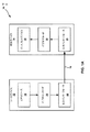
[0024]図1Aは、本開示で説明する態様による技法を利用し得る例示的なビデオコーディングシステム10を示すブロック図である。本明細書で使用し説明する「ビデオコーダ」または「コーダ」という用語は、ビデオエンコーダとビデオデコーダの両方を総称的に指す。本開示では、「ビデオコーディング」または「コーディング」という用語は、ビデオ符号化とビデオ復号とを総称的に指すことがある。ビデオエンコーダおよびビデオデコーダに加えて、本出願で説明する態様は、トランスコーダ(たとえば、ビットストリームを復号し、別のビットストリームを再符号化することができるデバイス)およびミドルボックス(たとえば、ビットストリームを変更、変換、および/または場合によっては操作することができるデバイス)など、他の関係するデバイスに拡張され得る。
[0024] FIG. 1A is a block diagram illustrating an example
[0025]図1Aに示されているように、ビデオコーディングシステム10は、宛先デバイス14によって後で復号されるべき符号化ビデオデータを生成するソースデバイス12を含む。図1Aの例では、ソースデバイス12および宛先デバイス14は、別個のデバイスを構成する。ただし、ソースデバイス12および宛先デバイス14は、図1Bの例に示されているように、同じデバイス上にあるかまたはそれの一部であり得ることに留意されたい。
[0025] As shown in FIG. 1A,
[0026]もう一度図1Aを参照すると、ソースデバイス12および宛先デバイス14は、それぞれ、デスクトップコンピュータ、ノートブック(たとえば、ラップトップ)コンピュータ、タブレットコンピュータ、セットトップボックス、いわゆる「スマート」フォンなどの電話ハンドセット、いわゆる「スマート」パッド、テレビジョン、カメラ、ディスプレイデバイス、デジタルメディアプレーヤ、ビデオゲームコンソール、ビデオストリーミングデバイスなどを含む、広範囲にわたるデバイスのいずれかを備え得る。様々な実施形態では、ソースデバイス12および宛先デバイス14は、ワイヤレス通信のために装備され得る。
[0026] Referring again to FIG. 1A, source device 12 and
[0027]宛先デバイス14は、復号されるべき符号化ビデオデータをリンク16を介して受信し得る。リンク16は、ソースデバイス12から宛先デバイス14に符号化ビデオデータを移動することが可能な任意のタイプの媒体またはデバイスを備え得る。図1Aの例では、リンク16は、ソースデバイス12が符号化ビデオデータをリアルタイムで宛先デバイス14に送信することを可能にするための通信媒体を備え得る。符号化ビデオデータは、ワイヤレス通信プロトコルなどの通信規格に従って変調され、宛先デバイス14に送信され得る。通信媒体は、無線周波数(RF)スペクトルあるいは1つまたは複数の物理伝送線路など、任意のワイヤレスまたはワイヤード通信媒体を備え得る。通信媒体は、ローカルエリアネットワーク、ワイドエリアネットワーク、またはインターネットなどのグローバルネットワークなど、パケットベースネットワークの一部を形成し得る。通信媒体は、ルータ、スイッチ、基地局、またはソースデバイス12から宛先デバイス14への通信を可能にするために有用であり得る任意の他の機器を含み得る。
[0028]図1Aの例では、ソースデバイス12は、ビデオソース18と、ビデオエンコーダ20と、出力インターフェース22とを含む。場合によっては、出力インターフェース22は、変調器/復調器(モデム)および/または送信機を含み得る。ソースデバイス12において、ビデオソース18は、ビデオキャプチャデバイス、たとえばビデオカメラ、以前にキャプチャされたビデオを含んでいるビデオアーカイブ、ビデオコンテンツプロバイダからビデオを受信するためのビデオフィードインターフェース、および/またはソースビデオとしてコンピュータグラフィックスデータを生成するためのコンピュータグラフィックスシステムなどのソース、あるいはそのようなソースの組合せを含み得る。一例として、ビデオソース18がビデオカメラである場合、ソースデバイス12および宛先デバイス14は、図1Bの例に示されているように、いわゆる「カメラフォン」または「ビデオフォン」を形成し得る。ただし、本開示で説明する技法は、概してビデオコーディングに適用可能であり得、ワイヤレスおよび/またはワイヤード適用例に適用され得る。
[0028] In the example of FIG. 1A, source device 12 includes
[0029]キャプチャされたビデオ、以前にキャプチャされたビデオ、またはコンピュータ生成されたビデオは、ビデオエンコーダ20によって符号化され得る。符号化ビデオデータは、ソースデバイス12の出力インターフェース22を介して宛先デバイス14に送信され得る。符号化ビデオデータは、さらに(または代替として)、復号および/または再生のための宛先デバイス14または他のデバイスによる後のアクセスのためにストレージデバイス31上に記憶され得る。図1Aおよび図1Bに示されているビデオエンコーダ20は、図2A示されているビデオエンコーダ20、または本明細書で説明する他のビデオエンコーダを備え得る。
[0029] The captured video, previously captured video, or computer generated video may be encoded by
[0030]図1Aの例では、宛先デバイス14は、入力インターフェース28と、ビデオデコーダ30と、ディスプレイデバイス32とを含む。場合によっては、入力インターフェース28は、受信機および/またはモデムを含み得る。宛先デバイス14の入力インターフェース28は、リンク16を介しておよび/またはストレージデバイス31から符号化ビデオデータを受信し得る。リンク16を介して通信され、またはストレージデバイス31上に与えられた符号化ビデオデータは、ビデオデータを復号する際に、ビデオデコーダ30などのビデオデコーダが使用するためのビデオエンコーダ20によって生成される様々なシンタックス要素を含み得る。そのようなシンタックス要素は、通信媒体上で送信された、記憶媒体上に記憶された、またはファイルサーバ記憶された符号化ビデオデータに含まれ得る。
[0030] In the example of FIG. 1A,
[0031]ディスプレイデバイス32は、宛先デバイス14と一体化されるかまたはその外部にあり得る。いくつかの例では、宛先デバイス14は、一体型ディスプレイデバイスを含み、また、外部ディスプレイデバイスとインターフェースするように構成され得る。他の例では、宛先デバイス14はディスプレイデバイスであり得る。概して、ディスプレイデバイス32は、復号ビデオデータをユーザに対して表示し、液晶ディスプレイ(LCD)、プラズマディスプレイ、有機発光ダイオード(OLED)ディスプレイ、または別のタイプのディスプレイデバイスなど、様々なディスプレイデバイスのいずれかを備え得る。
[0031]
[0032]関係する態様では、図1Bは例示的なビデオコーディングシステム10’を示し、ここにおいて、ソースデバイス12および宛先デバイス14はデバイス11上にあるかまたはそれの一部である。デバイス11は、「スマート」フォンなどの電話ハンドセットであり得る。デバイス11は、ソースデバイス12および宛先デバイス14と動作可能に通信している(随意に存在する)コントローラ/プロセッサデバイス13を含み得る。図1Bのビデオコーディングシステム10’およびそれの構成要素(components)は、場合によっては図1Aのビデオコーディングシステム10およびそれの構成要素と同様である。
In a related aspect, FIG. 1B shows an exemplary
[0033]ビデオエンコーダ20およびビデオデコーダ30は、DSCなどのビデオ圧縮規格に従って動作し得る。代替的に、ビデオエンコーダ20およびビデオデコーダ30は、代替的にMPEG−4,Part10,AVCと呼ばれるITU−T H.264規格、HEVCなど、他のプロプライエタリ規格または業界規格、またはそのような規格の拡張に従って動作し得る。ただし、本開示の技法は、いかなる特定のコーディング規格にも限定されない。ビデオ圧縮規格の他の例としてはMPEG−2およびITU−T H.263がある。
[0034]図1Aおよび図1Bの例には示されていないが、ビデオエンコーダ20およびビデオデコーダ30は、それぞれオーディオエンコーダおよびデコーダと統合され得、共通のデータストリームまたは別個のデータストリーム中のオーディオとビデオの両方の符号化を処理するために、適切なMUX−DEMUXユニット、または他のハードウェアおよびソフトウェアを含み得る。適用可能な場合、いくつかの例では、MUX−DEMUXユニットは、ITU H.223マルチプレクサプロトコル、またはユーザデータグラムプロトコル(UDP)などの他のプロトコルに準拠し得る。
Although not shown in the examples of FIGS. 1A and 1B,
[0035]ビデオエンコーダ20およびビデオデコーダ30はそれぞれ、1つまたは複数のマイクロプロセッサ、デジタル信号プロセッサ(DSP)、特定用途向け集積回路(ASIC)、フィールドプログラマブルゲートアレイ(FPGA)、ディスクリート論理、ソフトウェア、ハードウェア、ファームウェアなど、様々な好適なエンコーダ回路のいずれか、またはそれらの任意の組合せとして実装され得る。本技法が部分的にソフトウェアで実装されるとき、デバイスは、好適な非一時的コンピュータ可読媒体にソフトウェアの命令を記憶し、1つまたは複数のプロセッサを使用してその命令をハードウェアで実行して、本開示の技法を実行し得る。ビデオエンコーダ20およびビデオデコーダ30の各々は1つまたは複数のエンコーダまたはデコーダ中に含まれ得、そのいずれも、それぞれのデバイスにおいて複合エンコーダ/デコーダの一部として統合され得る。
ビデオコーディングプロセス
[0036]上記で手短に述べたように、ビデオエンコーダ20はビデオデータを符号化する。ビデオデータは、1つまたは複数のピクチャを備え得る。ピクチャの各々は、ビデオの一部を形成する静止画像である。いくつかの事例では、ピクチャはビデオ「フレーム」と呼ばれることがある。ビデオエンコーダ20がビデオデータを符号化するとき、ビデオエンコーダ20はビットストリームを生成し得る。ビットストリームは、ビデオデータのコード化表現を形成するビットのシーケンスを含み得る。ビットストリームはコード化ピクチャと関連データとを含み得る。コード化ピクチャは、ピクチャのコード化表現である。
[0035]
Video coding process
[0036] As mentioned briefly above,
[0037]ビットストリームを生成するために、ビデオエンコーダ20は、ビデオデータ中の各ピクチャに対して符号化演算を実行し得る。ビデオエンコーダ20がピクチャに対して符号化演算を実行するとき、ビデオエンコーダ20は、一連のコード化ピクチャと関連データとを生成し得る。関連データは、QPなど、コーディングパラメータのセットを含み得る。コード化ピクチャを生成するために、ビデオエンコーダ20は、ピクチャを等しいサイズのビデオブロックに区分し得る。ビデオブロックはサンプルの2次元アレイであり得る。コーディングパラメータは、ビデオデータのあらゆるブロックについてコーディングオプション(たとえば、コーディングモード)を定義し得る。コーディングオプションは、所望のレートひずみ性能を達成するために選択され得る。
[0037] To generate a bitstream,
[0038]いくつかの例では、ビデオエンコーダ20はピクチャを複数のスライスに区分し得る。スライスの各々は、画像またはフレーム中の領域の残りからの情報なしに独立して復号され得る、画像(たとえば、フレーム)中の空間的に別個の領域を含み得る。各画像またはビデオフレームは単一のスライス中で符号化され得るか、またはそれはいくつかのスライス中で符号化され得る。DSCでは、各スライスを符号化するために割り振られるターゲットビットは、実質的に一定であり得る。ピクチャに対して符号化演算を実行することの一部として、ビデオエンコーダ20は、ピクチャの各スライスに対して符号化演算を実行し得る。ビデオエンコーダ20がスライスに対して符号化演算を実行するとき、ビデオエンコーダ20は、スライスに関連付けられた符号化データを生成し得る。スライスに関連付けられた符号化データは「コード化スライス」と呼ばれることがある。
DSCビデオエンコーダ
[0039]図2Aは、本開示で説明する態様による技法を実装し得るビデオエンコーダ20の一例を示すブロック図である。ビデオエンコーダ20は、本開示の技法の一部または全部を実行するように構成され得る。いくつかの例では、本開示で説明する技法は、ビデオエンコーダ20の様々な構成要素間で共有され得る。いくつかの例では、追加または代替として、プロセッサ(図示せず)が、本開示で説明する技法の一部または全部を実行するように構成され得る。
[0038] In some examples,
DSC video encoder
[0039] FIG. 2A is a block diagram illustrating an example of a
[0040]説明の目的で、本開示では、DSCコーディングのコンテキストにおいてビデオエンコーダ20について説明する。ただし、本開示の技法は、他のコーディング規格または方法に適用可能であり得る。
[0040] For purposes of explanation, this disclosure describes
[0041]図2Aの例では、ビデオエンコーダ20は複数の機能構成要素を含む。ビデオエンコーダ20の機能構成要素は、色空間変換器105と、バッファ110と、平坦度検出器115と、レートコントローラ120と、予測器、量子化器、および再構成器構成要素125と、ラインバッファ130と、インデックスカラー履歴135と、エントロピーエンコーダ140と、サブストリームマルチプレクサ145と、レートバッファ150とを含む。他の例では、ビデオエンコーダ20は、より多数の、より少数の、または異なる機能構成要素を含み得る。
[0041] In the example of FIG. 2A,
[0042]色空間105変換器は、入力色空間をコーディング実装形態において使用される色空間に変換し得る。たとえば、例示的な一実施形態では、入力ビデオデータの色空間は、赤、緑、および青(RGB)色空間中にあり、コーディングは、ルミナンスY、クロミナンスグリーンCg、およびクロミナンスオレンジCo(YCgCo)色空間において実装される。色空間変換は、ビデオデータへのシフトおよび追加を含む(1つまたは複数の)方法によって実行され得る。他の色空間中の入力ビデオデータが処理され得、他の色空間への変換も実行され得ることに留意されたい。 [0042] A color space 105 converter may convert an input color space to a color space used in a coding implementation. For example, in an exemplary embodiment, the color space of the input video data is in red, green, and blue (RGB) color spaces, and the coding is: luminance Y, chrominance green Cg, and chrominance orange Co (YCgCo) Implemented in color space. Color space conversion may be performed by method (s) that include shifting and adding to video data. It should be noted that input video data in other color spaces may be processed and conversion to other color spaces may also be performed.
[0043]関係する態様では、ビデオエンコーダ20は、バッファ110、ラインバッファ130、および/またはレートバッファ150を含み得る。たとえば、バッファ110は、色空間変換されたビデオデータを、ビデオエンコーダ20の他の部分によるそれの使用に先立って保持し得る。別の例では、色空間変換されたデータはより多くのビットを必要とし得るので、ビデオデータはRGB色空間中で記憶され得、色空間変換が必要に応じて実行され得る。
[0043] In related aspects,
[0044]レートバッファ150はビデオエンコーダ20においてレート制御機構の一部として機能し得、このことについて、レートコントローラ120に関して以下でより詳細に説明する。各ブロックを符号化することに費やされるビットは、大いに、実質的に、ブロックの性質に基づいて変動することがある。レートバッファ150は、圧縮されたビデオにおけるレート変動を平滑化することができる。いくつかの実施形態では、ビットが固定ビットレート(CBR)でバッファから取り出されるCBRバッファモデルが採用される。CBRバッファモデルでは、ビデオエンコーダ20がビットストリームにあまりに多くのビットを加えた場合、レートバッファ150はオーバーフローし得る。一方、ビデオエンコーダ20は、レートバッファ150のアンダーフローを防ぐために、十分なビットを加えなければならない。
[0044]
[0045]ビデオデコーダ側では、ビットは、固定ビットレートでビデオデコーダ30のレートバッファ155(以下でさらに詳細に説明する図2Bを参照)に加えられ得、ビデオデコーダ30は、各ブロックについて可変数のビットを削除し得る。適切な復号を保証するために、ビデオデコーダ30のレートバッファ155は、圧縮されたビットストリームの復号中に「アンダーフロー」または「オーバーフロー」すべきでない。
[0045] On the video decoder side, bits may be added to the rate buffer 155 of the video decoder 30 (see FIG. 2B described in more detail below) at a fixed bit rate, and the
[0046]いくつかの実施形態では、バッファフルネス(BF)は、バッファに現在あるビットの数を表す値BufferCurrentSizeと、レートバッファ150のサイズ、すなわち、任意の時点においてレートバッファ150に記憶され得るビットの最大数を表すBufferMaxSizeとに基づいて定義され得る。BFは次のように計算され得る。
[0046] In some embodiments, buffer fullness (BF) may be stored in value BufferCurrentSize, which represents the number of bits currently in the buffer, and the size of

[0047]平坦度検出器115は、ビデオデータ中の複雑な(complex)(すなわち、平坦でない)エリアからビデオデータ中の平坦な(flat)(すなわち、単純なまたは均一な)エリアへの変化を検出することができる。「複雑な」および「平坦な」という用語は、本明細書では、概して、ビデオエンコーダ20がビデオデータのそれぞれの領域を符号化することの困難さを指すために使用する。したがって、本明細書で使用する「複雑な」という用語は、概して、ビデオデータの領域が、ビデオエンコーダ20が符号化することが複雑または困難であることを表し、たとえば、テクスチャードビデオデータ、高い空間周波数、および/または符号化することが複雑である他の特徴を含み得る。たとえば、ビデオデータの領域は、領域を符号化するために必要とされるビットの数がしきい値よりも大きいとき、複雑な領域であると決定され得る。本明細書で使用する「平坦な」という用語は、概して、ビデオデータの領域が、ビデオエンコーダ20がエンコーダすることが単純であることを表し、たとえば、ビデオデータ中の滑らかな勾配、低い空間周波数、および/または符号化することが単純である他の特徴を含み得る。たとえば、ビデオデータの領域は、領域を符号化するために必要とされるビットの数がしきい値よりも小さいとき、平坦な領域であると決定され得る。
[0047]
[0048]しかしながら、実装形態に応じて、所与の領域が複雑であるのか平坦であるのかの決定は、使用される符号化規格、ビデオエンコーダ20に含まれる具体的なハードウェア、符号化されるべきビデオデータのタイプなどにも基づいて決定され得る。さらに、ビデオデータ領域のいくつかのプロパティが、領域を符号化するためにいくつのビットが必要とされるかに影響を及ぼし得、たとえば、高いテクスチャおよび/または高い空間周波数領域は、より低いテクスチャおよび/またはより低い空間周波数領域よりも多くのビットが符号化されることを必要とし得る。同様に、ランダムノイズを備える領域は、ビデオデータのより構造化された領域と比較して、多数のビットが符号化されることを必要とし得る。したがって、いくつかの実装形態では、ビデオデータの領域は、テクスチャおよび/または空間周波数の測度(たとえば、複雑度値)を複雑度しきい値と比較することによって、複雑な領域および/または平坦な領域として識別され得る。複雑な領域と平坦な領域との間の遷移が、符号化ビデオデータ中の量子化アーティファクトを低減するために、ビデオエンコーダ20によって使用され得る。詳細には、レートコントローラ120、ならびに予測器、量子化器、および再構成器構成要素125は、複雑な領域から平坦な領域への遷移が識別されたとき、そのような量子化アーティファクトを低減することができる。
[0048] However, depending on the implementation, the determination of whether a given area is complex or flat depends on the encoding standard used, the specific hardware included in the
[0049]レートコントローラ120は、コーディングパラメータのセット、たとえば、QPを決定する。QPは、レートバッファ150がオーバーフローまたはアンダーフローしないことを保証するターゲットビットレートについてピクチャ品質を最大にするために、レートバッファ150のバッファフルネスとビデオデータの画像アクティビティとに基づいて、レートコントローラ120によって調整され得る。レートコントローラ120はまた、最適レートひずみ性能を達成するために、ビデオデータの各ブロックについて特定のコーディングオプション(たとえば、特定のモード)を選択する。レートコントローラ120は、再構成された画像のひずみを、それがビットレート制約を満たすように、すなわち、全体的実コーディングレートがターゲットビットレート内に収まるように最小化する。
Rate controller 120 determines a set of coding parameters, eg, QP. The QP is based on the buffer fullness of the
[0050]予測器、量子化器、および再構成器構成要素125は、ビデオエンコーダ20の少なくとも3つの符号化演算を実行し得る。予測器、量子化器、および再構成器構成要素125は、いくつかの異なるモードで予測を実行し得る。1つの例示的なプレディケーションモードは、メディアン適応予測の変更バージョンである。メディアン適応予測はロスレスJPEG規格(JPEG−LS)によって実装され得る。予測器、量子化器、および再構成器構成要素125によって実行され得るメディアン適応予測の変更バージョンは、3つの連続するサンプル値の並列予測を可能にし得る。別の例示的な予測モードはブロック予測である。ブロック予測では、サンプルは、前に再構成されたピクセルから左側に予測される。ビデオエンコーダ20およびビデオデコーダ30は、両方とも、ブロック予測使用を決定するために、再構成されたピクセルに対して同じ探索を実行することができ、したがって、ビットはブロック予測モードで送られる必要がない。成分範囲の中点を使用してサンプルが予測される中点予測モードも実装され得る。中点予測モードは、ワーストケースサンプルにおいてさえも、圧縮されたビデオに必要なビットの数の制限(bounding)を可能にし得る。
The predictor, quantizer, and reconstructor component 125 may perform at least three coding operations of the
[0051]予測器、量子化器、および再構成器構成要素125はまた、量子化を実行する。たとえば、量子化は、シフタを使用して実装され得る2のべき乗量子化器(power-of-2 quantizer)を介して実行され得る。2のべき乗量子化器の代わりに他の量子化技法が実装され得ることに留意されたい。予測器、量子化器、および再構成器構成要素125によって実行される量子化は、レートコントローラ120によって決定されたQPに基づき得る。最終的に、予測器、量子化器、および再構成器構成要素125はまた、予測値に逆量子化残差を加算することと、結果がサンプル値の有効範囲の外側にないことを保証することとを含む再構成を実行する。 [0051] The predictor, quantizer, and reconstructor component 125 also perform quantization. For example, quantization may be performed via a power-of-2 quantizer, which may be implemented using a shifter. It should be noted that other quantization techniques may be implemented instead of a power-of-two quantizer. The quantization performed by predictor, quantizer, and reconstructor component 125 may be based on the QP determined by rate controller 120. Finally, the predictor, quantizer, and reconstructor components 125 also ensure that the inverse quantization residual is added to the predicted value and that the result is not outside the valid range of the sample value Perform a reconfiguration that includes
[0052]予測器、量子化器、および再構成器構成要素125によって実行される予測、量子化、および再構成に対する上記で説明した例示的な手法は、例示的なものにすぎず、他の手法が実装され得ることに留意されたい。また、予測器、量子化器、および再構成器構成要素125は、予測、量子化、および/または再構成を実行するための(1つまたは複数の)副構成要素(subcomponent(s))を含み得ることに留意されたい。さらに、予測、量子化、および/または再構成は、予測器、量子化器、および再構成器構成要素125の代わりにいくつかの別個のエンコーダ構成要素によって実行され得ることに留意されたい。 [0052] The above-described exemplary approaches to prediction, quantization, and reconstruction performed by the predictor, quantizer, and reconstruction component 125 are merely illustrative and others Note that an approach may be implemented. The predictor, quantizer, and reconstructor component 125 may also be configured to perform prediction, quantization, and / or reconstruction (subcomponent (s)). Note that it can be included. Further, it should be noted that prediction, quantization, and / or reconstruction may be performed by several separate encoder components instead of the predictor, quantizer, and reconstructor components 125.
[0053]ラインバッファ130は、予測器、量子化器、および再構成器構成要素125ならびにインデックスカラー履歴135が、バッファされたビデオデータを使用することができるように、予測器、量子化器、および再構成器構成要素125からの出力を保持する。インデックスカラー履歴135は、最近使用されたピクセル値を記憶する。これらの最近使用されたピクセル値は、専用シンタックスを介してビデオエンコーダ20によって直接参照され得る。
[0053]
[0054]エントロピーエンコーダ140は、インデックスカラー履歴135と、平坦度検出器115によって識別された平坦度遷移とに基づいて、予測器、量子化器、および再構成器構成要素125から受信された予測残差を符号化する。いくつかの例では、エントロピーエンコーダ140は、サブストリームエンコーダごとにクロックごとに3つのサンプルを符号化し得る。サブストリームマルチプレクサ145は、ヘッダレスパケット多重化方式に基づいてビットストリームを多重化し得る。これは、ビデオデコーダ30が並列に3つのエントロピーデコーダを動作させることを可能にし、クロックごとの3つのピクセルの復号を可能にする。サブストリームマルチプレクサ145は、パケットがビデオデコーダ30によって効率的に復号され得るようにパケット順序を最適化し得る。クロックごとの2のべき乗個のピクセル(たとえば、2つのピクセル/クロックまたは4つのピクセル/クロック)の復号を容易にし得る、エントロピーコーディングに対する異なる手法が実装され得ることに留意されたい。
DSCビデオデコーダ
[0055]図2Bは、本開示で説明する態様による技法を実装し得るビデオデコーダ30の一例を示すブロック図である。ビデオデコーダ30は、本開示の技法の一部または全部を実行するように構成され得る。いくつかの例では、本開示で説明する技法は、ビデオエンコーダ30の様々な構成要素間で共有され得る。いくつかの例では、追加または代替として、プロセッサ(図示せず)が、本開示で説明する技法の一部または全部を実行するように構成され得る。
DSC video decoder
[0055] FIG. 2B is a block diagram illustrating an example of a
[0056]説明の目的で、本開示では、DSCコーディングのコンテキストにおいてビデオデコーダ30について説明する。ただし、本開示の技法は、他のコーディング規格または方法に適用可能であり得る。
[0056] For purposes of explanation, this disclosure describes
[0057]図2Bの例では、ビデオデコーダ30は複数の機能構成要素を含む。ビデオデコーダ30の機能構成要素は、レートバッファ155と、サブストリームデマルチプレクサ160と、エントロピーデコーダ165と、レートコントローラ170と、予測器、量子化器、および再構成器構成要素175と、インデックスカラー履歴180と、ラインバッファ185と、色空間変換器190とを含む。ビデオデコーダ30の図示された構成要素は、図2A中のビデオエンコーダ20に関して上記で説明した対応する構成要素に類似する。したがって、ビデオデコーダ30の構成要素の各々は、上記で説明したビデオエンコーダ20の対応する構成要素と同様の様式で動作し得る。
DSCにおけるスライス
[0058]上述のように、スライスは、概して、画像またはフレーム中の領域の残りからの情報を使用することなしに独立して復号され得る、画像またはフレーム中の空間的に別個の領域を指す。各画像またはビデオフレームは単一のスライス中で符号化され得るか、またはそれはいくつかのスライス中で符号化され得る。DSCでは、各スライスを符号化するために割り振られるターゲットビットは、実質的に一定であり得る。
DSCのためにQPを選択すること
[0059]QPを計算することは、レート制御プロセスにおいて望ましいステップであり得、コーディング方式のレートひずみ(RD)性能に大きい影響を及ぼし得る。一実施形態では、QPは、経験的レートひずみモデルを必要とするレートひずみ関係を最適化するように選択される。たとえば、QPは、所与のレートひずみ経験的モデルに最も良く適合するように計算され得る。この手法は、特定のコンテンツ、たとえば、自然コンテンツで動作するとき、うまく動作し得る。しかしながら、自然グラフィックス、合成グラフィックス、コンピュータグラフィックス、フラクタルなどを含むいくつかのタイプのコンテンツで動作するとき、異なるタイプのコンテンツについて効率的に動作するレートひずみモデルを確立することは困難であり得る。たとえば、レートひずみモデルのための単一の閉形式表現を確立することは困難であり得る。この困難を克服するために、レートひずみモデルの知識を必要としないかまたはレートひずみモデルに依存しないQPを計算するための方法を実装することが望ましいことがある。
[0057] In the example of FIG. 2B,
Slice in DSC
[0058] As mentioned above, slices generally refer to spatially distinct regions in an image or frame that can be decoded independently without using information from the rest of the region in the image or frame. . Each image or video frame may be encoded in a single slice, or it may be encoded in several slices. In DSC, the target bits allocated to encode each slice may be substantially constant.
Choosing a QP for DSC
[0059] Computing QP may be a desirable step in the rate control process and may have a significant impact on the rate distortion (RD) performance of the coding scheme. In one embodiment, the QP is selected to optimize rate-distortion relationships that require an empirical rate-distortion model. For example, QP can be calculated to best fit a given rate distortion empirical model. This approach may work well when operating on specific content, for example natural content. However, when working with several types of content, including natural graphics, synthetic graphics, computer graphics, fractals, etc., it is difficult to establish a rate-distortion model that works efficiently for different types of content. obtain. For example, it may be difficult to establish a single closed form representation for rate distortion models. To overcome this difficulty, it may be desirable to implement a method to calculate a rate distortion model independent QP that does not require knowledge of the rate distortion model.
[0060]これらおよび他の困難に対処するために、いくつかの態様による技法は、レートひずみモデルを考慮することなしに最適QPを決定することができる。レートひずみモデルは、DSCにおける1つまたは複数のコーディングモード、あるいは1つまたは複数の異なるタイプのコンテンツに関連付けられ得る。レートひずみモデルは、経験的データに基づき得る。一実施形態では、本技法は、(1)現在ブロックのためのビットバジェットと、前のブロックを符号化するためのビットの数との間の差と、(2)現在ブロックのためのビットバジェットと、前のブロックを符号化するためのビットの数との間の差の関数であるQP調整値とに基づいて、QPを決定することができる。現在ブロックのための決定されたQPは、バッファフルネス、現在ブロックの平坦度などに基づいてさらに調整され得る。 [0060] To address these and other difficulties, techniques in accordance with some aspects can determine the optimal QP without considering rate-distortion models. The rate distortion model may be associated with one or more coding modes in the DSC, or one or more different types of content. Rate distortion models may be based on empirical data. In one embodiment, the techniques include (1) the difference between the bit budget for the current block and the number of bits for encoding the previous block, and (2) the bit budget for the current block The QP can be determined based on and the QP adjustment value, which is a function of the difference between the number of bits to encode the previous block. The determined QP for the current block may be further adjusted based on buffer fullness, flatness of the current block, and so on.
[0061]このようにして、本技法は、コーディングモードまたは特定のタイプのコンテンツに関連付けられた特定のレートひずみモデルに依拠することなしに、QP値を選択することができる。このことは、レートひずみを確立することが、時間がかかり、かなりの量の労力を伴うことがあるので、コストおよび/またはリソースを節約することができる。さらに、本技法は、異なるタイプのコンテンツでうまく動作するQPを決定することができる。 [0061] Thus, the techniques may select QP values without relying on a coding mode or a particular rate distortion model associated with a particular type of content. This can save costs and / or resources as establishing rate distortion can be time consuming and can involve a significant amount of effort. Furthermore, the techniques can determine QPs that work well with different types of content.
[0062]DSCにおいてQPを選択することに関係するいくつかの詳細について、たとえば、例示的な実施形態に関して以下で説明する。本開示全体にわたって使用される様々な用語は、それらの通常の意味を有する広義の用語である。いくつかの実施形態では、QPは、量子化の程度を制御するために量子化プロセスにおいて使用されるパラメータを指すことがある。たとえば、量子化プロセスは、ビットレートをさらに低減するために、残差を量子化する。量子化プロセスは、残差の一部または全部に関連するビット深度を低減し得る。量子化の程度は、量子化パラメータを調整することによって変更され得る。たとえば、量子化パラメータは、残差の量子化を決定するために使用される。QP値が低いとき、詳細な視覚情報の大部分は保持され得る。低いQP値は、概して、より低いひずみを与えるが、より高いビットレートという代償を払う。QP値が増加するにつれて、より多くのビットプレーンが廃棄され得、このことは、ビットレートを低減するが、ひずみを増加させるという代償を払う。いくつかの実施形態では、本技法は、レートひずみモデルとは無関係にQPを決定する、レートひずみモデルに応じずにQPを決定する、などを行うことができる。いくつかの態様によれば、レートひずみモデルを考慮することなしにQPを決定することは、レートひずみモデルとは無関係にQPを決定すること、レートひずみモデルに応じずにQPを決定することなどと呼ばれることもある。レートひずみモデルは、コーディングされるべきビデオデータのコンテンツのタイプに関連付けられ得るか、特定のモードに関連付けられ得るか、またはその両方である。コンテンツのタイプはコンテンツの実体とは異なることがある。コンテンツのタイプは、自然コンテンツ、合成コンテンツ、コンピュータグラフィックス、フラクタルなどを含み得る。レートひずみモデルは、コンテンツの特定のタイプに関連付けられ、実際のコンテンツ自体に関連付けられないことがある。
例示的な実施形態
[0063]一実施形態では、経験的レートひずみモデルを知ることなしに異なるタイプのコンテンツについてうまく動作するQPを計算するための装置および方法が提供される。特定のコーディングモード(またはオプション)について、現在ブロックのための対応するQP値は、以下で説明するステップから計算され得る。この技法は、各コーディングモード(またはオプション)について、そのコーディングモード(またはオプション)に関連付けられたQPを計算するために独立して使用され得る。たとえば、現在ブロックについて、QP値は、以下で説明するステップを使用して、各コーディングモードについて計算され、たとえばブロックごとに追跡され得る。いくつかの実施形態では、各コーディングモードに対応するQPを計算する代わりに、本技法は、すべてのコーディングモードをコーディングするために使用され得る単一のQP値を計算し得る。たとえば、現在ブロックのための単一のQP値は、以下で説明するステップから計算され得る。
1. ビットバジェットを計算する
[0064](ここではbitBudgetとして示される)現在ブロックのためのビットバジェットは、スライス中に残っているビットの数(numSliceBitsRemaining)と、スライス中で符号化されるべきピクセルの数(numSlicePixelsRemaining)と、現在ブロック中のピクセルの数(numPixelsInBlock)とを考慮することによって計算される。さらに、バッファ中のビットの数(たとえば、BF)は、bitBudgetを計算する間に考慮され得る。
[0062] Some details pertaining to selecting a QP in a DSC are described below, for example, with respect to an exemplary embodiment. The various terms used throughout the present disclosure are broad terms having their ordinary meanings. In some embodiments, QP may refer to parameters used in the quantization process to control the degree of quantization. For example, the quantization process quantizes the residual to further reduce the bit rate. The quantization process may reduce the bit depth associated with some or all of the residuals. The degree of quantization can be changed by adjusting the quantization parameter. For example, quantization parameters are used to determine the quantization of the residual. When the QP value is low, most of the detailed visual information may be retained. Low QP values generally give lower distortion but at the cost of higher bit rates. As the QP value increases, more bit planes may be discarded, which reduces the bit rate but at the cost of increasing distortion. In some embodiments, the techniques may determine the QP independently of the rate-distortion model, determine the QP not depending on the rate-distortion model, and so on. According to some aspects, determining the QP without considering the rate-distortion model, determining the QP independently of the rate-distortion model, determining the QP not depending on the rate-distortion model, etc. Sometimes called. The rate distortion model may be associated with the type of content of the video data to be coded, may be associated with a particular mode, or both. The type of content may be different from the content entity. Types of content may include natural content, synthetic content, computer graphics, fractals, and the like. Rate distortion models are associated with particular types of content and may not be associated with the actual content itself.
Exemplary embodiment
[0063] In one embodiment, an apparatus and method are provided for computing a QP that works well for different types of content without knowing the empirical rate distortion model. For a particular coding mode (or option), the corresponding QP values for the current block may be calculated from the steps described below. This technique may be used independently to calculate, for each coding mode (or option), the QP associated with that coding mode (or option). For example, for the current block, the QP value may be calculated for each coding mode, eg, tracked block by block, using the steps described below. In some embodiments, instead of computing the QPs corresponding to each coding mode, the techniques may compute a single QP value that may be used to code all coding modes. For example, a single QP value for the current block may be calculated from the steps described below.
1. Calculate the bit budget
[0064] The bit budget for the current block (shown here as bitBudget) is the number of bits remaining in the slice (numSliceBitsRemaining) and the number of pixels to be coded in the slice (numSlicePixelsRemaining), Calculated by considering the number of pixels in the current block (numPixelsInBlock). Additionally, the number of bits in the buffer (eg, BF) may be considered while calculating bitBudget.
一例では、現在ブロックのためのビットレートは、スライス中に残っているビットの数を、符号化される必要があるスライス中のピクセルの数で除算することによって計算される。したがって、bitBudgetは、次のように計算される。 In one example, the bit rate for the current block is calculated by dividing the number of bits remaining in the slice by the number of pixels in the slice that needs to be encoded. Therefore, bitBudget is calculated as follows.
別の例では、bitBudgetは、スライス内の現在ブロックの位置に応じて計算され得る。たとえば、bitBudgetは、レートdecBitBudgetによって線形的に減少させられ得、ここで、decBitBudgetは、現在スライス中で符号化されるブロックの数と、現在スライス中のブロックの総数とに応じて計算され得る。
2. ビットバジェットと、前のブロックを符号化するためのビットの数との間の差を計算する
[0065]特定のモードについての、bitBudgetと(prevBlockBitsとして示される)前のブロックを符号化するために必要とされたビットの数との間の差が計算される。この差は、diffBitsとして表され得、diffBits=prevBlockBits−bitBudgetとして計算され得る。さらに、diffBitsは、たとえば、diffBits=diffBits/(numPixelsinBlock*targetBitRate)として正規化され得る。
In another example, bitBudget may be calculated according to the position of the current block in the slice. For example, bitBudget may be linearly reduced by the rate decBitBudget, where decBitBudget may be calculated according to the number of blocks encoded in the current slice and the total number of blocks in the current slice.
2. Calculate the difference between the bit budget and the number of bits to encode the previous block
[0065] The difference between bitBudget and the number of bits needed to encode the previous block (shown as prevBlockBits) is calculated for the particular mode. This difference may be expressed as diffBits and may be calculated as diffBits = prevBlockBits-bitBudget. Furthermore, diffBits may be normalized, for example, as diffBits = diffBits / (numPixelsinBlock * targetBitRate).
[0066]いくつかの実施形態では、前のブロックをコーディングするために使用されたコーディングモードにかかわらず、単一のQPが、導出され、すべてのコーディングモードのために使用されるべきであるとき、(prevBlockBitsとして示される)前のブロックをコーディングすることに費やされたビットの数は、diffBitsを計算するために使用される。
3. 差の関数としてQP調整値を決定する
[0067]QpAdjは、ステップ2において計算されたdiffBitsの絶対値の関数として計算される調整値を表すものとする。関数は、diffBitsの絶対値が増加するにつれて、QpAdjの値を線形的にまたは非線形的に増加させ得る。
[0066] In some embodiments, regardless of the coding mode used to code the previous block, when a single QP should be derived and used for all coding modes The number of bits spent coding the previous block (shown as prevBlockBits) is used to calculate diffBits.
3. Determine the QP adjustment value as a function of the difference
[0067] Let QpAdj denote the adjustment value calculated as a function of the absolute value of diffBits calculated in step 2. The function may increase the value of QpAdj linearly or non-linearly as the absolute value of diffBits increases.
一例では、diffBitsの絶対値は、K個のしきい値を使用してK+1個の範囲に分類され得る。たとえば、K個のしきい値(たとえば、1〜K)があり得、連続する2つのしきい値は範囲の開始および終了を定義することができる。たとえば、範囲1は0としきい値1との間にあり得、範囲2はしきい値1としきい値2との間にあり得、以下同様である。K個のしきい値の場合、K+1個の範囲があり得る。各範囲について、特定のQpAdj値があり、ここで、QpAdj値は、範囲が増加するにつれて増加する。 In one example, the absolute value of diffBits may be classified into K + 1 ranges using K thresholds. For example, there may be K thresholds (e.g., 1 to K), and two consecutive thresholds may define the start and end of the range. For example, range 1 can be between 0 and threshold 1, range 2 can be between threshold 1 and threshold 2, and so on. For K thresholds, there may be K + 1 ranges. For each range there is a specific QpAdj value, where the QpAdj value increases as the range increases.
いくつかの実施形態では、QpAdjは、絶対値を取ることなしに、diffBitsの関数として計算され得る。K+1個の範囲およびそれぞれのQpAdj値を分類するために使用されるK個のしきい値[しきい値1,しきい値2,...しきい値k]は、diffBitsの符号値に応じて異なり得る。 In some embodiments, QpAdj may be calculated as a function of diffBits without taking absolute values. K thresholds used to classify K + 1 ranges and respective QpAdj values [Threshold 1, Thresholds 2,. . . The threshold value k] may differ depending on the code value of diffBits.
− 一例では、diffBits>0であるとき、diffBitsは、K個のしきい値を使用してK+1個の範囲に分類され得る。各範囲について、特定のQpAdj値があり、ここで、QpAdj値は、範囲が増加するにつれて増加する。そうではなく、diffBits≦0である場合、diffBitsの絶対値は、J個のしきい値を使用してJ+1個の範囲に分類され得る。また、各範囲について、範囲が増加するにつれて増加する特定のQpAdj値がある。 -In one example, when diffBits> 0, diffBits may be classified into K + 1 ranges using K thresholds. For each range there is a specific QpAdj value, where the QpAdj value increases as the range increases. Otherwise, if diffBits ≦ 0, then the absolute value of diffBits may be classified into J + 1 ranges using J thresholds. Also, for each range, there is a specific QpAdj value that increases as the range increases.
− 一例では、diffBits≧0であるとき、diffBitsは、K個のしきい値を使用してK+1個の範囲に分類され得る。各範囲について、特定のQpAdj値があり、ここで、QpAdj値は、範囲が増加するにつれて増加する。そうではなく、diffBits<0である場合、diffBitsの絶対値は、J個のしきい値を使用してJ+1個の範囲に分類され得る。また、各範囲について、範囲が増加するにつれて増加する特定のQpAdj値があり得る。 In one example, when diffBits ≧ 0, diffBits may be classified into K + 1 ranges using K thresholds. For each range there is a specific QpAdj value, where the QpAdj value increases as the range increases. Otherwise, if diffBits <0, then the absolute value of diffBits may be classified into J + 1 ranges using J thresholds. Also, for each range, there may be specific QpAdj values that increase as the range increases.
− 一例では、diffBits≦0またはdiffBits<0であるとき、diffBitsは、J個のしきい値を使用してJ+1個の範囲に分類され得る。また、各範囲について、範囲が減少するにつれて減少する特定のQpAdj値がある。この場合、QpAdjは負の値を取り得ることに留意されたい。 In one example, when diffBits ≦ 0 or diffBits <0, diffBits may be classified into J + 1 ranges using J thresholds. Also, for each range, there are specific QpAdj values that decrease as the range decreases. Note that in this case, QpAdj can have a negative value.
− 一例では、diffBits>0であるときとdiffBits≦0であるときのしきい値の数は同じであるが(K=J)、個々の値は同じであることも同じでないこともある。 In one example, the number of thresholds when diffBits> 0 and diffBits ≦ 0 is the same (K = J), but the individual values may or may not be the same.
− 一例では、diffBits≧0であるときとdiffBits<0であるときのしきい値の数は同じであるが(K=J)、個々の値は同じであることも同じでないこともある。 In one example, the number of thresholds when diffBitsits0 and diffBits <0 is the same (K = J), but the individual values may or may not be the same.
− 一例では、diffBits>0の場合とdiffBits≦0の場合の両方についてK個のしきい値が同じであるときでも、各範囲のための関連付けられたQpAdj値は、diffBits>0とdiffBits≧0とについて同じであることも同じでないこともある。 In one example, the associated QpAdj values for each range are diffBits> 0 and diffBits ≧ 0, even when K thresholds are the same for both diffBits> 0 and diffBits ≦ 0. And may or may not be the same.
− 一例では、diffBits≧0の場合とdiffBits<0の場合の両方についてK個のしきい値が同じであるときでも、各範囲のための関連付けられたQpAdj値は、diffBits≧0とdiffBits>0とについて同じであることも同じでないこともある。
4. 現在ブロックのためのQP値を決定する
[0068]現在ブロックのためのQP値(currQP)は、ステップ2におけるdiffBitsと、ステップ3において計算されたQpAdjと、前のブロックをコーディングするために使用された同じモードに対応する前のブロックを符号化するために使用されたQP値(prevQP)とに基づいて決定され得る。より正確には、currQPを計算するために以下の式が使用される。
In one example, the associated QpAdj values for each range are diffBits 0 0 and diffBits> 0, even when K thresholds are the same for both diffBits 0 0 and diffBits <0. And may or may not be the same.
4. Determine the QP value for the current block
[0068] The QP value (currQP) for the current block is the previous block corresponding to the diffBits in step 2, the QpAdj calculated in step 3, and the same mode used to code the previous block. It may be determined based on the QP value (prevQP) used to encode. More precisely, the following equation is used to calculate currQP.
![]()
![]()
一例では、currQP=prevQP+QPAdjである。 In one example, currQP = prevQP + QPAdj.
一実施形態では、前のブロックのコーディングモードにかかわらず、単一のQPが、導出され、すべてのコーディングモードのために使用されるべきであるとき、前のブロックを符号化するために使用されたQP値(prevQP)は、currQPの計算のために使用される。
5. バッファフルネスに基づいて現在ブロックのためのQP値を調整する
[0069]BFに応じて、currQPは、バッファエラーを回避するためにさらに調整され得る。より詳細には、currQPは、BFがあるしきい値を超えるとき、さらに増分され得、これはバッファオーバーフローを防ぎ得る。同様に、currQPは、BFがあるしきい値を下回るとき、さらに減分され得、これは、アンダーフローを防ぎ得る。
In one embodiment, regardless of the coding mode of the previous block, when a single QP is derived and should be used for all coding modes, it is used to encode the previous block. The QP value (prev QP) is used for the calculation of curr QP.
5. Adjust the QP value for the current block based on buffer fullness
[0069] Depending on BF, currQP may be further adjusted to avoid buffer errors. More specifically, currQP may be further incremented when BF exceeds a certain threshold, which may prevent buffer overflow. Similarly, currQP may be further decremented when BF falls below a certain threshold, which may prevent underflow.
一実装形態では、単一のしきい値を使用するよりもむしろ、複数のしきい値が使用され得る。各しきい値について、currQPを調整する関連付けられた値がある。たとえば、[P1,P2,...Pn]がn個のしきい値であり、[p1,p2,...pn]がそれぞれの調整値であるものとし、両方が単調減少する順序で表されると仮定する。currQPは、以下のように調整され得る。 In one implementation, multiple thresholds may be used rather than using a single threshold. For each threshold, there is an associated value that adjusts currQP. For example, [P 1 , P 2 ,. . . P n ] is n threshold values, and [p 1 , p 2 ,. . . Let p n ] be the respective adjustment value and assume that both are represented in a monotonically decreasing order. currQP may be adjusted as follows.
− 一実施形態では、2つのしきい値P1およびP2、ならびにそれぞれの調整値p1およびp2が使用され得る。 In one embodiment, two threshold values P 1 and P 2 and their respective adjustment values p 1 and p 2 may be used.
− 一実装形態では、よりも大きいかまたはそれに等しい(≧)は、上記の条件では、よりも大きい(>)と置き換えられ得る。 -In one implementation, larger or equal (≧) may be replaced with larger (>) under the above conditions.
同様に、[Q1,Q2,...Qm]はm個のしきい値であり、[q1,q2,...qm]はそれぞれの調整値である。両方が単調増加する順序にあると仮定する。currQPは、以下のように調整され得る。 Similarly, [Q 1 , Q 2 ,. . . Q m ] is m threshold values, and [q 1 , q 2 ,. . . q m ] is the respective adjustment value. Suppose that both are in monotonically increasing order. currQP may be adjusted as follows.
− 一実施形態では、2つのしきい値Q1およびQ2、ならびにそれぞれの調整値q1およびq2が使用され得る。 -In one embodiment, two thresholds Q 1 and Q 2 and their respective adjustment values q 1 and q 2 may be used.
− 一実装形態では、よりも小さいかまたはそれに等しい(≦)は、上記の条件では、よりも小さい(<)と置き換えられ得る。 -In one implementation, smaller or equal (≦) may be replaced with smaller (<) under the above conditions.
○ 一例では、mはnに等しい。 O In one example, m is equal to n.
○ 一例では、m=nであるとき、[Q1,Q2,...Qm]=[100−P1,100−P2,...100−Pn]である。 In one example, when m = n, [Q 1 , Q 2 ,. . . Q m ] = [100−P 1 , 100−P 2 ,. . . 100-P n ].
○ 一例では、m=nであるとき、1からnまでの値を取るすべてのiについて、qiはpiに等しいことも等しくないこともある。 In one example, when m = n, q i may or may not be equal to p i for all i taking values from 1 to n.
[0070]BF計算に対する選択された手法は、コンテキストおよび適用例に応じて変動し得ることに留意されたい。
平坦度検出およびQPを決定すること
[0071]一実施形態では、平坦度検出アルゴリズムがビデオデータの「複雑な」領域からビデオデータの「平坦な」領域への遷移を検出した場合、上記のステップ1〜4は省略され得る。そのような場合、currQPは低い値に設定され得る。
It should be noted that the chosen approach to BF calculation may vary depending on context and application.
Determining flatness detection and QP
[0071] In one embodiment, if the flatness detection algorithm detects a transition from a "complex" region of video data to a "flat" region of video data, steps 1-4 above may be omitted. In such case, currQP may be set to a low value.
[0072]BFに応じて、currQPは、たとえば、ステップ5に関して上記で説明したように調整され得る。より正確には、バッファフルネスがあるしきい値を超えたとき、currQPは増加させられ得る。
6. 平坦な現在ブロックのQP値を調整する
[0073]現在ブロック中の視覚情報が「極めて平坦」である(たとえば、高いレベルまたは程度の平坦度を有する)場合、currQPはさらに調整され得る。現在ブロックの複雑度値Ccurを計算することに対する選択された手法は、コンテキストおよび適用例に応じて変動し得る。Ccurがしきい値よりも小さいかまたはそれ以下である場合、currQPは、平坦なブロックのための所定のQP値、たとえば、flatQpに等しく設定され得る。
[0072] Depending on BF, currQP may be adjusted, for example, as described above for step 5. More precisely, currQP may be increased when buffer fullness exceeds a certain threshold.
6. Adjust the flat current block's QP value
[0073] If the visual information in the current block is "very flat" (eg, with a high level or degree of flatness), currQP may be further adjusted. The chosen approach to calculating the complexity value C cur of the current block may vary depending on context and application. If C cur is less than or less than the threshold, CurrQP a predetermined QP values for a flat block, for example, be set equal to FlatQp.
一例では、単一のしきい値の代わりに、複数(たとえば、L個)のしきい値、たとえば、単調増加する順序で配列された[T1,T2,...TL]が使用され得る。さらに、各しきい値について、単調増加する順序で配列され得る関連付けられたQP値[flatQp1,flatQp2,...,flatQpL]があり得る。たとえば、Ccurに基づいてflatQpの値を決定するために、以下のステップが使用され得る。 In one example, instead of a single threshold, multiple (eg, L) thresholds, eg, arranged in order of monotonically increasing [T 1 , T 2 ,. . . T L ] may be used. Furthermore, for each threshold value, associated QP values [flatQp 1 , flatQp 2 ,. . . , FlatQp L ]. For example, in order to determine the value of flatQp based on C cur, the following steps may be used.
− 一実施形態では、2つのしきい値T1およびT2、ならびにそれぞれの関連付けられたQP値flatQP1およびflatQP2が使用され得る。 -In one embodiment, two threshold values T 1 and T 2 and their associated QP values flatQP 1 and flatQP 2 may be used.
一例では、よりも小さいかまたはそれに等しい(≦)の代わりに、よりも小さい(<)が上記の条件付き検査において使用され得る。 In one example, smaller (<) may be used in the above-described conditional test instead of smaller or equal (≦).
currQPは、flatQpに等しく設定され得ることに留意されたい。一代替形態では、currQPは、currQP=(currQP>flatQp)?flatQp:currQPに従って決定され得る。 Note that currQP may be set equal to flatQp. In one alternative, currQP is currQP = (currQP> flatQp)? flatQp: can be determined according to currQP.
一例では、スライス中の第1のラインに関してflatQpおよび/または[flatQp1,flatQp2,...,flatQpL]は、スライス中のラインの残りと比較して異なり得る。これは、主に、スライス中の第1のラインの品質を改善するためである。さらに、所与のしきい値について、スライス中の第1のラインのためのflatQpおよび/または[flatQp1,flatQp2,...,flatQpL]は、スライス中のラインの残りよりも小さいことがある。 In one example, flatQp and / or [flatQp 1 , flatQp 2 ,. . . , FlatQp L ] may be different compared to the rest of the line in the slice. This is mainly to improve the quality of the first line in the slice. Furthermore, for a given threshold, flatQp and / or [flatQp 1 , flatQp 2 ,. . . , FlatQp L ] may be smaller than the rest of the line in the slice.
一例では、スライス中の第1のラインのための[T1,T2,...TL]は、スライス中のラインの残りと比較して異なり得る。
利用可能なビットバジェットが低いとき、QPを決定すること
[0074]ごく少数のビットが残されているとき、QPは高い値、たとえば、所定の高い値に設定され得る。一実装形態では、条件(numSliceBitsRemaining<thresholdBits&&bppRemaining<targetBpp)が真であるとき、上記のステップ1〜4は省略され、QPは極めて高い値に設定され得る。ここで、thresholdBitsは、構成可能パラメータであり得る変数であり、targetBppは、ピクセル当たりのターゲットビットであり、bppRemainingは、bppRemaining=numSliceBitsRemaining/numSlicePixelsRemainingとして計算される。
In one example, [T 1 , T 2 ,. . . T L ] may be different compared to the rest of the line in the slice.
Determine the QP when the available bit budget is low
[0074] When very few bits are left, QP may be set to a high value, eg, a predetermined high value. In one implementation, when the condition (numSliceBitsRemaining <thresholdBits && bppRemaining <targetBpp) is true, steps 1-4 above may be omitted and QP may be set to a very high value. Here, thresholdBits is a variable that may be a configurable parameter, targetBpp is a target bit per pixel, and bppRemaining is calculated as bppRemaining = numSliceBitsRemaining / numSlicePixelsRemaining.
一例では、QPは、最大許容値に等しく設定され得る。
DSCにおいてQPを決定する方法
[0001]図3は、本開示の一実施形態による、ビデオデータをコーディングするためのプロセス300を示すフローチャートである。本方法は、QPを選択することに関する。プロセス300のブロックは、ビデオエンコーダ(たとえば、図2A中のビデオエンコーダ20)、ビデオデコーダ(たとえば、図2B中のビデオデコーダ30)、またはそれらの(1つまたは複数の)構成要素によって実行され得る。説明の目的で、プロセス300について、ビデオエンコーダ20、ビデオデコーダ30、または別の構成要素であり得る、(単にコーダとも呼ばれる)ビデオコーダによって実行されるものとして説明する。図3に関して説明するすべての実施形態は、別々に、または互いと組み合わせて実装され得る。プロセス300に関係するいくつかの詳細が上記で説明されている。
In one example, QP may be set equal to the maximum allowed value.
Method of determining QP in DSC
[0001] FIG. 3 is a flowchart illustrating a
[0075]プロセスはブロック301において開始する。コーダは、ビデオデータを記憶するためのメモリを含むことができる。メモリはバッファを含むことができる。ブロック302において、コーダは、たとえば、DSCを介して、コーディングされるべきビデオデータを受信する。
The process starts at
[0076]ブロック303において、コーダは、ビデオデータのコンテンツのタイプと、コンテンツのタイプに関連付けられたレートひずみモデルとを考慮することなしに、ビデオデータの現在ブロックのQPを決定する。ビデオデータのコンテンツのタイプは、自然コンテンツ、合成コンテンツ、コンピュータグラフィックス、フラクタルなどのうちの1つまたは複数を含み得る。
[0076] At
[0077]一実施形態では、コーダは、(1)現在ブロックのためのビットバジェットと、前のブロックを符号化するために使用されたビットの数との間の差と、(2)現在ブロックのためのビットバジェットと、前のブロックを符号化するためのビットの数との間の差の関数である、QPを調整するための第1の値とに少なくとも部分的に基づいて、QPを決定する。たとえば、現在ブロックのためのビットバジェットと、前のブロックを符号化するためのビットの数との間の差は、diffBitsを指すことがあり、(2)現在ブロックのためのビットバジェットと、前のブロックを符号化するためのビットの数との間の差の関数である、QPを調整するための第1の値は、QPAdjを指すことがある。一実施形態では、現在ブロックはスライス中に含まれ、現在ブロックのためのビットバジェットは、式、すなわち、(スライスのために残っているビットの数/スライス中でコーディングされるべきピクセルの数)*現在ブロック中のピクセルの数、に従って決定される。コーダは、式、すなわち、前のブロックのQP+第1の値*(現在ブロックのためのビットバジェットと、前のブロックを符号化するために使用されたビットの数との間の差>0?1:−1)、に従ってQPを決定し得る。 [0077] In one embodiment, the coder is (1) the difference between the bit budget for the current block and the number of bits used to encode the previous block; (2) the current block The QP is based at least in part on a first value for adjusting the QP, which is a function of the difference between the bit budget for and the number of bits for encoding the previous block. decide. For example, the difference between the bit budget for the current block and the number of bits for encoding the previous block may point to diffBits, and (2) the bit budget for the current block and A first value for adjusting the QP, which is a function of the difference between the number of bits to encode the block of H, and the number of bits, may point to QPAdj. In one embodiment, the current block is contained in a slice, and the bit budget for the current block is the formula: (number of bits remaining for slice / number of pixels to be coded in slice) * Determined according to the number of pixels in the current block. The coder calculates the equation: QP + first value of the previous block * (difference between bit budget for the current block and the number of bits used to encode the previous block> 0? The QP can be determined according to 1: -1).
[0078]いくつかの実施形態では、コーダは、2つまたはそれ以上のしきい値によって定義された複数の範囲を定義する。所定の値に関連付けられた複数の範囲の各々。コーダは、複数の範囲のうちのいずれが、現在ブロックのためのビットバジェットと、前のブロックを符号化するためのビットの数との間の差を含むかを決定する。コーダは、第1の値を、決定された範囲に関連付けられた所定の値に設定する。たとえば、2つまたはそれ以上のしきい値および複数の範囲は、上記のK個のしきい値またはK+1個の範囲を指すことがあり、各範囲は、QPAdjのための特定の値に関連付けられ得る。 [0078] In some embodiments, the coder defines multiple ranges defined by two or more thresholds. Each of a plurality of ranges associated with a predetermined value. The coder determines which of a plurality of ranges includes the difference between the bit budget for the current block and the number of bits to encode the previous block. The coder sets the first value to a predetermined value associated with the determined range. For example, two or more thresholds and multiple ranges may refer to the above K thresholds or K + 1 ranges, each range being associated with a specific value for QPAdj obtain.
[0079]いくつかの実施形態では、コーダはバッファのフルネスまたはバッファフルネスを決定する。バッファフルネスはBFを指すことがある。一実施形態では、バッファのフルネスが、1つまたは複数のしきい値よりも大きいかまたはそれに等しいと決定したことに応答して、コーダは、決定されたQPを、1つまたは複数のしきい値に関連付けられた第2の値だけ調整する。別の実施形態では、バッファのフルネスが、1つまたは複数のしきい値よりも小さいかまたはそれに等しいと決定したことに応答して、コーダは、決定されたQPを、1つまたは複数のしきい値に関連付けられた第2の値だけ調整する。 [0079] In some embodiments, the coder determines buffer fullness or buffer fullness. Buffer fullness may refer to BF. In one embodiment, in response to determining that buffer fullness is greater than or equal to one or more thresholds, the coder may determine the determined QP as one or more thresholds. Adjust by the second value associated with the value. In another embodiment, in response to determining that buffer fullness is less than or equal to one or more thresholds, the coder may determine one or more of the determined QPs. Adjust by a second value associated with the threshold value.
[0080]いくつかの実施形態では、コーダは、現在ブロックの平坦度を決定する。現在ブロックの平坦度が、1つまたは複数のしきい値よりも大きいかまたはそれに等しいと決定したことに応答して、コーダは、QPを、1つまたは複数のしきい値に関連付けられたQP値に等しく設定する。1つまたは複数のしきい値に関連付けられたQP値は、flatQPを指すことがある。 [0080] In some embodiments, the coder determines the flatness of the current block. In response to determining that the flatness of the current block is greater than or equal to the one or more thresholds, the coder may associate the QP with one or more thresholds. Set equal to the value. The QP value associated with one or more thresholds may point to flat QP.
[0081]ブロック304において、コーダは、決定されたQPを使用して、ビットストリーム中で現在ブロックをコーディングする。コーダは、固定ビットレートを使用してビデオデータをコーディングし得る。
[0081] At
[0082]プロセス300はブロック305において終了する。ブロックは、実施形態によっては、プロセス300において追加および/または省略され得、プロセス300のブロックは、実施形態によっては、異なる順序で実行され得る。
[0082]
[0083]本開示で説明するいかなる特徴および/または実施形態も、別々に、またはそれらの任意の組合せで実装され得る。たとえば、図1〜図2に関して説明したいかなる特徴および/または実施形態、ならびに本開示の他の部分も、図3に関して説明した任意の特徴および/または実施形態との任意の組合せで実装され得、その逆も同様である。本開示の実施形態は、図3に示されている例にまたはそれによって限定されず、他の変形形態が、本開示の趣旨から逸脱することなく実装され得る。
他の考慮事項
[0096]本明細書で開示する情報および信号は、多種多様な技術および技法のいずれかを使用して表され得る。たとえば、上記の説明全体にわたって言及され得るデータ、命令、コマンド、情報、信号、ビット、シンボル、およびチップは、電圧、電流、電磁波、磁界または磁性粒子、光場または光学粒子、あるいはそれらの任意の組合せによって表され得る。
[0083] Any features and / or embodiments described in this disclosure may be implemented separately or in any combination thereof. For example, any features and / or embodiments described with respect to FIGS. 1-2, as well as other portions of the disclosure, may be implemented in any combination with any of the features and / or embodiments described with respect to FIG. The reverse is also true. Embodiments of the present disclosure are not limited to or by the example shown in FIG. 3, and other variations may be implemented without departing from the spirit of the present disclosure.
Other considerations
[0096] The information and signals disclosed herein may be represented using any of a variety of different technologies and techniques. For example, data, instructions, commands, information, signals, bits, symbols, and chips that may be mentioned throughout the above description may be voltages, currents, electromagnetic waves, magnetic fields or particles, light fields or particles, or any of them. It may be represented by a combination.
[0097]本明細書で開示した実施形態に関して説明した様々な例示的な論理ブロック、およびアルゴリズムステップは、電子ハードウェア、コンピュータソフトウェア、またはその両方の組合せとして実装され得る。ハードウェアとソフトウェアのこの互換性を明確に示すために、様々な例示的な構成要素、ブロック、およびステップについて、概してそれらの機能に関して上記で説明した。そのような機能をハードウェアとして実装するか、ソフトウェアとして実装するかは、特定の適用例および全体的なシステムに課せられた設計制約に依存する。当業者は、説明した機能を特定の適用例ごとに様々な方法で実装し得るが、そのような実装の決定は、本開示の範囲からの逸脱を生じるものと解釈されるべきではない。 [0097] The various exemplary logic blocks and algorithm steps described in connection with the embodiments disclosed herein may be implemented as electronic hardware, computer software, or a combination of both. To clearly illustrate this interchangeability of hardware and software, various illustrative components, blocks, and steps have been described above generally in terms of their functionality. Whether such functionality is implemented as hardware or software depends upon the particular application and design constraints imposed on the overall system. Skilled artisans may implement the described functionality in varying ways for each particular application, but such implementation decisions should not be interpreted as causing a departure from the scope of the present disclosure.
[0098]本明細書で説明した技法は、ハードウェア、ソフトウェア、ファームウェア、またはそれらの任意の組合せで実装され得る。そのような技法は、汎用コンピュータ、ワイヤレス通信デバイスハンドセット、またはワイヤレス通信デバイスハンドセットおよび他のデバイスにおける適用例を含む複数の用途を有する集積回路デバイスなど、様々なデバイスのいずれかに実装され得る。デバイスまたは構成要素として説明した特徴は、集積論理デバイスに一緒に、またはディスクリートであるが相互運用可能な論理デバイスとして別々に実装され得る。ソフトウェアで実装された場合、本技法は、実行されたとき、上記で説明した方法のうちの1つまたは複数を実行する命令を含むプログラムコードを備えるコンピュータ可読データ記憶媒体によって、少なくとも部分的に実現され得る。コンピュータ可読データ記憶媒体は、パッケージング材料を含むことがあるコンピュータプログラム製品の一部を形成し得る。コンピュータ可読媒体は、同期ダイナミックランダムアクセスメモリ(SDRAM)などのランダムアクセスメモリ(RAM)、読取り専用メモリ(ROM)、不揮発性ランダムアクセスメモリ(NVRAM)、電気消去可能プログラマブル読取り専用メモリ(EEPROM(登録商標))、フラッシュメモリ、磁気または光学データ記憶媒体など、メモリまたはデータ記憶媒体を備え得る。本技法は、追加または代替として、伝搬信号または電波など、命令またはデータ構造の形態でプログラムコードを搬送または伝達し、コンピュータによってアクセスされ、読み取られ、および/または実行され得るコンピュータ可読通信媒体によって、少なくとも部分的に実現され得る。 [0098] The techniques described herein may be implemented in hardware, software, firmware, or any combination thereof. Such techniques may be implemented in any of a variety of devices, such as general purpose computers, wireless communication device handsets, or integrated circuit devices with multiple applications including applications in wireless communication device handsets and other devices. The features described as devices or components may be implemented together in an integrated logic device or separately as discrete but interoperable logic devices. When implemented in software, the techniques are implemented at least in part by a computer readable data storage medium comprising program code including instructions which, when executed, perform one or more of the methods described above. It can be done. A computer readable data storage medium may form part of a computer program product that may include packaging material. The computer readable medium includes random access memory (RAM) such as synchronous dynamic random access memory (SDRAM), read only memory (ROM), non-volatile random access memory (NVRAM), electrically erasable programmable read only memory (EEPROM). ), Flash memory, magnetic or optical data storage media, etc., memory or data storage media. The techniques may additionally or alternatively carry computer-readable communication medium that may carry or convey the program code in the form of instructions or data structures, such as propagated signals or radio waves, and which may be accessed, read and / or executed by a computer It can be at least partially realized.
[0099]プログラムコードは、1つまたは複数のデジタル信号プロセッサ(DSP)、汎用マイクロプロセッサ、特定用途向け集積回路(ASIC)、フィールドプログラマブル論理アレイ(FPGA)、または他の等価の集積回路またはディスクリート論理回路など、1つまたは複数のプロセッサを含み得るプロセッサによって実行され得る。そのようなプロセッサは、本開示で説明する技法のいずれかを実行するように構成され得る。汎用プロセッサはマイクロプロセッサであり得るが、代替として、プロセッサは、任意の従来のプロセッサ、コントローラ、マイクロコントローラ、または状態機械であり得る。プロセッサはまた、コンピューティングデバイスの組合せ、たとえば、DSPとマイクロプロセッサとの組合せ、複数のマイクロプロセッサ、DSPコアと連携する1つまたは複数のマイクロプロセッサ、あるいは任意の他のそのような構成として実装され得る。したがって、本明細書で使用する「プロセッサ」という用語は、上記の構造、上記の構造の任意の組合せ、または本明細書で説明する技法の実装に好適な他の構造または装置のいずれかを指すことがある。さらに、いくつかの態様では、本明細書で説明した機能は、符号化および復号のために構成された専用のソフトウェアもしくはハードウェア内に提供され得、または複合ビデオエンコーダ/デコーダ(コーデック)に組み込まれ得る。また、本技法は、1つまたは複数の回路または論理要素で十分に実装され得る。 [0099] The program code may be one or more digital signal processors (DSPs), general purpose microprocessors, application specific integrated circuits (ASICs), field programmable logic arrays (FPGAs), or other equivalent integrated circuits or discrete logic It may be implemented by a processor, which may include one or more processors, such as circuitry. Such processors may be configured to perform any of the techniques described in this disclosure. A general purpose processor may be a microprocessor, but in the alternative, the processor may be any conventional processor, controller, microcontroller, or state machine. The processor may also be implemented as a combination of computing devices, eg, a combination of a DSP and a microprocessor, a plurality of microprocessors, one or more microprocessors in conjunction with a DSP core, or any other such configuration. obtain. Thus, the term "processor" as used herein refers to any of the above structure, any combination of the above structure, or any other structure or device suitable for implementation of the techniques described herein. Sometimes. Further, in some aspects, the functions described herein may be provided in dedicated software or hardware configured for encoding and decoding, or incorporated into a composite video encoder / decoder (codec) It can be done. Also, the techniques could be fully implemented with one or more circuits or logic elements.
[0100]本開示の技法は、ワイヤレスハンドセット、集積回路(IC)またはICのセット(たとえば、チップセット)を含む、多種多様なデバイスまたは装置で実装され得る。本開示では、開示する技法を実行するように構成されたデバイスの機能的態様を強調するために、様々な構成要素またはユニットについて説明したが、それらの構成要素またはユニットは、必ずしも異なるハードウェアユニットによる実現を必要とするとは限らない。むしろ、上記で説明したように、様々なユニットが、好適なソフトウェアおよび/またはファームウェアとともに、上記で説明した1つまたは複数のプロセッサを含めて、コーデックハードウェアユニットにおいて組み合わせられるか、または相互動作可能なハードウェアユニットの集合によって与えられ得る。 The techniques of this disclosure may be implemented in a wide variety of devices or apparatuses, including a wireless handset, an integrated circuit (IC) or a set of ICs (eg, a chip set). Although the disclosure describes various components or units to highlight functional aspects of devices configured to perform the disclosed techniques, the components or units may not necessarily differ from one another. Does not necessarily require implementation. Rather, as described above, the various units may be combined or interoperable in codec hardware units, including one or more of the processors described above, along with suitable software and / or firmware. Can be provided by a set of hardware units.
[0101]上記で様々な異なる実施形態に関して説明したが、一実施形態からの特徴または要素は、本開示の教示から逸脱することなく他の実施形態と組み合わせられ得る。しかしながら、それぞれの実施形態間の特徴の組合せは、それに必ずしも限定されるとは限らない。本開示の様々な実施形態について説明した。これらおよび他の実施形態は以下の特許請求の範囲内に入る。
以下に、本願出願の当初の特許請求の範囲に記載された発明を付記する。
[C1]
ビデオデータをコーディングするための装置であって、
前記ビデオデータを記憶するためのメモリと、前記メモリがバッファを含む、
前記メモリに動作可能に結合され、
コーディングされるべき前記ビデオデータを受信することと、
前記ビデオデータのコンテンツのタイプと、コンテンツの前記タイプに関連付けられたレートひずみモデルとを考慮することなしに、前記ビデオデータの現在ブロックの量子化パラメータ(QP)を決定することと、
前記決定されたQPを使用して、ビットストリーム中で前記現在ブロックをコーディングすることと
を行うように構成されたハードウェアプロセッサとを備える、装置。
[C2]
前記プロセッサが、(1)前記現在ブロックのためのビットバジェットと、前のブロックを符号化するために使用されたビットの数との間の差と、(2)前記現在ブロックのための前記ビットバジェットと、前記前のブロックを符号化するために使用されたビットの前記数との間の前記差の関数である、前記QPを調整するための第1の値とに少なくとも部分的に基づいて、前記QPを決定するようにさらに構成された、C1に記載の装置。
[C3]
前記現在ブロックがスライス中に含まれ、前記現在ブロックのための前記ビットバジェットが、式、すなわち、(前記スライスのために残っているビットの数/前記スライス中でコーディングされるべきピクセルの数)*前記現在ブロック中のピクセルの数、に従って決定される、C2に記載の装置。
[C4]
前記プロセッサが、式、すなわち、前記前のブロックのQP+前記第1の値*(前記現在ブロックのための前記ビットバジェットと、前記前のブロックを符号化するためのビットの前記数との間の前記差>0?1:−1)、に従って前記QPを決定するように構成された、C2に記載の装置。
[C5]
前記プロセッサは、
2つまたはそれ以上のしきい値によって定義される複数の範囲を定義することと、前記複数の範囲の各々が所定の値に関連付けられた、
前記複数の範囲のうちのいずれが、前記現在ブロックのための前記ビットバジェットと、前記前のブロックを符号化するためのビットの前記数との間の前記差を含むかを決定することと、
前記第1の値を、前記決定された範囲に関連付けられた前記所定の値に設定することとを行うようにさらに構成された、C2に記載の装置。
[C6]
前記プロセッサは、
前記バッファのフルネスを決定することと、
前記バッファの前記フルネスが、1つまたは複数のしきい値よりも大きいかまたはそれに等しいと決定したことに応答して、前記決定されたQPを、前記1つまたは複数のしきい値に関連付けられた第2の値だけ調整することとを行うようにさらに構成された、C1に記載の装置。
[C7]
前記プロセッサは、
前記バッファのフルネスを決定することと、
前記バッファの前記フルネスが、1つまたは複数のしきい値よりも小さいかまたはそれに等しいと決定したことに応答して、前記決定されたQPを、前記1つまたは複数のしきい値に関連付けられた第2の値だけ調整することとを行うようにさらに構成された、C1に記載の装置。
[C8]
前記プロセッサは、
前記現在ブロックの平坦度を決定することと、
前記現在ブロックの前記平坦度が、1つまたは複数のしきい値よりも大きいかまたはそれに等しいと決定したことに応答して、前記QPを、前記1つまたは複数のしきい値に関連付けられたQP値に等しく設定することとを行うようにさらに構成された、C1に記載の装置。
[C9]
前記プロセッサが、固定ビットレートを使用して前記ビデオデータをコーディングするようにさらに構成された、C1に記載の装置。
[C10]
前記ビデオデータのコンテンツの前記タイプが、自然コンテンツ、合成コンテンツ、コンピュータグラフィックス、またはフラクタルのうちの1つを備える、C1に記載の装置。
[C11]
ビデオデータをコーディングする方法であって、
メモリに前記ビデオデータを記憶することと、前記メモリがバッファを含む、
コーディングされるべき前記ビデオデータを受信することと、
前記ビデオデータのコンテンツのタイプと、コンテンツの前記タイプに関連付けられたレートひずみモデルとを考慮することなしに、前記ビデオデータの現在ブロックの量子化パラメータ(QP)を決定することと、
前記決定されたQPを使用して、ビットストリーム中で前記現在ブロックをコーディングすることとを備える、方法。
[C12]
前記QPが、(1)前記現在ブロックのためのビットバジェットと、前のブロックを符号化するために使用されたビットの数との間の差と、(2)前記現在ブロックのための前記ビットバジェットと、前記前のブロックを符号化するために使用されたビットの前記数との間の前記差の関数である、前記QPを調整するための第1の値とに少なくとも部分的に基づいて決定される、C11に記載の方法。
[C13]
前記現在ブロックがスライス中に含まれ、前記現在ブロックのための前記ビットバジェットが、式、すなわち、(前記スライスのために残っているビットの数/前記スライス中でコーディングされるべきピクセルの数)*前記現在ブロック中のピクセルの数、に従って決定される、C12に記載の方法。
[C14]
前記QPが、式、すなわち、前記前のブロックのQP+前記第1の値*(前記現在ブロックのための前記ビットバジェットと、前記前のブロックを符号化するためのビットの前記数との間の前記差>0?1:−1)、に従って決定される、C12に記載の方法。
[C15]
2つまたはそれ以上のしきい値によって定義される複数の範囲を定義することと、前記複数の範囲の各々が所定の値に関連付けられた、
前記複数の範囲のうちのいずれが、前記現在ブロックのための前記ビットバジェットと、前記前のブロックを符号化するためのビットの前記数との間の前記差を含むかを決定することと、
前記第1の値を、前記決定された範囲に関連付けられた前記所定の値に設定することとをさらに備える、C12に記載の方法。
[C16]
前記バッファのフルネスを決定することと、
前記バッファの前記フルネスが、1つまたは複数のしきい値よりも大きいかまたはそれに等しいと決定したことに応答して、前記決定されたQPを、前記1つまたは複数のしきい値に関連付けられた第2の値だけ調整することとをさらに備える、C11に記載の方法。
[C17]
前記バッファのフルネスを決定することと、
前記バッファの前記フルネスが、1つまたは複数のしきい値よりも小さいかまたはそれに等しいと決定したことに応答して、前記決定されたQPを、前記1つまたは複数のしきい値に関連付けられた第2の値だけ調整することとをさらに備える、C11に記載の方法。
[C18]
前記現在ブロックの平坦度を決定することと、
前記現在ブロックの前記平坦度が、1つまたは複数のしきい値よりも大きいかまたはそれに等しいと決定したことに応答して、前記QPを、前記1つまたは複数のしきい値に関連付けられたQP値に等しく設定することとをさらに備える、C11に記載の方法。
[C19]
固定ビットレートを使用して前記ビデオデータをコーディングすることをさらに備える、C11に記載の方法。
[C20]
前記ビデオデータのコンテンツの前記タイプが、自然コンテンツ、合成コンテンツ、コンピュータグラフィックス、またはフラクタルのうちの1つを備える、C11に記載の方法。
[C21]
コンピュータハードウェアを備えるプロセッサ上で実行されたとき、
メモリにビデオデータを記憶することと、前記メモリがバッファを含む、
コーディングされるべき前記ビデオデータを受信することと、
前記ビデオデータのコンテンツのタイプと、コンテンツの前記タイプに関連付けられたレートひずみモデルとを考慮することなしに、前記ビデオデータの現在ブロックの量子化パラメータ(QP)を決定することと、
前記決定されたQPを使用して、ビットストリーム中で前記現在ブロックをコーディングすることとを前記プロセッサに行わせる命令を備える非一時的コンピュータ可読媒体。
[C22]
前記命令が、
(1)前記現在ブロックのためのビットバジェットと、前のブロックを符号化するために使用されたビットの数との間の差と、(2)前記現在ブロックのための前記ビットバジェットと、前記前のブロックを符号化するために使用されたビットの前記数との間の前記差の関数である、前記QPを調整するための第1の値とに少なくとも部分的に基づいて、前記QPを決定することを前記プロセッサにさらに行わせる、C21に記載のコンピュータ可読媒体。
[C23]
前記命令が、式、すなわち、前記前のブロックのQP+前記第1の値*(前記現在ブロックのための前記ビットバジェットと、前記前のブロックを符号化するためのビットの前記数との間の前記差>0?1:−1)、に従って前記QPを決定することを前記プロセッサにさらに行わせる、C22に記載のコンピュータ可読媒体。
[C24]
前記命令は、
2つまたはそれ以上のしきい値によって定義される複数の範囲を定義することと、前記複数の範囲の各々が所定の値に関連付けられた、
前記複数の範囲のうちのいずれが、前記現在ブロックのための前記ビットバジェットと、前記前のブロックを符号化するためのビットの前記数との間の前記差を含むかを決定することと、
前記第1の値を、前記決定された範囲に関連付けられた前記所定の値に設定することとを前記プロセッサにさらに行わせる、C22に記載のコンピュータ可読媒体。
[C25]
前記ビデオデータのコンテンツの前記タイプが、自然コンテンツ、合成コンテンツ、コンピュータグラフィックス、またはフラクタルのうちの1つを備える、C21に記載のコンピュータ可読媒体。
[C26]
ビデオ情報をコーディングするための装置であって、
メモリにビデオデータを記憶するための手段と、前記メモリがバッファを含む、
コーディングされるべき前記ビデオデータを受信するための手段と、
前記ビデオデータのコンテンツのタイプと、コンテンツの前記タイプに関連付けられたレートひずみモデルとを考慮することなしに、前記ビデオデータの現在ブロックの量子化パラメータ(QP)を決定するための手段と、
前記決定されたQPを使用して、ビットストリーム中で前記現在ブロックをコーディングするための手段とを備える、装置。
[C27]
前記QPを決定するための前記手段が、
(1)前記現在ブロックのためのビットバジェットと、前のブロックを符号化するために使用されたビットの数との間の差と、(2)前記現在ブロックのための前記ビットバジェットと、前記前のブロックを符号化するために使用されたビットの前記数との間の前記差の関数である、前記QPを調整するための第1の値とに少なくとも部分的に基づいて、前記QPを決定するようにさらに構成された、C26に記載の装置。
[C28]
前記QPを決定するための前記手段が、式、すなわち、前記前のブロックのQP+前記第1の値*(前記現在ブロックのための前記ビットバジェットと、前記前のブロックを符号化するためのビットの前記数との間の前記差>0?1:−1)、に従って前記QPを決定するようにさらに構成された、C27に記載の装置。
[C29]
前記QPを決定するための前記手段は、
2つまたはそれ以上のしきい値によって定義される複数の範囲を定義することと、前記複数の範囲の各々が所定の値に関連付けられた、
前記複数の範囲のうちのいずれが、前記現在ブロックのための前記ビットバジェットと、前記前のブロックを符号化するためのビットの前記数との間の前記差を含むかを決定することと、
前記第1の値を、前記決定された範囲に関連付けられた前記所定の値に設定することとを行うようにさらに構成された、C27に記載の装置。
[C30]
前記ビデオデータのコンテンツの前記タイプが、自然コンテンツ、合成コンテンツ、コンピュータグラフィックス、またはフラクタルのうちの1つを備える、C26に記載の装置。
Although described above with respect to various different embodiments, features or elements from one embodiment may be combined with other embodiments without departing from the teachings of the present disclosure. However, the combination of features between the respective embodiments is not necessarily limited thereto. Various embodiments of the present disclosure have been described. These and other embodiments are within the scope of the following claims.
In the following, the invention described in the original claims of the present application is appended.
[C1]
An apparatus for coding video data, wherein
A memory for storing the video data, the memory comprising a buffer
Operably coupled to the memory;
Receiving the video data to be coded;
Determining the quantization parameter (QP) of the current block of video data without considering the type of content of the video data and the rate distortion model associated with the type of content;
Coding the current block in a bitstream using the determined QP
And a hardware processor configured to:
[C2]
(1) the difference between the bit budget for the current block and the number of bits used to encode the previous block; (2) the bits for the current block Based at least in part on a first value for adjusting the QP, which is a function of the budget and the difference between the number of bits used to encode the previous block. The apparatus of C1, further configured to determine the QP.
[C3]
The current block is included in a slice, and the bit budget for the current block is an equation: (number of bits remaining for the slice / number of pixels to be coded in the slice) The device according to C2, determined according to the number of pixels in the current block.
[C4]
Between the bit budget for the current block and the number of bits for encoding the previous block. The apparatus according to C2, wherein the apparatus is configured to determine the QP according to the difference> 0-1: -1.
[C5]
The processor is
Defining a plurality of ranges defined by two or more thresholds, each of the plurality of ranges being associated with a predetermined value,
Determining which of the plurality of ranges includes the difference between the bit budget for the current block and the number of bits for encoding the previous block;
The device of C2, further configured to: set the first value to the predetermined value associated with the determined range.
[C6]
The processor is
Determining the fullness of the buffer;
The determined QP is associated with the one or more thresholds in response to determining that the fullness of the buffer is greater than or equal to one or more thresholds. The device of C1, further configured to: adjust by a second value.
[C7]
The processor is
Determining the fullness of the buffer;
The determined QP is associated with the one or more thresholds in response to determining that the fullness of the buffer is less than or equal to one or more thresholds. The device of C1, further configured to: adjust by a second value.
[C8]
The processor is
Determining the flatness of the current block;
The QP is associated with the one or more thresholds in response to determining that the flatness of the current block is greater than or equal to one or more thresholds. The apparatus according to C1, further configured to: set equal to the QP value.
[C9]
The apparatus according to Cl, wherein the processor is further configured to code the video data using a fixed bit rate.
[C10]
The apparatus of C1, wherein the type of content of the video data comprises one of natural content, synthetic content, computer graphics, or a fractal.
[C11]
A method of coding video data, wherein
Storing the video data in a memory, the memory comprising a buffer,
Receiving the video data to be coded;
Determining the quantization parameter (QP) of the current block of video data without considering the type of content of the video data and the rate distortion model associated with the type of content;
Coding the current block in a bitstream using the determined QP.
[C12]
The QP is: (1) the difference between the bit budget for the current block and the number of bits used to encode the previous block; (2) the bits for the current block Based at least in part on a first value for adjusting the QP, which is a function of the budget and the difference between the number of bits used to encode the previous block. The method according to C11, which is determined.
[C13]
The current block is included in a slice, and the bit budget for the current block is an equation: (number of bits remaining for the slice / number of pixels to be coded in the slice) The method according to C12, determined according to the number of pixels in the current block.
[C14]
The QP is a formula: QP of the previous block + the first value * (the bit budget for the current block and the number of bits for encoding the previous block The method according to C12, determined according to the difference> 0-1: -1.
[C15]
Defining a plurality of ranges defined by two or more thresholds, each of the plurality of ranges being associated with a predetermined value,
Determining which of the plurality of ranges includes the difference between the bit budget for the current block and the number of bits for encoding the previous block;
The method according to C12, further comprising: setting the first value to the predetermined value associated with the determined range.
[C16]
Determining the fullness of the buffer;
The determined QP is associated with the one or more thresholds in response to determining that the fullness of the buffer is greater than or equal to one or more thresholds. The method according to C11, further comprising adjusting by a second value.
[C17]
Determining the fullness of the buffer;
The determined QP is associated with the one or more thresholds in response to determining that the fullness of the buffer is less than or equal to one or more thresholds. The method according to C11, further comprising adjusting by a second value.
[C18]
Determining the flatness of the current block;
The QP is associated with the one or more thresholds in response to determining that the flatness of the current block is greater than or equal to one or more thresholds. The method according to C11, further comprising setting equal to the QP value.
[C19]
The method of C11, further comprising coding the video data using a fixed bit rate.
[C20]
The method according to C11, wherein the type of content of the video data comprises one of natural content, synthetic content, computer graphics or fractals.
[C21]
When run on a processor with computer hardware,
Storing video data in a memory, the memory comprising a buffer,
Receiving the video data to be coded;
Determining the quantization parameter (QP) of the current block of video data without considering the type of content of the video data and the rate distortion model associated with the type of content;
A non-transitory computer readable medium comprising instructions that cause the processor to: code the current block in a bitstream using the determined QP.
[C22]
The instruction is
(1) the difference between the bit budget for the current block and the number of bits used to encode the previous block; (2) the bit budget for the current block; The QP is based at least in part on a first value for adjusting the QP, which is a function of the difference between the previous block and the number of bits used to encode the block. The computer readable medium of C21, further causing the processor to make a determination.
[C23]
The instruction may be a formula, ie, QP of the previous block + the first value * (the bit budget for the current block and the number of bits for encoding the previous block. The computer readable medium of C22, further causing the processor to determine the QP according to the difference> 0-1: -1.
[C24]
The instruction is
Defining a plurality of ranges defined by two or more thresholds, each of the plurality of ranges being associated with a predetermined value,
Determining which of the plurality of ranges includes the difference between the bit budget for the current block and the number of bits for encoding the previous block;
The computer readable medium of C22, further causing the processor to: set the first value to the predetermined value associated with the determined range.
[C25]
The computer readable medium of C21, wherein the type of content of the video data comprises one of natural content, synthetic content, computer graphics, or fractals.
[C26]
An apparatus for coding video information, wherein
Means for storing video data in a memory, said memory comprising a buffer,
Means for receiving the video data to be coded;
Means for determining a quantization parameter (QP) of the current block of video data without considering the type of content of the video data and a rate distortion model associated with the type of content;
Means for coding the current block in a bitstream using the determined QP.
[C27]
Said means for determining said QP may
(1) the difference between the bit budget for the current block and the number of bits used to encode the previous block; (2) the bit budget for the current block; The QP is based at least in part on a first value for adjusting the QP, which is a function of the difference between the previous block and the number of bits used to encode the block. The device according to C26, further configured to determine.
[C28]
The means for determining the QP is a formula: QP of the previous block + the first value * (the bit budget for the current block and a bit for encoding the previous block The device according to C27, further configured to determine the QP according to the difference >
[C29]
The means for determining the QP may
Defining a plurality of ranges defined by two or more thresholds, each of the plurality of ranges being associated with a predetermined value,
Determining which of the plurality of ranges includes the difference between the bit budget for the current block and the number of bits for encoding the previous block;
The apparatus according to C27, further configured to: set the first value to the predetermined value associated with the determined range.
[C30]
The device of C26, wherein the type of content of the video data comprises one of natural content, synthetic content, computer graphics, or a fractal.
Claims (24)
前記ビデオデータを記憶するためのメモリと、前記メモリがバッファを含む、
前記メモリに動作可能に結合され、
コーディングされるべき前記ビデオデータを受信することと、
前記ビデオデータの現在ブロックをコーディングするために割り振られたビットの数と、前記ビデオデータの前のブロックを符号化するために使用されたビットの数との間の差を決定することと、
前記差が収まる、複数の範囲の中の1つの範囲を決定することと、
前記決定された範囲に基づいて、量子化パラメータ(QP)を調整するための調整値を決定することと、
前記決定された調整値に基づいて、前記現在ブロックの調整されたQPを決定することと、
前記調整されたQPを使用して、ビットストリーム中で前記現在ブロックをコーディングすることと
を行うように構成されたハードウェアプロセッサと
を備え、
ここにおいて、前記差は、前記前のブロックを符号化するために使用されたビットの前記数から前記現在ブロックをコーディングするために割り振られたビットの前記数を引くことによって決定され、前記現在ブロックをコーディングするために割り振られたビットの前記数が、(スライスのために残っているビットの数/前記スライス中でコーディングされるべきピクセルの数)*前記現在ブロック中のピクセルの数、と決定される、
装置。 An apparatus for coding video data, wherein
A memory for storing the video data, the memory comprising a buffer
Operably coupled to the memory;
Receiving the video data to be coded;
Determining the difference between the number of bits allocated to code the current block of video data and the number of bits used to encode the previous block of video data;
Determining one of a plurality of ranges in which the difference falls;
Determining an adjustment value for adjusting a quantization parameter (QP) based on the determined range;
Determining an adjusted QP of the current block based on the determined adjustment value;
Using the adjusted QP, e Bei a hardware processor configured to perform the method comprising: coding the current block in the bit stream,
Here, the difference is determined by subtracting the number of bits allocated to code the current block from the number of bits used to encode the previous block, the current block The number of bits allocated to code the number determined as (number of bits remaining for slice / number of pixels to be coded in the slice) * number of pixels in the current block To be
apparatus.
前記バッファのフルネスを決定することと、
前記バッファの前記フルネスが、1つまたは複数のしきい値よりも大きいかまたはそれに等しいと決定したことに応答して、前記調整されたQPを、前記1つまたは複数のしきい値に関連付けられた第2の調整値だけ調整することと
を行うようにさらに構成された、請求項1に記載の装置。 The processor is
Determining the fullness of the buffer;
The adjusted QP is associated with the one or more threshold values in response to determining that the fullness of the buffer is greater than or equal to one or more threshold values. The apparatus of claim 1, further comprising: adjusting by a second adjustment value.
前記バッファのフルネスを決定することと、
前記バッファの前記フルネスが、1つまたは複数のしきい値よりも小さいかまたはそれに等しいと決定したことに応答して、前記調整されたQPを、前記1つまたは複数のしきい値に関連付けられた第2の調整値だけ調整することと
を行うようにさらに構成された、請求項1に記載の装置。 The processor is
Determining the fullness of the buffer;
The adjusted QP is associated with the one or more thresholds in response to determining that the fullness of the buffer is less than or equal to one or more thresholds. The apparatus of claim 1, further comprising: adjusting by a second adjustment value.
前記現在ブロックの平坦度を決定することと、
前記現在ブロックの前記平坦度が、1つまたは複数のしきい値よりも大きいかまたはそれに等しいと決定したことに応答して、前記QPを、前記1つまたは複数のしきい値に関連付けられたQP値に等しく設定することと
を行うようにさらに構成された、請求項1に記載の装置。 The processor is
Determining the flatness of the current block;
The QP is associated with the one or more thresholds in response to determining that the flatness of the current block is greater than or equal to one or more thresholds. The apparatus of claim 1, further configured to: set equal to the QP value.
メモリに前記ビデオデータを記憶することと、前記メモリがバッファを含む、
コーディングされるべき前記ビデオデータを受信することと、
前記ビデオデータの現在ブロックをコーディングするために割り振られたビットの数と、前記ビデオデータの前のブロックを符号化するために使用されたビットの数との間の差を決定することと、
前記差が収まる、複数の範囲の中の1つの範囲を決定することと、
前記決定された範囲に基づいて、量子化パラメータ(QP)を調整するための調整値を決定することと、
前記決定された調整値に基づいて、前記現在ブロックの調整されたQPを決定することと、
前記調整されたQPを使用して、ビットストリーム中で前記現在ブロックをコーディングすることと
を備え、
ここにおいて、前記差は、前記前のブロックを符号化するために使用されたビットの前記数から前記現在ブロックをコーディングするために割り振られたビットの前記数を引くことによって決定され、前記現在ブロックをコーディングするために割り振られたビットの前記数が、(スライスのために残っているビットの数/前記スライス中でコーディングされるべきピクセルの数)*前記現在ブロック中のピクセルの数、と決定される、
方法。 A method of coding video data, wherein
Storing the video data in a memory, the memory comprising a buffer,
Receiving the video data to be coded;
Determining the difference between the number of bits allocated to code the current block of video data and the number of bits used to encode the previous block of video data;
Determining one of a plurality of ranges in which the difference falls;
Determining an adjustment value for adjusting a quantization parameter (QP) based on the determined range;
Determining an adjusted QP of the current block based on the determined adjustment value;
Using the adjusted QP, Bei example and to code the current block in the bit stream,
Here, the difference is determined by subtracting the number of bits allocated to code the current block from the number of bits used to encode the previous block, the current block The number of bits allocated to code the number determined as (number of bits remaining for slice / number of pixels to be coded in the slice) * number of pixels in the current block To be
Method.
前記バッファの前記フルネスが、1つまたは複数のしきい値よりも大きいかまたはそれに等しいと決定したことに応答して、前記調整されたQPを、前記1つまたは複数のしきい値に関連付けられた第2の調整値だけ調整することと
をさらに備える、請求項9に記載の方法。 Determining the fullness of the buffer;
The adjusted QP is associated with the one or more threshold values in response to determining that the fullness of the buffer is greater than or equal to one or more threshold values. 10. The method of claim 9 , further comprising: adjusting by a second adjustment value.
前記バッファの前記フルネスが、1つまたは複数のしきい値よりも小さいかまたはそれに等しいと決定したことに応答して、前記調整されたQPを、前記1つまたは複数のしきい値に関連付けられた第2の調整値だけ調整することと
をさらに備える、請求項9に記載の方法。 Determining the fullness of the buffer;
The adjusted QP is associated with the one or more thresholds in response to determining that the fullness of the buffer is less than or equal to one or more thresholds. 10. The method of claim 9 , further comprising: adjusting by a second adjustment value.
前記現在ブロックの前記平坦度が、1つまたは複数のしきい値よりも大きいかまたはそれに等しいと決定したことに応答して、前記QPを、前記1つまたは複数のしきい値に関連付けられたQP値に等しく設定することと
をさらに備える、請求項9に記載の方法。 Determining the flatness of the current block;
The QP is associated with the one or more thresholds in response to determining that the flatness of the current block is greater than or equal to one or more thresholds. 10. The method of claim 9 , further comprising: setting equal to the QP value.
メモリにビデオデータを記憶することと、前記メモリがバッファを含む、
コーディングされるべき前記ビデオデータを受信することと、
前記ビデオデータの現在ブロックをコーディングするために割り振られたビットの数と、前記ビデオデータの前のブロックを符号化するために使用されたビットの数との間の差を決定することと、
前記差が収まる、複数の範囲の中の1つの範囲を決定することと、
前記決定された範囲に基づいて、量子化パラメータ(QP)を調整するための調整値を決定することと、
前記決定された調整値に基づいて、前記現在ブロックの調整されたQPを決定することと、
前記調整されたQPを使用して、ビットストリーム中で前記現在ブロックをコーディングすることと
を前記プロセッサに行わせる命令を備え、
ここにおいて、前記差は、前記前のブロックを符号化するために使用されたビットの前記数から前記現在ブロックをコーディングするために割り振られたビットの前記数を引くことによって決定され、前記現在ブロックをコーディングするために割り振られたビットの前記数が、(スライスのために残っているビットの数/前記スライス中でコーディングされるべきピクセルの数)*前記現在ブロック中のピクセルの数、と決定される、
非一時的コンピュータ可読媒体。 When run on a processor with computer hardware,
Storing video data in a memory, the memory comprising a buffer,
Receiving the video data to be coded;
Determining the difference between the number of bits allocated to code the current block of video data and the number of bits used to encode the previous block of video data;
Determining one of a plurality of ranges in which the difference falls;
Determining an adjustment value for adjusting a quantization parameter (QP) based on the determined range;
Determining an adjusted QP of the current block based on the determined adjustment value;
Using said adjusted QP, Bei example instructions to perform the method comprising: coding the current block in the bit stream to the processor,
Here, the difference is determined by subtracting the number of bits allocated to code the current block from the number of bits used to encode the previous block, the current block The number of bits allocated to code the number determined as (number of bits remaining for slice / number of pixels to be coded in the slice) * number of pixels in the current block To be
Non-transitory computer readable medium.
メモリにビデオデータを記憶するための手段と、前記メモリがバッファを含む、
コーディングされるべき前記ビデオデータを受信するための手段と、
前記ビデオデータの現在ブロックをコーディングするために割り振られたビットの数と、前記ビデオデータの前のブロックを符号化するために使用されたビットの数との間の差を決定するための手段と、
前記差が収まる、複数の範囲の中の1つの範囲を決定するための手段と、
前記決定された範囲に基づいて、量子化パラメータ(QP)を調整するための調整値を決定するための手段と、
前記決定された調整値に基づいて、前記現在ブロックの調整されたQPを決定するための手段と、
前記調整されたQPを使用して、ビットストリーム中で前記現在ブロックをコーディングするための手段と
を備え、
ここにおいて、前記差は、前記前のブロックを符号化するために使用されたビットの前記数から前記現在ブロックをコーディングするために割り振られたビットの前記数を引くことによって決定され、前記現在ブロックをコーディングするために割り振られたビットの前記数が、(スライスのために残っているビットの数/前記スライス中でコーディングされるべきピクセルの数)*前記現在ブロック中のピクセルの数、と決定される、
装置。 An apparatus for coding video information, wherein
Means for storing video data in a memory, said memory comprising a buffer,
Means for receiving the video data to be coded;
Means for determining the difference between the number of bits allocated to code the current block of video data and the number of bits used to code the previous block of video data ,
Means for determining one of a plurality of ranges in which the difference falls
Means for determining an adjustment value for adjusting a quantization parameter (QP) based on the determined range;
Means for determining an adjusted QP of the current block based on the determined adjustment value;
Using the adjusted QP, e Bei and means for coding the current block in the bit stream,
Here, the difference is determined by subtracting the number of bits allocated to code the current block from the number of bits used to encode the previous block, the current block The number of bits allocated to code the number determined as (number of bits remaining for slice / number of pixels to be coded in the slice) * number of pixels in the current block To be
apparatus.
Applications Claiming Priority (7)
| Application Number | Priority Date | Filing Date | Title |
|---|---|---|---|
| US201461979868P | 2014-04-15 | 2014-04-15 | |
| US61/979,868 | 2014-04-15 | ||
| US201462034680P | 2014-08-07 | 2014-08-07 | |
| US62/034,680 | 2014-08-07 | ||
| US14/685,430 | 2015-04-13 | ||
| US14/685,430 US9848193B2 (en) | 2014-04-15 | 2015-04-13 | System and method for selecting quantization parameter (QP) in display stream compression (DSC) |
| PCT/US2015/025742 WO2015160801A2 (en) | 2014-04-15 | 2015-04-14 | System and method for selecting quantization parameter (qp) in display stream compression (dsc) |
Publications (3)
| Publication Number | Publication Date |
|---|---|
| JP2017515378A JP2017515378A (en) | 2017-06-08 |
| JP2017515378A5 JP2017515378A5 (en) | 2018-04-26 |
| JP6449329B2 true JP6449329B2 (en) | 2019-01-09 |
Family
ID=54266171
Family Applications (1)
| Application Number | Title | Priority Date | Filing Date |
|---|---|---|---|
| JP2016562506A Active JP6449329B2 (en) | 2014-04-15 | 2015-04-14 | System and method for selecting quantization parameter (QP) in display stream compression (DSC) |
Country Status (8)
| Country | Link |
|---|---|
| US (1) | US9848193B2 (en) |
| EP (1) | EP3132602B1 (en) |
| JP (1) | JP6449329B2 (en) |
| KR (1) | KR101941760B1 (en) |
| CN (1) | CN106165418B (en) |
| BR (1) | BR112016024218A8 (en) |
| MX (1) | MX358538B (en) |
| WO (1) | WO2015160801A2 (en) |
Families Citing this family (11)
| Publication number | Priority date | Publication date | Assignee | Title |
|---|---|---|---|---|
| US10432952B2 (en) * | 2015-11-19 | 2019-10-01 | Qualcomm Incorporated | System and methods for fixed-point approximations in display stream compression (DSC) |
| US10574988B2 (en) | 2015-11-19 | 2020-02-25 | Qualcomm Incorporated | System and methods for reducing slice boundary visual artifacts in display stream compression (DSC) |
| US10368073B2 (en) * | 2015-12-07 | 2019-07-30 | Qualcomm Incorporated | Multi-region search range for block prediction mode for display stream compression (DSC) |
| US10555002B2 (en) * | 2016-01-21 | 2020-02-04 | Intel Corporation | Long term reference picture coding |
| US20170280139A1 (en) | 2016-03-22 | 2017-09-28 | Qualcomm Incorporated | Apparatus and methods for adaptive calculation of quantization parameters in display stream compression |
| US10432936B2 (en) * | 2016-04-14 | 2019-10-01 | Qualcomm Incorporated | Apparatus and methods for perceptual quantization parameter (QP) weighting for display stream compression |
| US10855989B2 (en) * | 2016-06-09 | 2020-12-01 | Qualcomm Incorporated | Substream multiplexing for display stream compression |
| WO2018068239A1 (en) * | 2016-10-12 | 2018-04-19 | 深圳市大疆创新科技有限公司 | Rate control method and device, and computer system |
| CN109429069B (en) * | 2017-08-23 | 2021-08-24 | 珠海全志科技股份有限公司 | Display stream compression encoder and display engine |
| US11368692B2 (en) * | 2018-10-31 | 2022-06-21 | Ati Technologies Ulc | Content adaptive quantization strength and bitrate modeling |
| US11546617B2 (en) | 2020-06-30 | 2023-01-03 | At&T Mobility Ii Llc | Separation of graphics from natural video in streaming video content |
Family Cites Families (12)
| Publication number | Priority date | Publication date | Assignee | Title |
|---|---|---|---|---|
| JP3189257B2 (en) * | 1992-05-21 | 2001-07-16 | ソニー株式会社 | Image encoder |
| JP2002051221A (en) * | 2000-08-01 | 2002-02-15 | Canon Inc | Device, system and method for encoding and decoding image and storage medium |
| US6831947B2 (en) * | 2001-03-23 | 2004-12-14 | Sharp Laboratories Of America, Inc. | Adaptive quantization based on bit rate prediction and prediction error energy |
| KR101418950B1 (en) | 2006-12-12 | 2014-07-17 | 밴트릭스 코오퍼레이션 | An improved video rate control for video coding standards |
| BRPI0808489A2 (en) * | 2007-03-14 | 2014-07-15 | Nippon Telegraph & Telephone | QUANTIZATION CONTROL METHOD AND APPARATUS, PROGRAM FOR THEME, AND STORAGE Means STORING THE PROGRAM |
| US8295344B2 (en) * | 2007-10-22 | 2012-10-23 | Broadcom Corporation | Adaptive rate control for encoding of variable frame rate video sources |
| US8897365B2 (en) * | 2008-11-19 | 2014-11-25 | Nvidia Corporation | Video rate control processor for a video encoding process |
| JP5197329B2 (en) * | 2008-11-28 | 2013-05-15 | キヤノン株式会社 | Encoding apparatus and encoding method |
| JP5257215B2 (en) * | 2009-04-16 | 2013-08-07 | ソニー株式会社 | Image coding apparatus and image coding method |
| JP5342391B2 (en) * | 2009-09-25 | 2013-11-13 | 株式会社メガチップス | Image processing device |
| US9185424B2 (en) * | 2011-07-05 | 2015-11-10 | Qualcomm Incorporated | Image data compression |
| US9451250B2 (en) | 2012-10-03 | 2016-09-20 | Broadcom Corporation | Bounded rate compression with rate control for slices |
-
2015
- 2015-04-13 US US14/685,430 patent/US9848193B2/en active Active
- 2015-04-14 MX MX2016013225A patent/MX358538B/en active IP Right Grant
- 2015-04-14 WO PCT/US2015/025742 patent/WO2015160801A2/en active Application Filing
- 2015-04-14 JP JP2016562506A patent/JP6449329B2/en active Active
- 2015-04-14 BR BR112016024218A patent/BR112016024218A8/en active Search and Examination
- 2015-04-14 KR KR1020167031303A patent/KR101941760B1/en active IP Right Grant
- 2015-04-14 CN CN201580018029.5A patent/CN106165418B/en active Active
- 2015-04-14 EP EP15778782.1A patent/EP3132602B1/en active Active
Also Published As
| Publication number | Publication date |
|---|---|
| US20150296206A1 (en) | 2015-10-15 |
| EP3132602B1 (en) | 2021-04-14 |
| WO2015160801A2 (en) | 2015-10-22 |
| US9848193B2 (en) | 2017-12-19 |
| BR112016024218A2 (en) | 2017-08-15 |
| MX358538B (en) | 2018-08-24 |
| CN106165418B (en) | 2019-07-05 |
| KR20160145088A (en) | 2016-12-19 |
| KR101941760B1 (en) | 2019-01-23 |
| WO2015160801A3 (en) | 2016-02-25 |
| MX2016013225A (en) | 2017-01-18 |
| JP2017515378A (en) | 2017-06-08 |
| EP3132602A2 (en) | 2017-02-22 |
| CN106165418A (en) | 2016-11-23 |
| BR112016024218A8 (en) | 2021-07-13 |
Similar Documents
| Publication | Publication Date | Title |
|---|---|---|
| JP6449329B2 (en) | System and method for selecting quantization parameter (QP) in display stream compression (DSC) | |
| US10244255B2 (en) | Rate-constrained fallback mode for display stream compression | |
| US10284849B2 (en) | Quantization parameter (QP) calculation for display stream compression (DSC) based on complexity measure | |
| KR101975093B1 (en) | System and method for lagrangian parameter calculation for display stream compression (dsc) | |
| US10631005B2 (en) | System and method for coding in block prediction mode for display stream compression (DSC) | |
| JP6464192B2 (en) | System and method for flatness detection for display stream compression (DSC) | |
| JP2018534875A (en) | System and method for reducing slice boundary visual artifacts in display stream compression (DSC) | |
| US9936203B2 (en) | Complex region detection for display stream compression | |
| JP2019512970A (en) | Apparatus and method for adaptive computation of quantization parameters in display stream compression | |
| US9843816B2 (en) | System and method for coding in pattern mode for display stream compression (DSC) | |
| JP2019514290A (en) | Apparatus and method for perceptual quantization parameter (QP) weighting for display stream compression | |
| JP2018525901A (en) | Change block size for conversion mode in display stream compression |
Legal Events
| Date | Code | Title | Description |
|---|---|---|---|
| A521 | Request for written amendment filed |
Free format text: JAPANESE INTERMEDIATE CODE: A523 Effective date: 20180315 |
|
| A621 | Written request for application examination |
Free format text: JAPANESE INTERMEDIATE CODE: A621 Effective date: 20180315 |
|
| A871 | Explanation of circumstances concerning accelerated examination |
Free format text: JAPANESE INTERMEDIATE CODE: A871 Effective date: 20180315 |
|
| A975 | Report on accelerated examination |
Free format text: JAPANESE INTERMEDIATE CODE: A971005 Effective date: 20180625 |
|
| A977 | Report on retrieval |
Free format text: JAPANESE INTERMEDIATE CODE: A971007 Effective date: 20180625 |
|
| A131 | Notification of reasons for refusal |
Free format text: JAPANESE INTERMEDIATE CODE: A131 Effective date: 20180703 |
|
| A601 | Written request for extension of time |
Free format text: JAPANESE INTERMEDIATE CODE: A601 Effective date: 20181003 |
|
| A521 | Request for written amendment filed |
Free format text: JAPANESE INTERMEDIATE CODE: A523 Effective date: 20181005 |
|
| TRDD | Decision of grant or rejection written | ||
| A01 | Written decision to grant a patent or to grant a registration (utility model) |
Free format text: JAPANESE INTERMEDIATE CODE: A01 Effective date: 20181106 |
|
| A61 | First payment of annual fees (during grant procedure) |
Free format text: JAPANESE INTERMEDIATE CODE: A61 Effective date: 20181205 |
|
| R150 | Certificate of patent or registration of utility model |
Ref document number: 6449329 Country of ref document: JP Free format text: JAPANESE INTERMEDIATE CODE: R150 |
|
| R250 | Receipt of annual fees |
Free format text: JAPANESE INTERMEDIATE CODE: R250 |
|
| R250 | Receipt of annual fees |
Free format text: JAPANESE INTERMEDIATE CODE: R250 |
|
| R250 | Receipt of annual fees |
Free format text: JAPANESE INTERMEDIATE CODE: R250 |