JP6445873B2 - shock absorber - Google Patents
shock absorber Download PDFInfo
- Publication number
- JP6445873B2 JP6445873B2 JP2015005239A JP2015005239A JP6445873B2 JP 6445873 B2 JP6445873 B2 JP 6445873B2 JP 2015005239 A JP2015005239 A JP 2015005239A JP 2015005239 A JP2015005239 A JP 2015005239A JP 6445873 B2 JP6445873 B2 JP 6445873B2
- Authority
- JP
- Japan
- Prior art keywords
- shock absorber
- eye
- joint
- mounting eye
- mounting
- Prior art date
- Legal status (The legal status is an assumption and is not a legal conclusion. Google has not performed a legal analysis and makes no representation as to the accuracy of the status listed.)
- Active
Links
Images


Classifications
-
- F—MECHANICAL ENGINEERING; LIGHTING; HEATING; WEAPONS; BLASTING
- F16—ENGINEERING ELEMENTS AND UNITS; GENERAL MEASURES FOR PRODUCING AND MAINTAINING EFFECTIVE FUNCTIONING OF MACHINES OR INSTALLATIONS; THERMAL INSULATION IN GENERAL
- F16F—SPRINGS; SHOCK-ABSORBERS; MEANS FOR DAMPING VIBRATION
- F16F9/00—Springs, vibration-dampers, shock-absorbers, or similarly-constructed movement-dampers using a fluid or the equivalent as damping medium
- F16F9/32—Details
- F16F9/54—Arrangements for attachment
-
- B—PERFORMING OPERATIONS; TRANSPORTING
- B23—MACHINE TOOLS; METAL-WORKING NOT OTHERWISE PROVIDED FOR
- B23K—SOLDERING OR UNSOLDERING; WELDING; CLADDING OR PLATING BY SOLDERING OR WELDING; CUTTING BY APPLYING HEAT LOCALLY, e.g. FLAME CUTTING; WORKING BY LASER BEAM
- B23K11/00—Resistance welding; Severing by resistance heating
- B23K11/14—Projection welding
-
- B—PERFORMING OPERATIONS; TRANSPORTING
- B23—MACHINE TOOLS; METAL-WORKING NOT OTHERWISE PROVIDED FOR
- B23K—SOLDERING OR UNSOLDERING; WELDING; CLADDING OR PLATING BY SOLDERING OR WELDING; CUTTING BY APPLYING HEAT LOCALLY, e.g. FLAME CUTTING; WORKING BY LASER BEAM
- B23K26/00—Working by laser beam, e.g. welding, cutting or boring
- B23K26/20—Bonding
- B23K26/21—Bonding by welding
- B23K26/24—Seam welding
-
- B—PERFORMING OPERATIONS; TRANSPORTING
- B60—VEHICLES IN GENERAL
- B60G—VEHICLE SUSPENSION ARRANGEMENTS
- B60G13/00—Resilient suspensions characterised by arrangement, location or type of vibration dampers
-
- B—PERFORMING OPERATIONS; TRANSPORTING
- B60—VEHICLES IN GENERAL
- B60G—VEHICLE SUSPENSION ARRANGEMENTS
- B60G13/00—Resilient suspensions characterised by arrangement, location or type of vibration dampers
- B60G13/001—Arrangements for attachment of dampers
- B60G13/003—Arrangements for attachment of dampers characterised by the mounting on the vehicle body or chassis of the damper unit
-
- B—PERFORMING OPERATIONS; TRANSPORTING
- B60—VEHICLES IN GENERAL
- B60G—VEHICLE SUSPENSION ARRANGEMENTS
- B60G13/00—Resilient suspensions characterised by arrangement, location or type of vibration dampers
- B60G13/001—Arrangements for attachment of dampers
- B60G13/005—Arrangements for attachment of dampers characterised by the mounting on the axle or suspension arm of the damper unit
-
- F—MECHANICAL ENGINEERING; LIGHTING; HEATING; WEAPONS; BLASTING
- F16—ENGINEERING ELEMENTS AND UNITS; GENERAL MEASURES FOR PRODUCING AND MAINTAINING EFFECTIVE FUNCTIONING OF MACHINES OR INSTALLATIONS; THERMAL INSULATION IN GENERAL
- F16F—SPRINGS; SHOCK-ABSORBERS; MEANS FOR DAMPING VIBRATION
- F16F9/00—Springs, vibration-dampers, shock-absorbers, or similarly-constructed movement-dampers using a fluid or the equivalent as damping medium
- F16F9/32—Details
- F16F9/3207—Constructional features
- F16F9/3235—Constructional features of cylinders
- F16F9/3242—Constructional features of cylinders of cylinder ends, e.g. caps
-
- B—PERFORMING OPERATIONS; TRANSPORTING
- B60—VEHICLES IN GENERAL
- B60G—VEHICLE SUSPENSION ARRANGEMENTS
- B60G2204/00—Indexing codes related to suspensions per se or to auxiliary parts
- B60G2204/10—Mounting of suspension elements
- B60G2204/12—Mounting of springs or dampers
- B60G2204/128—Damper mount on vehicle body or chassis
-
- B—PERFORMING OPERATIONS; TRANSPORTING
- B60—VEHICLES IN GENERAL
- B60G—VEHICLE SUSPENSION ARRANGEMENTS
- B60G2204/00—Indexing codes related to suspensions per se or to auxiliary parts
- B60G2204/10—Mounting of suspension elements
- B60G2204/12—Mounting of springs or dampers
- B60G2204/129—Damper mount on wheel suspension or knuckle
Landscapes
- Engineering & Computer Science (AREA)
- Mechanical Engineering (AREA)
- General Engineering & Computer Science (AREA)
- Physics & Mathematics (AREA)
- Optics & Photonics (AREA)
- Plasma & Fusion (AREA)
- Fluid-Damping Devices (AREA)
- Vehicle Body Suspensions (AREA)
- Vibration Dampers (AREA)
Description
本発明は、ショックアブソーバに関する。 The present invention relates to a shock absorber.
特許文献1には、アウターケースの下端を閉塞するキャップ部材に円筒状の取付部材(取付アイ)が接合されたショックアブソーバが開示されている。
上記のショックアブソーバでは、取付部材の接合部の強度向上を図るために、接合部における取付部材の外周面側に、補強溶接を施している。 In the above shock absorber, reinforcement welding is performed on the outer peripheral surface side of the attachment member at the joint portion in order to improve the strength of the joint portion of the attachment member.
取付部材の接合部の強度は、接合部における取付部材の端面側に補強溶接を施すことでも向上させることができる。しかしながら、上記のショックアブソーバでは、取付部材の外周面が全幅で均等な円筒形状であることから、取付部材の外周面とキャップ部材との間の空間が小さく、溶接が難しい。 The strength of the joint portion of the attachment member can also be improved by performing reinforcement welding on the end face side of the attachment member at the joint portion. However, in the shock absorber described above, since the outer peripheral surface of the mounting member has a uniform cylindrical shape with a full width, the space between the outer peripheral surface of the mounting member and the cap member is small, and welding is difficult.
本発明は、このような技術的課題に鑑みてなされたもので、取付部材の接合部における取付部材の端面側に、補強溶接を容易に施すことができるようにすることを目的とする。 The present invention has been made in view of such a technical problem, and an object of the present invention is to enable reinforcement welding to be easily performed on the end face side of the mounting member at the joint portion of the mounting member.
第1の発明は、ショックアブソーバであって、金属製であって中央部の外径よりも端面側の外径が小さい円筒状の取付アイが外周面を接合して設けられ、取付アイの接合部における取付アイの端面側に、補強溶接が施されてなることを特徴とする。第2の発明は、ショックアブソーバであって、中央部の外径よりも端面側の外径が小さい円筒状の取付アイが外周面を接合して設けられ、取付アイに圧入されるブッシュを備え、取付アイの接合部における取付アイの端面側に、補強溶接が施されてなることを特徴とする。 The first invention is a shock absorber, an end face side of the outer diameter is small cylindrical mounting eye than the outer diameter of the central portion made of metal is provided by bonding the outer peripheral surface, the junction of the mounting eye Reinforcing welding is performed on the end face side of the mounting eye in the portion. A second invention is a shock absorber, and includes a bushing that is provided with a cylindrical mounting eye having an outer diameter on the end surface side smaller than the outer diameter of the central portion, joined to the outer peripheral surface, and press-fitted into the mounting eye. The reinforcement eye is subjected to reinforcement welding on the end face side of the attachment eye at the joint portion of the attachment eye.
第3の発明は、取付アイは、両端部に、中央部側から端面側に向かって外径が小さくなるテーパ部を有することを特徴とする。 According to a third aspect of the present invention, the mounting eye has a tapered portion whose outer diameter decreases from the center side toward the end surface at both ends.
第4の発明は、取付アイは、両端部に、中央部の外径よりも外径が小さい小径部を有することを特徴とする。 According to a fourth aspect of the present invention, the mounting eye has a small-diameter portion having an outer diameter smaller than the outer diameter of the central portion at both ends.
第1から第4の発明では、取付部材の端面側の外径が中央部の外径よりも小さいので、接合部における取付アイの端面側の空間が広くなる。 In the first to fourth aspects of the invention, since the outer diameter on the end face side of the attachment member is smaller than the outer diameter of the central part, the space on the end face side of the attachment eye at the joint is widened.
第5の発明は、テーパ部における接合部側の起点は、接合部よりも端面側に設けられることを特徴とする According to a fifth aspect of the present invention, the starting point on the joint portion side in the tapered portion is provided on the end face side of the joint portion.
第6の発明は、小径部における接合部側の起点は、接合部よりも端面側に設けられることを特徴とする。 The sixth invention is characterized in that the starting point on the joint portion side in the small diameter portion is provided on the end face side with respect to the joint portion.
第5及び第6の発明では、取付アイが、外周面における均等な円筒形状部分を用いてショックアブソーバに接合される。よって、取付アイの接合を安定して行うことができる。 In the fifth and sixth inventions, the mounting eye is joined to the shock absorber using a uniform cylindrical portion on the outer peripheral surface. Therefore, the attachment eye can be stably joined.
第7の発明は、補強溶接は、接合部における取付アイの両端面側及び両外周面側の4か所に施されることを特徴とする。 The seventh invention is characterized in that the reinforcement welding is performed at four locations on both end face sides and both outer peripheral face sides of the attachment eye in the joint portion.
第7の発明では、補強溶接が接合部の4か所に施されるので、接合部の強度が向上する。 In 7th invention, since reinforcement welding is performed in four places of a junction part, the intensity | strength of a junction part improves.
第8の発明は、補強溶接は、接合部の全周に施されることを特徴とする。 The eighth invention is characterized in that the reinforcement welding is performed on the entire circumference of the joint portion.
第8の発明では、補強溶接が接合部の全周に施されるので、接合部の強度が向上する。
第9の発明は、接合部における取付アイの両端面側の2か所に施される補強溶接は、取付アイの周方向において同じ位置に設けられることを特徴とする。
In the eighth invention, since the reinforcement welding is performed on the entire circumference of the joint portion, the strength of the joint portion is improved.
The ninth invention is characterized in that the reinforcement welding performed at two locations on the both end face sides of the attachment eye at the joint is provided at the same position in the circumferential direction of the attachment eye.
本発明によれば、接合部における取付アイの端面側に、補強溶接を容易に施すことができる。 According to the present invention, reinforcement welding can be easily performed on the end face side of the mounting eye at the joint.
以下、添付図面を参照しながら本発明の実施形態に係るショックアブソーバ100について説明する。 Hereinafter, a shock absorber 100 according to an embodiment of the present invention will be described with reference to the accompanying drawings.
ショックアブソーバ100は、例えば、自動車(図示せず)の車体と車軸との間に介装され、減衰力を発生させて車体の振動を抑制する装置である。
The
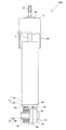
ショックアブソーバ100は、図1に示すように、作動液としての作動油が封入されるアウターケース1と、アウターケース1の一端から延出するピストンロッド2と、一端がピストンロッド2の先端側に固定されるアウターカバー3と、アウターケース1に接合される取付部材としての取付アイ4と、取付アイ4に圧入されるブッシュ5と、を備える。
As shown in FIG. 1, the
アウターケース1は、円筒状のチューブ1aと、チューブ1aのピストンロッド2とは反対側の端部を閉塞するキャップ部材1bと、を備える。キャップ部材1bは、チューブ1aにシーム溶接、プロジェクション溶接等で接合される。なお、アウターケース1は、キャップ部材1bを備えずに、チューブ1aの端部をクロージング加工で閉塞させて形成してもよい。
The
アウターケース1には、作動油が封入されるほか、作動油のキャビテーション防止等のために圧縮気体が封入される。なお、作動液として水等のその他の液体を用いてもよい。
The
ショックアブソーバ100は、単筒型であってもよいし、複筒型であってもよい。ショックアブソーバ100が単筒型である場合は、チューブ1aはシリンダとされる。また、ショックアブソーバ100が複筒型である場合は、チューブ1aはアウターチューブとされる。
The
ピストンロッド2は、アウターケース1に進退自在に挿入される。ピストンロッド2におけるアウターケース1から延出する側の端部には、ショックアブソーバ100を車体側に取り付けるためのおねじ2aが形成される。
The
アウターカバー3は、ピストンロッド2の先端側に溶接等で固定される。アウターカバー3は、具体的には、ピストンロッド2に固定される底部3aと、底部3aからアウターケース1側に向かって形成される筒部3bと、を有する。
The
本実施形態では、アウターカバー3は、底部3aと筒部3bとが一体に成形されている。アウターカバー3の構造は、例えば、底部3aとしての円盤状部材に、筒部3bとしての筒状部材を溶接、圧入等で固定する構造としてもよい。
In the present embodiment, the
取付アイ4は、円筒状であって、被接合部材としてのアウターケース1に、プロジェクション溶接等で外周面4eが接合される。具体的には、取付アイ4は、キャップ部材1bに接合される。また、取付アイ4の接合部4aには、補強溶接6a、6bが施される。これについては後述する。
The mounting
なお、アウターケース1が、上述したクロージング加工により形成されている場合は、取付アイ4は、チューブ1aの加工部に直接接合される。
In addition, when the
ブッシュ5は、ショックアブソーバ100を車軸側に取り付けるためのボルト(図示せず)が挿通される内筒5aと、内筒5aに加硫接着されたゴム部5bと、を備える。なお、ブッシュとしては、例えば、ボールジョイントブッシュを用いてもよい。
The
続いて、取付アイ4の接合部4aに施される補強溶接6a、6bについて説明する。
Next, the
取付アイ4の接合部4aには、図1及び図2に示すように、取付アイ4の軸方向側、すなわち、取付アイ4の端面4f側から補強溶接6aが施され、また、取付アイ4の軸方向と直交する側、すなわち、取付アイ4の外周面4e側から補強溶接6bが施される。補強溶接6a、6bは、例えば、アーク溶接等により施される。
As shown in FIG. 1 and FIG. 2,
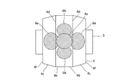
本実施形態では、補強溶接6aは、図3に示すように、接合部4aにおける取付アイ4の両端面4f側に施され、補強溶接6bは、接合部4aにおける取付アイ4の両外周面4e側に施される。このように、ショックアブソーバ100においては、接合部4aにおける取付アイ4の両端面4f側及び両外周面4e側の4か所に補強溶接6a、6bを施すことで、接合部4aの強度を向上させている。
In this embodiment, as shown in FIG. 3, the
なお、補強溶接6aは、取付アイ4の接合部4aに要求される強度によっては、いずれか一方の端面4f側のみに施してもよい。補強溶接6bについても同様である。また、補強溶接6a、6bのいずれかのみを施すようにしてもよい。
The
ところで、補強溶接6bについては、取付アイ4の外周面4eとキャップ部材1bとの間の空間が大きく、容易に施すことができる。一方で、補強溶接6aについては、例えば、取付アイの外周面が全幅で均等な円筒形状である場合は、取付アイの外周面とキャップ部材1bとの間の空間が小さく、溶接が難しい。
By the way, about the
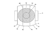
これに対して、本実施形態では、図2に示すように、中央部4bの外径D1よりも端面4f側の外径D2が小さくなるように、取付アイ4が形成されている。具体的には、取付アイ4は、両端部に、中央部4b側から端面4f側に向かって外径が小さくなるテーパ部4cを有する。
On the other hand, in this embodiment, as shown in FIG. 2, the mounting
これによれば、接合部4aにおける取付アイ4の端面4f側の空間が広くなるので、補強溶接6aを容易に施すことができる。また、補強溶接6aのビードが収まる空間を確保できるので、取付アイ4の内周面までビードがはみ出してしまうことを防止できる。
According to this, since the space on the
また、取付アイ4のテーパ部4cは、図3に示すように、接合部4a側の起点4dが、接合部4aよりも端面4f側に設けられており、テーパ部4cと接合部4aとが重ならないようになっている。
Further, as shown in FIG. 3, the
つまり、本実施形態では、取付アイ4が、外周面4eにおける均等な円筒形状部分を用いてアウターケース1に接合されるようになっている。よって、取付アイ4の接合を安定して行うことができる。
That is, in the present embodiment, the mounting
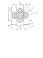
上記実施形態では、接合部4aにおける取付アイ4の両端面4f側及び両外周面4e側の4か所に補強溶接6a、6bを施しているが、図4に示すように、接合部4aの全周に補強溶接6cを施してもよい。
In the above-described embodiment, the reinforcement welds 6a and 6b are applied to the four locations on the both ends 4f side and the both outer
また、取付アイの形状は、例えば、図5に示す取付アイ7のように、両端部に、中央部7bの外径よりも外径が小さい小径部7cを設けた形状としてもよい。
The shape of the mounting eye may be a shape in which, for example, a
これによれば、取付アイ4をアウターケース1に接合した場合と同様に、接合部7aにおける取付アイ7の端面7f側の空間が広くなるので、補強溶接6aを容易に施すことができる。また、補強溶接6aのビードが収まる空間を確保できるので、取付アイ7の内周面までビードがはみ出してしまうことを防止できる。
According to this, similarly to the case where the
取付アイ7の小径部7cは、接合部7a側の起点7dが、接合部7aよりも端面7f側に設けられており、小径部7cと接合部7aとが重ならないようになっている。
The small-
つまり、取付アイ7が、外周面7eにおける均等な円筒形状部分を用いてアウターケース1に接合されるようになっている。よって、取付アイ7の接合を安定して行うことができる。
That is, the mounting
また、上記実施形態では、アウターケース1の端部に取付アイ4を設けているが、図6に示すショックアブソーバ200のように、ピストンロッド2の端部に取付アイ4を設けてもよい。また、ショックアブソーバ100の両端、つまり、アウターケース1の端部とピストンロッド2の端部との両方に、取付アイ4をそれぞれ設けてもよい。
Moreover, in the said embodiment, although the
以下、本発明の実施形態の構成、作用、及び効果をまとめて説明する。 Hereinafter, the configuration, operation, and effect of the embodiment of the present invention will be described together.
ショックアブソーバ100は、一端又は両端に、中央部4b、7bの外径よりも端面4f、7f側の外径が小さい円筒状の取付アイ4、7が外周面4e、7eを接合して設けられ、取付アイ4、7の接合部4a、7aにおける取付アイ4、7の端面4f、7f側に、補強溶接6a、6cが施されてなることを特徴とする。
The
また、取付アイ4は、両端部に、中央部4b側から端面4f側に向かって外径が小さくなるテーパ部4cを有することを特徴とする。
Further, the mounting
また、取付アイ7は、両端部に、中央部7bの外径よりも外径が小さい小径部7cを有することを特徴とする。
The mounting
これらの構成では、取付アイ4、7の端面4f、7f側の外径が中央部4b、7bの外径よりも小さいので、接合部4a、7aにおける取付アイ4、7の端面4f、7f側の空間が広くなる。よって、接合部4a、7aにおける取付アイ4、7の端面4f、7f側に、補強溶接6a、6cを容易に施すことができる。また、補強溶接6a、6cのビードが収まる空間を確保できるので、取付アイ4、7の内周面までビードがはみ出してしまうことを防止できる。
In these configurations, since the outer diameter of the
また、取付アイ4のテーパ部4cにおける接合部4a側の起点4dは、接合部4aよりも端面4f側に設けられることを特徴とする。
Further, the
また、取付アイ7の小径部7cにおける接合部7a側の起点7dは、接合部7aよりも端面7f側に設けられることを特徴とする。
Further, the
これらの構成では、取付アイ4、7が、外周面4e、7eにおける均等な円筒形状部分を用いてショックアブソーバ100に接合される。よって、取付アイ4、7の接合を安定して行うことができる。
In these configurations, the mounting
また、補強溶接6aは、接合部4a、7aにおける取付アイ4、7の両端面4f、7f側及び両外周面4e、7e側の4か所に施されることを特徴とする。
Further, the
この構成では、補強溶接6a、6bが接合部4a、7aの4か所に施されるので、接合部4a、7aの強度が向上する。
In this configuration, since the reinforcement welds 6a and 6b are applied to the four portions of the
また、補強溶接6cは、接合部4a、7aの全周に施されることを特徴とする。
Further, the reinforcement welding 6c is characterized in that it is applied to the entire circumference of the
この構成では、補強溶接6cが接合部4a、7aの全周に施されるので、接合部4a、7aの強度が向上する。
In this structure, since the reinforcement welding 6c is performed to the perimeter of the
以上、本発明の実施形態について説明したが、上記実施形態は本発明の適用例の一部を示したものに過ぎず、本発明の技術的範囲を上記実施形態の具体例に限定する趣旨ではない。 As mentioned above, although embodiment of this invention was described, the said embodiment is only what showed a part of application example of this invention, and in the meaning which limits the technical scope of this invention to the specific example of said embodiment. Absent.
例えば、上記実施形態では、取付アイ4がテーパ部4cを有し、取付アイ7が小径部7cを有しているが、取付アイの形状は、一方の端部にテーパ部を設け、他方の端部に小径部を設けた形状としてもよい。
For example, in the above embodiment, the mounting
また、取付アイの端部の形状は、例えば、中央部側から端面側に向かってテーパ部の途中で小径部に変化する形状としてもよいし、小径部の途中でテーパ部に変化する形状としてもよい。 Further, the shape of the end portion of the mounting eye may be, for example, a shape that changes from the central portion side to the end face side to the small diameter portion in the middle of the taper portion, or a shape that changes to the taper portion in the middle of the small diameter portion. Also good.
100・・・ショックアブソーバ、200・・・ショックアブソーバ、4・・・取付アイ(取付部材)、4a・・・接合部、4b・・・中央部、4c・・・テーパ部、4d・・・起点、4e・・・外周面、4f・・・端面、6a・・・補強溶接、6b・・・補強溶接、6c・・・補強溶接、7・・・取付アイ、7a・・・接合部、7b・・・中央部、7c・・・小径部、7d・・・起点、7e・・・外周面、7f・・・端面
DESCRIPTION OF
Claims (9)
一端又は両端に、金属製であって中央部の外径よりも端面側の外径が小さい円筒状の取付アイが外周面を接合して設けられ、
前記取付アイの接合部における前記取付アイの前記端面側に、補強溶接が施されてなる、
ことを特徴とするショックアブソーバ。 A shock absorber,
At one or both ends, a cylindrical mounting eye made of metal and having a smaller outer diameter on the end surface side than the outer diameter of the central portion is provided by joining the outer peripheral surface,
Reinforcement welding is performed on the end face side of the mounting eye in the joint portion of the mounting eye .
Shock absorber characterized by that.
一端又は両端に、中央部の外径よりも端面側の外径が小さい円筒状の取付アイが外周面を接合して設けられ、At one or both ends, a cylindrical mounting eye having a smaller outer diameter on the end face side than the outer diameter of the central part is provided by joining the outer peripheral face,
前記取付アイに圧入されるブッシュを備え、A bush that is press-fitted into the mounting eye;
前記取付アイの接合部における前記取付アイの前記端面側に、補強溶接が施されてなる、Reinforcement welding is performed on the end face side of the mounting eye in the joint portion of the mounting eye.
ことを特徴とするショックアブソーバ。Shock absorber characterized by that.
前記取付アイは、両端部に、前記中央部側から前記端面側に向かって外径が小さくなるテーパ部を有する、The attachment eye has tapered portions at both ends, the outer diameter of which decreases from the central portion side toward the end face side.
ことを特徴とするショックアブソーバ。Shock absorber characterized by that.
前記取付アイは、両端部に、前記中央部の外径よりも外径が小さい小径部を有する、The mounting eye has a small diameter portion at both ends, the outer diameter of which is smaller than the outer diameter of the central portion.
ことを特徴とするショックアブソーバ。Shock absorber characterized by that.
前記テーパ部における前記接合部側の起点は、前記接合部よりも前記端面側に設けられる、The starting point of the tapered portion on the side of the joint is provided on the end face side of the joint,
ことを特徴とするショックアブソーバ。Shock absorber characterized by that.
前記小径部における前記接合部側の起点は、前記接合部よりも前記端面側に設けられる、The starting point on the joint portion side in the small diameter portion is provided closer to the end face than the joint portion.
ことを特徴とするショックアブソーバ。Shock absorber characterized by that.
前記補強溶接は、前記接合部における前記取付アイの両前記端面側及び両前記外周面側の4か所に施される、The reinforcement welding is performed at four locations on both the end face side and both the outer peripheral face sides of the mounting eye in the joint.
ことを特徴とするショックアブソーバ。Shock absorber characterized by that.
前記補強溶接は、前記接合部の全周に施される、The reinforcement welding is performed on the entire circumference of the joint portion.
ことを特徴とするショックアブソーバ。Shock absorber characterized by that.
前記接合部における前記取付アイの両前記端面側の2か所に施される前記補強溶接は、前記取付アイの周方向において同じ位置に設けられる、The reinforcement welding performed at two locations on both end face sides of the mounting eye at the joint is provided at the same position in the circumferential direction of the mounting eye.
ことを特徴とするショックアブソーバ。Shock absorber characterized by that.
Priority Applications (8)
| Application Number | Priority Date | Filing Date | Title |
|---|---|---|---|
| JP2015005239A JP6445873B2 (en) | 2015-01-14 | 2015-01-14 | shock absorber |
| NZ734391A NZ734391B2 (en) | 2015-01-14 | 2015-11-17 | Shock absorber |
| AU2015377575A AU2015377575B2 (en) | 2015-01-14 | 2015-11-17 | Shock absorber |
| PCT/JP2015/082263 WO2016113996A1 (en) | 2015-01-14 | 2015-11-17 | Shock absorber |
| BR112017013747-0A BR112017013747B1 (en) | 2015-01-14 | 2015-11-17 | SHOCK ABSORBER |
| US15/542,740 US10400850B2 (en) | 2015-01-14 | 2015-11-17 | Shock absorber |
| CA2970862A CA2970862C (en) | 2015-01-14 | 2015-11-17 | Shock absorber |
| MYPI2017702256A MY190578A (en) | 2015-01-14 | 2015-11-17 | Shock absorber |
Applications Claiming Priority (1)
| Application Number | Priority Date | Filing Date | Title |
|---|---|---|---|
| JP2015005239A JP6445873B2 (en) | 2015-01-14 | 2015-01-14 | shock absorber |
Publications (2)
| Publication Number | Publication Date |
|---|---|
| JP2016130565A JP2016130565A (en) | 2016-07-21 |
| JP6445873B2 true JP6445873B2 (en) | 2018-12-26 |
Family
ID=56405553
Family Applications (1)
| Application Number | Title | Priority Date | Filing Date |
|---|---|---|---|
| JP2015005239A Active JP6445873B2 (en) | 2015-01-14 | 2015-01-14 | shock absorber |
Country Status (7)
| Country | Link |
|---|---|
| US (1) | US10400850B2 (en) |
| JP (1) | JP6445873B2 (en) |
| AU (1) | AU2015377575B2 (en) |
| BR (1) | BR112017013747B1 (en) |
| CA (1) | CA2970862C (en) |
| MY (1) | MY190578A (en) |
| WO (1) | WO2016113996A1 (en) |
Families Citing this family (1)
| Publication number | Priority date | Publication date | Assignee | Title |
|---|---|---|---|---|
| JP6657048B2 (en) * | 2016-09-30 | 2020-03-04 | 本田技研工業株式会社 | Processing result abnormality detection device, processing result abnormality detection program, processing result abnormality detection method, and moving object |
Family Cites Families (10)
| Publication number | Priority date | Publication date | Assignee | Title |
|---|---|---|---|---|
| DE3346665A1 (en) * | 1983-12-23 | 1985-07-04 | Lemförder Metallwaren AG, 2844 Lemförde | ELASTIC BEARING WITH FORCED GUIDE |
| DE4420134C1 (en) * | 1994-06-09 | 1995-10-05 | Fichtel & Sachs Ag | Oscillation damper with mechanical traction stop |
| JP3532638B2 (en) * | 1994-11-01 | 2004-05-31 | 株式会社日立ユニシアオートモティブ | Mounting ring for hydraulic shock absorber |
| JPH08261272A (en) * | 1995-03-22 | 1996-10-08 | Keiaishiya Mikami Seisakusho:Kk | Method for manufacturing shock absorber joint and structure of shock absorber joint |
| JP3770458B2 (en) * | 2000-02-22 | 2006-04-26 | 株式会社ショーワ | Hydraulic shock absorber dust cover mounting structure |
| US6981578B2 (en) * | 2003-07-31 | 2006-01-03 | Troy Leiphart | Non-pressurized monotube shock absorber |
| JP4092274B2 (en) * | 2003-09-08 | 2008-05-28 | カヤバ工業株式会社 | Hydraulic shock absorber mounting |
| JP2005083455A (en) * | 2003-09-08 | 2005-03-31 | Kayaba Ind Co Ltd | Hydraulic shock absorber mounting |
| DE102005008045B3 (en) * | 2005-02-23 | 2006-06-08 | Zf Friedrichshafen Ag | Piston cylinder unit e.g. vibration damper, has protection tube with base in which passage opening is conducted and twisted in its axial end position for connection unit e.g. ring bearing, where tube and base are formed from single piece |
| DE102005043234B4 (en) * | 2005-09-09 | 2017-05-11 | Boge Elastmetall Gmbh | Method of making an elastomeric bushing bearing |
-
2015
- 2015-01-14 JP JP2015005239A patent/JP6445873B2/en active Active
- 2015-11-17 CA CA2970862A patent/CA2970862C/en active Active
- 2015-11-17 US US15/542,740 patent/US10400850B2/en active Active
- 2015-11-17 AU AU2015377575A patent/AU2015377575B2/en active Active
- 2015-11-17 MY MYPI2017702256A patent/MY190578A/en unknown
- 2015-11-17 BR BR112017013747-0A patent/BR112017013747B1/en active IP Right Grant
- 2015-11-17 WO PCT/JP2015/082263 patent/WO2016113996A1/en not_active Ceased
Also Published As
| Publication number | Publication date |
|---|---|
| NZ734391A (en) | 2021-01-29 |
| AU2015377575A1 (en) | 2017-08-24 |
| JP2016130565A (en) | 2016-07-21 |
| US20180003261A1 (en) | 2018-01-04 |
| BR112017013747B1 (en) | 2023-11-14 |
| MY190578A (en) | 2022-04-27 |
| WO2016113996A1 (en) | 2016-07-21 |
| CA2970862C (en) | 2023-10-31 |
| BR112017013747A2 (en) | 2018-03-13 |
| US10400850B2 (en) | 2019-09-03 |
| CA2970862A1 (en) | 2016-07-21 |
| AU2015377575B2 (en) | 2019-05-23 |
Similar Documents
| Publication | Publication Date | Title |
|---|---|---|
| JP2019506328A (en) | Hybrid suspension arm for vehicle and manufacturing method thereof | |
| JP6445873B2 (en) | shock absorber | |
| WO2014157467A1 (en) | Joined body | |
| JP2018090245A (en) | Stabilizer for vehicle suspension | |
| JP4996935B2 (en) | Stopper | |
| CN102478092A (en) | Anti-vibration connecting rod | |
| JP2000161414A (en) | Suspension strut | |
| JPWO2018043248A1 (en) | Method of manufacturing stabilizer, and joint structure of stabilizer link | |
| WO2011036890A1 (en) | Torque rod | |
| JP7340000B2 (en) | buffer | |
| NZ734391B2 (en) | Shock absorber | |
| JP5013255B2 (en) | Cylinder device and manufacturing method thereof | |
| JP4092271B2 (en) | Hydraulic shock absorber mounting | |
| CN101131190A (en) | Cylinder device and manufacturing method thereof | |
| CN204437159U (en) | Automotive airbag vibration damper | |
| CN114025973B (en) | Stabilizer | |
| JP6131787B2 (en) | Vehicle suspension arm | |
| JP4913586B2 (en) | Front fork | |
| CN202690851U (en) | Bushing connecting structure for vibration damper | |
| WO2018168216A1 (en) | Accumulator | |
| JP2016114213A (en) | Knuckle bracket and shock absorber | |
| JP2016050608A (en) | Cylinder device | |
| JP4768563B2 (en) | Stopper structure | |
| JP4695458B2 (en) | Strut type shock absorber | |
| CN204437160U (en) | The airbag structure of vibration damper |
Legal Events
| Date | Code | Title | Description |
|---|---|---|---|
| RD02 | Notification of acceptance of power of attorney |
Free format text: JAPANESE INTERMEDIATE CODE: A7422 Effective date: 20161216 |
|
| A521 | Request for written amendment filed |
Free format text: JAPANESE INTERMEDIATE CODE: A523 Effective date: 20170630 |
|
| A711 | Notification of change in applicant |
Free format text: JAPANESE INTERMEDIATE CODE: A711 Effective date: 20170630 |
|
| A521 | Request for written amendment filed |
Free format text: JAPANESE INTERMEDIATE CODE: A821 Effective date: 20170630 |
|
| A621 | Written request for application examination |
Free format text: JAPANESE INTERMEDIATE CODE: A621 Effective date: 20171024 |
|
| A131 | Notification of reasons for refusal |
Free format text: JAPANESE INTERMEDIATE CODE: A131 Effective date: 20180710 |
|
| A521 | Request for written amendment filed |
Free format text: JAPANESE INTERMEDIATE CODE: A523 Effective date: 20180905 |
|
| TRDD | Decision of grant or rejection written | ||
| A01 | Written decision to grant a patent or to grant a registration (utility model) |
Free format text: JAPANESE INTERMEDIATE CODE: A01 Effective date: 20181106 |
|
| A61 | First payment of annual fees (during grant procedure) |
Free format text: JAPANESE INTERMEDIATE CODE: A61 Effective date: 20181130 |
|
| R150 | Certificate of patent or registration of utility model |
Ref document number: 6445873 Country of ref document: JP Free format text: JAPANESE INTERMEDIATE CODE: R150 |
|
| R250 | Receipt of annual fees |
Free format text: JAPANESE INTERMEDIATE CODE: R250 |
|
| R250 | Receipt of annual fees |
Free format text: JAPANESE INTERMEDIATE CODE: R250 |
|
| R250 | Receipt of annual fees |
Free format text: JAPANESE INTERMEDIATE CODE: R250 |
|
| S533 | Written request for registration of change of name |
Free format text: JAPANESE INTERMEDIATE CODE: R313533 |
|
| R350 | Written notification of registration of transfer |
Free format text: JAPANESE INTERMEDIATE CODE: R350 |
|
| R250 | Receipt of annual fees |
Free format text: JAPANESE INTERMEDIATE CODE: R250 |
|
| R250 | Receipt of annual fees |
Free format text: JAPANESE INTERMEDIATE CODE: R250 |