JP6445846B2 - Fastener - Google Patents

Fastener Download PDF

Info

Publication number
JP6445846B2
JP6445846B2 JP2014227413A JP2014227413A JP6445846B2 JP 6445846 B2 JP6445846 B2 JP 6445846B2 JP 2014227413 A JP2014227413 A JP 2014227413A JP 2014227413 A JP2014227413 A JP 2014227413A JP 6445846 B2 JP6445846 B2 JP 6445846B2
Authority
JP
Japan
Prior art keywords
locking
fastener
mounting hole
pair
head
Prior art date
Legal status (The legal status is an assumption and is not a legal conclusion. Google has not performed a legal analysis and makes no representation as to the accuracy of the status listed.)
Active
Application number
JP2014227413A
Other languages
Japanese (ja)
Other versions
JP2016090002A (en
Inventor
米岡 晃
晃 米岡
Current Assignee (The listed assignees may be inaccurate. Google has not performed a legal analysis and makes no representation or warranty as to the accuracy of the list.)
Piolax Inc
Original Assignee
Piolax Inc
Priority date (The priority date is an assumption and is not a legal conclusion. Google has not performed a legal analysis and makes no representation as to the accuracy of the date listed.)
Filing date
Publication date
Application filed by Piolax Inc filed Critical Piolax Inc
Priority to JP2014227413A priority Critical patent/JP6445846B2/en
Publication of JP2016090002A publication Critical patent/JP2016090002A/en
Application granted granted Critical
Publication of JP6445846B2 publication Critical patent/JP6445846B2/en
Active legal-status Critical Current
Anticipated expiration legal-status Critical

Links

Images

Landscapes

  • Insertion Pins And Rivets (AREA)

Description

本発明は、被取付部材の取付孔に留めるための留め具に関する。   The present invention relates to a fastener for fastening in a mounting hole of a member to be attached.

車両の車体パネルに内装パネルや飾り材などを取り付ける場合に、留め具が用いられる(特許文献1参照)。特許文献1に開示される樹脂クリップは、フランジ状の頭部と、頭部から垂下するように延出する支柱と、支柱の先端から頭部に向かって折り返すとともにV字状に広がる一対の弾性脚と、弾性脚の外側に扇形状に形成された段状の係止部とを備える。   A fastener is used when attaching an interior panel or a decoration material to a vehicle body panel of a vehicle (see Patent Document 1). The resin clip disclosed in Patent Document 1 includes a flange-shaped head, a support column extending so as to hang down from the head, and a pair of elasticity that folds back from the tip of the support toward the head and spreads in a V-shape. A leg, and a stepped locking portion formed in a fan shape on the outside of the elastic leg.

特許文献1の樹脂クリップを、パネルの円形状の取付孔に支柱の先端から挿入し、係止部を取付孔の裏縁に当接させることで、係止部と頭部とでパネルを挟み込んで樹脂クリップの取り付けが完了する。   The resin clip of Patent Document 1 is inserted into the circular mounting hole of the panel from the tip of the column, and the locking part is brought into contact with the back edge of the mounting hole, so that the panel is sandwiched between the locking part and the head. This completes the mounting of the resin clip.

特開2002−276633号公報JP 2002-276633 A

特許文献1に開示される技術では、係止部が円形状の取付孔に応じて扇形状に形成されており、四角状の取付孔に取り付けると係止部の掛かり代が小さくなり、外れやすくなる恐れがある。特に、一対の弾性脚が四角状の取付孔の対角線上に位置して、係止部が取付孔の角部に位置する場合に、より外れやすくなる恐れがある。   In the technique disclosed in Patent Document 1, the locking portion is formed in a fan shape in accordance with the circular mounting hole, and when it is attached to the square mounting hole, the locking portion of the locking portion becomes small and is easily detached. There is a fear. In particular, when the pair of elastic legs are positioned on the diagonal line of the square mounting hole and the locking portion is positioned at the corner of the mounting hole, there is a possibility that it will be easier to come off.

本発明はこのような課題に鑑みてなされたものであり、その目的は、円形状の取付孔に取り付けた場合にも、角状の取付孔に取り付けた場合にも、外れにくい留め具を提供することにある。   The present invention has been made in view of such a problem, and the object thereof is to provide a fastener that is difficult to come off whether it is attached to a circular attachment hole or a square attachment hole. There is to do.

上記課題を解決するために、本発明のある態様の留め具は、頭部と、被取付部材の取付孔に挿入される脚部と、を備える。脚部は、頭部の裏面から延出する基部と、基部から頭部側に向かって延出し、撓み可能な一対の弾性係止体と、弾性係止体の先端側に形成され、取付孔の裏縁に係止するための係止部と、係止部より頭部側に向かって突出して、取付孔に入り込む突起部と、を有する。一対の弾性係止体の対向方向の係止部の長さは、両側端部が中央部より長い。   In order to solve the above-described problems, a fastener according to an aspect of the present invention includes a head portion and a leg portion that is inserted into an attachment hole of a member to be attached. The leg portion is formed on a base portion extending from the back surface of the head portion, a pair of elastic locking bodies extending from the base portion toward the head side, and being deflectable, and on a distal end side of the elastic locking body. A locking portion for locking to the back edge of the rim, and a protrusion protruding from the locking portion toward the head and entering the mounting hole. As for the length of the locking portion in the opposing direction of the pair of elastic locking bodies, both end portions are longer than the center portion.

本発明の別の態様は、留め具である。この留め具は、頭部と、被取付部材の取付孔に挿入される脚部と、を備える。脚部は、頭部の裏面から延出する基部と、基部から頭部側に向かって延出し、撓み可能な一対の弾性係止体と、弾性係止体の先端側に形成され、取付孔の裏縁に係止するための係止部と、係止部より頭部側に向かって突出して、取付孔に入り込む突起部と、を有する。突起部は、一対の弾性係止体の外側にテーパ状に形成される。   Another aspect of the present invention is a fastener. The fastener includes a head and a leg that is inserted into the attachment hole of the attached member. The leg portion is formed on a base portion extending from the back surface of the head portion, a pair of elastic locking bodies extending from the base portion toward the head side, and being deflectable, and on a distal end side of the elastic locking body. A locking portion for locking to the back edge of the rim, and a protrusion protruding from the locking portion toward the head and entering the mounting hole. The protrusion is tapered outside the pair of elastic locking bodies.

本発明によれば、円形状の取付孔に取り付けた場合にも、角状の取付孔に取り付けた場合にも、外れにくい留め具を提供できる。   ADVANTAGE OF THE INVENTION According to this invention, even when it attaches to a circular attachment hole and when it attaches to a square attachment hole, the fastener which cannot be removed easily can be provided.

図1(a)および図1(b)は、留め具の斜視図である。Fig.1 (a) and FIG.1 (b) are the perspective views of a fastener. 図1(b)に示す留め具の線分A−Aの断面図である。It is sectional drawing of line segment AA of the fastener shown in FIG.1 (b). 図3(a)は、留め具の平面図であり、図3(b)は、留め具の底面図である。Fig.3 (a) is a top view of a fastener, FIG.3 (b) is a bottom view of a fastener. 留め具の右側面図および左側面図である。It is the right view and left view of a fastener. 留め具の正面図および背面図である。It is the front view and back view of a fastener. 係止部および突起部について説明するための図である。It is a figure for demonstrating an engaging part and a projection part. 留め具の係止面を示す図であり、係止面以外の構成を破線で示す。It is a figure which shows the latching surface of a fastener, and structures other than a latching surface are shown with a broken line. 取付孔に取り付けた状態の留め具を説明するための図である。It is a figure for demonstrating the fastener of the state attached to the attachment hole. 図9(a)は、留め具を角状の第2取付孔の角部に取り付けた状態を示す図であり、図9(b)は、比較技術の留め具第2取付孔の角部に取り付けた状態を示す図である。Fig.9 (a) is a figure which shows the state which attached the fastener to the corner | angular part of the square-shaped 2nd attachment hole, and FIG.9 (b) is a corner | angular part of the fastener 2nd attachment hole of a comparison technique. It is a figure which shows the attached state. 変形例の留め具を説明するための図であり、変形例の脚部の斜視図である。It is a figure for demonstrating the fastener of a modification, and is a perspective view of the leg part of a modification.

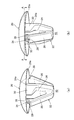
図1(a)および図1(b)は、留め具10の斜視図であって、異なる方向から見た図である。留め具10は、取付部材を被取付部材に取り付けるため、または被取付部材に留めるために用いられる。例えば、留め具10は、車体パネルに内装パネルを取り付けるため、車体パネルにホースやハーネスを固定するため、内装パネルに飾り部品を取り付けるため等に使用される。   Fig.1 (a) and FIG.1 (b) are the perspective views of the fastener 10, Comprising: It is the figure seen from the different direction. The fastener 10 is used for attaching the attachment member to the attached member or for fastening the attachment member to the attached member. For example, the fastener 10 is used for attaching an interior panel to a vehicle body panel, fixing a hose or a harness to the vehicle body panel, attaching a decorative part to the interior panel, and the like.

留め具10は、フランジ状の頭部20と、パネルの取付孔に挿入される脚部22とを備える。頭部20は傘状に形成され、脚部22を取付孔に挿入した場合、頭部20の外周端20aがパネルの表面に当接する。   The fastener 10 includes a flange-shaped head portion 20 and leg portions 22 inserted into the mounting holes of the panel. The head portion 20 is formed in an umbrella shape, and when the leg portion 22 is inserted into the mounting hole, the outer peripheral end 20a of the head portion 20 comes into contact with the surface of the panel.

脚部22は、頭部20の中心から延出する柱部24と、柱部24の先端側から頭部20側に向かって延出する一対の弾性係止体26と、一対の弾性係止体26の対向方向の外側に位置する係止部28と、係止部28より頭部20側に突出する突起部36と、を有する。柱部24は、脚部22において、弾性係止体26を支持する基部として機能する。   The leg portion 22 includes a column portion 24 extending from the center of the head portion 20, a pair of elastic locking bodies 26 extending from the front end side of the column portion 24 toward the head portion 20 side, and a pair of elastic locking portions. It has the latching | locking part 28 located in the outer side of the opposing direction of the body 26, and the projection part 36 which protrudes from the latching | locking part 28 to the head 20 side. The column portion 24 functions as a base portion that supports the elastic locking body 26 in the leg portion 22.

柱部24は壁状に形成され、幅方向の両端24aに湾曲壁部30がそれぞれ形成される。湾曲壁部30は、柱部24の両端24aから周方向に張り出すように形成され、湾曲壁部30の外周面は円形の取付孔に沿って湾曲する。湾曲壁部30により、柱部24の剛性が高まる。湾曲壁部30は、弾性係止体26の撓みを妨げないように、弾性係止体26と柱部24の間に張り出さないように形成される。   The column portion 24 is formed in a wall shape, and the curved wall portions 30 are formed at both ends 24a in the width direction. The curved wall portion 30 is formed so as to protrude from both ends 24a of the column portion 24 in the circumferential direction, and the outer peripheral surface of the curved wall portion 30 is curved along a circular mounting hole. The curved wall portion 30 increases the rigidity of the column portion 24. The curved wall portion 30 is formed so as not to protrude between the elastic locking body 26 and the column portion 24 so as not to hinder the bending of the elastic locking body 26.

一対の弾性係止体26は、柱部24の先端側から頭部20に向かって折り返すように形成され、柱部24を挟んで対向する。一対の弾性係止体26は、対向方向に撓み可能であり、取付孔への挿入時には接近する方向に撓む。なお以下の説明で、対向方向とは、一対の弾性係止体26が対向する方向をいい、一対の弾性係止体26が接近または離間する撓み方向をいう。   The pair of elastic locking bodies 26 are formed so as to be folded back from the distal end side of the column portion 24 toward the head portion 20 and face each other with the column portion 24 interposed therebetween. The pair of elastic locking bodies 26 can be bent in the facing direction, and bend in the approaching direction when inserted into the attachment hole. In the following description, the facing direction refers to the direction in which the pair of elastic locking bodies 26 face each other, and refers to the bending direction in which the pair of elastic locking bodies 26 approach or separate.

係止部28は、弾性係止体26の先端側に台状に形成され、取付完了状態で取付孔の裏縁に当接して係止する。係止部28は、突起部36より対向方向外側に位置する。係止部28は、係止面32および傾斜面34を有する。係止面32は、傾斜面34より対向方向の外側に位置し、傾斜面34と対向方向に連なって形成される。傾斜面34は、係止面32より弾性係止体26の先端側に位置し、係止面32に対して傾斜する。パネルの板厚によっては、傾斜面34が取付孔の裏縁に当接して係止する。   The locking portion 28 is formed in a trapezoidal shape on the distal end side of the elastic locking body 26 and locks by contacting the back edge of the mounting hole when the mounting is completed. The locking portion 28 is located on the outer side in the opposite direction from the protruding portion 36. The locking portion 28 has a locking surface 32 and an inclined surface 34. The locking surface 32 is located outside the inclined surface 34 in the opposite direction, and is formed continuously with the inclined surface 34 in the opposite direction. The inclined surface 34 is located closer to the distal end side of the elastic locking body 26 than the locking surface 32 and is inclined with respect to the locking surface 32. Depending on the thickness of the panel, the inclined surface 34 comes into contact with the back edge of the mounting hole and is locked.

突起部36は、弾性係止体26の先端に略三角柱状に形成され、係止部28に連設して係止部28より頭部20側に突出する。突起部36は、取付完了状態で取付孔の内側に入り込み、留め具10に対してパネルの表面に沿う方向への力が作用した場合でも、係止部28の取付孔の縁への係止が外れることを抑える。実施形態の留め具10は、角状の取付孔であっても、円形状の取付孔であっても取り付けられるように構成されている。この留め具10の各構成について以下の図面を参照しつつ詳細に説明する。   The protruding portion 36 is formed in a substantially triangular prism shape at the tip of the elastic locking body 26, is provided continuously with the locking portion 28, and protrudes from the locking portion 28 toward the head 20. The protrusion 36 enters the inside of the attachment hole when the attachment is completed, and even when a force in a direction along the surface of the panel is applied to the fastener 10, the engagement portion 28 is locked to the edge of the attachment hole. To prevent it from coming off. The fastener 10 according to the embodiment is configured to be attached to a square attachment hole or a circular attachment hole. Each configuration of the fastener 10 will be described in detail with reference to the following drawings.

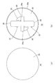
図2は、図1(b)に示す留め具10の線分A−Aの断面図である。図3(a)は、留め具10の平面図であり、図3(b)は、留め具10の底面図である。図4は、留め具10の右側面図および左側面図である。図5は、留め具10の正面図および背面図である。ここで各図面に示される同一または同等の構成要素、部材には、同一の符号を付するものとし、適宜重複した説明は省略する。   FIG. 2 is a cross-sectional view taken along line AA of the fastener 10 shown in FIG. 3A is a plan view of the fastener 10, and FIG. 3B is a bottom view of the fastener 10. FIG. 4 is a right side view and a left side view of the fastener 10. FIG. 5 is a front view and a rear view of the fastener 10. Here, the same or equivalent components and members shown in the drawings are denoted by the same reference numerals, and repeated description thereof is omitted as appropriate.

図2および図3(b)に示すように、湾曲壁部30は周方向に湾曲して、断面の外周は円弧状に形成される。自由状態での一対の弾性係止体26は、柱部24の両端24aより、すなわち柱部24の外接円より径方向外側に張り出す。壁状の柱部24は、弾性係止体26の対向方向には幅方向より薄く形成される。これにより、弾性係止体26の撓み可能な間隔を大きくできる。湾曲壁部30を湾曲して形成することで、円形状だけでなく角状の取付孔内で柱部24が回転可能になる。図3(b)に示すように、弾性係止体26の対向方向外側の面は、湾曲した曲面に形成される。   As shown in FIGS. 2 and 3B, the curved wall 30 is curved in the circumferential direction, and the outer periphery of the cross section is formed in an arc shape. The pair of elastic locking bodies 26 in a free state protrudes outward in the radial direction from both ends 24 a of the column part 24, that is, from the circumscribed circle of the column part 24. The wall-shaped column portion 24 is formed thinner than the width direction in the opposing direction of the elastic locking body 26. Thereby, the space | interval in which the elastic latching body 26 can be bent can be enlarged. By forming the curved wall portion 30 to be curved, the column portion 24 can be rotated not only in a circular shape but also in a square mounting hole. As shown in FIG. 3B, the surface on the outer side in the opposing direction of the elastic locking body 26 is formed as a curved curved surface.

図4および図5に示すように、留め具10は中心軸に対して対称形状に形成され、右側面図および左側面図は同じであり、正面図および背面図も同じである。図5に示すように、一対の弾性係止体26は、柱部24の先端24b側から頭部20側に向かって拡開して、略V字状に形成される。図5に示すように、係止部28に傾斜面34を設けることで、パネルの板厚変化に対応できる。すなわち、板厚が厚い場合は、係止面32が取付孔の裏縁に当接し、板厚が薄い場合は、傾斜面34が取付孔の裏縁に当接して、留め具10がパネルに取付られる。   As shown in FIGS. 4 and 5, the fastener 10 is formed symmetrically with respect to the central axis, the right side view and the left side view are the same, and the front view and the rear view are also the same. As shown in FIG. 5, the pair of elastic locking bodies 26 expands from the tip 24 b side of the column part 24 toward the head 20 side, and is formed in a substantially V shape. As shown in FIG. 5, by providing the inclined surface 34 in the locking portion 28, it is possible to cope with a change in the panel thickness. That is, when the plate thickness is thick, the locking surface 32 comes into contact with the back edge of the mounting hole, and when the plate thickness is thin, the inclined surface 34 comes into contact with the back edge of the mounting hole and the fastener 10 is attached to the panel. Attached.

図2に示すように、傾斜面34は、第1傾斜面34a、第2傾斜面34bおよび中央傾斜面34cを有する。突起部36は、第1テーパ面36a、第2テーパ面36bおよび中央部36cを有する。傾斜面34および突起部36は、一対の弾性係止体26の外側にテーパ状に尖るように形成される。なお、一対の弾性係止体26が対向する面を内側とし、その逆を外側とする。また、傾斜面34および突起部36は、柱部24の中心軸に対して径方向外向きに、または一対の弾性係止体26の対向方向の外向きにテーパ状に形成される。   As shown in FIG. 2, the inclined surface 34 has a first inclined surface 34a, a second inclined surface 34b, and a central inclined surface 34c. The protrusion 36 has a first tapered surface 36a, a second tapered surface 36b, and a central portion 36c. The inclined surface 34 and the protruding portion 36 are formed so as to be pointed in a tapered shape outside the pair of elastic locking bodies 26. In addition, let the surface where a pair of elastic locking body 26 oppose be an inner side, and let the reverse be an outer side. In addition, the inclined surface 34 and the protruding portion 36 are formed in a tapered shape outward in the radial direction with respect to the central axis of the column portion 24 or outward in the opposing direction of the pair of elastic locking bodies 26.

図2に示すように、対向方向において、係止部28の長さは、対向方向に直交する方向における両側端部28aが中央部28bより長い。また、対向方向において、係止部28の長さは、中央部28b側から両側端部28a側に向かって長くなるように形成される。つまり、係止部28は、中央部28bから両側端部28aに向かって幅広になるように形成される。これにより、取付孔の裏縁への係止部28の掛かり代を両側端部28a側で増やすことができ、係止部28を取付孔から外れにくくできる。   As shown in FIG. 2, in the facing direction, the length of the locking portion 28 is longer at both side end portions 28a in the direction orthogonal to the facing direction than the central portion 28b. Further, in the facing direction, the length of the locking portion 28 is formed so as to increase from the central portion 28b side toward the side end portions 28a side. That is, the locking portion 28 is formed so as to become wider from the central portion 28b toward the both end portions 28a. Thereby, the allowance of the latching | locking part 28 to the back edge of an attachment hole can be increased by the both-ends part 28a side, and the latching | locking part 28 can be made hard to remove | deviate from an attachment hole.

図2に示すように、係止面32も中央部から両側端部に向かって幅広になる形状を有する。傾斜面34は、中央部から両側端部に向かって幅狭になるように形成される。傾斜面34の中央傾斜面34cは、弾性係止体26の外面と同じく曲面に形成される。   As shown in FIG. 2, the locking surface 32 also has a shape that becomes wider from the central portion toward both end portions. The inclined surface 34 is formed so as to become narrower from the central portion toward both end portions. The central inclined surface 34 c of the inclined surface 34 is formed in a curved surface similar to the outer surface of the elastic locking body 26.

図6は、係止部28および突起部36の大きさについて説明するための図である。図6に示す各長さL1〜L7は、いずれも対向方向に沿う。係止部28の両側端部28aの長さL1は、係止部28の中央部28bの長さL4より長い。また、係止面32の両側端部32aの長さL2は、係止面32の中央部32bの長さL5より長い。この長さの関係性により、両側端部32a側を中央部32bより幅広に形成される。   FIG. 6 is a diagram for explaining the sizes of the locking portion 28 and the protruding portion 36. Each length L1-L7 shown in FIG. 6 is along the opposing direction. The length L1 of the both end portions 28a of the locking portion 28 is longer than the length L4 of the central portion 28b of the locking portion 28. Further, the length L2 of the both end portions 32a of the locking surface 32 is longer than the length L5 of the central portion 32b of the locking surface 32. Due to this length relationship, both end portions 32a are formed wider than the central portion 32b.

係止面32の中央部32bの最外端32cと両側端部32aの最内端32dの長さL7は、中央部32bの長さL5の2倍以上となるように設定される。これにより、より両側端部32a側をより幅広にできる。また、長さL7と長さL5との差が、長さL5より大きく、(L7−L5)>L5の式を満たすように係止面32が形成される。これにより、両側端部32a側をよりいっそう幅広にできる。傾斜面34の両側端部34dの長さL3は、傾斜面34の中央傾斜面34cの長さL6より短い。   The length L7 of the outermost end 32c of the central portion 32b of the locking surface 32 and the innermost end 32d of the side end portions 32a is set to be at least twice the length L5 of the central portion 32b. Thereby, the both-side end part 32a side can be made wider. Further, the locking surface 32 is formed so that the difference between the length L7 and the length L5 is larger than the length L5 and satisfies the expression (L7−L5)> L5. Thereby, the both-side end part 32a side can be made still wider. The length L3 of the both end portions 34d of the inclined surface 34 is shorter than the length L6 of the central inclined surface 34c of the inclined surface 34.

図6に示すように、突起部36の第1テーパ面36aと第2テーパ面36bのテーパ角Aは、80度から130度の範囲に収まるように形成される。これにより、四角状の取付孔の角部に突起部36を十分に入り込ませることができる。また、突起部36が尖り過ぎたり、薄くなり過ぎて剛性が低下し過ぎることを抑えられる。   As shown in FIG. 6, the taper angle A of the first taper surface 36a and the second taper surface 36b of the protrusion 36 is formed to fall within the range of 80 degrees to 130 degrees. Thereby, the projection part 36 can fully enter the corner | angular part of a square-shaped attachment hole. Further, it is possible to prevent the protrusion 36 from being too sharp or too thin and the rigidity from being excessively lowered.

図7は、留め具10の係止面32を示す図であり、係止面32以外の構成を破線で示す。図7(a)は、係止面32の右側面図および左側面図であり、図7(b)は、係止面32の正面図および背面図である。係止面32は、中央部32bから両側端部32aに向かって幅広になるように形成される。留め具10の係止面32は意匠的に美観を起こさせる部分である。   FIG. 7 is a diagram illustrating the locking surface 32 of the fastener 10, and components other than the locking surface 32 are indicated by broken lines. FIG. 7A is a right side view and a left side view of the locking surface 32, and FIG. 7B is a front view and a rear view of the locking surface 32. The locking surface 32 is formed so as to become wider from the central portion 32b toward the both end portions 32a. The locking surface 32 of the fastener 10 is a part that aesthetically enhances the design.

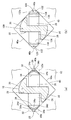
図8は、取付孔に取り付けた状態の留め具10を説明するための図である。図8(a)は、留め具10を円形状の第1取付孔42に取り付けた状態を示し、図8(b)は、留め具10を角状の第2取付孔40の辺部40aに取り付けた状態を示す。なお、図8(a)および(b)は、頭部20側から脚部22側を見た断面図であり、パネルの取付孔の裏側に張り出した係止部28の一部は破線で示す。   FIG. 8 is a view for explaining the fastener 10 in a state of being attached to the attachment hole. FIG. 8A shows a state in which the fastener 10 is attached to the circular first attachment hole 42, and FIG. 8B shows the fastener 10 on the side portion 40 a of the square second attachment hole 40. The attached state is shown. 8A and 8B are cross-sectional views of the leg portion 22 side as viewed from the head 20 side, and a part of the locking portion 28 protruding to the back side of the mounting hole of the panel is indicated by a broken line. .

一対の係止部28の対向方向の最外間隔、すなわち自由状態の係止部28の外接円の直径が大きくなるほど、取付孔への挿入性が低下するが、一方で、係止部28の面積を大きくすることができ、抜けにくくできる。挿入性や弾性係止体26の撓み性能によって、一対の係止部28の最外間隔は絞られる。その制約の中で、実施形態の係止部28を中央部28bから両側端部28aに向かって幅広にすることで、角状および円形状の取付孔にそれぞれ十分に係止させることが可能となる。   As the outermost interval in the opposing direction of the pair of locking portions 28, that is, the diameter of the circumscribed circle of the locking portions 28 in the free state increases, the insertability into the mounting hole decreases. The area can be increased and it is difficult to remove. The outermost distance between the pair of locking portions 28 is narrowed by the insertability and the bending performance of the elastic locking body 26. Within that restriction, the locking portion 28 of the embodiment is made wider from the central portion 28b toward the both side end portions 28a, so that it can be sufficiently locked in the square and circular mounting holes, respectively. Become.

図8(a)に示すように、第1パネル14に円形状の第1取付孔42が形成され、第1取付孔42に脚部22が挿入されている。一対の弾性係止体26は、接近する方向に撓み、対向方向外向きに付勢する。これにより、第1取付孔42の縁に中央傾斜面34cが当接し、係止面32が第1取付孔42の裏縁に張り出して、係止部28が係止する。第1パネル14に対する係止面32の掛かり代が、両側端側を幅広形状にすることで十分に確保されている。また、突起部36が第1取付孔42の内側に入り込むことで係止部28が第1取付孔42の裏縁から外れることを抑えることができる。   As shown in FIG. 8A, a circular first mounting hole 42 is formed in the first panel 14, and the leg portion 22 is inserted into the first mounting hole 42. The pair of elastic locking bodies 26 bend in the approaching direction and urge outward in the facing direction. As a result, the central inclined surface 34 c comes into contact with the edge of the first mounting hole 42, the locking surface 32 protrudes from the back edge of the first mounting hole 42, and the locking portion 28 is locked. Engagement of the locking surface 32 with respect to the first panel 14 is sufficiently ensured by making both side ends wide. In addition, it is possible to prevent the locking portion 28 from coming off the back edge of the first mounting hole 42 by the protrusion 36 entering the inside of the first mounting hole 42.

図8(b)に示すように、第2パネル12に角状の第2取付孔40が形成され、第2取付孔40に脚部22が挿入されている。係止部28は、中央傾斜面34cを第2取付孔40の辺部40aに当接させて係止する。図8(b)に示すように第2パネル12に対する係止面32の掛かり代は、十分に確保されている。このように、円形状の第1取付孔42にも、角状の第2取付孔40にも十分に係止部28を係止させることができる。   As shown in FIG. 8B, a square-shaped second mounting hole 40 is formed in the second panel 12, and the leg portion 22 is inserted into the second mounting hole 40. The locking portion 28 is locked by bringing the central inclined surface 34 c into contact with the side portion 40 a of the second mounting hole 40. As shown in FIG. 8 (b), the allowance for the locking surface 32 to the second panel 12 is sufficiently secured. As described above, the locking portion 28 can be sufficiently locked to both the circular first mounting hole 42 and the square second mounting hole 40.

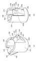
図9(a)は、留め具10を角状の第2取付孔40の角部40bに取り付けた状態を示し、図9(b)は、比較技術の留め具100第2取付孔40の角部40bに取り付けた状態を示す。   9A shows a state in which the fastener 10 is attached to the corner portion 40b of the square-shaped second attachment hole 40, and FIG. 9B shows a corner of the fastener 100 second attachment hole 40 of the comparative technique. The state attached to the part 40b is shown.

留め具10は、柱部24および湾曲壁部30の外周の湾曲形状により、四角状の第2取付孔40内でも回転可能である。図9(a)に示す留め具10は、図8(b)に示した留め具10が45度軸回転して、辺部40a中央に係止していた係止部28が、第2取付孔40の角部40bに係止している。一対の弾性係止体26が対角線上に位置する場合、第2取付孔40の縁に中央傾斜面34cは当接せず、第1傾斜面34aおよび第2傾斜面34bの両側端部が当接し、係止面32が第2取付孔40の裏縁に張り出して、係止部28が角部40bに係止した状態になる。一対の弾性係止体26は、第2取付孔40の対角線上に位置することで、対向間隔が長くなり、係止部28が辺部40a中央に係止する状態より拡開する。   The fastener 10 can also rotate within the square second mounting hole 40 due to the curved shape of the outer periphery of the column part 24 and the curved wall part 30. The fastener 10 shown in FIG. 9 (a) has the second attachment portion of the latching portion 28, which has been pivoted 45 degrees around the fastener 10 shown in FIG. The hole 40 is locked to the corner 40b. When the pair of elastic locking bodies 26 are located diagonally, the central inclined surface 34c does not contact the edge of the second mounting hole 40, and both end portions of the first inclined surface 34a and the second inclined surface 34b are in contact with each other. The locking surface 32 protrudes from the back edge of the second mounting hole 40 and the locking portion 28 is locked to the corner portion 40b. Since the pair of elastic locking bodies 26 are positioned on the diagonal line of the second mounting hole 40, the facing interval becomes longer, and the locking portion 28 expands than the state where the locking portion 28 is locked at the center of the side portion 40a.

弾性係止体26が対角線上に位置した状態では、傾斜面34および突起部36が対向方向外向きにテーパ状に形成されるため、角部40bに入り込み、係止部28の掛かり代が十分に確保できる。   In the state where the elastic locking body 26 is positioned diagonally, the inclined surface 34 and the projection 36 are tapered outward in the facing direction, so that the corner 40b enters and the locking portion 28 has a sufficient allowance. Can be secured.

図9(b)に示す比較技術の留め具100は、円形状の第1取付孔42に用いるものであって、図9(a)に示す留め具10と比べて、係止部の形状および突起部の形状が異なる。図9(b)に示す留め具100は、係止面132および傾斜面134は、同じ幅の扇形状であり、突起部136の外面は第1取付孔42の内周面に沿って湾曲して形成される。   The fastener 100 of the comparative technique shown in FIG. 9B is used for the first mounting hole 42 having a circular shape, and compared with the fastener 10 shown in FIG. The shape of the protrusion is different. In the fastener 100 shown in FIG. 9B, the locking surface 132 and the inclined surface 134 are fan-shaped with the same width, and the outer surface of the protrusion 136 is curved along the inner peripheral surface of the first mounting hole 42. Formed.

図9(b)に示すように、係止面132が第2パネル12の裏側に部分的に張り出しているものの、傾斜面134または突起部136が辺部40aに引っかかり、係止部128の掛かり代は少ない。これは、係止面132の両側端部132aの長さが、図9(a)に示す係止面32の両側端部32aより短いためである。   As shown in FIG. 9B, although the locking surface 132 partially protrudes from the back side of the second panel 12, the inclined surface 134 or the protrusion 136 is caught by the side portion 40a, and the locking portion 128 is hooked. There is little bill. This is because the length of the both side end portions 132a of the locking surface 132 is shorter than the both side end portions 32a of the locking surface 32 shown in FIG.

係止部28が角部40bに係止する場合、辺部40a中央に係止する場合より、一対の弾性係止体26が対角線上に位置して拡開するため、引っかかり力が低下する。そのため、図9(b)に示す留め具100では、一対の弾性係止体26が拡開して撓み量が少なく、係止部128の掛かり代が少ないため、外れやすい。   When the locking portion 28 is locked to the corner portion 40b, the pair of elastic locking bodies 26 is located on the diagonal line and expands compared to the case where the locking portion 28 is locked to the center of the side portion 40a. For this reason, in the fastener 100 shown in FIG. 9B, the pair of elastic locking bodies 26 expands and the amount of bending is small, and the latching portion 128 has a small allowance, so it is easy to come off.

一方、図9(a)に示す留め具10では、弾性係止体26の撓み量が少ないものの、係止面32の両側端部32aの全てが第1パネル14の裏面に引っ掛かるため、図8(b)に示す辺部40a中央に係止する場合と比べて係止部28の掛かり代が増え、外れにくくできる。これにより、係止部28を図8(b)に示す辺部40aの中央に係止させていても、留め具10が軸回転して角部40bに係止しても、外れにくくできる。   On the other hand, in the fastener 10 shown in FIG. 9 (a), although the amount of bending of the elastic locking body 26 is small, all of the both side end portions 32a of the locking surface 32 are caught on the back surface of the first panel 14. Compared with the case of locking at the center of the side portion 40a shown in FIG. Thereby, even if the latching | locking part 28 is latched in the center of the side part 40a shown in FIG.8 (b), even if the fastener 10 rotates about an axis | shaft and it latches to the corner | angular part 40b, it can become difficult to remove | deviate.

図10は、変形例の留め具を説明するための図であり、変形例の脚部222の斜視図である。脚部222は、円筒状の柱部224と、柱部224の先端側の側面から不図示の頭部側に向かって延出する一対の弾性係止体226と、弾性係止体226の先端側に形成された係止部228と、係止部228より頭部側に突出する突起部236と、を有する。柱部224は、脚部222の基部として機能する。   FIG. 10 is a view for explaining a modified fastener, and is a perspective view of a leg portion 222 of the modified example. The leg portion 222 includes a cylindrical column portion 224, a pair of elastic locking bodies 226 extending from the side surface on the distal end side of the column portion 224 toward the head side (not shown), and the distal ends of the elastic locking bodies 226. It has the latching | locking part 228 formed in the side, and the projection part 236 which protrudes from the latching | locking part 228 to the head side. The column part 224 functions as a base part of the leg part 222.

柱部224の側面には一対のスリット238が軸方向に沿って形成され、スリット238の下端に弾性係止体226が撓み可能に連結される。弾性係止体226は頭部側に向かうに従って径方向外向きに張り出すように形成される。   A pair of slits 238 are formed on the side surface of the column portion 224 along the axial direction, and an elastic locking body 226 is flexibly connected to the lower end of the slit 238. The elastic locking body 226 is formed so as to project outward in the radial direction toward the head side.

係止部228は、台状の係止面232と、係止面232に対して傾斜する傾斜面234を有する。係止部228は、突起部236より径方向外側に位置する。対向方向の係止部228の長さは、両側端部228aが中央部228bより長い。また、対向方向の係止部228の長さは、中央部228b側から両側端部228a側に向かって長くなるように形成される。つまり、係止部228は、中央部228bから両側端部228aに向かって幅広になるように形成される。これにより、角状の取付孔でも、円形状の取付孔に取り付けても係止部228を外れにくくできる。   The locking portion 228 has a trapezoidal locking surface 232 and an inclined surface 234 that is inclined with respect to the locking surface 232. The locking portion 228 is located on the outer side in the radial direction than the protruding portion 236. As for the length of the engaging portion 228 in the facing direction, both side end portions 228a are longer than the central portion 228b. Further, the length of the engaging portion 228 in the facing direction is formed so as to increase from the center portion 228b side toward the both end portions 228a side. That is, the locking portion 228 is formed so as to become wider from the central portion 228b toward the both end portions 228a. Thereby, even if it attaches to a square attachment hole or a circular attachment hole, the latching | locking part 228 can be made hard to remove | deviate.

突起部236および傾斜面234は、対向方向外向き、すなわち径方向外向きにテーパ状に尖るように形成される。これにより、突起部236および傾斜面234が角状の第2取付孔40の角部40bに入り込むことができ、留め具10が軸回転して角部40bに係止しても、第2取付孔40から外れにくくできる。   The protruding portion 236 and the inclined surface 234 are formed so as to be tapered outward in the opposing direction, that is, radially outward. As a result, the protrusion 236 and the inclined surface 234 can enter the corner 40b of the square second mounting hole 40, and even if the fastener 10 is pivoted and locked to the corner 40b, the second mounting is performed. It can be difficult to come off from the hole 40.

なお、不図示の頭部には開口が形成され、そこからネジやピンを挿入して、柱部224の内周面239にネジが螺合されたり、ピンが係止されてよい。柱部224の内側に挿入されたネジやピンにより、一対の弾性係止体226を拡開させ、または接近を規制して、係止部228を取付孔の縁に強固に係止できる。   An opening is formed in the head (not shown), and a screw or pin may be inserted from the opening, and the screw may be screwed into the inner peripheral surface 239 of the column portion 224 or the pin may be locked. The pair of elastic locking bodies 226 can be expanded or restricted by a screw or pin inserted inside the column portion 224, so that the locking portion 228 can be firmly locked to the edge of the mounting hole.

本発明は上述の各実施例に限定されるものではなく、当業者の知識に基づいて各種の設計変更等の変形を各実施例に対して加えることも可能であり、そのような変形が加えられた実施例も本発明の範囲に含まれうる。   The present invention is not limited to the above-described embodiments, and various modifications such as design changes can be added to the embodiments based on the knowledge of those skilled in the art. Embodiments described may also be included within the scope of the present invention.

実施形態では、一対の弾性係止体26を設ける態様を示したが、この態様に限られない。例えば、4つの弾性係止体26を設け、4つの係止部が四角状の取付孔の角部のそれぞれに係止する態様であってよい。   In the embodiment, the mode in which the pair of elastic locking bodies 26 is provided has been described, but the present invention is not limited to this mode. For example, four elastic locking bodies 26 may be provided, and the four locking portions may be locked to the corners of the square mounting holes.

実施形態では、係止部28が係止面32および傾斜面34を有する態様を示したが、この態様に限られない。例えば、係止部28は、一様な面として形成され、係止面32のみ、または傾斜面34のみであってよい。   In the embodiment, the mode in which the locking portion 28 has the locking surface 32 and the inclined surface 34 is shown, but the present invention is not limited to this mode. For example, the locking portion 28 is formed as a uniform surface, and may be only the locking surface 32 or only the inclined surface 34.

10 留め具、 20 頭部、 20a 外周端、 22 脚部、 24 柱部、 24a 両端、 24b 先端、 26 弾性係止体、 28 係止部、 28a 両側端部、 28b 中央部、 30 湾曲壁部、 32 係止面、 32a 両側端部、 32b 中央部、 34 傾斜面、 34a 第1傾斜面、 34b 第2傾斜面、 34c 中央傾斜面、 34d 両側端部、 36 突起部、 36a 第1テーパ面、 36b 第2テーパ面、 36c 中央部、 40 第2取付孔、 40a 辺部、 40b 角部、 42 第1取付孔。   DESCRIPTION OF SYMBOLS 10 Fastener, 20 Head, 20a Outer peripheral edge, 22 Leg part, 24 Column part, 24a Both ends, 24b Tip, 26 Elastic locking body, 28 Locking part, 28a Both side edge part, 28b Center part, 30 Curved wall part 32 Locking surface, 32a Both end portions, 32b Central portion, 34 Inclining surface, 34a First inclined surface, 34b Second inclined surface, 34c Central inclined surface, 34d Both end portions, 36 Protruding portion, 36a First tapered surface 36b 2nd taper surface, 36c center part, 40 2nd attachment hole, 40a side part, 40b corner | angular part, 42 1st attachment hole.

Claims (4)

頭部と、
被取付部材の取付孔に挿入される脚部と、を備え、
前記脚部は、
前記頭部の裏面から延出する基部と、
前記基部から前記頭部側に向かって延出し、撓み可能な一対の弾性係止体と、
前記弾性係止体の先端側に形成され、取付孔の裏縁に係止するための係止部と、
前記係止部より前記頭部側に向かって突出して、取付孔に入り込む突起部と、を有し、
前記一対の弾性係止体の対向方向の前記係止部の長さは、両側端部が中央部より長いことを特徴とする留め具。
The head,
A leg portion inserted into the mounting hole of the mounted member,
The legs are
A base extending from the back of the head;
A pair of elastic locking bodies extending from the base portion toward the head side and capable of bending;
A locking portion that is formed on the distal end side of the elastic locking body and locks to the back edge of the mounting hole;
A protrusion protruding from the locking portion toward the head and entering the mounting hole,
The length of the said latching | locking part of the opposing direction of a pair of said elastic latching body is a fastener characterized by a both-sides edge part being longer than a center part.
前記一対の弾性係止体の対向方向の前記係止部の長さは、中央部側から両側端部側に向かって長くなるように形成されることを特徴とする請求項1に記載の留め具。   2. The fastening according to claim 1, wherein the length of the locking portion in the opposing direction of the pair of elastic locking bodies is formed so as to be longer from the center side toward both side end portions. Ingredients. 前記突起部は、前記基部の中心軸に直交する断面で見て前記一対の弾性係止体の外側にテーパ状に形成されることを特徴とする請求項1または2に記載の留め具。   3. The fastener according to claim 1, wherein the protruding portion is formed in a tapered shape outside the pair of elastic locking bodies when viewed in a cross section perpendicular to the central axis of the base portion. 前記突起部のテーパ角は、80度から130度の範囲に収まるように形成されることを特徴とする請求項3に記載の留め具。   The fastener according to claim 3, wherein a taper angle of the protrusion is formed to be within a range of 80 degrees to 130 degrees.
JP2014227413A 2014-11-07 2014-11-07 Fastener Active JP6445846B2 (en)

Priority Applications (1)

Application Number Priority Date Filing Date Title
JP2014227413A JP6445846B2 (en) 2014-11-07 2014-11-07 Fastener

Applications Claiming Priority (1)

Application Number Priority Date Filing Date Title
JP2014227413A JP6445846B2 (en) 2014-11-07 2014-11-07 Fastener

Publications (2)

Publication Number Publication Date
JP2016090002A JP2016090002A (en) 2016-05-23
JP6445846B2 true JP6445846B2 (en) 2018-12-26

Family

ID=56017332

Family Applications (1)

Application Number Title Priority Date Filing Date
JP2014227413A Active JP6445846B2 (en) 2014-11-07 2014-11-07 Fastener

Country Status (1)

Country Link
JP (1) JP6445846B2 (en)

Family Cites Families (3)

* Cited by examiner, † Cited by third party
Publication number Priority date Publication date Assignee Title
JPH0617347Y2 (en) * 1984-07-24 1994-05-02 北川工業株式会社 Plate holder
JPH0861335A (en) * 1994-08-25 1996-03-08 Pop Rivet Fastener Kk Article fitting device and clip
JP4870488B2 (en) * 2006-07-13 2012-02-08 ポップリベット・ファスナー株式会社 High fixing strength fixture

Also Published As

Publication number Publication date
JP2016090002A (en) 2016-05-23

Similar Documents

Publication Publication Date Title
JP5484182B2 (en) clip
KR830001629B1 (en) Fasteness
JP2014211224A (en) Hole plug
JP6255033B2 (en) Stop
JP2009204154A (en) Clip
JP6445846B2 (en) Fastener
JP2015102166A (en) Fixture and fixing structure
WO2014088043A1 (en) Hole plug
JP6105750B2 (en) Fastener
JP5629197B2 (en) clip
JP6826384B2 (en) Fastener
JP2019002142A (en) Faucet
JP6703028B2 (en) Mounting structure and clip
JP5922992B2 (en) Fastener
WO2020059680A1 (en) Fastener
WO2021117776A1 (en) Fastener
JP2018003947A (en) Fastener
JP6962788B2 (en) Fastener
JP7280813B2 (en) Fastener
JP6850170B2 (en) Fastener
JP6125307B2 (en) Insertion member
JP2018100751A (en) clip
TWM525859U (en) Improved fixing structure of wheel rim cover
JP2009132411A (en) Fastening structure
WO2013099071A1 (en) Grommet

Legal Events

Date Code Title Description
A621 Written request for application examination

Free format text: JAPANESE INTERMEDIATE CODE: A621

Effective date: 20171023

A977 Report on retrieval

Free format text: JAPANESE INTERMEDIATE CODE: A971007

Effective date: 20180822

A131 Notification of reasons for refusal

Free format text: JAPANESE INTERMEDIATE CODE: A131

Effective date: 20180828

A521 Written amendment

Free format text: JAPANESE INTERMEDIATE CODE: A523

Effective date: 20181004

TRDD Decision of grant or rejection written
A01 Written decision to grant a patent or to grant a registration (utility model)

Free format text: JAPANESE INTERMEDIATE CODE: A01

Effective date: 20181127

A61 First payment of annual fees (during grant procedure)

Free format text: JAPANESE INTERMEDIATE CODE: A61

Effective date: 20181130

R150 Certificate of patent or registration of utility model

Ref document number: 6445846

Country of ref document: JP

Free format text: JAPANESE INTERMEDIATE CODE: R150