JP6445818B2 - Vehicle lighting - Google Patents
Vehicle lighting Download PDFInfo
- Publication number
- JP6445818B2 JP6445818B2 JP2014191862A JP2014191862A JP6445818B2 JP 6445818 B2 JP6445818 B2 JP 6445818B2 JP 2014191862 A JP2014191862 A JP 2014191862A JP 2014191862 A JP2014191862 A JP 2014191862A JP 6445818 B2 JP6445818 B2 JP 6445818B2
- Authority
- JP
- Japan
- Prior art keywords
- protrusions
- light
- light sources
- base portion
- back surface
- Prior art date
- Legal status (The legal status is an assumption and is not a legal conclusion. Google has not performed a legal analysis and makes no representation as to the accuracy of the status listed.)
- Expired - Fee Related
Links
Images
Classifications
-
- F—MECHANICAL ENGINEERING; LIGHTING; HEATING; WEAPONS; BLASTING
- F21—LIGHTING
- F21S—NON-PORTABLE LIGHTING DEVICES; SYSTEMS THEREOF; VEHICLE LIGHTING DEVICES SPECIALLY ADAPTED FOR VEHICLE EXTERIORS
- F21S43/00—Signalling devices specially adapted for vehicle exteriors, e.g. brake lamps, direction indicator lights or reversing lights
- F21S43/20—Signalling devices specially adapted for vehicle exteriors, e.g. brake lamps, direction indicator lights or reversing lights characterised by refractors, transparent cover plates, light guides or filters
- F21S43/235—Light guides
- F21S43/249—Light guides with two or more light sources being coupled into the light guide
-
- F—MECHANICAL ENGINEERING; LIGHTING; HEATING; WEAPONS; BLASTING
- F21—LIGHTING
- F21S—NON-PORTABLE LIGHTING DEVICES; SYSTEMS THEREOF; VEHICLE LIGHTING DEVICES SPECIALLY ADAPTED FOR VEHICLE EXTERIORS
- F21S43/00—Signalling devices specially adapted for vehicle exteriors, e.g. brake lamps, direction indicator lights or reversing lights
- F21S43/10—Signalling devices specially adapted for vehicle exteriors, e.g. brake lamps, direction indicator lights or reversing lights characterised by the light source
- F21S43/13—Signalling devices specially adapted for vehicle exteriors, e.g. brake lamps, direction indicator lights or reversing lights characterised by the light source characterised by the type of light source
- F21S43/15—Strips of light sources
-
- F—MECHANICAL ENGINEERING; LIGHTING; HEATING; WEAPONS; BLASTING
- F21—LIGHTING
- F21S—NON-PORTABLE LIGHTING DEVICES; SYSTEMS THEREOF; VEHICLE LIGHTING DEVICES SPECIALLY ADAPTED FOR VEHICLE EXTERIORS
- F21S43/00—Signalling devices specially adapted for vehicle exteriors, e.g. brake lamps, direction indicator lights or reversing lights
- F21S43/20—Signalling devices specially adapted for vehicle exteriors, e.g. brake lamps, direction indicator lights or reversing lights characterised by refractors, transparent cover plates, light guides or filters
- F21S43/235—Light guides
- F21S43/236—Light guides characterised by the shape of the light guide
- F21S43/241—Light guides characterised by the shape of the light guide of complex shape
-
- F—MECHANICAL ENGINEERING; LIGHTING; HEATING; WEAPONS; BLASTING
- F21—LIGHTING
- F21S—NON-PORTABLE LIGHTING DEVICES; SYSTEMS THEREOF; VEHICLE LIGHTING DEVICES SPECIALLY ADAPTED FOR VEHICLE EXTERIORS
- F21S43/00—Signalling devices specially adapted for vehicle exteriors, e.g. brake lamps, direction indicator lights or reversing lights
- F21S43/10—Signalling devices specially adapted for vehicle exteriors, e.g. brake lamps, direction indicator lights or reversing lights characterised by the light source
- F21S43/13—Signalling devices specially adapted for vehicle exteriors, e.g. brake lamps, direction indicator lights or reversing lights characterised by the light source characterised by the type of light source
- F21S43/14—Light emitting diodes [LED]
-
- F—MECHANICAL ENGINEERING; LIGHTING; HEATING; WEAPONS; BLASTING
- F21—LIGHTING
- F21S—NON-PORTABLE LIGHTING DEVICES; SYSTEMS THEREOF; VEHICLE LIGHTING DEVICES SPECIALLY ADAPTED FOR VEHICLE EXTERIORS
- F21S43/00—Signalling devices specially adapted for vehicle exteriors, e.g. brake lamps, direction indicator lights or reversing lights
- F21S43/20—Signalling devices specially adapted for vehicle exteriors, e.g. brake lamps, direction indicator lights or reversing lights characterised by refractors, transparent cover plates, light guides or filters
- F21S43/26—Refractors, transparent cover plates, light guides or filters not provided in groups F21S43/235 - F21S43/255
-
- F—MECHANICAL ENGINEERING; LIGHTING; HEATING; WEAPONS; BLASTING
- F21—LIGHTING
- F21Y—INDEXING SCHEME ASSOCIATED WITH SUBCLASSES F21K, F21L, F21S and F21V, RELATING TO THE FORM OR THE KIND OF THE LIGHT SOURCES OR OF THE COLOUR OF THE LIGHT EMITTED
- F21Y2115/00—Light-generating elements of semiconductor light sources
- F21Y2115/10—Light-emitting diodes [LED]
Landscapes
- Engineering & Computer Science (AREA)
- General Engineering & Computer Science (AREA)
- Non-Portable Lighting Devices Or Systems Thereof (AREA)
- Planar Illumination Modules (AREA)
Description
本発明は、自動車などに用いられる車両用灯具に関する。 The present invention relates to a vehicular lamp used in an automobile or the like.
車両用灯具の光源として、従来の白熱電球等の電球(バルブ)に代えて、発光ダイオードや半導体レーザなどの半導体光源の採用が進められている。こうした半導体光源は、電球に比べて、導光体との組み合わせによるデザインの多様性、省電力化といった多くの利点を有する。 As a light source for a vehicle lamp, a semiconductor light source such as a light emitting diode or a semiconductor laser is being used instead of a conventional light bulb (bulb) such as an incandescent light bulb. Such a semiconductor light source has many advantages over a light bulb, such as a variety of designs and power savings in combination with a light guide.
従来の半導体光源を用いた車両用灯具は、点光り感を低減した均一な発光を主眼として開発されており、裏を返せば発光パターンは単調であり、高級感の観点からはさらなる改善の余地があった。 Conventional vehicle lamps that use semiconductor light sources have been developed mainly for uniform light emission that reduces the feeling of flashing. If you turn the back, the light emission pattern is monotonous, and there is room for further improvement from the perspective of luxury. was there.
本発明はかかる状況においてなされたものであり、そのある態様の例示的な目的のひとつは、点灯時および/または非点灯時において宝石のような輝きを演出可能な新規な車両用灯具の提供にある。 The present invention has been made in such a situation, and one of the exemplary purposes of an embodiment thereof is to provide a novel vehicular lamp capable of producing a jewel-like shine when lit and / or not lit. is there.
本発明のある態様は、車両用灯具に関する。車両用灯具は、列状に配置された複数の光源と、その裏面に複数の光源からの光を受け、その表面から出射する導光体と、を備える。導光体は、その裏面が複数の光源と対向して、複数の光源の配列方向に伸びるベース部分と、ベース部分の裏面から突起した複数の裏面突起と、ベース部分の表面から突起した複数の表面突起と、を含む。複数の裏面突起および複数の表面突起は、配列方向に離間して配置され、それぞれが配列方向と垂直な幅方向を長手とする断面形状を有する複数の突起形成領域に設けられ、複数の表面突起はそれぞれ、周方向に連続する複数の面を含む多面体形状を有する。 One embodiment of the present invention relates to a vehicular lamp. The vehicular lamp includes a plurality of light sources arranged in a row, and a light guide that receives light from the plurality of light sources on the back surface and emits light from the front surface. The light guide has a base portion whose back surface faces a plurality of light sources and extends in the arrangement direction of the plurality of light sources, a plurality of back surface protrusions protruding from the back surface of the base portion, and a plurality of protrusions protruding from the surface of the base portion And surface protrusions. The plurality of back surface protrusions and the plurality of front surface protrusions are arranged apart from each other in the arrangement direction, and are provided in a plurality of protrusion formation regions each having a cross-sectional shape having a width direction perpendicular to the arrangement direction as a longitudinal direction. Each has a polyhedral shape including a plurality of surfaces continuous in the circumferential direction.
この態様によると、点灯時においては、裏面突起に入射した光源からの光が表面突起に導入され、その多面体によって多重反射することにより、宝石のような輝きを実現できる。また非点灯時においては、太陽光などの外光が表面突起の多面体に入射することにより、宝石のような輝きを実現できる。 According to this aspect, at the time of lighting, the light from the light source incident on the back surface protrusion is introduced into the front surface protrusion, and multiple reflection is performed by the polyhedron, so that a shine like a jewel can be realized. In addition, when it is not lit, external light such as sunlight is incident on the polyhedron of the surface protrusion, so that a shine like a jewel can be realized.
複数の面はそれぞれ、幅方向に凹形状を有してもよい。
これにより、太陽光などの外光が表面突起に入射した際に、幅方向に広がるように屈折させることができ、凸形状として集光する場合に比べて宝石のような輝きを強調できる。
Each of the plurality of surfaces may have a concave shape in the width direction.
Thereby, when external light such as sunlight is incident on the surface protrusion, it can be refracted so as to spread in the width direction, and the shine like a jewel can be emphasized as compared with the case where the light is condensed as a convex shape.
複数の面は、ベース部分の表面に沿って周方向に連続してもよい。 The plurality of surfaces may be continuous in the circumferential direction along the surface of the base portion.
複数の裏面突起は、それぞれが複数の光源の対応するひとつの光軸上またはその近傍に配置される複数の第1突起と、それぞれが隣接する2個の第1突起の間に配置される複数の第2突起と、を含んでもよい。複数の第1突起それぞれの先端は凸形状を有し、複数の第2突起それぞれの先端は凹形状を有してもよい。
これにより、第1突起により主として対応する1個の光源からの光を集光でき、第2突起により隣接する2個の光源からの斜めに入射する光を集光でき、導光体を均一に光らせることができる。
The plurality of back surface protrusions are a plurality of first protrusions each disposed on or near one optical axis corresponding to a plurality of light sources, and a plurality of back surface protrusions disposed between two adjacent first protrusions. The second protrusion may be included. The tips of each of the plurality of first protrusions may have a convex shape, and the tips of each of the plurality of second projections may have a concave shape.
As a result, light from one corresponding light source can be condensed mainly by the first protrusion, and obliquely incident light from two adjacent light sources can be condensed by the second protrusion, and the light guide can be made uniform. Can shine.
ベース部分は、表面が凸となる断面形状を有してもよい。
湾曲面に表面突起を形成することで、立体感を高めることができる。
The base portion may have a cross-sectional shape with a convex surface.
By forming the surface protrusion on the curved surface, the three-dimensional effect can be enhanced.
車両用灯具は、複数の光源と導光体の間に挿入されたインナーレンズをさらに備えてもよい。
インナーレンズを挿入することで、光源からの光を拡散し、実効的な指向性を弱めて、導光体に入射でき、点光り感を減少でき、灯具全体を均一に発光させることができる。また表面突起に対してさまざまな角度から光が入射することとなり、内部の多重反射により宝石調の輝きを際立たせることができる。
The vehicular lamp may further include an inner lens inserted between the plurality of light sources and the light guide.
By inserting the inner lens, the light from the light source is diffused, the effective directivity is weakened, the light can be incident on the light guide, the feeling of flashing can be reduced, and the entire lamp can emit light uniformly. In addition, light is incident on the surface protrusion from various angles, and the jewel-like shine can be highlighted by internal multiple reflection.
インナーレンズは、複数の光源と対向する表面に、光源の配列方向に連続するシリンドリカルステップが形成されてもよい。
これにより、光源からの光を好適に拡散できる。
The inner lens may have a cylindrical step that is continuous in the arrangement direction of the light sources on the surface facing the plurality of light sources.
Thereby, the light from a light source can be spread | diffused suitably.
複数の表面突起の少なくともひとつは、その底面を除いて11面体で形成されてもよい。 At least one of the plurality of surface protrusions may be formed as an ellipsoid except for the bottom surface.
ベース部分の表面のうち複数の突起形成領域の間の領域は、拡散処理されてもよい。
これにより、宝石調に発光する部分と、マットに発光する部分が交互に現われることになり、それらのコントラストにより、一層、宝石調を強調することができる。
A region between the plurality of protrusion formation regions in the surface of the base portion may be subjected to diffusion treatment.
As a result, a portion that emits light in a jewel-like manner and a portion that emits light in a mat appear alternately, and the jewel-like tone can be further enhanced by their contrast.
複数の表面突起の形状は、配列方向に関して徐変してもよい。
これにより、車両用灯具のデザインに適した宝石調を演出できる。
The shape of the plurality of surface protrusions may be gradually changed with respect to the arrangement direction.
Thereby, the jewelry-like suitable for the design of the vehicle lamp can be produced.
なお、以上の構成要素の任意の組み合わせや、本発明の構成要素や表現を、方法、装置、システムなどの間で相互に置換したものもまた、本発明の態様として有効である。 It should be noted that any combination of the above-described constituent elements, and those in which constituent elements and expressions of the present invention are mutually replaced between methods, apparatuses, systems, and the like are also effective as an aspect of the present invention.
本発明のある態様によれば、宝石のような輝きを演出できる。 According to an aspect of the present invention, a shine like a jewel can be produced.
以下、本発明を好適な実施の形態をもとに図面を参照しながら説明する。各図面に示される同一または同等の構成要素、部材、処理には、同一の符号を付するものとし、適宜重複した説明は省略する。また、実施の形態は、発明を限定するものではなく例示であって、実施の形態に記述されるすべての特徴やその組み合わせは、必ずしも発明の本質的なものであるとは限らない。 The present invention will be described below based on preferred embodiments with reference to the drawings. The same or equivalent components, members, and processes shown in the drawings are denoted by the same reference numerals, and repeated descriptions are omitted as appropriate. The embodiments do not limit the invention but are exemplifications, and all features and combinations thereof described in the embodiments are not necessarily essential to the invention.
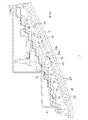
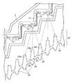
図1は、実施の形態に係る車両用灯具の横方向断面図である。本実施の形態では、車両用灯具として、テールランプを例に説明する。 FIG. 1 is a lateral cross-sectional view of a vehicular lamp according to an embodiment. In the present embodiment, a tail lamp will be described as an example of a vehicular lamp.
車両用灯具1は、ランプボディ2、カバー(アウターレンズ)4、複数の光源10、支持部材12、導光体20、インナーレンズ40、を備える。光源10、支持部材12、導光体20、インナーレンズ40は、ランプボディ2およびカバー4が形成する内部空間である灯室6に配置される。
The
複数の光源10は、所望の発光パターンに沿って、列状に離間して配置される。光源10の照射方向は、車両用灯具1の前方(車両後方)を向くように揃えられる。光源10はたとえばLED(発光ダイオード)や半導体レーザなどの半導体光源であり、フレキシブル基板14上に実装されている。フレキシブル基板14は、支持部材12に沿うようにして実装され、これにより複数の光源10は、支持部材12によって階段状に支持される。導光体20は、その裏面に複数の光源10からの光を受け、その表面から出射する。
The plurality of
インナーレンズ40は、複数の光源10と導光体20の間に挿入され、光源10からの光を屈折により拡散させ、導光体20の裏面に導入する。インナーレンズ40の複数の光源10と対向する表面42には、光源10の配列方向D1に連続するシリンドリカルステップ44が形成されることが望ましい。これにより複数の光源10からの光を横方向に好適に拡散し、導光体20に均一に導入できる。導光体20の表面から出射した光は、カバー4を介して車両後方に照射される。
The
続いて、導光体20の構成について説明する。導光体20は、ベース部分22、複数の裏面突起(裏面リブ)24、複数の表面突起(表面リブ)26を備える。ベース部分22は、その裏面22aが複数の光源10と対向して、複数の光源10の配列方向(図中矢印D1)に伸びる。
Then, the structure of the
複数の裏面突起24は、ベース部分22の裏面22aから、光源10の方向に向かって形成される。反対に複数の表面突起26は、ベース部分22の表面22bから車両用灯具1の光の照射方向(車両後方)に向かって形成される。
The plurality of
複数の裏面突起24および複数の表面突起26は、配列方向D1に離間して配置される。複数の裏面突起24および複数の表面突起26は、ベース部分22の複数の突起形成領域28に設けられる。突起形成領域28は、配列方向D1と垂直な幅方向(図中、矢印D2すなわち車両高さ方向)を長手とする断面形状を有する。
The plurality of
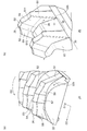
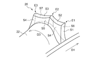
図2(a)、(b)は、導光体20を表面からみた斜視図である。図2(b)には、表面突起26を図2(a)と反対から見た図が示される。複数の表面突起26はそれぞれ、多面体形状を有する。多面体形状は、少なくとも、ベース部分22の表面22bに沿って、周方向(図中矢印D3)に連続する複数の面(周側面という)S1〜S5を含む。本実施の形態において表面突起26は、その底面(突起形成領域28)を除き、11面体(S1〜S11)で構成され、周側面S1〜S5に加えて、側面S6〜S8、S9〜S11を有する。
2A and 2B are perspective views of the
好ましくはベース部分22の表面22bのうち複数の突起形成領域28の間の領域30は、拡散処理(シボ加工)される。
Preferably, the
図3は、導光体20の表面突起26を図2(a)、(b)と異なる方向から見た斜視図である。複数の周側面S1〜S5のうち、車両後方からみたときに正面となる周側面S2〜S4は、ベース部分22の幅方向D2に関して凹形状を有している。周側面S2〜S4の曲率半径はたとえば10cm程度であってもよい。
FIG. 3 is a perspective view of the
ベース部分22は、図3にハッチングを付して示すように表面22bが凸、裏面22aが凹となる湾曲した断面形状(ハッチング部分)を有してもよい。表面突起26を凸湾曲面に形成することで、表面突起26により演出される立体感をさらに増幅することができる。
As shown in FIG. 3 with hatching, the
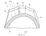
続いて裏面突起24について説明する。図4は、導光体20の一部を裏面からみた図である。図5は、導光体20と光源10の位置関係を示す図である。複数の裏面突起24は、光源10の配列方向D1に交互に配置される複数の第1突起24aと複数の第2突起24bを含む。第1突起24aはそれぞれ、複数の光源10の対応するひとつの光軸上またはその近傍に配置される。一方、第2突起24bはそれぞれ、隣接する2個の第1突起24aの間に配置される。複数の第1突起24aの先端は凸形状を有しており、複数の第2突起24bの先端は凹形状を有している。つまり第1突起24aと第2突起24bによって、光源10の配列方向D1に向かって凸ステップと凹ステップが交互に形成される。
Next, the
以上が車両用灯具1の構成である。続いてその動作を説明する。
図5に示すように、光源10からの出射した光は、インナーレンズ40により拡散され、導光体20の裏面突起24に入射する。インナーレンズ40を挿入したことにより、ひとつの裏面突起24には、さまざまな角度から光が入射することとなる。
The above is the configuration of the
As shown in FIG. 5, the light emitted from the
裏面突起24から入射した光は、ベース部分22の内部を多重反射しながら車両後方に向かって進み、その一部が表面突起26に導入され、残りはベース部分22の突起形成領域28以外の領域30に漏れる。表面突起26に導入された光は、その表面から車両後方に照射される。また領域30に漏れた光により、領域30はぼんやりと発光することとなる。
The light incident from the
この車両用灯具1によれば以下の効果を得ることができる。
車両用灯具1では、点灯時においては、裏面突起24に入射した光源10からの光が表面突起に導入され、その多面体によって多重反射することにより、宝石のような輝き、立体感のある面発光を実現できる。また非点灯時においては、太陽光などの外光が表面突起26の多面体より反射され、またその内部に入射して多重反射することにより、宝石のような輝きを実現できる。
According to the
In the
また車両用灯具1では、図3に示すように、複数の周側面S2、S3、S4を、幅方向D2に凹形状とした。これにより、太陽光などの外光が表面突起26に入射した際に、幅方向D2に対して広がるように屈折させることができ、幅方向D2に凸形状として集光する場合に比べて、宝石のような輝きを強調できる。
Moreover, in the
また車両用灯具1では、図5に示すように、裏面突起24を、第1突起24aと第2突起24bを交互に配置する構成とした。これにより、第1突起24aにより主として光軸を共有する1個の光源10からの光を集光でき、第2突起24bにより隣接する2個の光源10からの斜めに入射する光を集光でき、導光体20を均一に光らせることができる。言い換えれば、光源10と裏面突起24を同数として1対1で対応づけた場合に比べて、少ない個数の光源10で、規則的な均一発光を実現できる。また、光源1個に対して2個の表面突起26を配置することで、より宝石調の輝きを強めることができる。
Moreover, in the
また図3に現われるように、ベース部分22を、その表面22bが凸となる断面形状とした。湾曲面に表面突起26を形成することで、立体感を高めることができる。
As shown in FIG. 3, the
また複数の光源10と導光体20の間に、インナーレンズを挿入したことにより、光源10からの光を多方向に拡散し、実効的な指向性を弱めることができる。これにより、点光り感を減少でき、灯具全体を均一に発光させることができる。また表面突起26に対してさまざまな角度から光が入射することとなり、内部の多重反射により宝石調の輝きを際立たせることができる。
Moreover, by inserting an inner lens between the plurality of
上述した宝石調の輝きや立体感は、車両の安全性を高めるという車両用灯具1の本来の機能に加えて、車両自体の高級感の演出に資するものであり、大きな付加価値を生ずるものである。
In addition to the original function of the
また、ベース部分22の表面22bのうち複数の突起形成領域28の間の領域30を、シボ加工することとした。これにより、宝石調に発光する突起の部分(領域28)と、マットに発光する部分(領域30)が交互に現われることになり、それらのコントラストにより、一層、宝石調を強調することができ、また立体感を演出できる。
In addition, the
以上、本発明について、実施の形態をもとに説明した。この実施の形態は例示であり、それらの各構成要素の組み合わせにいろいろな変形例が可能なこと、またそうした変形例も本発明の範囲にあることは当業者に理解されるところである。以下、こうした変形例について説明する。 The present invention has been described based on the embodiments. This embodiment is an exemplification, and it is understood by those skilled in the art that various modifications can be made to combinations of the respective constituent elements, and such modifications are also within the scope of the present invention. Hereinafter, such modifications will be described.
(第1変形例)
実施の形態では、表面突起26を11面体で形成したが、本発明はそれには限定されない。たとえば側面にあたるS6〜S8は単一平面であってもよいし、同様に反対の側面にあたるS8〜S11は単一平面であってもよい。
(First modification)
In the embodiment, the
(第2変形例)
図6は、変形例に係る表面突起26の斜視図である。図6に示すように周方向D3に連続する周側面の個数は4個であってもよい。この場合、表面突起26は底面を除いて8面体であってもよい。あるいは、周方向D3に連続する面の個数は6個以上であってもよい。
(Second modification)
FIG. 6 is a perspective view of the
上述した宝石調の輝きは、図2に示す周側面S1〜S5(S1〜S4)の境界をなす辺(エッジ)E1〜E4、図6に示す周側面S1〜S4の境界をなす辺E1〜E3によって演出されるものと捉えることができる。この観点から言えば、周側面の境界をなす辺であって、車両後方から視認可能な辺の個数は、最低2個であり、3個以上であることが好ましい。 The jewel-like shine described above is the sides (edges) E1 to E4 forming the boundaries of the peripheral side surfaces S1 to S5 (S1 to S4) shown in FIG. 2, and the sides E1 to E1 forming the boundaries of the peripheral side surfaces S1 to S4 shown in FIG. It can be understood that it is produced by E3. From this viewpoint, the number of sides forming the boundary of the peripheral side surface and visible from the rear of the vehicle is at least two, and preferably three or more.
あるいは、図6に示す表面突起26と、図2の表面突起26を、組み合わせて用いてもよい。また異なる形状の表面突起26を組み合わせて設ける場合、複数の表面突起26の形状は、配列方向D1に関して連続的に徐変してもよい。これにより、車両用灯具1のあるい部位では繊細な、ある部位では荒々しいといった異なる宝石調を演出できる。
Alternatively, the
(第3変形例)
光源10の指向性がそれほど強くない場合には、インナーレンズ40は省略してもよい。
(Third Modification)
If the directivity of the
(第4変形例)
実施の形態では、車両用灯具1の1形態としてテールランプを説明したが、車両コーナーに配置されるリアコンビネーションランプに適用してもよい。
(Fourth modification)
In the embodiment, the tail lamp has been described as one form of the
実施の形態にもとづき、具体的な語句を用いて本発明を説明したが、実施の形態は、本発明の原理、応用を示しているにすぎず、実施の形態には、請求の範囲に規定された本発明の思想を逸脱しない範囲において、多くの変形例や配置の変更が認められる。 Although the present invention has been described using specific terms based on the embodiments, the embodiments only illustrate the principles and applications of the present invention, and the embodiments are defined in the claims. Many variations and modifications of the arrangement are permitted without departing from the spirit of the present invention.
1…車両用灯具、2…ランプボディ、4…カバー、10…光源、12…支持部材、14…フレキシブル基板、20…導光体、22…ベース部分、22a…裏面、22b…表面、24…裏面突起、24a…第1突起、24b…第2突起、26…表面突起、28…突起形成領域、40…インナーレンズ。
DESCRIPTION OF
Claims (10)
その裏面に前記複数の光源からの光を受け、その表面から出射する導光体と、
を備え、
前記導光体は、
その裏面が前記複数の光源と対向しており、前記第1方向に離間する複数の突起形成領域を有し、前記複数の突起形成領域はそれぞれ、第1方向を短手とし、前記第1方向と垂直な第2方向を長手としている、ベース部分と、
前記複数の突起形成領域から、前記ベース部分の表面側に突起している複数の表面突起と、
前記ベース部分の裏面側に、前記複数の表面突起とオーバーラップして設けられた複数の裏面突起と、
を備え、
前記複数の表面突起はそれぞれ、前記突起形成領域の一の短辺から別の短辺に至る周方向に連続する4個以上の面を含む多面体形状を有することを特徴とする車両用灯具。 A plurality of light sources arranged in a row in the first direction ;
A light guide that receives light from the plurality of light sources on the back surface and emits light from the surface;
With
The light guide is
The back surface has a plurality of projection formation regions facing the plurality of light sources and spaced apart in the first direction, and each of the plurality of projection formation regions has a short first direction, and the first direction A base portion having a second direction perpendicular to the longitudinal direction, and
A plurality of surface protrusions protruding from the plurality of protrusion forming regions to the surface side of the base portion ;
A plurality of back surface protrusions provided on the back surface side of the base portion so as to overlap the plurality of surface surface protrusions,
With
Wherein each of the plurality of surface protrusions, vehicle lamp characterized by having four or more faces of including polyhedral shape continuous in the circumferential direction leading to another short side from one short side of the projection forming region.
それぞれが前記複数の光源の対応するひとつの光軸上またはその近傍に配置される複数の第1突起と、
それぞれが隣接する2個の第1突起の間に配置される、複数の第2突起と、
を含み、
前記複数の第1突起それぞれの先端は凸形状に湾曲し、前記複数の第2突起それぞれの先端は凹形状に湾曲することを特徴とする請求項1または2に記載の車両用灯具。 The plurality of back surface protrusions are
A plurality of first protrusions each disposed on or near one optical axis corresponding to the plurality of light sources;
A plurality of second protrusions each disposed between two adjacent first protrusions;
Including
3. The vehicular lamp according to claim 1 , wherein tips of the plurality of first protrusions are curved in a convex shape, and tips of the plurality of second projections are curved in a concave shape. 4.
その裏面に前記複数の光源からの光を受け、その表面から出射する導光体と、 A light guide that receives light from the plurality of light sources on the back surface and emits light from the surface;
を備え、 With
前記導光体は、 The light guide is
その裏面が前記複数の光源と対向しており、前記第1方向に離間する複数の突起形成領域を有し、前記複数の突起形成領域はそれぞれ、第1方向を短手とし、前記第1方向と垂直な第2方向を長手としている、ベース部分と、 The back surface has a plurality of projection formation regions facing the plurality of light sources and spaced apart in the first direction, and each of the plurality of projection formation regions has a short first direction, and the first direction A base portion having a second direction perpendicular to the longitudinal direction, and
前記複数の突起形成領域から、前記ベース部分の表面側に突起している複数の表面突起と、 A plurality of surface protrusions protruding from the plurality of protrusion forming regions to the surface side of the base portion;
を備え、 With
前記複数の表面突起はそれぞれ、車両後方から視認可能であってかつ前記第1方向に伸びる辺を、3個以上有することを特徴とする車両用灯具。 Each of the plurality of surface protrusions has three or more sides that are visible from the rear of the vehicle and extend in the first direction.
Priority Applications (5)
| Application Number | Priority Date | Filing Date | Title |
|---|---|---|---|
| JP2014191862A JP6445818B2 (en) | 2014-09-19 | 2014-09-19 | Vehicle lighting |
| US14/849,759 US9890920B2 (en) | 2014-09-19 | 2015-09-10 | Vehicular lamp |
| FR1558708A FR3026161B1 (en) | 2014-09-19 | 2015-09-16 | VEHICLE LAMP |
| CN201510599668.7A CN105444082B (en) | 2014-09-19 | 2015-09-18 | Lamps apparatus for vehicle |
| DE102015218056.5A DE102015218056A1 (en) | 2014-09-19 | 2015-09-21 | vehicle light |
Applications Claiming Priority (1)
| Application Number | Priority Date | Filing Date | Title |
|---|---|---|---|
| JP2014191862A JP6445818B2 (en) | 2014-09-19 | 2014-09-19 | Vehicle lighting |
Publications (2)
| Publication Number | Publication Date |
|---|---|
| JP2016062844A JP2016062844A (en) | 2016-04-25 |
| JP6445818B2 true JP6445818B2 (en) | 2018-12-26 |
Family
ID=55445009
Family Applications (1)
| Application Number | Title | Priority Date | Filing Date |
|---|---|---|---|
| JP2014191862A Expired - Fee Related JP6445818B2 (en) | 2014-09-19 | 2014-09-19 | Vehicle lighting |
Country Status (5)
| Country | Link |
|---|---|
| US (1) | US9890920B2 (en) |
| JP (1) | JP6445818B2 (en) |
| CN (1) | CN105444082B (en) |
| DE (1) | DE102015218056A1 (en) |
| FR (1) | FR3026161B1 (en) |
Families Citing this family (9)
| Publication number | Priority date | Publication date | Assignee | Title |
|---|---|---|---|---|
| CN110382949B (en) * | 2017-03-07 | 2021-10-26 | 黑拉有限责任两合公司 | Lighting device for a vehicle |
| US10344936B2 (en) * | 2017-09-26 | 2019-07-09 | Nissan North America, Inc. | Vehicle light assembly |
| DE102018104124B4 (en) * | 2018-02-23 | 2025-05-28 | Automotive Lighting Reutlingen Gmbh | Lighting module for a motor vehicle |
| WO2020049931A1 (en) * | 2018-09-05 | 2020-03-12 | テイ・エス テック株式会社 | Vehicle illumination device and vehicle door |
| US10780819B2 (en) * | 2018-12-19 | 2020-09-22 | Ficosa North America Corporation | Vehicle winglet with sequential blinker |
| GB2585687B (en) * | 2019-07-11 | 2021-08-18 | Dyson Technology Ltd | Vehicle lamps |
| US10738962B1 (en) * | 2019-09-06 | 2020-08-11 | T.Y.C. Brother Industrial Co., Ltd. | Multi-segment vehicle turning light lamp |
| JP7344089B2 (en) * | 2019-11-01 | 2023-09-13 | スタンレー電気株式会社 | Vehicle lights |
| JP7536817B2 (en) * | 2022-03-17 | 2024-08-20 | 嘉利日本株式会社 | Optical lenses and lights for vehicles |
Family Cites Families (22)
| Publication number | Priority date | Publication date | Assignee | Title |
|---|---|---|---|---|
| US5938324A (en) * | 1996-10-07 | 1999-08-17 | Cisco Technology, Inc. | Light pipe |
| JP2000133011A (en) * | 1998-10-20 | 2000-05-12 | Ichikoh Ind Ltd | Automotive lighting |
| DE10037005A1 (en) | 2000-07-29 | 2002-02-07 | Hella Kg Hueck & Co | Light for vehicles |
| JP3984023B2 (en) | 2001-11-02 | 2007-09-26 | 株式会社小糸製作所 | Vehicle lamp |
| DE10231326A1 (en) | 2002-07-11 | 2004-02-19 | Hella Kg Hueck & Co. | Light unit for automobile e.g. automobile headlamp, has spaced light source elements associated with light conduction elements positioned behind light disc |
| JP4300927B2 (en) * | 2003-07-31 | 2009-07-22 | 市光工業株式会社 | Vehicle lighting |
| JP2005158362A (en) | 2003-11-21 | 2005-06-16 | Stanley Electric Co Ltd | Vehicle lighting |
| JP4290607B2 (en) * | 2004-06-04 | 2009-07-08 | 株式会社小糸製作所 | Vehicle lighting |
| US7670039B2 (en) * | 2006-03-17 | 2010-03-02 | Lutron Electronics Co., Inc. | Status indicator lens and light pipe structure for a dimmer switch |
| DE102007019688A1 (en) | 2007-04-24 | 2008-10-30 | Hella Kgaa Hueck & Co. | Signal light for motor vehicles, has housing, in which light source unit and multiple light conducting elements are assigned to light source unit and housing is covered by translucent sealing disk |
| DE102008037264A1 (en) | 2008-08-11 | 2010-02-18 | GM Global Technology Operations, Inc., Detroit | Lamp glass for motor vehicle lamp, particularly rear lamp, has external disk for covering lamp housing, where external disk has attachment distant from external disk |
| JP5374284B2 (en) * | 2009-09-09 | 2013-12-25 | スタンレー電気株式会社 | Lamp having a light guide |
| JP5553643B2 (en) | 2010-02-24 | 2014-07-16 | スタンレー電気株式会社 | Vehicle lighting |
| CN202048479U (en) * | 2010-11-08 | 2011-11-23 | 马瑞利汽车零部件(芜湖)有限公司 | LED effect imitating automobile taillight |
| JP2013026008A (en) * | 2011-07-20 | 2013-02-04 | Koito Mfg Co Ltd | Vehicular lamp |
| JP5810327B2 (en) * | 2011-08-25 | 2015-11-11 | パナソニックIpマネジメント株式会社 | lighting equipment |
| JP2013131386A (en) * | 2011-12-21 | 2013-07-04 | Stanley Electric Co Ltd | Lens for led light source and lens array |
| DE102012213845B4 (en) * | 2012-08-03 | 2015-05-28 | Automotive Lighting Reutlingen Gmbh | Light guide and light module |
| KR102024291B1 (en) * | 2012-12-18 | 2019-09-23 | 엘지이노텍 주식회사 | Lamp unit and vehicle lamp apparatus for using the same |
| JP2014149963A (en) * | 2013-01-31 | 2014-08-21 | Koito Mfg Co Ltd | Vehicle lighting fixture |
| DE202013001767U1 (en) | 2013-02-23 | 2013-03-14 | Automotive Lighting Reutlingen Gmbh | Motor vehicle lamp with a homogeneous bright luminous appearance image |
| JP6222805B2 (en) | 2013-03-26 | 2017-11-01 | 株式会社日立ハイテクサイエンス | Charged particle beam apparatus and observation image forming method |
-
2014
- 2014-09-19 JP JP2014191862A patent/JP6445818B2/en not_active Expired - Fee Related
-
2015
- 2015-09-10 US US14/849,759 patent/US9890920B2/en not_active Expired - Fee Related
- 2015-09-16 FR FR1558708A patent/FR3026161B1/en not_active Expired - Fee Related
- 2015-09-18 CN CN201510599668.7A patent/CN105444082B/en not_active Expired - Fee Related
- 2015-09-21 DE DE102015218056.5A patent/DE102015218056A1/en not_active Withdrawn
Also Published As
| Publication number | Publication date |
|---|---|
| US9890920B2 (en) | 2018-02-13 |
| CN105444082A (en) | 2016-03-30 |
| FR3026161A1 (en) | 2016-03-25 |
| FR3026161B1 (en) | 2020-02-21 |
| CN105444082B (en) | 2019-04-16 |
| US20160084467A1 (en) | 2016-03-24 |
| DE102015218056A1 (en) | 2016-03-24 |
| JP2016062844A (en) | 2016-04-25 |
Similar Documents
| Publication | Publication Date | Title |
|---|---|---|
| JP6445818B2 (en) | Vehicle lighting | |
| JP4290601B2 (en) | Vehicle lamp unit and vehicle lamp | |
| JP2004047351A (en) | Vehicle lighting | |
| JP4290607B2 (en) | Vehicle lighting | |
| JP2012190762A (en) | Lamp fitting for vehicle | |
| JP2011175817A (en) | Vehicular lighting fixture | |
| JP2012230862A (en) | Vehicle lamp | |
| JP2015076249A (en) | Vehicular lighting fixture | |
| JP2014041787A (en) | Vehicular lighting appliance | |
| JP6173329B2 (en) | Optical elements for light shaping | |
| JP2016085829A (en) | Vehicular lighting fixture | |
| CN104797880B (en) | Signals of vehicles device with 3-D effect | |
| CN105121952B (en) | Equipment for light output including LED light source and reflector | |
| JP5435257B2 (en) | Vehicle signal lights | |
| JP2005190954A (en) | Lighting device | |
| JP5575627B2 (en) | Light bulb type LED lamp | |
| JP2017022035A (en) | Light projection unit | |
| JP6281393B2 (en) | Vehicle lamp and lens body | |
| JP2015210317A (en) | Display device | |
| JP6032790B2 (en) | Vehicle lighting | |
| JP2006073289A (en) | Vehicle sign light | |
| JP2002025310A (en) | Vehicle lighting | |
| JP2017068903A (en) | LED module | |
| JP2005353374A (en) | Vehicle lighting | |
| CN203363986U (en) | Thin LED Lens |
Legal Events
| Date | Code | Title | Description |
|---|---|---|---|
| A621 | Written request for application examination |
Free format text: JAPANESE INTERMEDIATE CODE: A621 Effective date: 20170802 |
|
| A977 | Report on retrieval |
Free format text: JAPANESE INTERMEDIATE CODE: A971007 Effective date: 20180419 |
|
| A131 | Notification of reasons for refusal |
Free format text: JAPANESE INTERMEDIATE CODE: A131 Effective date: 20180424 |
|
| A521 | Request for written amendment filed |
Free format text: JAPANESE INTERMEDIATE CODE: A523 Effective date: 20180618 |
|
| TRDD | Decision of grant or rejection written | ||
| A01 | Written decision to grant a patent or to grant a registration (utility model) |
Free format text: JAPANESE INTERMEDIATE CODE: A01 Effective date: 20181127 |
|
| A61 | First payment of annual fees (during grant procedure) |
Free format text: JAPANESE INTERMEDIATE CODE: A61 Effective date: 20181130 |
|
| R150 | Certificate of patent or registration of utility model |
Ref document number: 6445818 Country of ref document: JP Free format text: JAPANESE INTERMEDIATE CODE: R150 |
|
| LAPS | Cancellation because of no payment of annual fees |