JP6442339B2 - Heat treatment apparatus and heat treatment method - Google Patents
Heat treatment apparatus and heat treatment method Download PDFInfo
- Publication number
- JP6442339B2 JP6442339B2 JP2015063949A JP2015063949A JP6442339B2 JP 6442339 B2 JP6442339 B2 JP 6442339B2 JP 2015063949 A JP2015063949 A JP 2015063949A JP 2015063949 A JP2015063949 A JP 2015063949A JP 6442339 B2 JP6442339 B2 JP 6442339B2
- Authority
- JP
- Japan
- Prior art keywords
- control
- temperature
- value
- heat treatment
- unit
- Prior art date
- Legal status (The legal status is an assumption and is not a legal conclusion. Google has not performed a legal analysis and makes no representation as to the accuracy of the status listed.)
- Active
Links
Images


Classifications
-
- H—ELECTRICITY
- H01—ELECTRIC ELEMENTS
- H01L—SEMICONDUCTOR DEVICES NOT COVERED BY CLASS H10
- H01L21/00—Processes or apparatus adapted for the manufacture or treatment of semiconductor or solid state devices or of parts thereof
- H01L21/67—Apparatus specially adapted for handling semiconductor or electric solid state devices during manufacture or treatment thereof; Apparatus specially adapted for handling wafers during manufacture or treatment of semiconductor or electric solid state devices or components ; Apparatus not specifically provided for elsewhere
- H01L21/67005—Apparatus not specifically provided for elsewhere
- H01L21/67011—Apparatus for manufacture or treatment
- H01L21/67098—Apparatus for thermal treatment
-
- H—ELECTRICITY
- H01—ELECTRIC ELEMENTS
- H01L—SEMICONDUCTOR DEVICES NOT COVERED BY CLASS H10
- H01L21/00—Processes or apparatus adapted for the manufacture or treatment of semiconductor or solid state devices or of parts thereof
- H01L21/67—Apparatus specially adapted for handling semiconductor or electric solid state devices during manufacture or treatment thereof; Apparatus specially adapted for handling wafers during manufacture or treatment of semiconductor or electric solid state devices or components ; Apparatus not specifically provided for elsewhere
- H01L21/67005—Apparatus not specifically provided for elsewhere
- H01L21/67242—Apparatus for monitoring, sorting or marking
- H01L21/67248—Temperature monitoring
-
- F—MECHANICAL ENGINEERING; LIGHTING; HEATING; WEAPONS; BLASTING
- F25—REFRIGERATION OR COOLING; COMBINED HEATING AND REFRIGERATION SYSTEMS; HEAT PUMP SYSTEMS; MANUFACTURE OR STORAGE OF ICE; LIQUEFACTION SOLIDIFICATION OF GASES
- F25B—REFRIGERATION MACHINES, PLANTS OR SYSTEMS; COMBINED HEATING AND REFRIGERATION SYSTEMS; HEAT PUMP SYSTEMS
- F25B21/00—Machines, plants or systems, using electric or magnetic effects
- F25B21/02—Machines, plants or systems, using electric or magnetic effects using Peltier effect; using Nernst-Ettinghausen effect
- F25B21/04—Machines, plants or systems, using electric or magnetic effects using Peltier effect; using Nernst-Ettinghausen effect reversible
-
- H—ELECTRICITY
- H01—ELECTRIC ELEMENTS
- H01L—SEMICONDUCTOR DEVICES NOT COVERED BY CLASS H10
- H01L21/00—Processes or apparatus adapted for the manufacture or treatment of semiconductor or solid state devices or of parts thereof
- H01L21/02—Manufacture or treatment of semiconductor devices or of parts thereof
- H01L21/027—Making masks on semiconductor bodies for further photolithographic processing not provided for in group H01L21/18 or H01L21/34
-
- H—ELECTRICITY
- H01—ELECTRIC ELEMENTS
- H01L—SEMICONDUCTOR DEVICES NOT COVERED BY CLASS H10
- H01L21/00—Processes or apparatus adapted for the manufacture or treatment of semiconductor or solid state devices or of parts thereof
- H01L21/02—Manufacture or treatment of semiconductor devices or of parts thereof
- H01L21/04—Manufacture or treatment of semiconductor devices or of parts thereof the devices having at least one potential-jump barrier or surface barrier, e.g. PN junction, depletion layer or carrier concentration layer
- H01L21/18—Manufacture or treatment of semiconductor devices or of parts thereof the devices having at least one potential-jump barrier or surface barrier, e.g. PN junction, depletion layer or carrier concentration layer the devices having semiconductor bodies comprising elements of Group IV of the Periodic System or AIIIBV compounds with or without impurities, e.g. doping materials
- H01L21/30—Treatment of semiconductor bodies using processes or apparatus not provided for in groups H01L21/20 - H01L21/26
- H01L21/324—Thermal treatment for modifying the properties of semiconductor bodies, e.g. annealing, sintering
-
- H—ELECTRICITY
- H01—ELECTRIC ELEMENTS
- H01L—SEMICONDUCTOR DEVICES NOT COVERED BY CLASS H10
- H01L21/00—Processes or apparatus adapted for the manufacture or treatment of semiconductor or solid state devices or of parts thereof
- H01L21/67—Apparatus specially adapted for handling semiconductor or electric solid state devices during manufacture or treatment thereof; Apparatus specially adapted for handling wafers during manufacture or treatment of semiconductor or electric solid state devices or components ; Apparatus not specifically provided for elsewhere
- H01L21/67005—Apparatus not specifically provided for elsewhere
- H01L21/67011—Apparatus for manufacture or treatment
- H01L21/67098—Apparatus for thermal treatment
- H01L21/67103—Apparatus for thermal treatment mainly by conduction
-
- H—ELECTRICITY
- H01—ELECTRIC ELEMENTS
- H01L—SEMICONDUCTOR DEVICES NOT COVERED BY CLASS H10
- H01L21/00—Processes or apparatus adapted for the manufacture or treatment of semiconductor or solid state devices or of parts thereof
- H01L21/67—Apparatus specially adapted for handling semiconductor or electric solid state devices during manufacture or treatment thereof; Apparatus specially adapted for handling wafers during manufacture or treatment of semiconductor or electric solid state devices or components ; Apparatus not specifically provided for elsewhere
- H01L21/67005—Apparatus not specifically provided for elsewhere
- H01L21/67242—Apparatus for monitoring, sorting or marking
- H01L21/67253—Process monitoring, e.g. flow or thickness monitoring
-
- H—ELECTRICITY
- H01—ELECTRIC ELEMENTS
- H01L—SEMICONDUCTOR DEVICES NOT COVERED BY CLASS H10
- H01L22/00—Testing or measuring during manufacture or treatment; Reliability measurements, i.e. testing of parts without further processing to modify the parts as such; Structural arrangements therefor
- H01L22/20—Sequence of activities consisting of a plurality of measurements, corrections, marking or sorting steps
-
- F—MECHANICAL ENGINEERING; LIGHTING; HEATING; WEAPONS; BLASTING
- F25—REFRIGERATION OR COOLING; COMBINED HEATING AND REFRIGERATION SYSTEMS; HEAT PUMP SYSTEMS; MANUFACTURE OR STORAGE OF ICE; LIQUEFACTION SOLIDIFICATION OF GASES
- F25B—REFRIGERATION MACHINES, PLANTS OR SYSTEMS; COMBINED HEATING AND REFRIGERATION SYSTEMS; HEAT PUMP SYSTEMS
- F25B2321/00—Details of machines, plants or systems, using electric or magnetic effects
- F25B2321/02—Details of machines, plants or systems, using electric or magnetic effects using Peltier effects; using Nernst-Ettinghausen effects
- F25B2321/021—Control thereof
- F25B2321/0212—Control thereof of electric power, current or voltage
Description
本発明は、基板を熱処理する熱処理装置および熱処理方法に関する。 The present invention relates to a heat treatment apparatus and a heat treatment method for heat treating a substrate.
半導体基板、液晶表示装置用基板、プラズマディスプレイ用基板、光ディスク用基板、磁気ディスク用基板、光磁気ディスク用基板またはフォトマスク用基板等の各種基板に熱処理を行うために、熱処理装置が用いられている。 In order to perform heat treatment on various substrates such as a semiconductor substrate, a liquid crystal display substrate, a plasma display substrate, an optical disk substrate, a magnetic disk substrate, a magneto-optical disk substrate, or a photomask substrate, a heat treatment apparatus is used. Yes.
特許文献1に記載された基板冷却装置は、温度設定器および冷却プレートを有する。冷却プレートは、伝熱プレートおよびペルチェ素子を含む。伝熱プレートには、冷却処理前の高温の基板が搬入される。温度設定器には、基板冷却目標温度および伝熱プレートの初期温度が設定される。伝熱プレートの初期温度は、基板冷却目標温度以下である。
The substrate cooling apparatus described in
基板が伝熱プレートに搬入されるまでは、伝熱プレートは設定された初期温度に制御される。高温の基板が伝熱プレートに搬入された場合、ペルチェ素子による最大能力で伝熱プレートおよび基板の冷却が行われる。ペルチェ素子による最大能力での冷却とは、基板用の温度センサおよび伝熱プレート用の温度センサの出力に応じて冷却する程度を増減調節せずにペルチェ素子をその最大能力で駆動して冷却することをいう。 Until the substrate is carried into the heat transfer plate, the heat transfer plate is controlled to the set initial temperature. When a high-temperature substrate is carried into the heat transfer plate, the heat transfer plate and the substrate are cooled with the maximum capacity of the Peltier element. Cooling at the maximum capacity by the Peltier element means that the Peltier element is driven at its maximum capacity for cooling without adjusting the degree of cooling according to the output of the temperature sensor for the substrate and the temperature sensor for the heat transfer plate. That means.
基板の温度が設定された基板冷却目標温度に達すると、基板が伝熱プレートによる熱の影響を受けない位置まで冷却プレートから離間される。これにより、当該基板に対する冷却処理が終了する。その後、次の基板の冷却処理に備えて、伝熱プレートの温度が設定された初期温度に戻される。 When the temperature of the substrate reaches the set substrate cooling target temperature, the substrate is separated from the cooling plate to a position where it is not affected by heat from the heat transfer plate. Thereby, the cooling process for the substrate is completed. Thereafter, the temperature of the heat transfer plate is returned to the set initial temperature in preparation for the next substrate cooling process.
特許文献1の基板冷却装置によれば、高温の基板を基板冷却目標温度まで高速で冷却することができる。しかしながら、冷却処理の後、ペルチェ素子により最大能力で冷却された伝熱プレートの温度を初期温度に戻す制御を逐一行う必要がある。そのため、制御が複雑化するとともに、基板冷却装置の処理効率が低下する。
According to the substrate cooling apparatus of
本発明の目的は、簡単な制御により基板の熱処理を正確にかつ高効率で行うことが可能な熱処理装置および熱処理方法を提供することである。 An object of the present invention is to provide a heat treatment apparatus and a heat treatment method capable of performing heat treatment of a substrate accurately and with high efficiency by simple control.
(1)第1の発明に係る熱処理装置は、基板に熱処理を行う熱処理装置であって、基板が載置されるプレートと、プレートを冷却または加熱するように配置される熱処理部と、熱処理部の温度を調整する温度調整部と、プレートの温度を検出する温度検出部と、温度検出部により検出された温度に基づいて、プレートの温度を設定された値に維持するために温度調整部に与えられるべき制御値を制御演算値として算出する制御値算出部と、制御値算出部により算出された制御演算値を温度調整部に与える第1の制御と、制御値算出部により算出された制御演算値よりも高い制御設定値を温度調整部に与える第2の制御とを行う制御切替部とを備え、制御切替部は、制御値算出部により算出された制御演算値が第1のしきい値以上に上昇した場合には、第1の制御を第2の制御に切り替え、制御値算出部により算出された制御演算値が第2のしきい値未満に低下した場合には、第2の制御を第1の制御に切り替える。 (1) A heat treatment apparatus according to a first aspect of the present invention is a heat treatment apparatus for performing a heat treatment on a substrate, a plate on which the substrate is placed, a heat treatment unit arranged to cool or heat the plate, and a heat treatment unit A temperature adjusting unit for adjusting the temperature of the plate, a temperature detecting unit for detecting the temperature of the plate, and a temperature adjusting unit for maintaining the plate temperature at a set value based on the temperature detected by the temperature detecting unit. A control value calculation unit that calculates a control value to be given as a control calculation value, a first control that gives a control calculation value calculated by the control value calculation unit to the temperature adjustment unit, and a control calculated by the control value calculation unit A control switching unit that performs a second control that provides the temperature adjustment unit with a control set value that is higher than the calculated value. The control switching unit has a control calculated value calculated by the control value calculating unit as a first threshold value. When it rises above the value The first control is switched to the second control, and when the control calculation value calculated by the control value calculation unit falls below the second threshold value, the second control is changed to the first control. Switch to.
この熱処理装置においては、基板が載置されるプレートが熱処理部により冷却または加熱される。熱処理部の温度が温度調整部により調整される。プレートの温度が検出される。検出された温度に基づいて、プレートの温度を設定された値に維持するために温度調整部に与えられるべき制御値が制御演算値として算出される。 In this heat treatment apparatus, the plate on which the substrate is placed is cooled or heated by the heat treatment unit. The temperature of the heat treatment part is adjusted by the temperature adjustment part. The temperature of the plate is detected. Based on the detected temperature, a control value to be given to the temperature adjustment unit in order to maintain the temperature of the plate at a set value is calculated as a control calculation value.
制御演算値が第2のしきい値未満である場合には、プレートの温度を設定された値に維持するために算出された制御演算値が温度調整部に与えられる(第1の制御)。これにより、プレートの温度が設定された値に維持される。一方、制御演算値が第1のしきい値以上に上昇した場合には、制御演算値よりも高い制御設定値が温度調整部に与えられる(第2の制御)。これにより、プレートの温度が短時間で設定された値に戻される。制御演算値が第2のしきい値未満まで低下すると、第1の制御が行われる。第1の制御においては、プレートの温度変化は緩やかであるため、大きなオーバーシュートおよびアンダーシュートは発生しない。 When the control calculation value is less than the second threshold value, the control calculation value calculated to maintain the plate temperature at the set value is given to the temperature adjustment unit (first control). Thereby, the temperature of the plate is maintained at the set value. On the other hand, when the control calculation value rises above the first threshold value, a control set value higher than the control calculation value is given to the temperature adjustment unit (second control). As a result, the temperature of the plate is returned to the set value in a short time. When the control calculation value falls below the second threshold value, the first control is performed. In the first control, since the temperature change of the plate is gentle, large overshoot and undershoot do not occur.
この構成によれば、第1の制御および第2の制御の切り替えにより、制御の即応性および安定性を向上させることができる。その結果、簡単な制御により基板の熱処理を正確にかつ高効率で行うことができる。 According to this configuration, the responsiveness and stability of the control can be improved by switching between the first control and the second control. As a result, the heat treatment of the substrate can be performed accurately and efficiently with simple control.
(2)制御設定値は、予め定められた第1および第2のしきい値よりも高くかつ温度調整部に対する最大の制御値以下であってもよい。 (2) The control set value may be higher than predetermined first and second threshold values and not more than the maximum control value for the temperature adjustment unit.
この構成によれば、制御演算値が第1のしきい値以上に上昇した場合には、高い制御設定値が温度調整部に与えられる。これにより、プレートの温度をより短時間で設定された値に戻すことができる。その結果、制御の安定性を維持しつつ即応性をより向上させることができる。 According to this configuration, when the control calculation value rises above the first threshold value, a high control set value is given to the temperature adjustment unit. Thereby, the temperature of the plate can be returned to the set value in a shorter time. As a result, the responsiveness can be further improved while maintaining the stability of the control.
(3)第1のしきい値と第2のしきい値とは互いに等しくてもよい。 (3) The first threshold value and the second threshold value may be equal to each other.
この場合、第1の制御を第2の制御に切り替えるときの制御演算値と第2の制御を第1の制御に切り替えるときの制御演算値とが等しいので、温度調整部の制御をより単純にすることができる。 In this case, since the control calculation value when the first control is switched to the second control is equal to the control calculation value when the second control is switched to the first control, the control of the temperature adjustment unit is simplified. can do.
(4)制御値は、プレートの温度を設定された値に維持するために熱処理部に供給されるべき電力と温度調整部が出力可能な最大電力との比率であってもよい。 (4) The control value may be a ratio between the power to be supplied to the heat treatment unit and the maximum power that can be output by the temperature adjustment unit in order to maintain the temperature of the plate at a set value.
この場合、第1および第2のしきい値を相対値として設定することができる。そのため、第1および第2のしきい値を容易に設定することができる。 In this case, the first and second threshold values can be set as relative values. Therefore, the first and second threshold values can be set easily.
(5)熱処理部はペルチェ素子を含んでもよい。この場合、温度調整部は熱処理部への電力を調整することにより、熱処理部の温度を高い応答性でかつ容易に調整することができる。 (5) The heat treatment part may include a Peltier element. In this case, the temperature adjustment unit can easily adjust the temperature of the heat treatment unit with high responsiveness by adjusting the power to the heat treatment unit.
(6)第2の発明に係る熱処理方法は、基板に熱処理を行う熱処理方法であって、基板が載置されるプレートを熱処理部により冷却または加熱するステップと、熱処理部の温度を温度調整部により調整するステップと、プレートの温度を検出するステップと、検出された温度に基づいて、プレートの温度を設定された値に維持するために温度調整部に与えられるべき制御値を制御演算値として算出するステップと、算出された制御演算値を温度調整部に与える第1の制御と、算出された制御演算値よりも高い制御設定値を温度調整部に与える第2の制御とを行うステップとを含み、第1の制御と第2の制御とを行うステップは、算出された制御演算値が第1のしきい値以上に上昇した場合には、第1の制御を第2の制御に切り替え、算出された制御演算値が第2のしきい値未満に低下した場合には、第2の制御を第1の制御に切り替えることを含む。 (6) A heat treatment method according to a second aspect of the present invention is a heat treatment method for performing heat treatment on a substrate, the step of cooling or heating a plate on which the substrate is placed by a heat treatment unit, and the temperature of the heat treatment unit being a temperature adjustment unit A step of detecting the temperature of the plate, a step of detecting the temperature of the plate, and a control value to be given to the temperature adjustment unit to maintain the temperature of the plate at a set value based on the detected temperature as a control calculation value A step of calculating, a first control for giving the calculated control calculation value to the temperature adjustment unit, and a second control for giving a control set value higher than the calculated control calculation value to the temperature adjustment unit; The step of performing the first control and the second control includes switching the first control to the second control when the calculated control calculation value rises above the first threshold value. Calculated When the control operation value drops below the second threshold comprises switching the second control to the first control.
この熱処理方法によれば、基板が載置されるプレートが熱処理部により冷却または加熱される。熱処理部の温度が温度調整部により調整される。プレートの温度が検出される。検出された温度に基づいて、プレートの温度を設定された値に維持するために温度調整部に与えられるべき制御値が制御演算値として算出される。 According to this heat treatment method, the plate on which the substrate is placed is cooled or heated by the heat treatment unit. The temperature of the heat treatment part is adjusted by the temperature adjustment part. The temperature of the plate is detected. Based on the detected temperature, a control value to be given to the temperature adjustment unit in order to maintain the temperature of the plate at a set value is calculated as a control calculation value.
制御演算値が第2のしきい値未満である場合には、プレートの温度を設定された値に維持するために算出された制御演算値が温度調整部に与えられる(第1の制御)。これにより、プレートの温度が設定された値に維持される。一方、制御演算値が第1のしきい値以上に上昇した場合には、制御演算値よりも高い制御設定値が温度調整部に与えられる(第2の制御)。これにより、プレートの温度が短時間で設定された値に戻される。制御演算値が第2のしきい値未満まで低下すると、第1の制御が行われる。第1の制御においては、プレートの温度変化は緩やかであるため、大きなオーバーシュートおよびアンダーシュートは発生しない。 When the control calculation value is less than the second threshold value, the control calculation value calculated to maintain the plate temperature at the set value is given to the temperature adjustment unit (first control). Thereby, the temperature of the plate is maintained at the set value. On the other hand, when the control calculation value rises above the first threshold value, a control set value higher than the control calculation value is given to the temperature adjustment unit (second control). As a result, the temperature of the plate is returned to the set value in a short time. When the control calculation value falls below the second threshold value, the first control is performed. In the first control, since the temperature change of the plate is gentle, large overshoot and undershoot do not occur.
この方法によれば、第1の制御および第2の制御の切り替えにより、制御の即応性および安定性を向上させることができる。その結果、簡単な制御により基板の熱処理を正確にかつ高効率で行うことができる。 According to this method, it is possible to improve control responsiveness and stability by switching between the first control and the second control. As a result, the heat treatment of the substrate can be performed accurately and efficiently with simple control.
本発明によれば、簡単な制御により基板の熱処理を正確にかつ高効率で行うことができる。 According to the present invention, heat treatment of a substrate can be performed accurately and efficiently with simple control.
(1)熱処理装置の構成
以下、本発明の実施の形態に係る熱処理装置および熱処理方法について図面を用いて説明する。なお、以下の説明において、基板とは、半導体基板、液晶表示装置用基板、プラズマディスプレイ用基板、光ディスク用基板、磁気ディスク用基板、光磁気ディスク用基板またはフォトマスク用基板等をいう。
(1) Configuration of Heat Treatment Apparatus Hereinafter, a heat treatment apparatus and a heat treatment method according to an embodiment of the present invention will be described with reference to the drawings. In the following description, the substrate means a semiconductor substrate, a liquid crystal display substrate, a plasma display substrate, an optical disk substrate, a magnetic disk substrate, a magneto-optical disk substrate, a photomask substrate, or the like.
図1は、本発明の一実施の形態に係る熱処理装置の構成を示す模式的側面図である。図2は、図1の熱処理装置100の模式的平面図である。図1に示すように、熱処理装置100は、制御装置10、プレート部20、温度調整部30、昇降装置40および温度検出部50を含む。
FIG. 1 is a schematic side view showing a configuration of a heat treatment apparatus according to an embodiment of the present invention. FIG. 2 is a schematic plan view of the
制御装置10は、記憶部11、昇降制御部12、温度算出部13、演算処理部14および出力制御部15を含む。昇降制御部12、温度算出部13、演算処理部14および出力制御部15は、CPU(Central Processing Unit;中央演算処理装置)により実現される。
The
プレート部20は、上部プレート21、下部プレート22および熱処理部23を含む。上部プレート21は、例えば円板形状を有する伝熱プレートである。上部プレート21には、熱処理が行われる基板Wが載置される。上部プレート21には、厚み方向に貫通する複数(本例では3個)の開口部21hが形成される。
The
下部プレート22は、例えば円板形状を有する放熱プレートである。下部プレート22には、厚み方向に貫通しかつ上部プレート21の複数の開口部21hにそれぞれ対応する複数の開口部22hが形成される。下部プレート22は、その中心が上部プレート21の中心と略一致する状態で上部プレート21の下方に配置される。この場合、上部プレート21の複数の開口部21hと下部プレート22の複数の開口部22hとはそれぞれ上下方向に重なる。
The
本実施の形態においては、熱処理部23は複数(図2の例では9個)の温調素子23aを含む。熱処理部23は、上部プレート21と下部プレート22との間に配置される。この状態で、上部プレート21と下部プレート22とが図示しないネジ等の固定部材により固定される。これにより、熱処理部23は上部プレート21および下部プレート22により狭持される。
In the present embodiment, the
本例においては、各温調素子23aは、冷却面および加熱面を有するペルチェ素子である。各温調素子23aは、冷却面が上部プレート21に接触しかつ加熱面が下部プレート22に接触するように配置される。この場合、プレート部20は、上部プレート21により基板Wを冷却処理するクーリングプレートとして機能する。各温調素子23aの加熱面から発生する熱は、基板Wの冷却処理に影響しないように下部プレート22により放出される。
In this example, each
各温調素子23aは温度調整部30に接続される。図1および図2においては、1つの温調素子23aと温度調整部30との接続のみが図示され、他の複数の温調素子23aと温度調整部30との接続の図示は省略されている。温度調整部30は、例えば電力供給部であり、制御装置10の出力制御部15による制御に基づいて温調素子23aに電力を出力として供給する。それにより、上部プレート21の温度が低下し、上部プレート21に載置された基板Wが所定の温度に冷却される。
Each
図1に示すように、昇降装置40は、複数の開口部21h,22hにそれぞれ対応する複数の昇降ピン41およびピン駆動部42を含む。複数の昇降ピン41は、下部プレート22の下方から複数の開口部22hおよび上部プレート21の複数の開口部21hにそれぞれ挿入される。
As shown in FIG. 1, the lifting
ピン駆動部42は、例えばアクチュエータであり、本例ではエアシリンダである。ピン駆動部42は、制御装置10の昇降制御部12による制御に基づいて、複数の昇降ピン41を上昇位置と下降位置との間で移動させる。ここで、上昇位置は、複数の昇降ピン41の先端が複数の開口部21h,22hを通して上部プレート21の上面よりも上方に突出する位置である。下降位置は、複数の昇降ピン41の先端が上部プレート21の上面よりも下方にある位置である。
The pin drive
温度検出部50は、測定対象の温度に応じて変化する特性値を有する温度検出素子である。温度検出素子は、熱電対であってもよいし、測温抵抗体であってもよいし、他の素子であってもよい。温度検出部50は、上部プレート21の略中央部に埋設される。なお、温度検出部50が熱電対である場合には、特性値は電位差(熱起電力)であり、温度検出部50が測温抵抗体である場合には、特性値は電気抵抗である。温度検出部50は、上部プレート21の温度に応じた特性値に基づいて検出値を制御装置10の温度算出部13に与える。
The
制御装置10の記憶部11には、上部プレート21の設定温度および後述する温度制御に関する種々の情報が記憶される。また、記憶部11には、昇降ピン41の昇降のタイミングを示す情報が記憶される。
The
昇降制御部12は、記憶部11に記憶されたタイミングを示す情報に基づいて、プレート部20への基板Wの搬入時またはプレート部20からの基板Wの搬出時に複数の昇降ピン41が上昇位置に移動するようにピン駆動部42を制御する。この場合、複数の昇降ピン41により基板Wが上部プレート21の上方に移動される。この状態で、複数の昇降ピン41と図示しない基板搬送装置との間で基板Wの受け渡しが行われる。
Based on the information indicating the timing stored in the
また、昇降制御部12は、記憶部11に記憶されたタイミングを示す情報に基づいて、基板Wの熱処理時に複数の昇降ピン41が下降位置に移動するようにピン駆動部42を制御する。これにより、基板Wが上部プレート21に載置される。
Further, the lifting
温度算出部13は、温度検出部50から与えられる検出値に基づいて、上部プレート21の温度を算出する。演算処理部14は、温度算出部13により算出された温度に基づいて、上部プレート21を設定温度に維持するために温度調整部30が熱処理部23に供給すべき出力(電力)を算出する。本例においては、設定温度は23℃である。出力制御部15は、記憶部11に記憶された出力制御に関する情報および演算処理部14により算出された結果に基づいて、温度調整部30が熱処理部23に供給する出力を制御する。
The
(2)上部プレートの温度制御
本例においては、まず、上部プレート21の温度が設定温度(本例では23℃)に制御される。次に、図示しない加熱処理装置により高温に加熱された基板Wが上部プレート21に載置される。そのため、上部プレート21の温度が設定温度から急激に上昇する。このような場合でも、上部プレート21の温度が設定温度に戻るように温度調整部30の制御が行われる。この制御においては、温度調整部30から熱処理部23への出力率が調整される。ここで、出力率は、上部プレート21を設定温度に維持するために熱処理部23に供給すべき出力と温度調整部30の供給可能な最大出力との比である。
(2) Temperature control of the upper plate In this example, first, the temperature of the
上記の制御において、即応性および安定性が向上されること、すなわち可能な限り短時間でかつ行き過ぎ量(オーバーシュートおよびアンダーシュート)が小さくなるように上部プレート21の温度が設定温度に戻されることが望まれる。通常、このような制御を行う場合には、フィードバック制御が用いられる。
In the above control, quick response and stability are improved, that is, the temperature of the
図3および図4は、比較例1,2における上部プレート21の温度制御をそれぞれ示すグラフである。図3および図4の横軸は経過時間を示し、縦軸は上部プレート21の温度および温度調整部30の出力率を示す。また、図3および図4においては、上部プレート21の温度変化を実線で示し、温度調整部30の出力率を点線で示す。比較例1,2においては、フィードバック制御としてPID(比例微分積分)制御が行われる。比較例2におけるPID制御のゲインは、比較例1におけるPID制御のゲインよりも大きい。
3 and 4 are graphs showing temperature control of the
比較例1においては、図3に示すように、初期時点で基板Wが上部プレート21に載置される。それにより、実線で示すように、上部プレート21の温度が設定温度から上昇する。この場合、点線で示すように、上部プレート21の温度変化を抑制するために出力率が上昇する。これにより、実線で示すように、上部プレート21の温度は低下し、設定温度近傍で収束する。また、点線で示すように、出力率は、上部プレート21の温度変化に応じて低下し、一定値に収束する。
In Comparative Example 1, as shown in FIG. 3, the substrate W is placed on the
比較例2においては、図4に示すように、初期時点で基板Wが上部プレート21に載置される。それにより、実線で示すように、上部プレート21の温度が設定温度から上昇する。この場合、点線で示すように、上部プレート21の温度変化を抑制するために出力率が上昇する。本例では、出力率は一時的に100%に達する。これにより、実線で示すように、上部プレート21の温度は比較的短い時間で低下し、オーバーシュートおよびアンダーシュートによる振動を繰り返しながら設定温度近傍で収束する。また、点線で示すように、出力率は、上部プレート21の温度変化に応じて低下し、振動を繰り返しながら一定値に収束する。
In Comparative Example 2, as shown in FIG. 4, the substrate W is placed on the
比較例1では、上部プレート21の温度のオーバーシュートはほとんど発生しない反面、基板Wが上部プレート21に載置されてから上部プレート21の温度が設定温度に戻るまでに比較的長い時間(本例では13.4秒)を要する。一方、比較例2では、基板Wが上部プレート21に載置されてから比較的短い時間(本例では11.5秒)で上部プレート21の温度が設定温度に戻る反面、上部プレート21の温度の大きなオーバーシュートおよびアンダーシュートが発生する。
In the comparative example 1, the temperature overshoot of the
このように、比較例1,2の比較から、通常のフィードバック制御では即応性と安定性とはトレードオフの関係にあり、ゲインの調整のみでは即応性および安定性の向上を両立させることは困難である。そこで、本実施の形態においては、制御装置10は即応性および安定性の向上を両立させるために以下の制御を行う。
Thus, from the comparison between Comparative Examples 1 and 2, there is a trade-off relationship between responsiveness and stability in normal feedback control, and it is difficult to achieve both improved responsiveness and stability only by adjusting the gain. It is. Therefore, in the present embodiment, the
図5は、本発明の実施の形態における上部プレート21の温度制御処理を示すフローチャートである。実施例においては、予め設定された温度調整部30の出力率のしきい値が記憶部11に記憶されている。しきい値は、上部プレート21の設定温度、基板Wのサイズおよび温度調整部30の最大出力等に基づいて決定される。本例では、しきい値は70%である。以下、図1、図2および図5を参照しながら制御装置10による温度制御処理を説明する。
FIG. 5 is a flowchart showing the temperature control process of the
まず、温度算出部13は、上部プレート21の温度を算出する(ステップS1)。次に、演算処理部14は、フィードバック制御を用いて上部プレート21の温度を設定値に維持するための出力率を算出する(ステップS2)。続いて、出力制御部15は、算出された出力率がしきい値未満であるか否かを判定する(ステップS3)。
First, the
ステップS3において、算出された出力率がしきい値未満である場合には、出力制御部15は、算出された出力率で熱処理部23に出力を供給する(ステップS4)。この場合、上部プレート21の温度を設定値に維持するフィードバック制御が行われる。その後、制御装置10はステップS1の処理に戻る。
In step S3, when the calculated output rate is less than the threshold value, the
一方、ステップS3において、算出された出力率がしきい値以上である場合には、出力制御部15は、100%の出力率で熱処理部23に出力を供給する(ステップS5)。この場合、熱処理部23に温度調整部30の最大出力を供給するフィードフォワード制御が行われる。その後、制御装置10はステップS1の処理に戻る。
On the other hand, if the calculated output rate is greater than or equal to the threshold value in step S3, the
ステップS4,S5の処理の後、ステップS1〜S5の処理が繰り返される。この制御によれば、算出された出力率がしきい値未満である場合にはフィードバック制御が行われ、出力率がしきい値以上である場合にはフィードフォワード制御が行われる。 After the processes of steps S4 and S5, the processes of steps S1 to S5 are repeated. According to this control, feedback control is performed when the calculated output rate is less than the threshold value, and feedforward control is performed when the output rate is greater than or equal to the threshold value.
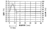
図6は、実施例における上部プレート21の温度制御を示すグラフである。図6の横軸は経過時間を示し、縦軸は上部プレート21の温度および温度調整部30の出力率を示す。また、図6においては、上部プレート21の温度変化を実線で示し、算出された出力率を点線で示し、実際の制御で用いられる出力率(以下、実際の出力率と呼ぶ。)を一点鎖線で示す。
FIG. 6 is a graph showing temperature control of the
図6に示すように、初期時点で基板Wが上部プレート21に載置される。それにより、実線で示すように、上部プレート21の温度が設定温度から上昇する。そこで、上部プレート21の温度変化を抑制するためにフィードバック制御が行われる。この場合、点線で示すように、算出された温度調整部30の出力率が上昇する。同様に、一点鎖線で示すように、実際の出力率も上昇する。なお、実施例におけるフィードバック制御はPID制御であり、実施例におけるPID制御のゲインは比較例1におけるPID制御のゲインと等しい。
As shown in FIG. 6, the substrate W is placed on the
ここで、算出された出力率がしきい値(本例では70%)以上になると、温度制御がフィードバック制御からフィードフォワード制御に切り換えられ、実際の出力率は100%となる。この場合、通常のフィードバック制御よりも高い出力で上部プレート21の冷却処理が行われる。これにより、実線で示すように、上部プレート21の温度は急激に低下する。
Here, when the calculated output rate becomes equal to or greater than a threshold value (70% in this example), the temperature control is switched from feedback control to feedforward control, and the actual output rate becomes 100%. In this case, the cooling process of the
その後、一点鎖線で示すように、実際の出力率は、上部プレート21の温度変化に応じて低下する。算出された出力率がしきい値未満になると、温度制御がフィードフォワード制御からフィードバック制御に切り換えられ、実際の出力率と算出された出力率とが一致する。この場合、通常のフィードバック制御により、実線で示すように、上部プレート21の温度は、設定温度近傍で収束する。また、一点鎖線で示すように、実際の出力率および算出された出力率は、上部プレート21の温度変化に応じて一定値に収束する。
Thereafter, as indicated by the alternate long and short dash line, the actual output rate decreases according to the temperature change of the
実施例では、上部プレート21の温度のオーバーシュートおよびアンダーシュートはほとんど発生せず、基板Wが上部プレート21にされてから比較的短時間(本例では11.5秒)で上部プレート21の温度が設定温度に戻る。このように、上記の制御によれば、通常のフィードバック制御と比較して、即応性および安定性が向上する。
In the embodiment, the temperature overshoot and undershoot of the temperature of the
(3)効果
本実施の形態に係る熱処理装置100においては、出力率がしきい値未満である場合には、上部プレート21の温度を設定温度に維持するために算出された出力率を温度調整部30に与えるフィードバック制御が行われる。これにより、上部プレート21の温度が設定温度に維持される。
(3) Effects In the
一方、出力率がしきい値以上に上昇した場合には、100%の出力率を温度調整部30に与えるフィードフォワード制御が行われる。これにより、上部プレート21の温度が短時間で設定温度に戻される。出力率がしきい値未満まで低下すると、フィードバック制御が行われる。フィードバック制御においては、上部プレート21の温度変化は緩やかであるため、大きなオーバーシュートおよびアンダーシュートは発生しない。
On the other hand, when the output rate rises above the threshold value, feedforward control for giving a 100% output rate to the
この構成によれば、フィードバック制御およびフィードフォワード制御の切り替えにより、制御の即応性および安定性を向上させることができる。その結果、簡単な制御により基板Wの熱処理を正確にかつ高効率で行うことができる。 According to this configuration, it is possible to improve control responsiveness and stability by switching between feedback control and feedforward control. As a result, the heat treatment of the substrate W can be performed accurately and with high efficiency by simple control.
(4)他の実施の形態
(a)上記実施の形態において、プレート部20は基板Wを冷却処理するクーリングプレートであるが、本発明はこれに限定されない。プレート部20は基板Wを加熱処理するホットプレートであってもよい。この場合、熱処理部23の各温調素子23aは、加熱面が上部プレート21に接触しかつ冷却面が下部プレート22に接触するように配置される。あるいは、温調素子23aはペルチェ素子ではなくヒータであってもよい。
(4) Other Embodiments (a) In the above embodiment, the
あるいは、温調素子23aは、純水等の熱媒体を循環させる配管であってもよい。この場合、温度調整部30は配管に熱媒体を供給する熱媒体供給部である。
Alternatively, the
(b)上記実施の形態において、算出された出力率がしきい値以上である場合には、温度調整部30の最大出力が熱処理部23に供給されることが好ましいが、本発明はこれに限定されない。算出された出力率がしきい値以上である場合には、当該しきい値よりも十分に大きな出力が熱処理部23に供給されてもよい。この場合、上部プレート21の温度制御に関する情報として、算出された出力率がしきい値以上であるときに熱処理部23に供給する出力が記憶部11に予め記憶されている。
(B) In the above embodiment, when the calculated output rate is equal to or greater than the threshold value, it is preferable that the maximum output of the
(c)上記実施の形態において、フィードバック制御がフィードフォワード制御に切り換わる際のしきい値とフィードフォワード制御がフィードバック制御に切り換わる際のしきい値とが等しいことが好ましいが、本発明はこれに限定されない。フィードバック制御がフィードフォワード制御に切り換わる際のしきい値とフィードフォワード制御がフィードバック制御に切り換わる際のしきい値とが異なってもよい。この場合、上部プレート21の温度制御に関する情報として、2つのしきい値が記憶部11に予め記憶されている。
(C) In the above embodiment, it is preferable that the threshold value when the feedback control is switched to the feedforward control is equal to the threshold value when the feedforward control is switched to the feedback control. It is not limited to. The threshold value when the feedback control is switched to the feedforward control may be different from the threshold value when the feedforward control is switched to the feedback control. In this case, two threshold values are stored in advance in the
(d)上記実施の形態において、温度調整部30に与えられるべき制御値として、相対値である出力率が算出されることが好ましいが、本発明はこれに限定されない。温度調整部30に与えられるべき制御値として、絶対値である出力量が算出されてもよい。
(D) In the above-described embodiment, it is preferable that the output rate, which is a relative value, is calculated as the control value to be given to the
(5)請求項の各構成要素と実施の形態の各要素との対応関係
以下、請求項の各構成要素と実施の形態の各要素との対応の例について説明するが、本発明は下記の例に限定されない。
(5) Correspondence between each constituent element of claim and each element of the embodiment Hereinafter, an example of correspondence between each constituent element of the claim and each element of the embodiment will be described. It is not limited to examples.
上記実施の形態では、基板Wが基板の例であり、熱処理装置100が熱処理装置の例であり、上部プレート21がプレートの例であり、熱処理部23が熱処理部の例であり、温度調整部30が温度調整部の例である。温度検出部50が温度検出部の例であり、演算処理部14が制御値算出部の例であり、出力制御部15が制御切替部の例であり、温調素子23aがペルチェ素子の例である。
In the above embodiment, the substrate W is an example of a substrate, the
請求項の各構成要素として、請求項に記載されている構成または機能を有する他の種々の要素を用いることもできる。 As each constituent element in the claims, various other elements having configurations or functions described in the claims can be used.
本発明は、種々の基板の熱処理に有効に利用することができる。 The present invention can be effectively used for heat treatment of various substrates.
10 制御装置
11 記憶部
12 昇降制御部
13 温度算出部
14 演算処理部
15 出力制御部
20 プレート部
21 上部プレート
21h,22h 開口部
22 下部プレート
23 熱処理部
23a 温調素子
30 温度調整部
40 昇降装置
41 昇降ピン
42 ピン駆動部
50 温度検出部
100 熱処理装置
W 基板
DESCRIPTION OF
Claims (6)
基板が載置されるプレートと、
前記プレートを冷却または加熱するように配置される熱処理部と、
前記熱処理部の温度を調整する温度調整部と、
前記プレートの温度を検出する温度検出部と、
前記温度検出部により検出された温度に基づいて、前記プレートの温度を設定された値に維持するために前記温度調整部に与えられるべき制御値を制御演算値として算出する制御値算出部と、
前記制御値算出部により算出された制御演算値を前記温度調整部に与える第1の制御と、前記制御値算出部により算出された制御演算値よりも高い制御設定値を前記温度調整部に与える第2の制御とを行う制御切替部とを備え、
前記制御切替部は、前記制御値算出部により算出された制御演算値が第1のしきい値以上に上昇した場合には、前記第1の制御を第2の制御に切り替え、前記制御値算出部により算出された制御演算値が第2のしきい値未満に低下した場合には、前記第2の制御を前記第1の制御に切り替える、熱処理装置。 A heat treatment apparatus for performing heat treatment on a substrate,
A plate on which the substrate is placed;
A heat treatment portion arranged to cool or heat the plate;
A temperature adjusting unit for adjusting the temperature of the heat treatment unit;
A temperature detector for detecting the temperature of the plate;
Based on the temperature detected by the temperature detection unit, a control value calculation unit that calculates a control value to be given to the temperature adjustment unit in order to maintain the temperature of the plate at a set value;
A first control that provides the temperature adjustment unit with the control calculation value calculated by the control value calculation unit, and a control setting value that is higher than the control calculation value calculated by the control value calculation unit is provided to the temperature adjustment unit. A control switching unit that performs the second control,
The control switching unit switches the first control to the second control when the control calculation value calculated by the control value calculation unit rises to a first threshold value or more, and calculates the control value. The heat processing apparatus which switches a said 2nd control to a said 1st control, when the control calculation value calculated by the part falls below the 2nd threshold value.
基板が載置されるプレートを熱処理部により冷却または加熱するステップと、
前記熱処理部の温度を温度調整部により調整するステップと、
前記プレートの温度を検出するステップと、
検出された温度に基づいて、前記プレートの温度を設定された値に維持するために前記温度調整部に与えられるべき制御値を制御演算値として算出するステップと、
算出された制御演算値を前記温度調整部に与える第1の制御と、算出された制御演算値よりも高い制御設定値を前記温度調整部に与える第2の制御とを行うステップとを含み、
前記第1の制御と前記第2の制御とを行うステップは、算出された制御演算値が第1のしきい値以上に上昇した場合には、第1の制御を第2の制御に切り替え、算出された制御演算値が第2のしきい値未満に低下した場合には、前記第2の制御を前記第1の制御に切り替えることを含む、熱処理方法。 A heat treatment method for performing heat treatment on a substrate,
Cooling or heating the plate on which the substrate is placed by a heat treatment unit;
Adjusting the temperature of the heat treatment part by a temperature adjustment part;
Detecting the temperature of the plate;
Calculating a control value to be given to the temperature adjustment unit as a control calculation value in order to maintain the temperature of the plate at a set value based on the detected temperature;
Performing a first control for giving the calculated control calculation value to the temperature adjustment unit, and a second control for giving a control set value higher than the calculated control calculation value to the temperature adjustment unit,
The step of performing the first control and the second control includes switching the first control to the second control when the calculated control calculation value rises above the first threshold value. If the calculated control operation value drops below the second threshold comprises switching the second control to the first control, a heat treatment method.
Priority Applications (6)
| Application Number | Priority Date | Filing Date | Title |
|---|---|---|---|
| JP2015063949A JP6442339B2 (en) | 2015-03-26 | 2015-03-26 | Heat treatment apparatus and heat treatment method |
| KR1020177026625A KR101994570B1 (en) | 2015-03-26 | 2015-11-17 | Heat treatment apparatus and heat treatment method |
| CN201580077665.5A CN107430985B (en) | 2015-03-26 | 2015-11-17 | Heat treatment apparatus and heat treatment method |
| PCT/JP2015/005727 WO2016151651A1 (en) | 2015-03-26 | 2015-11-17 | Heat treatment device and heat treatment method |
| US15/556,919 US10629463B2 (en) | 2015-03-26 | 2015-11-17 | Thermal processing apparatus and thermal processing method |
| TW105101214A TWI644342B (en) | 2015-03-26 | 2016-01-15 | Thermal processing apparatus and thermal processing method |
Applications Claiming Priority (1)
| Application Number | Priority Date | Filing Date | Title |
|---|---|---|---|
| JP2015063949A JP6442339B2 (en) | 2015-03-26 | 2015-03-26 | Heat treatment apparatus and heat treatment method |
Publications (3)
| Publication Number | Publication Date |
|---|---|
| JP2016183815A JP2016183815A (en) | 2016-10-20 |
| JP2016183815A5 JP2016183815A5 (en) | 2018-03-22 |
| JP6442339B2 true JP6442339B2 (en) | 2018-12-19 |
Family
ID=56977144
Family Applications (1)
| Application Number | Title | Priority Date | Filing Date |
|---|---|---|---|
| JP2015063949A Active JP6442339B2 (en) | 2015-03-26 | 2015-03-26 | Heat treatment apparatus and heat treatment method |
Country Status (6)
| Country | Link |
|---|---|
| US (1) | US10629463B2 (en) |
| JP (1) | JP6442339B2 (en) |
| KR (1) | KR101994570B1 (en) |
| CN (1) | CN107430985B (en) |
| TW (1) | TWI644342B (en) |
| WO (1) | WO2016151651A1 (en) |
Families Citing this family (4)
| Publication number | Priority date | Publication date | Assignee | Title |
|---|---|---|---|---|
| JP6872914B2 (en) * | 2017-01-30 | 2021-05-19 | 株式会社Screenホールディングス | Heat treatment equipment and heat treatment method |
| IT201800020272A1 (en) * | 2018-12-20 | 2020-06-20 | Amx Automatrix S R L | SINTERING PRESS FOR SINTERING ELECTRONIC COMPONENTS ON A SUBSTRATE |
| JP7256034B2 (en) * | 2019-03-04 | 2023-04-11 | 株式会社Screenホールディングス | Heat treatment apparatus and heat treatment method |
| JP7198718B2 (en) * | 2019-04-26 | 2023-01-04 | 株式会社Screenホールディングス | Heat treatment apparatus and heat treatment method |
Family Cites Families (23)
| Publication number | Priority date | Publication date | Assignee | Title |
|---|---|---|---|---|
| JPH07115058A (en) | 1993-10-18 | 1995-05-02 | Dainippon Screen Mfg Co Ltd | Board cooling device |
| US5638687A (en) | 1994-11-21 | 1997-06-17 | Dainippon Screen Mfg. Co., Ltd. | Substrate cooling method and apparatus |
| JPH08148421A (en) | 1994-11-21 | 1996-06-07 | Dainippon Screen Mfg Co Ltd | Substrate cooler |
| JPH08203796A (en) | 1995-01-30 | 1996-08-09 | Dainippon Screen Mfg Co Ltd | Substrate cooling device |
| JPH08236414A (en) * | 1995-02-27 | 1996-09-13 | Dainippon Screen Mfg Co Ltd | Substrate cooler |
| JP3504018B2 (en) * | 1995-03-31 | 2004-03-08 | 大日本スクリーン製造株式会社 | Substrate cooling device |
| JP3665826B2 (en) * | 1997-05-29 | 2005-06-29 | Smc株式会社 | Substrate heat treatment equipment |
| US6230497B1 (en) * | 1999-12-06 | 2001-05-15 | Motorola, Inc. | Semiconductor circuit temperature monitoring and controlling apparatus and method |
| US6191399B1 (en) * | 2000-02-01 | 2001-02-20 | Asm America, Inc. | System of controlling the temperature of a processing chamber |
| WO2004038776A1 (en) | 2002-10-25 | 2004-05-06 | Tokyo Electron Limited | Heat treatment system and heat treatment method |
| JP4384538B2 (en) * | 2003-06-16 | 2009-12-16 | 東京エレクトロン株式会社 | Substrate processing apparatus and substrate processing method |
| JP5040213B2 (en) | 2006-08-15 | 2012-10-03 | 東京エレクトロン株式会社 | Heat treatment apparatus, heat treatment method and storage medium |
| JP5041016B2 (en) | 2010-03-01 | 2012-10-03 | 東京エレクトロン株式会社 | Heat treatment apparatus, heat treatment method and storage medium |
| JP5048810B2 (en) | 2010-06-23 | 2012-10-17 | 東京エレクトロン株式会社 | Heat treatment apparatus and heat treatment method |
| JP2012080080A (en) | 2010-09-07 | 2012-04-19 | Tokyo Electron Ltd | Vertical heat treatment apparatus and control method therefor |
| KR101512874B1 (en) | 2010-09-07 | 2015-04-16 | 도쿄엘렉트론가부시키가이샤 | Vertical heat processing apparatus and control method of the same |
| US9316424B2 (en) | 2011-04-19 | 2016-04-19 | Liebert Corporation | Multi-stage cooling system with tandem compressors and optimized control of sensible cooling and dehumidification |
| US9845981B2 (en) | 2011-04-19 | 2017-12-19 | Liebert Corporation | Load estimator for control of vapor compression cooling system with pumped refrigerant economization |
| US9038404B2 (en) * | 2011-04-19 | 2015-05-26 | Liebert Corporation | High efficiency cooling system |
| JP5708310B2 (en) | 2011-07-01 | 2015-04-30 | 東京エレクトロン株式会社 | Substrate processing equipment |
| JP2013062361A (en) | 2011-09-13 | 2013-04-04 | Tokyo Electron Ltd | Heat treatment apparatus, temperature control system, heat treatment method, temperature control method, and record medium recording program for executing heat treatment method or temperature control method |
| JP5951438B2 (en) | 2012-10-05 | 2016-07-13 | 光洋サーモシステム株式会社 | Heat treatment equipment |
| JP6064613B2 (en) | 2013-01-18 | 2017-01-25 | 株式会社ノーリツ | Water heater |
-
2015
- 2015-03-26 JP JP2015063949A patent/JP6442339B2/en active Active
- 2015-11-17 CN CN201580077665.5A patent/CN107430985B/en active Active
- 2015-11-17 KR KR1020177026625A patent/KR101994570B1/en active IP Right Grant
- 2015-11-17 WO PCT/JP2015/005727 patent/WO2016151651A1/en active Application Filing
- 2015-11-17 US US15/556,919 patent/US10629463B2/en active Active
-
2016
- 2016-01-15 TW TW105101214A patent/TWI644342B/en active
Also Published As
| Publication number | Publication date |
|---|---|
| TWI644342B (en) | 2018-12-11 |
| KR101994570B1 (en) | 2019-06-28 |
| JP2016183815A (en) | 2016-10-20 |
| US20180033660A1 (en) | 2018-02-01 |
| WO2016151651A1 (en) | 2016-09-29 |
| CN107430985B (en) | 2020-10-30 |
| TW201637077A (en) | 2016-10-16 |
| CN107430985A (en) | 2017-12-01 |
| US10629463B2 (en) | 2020-04-21 |
| KR20170120151A (en) | 2017-10-30 |
Similar Documents
| Publication | Publication Date | Title |
|---|---|---|
| JP6442339B2 (en) | Heat treatment apparatus and heat treatment method | |
| US6461438B1 (en) | Heat treatment unit, cooling unit and cooling treatment method | |
| JP3665826B2 (en) | Substrate heat treatment equipment | |
| US9818624B2 (en) | Methods and apparatus for correcting substrate deformity | |
| KR20020065398A (en) | Inertial temperature control system and method | |
| KR100772270B1 (en) | Rapid thermal processing apparatus and method for preventing warp of wafer | |
| JP3838208B2 (en) | Semiconductor wafer heat treatment apparatus and method | |
| JPH1174187A (en) | Substrate thermal treatment method and apparatus | |
| TW201535524A (en) | Adaptive baking system, method of using the same, and controller for the same | |
| JP7027198B2 (en) | Board processing equipment | |
| JP7198718B2 (en) | Heat treatment apparatus and heat treatment method | |
| JPH08236533A (en) | Wafer heating/cooling device | |
| JPH09306978A (en) | Temp. control of substrate, substrate heat treating apparatus and substrate supporting apparatus | |
| TWI772745B (en) | Thermal processing apparatus and thermal processing method | |
| JP3648150B2 (en) | Cooling processing apparatus and cooling processing method | |
| JP4739132B2 (en) | Heat treatment apparatus and heat treatment method | |
| JP2744985B2 (en) | Resist processing equipment | |
| JP3504018B2 (en) | Substrate cooling device | |
| JPH08236414A (en) | Substrate cooler | |
| JPH08148421A (en) | Substrate cooler | |
| JP6872914B2 (en) | Heat treatment equipment and heat treatment method | |
| JP2006313779A (en) | Heat treatment apparatus and method | |
| JP2000183071A (en) | Substrate heat-treatment apparatus | |
| KR20240022689A (en) | Substrate processing method and substrate processing apparatus | |
| TW202044411A (en) | Thermal processing apparatus, thermal processing system and thermal processing method |
Legal Events
| Date | Code | Title | Description |
|---|---|---|---|
| A621 | Written request for application examination |
Free format text: JAPANESE INTERMEDIATE CODE: A621 Effective date: 20171222 |
|
| A521 | Request for written amendment filed |
Free format text: JAPANESE INTERMEDIATE CODE: A523 Effective date: 20180207 |
|
| TRDD | Decision of grant or rejection written | ||
| A01 | Written decision to grant a patent or to grant a registration (utility model) |
Free format text: JAPANESE INTERMEDIATE CODE: A01 Effective date: 20181030 |
|
| A61 | First payment of annual fees (during grant procedure) |
Free format text: JAPANESE INTERMEDIATE CODE: A61 Effective date: 20181126 |
|
| R150 | Certificate of patent or registration of utility model |
Ref document number: 6442339 Country of ref document: JP Free format text: JAPANESE INTERMEDIATE CODE: R150 |
|
| R250 | Receipt of annual fees |
Free format text: JAPANESE INTERMEDIATE CODE: R250 |
|
| R250 | Receipt of annual fees |
Free format text: JAPANESE INTERMEDIATE CODE: R250 |
|
| R250 | Receipt of annual fees |
Free format text: JAPANESE INTERMEDIATE CODE: R250 |