JP6437656B2 - Storage device, storage system, and storage system control method - Google Patents
Storage device, storage system, and storage system control method Download PDFInfo
- Publication number
- JP6437656B2 JP6437656B2 JP2017532241A JP2017532241A JP6437656B2 JP 6437656 B2 JP6437656 B2 JP 6437656B2 JP 2017532241 A JP2017532241 A JP 2017532241A JP 2017532241 A JP2017532241 A JP 2017532241A JP 6437656 B2 JP6437656 B2 JP 6437656B2
- Authority
- JP
- Japan
- Prior art keywords
- storage
- storage device
- management information
- memory
- cache
- Prior art date
- Legal status (The legal status is an assumption and is not a legal conclusion. Google has not performed a legal analysis and makes no representation as to the accuracy of the status listed.)
- Active
Links
Images


Classifications
-
- G—PHYSICS
- G06—COMPUTING; CALCULATING OR COUNTING
- G06F—ELECTRIC DIGITAL DATA PROCESSING
- G06F11/00—Error detection; Error correction; Monitoring
- G06F11/07—Responding to the occurrence of a fault, e.g. fault tolerance
- G06F11/16—Error detection or correction of the data by redundancy in hardware
- G06F11/20—Error detection or correction of the data by redundancy in hardware using active fault-masking, e.g. by switching out faulty elements or by switching in spare elements
- G06F11/2053—Error detection or correction of the data by redundancy in hardware using active fault-masking, e.g. by switching out faulty elements or by switching in spare elements where persistent mass storage functionality or persistent mass storage control functionality is redundant
- G06F11/2094—Redundant storage or storage space
-
- G—PHYSICS
- G06—COMPUTING; CALCULATING OR COUNTING
- G06F—ELECTRIC DIGITAL DATA PROCESSING
- G06F11/00—Error detection; Error correction; Monitoring
- G06F11/07—Responding to the occurrence of a fault, e.g. fault tolerance
- G06F11/16—Error detection or correction of the data by redundancy in hardware
- G06F11/1658—Data re-synchronization of a redundant component, or initial sync of replacement, additional or spare unit
- G06F11/1662—Data re-synchronization of a redundant component, or initial sync of replacement, additional or spare unit the resynchronized component or unit being a persistent storage device
-
- G—PHYSICS
- G06—COMPUTING; CALCULATING OR COUNTING
- G06F—ELECTRIC DIGITAL DATA PROCESSING
- G06F11/00—Error detection; Error correction; Monitoring
- G06F11/07—Responding to the occurrence of a fault, e.g. fault tolerance
- G06F11/16—Error detection or correction of the data by redundancy in hardware
- G06F11/1666—Error detection or correction of the data by redundancy in hardware where the redundant component is memory or memory area
-
- G—PHYSICS
- G06—COMPUTING; CALCULATING OR COUNTING
- G06F—ELECTRIC DIGITAL DATA PROCESSING
- G06F12/00—Accessing, addressing or allocating within memory systems or architectures
- G06F12/02—Addressing or allocation; Relocation
- G06F12/08—Addressing or allocation; Relocation in hierarchically structured memory systems, e.g. virtual memory systems
- G06F12/0802—Addressing of a memory level in which the access to the desired data or data block requires associative addressing means, e.g. caches
- G06F12/0806—Multiuser, multiprocessor or multiprocessing cache systems
- G06F12/084—Multiuser, multiprocessor or multiprocessing cache systems with a shared cache
-
- G—PHYSICS
- G06—COMPUTING; CALCULATING OR COUNTING
- G06F—ELECTRIC DIGITAL DATA PROCESSING
- G06F12/00—Accessing, addressing or allocating within memory systems or architectures
- G06F12/02—Addressing or allocation; Relocation
- G06F12/08—Addressing or allocation; Relocation in hierarchically structured memory systems, e.g. virtual memory systems
- G06F12/0802—Addressing of a memory level in which the access to the desired data or data block requires associative addressing means, e.g. caches
- G06F12/0866—Addressing of a memory level in which the access to the desired data or data block requires associative addressing means, e.g. caches for peripheral storage systems, e.g. disk cache
- G06F12/0871—Allocation or management of cache space
-
- G—PHYSICS
- G06—COMPUTING; CALCULATING OR COUNTING
- G06F—ELECTRIC DIGITAL DATA PROCESSING
- G06F3/00—Input arrangements for transferring data to be processed into a form capable of being handled by the computer; Output arrangements for transferring data from processing unit to output unit, e.g. interface arrangements
- G06F3/06—Digital input from, or digital output to, record carriers, e.g. RAID, emulated record carriers or networked record carriers
- G06F3/0601—Interfaces specially adapted for storage systems
- G06F3/0602—Interfaces specially adapted for storage systems specifically adapted to achieve a particular effect
- G06F3/0604—Improving or facilitating administration, e.g. storage management
-
- G—PHYSICS
- G06—COMPUTING; CALCULATING OR COUNTING
- G06F—ELECTRIC DIGITAL DATA PROCESSING
- G06F3/00—Input arrangements for transferring data to be processed into a form capable of being handled by the computer; Output arrangements for transferring data from processing unit to output unit, e.g. interface arrangements
- G06F3/06—Digital input from, or digital output to, record carriers, e.g. RAID, emulated record carriers or networked record carriers
- G06F3/0601—Interfaces specially adapted for storage systems
- G06F3/0602—Interfaces specially adapted for storage systems specifically adapted to achieve a particular effect
- G06F3/061—Improving I/O performance
-
- G—PHYSICS
- G06—COMPUTING; CALCULATING OR COUNTING
- G06F—ELECTRIC DIGITAL DATA PROCESSING
- G06F3/00—Input arrangements for transferring data to be processed into a form capable of being handled by the computer; Output arrangements for transferring data from processing unit to output unit, e.g. interface arrangements
- G06F3/06—Digital input from, or digital output to, record carriers, e.g. RAID, emulated record carriers or networked record carriers
- G06F3/0601—Interfaces specially adapted for storage systems
- G06F3/0602—Interfaces specially adapted for storage systems specifically adapted to achieve a particular effect
- G06F3/0614—Improving the reliability of storage systems
-
- G—PHYSICS
- G06—COMPUTING; CALCULATING OR COUNTING
- G06F—ELECTRIC DIGITAL DATA PROCESSING
- G06F3/00—Input arrangements for transferring data to be processed into a form capable of being handled by the computer; Output arrangements for transferring data from processing unit to output unit, e.g. interface arrangements
- G06F3/06—Digital input from, or digital output to, record carriers, e.g. RAID, emulated record carriers or networked record carriers
- G06F3/0601—Interfaces specially adapted for storage systems
- G06F3/0628—Interfaces specially adapted for storage systems making use of a particular technique
- G06F3/0646—Horizontal data movement in storage systems, i.e. moving data in between storage devices or systems
- G06F3/065—Replication mechanisms
-
- G—PHYSICS
- G06—COMPUTING; CALCULATING OR COUNTING
- G06F—ELECTRIC DIGITAL DATA PROCESSING
- G06F3/00—Input arrangements for transferring data to be processed into a form capable of being handled by the computer; Output arrangements for transferring data from processing unit to output unit, e.g. interface arrangements
- G06F3/06—Digital input from, or digital output to, record carriers, e.g. RAID, emulated record carriers or networked record carriers
- G06F3/0601—Interfaces specially adapted for storage systems
- G06F3/0628—Interfaces specially adapted for storage systems making use of a particular technique
- G06F3/0662—Virtualisation aspects
- G06F3/0665—Virtualisation aspects at area level, e.g. provisioning of virtual or logical volumes
-
- G—PHYSICS
- G06—COMPUTING; CALCULATING OR COUNTING
- G06F—ELECTRIC DIGITAL DATA PROCESSING
- G06F3/00—Input arrangements for transferring data to be processed into a form capable of being handled by the computer; Output arrangements for transferring data from processing unit to output unit, e.g. interface arrangements
- G06F3/06—Digital input from, or digital output to, record carriers, e.g. RAID, emulated record carriers or networked record carriers
- G06F3/0601—Interfaces specially adapted for storage systems
- G06F3/0668—Interfaces specially adapted for storage systems adopting a particular infrastructure
- G06F3/0671—In-line storage system
- G06F3/0683—Plurality of storage devices
-
- G—PHYSICS
- G06—COMPUTING; CALCULATING OR COUNTING
- G06F—ELECTRIC DIGITAL DATA PROCESSING
- G06F11/00—Error detection; Error correction; Monitoring
- G06F11/07—Responding to the occurrence of a fault, e.g. fault tolerance
- G06F11/16—Error detection or correction of the data by redundancy in hardware
- G06F11/1658—Data re-synchronization of a redundant component, or initial sync of replacement, additional or spare unit
-
- G—PHYSICS
- G06—COMPUTING; CALCULATING OR COUNTING
- G06F—ELECTRIC DIGITAL DATA PROCESSING
- G06F2212/00—Indexing scheme relating to accessing, addressing or allocation within memory systems or architectures
- G06F2212/10—Providing a specific technical effect
- G06F2212/1016—Performance improvement
- G06F2212/1024—Latency reduction
-
- G—PHYSICS
- G06—COMPUTING; CALCULATING OR COUNTING
- G06F—ELECTRIC DIGITAL DATA PROCESSING
- G06F3/00—Input arrangements for transferring data to be processed into a form capable of being handled by the computer; Output arrangements for transferring data from processing unit to output unit, e.g. interface arrangements
- G06F3/06—Digital input from, or digital output to, record carriers, e.g. RAID, emulated record carriers or networked record carriers
- G06F3/0601—Interfaces specially adapted for storage systems
- G06F3/0628—Interfaces specially adapted for storage systems making use of a particular technique
- G06F3/0646—Horizontal data movement in storage systems, i.e. moving data in between storage devices or systems
Description
本発明は、ストレージ装置、ストレージシステム、ストレージシステムの制御方法に関する。 The present invention relates to a storage apparatus, a storage system, and a storage system control method.
本技術分野の背景技術として、特開2006−221526号公報(特許文献1)に記載の技術がある。この公報には、複数のメモリを有するストレージ装置において、管理情報を異なるメモリ間で冗長化し、管理情報を格納するメモリに障害が発生したとき、他のメモリに管理情報をコピーして冗長性を確保する技術について記載されている。 As a background art of this technical field, there is a technique described in JP-A-2006-221526 (Patent Document 1). In this publication, in a storage apparatus having a plurality of memories, management information is made redundant between different memories, and when a failure occurs in a memory storing the management information, the management information is copied to another memory to provide redundancy. It describes the technology to be secured.
企業等がビジネスを遂行するための業務データを保存するストレージシステムについて、ビジネスの変化にあわせてシステム規模を柔軟に変更するため、複数のストレージ装置を連携させてシステムを構築したいという要求がある。例えば、システム導入時は当面必要となるストレージリソースを備えるストレージ装置でシステムを構築し、ビジネスが成長してストレージリソースの利用量が増加してきたら、既存のストレージ装置を活用しつつストレージ装置を増設することで、システム全体のストレージリソースを拡張することができる。 With respect to storage systems that store business data for companies to conduct business, there is a demand for building a system by linking a plurality of storage devices in order to flexibly change the system scale according to business changes. For example, when a system is installed, build a system with storage devices that have storage resources that will be needed for the time being, and if the amount of storage resources used increases as the business grows, add storage devices while using existing storage devices As a result, the storage resources of the entire system can be expanded.
このように、ストレージシステムを複数のストレージ装置で構築する場合、ストレージシステムの稼動に必要な管理情報を、異なるストレージ装置のメモリ間で冗長化することで、可用性を高めることができる。また、ストレージシステムを構築する一部のストレージ装置で障害が発生したとき、または減設するとき等、当該ストレージ装置の使用を停止する場合、当該ストレージ装置が格納する管理情報を他のストレージ装置にコピーすることで、冗長性を維持することができる。 Thus, when a storage system is constructed with a plurality of storage devices, the management information necessary for the operation of the storage system can be made redundant between the memories of different storage devices, thereby increasing availability. Also, when the use of the storage device is stopped, such as when a failure occurs in some of the storage devices that make up the storage system, or when it is removed, the management information stored in the storage device is transferred to other storage devices. Redundancy can be maintained by copying.
特許文献1では、障害発生時に管理情報をコピーするために、コピー先のメモリに管理情報を格納可能な空き容量を確保する必要がある。しかし、コピー先のストレージ装置において、当該管理情報を格納可能な空き容量を定常的に確保する場合、通常時のメモリの使用率が低下して、コストが高くなる。これに対し、コピー先のストレージ装置に当該管理情報を格納可能な空き容量を動的に確保する場合、通常時のメモリの使用率は向上するが、動的に空き容量を確保した時のシステムへの影響を低減する必要がある。そのため、各ストレージ装置で個別に管理されるメモリの使用状態をふまえて、コピー先のストレージ装置を適切に決めることが重要である。
In
そこで、ストレージ装置の使用を停止する場合に備えて、当該ストレージ装置の管理情報を格納するための空き容量を、他のストレージ装置のメモリに定常的に確保しなくても、当該ストレージ装置の使用を停止するときに動的に空き容量を確保可能にし、また動的に空き容量を確保したときのシステムへの影響を低減可能なストレージシステムを提供する。 Therefore, in preparation for stopping the use of the storage device, the storage device can be used even if the free space for storing the management information of the storage device is not constantly secured in the memory of the other storage device. It is possible to provide a storage system capable of dynamically securing a free capacity when stopping the storage and reducing the influence on the system when the free capacity is dynamically secured.
上記課題を解決するために、本発明のストレージシステムは、第1ストレージ装置を含む複数のストレージ装置を備える。複数のストレージ装置の其々は、管理情報を格納する管理情報格納領域とキャッシュ情報を格納するキャッシュ領域とを有するメモリと、キャッシュ領域の状態を管理するプロセッサと、を備える。第1ストレージ装置のメモリの使用を停止するとき、複数のストレージ装置の少なくとも一部のプロセッサは、第1ストレージ装置以外のストレージ装置が其々管理するキャッシュ領域の状態に基づいて、使用を停止するメモリが格納する管理情報であるコピー対象管理情報のコピー先となるコピー先ストレージ装置を決定する。コピー先ストレージ装置のプロセッサは、コピー先ストレージ装置のメモリのキャッシュ領域の少なくとも一部を解放して、解放したキャッシュ領域に、コピー対象管理情報を格納する。 In order to solve the above problems, a storage system of the present invention includes a plurality of storage apparatuses including a first storage apparatus. Each of the plurality of storage apparatuses includes a memory having a management information storage area for storing management information and a cache area for storing cache information, and a processor for managing the state of the cache area. When stopping the use of the memory of the first storage device, at least some of the processors of the plurality of storage devices stop using based on the state of the cache area managed by each storage device other than the first storage device. A copy destination storage apparatus that is a copy destination of copy target management information that is management information stored in the memory is determined. The processor of the copy destination storage apparatus releases at least a part of the cache area of the memory of the copy destination storage apparatus, and stores the copy target management information in the released cache area.
ストレージ装置の使用を停止する場合に備えて、当該ストレージ装置の管理情報を格納するための空き容量を、他のストレージ装置のメモリに定常的に確保しなくても、当該ストレージ装置の使用を停止するときに動的に空き容量を確保でき、メモリの使用効率を向上できる。また、動的に空き容量を確保したときのストレージシステムへの影響を低減できる。上記した以外の課題、構成及び効果は、以下の発明を実施するための形態の説明により明らかにされる。 In preparation for stopping the use of a storage device, the use of the storage device is stopped even if the free space for storing the management information of the storage device is not regularly reserved in the memory of another storage device. When this is done, free space can be dynamically secured and the memory usage efficiency can be improved. In addition, it is possible to reduce the influence on the storage system when the free capacity is dynamically secured. Problems, configurations, and effects other than those described above will become apparent from the following description of embodiments for carrying out the invention.
以下、図面を用いて実施例について説明する。 Embodiments will be described below with reference to the drawings.
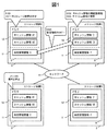
図1は、本実施例における管理情報の退避処理の概念を示す図である。 FIG. 1 is a diagram illustrating a concept of management information saving processing in the present embodiment.
本実施例のストレージシステムは、複数のストレージ装置2が、ネットワーク41を介して接続されている。各ストレージ装置2のメモリ9は、管理情報を格納する管理情報格納領域11と、キャッシュ情報を格納するキャッシュ領域12とを有する。また、各ストレージ装置2のプロセッサ8は、当該ストレージ装置2のキャッシュ領域12のアクセス頻度を管理している。
In the storage system of this embodiment, a plurality of
管理情報は、複数のストレージ装置2が稼動しているとき、複数のストレージ装置2のメモリ9の少なくともいずれかに格納され、複数のストレージ装置2の少なくともいずれかのプロセッサ8が当該メモリ9から参照可能な情報である。特に、各ストレージ装置2が稼動しているとき、当該ストレージ装置2のプロセッサ8は、当該ストレージ装置2のメモリ9に格納された管理情報を参照できる。
The management information is stored in at least one of the
キャッシュ情報は、複数のストレージ装置2が稼動しているとき、複数のストレージ装置2の少なくともいずれかが備える記憶デバイス(ドライブ4)に同じデータが格納されている場合、複数のストレージ装置2のいずれのメモリ9からも削除可能な情報である。特に、各ストレージ装置2が稼動しているとき、当該ストレージ装置2が備える記憶デバイス(ドライブ4)に格納されたデータと同じデータであるキャッシュ情報は、メモリ9のキャッシュ領域12から削除しても良い。ここで、削除とは、他のキャッシュ情報で上書きすること、当該キャッシュ情報を消失すること、当該キャッシュ情報にアクセス不能にすることのいずれであっても良い。
When the same data is stored in the storage device (drive 4) included in at least one of the plurality of
図1では、複数のストレージ装置2の例として、ストレージ装置A、B、C、Dが示されている。ただし、ストレージシステムを構成するストレージ装置2の数はこの例に限定されず、少なくとも2以上のストレージ装置2であれば良い。
In FIG. 1, storage apparatuses A, B, C, and D are shown as examples of the plurality of
ストレージ装置A及びストレージ装置Bそれぞれのメモリ9の管理情報格納領域11は、同一の共有管理情報Xを格納しており、この共有管理情報Xを冗長化している。このように、異なるストレージ装置2の間で管理情報の冗長性をもたせることで、一方のストレージ装置2で障害が発生してメモリ9が使用不能になったとしても、他方のストレージ装置2のメモリ9に格納された管理情報を用いて、運用が継続可能となり、可用性を高めることができる。
The management
以下、ストレージ装置Bのメモリ9の使用を停止する場合に、ストレージシステムで実行される管理情報の退避処理の例を説明する。ストレージ装置Bのメモリ9の使用を停止すると、共有管理情報Xの冗長性が失われ、信頼性が低下してしまう。そこで、本処理により、ストレージ装置A、B以外のストレージ装置C、Dの少なくともいずれかに共有管理情報Xをコピーすることで冗長化し、信頼性を回復する。ここで、ストレージ装置2のメモリ9の使用を停止するときとは、典型的にはストレージ装置2の使用を停止するときであり、例えば当該ストレージ装置2で障害が発生したときや、ストレージ装置2を減設するときである。例えば、ストレージシステムを構成する複数のストレージ装置2から一部のストレージ装置2を減設することで、運用管理コストが削減可能となる。この使用を停止するメモリ9に格納された共有管理情報Xを、コピー対象管理情報とも呼ぶ。
Hereinafter, an example of management information saving processing executed in the storage system when the use of the
ストレージ装置Bのメモリ9の使用を停止するとき、例えば、当該ストレージ装置Bと共有管理情報Xを冗長化しているストレージ装置Aが、ストレージ装置Bのメモリ9の使用停止を検知する。これは、ストレージ装置Aが定期的または不定期にストレージ装置Bにアクセスすることで検知しても良いし、ストレージシステムに接続する管理端末からの指示に基づいて検知しても良い。
When stopping the use of the
ストレージ装置A、B以外のストレージ装置C、Dが、共有管理情報Xのコピー先候補となるコピー先候補ストレージ装置である。以下の例では、コピー先候補ストレージ装置のいずれのメモリ9も、管理情報(共有管理情報Y等)とキャッシュ情報(キャッシュ情報C1、C2、D1、D2等)が格納されており、共有管理情報Xを格納するための空き容量がないとする。コピー先候補ストレージ装置に、他のストレージ装置2の管理情報(共有管理情報X)を格納するための空き容量を定常的に確保せず、例えばその代わりにキャッシュ領域12を多く確保することで、メモリ9の使用効率を向上できる。
The storage devices C and D other than the storage devices A and B are copy destination candidate storage devices that are copy destination candidates for the share management information X. In the following example, management information (such as shared management information Y) and cache information (cache information C1, C2, D1, D2, etc.) are stored in any
本実施例では、コピー先候補ストレージ装置のいずれかのメモリ9の情報を削除して、共有管理情報Xを格納する。管理情報はストレージシステムの動作に必要な情報であり削除できないため、キャッシュ情報を削除する。ストレージ装置2のメモリ9のキャッシュ領域12は、ホスト計算機1からのデータアクセス要求時の応答性能を高速化するために、キャッシュ情報(キャッシュデータ)が格納されており、コピーが必要な管理情報を格納するための容量が空いていないことが多い。キャッシュ領域12には、アクセス頻度の高いキャッシュ領域とアクセス頻度の低いキャッシュ領域とが混在している。このため、無作為にキャッシュ情報を削除してキャッシュ領域を解放すると、キャッシュヒット率が低下してアクセス性能が大きく低下する。本実施例では、アクセス性能をキャッシュヒット率とし、アクセス性能の低下量をキャッシュヒット率の低下量として説明する。ただし、アクセス性能及びアクセス性能の低下量は、この例に限定されない。
In this embodiment, the information in any
そこで、キャッシュヒット率の低下量が小さくなるように、キャッシュ領域12のアクセス頻度に基づいて、少なくとも一部のキャッシュ領域12を解放する。これにより、あらかじめメモリ容量の空きを確保していなくても、ストレージ装置2の障害時または減設時等に、当該ストレージ装置2の管理情報を他のストレージ装置2のメモリ9に格納可能になる。
Therefore, at least a part of the
以下の説明では、コピー先候補ストレージ装置のいずれか一つに、一つのコピー対象管理情報である共有管理情報Xを格納する例を示す。しかし、コピー対象管理情報が複数あって、異なるストレージ装置2に分けて格納可能な場合においては、コピー対象管理情報毎に以下の処理を実行しても良い。その場合、容量の大きいコピー対象管理情報から優先的に、コピー先ストレージ装置を決定しても良い。
In the following description, an example is shown in which the shared management information X, which is one copy target management information, is stored in any one of the copy destination candidate storage devices. However, when there are a plurality of pieces of copy target management information and can be stored separately in
まず、ストレージ装置Aは、コピー先候補ストレージ装置C、Dの其々に、共有管理情報Xの容量を通知する。コピー先候補ストレージ装置C、Dは、各々が個別に管理するキャッシュ領域12のアクセス頻度に基づいて、共有管理情報Xをコピーした場合のアクセス性能の低下量を予測して、ストレージ装置Aに予測した低下量を送信する。ストレージ装置Aは、コピー先候補ストレージ装置C、D其々で予測した低下量に基づき、前記予測したアクセス性能の低下量の低いコピー先候補ストレージ装置を、前記コピー先ストレージ装置に決定する(S100)。これにより、キャッシュ領域を解放したときにおけるシステム全体のアクセス頻度への影響を小さくできる。図1の例では、コピー先ストレージ装置は、ストレージ装置Cである。各コピー先候補ストレージ装置C、Dにおけるアクセス性能の低下量予測処理の詳細は、図10を用いて後述する。
First, the storage apparatus A notifies the copy destination candidate storage apparatuses C and D of the capacity of the share management information X, respectively. The copy destination candidate storage apparatuses C and D predict the amount of decrease in access performance when the shared management information X is copied based on the access frequency of the
ここで、コピー先ストレージ装置は、アクセス性能の低下量の低いコピー先候補ストレージ装置とする例について説明したが、必ずしもアクセス性能の低下量だけで決定しなくても良い。例えば、複数のコピー先候補ストレージ装置のうち、コピー対象管理情報が優先的に配置されるストレージ装置2がある場合は、その優先順位に基づいて、コピー先ストレージ装置を決定しても良い。この場合、各コピー先候補ストレージ装置から、必要な情報を取得しても良い。例えば、プロセッサ8が高負荷のストレージ装置2がコピー処理を実施するとアクセス性能が低下する恐れがあるため、各ストレージ装置2のプロセッサ8の負荷を取得し、プロセッサ8の負荷が低いストレージ装置2をコピー先ストレージ装置に決定しても良い。
Here, an example has been described in which the copy destination storage apparatus is a copy destination candidate storage apparatus with a low access performance degradation amount, but it is not always necessary to determine only the access performance degradation amount. For example, when there is a
コピー先ストレージ装置は、コピー先候補ストレージ装置が其々管理するキャッシュ領域12の状態に基づいて、決定されて良い。キャッシュ領域12の状態には、キャッシュ領域12のアクセス頻度の情報を含んでいても良い。キャッシュ領域12の状態として、キャッシュ領域12の最終アクセス時刻185や、使用可能か否かの情報、キャッシュ領域12が使用されているか否かの情報(使用中フラグ183)を含んでいても良い。
The copy destination storage device may be determined based on the state of the
ストレージ装置Aは、コピー先ストレージ装置Cに共有管理情報Xをコピーするための容量を確保するように指示する。コピー先ストレージ装置Cのプロセッサは、共有管理情報Xを格納するキャッシュ領域が連続した領域となるように、アクセス頻度に基づいて、当該コピー先ストレージ装置Cのキャッシュ情報(C1、C2等)の再配置を実行する(S101)。このキャッシュ情報の再配置処理(S101)の詳細は、図11を用いて後述する。 The storage apparatus A instructs the copy destination storage apparatus C to secure a capacity for copying the share management information X. The processor of the copy destination storage device C re-restores the cache information (C1, C2, etc.) of the copy destination storage device C based on the access frequency so that the cache region storing the shared management information X becomes a continuous region. Arrangement is executed (S101). Details of the cache information rearrangement process (S101) will be described later with reference to FIG.
コピー先ストレージ装置Cは、当該コピー先ストレージ装置Cのメモリ9のキャッシュ領域12の少なくとも一部を解放することで、共有管理情報Xを格納するための空き容量を確保する(S102)。コピー先ストレージ装置Cは、ストレージ装置Aから共有管理情報Xをコピーして、解放したキャッシュ領域12に格納する(S103)。したがって、共有管理情報Xは、ストレージ装置Aとコピー先ストレージ装置C其々のメモリ9の間で冗長化される。
The copy destination storage apparatus C secures a free space for storing the shared management information X by releasing at least a part of the
コピー先ストレージ装置Cは、共有管理情報Xの格納先を、前記複数のストレージ装置2の少なくとも一部または全部に通知する。例えば、コピー先ストレージ装置Cは、共有管理情報Xの格納先を、ストレージ装置Aとストレージ装置Dに通知する。このように、共有管理情報Xの格納先を、他のストレージ装置2に通知するので、通知されたストレージ装置2はコピー先ストレージ装置Cに格納された共有管理情報Xにアクセスすることができる。
The copy destination storage apparatus C notifies the storage destination of the share management information X to at least some or all of the plurality of
ストレージ装置2の使用を停止する場合に備えて、当該ストレージ装置2のコピー対象管理情報を格納するための空き容量を、他のストレージ装置2のメモリ9に定常的に確保しなくても、当該ストレージ装置2の使用を停止するときに動的に空き容量を確保でき、メモリ9の使用効率を向上できる。また、動的に空き容量を確保したときのストレージシステムへの影響を低減できる。
Even if the free space for storing the copy target management information of the
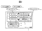
図2は、ストレージ装置2の構成を示す図である。
FIG. 2 is a diagram showing the configuration of the
ストレージ装置2は、データの記憶装置であるドライブ4と、コマンドに応じた処理を実行するストレージコントローラ5とを有する。ドライブ4は、不揮発性の記憶デバイスである。ドライブ4は、例えば、磁気ディスクやSSD(Solid State Drive)といった半導体メモリ装置であっても良い。ドライブ4とストレージコントローラ5は、それぞれ1または2以上あっても良い。
The
ストレージコントローラ5は、サーバI/F(インターフェイス)6、ドライブI/F7、装置間結合I/F40、プロセッサ8、メモリ9を有し、これらは内部ネットワークによって相互に接続される。サーバI/F6は、ネットワーク3を介してホスト計算機1と接続し、ホスト計算機1に対してコマンドやデータの送受信処理を実行する。ドライブI/F7は、ドライブ4に対してコマンドやデータの送受信処理を実行する。装置間結合I/F40は、ネットワーク41を介して他のストレージ装置2と接続し、他のストレージ装置2に対してコマンドやデータの送受信処理を実行する。一つのストレージコントローラ5内にメモリ9は、1または2以上あっても良い。ネットワーク3とネットワーク41は、それぞれに接続された装置(ホスト計算機1やストレージ装置2)間でコマンドやデータをやり取りするための通信路であり、例えば、SAN(Storage Area Network)である。
The
ネットワーク3とネットワーク41は、同じネットワークであっても良いし、互いに独立したネットワークであっても良い。なお、ネットワーク3とネットワーク41とが互いに独立したネットワークである場合、複数のストレージ装置2間でネットワーク41を介して行われる通信が、ホスト計算機1とストレージ装置2との間でネットワーク3を介して行われる通信に、影響を及ぼさない利点がある。
The
プロセッサ8は、メモリ9内のプログラムを実行して、コマンドに応じた各種の処理を実行する。プロセッサ8は、プログラムを実行する演算部または制御部であれば良い。以降では、プロセッサ8がメモリ9上のプログラムを実行して行われる処理を、ストレージ装置2やストレージコントローラ5を処理の主体として記載することがある。
The
メモリ9は、揮発性の記憶装置である。メモリ9は、データを記憶する記憶部であれば良い。複数のストレージ装置2は結合し、互いにメモリ9を共有する。複数のストレージ装置2の間で共有されるメモリ9は、複数のストレージ装置2の間で一意な識別子である論理メモリIDと、当該メモリ9が存在するストレージ装置2内で一意な識別子である物理メモリIDが付与される。
The
論理ボリューム10は、ストレージコントローラ5によって、複数のドライブ4の物理的な記憶領域から構成される。この構成方法には、例えば、RAID(Redundant Arrays of Inexpensive Disks)があり、複数のドライブ4を用いることで、データ冗長化による信頼性向上やドライブ4の並列動作による性能向上が期待できる。ストレージコントローラ5は、論理ボリューム10をホスト計算機1に提供する。ストレージ装置2は、1または2以上の論理ボリューム10を有する。
The
ホスト計算機1は、プロセッサとメモリとを有する物理計算機、または物理計算機上で稼働する仮想計算機であって良い。ホスト計算機1は、サーバとも呼ばれる。ホスト計算機1は、例えばオンライン通販サービスを提供するワークステーションである。ホスト計算機1は、ホスト計算機1が提供するサービスに必要なデータの少なくとも一部を、ストレージ装置2に格納する。ホスト計算機1は、ストレージ装置2に対して、データアクセス要求を送信することで、ストレージ装置2に格納されたデータを読み書きする。データアクセス要求として、例えば、SCSI(Small Computer System Interface)規格のリードコマンド(Read command)やライトコマンド(Write command)が用いられる。データアクセス要求は、I/O(Input/output)要求とも呼ばれる。
The
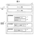
図3は、メモリ9の構成を示す図である。プロセッサ8は、後述する管理情報配置テーブル13及びキャッシュ管理テーブル18を用いて、メモリ9の記憶領域を、管理情報格納領域11とキャッシュ領域12に分けて管理する。
FIG. 3 is a diagram showing the configuration of the
管理情報格納領域11には、管理情報が格納される。管理情報には、統合管理情報と、共有管理情報と、個別管理情報がある。管理情報は、その管理情報の内容によっては、構成情報や制御情報とも呼ばれる。
Management information is stored in the management
統合管理情報は、ストレージシステムを構成する複数のストレージ装置2が其々有する情報である。統合管理情報の例として、管理情報配置テーブル13と、論物変換テーブル35と、がある。
The integrated management information is information that each of the plurality of
共有管理情報は、自ストレージ装置2だけでなく、他ストレージ装置2から参照可能な管理情報である。以下では、共有管理情報は、ストレージシステムを構成する複数のストレージ装置2のうち、一部の異なるストレージ装置2の間において冗長化される管理情報として、主に説明する。ただし、共有管理情報によっては、同じストレージ装置2内の異なるメモリ9間で、冗長化されていても良い。
The shared management information is management information that can be referred to not only from the
共有管理情報の位置(アドレス)は、統合管理情報である管理情報配置テーブル13によって管理される。このため、あるストレージ装置2内のメモリ9に格納された共有管理情報は、他のストレージ装置2と共有できる。共有管理情報は、複数のストレージ装置2のいずれかのプロセッサで実行されるプログラムと、いずれかのプログラムの実行に用いられる管理情報と、の少なくともいずれか一方を含む。プロセッサ8が実行するべきプログラムの例として、データのバックアップ機能を実現するバックアップ機能プログラムがある。プログラムの実行に用いられる管理情報の例として、バックアップ機能プログラムの実行に用いられるバックアップ機能制御情報、論理ボリューム管理テーブル26、またセキュリティ設定情報、課金情報等がある。
The position (address) of the shared management information is managed by the management information arrangement table 13 that is integrated management information. Therefore, the share management information stored in the
個別管理情報は、各ストレージ装置2で個別に管理する管理情報である。個別管理情報の例として、当該ストレージ装置2のキャッシュ領域12のアクセス頻度の情報を含むキャッシュ管理テーブル18がある。個別管理情報の内容は、異なるストレージ装置2の間では異なっていて良い。例えば、各ストレージ装置2のキャッシュ管理テーブル18は、自身のストレージ装置2のキャッシュ領域12のアクセス頻度を管理する管理情報であるので、異なるストレージ装置2間のキャッシュ管理テーブル18はその内容が異なる。また、キャッシュ管理テーブル18は、ホスト計算機1のデータアクセス要求によって、その内容が適宜変更される情報である。異なるストレージ装置2間でキャッシュ管理テーブル18を冗長化すると、その内容が変更される度に同期が必要となるので、ストレージシステムの負荷が向上し、またアクセス応答性能が劣化する可能性がある。キャッシュ管理テーブル18は、通常、当該ストレージ装置2内で使用される情報であるので、異なるストレージ装置2の間で冗長化しなくても良い。
The individual management information is management information managed individually by each
このように管理情報の用途や内容によって、アクセスするストレージ装置2が異なる。複数のストレージ装置2からアクセスされる管理情報はストレージ装置2間での冗長化が必要であり、コピー対象管理情報をこれらの管理情報に限定することで、コピーする管理情報の量を削減しても良い。例えば、コピー対象管理情報を共有管理情報に限定しても良い。
As described above, the
また、キャッシュ領域12には、ホスト計算機1からのデータアクセス要求に基づく入出力データが一時的に格納される。キャッシュ領域12に格納されるデータを、キャッシュ情報と呼ぶ。キャッシュ情報として、ライトデータやリードデータがある。キャッシュ情報は、メモリ9よりも低性能(低速)なドライブ4内のデータへのアクセスを、高性能化(高速化)するための情報である。すなわち、各ストレージ装置2のキャッシュ情報は、ストレージ装置2に接続するホスト計算機1からのライト要求に基づくライトデータと、ホスト計算機1からのリード要求への応答に用いるリードデータと、の少なくともいずれか一方を含む。
In the
例えば、ストレージ装置2がホスト計算機1からライト要求を受信すると、ストレージ装置2はライト要求にかかるライトデータをメモリ9に一旦格納し、ホスト計算機1にライト完了の応答を返す。ストレージ装置2は、メモリ9から低性能なドライブ4へのライトデータのライト処理(以後、デステージ処理とも言う。)を非同期に実行できるので、ホスト計算機1のライト要求に対して、短時間でライト完了の応答ができる。
For example, when the
また、例えば、ストレージ装置2がホスト計算機1からリード要求を受信したときリード要求にかかるデータがメモリ9に格納されている場合、ストレージ装置2はメモリ9から当該データを取得して、ホスト計算機1に応答する。リード要求にかかるデータがメモリ9に格納されていない場合、ストレージ装置2は、ドライブ4から当該データを取得してメモリ9に格納し、ホスト計算機1に応答する。リード要求にかかるデータをリードデータと呼ぶ。ストレージ装置2は、メモリ9のキャッシュ領域12にリードデータが格納されている場合、メモリ9より低性能なドライブ4からリードデータを読み出さなくても良く、ホスト計算機1のリード要求に対して短時間で応答できる。
Further, for example, when the
各ストレージ装置2は、メモリ9に障害が発生した場合等に個別管理情報やキャッシュ情報の消失を防ぐため、同じストレージ装置2の異なるメモリ9間で個別管理情報及びキャッシュ情報をコピーして多重化し、冗長性を持たせる。ただし、リードデータについては、メモリ9のキャッシュに格納されたリードデータが消失しても、ドライブ4からリードデータを読み出してホスト計算機1へ応答できるため、複数のメモリ9間で多重化しなくても良い。ライトデータについては、後述の通りに冗長化を継続または回復しても良いし、デステージ処理を実行することで、冗長化不要としても良い。また、ストレージ装置2が、メモリ9を有するストレージコントローラ5を複数備える場合、個別管理情報やキャッシュ情報を、当該ストレージ装置2内の異なるストレージコントローラ5のメモリ9に格納することで冗長化しても良い。
Each
また、各ストレージ装置2は、メモリ9に障害が発生した場合等、メモリ9の使用を停止するとき、使用を停止するメモリ9が格納する管理情報を、同じストレージ装置2内の別のメモリ9にコピーすることで、冗長性を回復しても良い。この場合の管理情報(コピー対象管理情報)には、個別管理情報、共有管理情報、統合管理情報の少なくともいずれかが含まれていて良い。
Further, when each
このとき、当該ストレージ装置2は、自ストレージ装置2が有する複数のメモリ9を対象として、アクセス性能の低下量予測処理(図10)によって、削除するキャッシュ情報を決定する。これにより、キャッシュ領域12を解放したときにおける当該ストレージ装置2のアクセス頻度への影響を小さくできる。そして、当該ストレージ装置2は、コピー対象管理情報を格納するために、解放するキャッシュ領域12が連続した領域となるように、アクセス頻度に基づいて、キャッシュ情報の再配置処理(S101、図11)を実行する。このとき、解放するキャッシュ領域12を選択する際、所定のポリシや優先度に基づいて選択されても良い。例えば、当該ストレージ装置2内の異なるストレージコントローラ5間のメモリ9で管理情報を冗長化するポリシや、当該ストレージ装置2内の異なるメモリ9の間で管理情報を冗長化するポリシ等によって、解放するキャッシュ領域12を有するメモリ9が適切に選択されて良い。当該ストレージ装置2は、当該ストレージ装置2のメモリ9のキャッシュ領域12の少なくとも一部を解放することで、コピー対象管理情報を格納するための空き容量を確保する。当該ストレージ装置2は、コピー対象管理情報を有するメモリ9から、コピー対象管理情報をコピーして、解放したキャッシュ領域12に格納することで、冗長性を回復する。
At this time, the
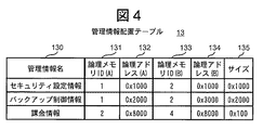
図4は、管理情報配置テーブル13の構成を示す図である。ストレージ装置2は、管理情報配置テーブル13を用いて、共有管理情報が格納されるメモリ9の管理情報格納領域11を管理する。管理情報配置テーブル13は、管理情報名130と、論理メモリID(A)131と、論理アドレス(A)132と、論理メモリID(B)133と、論理アドレス(B)134と、サイズ135と、を対応づける管理情報である。格納情報名130で識別される管理情報を格納するメモリ9の記憶領域として、論理メモリID(A)131で識別されるメモリ9の論理アドレス(A)132からサイズ135分の領域と、論理メモリID(B)133で識別されるメモリ9の論理アドレス(A)134からサイズ135分の領域とが確保されていることを示す。
FIG. 4 is a diagram showing the configuration of the management information arrangement table 13. The
例えば、図4に示す一例によると、管理情報名130が「セキュリティ設定情報」のエントリでは、「セキュリティ設定情報」と呼ばれる管理情報の格納先の記憶領域として、論理メモリID 1の論理アドレス0x1000と、論理メモリID 2の論理アドレス0x1000のそれぞれから、0x1000のサイズの記憶領域が確保されている。
For example, according to the example shown in FIG. 4, in the entry whose
各管理情報について、格納先のメモリ9のうち一方が使用不能となっても、管理情報が消失しないように、物理的なメモリ9が異なるように、論理メモリID(A)131と論理メモリID(B)133には異なるIDが設定される。
For each management information, the logical memory ID (A) 131 and the logical memory ID are different so that the
なお、本実施例では、前述のように、論理ボリューム管理テーブル26が共有管理情報であるので、この管理情報配置テーブル13で管理されるが、図4には図示していない。各ストレージ装置2で、それぞれ自ストレージ装置2の論理ボリューム10を対象として、論理ボリューム管理テーブル26が作成される。したがって、各ストレージ装置2の論理ボリューム管理テーブル26は、それぞれ管理情報配置テーブル13で管理されて良い。
In the present embodiment, since the logical volume management table 26 is shared management information as described above, it is managed by this management information arrangement table 13 but is not shown in FIG. In each
図5は、キャッシュ管理テーブル18の構成を示す図である。ストレージ装置2のプロセッサ8は、キャッシュ管理テーブル14を用いて、キャッシュ情報を格納するメモリ9のキャッシュ領域12の状態を管理する。キャッシュ領域12は、ホスト計算機1のデータアクセスに応じて、格納されるキャッシュ情報が動的に変化する。そのため、物理メモリID181と物理メモリアドレス182が示すキャッシュ領域12の小領域を、所定のサイズごとに管理する。図5の一例では、所定サイズは「0x1000」として表されている。
FIG. 5 is a diagram showing the configuration of the cache management table 18. The
キャッシュ管理テーブル18は、エントリを識別するキャッシュID180と、物理メモリID181と、物理アドレス182と、使用中フラグ183と、使用開始時刻184と、最終アクセス時刻185と、ダーティデータフラグ186と、キャッシュヒット回数187を対応づける管理情報である。キャッシュID180は、各エントリの識別子である。物理メモリID181及び物理アドレス182は、物理メモリID181で識別されるメモリ9において、物理アドレス182から所定サイズのキャッシュ領域12が、そのエントリの対象となる記憶領域であることを示している。
The cache management table 18 includes a
使用中フラグ183は、当該エントリの対象となるキャッシュ領域12に格納されたキャッシュ情報の有無を示す。使用開始時刻184は、当該キャッシュ領域12に、現在のキャッシュ情報が格納された時刻を示す。最終アクセス時刻185は、ホスト計算機1が当該エントリのキャッシュ領域12を最後にアクセスした時刻を示す。使用開始時刻184と最終アクセス時刻185は、時分秒の形式で例示しているものの、年月日があっても良い。
The in-
ダーティデータフラグ186は、当該エントリのキャッシュ情報がダーティデータであるか否かを示す。ダーティデータフラグ186がONの場合、すなわち当該エントリのキャッシュ情報がダーティデータである場合、当該キャッシュ情報が最新のライトデータであり、ドライブ4には更新前の古いデータがあることを示す。ダーティデータフラグがOFFの場合、すなわち当該エントリのキャッシュ情報がダーティデータでない場合、当該キャッシュ情報が最新データであり、またドライブ4にも最新データがあることを示す。
The dirty data flag 186 indicates whether or not the cache information of the entry is dirty data. If the dirty data flag 186 is ON, that is, if the cache information of the entry is dirty data, it indicates that the cache information is the latest write data and the
キャッシュヒット回数187は、所定の単位時間内において、ホスト計算機1からのリード要求に対して、当該リード要求にかかるデータがキャッシュ領域12に存在した回数である。このキャッシュヒット回数187は、各ストレージ装置2が有するカウンタにより計測しても良い。所定の単位時間におけるキャッシュヒット回数187は、カウンタの回数と、カウンタの計測時間から算出しても良い。
The cache hit
本実施例では、アクセス頻度を、所定の単位時間におけるキャッシュヒット回数187として説明する。また、本実施例で、アクセス頻度が低いとは、所定の単位時間におけるキャッシュヒット回数187が小さいこととして説明する。比較対象は、他ストレージ装置2または自ストレージ装置2の他メモリ9である。ただし、アクセス頻度は、この例に限定されない。例えば、アクセス頻度を、最終アクセス時刻185としても良い。この場合、アクセス頻度が低いとは、最終アクセス時刻185が古いことである。
In this embodiment, the access frequency is described as the cache hit
図6は、論理ボリューム管理テーブル26の構成を示す図である。論理ボリューム管理テーブル26は、各論理ボリューム10を識別する論理ボリュームID260と、キャッシュ保証量261と、論理ボリュームアドレス262と、キャッシュID(A)263と、キャッシュID(B)264と、ドライブID265と、ドライブアドレス266と、を対応づける管理情報である。
FIG. 6 is a diagram showing the configuration of the logical volume management table 26. The logical volume management table 26 includes a
ストレージ装置2は、論理ボリュームID260と論理ボリュームアドレス262が示す論理ボリューム10の記憶領域を、所定のサイズごとに管理する。図6の一例では、所定サイズは「0x1000」として表されている。論理ボリュームID260は、論理ボリューム10の識別子である。キャッシュ保証量261は、当該論理ボリューム10に設定されたキャッシュ保証量を示す。論理ボリュームアドレス262は、当該論理ボリューム10におけるアドレスを示す。
The
キャッシュID(A)263と、キャッシュID(B)264とは、当該論理ボリュームアドレス262に対応するキャッシュ領域12である。キャッシュID(A)263と、キャッシュID(B)264とがいずれも設定されている場合、これらのキャッシュ領域12にライトデータがあることを示している。キャッシュID(B)263は、ライトデータの二重化先のキャッシュ領域12を示しており、リードデータの場合には、設定されない。また、キャッシュID(A)263と、キャッシュID(B)264とがいずれも設定されている場合、キャッシュ領域12にデータがないことを示す。
The cache ID (A) 263 and the cache ID (B) 264 are the
ドライブID265は、ドライブ4を識別する識別子である。ドライブアドレス266は、当該ドライブ4における物理アドレスであり、論理ボリュームID260及びアドレス262で指定されるデータが格納されるドライブ4上の物理記憶領域を示す。
The
以下、ホスト計算機1がストレージ装置2へのデータアクセスしたとき、ストレージ装置2が実行するデータアクセス処理について述べる。ストレージ装置2は、ホスト計算機1から、論理ボリューム10のIDとアドレスを指定するデータアクセス要求を受信する。ストレージ装置2は、指定された論理ボリューム10のアドレスに対応づけられたキャッシュのアドレス、ドライブ4のアドレスを特定する。具体的には、論理ボリューム管理テーブル26を参照して、データアクセス要求で指定された論理ボリュームID260と論理ボリュームアドレス262に対応づけられたキャッシュID(A)263とキャッシュID(B)264、ドライブID265とドライブアドレス266を取得する。取得したキャッシュID(A)263とキャッシュID(B)264はそれぞれ、キャッシュ管理テーブル18におけるキャッシュID180に対応する。
Hereinafter, a data access process executed by the
ここで、ホスト計算機1からのリード要求に対して、当該リード要求にかかるデータがキャッシュ領域12に存在する確率(以降、キャッシュヒット率と呼ぶ)が高いほど、リード要求に対する応答は高性能となる。ただし、キャッシュ領域12は、複数の論理ボリューム10間の共有資源であり、全てのキャッシュID180のエントリについての使用中フラグ183がON(使用中)の場合には、任意のエントリのキャッシュ情報を削除して、新しいキャッシュ情報を格納する。この結果、ある論理ボリューム10へのデータアクセスによって、他の論理ボリューム10のキャッシュヒット率が低下する場合がある。ユーザはサービス毎に異なる論理ボリューム10を使用する場合があり、サービス間での性能の干渉を抑えたい要求がある。
Here, in response to a read request from the
そこで、ストレージ装置2は、論理ボリューム10毎に使用可能なキャッシュ領域12の最低容量を保証する機能を提供する。例えば、図6のように、ユーザによって設定されるキャッシュ保証量261を、論理ボリューム10毎に記憶し、削除するキャッシュ情報を選択する際、削除後もキャッシュ保証量261を満たせるか否かを判定する。満たせる場合には当該キャッシュ情報を削除し、満たせない場合には他のキャッシュ情報を削除対象とする。
Therefore, the
図7は、論物変換テーブル35の構成を示す図である。論物変換テーブル35は、各種プログラムが認識するデータの格納先である論理メモリID350及び論理アドレス351と、これらが示すデータが実際に格納されている格納先として、ストレージ装置2を識別するストレージID352と、当該ストレージ装置2における物理メモリID353と物理アドレス354とを対応づける管理情報である。各ストレージ装置2のプロセッサ8は、論理メモリID350と論理アドレス351と、ストレージID352と物理メモリID353と物理アドレス354への変換、または逆変換を、論物変換テーブル35を用いて、適宜実行する。
FIG. 7 is a diagram showing the configuration of the logical / physical conversion table 35. The logical-physical conversion table 35 includes a
前述のS102及びS103で、コピー先ストレージ装置2が、当該コピー先ストレージ装置2のメモリ9のキャッシュ領域12の少なくとも一部を解放し、コピー対象管理情報を格納する処理について述べた。本処理について、以下具体的に説明する。コピー先ストレージ装置2は、論理ボリューム管理テーブル26において、削除対象のキャッシュ情報が格納されたキャッシュ領域12のキャッシュID(A)263とキャッシュID(B)264を「なし」に設定し、当該キャッシュ領域12の使用を停止する。さらに、コピー先ストレージ装置2は、キャッシュ管理テーブル18を参照し、削除対象のキャッシュID180について、物理メモリID181と物理アドレス182が示す領域を管理情報のコピー先として記憶して、当該エントリを削除する。
In the above-described S102 and S103, the processing in which the copy
そして、コピー先ストレージ装置2は、S11のステップで記憶した管理情報のコピー先に、管理情報をコピーする。具体的には、ストレージ装置2は、管理情報配置テーブル13を参照し、論理メモリID(A)131又は論理メモリID(B)133の値が使用不能となるメモリIDとなっているエントリを検索する。ストレージ装置2は、当該エントリのアクセス可能なメモリアドレスを使用して管理情報をリードし、S11のステップで記録した管理情報のコピー先にライトする。その後、ストレージ装置2は、コピー先のメモリIDとメモリアドレスを当該エントリの使用不能となる論理メモリIDと論理メモリアドレスに上書きする。
Then, the copy
以降、ストレージ装置2の減設処理(図8)及び障害処理(図9)について述べる。これらの処理の主体となるストレージ装置2は、ストレージシステムのいずれのストレージ装置2でも良い。ただし、障害が発生したストレージ装置2以外のストレージ装置2で行われるのが望ましい。例えば、減設するストレージ装置2または障害が発生したストレージ装置2が有する管理情報のコピーを有しているストレージ装置2でこれらの処理を実行しても良い。また、各ストレージ装置2と接続し、ストレージシステムを管理する管理計算機がある場合、管理計算機が各ストレージ装置2と連携して、これらの処理を実行しても良い。
Hereinafter, the reduction process (FIG. 8) and the failure process (FIG. 9) of the
また、減設処理または障害処理を開始する契機は、これらの処理を実行するストレージ装置2が、減設するストレージ装置2または障害が発生したストレージ装置2から、減設通知または障害通知を受領した時や、ユーザの管理端末から減設処理または障害処理の実行を指示された時であっても良い。また、各ストレージ装置2間で通信時にあるストレージ装置2が、他のストレージ装置2の障害を検出したときに、障害処理を実行しても良い。
In addition, when the reduction process or the failure process is started, the
図8は、ストレージ装置2の減設処理を示すフローチャートである。複数のストレージ装置2のうち、1以上のストレージ装置2を減設する場合の処理について述べる。
FIG. 8 is a flowchart showing the reduction process of the
ストレージ装置2は、各ストレージ装置2における管理情報の容量(以後、管理情報量という。)とキャッシュ保証量の合計、また減設後のメモリ量の合計(以後、減少後のメモリ量という。)を算出する。ストレージ装置2は、減少後のメモリ量が、管理情報量とキャッシュ保証量の合計(以後、必要なメモリ量という。)を上回るか否かを判定する(S1)。ここで、必要なメモリ量と減少後のメモリ量について、ストレージ装置2は、各ストレージ装置2の管理情報配置テーブル13とキャッシュ管理テーブル18と論理ボリューム管理テーブル26とに基づいて算出しても良い。または、ストレージ装置2は、各ストレージ装置2に対して、メモリ量と管理情報量とキャッシュ保証量を返却するように要求し、各ストレージ装置2から返却されたメモリ量、管理情報量とキャッシュ保証量に基づいて、必要なメモリ量と減少後のメモリ量を算出しても良い。
The
減少後のメモリ量が必要なメモリ量を上回る場合、減設対象のストレージ装置2のメモリ9に格納された管理情報を、他のストレージ装置2のメモリ9に退避する退避処理を実行する(S2)。この管理情報の退避処理(S2)は、図1を用いて前述したとおりである。その後、ユーザの管理端末に対して、ストレージ装置2の減設が可能であることを示す情報を表示しても良い(S3)。ユーザは、その表示内容を確認した上で、ストレージ装置2を減設可能となる。
When the memory amount after the reduction exceeds the required memory amount, a save process is executed to save the management information stored in the
S1の判定で、減少後のメモリ量が必要なメモリ量を上回らない場合、減設すると必要な情報を残りのストレージ装置2のメモリ9に格納できないために減設できない旨を、ユーザの管理端末に表示しても良い(S4)。このとき、ストレージ装置2は、例えば、ユーザに対して減設後にどの程度メモリ量が不足するかを示す情報を表示しても良い。ユーザは、その表示内容を参照することで、キャッシュ保証量28の見直しなどを実行して必要なメモリ量を減少させたうえで、ストレージ装置2に再び減設処理を実行させることができる。
If it is determined in S1 that the amount of memory after the decrease does not exceed the required amount of memory, the user management terminal indicates that if it is reduced, the necessary information cannot be stored in the
図9は、ストレージ装置2の障害処理を示すフローチャートである。複数のストレージ装置2のうち、1以上のストレージ装置2で障害が発生した場合の処理について述べる。
FIG. 9 is a flowchart showing failure processing of the
ストレージ装置2は、他ストレージ装置2における障害を検出すると、図8のS1のステップと同じ処理を実行する。S1の判定で、必要なメモリ量を上回る場合、S2の管理情報の退避処理を実行する。
When the
S1の判定で、必要なメモリ量を上回らない場合、障害時のポリシを参照する(S5)。障害時のポリシとは、管理情報の二重化とキャッシュ保証量の両立ができない場合に信頼性と性能のどちらを優先するかを定めた情報であり、ユーザによって設定される。 If the required amount of memory is not exceeded in the determination of S1, the policy at the time of failure is referred to (S5). The policy at the time of failure is information that determines whether to give priority to reliability or performance when duplication of management information and cache guarantee amount cannot be achieved, and is set by the user.
性能優先のポリシの場合(S5 No)、管理情報を一重状態のままとし、信頼性を回復させない(S8)。このステップS8では、例えば、ストレージ装置2は、ユーザの管理端末に対して、メモリ量の不足によって信頼性を回復できない旨を表示しても良い。また、ストレージ装置2は、キャッシュ保証量の見直しや、早期に障害部品の交換作業を促す情報を、ユーザの管理端末に表示しても良い。
In the case of a performance priority policy (S5 No), the management information remains in a single state, and the reliability is not recovered (S8). In this step S8, for example, the
S5において信頼性優先のポリシであった場合(S5 Yes)、キャッシュ保証量のうち、実際に使用しているキャッシュ量のみを必要なメモリ量と見なして、必要なメモリ量を再計算する(S6)。具体的には、論理ボリューム管理テーブル26の論理ボリュームID260ごとに、キャッシュID(A)263とキャッシュID(B)264の有無を集計し、使用中のキャッシュ量を算出する。算出した使用中のキャッシュ量とキャッシュ保証量261を比較し、小さい値を当該論理ボリューム10で保証すべきメモリ量とする。管理情報配置テーブル13のサイズ135の2倍と、論理ボリューム10ごとの保証すべきメモリ量との合計を必要なメモリ量とし、減少後のメモリ量と比較する。
If the priority policy is the reliability priority in S5 (S5 Yes), only the cache amount actually used in the cache guarantee amount is regarded as the necessary memory amount, and the necessary memory amount is recalculated (S6). ). Specifically, for each
減少後のメモリ量が再計算した必要なメモリ量を上回る場合(S6 Yes)、S2の管理情報の退避処理を実行する。減少後のメモリ量が再計算した必要なメモリ量を上回らない場合(S6 No)、S8のステップを実行する。 When the memory amount after the decrease exceeds the recalculated necessary memory amount (S6 Yes), the management information saving process in S2 is executed. When the memory amount after the decrease does not exceed the recalculated necessary memory amount (No in S6), the step of S8 is executed.
これにより、サービスの性能よりもサービスの信頼性を優先するユーザの要求を満たせる。また、ホスト計算機1のデータアクセスパタンが変わらない限り、使用するキャッシュ量は増加しないため、性能を低下させることなく、信頼性を維持できる。
As a result, it is possible to satisfy a user's request that prioritizes service reliability over service performance. Further, as long as the data access pattern of the
S2のステップ実行後、管理情報の信頼性回復を完了する(S7)。S7のステップでは、例えば、ストレージ装置2は、障害の発生と信頼性が回復されたことを示す情報を、ユーザの管理端末に表示しても良い。また、ストレージ装置2は、障害の発生していないストレージ装置2をそのまま動作させても良いことを、ユーザの管理端末に表示しても良い。また、ストレージ装置2は、ユーザの管理端末に、障害部品の交換作業を促す情報を表示しても良い。
After the step S2 is executed, the management information reliability recovery is completed (S7). In the step of S7, for example, the
図10は、アクセス性能の低下量予測処理のフローチャートである。以下、アクセス性能の低下量が、キャッシュヒット率の低下量であるときの例を述べる。本処理は、コピー先候補ストレージ装置の其々で実行する。そのため、コピー先候補ストレージ装置の其々のメモリ9のキャッシュ領域12の使用状態に基づいて、キャッシュヒット率の低下を抑えるように、コピー先ストレージ装置及び解放するキャッシュ領域12を決定することができる。
FIG. 10 is a flowchart of the access performance decrease amount prediction process. Hereinafter, an example in which the amount of decrease in access performance is the amount of decrease in the cache hit rate will be described. This process is executed in each copy destination candidate storage device. Therefore, the copy destination storage apparatus and the
まず、コピー先候補ストレージ装置2は、コピー対象管理情報の容量を取得する(S14)。図1の例で説明したように、ストレージ装置Aが、コピー先候補ストレージ装置C、Dの其々に、コピー対象管理情報(共有管理情報X)の容量を通知することにより実行されても良い。または、コピー先候補ストレージ装置が、管理情報配置テーブル13を参照して、論理メモリID(A)131又は論理メモリID(B)133の値が使用不能となるメモリIDとなっているエントリを検索する。当該エントリのサイズ135の合計値を、コピー対象管理情報の容量としても良い。コピー対象管理情報の容量を、この時点での「削除するキャッシュ情報量」とする。
First, the copy destination
次に、コピー先候補ストレージ装置2は、個別管理情報であるキャッシュ管理テーブル18を用いて、自身が有する全メモリ9のキャッシュ領域12を使用頻度の低い順序に並び替える(S15)。これは、キャッシュヒット率を低下させにくい順にキャッシュ情報を並び替えることを目的としており、例えば、キャッシュ管理テーブル18の最終アクセス時刻185の順に並び替える。他にも、最終アクセス時刻185が同じ場合には、使用開始時刻184の古い方を優先して並び替える方法、キャッシュヒット回数187の少ない方を優先して並び替える方法、などがあり、過去のキャッシュの使用状況を使用する限り、その方法はS15のステップに記載に限定されない。
Next, the copy destination
コピー先候補ストレージ装置2は、S15のステップで並び替えた使用頻度の低い順にキャッシュ領域12を特定し(S16)、当該キャッシュ領域12を確保する必要があるか否かを判定する(S17)。具体的には、コピー先候補ストレージ装置2は、キャッシュ管理テーブル18を参照して、取り出したキャッシュ領域12に合致するエントリを特定し、当該エントリID180を持つ論理ボリューム管理テーブル26のエントリを特定する。コピー先候補ストレージ装置2は、特定したエントリにおいて、キャッシュID(A)263とキャッシュID(B)264が示すキャッシュ領域12の割り当て量とキャッシュ保証量261を比較する。コピー先候補ストレージ装置2は、当該キャッシュ領域12を解放しても、論理ボリューム10のキャッシュ領域12の割り当て量がキャッシュ保証量261を下回らない場合(S17 No)、保証不要と判定してS18のステップを実行する。一方、論理ボリューム10のキャッシュ領域12の割り当て量がキャッシュ保証量261を下回る場合(S17 Yes)、コピー先候補ストレージ装置2は、保証要と判断してS16のステップを実行する。
The copy destination
コピー先候補ストレージ装置2は、S17のステップで確保不要と判定した後、当該キャッシュ領域12を削除対象に設定(S18)し、「削除するキャッシュ情報量」から当該キャッシュ領域12のサイズを減算して、更新する(S19)。更新した「削除するキャッシュ情報量」が0より大きい場合、さらにキャッシュ情報を削除する必要があると判定してS16のステップを実行する(S20 Yes)。
The copy destination
更新した「削除するキャッシュ情報量」が0以下の場合、(S20 No)、コピー先候補ストレージ装置2は、キャッシュ管理テーブル18を参照して、削除対象キャッシュ領域12における所定の単位時間あたりのキャッシュヒット回数187の合計を、当該ストレージ装置が所定の単位時間あたりに受信したリード回数、すなわちリード要求の数で割ることで、アクセス性能の低下量の予測値を算出する(S200)。ただし、アクセス性能の低下量の予測値は、他の方法で算出しても良く、S200の記載に限定されない。
When the updated “amount of cache information to be deleted” is 0 or less (No in S20), the copy destination
図11は、キャッシュ情報の再配置処理のフローチャートである。本処理は、コピー先ストレージ装置で実行する。本処理により、コピー対象管理情報を格納するために必要な連続したメモリ領域を確保し、またキャッシュ領域12の解放後のアクセス性能の低下を抑えることができる。
FIG. 11 is a flowchart of the cache information rearrangement process. This process is executed in the copy destination storage apparatus. With this processing, it is possible to secure a continuous memory area necessary for storing the copy target management information, and to suppress a decrease in access performance after the
以下の説明では、簡単化のために削除対象のキャッシュ領域12を一か所に再配置する処理を説明するものの、一か所に限定されるものではない。また、コピー対象管理情報を複数のメモリ領域に分けて管理できるならば、複数のメモリ領域に再配置しても良いし、コピー対象管理情報をキャッシュ領域12の連続したメモリ領域に配置できるならば再配置そのものを実行しなくても良い。ただし、複数のメモリ領域に細かく分けてコピー対象管理情報を管理するほど、細分化された管理情報の格納先メモリを記憶するためのメモリ消費量が増大する。例えば、管理情報配置テーブル13のエントリが増加する。このため、ある程度の大きな連続領域で管理情報を格納することで、メモリ9の使用効率を向上できる。
In the following description, the process of rearranging the
まず、コピー先ストレージ装置2は、使用可能なメモリ9を選択(S21)し、削除対象のキャッシュ領域12を列挙する(S22)。
First, the copy
次に、コピー先ストレージ装置2は、削除対象のキャッシュ領域12の密度が高い領域を再配置先のキャッシュ領域12に設定する(S23)。これは、再配置するキャッシュ情報の数を少なくすることを目的としている。
Next, the copy
コピー先ストレージ装置2は、列挙したキャッシュ領域12の先頭を取り出し(S24)、再配置先のメモリ領域外にあるか否かを判定する(S25)。コピー先ストレージ装置2は、再配置先のメモリ領域外にある場合(S25 Yes)、削除対象でなくかつ領域内にあるキャッシュ情報と取り出したキャッシュ情報とのデータを交換する(S26)。具体的には、コピー先ストレージ装置2は、キャッシュ管理テーブル18のエントリ間で物理アドレス182が示す領域のキャッシュ情報を相互に移動した上で、エントリ間で物理アドレス182、使用開始時刻184、最終アクセス時刻185、ダーティデータフラグ186、アクセスヒット回数187も相互に移動する。なお、この処理はキャッシュ情報の配置変更であり、キャッシュ領域12へのデータアクセスではないため、使用開始時刻184や最終アクセス時刻185は変更しない。
The copy
コピー先ストレージ装置2は、S25のステップにて再配置先のメモリ領域内と判定された場合(S25 No)、又はS26のステップを実行した場合、キャッシュ管理テーブル18を参照して、S24のステップで取り出したキャッシュ領域12に対応するエントリのダーティデータフラグ186を参照する(S27)。
The copy
コピー先ストレージ装置2は、ダーティデータフラグ186がONの場合(S27 Yes)、ドライブ4のデータは旧データであり、当該キャッシュ領域12のキャッシュ情報が最新データであるため、キャッシュ情報を削除する前に、キャッシュ情報をドライブ4に格納する(S28)。具体的には、コピー先ストレージ装置2は、論理ボリューム管理テーブル26を参照して、キャッシュID(A)263と(B)264の値が当該キャッシュのID180と合致するエントリを特定する。特定したエントリのドライブID265とドライブアドレス266が示す領域に、当該キャッシュ情報を格納する。その後、ダーティデータフラグ186をOFFに設定する。これにより、当該キャッシュ領域12のキャッシュ情報を削除できる。
When the dirty data flag 186 is ON (S27 Yes), the copy
コピー先ストレージ装置2は、ダーティデータフラグ186がOFFの場合(S27 No)、ドライブ4のデータに最新データであるため、当該キャッシュ領域12のキャッシュ情報を削除できる。
When the dirty data flag 186 is OFF (No at S27), the copy
そして、列挙したキャッシュ領域12の残りがあるか否かを確認する(S29)。残りがあれば(S29 Yes)、S24のステップを実行する。残りがなければ(S29 No)、処理を終了する。
Then, it is confirmed whether or not there is a remaining
なお、本実施例では、キャッシュ情報の再配置処理において、再配置先のメモリ領域内外のキャッシュ情報の交換(S26)、ドライブへの最新データとなるキャッシュ情報の格納(S28)、キャッシュ情報の削除(S102)の順で処理を説明した。しかし、S28のステップ、S102のステップを先に実行すると、S26のステップでは再配置先のメモリ領域内の削除対象でないキャッシュ情報を領域外の空き領域に移動すれば良く、キャッシュ情報の交換に比べて、データコピー回数を減らすことができる。削除するキャッシュ領域12をキャッシュヒット率が低下しにくいように選択し、削除した領域にコピー対象管理情報の二重化するという限り、処理の順序は記載のみに限定されるものではない。
In this embodiment, in the cache information relocation process, the cache information is exchanged inside and outside the relocation destination memory area (S26), the cache information to be the latest data is stored in the drive (S28), and the cache information is deleted. The processing has been described in the order of (S102). However, if the steps S28 and S102 are executed first, the cache information that is not to be deleted in the relocation destination memory area may be moved to a free area outside the area in the step S26. Thus, the number of data copies can be reduced. As long as the
図10で説明したアクセス性能の低下量予測処理と、図11のキャッシュ情報の再配置処理を実行することにより、コピー先ストレージ装置2は、以下の処理を実行する。コピー先ストレージ装置2のプロセッサ8は、キャッシュ管理テーブル18を用いて、当該コピー先ストレージ装置のメモリ9のキャッシュ領域12を複数の小領域に分けて、各小領域のアクセス頻度を管理する。ここで、小領域とは、キャッシュ管理テーブルのキャッシュID180の各エントリで管理されるキャッシュ領域12である。コピー先ストレージ装置2は、各小領域のアクセス頻度に基づいて、アクセス頻度の低い小領域に格納されたキャッシュ情報の使用を停止することで、キャッシュ領域12の少なくとも一部を解放する。ここで、コピー先ストレージ装置2のプロセッサ8は、論理ボリューム管理テーブル26を用いて、論理ボリューム10に設定されるキャッシュ保証量261を管理し、キャッシュ領域12のアクセス頻度の低い小領域を解放してもキャッシュ保証量を満たす場合に、当該小領域に格納されたキャッシュ情報の使用を停止する。これにより、コピー先ストレージ装置において、キャッシュ領域12を解放した後のアクセス性能の低下を抑えることができる。
The copy
また、コピー先ストレージ装置を決定する処理(S100)において、過去にメモリ障害が発生したストレージ装置2をコピー先ストレージ装置としないことで、今後の障害における管理情報の退避処理を省略できる可能性がある。例えば、サービスの成長に合わせて、ストレージ装置2を徐々に増設した場合、新旧のメモリ9が混在するストレージ装置となる。ここで、初期購入した比較的古いストレージ装置2のあるメモリ9に障害が発生した場合に、当該ストレージ装置2の別のメモリ9のキャッシュ領域12を解放して管理情報をコピーしても、当該メモリ9も故障したメモリ9と同様に比較的古いため、障害が発生する可能性が高い。このため、比較的新しい他のストレージ装置2のメモリ9のキャッシュ領域12を優先的に解放して管理情報をコピーしても良い。
Further, in the process of determining the copy destination storage device (S100), there is a possibility that the management information saving process in the future failure can be omitted by not using the
S103の管理情報のコピー処理では、前述のように、コピー先ストレージ装置は、解放したキャッシュ領域12にコピー対象管理情報を格納する。このとき、管理情報配置テーブル13の論理メモリID131と論理アドレス132を変更しても良い。しかし、ストレージ装置2で実行される各種プログラムが共有管理情報の格納先である論理メモリID131と論理アドレス132を静的に記憶している場合、又はプログラム初期起動時に管理情報配置テーブル13から過去に読み込んだ値を再利用している場合、S103のステップでコピー対象管理情報の格納先が変わると、当該コピー対象管理情報へのアクセスができなくなる。
In the management information copy process of S103, as described above, the copy destination storage apparatus stores the copy target management information in the released
そこで、本実施例では、S103のステップでコピー対象管理情報の格納先が変わった場合に、管理情報配置テーブル13の論理メモリID131と論理アドレス132を変更せず、論物変換テーブル35を更新する。具体的には、コピー先ストレージ装置2は、構成情報配置テーブル13及び論物変換テーブル35を用いて、障害が発生したストレージ装置2または減設するストレージ装置2において、コピー対象管理情報が格納されたメモリ9の論理メモリID131と論理アドレス132を特定する。コピー先ストレージ装置2は、論物変換テーブル35において、特定した論理メモリID131と論理アドレス132に対するエントリに対し、自身のストレージID352、コピー対象管理情報の格納先である自身のメモリ9の物理メモリID353及び物理アドレス354に更新する。
Therefore, in this embodiment, when the storage location of the copy target management information changes in step S103, the logical-physical conversion table 35 is updated without changing the
また、論物変換テーブル35は、全てのストレージ装置2がそれぞれ有する統合管理情報であるため、各ストレージ装置2の論物変換テーブル35を更新する。例えば、コピー先ストレージ装置2は、コピー対象管理情報の格納先(ストレージID352、物理メモリID353、物理アドレス354)を、複数のストレージ装置2の少なくとも一部または全部に通知することで、各ストレージ装置2の論物変換テーブル35を更新する。例えば、通知先のストレージ装置2は、使用を停止するストレージ装置2と当該通知先のストレージ装置2自身以外のストレージ装置2に、コピー対象管理情報の格納先を通知する。通知されたストレージ装置2は、其々論物変換テーブル35を更新する。
Further, since the logical / physical conversion table 35 is the integrated management information of all the
図12は、論物変換テーブル35を用いた共有管理情報へのアクセス処理を示すフローチャートである。本処理は、各ストレージ装置2で実行される。例えば、ストレージ装置2のプロセッサ8で実行されるプログラムが論理メモリIDと論理アドレスを指定して共有管理情報にアクセスしようとすると、以下に示す共有管理情報へのアクセス処理を実施する。
FIG. 12 is a flowchart showing access processing to shared management information using the logical / physical conversion table 35. This process is executed in each
まず、ストレージ装置2は、論物変換テーブル35を参照して、指定された論理メモリIDと論理アドレスに合致するエントリを、管理情報配置テーブル13から検索する(S30)。ストレージ装置2は、合致するエントリがあれば(S30 Yes)、指定された論理メモリID131と論理アドレス132は管理情報格納領域と判定してS31のステップを実施する。ストレージ装置2は、合致するエントリがなければ(S30 No)、管理情報格納領域でないと判定してデータアクセス失敗とする(S34)。
First, the
S31のステップでは、ストレージ装置2は、論物変換テーブル35を参照して、指定された論理メモリIDと論理アドレスに合致する論理メモリID350と論理アドレス351を持つエントリを検索する。
In step S31, the
次に、ストレージ装置2は、S31のステップで検索したエントリにおけるストレージID352と、物理メモリID353と物理アドレス354が示すメモリ領域のデータにアクセスし(S32)、データアクセス成功とする(S33)。
Next, the
以上のように、論物変換テーブル35を設けることで、ストレージ装置2のプロセッサ8で実行されるプログラムは、S103により共有管理情報の格納場所が変更されても、同じ論理メモリID131と論理アドレス132を使って管理情報にアクセスできる。
As described above, by providing the logical-physical conversion table 35, the program executed by the
これまで、ストレージ装置2の減設や障害によって、使用可能なメモリ9が減少する場合に、管理情報の二重化を継続する方法を述べた。ここで、ストレージ装置2の増設や、障害回復によって使用可能なメモリ9が増加する場合には、ストレージ装置2は増加したメモリ9にキャッシュ情報を格納することで性能向上を図る。ただし、メモリ障害時処理のS8のステップを実施して管理情報が二重化されていない状態であれば、増加したメモリ9を管理情報の退避先に選択し、S103のステップにより管理情報を二重化して信頼性を回復しても良い。
Up to now, a method has been described in which duplication of management information is continued when the
また、ストレージシステムの管理情報配置テーブル13及び論物変換テーブル35の通常時(ストレージ装置障害発生前または減設前等)の状態を記憶しておき、ストレージ装置障害発生後または減設後に、ストレージシステムに1以上のストレージ装置2を増設するとき、通常時の状態に復旧しても良い。例えば、ストレージシステムに1以上のストレージ装置2を増設するとき、増設するストレージ装置2が有するメモリ9に、前記統合管理情報と、コピー対象管理情報を格納し、コピー先ストレージ装置2が有するメモリ9のうち、コピー対象管理情報が格納された領域を解放し、前記キャッシュ情報を格納しても良い。
Further, the storage system management information arrangement table 13 and the logical-physical conversion table 35 are stored in a normal state (before a storage device failure or before removal), and after storage device failure or after removal, the storage When one or
以上の説明では、ストレージシステムが有する各情報について、テーブルなどの表現で説明する場合があるが、各情報のデータ構造は限定されず、他のデータ構造であってもよい。各情報はデータ構造に依存しないため、例えば、「kkkテーブル」を「kkk情報」と呼ぶことができる。 In the above description, each piece of information included in the storage system may be described in terms of a table or the like. However, the data structure of each piece of information is not limited, and other data structures may be used. Since each information does not depend on the data structure, for example, “kkk table” can be called “kkk information”.
また、以上の説明において、プロセッサ8は、プログラムを実行し、記憶資源(例えば、メモリ9)及び/又は通信インターフェイスデバイス(例えば、通信ポート)等を用いながら処理を行う。プロセッサ8を主体とする処理は、1以上のプログラムを実行する事によりおこなわれると解釈されてもよい。また、ストレージ装置2を主体とする処理は、当該ストレージ装置2のプロセッサ8を主体として実行されると解釈されてもよい。プロセッサ8は、典型的には、CPU(Central Processing Unit)のようなマイクロプロセッサであるが、処理の一部(例えば、暗号化/復号化、圧縮/伸張)を実行するハードウェア回路を含んでもよい。
In the above description, the
1 ホスト計算機、2 ストレージ装置、3 ネットワーク、4 ドライブ、5 ストレージコントローラ、6 サーバI/F、7 ドライブI/F、8 プロセッサ、9 メモリ、10 論理ボリューム、11 管理情報格納領域、12 キャッシュ領域、40 装置間結合I/F、41 ネットワーク 1 host computer, 2 storage device, 3 network, 4 drive, 5 storage controller, 6 server I / F, 7 drive I / F, 8 processor, 9 memory, 10 logical volume, 11 management information storage area, 12 cache area, 40 Inter-device connection I / F, 41 network
Claims (15)
前記複数のストレージ装置の其々は、管理情報を格納する管理情報格納領域とキャッシュ情報を格納するキャッシュ領域とを有するメモリと、前記キャッシュ領域の状態を管理するプロセッサと、を備え、
前記第1ストレージ装置のメモリの使用を停止するとき、前記複数のストレージ装置の少なくとも一部のプロセッサは、前記第1ストレージ装置以外の前記ストレージ装置が其々管理する前記キャッシュ領域の状態に基づいて、前記使用を停止するメモリが格納する管理情報であるコピー対象管理情報のコピー先となるコピー先ストレージ装置を決定し、
前記コピー先ストレージ装置のプロセッサは、前記コピー先ストレージ装置のメモリのキャッシュ領域の少なくとも一部を解放して、前記解放したキャッシュ領域に、前記コピー対象管理情報を格納する
ことを特徴とするストレージシステム。 A storage system comprising a plurality of storage devices including a first storage device,
Each of the plurality of storage devices comprises a memory having a management information storage area for storing management information and a cache area for storing cache information, and a processor for managing the state of the cache area,
When the use of the memory of the first storage device is stopped, at least some of the processors of the plurality of storage devices are based on the state of the cache area managed by the storage devices other than the first storage device. Determining a copy destination storage device as a copy destination of copy target management information which is management information stored in the memory to be stopped from use,
The processor of the copy destination storage apparatus releases at least a part of the cache area of the memory of the copy destination storage apparatus, and stores the copy target management information in the released cache area. .
前記キャッシュ情報は、前記複数のストレージ装置の少なくともいずれかが備える記憶デバイスに同じデータが格納されている場合、前記複数のストレージ装置のいずれのメモリからも削除可能な情報であり、
前記キャッシュ領域の状態は、前記キャッシュ領域のアクセス頻度の情報を少なくとも含み、
前記複数のストレージ装置に、前記使用を停止するメモリが格納する管理情報のコピー先の候補となるコピー先候補ストレージ装置が複数ある場合、前記少なくとも一部のプロセッサは、
前記コピー先候補ストレージ装置が其々管理する前記キャッシュ領域のアクセス頻度に基づいて、前記コピー先候補ストレージ装置の其々に前記コピー対象管理情報をコピーした場合のアクセス性能の低下量を予測し、
前記複数のコピー先候補ストレージ装置のうち、前記予測したアクセス性能の低下量の低いストレージ装置を、前記コピー先ストレージ装置に決定する
ことを特徴とする請求項1に記載のストレージシステム。 The management information is stored in at least one of the memories of the plurality of storage apparatuses when the plurality of storage apparatuses are operating, and can be referenced from the memory by at least one of the processors of the plurality of storage apparatuses. Information,
The cache information is information that can be deleted from any memory of the plurality of storage devices when the same data is stored in a storage device provided in at least one of the plurality of storage devices.
The state of the cache area includes at least information on the access frequency of the cache area,
When there are a plurality of copy destination candidate storage devices that are candidates for the copy destination of the management information stored in the memory whose use is stopped in the plurality of storage devices, the at least some processors are
Based on the access frequency of the cache area in which the copy destination candidate storage apparatus其s management, predicts the amount of reduction in access performance in the case of copying the copy object management information其s of the copy destination candidate storage unit ,
2. The storage system according to claim 1, wherein, among the plurality of copy destination candidate storage devices, the storage device having the low predicted decrease in access performance is determined as the copy destination storage device.
前記第1ストレージ装置のメモリと前記第2ストレージ装置のメモリに、前記コピー対象管理情報を其々格納することで、前記コピー対象管理情報を冗長化しており、
前記第1ストレージ装置のメモリの使用を停止するとき、前記コピー先ストレージ装置のメモリに前記コピー対象管理情報を格納することで、前記第2ストレージ装置のメモリと前記コピー先ストレージ装置のメモリで前記コピー対象管理情報を冗長化し、
前記コピー先ストレージ装置は、前記コピー対象管理情報の格納先を、前記複数のストレージ装置の少なくとも一部に通知する
ことを特徴とする請求項2に記載のストレージシステム。 The plurality of storage devices include at least the first storage device, the second storage device, and the copy destination storage device,
The copy target management information is made redundant by storing the copy target management information in the memory of the first storage device and the memory of the second storage device, respectively.
When stopping the use of the memory of the first storage device, the copy target management information is stored in the memory of the copy destination storage device, so that the memory of the second storage device and the memory of the copy destination storage device Make the copy management information redundant,
The storage system according to claim 2, wherein the copy destination storage apparatus notifies the storage destination of the copy target management information to at least a part of the plurality of storage apparatuses.
前記少なくとも2以上のコピー先候補ストレージ装置は其々、前記アクセス性能の低下量を予測して、前記第2ストレージ装置に前記予測した低下量を送信し、
前記第2ストレージ装置は、前記少なくとも2以上のコピー先候補ストレージ装置其々で予測した低下量に基づき、前記予測したアクセス性能の低下量の低いコピー先候補ストレージ装置を、前記コピー先ストレージ装置に決定し、
前記コピー先ストレージ装置は、前記第2ストレージ装置から前記コピー対象管理情報をコピーする
ことを特徴とする請求項3に記載のストレージシステム。 The copy destination candidate storage device is at least two or more storage devices other than the first storage device and the second storage device among the plurality of storage devices,
Each of the at least two or more copy destination candidate storage devices predicts the amount of decrease in the access performance, and sends the predicted amount of decrease to the second storage device,
The second storage device, based on the predicted decrease amount of each of the at least two or more copy destination candidate storage devices, converts the predicted copy destination candidate storage device with a low access performance decrease amount to the copy destination storage device. Decide
The storage system according to claim 3, wherein the copy destination storage device copies the copy target management information from the second storage device.
前記複数のストレージ装置がそれぞれ有する統合管理情報と、
他ストレージ装置から参照可能な共有管理情報と、
各ストレージ装置で個別に管理する管理情報であって、当該ストレージ装置の前記キャッシュ領域のアクセス頻度の情報を含む個別管理情報と、
を有し、
前記コピー対象管理情報は、前記第1ストレージ装置及び前記第2ストレージ装置其々のメモリに格納された前記共有管理情報である
ことを特徴とする請求項4に記載のストレージシステム。 The management information stored in the memory of each of the plurality of storage devices is
Integrated management information respectively possessed by the plurality of storage devices;
Share management information that can be referenced from other storage devices,
Management information individually managed by each storage device, including individual management information including access frequency information of the cache area of the storage device;
Have
The storage system according to claim 4, wherein the copy target management information is the shared management information stored in a memory of each of the first storage device and the second storage device.
前記各小領域のアクセス頻度に基づいて、アクセス頻度の低い小領域に格納されたキャッシュ情報の使用を停止することで、前記キャッシュ領域の少なくとも一部を解放する
ことを特徴とする請求項5に記載のストレージシステム。 The processor of the copy destination storage apparatus divides the cache area of the memory of the copy destination storage apparatus into a plurality of small areas, and manages the access frequency of each small area,
6. The cache area according to claim 5, wherein at least a part of the cache area is released by stopping the use of cache information stored in the small area with low access frequency based on the access frequency of each small area. The described storage system.
ことを特徴とする請求項6に記載のストレージシステム。 The processor of the copy destination storage apparatus relocates the cache information of the copy destination storage apparatus based on the access frequency so that the cache area for storing the copy target management information becomes a continuous area. The storage system according to claim 6.
前記コピー先ストレージ装置のプロセッサは、
前記論理ボリュームに設定されるキャッシュ保証量を管理し、
前記コピー先ストレージ装置のメモリのキャッシュ領域が有する小領域であって、当該小領域を解放しても前記キャッシュ保証量を満たす場合に、当該小領域に格納されたキャッシュ情報の使用を停止する
ことを特徴とする請求項6に記載のストレージシステム。 The copy destination storage apparatus further includes one or more storage devices that constitute a logical volume to be provided to the host computer,
The processor of the copy destination storage device is:
Manage the cache guarantee amount set for the logical volume,
If the cache area of the memory of the copy destination storage apparatus has a small area and the cache guarantee amount is satisfied even if the small area is released, the use of the cache information stored in the small area is stopped. The storage system according to claim 6.
各ストレージ装置は、当該ストレージ装置で個別に管理する前記個別管理情報を、当該ストレージ装置内の異なるメモリに格納することで冗長化する
ことを特徴とする請求項5に記載のストレージシステム。 Each of the plurality of storage devices has a plurality of memories,
The storage system according to claim 5, wherein each storage device is made redundant by storing the individual management information individually managed by the storage device in a different memory in the storage device.
各ストレージ装置は、当該ストレージ装置で個別に管理する前記個別管理情報を、当該ストレージ装置内の異なるコントローラのメモリに格納することで冗長化する
ことを特徴とする請求項9に記載のストレージシステム。 Each of the plurality of storage devices includes a plurality of controllers having a memory,
The storage system according to claim 9, wherein each storage device is made redundant by storing the individual management information individually managed by the storage device in a memory of a different controller in the storage device.
ことを特徴とする請求項5に記載のストレージシステム。 The use of the memory of the first storage device is stopped when a failure occurs in the first storage device or when the first storage device is removed. Storage system.
各ストレージ装置の前記キャッシュ情報は、当該ストレージ装置に接続するホスト計算機からのライト要求に基づくライトデータと、当該ホスト計算機からのリード要求への応答に用いるリードデータと、の少なくともいずれか一方を含む
ことを特徴とする請求項5に記載のストレージシステム。 The management information of each storage device includes at least one of a program executed by any one of the processors and information used for executing any one of the programs,
The cache information of each storage device includes at least one of write data based on a write request from a host computer connected to the storage device and read data used in response to a read request from the host computer. The storage system according to claim 5.
前記増設するストレージ装置が有するメモリに、前記統合管理情報と、前記コピー対象管理情報を格納し、
前記コピー先ストレージ装置が有するメモリのうち、前記コピー対象管理情報が格納された領域を解放し、前記キャッシュ情報を格納する
ことを特徴とする請求項5に記載のストレージシステム。 When adding one or more storage devices to the storage system,
The integrated management information and the copy target management information are stored in the memory of the additional storage device,
The storage system according to claim 5, wherein an area in which the copy target management information is stored is released from the memory of the copy destination storage apparatus, and the cache information is stored.
前記複数のストレージ装置のうちの1つのストレージ装置のメモリの使用を停止するとき、前記1つのストレージ装置以外のストレージ装置であって、当該ストレージ装置のメモリのキャッシュ領域の少なくとも一部を解放して、前記使用を停止するメモリが格納する管理情報をコピーするストレージ装置を、前記1つのストレージ装置以外のストレージ装置が其々管理する前記キャッシュ領域の状態に基づいて決定する制御部と、
を備えることを特徴とするストレージ装置。 A memory unit having a management information storage area for storing management information and a cache area for storing cache information, a processor for managing the state of the cache area, and a connection unit connected to a plurality of storage devices, respectively.
When stopping the use of the memory of one storage device among the plurality of storage devices, the storage device is a storage device other than the one storage device, and at least a part of the cache area of the memory of the storage device is released. A control unit that determines a storage device that copies management information stored in the memory to be stopped based on a state of the cache area that is managed by a storage device other than the one storage device;
A storage apparatus comprising:
前記複数のストレージ装置は、第1ストレージ装置と第2ストレージ装置を含む4以上のストレージ装置を少なくとも備え、
前記複数のストレージ装置の其々は、管理情報を格納する管理情報格納領域とキャッシュ情報を格納するキャッシュ領域とを有するメモリと、前記キャッシュ領域のアクセス頻度を管理するプロセッサと、を備え、
前記第1ストレージ装置のメモリと前記第2ストレージ装置のメモリに、同一の管理情報を其々格納することで、前記同一の管理情報を冗長化しており、
前記第1ストレージ装置のメモリの使用を停止するとき、前記第1ストレージ装置と前記第2ストレージ装置以外の少なくとも2以上のストレージ装置が、前記同一の管理情報のコピー先の候補となるコピー先候補ストレージ装置であり、
前記少なくとも2以上のコピー先候補ストレージ装置は其々、当該コピー先候補ストレージ装置が管理する前記キャッシュ領域のアクセス頻度に基づいて、当該コピー先候補ストレージ装置に前記同一の管理情報をコピーした場合のアクセス性能の低下量を予測して、前記第2ストレージ装置に前記予測した低下量を送信し、
前記第2ストレージ装置は、前記少なくとも2以上のコピー先候補ストレージ装置其々で予測した低下量に基づき、前記予測したアクセス性能の低下量の低いコピー先候補ストレージ装置を、コピー先ストレージ装置に決定し、
前記コピー先ストレージ装置は、前記コピー先ストレージ装置のメモリのキャッシュ領域の少なくとも一部を解放して、前記第2ストレージ装置から前記同一の管理情報をコピーして、前記解放したキャッシュ領域に格納し、
前記同一の管理情報は、前記第2ストレージ装置のメモリと前記コピー先ストレージ装置のメモリの間で冗長化される
ことを特徴とするストレージシステムの制御方法。 A storage system control method comprising a plurality of storage devices and a network connecting the plurality of storage devices,
Wherein the plurality of storage devices, at least with 4 or more storage devices including a first storage device and a second storage device,
Each of the plurality of storage devices comprises a memory having a management information storage area for storing management information and a cache area for storing cache information, and a processor for managing the access frequency of the cache area,
The same management information is made redundant by storing the same management information in the memory of the first storage device and the memory of the second storage device, respectively.
When the use of the memory of the first storage device is stopped, at least two or more storage devices other than the first storage device and the second storage device are copy destination candidates that are candidates for the copy destination of the same management information. A storage device,
The at least two or more copy destination candidate storage apparatuses each copy the same management information to the copy destination candidate storage apparatus based on the access frequency of the cache area managed by the copy destination candidate storage apparatus. by predicting the deterioration of access performance, and sends the droop the prediction to the second storage device,
The second storage device, based on said reduced amount predicted by people at least two or more of the destination candidate storage unit其, the decrease amount of low copy destination candidate storage unit of the predicted access performance, the copy destination storage device Decide
The copy destination storage apparatus releases at least a part of the cache area of the memory of the copy destination storage apparatus, copies the same management information from the second storage apparatus, and stores the same management information in the released cache area. ,
The storage system control method, wherein the same management information is made redundant between a memory of the second storage device and a memory of the copy destination storage device.
Applications Claiming Priority (1)
| Application Number | Priority Date | Filing Date | Title |
|---|---|---|---|
| PCT/JP2015/071736 WO2017022002A1 (en) | 2015-07-31 | 2015-07-31 | Storage device, storage system, and control method for storage system |
Publications (2)
| Publication Number | Publication Date |
|---|---|
| JPWO2017022002A1 JPWO2017022002A1 (en) | 2018-04-26 |
| JP6437656B2 true JP6437656B2 (en) | 2018-12-12 |
Family
ID=57942542
Family Applications (1)
| Application Number | Title | Priority Date | Filing Date |
|---|---|---|---|
| JP2017532241A Active JP6437656B2 (en) | 2015-07-31 | 2015-07-31 | Storage device, storage system, and storage system control method |
Country Status (3)
| Country | Link |
|---|---|
| US (1) | US10725878B2 (en) |
| JP (1) | JP6437656B2 (en) |
| WO (1) | WO2017022002A1 (en) |
Cited By (1)
| Publication number | Priority date | Publication date | Assignee | Title |
|---|---|---|---|---|
| KR20200076534A (en) * | 2018-12-19 | 2020-06-29 | 에스케이하이닉스 주식회사 | Data storage device and operating method thereof |
Families Citing this family (31)
| Publication number | Priority date | Publication date | Assignee | Title |
|---|---|---|---|---|
| FR3054902B1 (en) * | 2016-08-04 | 2019-06-21 | Thales | METHOD AND DEVICE FOR DISTRIBUTING SHEET MUSIC ON A MULTI-HEART PROCESSOR |
| US11341251B2 (en) * | 2017-04-19 | 2022-05-24 | Quintessencelabs Pty Ltd. | Encryption enabling storage systems |
| WO2019222958A1 (en) | 2018-05-24 | 2019-11-28 | Alibaba Group Holding Limited | System and method for flash storage management using multiple open page stripes |
| WO2020000136A1 (en) | 2018-06-25 | 2020-01-02 | Alibaba Group Holding Limited | System and method for managing resources of a storage device and quantifying the cost of i/o requests |
| US11327929B2 (en) | 2018-09-17 | 2022-05-10 | Alibaba Group Holding Limited | Method and system for reduced data movement compression using in-storage computing and a customized file system |
| US11061735B2 (en) | 2019-01-02 | 2021-07-13 | Alibaba Group Holding Limited | System and method for offloading computation to storage nodes in distributed system |
| US10860223B1 (en) | 2019-07-18 | 2020-12-08 | Alibaba Group Holding Limited | Method and system for enhancing a distributed storage system by decoupling computation and network tasks |
| WO2021019674A1 (en) * | 2019-07-30 | 2021-02-04 | 日本電信電話株式会社 | Cache usage measure calculation device, cache usage measure calculation method, and cache usage measure calculation program |
| US11617282B2 (en) | 2019-10-01 | 2023-03-28 | Alibaba Group Holding Limited | System and method for reshaping power budget of cabinet to facilitate improved deployment density of servers |
| US11055190B1 (en) * | 2020-01-03 | 2021-07-06 | Alibaba Group Holding Limited | System and method for facilitating storage system operation with global mapping to provide maintenance without a service interrupt |
| US11449455B2 (en) | 2020-01-15 | 2022-09-20 | Alibaba Group Holding Limited | Method and system for facilitating a high-capacity object storage system with configuration agility and mixed deployment flexibility |
| US11379447B2 (en) | 2020-02-06 | 2022-07-05 | Alibaba Group Holding Limited | Method and system for enhancing IOPS of a hard disk drive system based on storing metadata in host volatile memory and data in non-volatile memory using a shared controller |
| US11449386B2 (en) | 2020-03-20 | 2022-09-20 | Alibaba Group Holding Limited | Method and system for optimizing persistent memory on data retention, endurance, and performance for host memory |
| US11385833B2 (en) | 2020-04-20 | 2022-07-12 | Alibaba Group Holding Limited | Method and system for facilitating a light-weight garbage collection with a reduced utilization of resources |
| US11301173B2 (en) | 2020-04-20 | 2022-04-12 | Alibaba Group Holding Limited | Method and system for facilitating evaluation of data access frequency and allocation of storage device resources |
| US11281575B2 (en) | 2020-05-11 | 2022-03-22 | Alibaba Group Holding Limited | Method and system for facilitating data placement and control of physical addresses with multi-queue I/O blocks |
| US11494115B2 (en) | 2020-05-13 | 2022-11-08 | Alibaba Group Holding Limited | System method for facilitating memory media as file storage device based on real-time hashing by performing integrity check with a cyclical redundancy check (CRC) |
| US11461262B2 (en) | 2020-05-13 | 2022-10-04 | Alibaba Group Holding Limited | Method and system for facilitating a converged computation and storage node in a distributed storage system |
| US11507499B2 (en) | 2020-05-19 | 2022-11-22 | Alibaba Group Holding Limited | System and method for facilitating mitigation of read/write amplification in data compression |
| US11556277B2 (en) | 2020-05-19 | 2023-01-17 | Alibaba Group Holding Limited | System and method for facilitating improved performance in ordering key-value storage with input/output stack simplification |
| US11263132B2 (en) | 2020-06-11 | 2022-03-01 | Alibaba Group Holding Limited | Method and system for facilitating log-structure data organization |
| US11354200B2 (en) | 2020-06-17 | 2022-06-07 | Alibaba Group Holding Limited | Method and system for facilitating data recovery and version rollback in a storage device |
| US11422931B2 (en) | 2020-06-17 | 2022-08-23 | Alibaba Group Holding Limited | Method and system for facilitating a physically isolated storage unit for multi-tenancy virtualization |
| US11354233B2 (en) | 2020-07-27 | 2022-06-07 | Alibaba Group Holding Limited | Method and system for facilitating fast crash recovery in a storage device |
| US11372774B2 (en) | 2020-08-24 | 2022-06-28 | Alibaba Group Holding Limited | Method and system for a solid state drive with on-chip memory integration |
| US11487465B2 (en) | 2020-12-11 | 2022-11-01 | Alibaba Group Holding Limited | Method and system for a local storage engine collaborating with a solid state drive controller |
| US11734115B2 (en) | 2020-12-28 | 2023-08-22 | Alibaba Group Holding Limited | Method and system for facilitating write latency reduction in a queue depth of one scenario |
| US11416365B2 (en) | 2020-12-30 | 2022-08-16 | Alibaba Group Holding Limited | Method and system for open NAND block detection and correction in an open-channel SSD |
| US11726699B2 (en) | 2021-03-30 | 2023-08-15 | Alibaba Singapore Holding Private Limited | Method and system for facilitating multi-stream sequential read performance improvement with reduced read amplification |
| US11461173B1 (en) | 2021-04-21 | 2022-10-04 | Alibaba Singapore Holding Private Limited | Method and system for facilitating efficient data compression based on error correction code and reorganization of data placement |
| US11476874B1 (en) | 2021-05-14 | 2022-10-18 | Alibaba Singapore Holding Private Limited | Method and system for facilitating a storage server with hybrid memory for journaling and data storage |
Family Cites Families (9)
| Publication number | Priority date | Publication date | Assignee | Title |
|---|---|---|---|---|
| JP4060552B2 (en) * | 2001-08-06 | 2008-03-12 | 株式会社日立製作所 | Storage device system and storage device system configuration method |
| US7162587B2 (en) * | 2002-05-08 | 2007-01-09 | Hiken Michael S | Method and apparatus for recovering redundant cache data of a failed controller and reestablishing redundancy |
| JP4454299B2 (en) * | 2003-12-15 | 2010-04-21 | 株式会社日立製作所 | Disk array device and maintenance method of disk array device |
| JP4631301B2 (en) | 2004-03-31 | 2011-02-16 | 株式会社日立製作所 | Cache management method for storage device |
| US7441081B2 (en) * | 2004-12-29 | 2008-10-21 | Lsi Corporation | Write-back caching for disk drives |
| JP4688514B2 (en) | 2005-02-14 | 2011-05-25 | 株式会社日立製作所 | Storage controller |
| WO2013175529A1 (en) | 2012-05-23 | 2013-11-28 | Hitachi, Ltd. | Storage system and storage control method for using storage area based on secondary storage as cache area |
| US20150312337A1 (en) * | 2014-04-25 | 2015-10-29 | Netapp Inc. | Mirroring log data |
| US9824041B2 (en) * | 2014-12-08 | 2017-11-21 | Datadirect Networks, Inc. | Dual access memory mapped data structure memory |
-
2015
- 2015-07-31 WO PCT/JP2015/071736 patent/WO2017022002A1/en active Application Filing
- 2015-07-31 US US15/749,014 patent/US10725878B2/en active Active
- 2015-07-31 JP JP2017532241A patent/JP6437656B2/en active Active
Cited By (2)
| Publication number | Priority date | Publication date | Assignee | Title |
|---|---|---|---|---|
| KR20200076534A (en) * | 2018-12-19 | 2020-06-29 | 에스케이하이닉스 주식회사 | Data storage device and operating method thereof |
| KR102648790B1 (en) * | 2018-12-19 | 2024-03-19 | 에스케이하이닉스 주식회사 | Data storage device and operating method thereof |
Also Published As
| Publication number | Publication date |
|---|---|
| WO2017022002A1 (en) | 2017-02-09 |
| US10725878B2 (en) | 2020-07-28 |
| JPWO2017022002A1 (en) | 2018-04-26 |
| US20180322024A1 (en) | 2018-11-08 |
Similar Documents
| Publication | Publication Date | Title |
|---|---|---|
| JP6437656B2 (en) | Storage device, storage system, and storage system control method | |
| US8069191B2 (en) | Method, an apparatus and a system for managing a snapshot storage pool | |
| JP4890033B2 (en) | Storage device system and storage control method | |
| US8219777B2 (en) | Virtual storage systems, virtual storage methods and methods of over committing a virtual raid storage system | |
| JP4961319B2 (en) | A storage system that dynamically allocates real areas to virtual areas in virtual volumes | |
| JP6441171B2 (en) | Memory system | |
| US8250284B2 (en) | Adaptive memory allocation of a second data storage volume based on an updated history of capacity of a first data volume | |
| US20150081971A1 (en) | Storage system and storage control method | |
| JP5317807B2 (en) | File control system and file control computer used therefor | |
| US20120011326A1 (en) | Storage system and method for changing configuration of cache memory for storage system | |
| JP5531091B2 (en) | Computer system and load equalization control method thereof | |
| JP2011076286A (en) | Computer system managing volume allocation and volume allocation management method | |
| JP2020101949A (en) | Storage system and method for controlling storage system | |
| JP2007249573A (en) | Storage system for issuing optimum i/o command to automatically expandable volume and its control method | |
| JP2009146228A (en) | Backing-up apparatus, backing-up method, and backing-up program | |
| JP2020047215A (en) | Storage system and storage control method | |
| JP2008210031A (en) | Method for managing storage area of storage system | |
| US9400723B2 (en) | Storage system and data management method | |
| JP6142599B2 (en) | Storage system, storage device and control program | |
| US20160259571A1 (en) | Storage subsystem | |
| JP2005092308A (en) | Disk management method and computer system | |
| JP6163855B2 (en) | Storage system, control device, control program, and control method | |
| JP2021099723A (en) | Distributed storage system, data control method and storage medium | |
| US11789613B2 (en) | Storage system and data processing method | |
| JP6675466B2 (en) | Memory system |
Legal Events
| Date | Code | Title | Description |
|---|---|---|---|
| A621 | Written request for application examination |
Free format text: JAPANESE INTERMEDIATE CODE: A621 Effective date: 20180115 |
|
| A131 | Notification of reasons for refusal |
Free format text: JAPANESE INTERMEDIATE CODE: A131 Effective date: 20181002 |
|
| A521 | Request for written amendment filed |
Free format text: JAPANESE INTERMEDIATE CODE: A523 Effective date: 20181031 |
|
| TRDD | Decision of grant or rejection written | ||
| A01 | Written decision to grant a patent or to grant a registration (utility model) |
Free format text: JAPANESE INTERMEDIATE CODE: A01 Effective date: 20181106 |
|
| A61 | First payment of annual fees (during grant procedure) |
Free format text: JAPANESE INTERMEDIATE CODE: A61 Effective date: 20181114 |
|
| R150 | Certificate of patent or registration of utility model |
Ref document number: 6437656 Country of ref document: JP Free format text: JAPANESE INTERMEDIATE CODE: R150 |