JP6142599B2 - Storage system, storage device and control program - Google Patents
Storage system, storage device and control program Download PDFInfo
- Publication number
- JP6142599B2 JP6142599B2 JP2013055602A JP2013055602A JP6142599B2 JP 6142599 B2 JP6142599 B2 JP 6142599B2 JP 2013055602 A JP2013055602 A JP 2013055602A JP 2013055602 A JP2013055602 A JP 2013055602A JP 6142599 B2 JP6142599 B2 JP 6142599B2
- Authority
- JP
- Japan
- Prior art keywords
- storage
- unit
- control unit
- volume
- relocation
- Prior art date
- Legal status (The legal status is an assumption and is not a legal conclusion. Google has not performed a legal analysis and makes no representation as to the accuracy of the status listed.)
- Active
Links
Images


Classifications
-
- G—PHYSICS
- G06—COMPUTING; CALCULATING OR COUNTING
- G06F—ELECTRIC DIGITAL DATA PROCESSING
- G06F12/00—Accessing, addressing or allocating within memory systems or architectures
- G06F12/02—Addressing or allocation; Relocation
- G06F12/0223—User address space allocation, e.g. contiguous or non contiguous base addressing
- G06F12/023—Free address space management
-
- G—PHYSICS
- G06—COMPUTING; CALCULATING OR COUNTING
- G06F—ELECTRIC DIGITAL DATA PROCESSING
- G06F3/00—Input arrangements for transferring data to be processed into a form capable of being handled by the computer; Output arrangements for transferring data from processing unit to output unit, e.g. interface arrangements
- G06F3/06—Digital input from, or digital output to, record carriers, e.g. RAID, emulated record carriers or networked record carriers
- G06F3/0601—Interfaces specially adapted for storage systems
- G06F3/0602—Interfaces specially adapted for storage systems specifically adapted to achieve a particular effect
- G06F3/0604—Improving or facilitating administration, e.g. storage management
- G06F3/0607—Improving or facilitating administration, e.g. storage management by facilitating the process of upgrading existing storage systems, e.g. for improving compatibility between host and storage device
-
- G—PHYSICS
- G06—COMPUTING; CALCULATING OR COUNTING
- G06F—ELECTRIC DIGITAL DATA PROCESSING
- G06F3/00—Input arrangements for transferring data to be processed into a form capable of being handled by the computer; Output arrangements for transferring data from processing unit to output unit, e.g. interface arrangements
- G06F3/06—Digital input from, or digital output to, record carriers, e.g. RAID, emulated record carriers or networked record carriers
- G06F3/0601—Interfaces specially adapted for storage systems
- G06F3/0628—Interfaces specially adapted for storage systems making use of a particular technique
- G06F3/0629—Configuration or reconfiguration of storage systems
- G06F3/0631—Configuration or reconfiguration of storage systems by allocating resources to storage systems
-
- G—PHYSICS
- G06—COMPUTING; CALCULATING OR COUNTING
- G06F—ELECTRIC DIGITAL DATA PROCESSING
- G06F3/00—Input arrangements for transferring data to be processed into a form capable of being handled by the computer; Output arrangements for transferring data from processing unit to output unit, e.g. interface arrangements
- G06F3/06—Digital input from, or digital output to, record carriers, e.g. RAID, emulated record carriers or networked record carriers
- G06F3/0601—Interfaces specially adapted for storage systems
- G06F3/0628—Interfaces specially adapted for storage systems making use of a particular technique
- G06F3/0646—Horizontal data movement in storage systems, i.e. moving data in between storage devices or systems
- G06F3/0647—Migration mechanisms
-
- G—PHYSICS
- G06—COMPUTING; CALCULATING OR COUNTING
- G06F—ELECTRIC DIGITAL DATA PROCESSING
- G06F3/00—Input arrangements for transferring data to be processed into a form capable of being handled by the computer; Output arrangements for transferring data from processing unit to output unit, e.g. interface arrangements
- G06F3/06—Digital input from, or digital output to, record carriers, e.g. RAID, emulated record carriers or networked record carriers
- G06F3/0601—Interfaces specially adapted for storage systems
- G06F3/0628—Interfaces specially adapted for storage systems making use of a particular technique
- G06F3/0662—Virtualisation aspects
- G06F3/0665—Virtualisation aspects at area level, e.g. provisioning of virtual or logical volumes
-
- G—PHYSICS
- G06—COMPUTING; CALCULATING OR COUNTING
- G06F—ELECTRIC DIGITAL DATA PROCESSING
- G06F3/00—Input arrangements for transferring data to be processed into a form capable of being handled by the computer; Output arrangements for transferring data from processing unit to output unit, e.g. interface arrangements
- G06F3/06—Digital input from, or digital output to, record carriers, e.g. RAID, emulated record carriers or networked record carriers
- G06F3/0601—Interfaces specially adapted for storage systems
- G06F3/0668—Interfaces specially adapted for storage systems adopting a particular infrastructure
- G06F3/0671—In-line storage system
- G06F3/0683—Plurality of storage devices
- G06F3/0689—Disk arrays, e.g. RAID, JBOD
Description
本発明は、ストレージシステム、ストレージ装置および制御プログラムに関する。 The present invention relates to a storage system, a storage apparatus, and a control program.
従来、物理的な記憶装置のボリューム構成や記憶容量に縛られることなく、自由なボリューム構成、記憶容量の記憶装置を実現することができるストレージシステムとして、仮想化環境向けストレージ、いわゆる仮想化ストレージ装置がある。仮想化ストレージ装置は、装置内部に物理的な記憶装置に対するアクセスを制御する実ストレージ装置を有し、実ストレージ装置を管理するプロセッサにより仮想的なボリュームを作成する。 Conventionally, as a storage system capable of realizing a storage device having a free volume configuration and storage capacity without being restricted by the volume configuration and storage capacity of a physical storage device, storage for a virtual environment, a so-called virtualization storage device There is. The virtual storage device has a real storage device that controls access to a physical storage device inside the device, and creates a virtual volume by a processor that manages the real storage device.
仮想化ストレージ装置は、例えば、ワイドストライピングによるデータアクセスを行う。ワイドストライピングとは、1つのボリュームに対するデータアクセスを、複数のLUN(Logical Unit Number)に分散し、固定長のストリップと呼ばれる単位でアクセスする技術である。 The virtual storage apparatus performs data access by, for example, wide striping. Wide striping is a technique in which data access to one volume is distributed over a plurality of LUNs (Logical Unit Numbers) and accessed in units called fixed-length strips.
また、仮想化ストレージ装置に要求される記憶容量の増加にともなって、仮想化ストレージ装置全体の記憶領域の拡張が行われる場合がある。仮想化ストレージ装置全体の記憶領域の拡張方法としては、例えば、実ストレージ装置の増設や実ストレージ装置内の記憶装置の搭載量の増加などが挙げられる。 Further, as the storage capacity required for the virtual storage apparatus increases, the storage area of the entire virtual storage apparatus may be expanded. Examples of the method for expanding the storage area of the entire virtual storage apparatus include an increase in the number of real storage apparatuses and an increase in the amount of storage apparatuses mounted in the real storage apparatus.
関連する先行技術としては、例えば、複数のディスクによりグループを構成し、複数のグループからそれぞれ記憶領域を仮想ボリュームに割り当て、外部操作に基づいて、仮想ボリュームが使用している各グループの記憶領域を再配置する技術がある。また、管理ノードを含む複数のストレージ・プロセッサ・ノード、バックボーンスイッチ、ディスクドライブアレイおよび管理ノード上で実行される仮想ファイルマネージャを含む仮想ファイルシステムがある。また、仮想ボリュームを複数のプールの間で再配置する際に、データベース上の情報に基づいて再配置前後のプール枯渇までの期間を予測し、予測結果に基づき再配置の可否を判定する、または、好適な再配置プランを決定する技術がある。 As a related prior art, for example, a group is composed of a plurality of disks, storage areas are allocated to the virtual volumes from the plurality of groups, and the storage areas of the groups used by the virtual volumes are determined based on external operations. There is a technology to rearrange. There is also a virtual file system including a plurality of storage processor nodes including a management node, a backbone switch, a disk drive array, and a virtual file manager executed on the management node. Also, when relocating a virtual volume between multiple pools, predict the period until pool depletion before and after relocation based on information on the database and determine whether relocation is possible based on the prediction result, or There are techniques for determining a suitable relocation plan.
しかしながら、従来技術によれば、システム全体の記憶領域の拡張が行われた場合、システム構成の変更前に格納されたデータに対するアクセス性能は、システム構成の変更前のストレージ装置の性能に応じたものに留まってしまう。 However, according to the prior art, when the storage area of the entire system is expanded, the access performance to the data stored before the system configuration is changed depends on the performance of the storage device before the system configuration is changed. Will stay in.
一つの側面では、本発明は、システム構成の変更前後に格納されたデータに対するアクセス性能の最適化を図ることができるストレージシステム、ストレージ装置および制御プログラムを提供することを目的とする。 In one aspect, an object of the present invention is to provide a storage system, a storage apparatus, and a control program capable of optimizing access performance for data stored before and after a system configuration change.
本発明の一側面によれば、第1のストレージと前記第1のストレージに対するアクセスを制御する第1のストレージ制御部を有する第1のストレージユニットと、前記第1のストレージユニットを含むアクセス可能なストレージユニットの制御を行う第1の制御ユニットを有するストレージ装置と、前記ストレージ装置に増設された、第2のストレージと前記第2のストレージに対するアクセスを制御する第2のストレージ制御部を有する第2のストレージユニットと、前記第2のストレージユニットを含むアクセス可能なストレージユニットの制御を行う第2の制御ユニットとを備え、前記第1の制御ユニットは、前記第1のストレージの記憶領域の割当状況および前記第2のストレージの記憶領域の割当状況を含む割当情報を記憶する記憶部と、前記第1のストレージにおける割当中の記憶領域の記憶容量と前記第2のストレージにおける割当中の記憶領域の記憶容量との間に生じた偏りの度合いに応じて、前記割当情報に基づき割当中の記憶領域の再配置制御を行う再配置制御部と、を有するストレージシステムが提案される。 According to one aspect of the present invention, a first storage unit having a first storage and a first storage control unit that controls access to the first storage, and the first storage unit is accessible. A storage device having a first control unit that controls the storage unit, and a second storage control unit that is added to the storage device and has a second storage control unit that controls access to the second storage and the second storage. Storage units and a second control unit that controls accessible storage units including the second storage unit, and the first control unit allocates storage areas of the first storage. And allocation information including an allocation status of the storage area of the second storage. On the basis of the allocation information according to the degree of bias generated between the storage capacity of the storage area being allocated in the first storage and the storage capacity of the storage area being allocated in the second storage A storage system having a rearrangement control unit that performs rearrangement control of a storage area being allocated is proposed.
また、本発明の一側面によれば、第1のストレージと前記第1のストレージに対するアクセスを制御する第1のストレージ制御部を有する第1のストレージユニットと、前記第1のストレージユニットを含むアクセス可能なストレージユニットの制御を行う第1の制御ユニットを有し、第2のストレージと前記第2のストレージに対するアクセスを制御する第2のストレージ制御部を有する第2のストレージユニットと、前記第2のストレージユニットを含むアクセス可能なストレージユニットの制御を行う第2の制御ユニットが増設されるストレージ装置の前記第1の制御ユニットが、前記第1のストレージユニットおよび前記第1の制御ユニットに前記第2のストレージユニットおよび前記第2の制御ユニットが接続されて記憶容量の拡張処理が行われた状態における前記第1のストレージの記憶領域の割当状況および前記第2のストレージの記憶領域の割当状況を含む割当情報を取得し、前記第1のストレージにおける割当中の記憶領域の記憶容量と前記第2のストレージにおける割当中の記憶領域の記憶容量との間に生じた偏りの度合いに応じて、前記割当情報に基づき割当中の記憶領域の再配置制御を行うストレージ装置および制御プログラムが提案される。 Further, according to one aspect of the present invention, a first storage unit having a first storage and a first storage control unit that controls access to the first storage, and an access including the first storage unit A second storage unit having a first control unit for controlling a possible storage unit, and having a second storage and a second storage control unit for controlling access to the second storage; The first control unit of the storage apparatus to which a second control unit for controlling accessible storage units including the storage unit is added is connected to the first storage unit and the first control unit. 2 storage units and the second control unit are connected to expand the storage capacity. The allocation information including the allocation status of the storage area of the first storage and the allocation status of the storage area of the second storage in a state where the processing has been performed is acquired, and the allocation of the storage area being allocated in the first storage is acquired. Storage apparatus and control for performing rearrangement control of storage area being allocated based on allocation information in accordance with degree of bias generated between storage capacity and storage capacity of storage area being allocated in second storage A program is proposed.
本発明の一態様によれば、システム構成の変更前後に格納されたデータに対するアクセス性能の最適化を図ることができるという効果を奏する。 According to one aspect of the present invention, it is possible to optimize access performance for data stored before and after the system configuration is changed.
以下に図面を参照して、本発明にかかるストレージシステム、ストレージ装置および制御プログラムの実施の形態を詳細に説明する。 Embodiments of a storage system, a storage apparatus, and a control program according to the present invention will be described below in detail with reference to the drawings.
(ストレージシステムSMの一実施例)
図1は、実施の形態にかかるストレージシステムSMの一実施例を示す説明図である。図1において、ストレージシステムSMは、第1のストレージ筐体101と、第2のストレージ筐体102とを含む。第1のストレージ筐体101は、第1の制御ユニット111および第1のストレージユニット112を有する。第1のストレージユニット112は、第1のストレージ113と、第1のストレージ制御部114を有する。第1のストレージ制御部114は、第1のストレージ113に対するアクセスを制御するコンピュータである。第1のストレージ筐体101は、単独でストレージ装置として動作する。
(One Example of Storage System SM)
FIG. 1 is an explanatory diagram of an example of the storage system SM according to the embodiment. In FIG. 1, the storage system SM includes a
第1の制御ユニット111は、自配下の第1のストレージユニット112を制御するコンピュータである。また、第1の制御ユニット111は、第1のストレージ筐体101に第2のストレージ筐体102が接続されると、第2のストレージ123を利用可能な状態にしてストレージシステムSM全体の記憶容量を拡張する機能を有する。
The
また、第1の制御ユニット111は、第2のストレージユニット122が接続されてアクセス可能な状態になると、第2のストレージユニット122も自配下のストレージユニットとして管理する。そして、第1の制御ユニット111は、第1のストレージ113および第2のストレージ123に対するアクセスを受け付ける。また、第1の制御ユニット111は、他の制御ユニット(例えば、第2の制御ユニット121)の増設後は、マスタ制御部として、他の制御ユニットを管理し、システム全体を制御する。
In addition, when the
また、第2のストレージ筐体102は、第2の制御ユニット121および第2のストレージユニット122を有する。第2のストレージユニット122は、第2のストレージ123と、第2のストレージ制御部124を有する。第2のストレージ制御部124は、第2のストレージ123に対するアクセスを制御するコンピュータである。第2の制御ユニット121および第2のストレージユニット122は、増設の際の「部材」であり、例えば、ストレージシステムSMに組み込まれてストレージ装置として機能する。
The
第2の制御ユニット121は、自配下のストレージユニットを制御するコンピュータである。第2の制御ユニット121は、第1のストレージ筐体101に第2のストレージ筐体102が接続されると、第1のストレージ113および第2のストレージ123を自配下のストレージユニットとして管理する。そして、第2の制御ユニット121は、第1のストレージ113および第2のストレージ123に対するアクセスを受け付ける。
The
第1および第2のストレージ113,123は、それぞれ一以上の記憶装置Dを含む。記憶装置Dは、例えば、ハードディスク、光ディスク、フラッシュメモリ、磁気テープなどの物理的な記憶装置であってもよく、また、論理的な記憶装置であるLUNであってもよい。
Each of the first and
第1および第2の制御ユニット111,121は、筐体間接続用の通信路130により第1および第2のストレージユニット112,122にそれぞれ接続される。このため、第1の制御ユニット111は、第2のストレージユニット122に直接アクセス可能であり、第2の制御ユニット121は、第1のストレージユニット112に直接アクセス可能である。
The first and
ここで、ストレージシステムSMは、例えば、ワイドストライピングによるデータアクセスを行う。ワイドストライピングによれば、アクセス集中による性能低下を抑止し、サーバ等からのアクセス量やボリュームの物理的位置を意識した複雑な性能設計を行うことなく、安定した性能を確保することができる。 Here, the storage system SM performs data access by, for example, wide striping. According to wide striping, it is possible to prevent performance degradation due to access concentration and to ensure stable performance without performing complicated performance design in consideration of the access amount from the server or the physical location of the volume.
また、ストレージシステムSMに要求される記憶容量の増加にともなって、ストレージシステムSM全体の記憶領域の拡張が行われる場合がある。ここでは、既設の第1のストレージ101に第2のストレージユニット122が増設されて、ストレージシステムSM全体の記憶領域の拡張(いわゆる、スケールアウト)が行われた場合を想定する。
Further, as the storage capacity required for the storage system SM increases, the storage area of the entire storage system SM may be expanded. Here, it is assumed that the
この場合、システム構成の変更後に格納されるデータは、ワイドストライピングにより、複数のストレージユニット(図1の例では、第1および第2のストレージユニット112,122)上にデータが格納される可能性があり、複数のストレージユニット分のアクセス性能が期待できる。
In this case, the data stored after the system configuration change may be stored on a plurality of storage units (in the example of FIG. 1, the first and
一方、システム構成の変更前に格納されたデータに対するアクセス性能は、システム構成の変更前のストレージユニット(図1の例では、第1のストレージユニット112)の性能のままに留まってしまう。このように、システム構成の変更前後で格納されたデータに対するアクセス性能にアンバランスがあることは、ストレージシステムSMの性能を管理する上で望ましくない。
On the other hand, the access performance for the data stored before the change of the system configuration remains the same as that of the storage unit before the change of the system configuration (
そこで、本実施の形態では、第1のストレージ筐体101の第1の制御ユニット111は、第1および第2のストレージ113,123間に生じた割当中の記憶領域の記憶容量の偏りの度合いに応じて、割当中の記憶領域の再配置制御を行う。
Therefore, in the present embodiment, the
具体的には、例えば、第1の制御ユニット111は、第1のストレージ筐体101に第2の制御ユニット121および第2のストレージユニット122が接続されて記憶容量の拡張処理が行われて所定の偏りが検出されたときに割当中の記憶領域の再配置制御を行う。これにより、ストレージシステムSMに第2の制御ユニット121および第2のストレージユニット122が増設されてシステム構成が変更されたときの変更前後に格納されたデータに対するアクセス性能の最適化を図ることができる。
Specifically, for example, in the
(コンピュータのハードウェア構成例)
つぎに、図1に示した第1および第2の制御ユニット111,121および第1および第2のストレージ制御部114,124などのコンピュータ(ここでは、単に「第1の制御ユニット111等」と称する)のハードウェア構成例について説明する。
(Computer hardware configuration example)
Next, computers such as the first and
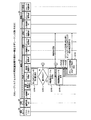
図2は、第1の制御ユニット111等のハードウェア構成例を示すブロック図である。図2において、第1の制御ユニット111等は、CPU(Central Processing Unit)201と、メモリ202と、I/F(Interface)203と、を有する。また、各構成部はバス210によってそれぞれ接続されている。
FIG. 2 is a block diagram illustrating a hardware configuration example of the
ここで、CPU201は、第1の制御ユニット111等の全体の制御を司る。メモリ202は、例えば、ROM(Read Only Memory)、RAM(Random Access Memory)およびフラッシュROMなどを有している。より具体的には、例えば、フラッシュROMがOSやファームウェアなどのプログラムを記憶し、ROMがアプリケーションプログラムを記憶し、RAMがCPU201のワークエリアとして使用される。メモリ202に記憶されているプログラムは、CPU201にロードされることで、コーディングされている処理をCPU201に実行させることになる。
Here, the
I/F203は、他のコンピュータからのデータの入出力を制御する。具体的には、例えば、I/F203は、通信回線を通じてLAN(Local Area Network)、WAN(Wide Area Network)、インターネットなどのネットワークに接続され、このネットワークを介して他のコンピュータに接続される。そして、I/F203は、ネットワークと内部のインターフェースを司り、他のコンピュータからのデータの入出力を制御する。
The I /
(第1の制御ユニット111の機能的構成例)
図3は、第1の制御ユニット111の機能的構成例を示すブロック図である。図3において、第1の制御ユニット111は、記憶部301と、算出部302と、判定部303と、作成部304と、再配置制御部305と、を含む構成である。算出部302〜再配置制御部305は、具体的には、例えば、図2に示したメモリ202に記憶されたプログラムをCPU201に実行させることにより、または、I/F203により、その機能を実現する。また、各機能部の処理結果は、例えば、メモリ202に記憶される。
(Functional configuration example of the first control unit 111)
FIG. 3 is a block diagram illustrating a functional configuration example of the
記憶部301は、第1のストレージ113の記憶領域の構成および第2のストレージ123の記憶領域の構成を示す構成情報を記憶する。この構成情報の中には、第1のストレージ113の記憶領域の割当状況および第2のストレージ123の記憶領域の割当状況を含む割当情報が含まれている。ここで、割当情報は、例えば、ボリュームが第1および第2のストレージ113,123内のどの記憶装置Dに割り当てられているかを示す情報である。
The
また、ボリュームは、ストレージシステムSMの管理単位となる記憶領域である。具体的には、例えば、ボリュームは、複数の物理的な記憶装置または記憶装置(例えば、ハードディスク)内のパーティションをグループ化して、仮想的に一つのボリュームとした論理ボリュームであってもよい。 The volume is a storage area that is a management unit of the storage system SM. Specifically, for example, the volume may be a logical volume that virtually groups a plurality of physical storage devices or partitions in a storage device (for example, a hard disk) into a single volume.
詳細な説明は図6を用いて後述するが、例えば、ボリュームは、複数のセグメントセットの集合体であり、各セグメントセットは、複数のセグメントの集合体である。この場合、構成情報は、ボリュームを構成する各セグメントが第1および第2のストレージ113,123内のどの記憶装置Dに割り当てられているかを示す情報となる。
The detailed description will be given later with reference to FIG. 6. For example, a volume is an aggregate of a plurality of segment sets, and each segment set is an aggregate of a plurality of segments. In this case, the configuration information is information indicating to which storage device D in each of the first and
構成情報は、例えば、第1のストレージ制御部114のメモリ202や第1のストレージ113に記憶されている。第1の制御ユニット111は、例えば、第1のストレージ制御部114のメモリ202から構成情報を読み出して記憶部301に記憶する。また、構成情報は、例えば、第1および第2のストレージ113,123の記憶領域の割当状況に応じて更新される。
The configuration information is stored in, for example, the
なお、構成情報は、冗長化のために第2のストレージ制御部124のメモリ202や第2のストレージ123にも記憶されることにしてもよい。構成情報の具体例については、後述する図8〜図10を用いて後述する。記憶部301は、例えば、第1の制御ユニット111のメモリ202により実現される。
Note that the configuration information may be stored in the
算出部302は、記憶部301に記憶された構成情報に基づいて、第1および第2のストレージ113,123にそれぞれ含まれる記憶装置D間における割当中の記憶領域の記憶容量の差分dを算出する。なお、以下の説明では、割当中の記憶領域の記憶容量を「割当量q」と表記する場合がある。
Based on the configuration information stored in the
具体的には、例えば、算出部302は、第1および第2のストレージ113,123に含まれる複数の記憶装置Dのうち、割当量qが最大となる記憶装置Dの最大割当量qmaxを算出する。また、算出部302は、複数の記憶装置Dのうち、割当量qが最小となる記憶装置Dの最小割当量qminを算出する。そして、算出部302は、最大割当量qmaxと最小割当量qminとの差分dを算出することにしてもよい。
Specifically, for example, the
なお、各記憶装置Dの割当量qは、例えば、各記憶装置Dに割り当てられているボリュームのセグメント数から求めることができる。例えば、セグメントの容量を256[MB]とし、ある記憶装置Dに割り当てられているセグメント数が「2」の場合、この記憶装置Dの割当量qは512[MB]となる。セグメントは、所定容量で規定された管理単位の記憶領域であり、ホストからボリュームへの記録再生指示アドレス(LBA)等の位置情報で管理される。 The allocation amount q of each storage device D can be obtained from the number of segments of the volume allocated to each storage device D, for example. For example, when the segment capacity is 256 [MB] and the number of segments allocated to a certain storage device D is “2”, the allocated amount q of this storage device D is 512 [MB]. A segment is a storage area of a management unit defined by a predetermined capacity, and is managed by position information such as a recording / playback instruction address (LBA) from the host to the volume.
判定部303は、算出部302によって算出された差分dに基づいて、第1および第2のストレージ113,123の記憶領域の割当状況に所定の偏りがあるか否かを判定する。ここで、所定の偏りがある状態とは、第1および第2のストレージ113,123における割当中の記憶領域(例えば、セグメント)を再配置したほうが望ましい程度に記憶領域の割当状況が偏っている状態である。
Based on the difference d calculated by the
具体的には、例えば、判定部303は、最大割当量qmaxと最小割当量qminとの差分dが、最大割当量qmaxの所定の割合α以上の場合に、第1および第2のストレージ113,123の記憶領域の割当状況に所定の偏りがあると判定することにしてもよい。また、判定部303は、算出された最大割当量qmaxと最小割当量qminとの差分dが、所定のサイズβ以上の場合に、第1および第2のストレージ113,123の記憶領域の割当状況に所定の偏りがあると判定することにしてもよい。
Specifically, for example, the
さらに、判定部303は、最大割当量qmaxと最小割当量qminとの差分dが、最大割当量qmaxの所定の割合α以上の場合、かつ、所定のサイズβ以上の場合に、第1および第2のストレージ113,123の記憶領域の割当状況に所定の偏りがあると判定することにしてもよい。
Further, the
既設のストレージユニットに比べて記憶容量の大きなストレージユニットを増設した場合には、増設したストレージユニットに多くのセグメントが配分されてしまう場合がある。このため、判定部303は、上述したように、使用可能な記憶容量に対する使用量から得られる使用率ではなく、割当量、すなわち、絶対使用量の比較を用いて、第1および第2のストレージ113,123の記憶領域の割当状況に所定の偏りがあるか否かを判定する。
When a storage unit having a larger storage capacity than that of an existing storage unit is added, many segments may be distributed to the added storage unit. Therefore, as described above, the
なお、第2のストレージユニット122の増設直後は、第2のストレージ123に対する記憶領域の割当が行われておらず、第2のストレージ123の割当量(割当中の記憶領域の記憶容量)は0である。このため、判定部303は、割当量qの差分dを検出することにより、第1および第2のストレージ113,123の記憶領域の割当量の偏りを容易に検出することができる。
Immediately after the
判定部303による判定処理は、例えば、予め設定された時間間隔で定期的に行われてもよく、また、ストレージシステムSMの管理者等の操作入力により任意のタイミングで行われてもよい。なお、割合αおよびサイズβは、例えば、メモリ202に記憶されている。また、割合αおよびサイズβの具体的な値については後述する。
The determination process by the
作成部304は、記憶部301に記憶された構成情報に基づいて、第1および第2のストレージ113,123の間で割当量qが均等になるような再配置計画を作成する。ここで、再配置計画とは、例えば、ボリュームを構成するセグメントを、どのストレージのどの記憶装置Dに再配置するかを表すものである。具体的には、例えば、作成部304は、第1および第2のストレージ113,123に含まれる記憶装置D間で割当量qが均等になるような再配置計画を作成する。
The
また、作成部304は、記憶部301に記憶された構成情報に基づいて、第1および第2のストレージ113,123の各ストレージにおいて再配置によるデータ移動のためのコピー処理が少なくなるような再配置計画を作成することにしてもよい。作成された再配置計画は、例えば、後述の図11に示す再配置計画テーブル720に記憶される。
In addition, the
再配置制御部305は、第1のストレージ113における記憶領域の割当量qと第2のストレージ123における記憶領域の割当量qとの間に生じた偏りの度合いに応じて、記憶部301に記憶された構成情報に基づき割当中の記憶領域の再配置制御を行う。具体的には、例えば、再配置制御部305は、第1および第2のストレージユニット112,122を制御して、作成部304によって作成された再配置計画に従って、第1および第2のストレージ113,123における割当中の記憶領域の配置を再配置する。
The
より具体的には、例えば、再配置制御部305は、第1のストレージ筐体101に第2の制御ユニット121および第2のストレージユニット122が接続されて記憶容量の拡張処理が行われたことを検出したときに割当中の記憶領域の再配置制御を行う。なお、拡張処理とは、例えば、第1のストレージ筐体101に接続された第2のストレージユニット122の第2のストレージ123を利用可能な状態にする処理である。この場合、再配置制御部305は、例えば、第1のストレージ113における割当中の記憶領域の一部の配置を第2のストレージ123における未割当の記憶領域に再配置する再配置制御を行う。
More specifically, for example, the
また、再配置制御部305は、例えば、第1のストレージ113または第2のストレージ123に記憶装置Dが追加されたことを検出したときに割当中の記憶領域の再配置制御を行うことにしてもよい。また、再配置制御部305は、例えば、判定部303によって所定の偏りがあると判定された場合に、第1および第2のストレージ113,123における割当中の記憶領域の配置を再配置する制御を行うことにしてもよい。
In addition, the
また、再配置制御部305は、他のストレージユニットから第1のストレージユニット112へのデータ移行処理中に第2の制御ユニット121および第2のストレージユニット122が接続されて記憶容量の拡張処理が行われたことを検出したときに割当中の記憶領域の再配置制御を行うことにしてもよい。この場合、再配置制御部305は、例えば、第1のストレージ113における割当中の記憶領域の一部の配置を第2のストレージ123における未割当の記憶領域に再配置する再配置制御を行う。
In addition, the
(第1の制御ユニット111の再配置制御処理手順)
つぎに、第1の制御ユニット111の再配置制御処理手順について説明する。まず、図4Aを用いて、第1の制御ユニット111の第1再配置制御処理手順について説明する。第1再配置制御処理は、ストレージシステムSMがスケールアウトされた場合に実行される再配置制御処理の一例である。
(Relocation control processing procedure of the first control unit 111)
Next, the rearrangement control processing procedure of the
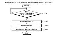
図4Aは、第1の制御ユニット111の第1再配置制御処理手順の一例を示すフローチャートである。図4Aのフローチャートにおいて、まず、第1の制御ユニット111は、第1のストレージ筐体101に第2のストレージ筐体102(第2の制御ユニット121、第2のストレージユニット122)が接続されて第2のストレージ123が利用可能な状態になったか否かを判断する(ステップS411)。
FIG. 4A is a flowchart illustrating an example of a first rearrangement control processing procedure of the
ここで、第1の制御ユニット111は、第2のストレージ123が利用可能な状態になるのを待つ(ステップS411:No)。第2のストレージ123が利用可能な状態になった場合(ステップS411:Yes)、第1の制御ユニット111は、第1のストレージ制御部114のメモリ202から構成情報を読み出す(ステップS412)。
Here, the
そして、第1の制御ユニット111は、読み出した構成情報に基づいて、第1および第2のストレージ113,123に含まれる記憶装置D間で割当量qが均等になるような再配置計画を作成する(ステップS413)。
Then, the
つぎに、第1の制御ユニット111は、第1および第2のストレージユニット112,122を制御して、作成した再配置計画に従って、第1および第2のストレージ113,123における割当中の記憶領域の配置を再配置する(ステップS414)。そして、第1の制御ユニット111は、本フローチャートによる一連の処理を終了する。
Next, the
これにより、ストレージシステムSMがスケールアウトされた場合に、第1および第2のストレージ113,123における割当中の記憶領域の再配置制御を行うことができる。
Thereby, when the storage system SM is scaled out, the rearrangement control of the storage areas being allocated in the first and
つぎに、図4Bを用いて、第1の制御ユニット111の第2再配置制御処理手順について説明する。第2再配置制御処理は、任意のタイミング、あるいは、定期的に実行される再配置制御処理である。
Next, the second rearrangement control processing procedure of the
図4Bは、第1の制御ユニット111の第2再配置制御処理手順の一例を示すフローチャートである。図4Bのフローチャートにおいて、まず、第1の制御ユニット111は、
第1のストレージ制御部114のメモリ202から構成情報を読み出す(ステップS421)。
FIG. 4B is a flowchart illustrating an example of the second rearrangement control processing procedure of the
The configuration information is read from the
つぎに、第1の制御ユニット111は、読み出した構成情報に基づいて、第1および第2のストレージ113,123に含まれる複数の記憶装置Dのうち、割当量qが最大となる記憶装置Dの最大割当量qmaxを算出する(ステップS422)。つぎに、第1の制御ユニット111は、読み出した構成情報に基づいて、複数の記憶装置Dのうち、割当量qが最小となる記憶装置Dの最小割当量qminを算出する(ステップS423)。
Next, the
そして、第1の制御ユニット111は、最大割当量qmaxと最小割当量qminとの差分dを算出する(ステップS424)。つぎに、第1の制御ユニット111は、算出した差分dが最大割当量qmaxの割合α以上か否かを判断する(ステップS425)。ここで、差分dが最大割当量qmaxの割合α未満の場合(ステップS425:No)、第1の制御ユニット111は、本フローチャートによる一連の処理を終了する。
Then, the
一方、差分dが最大割当量qmaxの割合α以上の場合(ステップS425:Yes)、第1の制御ユニット111は、差分dがサイズβ以上か否かを判断する(ステップS426)。ここで、差分dがサイズβ未満の場合(ステップS426:No)、第1の制御ユニット111は、本フローチャートによる一連の処理を終了する。
On the other hand, when the difference d is equal to or larger than the ratio α of the maximum allocation amount q max (step S425: Yes), the
一方、差分dがサイズβ以上の場合(ステップS426:Yes)、第1の制御ユニット111は、構成情報に基づいて、第1および第2のストレージ113,123に含まれる記憶装置D間で割当量qが均等になるような再配置計画を作成する(ステップS427)。
On the other hand, when the difference d is equal to or larger than the size β (step S426: Yes), the
つぎに、第1の制御ユニット111は、第1および第2のストレージユニット112,122を制御して、作成した再配置計画に従って、第1および第2のストレージ113,123における割当中の記憶領域の配置を再配置する(ステップS428)。そして、第1の制御ユニット111は、本フローチャートによる一連の処理を終了する。
Next, the
これにより、任意のタイミング、あるいは、定期的に、第1および第2のストレージ113,123の記憶領域の割当状況を判定して、第1および第2のストレージ113,123における割当中の記憶領域の再配置制御を行うことができる。例えば、第2のストレージユニット122の増設直後は、第1および第2のストレージ113,123間の割当量の偏りが判定されるが、増設後の運用中は、第1および第2のストレージ113,123を合わせたシステム全体のストレージにおける記憶装置間で割当量の偏りが判定できる。すなわち、例えば、第1のストレージ113内の記憶装置間で偏りができている場合も判定できる。
Thereby, the allocation status of the storage areas of the first and
以上説明したように、実施の形態にかかる第1のストレージ筐体101の第1の制御ユニット111によれば、第1および第2のストレージ113,123において生じた割当量qの偏りの度合いに応じて、割当中の記憶領域の再配置制御を行うことができる。これにより、ストレージシステムSMに格納されたデータに対するアクセス性能の最適化を図ることができる。
As described above, according to the
また、第1の制御ユニット111によれば、第1のストレージ筐体101に第2のストレージ筐体102(第2の制御ユニット121、第2のストレージユニット122)が接続されて記憶容量の拡張処理が行われたときに、第1のストレージ113における割当中の記憶領域の一部の配置を第2のストレージ123における未割当の記憶領域に再配置する再配置制御を行うことができる。これにより、ストレージシステムSMがスケールアウトされた場合に、システム構成の変更前に格納されたデータに対するアクセス性能の最適化を図ることができる。
Further, according to the
また、第1の制御ユニット111によれば、第1および第2のストレージ113,123に含まれる記憶装置D間で割当量qが均等になるように、第1および第2のストレージ113,123における割当中の記憶領域の再配置制御を行うことができる。これにより、第1および第2のストレージユニット112,122間でデータに対するアクセスが均等になるように分散することができる。
In addition, according to the
また、第1の制御ユニット111によれば、第1および第2のストレージ113,123に含まれる記憶装置Dの最大割当量qmaxと記憶装置Dの最小割当量qminとの差分dを算出することができる。また、第1の制御ユニット111によれば、算出した差分dが、最大割当量qmaxの所定の割合α以上の場合、かつ、所定のサイズβ以上の場合に、第1および第2のストレージ113,123の記憶領域の割当状況に所定の偏りがあると判定することができる。これにより、第1および第2のストレージ113,123における割当中の記憶領域を再配置したほうが望ましい程度にストレージ間の記憶領域の割当状況が偏っているか否かを判断することができる。
Further, according to the
また、第1の制御ユニット111によれば、他のストレージユニットから第1のストレージユニット112へのデータ移行処理中に第2の制御ユニット121および第2のストレージユニット122が接続されて記憶容量の拡張処理が行われたときに、第1のストレージ113における割当中の記憶領域の一部の配置を第2のストレージ123における未割当の記憶領域に再配置する再配置制御を行うことができる。これにより、データ移行中にストレージシステムSMがスケールアウトされても、システム構成の変更前に格納されたデータに対するアクセス性能の最適化を図ることができる。
Further, according to the
(実施例1)
つぎに、実施の形態にかかるストレージシステムSMの実施例1について説明する。
Example 1
Next, Example 1 of the storage system SM according to the embodiment will be described.
(ストレージシステムSMのシステム構成例)
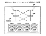
図5は、実施例1にかかるストレージシステムSMのシステム構成例を示す説明図である。図5において、ストレージシステムSMは、PU(Processor Unit)#1と、PU#2と、SW(Switch)#1と、SW#2と、SU(Storage Unit)#1と、を含む。
(System configuration example of storage system SM)
FIG. 5 is an explanatory diagram of a system configuration example of the storage system SM according to the first embodiment. In FIG. 5, the storage system SM includes PU (Processor Unit) # 1,
ここで、PU#1,#2は、SU#1,#2を制御するコンピュータである。PU#1,#2は、例えば、後述する業務サーバBSや管理サーバMSがアクセス可能なサーバである。図1に示した第1の制御ユニット111は、例えば、PU#1に相当する。SW#1,#2は、スイッチング機能を有するコンピュータである。
Here,
SU#1は、RAID(Redundant Arrays of Inexpensive Disks)#1〜#4を有し、RAID#1〜#4に対するアクセスを制御するコンピュータである。図1に示した第1のストレージユニット112は、例えば、SU#1に相当する。
The
各RAID#1〜#4は、複数の記憶装置(例えば、ハードディスク)をまとめて一つの記憶装置としたRAIDグループである。具体的には、各RAID#1〜#4は、それぞれ2つのLUNで構成されている。図1に示した第1のストレージ113は、例えば、RAID#1〜#4に相当する。また、図1に示した記憶装置Dは、例えば、LUNに相当する。
Each
なお、ここでは冗長化のためにSU#1に2台のPU#1,#2が接続される場合を例に挙げて説明したが、SU#1には1台のPU(例えば、PU#1またはPU#2)が接続されることにしてもよい。
Here, the case where two
ストレージシステムSMは、ストレージシステムSMに要求される記憶容量の増加にともなって、ストレージシステムSM全体の記憶領域を拡張することができる。具体的には、例えば、ストレージシステムSMでは、PUとSUを1セットとして、ストレージシステムSM全体の記憶領域を拡張することができる。 The storage system SM can expand the storage area of the entire storage system SM as the storage capacity required for the storage system SM increases. Specifically, for example, in the storage system SM, the storage area of the entire storage system SM can be expanded by setting PU and SU as one set.
以下の説明では、PUとSUを1セットとする拡張セット(PU+SU)を、ストレージシステムSMに追加することを「スケールアウト」と表記する場合がある。また、ストレージシステムSMに含まれるPU#1,#2とSW#1,#2とSU#1を「基本ノード」と表記し、ストレージシステムSMに追加される拡張セットを「増設ノード」と表記する場合がある。また、ストレージシステムSMにより提供される仮想的なボリュームを「VDISK」と表記する場合がある。
In the following description, adding an expansion set (PU + SU) including one PU and SU to the storage system SM may be referred to as “scale-out”. In addition,
(VDISKの構成例)
図6は、VDISKの構成例を示す説明図である。図6において、VDISKは、複数のセグメントセットの集合体である。各セグメントセットは、8個のセグメント#1〜#8の集合体である。ここでは、各セグメントセットの容量は、例えば、2[GB]であり、また、各セグメントの容量は、例えば、256[MB]である。
(Configuration example of VDISK)
FIG. 6 is an explanatory diagram showing a configuration example of VDISK. In FIG. 6, VDISK is an aggregate of a plurality of segment sets. Each segment set is an aggregate of eight
図5に示したストレージシステムSMを例に挙げると、各セグメント#1〜#8は、SU#1内のLUN#1〜#8ごとに割り当てられる。ユーザのデータは、固定長のストリップ(1[MB])単位で記録される。また、このストリップはセグメント#1〜#8を順に利用する形でストライピングされる。
Taking the storage system SM shown in FIG. 5 as an example, the
(ストレージシステムSM内のPUの機能的構成例)
図7は、実施例1にかかるPUの機能的構成例を示す説明図である。図7において、ストレージシステムSMは、基本ノードN1と、増設ノードN2と、を含む。図1に示した第1のストレージ装置101は、例えば、基本ノードN1に相当する。また、図1に示した第2のストレージ装置102は、増設ノードN2に相当する。ただし、図7では、スケールアウト直後のストレージシステムSMの状態を表す。基本ノードN1は、PU#1と、PU#2と、SU#1と、を含む。増設ノードN2は、PU#3と、SU#2と、を含む。
(Functional configuration example of PU in storage system SM)
FIG. 7 is an explanatory diagram of a functional configuration example of the PU according to the first embodiment. In FIG. 7, the storage system SM includes a basic node N1 and an additional node N2. The
基本ノードN1内のPU#1,#2と、増設ノードN2内のPU#3と、管理サーバMSとは、管理用LANを介して接続される。管理サーバMSは、ストレージシステムSMの管理者が使用するコンピュータであり、装置管理GUI(Graphical User Interface)を有する。
The
また、基本ノードN1内のPU#1,#2と、増設ノードN2内のPU#3と、業務サーバBSとは、I/O用LANを介して接続される。業務サーバBSは、業務用のアプリケーションがインストールされたコンピュータである。
The
また、PU#1,#2,#3と、SU#1,#2とは、I/O用LANおよび内部管理LANを介して接続される。各SU#1,#2は、構成管理DB#1,#2と、ストレージ制御部#1,#2とを有する。ストレージ制御部#1,#2は、ストレージ制御プログラムをCPUが実行することにより実現される。ストレージ制御プログラムは、各SU#1,#2内のストレージに対するアクセスを制御するプログラムである。
The
構成管理DB#1,#2には、ボリューム管理テーブル710と再配置計画テーブル720が含まれる。ボリューム管理テーブル710と再配置計画テーブル720は、PU#1によって構成管理DB#1(または、構成管理DB#2)から読み出されて使用される。ここで、ボリューム管理テーブル710は、ボリュームインデックステーブル800(図8参照)と、ミラーボリュームインデックステーブル900(図9参照)と、ボリュームセグメントテーブル1000(図10参照)と、を含む。
The configuration
ボリュームインデックステーブル800は、ボリューム(VDISK)を管理するテーブルである。ミラーボリュームインデックステーブル900は、ミラーボリュームを管理するテーブルである。ボリュームセグメントテーブル1000は、ボリュームのセグメントを管理するテーブルである。各テーブル800,900,1000は、ボリューム番号をインデックスとして関連付けられている。 The volume index table 800 is a table for managing volumes (VDISK). The mirror volume index table 900 is a table for managing mirror volumes. The volume segment table 1000 is a table for managing volume segments. Each table 800, 900, 1000 is associated with a volume number as an index.
また、再配置計画テーブル720は、VDISKを構成する各セグメントをどこへ配置するかを計画した計画後の配置先のストレージ装置(SU)、LUN番号および再配置状況を管理するテーブルである。既に再配置が完了した(もしくは、再配置が不要な)セグメントの再配置状況については「再配置完了(もしくは、再配置不要)」とする。また、現状再配置中のセグメントの再配置状況については「再配置中」とし、今後再配置されるセグメントの再配置状況については「再配置待」とする。 The rearrangement plan table 720 is a table for managing the storage destination storage unit (SU), LUN number, and rearrangement status after planning where each segment constituting the VDISK is planned. The relocation status of a segment that has already been relocated (or that does not require relocation) is assumed to be “relocation complete (or relocation unnecessary)”. In addition, the relocation status of the segment that is currently being relocated is “relocating”, and the relocation status of the segment to be relocated in the future is “waiting for relocation”.
再配置の一時停止中は、PU#1は、再配置計画テーブル720を削除することなく保持しておく。再配置が停止された場合は、PU#1は、再配置計画テーブル720を破棄する。また、再配置の一時停止中にボリューム(VDISK)が削除された場合、PU#1は、ボリューム管理テーブル710のボリュームインデックステーブル800から該当レコードを削除するとともに、再配置計画テーブル720から該当レコードを削除する。なお、ボリューム管理テーブル710と再配置計画テーブル720についての詳細な説明は、図8〜図11を用いて後述する。
While the rearrangement is suspended,
PU#1は、I/O制御部#1と、PU制御部#1と、クラスタ制御Mと、装置管理GUI制御部#1と、PU負荷監視部#1と、SU制御部#1と、ボリューム管理Mと、ボリューム管理A#1と、を含む。図3に示した算出部302、判定部303、作成部304および再配置制御部305は、例えば、ボリューム管理Mに相当する。
また、PU#2は、I/O制御部#2と、PU制御部#2と、クラスタ制御部#2と、PU負荷監視部#2と、SU制御部#2と、ボリューム管理A#2と、を含む。また、PU#3は、I/O制御部#3と、PU制御部#3と、クラスタ制御部#3と、PU負荷監視部#3と、SU制御部#3と、ボリューム管理A#3と、を含む。
In addition,
ここで、I/O制御部#1〜#3は、業務サーバBSからのI/O要求を受け付けて処理する。PU制御部#1〜#3は、各PU#1〜#3を制御する。クラスタ制御Mは、PU同士をクラスタリングする。ここでは、PU#1とPU#2とPU#3とでクラスタが形成されている。クラスタ制御部#2,#3は、クラスタ制御MによってクラスタリングされたPU#1〜#3を認識する。
Here, the I / O
装置管理GUI制御部#1は、管理サーバMSからの指示に従って、ストレージシステムSMの状態を判断したり、新規ボリュームを作成したりする。PU負荷監視部#1〜#3は、各PU#1〜#3にかかる負荷を監視する。SU制御部#1〜#3は、各SU#1,#2を制御する。
The device management GUI
ボリューム管理Mは、ボリューム管理A#1〜#3を制御する。具体的には、例えば、ボリューム管理Mは、再配置制御スレッドを起動して、ボリューム管理A#1〜#3に実行させる。ボリューム管理A#1〜#3は、ボリューム管理Mの制御に従って、ボリュームを管理する。
Volume management M controls volume management A # 1- # 3. Specifically, for example, the volume management M activates the rearrangement control thread and causes the volume
なお、ストレージシステムSMにおいて、PU#1がダウンした場合は、例えば、PU#2またはPU#3が、PU#1の機能を引き継ぐ。また、業務サーバBS、管理サーバMSのハードウェア構成は、例えば、CPU、メモリ、磁気ディスクドライブ、磁気ディスク、ディスプレイ、I/F、キーボード、マウス等により実現される。
In the storage system SM, when
(ボリューム管理テーブル710の記憶内容)
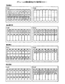
つぎに、図8〜図10を用いて、ボリューム管理テーブル710の記憶内容について説明する。上述した構成情報は、例えば、ボリューム管理テーブル710に相当する。
(Storage contents of volume management table 710)
Next, the contents stored in the volume management table 710 will be described with reference to FIGS. The configuration information described above corresponds to the volume management table 710, for example.
図8は、ボリュームインデックステーブル800の記憶内容の一例を示す説明図である。図8において、ボリュームインデックステーブル800は、ボリューム番号、ボリューム名、稼働PU番号、ボリューム属性、ボリュームサイズ、ボリューム状態および再配置状況のフィールドを有する。各フィールドに情報を設定することで、ボリューム情報800−1〜800−nがレコードとして記憶される。 FIG. 8 is an explanatory diagram showing an example of the contents stored in the volume index table 800. In FIG. 8, a volume index table 800 has fields for volume number, volume name, active PU number, volume attribute, volume size, volume status, and relocation status. By setting information in each field, the volume information 800-1 to 800-n is stored as a record.
ここで、ボリューム番号は、VDISKの識別子である。ボリューム名は、VDISKの名称である。稼働PU番号は、VDISKが稼働しているPUの識別子である。ボリューム属性は、VDISKの属性である。ボリュームサイズは、業務サーバBSからみたVDISKのサイズ(GB)である。ボリューム状態は、VDISKにアクセスできるか否かを示す状態である。再配置状況は、VDISKの再配置状況を示す。 Here, the volume number is an identifier of VDISK. The volume name is the name of VDISK. The operating PU number is an identifier of the PU in which VDISK is operating. The volume attribute is an attribute of VDISK. The volume size is the size (GB) of VDISK viewed from the business server BS. The volume state is a state indicating whether or not the VDISK can be accessed. The rearrangement status indicates the rearrangement status of VDISK.
例えば、ボリューム情報800−1は、VDISK1のボリューム名「Vdisk1」、稼働PU番号「1」、ボリューム属性「シンプロボリューム」、ボリュームサイズ「500」、ボリューム状態「正常」および再配置状況「再配置中」を示している。なお、ボリューム情報800−nのように、ボリューム名が「NULL」のボリューム情報は、未作成のVDISKの情報である。 For example, the volume information 800-1 includes a volume name “Vdisk1”, an operation PU number “1”, a volume attribute “Sinpro volume”, a volume size “500”, a volume state “normal”, and a relocation status “relocating”. Is shown. Note that the volume information with the volume name “NULL”, such as the volume information 800-n, is uncreated VDISK information.
図9は、ミラーボリュームインデックステーブル900の記憶内容の一例を示す説明図である。図9において、ミラーボリュームインデックステーブル900は、ボリューム番号、ミラー数、ミラーボリューム番号1およびミラーボリューム番号2のフィールドを有する。各フィールドに情報を設定することで、ミラーボリューム情報(例えば、ミラーボリューム情報900−1,900−2)がレコードとして記憶される。
FIG. 9 is an explanatory diagram showing an example of the contents stored in the mirror volume index table 900. In FIG. 9, the mirror volume index table 900 has fields of volume number, number of mirrors,
ここで、ボリューム番号は、ミラーボリュームの識別子である。ミラー数は、ミラーリングするボリュームの数である。ミラーボリューム番号1,2は、ミラーボリュームの実体であるVDISKの識別子である。例えば、ミラーボリューム情報900−1は、VDISK5のミラー数「2」、ミラーボリューム番号1「127」およびミラーボリューム番号2「128」を示している。
Here, the volume number is an identifier of the mirror volume. The number of mirrors is the number of volumes to be mirrored. The
図10は、ボリュームセグメントテーブル1000の記憶内容の一例を示す説明図である。図10において、ボリュームセグメントテーブル1000は、ボリューム番号、セグメントセット番号、セグメント番号、ストレージ装置、LUN番号、セグメント状態および再配置状況のフィールドを有する。各フィールドに情報を設定することで、セグメント情報(例えば、セグメント情報1000−1,1000−2)がレコードとして記憶される。 FIG. 10 is an explanatory diagram showing an example of the contents stored in the volume segment table 1000. In FIG. 10, the volume segment table 1000 has fields for volume number, segment set number, segment number, storage device, LUN number, segment status, and relocation status. By setting information in each field, segment information (for example, segment information 1000-1, 1000-2) is stored as a record.
ここで、ボリューム番号は、VDISKの識別子である。セグメントセット番号は、VDISKを構成するセグメントセットの識別子である。セグメント番号は、セグメントセットを構成するセグメントの識別子である。ストレージ装置は、セグメントが属するSUの識別子である。LUN番号は、セグメントが割り当てられたLUNの識別子である。セグメント状態は、セグメントにアクセスできるか否かを示す状態である。再配置状況は、セグメントの再配置状況を示す。 Here, the volume number is an identifier of VDISK. The segment set number is an identifier of a segment set that constitutes VDISK. The segment number is an identifier of a segment constituting the segment set. The storage device is the identifier of the SU to which the segment belongs. The LUN number is an identifier of the LUN to which the segment is assigned. The segment state is a state indicating whether or not the segment can be accessed. The rearrangement status indicates a segment rearrangement status.
例えば、セグメント情報1000−1は、VDISK1のセグメントセット1のセグメント1のストレージ装置「1」、LUN番号「1」、セグメント状態「有効」および再配置状況「ブランク(空)」を示している。
For example, the segment information 1000-1 indicates the storage device “1”, the LUN number “1”, the segment state “valid”, and the rearrangement status “blank (empty)” of the
(再配置計画テーブル720の記憶内容)
つぎに、図11を用いて、再配置計画テーブル720の記憶内容について説明する。
(Storage contents of the rearrangement plan table 720)
Next, the storage contents of the rearrangement plan table 720 will be described with reference to FIG.
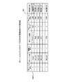
図11は、再配置計画テーブル720の記憶内容の一例を示す説明図である。図11において、再配置計画テーブル720は、ボリューム番号、セグメントセット番号、セグメント番号、現ストレージ装置、現LUN番号、再配置ストレージ装置、再配置LUN番号および再配置状況のフィールドを有する。各フィールドに情報を設定することで、再配置計画情報(例えば、再配置計画情報1100−1〜1100−5)がレコードとして記憶される。 FIG. 11 is an explanatory diagram showing an example of the stored contents of the rearrangement plan table 720. In FIG. 11, the relocation plan table 720 includes fields for volume number, segment set number, segment number, current storage device, current LUN number, relocation storage device, relocation LUN number, and relocation status. By setting information in each field, rearrangement plan information (for example, rearrangement plan information 1100-1 to 1100-5) is stored as a record.
ここで、ボリューム番号は、VDISKの識別子である。セグメントセット番号は、VDISKを構成するセグメントセットの識別子である。セグメント番号は、セグメントセットを構成するセグメントの識別子である。現ストレージ装置は、再配置前のセグメントが属するSUの識別子である。現LUN番号は、再配置前のセグメントが割り当てられたLUNの識別子である。再配置ストレージ装置は、再配置後のセグメントが属するSUの識別子である。再配置LUN番号は、再配置後のセグメントが割り当てられるLUNの識別子である。再配置状況は、セグメントの再配置状況を示す。 Here, the volume number is an identifier of VDISK. The segment set number is an identifier of a segment set that constitutes VDISK. The segment number is an identifier of a segment constituting the segment set. The current storage device is the identifier of the SU to which the segment before relocation belongs. The current LUN number is an identifier of the LUN to which the segment before relocation is assigned. The rearranged storage device is the identifier of the SU to which the segment after rearrangement belongs. The rearranged LUN number is an identifier of a LUN to which a segment after rearrangement is assigned. The rearrangement status indicates a segment rearrangement status.
例えば、再配置計画情報1100−1は、VDISK1のセグメントセット1のセグメント1の現ストレージ装置「1」、現LUN番号「1」、再配置ストレージ装置「1」、再配置LUN番号「1」および再配置状況「再配置不要」を示している。
For example, the relocation plan information 1100-1 includes the current storage device “1”, the current LUN number “1”, the relocation storage device “1”, the relocation LUN number “1”, and the
(セグメントの割当量qの偏りの判定例)
つぎに、ストレージシステムSM内の各LUNのセグメントの割当量qの偏りの判定例について説明する。PU#1は、ストレージシステムSM内の各LUNのセグメントの割当量qを監視し、「偏りあり」と検出した場合に、装置管理GUI制御部により、偏りが発生している旨を通知する。監視契機としては、例えば、ノードの増設にともなうシステム構成変更時、定期的な監視時間の到来、SUの搭載量の増加時などがある。
(Judgment example of segment allocation q bias)
Next, a description will be given of a determination example of the deviation of the allocated amount q of each LUN segment in the storage system SM.
具体的には、例えば、まず、PU#1は、ボリューム管理テーブル710を参照して、ストレージシステムSM内の各LUNのセグメントの割当量qを算出する。つぎに、PU#1は、ストレージシステムSM内の全LUNのうち、セグメントの割当量qが最大であるLUNの最大割当量qmaxとセグメントの割当量qが最小であるLUNの最小割当量qminとを特定する。
Specifically, for example, first,
そして、PU#1は、最大割当量qmaxと最小割当量qminとの差分dが、最大割当量qmaxの所定の割合α以上、かつ、差分dが所定のサイズβ以上である場合に、ストレージシステムSM内の各LUNのセグメントの割当量qに偏りがあると判定する。所定の割合αおよびサイズβは、任意に設定可能である。割合αは、例えば、5〜10[%]程度の値に設定される。サイズβは、例えば、64[GB]や128[GB]程度の値に設定される。
(ボリュームの再配置計画)
つぎに、ボリューム(VDISK)の再配置計画について説明する。PU#1は、SUを構成するLUNにおけるセグメントの割当量qにより再配置計画を立てる。このため、増設されるSUの搭載容量が既存のSUの搭載容量と異なる場合であっても均等な再配置を行うことができる。
(Volume relocation plan)
Next, a volume (VDISK) relocation plan will be described. The
図12は、ボリュームの再配置計画例を示す説明図である。図12の1項に示すように、8.4[TB]の基本セット(SU#1)に、8.4[TB]の拡張セット(SU#2)を増設する場合を想定する。この場合、PU#1は、SU#1とSU#2との間で各LUNのセグメントの割当量qが均等になるように分散配置する。
FIG. 12 is an explanatory diagram of an example of a volume relocation plan. As shown in
図12の2項に示すように、8.4[TB]の基本セット(SU#1)に、16.8[TB]の拡張セット(SU#2)を増設する場合を想定する。この場合、PU#1は、SU#1とSU#2との間で各LUNのセグメントの割当量qが均等になるように分散配置する。
As shown in
図12の3項に示すように、8.4[TB]の基本セット(SU#1)と8.4[TB]の拡張セット(SU#2)に、16.8[TB]の拡張セット(SU#3)を増設する場合を想定する。この場合、PU#1は、SU#1とSU#2とSU#3との間で各LUNのセグメントの割当量qが均等になるように分散配置する。なお、ここでは、PUとSUを1セットとする拡張セットを増設する場合について説明したが、SUのみを拡張セットとして増設することにしてもよい。
As shown in
ここで、図13を用いて、スケールアウトによって増設されるSU#2に対して、既存のボリュームがどのように再配置されるのかを説明する。ここでは、スケールアウト後に自動で再配置処理が起動される場合について説明するが、管理サーバMSのGUI画面から再配置指示を手動で行うこともできる。
Here, how an existing volume is rearranged with respect to
図13は、ボリュームの再配置例を示す説明図(その1)である。図13において、ボリューム1を構成するセグメントA0〜A31と、ボリューム2を構成するセグメントB0〜B15とがSU#1に配置されている(図13中、再配置前)。なお、図13中、各SU#1,#2内の円柱は、各SU#1,#2内のLUNを表す。
FIG. 13 is an explanatory diagram (part 1) of an example of volume relocation. In FIG. 13, segments A0 to
まず、PU#1は、SU#1とSU#2との間で各LUNのセグメントの割当量qが均等になるように再配置計画テーブル720を作成する(図13中、再配置の案)。なお、各セグメントの配置位置は暫定的なものである。
First,
つぎに、PU#1は、再配置計画テーブル720を参照して、ボリューム1のセグメントA0〜A31について再配置する。ここでは、ボリューム1のセグメントA8〜A15およびA24〜A31がSU#2に再配置されている(図13中、再配置中)。
Next,
つぎに、PU#1は、再配置計画テーブル720を参照して、ボリューム2のセグメントB0〜B15について再配置する。ここでは、ボリューム2のセグメントB8〜B15がSU#2に再配置されている(図13中、再配置後)。これにより、SU#1とSU#2とで物理容量としては均等となる。
Next,
なお、LUNの使用状況は不連続に見えるが、ボリュームがワイドストライピングされたセグメントで構成されていれば性能面で問題はない。すなわち、LUNの使用状況の不連続性は性能面に影響しない。このため、不要な移動処理を避ける意味でもセグメントA16〜A23やセグメントB0〜B7を移動させないほうが、装置として無駄な処理を削減することができる。 Although the LUN usage status appears discontinuous, there is no problem in terms of performance if the volume is composed of wide striped segments. That is, the discontinuity of the LUN usage status does not affect the performance. For this reason, in order to avoid unnecessary movement processing, it is possible to reduce unnecessary processing as an apparatus if the segments A16 to A23 and the segments B0 to B7 are not moved.
また、各PUや各SUの保守点検等で一時的に再配置処理を止めたい場合のために、ストレージシステムSMは、再配置処理の一時停止機能および再開機能を有する。また、ストレージシステムSMは、再配置処理の停止機能を有する。ただし、再配置処理を停止すると、一度計画した再配置計画を破棄することになり、再配置を再度実行する際に、ストレージシステムSM内の各LUNのセグメントの割当量qの偏り判定および再計画テーブル作成の処理が実行されることとなる。 In addition, the storage system SM has a temporary stop function and a restart function for the rearrangement process in order to temporarily stop the rearrangement process in the maintenance inspection of each PU or each SU. Further, the storage system SM has a relocation processing stop function. However, if the rearrangement process is stopped, the planned rearrangement plan is discarded, and when the rearrangement is executed again, the bias determination and the rearrangement of the allocated amount q of each LUN segment in the storage system SM are performed. The table creation process is executed.
これに対し、一時停止機能を利用した場合は、再配置の一時停止中、PU#1は、ボリュームの再配置のために立てた再配置計画を破棄せずに保持しておく。そして、PU#1は、再開指示を受けた場合に、ボリューム管理テーブル710および再配置計画テーブル720を参照して、再開すべきエントリから再配置処理を継続する。これにより、再配置中の一時停止および一時停止からの再開が可能となる。
On the other hand, when the suspension function is used,
(各種テーブル710,720の更新例)
つぎに、図14〜図17を用いて、各種テーブル710,720の更新例について説明する。
(Update examples of various tables 710 and 720)
Next, update examples of the various tables 710 and 720 will be described with reference to FIGS.
図14は、ボリュームの配置例を示す説明図である。図14において、VDISK1を構成するセグメント#1〜#16がSU#1に配置されている。また、基本ノードN1に、PU#3とSU#2をセットとする増設ノードN2が増設されている。この場合、ストレージシステムSM内の各LUNのセグメントの割当量qに偏りが生じるため、VDISK1の再配置処理が行われる。
FIG. 14 is an explanatory diagram of an example of volume arrangement. In FIG. 14,
図15は、ボリュームインデックステーブル800の更新例を示す説明図である。図15において、基本ノードN1に増設ノードN2が増設されると、ボリュームインデックステーブル800内のボリューム情報1500−1の再配置状況が「再配置待」から「再配置中」に更新される。 FIG. 15 is an explanatory diagram showing an example of updating the volume index table 800. In FIG. 15, when the expansion node N2 is added to the basic node N1, the relocation status of the volume information 1500-1 in the volume index table 800 is updated from “waiting for relocation” to “under relocation”.
図16は、ボリュームセグメントテーブル1000の更新例を示す説明図である。図16の(16−1)において、ボリュームセグメントテーブル1000には、ボリューム番号「1」のVDISK1のセグメント情報が記憶されている。セグメントセットを構成する8つのセグメントは、基本的には異なる8つのLUNに連続に配置される(例えば、図16中、実線枠)。 FIG. 16 is an explanatory diagram showing an example of updating the volume segment table 1000. In (16-1) of FIG. 16, the volume segment table 1000 stores the segment information of the VDISK1 with the volume number “1”. The eight segments constituting the segment set are basically arranged continuously in eight different LUNs (for example, a solid line frame in FIG. 16).
ただし、VDISK1を作成する前に作成済みのボリュームがあると、そのボリュームに割り当てられていたLUNを削除するタイミングでVDISK1にLUNが割り当てられる場合がある。この場合、連番でLUNが空いていないと、セグメントセットを構成するセグメントが配置されるLUNが平準化されないことがある(例えば、図16中、点線枠)。 However, if there is a volume that has been created before creating VDISK1, a LUN may be assigned to VDISK1 at the timing of deleting the LUN assigned to that volume. In this case, if the LUNs are serial numbers and the LUNs are not vacant, the LUNs in which the segments constituting the segment set are arranged may not be leveled (for example, a dotted frame in FIG. 16).
図16の(16−2)において、PU#1のボリューム管理Mは、再配置計画テーブル720(例えば、後述の図17参照)が作成されると、ボリュームセグメントテーブル1000の再配置状況を「再配置処理中」とする。つぎに、ボリューム管理Mは、再配置計画テーブル720を参照して、再配置状況が「再配置待ち」となっているセグメントについて、各PU用に再配置制御スレッドを生成し、再配置を実施する。
In (16-2) of FIG. 16, when the relocation plan table 720 (for example, see FIG. 17 to be described later) is created, the volume management M of
各PUの再配置制御スレッドは、再配置すべきセグメントについてボリューム管理Aに再配置のためのコピー処理を指示する。ボリューム管理Mは、ボリューム管理Aから再配置制御スレッドに対してコピー完了を応答してきたら、再配置計画テーブル720の再配置状況を「再配置完了」に変更するとともに、ボリュームセグメントテーブル1000の再配置状況を「ブランク」に変更する。 The relocation control thread of each PU instructs the volume management A to perform copy processing for relocation for the segment to be relocated. When the volume management M responds from the volume management A to the rearrangement control thread with a copy completion, the volume management M changes the rearrangement status of the rearrangement plan table 720 to “relocation complete” and rearranges the volume segment table 1000. Change the status to "blank".
図17は、再配置計画テーブル720の更新例を示す説明図である。図17の(17−1)において、PU#1は、VDISK1のセグメントセット単位ですべてのSUに割り付け、かつ、セグメントを割り付ける。また、PU#1は、LUN番号についても連続LUNを利用するように割り付けるように計画を立てる。具体的には、例えば、PU#1は、偶数セグメントをSU#2の連続LUNに割り付けるように計画する。また、PU#1は、奇数セグメントをSU#1の連続LUNに割り付けるように計画する。
FIG. 17 is an explanatory diagram illustrating an update example of the rearrangement plan table 720. In (17-1) of FIG. 17,
図17の(17−2)において、PU#1は、上述したように機械的に再配置計画を立てた後、再配置によるデータ移動のためのコピー処理が少なくなるように再配置計画の見直しを行う。具体的には、例えば、PU#1は、現状(現ストレージ装置および現LUN番号)と、再配置後(再配置ストレージ装置および再配置LUN番号)とをセグメントセット単位で比べる。
In (17-2) of FIG. 17,
例えば、セグメントセット番号3については、現LUN番号と再配置LUN番号がすべて不一致であるが、現LUN番号を見ると2つのセグメントが同じLUN番号に割り当たっている以外は、異なるLUNに割り振られている。このため、PU#1は、同じLUNに2つのセグメントが割り付けられているものだけをその他のLUNに割り振るように再計画する(LUN番号的にはセグメント順ではないが、異なるLUNに割り付けられているならば性能影響はないと判断)。
For example, for segment set
再配置すべきセグメントについては、PU#1は、再配置状況を「再配置待ち」とし、かつ、ボリュームセグメントテーブル1000の再配置状況を「再配置処理中」とする。また、再配置不要なセグメントについては、PU#1は、再配置計画テーブル720の再配置状況を「再配置不要」とする。
For the segment to be rearranged,
(同一SU内の再配置計画)
つぎに、同一SUにおいて再配置によるセグメント移動のためのコピー処理が少なくなるようにする再配置計画について説明する。同一SU内の再配置計画は、例えば、SU間で各LUNのセグメントの割当量qが均等になるようにするSU間の再配置計画が行われた後に作成される。
(Relocation plan within the same SU)
Next, a rearrangement plan for reducing copy processing for segment movement by rearrangement in the same SU will be described. The rearrangement plan in the same SU is created, for example, after the rearrangement plan between SUs is performed so that the allocation amount q of the segment of each LUN becomes uniform among the SUs.
図18は、ボリュームの再配置例を示す説明図(その2)である。図18において、あるSU(例えば、SU#1)内にセグメントa〜pから構成されるセグメントセットが「再配置前」のように配置されていたとする。この場合、例えば、PU#1は、「再配置の案」のように、セグメントの未使用領域(図18中、白抜き四角)とセグメント移動により空くセグメントを利用してセグメントa〜hを整列させることができる。なお、図18中、黒塗り四角は、セグメントの使用中領域である。
FIG. 18 is an explanatory diagram (part 2) of an example of volume relocation. In FIG. 18, it is assumed that a segment set composed of segments a to p is arranged in a certain SU (for example, SU # 1) as “before relocation”. In this case, for example,
ただし、セグメントa〜dおよびセグメントe〜gが互いに異なるRAIDグループに配置されているので、セグメントhだけを別のRAIDグループに移動すればIOアクセス性能の観点からは十分改善される。このため、PU#1は、セグメントhだけを移動させる再配置計画を立てる。
However, since the segments a to d and the segments e to g are arranged in different RAID groups, if only the segment h is moved to another RAID group, the IO access performance is sufficiently improved. For this reason,
この結果、「再配置後」のように、セグメントhだけが別のLUNに移動されて、LUN間で均等になる。このように、同一SUにおいて再配置によるセグメント移動のためのコピー処理が少なくなるようにする再配置計画を立てることにより、余分なセグメントの移動を抑えつつ、アクセス性能を向上させることができる。また、再配置のためにPU/SU間のアクセスも削減することができる。 As a result, as in “after rearrangement”, only the segment h is moved to another LUN and becomes equal among LUNs. In this way, by making a rearrangement plan so that copy processing for segment movement due to rearrangement in the same SU is reduced, access performance can be improved while suppressing movement of extra segments. Also, access between PU / SUs can be reduced for relocation.
(再配置処理の具体的処理内容)
つぎに、ボリュームの再配置処理の具体的な処理内容の一例について説明する。各PUは、再配置処理によるセグメント移動による内部的な回線帯域の使用、および各PUのCPU負荷の影響により業務の運用に支障が出ないように、再配置処理を制御する。
(Details of relocation processing)
Next, an example of specific processing contents of volume relocation processing will be described. Each PU controls the rearrangement process so that the operation of the business is not hindered due to the use of the internal line bandwidth by the segment movement by the rearrangement process and the influence of the CPU load of each PU.
具体的には、例えば、PU(例えば、PU#1)は、業務サーバBSからの1秒当たりのアクセス数(IOPS:Input Output Per Second)が、PUが処理できる最大IOPSに達しているか否かを判断する。ここで、業務サーバBSからのIOPSが最大IOPSに達している場合、PUは、再配置処理をせず業務IOを優先させる。 Specifically, for example, whether or not the PU (for example, PU # 1) has reached the maximum IOPS that can be processed by the PU (IOPS: Input Output Per Second) from the business server BS. Judging. Here, when the IOPS from the business server BS reaches the maximum IOPS, the PU gives priority to the business IO without performing the rearrangement process.
一方、業務サーバBSからのIOPSが最大IOPSに達していない場合は、PUは、空きのIOPS分を利用して再配置処理を行う。なお、空きのIOPSとは、最大IOPSから現IOPSを引いたものである。これにより、業務停止することなく、また、業務への影響を最小限に抑えつつボリュームの再配置を行うことができる。 On the other hand, when the IOPS from the business server BS does not reach the maximum IOPS, the PU performs the rearrangement process using the empty IOPS. Note that the empty IOPS is the maximum IOPS minus the current IOPS. As a result, the volume can be rearranged without stopping the business and while minimizing the influence on the business.
ただし、再配置処理の実行によるPU/SU間の帯域利用およびPUのCPU負荷が増大することにより、業務IOのIOPSが減少することが考えられる。そこで、PUは、現IOPSとPUの最大IOPSの差分だけをみるのではなく、再配置処理により現IOPSの減少率が所定の割合(例えば、15[%])を超える場合には、再配置処理を間引くことにより業務のIOPSを維持できるようにしてもよい。 However, it is conceivable that IOPS of the business IO decreases due to the use of the PU / SU band and the CPU load on the PU due to the execution of the rearrangement process. Therefore, the PU does not only look at the difference between the current IOPS and the maximum IOPS of the PU, but if the reduction rate of the current IOPS exceeds a predetermined ratio (for example, 15 [%]) by the rearrangement process, the PU is rearranged. It may be possible to maintain business IOPS by thinning out the processing.
具体的には、例えば、PUは、以下のように、現IOPSが最大IOPSの95%以上である場合は再配置処理を抑止するために処理中にスリープ(例えば、1〜5[秒]程度待つ)を入れることにしてもよい。なお、xは、PUの最大IOPSであり、yは、現IOPSである。また、PUの最大IOPSは、予め設定されている。 Specifically, for example, as shown below, when the current IOPS is 95% or more of the maximum IOPS, the PU sleeps during processing (for example, about 1 to 5 [seconds] in order to suppress the rearrangement processing. Wait). Note that x is the maximum IOPS of the PU, and y is the current IOPS. Further, the maximum IOPS of the PU is set in advance.
0.95x≦y ・・・再配置処理をスリープさせる
0.95x>y ・・・再配置処理を稼働させる
0.95x ≦ y ... sleep the rearrangement process 0.95x> y ... run the rearrangement process
また、PUは、再配置を稼働させたことにより、「0.85(直前y)≦(現y)」となった場合も、例えば、再配置処理中にスリープを入れることにより業務への影響を抑える。なお、「直前y」は、例えば、再配置処理直前の現IOPSである。 In addition, even if the PU becomes “0.85 (immediately y) ≦ (current y)” due to the operation of relocation, for example, by putting sleep during the relocation processing, the impact on business Suppress. Note that “immediately y” is, for example, the current IOPS immediately before the rearrangement process.
(ストレージシステムSMの各種処理手順)
つぎに、実施例1にかかるストレージシステムSMの各種処理手順について説明する。まず、ストレージシステムSMのノード増設処理手順について説明する。ここでは、基本ノードN1に増設ノードN2を追加する場合を例に挙げて、ストレージシステムSMのノード増設処理手順について説明する。
(Various processing procedures of storage system SM)
Next, various processing procedures of the storage system SM according to the first embodiment will be described. First, the node addition processing procedure of the storage system SM will be described. Here, the node addition processing procedure of the storage system SM will be described by taking as an example the case of adding the extension node N2 to the basic node N1.
<ノード増設処理手順>
図19および図20は、ストレージシステムSMのノード増設処理手順の一例を示すシーケンス図である。図19のシーケンス図において、CE(Customer Engineer)は、基本ノードN1に増設ノードN2を物理的に接続し、SU#2の電源を投入する(ステップS1901)。
<Node expansion procedure>
19 and 20 are sequence diagrams showing an example of the node addition processing procedure of the storage system SM. In the sequence diagram of FIG. 19, a CE (Customer Engineer) physically connects the extension node N2 to the basic node N1 and turns on the power of SU # 2 (step S1901).
クラスタ制御Mは、SU#2の増設を検出する(ステップS1902)。クラスタ制御Mは、装置管理GUI制御部#1にSU#2の増設検出を通知する(ステップS1903)。装置管理GUI制御部#1は、SU増設検出事象を管理サーバMSのGUIに出力する(ステップS1904)。
The cluster control M detects the addition of SU # 2 (step S1902). The cluster control M notifies the device management GUI
クラスタ制御Mは、SU#2のストレージ制御部#2に対して、新たな管理用IPアドレスの割り付けを指示する(ステップS1905)。SU#2のストレージ制御部#2は、管理用IPアドレスを指示された値に設定する(ステップS1906)。クラスタ制御Mは、PU#1のSU制御部#1とPU#2のSU制御部#2にSU#2への接続を指示する(ステップS1907)。
The cluster control M instructs the storage
SU制御部#1は、SU#2の管理DB用のLUNおよびユーザデータ用のLUNを検出する(ステップS1908)。SU制御部#2は、SU#2の管理DB用のLUNおよびユーザデータ用のLUNを検出する(ステップS1909)。SU制御部#1は、検出したLUNに対してログイン処理を行う(ステップS1910)。SU制御部#2は、検出したLUNに対してログイン処理を行う(ステップS1911)。
The SU
SU制御部#1は、SU#2との接続完了をクラスタ制御Mに通知する(ステップS1912)。SU制御部#2は、SU#2との接続完了をクラスタ制御Mに通知する(ステップS1913)。クラスタ制御Mは、装置管理GUI制御部#1にSU#2の追加完了を通知する(ステップS1914)。装置管理GUI制御部#1は、SU追加完了事象を管理サーバMSのGUIに出力する(ステップS1915)。
The SU
CEは、増設ノードN2のPU#3の電源を投入する(ステップS1916)。クラスタ制御Mは、PU#3の増設を検出すると、装置管理GUI制御部#1にPU#3の増設検出を通知する(ステップS1917)。装置管理GUI制御部#1は、PU検出事象を管理サーバMSのGUIに出力する(ステップS1918)。
The CE powers on the
図20のシーケンス図において、クラスタ制御Mは、検出したPU#3のIPアドレスの設定をPU制御部#3に指示する(ステップS1919)。PU制御部#3は、IPアドレスを管理用IPアドレスに変更する(ステップS1920)。クラスタ制御Mは、PU#3のSU制御部#3にSU#1およびSU#2への接続を指示する(ステップS1921)。
In the sequence diagram of FIG. 20, the cluster control M instructs the PU
SU制御部#3は、SU#1の管理DB用のLUNおよびユーザデータ用のLUNを検出する(ステップS1922)。SU制御部#3は、検出したLUNに対してログイン処理を行う(ステップS1923)。SU制御部#3は、SU#2の管理DB用のLUNおよびユーザデータ用のLUNを検出する(ステップS1924)。
The SU
SU制御部#3は、検出したLUNに対してログイン処理を行う(ステップS1925)。SU制御部#3は、SU#1およびSU#2との接続完了をクラスタ制御Mに通知する(ステップS1926)。クラスタ制御Mは、PU#2のクラスタ制御部#2およびPU#3のクラスタ制御部#3に対してクラスタ変更を指示する(ステップS1927)。
The SU
クラスタ制御Mは、PU#3をクラスタ管理情報に組み込むことにより、クラスタ構成をPU#1,#2,#3に更新する(ステップS1928)。クラスタ制御部#2は、PU#3をクラスタ管理情報に組み込むことにより、クラスタ構成をPU#1,#2,#3に更新する(ステップS1929)。クラスタ制御部#3は、PU#3をクラスタ管理情報に組み込むことにより、クラスタ構成をPU#1,#2,#3に更新する(ステップS1930)。
The cluster control M updates the cluster configuration to
クラスタ制御Mは、装置管理GUI制御部#1にPU#3の追加完了を通知する(ステップS1931)。装置管理GUI制御部#1は、PU追加完了事象を管理サーバMSのGUIに出力する(ステップS1932)。装置管理GUI制御部#1は、スケールアウトボタンを管理サーバMSのGUIに出力する(ステップS1933)。
The cluster control M notifies the device management GUI
利用者が、接続および内部的な装置組み込みが完了したことを了承する意味で、管理サーバMSのGUI上の「スケールアウトボタン」をクリックすると増設処理が完了する。スケールアウトの完了指示により、ストレージシステムSMとしてのストレージ容量はSU#2の分だけ増加し、SU#2上にも新たなデータを格納できるようになる。
In the sense that the user acknowledges that the connection and internal device incorporation have been completed, the extension process is completed when the user clicks the “scale-out button” on the GUI of the management server MS. By the scale-out completion instruction, the storage capacity of the storage system SM increases by the amount of
<再配置処理手順>
つぎに、ストレージシステムSMの再配置処理手順について説明する。再配置処理は、例えば、ストレージシステムSMのスケールアウト完了後、または管理サーバMSのGUI画面から再配置指示を行った場合に実行される。
<Relocation processing procedure>
Next, the relocation processing procedure of the storage system SM will be described. The rearrangement process is executed, for example, after completion of scale-out of the storage system SM or when a rearrangement instruction is issued from the GUI screen of the management server MS.
図21〜図24は、ストレージシステムSMの再配置処理手順の一例を示すシーケンス図である。図21のシーケンス図において、管理サーバMSの装置管理GUIは、スケールアウト指示または再配置指示をPU#1の装置管理GUI制御部#1に通知する(ステップS2101)。スケールアウト指示は、例えば、GUI画面上の「スケールアウトボタン」がクリックされると通知される。また、再配置指示は、例えば、GUI画面上の「再配置ボタン」がクリックされると通知される。
FIGS. 21 to 24 are sequence diagrams illustrating an example of a relocation processing procedure of the storage system SM. In the sequence diagram of FIG. 21, the device management GUI of the management server MS notifies the device management GUI
PU#1の装置管理GUI制御部#1は、スケールアウト指示を受け付けたか否かを判断する(ステップS2102)。ここで、スケールアウト指示を受け付けた場合(ステップS2102:Yes)、装置管理GUI制御部#1からボリューム管理Mにスケールアウト指示が通知され、ボリューム管理Mは、追加されたSU#2の容量分をストレージシステムSM全体の容量に加えて、SU#2の領域も利用できる状態にする(ステップS2103)。
The device management GUI
一方、再配置指示を受け付けた場合(ステップS2102:No)、装置管理GUI制御部#1は、ボリューム管理Mに再配置指示を通知する(ステップS2104)。ボリューム管理Mは、構成管理DBからボリューム管理テーブル710を読み出す(ステップS2105)。
On the other hand, when a relocation instruction is received (step S2102: No), the device management GUI
図22のシーケンス図において、ボリューム管理Mは、ボリューム管理テーブル710を参照して、ストレージシステムSM内の各LUNのセグメントの割当量qを算出する(ステップS2106)。ボリューム管理Mは、算出した各LUNのセグメントの割当量qに基づいて、ストレージシステムSM内の各LUNのセグメントの割当量qに偏りがあるか否かを判断する(ステップS2107)。 In the sequence diagram of FIG. 22, the volume management M refers to the volume management table 710 and calculates the segment allocation amount q of each LUN in the storage system SM (step S2106). Based on the calculated segment allocation amount q of each LUN, the volume management M determines whether or not the LUN segment allocation amount q in the storage system SM is biased (step S2107).
ここで、偏りがない場合(ステップS2107:No)、ボリューム管理Mは、図24のステップS2119に移行する。一方、偏りがある場合(ステップS2107:Yes)、ボリューム管理Mは、再配置計画を立てて再配置計画テーブル720を作成する(ステップS2108)。この際、ボリューム管理Mは、再配置すべきセグメントについて、再配置計画テーブル720の再配置状況を「再配置待」にするとともに、ボリュームセグメントテーブル1000の再配置状況を「再配置処理中」にする。 If there is no bias (step S2107: NO), the volume management M proceeds to step S2119 in FIG. On the other hand, when there is a bias (step S2107: Yes), the volume management M creates a rearrangement plan and creates the rearrangement plan table 720 (step S2108). At this time, the volume management M sets the rearrangement status in the rearrangement plan table 720 to “rearrangement waiting” for the segment to be rearranged and sets the rearrangement status in the volume segment table 1000 to “relocation processing in progress”. To do.
ボリューム管理Mは、再配置計画テーブル720を参照して、各PU#1,#2,#3の再配置制御スレッドを生成する(ステップS2109)。各PU#1,#2,#3の再配置制御スレッドは、ボリューム管理Mから指示されたボリュームの再配置をセグメント単位で各PU#1,#2,#3のボリューム管理A#1,#2,#3に指示する(ステップS2110)。
The volume management M refers to the relocation plan table 720 and generates a relocation control thread for each
具体的には、例えば、各PU#1,#2,#3の再配置制御スレッドは、各PU#1,#2,#3のボリューム管理A#1,#2,#3に再配置すべきディスク情報(ディスクを特定するための情報、移動すべきセグメント)および移動先の情報を通知する。
Specifically, for example, the relocation control thread of each
図23のシーケンス図において、各ボリューム管理A#1,#2,#3は、業務IOの現IOPSが最大IOPSの95%以上か否かを判断する(ステップS2111)。ここで、現IOPSが最大IOPSの95%以上の場合(ステップS2111:Yes)、各ボリューム管理A#1,#2,#3は、一定時間スリープして(ステップS2112)、ステップS2111に戻る。
In the sequence diagram of FIG. 23, each volume
一方、現IOPSが最大IOPSの95%未満の場合、(ステップS2111:No)、各ボリューム管理A#1,#2,#3は、指示に従ってセグメントのコピーを行うことにより、指示されたセグメントを更新する(ステップS2113)。
On the other hand, if the current IOPS is less than 95% of the maximum IOPS (No in step S2111), each volume
各ボリューム管理A#1,#2,#3は、業務IOのIOPSが15%ダウンしたか否かを判断する(ステップS2114)。ここで、15%ダウンした場合(ステップS2114:Yes)、各ボリューム管理A#1,#2,#3は、一定時間スリープして(ステップS2115)、ステップS2114に戻る。
Each volume
一方、15%ダウンしていない場合(ステップS2114:No)、各ボリューム管理A#1,#2,#3は、指示を依頼してきた各PU#1,#2,#3の再配置制御スレッドに対してコピー完了を通知する(ステップS2116)。なお、コピー完了の通知を受けた再配置制御スレッドは、コピー完了したセグメントについて、再配置計画テーブル720の再配置状況を「再配置完了」にするとともに、ボリュームセグメントテーブル1000の再配置状況をブランクにする。
On the other hand, if it is not down by 15% (step S2114: No), each volume
図24のシーケンス図において、各PU#1,#2,#3の再配置制御スレッドは、再配置計画テーブル720を参照して、再配置していない残セグメントがあるか否かを判断する(ステップS2117)。ここで、残セグメントがある場合(ステップS2117:Yes)、各PU#1,#2,#3の再配置制御スレッドは、図23に示したステップS2110に戻る。
In the sequence diagram of FIG. 24, the rearrangement control thread of each of the
一方、残セグメントがない場合(ステップS2117:No)、各PU#1,#2,#3の再配置制御スレッドは、ボリュームの再配置完了をボリューム管理Mに通知する。ボリューム管理Mは、再配置計画テーブル720を参照して、未処理のボリュームがあるか否かを判断する(ステップS2118)。
On the other hand, if there is no remaining segment (step S2117: No), the relocation control thread of each of the
ここで、未処理のボリュームがある場合(ステップS2118:Yes)、ボリューム管理Mは、図22に示したステップS2109に戻る。一方、未処理のボリュームがない場合(ステップS2118:No)、ボリューム管理Mは、再配置指示を契機として動作したか否かを判断する(ステップS2119)。 If there is an unprocessed volume (step S2118: Yes), the volume management M returns to step S2109 shown in FIG. On the other hand, when there is no unprocessed volume (step S2118: No), the volume management M determines whether or not the operation has been performed in response to the rearrangement instruction (step S2119).
ここで、再配置指示を契機として動作した場合(ステップS2119:Yes)、ストレージシステムSMは一連の処理を終了する。一方、スケールアウト指示を契機として動作した場合(ステップS2119:No)、ボリューム管理Mは、一定時間スリープして(ステップS2120)、図21に示したステップS2105に戻る。 Here, when the operation is triggered by the rearrangement instruction (step S2119: Yes), the storage system SM ends the series of processing. On the other hand, when the operation is triggered by the scale-out instruction (step S2119: No), the volume management M sleeps for a certain period of time (step S2120) and returns to step S2105 shown in FIG.
これにより、SU間で各LUNのセグメントの割当量qが均等になるようにボリュームの再配置を行うことができる。また、スケールアウト指示を契機として動作した場合には、ストレージシステムSM内の各LUNのセグメントの割当量qに偏りがあるか否かを定期的に判断してボリュームの再配置を行うことができる。 As a result, the volume can be rearranged so that the allocation amount q of the segment of each LUN is uniform among the SUs. Further, when the operation is triggered by the scale-out instruction, it is possible to perform volume relocation by periodically determining whether or not there is a bias in the allocation amount q of each LUN segment in the storage system SM. .
<再配置停止処理手順>
つぎに、ストレージシステムSMの再配置停止処理手順について説明する。まず、管理サーバMSのユーザにより再配置処理の停止指示が行われる場合の再配置停止処理手順について説明する。
<Relocation stop processing procedure>
Next, the relocation stop processing procedure of the storage system SM will be described. First, the rearrangement stop processing procedure when the user of the management server MS gives an instruction to stop the rearrangement processing will be described.
図25は、ストレージシステムSMの第1再配置停止処理手順の一例を示すシーケンス図である。図25のシーケンス図において、管理サーバMSの装置管理GUIは、再配置処理の停止指示を受け付けた場合、再配置処理の停止指示をPU#1の装置管理GUI制御部#1に通知する(ステップS2501)。
FIG. 25 is a sequence diagram illustrating an example of a first relocation stop processing procedure of the storage system SM. In the sequence diagram of FIG. 25, when the device management GUI of the management server MS receives an instruction to stop the rearrangement process, the device management GUI
装置管理GUI制御部#1は、再配置処理の停止指示を受け付けた場合、再配置処理の停止指示をボリューム管理Mに通知する(ステップS2502)。ボリューム管理Mは、ボリューム管理テーブル710および再配置計画テーブル720の再配置状況を「再配置済」に変更する(ステップS2503)。
When the apparatus management GUI
ボリューム管理Mは、再配置処理を実施中の各PU#1,#2,#3の再配置制御スレッドに対して再配置処理の停止指示を通知する(ステップS2504)。各PU#1,#2,#3の再配置制御スレッドは、仕掛け中の再配置処理を中止する(ステップS2505)。ボリューム管理Mは、再配置計画テーブル720を破棄して(ステップS2506)、ストレージシステムSMは一連の処理を終了する。これにより、管理サーバMSのユーザにより、実施中の再配置処理を任意のタイミングで停止することができる。
The volume management M notifies the rearrangement process stop instruction to the rearrangement control threads of the
つぎに、再配置の停止事象が発生した場合のストレージシステムSMの再配置停止処理手順について説明する。再配置の停止事象としては、例えば、新たなスケールアウトが実施された場合、RAIDグループが閉塞した場合、SUにおけるLUNが削除された場合などがある。 Next, the relocation stop processing procedure of the storage system SM when a relocation stop event occurs will be described. Examples of the rearrangement stop event include a case where a new scale-out is performed, a RAID group is blocked, and a LUN in the SU is deleted.
図26は、ストレージシステムSMの第2再配置停止処理手順の一例を示すシーケンス図である。図26のシーケンス図において、ボリューム管理Mは、再配置の停止事象が発生した場合、ボリューム管理テーブル710および再配置計画テーブル720の再配置状況を「再配置済」に変更する(ステップS2601)。 FIG. 26 is a sequence diagram illustrating an example of the second rearrangement stop processing procedure of the storage system SM. In the sequence diagram of FIG. 26, when a relocation stop event occurs, the volume management M changes the relocation status of the volume management table 710 and the relocation plan table 720 to “relocated” (step S2601).
ボリューム管理Mは、再配置処理を実施中の各PU#1,#2,#3の再配置制御スレッドに対して再配置処理の停止指示を通知する(ステップS2602)。各PU#1,#2,#3の再配置制御スレッドは、仕掛け中の再配置処理を中止する(ステップS2603)。ボリューム管理Mは、再配置計画テーブル720を破棄して(ステップS2604)、ストレージシステムSMは一連の処理を終了する。これにより、再配置の停止事象が発生した場合に、実施中の再配置処理を停止することができる。
The volume management M notifies the relocation processing stop instruction to the relocation control threads of the
<再配置一時停止処理手順>
つぎに、ストレージシステムSMの再配置一時停止処理手順について説明する。再配置一時停止処理は、例えば、各PUや各SUの保守点検等で一時的に再配置処理を止めたい場合に行われる。
<Relocation suspension processing procedure>
Next, the rearrangement suspension process procedure of the storage system SM will be described. The rearrangement suspension process is performed, for example, when it is desired to temporarily stop the rearrangement process during maintenance inspection of each PU or each SU.
図27は、ストレージシステムSMの再配置一時停止処理手順の一例を示すシーケンス図である。図27のシーケンス図において、管理サーバMSの装置管理GUIは、再配置処理の一時停止指示を受け付けた場合、再配置処理の一時停止指示をPU#1の装置管理GUI制御部#1に通知する(ステップS2701)。
FIG. 27 is a sequence diagram illustrating an example of the relocation suspension processing procedure of the storage system SM. In the sequence diagram of FIG. 27, when the device management GUI of the management server MS receives an instruction to pause the rearrangement process, the device management GUI notifies the device management GUI
装置管理GUI制御部#1は、再配置処理の一時停止指示を受け付けた場合、再配置処理の一時停止指示をボリューム管理Mに通知する(ステップS2702)。ボリューム管理Mは、ボリューム管理テーブル710および再配置計画テーブル720の再配置状況が「再配置中」のエントリについて、再配置状況を「一時停止」に変更する(ステップS2703)。
When the device management GUI
ボリューム管理Mは、再配置処理を実施中の各PU#1,#2,#3の再配置制御スレッドに対して再配置処理の停止指示を通知する(ステップS2704)。各PU#1,#2,#3の再配置制御スレッドは、仕掛け中の再配置処理を中止して(ステップS2705)、ストレージシステムSMは一連の処理を終了する。これにより、管理サーバMSのユーザにより、実施中の再配置処理を任意のタイミングで一時停止することができる。
The volume management M notifies the rearrangement process stop instruction to the rearrangement control threads of the
<再配置再開処理手順>
つぎに、ストレージシステムSMの再配置再開処理手順について説明する。再配置再開処理は、例えば、各PUや各SUの保守点検等で一時的に再配置処理を止めた後に再配置を再開する場合に行われる。
<Relocation resumption processing procedure>
Next, the relocation restart processing procedure of the storage system SM will be described. The rearrangement restart process is performed, for example, when the rearrangement is restarted after the rearrangement process is temporarily stopped by maintenance inspection of each PU or each SU.
図28は、ストレージシステムSMの再配置再開処理手順の一例を示すシーケンス図である。図28のシーケンス図において、管理サーバMSの装置管理GUIは、再配置処理の再開指示を受け付けた場合、再配置処理の再開指示をPU#1の装置管理GUI制御部#1に通知する(ステップS2801)。
FIG. 28 is a sequence diagram illustrating an example of a relocation restart processing procedure of the storage system SM. In the sequence diagram of FIG. 28, when the device management GUI of the management server MS accepts a relocation processing resumption instruction, it notifies the relocation processing resumption instruction to the
装置管理GUI制御部#1は、再配置処理の再開指示を受け付けた場合、再配置処理の再開指示をボリューム管理Mに通知する(ステップS2802)。ボリューム管理Mは、ボリューム管理テーブル710および再配置計画テーブル720の再配置状況が「一時停止」のエントリを検索して(ステップS2803)、図22に示したステップS2109に移行する。これにより、管理サーバMSのユーザにより、一時停止中の再配置処理を任意のタイミングで再開することができる。
When the apparatus management GUI
以上説明したように、実施例1にかかるストレージシステムSMによれば、スケールアウト前に格納されたデータについても、ストレージシステムSM内のSU全体に再割り当てすることができる。これにより、スケールアウト後のストレージシステムSMが有するポテンシャルに相当するアクセス性能の向上を図ることができる。 As described above, according to the storage system SM according to the first embodiment, the data stored before the scale-out can be reassigned to the entire SU in the storage system SM. Thereby, it is possible to improve the access performance corresponding to the potential of the storage system SM after the scale-out.
(実施例2)
つぎに、実施の形態にかかるストレージシステムSMの実施例2について説明する。なお、実施例1で説明した箇所と同一箇所については、図示および説明を省略する。
(Example 2)
Next, Example 2 of the storage system SM according to the embodiment will be described. In addition, illustration and description are abbreviate | omitted about the same location as the location demonstrated in Example 1. FIG.
(ストレージシステムSMのシステム構成例)
図29は、実施例2にかかるストレージシステムSMのシステム構成例を示す説明図である。図29において、ストレージシステムSMは、移行元ストレージ装置2901と、移行先ストレージ装置2902とを含む。移行先ストレージ装置2902は、例えば、図7に示した基本ノードN1(または、基本ノードN1および増設ノードN2)に相当する。移行先ストレージ装置2902は、業務サーバBSに接続される。移行元ストレージ装置2901と移行先ストレージ装置2902とは、例えば、I/O用LANを介して接続される。
(System configuration example of storage system SM)
FIG. 29 is an explanatory diagram of a system configuration example of the storage system SM according to the second embodiment. In FIG. 29, the storage system SM includes a migration
具体的には、例えば、移行元ストレージ装置2901の業務サーバBSとの接続用ポートが、移行先ストレージ装置2902のデータ転送用ポートと接続される。これにより、移行元ストレージ装置2901に特別なI/O用のポートを追加することなく、移行元ストレージ装置2901と移行先ストレージ装置2902との間でデータのやり取りを行うことができる。
Specifically, for example, the port for connection with the business server BS of the migration
また、例えば、管理サーバMSのユーザにより、移行先ストレージ装置2902から移行元ストレージ装置2901に対してアクセスができるように、移行元ストレージ装置2901の移行対象ボリュームを移行先ストレージ装置2902に対してアクセスできるように設定する。移行先ストレージ装置2902は、移行元ストレージ装置2901の移行対象ボリュームにアクセスして、自律的に移行対象ボリュームに対応するボリュームを移行先側に作成し、ボリューム間でデータのコピーを行う。
Further, for example, the migration
また、業務サーバBSは、移行先ストレージ装置2902のボリュームに対して業務IOを行う。移行先ストレージ装置2902は、移行先側のボリュームに存在しないデータの読出指示を受け付けた場合は、移行元ストレージ装置2901の対応するボリュームから、対応するデータを読み出す。そして、移行先ストレージ装置2902は、業務サーバBSにデータを送信するとともに、自装置の対応するボリュームへデータを格納する。
Further, the business server BS performs a business IO for the volume of the migration
また、移行先ストレージ装置2902は、データの更新時は自装置のボリュームに対してデータを更新する。この際、移行先ストレージ装置2902は、更新対象データを移行元ストレージ装置2901にも反映することにしてもよい。これにより、最終的に対応させたボリューム間でのデータ移行が完了する。
In addition, the migration
(ストレージシステムSM内のPUの機能的構成例)
図30は、実施例2にかかるPUの機能的構成例を示す説明図である。図30において、ストレージシステムSMは、基本ノードN1と、増設ノードN2と、を含む。基本ノードN1は、PU#1と、PU#2と、SU#1と、を含む。増設ノードN2は、PU#3と、SU#2と、を含む。
(Functional configuration example of PU in storage system SM)
FIG. 30 is an explanatory diagram of a functional configuration example of a PU according to the second embodiment. In FIG. 30, the storage system SM includes a basic node N1 and an additional node N2. The basic node N1 includes
基本ノードN1内のPU#1,#2と、増設ノードN2内のPU#3と、管理サーバMSとは、管理用LANを介して接続される。また、基本ノードN1内のPU#1,#2と、増設ノードN2内のPU#3と、業務サーバBSとは、I/O用LANを介して接続される。
The
また、PU#1,#2,#3と、SU#1,#2とは、I/O用LANおよび内部管理LANを介して接続される。各SU#1,#2は、構成管理DB#1,#2と、ストレージ制御部#1,#2と、を有する。構成管理DB#1,#2には、ボリューム管理テーブル710と再配置計画テーブル720が含まれる。
The
PU#1は、I/O制御部#1と、PU制御部#1と、クラスタ制御Mと、装置管理GUI制御部#1と、移行VOL制御部#1と、データ移行制御部#1と、PU負荷監視部#1と、SU制御部#1と、ボリューム管理Mと、ボリューム管理A#1と、を含む。また、PU#2は、I/O制御部#2と、PU制御部#2と、クラスタ制御部#2と、PU負荷監視部#2と、SU制御部#2と、ボリューム管理A#2と、を含む。また、PU#3は、I/O制御部#3と、PU制御部#3と、クラスタ制御部#3と、PU負荷監視部#3と、SU制御部#3と、ボリューム管理A#3と、を含む。
ここで、移行VOL制御部#1は、移行元ストレージ装置2901のボリューム情報を読み出して、移行先のボリュームを作成する。この際、移行VOL制御部#1は、例えば、PU#1〜#3とSU#1,#2のロードバランスを考慮して、作成されるボリューム数が均等になるように配置する。また、再配置中にデータ移行を行う場合は、移行VOL制御部#1は、例えば、再配置計画テーブル720を参照して、作成されるボリューム数が均等になるように配置する。データ移行制御部#1は、ストレージ装置間のデータ移行を制御する。
Here, the migration VOL
(移行元先ボリューム対応表3100の記憶内容)
つぎに、移行先ストレージ装置2902が用いる移行元先ボリューム対応表3100の記憶内容について説明する。移行元先ボリューム対応表3100は、移行元ストレージ装置2901のボリュームが移行先ストレージ装置2902のどのボリュームに対応するかを示す情報である。なお、移行元先ボリューム対応表3100は、ボリューム番号をインデックスとして、ボリューム管理テーブル710および再配置計画テーブル720と関連付けられる。
(Storage contents of migration source / destination volume correspondence table 3100)
Next, the contents stored in the migration source / destination volume correspondence table 3100 used by the migration
図31は、移行元先ボリューム対応表3100の記憶内容の一例を示す説明図である。図31において、移行元先ボリューム対応表3100は、移行元TargetID、移行元LUN番号、移行元サイズ、移行先TargetID、移行先LUN番号およびボリューム番号のフィールドを有する。各フィールドに情報を設定することで、移行元先対応情報(例えば、移行元先対応情報3100−1〜3100−n)がレコードとして記憶される。 FIG. 31 is an explanatory diagram of an example of the contents stored in the migration source / destination volume correspondence table 3100. In FIG. 31, the migration source / destination volume correspondence table 3100 has fields of migration source Target ID, migration source LUN number, migration source size, migration destination Target ID, migration destination LUN number, and volume number. By setting information in each field, migration source destination correspondence information (for example, migration source destination correspondence information 3100-1 to 3100-n) is stored as a record.
ここで、移行元TargetIDは、移行元のボリュームの識別子である。移行元LUN番号は、移行元のボリュームのLUN番号である。移行元サイズは、移行元のボリュームのサイズ(Byte)である。移行先TargetIDは、移行先のボリュームの識別子である。移行先LUN番号は、移行先のボリュームのLUN番号である。ボリューム番号は、ボリューム(VDISK)の番号である。なお、ボリューム番号は、移行先TargetIDに含まれていてもよい。 Here, the migration source Target ID is an identifier of the migration source volume. The migration source LUN number is the LUN number of the migration source volume. The migration source size is the size (byte) of the migration source volume. The migration destination Target ID is an identifier of the migration destination volume. The migration destination LUN number is the LUN number of the migration destination volume. The volume number is a volume (VDISK) number. The volume number may be included in the migration destination Target ID.
移行先ストレージ装置2902は、移行元ストレージ装置2901に対して存在するボリュームを問合せることにより、ボリュームごとに1エントリとして移行元先ボリューム対応表3100に格納する。具体的には、移行先ストレージ装置2902は、移行元TargetID、移行元LUN番号および移行元サイズに対応する、移行先TargetID、移行先LUN番号およびボリューム番号を格納する。
The migration
移行先のボリュームが作成されると、そのボリュームのボリューム情報がボリュームインデックステーブル800に登録される。また、ボリュームを構成するセグメントのうち、いずれかのSUに割り当てられているセグメントについては、そのセグメントのセグメント情報がボリュームセグメントテーブル1000に登録される。したがって、データ移行中に、移行先ストレージ装置2902をスケールアウトした場合も、スケールアウトにより増えた実ストレージ装置と、既存の実ストレージとの容量バランスを取るようにデータが再配置される。
When the migration destination volume is created, the volume information of the volume is registered in the volume index table 800. In addition, for the segments allocated to any one of the segments constituting the volume, the segment information of that segment is registered in the volume segment table 1000. Therefore, even when the migration
(ストレージシステムSMのデータ移行処理手順)
つぎに、実施例2にかかるストレージシステムSMのデータ移行処理手順について説明する。なお、図32および図33では、移行先ストレージ装置2902として、基本ノードN1に相当する部分のみを表記して説明する。
(Data migration processing procedure of storage system SM)
Next, a data migration processing procedure of the storage system SM according to the second embodiment will be described. In FIG. 32 and FIG. 33, only the portion corresponding to the basic node N1 will be described and described as the migration
図32および図33は、ストレージシステムSMのデータ移行処理手順の一例を示すシーケンス図である。図32のシーケンス図において、CEは、移行先ストレージ装置2902を、移行元ストレージ装置2901が接続されているI/O用LANに接続する(ステップS3201)。この結果、移行元ストレージ装置2901のストレージ制御部#3により、移行元ストレージ装置2901と移行先ストレージ装置2902とが接続される。
32 and 33 are sequence diagrams illustrating an example of a data migration processing procedure of the storage system SM. In the sequence diagram of FIG. 32, the CE connects the migration
CEは、業務サーバBSとの論理的な接続を移行元ストレージ装置2901から切り離す(ステップS3202)。移行元ストレージ装置2901のストレージ制御部#3は、移行元ストレージ装置2901の移行対象ボリュームに対するアクセス許可を、業務サーバBSから移行先ストレージ装置2902に変更する(ステップS3203)。
The CE disconnects the logical connection with the business server BS from the migration source storage apparatus 2901 (step S3202). The storage
管理サーバMSは、装置管理GUIを通して、移行先ストレージ装置2902に対して、移行元ストレージ装置2901のボリューム情報の読み出しを指示する(ステップS3204)。移行先ストレージ装置2902の移行VOL制御部#1は、移行元ストレージ装置2901のボリューム情報を読み出す(ステップS3205)。
The management server MS instructs the migration
移行VOL制御部#1は、読み出したボリューム情報に基づいて、移行元先ボリューム対応表3100を作成する(ステップS3206)。なお、図32では、移行元先ボリューム対応表3100を単に「対応表」と表記する。移行VOL制御部#1は、移行元先ボリューム対応表3100を参照して、移行元のボリュームと同じサイズのボリュームの作成をボリューム管理Mに指示する(ステップS3207)。
The migration VOL
ボリューム管理Mは、作成すべきボリュームを各PU#1,#2に均等に割り当てる(ステップS3208)。この結果、ボリューム管理Mから、各PU#1,#2のボリューム管理A#1,#2に対してボリュームの作成指示が通知される。各ボリューム管理A#1,#2は、作成すべきボリュームのセグメントの割り当てを各SU#1のストレージ制御部#1に指示する(ステップS3209)。
The volume management M assigns the volume to be created equally to each
この結果、各SU#1のストレージ制御部#1により、指定されたセグメントデータがLUN#nに対して書き込まれ、割当完了通知が依頼元のボリューム管理A#1,#2に通知される。そして、VOL作成完了通知がボリューム管理A#1,#2からボリューム管理Mに通知され、移行用VOL作成完了通知がボリューム管理Mから移行VOL制御部#1に通知される。
As a result, the storage
移行VOL制御部#1は、移行先のボリュームの作成が完了したか否かを判断する(ステップS3210)。ここで、移行先のボリュームの作成が完了していない場合(ステップS3210:No)、移行VOL制御部#1は、ステップS3207に戻る。一方、移行先のボリュームの作成が完了した場合(ステップS3210:Yes)、移行VOL制御部#1は、移行元先ボリューム対応表3100を管理サーバMSの装置管理GUIから参照できるように公開する(ステップS3211)。
The migration VOL
移行VOL制御部#1は、移行先のボリュームが割り当てられたPU#1,#2ごとに、移行元ストレージ装置2901からの移行対象データの読み出しを指示する(ステップS3212)。この結果、不図示のデータ移行制御部#1により、移行元ストレージ装置2901の移行元のボリュームからデータを読み出し、移行先のボリュームへデータを書き出す処理を開始する。
The migration VOL
なお、データ転送処理におけるデータ長(チャンクサイズ)は、例えば、256[KB]である。ただし、チャンクサイズについては、256[KB]に固定である必要はなく、転送効率に応じてその都度可変としてもよいし、1[MB]のようなサイズであってもよい。 Note that the data length (chunk size) in the data transfer process is, for example, 256 [KB]. However, the chunk size does not need to be fixed at 256 [KB], and may be variable each time according to the transfer efficiency, or may be a size such as 1 [MB].
移行VOL制御部#1は、移行先のボリュームへのデータ移行が完了したか否かを判断する(ステップS3213)。ここで、移行先のボリュームへのデータ移行が完了していない場合(ステップS3213:No)、移行VOL制御部#1は、ステップS3212に戻る。一方、移行先のボリュームへのデータ移行が完了した場合(ステップS3213:Yes)、図33のシーケンス図において、業務サーバBSを移行先ストレージ装置2901と接続する(ステップS3214)。
The migration VOL
管理サーバMSは、装置管理GUIから参照できる移行元先ボリューム対応表3100を基に移行先のボリュームへアクセスできるように業務サーバBS側の設定を行う(ステップS3215)。この設定は、通常業務サーバBSにてボリュームをアクセスするための設定(例えば、デバイスの認識、認識したデバイスをマルチパスで束ねる等の設定)を指す。 The management server MS makes settings on the business server BS side so that the migration destination volume can be accessed based on the migration source / destination volume correspondence table 3100 that can be referenced from the device management GUI (step S3215). This setting indicates a setting for accessing a volume in the normal business server BS (for example, a setting for recognizing a device and bundling recognized devices by multipath).
移行先ストレージ装置2902は、業務サーバBSから移行先ストレージ装置2902上の移行先のボリュームに対するReadアクセスを受け付けた場合、IO領域が移行済みの領域か否かを判断する(ステップS3216)。ここで、IO領域が移行済みの領域の場合(ステップS3216:Yes)、移行先ストレージ装置2902は、移行先のボリュームからデータを読み出して業務サーバBSへ応答する。
When the migration
一方、IO領域が移行済みの領域ではない場合(ステップS3216:No)、移行先ストレージ装置2902は、移行元ストレージ装置2901の対応するボリュームからデータを読み出して(ステップS3217)、移行先のボリュームに書き出すとともに業務サーバBSへ応答する。
On the other hand, if the IO area is not an area that has been migrated (step S3216: No), the migration
また、移行先ストレージ装置2902は、業務サーバBSから移行先ストレージ装置2902上の移行先のボリュームに対するWriteアクセスを受け付けた場合、IO領域が移行済みの領域か否かを判断する(ステップS3216)。ここで、IO領域が移行済みの領域の場合(ステップS3216:Yes)、移行先ストレージ装置2902は、移行先のボリュームにデータを書き出して業務サーバBSへ応答する。
When the migration
一方、IO領域が移行済みの領域ではない場合(ステップS3216:No)、移行先ストレージ装置2902は、データ補完が必要であれば、移行元ストレージ装置2901から補完の必要となる部分のデータを読み出して、業務サーバBSからのデータとマージし、移行先のボリュームに書き出す。データ補完が不要であれば、移行先ストレージ装置2902は、業務サーバBSからのデータを移行先のボリュームに書き出す。
On the other hand, if the IO area is not an area that has been migrated (step S3216: No), the migration
なお、データ補完は、Writeされるデータのデータ長が移行元ストレージ装置2901から移行先ストレージ装置2902へのデータ転送時のチャンクサイズ256[KB]よりも小さい場合に必要となる。また、Writeされるデータのデータ長がチャンクサイズをまたぐ場合の不定となるデータ領域についてもデータ補完が必要となる。
Data supplementation is necessary when the data length of the data to be written is smaller than the chunk size 256 [KB] at the time of data transfer from the migration
以上説明したように、実施例2にかかるストレージシステムSMによれば、データ移行時に、移行先ストレージ装置2902が、自律的に移行元のボリュームに対応するボリュームを移行先ストレージ装置2902上に作成することができる。これにより、データ移行時に、人手により移行先ストレージ装置2902上に移行元のボリュームに対応するボリュームを用意する必要がなくなり、データ移行作業にかかる作業負荷を軽減させることができる。
As described above, according to the storage system SM according to the second embodiment, at the time of data migration, the migration
また、ストレージシステムSMによれば、データ移行中にストレージシステムSMがスケールアウトされた場合、スケールアウト前に格納されたデータおよび移行対象データをストレージシステムSM内のSU全体に再割り当てすることができる。これにより、スケールアウト後のストレージシステムSMが有するポテンシャルに相当するアクセス性能の向上を図ることができる。 Further, according to the storage system SM, when the storage system SM is scaled out during the data migration, the data stored before the scale-out and the migration target data can be reassigned to the entire SU in the storage system SM. . Thereby, it is possible to improve the access performance corresponding to the potential of the storage system SM after the scale-out.
なお、上述した説明では、ストレージシステムSMのスケールアウト時に、PUよりもSUを先に組み込んでPUを後から組み込む場合を例に挙げて説明したが、SUよりもPUを先に組み込んでSUを後から組み込むことにしてもよい。 In the above description, when the storage system SM is scaled out, an example has been described in which the SU is incorporated before the PU and the PU is incorporated later, but the PU is incorporated before the SU and the SU is incorporated. It may be incorporated later.
本実施の形態で説明した制御方法は、予め用意されたプログラムをパーソナル・コンピュータやワークステーション等のコンピュータで実行することにより実現することができる。本制御プログラムは、ハードディスク、フレキシブルディスク、CD−ROM、MO、DVD等のコンピュータで読み取り可能な記録媒体に記録され、コンピュータによって記録媒体から読み出されることによって実行される。また、本制御プログラムは、インターネット等のネットワークを介して配布してもよい。 The control method described in this embodiment can be realized by executing a prepared program on a computer such as a personal computer or a workstation. This control program is recorded on a computer-readable recording medium such as a hard disk, a flexible disk, a CD-ROM, an MO, and a DVD, and is executed by being read from the recording medium by the computer. The control program may be distributed via a network such as the Internet.
上述した実施の形態に関し、さらに以下の付記を開示する。 The following additional notes are disclosed with respect to the embodiment described above.
(付記1)第1のストレージと前記第1のストレージに対するアクセスを制御する第1のストレージ制御部を有する第1のストレージユニットと、前記第1のストレージユニットを含むアクセス可能なストレージユニットの制御を行う第1の制御ユニットを有するストレージ装置と、
前記ストレージ装置に増設された、第2のストレージと前記第2のストレージに対するアクセスを制御する第2のストレージ制御部を有する第2のストレージユニットと、前記第2のストレージユニットを含むアクセス可能なストレージユニットの制御を行う第2の制御ユニットとを備え、
前記第1の制御ユニットは、
前記第1のストレージの記憶領域の割当状況および前記第2のストレージの記憶領域の割当状況を含む割当情報を記憶する記憶部と、
前記第1のストレージにおける割当中の記憶領域の記憶容量と前記第2のストレージにおける割当中の記憶領域の記憶容量との間に生じた偏りの度合いに応じて、前記割当情報に基づき割当中の記憶領域の再配置制御を行う再配置制御部と、
を有することを特徴とするストレージシステム。
(Supplementary Note 1) Control of an accessible storage unit including a first storage unit including a first storage and a first storage control unit that controls access to the first storage, and the first storage unit. A storage device having a first control unit to perform;
A second storage unit having a second storage and a second storage control unit for controlling access to the second storage, and an accessible storage including the second storage unit, which are added to the storage device A second control unit for controlling the unit,
The first control unit includes:
A storage unit for storing allocation information including an allocation status of the storage area of the first storage and an allocation status of the storage area of the second storage;
Based on the allocation information, the allocation is being performed based on the degree of bias generated between the storage capacity of the storage area being allocated in the first storage and the storage capacity of the storage area being allocated in the second storage. A relocation control unit that performs relocation control of the storage area;
A storage system comprising:
(付記2)前記再配置制御部は、
前記第1のストレージユニットおよび前記第1の制御ユニットに前記第2のストレージユニットおよび前記第2の制御ユニットが接続されて記憶容量の拡張処理が行われた際に所定の偏りが検出されたとき、前記第1のストレージにおける割当中の記憶領域の一部の配置を前記第2のストレージにおける未割当の記憶領域に再配置する再配置制御を行うことを特徴とする付記1に記載のストレージシステム。
(Supplementary Note 2) The rearrangement control unit
When a predetermined bias is detected when the second storage unit and the second control unit are connected to the first storage unit and the first control unit and the storage capacity is expanded. The storage system according to
(付記3)前記第1の制御ユニットは、
前記割当情報に基づいて、前記第1のストレージおよび前記第2のストレージにそれぞれに含まれる複数の記憶装置の記憶装置間における割当中の記憶領域の記憶容量の差分を算出する算出部と、
前記算出部によって算出された前記差分に基づいて、前記第1のストレージおよび前記第2のストレージの記憶領域の割当状況に所定の偏りがあるか否かを判定する判定部と、を有し、
前記再配置制御部は、
前記判定部によって前記所定の偏りがあると判定された場合に、前記割当情報に基づき割当中の記憶領域の再配置制御を行うことを特徴とする付記1または2に記載のストレージシステム。
(Appendix 3) The first control unit is
A calculation unit that calculates a difference in storage capacity of a storage area being allocated among storage devices of a plurality of storage devices respectively included in the first storage and the second storage based on the allocation information;
A determination unit that determines whether or not there is a predetermined bias in the allocation status of the storage areas of the first storage and the second storage based on the difference calculated by the calculation unit;
The relocation control unit
The storage system according to
(付記4)前記算出部は、
前記割当情報に基づいて、前記複数の記憶装置のうち、割当中の記憶領域の記憶容量が最大の記憶装置と、割当中の記憶領域の記憶容量が最小の記憶装置との間の割当中の記憶領域の記憶容量の差分を算出し、
前記判定部は、
前記算出部によって算出された前記差分が、前記最大の記憶装置に割当中の記憶領域の記憶容量の所定の割合以上の場合に、前記第1のストレージおよび前記第2のストレージの記憶領域の割当状況に所定の偏りがあると判定することを特徴とする付記3に記載のストレージシステム。
(Supplementary Note 4) The calculation unit
Based on the allocation information, among the plurality of storage devices, an allocation is being performed between a storage device having the largest storage capacity of the storage area being allocated and a storage device having the smallest storage capacity of the storage area being allocated. Calculate the difference in storage capacity of the storage area,
The determination unit
Allocation of storage areas of the first storage and the second storage when the difference calculated by the calculation unit is equal to or greater than a predetermined ratio of the storage capacity of the storage area allocated to the largest storage device The storage system according to
(付記5)前記判定部は、
前記算出部によって算出された前記差分が所定のサイズ以上の場合に、前記第1のストレージおよび前記第2のストレージの記憶領域の割当状況に所定の偏りがあると判定することを特徴とする付記3または4に記載のストレージシステム。
(Supplementary note 5)
Note that when the difference calculated by the calculation unit is equal to or larger than a predetermined size, it is determined that there is a predetermined bias in a storage area allocation status of the first storage and the second storage. The storage system according to 3 or 4.
(付記6)前記再配置制御部は、
前記第1のストレージおよび前記第2のストレージに含まれる複数の記憶装置の記憶装置間で割当中の記憶領域の記憶容量が均等になるように、前記割当情報に基づき割当中の記憶領域の再配置制御を行うことを特徴とする付記1〜5のいずれか一つに記載のストレージシステム。
(Appendix 6) The rearrangement control unit
Based on the allocation information, reallocating the storage area being allocated so that the storage capacity of the storage area being allocated is uniform among the storage apparatuses of the plurality of storage apparatuses included in the first storage and the second storage. The storage system according to any one of
(付記7)前記第1の制御ユニットは、
前記割当情報に基づいて、前記第1のストレージおよび前記第2のストレージの間で割当中の記憶領域の再配置計画を作成する作成部を有し、
前記再配置制御部は、
前記作成部によって作成された前記再配置計画に従って、前記第1のストレージおよび前記第2のストレージにおける割当中の記憶領域の再配置制御を行うことを特徴とする付記6に記載のストレージシステム。
(Supplementary note 7) The first control unit includes:
A creation unit that creates a relocation plan of a storage area being allocated between the first storage and the second storage based on the allocation information;
The relocation control unit
The storage system according to
(付記8)前記作成部は、
前記割当情報に基づいて、前記第1のストレージおよび前記第2のストレージの各ストレージにおいて再配置によるデータ移動のためのコピー処理が少なくなるような再配置計画を作成することを特徴とする付記7に記載のストレージシステム。
(Supplementary note 8)
The relocation plan is created based on the allocation information so that copy processing for data movement due to relocation is reduced in each storage of the first storage and the second storage. The storage system described in.
(付記9)前記再配置制御部は、
他のストレージユニットから前記第1のストレージユニットへのデータ移行処理中に前記第1のストレージユニットおよび前記第1の制御ユニットに前記第2のストレージユニットおよび前記第2の制御ユニットが接続されて記憶容量の拡張処理が行われた際に所定の偏りが検出されたとき、前記第1のストレージにおける割当中の記憶領域の一部の配置を前記第2のストレージにおける未割当の記憶領域に再配置する再配置制御を行うことを特徴とする付記1〜8のいずれか一つに記載のストレージシステム。
(Supplementary Note 9) The rearrangement control unit
During the data migration processing from another storage unit to the first storage unit, the second storage unit and the second control unit are connected to the first storage unit and the first control unit for storage. When a predetermined bias is detected when the capacity expansion process is performed, a part of the allocated storage area in the first storage is rearranged in an unallocated storage area in the second storage The storage system according to any one of
(付記10)前記判定部は、
前記第1のストレージおよび前記第2のストレージの記憶領域の割当状況に所定の偏りがあるか否かを定期的に判定することを特徴とする付記3〜5のいずれか一つに記載のストレージシステム。
(Supplementary Note 10) The determination unit
The storage according to any one of
(付記11)前記第1の制御ユニットおよび前記第2の制御ユニットは、前記第1のストレージユニットおよび前記第2のストレージユニットにそれぞれ接続され、前記第1の制御ユニットは、前記第2のストレージユニットに直接アクセス可能であり、前記第2の制御ユニットは、前記第1のストレージユニットに直接アクセス可能であることを特徴とする付記1〜10のいずれか一つに記載のストレージシステム。
(Supplementary Note 11) The first control unit and the second control unit are connected to the first storage unit and the second storage unit, respectively, and the first control unit is connected to the second storage unit. 11. The storage system according to any one of
(付記12)前記割当情報は、前記第1のストレージおよび前記第2のストレージの記憶領域に割り当てられた各セグメントの割り当て情報を含み、
前記算出部は、
割当中のセグメント数に基づいて前記第1のストレージおよび前記第2のストレージにそれぞれに含まれる複数の記憶装置の記憶装置間における割当中の記憶領域の記憶容量の差分を算出することを特徴とする付記3または4に記載のストレージシステム。
(Supplementary Note 12) The allocation information includes allocation information of each segment allocated to the storage areas of the first storage and the second storage,
The calculation unit includes:
Calculating a difference in storage capacity of a storage area being allocated among storage devices of a plurality of storage devices respectively included in the first storage and the second storage based on the number of segments being allocated; The storage system according to
(付記13)第1のストレージと前記第1のストレージに対するアクセスを制御する第1のストレージ制御部を有する第1のストレージユニットと、前記第1のストレージユニットを含むアクセス可能なストレージユニットの制御を行う第1の制御ユニットを有し、第2のストレージと前記第2のストレージに対するアクセスを制御する第2のストレージ制御部を有する第2のストレージユニットと、前記第2のストレージユニットを含むアクセス可能なストレージユニットの制御を行う第2の制御ユニットが増設されるストレージ装置であって、
前記第1のストレージユニットおよび前記第1の制御ユニットに前記第2のストレージユニットおよび前記第2の制御ユニットが接続されて記憶容量の拡張処理が行われた状態における前記第1のストレージの記憶領域の割当状況および前記第2のストレージの記憶領域の割当状況を含む割当情報を記憶する記憶部と、
前記第1のストレージにおける割当中の記憶領域の記憶容量と前記第2のストレージにおける割当中の記憶領域の記憶容量との間に生じた偏りの度合いに応じて、前記割当情報に基づき割当中の記憶領域の再配置制御を行う再配置制御部と、
を有することを特徴とするストレージ装置。
(Additional remark 13) Control of the 1st storage unit which has the 1st storage and the 1st storage control part which controls access to the 1st storage, and the accessible storage unit containing the 1st storage unit A second storage unit having a first control unit to perform, a second storage having a second storage and a second storage control unit for controlling access to the second storage, and accessible including the second storage unit A storage device to which a second control unit for controlling a storage unit is added,
Storage area of the first storage in a state where the second storage unit and the second control unit are connected to the first storage unit and the first control unit and the storage capacity expansion process is performed. A storage unit for storing allocation information including the allocation status of the storage area and the allocation status of the storage area of the second storage;
Based on the allocation information, the allocation is being performed based on the degree of bias generated between the storage capacity of the storage area being allocated in the first storage and the storage capacity of the storage area being allocated in the second storage. A relocation control unit that performs relocation control of the storage area;
A storage apparatus comprising:
(付記14)第1のストレージと前記第1のストレージに対するアクセスを制御する第1のストレージ制御部を有する第1のストレージユニットと、前記第1のストレージユニットを含むアクセス可能なストレージユニットの制御を行う第1の制御ユニットを有し、第2のストレージと前記第2のストレージに対するアクセスを制御する第2のストレージ制御部を有する第2のストレージユニットと、前記第2のストレージユニットを含むアクセス可能なストレージユニットの制御を行う第2の制御ユニットが増設されるストレージ装置の制御プログラムであって、
前記第1の制御ユニットに、
前記第1のストレージユニットおよび前記第1の制御ユニットに前記第2のストレージユニットおよび前記第2の制御ユニットが接続されて記憶容量の拡張処理が行われた状態における前記第1のストレージの記憶領域の割当状況および前記第2のストレージの記憶領域の割当状況を含む割当情報を取得し、
前記第1のストレージにおける割当中の記憶領域の記憶容量と前記第2のストレージにおける割当中の記憶領域の記憶容量との間に生じた偏りの度合いに応じて、前記割当情報に基づき割当中の記憶領域の再配置制御を行う、
処理を実行させることを特徴とする制御プログラム。
(Supplementary Note 14) Control of a first storage unit having a first storage and a first storage control unit that controls access to the first storage, and an accessible storage unit including the first storage unit A second storage unit having a first control unit to perform, a second storage having a second storage and a second storage control unit for controlling access to the second storage, and accessible including the second storage unit A storage apparatus control program in which a second control unit for controlling a storage unit is added,
In the first control unit,
Storage area of the first storage in a state where the second storage unit and the second control unit are connected to the first storage unit and the first control unit and the storage capacity expansion process is performed. Allocation information including the allocation status of the storage area and the allocation status of the storage area of the second storage,
Based on the allocation information, the allocation is being performed based on the degree of bias generated between the storage capacity of the storage area being allocated in the first storage and the storage capacity of the storage area being allocated in the second storage. Perform storage area relocation control,
A control program characterized by causing a process to be executed.
101 第1のストレージ筐体
102 第2のストレージ筐体
111 第1の制御ユニット
112 第1のストレージユニット
113 第1のストレージ
114 第1のストレージ制御部
121 第2の制御ユニット
122 第2のストレージユニット
123 第2のストレージ
124 第2のストレージ制御部
301 記憶部
302 算出部
303 判定部
304 作成部
305 再配置制御部
SM ストレージシステム
101
Claims (9)
第1のストレージと前記第1のストレージに対するアクセスを制御する第1のストレージ制御部を有する第1のストレージユニットと、前記第1のストレージユニットを含むアクセス可能なストレージユニットの制御を行う第1の制御ユニットを有するストレージ装置と、
前記ストレージ装置内に部材として増設された、第2のストレージと前記第2のストレージに対するアクセスを制御する第2のストレージ制御部を有する第2のストレージユニットと、前記第2のストレージユニットを含むアクセス可能なストレージユニットの制御を行う第2の制御ユニットとを備え、
前記第1の制御ユニットは、
前記第1のストレージの記憶領域の割当状況および前記第2のストレージの記憶領域の割当状況を含む割当情報を記憶する記憶部と、
前記第1のストレージにおける割当中の記憶領域の記憶容量と前記第2のストレージにおける割当中の記憶領域の記憶容量との間に生じた偏りの度合いに応じて、前記割当情報に基づき割当中の記憶領域の再配置制御を行う再配置制御部と、を有し、
前記第1の制御ユニットおよび前記第2の制御ユニットは、筐体間接続用の通信路により、前記第1のストレージユニットおよび前記第2のストレージユニットにそれぞれ接続され、前記第1の制御ユニットは、前記筐体間接続用の通信路を介して、前記第2のストレージユニットに直接アクセス可能であり、前記第2の制御ユニットは、前記筐体間接続用の通信路を介して、前記第1のストレージユニットに直接アクセス可能である、
ことを特徴とするストレージシステム。 A storage system having a function of performing data access by wide striping,
A first storage unit having a first storage and a first storage control unit that controls access to the first storage, and a first storage unit that controls an accessible storage unit including the first storage unit A storage device having a control unit;
A second storage unit having a second storage and a second storage control unit for controlling access to the second storage, which is added as a member in the storage device , and an access including the second storage unit A second control unit for controlling possible storage units,
The first control unit includes:
A storage unit for storing allocation information including an allocation status of the storage area of the first storage and an allocation status of the storage area of the second storage;
Based on the allocation information, the allocation is being performed based on the degree of bias generated between the storage capacity of the storage area being allocated in the first storage and the storage capacity of the storage area being allocated in the second storage. A rearrangement control unit that performs rearrangement control of the storage area , and
The first control unit and the second control unit are connected to the first storage unit and the second storage unit, respectively, via a communication path for connection between cases, and the first control unit is The second storage unit can be directly accessed via the communication path for inter-casing connection, and the second control unit can communicate the first storage unit via the communication path for inter-casing connection. Directly accessible to the storage unit,
Storage system comprising a call.
前記第1のストレージユニットおよび前記第1の制御ユニットに前記第2のストレージユニットおよび前記第2の制御ユニットが接続されて記憶容量の拡張処理が行われた際に所定の偏りが検出されたとき、前記第1のストレージにおける割当中の記憶領域の一部の配置を前記第2のストレージにおける未割当の記憶領域に再配置する再配置制御を行うことを特徴とする請求項1に記載のストレージシステム。 The relocation control unit
When a predetermined bias is detected when the second storage unit and the second control unit are connected to the first storage unit and the first control unit and the storage capacity is expanded. 2. The storage according to claim 1, wherein relocation control is performed to relocate a part of an allocated storage area in the first storage to an unallocated storage area in the second storage. system.
前記割当情報に基づいて、前記第1のストレージおよび前記第2のストレージにそれぞれに含まれる複数の記憶装置の記憶装置間における割当中の記憶領域の記憶容量の差分を算出する算出部と、
前記算出部によって算出された前記差分に基づいて、前記第1のストレージおよび前記第2のストレージの記憶領域の割当状況に所定の偏りがあるか否かを判定する判定部と、を有し、
前記再配置制御部は、
前記判定部によって前記所定の偏りがあると判定された場合に、前記割当情報に基づき割当中の記憶領域の再配置制御を行うことを特徴とする請求項1または2に記載のストレージシステム。 The first control unit includes:
A calculation unit that calculates a difference in storage capacity of a storage area being allocated among storage devices of a plurality of storage devices respectively included in the first storage and the second storage based on the allocation information;
A determination unit that determines whether or not there is a predetermined bias in the allocation status of the storage areas of the first storage and the second storage based on the difference calculated by the calculation unit;
The relocation control unit
3. The storage system according to claim 1, wherein when the determination unit determines that the predetermined bias exists, relocation control of a storage area being allocated is performed based on the allocation information.
前記割当情報に基づいて、前記複数の記憶装置のうち、割当中の記憶領域の記憶容量が最大の記憶装置と、割当中の記憶領域の記憶容量が最小の記憶装置との間の割当中の記憶領域の記憶容量の差分を算出し、
前記判定部は、
前記算出部によって算出された前記差分が、前記最大の記憶装置に割当中の記憶領域の記憶容量の所定の割合以上の場合に、前記第1のストレージおよび前記第2のストレージの記憶領域の割当状況に所定の偏りがあると判定することを特徴とする請求項3に記載のストレージシステム。 The calculation unit includes:
Based on the allocation information, among the plurality of storage devices, an allocation is being performed between a storage device having the largest storage capacity of the storage area being allocated and a storage device having the smallest storage capacity of the storage area being allocated. Calculate the difference in storage capacity of the storage area,
The determination unit
Allocation of storage areas of the first storage and the second storage when the difference calculated by the calculation unit is equal to or greater than a predetermined ratio of the storage capacity of the storage area allocated to the largest storage device 4. The storage system according to claim 3, wherein it is determined that the situation has a predetermined bias.
前記算出部は、
割当中のセグメント数に基づいて前記第1のストレージおよび前記第2のストレージにそれぞれに含まれる複数の記憶装置の記憶装置間における割当中の記憶領域の記憶容量の差分を算出することを特徴とする請求項3または4に記載のストレージシステム。 The allocation information includes allocation information of each segment allocated to the storage area of the first storage and the second storage,
The calculation unit includes:
Calculating a difference in storage capacity of a storage area being allocated among storage devices of a plurality of storage devices respectively included in the first storage and the second storage based on the number of segments being allocated; The storage system according to claim 3 or 4.
前記割当情報に基づいて、前記第1のストレージおよび前記第2のストレージの間で割当中の記憶領域の再配置計画を作成する作成部を有し、
前記再配置制御部は、
前記作成部によって作成された前記再配置計画に従って、前記第1のストレージおよび前記第2のストレージにおける割当中の記憶領域の再配置制御を行うことを特徴とする請求項1〜5のいずれか一つに記載のストレージシステム。 The first control unit includes:
A creation unit that creates a relocation plan of a storage area being allocated between the first storage and the second storage based on the allocation information;
The relocation control unit
The relocation control of the storage area being allocated in the first storage and the second storage is performed according to the relocation plan created by the creating unit. Storage system described in one.
他のストレージユニットから前記第1のストレージユニットへのデータ移行処理中に前記第1のストレージユニットおよび前記第1の制御ユニットに前記第2のストレージユニットおよび前記第2の制御ユニットが接続されて記憶容量の拡張処理が行われた際に所定の偏りが検出されたとき、前記第1のストレージにおける割当中の記憶領域の一部の配置を前記第2のストレージにおける未割当の記憶領域に再配置する再配置制御を行うことを特徴とする請求項1〜6のいずれか一つに記載のストレージシステム。 The relocation control unit
During the data migration processing from another storage unit to the first storage unit, the second storage unit and the second control unit are connected to the first storage unit and the first control unit for storage. When a predetermined bias is detected when the capacity expansion process is performed, a part of the allocated storage area in the first storage is rearranged in an unallocated storage area in the second storage The storage system according to any one of claims 1 to 6, wherein relocation control is performed.
前記第1のストレージユニットおよび前記第1の制御ユニットに前記第2のストレージユニットおよび前記第2の制御ユニットが接続されて記憶容量の拡張処理が行われた状態における前記第1のストレージの記憶領域の割当状況および前記第2のストレージの記憶領域の割当状況を含む割当情報を記憶する記憶部と、 Storage area of the first storage in a state where the second storage unit and the second control unit are connected to the first storage unit and the first control unit and the storage capacity expansion process is performed. A storage unit for storing allocation information including the allocation status of the storage area and the allocation status of the storage area of the second storage;
前記第1のストレージにおける割当中の記憶領域の記憶容量と前記第2のストレージにおける割当中の記憶領域の記憶容量との間に生じた偏りの度合いに応じて、前記割当情報に基づき割当中の記憶領域の再配置制御を行う再配置制御部と、を有し、 Based on the allocation information, the allocation is being performed based on the degree of bias generated between the storage capacity of the storage area being allocated in the first storage and the storage capacity of the storage area being allocated in the second storage. A rearrangement control unit that performs rearrangement control of the storage area, and
前記第1の制御ユニットおよび前記第2の制御ユニットは、筐体間接続用の通信路により、前記第1のストレージユニットおよび前記第2のストレージユニットにそれぞれ接続され、前記第1の制御ユニットは、前記筐体間接続用の通信路を介して、前記第2のストレージユニットに直接アクセス可能であり、前記第2の制御ユニットは、前記筐体間接続用の通信路を介して、前記第1のストレージユニットに直接アクセス可能である、 The first control unit and the second control unit are connected to the first storage unit and the second storage unit, respectively, via a communication path for connection between cases, and the first control unit is The second storage unit can be directly accessed via the communication path for inter-casing connection, and the second control unit can communicate the first storage unit via the communication path for inter-casing connection. Directly accessible to the storage unit,
ことを特徴とするストレージ装置。 A storage device.
前記第1の制御ユニットに、 In the first control unit,
前記第1のストレージユニットおよび前記第1の制御ユニットに前記第2のストレージユニットおよび前記第2の制御ユニットが接続されて記憶容量の拡張処理が行われた状態における前記第1のストレージの記憶領域の割当状況および前記第2のストレージの記憶領域の割当状況を含む割当情報を取得し、 Storage area of the first storage in a state where the second storage unit and the second control unit are connected to the first storage unit and the first control unit and the storage capacity expansion process is performed. Allocation information including the allocation status of the storage area and the allocation status of the storage area of the second storage,
前記第1のストレージにおける割当中の記憶領域の記憶容量と前記第2のストレージにおける割当中の記憶領域の記憶容量との間に生じた偏りの度合いに応じて、前記割当情報に基づき割当中の記憶領域の再配置制御を行う、 Based on the allocation information, the allocation is being performed based on the degree of bias generated between the storage capacity of the storage area being allocated in the first storage and the storage capacity of the storage area being allocated in the second storage. Perform storage area relocation control,
処理を実行させることを特徴とする制御プログラム。 A control program characterized by causing a process to be executed.
Priority Applications (3)
| Application Number | Priority Date | Filing Date | Title |
|---|---|---|---|
| JP2013055602A JP6142599B2 (en) | 2013-03-18 | 2013-03-18 | Storage system, storage device and control program |
| US14/133,795 US9690693B2 (en) | 2013-03-18 | 2013-12-19 | Storage system, storage apparatus, and computer product |
| EP13198935.2A EP2782001B1 (en) | 2013-03-18 | 2013-12-20 | Storage system, storage apparatus, and control program |
Applications Claiming Priority (1)
| Application Number | Priority Date | Filing Date | Title |
|---|---|---|---|
| JP2013055602A JP6142599B2 (en) | 2013-03-18 | 2013-03-18 | Storage system, storage device and control program |
Publications (2)
| Publication Number | Publication Date |
|---|---|
| JP2014182508A JP2014182508A (en) | 2014-09-29 |
| JP6142599B2 true JP6142599B2 (en) | 2017-06-07 |
Family
ID=49916886
Family Applications (1)
| Application Number | Title | Priority Date | Filing Date |
|---|---|---|---|
| JP2013055602A Active JP6142599B2 (en) | 2013-03-18 | 2013-03-18 | Storage system, storage device and control program |
Country Status (3)
| Country | Link |
|---|---|
| US (1) | US9690693B2 (en) |
| EP (1) | EP2782001B1 (en) |
| JP (1) | JP6142599B2 (en) |
Families Citing this family (4)
| Publication number | Priority date | Publication date | Assignee | Title |
|---|---|---|---|---|
| JP6221564B2 (en) * | 2013-09-25 | 2017-11-01 | 富士通株式会社 | Storage control device, control method, and control program |
| US9916096B2 (en) * | 2014-02-05 | 2018-03-13 | International Business Machines Corporation | Increasing data storage capacity |
| US10007556B2 (en) | 2015-12-07 | 2018-06-26 | International Business Machines Corporation | Reducing utilization speed of disk storage based on rate of resource provisioning |
| US11256428B2 (en) * | 2019-07-11 | 2022-02-22 | Dell Products L.P. | Scaling raid-based storage by redistributing splits |
Family Cites Families (59)
| Publication number | Priority date | Publication date | Assignee | Title |
|---|---|---|---|---|
| US5680640A (en) * | 1995-09-01 | 1997-10-21 | Emc Corporation | System for migrating data by selecting a first or second transfer means based on the status of a data element map initialized to a predetermined state |
| JPH09223047A (en) * | 1996-02-16 | 1997-08-26 | Hitachi Ltd | Control method for computer network |
| US6405284B1 (en) * | 1998-10-23 | 2002-06-11 | Oracle Corporation | Distributing data across multiple data storage devices in a data storage system |
| US6526478B1 (en) * | 2000-02-02 | 2003-02-25 | Lsi Logic Corporation | Raid LUN creation using proportional disk mapping |
| US6715054B2 (en) * | 2001-05-16 | 2004-03-30 | Hitachi, Ltd. | Dynamic reallocation of physical storage |
| US6954824B2 (en) * | 2001-10-15 | 2005-10-11 | International Business Machines Corporation | Method, system, and program for determining a configuration of a logical array including a plurality of storage devices |
| US7644136B2 (en) * | 2001-11-28 | 2010-01-05 | Interactive Content Engines, Llc. | Virtual file system |
| US6912635B2 (en) * | 2002-05-08 | 2005-06-28 | Hewlett-Packard Development Company, L.P. | Distributing workload evenly across storage media in a storage array |
| US6973654B1 (en) * | 2003-05-27 | 2005-12-06 | Microsoft Corporation | Systems and methods for the repartitioning of data |
| JP4418286B2 (en) * | 2003-07-14 | 2010-02-17 | 富士通株式会社 | Distributed storage system |
| US7908413B2 (en) * | 2003-07-15 | 2011-03-15 | International Business Machines Corporation | Data allocation in a distributed storage system |
| US7185163B1 (en) * | 2003-09-03 | 2007-02-27 | Veritas Operating Corporation | Balancing most frequently used file system clusters across a plurality of disks |
| US7328305B2 (en) * | 2003-11-03 | 2008-02-05 | Network Appliance, Inc. | Dynamic parity distribution technique |
| JP4313650B2 (en) | 2003-11-07 | 2009-08-12 | 株式会社日立製作所 | File server, redundancy recovery method, program, and recording medium |
| JP2005276017A (en) * | 2004-03-26 | 2005-10-06 | Hitachi Ltd | Storage system |
| US7523286B2 (en) * | 2004-11-19 | 2009-04-21 | Network Appliance, Inc. | System and method for real-time balancing of user workload across multiple storage systems with shared back end storage |
| US7711897B1 (en) * | 2005-06-10 | 2010-05-04 | American Megatrends, Inc. | Method, system, apparatus, and computer-readable medium for improving disk array performance |
| US7836250B2 (en) * | 2005-07-15 | 2010-11-16 | International Business Machines Corporation | Automatic rebalancing of a data storage system |
| JP4699837B2 (en) * | 2005-08-25 | 2011-06-15 | 株式会社日立製作所 | Storage system, management computer and data migration method |
| JP2007265270A (en) * | 2006-03-29 | 2007-10-11 | Hitachi Ltd | Storage system and storage region allocation method |
| JP2007280089A (en) * | 2006-04-07 | 2007-10-25 | Hitachi Ltd | Transfer method for capacity expansion volume |
| US7886111B2 (en) * | 2006-05-24 | 2011-02-08 | Compellent Technologies | System and method for raid management, reallocation, and restriping |
| US7904681B1 (en) * | 2006-06-30 | 2011-03-08 | Emc Corporation | Methods and systems for migrating data with minimal disruption |
| JP2008083939A (en) * | 2006-09-27 | 2008-04-10 | Hitachi Ltd | Computer system and dynamic port allocation method |
| JP4914173B2 (en) * | 2006-10-30 | 2012-04-11 | 株式会社日立製作所 | Relocation system and relocation method |
| JP4331746B2 (en) * | 2006-12-28 | 2009-09-16 | 株式会社日立製作所 | Storage device configuration management method, management computer, and computer system |
| JP5379956B2 (en) * | 2007-03-19 | 2013-12-25 | 株式会社日立製作所 | Storage device and storage area arrangement method |
| JP5087309B2 (en) * | 2007-04-24 | 2012-12-05 | 株式会社日立製作所 | Management apparatus and management method |
| JP2009134397A (en) * | 2007-11-29 | 2009-06-18 | Hitachi Ltd | Computer and method for controlling whether or not to release all real storage areas assigned to virtual volume |
| EP2248003A1 (en) * | 2007-12-31 | 2010-11-10 | Netapp, Inc. | System and method for automatic storage load balancing in virtual server environments |
| US8423739B2 (en) * | 2008-02-06 | 2013-04-16 | International Business Machines Corporation | Apparatus, system, and method for relocating logical array hot spots |
| JP5302582B2 (en) * | 2008-07-09 | 2013-10-02 | 株式会社日立製作所 | Storage system and method for changing storage capacity related to device specified by host device |
| JP2010086424A (en) | 2008-10-01 | 2010-04-15 | Hitachi Ltd | Device for managing storage device |
| CN102209952B (en) * | 2009-02-20 | 2014-07-16 | 株式会社日立制作所 | Storage system and method for operating storage system |
| JP2012505439A (en) * | 2009-02-25 | 2012-03-01 | 株式会社日立製作所 | Storage apparatus and control method thereof |
| JP5781925B2 (en) * | 2009-04-23 | 2015-09-24 | 株式会社日立製作所 | Computer system and control method thereof |
| CN102511030B (en) * | 2009-04-23 | 2015-05-20 | 株式会社日立制作所 | Computer system and method for controlling same |
| US8914598B2 (en) * | 2009-09-24 | 2014-12-16 | Vmware, Inc. | Distributed storage resource scheduler and load balancer |
| JP5021018B2 (en) * | 2009-11-30 | 2012-09-05 | 株式会社日立製作所 | Data allocation method and data management system |
| US8364858B1 (en) * | 2009-12-07 | 2013-01-29 | Emc Corporation | Normalizing capacity utilization within virtual storage pools |
| US8819355B2 (en) * | 2009-12-11 | 2014-08-26 | Nec Corporation | Information processing apparatus, information processing method, and program |
| US20110320754A1 (en) * | 2010-02-23 | 2011-12-29 | Hitachi, Ltd | Management system for storage system and method for managing storage system |
| JP5533252B2 (en) * | 2010-05-21 | 2014-06-25 | 富士通株式会社 | Disk array device and disk array device control method |
| US8539197B1 (en) * | 2010-06-29 | 2013-09-17 | Amazon Technologies, Inc. | Load rebalancing for shared resource |
| US9003157B1 (en) * | 2010-06-30 | 2015-04-07 | Emc Corporation | Techniques for dynamic data storage configuration in accordance with an allocation policy |
| JP5636853B2 (en) * | 2010-10-04 | 2014-12-10 | 富士通株式会社 | Storage system virtualization control apparatus and control program |
| US8918613B2 (en) * | 2011-02-02 | 2014-12-23 | Hitachi, Ltd. | Storage apparatus and data management method for storage area allocation based on access frequency |
| US8745354B2 (en) * | 2011-03-02 | 2014-06-03 | Hitachi, Ltd. | Computer system for resource allocation based on orders of proirity, and control method therefor |
| US8452819B1 (en) * | 2011-03-22 | 2013-05-28 | Amazon Technologies, Inc. | Methods and apparatus for optimizing resource utilization in distributed storage systems |
| US8924676B1 (en) * | 2011-06-29 | 2014-12-30 | Emc Corporation | Efficient storage load redistribution |
| WO2013057751A1 (en) * | 2011-10-18 | 2013-04-25 | Hitachi, Ltd. | Method for data tiering and computer system using the same |
| WO2013061375A1 (en) * | 2011-10-27 | 2013-05-02 | Hitachi, Ltd. | Storage system and its management method |
| WO2013072968A1 (en) * | 2011-11-18 | 2013-05-23 | Hitachi, Ltd. | Storage system and management method therefor |
| US9015411B2 (en) * | 2011-12-02 | 2015-04-21 | Compellent Technologies | System and method for unbalanced raid management |
| US9043545B2 (en) * | 2012-01-06 | 2015-05-26 | Netapp, Inc. | Distributing capacity slices across storage system nodes |
| JP2013164822A (en) * | 2012-02-13 | 2013-08-22 | Fujitsu Ltd | Load threshold value calculating program, load threshold value calculating device, and load threshold value calculating method |
| CN104285206A (en) * | 2012-04-26 | 2015-01-14 | 株式会社日立制作所 | Information storage system and method of controlling information storage system |
| US9354879B2 (en) * | 2012-07-03 | 2016-05-31 | Apple Inc. | System and method for register renaming with register assignment based on an imbalance in free list banks |
| US8904133B1 (en) * | 2012-12-03 | 2014-12-02 | Hitachi, Ltd. | Storage apparatus and storage apparatus migration method |
-
2013
- 2013-03-18 JP JP2013055602A patent/JP6142599B2/en active Active
- 2013-12-19 US US14/133,795 patent/US9690693B2/en active Active
- 2013-12-20 EP EP13198935.2A patent/EP2782001B1/en active Active
Also Published As
| Publication number | Publication date |
|---|---|
| EP2782001A3 (en) | 2016-12-07 |
| EP2782001A2 (en) | 2014-09-24 |
| EP2782001B1 (en) | 2018-04-04 |
| US9690693B2 (en) | 2017-06-27 |
| US20140281337A1 (en) | 2014-09-18 |
| JP2014182508A (en) | 2014-09-29 |
Similar Documents
| Publication | Publication Date | Title |
|---|---|---|
| JP5685676B2 (en) | Computer system and data management method | |
| JP6437656B2 (en) | Storage device, storage system, and storage system control method | |
| US10853139B2 (en) | Dynamic workload management based on predictive modeling and recommendation engine for storage systems | |
| US9785381B2 (en) | Computer system and control method for the same | |
| JP5314772B2 (en) | Storage system management system and method having a pool composed of real areas with different performance | |
| US8984221B2 (en) | Method for assigning storage area and computer system using the same | |
| US8271718B2 (en) | Storage system and control method for the same, and program | |
| JP5981563B2 (en) | Information storage system and method for controlling information storage system | |
| JP5681413B2 (en) | Reduced I / O latency for writable copy-on-write snapshot functionality | |
| US9323682B1 (en) | Non-intrusive automated storage tiering using information of front end storage activities | |
| US8768883B2 (en) | Storage apparatus and control method of the same | |
| US9875056B2 (en) | Information processing system, control program, and control method | |
| WO2013134105A1 (en) | Virtualized data storage system architecture using prefetching agent | |
| WO2013140447A1 (en) | Storage apparatus and data management method | |
| JP6511795B2 (en) | STORAGE MANAGEMENT DEVICE, STORAGE MANAGEMENT METHOD, STORAGE MANAGEMENT PROGRAM, AND STORAGE SYSTEM | |
| US20130036279A1 (en) | Storage system using real data storage area dynamic allocation method | |
| US20130086304A1 (en) | Storage system comprising nonvolatile semiconductor storage media | |
| JP6221564B2 (en) | Storage control device, control method, and control program | |
| JP6142599B2 (en) | Storage system, storage device and control program | |
| US11144445B1 (en) | Use of compression domains that are more granular than storage allocation units | |
| JP6229385B2 (en) | Storage control device, control method, and storage control program | |
| WO2017163322A1 (en) | Management computer, and management method for computer system | |
| WO2018116392A1 (en) | Information processing system and information processing method |
Legal Events
| Date | Code | Title | Description |
|---|---|---|---|
| A621 | Written request for application examination |
Free format text: JAPANESE INTERMEDIATE CODE: A621 Effective date: 20151007 |
|
| A977 | Report on retrieval |
Free format text: JAPANESE INTERMEDIATE CODE: A971007 Effective date: 20160831 |
|
| A131 | Notification of reasons for refusal |
Free format text: JAPANESE INTERMEDIATE CODE: A131 Effective date: 20160913 |
|
| A521 | Request for written amendment filed |
Free format text: JAPANESE INTERMEDIATE CODE: A523 Effective date: 20161114 |
|
| TRDD | Decision of grant or rejection written | ||
| A01 | Written decision to grant a patent or to grant a registration (utility model) |
Free format text: JAPANESE INTERMEDIATE CODE: A01 Effective date: 20170411 |
|
| A61 | First payment of annual fees (during grant procedure) |
Free format text: JAPANESE INTERMEDIATE CODE: A61 Effective date: 20170424 |
|
| R150 | Certificate of patent or registration of utility model |
Ref document number: 6142599 Country of ref document: JP Free format text: JAPANESE INTERMEDIATE CODE: R150 |