JP4060552B2 - Storage device system and storage device system configuration method - Google Patents
Storage device system and storage device system configuration method Download PDFInfo
- Publication number
- JP4060552B2 JP4060552B2 JP2001237439A JP2001237439A JP4060552B2 JP 4060552 B2 JP4060552 B2 JP 4060552B2 JP 2001237439 A JP2001237439 A JP 2001237439A JP 2001237439 A JP2001237439 A JP 2001237439A JP 4060552 B2 JP4060552 B2 JP 4060552B2
- Authority
- JP
- Japan
- Prior art keywords
- management information
- information memory
- storage
- storage control
- control device
- Prior art date
- Legal status (The legal status is an assumption and is not a legal conclusion. Google has not performed a legal analysis and makes no representation as to the accuracy of the status listed.)
- Expired - Fee Related
Links
Images


Classifications
-
- G—PHYSICS
- G06—COMPUTING OR CALCULATING; COUNTING
- G06F—ELECTRIC DIGITAL DATA PROCESSING
- G06F12/00—Accessing, addressing or allocating within memory systems or architectures
- G06F12/02—Addressing or allocation; Relocation
- G06F12/08—Addressing or allocation; Relocation in hierarchically structured memory systems, e.g. virtual memory systems
- G06F12/0802—Addressing of a memory level in which the access to the desired data or data block requires associative addressing means, e.g. caches
- G06F12/0866—Addressing of a memory level in which the access to the desired data or data block requires associative addressing means, e.g. caches for peripheral storage systems, e.g. disk cache
- G06F12/0871—Allocation or management of cache space
-
- G—PHYSICS
- G06—COMPUTING OR CALCULATING; COUNTING
- G06F—ELECTRIC DIGITAL DATA PROCESSING
- G06F12/00—Accessing, addressing or allocating within memory systems or architectures
- G06F12/02—Addressing or allocation; Relocation
- G06F12/08—Addressing or allocation; Relocation in hierarchically structured memory systems, e.g. virtual memory systems
- G06F12/0802—Addressing of a memory level in which the access to the desired data or data block requires associative addressing means, e.g. caches
- G06F12/0866—Addressing of a memory level in which the access to the desired data or data block requires associative addressing means, e.g. caches for peripheral storage systems, e.g. disk cache
-
- G—PHYSICS
- G06—COMPUTING OR CALCULATING; COUNTING
- G06F—ELECTRIC DIGITAL DATA PROCESSING
- G06F3/00—Input arrangements for transferring data to be processed into a form capable of being handled by the computer; Output arrangements for transferring data from processing unit to output unit, e.g. interface arrangements
- G06F3/06—Digital input from, or digital output to, record carriers, e.g. RAID, emulated record carriers or networked record carriers
- G06F3/0601—Interfaces specially adapted for storage systems
- G06F3/0602—Interfaces specially adapted for storage systems specifically adapted to achieve a particular effect
- G06F3/0604—Improving or facilitating administration, e.g. storage management
- G06F3/0605—Improving or facilitating administration, e.g. storage management by facilitating the interaction with a user or administrator
-
- G—PHYSICS
- G06—COMPUTING OR CALCULATING; COUNTING
- G06F—ELECTRIC DIGITAL DATA PROCESSING
- G06F3/00—Input arrangements for transferring data to be processed into a form capable of being handled by the computer; Output arrangements for transferring data from processing unit to output unit, e.g. interface arrangements
- G06F3/06—Digital input from, or digital output to, record carriers, e.g. RAID, emulated record carriers or networked record carriers
- G06F3/0601—Interfaces specially adapted for storage systems
- G06F3/0628—Interfaces specially adapted for storage systems making use of a particular technique
- G06F3/0629—Configuration or reconfiguration of storage systems
- G06F3/0632—Configuration or reconfiguration of storage systems by initialisation or re-initialisation of storage systems
-
- G—PHYSICS
- G06—COMPUTING OR CALCULATING; COUNTING
- G06F—ELECTRIC DIGITAL DATA PROCESSING
- G06F3/00—Input arrangements for transferring data to be processed into a form capable of being handled by the computer; Output arrangements for transferring data from processing unit to output unit, e.g. interface arrangements
- G06F3/06—Digital input from, or digital output to, record carriers, e.g. RAID, emulated record carriers or networked record carriers
- G06F3/0601—Interfaces specially adapted for storage systems
- G06F3/0628—Interfaces specially adapted for storage systems making use of a particular technique
- G06F3/0646—Horizontal data movement in storage systems, i.e. moving data in between storage devices or systems
- G06F3/0647—Migration mechanisms
-
- G—PHYSICS
- G06—COMPUTING OR CALCULATING; COUNTING
- G06F—ELECTRIC DIGITAL DATA PROCESSING
- G06F3/00—Input arrangements for transferring data to be processed into a form capable of being handled by the computer; Output arrangements for transferring data from processing unit to output unit, e.g. interface arrangements
- G06F3/06—Digital input from, or digital output to, record carriers, e.g. RAID, emulated record carriers or networked record carriers
- G06F3/0601—Interfaces specially adapted for storage systems
- G06F3/0668—Interfaces specially adapted for storage systems adopting a particular infrastructure
- G06F3/067—Distributed or networked storage systems, e.g. storage area networks [SAN], network attached storage [NAS]
-
- G—PHYSICS
- G06—COMPUTING OR CALCULATING; COUNTING
- G06F—ELECTRIC DIGITAL DATA PROCESSING
- G06F3/00—Input arrangements for transferring data to be processed into a form capable of being handled by the computer; Output arrangements for transferring data from processing unit to output unit, e.g. interface arrangements
- G06F3/06—Digital input from, or digital output to, record carriers, e.g. RAID, emulated record carriers or networked record carriers
- G06F3/0601—Interfaces specially adapted for storage systems
- G06F3/0668—Interfaces specially adapted for storage systems adopting a particular infrastructure
- G06F3/0671—In-line storage system
- G06F3/0683—Plurality of storage devices
- G06F3/0689—Disk arrays, e.g. RAID, JBOD
-
- G—PHYSICS
- G06—COMPUTING OR CALCULATING; COUNTING
- G06F—ELECTRIC DIGITAL DATA PROCESSING
- G06F2212/00—Indexing scheme relating to accessing, addressing or allocation within memory systems or architectures
- G06F2212/26—Using a specific storage system architecture
- G06F2212/261—Storage comprising a plurality of storage devices
- G06F2212/262—Storage comprising a plurality of storage devices configured as RAID
Landscapes
- Engineering & Computer Science (AREA)
- Theoretical Computer Science (AREA)
- Physics & Mathematics (AREA)
- General Engineering & Computer Science (AREA)
- General Physics & Mathematics (AREA)
- Human Computer Interaction (AREA)
- Techniques For Improving Reliability Of Storages (AREA)
- Hardware Redundancy (AREA)
- Information Retrieval, Db Structures And Fs Structures Therefor (AREA)
Description
【0001】
【発明の属する技術分野】
本発明は、記憶装置システム、および、記憶装置システムの構成方法に係り、記憶制御装置が一台から複数台に構成を変更するときに、システムの稼動を停止させることなく運用が可能であって、どちらの形態であっても、システム管理情報を集中管理するのに好適な記憶装置システム、および、記憶装置システムの構成方法に関する。
【0002】
【従来の技術】
企業におけるデータセンタ等において求められる大規模な記憶装置システムから、一般のオープン市場において求められる小規模な記憶装置システムまで、記憶装置システムに求められる性能や記憶容量は、用途に応じて大きく異なっている。
【0003】
この記憶装置システムに要求されるスケーラビリティの問題に対し、従来は、ホストコンピュータに接続する記憶装置システムを増設する、記憶装置システム同士をホストコンピュータとの接続に使用する転送パスで接続する、ホストコンピュータと記憶装置システム間にスイッチを設け接続するといった方法で対処していた。
【0004】
記憶装置システムに要求されるスケーラビリティの問題に対処する別の方法として、複数台の記憶装置システムのコンポーネントを結合し、ホストコンピュータに対し一つの記憶装置システムに見せる方法が考えられる。例えば、各記憶装置システム内部におけるデータ転送パス、および、管理情報転送パスを、それぞれ相互に結合し、複数台の記憶装置システムを一つの記憶装置システムとする方法等である。
【0005】
一方、従来の記憶装置システムの制御プログラムは、制御対象である記憶装置システムが、物理的にも論理的にも、単一の記憶装置システム構造を持つことを前提としている。このため、複数台の小型の記憶装置システムを結合し、一つの記憶装置システムとする場合において、全体を論理的に単一の記憶装置システムと見なさない場合、従来の制御プログラムの記憶装置システムに対する基本的な認識を改める必要があり、変更範囲が制御プログラム全体に及び、変更規模が極めて大きくなる。
【0006】
このため、複数台の記憶装置システムのコンポーネントを結合し、一つの記憶装置システムとする場合においても、記憶装置システムの構造を論理的に単一のものとみなし、制御プログラムを流用したいという要求がある。
【0007】
記憶装置システムの構造を論理的に単一のものとみなす場合、記憶装置システムの管理情報は、従来の記憶装置システムの管理情報と同様に、記憶装置システムのコンポーネント毎に分断できない一貫性を持った情報となる。このため、当該管理情報の格納には、従来の記憶装置システム同様に、論理的に連続したメモリ領域を確保する必要がある。
【0008】
管理情報を格納するメモリ領域の確保する方法の一つとして、各々の記憶装置システムのコンポーネントに分散している管理情報メモリを利用する方法がある。しかし、物理的に分散した管理情報メモリを論理的に一つとして管理することは、保守機能の実現を難しくする。これは、従来の記憶装置システムが、物理的に単一の管理情報メモリに管理情報を格納しているためである。
【0009】
例えば、複数台の記憶装置システムのコンポーネントを結合し、一つの記憶装置システムとして見せている状態から、任意の小型の記憶装置システムを撤去すると、管理情報の一部を格納している領域が失われることになる。管理情報は、分断できない一貫性を持った情報であり、一部が失われても全体が使用不可能となるため、このままでは、記憶装置システムを停止させる必要がある。
【0010】
一方、管理情報を格納している管理情報メモリ以外の部位が、各々の小型の記憶装置システムに分散することによる保守機能の実現性については、従来の記憶装置システムにおいても、管理情報メモリ以外の構成要素の部分閉塞/保守/回復機能を持つため、従来方式を比較的容易に流用できる。
【0011】
【発明が解決しようとする課題】
従来の、複数台の記憶装置システムのコンポーネントを結合し、一つの記憶装置システムとする方法においては、記憶装置システム全体の管理方式について考慮していない。
【0012】
このため、従来の記憶装置システムの制御プログラムを流用しようとすると、制御プログラムの変更規模が極めて大きくなり、流用が困難となると言う問題点があった。
【0013】
また、従来の複数台の記憶装置システムのコンポーネントを結合し、一つの記憶装置システムとする方法において、記憶装置システムを論理的に単一の記憶装置システムとして管理する場合、小型の記憶装置システム毎に分断できない一貫性を持った記憶装置システムの管理情報の格納方法について考慮していない。
【0014】
このため、当該管理情報を、物理的に分散した各々の小型の記憶装置システムが持つ管理情報メモリに格納して、保守機能の実現を難しくしていた。また、物理的に管理情報を分散しては、アクセス性能が低下すると言う問題点があった。
【0015】
また、従来技術においては、記憶装置システムの構成の変更に対して柔軟に対応すると言うことについても考慮されていない。
【0016】
というのも、一台のコンポーネントから構成されている記憶装置システムを、複数台の記憶装置システムのコンポーネントに変更するときに、管理情報を移動させる必要があるときには、記憶システムを停止させ、その間はホストからディスク記憶装置へのアクセスができなくなると言う問題点がある。特にこれは、システムの規模が大きくなり、常時稼動が必要なシステムのバージョンアップなどの大きな障壁となる。
【0017】
本発明は、上記問題点を解決するためになされたもので、その目的は、記憶装置システムの構成を容易に変更可能であって、複数台の記憶装置システムのコンポーネントを結合し、一つの記憶装置システムとする場合であっても、記憶装置システムを論理的に単一の記憶装置システムとして管理して、管理情報の格納位置を、記憶装置システムの構成に応じて選択することにより、どのような構成であっても、管理情報を集中管理して、アクセス性能を低下させることのない記憶装置システムを提供することにある。
【0018】
また、記憶装置システムの構成の変更時であっても、記憶装置システムの稼動を停止することなく、ホストからディスク記憶装置へのアクセスが可能な記憶装置システムの構成方法を提供することにある。
【0019】
【課題を解決するための手段】
上記目的を達成するために、本発明の記憶装置システムに係る発明の構成は、ホストコンピュータからディスク記憶装置をアクセスするための記憶装置システムにおいて、この記憶装置システムは、記憶制御装置と、ディスク記憶装置とを備え、前記記憶制御装置に、前記ホストコンピュータと接続するチャネルインタフェースと、前記ディスク記憶装置に接続するディスクインタフェースと、この記憶装置システムの管理情報を格納するための管理情報メモリとを有し、前記記憶制御装置が、複数台である場合には、それらに含まれる管理情報メモリを、管理情報メモリモジュールを有する管理情報メモリスイッチにより接続して、前記記憶制御装置が、一台である場合には、前記管理情報メモリは、管理情報メモリコントローラと、管理情報メモリモジュールとからなり、前記記憶制御装置が、複数台である場合には、前記管理情報メモリは、管理情報メモリコントローラからなり、前記管理情報メモリコントローラは、前記記憶制御装置が、一台である場合には、前記記憶制御装置内の前記管理情報メモリモジュールにアクセスし、前記記憶制御装置が、複数台である場合には、前記管理情報メモリスイッチ内の前記管理情報メモリモジュールにアクセスするように動作するようにしたものである。
【0020】
より詳しくは、この記憶装置システムの管理情報を、前記記憶制御装置が、一台である場合には、前記記憶制御装置内の前記管理情報メモリモジュールに格納し、前記記憶制御装置が、複数台である場合には、前記管理情報メモリスイッチ内の前記管理情報メモリモジュールに格納するようにしたものである。
【0021】
上記目的を達成するために、本発明の記憶装置システムの構成方法に係る発明の構成は、ホストコンピュータからディスク記憶装置をアクセスするための記憶装置システムの構成方法において、この記憶装置システムは、記憶制御装置と、ディスク記憶装置とを備え、前記記憶制御装置に、前記ホストコンピュータと接続するチャネルインタフェースと、前記ディスク記憶装置に接続するディスクインタフェースと、この記憶装置システムの管理情報を格納するための管理情報メモリとを有し、前記記憶制御装置が、一台である場合には、前記管理情報メモリは、管理情報メモリコントローラと、管理情報メモリモジュールとからなり、前記記憶制御装置が、複数台である場合には、前記管理情報メモリは、管理情報メモリコントローラからなり、前記管理情報メモリを管理情報メモリスイッチにより接続して、前記管理情報メモリスイッチに管理情報メモリモジュールを置くようにしたものである。
【0022】
より詳しくは、上記記憶装置システムの構成方法において、この記憶装置システムの管理情報を、前記記憶制御装置が、一台である場合には、前記記憶制御装置内の前記管理情報メモリモジュールに格納し、前記記憶制御装置が、複数台である場合には、前記管理情報メモリスイッチ内の前記管理情報メモリモジュールに格納するようにしたものである。
【0023】
上記目的を達成するために、本発明の記憶装置システムの構成方法において、記憶制御装置を増設する発明の構成は、前記管理情報は、前記記憶制御装置内の管理情報メモリと、前記管理情報メモリスイッチとに、それぞれ二重化されて格納されるようになっていて、このシステムを構成する記憶制御装置を一台から複数台に増設する際に、前記複数の記憶制御装置内の管理情報メモリを接続する管理情報メモリスイッチを追加し、二重化された管理情報の系のそれぞれにおいて、前記管理情報メモリと、前記管理情報メモリスイッチとを接続し、前記二重化された管理情報の系の一方を閉塞し、閉塞されていない管理情報の系の管理情報を、閉塞された管理情報の系の前記管理情報メモリスイッチにコピーして、その後に、閉塞を解除すると言う手順を、前記二重化された管理情報の系の各々について順に実行することにより、管理情報の格納位置を、前記記憶制御装置内の管理情報メモリ内から前記管理情報メモリスイッチ内に変更し、しかも、この記憶装置システムは、管理情報の格納位置の変更中の前記ホストコンピュータからの前記ディスク記憶装置へのアクセスを、前記閉塞されていない管理情報の系の管理情報を用いて処理するようにしたものである。
【0024】
上記目的を達成するために、本発明の記憶装置システムの構成方法において、記憶制御装置を撤去する発明の構成は、前記管理情報は、前記記憶制御装置内の管理情報メモリと、前記管理情報メモリスイッチとに、それぞれ二重化されて格納されるようになっていて、二重化された管理情報の系のそれぞれにおいて、前記管理情報メモリと、前記管理情報メモリスイッチとが接続されているときに、このシステムを構成する記憶制御装置を複数台から一台になるように撤去する際に、前記二重化された管理情報の系の一方を閉塞し、閉塞されていない管理情報の系の管理情報を、閉塞された管理情報の系の前記管理情報メモリにコピーして、その後に、閉塞を解除すると言う手順を、前記二重化された管理情報の系の各々について順に実行することにより、管理情報の格納位置を、前記管理情報メモリスイッチ内から前記記憶制御装置内の管理情報メモリに変更し、しかも、この記憶装置システムは、管理情報の格納位置の変更中の前記ホストコンピュータからの前記ディスク記憶装置へのアクセスを、前記閉塞されていない管理情報の系の管理情報を用いて処理するようにしたものである。
【0025】
上記目的を達成するために、本発明の記憶装置システムの構成方法において、記憶制御装置を増設する発明の別の構成は、このシステムを構成する記憶制御装置を一台から複数台に増設する際に、前記複数の記憶制御装置内の管理情報メモリを接続する管理情報メモリスイッチを追加し、前記記憶制御装置内の管理情報メモリと、前記管理情報メモリスイッチとを接続し、前記管理情報メモリに格納されている管理情報を、前記管理情報メモリスイッチにコピーして、管理情報の格納位置を、前記記憶制御装置内の管理情報メモリ内から前記管理情報メモリスイッチ内に変更し、しかも、この記憶装置システムは、管理情報の格納位置の変更中の前記ホストコンピュータからの前記ディスク記憶装置へのアクセスを、コピー元である前記記憶制御装置内の管理情報メモリに格納された管理情報を用いて処理するようにしたものである。
【0026】
上記目的を達成するために、本発明の記憶装置システムの構成方法において、記憶制御装置を撤去する発明の別の構成は、前記複数の記憶制御装置内の管理情報メモリを接続する管理情報メモリスイッチが追加されているときに、このシステムを構成する記憶制御装置を複数台から一台になるように撤去する際に、前記管理情報メモリスイッチに格納されている管理情報を、前記記憶制御装置内の管理情報メモリにコピーして、管理情報の格納位置を、前記管理情報メモリスイッチ内から前記記憶制御装置内の管理情報メモリ内に変更し、しかも、この記憶装置システムは、管理情報の格納位置の変更中の前記ホストコンピュータからの前記ディスク記憶装置へのアクセスを、コピー元である前記管理情報メモリスイッチに格納された管理情報を用いて処理するようにしたものである。
【0027】
【発明の実施の形態】
以下、本発明に係る各実施形態を、図1ないし図14を用いて説明する。
【0028】
〔実施形態1〕
以下、本発明に係る第一の実施形態を、図1ないし図9を用いて説明する。
(I)記憶装置システムの構成
先ず、図1および図2を用いて本発明の第一の実施形態に係る記憶装置システムの構成について説明する。
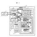
図1は、本発明の第一の実施形態に係る記憶装置システムを構成する記憶制御装置が一台の場合の構成図である。
図2は、本発明の第一の実施形態に係る記憶装置システムを構成する記憶制御装置が複数台の場合の構成図である。
【0029】
図1に示される記憶装置システムでは、記憶制御装置3が一台であり、それにホストコンピュータ1が接続されている。また、記憶制御装置3には、ディスク記憶装置4と保守端末5が接続されている。ディスク記憶装置4は、大容量のハードディスク装置で構成されている。保守端末5は、記憶制御装置3へ指示を与えたり、内部の状態を表示するための端末である。
【0030】
記憶制御装置3は、チャネルインタフェース31と、ディスクインタフェース35と、管理情報メモリ32と、キャッシュメモリ33とで構成されている。記憶制御装置3の各部位は、信頼性を向上させるために二重化されていて、各々の部位は、パスにより接続されている。
【0031】
チャネルインタフェース31は、ホストコンピュータ1と接続する部分である。ディスクインタフェース35は、ディスク記憶装置4と接続する部分である。管理情報メモリ32は、不揮発メモリであり、システムの制御に必要な管理情報が格納される。
【0032】
キャッシュメモリ33は、ホストコンピュータ1からディスク記憶装置4にアクセスするときの性能を向上させるために、データを一時的に格納するメモリである。
【0033】
チャネルインタフェース31は、一方の管理情報メモリ32が回復する際に、もう一方の正常な管理情報メモリ32から管理情報の内容をコピーする管理情報コピー処理341を備えている。ただし、この管理情報コピー処理341は、ディスクインタフェース35に置いても良い。
【0034】
管理情報メモリ32は、管理情報を格納する記憶制御装置内管理情報メモリモジュール321と、記憶制御装置内管理情報メモリモジュール321を制御する記憶制御装置内管理情報メモリコントローラ322から構成されている。
【0035】
記憶制御装置内管理情報メモリモジュール321は、記憶装置システム2の管理情報を格納するためのメモリモジュールである。
【0036】
また、記憶制御装置内管理情報メモリコントローラ322は、コントローラ動作状態342、管理情報メモリ状態344、コピー済み管理情報アドレス343を持っている。
【0037】
コントローラ動作状態342は、管理情報のリード/ライトを実行する際のアクセス先を管理するための情報である。管理情報メモリ状態344は、管理情報メモリ32の状態を示す情報である。コピー済み管理情報アドレス343は、管理情報コピー処理341が管理情報コピーの進捗を管理するために使用する。
【0038】
また、キャッシュメモリ33は、データを格納するキャッシュメモリモジュール331と、キャッシュメモリモジュール331を制御するキャッシュメモリコントローラ332から構成されている。
【0039】
図2に示される記憶装置システムでは、記憶制御装置3が複数台持っており、これは、図1の記憶装置システムをアップグレードしたものである。また、記憶制御装置3毎に、ディスク記憶装置4と保守端末3が接続されている。
【0040】
記憶制御装置3の構成と各部位の機能については、図1で示した例と同様である。また、各々の部位が二重化されていて、パスで接続されていることについても、図1に示した例と同様である。
【0041】
そして、この記憶制御装置3が複数台の構成では、記憶制御装置3の外部にキャッシュメモリスイッチ7と管理情報メモリスイッチ6を有していて、各記憶制御装置3のキャッシュメモリ33と管理情報メモリ32がスイッチング接続されている。
【0042】
キャッシュメモリスイッチ7は、内部にキャッシュメモリスイッチコントローラ71を持ち、記憶制御装置3のキャッシュメモリ33内のキャッシュメモリコントローラ332に接続されている。
【0043】
また、管理情報メモリスイッチ6は、内部に管理情報メモリスイッチコントラーラ61と、スイッチ内管理情報メモリモジュール62と、スイッチ内管理情報メモリコントローラ63から構成されていて、管理情報メモリスイッチコントラーラ61と、記憶制御装置内管理情報メモリコントローラ322と接続されている。
【0044】
スイッチ内管理情報メモリモジュール62は、管理情報を格納するためのメモリモジュールである。
【0045】
スイッチ内管理情報メモリコントローラ63は、スイッチ内管理情報メモリモジュール62を制御する部分であり、内部に管理情報メモリ状態345を有している。管理情報メモリ状態345は、スイッチ内に置かれる管理情報の状態を示す情報であり、各記憶制御装置3の記憶制御装置内管理情報メモリコントローラ322の管理情報メモリ状態344と、その状態値が常に一致されるように管理される。
【0046】
また、管理情報メモリ32、キャッシュメモリ33は、それぞれ二重化されているため、それらを接続するための管理情報メモリスイッチ6、キャッシュメモリスイッチ7も、それぞれ2台必要となる。
【0047】
記憶装置システム2の構成と管理情報の実装部位の関係は、以下のようにする。
【0048】
すなわち、記憶装置システム2を構成する記憶制御装置3が一台の場合には、管理情報を、図1に示される当該記憶制御装置3の管理情報メモリ32内の記憶制御装置内管理情報メモリモジュール321に格納する。これは、記憶制御装置3が一台の場合には、管理情報メモリスイッチ6、キャッシュメモリスイッチ7が不要であるため、これらを実装しないことで記憶装置システムのコストを削減するためである。
【0049】
一方、記憶装置システム2を構成する記憶制御装置3が複数台である場合には、図2に示される管理情報メモリスイッチ6のスイッチ内管理情報メモリモジュール62に格納する。これは、管理情報へのアクセス性能を確保するためである。この場合、各記憶制御装置3の記憶制御装置内管理情報メモリモジュール321は不要である。
(II)記憶装置システムの構成変更の手順
次に、図3および図4を用いて本実施形態に係る記憶装置システムの構成変更の手順を具体的に説明する。
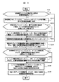
図3は、本発明の第一の実施形態に係る記憶装置システム2を構成する記憶制御装置3およびディスク記憶装置4を増設する際の手順を示すフローチャートである。
図4は、本発明の第一の実施形態に係る記憶装置システム2を構成する記憶制御装置3およびディスク記憶装置4を撤去する際の手順を示すフローチャートである。
【0050】
先ず、図3を用いて記憶装置システム2を構成する記憶制御装置3およびディスク記憶装置4を増設する際の手順について説明する。
【0051】
先ず、記憶装置システム2を構成する既存の記憶制御装置3が一台であるか否かを判断する(S301)。
【0052】
一台でない場合には、S306へ行く。
【0053】
一台である場合には、管理情報メモリスイッチ6とキャッシュメモリスイッチ7を用意し、既存の記憶制御装置3と接続する(S302)。この場合には、これらのスイッチを新設する必要があるからである。
【0054】
次に、管理情報メモリスイッチ6のスイッチ内管理情報メモリモジュール62に、既存の記憶制御装置3の記憶制御装置内管理情報メモリモジュール321に格納している管理情報を格納するのに必要なメモリ容量があるか判断する(S303)。
【0055】
必要なメモリ容量がある場合、S305へ行く。
【0056】
必要なメモリ容量がない場合、スイッチ内管理情報メモリモジュール62を、記憶制御装置内管理情報メモリモジュール321に格納している管理情報を格納するのに十分な容量まで増設する(S304)。
【0057】
次に、管理情報を記憶制御装置3の記憶制御装置内管理情報メモリモジュール321から管理情報メモリスイッチ6のスイッチ内管理情報メモリモジュール62へコピーする(S305)。コピー手順については、後に図5および図6を用いて詳述する。
【0058】
次に、増設するディスク記憶装置4を増設する記憶制御装置3に接続し、増設する記憶制御装置3を、管理情報メモリスイッチ6とキャッシュメモリスイッチ7に接続する(S306)。
【0059】
次に、管理情報メモリスイッチ6のスイッチ内管理情報メモリモジュール62に、ディスク記憶装置4と記憶制御装置3を増設するのに必要なメモリ容量があるか判断する(S307)。
【0060】
必要なメモリ容量がある場合には、S309へ行く。
【0061】
必要なメモリ容量がない場合には、スイッチ内管理情報メモリモジュール62を、ディスク記憶装置4と記憶制御装置3を増設するのに十分な容量まで増設する(S308)。
【0062】
次に、スイッチ内管理情報メモリモジュール62において、増設するディスク記憶装置4、および、増設する記憶制御装置3を使用するための管理情報を展開する(S309)。当該手順は、従来の記憶制御装置システムにおけるディスク記憶装置、チャネルインタフェース、ディスクインタフェースの追加と同様に実行される。
【0063】
最後に、増設したディスク記憶装置4、および、増設した記憶制御装置3の使用を開始する(S310)。
【0064】
次に、図4を用いて記憶装置システム2を構成する記憶制御装置3およびディスク記憶装置4を撤去する際の手順について説明する。
【0065】
先ず、撤去するディスク記憶装置4、および、撤去する記憶制御装置3の使用を中止する(S401)。
【0066】
次に、スイッチ内管理情報メモリモジュール62において、撤去するディスク記憶装置4、および、撤去する記憶制御装置3の使用に必要であった管理情報を削除する(S402)。当該手順は、従来の記憶制御装置システムにおける、記憶装置、チャネルインタフェース、ディスクインタフェースの削除と同様に実行される。
【0067】
次に、管理情報メモリスイッチ6のスイッチ内管理情報メモリモジュール62に、ディスク記憶装置4と記憶制御装置3を撤去することにより、減少するメモリ容量があるか判断する(S403)。
【0068】
減少するメモリ容量がない場合には、S405へ行く。
【0069】
減少するメモリ容量がある場合には、スイッチ内管理情報メモリモジュール62を、ディスク記憶装置4と記憶制御装置3の撤去したことにより減少する容量分だけ撤去する(S404)。
【0070】
次に、撤去する記憶制御装置3と、管理情報メモリスイッチ6、および、キャッシュメモリスイッチ7との接続を解除する(S405)。
【0071】
次に、撤去の結果、記憶装置システム2を構成する記憶制御装置3が一台となるか判断する(S406)。
【0072】
一台とならない場合には、撤去手順は終了である。
【0073】
一台となる場合には、システムに残す記憶制御装置3の記憶制御装置内管理情報メモリモジュール321に、既存の管理情報メモリスイッチ6のスイッチ内管理情報メモリモジュール62に格納している管理情報を格納するのに必要なメモリ容量があるか判断する(S407)。この場合は、管理情報を管理情報メモリスイッチ6から記憶制御装置内の管理情報メモリ32に移すからである。
【0074】
必要なメモリ容量がある場合、S409へ行く。
【0075】
必要なメモリ容量がない場合、記憶制御装置内管理情報メモリモジュール321を、スイッチ内管理情報メモリモジュール62に格納している管理情報を格納するのに十分な容量まで増設する(S408)。
【0076】
次に、管理情報を管理情報メモリスイッチ6のスイッチ内管理情報メモリモジュール62からシステムに残す記憶制御装置3の記憶制御装置内管理情報メモリモジュール321へコピーする(S409)。コピー手順については、後に図5および図6を用いて詳述する。
【0077】
最後に、システムに残す記憶制御装置3と、管理情報メモリスイッチ6、および、キャッシュメモリスイッチ7との接続を解除する(S410)。
(III)管理情報のコピー処理、管理情報へのアクセス処理詳細
次に、図5ないし図7を用いて管理情報のコピー処理と管理情報へのアクセス処理の詳細な手順について説明する。
図5は、記憶装置システム2を構成する記憶制御装置3およびディスク記憶装置4を増設/撤去する際に、管理情報をコピーする手順を示すフローチャートである。
図6は、チャネルインタフェース31において実行する管理情報コピー処理341を示すフローチャートである。
図7は、管理情報コピー処理341以外のチャネルインタフェース31、および、ディスクインタフェース35にからの管理情報へのアクセス手順を示すフローチャートである。
【0078】
ここで、管理情報に関する手順の詳細を説明する前に、予備概念と注意する点について説明する。
【0079】
本実施形態では、信頼性を確保するために、記憶制御装置3内の各部位、チャネルインタフェース31と、ディスクインタフェース35と、管理情報メモリ32と、キャッシュメモリ33とは、全て二重化されている。また、キャッシュメモリスイッチ6、管理情報メモリスイッチ7もそれに対応して二重化されている。
【0080】
したがって、管理情報のコピー処理については、それらの各々についてしなければならないと言うことと、二重化されているため、管理情報の一方が参照できない場合であっても、他方の系を参照できるときには、その記憶制御装置3の動作を停止しなくても良いことに注意しておく。ただし、コピー中に管理情報を書きこむ処理が発生したときには、データの整合性について注意が必要である。
【0081】
次に、管理情報メモリ状態は、管理情報コピー処理とその他のアクセス処理を制御するためのものであり、「正常」、「閉塞」、「コピー中」の三種類の状態をもっている。「正常」とは、その管理情報メモリにある管理情報を参照して使用可能であることを意味する。「閉塞」とは、その管理情報メモリにある管理情報は、参照できない状態であることを意味する。「コピー中」とは、その管理情報メモリに管理情報をコピーしている状態であることを意味する。
【0082】
なお、本実施形態においては、簡単のため、すべての管理情報を二重化しているが、二重化していなくても、本発明の範囲を制限するものではない。参照/更新できなくても、記憶制御装置3の動作を停止しなくてよい管理情報については、管理情報コピー処理341の対象とする必要はなく、管理情報メモリ状態344、345が「閉塞」の場合には、参照/更新不可とし、管理情報メモリ状態344、345が「正常」となる前に再構成することで、管理情報メモリ状態344、345が「正常」の場合、参照/更新可となるように制御すれば良い。
【0083】
管理情報メモリ状態は、記憶制御装置3内の記憶制御装置内管理情報メモリコントローラ342と、管理情報メモリスイッチ6内のスイッチ内管理情報メモリコントローラの両者に持っているが、これは、系が同じときには、両者の値を一致させると言うルールを設けておく。
【0084】
次に、記憶制御装置3内の記憶制御装置内管理情報メモリコントローラ342内にあるコントローラ動作状態342は、この記憶制御装置3の各系が、アクセスする管理情報の場所を示すものであり、この値が「スイッチ内管理情報アクセス」のときには、管理情報メモリスイッチ6内にある管理情報をアクセスし、この値が「記憶制御装置内管理情報アクセス」のときには、記憶制御装置3内にある管理情報メモリスイッチ内にある管理情報をアクセスすることを意味している。
【0085】
管理情報のコピーをおこなうときには、先ず、保守端末5より、二重化されている一方の系の管理情報メモリ状態344、345を「閉塞」とする(S501)。このとき、記憶制御装置3と管理情報メモリスイッチ6の両方の管理情報メモリ状態344、345が「閉塞」となるに注意する。
【0086】
管理情報メモリ状態を「閉塞」とすることにより、チャネルインタフェース31、および、ディスクインタフェース35からの管理情報の参照/更新が抑止される。
【0087】
二重化された一方の系の管理情報メモリ状態344、345が「閉塞」である状態であっても、記憶装置システム2は、二重化したもう一方の系の記憶制御装置内管理情報メモリモジュール321、あるいは、スイッチ内管理情報メモリモジュール62に格納している管理情報を使用して動作を継続することができる。
【0088】
次に、管理情報のコピー方向が、記憶制御装置3から管理情報メモリスイッチ6の方向か否か判断する(S502)。
【0089】
管理情報のコピー方向が、記憶制御装置3から管理情報メモリスイッチ6のときは、記憶制御装置3を一台から複数台に増やして、管理情報メモリスイッチ6を増設するときである。逆に、管理情報のコピー方向が、管理情報メモリスイッチ6から記憶制御装置3のときは、記憶制御装置3を複数台から一台に減らして、管理情報メモリスイッチ6を撤去するときである。
【0090】
管理情報のコピー方向が、記憶制御装置3から管理情報メモリスイッチ6の方向の場合には、保守端末5より、閉塞した方の記憶制御装置内管理情報メモリモジュール321、または、スイッチ内管理情報メモリモジュール62を参照/更新する際に使用する記憶制御装置内管理情報メモリコントローラ322のコントローラ動作状態342を、「記憶制御装置内管理情報アクセス」から「スイッチ内管理情報アクセス」に変更する(S503)。これにより、記憶制御装置内管理情報メモリコントローラ322は、以降の管理情報へのアクセス要求をスイッチ内の管理情報に対して実行するようになる。
【0091】
逆に、管理情報のコピー方向が、管理情報メモリスイッチ6から記憶制御装置3の方向の場合、保守端末5より、閉塞した方の記憶制御装置内管理情報メモリモジュール321、または、スイッチ内管理情報メモリモジュール62を参照/更新する際に使用する記憶制御装置内管理情報メモリコントローラ322のコントローラ動作状態342を、「スイッチ内管理情報アクセス」から「記憶制御装置内管理情報アクセス」に変更する(S504)。これにより、記憶制御装置内管理情報メモリコントローラ322は、以降の管理情報へのアクセス要求を記憶制御装置内の管理情報に対して実行するようになる。
【0092】
次に、保守端末5より、閉塞した管理情報メモリ状態344、345をコピー中とし、管理情報コピー処理341を起動する(S505)。管理情報コピー処理341の詳細については、次に、図6を用いて説明する。
【0093】
次に、管理情報コピー処理341が終了するのを待つ(S506)。
【0094】
次に、保守端末5より、コピー中とした管理情報メモリ状態344、345が正常となっていることを確認する(S507)。
【0095】
この時点で、管理情報は、二重化された一方の系の記憶制御装置内管理情報メモリモジュール321に、二重化されたもう一方の系のスイッチ内管理情報メモリモジュール62に格納した状態で二重化されていることになる。
【0096】
次に、二重化されたもう一方の系の管理情報メモリ状態344、345を「閉塞」とし(S508)、これまでと同様の処理を実行することで(S509〜S514)、最終的に、管理情報を、記憶制御装置内管理情報メモリモジュール321に二重化した状態から、スイッチ内管理情報メモリモジュール62に二重化した状態へ、または、スイッチ内管理情報メモリモジュール62に二重化した状態から、記憶制御装置内管理情報メモリモジュール321に二重化した状態へ移行させる。
【0097】
次に、図6を用いて管理情報コピー処理341の詳細手順について説明する。
【0098】
管理情報コピー処理341は、図5のS505,S512で呼ばれている処理であるが、これ以外にも、管理情報メモリ32を回復する類似のケースにも用いることができる。
【0099】
管理情報コピー処理341では、先ず、コピー済み管理情報アドレス343を管理情報コピー先の先頭に設定する(S601)。
【0100】
次に、コピー済み管理情報アドレス343が管理情報コピー先の終端であるか判断する(S602)。
【0101】
終端である場合、コピー中である管理情報メモリ状態344、345を正常とし(S606)、管理情報コピー処理341を終了する。
【0102】
終端でない場合、コピー元となる管理情報メモリ状態344が正常である側の、記憶制御装置内管理情報メモリモジュール321、または、スイッチ内管理情報メモリモジュール62から管理情報を一定量読み出し、コピー先となる管理情報メモリ状態344がコピー中である側の、スイッチ内管理情報メモリモジュール62、または、記憶制御装置内管理情報メモリモジュール321に書き込む(S603)。
【0103】
次に、コピー済み管理情報アドレス343をコピーした管理情報の量だけ加算する(S604)。
【0104】
そして、次に、管理情報コピー処理341実行中のホストからのリード/ライト要求に対する処理性能の低下を軽減するため、管理情報コピー処理341を一定時間中断させる(S605)。そして、一定時間経過後、S602へ戻る。
【0105】
次に、図7を用いてチャネルインタフェース31、および、ディスクインタフェース35における管理情報コピー処理341以外の管理情報へのアクセス手順を説明する。
【0106】
この処理においては、管理情報をライトする際に、コピー中のデータの整合性が失われないようにすることが重要である。
【0107】
先ず、二重化された両方の系の管理情報メモリ状態344を参照して(S701)、両方の系の管理情報メモリ状態344が正常であるか判断する(S702)。
【0108】
その際、記憶制御装置内管理情報メモリコントローラ322のコントローラ動作状態342によって、記憶制御装置内管理情報メモリモジュール321をアクセスするか、スイッチ内管理情報メモリモジュール62をアクセスするかが決まることに注意する。
【0109】
両方の系の管理情報メモリ状態344、345が正常であった場合、両方の系の管理情報に対してアクセスする(S703)。
【0110】
一方の管理情報メモリ状態344が正常でない場合、正常でない方の管理情報メモリ状態344が「コピー中」であるか判断する(S704)。
【0111】
「コピー中」でない場合、管理情報メモリ状態344が正常の管理情報に対してアクセスする(S705)。
【0112】
「コピー中」である場合、コピー済み管理情報アドレス343を参照し(S706)、アクセス要求がライト、かつ、アクセス先アドレスがコピー済み管理情報アドレス343より先頭側か判断する(S707)。
【0113】
条件不成立の場合、S705へ行く。この場合には、データのリードの場合か、データのライトであっても、コピー元にデータをライトするのみで良い。
【0114】
条件成立の場合には、両方の管理情報に対してライトを実行する(S708)。これは、管理情報コピー処理341終了時における二重化した管理情報の同一性を保つためである。すなわち、このときのライトは、コピー先にもおこなう。この「コピー中」の管理情報に対して実行したライトは、コントローラ動作状態342のに設定された値に従って、コピー先に対して実行されることになる。
(IV)管理情報のコピー処理のデータの流れと処理の概要
次に、図8および図9を用いて本実施形態に係る管理情報のコピー処理のデータの流れと処理の概要について説明する。
図8は、本発明の第一の実施形態に係る管理情報のコピー処理のデータの流れと処理の概要を示す模式図であって、管理情報を記憶制御装置3の記憶制御装置内管理情報メモリモジュール321から、管理情報メモリスイッチ6内のスイッチ内管理情報メモリモジュール6にコピーするときの図である。
図9は、本発明の第一の実施形態に係る管理情報のコピー処理のデータの流れと処理の概要を示す模式図であって、管理情報を管理情報メモリスイッチ6内のスイッチ内管理情報メモリモジュール6から記憶制御装置3の記憶制御装置内管理情報メモリモジュール321にコピーするときの図である。
【0115】
図8に示されているのは、管理情報を記憶制御装置3の記憶制御装置内管理情報メモリモジュール321から、管理情報メモリスイッチ6内のスイッチ内管理情報メモリモジュール62にコピーするときであり、記憶制御装置3が一台から複数台に新たに増設したときであって、管理情報メモリスイッチ6を増設したときにおこなう動作である。
【0116】
この記憶制御装置の各部位は、二重化されているため、これを図8ではA系、B系として表すことにする。そして、上段に書かれているのが、記憶制御装置3であり、下段にあるのが管理情報メモリスイッチ6である。そして、記憶制御装置3には、記憶制御装置内管理情報メモリモジュール321が置かれていて、管理情報メモリスイッチ6には、スイッチ内管理情報メモリモジュール62が置かれている。そして、その横に書いてあるのが、管理情報メモリ状態であり、ボックスの外側に書かれているのが、それぞれのコントローラ動作状態の値である。
【0117】
図8は、データの流れと処理の概要を示す図なので余計な構成物は、記述していない。また、以下で、記憶制御装置3の記憶制御装置内管理情報メモリモジュール321に管理情報があることを、単に「記憶制御装置3に管理情報がある。」と表現し、管理情報メモリスイッチ6内のスイッチ内管理情報メモリモジュール62に管理情報があることを、単に「管理情報メモリスイッチ6に管理情報がある。」と表現することにする。
【0118】
先ず、最初の状態の図8(a)では、A系、B系の管理情報は、共に記憶制御装置3内にあり、管理情報メモリ状態は、共に「正常」である。管理情報メモリ状態は、系統が同じ記憶制御装置3のものと、管理情報メモリスイッチ6とは、常に一致している。そして、コントローラ動作状態は、「記憶装置内管理情報アクセス」である。この状態では、記憶制御装置3は、記憶制御装置3内にある管理情報をアクセスして動作している。
【0119】
コピーしようとするときには、図8(b)に示されるように、先ず、A系の管理情報メモリ状態を、「閉塞」にする(図5のS501)。これにより、A系の管理情報は、記憶制御装置3により使われなくなる。
【0120】
次に、A系のコントローラ動作状態を、「スイッチ内管理情報アクセス」に変更し(図5のS503)、A系の管理情報メモリ状態を、「コピー中」にし、コピー処理を開始する(図5のS505)。コピー元は、B系のコントローラ動作状態が「記憶装置内管理情報アクセス」で、B系の管理情報メモリ状態が「正常」なので、B系の記憶制御装置3である。コピー先は、A系のコントローラ動作状態が「スイッチ内管理情報アクセス」で、A系の管理情報メモリ状態が「コピー中」なので、A系の管理情報メモリスイッチ6である(図6のS603)。
【0121】
コピーが終了すると、図8(c)に示されるように、A系の管理情報メモリ状態を「正常」にし(図6のS606)、B系の管理情報メモリ状態を「閉塞」にする(図5のS508)。そして、次に、B系のコントローラ動作状態を、「スイッチ内管理情報アクセス」に変更し(図5のS510)、B系の管理情報メモリ状態を、「コピー中」にし、再び、コピー処理を開始する(図5のS512)。コピー元は、A系のコントローラ動作状態が「スイッチ内管理情報アクセス」で、A系の管理情報メモリ状態が「正常」なので、A系の管理情報メモリスイッチ6である。コピー先は、B系のコントローラ動作状態が「スイッチ内管理情報アクセス」で、B系の管理情報メモリ状態が「コピー中」なので、B系の管理情報メモリスイッチ6である(図6のS603)。
【0122】
二度目のコピー処理が終了すると、図8(d)に示されるように、B系の管理情報メモリ状態を「正常」にする(図6のS606)。この図8(d)に示される状態になると、記憶制御装置3は、二重化された状態で、管理情報メモリスイッチ6内にある管理情報をアクセスして動作することができる。
【0123】
次に、図9に示されているのは、管理情報を管理情報メモリスイッチ6内のスイッチ内管理情報メモリモジュール62から、記憶制御装置3の記憶制御装置内管理情報メモリモジュール321にコピーするときであり、記憶制御装置3が複数台から一台にしたときであって、管理情報メモリスイッチ6を撤去するときにおこなう動作である。
【0124】
先ず、最初の状態の図9(a)では、A系、B系の管理情報は、共に管理情報メモリスイッチ6内にあり、管理情報メモリ状態は、共に「正常」である。管理情報メモリ状態は、系統が同じ記憶制御装置3のものと、管理情報メモリスイッチ6とは、常に一致しているのは前述の例と同様である。そして、コントローラ動作状態は、「スイッチ内管理情報アクセス」である。この状態では、記憶制御装置3は、管理情報メモリスイッチ6内にある管理情報をアクセスして動作している。
【0125】
コピーしようとするときには、図9(b)に示されるように、先ず、A系の管理情報メモリ状態を、「閉塞」にする(図5のS501)。これにより、A系の管理情報は、記憶制御装置3により使われなくなる。
【0126】
次に、A系のコントローラ動作状態を、「記憶制御装置内管理情報アクセス」に変更し(図5のS504)、A系の管理情報メモリ状態を、「コピー中」にし、コピー処理を開始する(図5のS505)。コピー元は、B系のコントローラ動作状態が「スイッチ内管理情報アクセス」で、B系の管理情報メモリ状態が「正常」なので、B系の管理情報メモリスイッチ6である。コピー先は、A系のコントローラ動作状態が「記憶制御装置内管理情報アクセス」で、A系の管理情報メモリ状態が「コピー中」なので、A系の記憶制御装置3である(図6のS603)。
【0127】
コピーが終了すると、図9(c)に示されるように、A系の管理情報メモリ状態を「正常」にし(図6のS606)、B系の管理情報メモリ状態を「閉塞」にする(図5のS508)。そして、次に、B系のコントローラ動作状態を、「記憶制御装置内管理情報アクセス」に変更し(図5のS511)、B系の管理情報メモリ状態を、「コピー中」にし、再び、コピー処理を開始する(図5のS512)。コピー元は、A系のコントローラ動作状態が「記憶制御装置内管理情報アクセス」で、A系の管理情報メモリ状態が「正常」なので、A系の記憶制御装置3である。コピー先は、B系のコントローラ動作状態が「記憶制御装置内管理情報アクセス」で、B系の管理情報メモリ状態が「コピー中」なので、B系の記憶制御装置3である(図6のS603)。
【0128】
二度目のコピー処理が終了すると、図9(d)に示されるように、B系の管理情報メモリ状態を「正常」にする(図6のS606)。この図9(d)に示される状態になると、記憶制御装置3は、二重化された状態で、記憶制御装置3内にある管理情報をアクセスして動作することができる。
【0129】
〔実施形態2〕
以下、本発明に係る第二の実施形態を、図10ないし図14を用いて説明する。
【0130】
本実施形態では、第一の実施形態と重複する所の説明は省略し、その技術的な差異を中心にして説明することにする。
(I)記憶装置システムの構成
先ず、図10および図11を用いて本発明の第二の実施形態に係る記憶装置システムの構成について説明する。
図10は、本発明の第二の実施形態に係る記憶装置システムを構成する記憶制御装置が一台の場合の構成図である。
図11は、本発明の第二の実施形態に係る記憶装置システムを構成する記憶制御装置が複数台の場合の構成図である。
【0131】
本発明の第一の実施形態においては、記憶装置システム2の管理情報を記憶制御装置3と管理情報メモリスイッチ6間でコピーする際に、記憶制御装置3の各部位が二重化されていることが前提で、一方の系の管理情報を閉塞して、コピー処理をするものであった。すなわち、コピー中にも、記憶装置システムが停止させず運用するためには、記憶制御装置3の各部位が二重化されている言う冗長性が必須のものであった。
【0132】
本実施形態は、必ずしも記憶制御装置3の各部位の二重化を前提としなくても、コピー中にも、記憶装置システムが停止せず稼動できるようにするものである。
【0133】
図10に示されるように本実施形態の記憶制御装置が一台の記憶装置システムにおいて、図1に示される第一の実施形態の構成との違いは、管理情報コピー処理346が、チャネルインタフェース31から記憶制御装置内管理情報メモリコントローラ323に移動したこと、管理情報メモリ状態344の代わりに、管理情報コピー情報347を設けた点である。管理情報コピー情報347は、コピーの方向と、その動作状態を示す情報であり、「記憶装置システム→管理情報メモリスイッチ:コピー中」と「管理情報メモリスイッチ→記憶装置システム:コピー中」、クリア値の三種類の値を持つ。クリア値のときには、コピーをおこなっていないことを意味する。
【0134】
図11に示されるように本実施形態の記憶制御装置が複数台の記憶装置システムにおいて、図2に示される第一の実施形態の構成との違いは、記憶制御装置内管理情報メモリコントローラ323に管理情報コピー処理346と、管理情報コピー情報347を持つ点、また、管理情報メモリスイッチ6内に管理情報コピー情報348を持つ点である。管理情報コピー情報348は、管理情報コピー情報347と常に同じ値が設定される。
【0135】
なお、図10および図11の例では、第一の実施形態と同様に、記憶制御装置3の各部位は、二重化されて記述されているが、コピー処理をおこなうためには、必ずしも二重化されている必要はない。
(II)記憶装置システムの構成変更の手順
本実施形態の記憶装置システムの構成変更の手順については、第一の実施形態で、図3および図4を用いて説明したものと同様である。
【0136】
すなわち、記憶装置システム2を構成する記憶制御装置3およびディスク記憶装置4を増設する際の手順については、図3により、また、記憶装置システム2を構成する記憶制御装置3およびディスク記憶装置4を増設する際の手順については、図4により説明される。
(III)管理情報のコピー処理、管理情報へのアクセス処理詳細
次に、図12ないし図14を用いて管理情報のコピー処理と管理情報へのアクセス処理の詳細な手順について説明する。
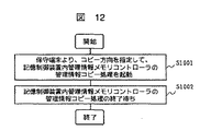
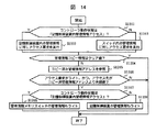
図12は、記憶装置システム2を構成する記憶制御装置3およびディスク記憶装置4を増設/撤去する際に、管理情報をコピーする手順を示すフローチャートである。
図13は、記憶制御装置3内において実行する管理情報コピー処理346を示すフローチャートである。
図14は、管理情報コピー処理346以外のチャネルインタフェース31、および、ディスクインタフェース35からの管理情報へのアクセス手順を示すフローチャートである。
【0137】
先ず、管理情報をコピーする際には、図12に示されるように、保守端末5から、記憶制御装置内管理情報メモリコントローラ323に、コピー方向を指定して、管理情報コピー処理346を起動する(S1001)。すなわち、管理情報メモリスイッチ6を増設するさいには、記憶制御装置3から管理情報メモリスイッチ6にコピーし、管理情報メモリスイッチ6を撤去するさいには、管理情報メモリスイッチ6から記憶制御装置3にコピーするように指定する。
【0138】
そして、記憶制御装置内管理情報メモリコントローラ323の管理情報コピー処理346の終了を待つ(S1002)。
【0139】
次に、図13を用いて管理情報コピー処理346について説明する。
【0140】
先ず、コピー済み管理情報アドレス343を管理情報コピー先の先頭に設定する(S1101)。
【0141】
次に、管理情報のコピー方向が、記憶制御装置3から管理情報メモリスイッチ6の方向かどうか判断する(S1102)。
【0142】
管理情報のコピー方向が、記憶制御装置3から管理情報メモリスイッチ6の方向の場合には、管理情報メモリスイッチ6の管理情報コピー情報348を「記憶制御装置→管理情報スイッチ:コピー中」に設定し(S1103)、さらに、記憶制御装置3の管理情報コピー情報347を、同様に、「記憶制御装置→管理情報スイッチ:コピー中」に設定する(S1104)。
【0143】
逆に、管理情報のコピー方向が、管理情報メモリスイッチ6から記憶制御装置3の方向の場合には、管理情報メモリスイッチ6の管理情報コピー情報348を「管理情報スイッチ→記憶制御装置:コピー中」に設定し(S1105)、さらに、記憶制御装置3の管理情報コピー情報347を、同様に、「管理情報スイッチ→記憶制御装置:コピー中」に設定する(S1106)。
【0144】
次に、コピー済み管理情報アドレス343が管理情報コピー先の終端であるか判断する(S1107)。
【0145】
終端である場合には、S1111へ行く。
【0146】
終端でない場合には、コピー元となる記憶制御装置内管理情報メモリモジュール321、または、スイッチ内管理情報メモリモジュール62から管理情報を一定量読み出し、コピー先となる、スイッチ内管理情報メモリモジュール62、または、記憶制御装置内管理情報メモリモジュール321に書き込む(S1108)。
【0147】
次に、コピー済み管理情報アドレス343をコピーした管理情報の量だけ加算する(S1109)。
【0148】
次に、チャネルインタフェース31、および、ディスクインタフェース35からのアクセス要求を長時間待たせないようにするため、管理情報コピー処理346を一定時間中断させる(S1110)。一定時間経過後、S1107へ行く。
【0149】
コピーが終了したときには、記憶制御装置3の管理情報コピー情報347をクリアする(S1111)。さらに、管理情報メモリスイッチ6の管理情報コピー情報348をクリアする(S1112)。
【0150】
次に、再び、管理情報のコピー方向が、記憶制御装置3から管理情報メモリスイッチ6の方向かどうか判断する(S1113)。
【0151】
管理情報のコピー方向が、記憶制御装置3から管理情報メモリスイッチ6の方向の場合には、コントローラ動作状態342を「記憶制御装置内管理情報アクセス」から「スイッチ内管理情報アクセス」に変更する(S1114)。
【0152】
管理情報のコピー方向が、管理情報メモリスイッチ6から記憶制御装置3の方向の場合には、コントローラ動作状態342を「スイッチ内管理情報アクセス」から「記憶制御装置内管理情報アクセス」に変更する(S1115)。
【0153】
コントローラ動作状態342は、管理情報のアクセスを、記憶制御装置3にあるものでおこなうのか、管理情報スイッチ6にあるものでおこなうのを示している。したがって、コピーが終った後の管理情報のアクセスは、常に、コピー先の方の管理情報におこなわれることになる。
【0154】
次に、図14を用いて管理情報コピー処理346以外のチャネルインタフェース31、および、ディスクインタフェース35からの管理情報へのアクセス手順を示すフローチャートである。
【0155】
先ず、コントローラ動作状態342が、「記憶制御装置内管理情報アクセス」であるか判断する(S1201)。
【0156】
コントローラ動作状態342が、「記憶制御装置内管理情報アクセス」である場合には、記憶制御装置内管理情報メモリモジュール321の管理情報に対しアクセス要求を実行する(S1202)。
コントローラ動作状態342が、「スイッチ内管理情報アクセス」である場合、管理情報メモリスイッチ6を介し、スイッチ内管理情報メモリモジュール62の管理情報に対しアクセス要求を実行する(S1203)。
【0157】
次に、管理情報コピー情報347がクリア値であるか判断する(S1204)。
【0158】
クリア値である場合、アクセス要求の処理を終了する。これは、管理情報コピー情報347がクリア値であるときには、コピー処理がおこなわれていないときであり、通常の処理のみで良いことを意味する。
【0159】
クリア値でない場合には、現在コピー中であることを意味している。この場合には、アクセス先は、コピー元になっている。そして、このときには、コピー済み管理情報アドレス343を参照し(S1205)、アクセス要求がライト、かつ、アクセス先アドレスがコピー済み管理情報アドレス343より先頭側か否かを判断する(S1206)。アクセス先アドレスがコピー済み管理情報アドレス343より先頭側にあるときには、コピーが既に終った領域へのアクセスであることを意味する。これは、コピー処理は、アドレスの先頭から後ろのアドレスに向かってするようにしているからである。
【0160】
条件不成立の場合には、アクセス要求の処理を終了する。この場合には、アクセス要求がリード要求であるか、ライト要求の場合であっても、コピーが未だ済んでいない領域の地点へのライト要求であることを意味している。この場合には、単に、コピー元にデータをライトすれば良い。
【0161】
条件成立の場合には、コントローラ動作状態342が、「記憶制御装置内管理情報アクセス」であるか判断する(S1207)。
【0162】
コントローラ動作状態342が、「記憶制御装置内管理情報アクセス」である場合、管理情報メモリスイッチ6を介し、スイッチ内管理情報メモリモジュール62の管理情報もライトする(S1208)。
【0163】
コントローラ動作状態342が、「スイッチ内管理情報アクセス」である場合、記憶制御装置内管理情報メモリモジュール321の管理情報もライトする(S1209)。
【0164】
すなわち、この条件が成立する場合には、ライトの時に、アクセス領域がコピーが済んだ領域なので、コピー先の方にもデータをライトしておいて、コピー処理が終了したときに管理情報の整合性が保たれるようにするためである。
【0165】
【発明の効果】
本発明によれば、記憶装置システムの構成を容易に変更可能であって、複数台の記憶装置システムのコンポーネントを結合し、一つの記憶装置システムとする場合であっても、記憶装置システムを論理的に単一の記憶装置システムとして管理して、管理情報の格納位置を、記憶装置システムの構成に応じて選択することにより、どのような構成であっても、管理情報を集中管理して、アクセス性能を低下させることのない記憶装置システムを提供することができる。
【0166】
また、本発明によれば、記憶装置システムの構成の変更時であっても、記憶装置システムの稼動を停止することなく、ホストからディスク記憶装置へのアクセスが可能な記憶装置システムの構成方法を提供することができる。
【図面の簡単な説明】
【図1】本発明の第一の実施形態に係る記憶装置システムを構成する記憶制御装置が一台の場合の構成図である。
【図2】本発明の第一の実施形態に係る記憶装置システムを構成する記憶制御装置が複数台の場合の構成図である。
【図3】本発明の第一の実施形態に係る記憶装置システム2を構成する記憶制御装置3およびディスク記憶装置4を増設する際の手順を示すフローチャートである。
【図4】本発明の第一の実施形態に係る記憶装置システム2を構成する記憶制御装置3およびディスク記憶装置4を撤去する際の手順を示すフローチャートである。
【図5】記憶装置システム2を構成する記憶制御装置3およびディスク記憶装置4を増設/撤去する際に、管理情報をコピーする手順を示すフローチャートである。
【図6】チャネルインタフェース31において実行する管理情報コピー処理341を示すフローチャートである。
【図7】管理情報コピー処理341以外のチャネルインタフェース31、および、ディスクインタフェース35にからの管理情報へのアクセス手順を示すフローチャートである。
【図8】本発明の第一の実施形態に係る管理情報のコピー処理のデータの流れと処理の概要を示す模式図であって、管理情報を記憶制御装置3の記憶制御装置内管理情報メモリモジュール321から、管理情報メモリスイッチ6内のスイッチ内管理情報メモリモジュール6にコピーするときの図である。
【図9】本発明の第一の実施形態に係る管理情報のコピー処理のデータの流れと処理の概要を示す模式図であって、管理情報を管理情報メモリスイッチ6内のスイッチ内管理情報メモリモジュール6から記憶制御装置3の記憶制御装置内管理情報メモリモジュール321にコピーするときの図である。
【図10】本発明の第二の実施形態に係る記憶装置システムを構成する記憶制御装置が一台の場合の構成図である。
【図11】本発明の第二の実施形態に係る記憶装置システムを構成する記憶制御装置が複数台の場合の構成図である。
【図12】記憶装置システム2を構成する記憶制御装置3およびディスク記憶装置4を増設/撤去する際に、管理情報をコピーする手順を示すフローチャートである。
【図13】記憶制御装置3内において実行する管理情報コピー処理346を示すフローチャートである。
【図14】管理情報コピー処理346以外のチャネルインタフェース31、および、ディスクインタフェース35からの管理情報へのアクセス手順を示すフローチャートである。
【符号の説明】
1…ホストコンピュータ
2…記憶装置システム
3…記憶制御装置
31…チャネルインタフェース
341、346…管理情報コピー処理
35…ディスクインタフェース
33…キャッシュメモリ
32…管理情報メモリ
321…記憶制御装置内管理情報メモリモジュール
322、323…記憶制御装置内管理情報メモリコントローラ
342…コントローラ動作状態
343…コピー済み管理情報アドレス
344、345…管理情報メモリ状態
347、348…管理情報コピー情報
4…ディスク記憶装置
5…保守端末
6…管理情報メモリスイッチ
62…スイッチ内管理情報メモリモジュール
63、64…スイッチ内管理情報メモリコントローラ
7…キャッシュメモリスイッチ[0001]
BACKGROUND OF THE INVENTION
The present invention relates to a storage device system and a storage device system configuration method, and can be operated without stopping the operation of the system when the storage control device changes the configuration from one to a plurality of devices. In either form, the present invention relates to a storage device system suitable for centrally managing system management information and a method for configuring the storage device system.
[0002]
[Prior art]
From large-scale storage systems required in data centers in companies to small-scale storage systems required in the general open market, the performance and storage capacity required for storage systems vary greatly depending on the application. Yes.
[0003]
To cope with the scalability problem required for this storage device system, conventionally, a storage computer system connected to the host computer is added, and the storage device systems are connected by a transfer path used for connection to the host computer. In such a case, a switch is connected between the storage system and the storage system.
[0004]
As another method of dealing with the scalability problem required for the storage device system, a method of combining components of a plurality of storage device systems and making the host computer appear to one storage device system can be considered. For example, there is a method in which a data transfer path and a management information transfer path in each storage device system are coupled to each other, and a plurality of storage device systems are combined into one storage device system.
[0005]
On the other hand, the conventional storage system control program assumes that the storage system to be controlled has a single storage system structure, both physically and logically. For this reason, in the case where a plurality of small storage device systems are combined to form a single storage device system, when the whole is not logically considered as a single storage device system, It is necessary to change the basic recognition, the change range extends to the entire control program, and the change scale becomes extremely large.
[0006]
For this reason, even when components of a plurality of storage device systems are combined to form a single storage device system, there is a demand to regard the structure of the storage device system as a logical single unit and divert the control program. is there.
[0007]
When the storage system structure is considered to be logically single, the storage system management information has consistency that cannot be divided for each component of the storage system, similar to conventional storage system management information. Information. For this reason, in order to store the management information, it is necessary to secure a logically continuous memory area as in the conventional storage device system.
[0008]
As a method of securing a memory area for storing management information, there is a method of using a management information memory distributed among components of each storage device system. However, managing the management information memory physically distributed as one logical makes it difficult to realize the maintenance function. This is because a conventional storage device system physically stores management information in a single management information memory.
[0009]
For example, if an arbitrary small storage system is removed from a state where multiple storage system components are combined and shown as a single storage system, the area that stores part of the management information is lost. It will be. The management information is consistent information that cannot be divided, and even if a part of the management information is lost, the whole becomes unusable. Therefore, it is necessary to stop the storage device system as it is.
[0010]
On the other hand, regarding the feasibility of the maintenance function by distributing the parts other than the management information memory storing the management information to each small storage device system, in the conventional storage device system, other than the management information memory Since the component has a partial blockage / maintenance / recovery function, the conventional method can be used relatively easily.
[0011]
[Problems to be solved by the invention]
In the conventional method of combining the components of a plurality of storage device systems to form one storage device system, the management method of the entire storage device system is not considered.
[0012]
For this reason, when trying to divert the control program of the conventional storage device system, there is a problem that the scale of change of the control program becomes extremely large and diversion becomes difficult.
[0013]
Further, in the conventional method of combining the components of a plurality of storage device systems into a single storage device system, when managing the storage device system logically as a single storage device system, each small storage device system It does not consider how to store management information of a storage system with consistency that cannot be divided into two.
[0014]
For this reason, the management information is stored in the management information memory of each physically distributed small storage system, making it difficult to realize the maintenance function. Further, there is a problem that the access performance deteriorates when the management information is physically distributed.
[0015]
Further, the conventional technology does not take into account that the storage device system can be flexibly adapted to the configuration change.
[0016]
This is because when a storage device system composed of a single component is changed to a component of a plurality of storage device systems, when the management information needs to be moved, the storage system is stopped. There is a problem that the disk storage device cannot be accessed from the host. In particular, this increases the scale of the system and becomes a big barrier such as version upgrade of a system that requires constant operation.
[0017]
The present invention has been made to solve the above-described problems, and an object of the present invention is to easily change the configuration of a storage device system, which combines components of a plurality of storage device systems to provide a single storage device. Even in the case of the device system, the storage device system is logically managed as a single storage device system, and the storage location of management information is selected according to the configuration of the storage device system. It is an object of the present invention to provide a storage system that centrally manages management information and does not degrade access performance even with a simple configuration.
[0018]
It is another object of the present invention to provide a method for configuring a storage device system that allows a host to access a disk storage device without stopping the operation of the storage device system even when the configuration of the storage device system is changed.
[0019]
[Means for Solving the Problems]
In order to achieve the above object, a configuration of an invention related to a storage device system of the present invention is a storage device system for accessing a disk storage device from a host computer. The storage device system includes a storage control device, a disk storage device, and the like. The storage control device has a channel interface connected to the host computer, a disk interface connected to the disk storage device, and a management information memory for storing management information of the storage device system. When there are a plurality of storage control devices, the management information memory included in them is connected by a management information memory switch having a management information memory module, and the storage control device is one. In the case, the management information memory is managed with a management information memory controller. Information management module, the management information memory comprises a management information memory controller, and the management information memory controller comprises a single storage control device. In some cases, the management information memory module in the storage control device is accessed, and when there are a plurality of storage control devices, the management information memory module in the management information memory switch is accessed. It is intended to work.
[0020]
More specifically, when the storage control device is one unit, the storage device system management information is stored in the management information memory module in the storage control unit, and the storage control unit includes a plurality of storage control units. In this case, the information is stored in the management information memory module in the management information memory switch.
[0021]
In order to achieve the above object, a configuration of a storage device system according to the present invention is a storage device system configuration method for accessing a disk storage device from a host computer. A storage device, a channel interface connected to the host computer, a disk interface connected to the disk storage device, and management information for the storage device system. When the storage control device is a single unit, the management information memory includes a management information memory controller and a management information memory module, and the storage control device includes a plurality of storage control devices. The management information memory from the management information memory controller Ri, connected by the management information memory switch said management information memory, in which then place a management information memory module in the management information memory switch.
[0022]
More specifically, in the configuration method of the storage device system, the storage device system management information is stored in the management information memory module in the storage control device when the storage control device is a single unit. When there are a plurality of storage control devices, they are stored in the management information memory module in the management information memory switch.
[0023]
In order to achieve the above object, in the configuration method of the storage device system of the present invention, the configuration of the invention in which a storage control device is added is that the management information includes a management information memory in the storage control device, and the management information memory Each switch is stored redundantly, and the management information memories in the multiple storage control devices are connected when the number of storage control devices constituting this system is increased from one to multiple. In each of the redundant management information systems, the management information memory and the management information memory switch are connected to each other, and one of the redundant management information systems is blocked. Copy the management information of the management information system that is not blocked to the management information memory switch of the management information system that is blocked, and then release the blocking information The management information storage location is changed from the management information memory in the storage control device to the management information memory switch by executing the above-mentioned procedure in order for each of the duplicated management information systems. In this storage system, the access to the disk storage device from the host computer during the change of the management information storage location is processed using the management information of the management information that is not blocked. Is.
[0024]
In order to achieve the above object, in the configuration method of the storage device system of the present invention, the configuration of the invention for removing the storage control device is that the management information includes a management information memory in the storage control device, and the management information memory. When the management information memory and the management information memory switch are connected to each other in each of the redundant management information systems, the system is stored in the switch. When removing the storage control devices constituting the system from a plurality of units, one of the redundant management information systems is blocked, and the management information of the management information system that is not blocked is blocked. The procedure of copying to the management information memory of the management information system and then releasing the blockage is executed in order for each of the redundant management information systems. As a result, the storage location of management information is changed from the management information memory switch to the management information memory in the storage control device, and the storage device system changes the storage location of the management information in the host computer. Is used to process access to the disk storage device from the management information of the management information that is not blocked.
[0025]
In order to achieve the above object, in the configuration method of the storage device system of the present invention, another configuration of the invention for adding a storage control device is to add a storage control device constituting this system from one to a plurality of units. A management information memory switch for connecting management information memories in the plurality of storage control devices, and connecting the management information memory in the storage control device and the management information memory switch to the management information memory. The stored management information is copied to the management information memory switch, and the storage location of the management information is changed from the management information memory in the storage control device to the management information memory switch. The device system stores the access from the host computer to the disk storage device during the change of the management information storage location as the copy source. It is obtained so as to process using the management information stored in the management information memory in the control device.
[0026]
In order to achieve the above object, in the configuration method of the storage device system of the present invention, another configuration of the invention for removing the storage control device is a management information memory switch for connecting management information memories in the plurality of storage control devices. When the storage control device constituting this system is removed from a plurality of units, the management information stored in the management information memory switch is stored in the storage control device. The management information storage location is changed from the management information memory switch to the management information memory in the storage control device, and the storage system stores the management information storage location. The management information stored in the management information memory switch that is the copy source is the access to the disk storage device from the host computer that is being changed. It is obtained as treatment with.
[0027]
DETAILED DESCRIPTION OF THE INVENTION
Embodiments according to the present invention will be described below with reference to FIGS.
[0028]
A first embodiment according to the present invention will be described below with reference to FIGS.
(I) Configuration of storage system
First, the configuration of the storage device system according to the first embodiment of the present invention will be described with reference to FIGS. 1 and 2.
FIG. 1 is a configuration diagram in the case where there is one storage control device configuring the storage device system according to the first embodiment of the present invention.
FIG. 2 is a configuration diagram in the case where there are a plurality of storage control devices constituting the storage device system according to the first embodiment of the present invention.
[0029]
In the storage device system shown in FIG. 1, there is one
[0030]
The
[0031]
The
[0032]
The
[0033]
The
[0034]
The
[0035]
The management
[0036]
Further, the storage control device management
[0037]
The
[0038]
The
[0039]
In the storage device system shown in FIG. 2, the
[0040]
The configuration of the
[0041]
When the
[0042]
The cache memory switch 7 has a cache
[0043]
The management
[0044]
The intra-switch management
[0045]
The intra-switch management
[0046]
Further, since the
[0047]
The relationship between the configuration of the
[0048]
That is, when there is one
[0049]
On the other hand, when there are a plurality of
(II) Procedure for changing the configuration of the storage system
Next, the procedure for changing the configuration of the storage system according to the present embodiment will be specifically described with reference to FIGS.
FIG. 3 is a flowchart showing a procedure for adding the
FIG. 4 is a flowchart showing a procedure for removing the
[0050]
First, the procedure for adding the
[0051]
First, it is determined whether or not the existing
[0052]
If not, go to S306.
[0053]
If there is one, the management
[0054]
Next, the memory capacity required for storing the management information stored in the storage control device management
[0055]
If there is a necessary memory capacity, go to S305.
[0056]
If the required memory capacity is not available, the in-switch management
[0057]
Next, the management information is copied from the in-storage management
[0058]
Next, the additional
[0059]
Next, it is determined whether the intra-switch management
[0060]
If there is a necessary memory capacity, go to S309.
[0061]
If the necessary memory capacity is not available, the in-switch management
[0062]
Next, management information for using the
[0063]
Finally, use of the added
[0064]
Next, a procedure for removing the
[0065]
First, use of the
[0066]
Next, in the in-switch management
[0067]
Next, it is determined whether the intra-switch management
[0068]
If there is no memory capacity to decrease, the process goes to S405.
[0069]
If there is a memory capacity to decrease, the in-switch management
[0070]
Next, the connection between the
[0071]
Next, as a result of the removal, it is determined whether there is one
[0072]
If not, the removal procedure is complete.
[0073]
In the case of a single unit, the management information stored in the in-switch management
[0074]
If there is a necessary memory capacity, go to S409.
[0075]
If the necessary memory capacity is not available, the storage control device management
[0076]
Next, the management information is copied from the intra-switch management
[0077]
Finally, the connection between the
(III) Management information copy processing and management information access processing details
Next, detailed procedures of management information copy processing and management information access processing will be described with reference to FIGS.
FIG. 5 is a flowchart showing a procedure for copying management information when the
FIG. 6 is a flowchart showing the management
FIG. 7 is a flowchart showing a procedure for accessing management information from the
[0078]
Here, before explaining the details of the procedure related to management information, a preliminary concept and points to be noted will be explained.
[0079]
In this embodiment, in order to ensure reliability, each part in the
[0080]
Therefore, the management information copy processing must be performed for each of them, and since it is duplicated, even when one of the management information cannot be referred to, when the other system can be referred to, Note that it is not necessary to stop the operation of the
[0081]
Next, the management information memory state is for controlling the management information copy process and other access processes, and has three types of states: “normal”, “blocked”, and “copying”. “Normal” means that it can be used with reference to the management information in the management information memory. “Blocked” means that the management information in the management information memory cannot be referred to. “Copying” means that the management information is being copied to the management information memory.
[0082]
In this embodiment, all management information is duplicated for simplicity, but the scope of the present invention is not limited even if it is not duplicated. Management information that does not need to stop the operation of the
[0083]
The management information memory state is possessed by both the management
[0084]
Next, the
[0085]
When copying the management information, first, the management information memory states 344 and 345 of one of the duplexed systems are set to “blocked” from the maintenance terminal 5 (S501). At this time, it should be noted that the management information memory states 344 and 345 of both the
[0086]
By setting the management information memory state to “blocked”, reference / update of management information from the
[0087]
Even if the management information memory states 344 and 345 of one of the duplexed systems are “blocked”, the
[0088]
Next, it is determined whether the copy direction of the management information is from the
[0089]
When the copy direction of the management information is from the
[0090]
When the copy direction of the management information is from the
[0091]
Conversely, when the copy direction of the management information is the direction from the management
[0092]
Next, the management information memory states 344 and 345 that have been blocked are set as being copied from the
[0093]
Next, the process waits for the management
[0094]
Next, it is confirmed from the
[0095]
At this point, the management information is duplicated in a state in which it is stored in the duplicated storage management device internal management
[0096]
Next, the management information memory states 344 and 345 of the other duplicated system are set to “blocked” (S508), and the same processing as before is executed (S509 to S514). Is managed in the storage controller management
[0097]
Next, a detailed procedure of the management
[0098]
The management
[0099]
In the management
[0100]
Next, it is determined whether the copied
[0101]
If it is the end, the management information memory states 344 and 345 being copied are made normal (S606), and the management
[0102]
If it is not the end, a certain amount of management information is read from the management
[0103]
Next, the copied
[0104]
Next, the management
[0105]
Next, an access procedure to management information other than the management
[0106]
In this processing, it is important that the consistency of data being copied is not lost when management information is written.
[0107]
First, the management information memory states 344 of both systems are referred to (S701), and it is determined whether the management information memory states 344 of both systems are normal (S702).
[0108]
At this time, it should be noted that the
[0109]
If the management information memory states 344 and 345 of both systems are normal, the management information of both systems is accessed (S703).
[0110]
If one management
[0111]
If it is not “copying”, the management
[0112]
If “copied”, the copied
[0113]
If the condition is not satisfied, go to S705. In this case, even when data is read or data is written, it is only necessary to write the data to the copy source.
[0114]
If the condition is satisfied, write is executed for both pieces of management information (S708). This is for maintaining the identity of the duplicated management information at the end of the management
(IV) Data flow and processing overview of management information copy processing
Next, the data flow of the management information copying process according to the present embodiment and the outline of the process will be described with reference to FIGS.
FIG. 8 is a schematic diagram showing the data flow of the management information copy process and the outline of the process according to the first embodiment of the present invention. The management information is stored in the storage control device management information memory of the
FIG. 9 is a schematic diagram showing the data flow and processing outline of the management information copy process according to the first embodiment of the present invention. The management information is stored in the management information memory in the switch in the management
[0115]
FIG. 8 shows a case where the management information is copied from the storage control device management
[0116]
Since each part of the storage control device is duplicated, this is represented as A system and B system in FIG. The
[0117]
Since FIG. 8 is a diagram showing an outline of the data flow and processing, unnecessary components are not described. In the following, the management information in the storage control device management
[0118]
First, in FIG. 8A in the initial state, both the A-system and B-system management information are in the
[0119]
When copying is attempted, as shown in FIG. 8B, first, the A-system management information memory state is set to “block” (S501 in FIG. 5). As a result, the A-system management information is not used by the
[0120]
Next, the controller operating state of the A system is changed to “in-switch management information access” (S503 in FIG. 5), the management information memory state of the A system is set to “copying”, and copy processing is started (FIG. 5). 5 S505). The copy source is the B-system
[0121]
When copying is completed, as shown in FIG. 8C, the A-system management information memory state is set to “normal” (S606 in FIG. 6), and the B-system management information memory state is set to “blocked” (FIG. 8). 5 S508). Then, the B system controller operating state is changed to “in-switch management information access” (S510 in FIG. 5), the B system management information memory state is set to “copying”, and the copy process is performed again. Start (S512 in FIG. 5). The copy source is the A-system management
[0122]
When the second copy process is completed, as shown in FIG. 8D, the B-system management information memory state is set to “normal” (S606 in FIG. 6). In the state shown in FIG. 8D, the
[0123]
Next, FIG. 9 shows when the management information is copied from the intra-switch management
[0124]
First, in FIG. 9A in the initial state, both the A-system and B-system management information are in the management
[0125]
When copying, as shown in FIG. 9B, first, the A-system management information memory state is set to “block” (S501 in FIG. 5). As a result, the A-system management information is not used by the
[0126]
Next, the A-system controller operation state is changed to “in-storage control device management information access” (S504 in FIG. 5), the A-system management information memory state is set to “copying”, and the copy process is started. (S505 in FIG. 5). The copy source is the B-system management
[0127]
When copying is completed, as shown in FIG. 9C, the A-system management information memory state is set to “normal” (S606 in FIG. 6), and the B-system management information memory state is set to “blocked” (FIG. 9). 5 S508). Next, the controller operation state of the B system is changed to “in-storage control device management information access” (S511 in FIG. 5), the management information memory state of the B system is changed to “copying”, and the copy is performed again. The process is started (S512 in FIG. 5). The copy source is the A-system
[0128]
When the second copy process is completed, as shown in FIG. 9D, the B-system management information memory state is set to “normal” (S606 in FIG. 6). In the state shown in FIG. 9D, the
[0129]
[Embodiment 2]
Hereinafter, a second embodiment according to the present invention will be described with reference to FIGS.
[0130]
In this embodiment, the description of the same part as the first embodiment is omitted, and the technical difference will be mainly described.
(I) Configuration of storage system
First, the configuration of the storage device system according to the second embodiment of the present invention will be described with reference to FIGS.
FIG. 10 is a configuration diagram in the case where one storage control device is included in the storage device system according to the second embodiment of the present invention.
FIG. 11 is a configuration diagram in the case where there are a plurality of storage control devices constituting the storage device system according to the second embodiment of the present invention.
[0131]
In the first embodiment of the present invention, when the management information of the
[0132]
In the present embodiment, the storage device system can be operated without being stopped even during copying, without necessarily assuming that each part of the
[0133]
As shown in FIG. 10, in a storage device system having one storage control device of this embodiment, the difference from the configuration of the first embodiment shown in FIG. The management information copy
[0134]
As shown in FIG. 11, in the storage device system having a plurality of storage control devices of this embodiment, the difference from the configuration of the first embodiment shown in FIG. The management
[0135]
In the examples of FIGS. 10 and 11, as in the first embodiment, each part of the
(II) Procedure for changing the configuration of the storage system
The procedure for changing the configuration of the storage system according to this embodiment is the same as that described with reference to FIGS. 3 and 4 in the first embodiment.
[0136]
That is, the procedure for adding the
(III) Management information copy processing and management information access processing details
Next, detailed procedures of management information copy processing and management information access processing will be described with reference to FIGS.
FIG. 12 is a flowchart showing a procedure for copying management information when adding / removing the
FIG. 13 is a flowchart showing management information copy processing 346 executed in the
FIG. 14 is a flowchart showing a procedure for accessing management information from the
[0137]
First, when copying the management information, as shown in FIG. 12, the management
[0138]
Then, it waits for the end of the management
[0139]
Next, the management
[0140]
First, the copied
[0141]
Next, it is determined whether the copy direction of the management information is from the
[0142]
When the copy direction of the management information is from the
[0143]
Conversely, when the copy direction of the management information is from the management
[0144]
Next, it is determined whether the copied
[0145]
If it is the end, go to S1111.
[0146]
If it is not the termination, a certain amount of management information is read from the management
[0147]
Next, the copied
[0148]
Next, the management
[0149]
When copying is completed, the management information copy
[0150]
Next, it is determined again whether or not the copy direction of the management information is from the
[0151]
When the copy direction of the management information is the direction from the
[0152]
When the copy direction of the management information is the direction from the management
[0153]
The
[0154]
Next, FIG. 14 is a flowchart showing a procedure for accessing management information from the
[0155]
First, it is determined whether or not the
[0156]
When the
When the
[0157]
Next, it is determined whether the management information copy
[0158]
If it is a clear value, the processing of the access request is terminated. This means that when the management information copy
[0159]
If it is not a clear value, it means that it is currently being copied. In this case, the access destination is the copy source. At this time, the copied
[0160]
If the condition is not satisfied, the access request processing is terminated. In this case, it means that even if the access request is a read request or a write request, it is a write request to a point in an area where copying has not yet been completed. In this case, data is simply written to the copy source.
[0161]
If the condition is satisfied, it is determined whether or not the
[0162]
If the
[0163]
When the
[0164]
In other words, if this condition is met, the access area is the area that has been copied at the time of writing, so the data is also written to the copy destination and the management information is consistent when the copying process is completed. This is to keep the sex.
[0165]
【The invention's effect】
According to the present invention, even when the configuration of a storage device system can be easily changed and components of a plurality of storage device systems are combined into a single storage device system, the storage device system is logically changed. By managing as a single storage device system and selecting the storage location of management information according to the configuration of the storage device system, the management information is centrally managed in any configuration, It is possible to provide a storage system that does not degrade the access performance.
[0166]
Further, according to the present invention, there is provided a storage device system configuration method capable of accessing a disk storage device from a host without stopping the operation of the storage device system even when the configuration of the storage device system is changed. Can be provided.
[Brief description of the drawings]
FIG. 1 is a configuration diagram in the case of a single storage control device configuring a storage device system according to a first embodiment of the present invention.
FIG. 2 is a configuration diagram in the case where a plurality of storage control devices are included in the storage device system according to the first embodiment of the present invention.
FIG. 3 is a flowchart showing a procedure for adding a
FIG. 4 is a flowchart showing a procedure for removing the
FIG. 5 is a flowchart showing a procedure for copying management information when adding / removing the
6 is a flowchart showing management information copy processing 341 executed in the
FIG. 7 is a flowchart showing a procedure for accessing management information from the
FIG. 8 is a schematic diagram showing the data flow of the management information copy process and the outline of the process according to the first embodiment of the present invention, wherein the management information is stored in the storage control device management information memory of the
FIG. 9 is a schematic diagram showing a data flow and an outline of processing of management information copy processing according to the first embodiment of the present invention, wherein the management information is stored in the management information memory in the switch in the management
FIG. 10 is a configuration diagram in the case where there is one storage control device configuring the storage device system according to the second embodiment of the present invention.
FIG. 11 is a configuration diagram in the case where a plurality of storage control devices are included in the storage device system according to the second embodiment of the present invention.
FIG. 12 is a flowchart showing a procedure for copying management information when adding / removing the
13 is a flowchart showing management information copy processing 346 executed in the
FIG. 14 is a flowchart illustrating a procedure for accessing management information from the
[Explanation of symbols]
1 ... Host computer
2 ... Storage device system
3. Storage control device
31 ... Channel interface
341, 346 ... management information copy processing
35 ... Disk interface
33 ... Cache memory
32 ... Management information memory
321 ... Management information memory module in the storage controller
322, 323 ... Management information memory controller in storage controller
342 ... Controller operating state
343 ... Copied management information address
344, 345 ... Management information memory state
347, 348 ... management information copy information
4. Disk storage device
5. Maintenance terminal
6 ... Management information memory switch
62 ... Management information memory module in switch
63, 64 ... Management information memory controller in the switch
7 ... Cache memory switch
Claims (2)
記憶制御装置と、
ディスク記憶装置とを備え、
前記記憶制御装置は、
前記ホストコンピュータと接続するチャネルインタフェースと、
前記ディスク記憶装置に接続するディスクインタフェースと、
この記憶装置システムの管理情報を格納するための管理情報メモリとを有し、
前記記憶制御装置が、一台である場合には、
前記管理情報メモリは、
管理情報メモリコントローラと、
管理情報メモリモジュールとを有し、
前記管理情報は、前記記憶制御装置内の管理情報メモリと、管理情報メモリスイッチとに、それぞれ二重化されて格納されるようになっていて、
前記記憶制御装置が、複数台である場合には、
前記管理情報メモリは、
管理情報メモリコントローラを有するようにし、
前記管理情報メモリを管理情報メモリスイッチにより接続して、
前記管理情報メモリスイッチに管理情報メモリモジュールを置くようにし、
この記憶装置システムの管理情報を、
前記管理情報メモリスイッチ内の前記管理情報メモリモジュールに格納し、
このシステムを構成する記憶制御装置を一台から複数台に増設する際に、
前記複数の記憶制御装置内の管理情報メモリを接続する管理情報メモリスイッチを追加し、
二重化された管理情報の系のそれぞれにおいて、前記管理情報メモリと、前記管理情報メモリスイッチとを接続し、
前記二重化された管理情報の系の一方を閉塞し、閉塞されていない管理情報の系の管理情報を、閉塞された管理情報の系の前記管理情報メモリスイッチにコピーして、その後に、閉塞を解除するという手順を、前記二重化された管理情報の系の各々について順に実行することにより、管理情報の格納位置を、前記記憶制御装置内の管理情報メモリ内から前記管理情報メモリスイッチ内に変更し、
しかも、この記憶装置システムは、管理情報の格納位置の変更中の前記ホストコンピュータからの前記ディスク記憶装置へのアクセスを、前記閉塞されていない管理情報の系の管理情報を用いて処理することを特徴とする記憶装置システムの構成方法。 In a method for configuring a storage device system for accessing a disk storage device from a host computer,
A storage controller;
A disk storage device,
The storage controller is
A channel interface connected to the host computer;
A disk interface connected to the disk storage device;
A management information memory for storing management information of the storage device system;
When the storage control device is one,
The management information memory is
A management information memory controller;
A management information memory module;
The management information is stored in a duplicated manner in the management information memory and the management information memory switch in the storage control device,
When there are a plurality of the storage control devices,
The management information memory is
Have a management information memory controller ,
The management information memory is connected by a management information memory switch,
A management information memory module is placed in the management information memory switch;
Management information of this storage device system
Storing in the management information memory module in the management information memory switch;
When expanding the storage control devices that make up this system from one to multiple units,
A management information memory switch for connecting management information memories in the plurality of storage control devices is added;
In each of the duplicated management information systems, the management information memory and the management information memory switch are connected,
Block one of the duplicated management information systems, copy the management information of the management information that is not blocked to the management information memory switch of the blocked management information system, and then close the blocking. The storage location of management information is changed from the management information memory in the storage control device to the management information memory switch by sequentially executing the release procedure for each of the redundant management information systems. ,
In addition, the storage device system processes the access to the disk storage device from the host computer during the change of the storage location of the management information using the management information of the management information that is not blocked. A method of configuring a storage device system.
記憶制御装置と、
ディスク記憶装置とを備え、
前記記憶制御装置は、
前記ホストコンピュータと接続するチャネルインタフェースと、
前記ディスク記憶装置に接続するディスクインタフェースと、
この記憶装置システムの管理情報を格納するための管理情報メモリとを有し、
前記記憶制御装置が、一台である場合には、
前記管理情報メモリは、
管理情報メモリコントローラと、
管理情報メモリモジュールとを有し、
前記記憶制御装置が、複数台である場合には、
前記管理情報メモリは、
管理情報メモリコントローラを有するようにし、
前記管理情報メモリを管理情報メモリスイッチにより接続して、
前記管理情報メモリスイッチに管理情報メモリモジュールを置くようにし、
この記憶装置システムの管理情報を、
前記管理情報メモリスイッチ内の前記管理情報メモリモジュールに格納し、
このシステムを構成する記憶制御装置を一台から複数台に増設する際に、
前記複数の記憶制御装置内の管理情報メモリを接続する管理情報メモリスイッチを追加し、
前記記憶制御装置内の管理情報メモリと、前記管理情報メモリスイッチとを接続し、
前記管理情報メモリに格納されている管理情報を、前記管理情報メモリスイッチにコピーして、管理情報の格納位置を、前記記憶制御装置内の管理情報メモリ内から前記管理情報メモリスイッチ内に変更し、
この記憶装置システムは、管理情報の格納位置の変更中の前記ホストコンピュータからの前記ディスク記憶装置へのアクセスを、コピー元である前記記憶制御装置内の管理情報メモリに格納された管理情報を用いて処理することを特徴とする記憶装置システムの構成方法。 In a method for configuring a storage device system for accessing a disk storage device from a host computer,
A storage controller;
A disk storage device,
The storage controller is
A channel interface connected to the host computer;
A disk interface connected to the disk storage device;
A management information memory for storing management information of the storage device system;
When the storage control device is one,
The management information memory is
A management information memory controller;
A management information memory module;
When there are a plurality of the storage control devices,
The management information memory is
Have a management information memory controller ,
The management information memory is connected by a management information memory switch,
A management information memory module is placed in the management information memory switch;
Management information of this storage device system
Storing in the management information memory module in the management information memory switch;
When expanding the storage control devices that make up this system from one to multiple units,
A management information memory switch for connecting management information memories in the plurality of storage control devices is added;
Connecting the management information memory in the storage control device and the management information memory switch;
The management information stored in the management information memory is copied to the management information memory switch, and the storage location of the management information is changed from the management information memory in the storage control device to the management information memory switch. ,
This storage system uses the management information stored in the management information memory in the storage control device that is the copy source for the access to the disk storage device from the host computer during the change of the management information storage location. And processing the storage device system.
Priority Applications (3)
| Application Number | Priority Date | Filing Date | Title |
|---|---|---|---|
| JP2001237439A JP4060552B2 (en) | 2001-08-06 | 2001-08-06 | Storage device system and storage device system configuration method |
| US09/945,671 US6757792B2 (en) | 2001-08-06 | 2001-09-05 | Storage system and method of configuring the storage system |
| US10/862,628 US7206905B2 (en) | 2001-08-06 | 2004-06-08 | Storage system and method of configuring the storage system |
Applications Claiming Priority (1)
| Application Number | Priority Date | Filing Date | Title |
|---|---|---|---|
| JP2001237439A JP4060552B2 (en) | 2001-08-06 | 2001-08-06 | Storage device system and storage device system configuration method |
Related Child Applications (1)
| Application Number | Title | Priority Date | Filing Date |
|---|---|---|---|
| JP2007286350A Division JP4825187B2 (en) | 2007-11-02 | 2007-11-02 | Storage device system and control method of storage device system |
Publications (2)
| Publication Number | Publication Date |
|---|---|
| JP2003050749A JP2003050749A (en) | 2003-02-21 |
| JP4060552B2 true JP4060552B2 (en) | 2008-03-12 |
Family
ID=19068523
Family Applications (1)
| Application Number | Title | Priority Date | Filing Date |
|---|---|---|---|
| JP2001237439A Expired - Fee Related JP4060552B2 (en) | 2001-08-06 | 2001-08-06 | Storage device system and storage device system configuration method |
Country Status (2)
| Country | Link |
|---|---|
| US (2) | US6757792B2 (en) |
| JP (1) | JP4060552B2 (en) |
Families Citing this family (27)
| Publication number | Priority date | Publication date | Assignee | Title |
|---|---|---|---|---|
| JP2001166993A (en) * | 1999-12-13 | 2001-06-22 | Hitachi Ltd | Storage control device and cache memory control method |
| JP4060552B2 (en) * | 2001-08-06 | 2008-03-12 | 株式会社日立製作所 | Storage device system and storage device system configuration method |
| JP4080227B2 (en) * | 2002-03-28 | 2008-04-23 | 株式会社日立製作所 | Data verification method and disk array device |
| JP2003323261A (en) * | 2002-04-26 | 2003-11-14 | Hitachi Ltd | Disk control system, disk control device, disk system, and control method therefor |
| JP4185346B2 (en) * | 2002-10-18 | 2008-11-26 | 株式会社日立製作所 | Storage apparatus and configuration setting method thereof |
| JP4175881B2 (en) * | 2002-12-25 | 2008-11-05 | スパンション エルエルシー | Nonvolatile memory storage method and storage device |
| JP3989383B2 (en) * | 2003-02-06 | 2007-10-10 | 富士通株式会社 | Information processing apparatus, information processing system, program, gateway card, gateway apparatus, and gateway control program |
| JP2004302713A (en) * | 2003-03-31 | 2004-10-28 | Hitachi Ltd | Storage system and control method thereof |
| JP2005056200A (en) * | 2003-08-05 | 2005-03-03 | Hitachi Ltd | Data management method, disk storage device, and disk storage system |
| JP4454299B2 (en) * | 2003-12-15 | 2010-04-21 | 株式会社日立製作所 | Disk array device and maintenance method of disk array device |
| JP4575689B2 (en) * | 2004-03-18 | 2010-11-04 | 株式会社日立製作所 | Storage system and computer system |
| JP4640770B2 (en) * | 2004-10-15 | 2011-03-02 | 株式会社日立製作所 | Control device connected to external device |
| JP4688478B2 (en) * | 2004-11-25 | 2011-05-25 | 株式会社日立製作所 | Software development support system and software development support method for storage apparatus |
| US7549029B2 (en) * | 2005-05-06 | 2009-06-16 | International Business Machines Corporation | Methods for creating hierarchical copies |
| JP4531643B2 (en) * | 2005-06-27 | 2010-08-25 | 株式会社日立製作所 | Storage control method, system and program |
| US7451354B2 (en) * | 2006-01-06 | 2008-11-11 | International Business Business Machines | Apparatus and method to configure, format, and test, a data storage subsystem product |
| JP4650278B2 (en) | 2006-01-19 | 2011-03-16 | 株式会社日立製作所 | Complex information platform device and management method of complex information platform device |
| JP4609331B2 (en) | 2006-01-27 | 2011-01-12 | 株式会社日立製作所 | Complex information platform apparatus and communication bandwidth guarantee method thereof |
| JP2008083430A (en) * | 2006-09-28 | 2008-04-10 | Oki Data Corp | Non-magnetic one-component developer, developing cartridge, developing device, and image forming apparatus |
| JP4757165B2 (en) | 2006-10-04 | 2011-08-24 | 株式会社日立製作所 | Computer system, data migration monitoring method, and data migration monitoring program |
| US8024534B2 (en) * | 2007-08-16 | 2011-09-20 | International Business Machines Corporation | Replication engine communicating with a splitter to split writes between a storage controller and replication engine |
| US8131957B2 (en) * | 2007-08-16 | 2012-03-06 | International Business Machines Corporation | Splitting writes between a storage controller and replication engine |
| JP5111204B2 (en) * | 2008-03-31 | 2013-01-09 | 株式会社日立製作所 | Storage system and storage system management method |
| US8819781B2 (en) * | 2009-04-20 | 2014-08-26 | Cleversafe, Inc. | Management of network devices within a dispersed data storage network |
| US10725878B2 (en) * | 2015-07-31 | 2020-07-28 | Hitachi, Ltd. | Storage apparatus, storage system, and control method of storage system for dynamically securing free space when a storage apparatus is disused |
| CN109597774B (en) * | 2017-09-30 | 2020-12-15 | 华为技术有限公司 | A method, device and device for controlling the function of a storage device |
| US11556441B2 (en) * | 2021-04-16 | 2023-01-17 | EMC IP Holding Company LLC | Data storage cluster with quorum service protection |
Family Cites Families (10)
| Publication number | Priority date | Publication date | Assignee | Title |
|---|---|---|---|---|
| JP3507132B2 (en) * | 1994-06-29 | 2004-03-15 | 株式会社日立製作所 | Storage device using flash memory and storage control method thereof |
| EP0721162A2 (en) * | 1995-01-06 | 1996-07-10 | Hewlett-Packard Company | Mirrored memory dual controller disk storage system |
| JP3732869B2 (en) * | 1995-06-07 | 2006-01-11 | 株式会社日立製作所 | External storage device |
| US6446223B1 (en) * | 1998-09-09 | 2002-09-03 | Hitachi, Ltd. | Storage system and method for controlling the same |
| US6785785B2 (en) * | 2000-01-25 | 2004-08-31 | Hewlett-Packard Development Company, L.P. | Method for supporting multi-level stripping of non-homogeneous memory to maximize concurrency |
| US20020013743A1 (en) * | 2000-07-25 | 2002-01-31 | Edwin Shoffner | Automated Purchasing system |
| US6802023B2 (en) * | 2001-03-15 | 2004-10-05 | Hewlett-Packard Development Company, L.P. | Redundant controller data storage system having hot insertion system and method |
| US6708285B2 (en) * | 2001-03-15 | 2004-03-16 | Hewlett-Packard Development Company, L.P. | Redundant controller data storage system having system and method for handling controller resets |
| JP4060552B2 (en) * | 2001-08-06 | 2008-03-12 | 株式会社日立製作所 | Storage device system and storage device system configuration method |
| US7117388B2 (en) * | 2003-04-28 | 2006-10-03 | International Business Machines Corporation | Dynamic, Non-invasive detection of hot-pluggable problem components and re-active re-allocation of system resources from problem components |
-
2001
- 2001-08-06 JP JP2001237439A patent/JP4060552B2/en not_active Expired - Fee Related
- 2001-09-05 US US09/945,671 patent/US6757792B2/en not_active Expired - Fee Related
-
2004
- 2004-06-08 US US10/862,628 patent/US7206905B2/en not_active Expired - Fee Related
Also Published As
| Publication number | Publication date |
|---|---|
| US7206905B2 (en) | 2007-04-17 |
| US20030167375A1 (en) | 2003-09-04 |
| US6757792B2 (en) | 2004-06-29 |
| JP2003050749A (en) | 2003-02-21 |
| US20040221103A1 (en) | 2004-11-04 |
Similar Documents
| Publication | Publication Date | Title |
|---|---|---|
| JP4060552B2 (en) | Storage device system and storage device system configuration method | |
| JP4021823B2 (en) | Remote copy system and remote copy method | |
| US8028139B2 (en) | Remote copy method and remote copy system | |
| JP4949088B2 (en) | Remote mirroring between tiered storage systems | |
| JP2004110503A (en) | Storage control device, storage system, control method for storage control device, channel control unit, and program | |
| JP4508798B2 (en) | Storage remote copy method | |
| JP2009026091A (en) | Connection management program, connection management method, and information processing apparatus | |
| JP2023055998A (en) | Storage system and storage system control method | |
| JPH11242566A5 (en) | ||
| JP4825187B2 (en) | Storage device system and control method of storage device system | |
| JP4398596B2 (en) | Disk array device | |
| JP2006318017A (en) | Raid constitution conversion method, device and program, and disk array device using the same | |
| JP4177419B2 (en) | Storage system control method, storage system, and storage apparatus | |
| JP4806037B2 (en) | Data storage system and asynchronous replication method | |
| JP2012022645A (en) | Data storage system and asynchronous replication method | |
| JP2008262600A (en) | Storage system control method, storage system, and storage apparatus | |
| JPWO2004027625A1 (en) | Storage control device, storage control program, and storage control method | |
| JP4537724B2 (en) | Software update method and software update program | |
| JP2006318505A (en) | Remote copy system and remote copy method | |
| JP2018142274A (en) | Information processing apparatus, control method therefor, and program | |
| CN119105695A (en) | Storage System | |
| JP2008065856A (en) | Storage system control method, storage system, and storage apparatus | |
| JPH1185409A (en) | Storage system and media management method applied to this system |
Legal Events
| Date | Code | Title | Description |
|---|---|---|---|
| A621 | Written request for application examination |
Free format text: JAPANESE INTERMEDIATE CODE: A621 Effective date: 20040824 |
|
| A977 | Report on retrieval |
Free format text: JAPANESE INTERMEDIATE CODE: A971007 Effective date: 20070314 |
|
| A131 | Notification of reasons for refusal |
Free format text: JAPANESE INTERMEDIATE CODE: A131 Effective date: 20070320 |
|
| A521 | Request for written amendment filed |
Free format text: JAPANESE INTERMEDIATE CODE: A523 Effective date: 20070521 |
|
| RD02 | Notification of acceptance of power of attorney |
Free format text: JAPANESE INTERMEDIATE CODE: A7422 Effective date: 20070521 |
|
| A131 | Notification of reasons for refusal |
Free format text: JAPANESE INTERMEDIATE CODE: A131 Effective date: 20070904 |
|
| A521 | Request for written amendment filed |
Free format text: JAPANESE INTERMEDIATE CODE: A523 Effective date: 20071102 |
|
| TRDD | Decision of grant or rejection written | ||
| A01 | Written decision to grant a patent or to grant a registration (utility model) |
Free format text: JAPANESE INTERMEDIATE CODE: A01 Effective date: 20071127 |
|
| A61 | First payment of annual fees (during grant procedure) |
Free format text: JAPANESE INTERMEDIATE CODE: A61 Effective date: 20071220 |
|
| FPAY | Renewal fee payment (event date is renewal date of database) |
Free format text: PAYMENT UNTIL: 20101228 Year of fee payment: 3 |
|
| R150 | Certificate of patent or registration of utility model |
Free format text: JAPANESE INTERMEDIATE CODE: R150 |
|
| FPAY | Renewal fee payment (event date is renewal date of database) |
Free format text: PAYMENT UNTIL: 20101228 Year of fee payment: 3 |
|
| FPAY | Renewal fee payment (event date is renewal date of database) |
Free format text: PAYMENT UNTIL: 20111228 Year of fee payment: 4 |
|
| FPAY | Renewal fee payment (event date is renewal date of database) |
Free format text: PAYMENT UNTIL: 20111228 Year of fee payment: 4 |
|
| FPAY | Renewal fee payment (event date is renewal date of database) |
Free format text: PAYMENT UNTIL: 20121228 Year of fee payment: 5 |
|
| LAPS | Cancellation because of no payment of annual fees |